

Page 1

Getting Started Guide
Agilent Technologies
EMC Series Spectrum Analyzers
This guide documents firmware revision A.08.00
This manual provides documentation for the following instruments:
E7401A (9 kHz- 1.5 GHz)
E7402A (9 kHz - 3.0 GHz)
E7403A (9 kHz - 6.7 GHz)
E7404A (9 kHz - 13.2 GHz)
E7405A (9 kHz - 26.5 GHz)
Manufa cturing Part Number: E7401-90057
Printed in USA
December 2001
© Copyri gh t 2001 Agilent Techn ologies, Inc.
Page 2

Notice
The information contai ned in this document is subject to change
without notice.
Agilent Technologies makes no warranty of any kind with regard to this
material, including but not limited to, the implied w a rranties of
merchantability and fitness for a particular purpose. Agilent
Techn o logies shall not be liable for errors contained herein or fo r
incidental or consequential damages in connecti on with the furnis hing,
performance, or use of this material.
The following safety symbols are used throughout this manual.
Familiarize yoursel f with the symbols and their meaning before
operating this analyzer.
WARNING Warning denotes a hazard. It calls attention to a procedure
which, if not c orrectly performed or adhered to, could result in
injury or loss of life. Do not proceed beyond a warning note
until the indicated conditions are fully understood and met.
CAUTION Caution denotes a haza rd. It calls attention to a proc edure that, if not
correctly pe rfo rmed or adher e d to, co u ld result in damage to or
destruction of the analyzer. Do not proceed beyond a caution sign until
the indicated conditions are fully understood and met.
NOTE Note call s o ut special in fo rmation fo r the user’s attentio n . I t pr o vides
operational inform ation or additional instructions of which the user
should be aware.
Additional Information
For the latest information about this a nalyzer, including f irmware
upgrades, application information, and product information, see the
followi ng URL:
http://www.agilent.com/find/emc
2
Page 3

Contents
1. Installation and Setup
Initial Inspec tion . . . . . . . . . . . . . . . . . . . . . . . . . . . . . . . . . . . . . . . . . . . . . . . . . . . . . . . . 7
Power Requirements . . . . . . . . . . . . . . . . . . . . . . . . . . . . . . . . . . . . . . . . . . . . . . . . . . . . . 9
Checking the Fuse . . . . . . . . . . . . . . . . . . . . . . . . . . . . . . . . . . . . . . . . . . . . . . . . . . . . 10
AC Power Cord . . . . . . . . . . . . . . . . . . . . . . . . . . . . . . . . . . . . . . . . . . . . . . . . . . . . . . 11
Turning on the Analyzer for the First Time . . . . . . . . . . . . . . . . . . . . . . . . . . . . . . . . . . 14
Using an External Reference . . . . . . . . . . . . . . . . . . . . . . . . . . . . . . . . . . . . . . . . . . . 16
Firmware Revision . . . . . . . . . . . . . . . . . . . . . . . . . . . . . . . . . . . . . . . . . . . . . . . . . . . . . . 16
Running Internal Alignments . . . . . . . . . . . . . . . . . . . . . . . . . . . . . . . . . . . . . . . . . . . . . 17
Printer Setup and Oper ation . . . . . . . . . . . . . . . . . . . . . . . . . . . . . . . . . . . . . . . . . . . . . 18
Protecting Against Electrostatic Discharge . . . . . . . . . . . . . . . . . . . . . . . . . . . . . . . . . . 21
Legal Information . . . . . . . . . . . . . . . . . . . . . . . . . . . . . . . . . . . . . . . . . . . . . . . . . . . . . . 22
2. Front and Rear Panel Features
Front Panel Overview . . . . . . . . . . . . . . . . . . . . . . . . . . . . . . . . . . . . . . . . . . . . . . . . . . . 24
Front-Panel Connectors and Keys . . . . . . . . . . . . . . . . . . . . . . . . . . . . . . . . . . . . . . . 24
Display Annotation . . . . . . . . . . . . . . . . . . . . . . . . . . . . . . . . . . . . . . . . . . . . . . . . . . . 28
Rear-Panel Features . . . . . . . . . . . . . . . . . . . . . . . . . . . . . . . . . . . . . . . . . . . . . . . . . . . . 32
Key Overview . . . . . . . . . . . . . . . . . . . . . . . . . . . . . . . . . . . . . . . . . . . . . . . . . . . . . . . . . . 36
Front and Rear Panel Symbols . . . . . . . . . . . . . . . . . . . . . . . . . . . . . . . . . . . . . . . . . . . . 37
3. Making a Basic M easurement
Using the Front Panel . . . . . . . . . . . . . . . . . . . . . . . . . . . . . . . . . . . . . . . . . . . . . . . . . . . 41
Entering Data . . . . . . . . . . . . . . . . . . . . . . . . . . . . . . . . . . . . . . . . . . . . . . . . . . . . . . . 41
Using Menu Keys . . . . . . . . . . . . . . . . . . . . . . . . . . . . . . . . . . . . . . . . . . . . . . . . . . . . 41
Presetting the Spectrum Analyzer . . . . . . . . . . . . . . . . . . . . . . . . . . . . . . . . . . . . . . . . . 42
Creating a User Preset . . . . . . . . . . . . . . . . . . . . . . . . . . . . . . . . . . . . . . . . . . . . . . . . 42
Viewing a Signal . . . . . . . . . . . . . . . . . . . . . . . . . . . . . . . . . . . . . . . . . . . . . . . . . . . . . . . 43
4. Viewing Catalogs and Saving Files
File Menu Functions . . . . . . . . . . . . . . . . . . . . . . . . . . . . . . . . . . . . . . . . . . . . . . . . . . . . 50
Locating and viewing files in the catalog . . . . . . . . . . . . . . . . . . . . . . . . . . . . . . . . . . 50
Creating a directory . . . . . . . . . . . . . . . . . . . . . . . . . . . . . . . . . . . . . . . . . . . . . . . . . . 52
Formatting a Floppy Disk . . . . . . . . . . . . . . . . . . . . . . . . . . . . . . . . . . . . . . . . . . . . . . 53
Saving a File . . . . . . . . . . . . . . . . . . . . . . . . . . . . . . . . . . . . . . . . . . . . . . . . . . . . . . . . . . 54
Step 1. Set up the analyzer trace . . . . . . . . . . . . . . . . . . . . . . . . . . . . . . . . . . . . . . . . 54
Step 2. Save the f ile . . . . . . . . . . . . . . . . . . . . . . . . . . . . . . . . . . . . . . . . . . . . . . . . . . . 56
Loading a file . . . . . . . . . . . . . . . . . . . . . . . . . . . . . . . . . . . . . . . . . . . . . . . . . . . . . . . . 57
Renaming a File . . . . . . . . . . . . . . . . . . . . . . . . . . . . . . . . . . . . . . . . . . . . . . . . . . . . . 59
Copying a File . . . . . . . . . . . . . . . . . . . . . . . . . . . . . . . . . . . . . . . . . . . . . . . . . . . . . . . 61
Deleting a File . . . . . . . . . . . . . . . . . . . . . . . . . . . . . . . . . . . . . . . . . . . . . . . . . . . . . . . 62
Using the Alpha Editor . . . . . . . . . . . . . . . . . . . . . . . . . . . . . . . . . . . . . . . . . . . . . . . . . . 63
3
Page 4

Contents
5. Options and Accessories
Ordering Options and Access ories . . . . . . . . . . . . . . . . . . . . . . . . . . . . . . . . . . . . . . . . . . 66
Options . . . . . . . . . . . . . . . . . . . . . . . . . . . . . . . . . . . . . . . . . . . . . . . . . . . . . . . . . . . . . . . 67
Option Descriptions . . . . . . . . . . . . . . . . . . . . . . . . . . . . . . . . . . . . . . . . . . . . . . . . . . .68
Accessories . . . . . . . . . . . . . . . . . . . . . . . . . . . . . . . . . . . . . . . . . . . . . . . . . . . . . . . . . . . . 73
AC Probe . . . . . . . . . . . . . . . . . . . . . . . . . . . . . . . . . . . . . . . . . . . . . . . . . . . . . . . . . . . .73
Antennas . . . . . . . . . . . . . . . . . . . . . . . . . . . . . . . . . . . . . . . . . . . . . . . . . . . . . . . . . . . .73
Broadband Preamplifiers and Power Amplifiers . . . . . . . . . . . . . . . . . . . . . . . . . . . . 73
Carrying Strap (Part Number E44 01-60028) . . . . . . . . . . . . . . . . . . . . . . . . . . . . . . . 73
Close Field Probes . . . . . . . . . . . . . . . . . . . . . . . . . . . . . . . . . . . . . . . . . . . . . . . . . . . . 73
External Keyboard . . . . . . . . . . . . . . . . . . . . . . . . . . . . . . . . . . . . . . . . . . . . . . . . . . . . 74
GPIB Cable . . . . . . . . . . . . . . . . . . . . . . . . . . . . . . . . . . . . . . . . . . . . . . . . . . . . . . . . . . 74
Agilent E1779A Battery Pack . . . . . . . . . . . . . . . . . . . . . . . . . . . . . . . . . . . . . . . . . . . 74
Line Impedance Stabilizati on Network (LISN) . . . . . . . . . . . . . . . . . . . . . . . . . . . . . 74
Parallel Interface Ca ble . . . . . . . . . . . . . . . . . . . . . . . . . . . . . . . . . . . . . . . . . . . . . . . . 74
Printer . . . . . . . . . . . . . . . . . . . . . . . . . . . . . . . . . . . . . . . . . . . . . . . . . . . . . . . . . . . . . . 74
RF and Transient Limiters . . . . . . . . . . . . . . . . . . . . . . . . . . . . . . . . . . . . . . . . . . . . .74
RF Bridges . . . . . . . . . . . . . . . . . . . . . . . . . . . . . . . . . . . . . . . . . . . . . . . . . . . . . . . . . . 75
RS-232 Cable . . . . . . . . . . . . . . . . . . . . . . . . . . . . . . . . . . . . . . . . . . . . . . . . . . . . . . . . 75
Tripod . . . . . . . . . . . . . . . . . . . . . . . . . . . . . . . . . . . . . . . . . . . . . . . . . . . . . . . . . . . . . . 75
6. In Case of Difficulty
Types of Spectrum Analyzer Messages . . . . . . . . . . . . . . . . . . . . . . . . . . . . . . . . . . . . . .79
Before Calling Agilent Technologies . . . . . . . . . . . . . . . . . . . . . . . . . . . . . . . . . . . . . . . . 80
Check the Basics . . . . . . . . . . . . . . . . . . . . . . . . . . . . . . . . . . . . . . . . . . . . . . . . . . . . . 80
Read the Warranty . . . . . . . . . . . . . . . . . . . . . . . . . . . . . . . . . . . . . . . . . . . . . . . . . . . . 81
Service Options . . . . . . . . . . . . . . . . . . . . . . . . . . . . . . . . . . . . . . . . . . . . . . . . . . . . . . . 81
Calling Agilent Technologies . . . . . . . . . . . . . . . . . . . . . . . . . . . . . . . . . . . . . . . . . . . .81
Returning an Analyzer for Service . . . . . . . . . . . . . . . . . . . . . . . . . . . . . . . . . . . . . . . . . 82
4
Page 5

1 Installation and Setup
5
Page 6

Installation and Setup
This chapter provi des the following information that you may need when you first receive
your spectrum analyzer:
• “Initial Inspe ction” on page 7.
• “Power Requirements” on page 9.
• “T urning on the Analyzer for the First Time” on page 14.
• “Printer Setup and Operati on” on page 18.
• “Protecting Against Electrostatic Discharge” on page 21.
• “Running Internal Alignments” on page 17.
• “Legal Inform ation” on page 22.
6 Chapter 1
Page 7
Installation and Setup
Initial Inspection
Initial Inspection
Inspect the sh ipping container an d the cush ioning material fo r sig n s o f stre ss. R e tain t h e
shipping materials for future use, as you may wish to ship the analyzer to another location
or to Agilent Technologies for servic e. Verify that the contents of the shippi ng container are
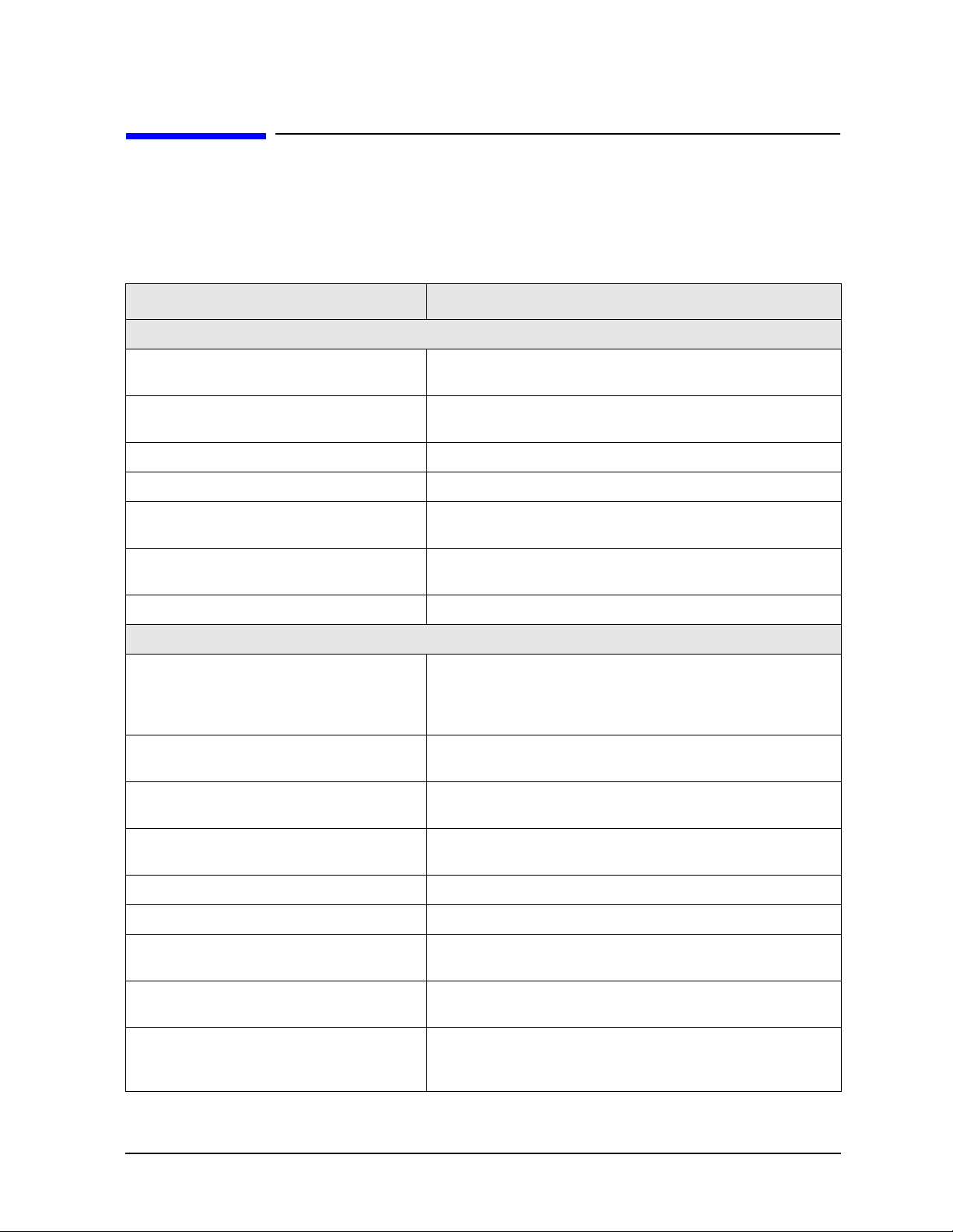
complete. The following table lists the items shipped with the analyzer.
Item Description
Accessories
Adapter, Type-N (m) to BNC (f) Two ad apters are shipped with Option 1DN.
Adapter, Type-N (m) to SMA (f) Shipped only with Option 1DN f or Ag ilent E7402A, E7403A,
E7404A, and E7405A. Not shipped with Option BAB.
Adapter, APC 3.5 (f) to APC 3.5 (f) Shipped only with Option BAB.
Adapter, BNC (f) to SMA (m) Shipped only with Option BAB.
Cable, BNC (m) to BNC (m), 203 mm Shipped only with Agilent E7402A, E7403A, E7404A, and
E7405A.
Cable, SMA (m) to Type-N (m), 220 mm Shipped only with Option 1DN for Agilent E7402A, E7403A,
E7404A, and E7405A.
Power Cable (S ee Table 1-3. on page 12 ) Connection for power source.
Standard Documentation Set
Getting Started Guide Covers unpacking and setting up the ana l y z er, analyzer
features, and how to make a basic measurement. Includes
information on options and accessories , and what to do if you
have a problem.
User’s Guide Describes analyzer features in detail, including front-panel
key descriptions.
Programmer’s Guide Describes basic spectrum analy zer programming
information, and SCPI command descriptions.
Spectrum Analyzer Measuremen t G uide Provides details on how to m easure various signals, and how
to use catalogs and files.
EMC Measurement Guide Provides details on how to make EMC measurements.
Specifications Guide Documents specifications, safety, and regulatory information.
Instru me n t Me ssag e s a nd Fu nc ti o na l Tests Include s i n stru me n t me ssages (and sugge s ti o ns for
troubleshooting them), and manual functional tests.
Programming Conversion Guide Describes SCPI programming command compatibility for
8590, ESA series analyzers.
Documentation CD-ROM Includes the documents in the standard set (listed above).
You can view and print the information as needed. See the
CD-ROM jacket for installation inf ormation.
Chapter 1 7
Page 8

Installation and Setup
Initi a l Ins pe c tion
Item Description
NOTE If you purchased one or more optional measurement personalities, the related guides for the
options you ordered are included.
Service documentation is not included in the standard documentation set. See “Options” on
page 67 for information on ordering.
If There Is a Problem
If the shipping ma terials are damaged or the contents of the container are incomplete:
• Contact the nearest Agilent Technol ogies office to arrange for r epair or replacement
(Table 6-2. on page 81). You will not need to wait for a claim settlement.
• Keep the shipping materia ls for the carrier’s inspection.
• If you must return an analyzer to Agilent Technologies, use the original (or comparable)
shipping m ate ri als (see “Returning an Analyzer for Service” on page 82).
8 Chapter 1
Page 9

Installation and Setup
Power Requirements
Power Requirements
The only physical installation of your Agilent spectrum analyzer is a connection to a power
source.
Line voltage does not need to be selected.
WARNING Failure to ground t he analyzer properly c an result in p ersonal injury.
Before turning on the analyzer, you must connect its protective eart h
terminal s to the prote ctiv e condu ctor o f th e main pow er cab le. I nser t
the main power cable plug into a socket outlet that has a protective
earth c ont act only. DO NOT defeat the earth-grou nding protection by
using an extension cable, power cable, or autotransformer without a
protective ground conductor.
If you are using an autotransformer, make su re its common terminal
is connected to the protect ive earth contact of the power source
outlet socket.
This is a Safety Class 1 Product (provided with a protective earthing
ground incorporated in the power cord). The mains plug shall only
be inserted in a socket outlet provided with a protective earth
contact. Any interruption of the protec tive conductor inside or
outside of the product is likely to make the product dangerous.
Intentional interruption is prohibited.
CAUTION VENTILATION REQUIREMENTS: When installing the product in a cabinet,
the convection int o and out of the pr oduct must no t be res tricted. The ambient
temperature (outside the cabinet) must be less than the maximum opera ting
temperature of the produc t by 4°C for every 100 watts dissipated in the
cabinet. If t he tota l p ower dissipated in the cabinet is greater than 800 watts,
then forced convection m ust be used.
This analyzer has autoranging line voltage input. Be sure the supply voltage
is within the specified range.
NOTE For more information reg arding analyzer specifications, see the
Specific ations guide.
Chapter 1 9
Page 10
Installation and Setup
Power Requirements
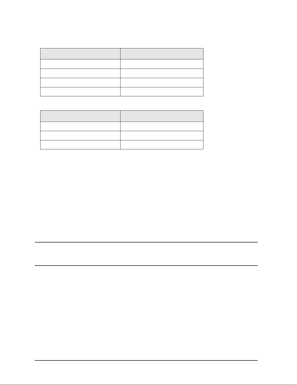
Table 1-1. AC Power Re quirements
Description Specifications
Voltage 90 to 132 Vrms (47 to 440 Hz)
Voltage 195 to 250 Vrms (47 to 66 Hz)
Power Consumption, On < 300 W
Power Consumption, Standby < 5 W
Table 1-2. DC Power Requirements
Description Specifications
Voltage 12 to 20 Vdc
Power Consumption < 200 W
Power Consumption, Standby < 5 W
Checking the Fuse
Where IEC regulations apply, use a 5 by 20 mm, r at ed F5 A, 2 5 0 V IEC approved fuse. This
fuse may be used with input line voltages of 115 V or 230 V. Its part number is 2110-0709.
Where UL/ C S A re g ul at i ons apply, use a 5 by 20 mm rated fast blo w, 5 A, 125 V UL/ C S A
approved fuse (part number 2110-0756). This fuse may only be u sed with a n input lin e
voltage of 115 V.
The line fuse is housed in a fuse holder in the upper left hand corner of the rear panel.
To remove the fuse, first di sconnect th e power co rd from the analyz er. Then i nsert the
tip of a screwdriv er into the slot at the mid dle of the fuse holder, and turn countercloc kwise
to extend the fuse holder.
WARNING For continued protection against fire hazard, replace the line fuse
only with the same type and rating. The use of ot her fuses or material
is prohibited.
10 Chapter 1
Page 11

Installation and Setup
Power Requirements
AC Power Cord
The analyzer is equipped with a three-wire power cord, in accordance with international
safety standards. This cable grounds the analyzer cabinet when connected to an
appropriate power line outlet. The cable appropriate to the original shipping location is
included with the analyzer.
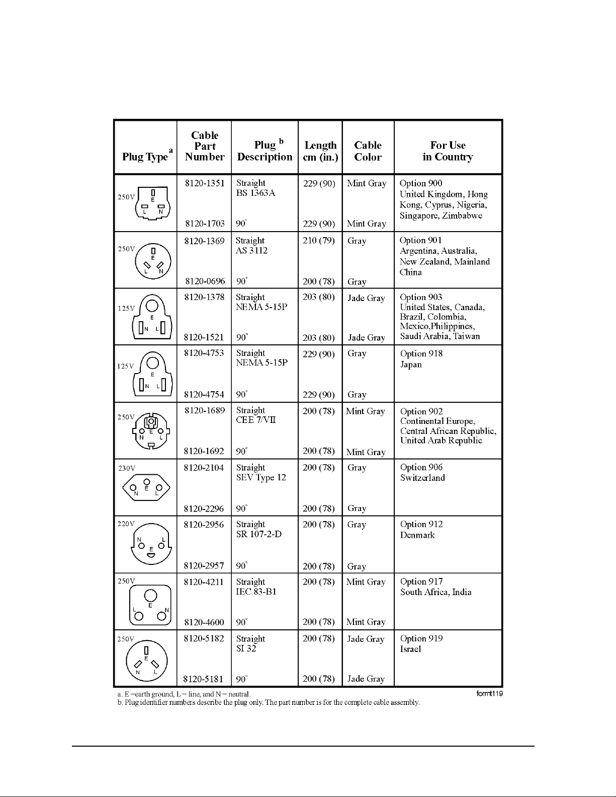
Various AC power cables are avail able that are unique to specific geographic areas. You
can order additional AC power cables for use in different areas. AC Power Cords, on
page 12 lists the available AC po wer cables, il lu st rates the plug con f i gu rations, and
identifies the geog raphic area in which each cable is a ppropriate.
NOTE The front pan e l sw itch i s a st an db y switch only; it is not a LINE sw itch
(power disconnecting device).
WARNING Install the product so that the detachable power cord is readily
identifiable and easily reached by the operator. The det a chable
power cord is the product disconnecting devic e. It disconnects the
mains circuits from the mains supply before other parts of the
product. The front panel switch is on ly a standby switch and is not a
LINE switch. Alternatively, an externally installed switch or circuit
breaker (which is readily identifiable and is easily reached by the
operator) may be used as a disconnecting device.
CAUTION Always use the three-prong AC power cord supplied with this product.
Failure to ensure adequate earth grounding by not using this cord can cause
product damage.
CAUTION This analyzer has autoranging line voltage input. Be sure the supply voltage
is within the specified range. (Refer to the specific ations guide for your
analyzer.)
Chapter 1 11
Page 12
Installation and Setup
Power Requirements
T abl e 1-3. AC Power Cords
12 Chapter 1
Page 13
Installation and Setup
Power Requirements
Batter y Information
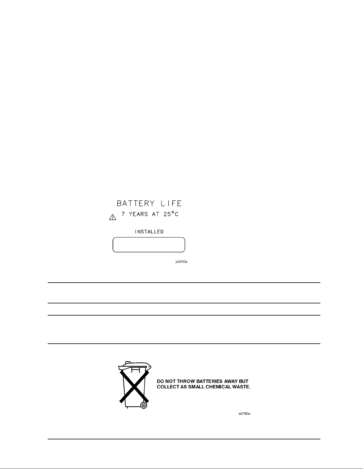
The analyzer uses a lithium bat tery to e nable the inter nal memory to reta in data. The da te
when the battery was insta lled is on a label on the rear panel of the analyzer.
See Figure 1-1.
The minimum life expectancy of the battery is 7 years at 25 °C, or 1 year at 55 °C. If you
experience problems with the battery or the recommended time period for battery
replacement has elapsed, see “Returning an Analyzer for Service” on page 82.
If you wish to replace the battery yourself, you can purchase the service documentation
that provides all necessary test and maintenance information.
You can order the service documentation for an Agilent ESA spectrum analyzer through
your Agilent Sales and Service office. The documentation is described under “Options” on
page 67.
After replacing the analyzer battery, write the date of battery replacement on the
rear-panel label.
Figure 1-1. Rear-Panel Battery Information Label
NOTE If the analyzer’s clock does not work, the problem is the ba ttery. See
“Returning an Analyzer for Ser vice” on page 82.
WARNING Danger of explosion if battery is incorrectly replaced. Replace only
with the same or equivalent type recomm ended. Discard used
batteries according to the manufacturer’s instructions.
Chapter 1 13
Page 14

Installation and Setup
T urning on the Analyzer for the Fir st Ti me
Turning on the Analyzer for the First Time
❏ Plug in the po wer cord.
WARNING If this product is to be energized vi a an externa l auto trans former for
voltage reduction, make sure that its common terminal is connected to a
neutral (earthed pole) of the power supply.
CAUTION The analyzer is shipped with a a transportation disk inserted in the disk
drive to prevent da mage to the disk drive during transportation. This
transportation disk, or a blank flop py disk, sh o u ld be inse rte d in t h e disk
drive whenever transporting the analyzer.
NOTE Do not connect anything else to the analyzer yet.
❏ Choose a power on preference using the switch on the rear panel (refer to Rear-Panel
Features, on page 3 2, item 14). The
PWR ALWAYS ON setting turns the analyzer on
whenever external power is applied. This mode is useful if an external power switch is
used to con t ro l a rack of several in st ru ments. Neve rt h e le ss, if you set the an alyzer to
standby using the front panel
Standby key (see Rear-Panel F e atures, on pag e 32, item
23) and the external power is removed and restored withi n 20 seconds, t he analyzer will
rema in in s t andby.
PWR NORM setting assigns analyzer on/off control to the front-panel On and
The
Standby keys (see “Front-Panel Connectors and Keys” on page 24, item 23). If the
analyzer is on and the external power is removed and restored within 20 seconds, the
analyzer will turn on. On the other hand, i f the exte rnal pow er is removed a nd restor ed
after 20 seconds, the analyzer will remain in standby regardl ess of the front-panel
switch settings.
❏ Press the | (On) key to turn the analyzer on.
14 Chapter 1
Page 15

Installation and Setup
T urning on the Analyzer for the Fir st Ti me
Information Screen
An information screen appears d uring the initi alization p rocess. The i nformation sc reen
contains the analyzer product number and a URL for accessing product support
information on the World Wide Web. See “Additio n al Informati on” on page 2.
NOTE The information screen displays for approximately 10 seconds before the
initialization pr o cess is com p lete.
Record t h e firmware revisi o n an d se rial number, and keep it for refe rence. If
you should ever need to call Agilent Technologies for service or wi th any
quest io n s re garding yo u r analyzer, it will be h e lp fu l to have thi s informat io n
readily available. You can also obtain the firmwa re revision and se rial
number by pressing System, More, Show System.
❏ Allow the analyzer to warm-up for 5 minutes before making a calibrated measurement.
To meet its specifications , the analyzer must meet operating temperature conditions.
If the ana ly z e r is an Agilent Technologi e s E 7402A, E7403A, E7404A , or E 7405A,
connect a BNC cable fr om the AMPTD REF OUT to INPUT 50 Ω using an adap t e r.
After a 5 minu t e warm-up, press System, Alignments, Align Now, All.
CAUTION When operating in dc coupled mode on analyzers with Option UKB ensure
protection of the inp ut mixer by limiting the input l evel to 0 Vdc, +30 dBm.
When operating in ac coupl ed mode, ensure protection of the input mixer by
limiting the input level to 50 Vdc, +30 dBm.
NOTE It is normal to hear clicking when the Auto Alignment function is on. See
“Running Internal Alignments” on page 17 for more in fo rmation.
Chapter 1 15
Page 16

Installation and Setup
Firmware Revision
Using an External Reference
If you wish to use an external 10 MHz source as the reference frequency, connect an
external reference source to the
should be greater than –15 dB m.
NOTE It is not necessary to connect the 10 MHz REF OUT to the 10 MHz REF IN on
the rear of the a n aly ze r. Doing so results in a “Frequency Reference Error”
message.
1. To use an external frequency reference, connect it to the EXT REF IN connector on the
rear panel (see “Rear-Panel Features” on page 32).
10 MHz REF IN connector on the rear panel. The signal level
Firmware Revision
To view the firmware revision of your analyzer, press System, More, Show System. If you
call Agile nt Technologies r eg ardi ng yo ur a nal yze r, it is he lpf ul t o h ave t his r evis ion and the
analyzer serial number available.
16 Chapter 1
Page 17

Installation and Setup
Running Inte rnal Alignments
Running Intern al Al ignmen ts
Each time the analyzer is powered on, the internal alignment r outine runs automatically.
The analyzer was shipped from the factory with the Alignments mode set to
Align All.
Auto,
NOTE When the Alignment routine runs, you will hear the attenuator settings
changing, which generates noise. This is not an indication of trouble.
Manually Performing an Alignm e nt
If the analyzer is an Agilent Technologies E7402A, E7403A, E7404A, or E7405A, connect a
BNC cable from the AMPTD REF OUT to INPUT 50 Ω using an adapter. After a 5 minute
warm-up, press
System, Alignments, Align Now, All.
NOTE It is normal to hear clicking when the Auto Alignment function i s on. During
the interval between sweeps , portions of the analyzer’s circuitry are
realigned. Some of the circuitry is controlled by rela ys. It is the rapid
switching of these relays between sweeps which causes the clicking sound.
Under normal operation, these relays will last over 50 years.
To eliminate the clicking sound, turn off the automatic alignment. (See the
Alignments key description in your User’s guide.”) W ith
Auto Align turned off,
however, the Align Now All function should be performed periodically. For
more information on how often to perform Align Now All when the Auto
Alignment function is off, refer to the appropriate “Specifications and
Characteristics” chapter in your specification s guide.
If
Auto Align, Off is select ed, refer to th e Specifications guide for the condit io ns required to
maintain calibration.
Chapter 1 17
Page 18
Installation and Setup
Printer Setup and Operation
Printer Se tup a nd Oper a tio n
A printer can be connected to your analyzer if it is equipped with an external I/O interface.
Supported printers accept Hewlett-Packard Printer Control Language Level 3 (PCL3) or 5
(PCL5). Refer to the docume ntat ion or s pecif ic at ions sup pli ed wit h your pri nter, or contact
the manufacturer to identify your printer’s language.
Equipment
• IEEE 1284 compliant printer cable.
• Supported and tested printers are listed below. Note that there are many PC L3/5
printers that may work with your analyzer, however, they have not been tested.
— PCL3 printers inc lu d e most HP DeskJet printe rs.
— PCL5 printers inc lu d e most HP Las e rJet printe rs.
NOTE The following printers are not compatible with your analy zer.
• HP Deskje t 720C, 722C, 820C an d 160 0C
• Epson MX-80, FX-85, Stylus, and LQ-570
Printer Models Language Type Color Capable
HP DeskJet 310, 320, 350C, 400L PCL3 yes
HP DeskJet 500C, 550C, 600, 660C, 672C,
680C, 682C, 690C, 693C
HP DeskJet 840C, 850C, 870C, 890C, 895C PCL3 yes
HP DeskJet 935C, 970C, 990C PCL3 yes
HP DeskJet 1120C, 1150C PCL3 yes
HP Inkjet 2000C PCL 3 yes
HP LaserJet III PCL3/5 no
HP LaserJet 4P PCL3/5 no
HP Lase r Je t 5L, 5M, 5N, 5P, 5S I PCL3/5 no
HP LaserJet 6L, 6MP PCL5 no
HP LaserJet 2100 Seri es, PCL3/5 no
PCL3 yes
HP LaserJet 4050N PCL3/5 yes
HP LaserJet 5000GN PCL3/5 yes
HP Professional Series 2500CM PCL3 yes
HP Professional Series 2500CM PCL3 yes
18 Chapter 1
Page 19

Installation and Setup
Printer Setup and Operation
Interconnection and Setup
1. Turn off the printer and the analyzer.
2. Connect the printer to the analyzer parallel I/O interfa ce connector us ing an IEEE 1284
complian t parallel print e r cable.
3. If appropriate, configure your printer using configuration menus or sw itches. Refer to
your printer’s documentation for mor e specific information on config uring your printer.
4. Turn on the analyzer and printer.
5. Press
Type
None None disables the analyzer from attempting t o p r int to a printer. This is
Print Setup on the front panel and then press the Printer Type menu key. Printer
accesses the fol lowing keys:
the appropriate setting if no printer is connected to the analyzer.
Custom Custom allows you to access the Define Custom menu keys. The Define
Custom
menu keys allow you to specif y pr in ter charact e r i s t ics such as
PCL Leve l a n d printer color capab il it y.
Auto Auto enables the analyzer to automatically attempt to identify the
6. Press
connected printer when the
set to
Printer Type to access the Printer Type menu keys. Press Auto to make the analyzer
Auto.
Print key is pressed or when Printer Type is
attempt to identif y the connected printer. When you press Auto, the analyzer will
respond in one of the three following ways:
• The
Print Setup menu wi ll b e displayed with the Auto key selected and no new
message will be displayed in the display status line. This indicates that the analyzer
has successfully identified the connected pri nter and no further setup is required. As
long as
Auto remain s s e le ct e d in t he Printer Type menu, the analyzer w ill attempt to
identify the printer when the front panel Print key is pressed . Th e selected printer
will be display ed by pr e ssi ng
• The
Print Setup menu wi ll b e displayed with the Custom key selected and one of the
System, More 1 of 3 , S how System.
following dia gn ost ic me ssages will be display e d in the di splay status line:
Unknown pri nter, Define Cus tom to set up pri nter
No printer res ponse , Define Custom to set up printer
Invalid pri nte r res pon se , D efi ne Cu sto m t o s et up pr in ter
This indicates that the analyzer was unable to automatically i dentify the connected
prin t e r, and
Define Custom to select spe cific printer ch aracteristi cs su ch as the print e r language
Custom has been selected i n the Pr inter Type menu. Press Print Setup,
(PCL3 or PCL5) and color p rinting capability. Once you have set these
characteristics to match those of your connected printer, the printer setup process is
complete. As long as
Custom remains s e le ct e d in t he Printer Type menu, the analyzer
will not attempt to automatica lly identify t he connect ed printer when the fr ont panel
Print key is pressed.
Chapter 1 19
Page 20

Installation and Setup
Printer Setup and Operation
• The Print Setup menu will be displa yed with the None key selected and the following
message will appear in the display status line:
Unsuppo rted pri nter, Printer Ty pe set to None
This indicates that the analyzer has successfully identi fied the connected printer,
but the printer is not supported by the analyzer. As long as
Printer Type menu, the analyzer will respond to any pri nt c ommand by disp layi ng the
None is selected in the
message Printer Typ e i s N on e in the display status line.
7. Select the desired paper size by pressing
Print Setup, More, Page S ize, then choose the
appropriate pag e siz e fo r which your printer is co n figured. This setting w ill remain
unchanged with Preset or Power Cycle.
The factory default pag e size is
More, Restore Sys Defaults is executed.
Letter. The pa ge siz e will be res et to Letter if System ,
Te sti n g Pr i n ter Operation
When you have co mpl ete d th e an alyz er’s printer setup, press
Print Setu p, Print (Screen) and
then press Print on the front p anel. If the printer is read y and the printer setup was
successful, a printout of the analyzer display will be printed. If the printer is not ready , the
message Printer Tim eout will appea r o n t h e an alyzer display. Printer Timeou t will
remain on the display until the printer is ready or until you press
ESC to cancel the
printout request.
NOTE There may be some small discrepancies in the color mapping of the analyzer
display to your co l o r printer. Du e to differences in display and printer
technologies, the default display colors do not map exactly to the printer
colors. For example trac e 1 is yellow on yo ur analyzer disp lay while i t maps to
green on your printer.
20 Chapter 1
Page 21

Installation and Setup
Protecting Against Electrostatic Discharge
Protecting Against Electrostatic Discharge
Electrostatic discha rge (ESD) ca n damage or destroy el ectronic c omponents (t he possib ility
of unseen damage caused by ESD is present whe never components a re transpor ted, stored ,
or used).
Test Equipment and ESD
To he lp reduce ESD damage that ca n oc cu r while usin g t e st equ ipment:
• Before connecting any coaxial cable to an analyzer connector for the first time each day,
momentarily short the center and outer conductors of the cabl e together.
• Personnel should be grounded with a 1 MΩ resistor-i sola ted w ris t- strap b ef or e touching
the center pin of any connector and before removing any as sembly from the analyzer.
• Be sure that all instruments are properly earth-grounded to prevent build-up of static
charge.
WARNING Do not use these first three techniques when working o n circuitry
with a voltage potential greater than 500 volts.
• Perform work on all components or assemblies at a static-safe wor kstation.
• Keep static-generating materi als at least one meter away from a ll components.
• Store or transport components in static-shielding containers.
• Always h an dle printed circu it bo ar d asse mblies by the ed ges. Th i s re du ces t h e
possibility of ESD damage to components and prevent contamina tion of exposed
plating.
For information on ordering static -safe accessories, see “Accessories” on p age 73.
Additional Information a bout ESD
For more information about ESD and how to prevent ESD damage, contact the
Electrostatic Discharge Association (http://www.esda.org). The ESD standa rds developed
by this agency are sa nctioned by the American National Standards Institute (ANSI).
Chapter 1 21
Page 22

Installation and Setup
Legal Information
Legal Information
WARNING This is a Safety Class 1 Product (provided with a protective earthing
ground incorporated in the power cord). The mains plug shall be
inserted only in a socket outlet provided with a protective earth
contact. Any interruption of the protective conductor inside or
outside of the product is likely to make the product dangerous.
Intentional interruption is prohibited.
If this product is not used as specified, the protection provided by
the equipment could be impa ired. This product must be used in a
normal condition (in which all means for protection are intact) only.
Warranty
This Agilent Technologies i nstrument product is warr anted against defects i n material a nd
workmanship for a peri od of three years from date of shipm ent. During the warranty
period, Agilent Technologies Comp any will, at its option, ei ther repair or replace products
that prove to be defective.
For warran t y s e rvi ce o r re pair, this product mu st be re t u rn e d t o a se rvice facility
designated by Ag ile nt Technologies. Buyer sh all prepay s h ip ping charges to Agil en t
Technologies and Agilent Technologies sha ll pay shipping charges to return the product to
Buyer. However, Buyer shall pay al l sh ipping char ge s, du t ie s, an d taxes for pro du ct s
returned to Agilent Technologies from another country.
Agilent Technologies warrants that its software a nd firmware des ig n at e d by Agilent
Technologies for use with an instrument will execute its programming instructions when
properly installed on that instrument. Agilent Technologies does not warrant that the
operation of the instrument, or software, or firmware will be uninterrupted or error-fr ee.
LIMITATION OF WARRANTY
The foregoing warranty shall not apply to defects resulting from improper or inadequate
maintenance by Buyer, Buyer-supplied software or interfacing, unauthori zed modific ati on
or misuse, operation outside of the environmental specifications for the product, or
improper site prepa ration or maintenance.
Should Agilent have a negotiated contract with the User and should any of the contract
terms conflict with these terms, the contract terms shall control.
NO OTHER WARRANTY IS EXPRESSED OR IMPLIED. AGILENT TECHNOLOGIES
SPECIFICALLY DISCLAIMS THE IMPLIED WARRANTIES OF MERCHANTABILITY
AND FITNESS FOR A PARTICULAR PURPOSE.
EXCLUSIVE REMEDIES
THE REMEDIES PROVIDED HERIN ARE BUYER’S SOLE AND EXCLUSIVE
REMEDIES. AGILENT TECHNOLOGIES SHALL NOT BE LIABLE FOR ANY DIRECT,
INDIRECT, SPECIAL, INCIDENTAL, OR CONSEQUENT IAL DAMAGES, WHETHER
BASED ON CONTRACT, TORT, OR ANY OTHER LEGAL THEORY.
22 Chapter 1
Page 23

2 Front and Rear Panel Features
This chapter gives you an overview of the front and rear panels of your analyzer. For
details on analyzer keys and remote progra m ming, refer to the User’s and Programmer’s
guides. For connector specifications (including input/output levels), see the Specifications
guide.
23
Page 24
Front and Rear Panel Feat ures
Front Panel Overview
Front Panel Overview
This section provides information on the analyzer’s front panel, including:
• Front Panel Connectors and K eys, and
• Display Annotations, on page 27
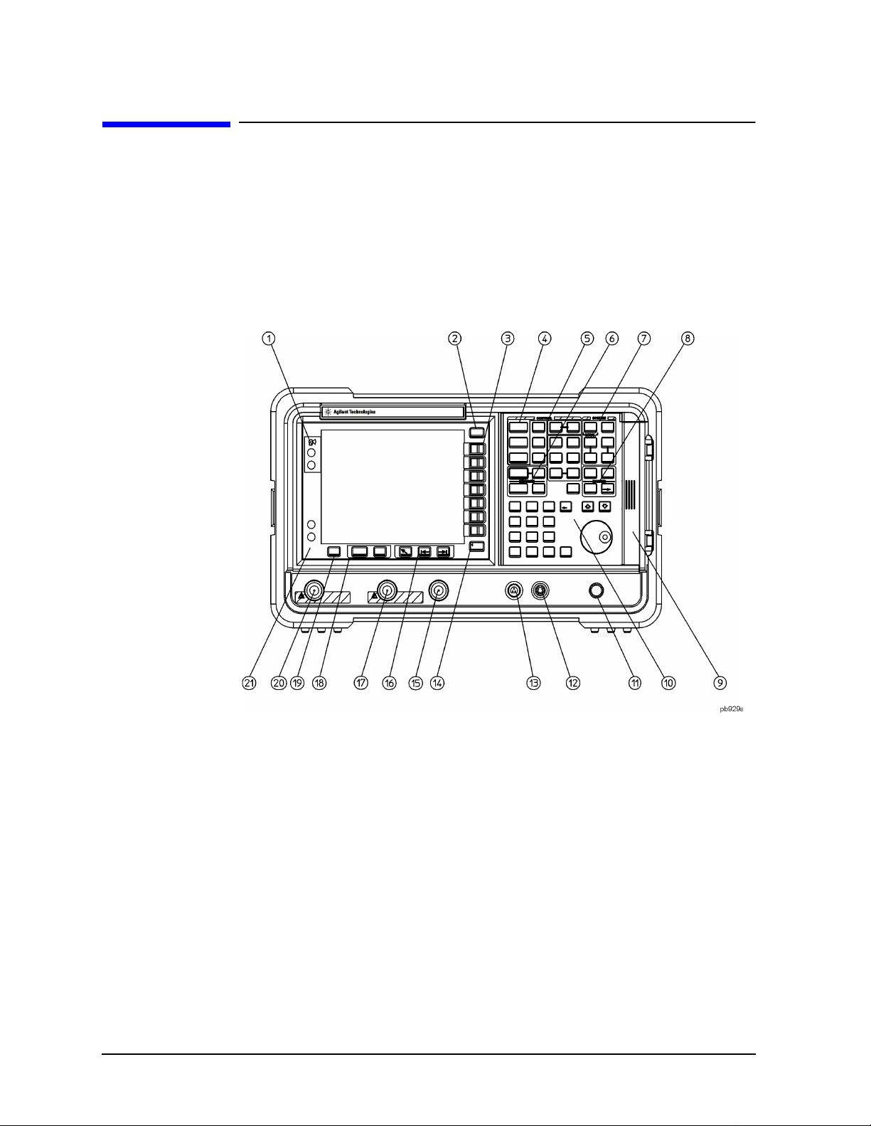
Front-Panel Connectors and Keys
1 Viewing Angle keys allow you to adjust the display so that it can be
optimally viewed from different angles.
2 Esc. The Esc (escape) key cancels any entry in progress. Esc will abort a
print (if one is in progres s) and clea r error messages from the stat us line at
the bottom of the di splay. It also clears input and tracking generator
overload conditions.
3 Menu keys are the unlabeled keys next to the scr een. The menu key
labels are the annotation on the screen next to the unlabeled keys. Most of
the labeled keys on the ana lyzer front panel (also called front-panel keys)
access menus of keys having related functions.
4 FREQUENCY Channel, SPAN X Scale, and AMPLITUDE Y Scale are the three
large keys that activate the primary analyzer functions and acces s menus
of related functions. The secondary labels on these keys (Channel, X Scale,
and Y Scale) are used in some measurements.
24 Chapter 2
Page 25

Front and R ear Panel Features
Front Panel Overview
5 CONTROL functions access menus that allow you to adjust the resolution
bandwidth, adjust the sweep time, and control the analyzer display. They
also set other analy zer parameters needed for making measurements.
6 MEASURE accesse s a menu of keys th at au t o mate some commo n an alyzer
measurements. Once a measurem ent is running,
additional menu keys for defining your measurement.
Restart access additional measur ement control functions.
7 SYSTEM functions affect the state of the entire analyzer.
Meas Setup accesse s
Meas Control and
Various setup and alignment routines are acce ssed with the
The green
File key menu allows you to save and load setups, traces, states,
The
Preset key resets the analyzer to a known state.
System key.
limit-line tables, screens, signal lists, reports, and amplitude correction
factors to or from analyzer memory or the floppy disk drive. The Save
key immediately executes the
Save Now function defined under File in
your User’s guide.
Print Setup menu keys allow you to c onfi gure hardcopy outputs . The
The
Print key im m ediately sends hardcopy data to the pr inter. See your
User’s guide for more detai ls.
8 MARKER functions control the markers , read out frequencies and
amplitudes along the analyzer trace, automatically locate the signals of
highest amplitude, and access functi ons like
9 The Media Door on the right side of the front p anel accesses the 3.5 inch
Marker Noise and Band Power.
disk drive and the Earpho ne connector. The earphone connector provides
a connection for a n earphone jack which bypasses the internal speaker.
10 The Data Control Keys, which include the step keys, knob, and numeric
keypad, allow you to change the numeric value of an active function such
as center frequency, start frequency, resolution bandwidth, and marker
position.
The data co n tro ls will change the active function in a manner pres cri be d
by that function. For example, you can change center freq uency in fine
steps with the knob, in discrete steps with the step keys, or to an exact (1
Hz resolution) value with the numeric keypad.
The Knob provides fine increm ental changes of functions such as
center frequency, reference level, and marker position. Clockwise
rotation of the knob increases values. The extent of alterati on is
determined by the size of the measurement range. The speed at which
the knob is turned affects the rate at which the values are changed.
Chapter 2 25
Page 26

Front and Rear Panel Feat ures
Front Panel Overview
For slow sweeps, the analyzer uses a smooth panning feature whi ch is
designed to move the trace display to the latest function value as the
knob is turned. When c enter, stop or, start frequency or reference level
is adjusted, the s ignal will shift right or left or up or down with the
rotation of the knob before a new swe ep is actually taken. An aste risk is
placed in the mess age block (the upper right-hand corner of the
analyzer display) to indicate that the data on the screen does not reflect
data at the current setting.
The Numeric Keypad allows entry of exact va lues for many of the
analyzer functions. You may include a decimal point in the number
portion. If not, the decimal point is placed at the end of the number.
Numeric entries must be terminated with a units key. When a numeric
entry is begun, the menu keys show the uni ts key labels. T he units keys
change depending on what the a ctive f unction is. For e xample, the units
keys for frequency spa n are
for reference level are
GHz, MHz, kHz, and Hz, whereas the units
+dBm, −dBm, mV, µV, and µA.
NOTE If an entry from the numeric keypad does not coincide w ith an allowed
function v alue (for exampl e , that o f a 12 MHz bandwidth), the analyzer
defaults to the nearest allowable value.
The Step K eys (⇓ ⇑) incr ease or decrease the acti ve function va lue. The
step size depends up on the current analyzer measurement. Each press
results in a single step chang e . Fo r t h ose parameters with fixed v alu e s
(resolution bandwidth), the next value in a sequence is selected each
time a step key is pressed. Step size is predict able (e.g ., 1 0% of spa n for
center frequency) a nd can be set for some functions (i.e., center
frequency). Out-of-ra nge values or out-of -sequence values will not occur
using these keys.
11 VOLUME. The VOLUME knob adjusts the volume of the internal spea ker.
The speaker is turned on a nd off with the
Det/Demod menu.
12 E XT KEYBOARD. The EXT KEYBOARD connector is a 6-pin mini-DIN
Speaker On Off key in the
connector. The keyboard can be used to enter screen titles and filenames.
NOTE To avoid damage to the analyzer, always turn of f power before plugging a
keyboard into the analyzer.
13 PRO BE POWER provides power for high-impedance ac probes or other
accesso ries. (+ 15 V, −12.6 V, 150 mA maximum)
14 Return. The Return key access es the previously selected menu. Conti nuing
to press Return accesses earlier menus . Re t u rn al so terminates entry of
alpha numeric functions (e.g., Title).
15 AM P TD REF OUT provides an amplitude reference signal of 50 MHz at –20
dBm. Agilent EMC mo d els E7402A, E7403A, E740 4A, and E7405 A o n ly.
26 Chapter 2
Page 27

Front and R ear Panel Features
Front Panel Overview
16 Tab Keys are used to move around in the Limit editor, the Correction
editor.
17 INPUT 50Ω (INPUT 75Ω for Option 1DP) is the signal input f or the ana lyzer.
CAUTION When operating in dc coupled mode on analyzers with Option UKB, ensure
protection of the inp ut mixer by limiting the input l evel to 0 Vdc, +30 dBm.
When operating in ac coupl ed mode, ensure protection of the input mixer by
limiting the input level to 50 Vdc, +30 dBm.
18 The Next Window key can be used to select the active window in functions
which support split-screen display modes, such as Zone markers. (Refer to
“Zone” in the User’s guide for more in formation.) In such m o de s, pre ssi n g
Zoom allows you to switch between the split-screen and full-sized display
of the active w indow.
19 Help. Press the Help key and then any front panel or menu key to get a
short description of the key function and the associa ted SCPI command.
The next key you press w ill remove the help window from the display.
20 RF OUT 50Ω for Option 1DN or RF OUT 75Ω (for Option 1DQ) is the source
output for the built-in tracking generator. Option 1DN or 1DQ only.
CAUTION If the tracking generator output power is too high, it may damage the device
under test. Do not exceed the maximum power that the device under test can
tolerate.
21 The | (On) key turns the analyzer on, w hile the Standby key turns most of
the analyzer off. An analyzer alignment is performed (if Auto Align is on)
every time the analyzer is turned on. After turning on the analyzer, allo w 5
minutes of warm-up time to ensure the analyzer will meet all
specifications.
NOTE The analyzer continues to draw power even if the line power switch is in
standby. The detachabl e power cord is the a n aly z e r di sco n n e ct in g de vice. It
disconnects the mains ci rcuits from the mai ns supply b efore other parts of the
analyz e r. The front-panel switch is only a s t an dby switc h an d is not a LINE
switch (disconnec t ing device) .
Chapter 2 27
Page 28
Front and Rear Panel Feat ures
Front Panel Overview
Display Annotation
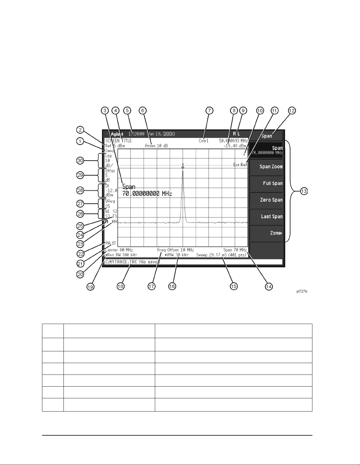
Here is an example of the annotation that may appear on an analyzer display. The display
annotation is referenced by numbers which are listed in the following table. The Function
Key column indicates which key activates the function related to the annotation. Refer to
your User’s guide for mo re in fo rmation on a specific fun ction key.
Figure 2-1. Screen Annotation
Table 2-1. Screen Annotation
Item Description Function Key
a
1
2 Reference level Ref Level
3 Ac tiv e functi on block Refer to the description of the activated funct i on .
4 Screen title
5 Time and date display Time/Date On Off
a
6
28 Chapter 2
Detector mode Detector
Change Title
RF attenuation Attenuation Auto Man
Page 29

Front and R ear Panel Features
Front Panel Overview
Table 2-1. Screen Annotation (Continued)
Item Description Function Key
7 Marker frequency Ma rker or
Marker Count On Off
8 Marker amp litu de Marker
9 GPIB annunciato rs See Table 2-2. on page 32 for more information.
b
10
11 Status Informational messages See your Instrument Messages and Functional Tests
12 Key menu title Dependen t on key se le ct io n.
13 Key menu See key label descriptions in the User’s gu ide for more
Data invalid ind ic ato r Sweep (Single) or Vi ew/Trace
manua l for more inf o rm ation.
information.
14 Fr eq ue nc y sp a n or sto p
Span or Stop Freq
frequency
a
15
16
Sweep time/Points Sweep Time Auto Man, Sweep Points
a
Video bandwidth Video BW Auto Man
17 Freq uency of f set F req Off s et
18 Display status line Displays analyzer status and error messages. Cleared
by pressing
Esc key. See your User ’s guid e for m o re
information.
a
19
20 Center frequency or start
Resolution ban d width Resolution BW Auto Man
Center Freq or Start Freq
frequency
21 Signal track Frequency, Signal Track
22 Internal preamp Am plitude, Int Preamp
c
23
24 Amplitude correction s are on
Auto align men t ro ut ine is on Auto Align
Correction On Off
(This indicates that the overall
correction state i s On. There
may be any or none of the
individual corrections On.)
25 Trigg er/Sweep Trig, Sweep See tables below for more information.
26 Trace mode
Trace
See tables below for more informati on.
Chapter 2 29
Page 30
Front and Rear Panel Feat ures
Front Panel Overview
T able 2-1. Screen Annotation (Continued)
Item Description Function Key
27 Average Average On Off
VAvg indicates video average on. PAvg indicates power
average on.
28 Dis pl ay line
Display Line On Off
29 Am plitude offset Ref Lvl Offst
30 Amp litu d e scale Scale Type Log Lin
a. A # in front of any display annotation indicates that the function is uncoupled. (Refer to your User’s guide)
b. When the (*) is displayed, it means that some or all trace data may not match the annotation due to possible changes
in analy zer settings.
c. AA indicates that auto alignment of all analyzer parameters, except the tracking generator and FM demodulation
options, will occur. AB indicates that auto alignment of all analyzer functions except the RF section (and tracking
generator and FM demodulation options) will occur. No indicator will appear if auto alignment is off.
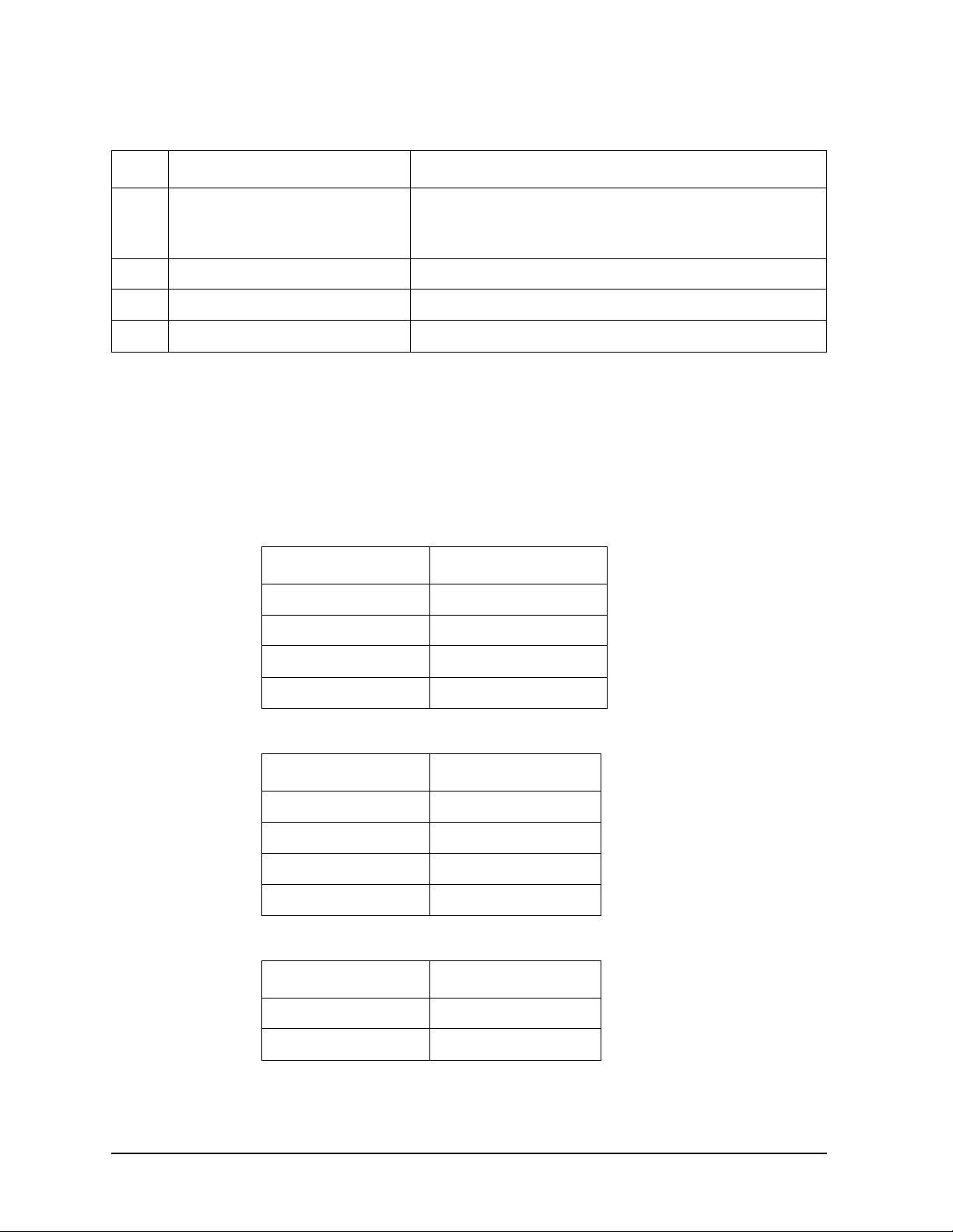
Refer to the following tables for the screen annotation codes for trace, trigger, and sweep
modes.
Table 2-2. Screen Annotation for GPIB Annunciators
Screen Annotation Description
R Remote Operation
LGPIB Listen
TGPIB Talk
SGPIB SRQ
Table 2-3. Screen Annotation for Trigger Mode
Screen Annotation Description
F Free Run
LLine
VVideo
EExternal
Table 2-4. Screen Ann otation for Sweep Mode
Screen Annotation Description
C Continuous
S Single Sweep
30 Chapter 2
Page 31

Table 2-5. Screen Annotation for Trace Mode
Screen Annotation Description
W Clear Wr ite
M Maximum Hold
VView
SStore Blank
m Minimum Hold
1 Trace 1
2 Trace 2
3 Trace 3
Front and R ear Panel Features
Front Panel Overview
Chapter 2 31
Page 32
Front and Rear Panel Feat ures
Rear-Panel Featur es
Rear-Panel Features
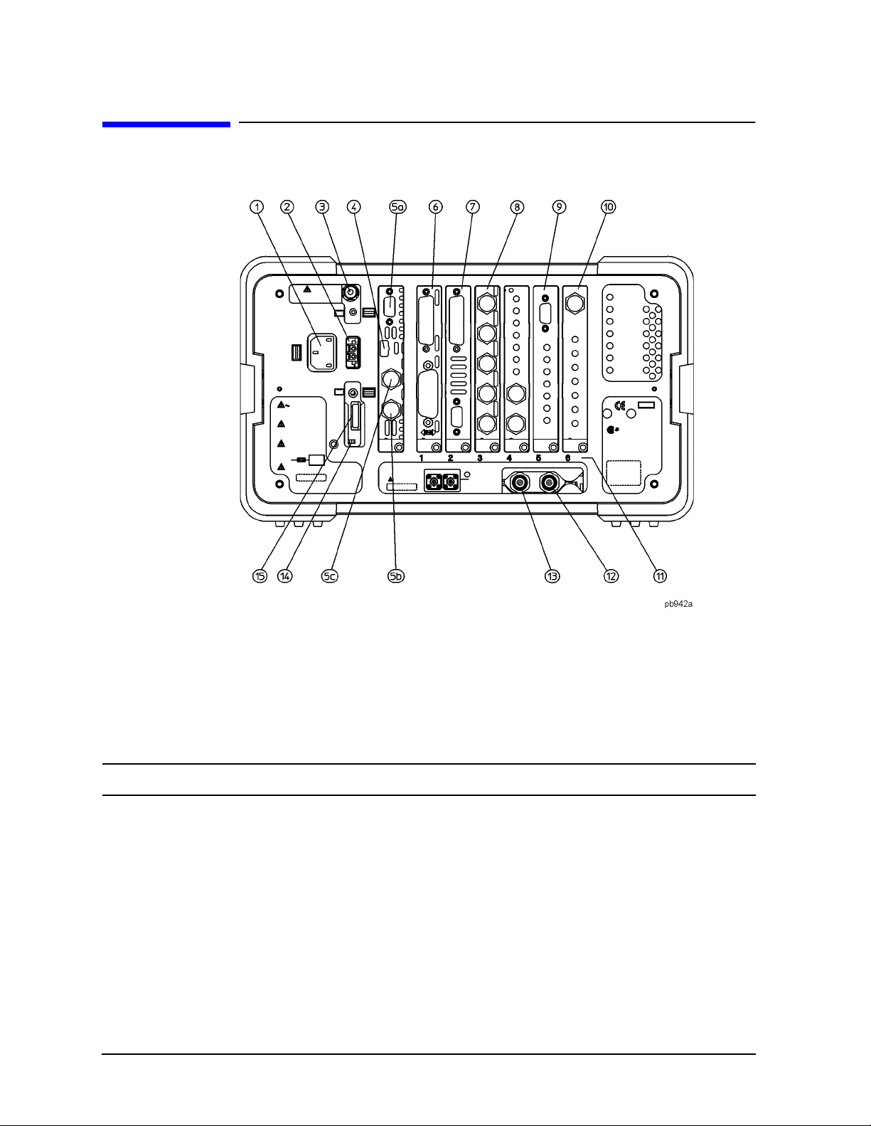
1 Power input is the input for the ac line pow er source. Make sure that the
line-power source outlet has a protective ground contact.
2 DC Power is the input f or the dc power source. Refer to the “Power
Requirements” section in t he s pecifica ti o n s gu ide for your analyzer.
CAUTION AC line po w e r an d dc power should no t be plu gg e d in simultaneously.
3 Line Fu se . The fuse is removed by twisting counterclockwise 1/4 turn.
Replace only with a fuse of the same rating. See the lab el on the rear
panel.
4 Service Connector. The service connector is for service use only.
5 Inputs/Outputs (Refer to the specifications guide for more information.)
5a VGA OUTPUT drives an external VG A co mpatible m o n it o r
with a sig n al th at has 31.5 kHz h o rizontal, 60 Hz vertical
synchronizing rate, non-interlaced.
32 Chapter 2
Page 33

Front and R ear Panel Features
Rear-Panel Features
5b GATE/HI SWP OU T (TTL) is high when the analyzer is
sweeping or when
Gate (Option 1D6) is active.
5c GA TE TRIG/E XT TRIG IN (TTL) accepts the positive edge of an
external voltage input that triggers the analyzer internal
sweep source or the gate function (Time Gate, Option
1D6).
Tab le 2-8. show the appropriate rear panel slots to be used for the optional cards available
with the Agilent EMC Analyzers. Refer to Table 2-7. if you have an Agilent EMC Analyzer.
(P) = Preferred Card Slot
(A) = Acceptable Card Slot
(–) = Unaccept able Card Slot
Table 2-6. Agilent EMC A nalyzer (E7401A, E7402A, E7403A, E7404A, E7405A)
Slot #
GPIB and Parallel Inte r face (Op tion A 4H )
b,c
RS-232 and Parallel Interface (Option 1AX)
FADC (Option AYX)
IF, Video, and Sweep Ports (Option A4J )
Frequency Extension
Quasi-Peak Dete c tio n (Op tio n AYQ)
a. Some cards may not be inst alled due to mechanical interference.
b. Only one optional remote interface (Option A4H or Option 1AX) can be installed at a time.
c. Standard with Ag ilent EMC E7401A, E7402A, E7403A, E7404A, and E 7405A.
d. Only one IF and Sweep Port option (Option A4J or Option AYX) can be installed at a time.
e. The Frequency Extension Assembly comes standard with the Agilent E7403A, E7404A and
E7405A.
d
c
e
c
a
1
23456
PAAA––
b
PAAA––
– APA––
AAAAPA
– AAAAP
––––P –
6 GPIB and parallel interfac e supports remote analyzer operation. A
parallel port is included fo r printing only.
7 RS-232 and parallel interfa ce (Option 1AX) is an option al interface .
RS-232 supports remote analyzer operation. A parallel port is included for
printi n g on ly.
NOTE Printing is only supp orted from the parallel port.
Chapter 2 33
Page 34

Front and Rear Panel Feat ures
Rear-Panel Featur es
8 IF, Video, and Sweep Ports (Option A4J or Option AYX): (Refer to the
specif ications guide for more in fo rmation.)
SWP OUT provides a vol tage ramp corresponding to the sweep of the
analyzer (0 V to 10 V).
HI SWP IN (TTL) can be grounded to stop a nd reset the sweep. Once the
sweep has been stopped, removing the gro und will tr i gge r the start of a
new sweep.
HI SWP OUT (TTL) is high when the analyzer is sweeping.
AUX VIDEO OUT provides detected video output (bef ore the
analog-to-digital conversion) proportional to vertic al deflection of the
trace. Output is from 0 V to 1 V. Amplitude-correction factors are not
applied to this si gna l.
AUX IF OUT is a 50 Ω, 21.4 MHz IF output that is the down-converted
signal of the RF input of the analyzer. Amplitude-correction factors are
not applied to thi s signal. This output is taken after the resolution
bandwidth fil te rs an d st e p g ains and before the log amplifier.
NOTE Only one IF and Sweep Port option (Option A4J or Option AYX) can be
installed at a time.
9 Quasi Peak Detector a llo ws quasi-pe ak and average me asurements, as
well as dem od u la ti n g si gnals of interest. The 9-pin serial port is rese rved
for future use.
10 Frequency Extension Assembly controls the microwave front-end
compon e n t s in t h e Ag ilent E740 3A , E7404A, and E7405A.
11 Card Slot Identification Numbers. Refer to Table 2-8. for card slot
versus o p t ion card com p atibilit y in formation.
12 10 MHz REF IN accepts an external frequency source to provide the 10 MHz,
−15 to +1 0 dB m as a timebase.
NOTE It is not necessary to connect the 10 MHz REF OUT to the 10 MHz REF IN on
the rear panel of the analyzer. D oing so will result in a Frequenc y Reference
Error message.
13 10 MHz REF OUT provides a 10 MHz, 0 dBm minimum, timebase reference
signal.
34 Chapter 2
Page 35
Front and R ear Panel Features
Rear-Panel Features
14 Power On Selection selects an analyzer power preference.
PWR ALWAYS ON setting turns the analyzer on whenever external
The
power is applied. This mode is useful if an external power switch is used
to contro l a rack of several in st ru ments. Nevert h e le ss, if you set the
analyz e r t o s t an d by using t h e fr o n t p anel Standby key (s e e Figure 2-2.
on page 22, item 21) and the external power is removed and restored
within 20 seconds, the analyzer will remain in standby.
Power Always On
Analyzer state before remov ing
power
On On On
Standby Standby On
The
PWR NORM setting assigns analyzer on/off control to the
front-panel
On and Standby keys (see Figure 2-2. on page 22, item 21).
A lapse in power
< 20 sec.
A lapse in power
> 20 sec.
If the analyzer is on and the external power is removed a nd restored
within 20 seconds, the analyzer will turn on. On the other ha nd, if the
external power is remo v e d an d re stored after 20 seconds, the a n aly z e r
will remain in sta n db y re g ardless of the front panel sw itch settings.
Power Norm
Analyzer state before remov ing
power
On On Standby
Standby Standby Standby
A lapse in power
< 20 sec.
A lapse in power
> 20 sec.
15 DC Fuse protects the analyzer from drawing too much dc power. Replace
only with a fuse of the same rating. See the label on the rear panel.
Chapter 2 35
Page 36

Front and Rear Panel Feat ures
Key Overview
Key Overview
The keys lab e le d FREQ UEN CY Channel, System, and Marker are all examples of front-panel
keys. The front-panel k eys are dark gray, light gray, green, or white in color. Front-panel
keys that are white perform an immediate action rather than bri nging up a menu. The
only green key is the
panel keys and their related menu keys can be found in user’s guide f o r yo u r anal yz e r).
Pressing most of the dark or light gray front-panel keys a ccesses menus of functions that
are displayed along the right side of the display. These are called menu keys.
Menu keys list functions other than those accessed directly b y the front panel keys. To
activate a menu key func tion, press the key immediately to the right of the annotation on
the screen. The menu keys that are displayed depend on which front-panel key is pressed
and which menu level is enabled.
If a menu key functi on’s value can be changed, it is called an active function. The function
label of the a ctive function is highlighted after that key has been selected. For exa mple,
press
AMPLITUDE Y Scale. This calls up the menu of related amplitude functions. Note the
function labeled
Ref Level also appears in the active function block, indicating that it is the active amplitude
function and can now b e changed using any of the data entry controls.
Preset key, which performs an a n alyzer reset ( A summary of all fro n t
Ref Level (the default selected key in the Amplitude menu) is highlighted.
A menu key with On and Off in its label can be used to turn the menu key’s function on or
off. To turn the function on, press the menu key so that On is under lined. To turn the
function off, press the menu key so that Off is underlined. In the manual, when On should
be underline d, it will be indicated as
Function (On).
A function with Auto and Man in the label can either be auto-coupled or have its value
manually changed. The va lue of the function can be changed manually using the numeric
keypad, knob, or step keys. To auto-couple a function, press the menu key s o that Auto is
underlined. In the manual, when
Function (Auto).
Auto should be u nderlined, it will be in d icated as
In some key menus, one k ey label will always be highlighted to show which key has been
selected. For ex ample, when you press
Marker, you will access a menu of keys in which
some of the keys ar e grouped together by a blue bar on the left side of the menu. The
Normal key, wh ich is the Marker menu default key, will be highlighted. When y ou press
another key within the blue bar region, such as Delta, the hi ghlight will move to that key to
show it has been s elected.
In other key menus, one key label will always be highlighted to show which key has been
selected but the menu is immediately exited when a selection is made. For example, when
you pr ess the
Orientation key (on the Print Setup menu), it will bring up its own menu of
keys. The Portrait key, which is the Orientation menu default key, will be highlighted.
When you press the Landsc ape key, the highlight will move to that key to show it has been
selected and the sc reen will return to the Print Setup menu.
36 Chapter 2
Page 37
Front and Rear Panel Symbols
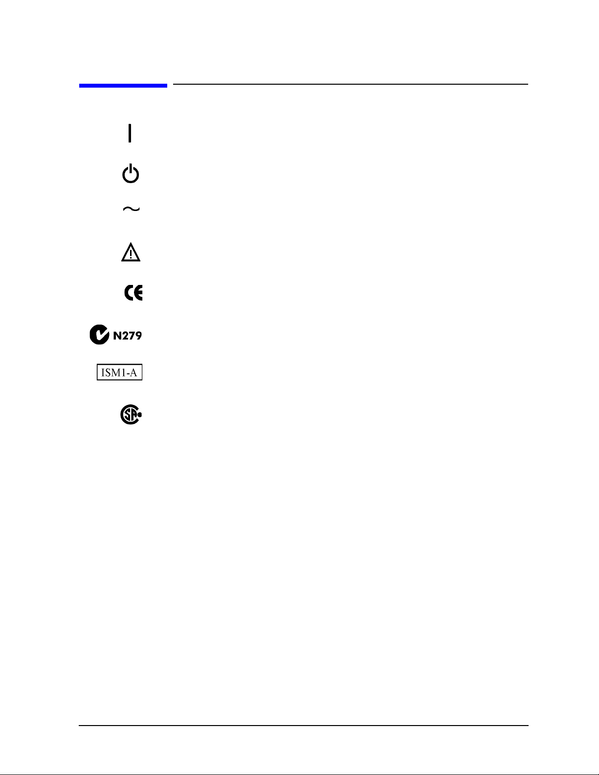
This symbol is used to indicate power ON .
This symbol is used to indicate power STAN DBY mode .
This symbol indicates the input power required is AC.
The instruction docum entation symbol. The product is marked with this
symbol wh e n it is necessary for the user to refer to in s t ru ctions in t h e
documentation.
The CE mark is a registered trademark of the European Community.
Front and R ear Panel Features
Front and Rear Panel Symbols
The C-Tick mark is a registered trademark of the Australia n Spectrum
Management Agency.
This is a sym bo l o f an Industrial Sci e n tific and Medica l Group 1 Class A
product.
The CSA mark is a regi stered trademark of the Canadian Standards
Associati on.
Chapter 2 37
Page 38

Front and Rear Panel Feat ures
Front and Rear Panel Symbols
38 Chapter 2
Page 39

3 Making a Basic Me asur em ent
This chapter provides information on basic analyzer operation. For more information on
making measurements, see the measurement guide for your analyzer.
39
Page 40

Making a Basic Measurement
This chapter is divided into the following sections:
•“Using the Front Panel” on page 41 .
•“Presetting the Spectrum Analyzer” on pag e 4 2 .
•“Viewing a Signal” on page 43.
CAUTION Ensure that the total power of all signals at the a nalyzer i np ut d oes not
exceed +30 dBm (1 watt).
Basi c As sumption
The material in this chapter is presented with the assum ption that you understand the
analyzer’s front and rear panel layout, and display annotations. If you do not, refer to
“Front an d R e ar Panel Featu res” on page 23.
40 Chapter 3
Page 41

Making a Basic Measurement
Using the Front Panel
Using the Front Panel
Entering Data
When setting measurement parameters, there are several ways to enter or modify the
value of the active function:
Knob
Arrow Keys
Numeric Keypad
Unit Softkeys
Enter Key
Increments or decrements the current value.
Increments or decrements the current value.
Enters a specific value. Then press the desire d term inator (either
a unit softkey, or the
Terminate a value that requires a unit-of-measurement.
Terminates an entry when either no unit of measure is needed, or
you want to use the default unit.
Enter hardkey).
Using Menu Keys
Menu Keys (which appear along the right side of the display) provide access to many
analyzer functions. Her e are examples of menu key types:
Toggle A llows you to activate/deactivate states.
Example: Toggles the selection (underlined choice)
Submenu Displays a new menu of softkeys.
Example: A submenu key allows you to view a new
Signal Track
On Off
Catalog
each time you press the key.
menu of softkeys related to the submen u
key category.
Choice Allows you to make a selection from a list of values.
Example: A choice key dis play s t he c urrentl y sele cte d
Adjust Highlights the softkey and sets the active function.
Examples: Pres s th i s type of key an d en ter a valu e.
Y Axis Units
dBm
CF Step
13.2550000 GHz
Attenuation
10.00 dB
Auto Man
submenu choice, in this example, dBm.
When the choice is made, the submenu
automatic a ll y returns.
The de fa u l t for softke y s w i th an automatic
(
Auto) or manual (Man) choi ce is automatic.
After you enter a value, the selectio n
changes to manual. You can also press the
softkey twice to change to manual.
Chapter 3 41
Page 42

Making a Basic Measurement
Presetting the Spectrum Anal yzer
Presetting the Spectr um Analyzer
Preset provides a known starting point for making measurements. The analy zer has
three types of preset:
Factory Preset Restores the analyzer to its factory-defined state.
User Preset Restores the analyzer to a user-defined state.
Mode Preset This type of preset r estores the currently selected mode to a known
state.
For details, see the User’s guide.
When
preset. When
Preset
Preset Typ e is set to Factory, pressing the green Preset key triggers a factory
Preset Typ e is s e t to User, pressing Preset displays th e s o ft k eys Factory
, User Preset, and Mode Preset (i f applicable); yo u t h e n s ele ct the preset you wan t .
If Preset Type is set to Mode, but a pe rs o n ality is no t in s t alled, pressing Preset triggers a
factory preset.
Creating a User Preset
If you constantly use settings which are not the factory defaults, use the following steps
to create a user-defined preset:
1. Set analyzer parameters as desired.
2. Press
user preset state.
3. Press
option.
Disa b l i n g U se r Preset
Go to the Power On/Preset menu (press
of Factory or Mode.
System, Power On/Preset, Save User Preset to set the current parameters as the
Preset to select User in the s ame softkey menu to enable user preset as an
System, Power On/Preset) and select a Preset Type
42 Chapter 3
Page 43
Making a Basic Measurement
Viewing a Signal
V i e w i ng a Signal
1. Press Preset. If the softkeys Factory Preset and User Preset appear, select
Factory Preset.
2. Connect the analyzer’s rear panel 10 MHz REF OUT to the front-panel input.
Setting Reference Level and Center Frequency
NOTE The display examples in this section are made using various a nalyzer
models, you may see some va riations depending upon your analyzer.
3. Set the amplitude units to dBm; P ress
AMPLITUDE, More, Y-Axis Units, dBm
4. Set the reference level to 1 0 dBm: Press AMPLITUDE, 10, dBm.
5. Set the center frequency to 30 MHz: Press
FREQUENCY, Center Freq, 30, MHz.
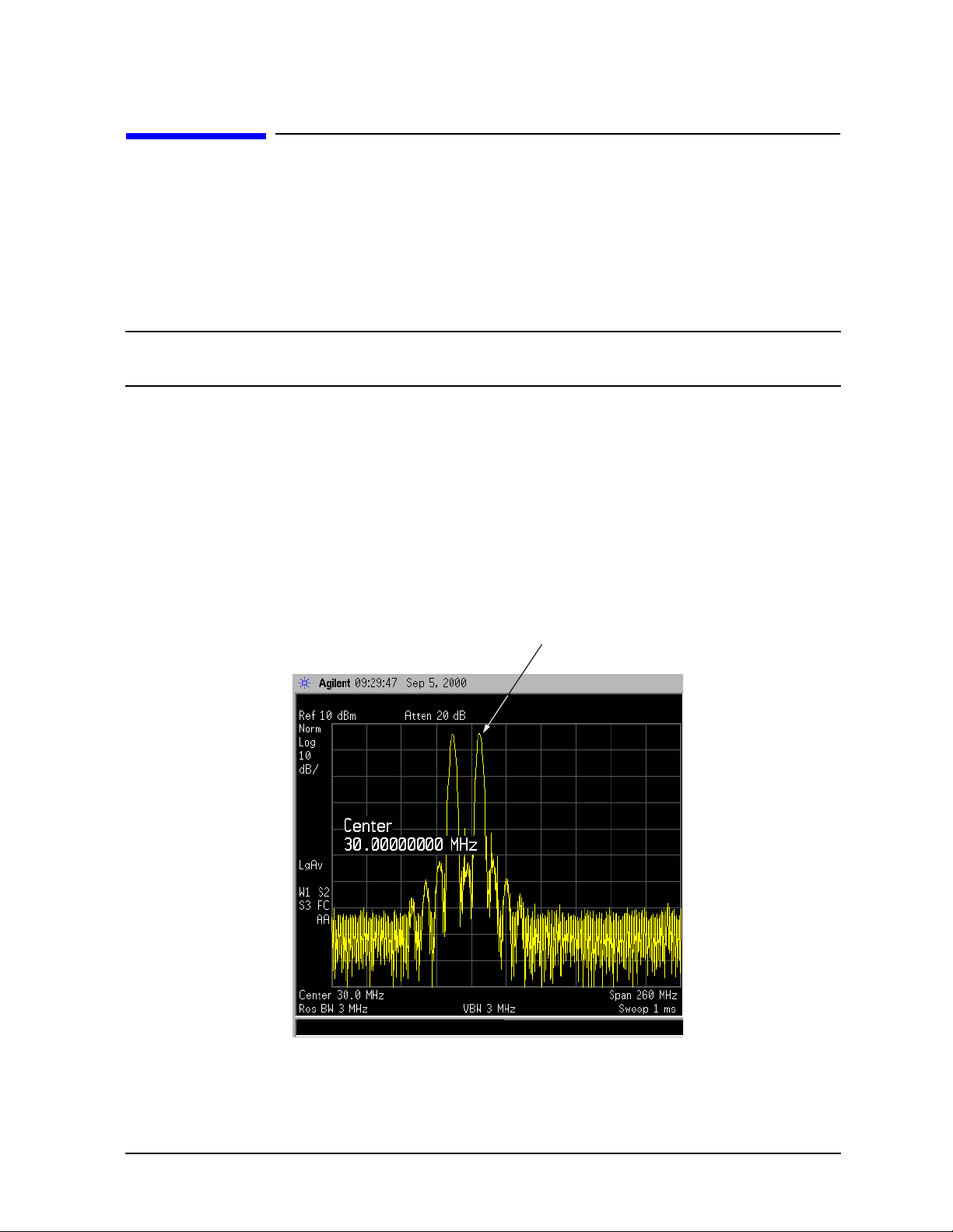
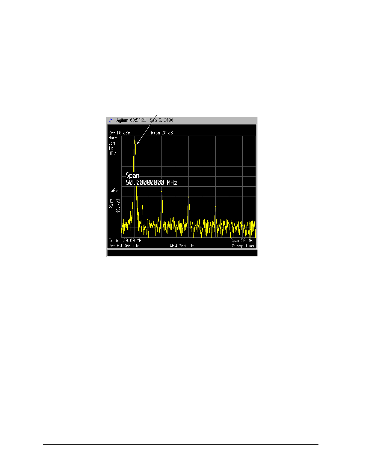
The 10 MHz reference signa l spectrum appears on the display, as shown in
Figure 3-1.
Figure 3-1 10 MHz Internal Reference Signal and Associated Spectrum
10 MHz Peak
Chapter 3 43
Page 44
Making a Basic Measurement
Viewing a Signal
Setting Frequency Span
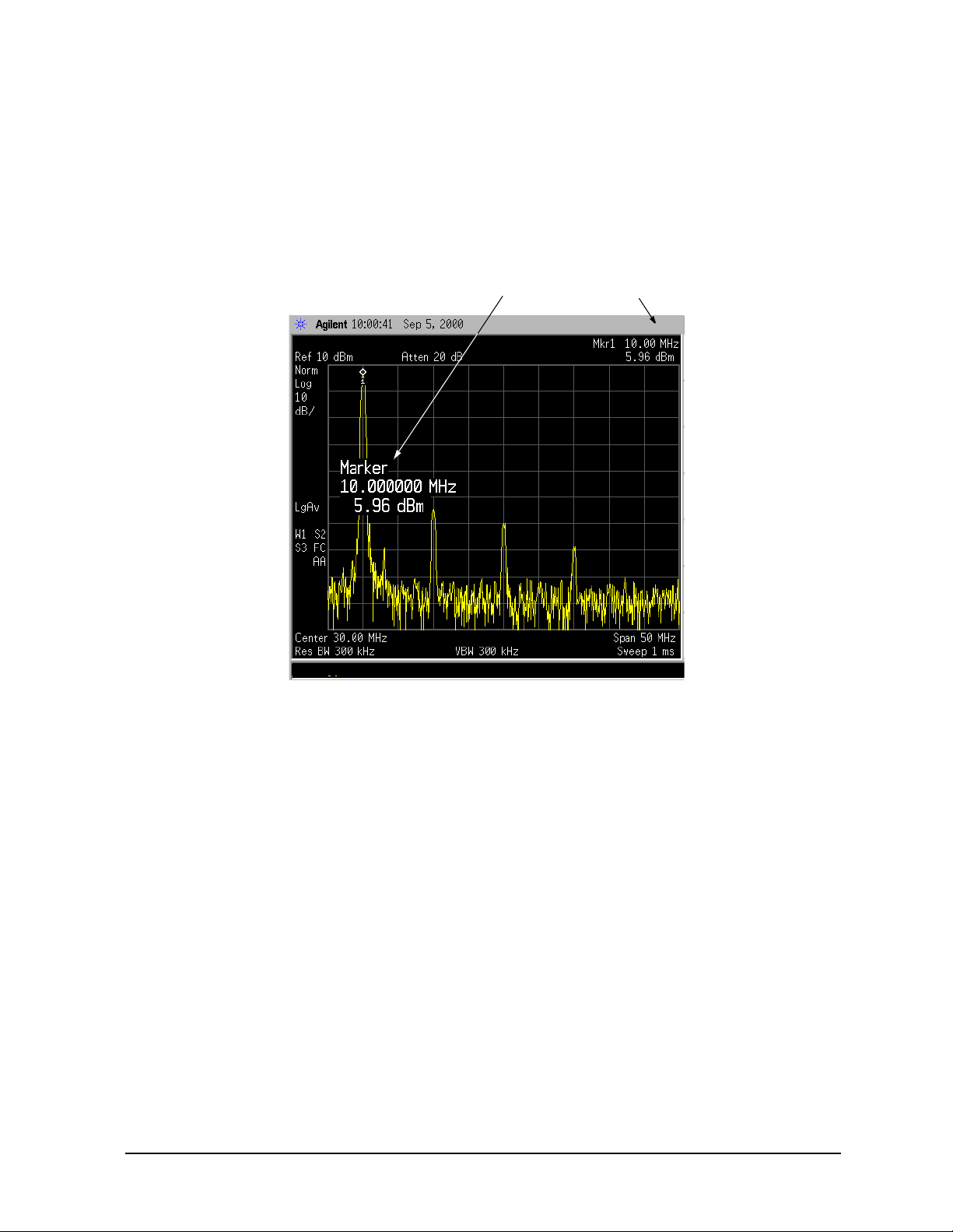
6. Set the frequency span to 5 0 MHz: Press
This displays the si gnal as shown in Figure 3-2.
Figure 3-2 Span Changed to 50 MHz
10 MHz Peak
SPAN, 5, 0, MHz.
Reading Frequency & Amplitude
7. Place a marker (labeled 1) on the 10 MHz peak, as shown in Figure 3-3.
Press
Peak Search.
Note that the frequency a nd amplitude of the marker appear both in the active
function block, and in the upper-right corner of the scr een. You can use the knob, the
arrow keys, or the softkeys in the Peak Search menu to move the m a rker. Pressing
Esc removes the value from the display.
8. If you have moved the marker, return it to the peak of the 10 MHz signal.
Changing Reference Level
9. Press
AMPLITUDE, and note that ref erence level (Ref Level) is now the active function.
Press Marker ➞, Mkr ➞ Ref Lvl.
Note that changing the reference level changes the amplitude value of the top
graticule line.
44 Chapter 3
Page 45
Making a Basic Measurement
Viewing a Signal
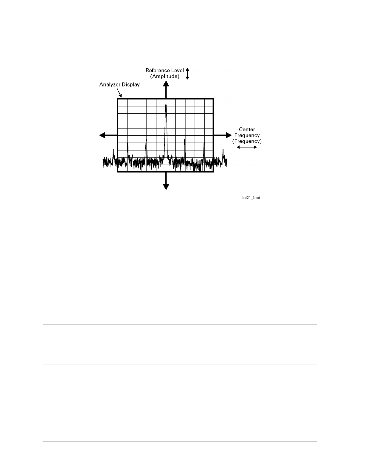
Figure 3-4 shows the relationship between center frequency and reference level. The
box represents the analyzer display. Changing the center fr equency changes the
horizontal placement of the signal on the display. Changing the reference level
changes the vertical placement of the signal on the disp lay. Increasing the span
increases the fre que n cy range that appears ho ri zo n tall y ac ro ss t he display.
Figure 3-3 A Marker on the 10 MHz Peak
Marker AnnotationActive function block
Chapter 3 45
Page 46
Making a Basic Measurement
Viewing a Signal
Figure 3-4 Relationship Between Frequency and Amplitude
Improving Frequency Accuracy
10.While not all of the zeros following the decimal in the active function block are
significant, the numb ers after the decimal in the marker a nnotation (upper-right
cor ner of screen) are significant. To improve the ac curacy of the frequency reading in
the marker annotation, turn on the frequency count function by pressing
11.Note softkey
Marker Co unt On Off. If Off is underlined, press the softkey to toggle
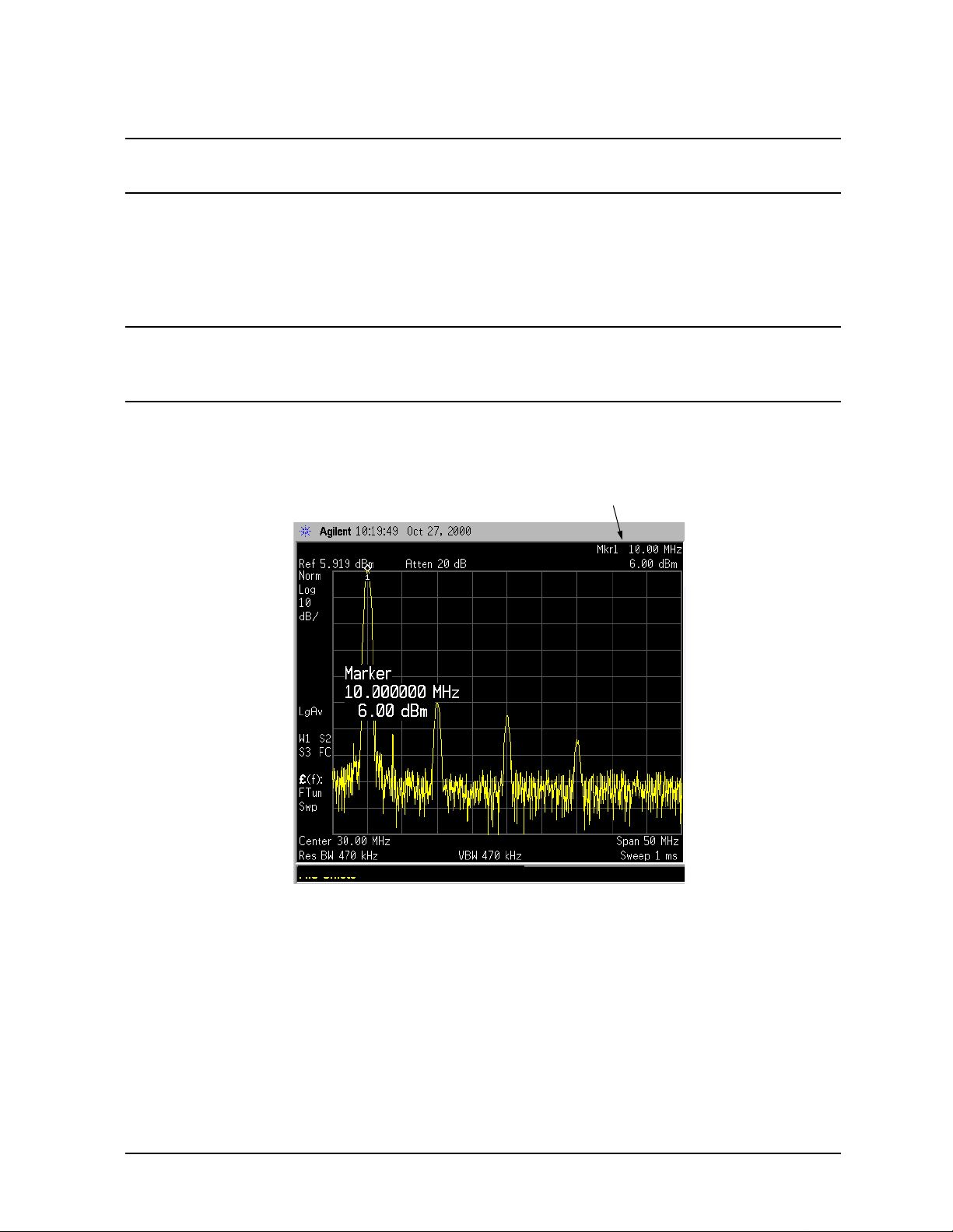
Freq Count.
marker count on.
As shown in Figure 3-5:
• The marker annotation changes from Mkr1 to Cntr1.
• The displayed resolution in the marker annotation improves.
NOTE When you use the frequenc y count functio n, if t he ratio of the r esolutio n
bandwidt h t o th e span i s le ss t h an 0. 002, the following message
appears on the display: Marker Coun t: Widen Re s B W
This indicates that the resolution bandwidth is too narrow.
12.Press
Marker ➞, Mkr ➞ CF to move the 10 MHz peak to the center of the display.
Valid Marker Count Range
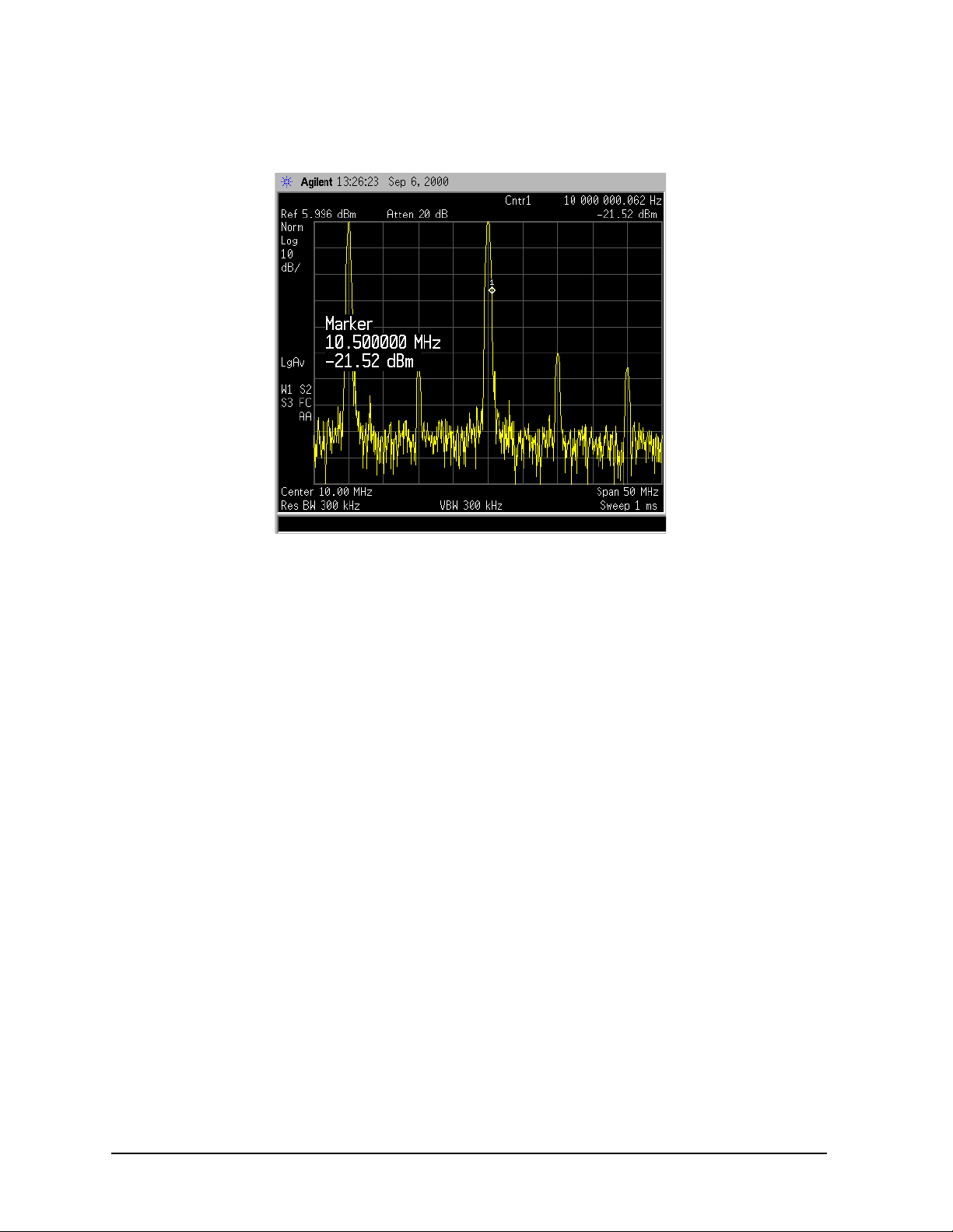
13.Move the marker down the skirt of the 10 MHz peak. Note that although the reado ut
in the active function changes, as long a s the marker is at le ast 26 dB above the noise,
the counted value (upp er-rig ht corner of displa y) does not change (see Figure 3-6). For
an accurate count, the marker does not have to be at the exact peak.
46 Chapter 3
Page 47
Making a Basic Measurement
Viewing a Signal
NOTE Marker count functions properly only on CW signals or discrete peaks.
For a vali d re ading, the marker must be ≥26 dB above the noise.
14.Press
BW/Avg, Res BW, then enter a new value. This ac tion makes the resolution
bandwidth the active functi on and all ows you to expe riment with different res olut ion
bandwidth (RBW) values.
15.Press
Marker, Off to turn the marker off.
NOTE After properly setting the analyzer to display your signa l, you can save
the settings as either a user preset (press
User Preset), or a file (see “Saving a File” on page 5 4).
System, Power On/Preset, Save
Figure 3-5 Increasing Marker Frequency Accuracy
Frequency Count
increases accuracy
Chapter 3 47
Page 48
Making a Basic Measurement
Viewing a Signal
Figure 3-6 Using Marker Counter
48 Chapter 3
Page 49

4 Viewing Catalogs and Saving Fil es
49
Page 50

Viewing Catalogs and Saving Files
File Menu Functions
File Menu Functions
This chapter descri bes how to use the functions located under the front-panel File key.
Data storage and retrieval a re handled s i mila rly to that of per s onal c omputers (PCs ). Like
PCs, these analyzers include an internal storage drive and a floppy disk drive, both of
which have directory and sub-directory capability.
NOTE The descrip tio n s in th is se ct ion assume the analyze r has firmware revi sio n
A.04.00 o r later. Th e file menu fun ct i on s in earlier firmware are diffe re nt. If
you would like to upgrade your analyzer to the latest fir m ware revision,
please visit the fol lowing web site:
http://w ww. agi le nt. com /f ind /em c
You will learn how to do all of the following:
• locate and vie w files in the catalo g
• create a di re ct o ry
• format a floppy disk
• save a file
• load a file
• rename a file
• copy a file
• delete a file
NOTE The display examples in this s ection are made usin g various analyzer models,
you may see some varia tions depending upon your analyzer.
Locating and viewing files in the catalog
Techniques for locating files and directories are consistent throughout the various file
menu functions. Although this section provides specific information about navigation in
the catalog, you may wish to refer back to this section when performing other operations of
the file menu.
Press
File, Catalog to bring up a screen dis p lay as shown in Figure 4-1.
50 Chapter 4
Page 51
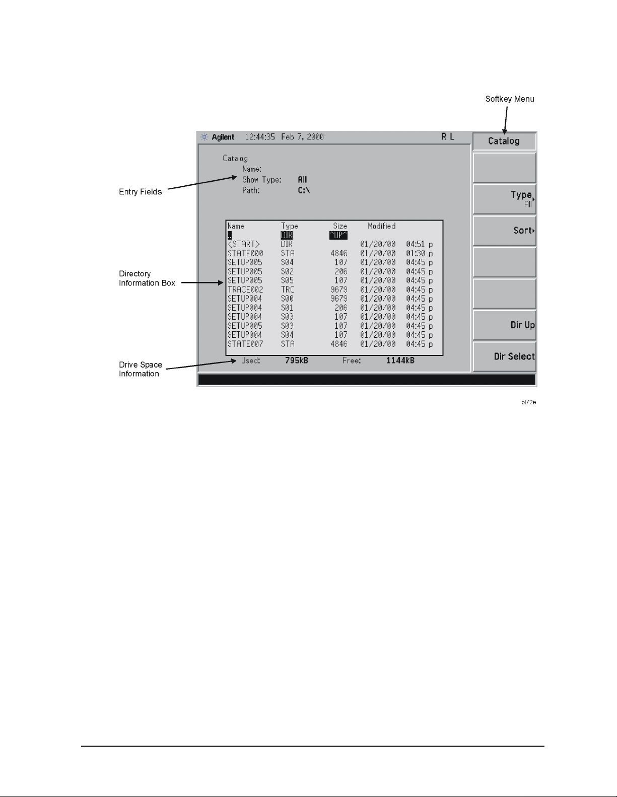
Figure 4-1. Catalog Menu
Viewing Catalogs and Saving Files
File Menu Functions
1. The entry fields show the parameters for the files viewed. Entry fi elds that are being
modified or are modifiab le a re indi cated by hig hlighting (inverse video). Each file menu
function has its own unique set of entry fields perta ining to that funct ion. Below are the
fields listed under the catalog key:
a. Name: field states the filenam e.
b. Show Type: field displays the type of files viewed.
c. Path: field displays the drive and directory location of the fil es.
2. The directory information box displays the drives, directories, and/or files currently
descri bed in th e ent ry fi elds . Hig hli ght in g a row o f in for ma tion sel ect s tha t loc a tio n and
updates the entry fields. There are four column headings i n this area of the display.
They are described as follows:
a. Name: column states the drive ([-A-] or [-C-]) if at the top level on the d rive,
directory name, or filename.
b. Type: column displays the extension of the filename, for example,
.SET, .STA, .TRC. Directories are displayed as DIR and drives have nothing listed
under Type:. T hey are only designated by the Name: column ([-A-] or [-C-]).
c. Size: column displays the size of the file in bytes.
d. Modified: column displays the date and time the last change occurred.
Chapter 4 51
Page 52

Viewing Catalogs and Saving Files
File Menu Functions
3. The softkey menu has four options:
Type: allows you to choose the type of file you wish to view. (You may view all types
a.
by using the
Sort: Under the Sort key, you can sort by any of the four columns and you can choose
b.
All key under Type.)
up (ascending) or dow n (descending).
Dir Up: moves you up one directory level. If you are alrea dy at the top level, this key
c.
moves you up to the drive level, displaying the available disk drives.
Dir Select: moves you down into the hi ghlighted directory or up into the next level
d.
(directory or dri ve) if the “. .” under the Name: column is high lighted.
NOTE Navigation keys: Use the fr ont-panel Step Keys or Knob and the Dir Up or Dir
Select keys to move around in the directory information box.
4. The drive space line shows the num ber of bytes used on the driv e and the number of
bytes still free on the drive.
Creating a directory
Directorie s an d su b-directories can be created on both the A: floppy disc and the i n ter n al
C: drive . This allow s maximum fl e xibility in or ganizing fi le s . Fo r this exam p le , we will
create a director y on the C: drive.
1. Press
the entry fields wil l be Dir Name: and Path : and the Heading will read: Directories.
2. Navigate through the file system until the Path: field displays C:\. (Use the Step Keys,
Knob, Dir Up, and/or Dir Select keys.)
3. Press
is also available for the filename.) Press
contains this directory title. (Use the
corrections.)
4. Press
appears on the screen. Then the status bar displays: Dire cto ry C: \ST ART c rea ted .
5. To make a sub-directo ry, scroll down to the START directory you just created and press
Dir Select. The Pa th : field should now read: C:\STAR T\. Re pe at Steps 3 and 4 ab ov e ,
using a new name. The status bar no w sh o u ld read: Directory C:\ START \new nam e
created.
File, More 1 of 2, Create Dir. Your screen should look similar to Figure 4-1, except
Name and enter the name, “START” using the Alpha Editor. (The numeric keypad
Enter (hardkey) when the Dir Name: field
Bk Sp hardkey on the front panel to make
Create Dir Now to execute the operation. The message: Creating D ire cto ry
52 Chapter 4
Page 53
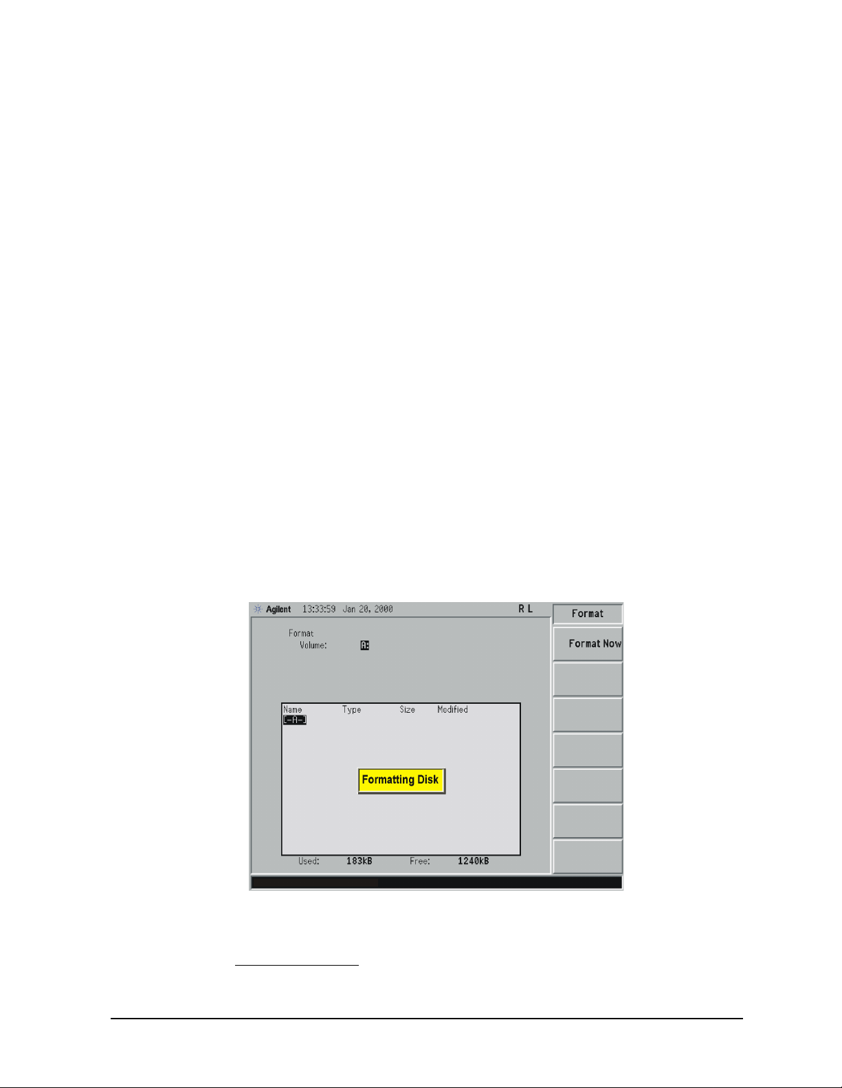
Viewing Catalogs and Saving Files
File Menu Functions
Formatting a Floppy Disk
You can format a flopp y disk in the analyzer. The format is MS-DOS1. Note that it is not
necessary to format y our floppy disk with the analyzer; preformatted disks can be used
with the analyzer.
1. Place the 1.44-MB disk you wish to format into the floppy drive (A:\) of the analyzer.
Only 1.44-MB floppy disks are supported by the analyzer. Therefore, 720-kB floppy
disks wi ll not work re liably.
2. Access the
Format key by pressing File, More, and then Format. The dire cto ry i nfo rma ti on
box is active (highlighted), however, only the floppy disk volume [ -A- ] is shown on the
display.
The directory information box displays all files present on the floppy disk inserted in
drive “A:”. If you have not inser ted a disk into drive “A:”, or the disk you are attempti ng
to format has no p re-existing formatting, the error m essage: bad, missing, or
unforma tted dis k is displayed in the status line.
3. Press
Format Now. The following message appears in the display window: WARNING: You
are abo ut to de str oy AL L d ata o n V olu me A: . P res s For mat No w aga in to
proceed or any othe r key to abo rt. To abor t disk format, press any key but
. When a di sk is formatted, all da ta o n the di sk is destroyed.
Now
4. Press
Format Now a second time to format the disk. You will see the message:
Formatt in g D isk in the display window. Pressing any other key after recei ving the
warning in step 3 on page 53, will abort the formatting process. See Figure 4-2. The
format process takes ap proximately three minutes.
Figure 4-2. Format Menu
Format
5. When form at ting is complet e , a message, Volume A: f orm att ed appears on the status
line. The disk is now ready to save files.
1. MS-DOS is a U.S. registered trademark of Microsoft Corporation.
Chapter 4 53
Page 54
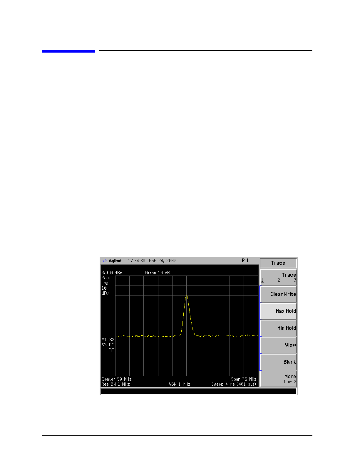
Viewing Catalogs and Saving Files
Saving a File
Saving a File
You can save fil e s (se t u ps, stat e s, tr aces, limits, correcti o n s, sign al lists, reports, or
screens) to a floppy disk (A:\), or the internal dr ive (C:\). In this example you wil l save a
trace to the inter nal C: drive.
Step 1. Set up the analyzer trace
1. Perform a factory preset by p ressing Preset, Factory Preset (if present).
2. Turn on the internal 50 MH z alignme n t si gn al of the analyzer as follo ws:
• For the Agilent E7401A, use the internal 50 MHz alignment signal of the analyzer
as the signal being measured. Press
• For all other models connect a cable between the front-panel AMPTD REF OUT to
the analyzer INPUT, then press Input/Output, Amptd Ref Out (On).
Input/Output, Amptd R ef (On).
3. Set the center frequency to 50 MHz by pressing press
4. Set the span to 75 MHz by p ressing
SPAN, Span, 75, MHz. The reference signal will
FREQUENCY, Ce nt er Fr e q, 50, MHz.
appear on the dis pla y.
5. Set the resolution bandwidth to 1 MHz by pressing
BW/Avg, Resolution BW, 1, MHz.
6. View trace 1 and put it into maximum hold by pressing
should already by underline d, but i f not, pr es s
press
Max Hold.) Your analyzer display should look s imilar to Figure 4-3.
Trace 1 2 3 unti l 1 is under li ned and then
Figure 4-3. Viewing Trace 1
View/Trace, Max Hold. (Trace 1
7. Activate trace 2 an d put it into m in i mum hold by pre ssing
Trace (2), Min Hold. Y our
analyzer display should look similar to Figure 4-4.
54 Chapter 4
Page 55
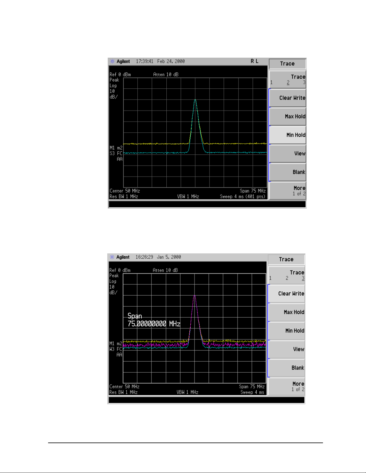
Figure 4-4. Viewing Traces 1 and 2
Viewing Catalogs and Saving Files
Saving a File
8. Activate trace 3 by pressing
Trace (3), Clear Write. Your a nalyzer display should look
simi lar to Figure 4-5 .
Figure 4-5. Viewing Traces 1, 2, and 3
Chapter 4 55
Page 56

Viewing Catalogs and Saving Files
Saving a File
Step 2. Save the file
1. To access the Save menu, press, File, Save.
2. Select the type of file you want to save. In this exampl e you are saving a trace; press
Type, Trace.
3. Se le ct the trace yo u wish t o save (1, 2, 3, or all traces). In this example you wi ll save
trace 3; press
4. Select the format you wish to use for saving the trace, either trace plus state
Trace + State) or com ma separated val u e (CSV). In this example you will save as trace
(
plus state; p ress
Source (softkey), Trace 3.
Format, Trace + State.
5. En t e r a fi le name by pressing
Name. The Alph a E ditor appears . For this example you
will name the file, “TEST1”. (The numeric keypad is also available for the filename.)
Note that the file extension is always set by the system and for this file type the
extension is TRC. You must now press the
Enter (hardkey) to get back to the Save menu.
NOTE You need to use a filename that does not already exist in the current
directory. The filena me is limited to eight character s, alpha (A-Z) or numeric
(0-9) in any com bination. The analyzer will not allow you to overwrite an
existing file. If you select a file n ame that already exis ts, the statu s bar will
displa y the message: File already ex ists . If you do not choose a filename,
the analyzer will automatically generate a name based on the type of file you
are saving (Setup: SETUP, Sta te: STATE, Trace: TRACE, Limits: LIMIT ,
Corrections: COREC, Screen: SCREN). It also generates a three digit integer
(starting at 000 and extending through 999, remembering the previously
saved valu e t h ro u gh a power cycle ) wh i c h it adds to the name, fo r e xample:
TRACE05 6. TRC. Also note that this three digit integer increments upon each
attempted save until a unique filename is created, without regard to the
success of the sav e .
6. T h e d es ti nation for th e sa ve d file is show n in t h e Path: field. In this example, you will
sel ect the path as C:\START\ . If the correct location is not listed in the Path: field,
change dire ct o ri e s as fo llows:
a. Press
Dir Up or Dir Select and use the step keys or knob, to highlight the desired
destination dir e ct o r y.
b. Press
7. Press
Dir Select and confirm your choice displayed in the Path: field.
Save Now or Save (hardkey) to save the fi le to the C:\Start\ loc ation. The
message Saving Now is displayed during this operation. For this example, the status
line displays: C:\S TAR T\T EST 1. TRC fi le sa ved.
NOTE When saving to drive (A:), never remove the floppy disk d uring the save
operation. To do so could corrup t all data on the floppy disk.
56 Chapter 4
Page 57

Viewing Catalogs and Saving Files
Loading a file
1. Reset the analyzer by pressing Preset, Factory Preset (if p resent).
Saving a File
2. To access the
Load menu, press File, Load.
3. Select the type of fil e you want to load (setup, state, trace, limits, or correct ions) . I n this
example you are loadi ng a trace file; press
Ty pe, Trace.
NOTE Not all file types can be loaded back into the analyzer. For example, Screen
files a n d C SV (comma separated value) files cannot be loaded. CSV a n d
Screen files are designed for use with a PC.
4. Select the directory where y our file is located. In this example, select the C:\S TAR T\
directory. (Use the front-panel step keys, knob,
Dir Up, and/or Dir Select keys to loca te
the directory.)
5. Select the file you want to load into the analyzer by moving the cursor with the
front-panel knob to hi ghlight the f ile name. In this ex ample the f ile is TES T1. TRC . Sel ect
the trac e in t o which you wish to load t h e fi le. In this e xample, load it into Trace 2
Destination, Trace 2).
(
6. Press
Load Now to load the specified file. Your display should look similar to Figure 4-6.
The status bar reads: C:\START\TES T1 .TR C f ile l oad ed.
Chapter 4 57
Page 58
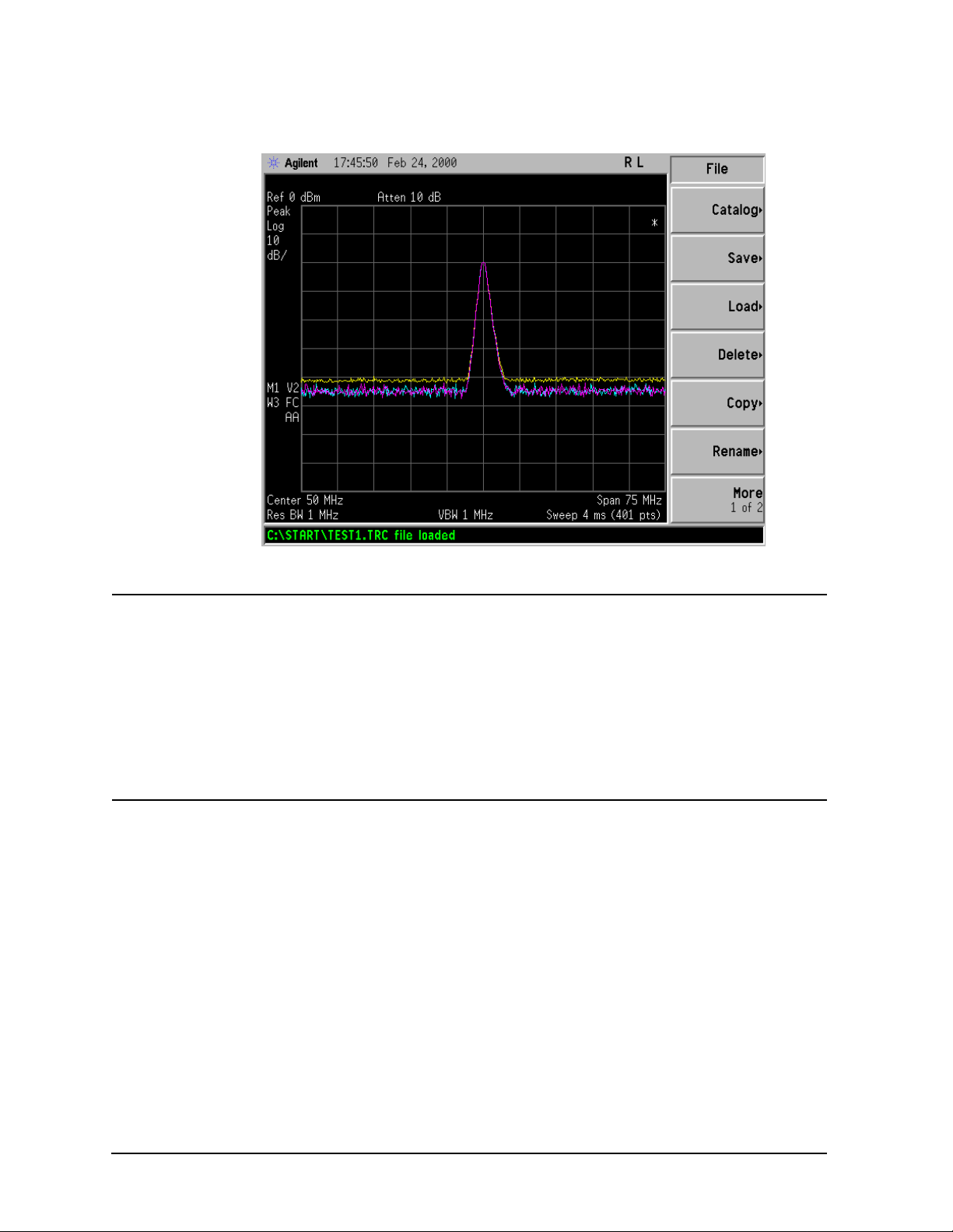
Viewing Catalogs and Saving Files
Saving a File
Figure 4-6. File Loaded
NOTE You should notice that the trace you saved, in this example trace 3, is loaded
to trace 2. If you wish to verify this conditi on, remove the signal input. For
Agilent E7401A, press Input/Output, Amptd Ref (Off), for all other models,
press Input/Output, Amptd Ref Out (Off).
Note that when a tr a ce is loaded, it is placed in view mode. To s ee that trace 2
is in view mode , bl an k t races 1 and 3 by pressin g
Trace 3, Blank. Then press Trace 2. Notice that trace 2 is the only trace
View/Trace, Trace 1, Blank,
displayed in view mode (the view key is selected, and the tr ace is not
sweeping). Your display should look similar to Figure 4-7.
58 Chapter 4
Page 59
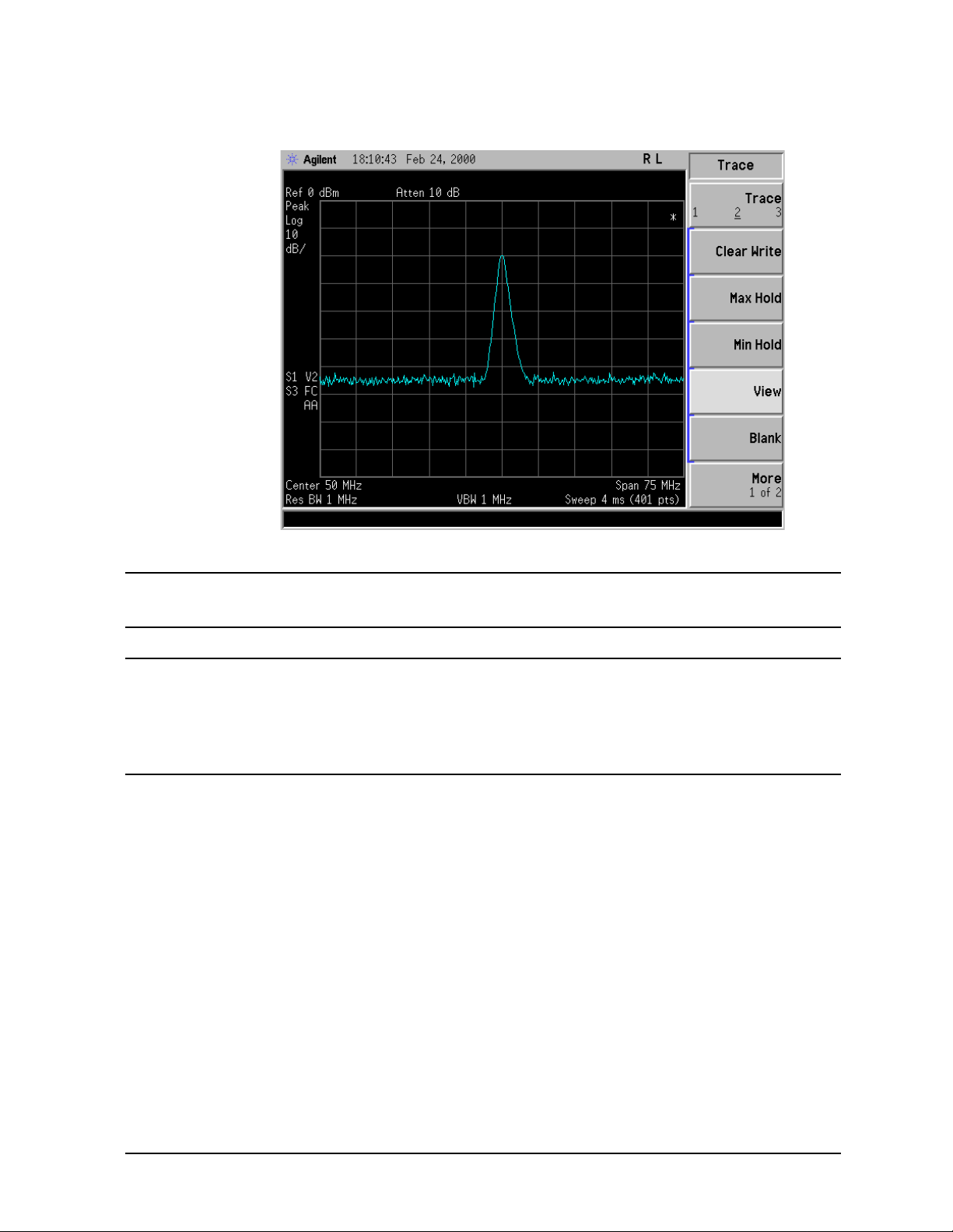
Figure 4-7. Ve rif ying T r ace 1
Viewing Catalogs and Saving Files
Saving a File
CAUTION When operating in dc coupled mode, ens ure protection of the input mixer by
limiting the input level to 0 Vdc and +30 dBm.
NOTE When loading Limits files, be sure you have selected the appropriate X Axis
Units: frequency or tim e (
Display, Limits, Properties, X Axi s Uni ts). If you are in
time X-A xis Units , an d yo u lo ad freque n c y l imits, all current limit lin e d ata
will be erased and the analyzer will switch to the frequency domain. The
reverse of the this situation also holds true.
Renaming a File
1. To access the Rename menu, press File, Rename.
2. Select the type of file you want to rename (setup, state, trace, limits, screens, or
corrections). In this example you are renaming a trace file; press
3. Select the drive and directory where your file is located. In this example, choose drive
C:\STAR T.
4. Select the file you want to rename. In this example, choose the file TEST1.TRC.
5. Press
Name to open the Alpha Editor menu. For this example, rename the fil e to RENAME
using the Alpha Editor softkeys. (The Name: field is limited to eight characters.) Your
display should look similar to Figure 4-8.
Type, Trace.
Chapter 4 59
Page 60
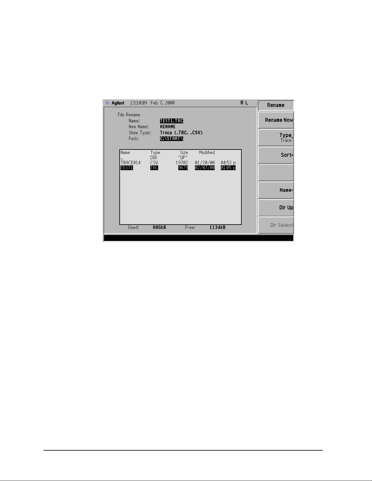
Viewing Catalogs and Saving Files
Saving a File
6. Press Enter, Rename Now: your file is now renamed and visible within the directory
displayed on your analyzer . The status line displa ys the message: C:\STA RT\ TES T1 .TR C
file rename d to C:\STA RT\RE NAME.T RC.
Figure 4-8. Renaming a File
60 Chapter 4
Page 61
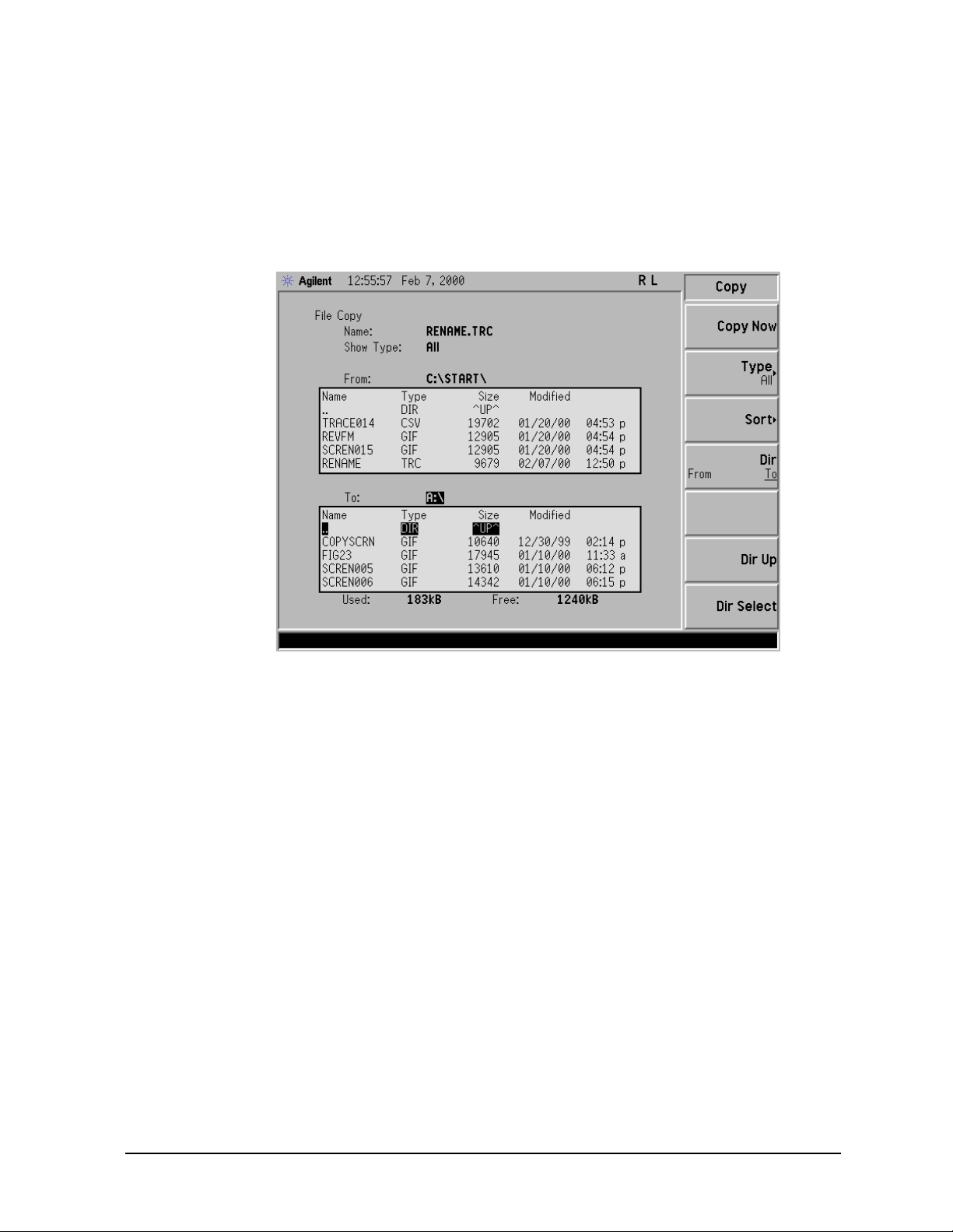
Viewing Catalogs and Saving Files
Saving a File
Copying a File
1. To access the Copy men u, pre ss File, Copy. This menu function brings up 2 directory
boxes as described by the From: and To: fields located dire ctly above the boxes. Refer to
Figure 4 -9.
Figure 4-9. Copy Menu
2. Pu t a fo rmatted floppy in the A: drive.
3. Select the type of file you want to copy (setup, state, trace, limits, screens, or
corrections). In this example you are copying a trace file from the C: drive to the A:
drive; press ,
4. Press
Dir (in the key menu) to underline From:. Notice the From: field (just above the
Type, Trace.
top directory box ) highlights the location from which y ou will be copying. Using the
navigation keys (Di r Up, Direct select, step keys, or front panel knob), locate the
C:\STAR T\ directory.
5. Scroll to highlight the file displayed in the directory box fro m which you wish to copy. In
this example, you wi ll need to highlight the fil e RENAME.
Chapter 4 61
Page 62

Viewing Catalogs and Saving Files
Saving a File
6. Press Dir (in the k ey menu) to underline To:. The To: field (jus t above the bottom
direc tory box) is highlighti ng the locati on to which yo u will be cop ying. Usin g t h e
navigation keys as described above, h ig hlight th e A:\ drive.
NOTE When pressing Dir (T o), the file chosen in the From: location is no longer
highlighted, however the Name: field above the From directory box displays
the chosen file; in this example: RENAME.TRC .
NOTE Highlighting a filename in the To: directory box has no significance. The file
cannot be placed inside another file.
7. Press
Copy Now to execute the operation. The message: “Copying f ile ” is displayed
during the copying proces s. Upon completion, the status ba r reads:
“C:\STAR T\R ENA ME .TR C f il e c opi ed” . You have now copied the file RE NAM E from the
C: drive to the A: d rive.
Deleting a File
1. To access the Delete menu, press File, Delete.
2. Select the type of file you want to delete (setup, state, trace, limits, screens, or
corrections). In this example, you are deleting a tra ce file; press
3. Select the drive and directory where the file you wish to delete is located. In this
example, choose C: \ST ART \. U se the na vigation keys (
Dir Up, Dir Select, step keys, front
panel knob) to highlight this location in the Path: field. (Refer to “Loca tin g and vie win g
files i n th e cat alog” on page 50 for more instructions.)
4. Select the file you want to delete. In this example, choos e the file RENAM E. TRC. Move the
cursor with the navigation keys to highlight the file name.
5. Press
Delete Now. The message: Del et ing fi le pops up on the display during the
operation. Upon completion, the status bar reads: C:\STAR T\R ENA ME .TR C f ile
deleted. Yo u r file is now d e leted and is no lo nger visible in the d ire ctory dis played on
your analyzer.
Ty pe, Trace.
62 Chapter 4
Page 63

Viewing Catalogs and Saving Files
Using the Alpha Editor
Using the Alpha Editor
The Alpha Editor enables you to select letters to enter a name for a file or directory (File,
Rename, for example).
1. Use the
More keys to display the softkey that lists the character you want. Each softkey
has several ch aracters on it.
2. W h e n you press a so ftkey, its characters are displayed on indivi du al softkeys.
3. Select the one you want.
Chapter 4 63
Page 64

Viewing Catalogs and Saving Files
Using the Alpha Editor
64 Chapter 4
Page 65

5 Options and Accessories
This chapt e r li st s o pt ion s an d accessories available for your analyzer.
65
Page 66

Options and Accessories
Ordering Options and Accessories
Ordering Optio ns and A ccess o ries
Options and accessories help you configure the analyzer for your specific applications, and
enable you to use the analyzer.
Options (see page 67)
All options are available when you order a spectrum analyzer; some options are also
available as kits that yo u can o rder and ins ta ll aft e r yo u receive th e an alyzer. Order kits
through your local Agilent Sales and Service Office.
At the time of analyzer purchase, options can be ordered using your product number and
the number of the option you are ordering. F or exampl e, if you are ordering Option 1D6 for
an Agilent E7401A, you would order E7401A 1D6.
If you know the option you wish to order, refer to See “Options” on page 67. which is in
ascending order by option number. T he options are described below, they are listed in
alphabetical order by name for your review, see “Option Descriptions” on page 68.
Accessories (see page 73)
Order acce sso ries through y our local Agilent Sa le s and Service Off ice .
66 Chapter 5
Page 67

Options
Option
Options and Accessories
E7401A
E7402A
E7403A
Options
E7404A
E7405A
060 (Standarda)
230
Low Emission •••••
Benchlink Web Remote Control Software
b
•••••
0B0 Delete Manual Set •••••
0B1 Addit ional Man ual Set •••••
0BV Service Documentation, Component Level •••••
0BW Service Documentation, Assembly Level •••••
1AX
RS-232 and Parallel Interface
c
•••••
1CP Rack Mount with Handles •••••
1D5 H igh Stability Frequency Reference •••••
1D6 Time-Gated Spectrum Analysis •••••
1DN 50 Ohm Tr acking Generator •••••
1DR (Standard) Narrow Bandwidths •••••
1DS (Standard) RF Preamplifier •••••
8ZE Refurbished units (as available) •••••
A4H (Standard) GPIB and Parallel Interface •••••
A4J
IF, Video and Sweep Ports
d
•••••
A5D DC Power Cable •••••
AXT Transit Case •••••
AYQ (S tan da rd) Q uas i-Peak De tect io n Card •••••
AYT Gray Soft Ca rrying Case •••••
AYU Yellow Carrying Case •••••
AYX
Fast TIme Domain Sweeps
e
•••••
B72 (Standard) Enhanced Memory, 12F/32D •••••
BAB APC 3.5 Input Connector •
UK6
Commercial Calibration
f
•••••
UK9 Front Panel Cov er •••••
Chapter 5 67
Page 68
Options and Accessories
Options
Option
E7401A
E7402A
E7403A
E7404A
E7405A
UKB Low Frequency Extension ••••
W32 3 Year Calibration Contract •••••
W50 5 Year Service Support •••••
W52 5 Year Calibration Contract •••••
a. Option 060 is standard for analyzers with a serial num ber great er than US41060000.
b. This option requires Option A4H or 1AX.
c. Option 1AX replace s the GPIB parallel with RS232 parallel. 1AX is not compatible with the Agilent
E7415A EMI Measurement Software.
d. Not compatible w ith option A YX.
e. N ot compatible with opti on A 4J.
f. This option is only available at time of purchase.
Option Descriptions
Each op t io n is de s cribed below in alphabetica l order.
12 Vdc Power Cable (Option A5D)
Option A5D provides a 12 Vdc power cable tha t allow s your analyzer to be pow ered from 12
V automotive or truck ba tteries.
3 Year Calibration Contract (Option W32)
Option W32 provides your analyzer with a 3 year analyzer calibration contract.
5 Year Calibration Contract (Option W52)
Option W52 provides your analyzer with a 5 year analyzer calibration contract.
5 Year Ser vi c e Su pp o rt ( Opt i o n W5 0)
Option W50 provides your a nalyzer with a total of 5 years of service support. This adds a
2 year se rvice contract t o the an alyzer’s base 3 year warr an t y.
50 Ohm Tracking Generator (Option 1DN)
Option 1DN provides a 9 kHz to 1.5 GHz built-in tracking generator for the Agilent
E7401A. Option 1DN provides a 9 kHz to 3 GHz built-in tracking gener ator fo r the Ag il ent
E7402A , E7403A, E7404A, and E7405A. This sour ce creates a source-r e ceiver co mbination
that allows insertion-loss, frequency response, and return-loss measurements. The
tracking generator ha s a wide distortion-free dynamic range, plus good sensitivity and
selectivity.
Additional Manual Set (Option 0B1)
Option 0B1 provides an ad ditional copy of the User’s, Calibration, S pecificatio n s , an d
Reference guides for you r in st ru ment.
68 Chapter 5
Page 69

Options and Accessories
Options
APC 3.5 In put Connector (Option BAB)
The type-N female connector is replaced with an APC 3.5 mm male connector. An APC 3.5
(f) to APC 3. 5 (f), and BNC (f) t o SMA (m) adapt ers are include d for alignme n t pu rpo s e s.
Benchlink Web Remote Control Software
(Option 230)
Option 230 provides software which can be used to control the analyzer remotely over the
web. When the analyzer is connected via GP-IB to one personal computer (PC), access to
the analyzer is availa ble through any internet connection b y specifying the IP address of
the physically connected PC. The following analyzer functions ar e available through
remote web access:
• front panel control
• capture screen images
• capture trace data
• remote programming commands (SCPI)
Commercial Calibration with Test Data
(Option UK6)
Option UK6 provides the factory calibration test data on a floppy d isk and the standard
commercial calibration certificate on the initial analyzer shipment.
Option U K6 is only avai lable at time o f pu rchase.
Component Level Service Documentation (Option 0BV)
Option 0BV provides a copy of the Agilent ESA/EMC Spectrum Analyzers
Compon en t-Level Information. The compone n t - le vel information includes parts list s ,
compone n t -location diag rams, and sche matic diagrams for selected assemblies.
Delete Manual Set (Option 0B0)
Option 0B0 deletes copies of the User’s, Calibration, Programmer’s, Specific at io ns,
Measurement guides.
Enhanced Memory Upgrade (Option B72)
Option B72 provides 2 SIMMS which increases the analyzer’s RAM to 32 MBytes and its
flash or data storage memory to 16 MBytes (10 MBytes of which are av ailable to the user
for data storage and measurement personalities).
Chapter 5 69
Page 70

Options and Accessories
Options
Fast Digitized Time Domain Sweeps (Option AYX)
Option AYX allows fast digitized sweep t im e s as fast as 5 µsec in spans of 0 Hz. Refer to
Sweep key description in your User’s guide for infor mation about possible sweep times.
the
It also provides the following additional inputs and outputs:
Option AYX - provides the analyzer with additional inputs and outputs. T hey are as
follows: SWP OUT , HI SWP OUT (TTL), HI SWP IN (TTL), AUX VIDEO OUT , and AUX IF
OUT.
SWP OUT - sweep ramp output, provides a voltage ramp proportional to the sweep of
the analyzer (0 V to 1 0 V).
HI SWP OUT (TTL) - provides the HI SWP TTL signal as an output (TTL high during a
sweep, TTL low during a retrace). It indicates when the analyzer is sweeping
HI SWP IN (TTL) - allows external sweep control. It can b e grounded to stop and reset
the sweep.
AUX VIDEO OUT - provides detected video output (before the analog-to-digi tal
conversion) proportional to vertical deflection of the trace.
AUX IF OUT - provides a 50 Ω, 21.4 MHz IF output that is the down-converted signal of
the RF input of the a nalyzer.
Front Panel Protective Cover (Option UK9)
The cover assembly snaps onto the front of your analyzer to protect the front panel during
travel and when the unit is not in use. The front panel protective cover includes a storage
compartment to house small accessories or cables.
GPIB and Parallel Interface (Option A4H)
Option A4H allows you to control your analyzer from a computer that uses a general
purpose interface bus (GPIB). Option A4H includes a GPIB connector, a parallel interface
1
connecto r fo r printers, a CD -R OM containin g I n tui Link Toolbar software
, and the
Programmer’s guid e fo r yo ur analyzer.
Option A4H allows the analyzer to copy its display to a printer connected to the parallel
interface co nnector.
Hard Transit Case (Option AXT)
Option A XT provides a har d tr an sit case. The hard transit case wi ll s ur vi ve co mmercial
transportation. Thi s rugged case has two wheels and an extend ible handle for easy
transport. The case can also accommodate two battery packs and ac adapters.
1. This program allows you to download spectrum analyzer display or data files to a personal computer
using Microsoft Word or Microsoft Excel. IntuiLink Toolbar installation instructions are included
with the CD-ROM.
70 Chapter 5
Page 71

Options and Accessories
Options
High Stability Frequency Reference (Option 1D5)
Option 1D5 improves the freq uency reference accuracy. The analyzer’s synthesizer is
phase locked to an oven controlled crystal oscillator (OCXO), i nstead of the standard
VCXO. When present with narrow resolution bandwidth (Option 1DR) it provides 1 Hz
and 10 Hz r es ol ut io n bandwidths.
IF, Sweep and Video Ports (Option A4J)
Option A4J provides the analyzer with additional inputs and outputs . They are as f oll ows:
SWP OUT, HI SWP OUT (TTL), HI SWP IN (TTL), AUX VIDEO OUT, and AUX IF OUT.
SWP OUT - sweep ramp output, provides a voltage ramp proportional to the sweep of the
analyz e r (0 V to 10 V).
HI SWP OUT (TTL) - provides the HI S W P TTL signal as an o u t p u t (TTL high during a
sweep, TTL low during a retrace). It indicates when the analyzer is sweeping.
HI SWP IN (TTL) - allows external sweep control. It can b e grounded to stop sweeping.
AUX VIDEO OUT - provides detected video output (before the analog-to-digi tal
conversion) proportional to vertical deflection of the trace.
AUX IF OUT - provides a 50 Ω, 21.4 MHz IF output that is the down-converted signal of
the RF input of the a nalyzer.
Low Emission (Standard)
Option 060 provides reduced radiated and conducted emissions to comply with EN55011
Class B requirements. This option appli es during ac operati on only. Option 060 is standard
for anal yzers with a ser ial n u mber greate r than US4106 0000.
Low Frequency Extension (Option UKB)
Option UKB extends the frequency range of the analyzer on the low end to 100 Hz when
DC coupling is selected. This option is available on EMC models E7402A, E7403A,
E7404A , an d E 7405A.
Narrow Res ol u ti o n Ba nd wi d th
(Standard)
This option provides addit ional narro w resolution bandw idths of 10 Hz, 30 Hz, 100 Hz, and
300 Hz and 200 Hz EMI. These bandwidths improve the analyzer s ensitivity and allow you
to resolve closely spaced signals, as well as allow y ou to make CISPR Band A
measurements.
Operating and Carrying Cases (Option AYT/A YU)
Options AYT and AYU are protective soft operating and carrying cases. Option AYT is
made of gray rip-stop nylon and Option AYU is made of yellow rip-stop nylon. An outside
pocket holds manuals or other accessories. A reinforced adjusta ble padded shoulder strap
provides ergonomic distri bution betwee n your hand and shoulder. The front and rear pane l
soft covers adjust to be compatible with the front panel protectiv e hard cover (Option UK9)
and snap on battery pack (Agilent E1779A). Side ventilation allows for operation without
removal, but the maximum operating temperature is reduced to 45 °C.
Chapter 5 71
Page 72

Options and Accessories
Options
Pre-amplifier (Standard)
The pre-amplifier improves the analyzer’s sensitivity (lowers the noise floor) by
approximately 16 dB . P re -amplifier frequency ran g e: the Agilent E 7401A (100 kHz to
1.5 GHz), for the Agilent E7402A, E7403A, E7404A, and E7405A (1 MHz to 3 GHz) with a
nominal gain of 20 dB.
Rack Mount Kit With Ha ndles (Option 1CP)
Option 1CP provides the parts necessary to mount the analyzer i n a standard 19 inch
(482.6 mm ) e qu ipment rack. It in cludes front han dles and rack slide s fo r added
convenience. Rack mount height is 8.75 in (222.3 mm).
RS-232 and P arallel Interface (Option 1AX)
Option 1AX allows you to control your analyzer from a computer that uses an RS-232
interface . It in cludes a 2.5 me t e r 9-pin (f) to 9-pin (f) connector RS-232 cable (Agilent
5182-47 94), a parallel in t e rface connect o r fo r printers, a C D-ROM cont ain ing IntuiLink
1
Toolba r s o ftware
, and the Programmer’s guide for your analyzer.
Option 1AX allows the ana lyzer to copy its display to a printer.
Service Documentation and Performan ce Verification and Adjustment Software
(Option 0BW)
Option 0BW provides a c opy of the Agil en t E M C Spectrum Ana ly z ers Service Guid e and
PC-based performance verification and adjustment software on CD-R OM. The service
guide describes a ssembly level troubleshooting procedures, provides a parts list, and
documents the adjustment p rocedures.
Time-Gated Spectrum Analysis (Option 1D6)
Option 1D6 allows you to selectively measure the spectrum of signals that may overlap in
the frequency domain, but are separated in the time domain. By adjusting a time gate
based on a user-supplied trigger signal, you can significantly increase the diagnostic
capability of your spectrum analyzer for time-interlea v ed signals.
1. This program allows you to download spectrum analyzer display or data files to a personal computer
using Microsoft Word or Microsoft Excel. IntuiLink Toolbar installation instructions are included
with the CD-ROM.
72 Chapter 5
Page 73

Options and Accessories
Accessories
Accessories
A number of accessories are available from Agilent Technologies to help you config ure your
analyzer for your specific applications. They can be ord ered through your local Agilent
Sales an d S e rvice Office an d are listed be lo w.
AC Probe
The Agilent 85024A high frequency probe performs in-circuit measurements without
adversely loading the circuit under test. The probe has an input capacitance of 0.7 pF
shunted by 1 M Ω of resistance and operates over a frequency range of 300 kHz to 3 GHz.
High probe sensitivity and low distortion levels allow measur ements to be made while
taking advantage of the full dynamic range of the spectrum analyzer.
The Agilent 41800A low frequency probe has a low input capacitance and a frequency
range of 5 Hz to 500 MHz.
Antennas
11955A biconical antenna. Frequency range from 30 to 300 MHz.
11956A log periodic antenna. Frequency range from 200 MHz to 1 GHz.
Broadband Preamplifiers and Power Amplifiers
Preamplifiers and power a mplifiers can be used with your spectrum analyzer to enhance
measurements of very low-level signals.
• The Agilent 8447D preamplifier provides a minimum of 25 dB gain from 100 kHz to
1.3 GHz.
The Agilent 87405A prea mp lifier provides a minimum of 22 dB gain from 10 MHz to
3 GHz. (Power is supplied by the probe power output of the analyzer.)
• The 11909A l ow noise preamplifier provides a minimum of 32 dB gain from 9 kHz to
1 GHz and a typical noise figure of 1.8 dB.
Carrying Strap (Part Number E4401-60028)
This carrying strap comes with Option s AYT and AY U. It can al so be o rde re d separately
and used with Agilent EMC analyzers.
Close Field Probes
11940A cl ose field probe (9 kHz - 30 MHz)
11941A cl ose field probe (30 MHz - 1 GHz)
These probes are desig ned to measure magnetic field radiation from surface currents,
slots, and cables. The probes are part of a close-fiel d probe set (11945A). The set also
inclu de s cables and adap t e rs.
Chapter 5 73
Page 74

Options and Accessories
Accessories
External Keyboard
You may use any IBM AT compatible keyboard with a mini DIN c onnector. Screen titles
and filenames can be entered with the external keyboard.
GPIB Cable
For use with Option A4H (standard). The Agilent 10833 Series GPIB cables interconnec t
GPIB devices and are available in four different lengths. GPIB cables are used to connect
controllers to a spectrum analyzer.
Agilent E1779A Battery Pack
The E1779A is a battery pack that will power an Agilent analyzer for 80 to 114 minutes,
depending on the options installed in the analyzer. Refer to the E1779A Battery Pack
User’ s Guide for more informatio n .
Line Impedance Stabilization Network (LISN)
119 67D line impedance stabilization network (LISN ) is used for commercial conducted
measurements. The LISN ha s a maximum current of 10 amps. The LISN com es with a
standard NEMA connector, or option 001 (SCHU KO connector) or option 002 (British
connector).
Parallel Interface Cable
For use wit h Opt i o n A4 H an d 1AX. A 36-pin to 25-pin male-to -male 2 meter cable can be
used to connect sup ported printers to an analyzer. This cable must be IEEE-1284
compliant.
Printer
For use with Option A4H or 1AX. The DeskJet personal printers provide black and
white or colo r pri n t ing fo r another form of permanent reco rds o f y our test results. The HP
LaserJet series printers are also compatible. The printers connect to the parallel interface
installed on the analyzer with either Option A4H (standard) or 1AX.
RF and T ransient Limiters
The Agilent 11867A and 11693A RF Limiters protect the analyzer inp ut circuits from
damage due to high power levels. The 11 867A operates over a frequency range of d c to
1800 MH z an d be g in s re flecting sign al levels over 1 mW up to 10 W average power and
100 watts peak power. T h e 11693A microwave limiter (0.1 to 12. 4 GHz , us able to 18 GHz)
guards against input signals over 1 milliwatt up to 1 watt average power and 10 watts
peak power.
The Agilent 11947A Transient Limiter protects the analyzer inp ut circuits from damage
due to signal trans ients. It specifically is needed for use with a line impedance
stabilization network ( LISN). It oper ates over a frequency range of 9 kHz to 200 MHz, wit h
10 dB of insertion loss.
74 Chapter 5
Page 75

Options and Accessories
Accessories
RF Bridges
The Agil e n t 86205A 50 Ω RF bridge and 86207A 75 Ω RF bridge can be used to make
reflection measurements using an an alyzer with trackin g generator Option 1DN or 1DQ or
with an e xte rn al signal gene rat o r. These exter n al directional bridges offer hig h dire ctivity
and excellent port match. The 86205A operates over a frequency range of 300 kHz to 6
GHz. The 86207A operates over a frequency range of 300 kHz to 3 GHz.
RS-232 Cable
THE FOLLOWING NEEDS ATTENTION REGARDING THE AVAILABLE CABLES.
PERHAPS FRANCIS CAN BE OF ASSIST ANCE.
For use with Option 1AX. The 24542G is a 3 meter 9-pin (f) to 25-pin (m) RS-232 cable. The
HP 24542U is a 3 meter 9-pi n (f ) to 9-pin (f) RS-232 ca ble for serial 9-pin PC co n n e ct io n to
an analyzer. The modem cable required is HP 24542M 9-pin (f) to 25-pin (m), and the PC
cable is HP 24 542 U. T he Ag ile nt 51 82 -47 94 is a 2. 5 met er 9- p in ( f) to 9-p in ( f) R S- 232 c able
for serial 9-pin PC c onnection to an analyzer (included w ith Option 1AX).
Tripod
The 1968C is a non-metallic antenna tripod. Unwanted reflections are minimized in the
test environment because of the tripods non-metallic design.
Chapter 5 75
Page 76

Options and Accessories
Accessories
76 Chapter 5
Page 77

6 In Case of Difficulty
This cha p t e r in cludes info rmation on how to check fo r a pro blem with y our Agilent
Technologies spectrum analyzer, and how to return it for service.
If you experience a problem or would like additional information about your analyzer,
Agilent Technologies’ worldwide organiza tion is ready to provide the sup port you need.
77
Page 78

In Case of Difficulty
Before calling Agilent Technologies, however (or returning an analyzer for service),
perform the quick checks listed in “Check the Basics” on page 80. This check may
eliminate the problem.
If a problem persis ts, you may choose to:
• Repair the analyzer yours elf. See “Service Options” on page 81.
• Return the analyzer to Agilent Technologies for repair. See “Returning an Analyzer for
Service” on page 82, fo r more infor mation.
WARNING No operator serviceable parts inside. Refer servicing to qualified
personnel. To prevent electrical shock, do not remove covers.
NOTE If the analyzer is still under warranty or is cover ed by a maintenance
contract , it w il l be re paired under the t e rms of the warran t y or plan (the
warranty is located at the front of this manual).
If the analyzer is no longer under warranty or is not covered by an Agilent
Technologies maintenance plan, Agilent Technologies will notify you of the
cost of the repa ir after examining the analyzer.
78 Chapter 6
Page 79

In Case of Difficulty
Types of Spectrum Analyzer Messages
Types of Spectrum Analyzer Messages
The analyzer can generate various messages that appear on the display during op eration.
For a complete list of spectrum an al yze r messages, see the I nst ru ment Messages an d
Functional Tests manual. The following table describes the four types of spectrum
analyzer m e ssages.
T able 6-1 Types of Messages
Type of Message Location Notes
Informat ional messages
typically provide verification
that an action has occurred. In
general, no user intervention is
required.
Pop-up message s pro m p t yo u
to verify that an action will be
performed or tell you that an
action is currently being
performed.
Status mes sag es indicat e a
condition that m ay result in
erroneous data being di splayed .
Multiple sta tus m e ssages may
be displayed at the same time.
User Error messages appear
when an attempt has been
made to set a parameter
incorrectly or an operation has
failed (such as saving a file).
Bottom of the
display in the
status line (in
green on analyzer s
with a color
display).
Middle of the
display in a
framed box.
Right side of the
display and/or in
the SCPI Status
Register system.
Bottom of the
display in the
status line (in
yellow on
analyzers with a
color display) and
in the SCPI Error
Queue.
Messages will rema in until the
mess a ge is cl eared by press i ng
Esc or Preset, or is overwritten
by another message.
Mess age remains un til you
acknowledge the prompt, or the
action is completed.
Most messages remain only
until the erron eou s cond ition is
corrected.
Messages remain until you
clear the error (press
Show Errors, Clear Error Queue
or another message is displayed
in the status line.
Pressing the
will clear error mess ages f rom
the display, but the messages
will remain in the err or q ueue .
Esc or Preset keys
System,
),
Chapter 6 79
Page 80

In Case of Difficulty
Before Call ing Agi lent Technologies
Before Cal li ng Agile nt Technologies
Check the Basics
❏ Is there po we r at the receptac le ?
❏ Is the analyzer turned on? Listen for internal fan nois e to determine if the analyzer
cooling fan is runni ng. Feel the right side of the analyzer to feel for air flow.
❏ If other equipment, cables, and connec tor s ar e b eing us ed with yo ur sp ec tr um analyzer,
make sure they are connected properly and operating correctly.
❏ Review the measurement procedures b eing performe d when the prob lem first a ppeared.
Are all of the settings correct?
❏ If the analyzer is not functioning as expected, return the analyzer to a known state by
pressing
Preset, and Factory Preset (if displayed).
NOTE Some analyzer settings are not affected by a Preset. If you wish to reset the
analyzer configuration to the state it was in when it was originally sent from
the factory, press
System, Power On /Preset, Preset Type, Factory. Then pre s s
the green Preset hardkey on the fr ont panel.
❏ Is the measurement being performed, and the results that are expected, within the
specifications and capabilities of the analyzer? Refer to the Specifications guide for your
analyzer.
❏ T o meet specifica tions, the anal yzer must be alig ned. Either t he Auto Align (On) fea ture
must be select e d (press
System, Alignments, Auto Align, On), or the analyzer must be
manually aligned at leas t once every hour (see your specif ications guide for more
information), or whenev er the temperature changes more than 3°C. When
On is selected, the AA screen annotation appears on the left edge of the display.
❏ Perform an Alignment. Press
System, Alignments, Align Now, All.
❏ If the previously performed alignments did not resolve the problem, press
Alignments, Load Defaults. Then press System, Alignments, Align Now, All.
Auto Align,
System,
❏ Is the anal yz e r di splaying an error message? If so, refer to the Instrum e n t M es sages
and Functional Tests manual.
❏ If the necessary equi pment is available, perform the functional tests in the Instrument
Messag e s an d Functional Tests document for you r an alyzer.
80 Chapter 6
Page 81

In Case of Difficulty
Before Calling Agilent Technologies
Read the W arranty
The warranty for your analyzer is on page 22. Please read it and becom e familiar with its
terms.
If your analyzer is covered by a separate maintenance agreement, please be familiar with
its terms .
Service Options
Agilent Technologies offers several optional maintenance plans to service your analyzer
after the warranty ha s e xpi re d. C all your Agil e n t Technologies office for full de ta il s.
If you want to service the analyzer yourself after the warranty expires, you can purchase
the service documentation that provides all necessary test a nd maintenance information.
You can order the service documentation, Opti on 0BW (assembly level troubl esho oting a nd
adjustment software) through your Agilent Technologies office.
Calling Agilent Technologies
Agilent Technologies has offic es a ro und the w orld to provide you with complete support for
your analyzer. To obtain servicing information or to order replacement parts, contac t the
nearest Agilent Technologies office listed in the table below. In a ny correspondence or
telephone conversations, refer to your analyzer by its p roduct number, f ull serial number,
and firmware revision.
Press
System, More (1 of 3), Show System, and the produ ct number, se ri al n u mber, and
firmware revision inform ation will be displayed on your a nalyzer screen. A serial number
label is also attached to the rear panel of the analyzer.
Table 6-2. Contacting Agilent Technologies
Online assistance: www.agilent.com/find/assist
United S t ates
(tel) 1 800 452 4844
Canada
(tel) 1 877 894 4414
(fax) (905) 282-64 95
Europe
(tel) (31 20) 547 2323
(fax) (31 20) 547 2390
Latin America
(tel) (305) 269 750 0
(fax) (305) 269 7599
Japan
(tel) (81) 426 56 7832
(fax) (81) 426 56 7840
Australia
(tel) 1 800 629 485
(fax) (61 3) 9210 5947
New Zealand
(tel) 0 800 738 378
(fax) 64 4 495 8950
Asia Pacific
(tel) (852) 3197 7777
(fax) (852) 2506 9284
Chapter 6 81
Page 82

In Case of Difficulty
Returning an Analyz er for Service
Returning an Analyzer for Service
Service Tag
When you are returning an analyzer to Agi l ent Technologies f or serv ice, f i ll out a nd atta c h
one of the blue service tags provided at the end of this chapter. P lease be as specific as
possible about the problem. If you have recorded any error messages that appeared on the
display, have completed a functional test, or have any other specific data on the
performance of your a nalyzer, p lease include a copy of this information.
Original Packaging
Before shipping, p ack the unit in the original factory packaging materials if they are
available. If the original materials were not retained, see "Other Packaging" (below).
NOTE Install the trans portation disk into the floppy d rive to reduce the possibility
of damage during transportation. If the original tra nsportation disk is not
available , a blank floppy may be substitu t e d.
Other Packaging
CAUTION Analyzer damage can result f r om us ing p a ckagi ng materi a ls other than those
specified. Never use styrene pellets in any shape as packaging materials.
They do not adequately cushion the equipment or prevent it fr om shifting in
the carton. They cause equipment damage by g enerating stati c electr icity and
by lodging in the ana lyzer louvers, blocking airflow.
You can repackage the analyzer with commercially available materials, as follows:
1. Attach a completed service tag to the analyzer.
2. Install the transportation disk or a blank floppy disk into the disk drive.
3. Wrap the an alyzer in antistatic plas tic t o r educe the poss ibi lity of damage caused by
electrostatic disc harge.
4. U se a st ro n g shipping contain e r. The carton must be both large enou g h an d st ro n g
enough to accommodate the analyzer. A double- walled, corrugated cardboard carton
with 15 9 kg (350 lb) burst i n g st re n gth is adequ at e . Al lo w at least 3 to 4 inch e s o n al l
sides of the an alyzer for packing m at erial.
5. Surround the equipment with thr ee to four inches of packing material and prevent the
equipment from moving in the carton. If packing foam is not available, the best
alternative is S.D.-240 Air Cap™ from Sealed Air Corporation (Hayward, California,
94545). Air Cap looks lik e a plastic sheet filled with 1-1/4 inch air bubbles. Use the
pink-colored Air Cap to reduce static electrici ty. Wrapping the equipment several times
in this material should both protect the equipment and prevent it from moving in the
carton.
82 Chapter 6
Page 83

In Case of Difficulty
Returning an Analyz er for Service
6. Seal the shipping container securely with strong nylon adhesive tape.
7. Mark the shipping container “FRAGILE, HANDL E WITH CAR E ” to assure careful
handling.
8. Retain copie s o f all shipping papers.
Chapter 6 83
Page 84

In Case of Difficulty
Returning an Analyz er for Service
84 Chapter 6
Page 85

Index
Numerics
10 MHz REF INPUT
10 MHz REF OUTPUT
50 ohm RF bridge
75 ohm matching transformer
75 ohm RF bridge
A
AC probe
Accessories
carrying strap
accessories
AC probe
Antennas
antennas
battery pack
broadband preamplifiers
Close Field Probes
close field probes
External Keyboard
GPIB cable
Line Impedance Stabilization
LISN
Parallel Interface Cable
printer
RF bridge
RF limiters
RS-232 cable
transient limiters
Tripod
tripod
active function
Agilent Technologies, calling
alignments, internal
alpha editor, using
amplifiers
Amplitude key
AMPTD REF OUT
analyzer battery
annotation
antenna
antennas
application information
arrow keys
arrow keys, using
AUX IF OUT
AUX VIDEO OUT
B
battery
analyzer
battery information
battery pack
Benchlink Web Remote Control
, 73
, 73
, 73
, 73
, 73
, 74
Network (LISN)
, 74
, 74
, 75
, 74
, 75
, 75
, 73
, 28
, 73
, 73
, 26
, 34
, 13
, 74
Software
, 69
, 34
, 34
, 75
, 74
, 75
, 73
, 74
, 73
, 73
, 73
, 74
, 74
, 74
, 75
, 74
, 36
, 81
, 17
, 63
, 24
, 26
, 13
, 2
, 41
, 34
, 13
broadband preamplifiers
C
cable
GPIB
, 74
parallel interface
RS-232
carry in g strap
Catalog Menu
catalogs
naming
checking the fuse
clock, battery
close fiel d pr obe
Clos e F i el d Probe s
connector
10 MHz ref input
10 MHz ref output
aux if output
aux video output
ext tri g in pu t
external keyboard
GPIB
hi sweep in
hi sweep out
INPUT 50 ohm
parallel interface
probe pow e r
RF OUT 50 ohm
RS-232
service
CONTROL functions
copy files
D
data cont ro l s
data keys
data, entering from front panel
DC Fuse
DC probes
use of
delete files
Dir Sel e ct ke y
Dir Up key
directory
creating
disk format
display, information scree n
documentation
CD-ROM
standard set
down arrow key
E
earphone co nnector
, 75
, 73
, 51
, 63
, 10
, 13
, 73
, 34
, 33
, 33
, 34
, 33, 34
, 27
, 26
, 33
, 32
, 61
, 25
, 26
41
, 35
, 73
, 62
, 52
, 52
, 52
, 53
, 7
, 7
, 26
, 73
, 74
, 73
, 34
, 34
, 34
, 26
, 33
, 27
, 25
, 15
, 25
electrostatic discharge (ESD)
protecting again st
EMI
Low Emission (Option 060)
Enter key, using
Esc key
escape key
examples
EXT KEYBOARD
EXT TRIG IN
External Keyboard
external keyboard connector
external reference
F
factory preset, description
features
file copying
file deleting
File key
file menu functions
file renaming
file saving
files
firmware upg rade informatio n
floppy di sk format
format a disk
frequency accu racy, increasing
frequency count, using
,
Frequency Extension Assem bly
Frequency key
front panel
front panel features
fuse
fuse holder
fuse location
G
GATE TRIG/EXT TRIG IN (TTL)
GATE/HI SWP OUT (TTL)
GPIB
GPIB cable
GPIB connector
, 24
frequency accuracy
signals, viewing
front pan e l
, 25
copy
, 61
delete
, 62
format
, 53
rename
save
, 54, 56, 57
naming
34
entering data
symbols
, 10
33
, 70
, 41
, 24
, 33
, 24
, 61
, 62
, 59
, 59
, 54, 56, 57
, 63
, 53
, 24
, 41
, 37
, 32
, 32
, 74
, 33
, 21
, 71
, 46
, 43
, 26
, 74
, 26
, 16
, 42
, 50
, 2
, 53
, 46
, 46
,
, 24
,
, 33
Index 85
Page 86

Index
H
Help key
HI SWEEP IN
HI SWEEP OUT
hold key
I
information screen
information, additional
INPUT 50 ohm
instrument preset
interface bus
GPIB
RS-232
internal alignments
K
key overview
keypad, using
knob
knob, using
L
limiters
RF and transient
line fuse
line impedance stabiliza tion
Line Impedance Stabilization
LISN
Load key
M
manuals, standard set
marker
frequency and amplitude,
moving
turning off
marker annotation
change with frequency count
location
MARKER functions
Measure key
Media Door
Menu keys
menu keys
monitor output
N
Navigation keys
, 27
, 34
, 33, 34
, 24
, 15
, 2
, 27
, 25
, 70
, 72
, 17
, 36
, 41
, 25
, 41
, 74
, 32
network
Network (L IS N)
, 74
, 74
, 74
, 25
, 7
reading
to peak
to reference level
with knob or arrow key
, 44
, 44
, 44
, 47
, 44
, 25
, 25
, 25
, 24
, 36
, 32
, 52
, 44
, 46
Next Window key
number/units keypad
numeric keypad, using
O
on/off switch
Option 1AX
Options
RS-232 and parallel inte rface
72
ordering options
overview, keys and key menus
P
, 42
, 42
, 25
, 74
label
, 13
Software
, 72
, 82
, 70, 72
, 37
, 75
, 25
packaging
Parallel Interface Cable
parallel interface connector
power amplifiers
power in put
power on key
preamplifiers
preset
factory
types
user, creating
Print key
printer
printer conne ctor
parallel
printer cont rol
printer setup
probe power con n ector
probe, close field
probes
AC and DC
product information
R
rear panel
symbols
rear panel features
rear-panel battery information
reference level, setting
remote control
Benchlink Web Remote Control
rename files
Return key
RF bridge
RF limiters
RF OUT 50 ohm
RPG knob
RPG, using
RS-232
RS-232 Cable
, 27
, 26
, 41
, 14, 27
, 72
, 68
, 74
, 33
, 73
, 32
, 14, 27
, 73
, 42
, 25
, 18
, 26
, 73
, 73
, 2
, 32
, 44
, 69
, 59
, 26
, 74
, 27
, 41
, 75
,
, 36
RS-232 cable
RS-232 interface connector
S
save files
Save key
screen annotation
screen, information
service connector
service op tions
signals, increasing accuracy
signals, v iewi n g
softkeys, auto and man mode
softkeys, basic types
Span key
speaker on/ off control
speaker vol u m e control
step keys
sweep output connector
SWEEP OUT
symbols in tit les
symbols, on front and rear panels
37
System k e y
T
Tab Keys
text, en tering
titles, editing
transient limite r
Tripod
tripod
U
unit softkeys, using
up arrow key
URL, PSA analyzers
URL, sales and service
user preset
creating
description
disabling
V
VGA connector
video connector
Viewing Angle keys
volume contro l
VOLUME knob
W
warm-up time
warranty
, 75
, 33
, 54, 56, 57
, 25
, 28
, 15
, 32
, 81
, 46
, 43
, 41
, 41
, 24
, 25
, 26
, 26
, 34
, 63
, 25
, 27
, 63
, 63
, 74
, 75
, 75
, 41
, 26
, 2
, 81
, 42
, 42
, 42
, 32
, 32
, 24
, 26
, 26
, 15
, 81
,
86 Index
 Loading...