


User’s Guide
HP V8486A Power Sensor
Serial Number Prefix:
US3901
HP Part No. 08486-90131
Printed in USA
January 1999
© Copyright 1999 Hewlett-Packard Company

HP V8486A Power Sensor
ii User’s Guide

Contents
1. HP V8486A Power Sensor
General Information . . . . . . . . . . . . . . . . . . . . . . . . . . . . . . . . . . . . . . . . . . . . . . . . . . . . . .3
Warranty. . . . . . . . . . . . . . . . . . . . . . . . . . . . . . . . . . . . . . . . . . . . . . . . . . . . . . . . . . . . . .3
Description . . . . . . . . . . . . . . . . . . . . . . . . . . . . . . . . . . . . . . . . . . . . . . . . . . . . . . . . . . . .3
Accessories . . . . . . . . . . . . . . . . . . . . . . . . . . . . . . . . . . . . . . . . . . . . . . . . . . . . . . . . . . . .4
Specifications . . . . . . . . . . . . . . . . . . . . . . . . . . . . . . . . . . . . . . . . . . . . . . . . . . . . . . . . . .5
Calibration Factor (CF) . . . . . . . . . . . . . . . . . . . . . . . . . . . . . . . . . . . . . . . . . . . . . . . . . .6
Installation. . . . . . . . . . . . . . . . . . . . . . . . . . . . . . . . . . . . . . . . . . . . . . . . . . . . . . . . . . . . . .8
Initial Inspection . . . . . . . . . . . . . . . . . . . . . . . . . . . . . . . . . . . . . . . . . . . . . . . . . . . . . . .8
Storage and Shipment . . . . . . . . . . . . . . . . . . . . . . . . . . . . . . . . . . . . . . . . . . . . . . . . . . .9
Operation . . . . . . . . . . . . . . . . . . . . . . . . . . . . . . . . . . . . . . . . . . . . . . . . . . . . . . . . . . . . . .10
Operating Environment. . . . . . . . . . . . . . . . . . . . . . . . . . . . . . . . . . . . . . . . . . . . . . . . .10
Operating Precautions . . . . . . . . . . . . . . . . . . . . . . . . . . . . . . . . . . . . . . . . . . . . . . . . . .10
Power Meter Calibrations . . . . . . . . . . . . . . . . . . . . . . . . . . . . . . . . . . . . . . . . . . . . . . .12
Power Measurements. . . . . . . . . . . . . . . . . . . . . . . . . . . . . . . . . . . . . . . . . . . . . . . . . . .12
Operating Instructions. . . . . . . . . . . . . . . . . . . . . . . . . . . . . . . . . . . . . . . . . . . . . . . . . .14
Modulation Effects . . . . . . . . . . . . . . . . . . . . . . . . . . . . . . . . . . . . . . . . . . . . . . . . . . . . .14
Linearity Correction. . . . . . . . . . . . . . . . . . . . . . . . . . . . . . . . . . . . . . . . . . . . . . . . . . . .15
Performance Tests . . . . . . . . . . . . . . . . . . . . . . . . . . . . . . . . . . . . . . . . . . . . . . . . . . . . . . .16
Replaceable Parts . . . . . . . . . . . . . . . . . . . . . . . . . . . . . . . . . . . . . . . . . . . . . . . . . . . . . . .17
Repair and Adjustments . . . . . . . . . . . . . . . . . . . . . . . . . . . . . . . . . . . . . . . . . . . . . . . .17
Warranty . . . . . . . . . . . . . . . . . . . . . . . . . . . . . . . . . . . . . . . . . . . . . . . . . . . . . . . . . . . . . .19
iii

Contents
iv

1 HP V8486A Power Sensor
1

HP V8486A Power Sensor
User’s Guide
Figure 1-1 HP V8486A Power Sensor with Accessories and Hardware
2 Chapter 1

HP V8486A Power Sensor
User’s Guide
General Information
This Operating Manual contains information about initial inspection and
operation of the HP V8486A Power Sensor.
Warranty
The Power Sensor is warranted and certified as indicated on the last
page of this manual. Do not open the Power Sensor. Any attempt to
disassemble the Power Sensor will void warranty.
Description
The HP V8486A is a diode-based power sensor. It measures power levels
in a range from −30 dBm to +20 dBm. (Specifications for the Power
Sensor are in Table 1-1.) The HP V8486A measures at frequencies from
50 GHz to 75 GHz.
The power is determined from the ac voltage developed across the
waveguide termination from the microwave source. The diodes convert
this ac voltage to dc. The dc voltage produced is proportional to the
square of the ac voltage. The dc voltage thus generated is a very low-level
voltage and requires amplification before it can be transferred via the
sensor cable to the power meter.
The amplification is provided by an input amplifier assembly which
consists of a chopper (sampling gate) and an input amplifier. The dc
voltage is routed to the chopper circuit which converts the low-level dc
voltage to an ac voltage. The chopper is driven by a square wave
generated by the power meter. The result is an ac output signal
proportional to the dc input. The ac signal is then amplified by the input
amplifier . The relatively high-level ac signal output can now be routed by
standard cables.
Chapter 1 3

HP V8486A Power Sensor
User’s Guide
NOTE The HP V8486A Power Sensor is compatible with the following power
meters:
HP 435B HP E1416A
HP 436A HP E4418A/B
HP 437B HP E4419A/B
HP 438A HP 70100A
To obtain optimum accuracy for power measurements above +10 dBm,
when used with the HP E4418A and HP E4419A power meters, a
firmware upgrade will be required. Refer to your HP E4418A and
HP E4419A power meter’s user’s guide for instructions on how to obtain
the revision of the firmware currently installed in the unit. The firmware
revision required is A1.03.00 (or above) for the HP E4418A and A2.03.00
(or above) for the HP E4419A. Contact your local HP Sales and Service
Office for more information.
In application, the Power Sensor is connected between a microwave
source and a compatible power meter. The Power Sensor provides a
matched load for the microwave source for very low SWR. The power
meter indicates the power dissipated in the load in µW, mW or in dBm.
CAUTION Do not disassemble the Power Sensor. The Power Sensor is extremely
static-sensitive and can be easily damaged.
Accessories
Included is a hex ball driver plus the waveguide mounting screws. Refer
to Figure 1-1 for a visual check of what should be included with your
power sensor.
4 Chapter 1

Specifications
The specifications listed in Table 1-1 are the performance standards or
limits against which the Power Sensor may be tested.
Table 1-1 Specifications
HP V8486A Power Sensor
User’s Guide
Characteristics and
Conditions
Frequency Range 50 to 75 GHz
Power Range 1 µW to 100 mW (−30 dBm to +20
dBm)
Nominal Impedance N/A Waveguide impedance varies
Connectors
50 MHz Calibration Port Type N (Male) 50Ω nominal impedance
Waveguide Flange UG-385/U Flange (Modified) EIA WR-15
Maximum Standing Wave
Ratio (SWR) and Reflection
Coefficient (Rho)
HP V8486A 1.06 0.029 When mated to UG-385/U
Maximum Power 200 mW (average), 40 W (peak)
Worst Case Power Linearity 10 mW to 100 mW (+10 dBm to
Operating Temperature
Range
Net Weight 0.4 kg
Dimensions Width: 38 mm Length: 199 mm
SWR Rho
+20 dBm) ±2% for EPM power
meters; +1%, -3% for all other
HP power meters.
0 to 55ºC
Height: 60 mm
Limits Comments
with frequency.
1
flange.
2
Any port
< ±1% deviation except for
those power ranges noted.
1. Reflection coefficient (Rho or ρ) relates to SWR according to the following formula:
SWR
1 ρ+()
-----------------=
1 ρ–()
2. 10 micro-second pulse, 0.5% duty cycle or equivalent such that 200 mW maximum average
power and 40W peak power are not exceeded.
Chapter 1 5

HP V8486A Power Sensor
User’s Guide
Calibration Factor (CF)
The CAL F ACTOR compensates for the frequency response of the sensor.
CAL FACTOR data is provided on a label attached to the sensor cover.
Uncertainties of the CAL FACTOR data are listed in Table 1-2. ISO
expanded uncertainties are calculated based on an NIST-traceable
transfer standard and an analysis of factory test system uncertainties.
To use CAL FACTOR data during power measurements, see "Power
Measurements" in this manual.
Table 1-2 Calibration Factor Uncertainty at 1 mW (0 dBm)
Frequency (GHz)
50 4.8
51 6.1
52 5.9
53 5.9
54 5.9
55 4.6
56 6.1
57 6.1
58 6.2
59 6.2
60 4.7
61 6.2
62 6.1
63 6
64 6
65 4.5
66 6.6
67 6.7
68 6.7
69 6.6
70 4.4
ISO Expanded Uncertainty %
(coverage factor k=2)
1
6 Chapter 1

HP V8486A Power Sensor
User’s Guide
Frequency (GHz)
ISO Expanded Uncertainty %
(coverage factor k=2)
71 6.7
72 6.8
73 7.0
74 7.3
75 5.1
1. Refer to Application Note 64-1A: HP literature number
5965-6630E, “Fundamentals of RF and Microwave Power Measurements” for more information regarding ISO expanded uncertainty.
1
Chapter 1 7

HP V8486A Power Sensor
User’s Guide
Installation
Initial Inspection
Inspect the shipping container for damage. If the shipping container or
packaging material is damaged, it should be kept until the contents of
the shipment have been checked mechanically and electrically. If there is
mechanical damage or if the instrument does not pass the performance
tests, notify the nearest Hewlett-Packard office. Keep the damaged
shipping materials (if any) for inspection by the carrier and a
Hewlett-Packard representative.
Interconnections
The HP V8486A Power Sensor has two inputs: a Type-N connector and a
waveguide flange. During calibration, the Type-N connector is connected
to the calibration port of the power meter. During measurement, the
waveguide flange is connected to the device under test.
CAUTION Connect the Power Sensor by turning only the nut on the Type-N
connector. Damage can occur if torque is applied to the Power Sensor
body.
The waveguide flanges can be damaged if the flange screws are
over-tightened. Do not fully tighten one flange screw without tightening
the one opposite. First insert screws and tighten until finger tight. If you
are using the hex ball driver, hold the driver between thumb and
forefinger while incrementally tightening screws opposite each other
until reaching a maximum torque of 0.42 N x m.
Use the protective packaging provided with the power sensor to protect it
from dirt and mechanical damage whenever it is not in use. Any burrs,
dents or dirt on the flange or waveguide surface will increase the SWR
and change the Cal Factor.
Refer to the power meter operating and service manual for
interconnecting instructions.
8 Chapter 1

HP V8486A Power Sensor
User’s Guide
Storage and Shipment
Environment
The instruments should be stored in a clean, dry environment. The
following limitations apply to both storage and shipment:
Temperature. . . .. .. . . . .. .. . . . .. . . . .. .. . . . .. .. . . . .. .. . . . ..−40 to +75°C
Relative Humidity . . . .. .. . . . .. . . . .. .. . . . .. .. . . . .. .. . . . . . <95% @ 40°C
Altitude. . .. .. . . . .. .. . . . .. .. . . . .. . . . .. .. . . . .. .. . . . .. .. . . .< 7,600 meters
Original Packaging
Containers and materials identical to those used in factory packaging
are available through Hewlett-Packard offices . If the instrument is being
returned to Hewlett-Packard for servicing, attach a tag indicating the
type of service required, return address, model number, and serial
number. Also, mark the container FRAGILE to assure careful handling.
In any correspondence, refer to the instrument by model number and
serial number.
Chapter 1 9

HP V8486A Power Sensor
User’s Guide
Operation
WARNING BEFORE CONNECTING THE POWER SENSOR TO OTHER
INSTRUMENTS ensure that all instruments are connected to the
protective (earth) ground. Any interruption of the protective
earth grounding will cause a potential shock hazard that could
result in personal injury.
Operating Environment
The operating environment for the Power Sensors should be within the
following limits:
Temperature .. . . . .. .. . . . .. .. . . . .. .. . . . .. .. . . .. .. . . . .. .. . . . . . 0 to +55°C
Relative Humidity. .. . . . .. .. . . . .. .. . . . .. .. . . .. .. . . . .. .. . . . .. .. . . .< 95%
Altitude . . . .. .. . . . .. .. . . . .. .. . . . .. .. . . . .. .. . . .. .. . . . .. .. . < 4550 meters
Operating Precautions
CAUTION If the following energy and power levels are exceeded, the power meter
system may be damaged.
❏ Maximum Average Power: 200 mW
❏ Maximum Peak Power: 40 W
The power sensor has a precision machined V-band waveguide interface .
The size and position of the aperture, the alignment holes and pins, and
the flatness of the mating faces are all very tightly controlled. Refer to
Figure 1-2.
In order to get the best possible measurement results the mating part
must be of similar quality. Connection to a V-band w aveguide component
in which the interface dimensions are not accurately controlled can lead
to increased SWR, inaccurate Cal Factor correction, and/or repeatability
1. 10 micro-second pulse, 0.5% duty cycle or equivalent such that
200 mW maximum average power and 40W peak power are not exceeded.
10 Chapter 1
1

HP V8486A Power Sensor
User’s Guide
problems. In addition, connections to a well-manufactured but dirty part
can lead to any of the above measurement problems. Conversely, always
insuring connections to parts with clean, high-quality waveguide
interfaces will lead to accurate power measurements over the life of the
product.
CAUTION Connection to a V-band waveguide component with a dirty, or damaged
flange (e.g. loose particulates , raised metal burrs or bent alignment pins)
can damage the precision interface of the power sensor. Always inspect
and clean the mating part prior to connection.
Figure 1-2 Precision V-band Interface on Front of Power Sensor
Use the protective packaging provided with the sensor to protect the
waveguide connector from dirt and mechanical damage whenever it is
not in use. Any burn, dents or dirt on the flange or waveguide surface
will increase the SWR and change the Cal Factor.
The Type-N connector plastic bead deteriorates when contacted by any
chlorinated or aromatic hydrocarbons such as acetone, trichlorethylene,
carbon tetrachloride, benzene, etc. Clean the connector face with a cotton
swab saturated in isopropyl alcohol.
Chapter 1 11

HP V8486A Power Sensor
User’s Guide
Power Meter Calibrations
The procedure for calibration may be different for each compatible power
meter. Follow the calibration directions given in your power meter
manual.
Power Measurements
To correct for varying responses at different frequencies a cal factor chart
is included on the Power Sensors . T o use the cal factor at the frequency of
interest, adjust the power meter's CAL FACTOR control according to the
instructions in the power meter's operating and service manual. This
will automatically correct the power readings.
If you are using a HP 435B or HP 436A, the minimum cal factor setting
is 85% and the maximum is 100%. If the cal factor setting for your
frequency of interest is below the meter's minimum or above the meter's
maximum, set the cal factor control to 100%, and divide the reading in
watts units by the decimal equivalent of the cal factor. For example, if
the cal factor is 75%, divide the reading by 0.75. (This will result in a
larger value of power than that displayed by the meter.)
If the cal factor is 104%, divide the reading by 1.04. (This will result in a
smaller value of power than that displayed by the meter.)
If reading in dBm, use the chart in Table 1-3 to convert the cal factor to
dB and add this value to the reading. Interpolate for values between
those shown. As above, the cal factor control should be set to 100%. If the
cal factor is 75%, add 1.25 dB to the displayed value. On the other hand,
if the cal factor is 104% subtract 0.17 dB from the displayed reading.
12 Chapter 1

HP V8486A Power Sensor
User’s Guide
NOTE The above procedure has eliminated some mathematical steps; the
following formula may be of some use:
Correct dBm = Reading dBm − 10 × Log10 {Cal Factor (decimal)}.
Table 1-3 Cal Factor
Cal
Factor
70% 1.549 85% 0.706 115% -0.607
71% 1.487 101% −0.043 116% −0.645
72% 1.427 102% −0.086 117% −0.682
73% 1.367 103% −0.128 118% −0.719
74% 1.308 104% −0.170 119% −0.755
75% 1.249 105% −0.212 120% -0.792
76% 1.192 106% −0.253 121% −0.828
77% 1.134 107% −0.294 122% −0.864
78% 1.079 108% −0.334 123% −0.899
79% 1.024 109% −0.374 124% −0.934
80% 0.969 110% −0.414 125% −0.969
81% 0.915 111% −0.453 126% −1.004
82% 0.862 112% −0.492 127% −1.038
dB
Cal
Factor
dB
Cal
Factor
dB
83% 0.809 113% −0.531 128% −1.072
84% 0.757 114% −0.569 129% −1.106
130% −1.139
Chapter 1 13
HP V8486A Power Sensor
User’s Guide
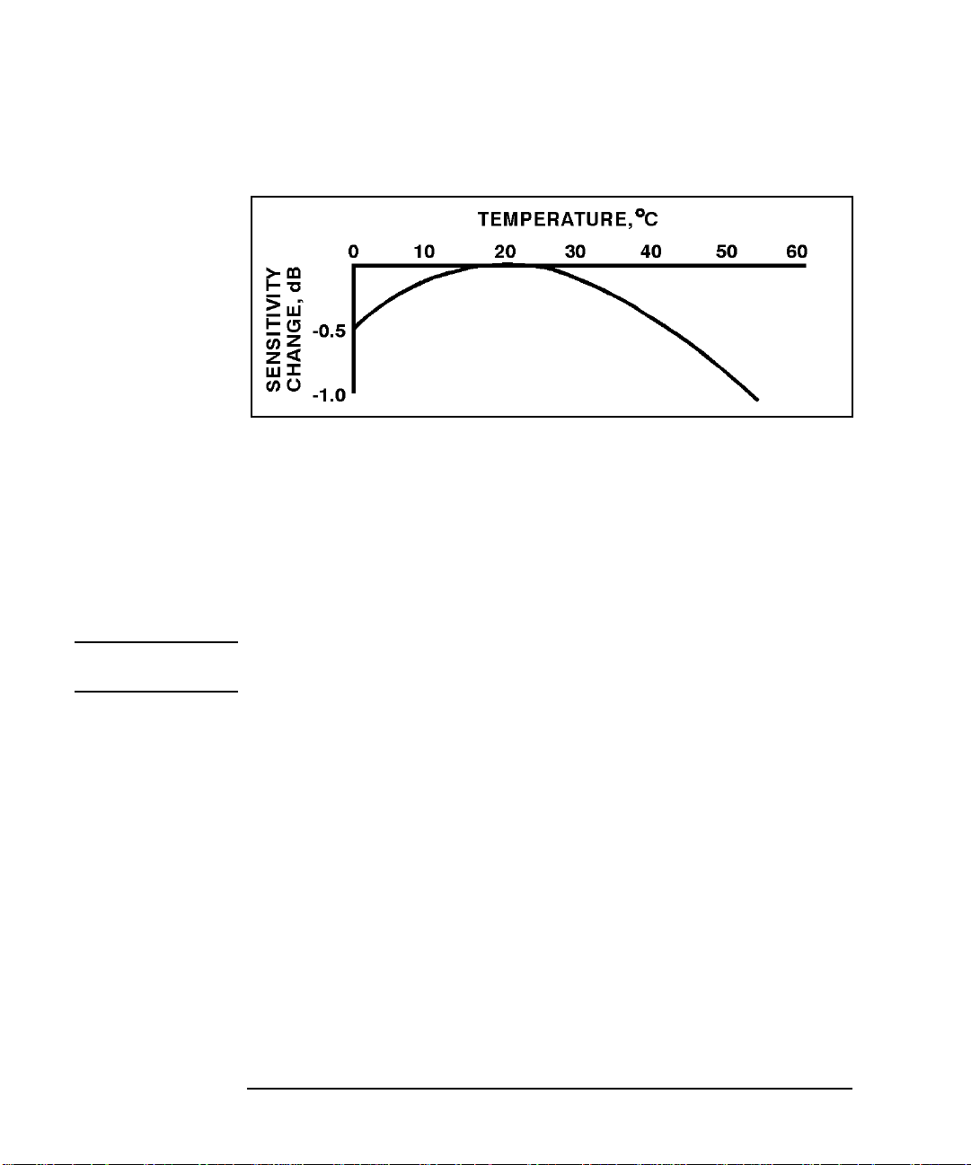
Figure 1-3 Typical Influence of Temperature on Sensitivity
The sensitivity of the power sensor is influenced by ambient
temperature. The sensor should be calibrated at the temperature of
operation to obtain the most accurate results. Typical temperature
sensitivity variations are shown in Figure 1-3.
Operating Instructions
To operate the Power Sensor, refer to the operating instructions in of the
power meter operating and service manual.
NOTE If having an open RF connection on your system is a concern, terminate
the sensor Type-N calibration port with a 50Ω load.
Modulation Effects
When measuring microwave sources that are modulated at the chopper
frequency (nominally 220 Hz for the HP 43X family and 217 Hz for the
HP E4418A/B and HP E4419A/B), or at the first or second harmonic or
submultiples of the chopper frequency, beat notes will occur. Unless the
modulation rate is exactly the chopper frequency, they can usually be
eliminated by averaging since the amplitudes are centered on the actual
power. These frequencies may also be avoided by changing the
modulation frequency slightly, if possible.
If you are using an HP 437B, HP E4418A/B or HP E4419A/B Power
Meter, a filter setting of 128 will minimize most beat note interference.
To minimize beat note interference using a HP 438A Power Meter select
a filter number of at least 7.
14 Chapter 1

HP V8486A Power Sensor
User’s Guide
Linearity Correction
For most HP 8480 series power sensors the correct (A type or D type)
linearity correction table is automatically selected. However, when you
use the HP V8486A power sensor with HP EPM power meters, you must
override the automatic selection and select the D-type correction. This
procedure provides optimum accuracy when making power
measurements >+10dBm. Subsequent connection of another
A-type sensor will result in a warning message stating the “Linearity
Override May be Required”.
To select the linearity type to be applied:
HP E4418B
Press [System Inputs], Tables, Linearity ATyp DTyp.
HP E4419B
Press [System Inputs], Tables, A Linearity ATyp DTyp or B Linearity
ATyp DTyp.
NOTE For use with the HP E4418A and HP E4419A power meters, a firmware
upgrade will be required. Refer to your HP E4418A and HP E4419A
power meter’s user’s guide for instructions on how to obtain the revision
of the firmware currently installed in the unit. The firmware revision
required is A1.03.00 (or above) for the HP E4418A and A2.03.00 (or
above) for the HP E4419A. Contact your local HP Sales and Service
Office for further information.
Chapter 1 15

HP V8486A Power Sensor
User’s Guide
Performance Tests
This section does not establish SWR test procedures since there are
several test methods and different equipment available for testing the
SWR or reflection coefficient. Therefore, the actual accuracy of the test
equipment, all source match corrections, and all harmonics must be
accounted for when measuring against instrument specifications to
determine a pass or fail condition.
To measure the SWR across the waveguide band, use a directional
coupler and detector selected for the band of interest. The directional
coupler should have a directivity greater than 36 dB, such as the HP
V752C/D. The detector should have greater than 0.4 mV/µW sensitivity
and should be calibrated with a rotary vane attenuator with an accuracy
of 2%. Incident power should be less than +20 dBm. A convenient source
is a frequency multiplier driven by an HP 8360 B-Series swept signal
generator.
To check the calibration factor, the Power Sensor should be compared
with another recently calibrated power sensor. The source should be
leveled with a reference coupler that has low SWR and high directivity to
monitor or level the incident power.
For calibration factor and error analysis we suggest HP Application
Note 64-1A: HP literature number 5965-6630E, "Fundamentals of RF
and Microwave Power Measurements".
16 Chapter 1

Replaceable Parts
The part numbers of the hex ball driver and the hardware are listed in
Figure 1. In addition, the following protective parts are replaceable:
Table 1-4 Replaceable Parts
Part Number Description Usage
1401-0214 protective cap Type-N connector
08486-40103 protective cover V-band waveguide flange
There are no other replaceable parts for this product.
A listing of Hewlett-Packard sales and service offices is located at the
end of this manual.
Repair and Adjustments
HP V8486A Power Sensor
User’s Guide
Do not attempt to repair or adjust the Power Sensor. Due to the extreme
static sensitivity of the Power Sensor, customer repair is not
recommended. If your Power Sensor should fail or need calibration,
return it to Hewlett-Packard.
CAUTION Do not disassemble the Power Sensor. The Power Sensor is extremely
static sensitive and can be easily damaged. If the Power Sensor shows
evidence of attempted customer repair, the warranty may be voided.
Chapter 1 17

HP V8486A Power Sensor
User’s Guide
Table 1-5 Hewlett-Packard Sales and Service Offices
UNITED STATES
Instrument Support Center
Hewlett-Packard Company
(800) 403-0801
EUROPEAN FIELD OPERATIONS
Headquarters
Hewlett-Packard S.A.
150, Route du Nant-d’Avril
1217 Meyrin 2/ Geneva
Switzerland
(41 22) 780.8111
Great Britain
Hewlett-Packard Ltd.
Eskdale Road, Winnersh
Triangle Wokingham,
Berkshire RG41 5DZ England
(44 734) 696622
INTERCON FIELD OPERATIONS
Headquarters
Hewlett-Packard Company
3495 Deer Creek Rd.
Palo Alto, CA 94304-1316
USA
(415) 857-5027
Japan
Hewlett-Packard Japan, Ltd.
9-1 Takakura-Cho, Hachioji
Tokyo 192, Japan
(81 426) 60-2111
China
China Hewlett-Packard Co.
38 Bei San Huan X1 Road
Shuang Yu Shu
Hai Dian District
Beijing, China
(86 1) 256-6888
France
Hewlett-Packard France
1 Avenue Du Canada
Zone D’Activite De Courtaboeuf
F-91947 Les Ulis Cedex
France
(33 1) 69 82 60 60
Australia
Hewlett-Packard Australia Ltd.
31-41 Joseph Street
Blackburn, Victoria 3130
(61 3) 895-2895
Singapore
Hewlett-Packard Singapore
(Pte.) Ltd.
150 Beach Road
#29-00 Gateway West
Singapore 0718
(65) 291-9088
Germany
Hewlett-Packard GmbH
Hewlett-Packard Strasse
61352 Bad Homburg v.d.H
Germany
(49 6172) 16-0
Canada
Hewlett-Packard (Canada) Ltd.
17500 South Service Road
Trans-Canada Highway
Kirkland, Quebec H9J 2X8
Canada
(514) 697-4232
Taiwan
Hewlett-Packard Taiwan
8th Floor, H-P Building
337 Fu Hsing North Road
Taipei, Taiwan
(886 2) 712-0404
18 Chapter 1

HP V8486A Power Sensor
User’s Guide
Warranty
This Hewlett-Packard instrument product is warranted against defects
in material and workmanship for a period of 1 year from date of
shipment. During the warranty period, Hewlett-Packard Company will,
at its option, either repair or replace products which prove to be
defective.
For w arranty service or repair, this product must be returned to a service
facility designated by Hewlett-Packard. Buyer shall prepay shipping
charges to Hewlett-Packard and Hewlett-Packard shall pay shipping
charges to return the product to Buyer. However, Buyer shall pay all
shipping charges, duties, and taxes for products returned to
Hewlett-Packard from another country.
Hewlett-Packard warrants that its software and firmware designated by
Hewlett-Packard for use with an instrument will execute its
programming instructions when properly installed on that instrument.
Hewlett-Packard does not warrant that the operation of the instrument,
or software, or firmware will be uninterrupted or error-free.
Limitation of Warranty
The foregoing warranty shall not apply to defects resulting from
improper or inadequate maintenance by Buyer, Buyer-supplied softw are
or interfacing, unauthorized modification or misuse, operation outside of
the environmental specifications for the product, or improper site
preparation or maintenance.
NO OTHER WARRANTY IS EXPRESSED OR IMPLIED. HEWLETTPACKARD SPECIFICALLY DISCLAIMS THE IMPLIED
WARRANTIES OF MERCHANTABILITY AND FITNESS FOR A
PARTICULAR PURPOSE.
Exclusive Remedies
THE REMEDIES PROVIDED HEREIN ARE BUYER’S SOLE AND
EXCLUSIVE REMEDIES. HEWLETT-PACKARD SHALL NOT BE
LIABLE FOR ANY DIRECT, INDIRECT, SPECIAL, INCIDENTAL, OR
CONSEQUENTIAL DAMAGES, WHETHER BASED ON CONTRACT,
TORT, OR ANY OTHER LEGAL THEORY.
Chapter 1 19

Index
A
adjustments
C
cal factor
calibration factor
calibration factor uncertainty
calibrations
power meter
CF
, 6
connections
connectors
D
dimensions
F
frequency range
I
interface
V-band
L
linearity correction
M
marker
maximum power
measurements
power
modulation effects
N
net weight
nominal impedance
, 17
, 13
, 6
, 12
, 8
, 5
, 5
, 5
, 11
, 15
, 4
, 5
, 12
, 14
, 5
, 5
O
operating
environment
precautions
temperature range
operating environment
operating precautions
, 6
operating temperature range
P
packaging
performance tests
power
maximum
worst case linearity
power measurements
power meter calibrations
power range
R
repair
, 17
replaceable parts
Rho
, 5
S
specifications
standing wave ratio
storage
T
temperature
operating range
tests
performance
U
uncertainty
calibration factor
, 10
, 10
, 9
, 5
, 5
, 5
, 9
, 16
, 16
, 17
, 5
, 6
, 5
, 5
, 5
, 12
, 10
, 10
, 12
V
V-band interface
W
warranty
worst case power linearity
, 3, 19
, 5
, 11
, 5
1 Index
 Loading...