

Page 1

Agilent
V3500A Handheld RF Power Meter
Data Sheet
The first palm-sized power meter from Agilent
Technologies that delivers high lab quality
RF power measurements for installation and
maintenance or R&D lab environments
Page 2

Why Agilent’s Power Meters and Sensors?
Reliable, high-performing solutions
Every power meter and sensor from Agilent consistently delivers great results.
A sure investment for many years to come
Code-compatibility between power meters reduces the need for re-coding. Not
only that, all Agilent power meters are backward-compatible with most legacy
power sensors.
One specific application: One right solution
Agilent offers a wide selection of power meters and sensors for practically
all application needs—wireless communications, radar pulse measurements,
component test and more.
Global network support
No matter where you are, Agilent is committed to giving you the 24-hour support you need regarding our products, applications or services.
Agilent’s power meters have long been
recognized as the industry standard for
RF and microwave power measurements.
2
Page 3

Compact, Portable Solutions for Today’s RF Power Measurements
For production testing For R&D and design verification For installation and
maintenance
• Integrated power sensor eliminates
the need to carry separate sensor
• Lightweight and rugged
• Truly portable (with AA batteries)
• Wide dynamic and frequency range
• Quick and easy testing with built-in
backlight display
• Compact build saves rack space
• Compact build saves bench space
• Simple set-up and usage
• Wide dynamic and frequency range
• Simple set-up and usage
• Wide dynamic and frequency range
• High accuracy
• Advanced troubleshooting of
designs with built-in backlight
display for easy readings and data
recording
Associated with mobile phones and infrastructure, wireless
sensors and transceivers, and WiMAX™, WLAN, RFID, mobile
®
radio, Zigbee, and Bluetooth
devices
3
Page 4

Introducing the New Member of the Power Meter Family –
the Agilent V3500A
Key features
• Broad 10MHz to 6GHz
frequency range enables use
in variety of applications,
including test of mobile
phones and infrastructures,
WLAN devices, RFID readers,
and WiMAX devices
• Large dynamic range of
–63dBm to +20dBm
measures various types of
signals, either directly from the
device-under-test or through
layers of cabling and fixtures
• Integrated power sensor
eliminates the need to carry a
separate sensor and makes it
the most compact and portable
RF power measurement
instrument
• Internal power reference
enables self-calibration and
excludes the need to perform
independent calibration before
using the instrument
• Compensate for cable losses
with the Relative Offset
function that can add an offset
to the display ranging between
–99.99dB and +99.99dB
• Absolute accuracy up to
±0.21dB enables more precise
characterization of devices,
tighter test limits, and more
accurate fixture calibration
The Agilent V3500A handheld RF
power meter is a compact, portable
instrument that makes lab quality RF
power measurements in both field
and R&D laboratory environments.
With an absolute accuracy up to
±0.21dB, a wide frequency range of
10MHz to 6GHz, and measurement
range of –63dBm to +20dBm, the
V3500A is suitable for a wide variety
of RF measurement applications. Its
built-in power sensor eliminates the
need for users to carry both an instrument and a separate sensor module,
and the same sensor is used when
duplicating tests or measurements
for better repeatability. Truly portable,
the V3500A fits easily into your hand
or a toolkit and optional loop holster
carrying case with shoulder strap
is also available to fit your need. To
optimize flexibility, it’s capable of
drawing operating power from batteries, an AC-DC converter module, or a
computer via the USB interface. With
its features and very attractive price,
the V3500A truly redefines superior
value.
High accuracy in both the lab
and field
Whether it’s used in the field or on
the factory floor, the Agilent V3500A
makes lab quality RF measurements
quickly and easily. Its absolute
accuracy up to ±0.21dB,enables
more precise characterization of
devices, tighter test limits, and more
accurate fixture calibration. In the
laboratory, it can be used as an RF
power data-logger. Using normal or
high speed mode, it easily captures
and transfers data to your personal
computer through its built-in USB
interface (cable supplied), allowing
for trend or drift analysis. Despite its
small package, the V3500A provides
outstanding accuracy on the bench,
replacing much larger and more
expensive instrumentation.
Convenient utilities
The V3500A incorporates several
handy and practical utilities that
make it easier than ever to attain high
quality RF measurements with this
handheld instrument. Compensate
the display reading for any losses or
gains between the location where
the level of power is desired and the
actual point where the power can be
measured. Typically the compensation
will be required for cable loss. The
relative offset factor can be as large
as 99.99dB, and the offset can be
programmed with a resolution of
0.01dB. A number of averaging values can be used when the signal you
want to measure varies significantly
with time. A hold command saves a
measurement that is made in a hard
to reach area until the instrument
can be retrieved. A backlight can be
illuminated when making measurements in poorly lit areas. To maximize
battery life, the V3500A can be set up
to turn off the backlight or the instrument entirely after a specific period of
time. Once the instrument utilities are
setup in the manner you prefer, the
instrument state can be saved for the
next use.
4
Page 5
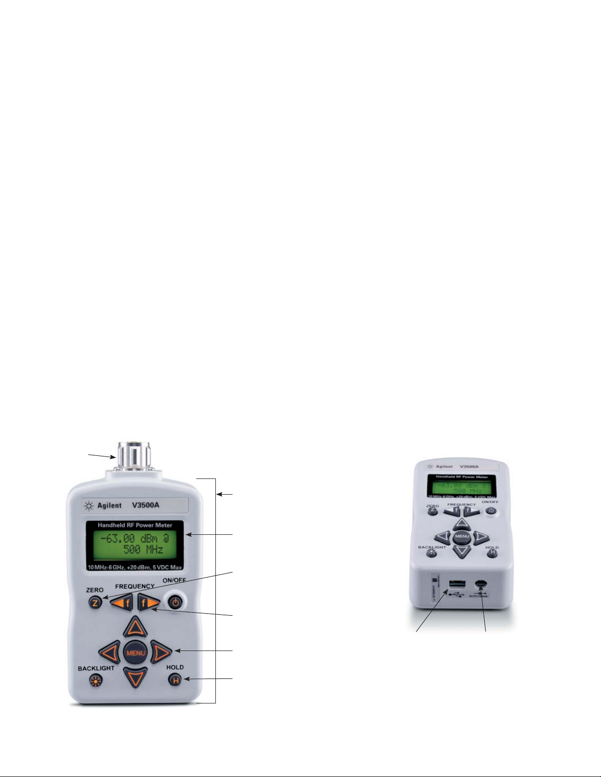
Take a Closer Look
RF connector
In the RF world, cables are often
equipped with N-connectors and
SMA connectors. N-con nectors
are commonly used on test instrumentation, because they are rugged,
can handle high powers, and perform
well up to about 18GHz.
This section contains information
about how to make RF signal
connections to the Type N male
RF connector (50 Ω characteristic
impedance—refer to Figure 1) of the
V3500A for power measurement.
Connection for a power
measurement
NOTE: When connecting the Type N
connector of the V3500A to a Type
N female connector for a power
measurement, observe the following
proper practice for tightening the
connection.
Type N male
connector
nut
While holding the body of the power
meter in one hand, turn the Type N
male connector nut to tighten the
connection (do not turn the body
of the V3500A). Continue to do so
until the connection is hand-tight.
It is important to turn the nut of the
connector rather than the body of
the power meter when tightening the
connection.
USB port
NOTE: The term USB (Universal
Serial Bus) is used in this data sheet.
USB is simply another term for the
Universal Serial Bus.
The power meter has a USB 2.0
interface with a USB type Mini-B port
(refer to Figure 2). The V3500A can be
remotely programmed over this USB
interface. In addition to programming,
the V3500A can be powered by the
USB. With the USB connected and
providing power, and the optional
external power disconnected, the
V3500A will be powered from USB
regardless of whether batteries are
present.
NOTE: The interface is USB 2.0 compatible, but with an interface speed of
12Mbps.
External power connector
The power connector provides a
connection for the optional external
power supply (refer to Figure 2). If the
external power supply is connected,
the V3500A will be powered by the
external supply, regardless of whether
USB power or batteries are present.
CAUTION: Only connect the optional
external power supply (V3500A-PWR)
to this connector. Instrument damage may result if improper power is
applied.
Battery power
The V3500A can also be powered
by two AA batteries. If installed, the
batteries will power the V3500A only
if the external power supply and USB
are not connected.
Figure 1. Signal connection
Body – small and lightweight
build to fit into your hand
Built-in backlight display ensures
visibility in dark locations
“Zeroing” key function allows
a more accurate measurement
at low power levels
Frequency keys for rapid setting
of input signal
Arrow keys for menu selection
and settings
“Hold” key allows saving of
measurement that made in
hard to reach area until the
instrument can be retrieved
5
USB type
Mini-B port
for connection
to PC
Figure 2. USB and power connector
External power
connector (use
with optional
power supply)
Page 6

Specifications
Frequency range 10 MHz to 6 GHz
Power range –63 dBm to +20 dBm
Maximum power +23 dBm, 5 VDC
Power accuracy
Frequency range
10 MHz to 3 GHz
3 GHz to 5 GHz
5 GHz to 6 GHz
Frequency range
10 MHz to 3.75 GHz
3.75 GHz to 6 GHz
Frequency range
10 MHz to 3.75 GHz
3.75 GHz to 6 GHz
Frequency range
10 MHz to 3.75 GHz
3.75 GHz to 6 GHz
(at 23 °C ±5 °C)
+20 dBm to +6 dBm
±0.24 dB (characteristic)
±0.16 dB (characteristic)
±0.22 dB (characteristic)
+6 dBm to –9 dBm
±0.26 dB; ±0.07 dB (typical)
±0.40 dB; ±0.07 dB (typical)
–10 dBm to –29 dBm
±0.26 dB; ±0.05 dB (typical)
±0.37 dB; ±0.05 dB (typical)
–30 dBm to –40 dBm
±0.21 dB; ±0.12 dB (typical)
±0.27 dB; ±0.13 dB (typical)
1
(at 0 °C to 18 °C)
+20 dBm to +6 dBm
2
2
2
±0.24 dB
±0.16 dB
±0.22 dB
+6 dBm to –9 dBm
3
3
±0.26 dB
±0.40 dB
–10 dBm to –29 dBm
3
3
±0.30 dB
±0.43 dB
–30 dBm to –40 dBm
3
3
—
—
Linearity (at 23 °C ±5 °C) ±0.10 dB, –40 dBm to +6 dBm
Noise floor –63 dBm
Speed Normal ~2 readings per second (> approximately – 30 dBm)
~1 readings per second (≤ approximately – 30 dBm)
High-speed ~23 readings per second (> approximately – 30 dBm)
~10 readings per second (≤ approximately – 30 dBm)
4
(at 28 °C to 50 °C)
4
+20 dBm to +6 dBm
±0.24 dB
±0.19 dB
±0.47 dB
+6 dBm to –9 dBm
±0.26 dB
±0.40 dB
–10 dBm to –29 dBm
±0.26 dB
±0.37 dB
–30 dBm to –40 dBm
—
—
1. Customer spec: X = (x,f) + K(=2) · δ(x,f) + ∆
(x,f[18 °–28 °C]) + μ
E
where:
X = mean of the data taken in the frequency range stated (x,f)
δ = standard deviation of the data taken in the frequency range stated (x,f)
x = measured value at test frequencies
f = frequency range over which data was taken for specification
μ = measurement uncertainty
∆
= change associated temperature variation
E
18 °–28 °C = statistics generated separately at these temperatures and larger statistical value used in setting spec.
2. Characteristic (or expected value): characteristic indicates performance that a unit would be expected to exhibit under the following conditions:
• Ambient operating temperature of 18 ° to 23 °C, unless otherwise noted
• After specified warm up time of 30 minutes
• Does not include measurement uncertainty
This performance is not warranted.
3. Typical (mean + 3 standard deviations): typical indicates performance that all units will meet under the following conditions:
• Ambient operating temperature of 23 °C, unless otherwise noted
• After specified warm up time of 30 minutes
• Does not include measurement uncertainty
This performance is not warranted.
4. Typical performance that all instruments will meet under the following conditions:
• Temperature range of 0 to 18 °C or 28 °C to 50 °C as specified
• After specified warm up time of 30 minutes
• Does not include measurement uncertainty
This performance is not warranted.
6
Page 7
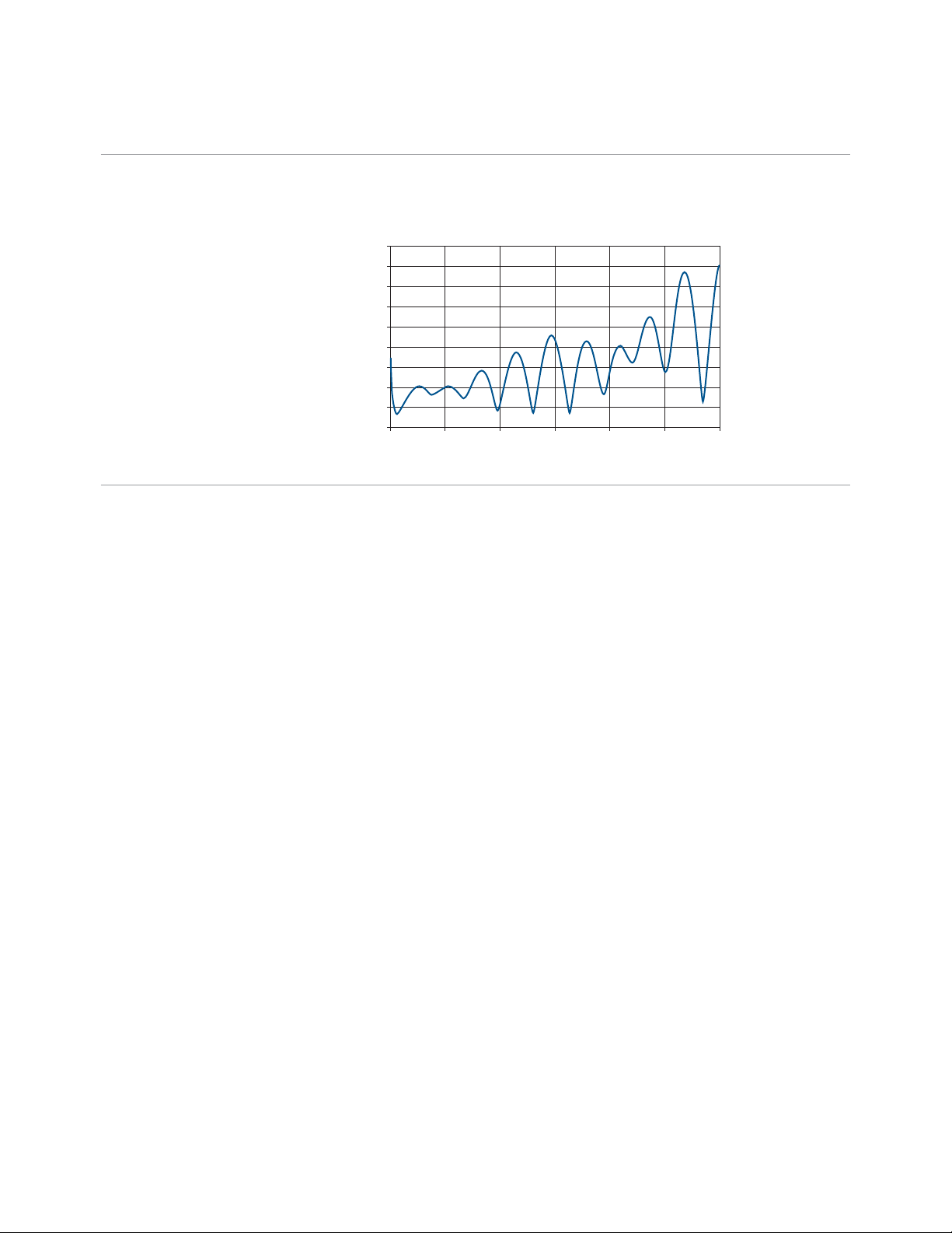
Specifications
SWR 1.12:1, 10 MHz to 3.75 GHz
1.20:1, 3.75 GHz to 6 GH
SWR (typical)
1.18
1.16
1.14
1.12
1.10
1.08
SWR (x:1)
1.06
1.04
1.02
1
0 1000 2000 3000
Frequency (MHz)
1. Typical (mean + 3 standard deviations): typical indicates performance that all units will meet under the following conditions:
• Ambient operating temperature of 23 °C, unless otherwise noted
• After specified warm up time of 30 minutes
• Does not include measurement uncertainty
This performance is not warranted.
1
4000 5000 6000
7
Page 8

Specifications (continued)
Product characteristics
Power (equipped with auto-shutoff) • Two 1.5 V alkaline AA batteries (typical battery life: 17.5 hours1 with low battery indicator
• USB interface cable (Standard-A to Type-B)
• Optional external DC power supply3 (V3500A-PWR)
Display • 4 digits with backlight and auto-shutoff feature
• Hold feature—most recent reading is shown on the display and is no longer updated
Connector • USB 2.0 interface with a mini-B USB connector
• Type N male RF connector (50 Ω characteristic impedance)
Operating environment • At 0 ° to 50 °C
• Up to 80% RH for temperature up to 35 °C, non-condensing
• Altitude up to 2,000 meters
Storage compliance • –10 °C to 70 °C
• Non-operating maximum humidity: 90% at 65 °C, non-condensing
EMC compliance Certified with
• IEC 61326-2-1:2005/EN 61326-2-1:2006
• Canada: ICES-001:2004
• Australia/New Zealand: AS/NZS CISPR11:2004
Pollution degree Pollution Degree 2
Dimensions (W × H × D) 79 mm × 134 mm × 49 mm (without N-connector)
Weight 0.5 kg
Waranty • One year for the V3500A Handheld RF Power Meter
• Three months for the standard shipped and optional accessories
Calibration cycle One year
2
4
1. Typical battery life was measured in the default conditions from the factory at 500 MHz with backlight off and no USB communications. With
backlight on, typical battery life is 2.5 hours.
2. With the USB connected and providing power, and the optional external power disconnected, the V3500A will be powered from USB regardless of
whether batteries are present.
3. If the external power supply is connected, the V3500A will be powered by the external supply, regardless of whether USB power or batteries are
present.
4. The interface is USB 2.0 compliant but with an interface speed of 12 Mbps.
8
Page 9
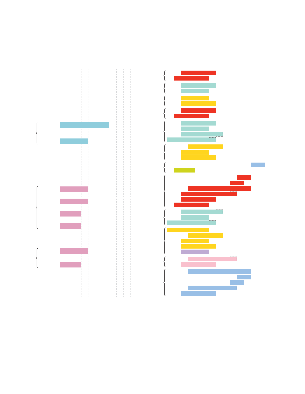
Agilent Power Meter and Power Sensors Selection Guide
Peak-and-average power sensors
(breakdown by dynamic range)
Power
N1922A (30 MHz BW)
N1921A (30 MHz BW)
E9327A (5 MHz BW)
E9326A (1.5 MHz BW)
E9323A (5 MHz BW)
E9322A (1.5 MHz BW)
E9325A (300 kHz BW)
–65 to +20 dBm –60 to +20 dBm –35 to +20 dBm
E9321A (300 kHz BW)
N848XB Series
–5 to +44 dBm
E930XB Series
–30 to +44 dBm
U200XB Series
–30 to +44 dBm
N848XH Series
–15 to +35 dBm
E930XA/H Series
–50 to +30 dBm
U200XH Series
–50 to +30 dBm
848XA Series
–30 to +20 dBm
N848XA Series
–35 to +20 dBm
E930XA Series
–60 to +20 dBm
U200XA Series
–60 to +20 dBm
V3500A
–63 dBm to +20 dBm
E441XA Series
–70 to +20 dBm
848XD Series
–70 to –20 dBm
Average power sensors
(breakdown by dynamic range)
Power
N8481B
N8482B
E9300B
E9301B
U2001B
U2000B
N8481H
N8482H
E9300H
E9301H
E9300A OPT-H25
E9304A OPT-H19
U2002H
U2001H
U2000H
V8486A W8486A
8483A (75 ohm)
N8486AQ
N8486AR
N8487A
N8485A OPT-33
N8481A
N8482A
E9300A OPT-H24
E9301A
E9304A OPT-H18
U2004A
U2002A
U2001A
U2000A
V3500A
E4413A OPT-H33
E4412A
8487D
Q8486D
R8486D
8485D OPT-33
8481D
9 kHz
Frequency
Legend
2 GHz
6 GHz
18 GHz
33 GHz
40 GHz
50 GHz
10 MHz
100 kHz
50 MHz
4.2 GHz
26.5 GHz
75 GHz
■ N192x peak-and-average sensors
Compatible with P-Series power meters
■ E932x peak-and-average sensors
Compatible with EPM-P and P-Series power meters
110 GHz
9 kHz
Frequency
Legend
100 kHz
■ N848X average thermocouple sensor
10 MHz
50 MHz
2 GHz
6 GHz
4.2 GHz
18 GHz
24 GHz
33 GHz
26.5 GHz
40 GHz
50 GHz
75 GHz
110 GHz
■ 848XD average diode sensor
■ 848X thermocouple sensor
■ E441X 1-path diode CW-only sensor
■ E930X 2-path diode true-average sensor
■ U200X USB sensors
■ V3500A Handheld RF Power Meter
9
Page 10

Ordering Information
V3500A handheld RF power meter
Standard shipped accessories
USB interface cable Type A to Mini-B, 2.5 meter (8.2 feet)
User’s guide Printed Agilent V3500A Handheld RF Power Meter, 10 MHz to 6 GHz User’s Guide
CD-ROM Agilent V3500A Product Reference CD-ROM
Accessories, calibration and documentation options
V3500A-PWR External power supply
V3500A-SHL Holster carry case with shoulder strap
V3500A-CA1 USB cable type A to Mini-B, 2.5 meter (8.2 feet)
V3500A-ABA English User’s Guide
V3500A-ABJ Japanese User’s Guide
V3500A-AB2 Simplified Chinese User’s Guide
10
Page 11
www.agilent.com
www.agilent.com/find/V3500A
Agilent Email Updates
www.agilent.com/find/emailupdates
Get the latest information on the
products and applications you select.
www.lxistandard.org
LXI is the LAN-based successor to
GPIB, providing faster, more efficient
connectivity. Agilent is a founding
member of the LXI consortium.
Agilent Channel Partners
www. agilent.com/find/channelpartners
Get the best of both worlds: Agilent’s
measurement expertise and product
breadth, combined with channel
partner convenience.
Bluetooth and the Bluetooth logos are trademarks owned by Bluetooth SIG, Inc., U.S.A.
and licensed to Agilent Technologies, Inc.
WiMAX is a trademark of the WiMAX Forum.
Remove all doubt
Our repair and calibration services
will get your equipment back to
you, performing like new, when
promised. You will get full value out
of your Agilent equipment throughout its lifetime. Your equipment
will be serviced by Agilent-trained
technicians using the latest factory
calibration procedures, automated
repair diagnostics and genuine parts. You
will always have the utmost confidence
in your measurements. For information
regarding self maintenance of this
product, please contact your Agilent
office.
Agilent offers a wide range of additional
expert test and measurement services
for your equipment, including initial
start-up assistance, onsite education
and training, as well as design, system
integration, and project management.
For more information on repair and
calibration services, go to:
www.agilent.com/find/removealldoubt
For more information on Agilent
Technologies’ products, applications or
services, please contact your local Agilent
office. The complete list is available at:
www.agilent.com/find/contactus
Americas
Canada (877) 894 4414
Latin America 305 269 7500
United States (800) 829 4444
Asia Pacific
Australia 1 800 629 485
China 800 810 0189
Hong Kong 800 938 693
India 1 800 112 929
Japan 0120 (421) 345
Korea 080 769 0800
Malaysia 1 800 888 848
Singapore 1 800 375 8100
Taiwan 0800 047 866
Thailand 1 800 226 008
Europe & Middle East
Austria 43 (0) 1 360 277 1571
Belgium 32 (0) 2 404 93 40
Denmark 45 70 13 15 15
Finland 358 (0) 10 855 2100
France 0825 010 700*
*0.125 €/minute
Germany 49 (0) 7031 464 6333
Ireland 1890 924 204
Israel 972-3-9288-504/544
Italy 39 02 92 60 8484
Netherlands 31 (0) 20 547 2111
Spain 34 (91) 631 3300
Sweden 0200-88 22 55
Switzerland 0800 80 53 53
United Kingdom 44 (0) 118 9276201
Other European Countries:
www.agilent.com/find/contactus
Revised: October 1, 2009
Product specifications and descriptions in
this document subject to change without
notice.
© Agilent Technologies, Inc. 2010
Printed in USA, April 21, 2010
5990-5483EN
 Loading...