

Page 1

Agilent U3401A
4 1/2 Digit Dual Display
Multimeter
Quick Start Guide
Agilent Technologies
Page 2

Notices
© Agilent Technologies, Inc. 2009
No p art o f this manu al may be re produce d in
any form or by any means (including electronic storage and retrieval or translation
into a foreign language) without prior agreement and written consent from Agilent
Technologies, Inc. as governed by United
States and international copyright laws.
Manual Part Number
U3401-90019
Edition
First Edition, March 18, 2009
Printed in Malaysia
Agilent Technologies, Inc.
3501 Stevens Creek Blvd.
Santa Clara, CA 95051 USA
Warranty
The material contained in this document is provided “as is,” and is subject to being changed, without notice,
in future editions. Further, to the maximum extent permitted by applicable
law, Agilent disclaims all warranties,
either express or implied, with regard
to this manual and any information
contained herein, including but not
limited to the implied warranties of
merchantability and fitness for a particular purpose. Agilent shall not be
liable for errors or for incidental or
consequential damages in connection with the furnishing, use, or performance of this document or of any
information contained herein. Should
Agilent and the user have a separate
written agreement with warranty
terms covering the material in this
document that conflict with these
terms, the warranty terms in the separate agreement shall control.
Technology Licenses
The hardware and/or software described in
this document are furnished under a license
and may be used or copied only in accordance with the terms of such license.
Restricted Rights Legend
U.S. Government Restricted Rights. Software and technical data rights granted to
the federal government include only those
rights customarily provided to end user customers. Agilent provides this customary
commercial license in Software and technical data pursuant to FAR 12.211 (Technical
Data) and 12.212 (Computer Software) and,
for the Department of Defense, DFARS
252.227-7015 (Technical Data - Commercial
Items) and DFARS 227.7202-3 (Rights in
Commercial Computer Software or Computer Software Documentation).
Safety Notices
CAUTION
A CAUTION notice denotes a hazard. It calls attention to an operating procedure, practice, or the like
that, if not correctly performed or
adhered to, could result in damage
to the product or loss of important
data. Do not proceed beyond a
CAUTION notice until the indicated
conditions are fully understood and
met.
WARNING
A WARNING notice denotes a
hazard. It calls attention to an
operating procedure, practice, or
the like that, if not correctly performed or adhered to, could result
in personal injury or death. Do not
proceed beyond a WARNING
notice until the indicated conditions are fully understood and
met.
ii U3401A Quick Start Guide
Page 3

Contents
The Front Panel at a Glance 1
The Display at a Glance 2
Getting Started 4
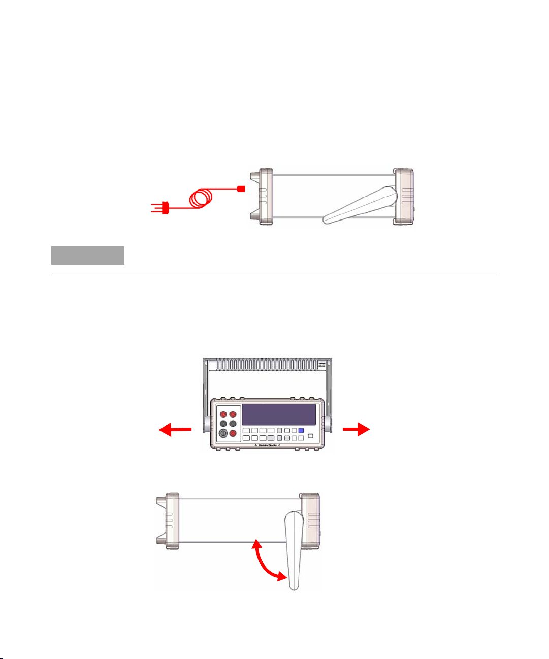
1 Connect the power cord 4
2 Adjust the carrying handle 4
3 Connect the test leads to the input terminals 5
4 Turn on the multimeter 5
5 Select a function 6
6 Set the range 6
7 Using the secondary display 6
8 Math operation 7
9 For more information 8
iii U3401A Quick Start Guide
Page 4

iv U3401A Quick Start Guide
Page 5
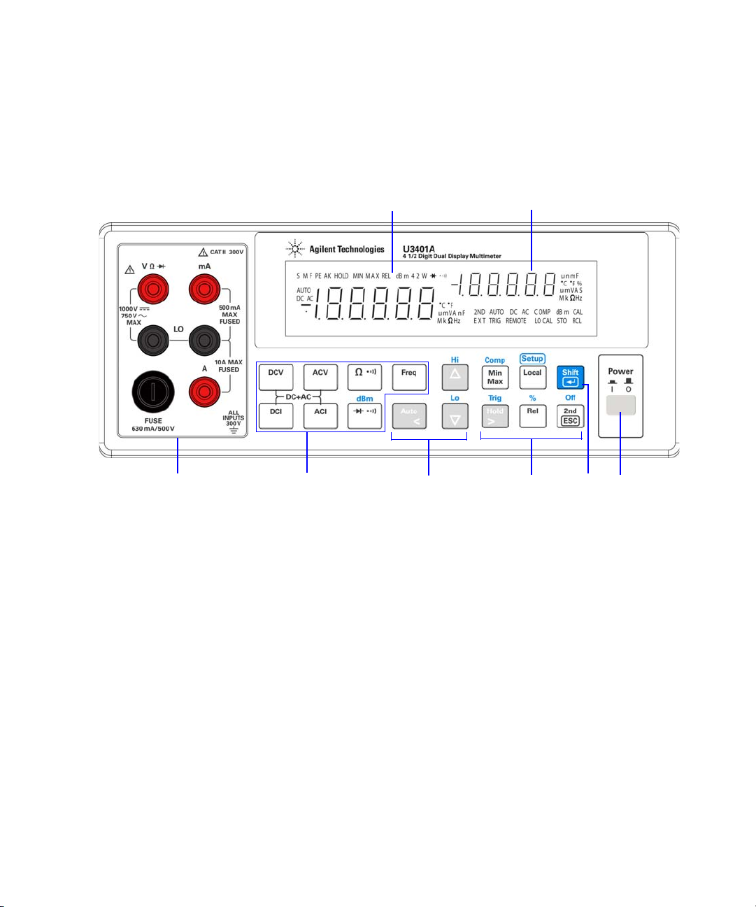
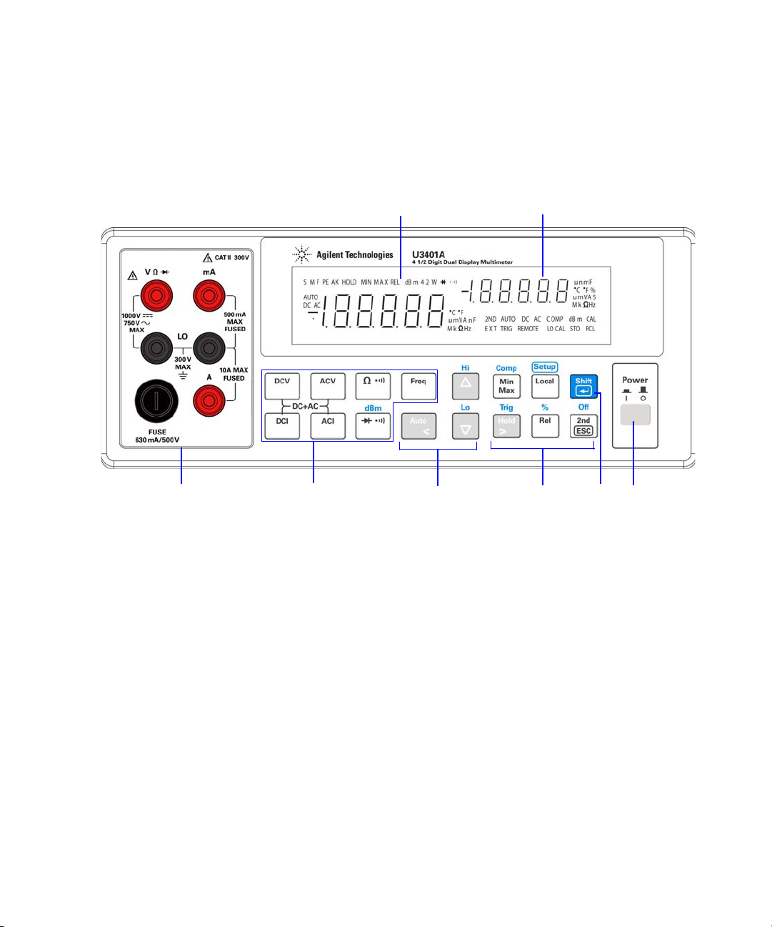
The Front Panel at a Glance
Measurement
function
keypads
Secondary display
Input terminals
and current fuse
Autoranging,
manual range,
and comparator
operation
Power
on/off
switch
Math
operation
keypads
Shift
Primary display
Getting Started 1
U3401A Quick Start Guide 1
Page 6
1Getting Started
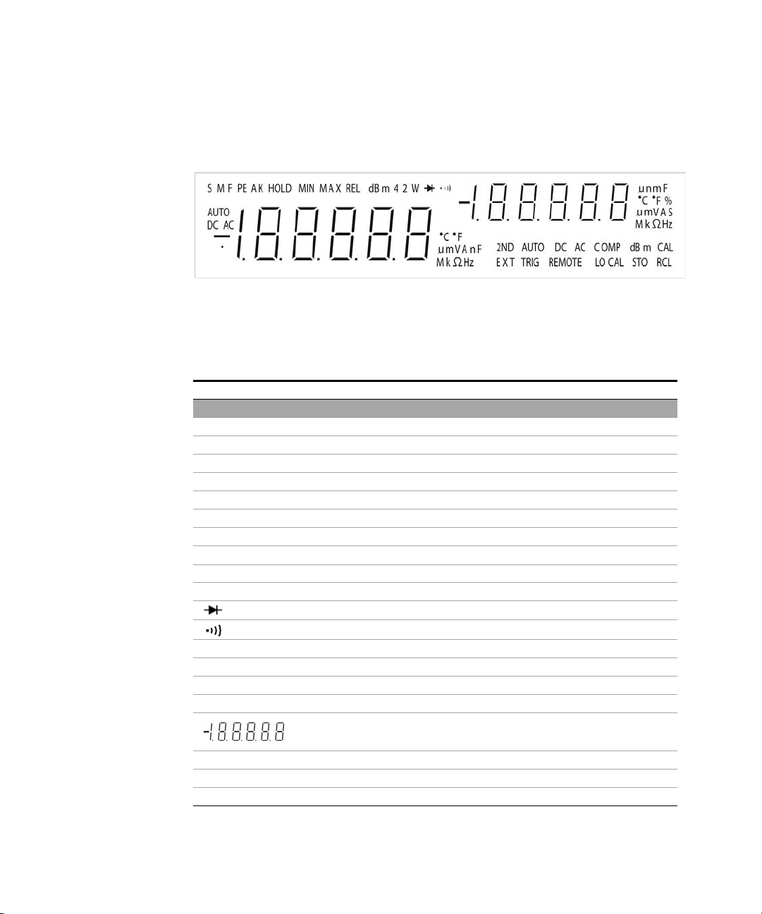
The Display at a Glance
Figure 1-1 VFD full display with all segments illuminated
The highly visible vacuum fluorescent display (VFD) annunciators are
described in the following table:
Annunciator Description
Primary display
S Reading rate: Slow. Not applicable for the U3401A.
M Reading rate: Medium. Not applicable for the U3401A.
F Reading rate: Fast. Not applicable for the U3401A.
PEAK Peak measurement. Not applicable for the U3401A.
HOLD Data hold
MIN MinMax math operation: Minimum value shown on the primary display
MAX MinMax math operation: Maximum value shown on the primary display
REL Relative value
dBm Decibel unit relative to 1 mW
4 2 W 4-wire/2-wire resistance. Not applicable for the U3401A.
Diode test
Audible continuity test for resistance
AUTO Autoranging
DC Direct current
AC Alternating current
DCAC AC + DC
Polarity, digits, and decimal points for primary display
°C Celcius temperature unit. Not applicable for the U3401A.
°F Fahrenheit temperature unit. Not applicable for the U3401A.
mV Voltage unit: mV, V
2 U3401A Quick Start Guide
Page 7
Getting Started 1
Annunciator Description
μmA Current unit: μA, mA, A
μmnF Capacitance unit: μF, nF, mF
MkΩ Resistance unit: Ω, kΩ, MΩ
MkHz Frequency unit: Hz, kHz, MHz
Secondary display
Polarity, digits, and decimal points for primary display
μmnF Capacitance unit: μF, nF, mF
°C Celcius temperature unit. Not applicable for the U3401A.
°F Fahrenheit temperature unit. Not applicable for the U3401A.
% Duty cycle measurement
mV Voltage unit: mV, V
μmA Current unit: μA, mA, A
SShift mode
MkΩ Resistance unit: Ω, kΩ, MΩ
2ND Secondary display is enabled. Not applicable for the U3401A.
AUTO Autoranging
DC Direct current
AC Alternating current
DCAC AC + DC
COMP Compare operation
dBm Decibel unit relative to 1 mW
CAL Calibration mode
EXT External. Not applicable for the U3401A.
TRIG Trigger mode
REMOTE Remote interface control. For calibration use only.
LOCAL Local mode
STO Store instrument state. Not applicable for the U3401A.
RCL Recall stored instrument state. Not applicable for the U3401A.
U3401A Quick Start Guide 3
Page 8
1Getting Started
NOTE
Getting Started
This section describes the basic step- by- step procedures on how to
operate the multimeter.
1
The line voltage switch and fuse are set at the factory according to the country of
destination.
2 Adjust the carrying handle
Connect the power cord
Grasp the handle by the sides and pull outward as indicated by the red
arrows below.
Then, adjust the handle to the desired position.
4 U3401A Quick Start Guide
Page 9
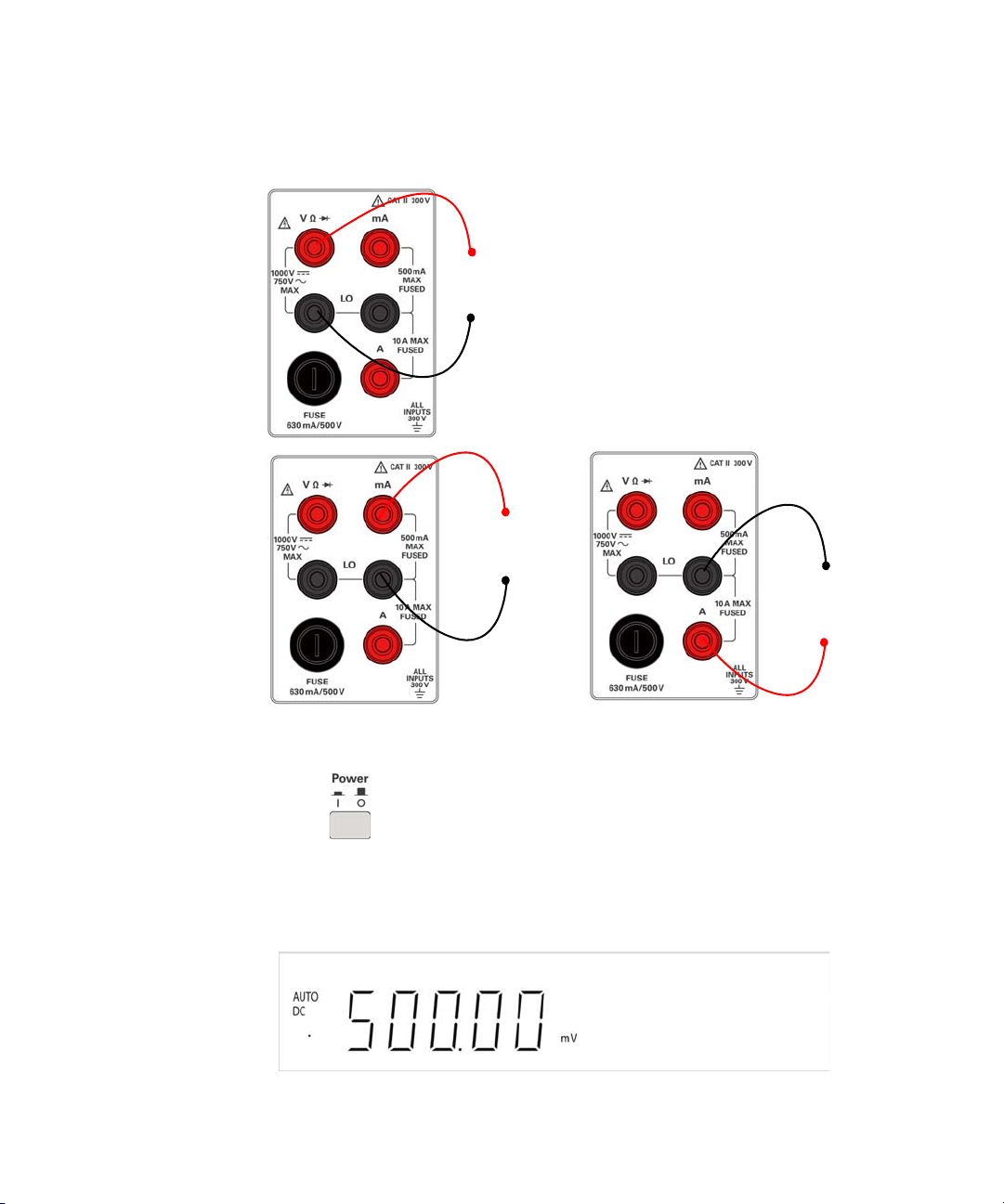
Connect the test leads to the input terminals
+
–
AC or DC voltage, frequency, or resistance measurement and
diode or continuity test.
+
–
AC or DC current
up to 10 A RMS
+
–
AC or DC current
3
Getting Started 1
4 Turn on the multimeter
Push to turn on the multimeter. The front-panel display
illuminates while the multimeter performs its power- on self- test.
The multimeter powers up in the DC voltage function with autoranging
enabled. Typical display :
U3401A Quick Start Guide 5
Page 10
1Getting Started
5
6
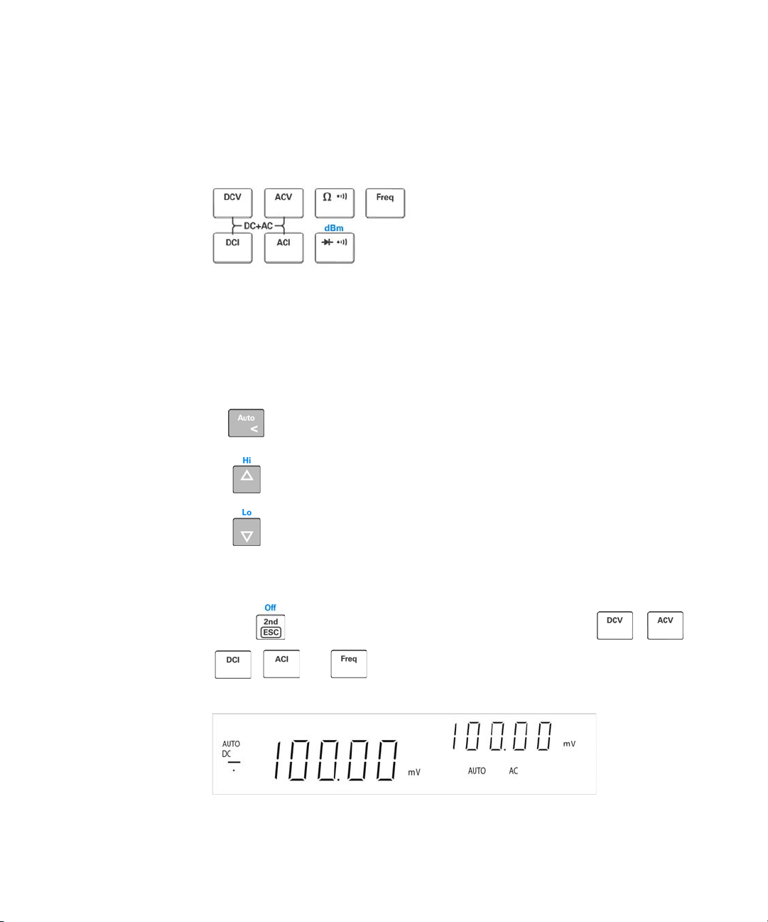
Select a function
Press one of the following keys to select a measurement function.
Set the range
For most measurement functions, you can allow the multimeter to
select the range automatically by using the autoranging function, or you
can select a fixed range using manual ranging. The AUTO annunciator is
displayed when the autoranging function is selected.
Selects autoranging and disables manual ranging. Press
to toggle between the manual ranging and autoranging.
Selects a higher range and disable autoranging.
Selects a lower range and disable autoranging.
Using the secondary display
7
Press followed by a specified function keys such a , ,
, or to enable the secondary display mode.
6 U3401A Quick Start Guide
Page 11
Getting Started 1
NOTE
Press , to disable the secondary display.
The multimeter has an increased key response time (0.6 s to 1 s) when in dual display
mode. You may need to press the selected key until the multimeter responses.
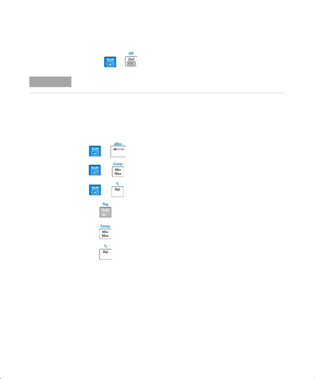
Math operation
8
The U3401A has six math operations — dBm, Rel (relative), MinMax,
Comp (compare), Hold and Percentage (%).
+
+
+
Press to select dBm measurement.
Press to select Comp math operation.
Press to enable Percentage math operation.
Press to enable Hold math operation.
Press to enable the MinMax math operation.
Press to select the Rel math operation.
U3401A Quick Start Guide 7
Page 12

1Getting Started
The following table presents a summary of the math operations that can
be used with each measurement function.
Measurement functions
DCV
DCI
Resistance
ACV
ACI
Frequency
Diode/Continuity
dBm Rel Min Max Comp Hold %
✔✔✔✔✔ ✔ ✔
- ✔✔ ✔✔ ✔ ✔
--✔✔✔ ✔ ✔
✔✔✔✔✔ ✔ ✔
- ✔✔ ✔✔ ✔ ✔
- ✔✔ ✔✔ ✔ ✔
--✔✔✔ ✔ ✔
Allowed math operations
For a detailed operation procedure of each math operation, refer to the
Agilent U3401A User’s and Service Guide.
For more information
9
The Agilent U3401A User’s and Service Guide contains more detailed
information on the front panel, measurement functions, math
operations, and the setup menu (allows you to customize the instrument
settings). It also contains product specifications, rack mounting
instructions, and replaceable parts information.
8 U3401A Quick Start Guide
Page 13

Multimètre double
affichage 4 1/2 chiffres
Agilent U3401A
Guide de mise en route
Agilent Technologies
Page 14

Avertissements
CAUTION
WARNING
© Agilent Technologies, Inc. 2009
Conformément aux lois internationales
relatives à la propriété intellectuelle, toute
reproduction, tout stockage électronique et
toute traduction de ce manuel, totaux ou
partiels, sous quelque forme et par quelque
moyen que ce soit, sont interdits sauf
consentement écrit préalable de la société
Agilent Technologies, Inc.
Référence du manuel
U3401-90019
Edition
Première édition, 18 mars 2009
Imprimé en Malaisie
Agilent Technologies, Inc.
3501 Stevens Creek Blvd.
Santa Clara, CA 95051 Etats-Unis
Garantie
Les informations contenues dans ce
document sont fournies « en l’état » et
pourront faire l’objet de modifications
sans préavis dans les éditions
ultérieures. Dans les limites de la
législation en vigueur, Agilent exclut
en outre toute garantie, expresse ou
implicite, concernant ce manuel et les
informations qu’il contient, y compris,
mais non exclusivement, les garanties
de qualité marchande et d’adéquation
à un usage particulier. Agilent ne
saurait en aucun cas être tenu pour
responsable des erreurs ou des
dommages incidents ou consécutifs,
liés à la fourniture, à l'utilisation ou
àl'exactitude de ce document ou aux
performances de tout produit Agilent
auquel il se rapporte. Si Agilent et
l’utilisateur ont passé un contrat écrit
distinct, stipulant, pour le produit
couvert par ce document, des
conditions de garantie qui entrent en
conflit avec les présentes conditions,
les conditions de garantie du contrat
distinct remplacent les conditions
énoncées dans le présent document.
techniques) et 12.212 (logiciel informatique)
et, pour le ministère de la Défense, selon les
directives DFARS 252.227-7015
(informations techniques – articles
commerciaux) et DFARS 227.7202-3 (droits
s’appliquant aux logiciels informatiques
commerciaux ou à la documentation des
logiciels informatiques commerciaux).
Avertissements de sécurité
La mention
danger pour le matériel. Si la
manœuvre ou la procédure
correspondante n’est pas exécutée
correctement, il peut y avoir un
risque d’endommagement de
l’appareil ou de perte de données
importantes. En présence de la
mention
s’interrompre tant que les conditions
indiquées n’ont pas été parfaitement
comprises et satisfaites.
ATTENTION
ATTENTION
signale un
, il convient de
ii Guide de mise en route du
Licences technologiques
Le matériel et les logiciels décrits dans ce
document sont protégés par un accord de
licence et leur utilisation ou reproduction
est soumise aux termes et conditions de
ladite licence.
Limitation des droits
Limitations des droits du Gouvernement des
Etats-Unis. Les droits s’appliquant aux
logiciels et aux informations techniques
concédées au gouvernement fédéral
incluent seulement les droits concédés
habituellement aux clients utilisateurs.
Agilent concède la licence commerciale
habituelle sur les logiciels et les
informations techniques suivant les
directives FAR 12.211 (informations
La mention AVERTISSEMENT
signale un danger pour la sécurité
de l’opérateur. Si la manœuvre ou la
procédure correspondante n’est
pas exécutée correctement, il peut
y avoir un risque grave, voire mortel
pour les personnes. En présence
d’une mention AVERTISSEMENT, il
convient de s’interrompre tant que
les conditions indiquées n’ont pas
été parfaitement comprises et
satisfaites.
Page 15

Table des matières
La face avant 1
L'écran d'un coup d'œil 2
Mise en route 4
1 Branchez le cordon d'alimentation 4
2 Réglage de la poignée de transport 4
3 Raccordement des cordons de test aux bornes d'entrée 5
4 Mise sous tension du multimètre 5
5 Sélection d'une fonction 6
6 Définition de la plage 6
7 Utilisation de l'affichage secondaire 7
8 Opération mathématique 7
9 Pour de plus amples informations 8
iii Guide de mise en route du
Page 16

iv Guide de mise en route du
Page 17
La face avant
Touches des
fonctions de
mesure
Affichage secondaire
Bornes d'entrée
et fusible
Sélection
automatique
de plage, plage
manuelle et
opération du
comparateur
Touches des
opérations
mathématiques
Décalage
Affichage principal
Mise en route 1
Guide de mise en route du faradmètre U3401A 1
Commutateur
de marche/arrêt
Page 18

1 Mise en route
L'écran d'un coup d'œil
Figure 1-1 Affichage complet VFD avec rétroéclairage de tous les segments
Les avertisseurs très visibles de l'écran à affichage fluorescent à vide
(VFD) sont décrits dans le tableau suivant :
Avertisseur Description
Affichage principal
S Vitesse de lecture : Slow (lente). Sans objet pour le U3401A.
M Vitesse de lecture : Medium (moyenne). Sans objet pour le U3401A.
F Vitesse de lecture : Fast (rapide). Sans objet pour le U3401A.
PEAK Mesure de crête. Sans objet pour le U3401A.
HOLD Gel des données
MIN
MAX
REL Valeur relative
dBm Décibel par rapport à 1 mW
4 2 W Résistance 4 fils/2 fils. Sans objet pour le U3401A.
AUTO Sélection automatique de plage
Courant continu Courant continu
Courant alternatif Courant alternatif
DCAC Courant alternatif + continu
Opération mathématique MinMax : valeur minimum apparaissant sur
l'affichage
Opération mathématique MinMax : valeur maximum apparaissant sur
l'affichage
Test de diodes
Test sonore de continuité relatif à la résistance
Polarité, chiffres et points décimaux de l'affichage principal
⎦C Température en degrés Celsius. Sans objet pour le U3401A.
⎦F Température en degrés Fahrenheit. Sans objet pour le U3401A.
mV Unité de tension : mV, V
2 Guide de mise en route du faradmètre U3401A
Page 19
Mise en route 1
Avertisseur Description
μmA Unité d'intensité : μA, mA, A
μmnF Unité de capacité : μF, nF, mF
MkΩ Unité de résistance : Ω, kΩ, MΩ
MkHz Unité de fréquence : Hz, kHz, MHz
Affichage secondaire
Polarité, chiffres et points décimaux de l'affichage principal
μmnF Unité de capacité : μF, nF, mF
°C Température en degrés Celsius. Sans objet pour le U3401A.
°F Température en degrés Fahrenheit. Sans objet pour le U3401A.
% Mesure de rapport cyclique
mV Unité de tension : mV, V
μmA Unité d'intensité : μA, mA, A
S Mode de décalage
MkΩ Unité de résistance : Ω, kΩ, MΩ
2ND L'affichage secondaire est activé. Sans objet pour le U3401A.
AUTO Sélection automatique de plage
Courant continu Courant continu
Courant alternatif Courant alternatif
DCAC Courant alternatif + continu
COMP Opération de comparaison
dBm Décibel par rapport à 1 mW
CAL Mode d'étalonnage
EXT Externe. Sans objet pour le U3401A.
TRIG Mode de déclenchement
REMOTE Télécommande d'interface. Pour l’étalonnage uniquement.
LOCAL Mode local
STO Mémorisation de l'état de l'instrument. Sans objet pour le U3401A.
RCL
Récupération de l'état de l'instrument mémorisé. Sans objet pour le
U3401A.
Guide de mise en route du faradmètre U3401A 3
Page 20

1 Mise en route
NOTE
Mise en route
Cette section décrit étape par étape les principales procédures permettant
de faire fonctionner le multimètre.
1
Branchez le cordon d'alimentation
Le commutateur et le fusible de tension secteur sont réglés en usine en fonction
des spécifications dictées par le pays de destination de l'appareil.
2 Réglage de la poignée de transport
Saisissez la poignée par les côtés et tirez vers l'extérieur tel qu'indiqué
par les flèches rouges ci- après.
Réglez ensuite la poignée dans la position souhaitée.
4 Guide de mise en route du faradmètre U3401A
Page 21

Raccordement des cordons de test aux bornes d'entrée
+
-
Tension CA ou CC, fréquence ou mesure de résistance et test
de diode ou test de continuité.
+
-
+
-
Intensité CA
ou CC
3
Mise en route 1
Intensité efficace CA
ou CC jusqu'à 10 A
4 Mise sous tension du multimètre
Appuyez sur pour mettre le multimètre sous tension. Le panneau
avant s'allume pendant que le multimètre réalise un auto- test de mise
sous tension.
Au démarrage, le multimètre active la fonction de tension continue
et la sélection automatique de plage. Affichage typique:
Guide de mise en route du faradmètre U3401A 5
Page 22

1 Mise en route
Sélection d'une fonction
5
Appuyez sur une des touches suivantes pour sélectionner une fonction
de mesure.
6
Définition de la plage
Pour la plupart des fonctions de mesure, vous pouvez permettre
au multimètre de sélectionner la plage automatiquement (en utilisant
la fonction de sélection automatique de plage) ou vous pouvez
sélectionner une plage fixe manuellement. L'avertisseur AUTO s'affiche
lorsque la fonction de sélection automatique de plage est sélectionnée.
Sélectionne la sélection automatique de plage et désactive
la sélection manuelle de plage. Appuyez pour passer de
la sélection automatique de plage à la sélection manuelle
de plage.
Sélectionne une plage supérieure et désactive la sélection
automatique de plage.
Sélectionne une plage inférieure et désactive la sélection
automatique de plage.
6 Guide de mise en route du faradmètre U3401A
Page 23

Mise en route 1
NOTE
Utilisation de l'affichage secondaire
7
Appuyez sur puis sur une touche de fonction spécifique telle que
, , , ou pour activer le mode d'affichage
secondaire.
Appuyez sur , pour désactiver l'affichage secondaire.
Le temps de réponse des touches du multimètre est supérieur (0,6 s à 1 s) en mode double
affichage. Vous devez parfois appuyer sur la touche sélectionnée jusqu'à ce que le
multimètre réponde.
8
Opération mathématique
Le U3401A a six opérations mathématiques — dBm, Rel (valeur
relative), MinMax, Comp (comparaison), Hold et Percentage (%).
+
+
+
Guide de mise en route du faradmètre U3401A 7
Appuyez pour sélectionner la mesure de dBm.
Appuyez pour sélectionner l'opération
mathématique Comp.
Appuyez pour activer l'opération mathématique
Percentage.
Appuyez pour activer l'opération mathématique
Hold.
Page 24

1 Mise en route
Appuyez pour activer l'opération mathématique
MinMax.
Appuyez pour sélectionner l'opération
mathématique Rel.
Le tableau suivant présente un récapitulatif des opérations
mathématiques pouvant être utilisées avec chaque fonction de mesure.
Fonctions de mesure
V CC
I CC
Résistance
V CA
I CA
Fréquence
Diode/Continuité
dBm Rel Min Max Comp Hold %
✔✔✔✔✔ ✔ ✔
- ✔✔ ✔✔ ✔ ✔
--✔✔✔ ✔ ✔
✔✔✔✔✔ ✔ ✔
- ✔✔ ✔✔ ✔ ✔
- ✔✔ ✔✔ ✔ ✔
--✔✔✔ ✔ ✔
Opérations mathématiques autorisées
Pour connaître la procédure de fonctionnement détaillée de chaque
opération mathématique, consultez le document Agilent U3401A User’s
and Service Guide.
Pour de plus amples informations
9
Le document Agilent U3401A User’s and Service Guide contient
des informations plus détaillées sur le panneau avant, les fonctions
de mesure, les opérations mathématiques et le menu de configuration
(ce dernier vous permet de personnaliser les paramètres de
l'instrument). Il comprend également les spécifications du produit,
les instructions de montage en baie et les pièces remplaçables.
8 Guide de mise en route du faradmètre U3401A
Page 25

Agilent U3401A
4 ½ Digit Sekundäranzeige-Multimeter
Schnellstarthandbuch
Agilent Technologies
Page 26

Hinweise
VORSICHT
WARNUNG
© Agilent Technologies, Inc. 2009
Vervielfältigung, Anpassung oder Übersetz-
ung ist gemäß den Bestimmungen des
Urheberrechtsgesetzes ohne vorherige
schriftliche Genehmigung durch die Firma
Agilent Technologies verboten.
Handbuchteilenummer
U3401-90019
Ausgabe
Erste Ausgabe, 18. März 2009
Gedruckt in Malaysia
Agilent Technologies, Inc.
3501 Stevens Creek Blvd.
Santa Clara, CA 95051 USA
Garantie
Das in diesem Dokument enthaltene
Material wird im vorliegenden
Zustand zur Verfügung gestellt und
kann in zukünftigen Ausgaben ohne
vorherige Ankündigung geändert
werden. Agilent Technologies übernimmt keinerlei Gewährleistung für die
in dieser Dokumentation enthaltenen
Informationen, insbesondere nicht für
deren Eignung oder Tauglichkeit für
einen bestimmten Zweck. Agilent
Technologies übernimmt keine Haftung für Fehler, die in diesem Dokument enthalten sind, und für zufällige
Schäden oder Folgeschäden im
Zusammenhang mit der Lieferung,
Ingebrauchnahme oder Benutzung
dieser Dokumentation. Falls zwischen
Agilent und dem Benutzer eine
schriftliche Vereinbarung mit abweichenden Gewährleistungsbedingungen hinsichtlich der in diesem
Dokument enthaltenen Informationen
existiert, so gelten diese schriftlich
vereinbarten Bedingungen.
Technologielizenzen
Die in diesem Dokument beschriebene
Hardware und/oder Software wird unter
einer Lizenz geliefert und darf nur entsprechend den Lizenzbedingungen genutzt oder
kopiert werden.
Nutzungsbeschränkungen
U.S. Government Restricted Rights (eingeschränkte Rechte für die US-Regierung).
Die der Bundesregierung gewährten Rechte
bezüglich Software und technischer Daten
gehen nicht über diese Rechte hinaus, die
üblicherweise Endbenutzern gewährt werden. Agilent stellt diese handelsübliche
kommerzielle Lizenz für Software und
technische Daten gemäß FAR 12.211
(technische Daten) und 12.212 (ComputerSoftware) – für das US-Verteidigungsminis-
terium – gemäß DFARS 252.227-7015 (technische Daten – kommerzielle Produkte) und
DFARS 227.7202-3 (Rechte an kommerzieller Computer-Software oder Computer-Software-Dokumentation) bereit.
Sicherheitshinweise
Ein Hinweis mit der Überschrift
VORSICHT weist auf eine Gefahr
hin. Er macht auf einen Betriebsablauf oder ein Verfahren aufmerksam, der bzw. das bei
unsachgemäßer Durchführung zur
Beschädigung des Produkts oder
zum Verlust wichtiger Daten führen
kann. Setzen Sie den Vorgang nach
dem Hinweis VORSICHT nicht fort,
wenn Sie die darin aufgeführten
Hinweise nicht vollständig verstanden haben und einhalten können.
Eine WARNUNG weist auf eine
Gefahr hin. Sie macht auf einen
Betriebsablauf oder ein Verfahren
aufmerksam, der bzw. das bei
unsachgemäßer Durchführung zu
Verletzungen oder zum Tod führen
kann. Setzen Sie den Vorgang nach
einem Hinweise mit der Überschrift WARNUNG nicht fort, wenn
Sie die darin aufgeführten Hinweise nicht vollständig verstanden
haben und einhalten können.
ii U3401A Schnellstarthandbuch
Page 27

Inhalt
Das vordere Bedienfeld auf einen Blick 1
Die Anzeige auf einem Blick 2
Erste Schritte 4
1 Anschließen des Netzkabels 4
2 Anpassen des Tragegriffs 4
3 Anschließen der Testleitungen an die Eingangsanschlüsse 5
4 Einschalten des Multimeters 5
5 Auswählen einer Funktion 6
6 Einstellen des Bereichs 6
7 Verwenden der Sekundäranzeige 6
8 Math. Operation 7
9 Weitere Informationen 8
U3401A Schnellstarthandbuch iii
Page 28

iv U3401A Schnellstarthandbuch
Page 29

Das vordere Bedienfeld auf einen Blick
Tastenfelder für
Messfunktionen
Sekundäranzeige
Eingangsanschlüsse
und Stromsicherung
Automatische
Bereichswahl,
manuelle
Bereichswahl
und Vergleichsoperation
Ein-/Ausschalter
Tastenfelder für
math. Operationen
Umschalten
Primäranzeige
Erste Schritte 1
U3401A Schnellstarthandbuch 1
Page 30

1Erste Schritte
Die Anzeige auf einem Blick
Abbildung 1-1VFD-Vollanzeige, wobei alle Segmente beleuchtet sind
Die sehr gut sichtbaren Elemente der Vakuumfluoreszenzanzeige (VFD)
werden in der folgenden Tabelle beschrieben:
Melder Beschreibung
Primäranzeige
S Leserate: Langsam. Gilt nicht für U3401A.
M Leserate: Mittel. Gilt nicht für U3401A.
F Leserate: Schnell. Gilt nicht für U3401A.
PEAK Spitzenmessung Gilt nicht für U3401A.
HOLD Datenhalten
MIN
MAX
REL Relativer Wert
dBm Dezibeleinheit relativ zu 1 mW
4 2 W 4-Draht-/2-Drahtwiderstand Gilt nicht für U3401A.
AUTO Automatische Bereichsauswahl
DC Gleichstrom
AC Wechselstrom
DCAC AC+DC
Math. MinMax-Operation: Auf primärer Anzeige angezeigter minimaler
Wert
Math. MinMax-Operation: Auf primärer Anzeige angezeigter maximaler
Wert
Diodentest
Akustischer Widerstands-Durchgangstest
Polarität, Ziffern und Dezimalpunkte für Primäranzeige
⎦C Temperatur in Celsius. Gilt nicht für U3401A.
⎦F Temperatur in Fahrenheit. Gilt nicht für U3401A.
2 U3401A Schnellstarthandbuch
Page 31

Erste Schritte 1
Melder Beschreibung
mV Spannungseinheit: mV, V
μmA Stromstärkeeinheit: μA, mA, A
μmnF Kapazitätseinheit: μF, nF, mF
MkΩ Widerstandseinheit: Ω, kΩ, MΩ
MkHz Frequenzeinheit: Hz, kHz, MHz
Sekundäranzeige
Polarität, Ziffern und Dezimalpunkte für Primäranzeige
μmnF Kapazitätseinheit: μF, nF, mF
⎦C Temperatur in Celsius. Gilt nicht für U3401A.
⎦F Temperatur in Fahrenheit. Gilt nicht für U3401A.
% Arbeitszyklusmessung
mV Spannungseinheit: mV, V
μmA Stromstärkeeinheit: μA, mA, A
S Umschaltmodus
MkΩ Widerstandseinheit: Ω, kΩ, MΩ
2ND Sekundäranzeige ist aktiviert. Gilt nicht für U3401A.
AUTO Automatische Bereichsauswahl
DC Gleichstrom
AC Wechselstrom
DCAC AC+DC
COMP Vergleichsoperation
dBm Dezibeleinheit relativ zu 1 mW
CAL Kalibrierungsmodus
EXT Extern. Gilt nicht für U3401A.
TRIG Triggermodus
REMOTE Remoteschnittstellensteuerung. Nur zu Kalibrierungszwecken.
LOCAL Lokalmodus
STO Speichern des Instrumentenstatus. Gilt nicht für U3401A.
RCL Abrufen des gespeicherten Instrumentenstatus Gilt nicht für U3401A.
U3401A Schnellstarthandbuch 3
Page 32

1Erste Schritte
HINWEIS
Erste Schritte
In diesem Abschnitt werden die grundlegenden Verfahrensschritte bei der
Verwendung des Multimeters beschrieben.
1
Anschließen des Netzkabels
Leitungsspannungswahlschalter und Sicherung sind werksseitig dem Zielland gemäß
eingestellt.
2 Anpassen des Tragegriffs
Fassen Sie den Griff an den Seiten und ziehen Sie ihn in Richtung der
roten Pfeile.
4 U3401A Schnellstarthandbuch
Bringen Sie den Griff dann in die gewünschte Position.
Page 33

Anschließen der Testleitungen an die Eingangsanschlüsse
+
-
AC- oder DC-Spannung, Frequenz oder Widerstandsmessung
und Dioden- oder Durchgangstest.
+
-
AC- oder DC-Stromstärke bis zu
10 A RMS
+
-
AC- oder DCStromstärke
3
Erste Schritte 1
4 Einschalten des Multimeters
Drücken Sie auf , um das Multimeter einzuschalten. Die Anzeige
auf der Vorderseite ist beleuchtet, während das Multimeter seinen Einschalt- Selbsttest duchführt.
Das Multimeter fährt in der DC- Spannungsfunktion mit aktivierter
automatischer Bereichswahl hoch. Typische Anzeige:
U3401A Schnellstarthandbuch 5
Page 34

1Erste Schritte
Auswählen einer Funktion
5
Drücken Sie auf eine der folgenden Tasten, um eine Messfunktion auszuwählen.
6
Einstellen des Bereichs
Bei den meisten Messfunktionen können Sie die automatische Bereichswahl nutzen oder Sie wählen einen festen Bereich mithilfe der manuellen Bereichswahl. Das Signal AUTO wird angezeigt, wenn die
automatische Bereichswahl aktiviert ist.
Auswahl der automatischen Bereichswahl und Deaktivieren der manuellen Bereichswahl. Zum Umschalten zwischen manueller und automatischer Bereichswahl
drücken.
Auswahl eines höheren Bereichs und Deaktivieren der
automatischen Bereichswahl.
Auswahl eines niedrigeren Bereichs und Deaktivieren der
automatischen Bereichswahl.
Verwenden der Sekundäranzeige
7
Drücken Sie , gefolgt von einer Funktionstaste wie , ,
, oder , um die Sekundäranzeige zu aktivieren.
6 U3401A Schnellstarthandbuch
Page 35

Erste Schritte 1
HINWEIS
Drücken Sie , um die Sekundäranzeige zu aktivieren.
Im Sekundäranzeigemodus weist das Multimeter eine längere Tastenreaktionszeit auf
(0,6 s bis 1 s). Drücken Sie die Taste, bis das Multimeter reagiert.
Math. Operation
8
Das U3401A bietet fünf math. Operationen – dBm, Rel (relativ), MinMax, Comp (Vergleich) und Hold und Percentage (&).
+
+
+
U3401A Schnellstarthandbuch 7
dBm- Messung auswählen.
Math. Operation Comp auswählen.
Math. Operation Percentage auswählen.
Math. Operation Hold auswählen.
Math. Operation MinMax auswählen.
Math. Operation Rel auswählen.
Page 36

1Erste Schritte
Die folgende Tabelle enthält eine Zusammenfassung der math. Operatio-
nen, die mit den einzelnen Messfunktionen verwendet werden können.
Messfunktionen
DCV
DCI
Widerstand
ACV
ACI
Frequenz
Diode/Durchgang
dBm Rel Min Max Comp Hold %
✔✔✔✔✔ ✔ ✔
- ✔✔ ✔✔ ✔ ✔
--✔✔✔ ✔ ✔
✔✔✔✔✔ ✔ ✔
- ✔✔ ✔✔ ✔ ✔
- ✔✔ ✔✔ ✔ ✔
--✔✔✔ ✔ ✔
Zulässige math. Operationen
Ausführliche Verfahrensbeschreibungen für jede math. Operation finden
Sie im Agilent U3401A Benutzer- und Servicehandbuch.
Weitere Informationen
9
Das Agilent U3401A Benutzer- und Servicehandbuch enthält ausführ-
lichere Informationen zu vorderem Bedienfeld, Messfunktionen, math.
Operationen und Einrichtungsmenü (ermöglicht die Anpassung der
Instrumenteneinstellungen). Außerdem enthält es auch Informationen zu
Produktspezifikationen, Rack- Montageanleitungen, und Ersatzteilen.
8 U3401A Schnellstarthandbuch
Page 37

Agilent U3401A 4 1/2
數雙顯示器萬用 電表
快速入門指南
位
Agilent Technologies
Page 38

聲明
注意
警告
© Agilent Technologies, Inc. 2009
本手冊受美國與國際著作權法之規範,
未經
Agilent Technologies, Inc.
或書面同意,不得使用任何形式或方法
(
包含電子形式儲存、擷取或轉譯為外國
)
複製本手冊任何部份。
語言
手冊零件編號
U3401-90019
版本
2009 年 3 月 18
馬來西亞印製
Agilent Technologies, Inc.
3501 Stevens Creek Blvd.
Santa Clara, CA 95051 USA
日,第一版
事先協議
保固
本文件所含內容係以 「原狀」提供,
未來版本若有變更,恕不另行通知 。
此外,在相關法律所允許之最大範
Agilent
圍內,
擔保與條件,不論其為明示或暗示
者 , 其中包括
適合某特定用途以及不侵害他人權
益之暗示擔保責任。對於因提供、
使用或運用本文件或其中所含的任
何內容,以及所衍生之任何損害或
所失利益或錯誤,
責任。若
所含材料保固條款簽訂其他書面協
議,若與上述條款有所牴觸,則以
個別合約條款為準。
技術授權
此文件中所述的硬體及/或軟體係依授
權提供,且僅可以依據此類授權之條款
予以使用或複製。
不承擔任何瑕疵責任
(
但不限於) 適售性、
Agilent
Agilent
與使用者就本文件
皆不負擔
限制權利聲明
美國政府限制權利。授予聯邦政府之軟
體及技術資料僅包含為一般使用者提供
的自訂權利。
「技術資料」) 及
)
、國防部
-
商業條款」) 以及
料
「商業電腦軟體」或 「電腦軟體說明文
件」中的權利
之自訂商業授權。
Agilent 依照 FAR 12.211 (
12.212 (
DFARS 252.227-7015 (
)
提供此軟體與技術資料
「電腦軟體」
DFARS 227.7202-3 (
「技術資
安全聲明
「注意」
況。
正確執行或遵守 操作程 序、作
法或相關說明,可能會導致產
品毀損或重要資料遺失。除非
已經完全了解和滿足所指定的
條件,否則請不要在出現
意」
「警告」通知代表發 生危險 狀
況。它提醒您注 意,如 果沒有
正確執行或遵守 操作程 序、作
法或相關說明, 可能會 導致人
員受傷或死亡。
了解或進行到所 指定的 狀況,
否則請不要在出 現 「警告」通
知的狀態下繼續 進行。
通知代表發生危險狀
它提醒您注意,如果沒有
「注
通知的狀態下繼續進行。
除非已經完全
ii U3401A
快速入門指南
Page 39

目錄
前端面板概覽
顯示器一瞥
入門
4
1
連接電源線
2
調節手提握柄
3
將測試引線連接至輸入端子
4
開啟萬用電表
5
選取功能
6
設定範圍
7
使用次要顯示器
8
數學運算
9
有關詳細資訊
1
2
4
4
5
6
6
7
8
5
6
iii U3401A
快速入門指南
Page 40

iv U3401A
快速入門指南
Page 41

入門
量測功能鍵台
次要顯示器
輸入端子與電
流保險絲
自動設定範圍、
手動設定範圍
與比較運算
電源
開關
數學運
算鍵台
Shift
主要顯示器
1
前端面板概覽
U3401A
快速入門指南
1
Page 42

1
入門
顯示器一瞥
圖
1-1
照明所有區段的
VFD
全顯示器
下表說明高度可見的真空螢光顯 示器
器:
信號器 說明
主要顯示器
S
M
F
PEAK
HOLD
MIN
MAX
REL
dBm
4 2 W
AUTO
DC
AC
DCAC AC+DC
讀取速率:慢。
讀取速率:中。不適用於
讀取速率:快。不適用於
峰值量測。不適用於
資料保持
數學運算最小最大值:主要顯示器上顯示的最小值
數學運算最小最大值:主要顯示器上顯示的最大值
相對值
相對於
1 mW
的分貝單位
四線式/兩線式電阻。不適用於
二極體測試
電阻的蜂鳴聲導通測試
自動設定範圍
直流電
交流電
主要顯示器 的極 性、 數字 和小 數點
(vacuum fluorescent display, VFD)
不適用於
U3401A
U3401A
U3401A
U3401A
。
。
。
。
U3401A
。
信號
ºC
ºF
mV
攝氏溫度單位。不適用於
華氏溫度單位。不適用於
電壓單位:mV、
V
U3401A
U3401A
。
。
2 U3401A
快速入門指南
Page 43

信號器 說明
µmA
µmnF
Mk
W
MkHz
次要顯示器
電流單位:µA、mA、
電容量單位:
電阻單位:W、
頻率單位:Hz、
主要顯示器 的極 性、 數字 和小 數點
A
µF、 nF、mF
k
W
、MW
kHz、MHz
入門
[
1
µnmF
ºC
ºF
%
mV
µmA
S
Mk
W
2ND
AUTO
DC
AC
DCAC AC+DC
COMP
dBm
CAL
EXT
TRIG
REMOTE
LOCAL
STO
RCL
電容量單位:
攝氏溫度單位。不適用於
華氏溫度單位。不適用於
週期量測
電壓單位:mV、
電流單位:µA、mA、
切換模式
電阻單位:W、
已啟用次要顯示器。不適用於
自動設定範圍
直流電
交流電
比較運算
相對於
校正模式
外接式。不適用於
觸發模式
遠端介面控制。僅供校正使用。
本地模式
儲存儀器狀態。不適用於
恢復儲存的儀器狀態。不適用於
1 mW
µF、 nF、mF
V
A
k
W
、MW
的分貝單位
U3401A
U3401A
U3401A
U3401A
。
U3401A
。
。
。
。
U3401A
。
U3401A
快速入門指南
3
Page 44

1
附註
入門
入門
本節說明如何操作萬用電表的基本逐步過程。
1
連接電源線
線路電壓開關與保險絲的出廠值根據目的地國家/地區設定。
2
調節手提握柄
抓住握柄的兩側並向外拉,如下方的紅色箭頭所示。
然後,將握柄調節到所需位置。
4 U3401A
快速入門指南
Page 45

3
+
-
AC 或 DC
電壓、頻率或電阻量測,以及二極體或導通
測試。
+
-
AC 或 DC
電流,
最大
10 A RMS
+
-
AC 或 DC
電流
將測試引線連接至輸入端子
入門
1
U3401A
快速入門指南
4
開啟萬用電表
按
會照明。
萬用電表以
開啟萬用電表。當萬用電表執行開機自我測試時,前端面板顯示器
DC
電壓開啟,同時啟用自動設定範圍功能。通常顯示為:
5
Page 46

1
入門
5
選取功能
按下列其中一個鍵以選取量測功能。
6
設定範圍
對於大多數的量測功能,您可以使用自動設定範圍功能以允許萬用電表自動選
取範圍,或者使用 手動設 定範圍 選取固 定範圍 。選取 自動設 定範圍功能時,顯
示
AUTO
信號器。
選取自動設定範圍,並停用手動設定範圍。按下以在手動設 定
範圍與自動設定範圍之間切換。
選取較高的範圍,並停用自動設定範圍。
選取較低的範圍,並停用自動設定範圍。
7
使用次要顯示器
按下
,緊接著按下指定的功能鍵 (例如
或
)
6 U3401A
,啟用次要顯示器模式。
、、、
快速入門指南
Page 47
按下
附註
入門
、
以停用次要顯示器。
1
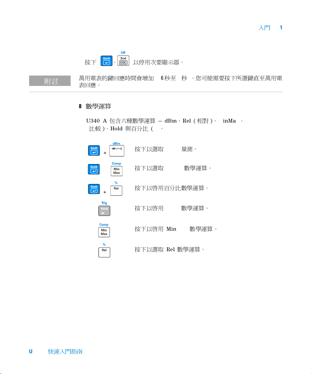
萬用電表的鍵回應時間會增加
表回應。
8
數學運算
U3401A
比較)、
(
包含六種數學運算
Hold
與百分比
+
+
+
(%)
按下以選取
按下以選取
按下以啟用百分比數學運算。
按下以啟用
按下以啟用
(0.6 秒至 1 秒)
— dBm、Rel (
。
dBm
Comp
Hold
MinMax
量測。
數學運算。
數學運算。
。您可能需要按下所選鍵直至萬用電
相對)、
數學運算。
MinMax、Comp
U3401A
快速入門指南
按下以選取
Rel
數學運算。
7
Page 48

1
入門
下表概述了可以與每個量測功能配合使用的數學運算。
量測功能
DCV
DCI
電阻
ACV
ACI
頻率
二極體/導通
dBm Rel Min Max Comp Hold %
✔✔✔✔✔ ✔✔
- ✔✔✔✔ ✔ ✔
--✔✔✔ ✔✔
✔✔✔✔✔ ✔✔
- ✔✔✔✔ ✔ ✔
- ✔✔✔✔ ✔ ✔
--✔✔✔ ✔✔
如需每個數學運算的詳細運算過程,請參閱 《
指南》。
有關詳細資訊
9
《
算與設定功能表
架
Agilent U3401A
安裝
說明與可更換的零件資訊。
使用者及維修指南》包含有關前端面板、量測功能、數學運
(
允許您自訂儀器設定) 的詳細資訊。它還包含產品規格、機
允許的數學運算
Agilent U3401A
使用者及維修
8 U3401A
快速入門指南
Page 49

www.agilent.com
與我們聯絡
若
要
取得服務、保固或技術支援幫助,請撥
打以下電話號碼聯絡我們
美國:
(
電話
) 800 829 4444 (傳真) 800 829 4433
加拿大:
(
電話
) 877 894 4414 (傳真) 800 746 4866
中國:
(
電話
) 800 810 0189 (傳真) 800 820 2816
歐洲:
(
電話
) 31 20 547 2111
日本:
(
電話
) (81) 426 56 7832
傳真
) (81) 426 56 7840
(
韓國:
(
電話
) (080) 769 0800 (
拉丁美洲:
(
電話
) (305) 269 7500
中國台灣地區:
(
電話
) 0800 047 866 (傳真) 0800 286 331
其他亞太地區國家:
(
電話
) (65) 6375 8100 (
:
傳真
) (080) 769 0900
傳真
) (65) 6755 0042
或請造訪
www.agilent.com/find/assist
本文件中的產品規格和描述,如有變更恕不
另行通知。請隨時造訪
是否有最新修訂內容。
Agilent
全球資訊網網站,網址為:
Agilent
網站,以瞭解
© Agilent Technologies, Inc. 2009
馬來西亞印製
2009 年 3 月 18
日,第一版
U3401-90019
Agilent Technologies
Page 50

Agilent U3401A
4 1/2
桁デュアル・
ディスプレイ・
マルチメータ
クイック・スタート・
ガイド
Agilent Technologies
Page 51

ご注意
注意
警告
© Agilent Technologies, Inc. 2009
米国および国際著作権法の規定に基づき、
Agilent Technologies, Inc.
書面による許可なしに、本書の内容をいかな
る手段でも(電子的記憶および読み出し、他
言語への翻訳を含む)複製することはできま
せん。
マニュアル・パーツ番号
U3401-90019
版
第1版、
2009年3月18
印刷:マレーシア
Agilent Technologies, Inc.
3501 Stevens Creek Blvd.
Santa Clara, CA 95051 USA
日
による事前の同意と
保証
本書の内容は「現状のまま」で提供さ
れており、改訂版では断りなく変更さ
れる場合があります。また、アジレン
ト・テクノロジー株式会社(以下「ア
ジレント」という)は、法律の許す限
りにおいて、本書およびここに記載さ
れているすべての情報に関して、特定
用途への適合性や市場商品力の黙示的
保証に限らず、一切の明示的保証も黙
示的保証もいたしません。アジレント
は本書または本書に記載された情報の
適用、実行、使用に関連して生じるエ
ラー、間接的及び付随的損害について
責任を負いません。アジレントとユー
ザが別途に締結した書面による契約の
中で本書の情報に適用される保証条件
が、これらの条件と矛盾する場合、別
途契約の保証条件が優先されます。
安全に関する注意事項
注意の表示は、危険を表します。
ここに示す操作手順や規則などを
正しく実行または遵守しないと、
製品の損傷または重要なデータの
損失を招くおそれがあります。指
定された条件を完全に理解し、そ
れが満たされていることを確認す
るまで、注意の指示より先に進ま
ないでください。
テクノロジー・ライセンス
本書に記載されたハードウエア及びソフト
ウエア製品は、ライセンス契約条件に基づき
提供されるものであり、そのライセンス契約
条件の範囲でのみ使用し、または方製するこ
とができます。
警告の表示は、危険を表します。
ここに示す操作手順や規則などを
正しく実行または遵守しないと、
怪我または死亡のおそれがありま
す。指定された条件を完全に理解
し、それが満たされていることを
権利の制限について
米国政府の権利の制限。連邦政府に付与され
るソフトウェア及びテクニカル・データの権
利には、エンド・ユーザ・カスタマに提供さ
れるカスタマの権利だけが含まれます。アジ
レントでは、ソフトウエアとテクニカル・
データにおけるこのカスタム商用ライセン
スを
FAR 12.211(Technical Data)と 12.212
(
Computer Software
合、
DFARS 252.227-7015(Technical Data Commercial Items
in Commercial Computer Software or Computer
Software Documentation
)に従って、国防省の場
)と
DFARS 227.7202-3(Rights
)に従って提供します。
確認するまで、警告の指示より先
に進まないでください。
ii U3401A
クイック・スタート・ガイド
Page 52

目次
フロント・パネルの概要
ディスプレイの概要
使用前の準備
電源コードを接続します
1
持ち運び用ハンドルを調整します
2
テスト・リードを入力端子に接続します
3
マルチメータをオンにします
4
機能を選択します
5
レンジを設定します
6
セカンダリ・ディスプレイの使用
7
演算機能
8
詳細
9
Å@4
Å@7
Å@8
Å@1
Å@2
Å@4
Å@6
Å@6
Å@4
Å@5
Å@5
Å@6
クイック・スタート・ガイド
U3401A
iii
Page 53

iv U3401A
クイック・スタート・ガイド
Page 54

入門
測定機能
キーパッド
セカンダリ・ディスプレイ
入力端子と
電流ヒューズ
オートレンジ、
手動レンジ、
コンパレータ操作
パワー・
オン/オフ・
スイッチ
演算機能
キーパッド
シフト
プライマリ・ディスプレイ
1
フロント・パネルの概要
クイック・スタート・ガイド
U3401A
1
Page 55

1 入門
ディスプレイの概要
図
すべてのセグメントが点灯した状態の
1-1
真空蛍光ディスプレイ(VFD)の非常に見やすいインジケータについては、以下の表で
説明します。
インジケータ 概要
プライマリ・ディスプレイ
測定速度:低速。
S
測定速度:中速。
M
測定速度:高速。
F
ピーク測定。
PEAK
データ・ホールド
HOLD
MIN
MAX
相対値
REL
dBm
4 2 W
オートレンジ
AUTO
直流
DC
交流
AC
DCAC
演算機能:プライマリ・ディスプレイに表示される最小値
MinMax
演算機能:プライマリ・ディスプレイに表示される最大値
MinMax
を基準にしたデシベル単位
1 mW
端子抵抗。
4端子/2
ダイオード・テスト
抵抗の可聴導通テスト
AC+DC
プライマリ・ディスプレイの極性、桁、小数点
U3401A
U3401A
U3401A
には適用されません
U3401A
U3401A
フル表示
VFD
には適用されません
には適用されません
には適用されません
には適用されません
摂氏温度単位。
°
C
°
F
電圧単位:mV、
mV
華氏温度単位。
には適用されません
U3401A
には適用されません
U3401A
V
2 U3401A
クイック・スタート・ガイド
Page 56

インジケータ 概要
電流単位:μA、mA、
μ
mA
μ
キャパシタンス単位: μF、nF、
mnF
Ω 抵抗単位:Ω、kΩ、MΩ
Mk
周波数単位:Hz、
MkHz
セカンダリ・ディスプレイ
プライマリ・ディスプレイの極性、桁、小数点
キャパシタンス単位:μF、nF、
μ
mnF
°C 摂氏温度単位。
華氏温度単位。
°
F
デューティ・サイクル測定
%
電圧単位:mV、
mV
μmA 電流単位:μA、mA、
シフト・モード
S
Ω 抵抗単位:Ω、kΩ、MΩ
Mk
セカンダリ・ディスプレイがオン
2ND
オートレンジ
AUTO
直流
DC
交流
AC
DCAC
比較操作
COMP
dBm
校正モード
CAL
外部。
EXT
トリガ・モード
TRIG
リモート・インタフェース制御。校正専用
REMOTE
ローカル・モード
LOCAL
機器ステートを保存。
STO
保存されている機器ステートをリコール。
RCL
AC+DC
を基準にしたデシベル単位
1 mW
U3401A
A
mF
kHz、MHz
mF
には適用されません
U3401A
には適用されません
U3401A
V
A
には適用されません
には適用されません
U3401A
には適用されません
U3401A
U3401A
入門
には適用されません
1
クイック・スタート・ガイド
U3401A
3
Page 57

1 入門
注意
使用前の準備
ここでは、マルチメータの操作方法の基本手順について詳細に説明します。
電源コードを接続します
1
電源電圧スイッチとヒューズは、出荷先の国に合わせて工場で設定されています。
持ち運び用ハンドルを調整します
2
ハンドルの側面をつかんで、外側(下の赤い矢印で示す方向)にひっぱります。
次に、ハンドルを必要な位置まで動かします。
4 U3401A
クイック・スタート・ガイド
Page 58

テスト・リードを入力端子に接続します
+
AC
またはDC電圧、周波数、抵抗測定および
ダイオード/導通テスト
_
+
_
最大
10 A RMS
の
AC
またはDC電流
+
_
AC
またはDC電流
3
入門
1
クイック・スタート・ガイド
U3401A
マルチメータをオンにします
4
を押してマルチメータをオンにします。マルチメータがパワー・オン・セルフ
テストを実行しているあいだ、フロント・パネル・ディスプレイが明るくなります。
マルチメータの電源投入直後は、DC電圧機能に設定され、オートレンジがオンの状
態になっています。代表的なディスプレイを示します。
5
Page 59

1 入門
機能を選択します
5
次のキーのいずれかを押して、測定機能を選択します。
レンジを設定します
6
ほとんどの測定機能では、オートレンジ機能を使用すると、マルチメータがレンジを
自動的に選択します。手動レンジを使用すると、固定レンジを選択できます。オート
レンジ機能を選択している場合は、AUTOインジケータが点灯します。
オートレンジを選択し、手動レンジをオフにします。押すと、手動
レンジとオートレンジが切り替わります。
より高いレンジを選択し、オートレンジをオフにします。
より低いレンジを選択し、オートレンジをオフにします。
セカンダリ・ディスプレイの使用
7
を押し、 、 、 、 、 などの指定されたファンクショ
ン・キーを押して、セカンダリ・ディスプレイ・モードをオンにします。
6 U3401A
クイック・スタート・ガイド
Page 60

入門
注意
、 を押して、 セカンダリ・ディスプレイをオフにします。
マルチメータがデュアル・ディスプレイ・モードの場合は、キーの応答時間が長くなり
ます(
0.6 sから1 s
ます。
演算機能
8
U3401Aには、dBm、Rel(相対)、MinMax、Comp(比較)、Hold、Percentage(%)
の6つの演算機能があります。
)。マルチメータが応答するまで選択したキーを押し続ける必要があり
1
+
+
+
dBm測定を選択します。
Comp演算機能を選択します。
Percentage演算機能をオンにします。
Hold演算機能をオンにします。
MinMax演算機能をオンにします。
Rel演算機能を選択します。
クイック・スタート・ガイド
U3401A
7
Page 61

1 入門
以下の表に、各測定機能と一緒に使用できる演算機能のサマリを示します。
測定機能
DCV
DCI
抵抗
ACV
ACI
周波数
ダイオード/導通
dBm Rel Min Max Comp Hold %
✔ ✔ ✔ ✔ ✔ ✔ ✔
- ✔ ✔ ✔ ✔ ✔ ✔
- - ✔ ✔ ✔ ✔ ✔
✔ ✔ ✔ ✔ ✔ ✔ ✔
- ✔ ✔ ✔ ✔ ✔ ✔
- ✔ ✔ ✔ ✔ ✔ ✔
- - ✔ ✔ ✔ ✔ ✔
使用可能な演算機能
各演算機能の詳細な操作手順については、『Agilent U3401A User’s and Service
Guide』を参照してください。
詳細
9
『Agilent U3401A User’s and Service Guide』には、フロント・パネル、測定機能、
演算機能、設定メニュー(測定器の設定をカスタマイズ可能)についての詳細情報が
含まれています。製品の仕様、ラック・マウント手順・インタフェース、交換部品に
関する情報もあります。
8 U3401A
クイック・スタート・ガイド
Page 62

www.agilent.com
Contact us
o obtain service, warranty or technical support
T
assistance, contact us at the
following phone numbers:
United States:
(tel) 800 829 4444 (fax) 800 829 4433
Canada:
(tel) 877 894 4414 (fax) 800 746 4866
China:
(tel) 800 810 0189 (fax) 800 820 2816
Europe:
(tel) 31 20 547 2111
Japan:
(tel) (81) 426 56 7832 (fax) (81) 426 56 7840
Korea:
(tel) (080) 769 0800 (fax) (080) 769 0900
Latin America:
(tel) (305) 269 7500
Ta i w a n :
(tel) 0800 047 866 (fax) 0800 286 331
Other Asia Pacific Countries:
(tel) (65) 6375 8100 (fax) (65) 6755 0042
Or visit Agilent worlwide Web at:
www.agilent.com/find/assist
Product specifications and descriptions in this
document are subject to change without notice.
Always refer to the Agilent Web site for the latest
revision.
© Agilent Technologies, Inc. 2009
Printed in Malaysia
First Edition, March 18, 2009
U3401-90019
Agilent Technologies
 Loading...