

Page 1
Agilent
U2531A USB Simultaneous Sampling DAQ in
Power Measurement Unit Monitoring
Application Note
Page 2
Introduction
Mobile devices are getting more and
more popular. The mobile phone in
the market now has become a pocket
media center. It contains at least a
digital still camera, video conference
functionality, an MP3 player with
simulated surround sound, and a
color Internet browser coupled with
3-D gaming capability. Mobile phones
are continuously equipped with an
increasing number of functions, and
newer phones will come with higher
resolution cameras, adding various
kinds of storage attachment, mobile
television and personal security
devices such as thumbprint sensors.
Mobile phone power management
thus, becomes one of the most
signifi cant engineering challenges.
Other than mobile phones, the other
portable devices like handheld devices,
Personal Digital Assistants (PDAs),
Smart Phones, Portable Multimedia
Players (PMPs), MP3 players, Gaming,
and Global Positioning System (GPS)
also present increasingly sophisticated
functionality and application
requirements.
To achieve seamless playing of music, gaming, and voice and video call on
the mobile phones, it is necessary that the power outputs from the power
management unit remain stable. This will ensure a good customer experience
arising out of using the mobile devices.
For this reason, it is necessary to have a quick and easy design validation of
the power management unit by monitoring the stability of the power inputs and
outputs while switching between the functions of the PMU. The PMU typically
has an input and a few outputs. The parameters to be measured of each channel
will be both the voltage and current. In this particular application, the PMU
has an input and four output ports. Thus, if both voltage and current are to be
monitored for each port, then a total of ten measurement channels are needed.
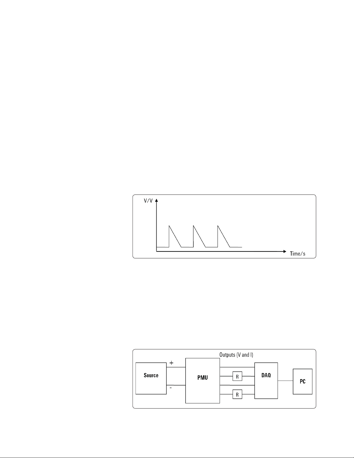
PMU Monitoring
In the following sections, this application note focuses on how a PMU (in this
case a PMU with one input port and four output ports) can be monitored. The
purpose of this application is to monitor the channels to determine if the outputs
of the PMU are sending out stable signals when the different functions of the
PMU are executed during design validation. This can be seen easily by detecting
if spikes are present, as shown in Figure 1.
With increasing demands of
functionality and application
requirements, there will also be
an increasing power management
complexity of the overall system.
The drive for these portable device
manufacturers is then moving towards
a power management solution that
is lower in total system cost, and
is fl exible and scalable enough to
manage these demanding power
requirements. The power management
unit (PMU) would be expected to have
different voltage and current outputs
as well to interface to the different
functionality blocks. This voltage
range could range from millivolts to up
to 3.3 V. The current could be in the
range of milliamperes.
Figure 1. Graph indicated a transient signal detected.
To simulate an aging process and to run through all the functionality of the PMU,
the duration of the test will take several hours. Since both voltage and current
measurements need to be made for each port, the total number of channels
needed would be ten. In this particular test, three data acquisition (DAQ) devices
like the U2531A 2 MSa/s, 4-channel simultaneous sampling multifunction DAQ
device and the U2781A 6-Slot USB modular instrument chassis will be most
suitable. Since the maximum voltage output for this particular PMU is 3.3 V, it
can be connected directly to the input of the DAQ device. The current can be
easily measured by measuring the voltage across a resistor. The block diagram
in Figure 2 illustrates how this test is conducted.
Figure 2. Block diagram shows the test setup of PMU monitoring.
2
Page 3
In this application, the program is written in Agilent VEE Pro to control the DAQ
devices in acquiring the voltage and current as shown in Figure 3.
Figure 3. Windows shown is the VEE test program.
The functionality of the PMU is controlled by its fi rmware. In this particular
application, the VEE program is used to control the DAQ devices with regard
to the monitoring of the different channels. In addition, a separate routine is
written to run through the functionality of the PMU. Alternatively, another
routine can be written to control the DAQ and the fi rmware together and to
easily establish a correlation between the DAQ results and the functionality.
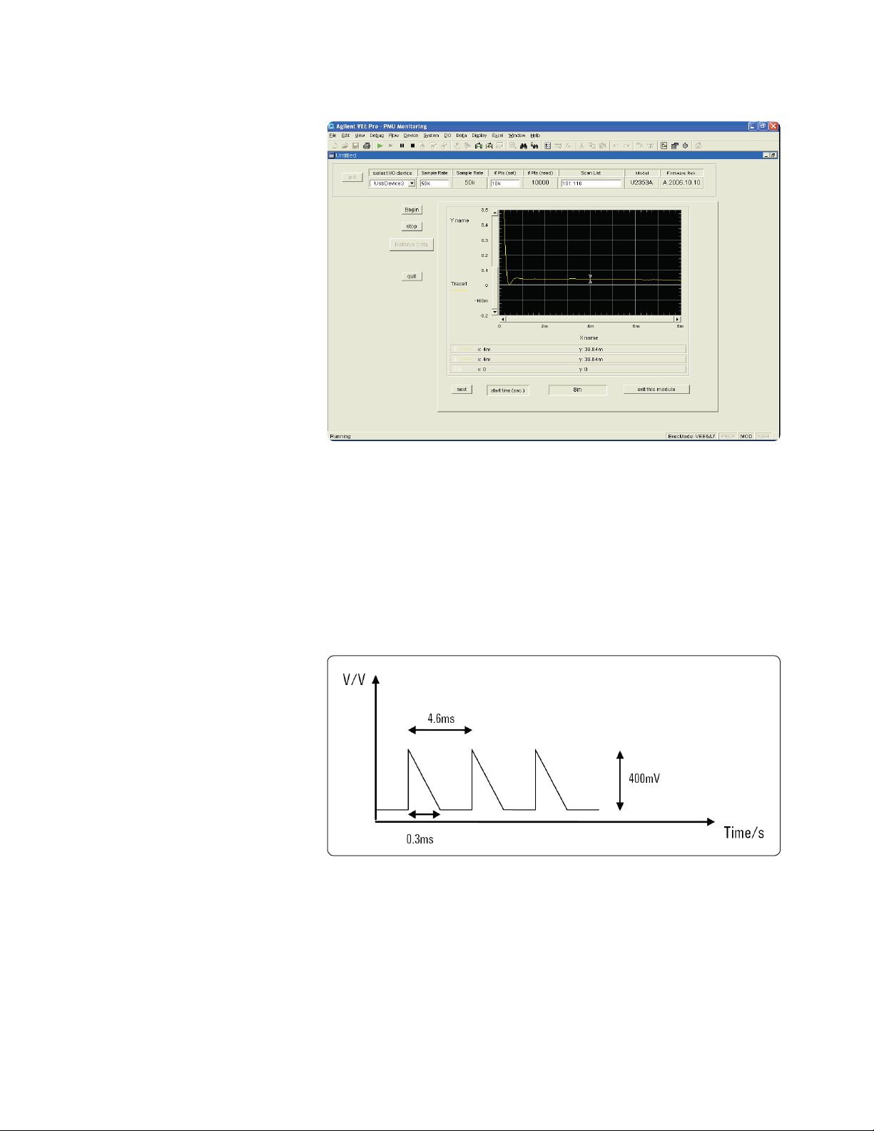
During channel monitoring in this particular application a glitch is detected in
one of the channels, as shown in Figure 4.
Figure 4. The graph shows an actual glitch detected by the DAQ.
3
Page 4

The duration of the spike is 0.3 ms. In fact, with the 2 MSa/s sampling rate DAQ,
and the recommendation that the sampling rate employed by the DAQ (or the
test system) should be fi ve times the sampling rate of the signal, the maximum
glitch that can be detected is 2.5 us. In this application, the absolute voltage
is actually not as important since the main purpose of the application is to
monitor the presence of spikes. The DAQ measurements and functionality test
were carried out at the same time, and since it can be determined when a spike
occurs once the data acquisition process has started, it is also possible to easily
and quickly determine the actual status and functionality details of the PMU at
that point in time. Based on this information, the troubleshooting process can be
related to the exact time and situation at which the problem occurred.
Conclusion
With the growing popularity for portable devices, it is necessary to have a quick
and easy design validation of the power management unit. The objective of
monitoring the PMU for stable input and outputs can be achieved using Agilent’s
DAQ. This way it is possible to reduce the time required to resolve the problem.
This is done through a low cost DAQ solution.
References
[1] Agilent U2500A Series USB Simultaneous Multifunction Data Acquisition
Devices User’s Guide, Part Number U2351-90002.
4
Page 5

Agilent Email Updates
t
www.agilent.com/fi nd/emailupdates
Get the latest information on the products and applications you select.
Agilent Direc
www.agilent.com/fi nd/agilentdirect
Quickly choose and use your test
equipment solutions with confi dence.
Agilent
Open
www.agilent.com/fi nd/open
Agilent Open simplifi es the process of connecting and
programming test systems to help engineers design,
validate and manufacture electronic products. Agilent
offers open connectivity for a broad range of systemready instruments, open industry software, PC-standard
I/O and global support, which are combined to more
easily integrate test system development.
Remove all doubt
Our repair and calibration services will get your
equipment back to you, performing like new,
when promised. You will get full value out of your
Agilent equipment throughout its lifetime. Your
equipment will be serviced by Agilent-trained
technicians using the latest factory calibration
procedures, automated repair diagnostics and
genuine parts. You will always have the utmost
confi dence in your measurements.
Agilent offers a wide range of additional expert
test and measurement services for your equipment, including initial start-up assistance onsite
education and training, as well as design, system
integration, and project management.
For more information on repair and
calibration services, go to
www.agilent.com/find/removealldoubt
www.agilent.com
For more information on Agilent Technologies’
products, applications or services, please contact
your local Agilent office. The complete list is
available at:
www.agilent.com/find/contactus
Phone or Fax
United States:
(tel) 800 829 4444
(fax) 800 829 4433
Canada:
(tel) 877 894 4414
(fax) 800 746 4866
China:
(tel) 800 810 0189
(fax) 800 820 2816
Europe:
(tel) 31 20 547 2111
Japan:
(tel) (81) 426 56 7832
(fax) (81) 426 56 7840
Korea:
(tel) (080) 769 0800
(fax) (080) 769 0900
Latin America:
(tel) (305) 269 7500
Taiwan:
(tel) 0800 047 866
(fax) 0800 286 331
Other Asia Pacifi c Countries:
(tel) (65) 6375 8100
(fax) (65) 6755 0042
Email: tm_ap@agilent.com
Revised: 11/08/06
Product specifi cations and descriptions
in this document are subject to change
without notice.
© Agilent Technologies, Inc. 2007
Printed in USA, October 31, 2007
5989-7422EN
 Loading...