

Page 1

Agilent U2300A Series USB Multifunction Data Acquisition Devices
Service Guide
Agilent Technologies
Page 2

Notices
© Agilent Technologies, Inc. 2007 - 2010
No p art o f this manu al may be re produce d in
any form or by any means (including electronic storage and retrieval or translation
into a foreign language) without prior agreement and written consent from Agilent
Technologies, Inc. as governed by United
States and international copyright laws.
Manual Part Number
U2351-90203
Edition
Second Edition, August 23, 2010
Printed in Malaysia
Agilent Technologies, Inc.
Bayan Lepas Free Industrial Zone,
11900 Penang, Malaysia
Warranty
The material contained in this document is provided “as is,” and is subject to being changed, without notice,
in future editions. Further, to the maximum extent permitted by applicable
law, Agilent disclaims all warranties,
either express or implied, with regard
to this manual and any information
contained herein, including but not
limited to the implied warranties of
merchantability and fitness for a particular purpose. Agilent shall not be
liable for errors or for incidental or
consequential damages in connection with the furnishing, use, or performance of this document or of any
information contained herein. Should
Agilent and the user have a separate
written agreement with warranty
terms covering the material in this
document that conflict with these
terms, the warranty terms in the separate agreement shall control.
Technology Licenses
The hardware and/or software described in
this document are furnished under a license
and may be used or copied only in accordance with the terms of such license.
Restricted Rights Legend
U.S. Government Restricted Rights. Software and technical data rights granted to
the federal government include only those
rights customarily provided to end user customers. Agilent provides this customary
commercial license in Software and technical data pursuant to FAR 12.211 (Technical
Data) and 12.212 (Computer Software) and,
for the Department of Defense, DFARS
252.227-7015 (Technical Data - Commercial
Items) and DFARS 227.7202-3 (Rights in
Commercial Computer Software or Computer Software Documentation).
Safety Notices
CAUTION
A CAUTION notice denotes a hazard. It calls attention to an operating procedure, practice, or the like
that, if not correctly performed or
adhered to, could result in damage
to the product or loss of important
data. Do not proceed beyond a
CAUTION notice until the indicated
conditions are fully understood and
met.
WARNING
A WARNING notice denotes a
hazard. It calls attention to an
operating procedure, practice, or
the like that, if not correctly performed or adhered to, could result
in personal injury or death. Do not
proceed beyond a WARNING
notice until the indicated conditions are fully understood and
met.
II U2300A Series DAQ Service Guide
Page 3
Safety Information
The following general safety precautions must be observed during all phases of this instrument. Failure to comply
with these precautions or with specific warnings elsewhere in this manual violates safety standards of design,
manufacture, and intended use of the instrument. Agilent Technologies, Inc. assumes no liability for the
customer’s failure to comply with these requirements.
Safety Symbols
The following symbols indicate that precautions must be taken to maintain safe
operation of the instrument.
Direct current
Warni ng
Regulatory Markings
The CE mark shows that the product complies with all the
relevant European Legal Directives (if accompanied by a year, it
signifies when the design was proven).
The CSA mark is a registered trademark of the Canadian Standards Association. A CSA mark with the indicators "C" and "US"
means that the product is certified for both the U.S. and Canadian
markets, to the applicable American and Canadian standards.
The UL Mark is a registered trademark of Underwriters Laboratories Inc. UL listing mark with the indicators "C" and "US” indicates the product compliance with both Canadian and U.S.
requirements.
The C-tick mark is a registered trademark of the Spectrum Management Agency of Australia. This signifies compliance with the
Australian EMC Framework regulations under the terms of the
Radio Communications Act of 1992.
U2300A Series DAQ Service Guide III
Page 4

General Safety Information
WARNING
CAUTION
• Do not use the device if it is damaged.Before you use the device,
inspect the case. Look for cracks or missing plastic. Do not operate the
device around explosive gas, vapor or dust.
• Do not apply more than the rated voltage (as marked on the device)
between terminals, or between terminal and external ground.
• Always use the device with the cables provided.
• Observe all markings on the device before connecting to the device.
• Turn off the device and application system power before connecting to
the I/O terminals.
• When servicing the device, use only specified replacement parts.
• Do not operate the device with the removable cover removed or
loosened.
• Do not connect any cables and terminal block prior to performing
self-test process.
• Use only the power adapter supplied by the manufacturer to avoid any
unexpected hazards.
• Do not load the output terminals above the specified current limits.
Applying excessive voltage or overloading the device will cause
irreversible damage to the circuitry.
• Applying excessive voltage or overloading the input terminal will
damage the device permanently.
• If the device is used in a manner not specified by the manufacturer, the
protection provided by the device may be impaired.
• Always use dry cloth to clean the device. Do not use ethyl alcohol or
any other volatile liquid to clean the device.
• Do not permit any blockage of the ventilation holes of the device.
IV U2300A Series DAQ Service Guide
Page 5
Waste Electrical and Electronic Equipment (WEEE) Directive 2002/96/EC
This instrument complies with the WEEE Directive (2002/96/EC) marking
requirement. This affixed product label indicates that you must not discard this
electrical/electronic product in domestic household waste.
Product Category:
With reference to the equipment types in the WEEE directive Annex 1, this
instrument is classified as a “Monitoring and Control Instrument” product.
The affixed product label is shown as below:
Do not dispose in domestic household waste
To return this unwanted instrument, contact your nearest Agilent office, or visit:
http://www.agilent.com/environment/product
for more information.
U2300A Series DAQ Service Guide V
Page 6

In This Guide...
1 Characteristics and Specifications 1
This chapter specifies the product specifications and electrical
measurement specifications of the U2300A Series USB
Multifunction DAQ devices.
2 Calibration 15
This chapter describes the step- by- step calibration procedures that
covers hardware setup, self calibration, performance verification
procedures and adjustment procedures.
3 Dismantle Procedures 41
This chapter shows the step- by- step disassemble procedures and
list the available replacement parts together with its part number
for U2300A Series USB Multifunction DAQ devices.
4 Troubleshooting and Self-Test Procedures 47
This chapter includes the information on general troubleshooting
hints and self test procedures for the U2300A Series USB
Multifunction DAQ devices.
A Connector Pins Configuration 51
All the U2300A Series USB Multifunction DAQ devices pins
configuration are provided in the appendix.
B Test Limits 57
This appendix provides the test limits of analog input and analog
output for the U2300A Series USB Multifunction DAQ devices.
VI U2300A Series DAQ Service Guide
Page 7

Contents
Contents
1 Characteristics and Specifications 1
Product Specifications 2
Electrical Measurement Specifications 10
2 Calibration 15
Introduction 16
Types Of Signal Sources 17
Input Configurations 18
Hardware Connection 22
Self-Calibration 26
Adjustment Procedures 32
Performance Verification Procedure 34
A/D Data Conversion 38
3 Dismantle Procedures 41
General Disassemble 42
Replacement Parts 46
4 Troubleshooting and Self-Test Procedures 47
Troubleshooting 48
Self-Test Procedures 49
A Connector Pins Configuration 51
Pins Configuration for U2331A, U2355A and U2356A 52
Pins Configuration for U2351A, U2352A, U2353A and U2354A 53
B Tes t L im it s 57
Analog Input 58
U2300A Series DAQ Service Guide VII
Page 8

Contents
Analog Output 62
VIII U2300A Series DAQ Service Guide
Page 9

Agilent U2300A Series Multifunction USB DAQ
Service Guide
1
Characteristics and Specifications
Product Specifications 2
Electrical Measurement Specifications 10
This chapter specifies the specifications of the U2300A DAQ
devices.
Agilent Technologies
1
Page 10
1 Characteristics and Specifications
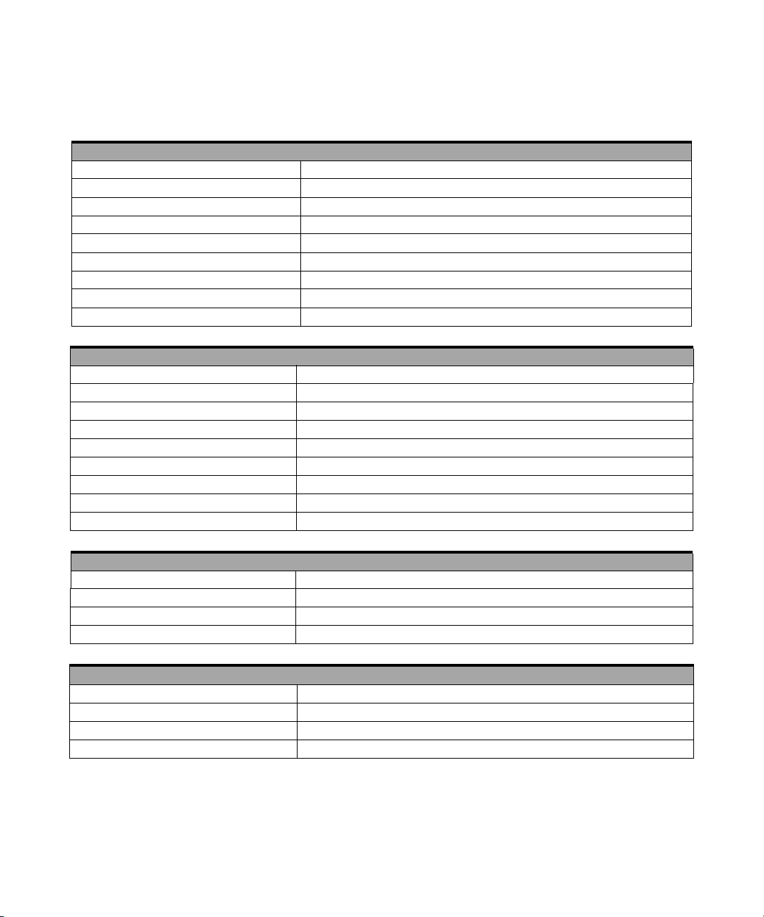
Product Specifications
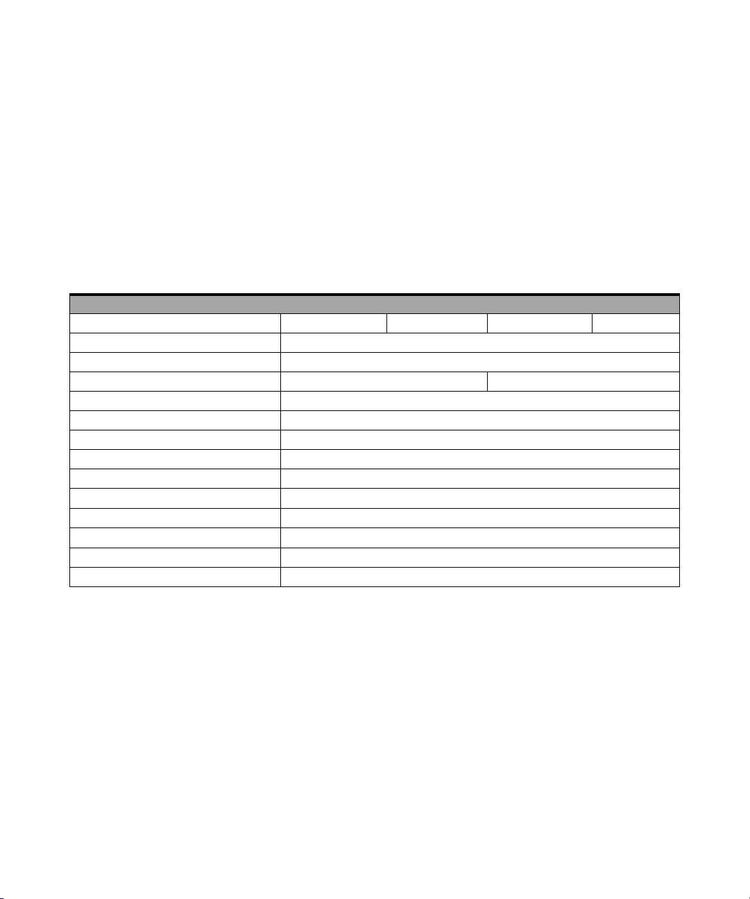
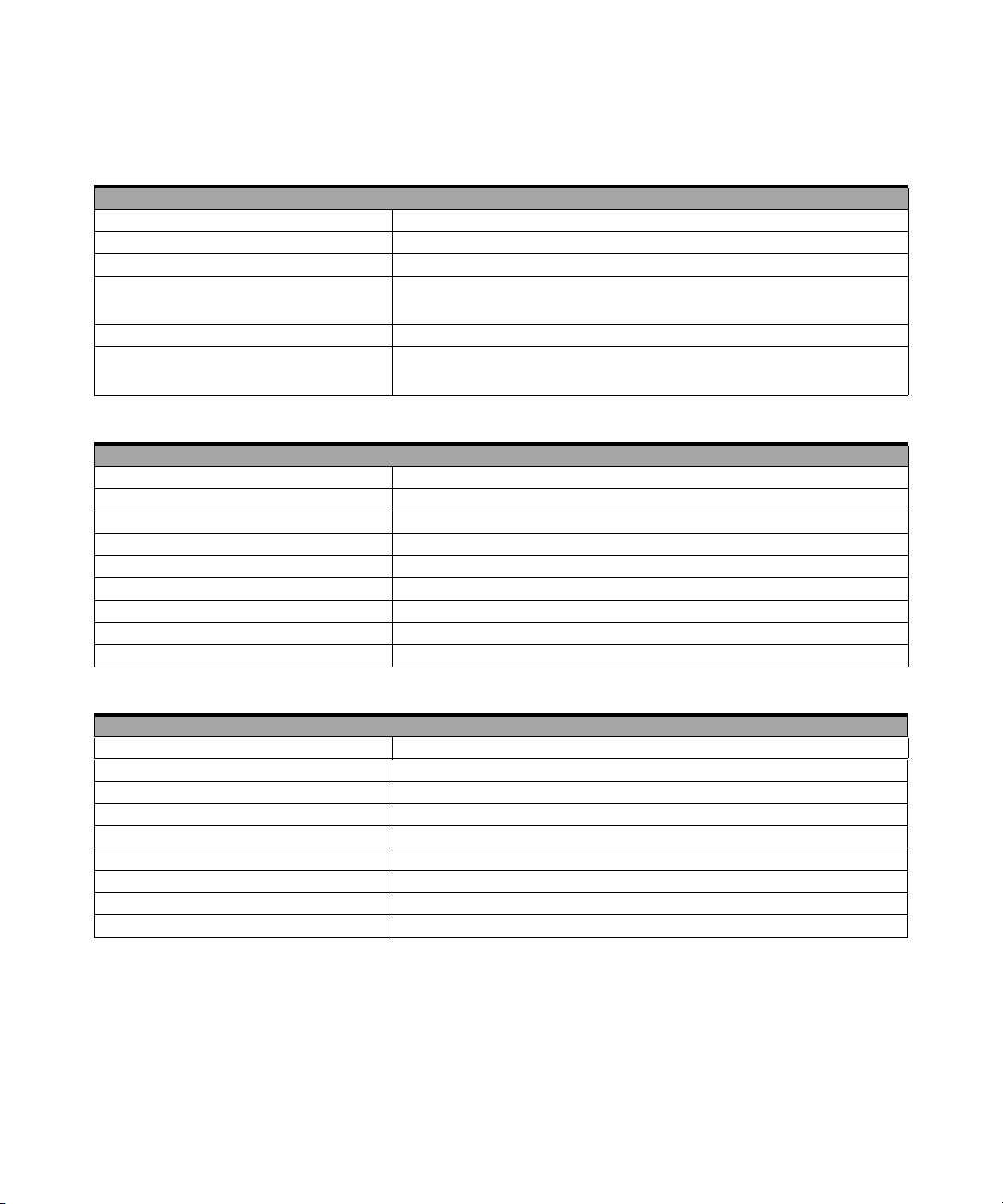
Basic Multifunction DAQ Device Specifications
Tab l e 1 - 1 Product specifications for basic multifunction DAQ device (U2351A,
U2352A, U2353A, and U2354A)
Analog Input
Model Number U2351A U2352A U2353A U2354A
Resolution 16 bits, no missing codes
Number of channels 16 SE/8 DI (software selectable/channel)
Maximum sampling rate 250 kSa/s 500 kSa/s
Scan list memory Up to 100 selectable channels entries
Programmable bipolar input range ±10 V, ±5 V, ±2.5 V, ±1.25 V
Programmable unipolar input range 0 to 10 V, 0 to 5 V, 0 to 2.5 V, 0 to 1.25 V
Input coupling DC
Input impedance 1 GΩ / 100 pF
Operational common mode voltage range
Overvoltage protection Power on: Continuous ±30 V, Power off: Continuous ±15 V
Trig g e r s o u rc e s
Trigger modes Pre- trigger, delay-trigger, post-trigger and middle-trigger
FIFO buffer size Up to 8 MSa
External analog/digital trigger, SSI/star trigger
±7.5 V maximum
[4]
[1]
2 U2300A Series DAQ Service Guide
Page 11
Characteristics and Specifications 1
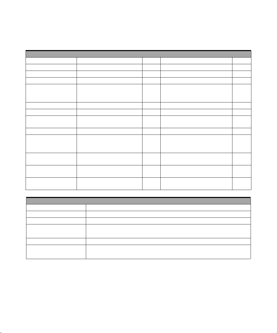
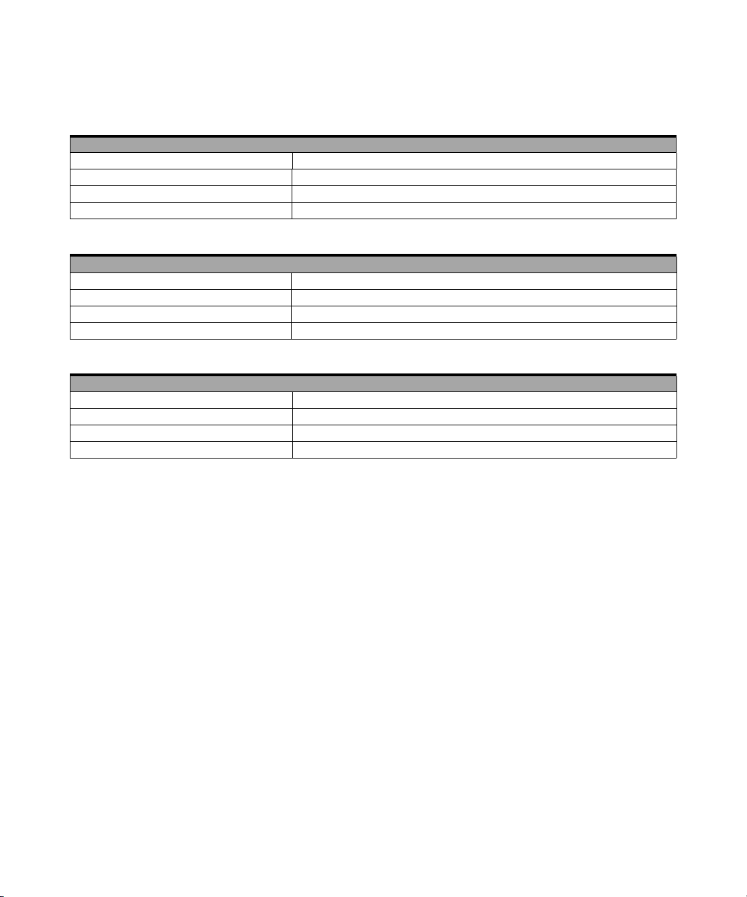
Analog Output
Model Number U2351A U2352A U2353A U2354A
Resolution 16 bits N/A 16 bits N/A
Number of channels 2 N/A 2 N/A
Maximum update rate 1 MSa/s N/A 1 MSa/s N/A
Output ranges 0 to 10 V, ±10 V,
0 to AO_EXT_REF,
±AO_EXT_REF
[2]
N/A 0 to 10 V, ±10 V,
0 to AO_EXT_REF,
±AO_EXT_REF
[2]
Output coupling DC N/A DC N/A
Output impedance 0.1 Ω Typical N/A 0.1 Ω Typical N/A
Stability Any passive load
up to 1500 pF
N/A Any passive load
up to 1500 pF
Power-on state 0 V steady state N/A 0 V steady state N/A
Trigger sources External
analog/digital trigger,
SSI/star trigger
[1]
Trigger modes Post-trigger and
delay-trigger
FIFO buffer size 1 channel: Maximum 8 MSa
2 channels: Maximum 4 MSa/ch
Function generation mode Sine-wave, square-wave, triangle,
sawtooth and noise waveform
N/A External
analog/digital trigger,
SSI/star trigger
[1]
N/A Post-trigger and
delay-trigger
N/A 1 channel: Maximum 8 MSa
2 channels: Maximum 4 MSa/ch
N/A Sine-wave, square-wave, triangle,
sawtooth and noise waveform
N/A
N/A
N/A
N/A
N/A
N/A
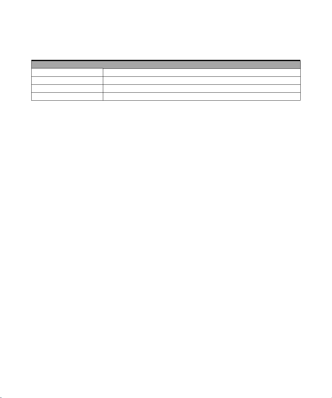
Digital I/O
Model Number U2351A | U2352A | U2353A | U2354A
Number of bits 24-bit programmable input/output
Compatibility TTL
Input voltage V
= 0.7 V maximum, IIL = 10 µA maximum
IL
VIH = 2.0 V minimum, IIH = 10 µA maximum
Input voltage range –0.5 V to +5.5 V
Output voltage V
= 0.45 V maximum, IOL = 8 mA maximum
OL
= 2.4 V minimum, IOH = 400 µA maximum
V
OH
U2300A Series DAQ Service Guide 3
Page 12
1 Characteristics and Specifications
General Purpose Digital Counter
Model Number U2351A | U2352A | U2353A | U2354A
Maximum count (2³¹-1) bits
Number of channels Two independent up/down counter
Compatibility TTL
Clock source Internal or external
Base clock available 48 MHz
Maximum clock source frequency 12 MHz
Input frequency range 0.1 Hz to 6 MHz at 50% duty cycle
Pulse width measurement range 0.167 µs to 178.956 s
Analog Trigger
Model Number U2351A | U2352A | U2353A | U2354A
Trigger source All analog input channels, External analog trigger (EXTA_TRIG)
Trigger level ±Full Scale for internal; ±10 V for external
Trigger conditions Above high, below low and window (software selectable)
Trigger level resolution 8 bits
Bandwidth 400 kHz
Input Impedance for EXTA_TRIG 20 kΩ
Coupling DC
Overvoltage Protection Continuous for ± 35 V maximum
Digital Trigger
Model Number U2351A | U2352A | U2353A | U2354A
Compatibility TTL/CMOS
Response Rising or falling edge
Pulse width 20 ns minimum
Calibration
[3]
Model Number U2351A | U2352A | U2353A | U2354A
On board reference voltage 5 V
Temperature drift ±2 ppm/°C
Stability ±6 ppm/1000 hours
4 U2300A Series DAQ Service Guide
Page 13
Characteristics and Specifications 1
General
Model Number U2351A | U2352A | U2353A | U2354A
Remote interface Hi-Speed USB 2.0
Device class USBTMC Class Device
Programmable interface Standard Commands for Programmable Instruments (SCPI) and IVI-COM
[1] System Synchronous Interface (SSI) and Star-trigger commands are used when
modular devices are used in instrument chassis.
[2] Maximum external reference voltage for analog output (AO_EXT_REF) is ±10 V.
[3] 20 minutes warm-up time is recommended.
[4] Refer to Figure 1-1 for more information.
U2300A Series DAQ Service Guide 5
Page 14
1 Characteristics and Specifications
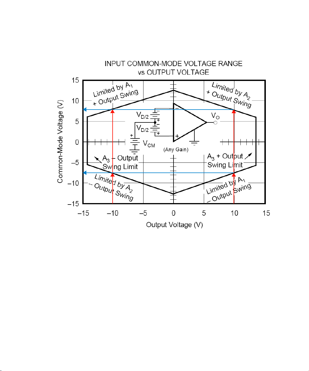
7.5
-7.5
Figure 1-1 Operational common mode voltage range
This graph shows that the common mode voltage range is tightly
linked with the output voltage. The output voltage range of the
DAQ devices is ±10 V. Therefore, the common mode voltage range
is ±7.5 V. Any operation beyond these voltage ranges may produce
unexpected and unreliable results, and should be avoided.
6 U2300A Series DAQ Service Guide
Page 15
Characteristics and Specifications 1
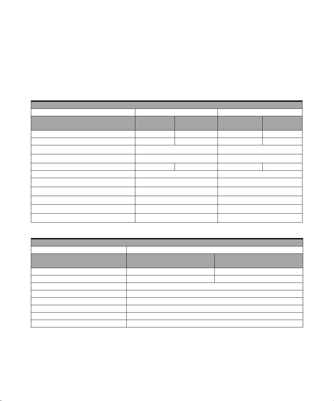
High Density Multifunction DAQ Device Specifications
Tab l e 1 - 2 Product specifications for high density multifunction DAQ device
(U2355A, U2356A and U2331A)
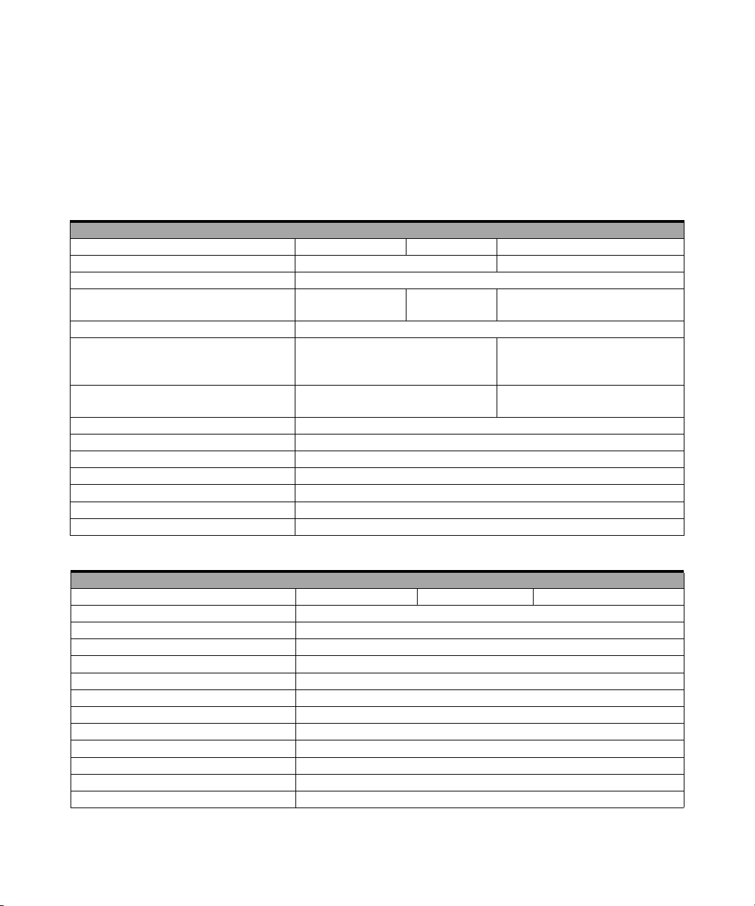
Analog Input
Model Number U2355A U2356A U2331A
Resolution 16 bits, no missing codes 12 bits, no missing codes
Number of channels 64 SE/32 DI (software selectable/channel)
Maximum sampling rate 250 kSa/s 500 kSa/s 3 MSa/s (single channel)
1 MSa/s (multi channels)
Scan list memory Up to 100 selectable channels entries
Programmable bipolar input range ±10 V, ±5 V, ±2.5 V, ±1.25 V ±10 V, ±5 V, ±2.5 V,
±1.25 V, ±1 V, ±0.5 V,
±0 .25 V, ±0.2 V, ±0.0 5 V
Programmable unipolar input range 0 to 10 V, 0-5 V, 0-2.5 V, 0-1.25 V 0-10 V, 0-5 V, 0-4 V, 0-2.5 V, 0-2 V,
0-1 V, 0-0.5 V, 0-0.4 V, 0-0.1V
Input coupling DC
Input impedance 1 GΩ / 100 pF
Operational common mode voltage range ±7.5 V maximum
Overvoltage protection Power on: Continuous ±30 V, Power off: Continuous ±15 V
Trig g e r s o u rc e s
External analog/digital trigger, SSI/star trigger
Trigger modes Pre-trigger, delay-trigger, post-trigger and middle-trigger
FIFO buffer size Up to 8 MSa
[1]
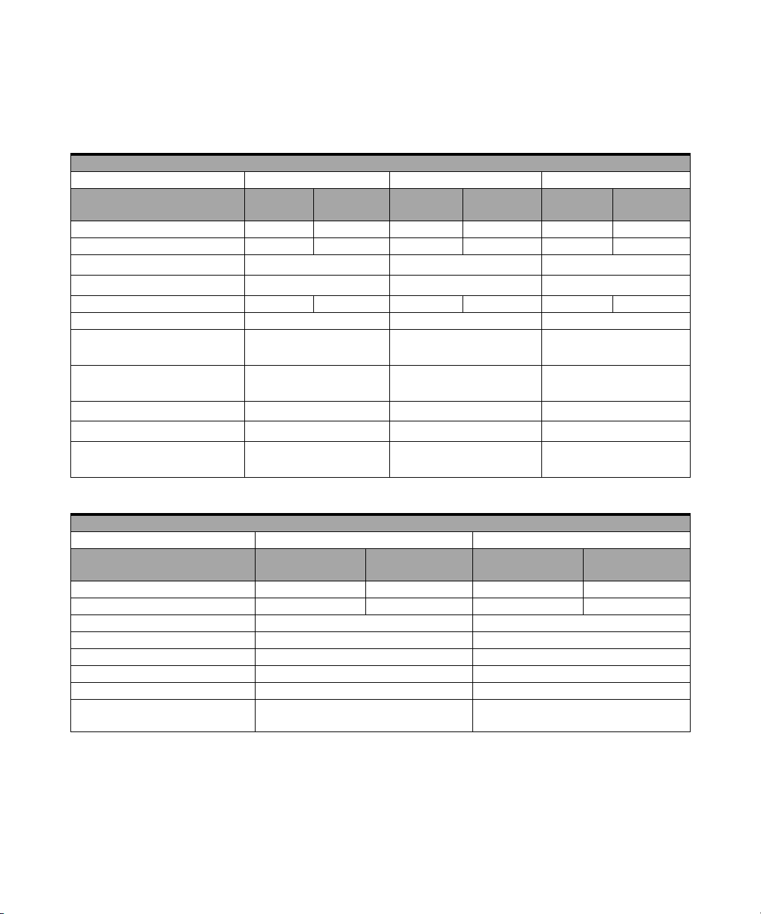
Analog Output
Model Number U2355A U2356A U2331A
Resolution 12 bits
Number of channels 2
Maximum update rate 1 MSa/s
Output ranges
0 to 10 V, ±10 V, 0 to AO_EXT_REF, ±AO_EXT_REF
[2]
Output coupling DC
Output impedance 0.1 Ω Typical
Stability Any passive load up to 1500 pF
Power on state 0 V steady state
Trigger sources
External analog/digital trigger, SSI/star trigger
[1]
Trigger modes Post-trigger and delay-trigger
FIFO buffer size 1 channel: Maximum 8 MSa, 2 channels: Maximum 4 MSa/ch
Function generation mode Sine-wave, square-wave, triangle, sawtooth and noise waveform
U2300A Series DAQ Service Guide 7
Page 16
1 Characteristics and Specifications
Digital I/O
Model Number U2355A | U2356A | U2331A
Number of bits 24-bit programmable input/output
Compatibility TTL
Input voltage V
Input voltage range –0.5 V to +5.5 V
Output voltage V
General Purpose Digital Counter
Model Number U2355A | U2356A | U2331A
Maximum count (2³¹-1) bits
Number of channels Two independent up/down counter
Compatibility TTL
Clock source Internal or external
Base clock available 48 MHz
Maximum clock source frequency 12 MHz
Input frequency range 0.1 Hz to 6 MHz at 50% duty cycle
Pulse width measurement range 0.167 µs to 178.956 s
= 0.7 V max, IIL = 10 µA max
IL
= 2.0 V min, IIH = 10 µA max
V
IH
= 0.45 V max, I
OL
= 2.4 V min, IOH = 400 µA max
V
OH
= 8 mA max
OL
Analog trigger
Model Number U2355A | U2356A | U2331A
Trigger source All analog input channels, External analog trigger (EXTA_TRIG)
Trigger level ±Full Scale for internal; ±10 V for external
Trigger conditions Above high, below low and window (software selectable)
Trigger level resolution 8 Bits
Bandwidth 400 kHz
Input Impedance for EXTA_TRIG 20 kΩ
Coupling DC
Overvoltage Protection Continuous for ±35 V maximum
8 U2300A Series DAQ Service Guide
Page 17
Characteristics and Specifications 1
Digital Trigger
Model Number U2355A | U2356A | U2331A
Compatibility TTL/CMOS
Response Rising or falling edge
Pulse width 20 ns minimum
Calibration
[3]
Model Number U2355A | U2356A | U2331A
On board reference 5 V
Temperature drift ±2 ppm/°C
Stability ±6 ppm/1000 hours
General
Model Number U2355A | U2356A | U2331A
Remote interface Hi-Speed USB 2.0
Device class USBTMC Class Device
Programmable interface Standard Commands for Programmable Instruments (SCPI) and IVI-COM
[1] System Synchronous Interface (SSI) and Star-trigger commands are used when
modular devices are used in instrument chassis.
[2] Maximum external reference voltage for analog output (AO_EXT_REF) is ±10 V.
[3] 20 minutes warm-up time is recommended.
U2300A Series DAQ Service Guide 9
Page 18
1 Characteristics and Specifications
Electrical Measurement Specifications
Basic Multifunction USB DAQ Device
Analog Input Measurement
[1]
Model Number U2351A | U2352A U2353A | U2354A
Function 23 °C ± 5 °C
0 °C to 18 °C
28 °C to 45 °C
23°C ± 5°C
0°C to 18°C
28°C to 45°C
Offset Error ±1 mV ±5 mV ±1 mV ±5 mV
Gain Error ±2 mV ±5 mV ±2 mV ±5 mV
–3 dB small signal bandwidth
1% THD large signal bandwidth
[2]
[2]
760 kHz 1.5 MHz
300 kHz 300 kHz
System noise 1 mVrms 2 mVrms 1 mVrms 2.5 mVrms
CMRR 62 dB 62 dB
Spurious-free dynamic range (SFDR)
[3]
Signal-to-noise and distortion ratio (SINAD)
Total harmonic distortion (THD)
Signal-to-noise ratio (SNR)
Effective number of bits (ENOB)
Analog Output Measurement
[3]
[3]
[3]
[1]
[3]
88 dB 82 dB
80 dB 78 dB
–90 dB –82 dB
80 dB 78 dB
13 12.6
Model Number U2351A | U2353A
0 °C to 18 °C
Function 23 °C ± 5 °C
28 °C to 45 °C
Offset Error ±1 mV ±4 mV
Gain Error ±4 mV ±5 mV
Slew rate 19 V/µs
Rise time 0.9 µs
Fall time 0.9 µs
Settling time to 1% output error 4 µs
Driving capability 5 mA
Glitch energy 5 ns-V (Typical), 80 ns-V (Maximum)
10 U2300A Series DAQ Service Guide
Page 19

Characteristics and Specifications 1
[1] Specifications are for 20 minutes of warm-up time, calibration temperature at 23 °C and
input range of ±10 V.
[2] Specifications are based on the following test conditions
Bandwidth Test Model Number Test Conditions
• –3 dB small
signal bandwidth
• 1% THD large
signal bandwidth
U2351A
U2352A
U2353A
U2354A
(DUT setting at ±10 V bipolar)
Sampling Rate:
Input voltage:
• –3 dB small signal bandwidth
• 1% THD large signal
bandwidth
Sampling Rate:
Input voltage:
• –3 dB small signal bandwidth
• 1% THD large signal
bandwidth
[3] Specifications are based on the following test conditions.
Dynamic Range Test Model Number Test Conditions
(DUT setting at ±10 V bipolar)
SFDR, THD, SINAD,
SNR, ENOB
U2351A
U2352A
U2353A
U2354A
Sampling Rate:
Fundamental Frequency:
Number of points:
Fundamental input voltage:
Sampling Rate:
Fundamental Frequency:
Number of points:
Fundamental input voltage:
.
250 kSa/s
10% FSR
FSR –1 dB FS
500 kSa/s
10% FSR
FSR –1 dB FS
250 kSa/s
2.4109 kHz
8192
FSR –1 dB FS
500 kSa/s
4.974 kHz
16384
FSR –1 dB FS
U2300A Series DAQ Service Guide 11
Page 20
1 Characteristics and Specifications
High Density Multifunction USB DAQ Device
Analog Input Measurement
[1]
Model Number U2355A U2356A U2331A
Function 23 °C ± 5 °C
0 °C - 18 °C
28 °C - 45 °C
23 °C ± 5 °C
0 °C to 18 °C
28 °C to 45 °C
23 °C ± 5 °C
0 °C to 18 °C
28 °C to 45 °C
Offset Error ±1 mV ±2 mV ±1 mV ±2 mV ±2 mV ±3 mV
Gain Error ±2 mV ±3 mV ±2 mV ±6 mV ±6 mV ±7.5 mV
–3 dB small signal bandwidth
1% THD large signal bandwidth
[2]
[2]
760 kHz 1.3 MHz 1.2 MHz
400 kHz 400 kHz N/A
System noise 1 mVrms 2 mVrms 1 mVrms 4 mVrms 3 mVrms 5 mVrms
CMRR 64 dB 61 dB 62 dB
Spurious-free dynamic range
[3]
(SFDR)
Signal-to-noise and distortion
ratio (SINAD)
[3]
Total harmonic distortion (THD)
Signal-to-noise ratio (SNR)
[3]
Effective number of bits
[3]
(ENOB)
Analog Output Measurement
[3]
[1]
88 dB 86 dB 71 dB
80 dB 78 dB 72 dB
–90 dB –84 dB –76 dB
80 dB 78 dB 72 dB
13 12.6 11.6
Model Number U2355A | U2356A U2331A
Function 23 °C ± 5 °C
0 °C to 18 °C
28 °C to 45 °C 23 °C ± 5 °C
0 °C to 18 °C
28 °C to 45 °C
Offset Error ±1 mV ±4 mV ±1.5 mV ±3mV
Gain Error ±4 mV ±5 mV ±4 mV ±5 mV
Slew rate 19 V/µs 19 V/µs
Rise time 0.9 µs 0.9 µs
Fall time 0.9 µs 0.9 µs
Settling time to 1% output error 4 µs 4 µs
Driving capability 5 mA 5 mA
Glitch energy 5 ns-V (Typical),
80 ns-V (Maximum)
5 ns-V (Typical),
80 ns-V (Maximum)
12 U2300A Series DAQ Service Guide
Page 21

Characteristics and Specifications 1
[1] Specifications are for 20 minutes of warm-up time, calibration temperature at 23 °C and
input range of ±10 V.
[2] Specifications are based on the following test conditions
Bandwidth Test Model Number Test Conditions
• –3 dB small
signal bandwidth
• 1% THD large
signal bandwidth
U2355A Sampling Rate:
U2356A Sampling Rate:
U2331A Sampling Rate:
(DUT setting at ±10 V bipolar)
Input voltage:
• –3 dB small signal bandwidth
• 1% THD large signal
bandwidth
Input voltage:
• –3 dB small signal bandwidth
• 1% THD large signal
bandwidth
Input voltage:
• –3 dB small signal bandwidth
• 1% THD large signal
bandwidth
[3] Specifications are based on the following test conditions.
Dynamic Range Test Model Number Test Conditions
(DUT setting at ±10 V bipolar)
SFDR, THD, SINAD,
SNR, ENOB
U2355A Sampling Rate:
Fundamental Frequency:
Number of points:
Fundamental input voltage:
U2356A Sampling Rate:
Fundamental Frequency:
Number of points:
Fundamental input voltage:
U2331A Sampling Rate:
Fundamental Frequency:
Number of points:
Fundamental input voltage:
.
250 kSa/s
10% FSR
FSR –1 dB FS
500 kSa/s
10% FSR
FSR –1 dB FS
3 MSa/s
10% FSR
FSR –1 dB FS
250 kSa/s
2.4109 kHz
8192
FSR –1 dB FS
500 kSa/s
4.974 kHz
16384
FSR –1 dB FS
3 MSa/s
29.892 kHz
65536
FSR –1 dB FS
U2300A Series DAQ Service Guide 13
Page 22

1 Characteristics and Specifications
14 U2300A Series DAQ Service Guide
Page 23

Agilent U2300A Series USB Multifunction DAQ
Service Guide
2
Calibration
Introduction 16
Types Of Signal Sources 17
Ground-referenced signal sources 17
Floating signal sources 17
Input Configurations 18
Single-ended connections 18
Differential Input Mode 20
Hardware Connection 22
Self-Calibration 26
Adjustment Procedures 32
Performance Verification Procedure 34
A/D Data Conversion 38
This chapter includes the equipments required for the
calibration procedure and describe the hardware connection
for analog input and analog output. The self- calibration
procedure, performance verification procdure and adjustment
procedure are also included.
Agilent Technologies
15
Page 24

2 Calibration
Introduction
Prior to checking the performace of the instrument, ensure
that you have all the equipments listed in the following to
perform the verification procedure for analog input and
analog output.
Equipment Checklist
✔ Agilent U2300A Series USB Multifunction DAQ devices
✔ Agilent Digital Multimeter (DMM) 34401A/34410A
✔ Fluke Calibrator 5520A/5720A
✔ Computer with Agilent IO Library Suites installed
✔ U2901A Terminal Block
✔ USB Mini- B Cable
✔ U2901A SCSI Cable
Follow the following steps to ensure the instrument gives
accurate analog input readings and analog outputs.
1 Perform the self- calibration procedure. See
“Self- Calibration”.
2 Perform the performance verification procedure. See
“Performance Verification Procedure”, “Analog Input
Connection” for information on analog input connection
and “Analog Output Connection” for information on
analog output connection.
3 If the instrument gives accurate readings or accurate
outputs, adjustment procedure is not necessary. If the
instrument does not give accurate readings or accurate
outputs, perform the adjustment procedure. See
“Adjustment Procedures”.
4 After perform the adjustment procedure, repeat the
self- calibration procedure and then perform the
verification procedure.
5 If the instrument still does not give accurate readings or
accurate outputs, repeat step 3 and step 4.
16 U2300A Series DAQ Service Guide
Page 25

Types Of Signal Sources
Ground-referenced signal sources
A ground- referenced signal source is defined as a signal
source that is connected in some way to the building’s
grounding system. This means that the signal source is
connected to a common ground point with respect to the
U2300A series DAQ (assume the host PC which is connected
with DAQ is in the same power ground).
Floating signal sources
A floating signal source is a signal that is not connected to
the building’s grounding system. It is also a device with an
isolated output. Example of floating signal sources are
optical isolator output, transformer output, and
thermocouple.
Calibration 2
U2300A Series DAQ Service Guide 17
Page 26

2 Calibration
Input Configurations
Single-ended connections
A single- ended connection is applicable when the analog
input signal is referenced to a ground and can be shared
with other analog input signals. There are two different
types of single- ended connections, which are RSE and NRSE
configuration.
• Referenced Single- Ended (RSE) mode
In referenced single- ended mode, all the input signals are
connected to the ground provided by the U2300A series
DAQ and suitable for connections with floating signal
sources. The following figure illustrates the RSE mode.
Figure 2-1 Floating source and RSE input connections
NOTE
18 U2300A Series DAQ Service Guide
When more than two floating sources are connected, these sources are
referenced to the same common ground.
Page 27

Calibration 2
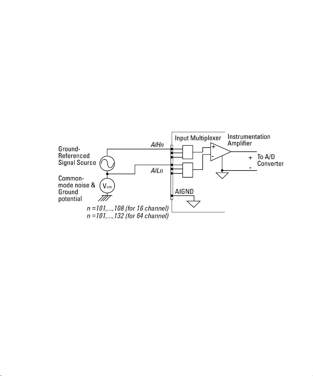
• Non- Referenced Single- Ended (NRSE) Mode
In NRSE mode, the DAQ device does not provide the
grounding point. The ground reference point is provided
by the external analog input signal. You can connect the
signals in NRSE mode to measure ground- referenced
signal sources, which are connected to the same
grounding point. The following figure illustrates the
connection. The signal local ground reference is connected
to the negative input of the instrumentation Amplifier
(AI_SENSE pin on connector1). Hence, any potential
difference of the common mode ground between signal
ground and the signal ground on DAQ board will be
rejected by the instrumentation amplifier.
Figure 2-2 Ground-referenced sources and NRSE input connections
U2300A Series DAQ Service Guide 19
Page 28
2 Calibration
Differential Input Mode
The differential input mode provides two inputs that respond
to the difference of the signal voltage. The analog input of
the U2300A series DAQ has its own reference ground or
signal return path. The differential mode can be used for the
common- mode noise rejection if the signal source is
ground- referenced. The following figure shows the
connection of ground- referenced signal sources under
differential input mode.
Figure 2-3 Ground-referenced source and differential input mode
20 U2300A Series DAQ Service Guide
Page 29
Calibration 2
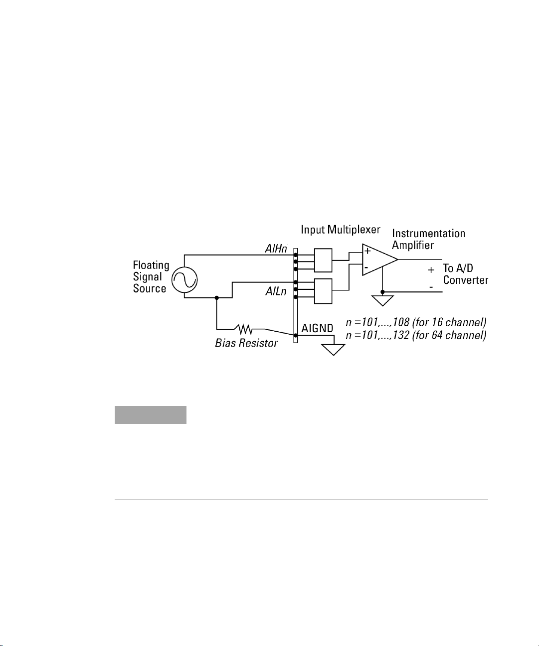
The following figure illustrates the connection of a floating
signal source to the U2300A series DAQ in differential input
mode. For floating signal sources, additional resistor is
needed at each channel to provide a bias return path. The
resistor value is equivalent to about 100 times the source
impedance. If the source impedance is less than 100 W, you
can connect the negative polarity of the signal directly to
AI_GND, as well as the negative input of the Instrumentation
Amplifier. The noise couples in differential input mode are
less compared to the single- ended mode.
Figure 2-4 Floating source and differential input
NOTE
U2300A Series DAQ Service Guide 21
• Agilent U2300A series DAQ is designed with high input impedance.
Please ensure that all the connection are connected properly before
acquiring any data. Failing to do so may cause data fluctuation or
erroneous readings.
• Unused pins at multiplexing DAQ inputs can be treated as floating
source with infinite output impedance. Therefore, necessary grounding
system is required in user application system.
Page 30

2 Calibration
Hardware Connection
The connection to verify the analog input readings and
analog outputs are different. To verify the analog input
readings, see “Analog Input Connection” for descriptions on
the way to connect the instruments. To verify the analog
outputs, see “Analog Output Connection” for descriptions on
hardware setup.
Analog Input Connection
The equipments required for analog input connection are the
DAQ device, Fluke calibrator, terminal block, USB mini- B
cable and SCSI cable. Follow the follwing step- by- step
instruction for analog input connection.
1 Connect the DAQ device to a PC with a USB mini- B cable
and connect the DAQ device to a U2901A terminal block
using the U2901A SCSI cable.
NOTE
22 U2300A Series DAQ Service Guide
• Ensure that the PC has the DAQ device’s driver and the Agilent IO
Libraries 14.2 or higher installed. Note that the Agilent Measurement
Manager software comes with the standard purchase of the U2300A
Series DAQ devices.
• If you do not have the DAQ device’s driver and the Agilent IO Libraries
14.2 or higher installed, refer to the Agilent U2300A Series Data
Acquisition Devices and Agilent Measurement Manager Quick Start
Guide, for more information on the installation.
2 Short all the DAQ device’s analog input channels. Refer to
“Connector Pins Configuration” for the pins assignment.
3 Connect the DAQ device’s analog input channels to the
calibrator output.
4 Connect the DAQ device’s analog input ground (AI_GND)
to the calibrator ground. See Figure 2- 1. Note that the
analog inputs shown in the figure uses U2351A as an
example.
Page 31

Calibration 2
DAQ
AI101
...
AI164
AIGND
Calibrator
Output
GND
Figure 2-5 The analog input and calibrator connection
Setup diagram
DAQ
SCSI Cable
Mini-B
USB Cable
Terminal Block
(e.g. AI101 to AI164
Analog Input
for U2351A)
PC
Calibrator
Figure 2-6 The analog input and calibrator connection
U2300A Series DAQ Service Guide 23
Page 32

2 Calibration
Analog Output Connection
The equipments required for analog output connection are
the DAQ device, DMM, terminal block, USB mini- B cable and
SCSI cable. Follow the follwing step- by- step instruction for
analog input connection.
1 Connect the DAQ device to a PC with a USB mini- B cable
and connect the DAQ device to a U2901A terminal block
using the U2901A SCSI cable.
NOTE
• Ensure that the PC has the DAQ device’s driver and the Agilent IO
Libraries 14.2 or higher installed. Note that the Agilent Measurement
Manager software comes with the standard purchase of the U2300A
Series DAQ devices.
• If you do not have the DAQ device’s driver and the Agilent IO Libraries
14.2 or higher installed, refer to the Agilent U2300A Series Data
Acquisition Devices and Agilent Measurement Manager Quick Start
Guide, for more information on the installation.
2 Connect a wire at each pin you would like to test on the
U2901A terminal block. (Refer to “Connector Pins
Configuration” for the pins assignment)
3 Connect the DAQ device’s analog output channel 1
(AO201) to the DMM input.
4 Connect the DAQ device’s analog output ground
(AO_GND) to DMM GND.
5 Repeat steps 3 and 4 for analog output channel 2
(AO202).
24 U2300A Series DAQ Service Guide
Page 33

Calibration 2
DAQ
AO201
AOGND
DMM
Input
GND
Figure 2-7 The analog input and DMM connection
Setup diagram
DAQ
SCSI Cable
Mini-B
USB Cable
Terminal Block
Analog Output
(e.g. AO201 to AO202
for U2351A)
PC DMM
Figure 2-8 The analog output and DMM connection
U2300A Series DAQ Service Guide 25
Page 34

2 Calibration
Self-Calibration
Self- calibration can be operated using the following SCPI
command via Agilent Connection Expert.
CALibration:BEGin
In calibration mode, the command will initiate a voltage
adjustment in sequence for the specified Digital Analog
Converter (DAC) channel. This sequence sets a zero and gain
adjustment constant for each DAC output.
The function of DAQ device will not carry on until the
self- calibration has completed. You can query the status of
the self- calibration performed using the following SCPI
command.
*OPC?
Two ways of performing the self- calibration will be
introduced in this section. The first option is to use the
Agilent Connection Expert to send the SCPI commands and
the second option is to use the Agilent Measurement
Manager application software.
Option 1: Self-calibration with Agilent Connection Expert
WARNING
• Unplug all cables that are connected to the DAQ device before
performing self-calibration.
• Any cables connected to the DAQ device may cause the failure of
the self-calibration process.
1 Power on the DAQ and disconnect all connections from
DAQ device. Warm it up for 30 minutes to ensure that it
is operating at stable condition.
2 Go to Start > All Programs > Agilent IO Libraries Suite > Agilent
Connection Expert to launch the Agilent Connection Expert.
26 U2300A Series DAQ Service Guide
Page 35

Calibration 2
3 Connect the DAQ device to the PC with mini- B type USB
cable. The connected DAQ device will be visible in the
Instrument I/O on this PC panel as illustrated in Figure 2- 5.
4 Select the DAQ device that you wish to send the SCPI
commands to and then click the Interactive IO icon on the
toolbar to launch the Agilent Interactive IO. See Figure
2- 5.
Step 2: Click the Interactive IO icon
Step 1:
Select the instrument
Figure 2-9 Launch the Interactive IO in Agilent Connection Expert
5 The Agilent Interactive IO dialog box will appear as shown in
Figure 2- 6. Click Send & Read to send the “*IDN?” default
command. This instrument’s response should appear in
the Instrument Session History panel.
U2300A Series DAQ Service Guide 27
Page 36

2 Calibration
6 Successful communication between the Agilent Connection
Expert and the connected hardware will be shown in the
Instrument Session History panel. The users may now send
other SCPI commands to the instrument.
Figure 2-10 Interactive IO dialog box
7 Ensure that the DAQ device has been warmed up for 30
minutes. Send the SCPI commands “*RST” and “*CLS” to
clear the register in DAQ device.
8 Send “CAL:BEG” to start the self- calibration process. This
process may take a few minutes to complete.
9 Send “*OPC?” to check the operation complete status.
10 If “*OPC?” return 1, send “SYST:ERR?” to check if any
system error has occurred during the self- calibration
process. If there is no system error, the self- calibration
process is done. Otherwise, the self- calibration process is
failed.
28 U2300A Series DAQ Service Guide
Page 37
Calibration 2
Option 2: Self-calibration with Agilent Measurement Manager
WARNING
• Unplug all cables that are connected to the DAQ device before
performing self-calibration.
• Any cables connected to the DAQ device may cause the failure of
the self-calibration process.
1 Power on the DAQ device and disconnect all connections
from it. Warm it up for 30 minutes to ensure that it is
operating at stable condition.
2 Connect the DAQ device to the PC with mini- B type USB
cable. Launch the Agilent Measurement Manager and
select the DAQ device you wish to do the self-calibration
process.
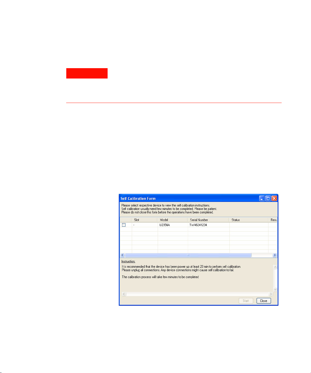
3 Go to Tools and select Self Calibration.
4 The Self Calibration Form dialog box will appear as shown
below.
Figure 2-11 Self Calibration Form dialog box in Agilent Measurement
Manager
U2300A Series DAQ Service Guide 29
Page 38

2 Calibration
5 Select the instrument that you would like to perform
self- calibration and the Start button will be enabled. Click
Start to proceed. See Figure 2- 8.
6 The calibration process will take a few minutes to be
completed. Once done, the status and results of the
process will be displayed as shown in Figure 2- 9.
Figure 2-12 Self Calibration Form dialog box in Agilent Measurement
Manager with a device being selected
30 U2300A Series DAQ Service Guide
Page 39

Calibration 2
Figure 2-13 Self Calibration Form dialog box in Agilent Measurement Ma-
naer showing the status and resultof the self-calibration process
U2300A Series DAQ Service Guide 31
Page 40

2 Calibration
Adjustment Procedures
DAQ on- board 5 V calibration
If in the performance verification procedure is not accurate,
adjustment procedure is required. The following flowchart
shows the steps for 5 V calibration.
Step 1:
Open the DAQ device metal casing.
Power on DAQ device and warm up for 30 minutes.
Connect the DMM to U37 on the daughter board.
Step 2: 5 V calibration
Connect the DAQ device to the computer with USB cable.
Monitor the DMM readings.
Tune the 5 V until you get the voltage in between 4.9999 to 5.0001 V.
Send “CAL:VREF:TUNE MINUS” (to decrease voltage),
Send “CAL:VREF:TUNE PLUS” (to increase voltage),
Send “CAL:VREF” (to save to EPROM)
Step 3:
After save to EPROM,
power cycle the unit.
Step 4:
Reconfirm the 5 V
reading.
Figure 2-14 The flowchart showing the steps for 5 V calibration
32 U2300A Series DAQ Service Guide
Page 41

Calibration 2
Tab l e 2 - 3 Step-by-step descriptions for Figure 2-10
Step Descriptions
Step 1 Before power on the DAQ device, open the DAQ device’s metal casing. Refer to “Dismantle Procedures” for
more information to disassemble the unit. Then, power on the DAQ device and warm it up for approximately 30
minutes. Connect the DMM to U37 on the daughter board. The following images shows the location of U37 and
the way to connect it.
U37
Step 2 Ensure that the DAQ device’s driver is installed in the computer before connecting it to the computer. The driver
can be obtained from the Agilent USB Modular Instrument U2300A & U2700A Series Product Reference
CD-ROM. Measure the voltage difference at U37 with the DMM. If the measured voltage is more than 5 V, send
the command “
CAL:VREF:TUNE MINUS” to decrease the voltage, otherwise if the measured
voltage is less than 5 V, send the command “CAL:VREF:TUNE PLUS” to increase the voltage.
Tune the voltage until the measured voltage is in the range of 4.9999 V and 5.0001 V. When the
tuning process is done, send “CAL:VREF” to save it in the EPROM.
Step 3 Power cycle the DAQ device by turning on and off the DAQ device.
Step 4 Measure the voltage at U37 again to ensure the measured voltage is in the range of 4.9999V to 5.0001 V. If there
is any problem occurs, the DMM will not measure the voltage in the specified range.
Proceed to self calibration procedure.
U2300A Series DAQ Service Guide 33
Page 42

2 Calibration
Performance Verification Procedure
Prior to calibrate the instrument, check the performance of
the instrument to see if any adjustment is required, “Step 2:
DAQ configuration and verification test”.
This is to ensure that the DAQ device gives accurate
readings or outputs. The performance verification procedure
for analog input and analog output are automated and are
verify using the Automated Calibration software.
The performance verification procedure involve two steps:
Step 1: DAQ self- calibration
Step 2: DAQ configuration and verification test
Analog Output
34 U2300A Series DAQ Service Guide
Page 43

Calibration 2
Step 1: DAQ self- calibration
Step 1:
Power on DAQ device and disconnect all connections from DAQ.
Warm up for 30 minutes.
Step 2: Reset DAQ
Send “*RST”
Step 3: Clear DAQ
Send “*CLS”
Step 4:
Wait: 1 second
Step 5: Start self-calibration
Send “CAL:BEG”
Wait: 60 seconds
Step 6: Check operation complete status
Send “*OPC?”
No
U2300A Series DAQ Service Guide 35
OPC status = 1?
Ye s
Step 7: Read system error
“SYST:ERR?”
System error?
No
Calibration DONE!
Ye s
Calibration FAIL!
Page 44

2 Calibration
Step 2: DAQ configuration and verification test
Step 1:
Step 1:
Power on DAQ device and connect the calibrator to DAQ. Warm up for
Power on DAQ device and connect the calibrator to DAQ. Warm up for
30 minutes.
30 minutes.
Step 2: DAQ configuration
Step 2: DAQ configuration
Send “ROUT:SCAN(@Channel))”, Send “ROUT:CHAN:RANG
Send “ROUT:SCAN(@Channel)”, Send “ROUT:CHAN:RANG
Range,(Channel))”, Send “ROUT:CHAN:RANG Range,((@Channel))”,
Range,(@Channel)”, Send “ROUT:CHAN:POL Polarity,(@Channel)”,
Send “ACQ:SRAT MaxSamplingRate”
Send “ACQ:SRAT MaxSamplingRate”
Step 3: Calibrator
Step 3: Calibrator
Source the desired test voltage to DAQ
Source the desired test voltage to DAQ
Step 4: DAQ data acquisition
Send “ACQ:POIN 100”, Send “DIG”
Wait: 0.2 second
Step 5: Check waveform complete status
Send “WAV:COMP?”
No
Step 6: DAQ fetch data
Send “WAV:DATA?” Read data as int 16 array
Step 7: Data conversion
Convert the data into voltage and get the average value for 100
points (please see Data conversion section for the formula)
Repeat steps above for all channels, polarities and ranges The
test points are shown as table
36 U2300A Series DAQ Service Guide
WAV complete status = YES?
Ye s
Compare the reading with the test specification
Page 45

Calibration 2
NOTE
Byte ordering must use LSB first.
Analog Output
Step 1:
Power on DAQ device and conenct the DMM
to DAQ. Warm up for 30 minutes
Step 2: DAQ configuration
Send “SOUR:VOLT:POL Polarity,(@Channel)”,
Send “SOUR:VOLT”RSRC INT,(@Channel)”,
Send “SOUR:VOLT Voltage,(@Channel)”
Step 3: DMM
Measure the output voltage of DAQ
Repeat steps above for all channels and
polarities. The test points are shown as table
Compare the reading with
the test specification
U2300A Series DAQ Service Guide 37
Page 46

2 Calibration
A/D Data Conversion
A/D data conversion converts analog voltage into digital
information. The following section illustrates the format of
acquired raw data for the A/D conversion.
Below is the illustrated example of the acquired raw data
scan list for CH 101, CH 102, and CH 103.
#800000200 <byte> <byte> <byte> <byte> <byte> <byte> <byte> <byte> ...
Data length indicator, The
next 8 bytes (0000 0200)
specifying the actual data
length only, not actual data.
Data length (200 bytes long)
1st data
LSB
1st data
MSB
CH 101 CH 102 CH 103 CH 101 ...
1st data
LSB
1st data
MSB
1st data
LSB
1st data
MSB
2nd data
LSB
16-bit Data Format
LSB MSB
DDDD DDDD DDDD DDDD
2nd data
MSB
...
12-bit Data Format
LSB MSB
DDDD XXXX DDDD DDDD
D - Data bits
X - Unused bits
Raw data conversion
To convert the data into an actual float number, we need
the voltage range and polarity information. Below are the
calculations on the raw data conversion for both bipolar and
unipolar.
To perform a sample calculation of the conversion, take
the U2356A as an example. The resolution of U2356A is
16 bits and the range is taken as 10 V. The Int16b value
calculated using conversion algorithm is 12768.
38 U2300A Series DAQ Service Guide
Page 47

Calibration 2
Hence, the 16 bits binary read back calculation will be as
follows.
LSB MSB
<11100000> <00110001>
= 12768
NOTE
NOTE
The raw data provided by U2300A series DAQ devices is in the byte order
of LSB first.
Bipolar:
2 Int16 value×
⎛⎞
Converted value
Example of converted value
--------------------------------------
⎝⎠
resolution
2
⎛⎞
⎝⎠
Range×=
2 12768×
------------------------
16
2
10× 3.896 V==
Unipolar:
Int16 value
⎛⎞
Converted value
----------------------------
⎝⎠
resolution
2
Example of converted value
The converted value is of float type. As such, you may need to type cast
the Int16 value to float in your programming environment.
0.5+
Range×=
12768
⎛⎞
---------------
⎝⎠
2
16
0.5+
10× 6.948 V==
To perform a sample calculation of the conversion, take
the U2331A as an example. The resolution of U2331A is
12 bits and the range is taken as 10 V. The Int12b value
calculated using conversion algorithm is 12768.
LSB MSB
<11100000> <00110001>
= 12768
U2300A Series DAQ Service Guide 39
Page 48

2 Calibration
There are unused bits in the 12- bit data format.
Therefore, there is a need to perform a 4- bit right shift
operation. Hence, the 12 bits binary read back calculation
will be as follows.
LSB MSB
<00011110> <00000011>
= 798
NOTE
NOTE
The raw data provided by U2300A series DAQ devices is in the byte order
of LSB first.
Bipolar:
2 Int16 value×
⎛⎞
Converted value
Example of converted value
--------------------------------------
⎝⎠
resolution
2
Range×=
2798×
⎛⎞
------------------
⎝⎠
12
2
10× 3.896 V==
Unipolar:
Int16 value
⎛⎞
Converted value
----------------------------
⎝⎠
resolution
2
Example of converted value
• The converted value is of float type. As such, you may need to type cast
the Int12 value to float in your programming environment.
0.5+
Range×=
798
⎛⎞
---------
0.5+
⎝⎠
12
2
10× 6.948 V==
• For the U2331A, there is a need to perform a 4-bit right shift operation.
This is because it is equipped with 12-bit ADC, and the last 4 bits are
truncated.
40 U2300A Series DAQ Service Guide
Page 49

Agilent U2300A Series USB Multifunction DAQ
Service Guide
3
Dismantle Procedures
General Disassemble 42
Mechanical Disassemble 42
Replacement Parts 46
This chapter describes the step- by- step disassemble
procedures and list the available replacement parts for
U2300A Series DAQ devices,
Agilent Technologies
41
Page 50

3 Dismantle Procedures
General Disassemble
NOTE
This chapter provides the step- by- step guides on how to
dismantle the module and install the replacement assembly. To
assemble back the module, follow the instructions in reverse
order.
The parts shown in the following figures are representative and
may look different than what you have in your module.
The removable assemblies include:
• Plastic casing
• Metal casing
• Rear metal casing
• Front metal casing, which is attached to the carrier board
and measurement board
Mechanical Disassemble
Follow the instructions in this section for the instrument
disassemble process.
Step 1: Pull the bumper out to remove the plastic casing.
Plastic casing
42 U2300A Series DAQ Service Guide
Page 51

Dismantle Procedures 3
Step 2: Flip the plastic casing open.
Step 3: Slide the metal casing out of the plastic casing.
Metal casing
U2300A Series DAQ Service Guide 43
Page 52

3 Dismantle Procedures
Front metal piece
Step 4: Unscrew all the following indicated screws from metal
casing.
Step 5: Gently pull the front metal piece out, which is attached to
the carrier and measurement boards.
Step 6: Unscrew all the following indicated screws from the
metal casing and remove the rear metal piece.
Rear metal casing
44 U2300A Series DAQ Service Guide
Page 53

Metal casing
Rear metal casing
Carrier board and
measurement board
Dismantle Procedures 3
Disassembled parts:
Front
metal casing
U2300A Series DAQ Service Guide 45
Page 54

3 Dismantle Procedures
Replacement Parts
This section provides the information of orderable replacement
parts for U2300A Series DAQ devices. The parts availabled for
replacement are listed in the table below with the reference
part numbers and the respective part names.
You can order the replacement parts from Agilent using the part
number provided in the table below. To order replacement parts
from Agilent, do the following:
1 Identify the Agilent part number of the required parts as
shown in the replacement parts list.
2 Contact your nearest Agilent Sales Office or Service Center.
3 Provide the instrument model number and serial number.
Tab l e 3 - 4 Replacement parts list
Part Number Part Name
U2351-60002 Metal Casing
5190-0013 Plastic Cover
U2351-00201 Rear Metal Piece
U2351-61201 L-shape Mount
46 U2300A Series DAQ Service Guide
Page 55

Agilent U2300A Series USB Multifunction DAQ
Service Guide
4
Troubleshooting and Self-Test
Procedures
Troubleshooting 48
Self-Test Procedures 49
This chapter provides the information on general troubleshooting and
self-test procedures.
Agilent Technologies
47
Page 56

4 Troubleshooting and Self-Test Procedures
Troubleshooting
This section provides suggestions for solving general problems that
you may encounter with the instrument. It guides you on what to
check in the following situations:
1. Power Indicator LED is not lit
Verify that the ac power cord is connected to the power inlet in
the DAQ device.
2. Power Indicator LED is lit but the AO/ AI Indicator LED is not lit
Verify that the USB cable is connected to the PC and the USB
inlet in the DAQ device.
3. Power Indicator LED is lit and AO/ AI Indicator LED is lit
Verify if the SCPI commands are correct with “SYSTem:ERRor?”
command.
Refer to U2300A Series USB Multifunction Programming Guide for
SCPI error messages.
NOTE
48 U2300A Series DAQ Service Guide
If there are no response from the instrument, contact the nearest Agilent
Service Center to obtain further assistance.
Page 57

Self-Test Procedures
Troubleshooting and Self-Test Procedures 4
WARNING
4 Go to Start > All Programs > Agilent IO Libraries Suite > Agilent
5 Go to Start > All Programs > Agilent T&M Toolkit > Agilent Interactive IO
6 Send the SCPI command “*TST?” to the instrument to start
7 The command will return either "+0" to indicate all tests passes
8 If the command returns "+1" , apply SCPI command
NOTE
Do not connect any cables and terminal block prior to performing
self-test procedures.
Connection Expert to launch the Agilent Connection Expert.
to launch the Interactive I/O dialog box.
perform the self- test of the instrument.
or "+1" to indicate one or more tests failed.
“SYSTem:ERRor?” to enquire the error message.
Refer to Agilent U2300A Series USB Multifunction Data Acquisition
Programming Guide for SCPI error messages.
U2300A Series DAQ Service Guide 49
Page 58

4 Troubleshooting and Self-Test Procedures
50 U2300A Series DAQ Service Guide
Page 59

Agilent U2300A Series USB Multifunction DAQ
Service Guide
A
Connector Pins Configuration
Pins Configuration for U2331A, U2355A and U2356A 52
Pins Configuration for U2351A, U2352A, U2353A and U2354A 53
This appendix attached the pins configuration for all the
U2300A Series DAQ devices.
Agilent Technologies
51
Page 60

A Connector Pins Configuration
Pins Configuration for U2331A, U2355A and U2356A
The U2300A Series DAQ is equipped with 68–pin very high
density cable interconnect (VHDCI) type connectors.
Figure A-1 Pins Configuration of Connector 1 for
U2331A, U2355A, U2356A
NOTE
52 U2300A Series DAQ Service Guide
(AIH101..132) and (AIL101..132) are for differential mode connection pair.
Figure A-2 Pins Configuration of Connector 2
for U2331A, U2355A, U2356A
Page 61

Connector Pins Configuration A
Pins Configuration for U2351A, U2352A, U2353A and U2354A
Figure A-3 Pins Configuration for U2352A,
U2354A
NOTE
U2300A Series DAQ Service Guide 53
(AIH101..108) and (AIL101..108) are for differential mode connection pair.
Figure A-4 Pins Configuration for U2351A,
U2353A
Page 62

A Connector Pins Configuration
Tab l e A- 5 68-pin VHDCI connector pins descriptions
Signal Name Direction Reference
Ground
AI_GND N/A N/A Analog input (AI) ground. All three ground
For 16 Channels:
AI<101..116>
For 64 Channels:
AI<101..164>
AI_SENSE Input AI_GND Analog input sense. The reference pin for any
EXTA_TRIG Input AI_GND External AI analog trigger
AO201 Output AO_GND Analog output channel 1
AO202 Output AO_GND Analog output channel 2
AO_EXT_REF Input AO_GND External reference for AO channels
AO_GND N/A N/A Analog ground for AO
EXTD_AO_TRIG Input D_GND External AO waveform trigger
EXTD_AI_TRIG Input D_GND External AI digital trigger
RESERVED Output N/A Reserved pins. Do not connect them to any signal.
COUNT<301,302>_CLK Input D_GND Source of counter <301,302>
COUNT<301,302>_GATE Input D_GND Gate of counter <301,302>
COUNT<301,302>_OUT Input D_GND Output of counter <301,302>
COUNT<301,302>_UPDOWN Input D_GND Up/Down of counter <301,302>
EXT_TIMEBASE Input D_GND External Timebase
D_GND N/A N/A Digital ground
DIO501<7,0> PIO D_GND Programmable DIO of Channel 501
DIO502<7,0> PIO D_GND Programmable DIO of Channel 502
DIO503<4,0> PIO D_GND Programmable DIO of Channel 503
DIO504<4,0> PIO D_GND Programmable DIO of Channel 504
Input AI_GND U2351A/U2352A/U2353A/U2354A
Description
references (AI_GND, AO_GND, and D_GND) are
connected together on board.
Analog input channels 101~116. Each channel pair, AI<i,
i+8>(i = 101..108), can be configured either as two
single-ended inputs or one differential input (marked as
AIH<101..108> and AIL<101..108>).
U2331A/U2356A/U2355A
Analog input channels 101~164). Each channel pair, AI<i,
i+32> (i = 101..132), is configured either as two
single-ended inputs or one differential input (marked as
AIH<101..132> and AIL<101..132>)
AI<101..116> or AI<101..164> channels in NRSE input
configuration.
54 U2300A Series DAQ Service Guide
Page 63

Connector Pins Configuration A
U2300A Series DAQ Service Guide 55
Page 64

A Connector Pins Configuration
56 U2300A Series DAQ Service Guide
Page 65

Agilent U2300A Series USB Multifunction DAQ
Service Guide
B
Test Limits
Analog Input 58
Analog Output 62
This appendix provides the test limits for analog input and analog output
when performing the verification procedure.
Agilent Technologies
57
Page 66

BTest Limits
Setting Range (V) Test Point (V) Te st L im i t ( V ) Tes t Re s ul t
Polarity Min Max Location Val ue Lower Upper Reading
0.001 BIP –10 10 Center FS 0.00000 –0.00100 0.00100 Offset = DAQ reading – Calibrator source voltage
0.002 BIP –10 10 Positive FS 9.98779 9.98579 9.98979 DAQ reading – Offset
0.002 BIP –10 10 Negative FS –9.98779 –9.98979 –9.98579 DAQ reading – Offset
0.001 BIP –5 5 Center FS 0.00000 –0.00100 0.00100 Offset = DAQ reading – Calibrator source voltage
0.002 BIP –5 5 Positive FS 4.99390 4.99190 4.99590 DAQ reading – Offset
0.002 BIP –5 5 Negative FS –4.99390 –4.99590 –4.99190 DAQ reading – Offset
Offset/
Analog Input
Analog Input
Gain Error (V)
U2351A, U2352A, U2353A, U2354A:
0.001 BIP –2.5 2.5 Center FS 0.00000 –0.00100 0.00100 Offset = DAQ reading – Calibrator source voltage
0.001 BIP –1.25 1.25 Center FS 0.00000 –0.00100 0.00100 Offset = DAQ reading – Calibrator source voltage
0.0015 BIP –2.5 2.5 Positive FS 2.49695 2.49545 2.49845 DAQ reading – Offset
0.0015 BIP –2.5 2.5 Negative FS –2.49695 –2.49845 –2.49545 DAQ reading – Offset
0.0015 BIP –1.25 1.25 Positive FS 1.24847 1.24697 1.24997 DAQ reading – Offset
0.0015 BIP –1.25 1.25 Negative FS –1.24847 –1.24997 –1.24697 DAQ reading – Offset
0.002 UNIP 0 10 Positive FS 9.99390 9.99190 9.99590 DAQ reading – Offset
0.002 UNIP 0 10 Negative FS 0.00610 0.00410 0.00810 DAQ reading – Offset
0.002 UNIP 0 5 Positive FS 4.99695 4.99495 4.99895 DAQ reading – Offset
0.002 UNIP 0 5 Negative FS 0.00305 0.00105 0.00505 DAQ reading – Offset
0.001 UNIP 0 2.5 Center FS 1.25000 1.24900 1.25100 Offset = DAQ reading – Calibrator source voltage
0.001 UNIP 0 2.5 Positive FS 2.49847 2.49747 2.49947 DAQ reading – Offset
0.001 UNIP 0 2.5 Negative FS 0.00153 0.00053 0.00253 DAQ reading – Offset
0.001 UNIP 0 1.25 Center FS 0.62500 0.62400 0.62600 Offset = DAQ reading – Calibrator source voltage
0.001 UNIP 0 1.25 Positive FS 1.24924 1.24824 1.25024 DAQ reading – Offset
0.0015 UNIP 0 10 Center FS 5.00000 4.99850 5.00150 Offset = DAQ reading – Calibrator source voltage
0.0015 UNIP 0 5 Center FS 2.50000 2.49850 2.50150 Offset = DAQ reading – Calibrator source voltage
0.001 UNIP 0 1.25 Negative FS 0.00076 –0.00024 0.00176 DAQ reading – Offset
58 U2300A Series DAQ Service Guide
Page 67

Test Limits B
Setting Range (V) Test Point (V) Te st L im i t ( V ) Tes t Re s ul t
Polarity Min Max Location Val ue Lower Upper Reading
0.001 BIP –10 10 Center FS 0.00000 –0.00100 0.00100 Offset = DAQ reading – Calibrator source voltage
0.002 BIP –10 10 Positive FS 9.98779 9.98579 9.98979 DAQ reading – Offset
0.002 BIP –10 10 Negative FS –9.98779 –9.98979 –9.98579 DAQ reading – Offset
0.001 BIP –5 5 Center FS 0.00000 –0.00100 0.00100 Offset = DAQ reading – Calibrator source voltage
0.002 BIP –5 5 Positive FS 4.99390 4.99190 4.99590 DAQ reading – Offset
0.002 BIP –5 5 Negative FS –4.99390 –4.99590 –4.99190 DAQ reading – Offset
Analog Input
U2355A, U2356A:
Offset/
Gain Error (V)
0.001 BIP –2.5 2.5 Center FS 0.00000 –0.00100 0.00100 Offset = DAQ reading – Calibrator source voltage
0.001 BIP –1.25 1.25 Center FS 0.00000 –0.00100 0.00100 Offset = DAQ reading – Calibrator source voltage
0.0015 BIP –2.5 2.5 Positive FS 2.49695 2.49545 2.49845 DAQ reading – Offset
0.0015 BIP –2.5 2.5 Negative FS –2.49695 –2.49845 –2.49545 DAQ reading – Offset
0.0015 BIP –1.25 1.25 Positive FS 1.24847 1.24697 1.24997 DAQ reading – Offset
0.001 UNIP 0 10 Center FS 5.00000 4.99900 5.00100 Offset = DAQ reading – Calibrator source voltage
0.0015 BIP –1.25 1.25 Negative FS –1.24847 –1.24997 –1.24697 DAQ reading – Offset
0.001 UNIP 0 5 Center FS 2.50000 2.49900 2.50100 Offset = DAQ reading – Calibrator source voltage
0.0015 UNIP 0 10 Positive FS 9.99390 9.99240 9.99540 DAQ reading – Offset
0.0015 UNIP 0 10 Negative FS 0.00610 0.00460 0.00760 DAQ reading – Offset
0.001 UNIP 0 2.5 Center FS 1.25000 1.24900 1.25100 Offset = DAQ reading – Calibrator source voltage
0.001 UNIP 0 2.5 Positive FS 2.49847 2.49747 2.49947 DAQ reading – Offset
0.001 UNIP 0 2.5 Negative FS 0.00153 0.00053 0.00253 DAQ reading – Offset
0.001 UNIP 0 1.25 Center FS 0.62500 0.62400 0.62600 Offset = DAQ reading – Calibrator source voltage
0.001 UNIP 0 1.25 Positive FS 1.24924 1.24824 1.25024 DAQ reading – Offset
0.0015 UNIP 0 5 Positive FS 4.99695 4.99545 4.99845 DAQ reading – Offset
0.0015 UNIP 0 5 Negative FS 0.00305 0.00155 0.00455 DAQ reading – Offset
0.001 UNIP 0 1.25 Negative FS 0.00076 –0.00024 0.00176 DAQ reading – Offset
U2300A Series DAQ Service Guide 59
Page 68

BTest Limits
Setting Range (V) Test Point (V) Te st L im i t ( V ) Tes t Re s ul t
Polarity Min Max Location Val ue Lower Upper Reading
0.002 BIP –10 10 Center FS 0.00000 -0.00200 0.00200 Offset = DAQ reading – Calibrator source voltage
0.006 BIP –10 10 Positive FS 9.80469 9.79869 9.81069 DAQ reading – Offset
0.006 BIP –10 10 Negative FS –9.80469 –9.81069 –9.79869 DAQ reading – Offset
0.004 BIP –5 5 Positive FS 4.90234 4.89834 4.90634 DAQ reading – Offset
0.004 BIP –5 5 Negative FS –4.90234 –4.90634 –4.89834 DAQ reading – Offset
0.002 BIP –2.5 2.5 Positive FS 2.45117 2.44917 2.45317 DAQ reading – Offset
0.002 BIP –2.5 2.5 Negative FS –2.45117 –2.45317 –2.44917 DAQ reading – Offset
Analog Input
U2331A:
Offset/
Gain Error (V)
0.0015 BIP –5 5 Center FS 0.00000 –0.00150 0.00150 Offset = DAQ reading – Calibrator source voltage
0.0015 BIP –2.5 2.5 Center FS 0.00000 –0.00150 0.00150 Offset = DAQ reading – Calibrator source voltage
0.001 BIP –1.25 1.25 Center FS 0.00000 –0.00100 0.00100 Offset = DAQ reading – Calibrator source voltage
0.001 BIP –1 1 Center FS 0.00000 –0.00100 0.00100 Offset = DAQ reading – Calibrator source voltage
0.001 BIP –1 1 Positive FS 0.98047 0.97947 0.98147 DAQ reading – Offset
0.001 BIP –1 1 Negative FS –0.98047 –0.98147 –0.97947 DAQ reading – Offset
0.001 BIP –0.5 0.5 Center FS 0.00000 –0.00100 0.00100 Offset = DAQ reading – Calibrator source voltage
0.001 BIP –0.5 0.5 Positive FS 0.49023 0.48923 0.49123 DAQ reading – Offset
0.001 BIP –0.5 0.5 Negative FS –0.49023 –0.49123 –0.48923 DAQ reading – Offset
0.001 BIP –0.25 0.25 Center FS 0.00000 –0.00100 0.00100 Offset = DAQ reading – Calibrator source voltage
0.001 BIP –0.25 0.25 Positive FS 0.24512 0.24412 0.24612 DAQ reading – Offset
0.001 BIP –0.25 0.25 Negative FS –0.24512 –0.24612 –0.24412 DAQ reading – Offset
0.001 BIP –0.2 0.2 Center FS 0.00000 –0.00100 0.00100 Offset = DAQ reading – Calibrator source voltage
0.001 BIP –0.2 0.2 Positive FS 0.19609 0.19509 0.19709 DAQ reading – Offset
0.001 BIP –0.2 0.2 Negative FS –0.19609 –0.19709 –0.19509 DAQ reading – Offset
0.001 BIP –0.05 0.05 Center FS 0.00000 –0.00100 0.00100 Offset = DAQ reading – Calibrator source voltage
0.001 BIP –0.05 0.05 Positive FS 0.04902 0.04802 0.05002 DAQ reading – Offset
0.0015 BIP –1.25 1.25 Positive FS 1.22559 1.22409 1.22709 DAQ reading – Offset
0.0015 BIP –1.25 1.25 Negative FS –1.22559 –1.22709 –1.22409 DAQ reading – Offset
0.001 BIP –0.05 0.05 Negative FS –0.04902 –0.05002 –0.04802 DAQ reading – Offset
60 U2300A Series DAQ Service Guide
Page 69

Test Limits B
Setting Range (V) Test Point (V) Tes t Li m it ( V) Test Result
Polarity Min Max Location Val ue Lower Upper Reading
0.004 UNIP 0 10 Positive FS 9.90234 9.89834 9.90634 DAQ reading – Offset
0.004 UNIP 0 10 Negative FS 0.09766 0.09366 0.10166 DAQ reading – Offset
0.002 UNIP 0 5 Positive FS 4.95117 4.94917 4.95317 DAQ reading – Offset
0.002 UNIP 0 5 Negative FS 0.04883 0.04683 0.05083 DAQ reading – Offset
Analog Input
U2331A:
0.0015 UNIP 0 10 Center FS 5.00000 4.99850 5.00150 Offset = DAQ reading – Calibrator source voltage
Offset/
Gain Error (V)
0.0015 UNIP 0 5 Center FS 2.50000 2.49850 2.50150 Offset = DAQ reading – Calibrator source voltage
0.001 UNIP 0 4 Center FS 2.00000 1.99850 2.00150 Offset = DAQ reading – Calibrator source voltage
0.001 UNIP 0 2.5 Center FS 1.25000 1.24900 1.25100 Offset = DAQ reading – Calibrator source voltage
0.001 UNIP 0 2.5 Positive FS 2.47559 2.47409 2.47709 DAQ reading – Offset
0.001 UNIP 0 2.5 Negative FS 0.02441 0.02291 0.02591 DAQ reading – Offset
0.001 UNIP 0 2 Center FS 1.0000 0.99900 1.00100 Offset = DAQ reading – Calibrator source voltage
0.001 UNIP 0 2 Positive FS 1.98047 1.97947 1.98147 DAQ reading – Offset
0.001 UNIP 0 2 Negative FS 0.01953 0.01853 0.02053 DAQ reading – Offset
0.001 UNIP 0 1 Center FS 0.50000 0.49900 0.50100 Offset = DAQ reading – Calibrator source voltage
0.001 UNIP 0 1 Positive FS 0.99023 0.98923 0.99123 DAQ reading – Offset
0.001 UNIP 0 1 Negative FS 0.00977 0.00877 0.01077 DAQ reading – Offset
0.001 UNIP 0 0.5 Center FS 0.25000 0.24900 0.25100 Offset = DAQ reading – Calibrator source voltage
0.001 UNIP 0 0.5 Positive FS 0.49512 0.49412 0.49612 DAQ reading – Offset
0.001 UNIP 0 0.5 Negative FS 0.00488 0.00388 0.00588 DAQ reading – Offset
0.001 UNIP 0 0.4 Center FS 0.20000 0.19900 0.20100 Offset = DAQ reading – Calibrator source voltage
0.001 UNIP 0 0.4 Positive FS 0.39609 0.39509 0.39709 DAQ reading – Offset
0.001 UNIP 0 0.4 Negative FS 0.00391 0.00291 0.00491 DAQ reading – Offset
0.001 UNIP 0 0.1 Center FS 0.05000 0.04900 0.05100 Offset = DAQ reading – Calibrator source voltage
0.001 UNIP 0 0.1 Positive FS 0.09902 0.09802 0.10002 DAQ reading – Offset
0.0015 UNIP 0 4 Positive FS 3.96094 3.95894 3.96294 DAQ reading – Offset
0.0015 UNIP 0 4 Negative FS 0.03906 0.03706 0.04106 DAQ reading – Offset
0.001 UNIP 0 0.1 Negative FS 0.00098 –0.00002 0.00198 DAQ reading – Offset
U2300A Series DAQ Service Guide 61
Page 70

BTest Limits
Setting Range (V) Test Point (V) Tes t L im i t ( V ) Tes t R esu l t
Polarity Min Max Location Val ue Lower Upper Reading
0.001 BIP –10 10 0 0.0000 –0.0010 0.0010 Offset = DMM reading – DAQ source voltage
Offset/
Analog Output
Analog Output
Gain Error (V)
U2351A, U2353A:
0.004 BIP –10 10 Positive FS 9.9997 9.9957 10.0037 DMM reading – Offset
0.004 BIP –10 10 Negative FS –10.0000 –10.0040 –9.9960 DMM reading – Offset
0.001 UNIP 0 10 0 0.0000 –0.0010 0.0010 Offset = DMM reading – DAQ source voltage
0.002 UNIP 0 10 Positive FS 9.9998 9.9978 10.0018 DMM reading – Offset
Setting Range (V) Test Point (V) Tes t L im i t ( V ) Tes t R esu l t
Polarity Min Max Location Val ue Lower Upper Reading
Offset/
Analog Output
Gain Error (V)
U2355A, U2356A:
0.001 BIP –10 10 0 0.0000 –0.0010 0.0010 Offset = DMM reading – DAQ source voltage
0.004 BIP –10 10 Positive FS 9.9951 9.9911 9.9991 DMM reading – Offset
0.004 BIP –10 10 Negative FS –10.0000 –10.0040 –9.9960 DMM reading – Offset
0.001 UNIP 0 10 0 0.0000 –0.0010 0.0010 Offset = DMM reading – DAQ source voltage
0.002 UNIP 0 10 Positive FS 9.9976 9.9956 9.9996 DMM – Offset
Setting Range (V) Test Point (V) Tes t L im i t ( V ) Tes t R esu l t
Polarity Min Max Location Val ue Lower Upper Reading
Offset/
Analog Output
Gain Error (V)
U2331A:
0.004 BIP –10 10 Positive FS 9.9951 9.9911 9.9991 DMM reading – Offset
0.004 BIP –10 10 Negative FS –10.0000 –10.0040 –9.9960 DMM reading – Offset
0.0015 BIP –10 10 0 0.0000 –0.0015 0.0015 Offset = DMM reading – DAQ source voltage
62 U2300A Series DAQ Service Guide
0.004 UNIP 0 10 Positive FS 9.9976 9.9936 10.0016 DMM reading – Offset
0.0025 UNIP 0 10 0 0.0000 –0.0025 0.0025 Offset = DMM reading – DAQ source voltage
Page 71

www.agilent.com
Contact us
o obtain service, warranty or technical
T
support assistance, contact us at the following
phone numbers:
United States:
(tel) 800 829 4444 (fax) 800 829 4433
Canada:
(tel) 877 894 4414 (fax) 800 746 4866
China:
(tel) 800 810 0189 (fax) 800 820 2816
Europe:
(tel) 31 20 547 2111
Japan:
(tel) (81) 426 56 7832 (fax) (81) 426 56
7840
Korea:
(tel) (080) 769 0800 (fax) (080) 769 0900
Latin America:
(tel) (305) 269 7500
Ta i w a n :
(tel) 0800 047 866 (fax) 0800 286 331
Other Asia Pacific Countries:
(tel) (65) 6375 8100 (fax) (65) 6755 0042
Or visit Agilent worlwide web at:
www.agilent.com/find/assist
Product specifications and descriptions in
this document subject to change without notice.
© Agilent Technologies, Inc. 2007 - 2010
Printed in Malaysia
Second Edition, August 23, 2010
U2351-90203
Agilent Technologies
 Loading...