

Page 1

Agilent U1731C, U1732C,
and U1733C Handheld
LCR Meter
User’s Guide
Agilent Technologies
Page 2

Notices
CAUTION
WARNING
© Agilent Technologies, Inc. 2011
No p art o f this manu al may be re produce d in
any form or by any means (including electronic storage and retrieval or translation
into a foreign language) without prior agreement and written consent from Agilent
Technologies, Inc. as governed by United
States and international copyright laws.
Manual Part Number
U1731-90077
Edition
Second Edition, November 2011
Agilent Technologies, Inc.
5301, Stevens Creek Blvd.
Santa Clara, CA 95051 USA
Warranty
The material contained in this document is
provided “as is,” and is subject to change,
without notice, in future editions. Further,
to the maximum extent permitted by the
applicable law, Agilent disclaims all warranties, either express or implied, with
regard to this manual and any information
contained herein, including but not limited
to the implied warranties of merchantability and fitness for a particular purpose.
Agilent shall not be liable for errors or for
incidental or consequential damages in
connection with the furnishing, use, or
performance of this document or of any
information contained herein. Should Agilent and the user have a separate written
agreement with warranty terms covering
the material in this document that conflict
with these terms, the warranty terms in
the separate agreement shall control.
Technology Licenses
The hardware and or software described in
this document are furnished under a license
and may be used or copied only in accordance with the terms of such license.
Restricted Rights Legend
U.S. Government Restricted Rights. Software and technical data rights granted to
the federal government include only those
rights customarily provided to end user customers. Agilent provides this customary
commercial license in Software and technical data pursuant to FAR 12.211 (Technical
Data) and 12.212 (Computer Software) and,
for the Department of Defense, DFARS
252.227-7015 (Technical Data - Commercial
Items) and DFARS 227.7202-3 (Rights in
Commercial Computer Software or Computer Software Documentation).
Safety Notices
A CAUTION notice denotes a hazard. It calls attention to an operating procedure, practice, or the likes
of that, if not correctly performed
or adhered to, could result in damage to the product or loss of important data. Do not proceed beyond a
CAUTION notice until the indicated
conditions are fully understood and
met.
A WARNING notice denotes a
hazard. It calls attention to an
operating procedure, practice, or
the likes of that, if not correctly
performed or adhered to, could
result in personal injury or death.
Do not proceed beyond a WARNING notice until the indicated
conditions are fully understood
and met.
II U1731C/U1732C/U1733C User’s Guide
Page 3
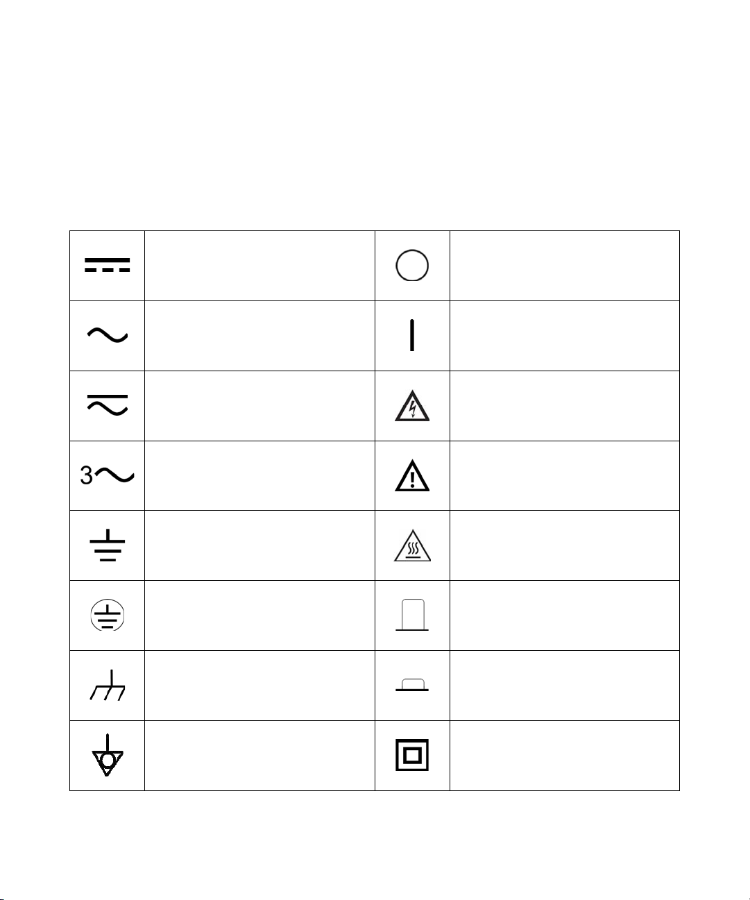
Safety Symbols
Direct current (DC) Off (supply)
Alternating current (AC) On (supply)
Both direct and alternating current Caution, risk of electric shock
The following symbols on the instrument and in the documentation
indicate precautions which must be taken to maintain safe operation of
the instrument.
Three-phase alternating current
Earth (ground) terminal Caution, hot surface
Protective conductor terminal Out position of a bi-stable push control
Frame or chassis terminal In position of a bi-stable push control
Equipotentiality
Caution, risk of danger (refer to this manual
for specific Warning or Caution information)
Equipment protected throughout by
double insulation or reinforced
insulation
U1731C/U1732C/U1733C User’s Guide III
Page 4

Safety Considerations
CAUTION
Read the information below before using this instrument.
The following general safety precautions must be observed during all
phases of operation, service, and repair of this instrument. Failure to
comply with these precautions or with specific warnings elsewhere in this
manual violates safety standards for design, manufacture, and intended
use of the instrument. Agilent Technologies assumes no liability for the
customer’s failure to comply with these requirements.
• Disconnect circuit power and discharge all high-voltage capacitors
before testing.
• When measuring in-circuit components, first de-energize the
circuits before connecting them to the test leads.
• This device is for indoor use at altitudes of up to 2000 m.
• Always use the specified battery type (listed in “Product
Characteristics" on page 74). The power for the meter is supplied
with a single standard 9 V battery. Observe the correct polarity
markings before you insert the battery to ensure proper insertion of
the battery in the meter.
• Line operation is also possible using a 12 V AC to DC adapter. If a
power adapter is selected, please be sure it meets the safety
requirements of a relevant IEC standard.
IV U1731C/U1732C/U1733C User’s Guide
Page 5

WARNING
• Use this meter only as specified in this manual; otherwise, the
protection provided by the meter may be impaired.
• Do not use the meter if it is damaged. Before you use the meter,
inspect the case. Look for cracks or missing plastic. Pay
particular attention to the insulation surrounding the connectors.
• Inspect the test leads for damaged insulation or exposed metal.
Check the test leads for continuity. Replace damaged test leads
before you use the meter.
• Do not operate the meter around explosive gas, vapor, or wet
environments.
• Never use the meter in wet conditions or when there is water on
the surface. If the meter is wet, ensure that the meter is dried only
by trained personnel.
• When servicing the meter, use only the specified replacement
parts.
• When using the probes, keep your fingers behind the finger
guards on the probes.
• Connect the common test lead before you connect the live test
lead. When you disconnect the leads, disconnect the live test lead
first.
U1731C/U1732C/U1733C User’s Guide V
• Remove the test leads from the meter before you open the battery
cover.
• Do not operate the meter with the battery cover or portions of the
cover removed or loosened.
• To avoid false readings, which may lead to possible electric shock
or personal injury, replace the battery as soon as the low battery
indicator appears and flashes.
Page 6

Environmental Conditions
NOTE
This instrument is designed for indoor use and in an area with low
condensation. The table below shows the general environmental
requirements for this instrument.
Environmental conditions Requirements
Operating temperature Full accuracy from –10 °C to 55 °C
Operating humidity Full accuracy up to 80% RH (relative humidity)
Storage temperature –20 °C to 70 °C
Storage humidity 0% to 80% RH non-condensing
Altitude Up to 2000 meters
Pollution degree Pollution degree II
The U1731C/U1732C/U1733C Handheld LCR Meter complies with the following
safety and EMC requirements:
• IEC61010-1:2001/EN61010-1:2001 (Second Edition)
• IEC 61326-1:2005/EN 61326-1:2006
• Canada: ICES/NMB-001:Issue 4, June 2006
• Australia/New Zealand: AS/NZS CISPR11:2004
VI U1731C/U1732C/U1733C User’s Guide
Page 7
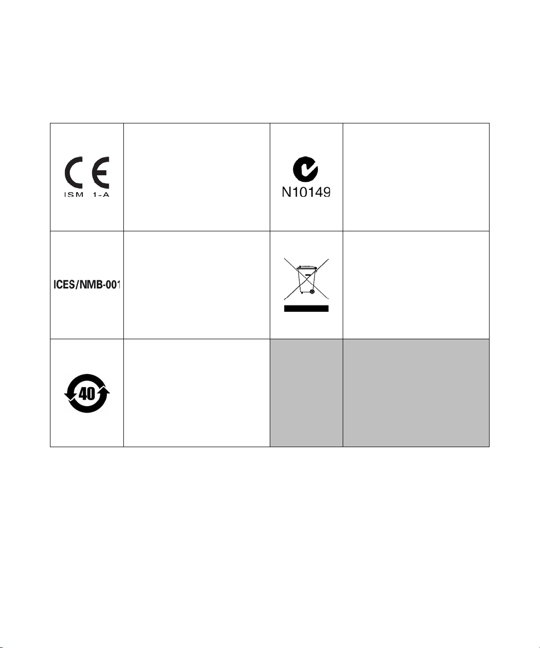
Regulatory Markings
The CE mark is a registered trademark
of the European Community. This CE
mark shows that the product complies
with all the relevant European Legal
Directives.
The C-tick mark is a registered
trademark of the Spectrum
Management Agency of Australia. This
signifies compliance with
the Australia EMC Framework
regulations under the terms of the
Radio Communication Act of 1992.
ICES/NMB-001 indicates that this ISM
device complies with the Canadian
ICES-001.
Cet appareil ISM est confomre a la
norme NMB-001 du Canada.
This symbol indicates the time period
during which no hazardous or toxic
substance elements are expected to
leak or deteriorate during normal use.
Forty years is the expected useful life
of the product.
This instrument complies with the
WEEE Directive (2002/96/EC) marking
requirement. This affixed product label
indicates that you must not discard
this electrical or electronic product in
domestic household waste.
U1731C/U1732C/U1733C User’s Guide VII
Page 8
Waste Electrical and Electronic Equipment (WEEE) Directive 2002/96/EC
This instrument complies with the WEEE Directive (2002/96/EC) marking
requirement. This affixed product label indicates that you must not discard
this electrical or electronic product in domestic household waste.
Product Category:
With reference to the equipment types in the WEEE directive Annex 1, this
instrument is classified as a “Monitoring and Control Instrument” product.
The affixed product label is as shown below.
Do not dispose in domestic household waste.
To return this unwanted instrument, contact your nearest Agilent Service
Centre, or visit
www.agilent.com/environment/product
for more information.
VIII U1731C/U1732C/U1733C User’s Guide
Page 9

Declaration of Conformity (DoC)
NOTE
The Declaration of Conformity (DoC) for this instrument is available on the
Agilent website. You can search the DoC by its product model or
description at the web address below.
http://regulations.corporate.agilent.com/DoC/search.htm
If you are unable to search for the respective DoC, please contact your
local Agilent representative.
U1731C/U1732C/U1733C User’s Guide IX
Page 10

THIS PAGE HAS BEEN INTENTIONALLY LEFT BLANK.
X U1731C/U1732C/U1733C User’s Guide
Page 11

Table of Contents
1 Introduction
About This Manual 2
Documentation map 2
Safety notes 2
Preparing Your LCR Meter 3
Check the shipment 3
Install the battery 3
Turn on your LCR meter 5
Automatic Power-Off (APO) 6
Enabling the backlight 6
Selecting the range 7
Adjusting the tilt stand 8
Connecting the IR-USB cable 9
Power-on options 10
Your LCR Meter in Brief 11
Dimensions 11
Overview 13
Keypad 15
Display screen 18
Input terminals 22
Cleaning Your LCR Meter 23
2 Features and Functions
Making Measurements 26
Auto Identification (Ai) function 26
Measuring inductance (L) 29
Measuring capacitance (C) 31
Measuring resistance (R) 33
Measuring impedance (Z) 35
U1731C/U1732C/U1733C User’s Guide XI
Page 12

Measuring dissipation factor/quality factor/phase angle
θ) 37
(D/Q/
Changing the test frequency 37
Selecting parallel/series circuit mode (P/S) 37
Setting the standard reference tolerance (Tol%) 38
Enabling ESR measurements 39
Enabling DCR measurements 39
Additional Features 40
Freezing the display (Hold) 40
Enabling the static recording mode (Rec) 40
Setting the high/low limit comparison (Limit) 42
Making relative measurements (Null) 45
Performing the open/short calibration (Cal) 46
3 Setup Options
Using the Setup Menu 50
Editing numerical values 51
Setup Menu Summary 52
Setup Menu Items 54
Changing the initial power-on behavior 54
Changing the Ai function’s phase angle condition 61
Changing the power-on limit category and set 63
Changing the user high/low limit values 64
Changing the baud rate 66
Changing the parity check 67
Changing the data bits 68
Changing the beep frequency 69
Locking the push buttons 70
Changing the auto power-off and backlight timeouts 71
Resetting the Setup items 72
XII U1731C/U1732C/U1733C User’s Guide
Page 13

4 Characteristics and Specifications
Product Characteristics 74
Specification Assumptions 75
Electrical Specifications 76
Impedance/Resistance/DCR specifications 76
Capacitance specifications 77
Inductance specifications 78
Phase angle of impedance specifications 79
Dissipation/Quality factor specifications 80
Test signal specifications 81
Source impedance of impedance/resistance
measurement 82
Source impedance of capacitance measurement 83
Source impedance of inductance measurement 84
SMD Tweezer Specifications 85
Electrical characteristics 86
U1731C/U1732C/U1733C User’s Guide XIII
Page 14

THIS PAGE HAS BEEN INTENTIONALLY LEFT BLANK.
XIV U1731C/U1732C/U1733C User’s Guide
Page 15

List of Figures
Figure 1-1 Installing the batteries 4
Figure 1-2 Power-on button 5
Figure 1-3 Tilt-stand adjustment and IR cable connection 8
Figure 1-4 Agilent GUI Data Logger Software 9
Figure 1-5 Width dimensions 11
Figure 1-6 Height and depth dimensions 12
Figure 1-7 Front panel 13
Figure 1-8 Rear panel 14
Figure 2-1 Using the Ai function 26
Figure 2-2 Inductance measurement with Q factor 29
Figure 2-3 Measuring inductance 30
Figure 2-4 Capacitance measurement with D factor 31
Figure 2-5 Measuring capacitance 32
Figure 2-6 Resistance measurement 33
Figure 2-7 Measuring resistance 34
Figure 2-8 Impedance measurement with theta 35
Figure 2-9 Measuring impedance 36
Figure 2-10 Component above setting tolerance 38
Figure 2-11 ESR measurement with theta 39
Figure 2-12 DCR measurement 39
Figure 2-13 Using the Hold function 40
Figure 2-14 Using the Rec function 41
Figure 2-15 Using the Limit function 43
Figure 2-16 High and low limit values 44
Figure 2-17 nGo and Go indications 44
Figure 2-18 Using the Null function 45
Figure 2-19 Using the Cal function 47
Figure 2-20 Open calibration and short calibration prompts 47
Figure 3-1 Changing the power-on measurement type 55
Figure 3-2 Changing the power-on test frequency 56
Figure 3-3 Changing the power-on secondary parameter and
measurement mode for inductance (L)
measurements 57
Figure 3-4 Changing the power-on secondary parameter and
measurement mode for capacitance (C)
U1731C/U1732C/U1733C User’s Guide XV
Page 16

measurements 58
Figure 3-5 Changing the power-on secondary parameter and
measurement mode for resistance (R)
measurements 59
Figure 3-6 Changing the power-on open/short correction 60
Figure 3-7 Changing the Ai function’s phase angle condition 62
Figure 3-8 Changing the power-on limit and category set 63
Figure 3-9 Changing the user high/low limit values 65
Figure 3-10 Changing the baud rate 66
Figure 3-11 Changing the parity check 67
Figure 3-12 Changing the data bits 68
Figure 3-13 Changing the beep frequency 69
Figure 3-14 Locking the push buttons 70
Figure 3-15 Changing the auto power-off and backlight
timeouts 71
Figure 3-16 Resetting the Setup items 72
Figure 4-1 U1782A SMD tweezer 85
XVI U1731C/U1732C/U1733C User’s Guide
Page 17

List of Tables
Tab le 1- 1 Battery level indicator 5
Tab le 1- 2 Power-on options 10
Tab le 1- 3 Front panel parts 13
Tab le 1- 4 Rear panel parts 14
Tab le 1- 5 Keypad functions 15
Tab le 1- 6 General annunciators 18
Tab le 1- 7 Measurement units display 21
Tab le 1- 8 Input terminal/socket connections 22
Tab le 2- 1 Auto identification phase angle rules 27
Tab le 2- 2 Auto identification series/parallel rules for resistance
measurements 27
Tab le 2- 3 Auto identification series/parallel rules for capacitance
measurements 28
Tab le 2- 4 Auto identification series/parallel rules for inductance
measurements 28
Tab le 2- 5 Available test frequencies 37
Tab le 2- 6 Factory default high and low limit values 42
Tab le 3- 1 Setup menu key functions 50
Tab le 3- 2 Setup menu item descriptions 52
Tab le 3- 3 Auto identification phase angle rules 61
Tab le 3- 4 Default user high/low limit values 64
Tab le 4- 1 Impedance/Resistance/DCR specifications 76
Tab le 4- 2 Capacitance specifications 77
Tab le 4- 3 Inductance specifications 78
Tab le 4- 4 Phase angle of impedance specifications 79
Tab le 4- 5 Dissipation/Quality factor specifications 80
Tab le 4- 6 Test signal specifications 81
Tab le 4- 7 Source impedance of impedance/resistance
measurement 82
Tab le 4- 8 Source impedance of capacitance measurement 83
Tab le 4- 9 Source impedance of inductance measurement 84
Tab le 4- 10 U1782A SMD tweezer electrical characteristics 86
U1731C/U1732C/U1733C User’s Guide XVII
Page 18

THIS PAGE HAS BEEN INTENTIONALLY LEFT BLANK.
XVIII U1731C/U1732C/U1733C User’s Guide
Page 19

U1731C/U1732C/U1733C Handheld LCR Meter
User’s Guide
1 Introduction
About This Manual 2
Documentation map 2
Safety notes 2
Preparing Your LCR Meter 3
Check the shipment 3
Install the battery 3
Turn on your LCR meter 5
Automatic Power-Off (APO) 6
Enabling the backlight 6
Selecting the range 7
Adjusting the tilt stand 8
Connecting the IR-USB cable 9
Power-on options 10
Your LCR Meter in Brief 11
Dimensions 11
Overview 13
Keypad 15
Display screen 18
Input terminals 22
Cleaning Your LCR Meter 23
This chapter teaches you how to set up your LCR meter for
the first time. An introduction to all the features and
capabilities of the LCR meter is also given.
Agilent Technologies
1
Page 20

1 Introduction
About This Manual
About This Manual
The descriptions and instructions in this manual apply to
the Agilent U1731C, U1732C, and U1733C handheld LCR
meters (hereafter referred to as the LCR meter).
The model U1733C appears in all illustrations.
Documentation map
The following manuals and software are available for your
LCR meter. For the very latest version, please visit our
website at: http://www.agilent.com/find/hhTechLib.
Check the manual revision on the first page of each manual.
• User’s Guide. This manual.
•Quick Start Guide. Printed copy for outdoor use,
included with shipment.
• Service Guide. Free download at the Agilent website.
• Agilent GUI Data Logger Software, Quick Start Guide,
and Help. Free download at the Agilent website.
Safety notes
Safety notes are used throughout this manual (see the
“Safety Notices” section for format examples). Familiarize
yourself with each of the notes and its meaning before
operating your LCR meter.
More pertinent safety notes for using this product are
located under the “Safety Considerations” section.
Do not proceed beyond a safety notice until the indicated
conditions are fully understood and met.
2 U1731C/U1732C/U1733C User’s Guide
Page 21

Preparing Your LCR Meter
CAUTION
Check the shipment
When you receive your LCR meter, check the shipment
according to the following procedure.
1 Inspect the shipping container for damage. Signs of
damage may include a dented or torn shipping container
or cushioning material that indicates signs of unusual
stress or compacting. Save the packaging material in case
the LCR meter needs to be returned.
2 Carefully remove the contents from the shipping
container, and verify that the standard accessories and
your ordered options are included in the shipment
according to the standard shipped items list found in the
printed copy of the U1731C/U1732C/U1733C Quick Start
Guide.
3 For any question or problems, refer to the Agilent contact
numbers on the back of this manual.
Introduction 1
Preparing Your LCR Meter
U1731C/U1732C/U1733C User’s Guide 3
Install the battery
Your LCR meter is powered by a single 9 V alkaline battery
(included with the shipment). When you receive your LCR
meter, the 9 V alkaline battery is not installed.
Use the following procedure to install the battery.
Before you proceed with the battery installation, remove all cable
connections to the terminals and ensure that the LCR meter is turned
OFF. Use only the battery type specified in “Product Characteristics” on
page 74.
Page 22
1 Introduction
WARNING
Preparing Your LCR Meter
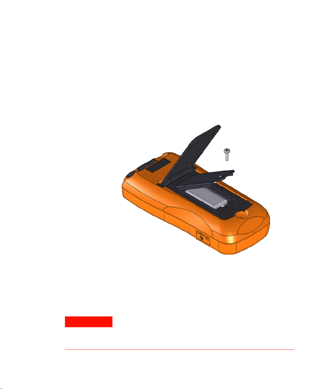
1 Open the battery cover. Lift the tilt stand. Loosen the
screw with a suitable Phillips screwdriver and remove the
battery cover as shown in Figure 1-1.
2 Insert the battery. Observe the proper battery polarity.
The terminal ends of the battery are indicated inside the
battery compartment.
3 Close the battery cover. Place the battery cover back in
its original position and tighten the screw.
4 U1731C/U1732C/U1733C User’s Guide
Figure 1-1 Installing the batteries
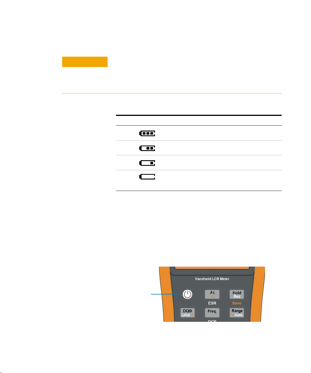
The battery level indicator in the lower right- hand corner of
the display indicates the relative condition of the battery.
Table 1- 1 describes the various battery levels the indicator
represents.
To avoid false readings, which could lead to possible electric shock
or personal injury, replace the battery as soon as the low battery
indicator appears. Do not discharge the battery by shorting the
battery or reverse the battery polarity.
Page 23
Introduction 1
CAUTION
Power-on button
Preparing Your LCR Meter
To avoid instruments being damage from battery leakage:
• Always remove dead batteries immediately.
• Always remove the battery and store it separately if the LCR meter
is not going to be used for a long period.
Tab l e 1 - 1 Battery level indicator
Indication Battery capacity
Full capacity
2/3 capacity
1/3 capacity
(Flashing periodically)
[1] Battery change advised. Always use the specified battery type listed in page 74.
Almost empty (less than one day)
[1]
Turn on your LCR meter
To power ON your LCR meter, press the power- on button
once. The LCR meter powers up in the auto identification
(Ai) mode (see page 26) when turned on for the first time.
Figure 1-2 Power-on button
U1731C/U1732C/U1733C User’s Guide 5
Page 24

1 Introduction
NOTE
NOTE
Tol%
NOTE
Preparing Your LCR Meter
To power OFF your LCR meter, press the power- on button
again.
You can change the power-on behavior of your LCR meter for subsequent
power cycles. See “Changing the initial power-on behavior” on page 54 for
more information on changing the LCR meter’s power-on setting.
Automatic Power-Off (APO)
Your LCR meter automatically turns off after 5 minutes
(default) if no keys are pressed. Pressing any key will turn
the LCR meter back on after it is powered off automatically.
The annunciator is shown on the bottom left of the
display when the APO function is enabled.
• To change the timeout period or completely disable the APO function,
refer to “Changing the auto power-off and backlight timeouts” on
page 71.
• If an
external power adapter is used, the APO function will be disabled.
Enabling the backlight
If viewing the display becomes difficult in low- light
conditions, press for more than 1 second to activate the
LCD backlight.
To conserve battery life, a user- adjustable timeout controls
how long the backlight stays on. The default timeout is 30
seconds.
• To change the timeout period or completely disable the backlight, refer
to “Changing the auto power-off and backlight timeouts” on page 71.
• If an
6 U1731C/U1732C/U1733C User’s Guide
external power adapter is used, the backlight timeout will be disabled.
Page 25

Selecting the range
Auto
Range
Auto
Range
Auto
Range
Auto
Range
Pressing switches the LCR meter between manual and
autoranging. It also cycles through the available LCR meter
ranges when manual ranging is enabled.
Autoranging is convenient because the LCR meter
automatically selects an appropriate range for sensing and
displaying each measurement. However, manual ranging
results in better performance, since the LCR meter does not
have to determine which range to use for each measurement.
In autorange, the LCR meter selects the lowest range to
display the highest available precision (resolution) for the
input signal. If manual range is already enabled, press
for more than 1 second to enter the autoranging mode.
If autoranging is enabled, press to enter the manual
range mode.
Each additional press of sets the LCR meter to the next
higher range, unless it is already in the highest range, at
which point the range switches to the lowest range.
Introduction 1
Preparing Your LCR Meter
U1731C/U1732C/U1733C User’s Guide 7
Page 26
1 Introduction
To PC (host)
IR-USB cable
Preparing Your LCR Meter
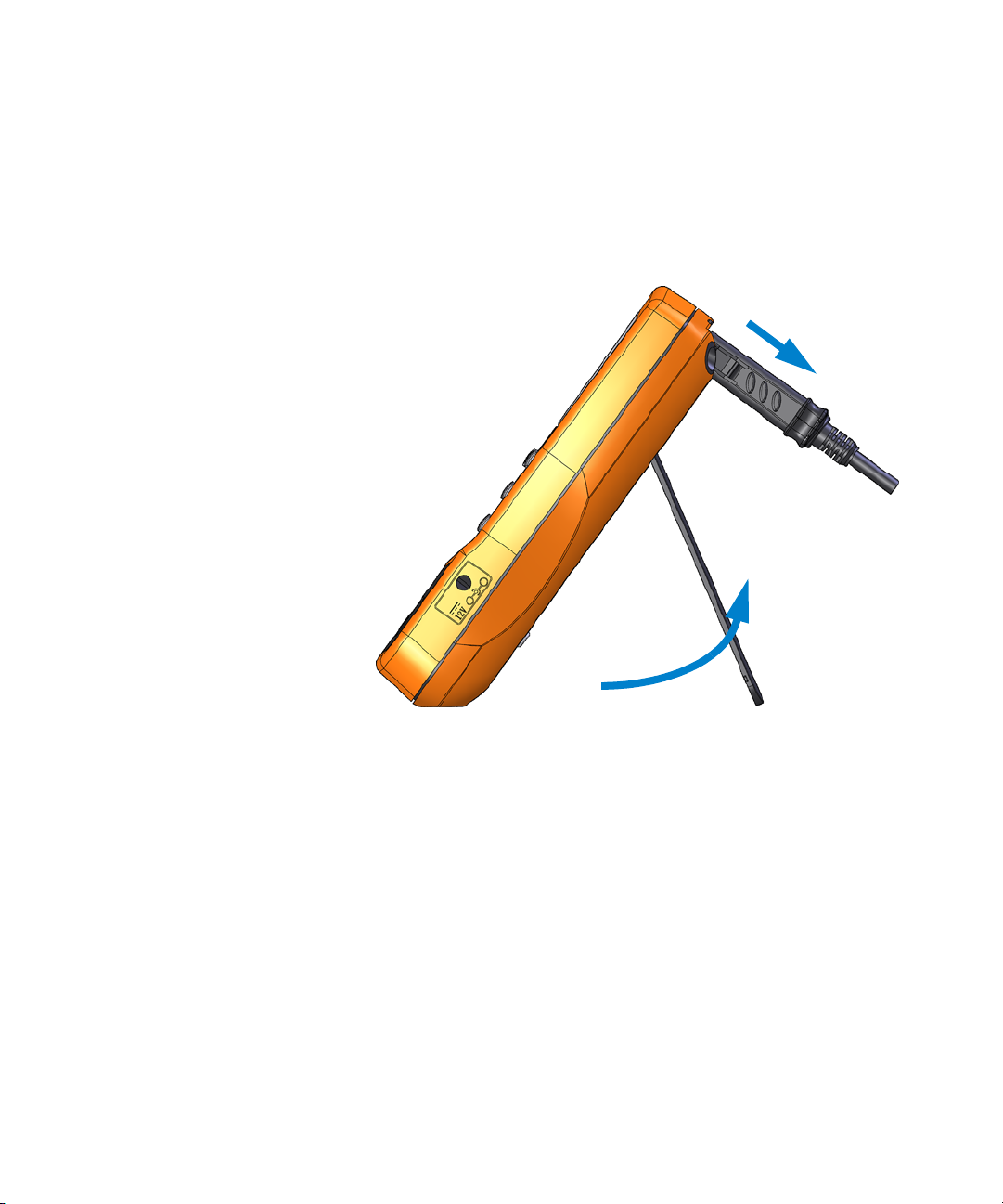
Adjusting the tilt stand
To adjust the LCR meter to a 60° standing position, pull the
tilt- stand outward to its maximum reach.
Figure 1-3 Tilt-stand adjustment and IR cable connection
8 U1731C/U1732C/U1733C User’s Guide
Page 27
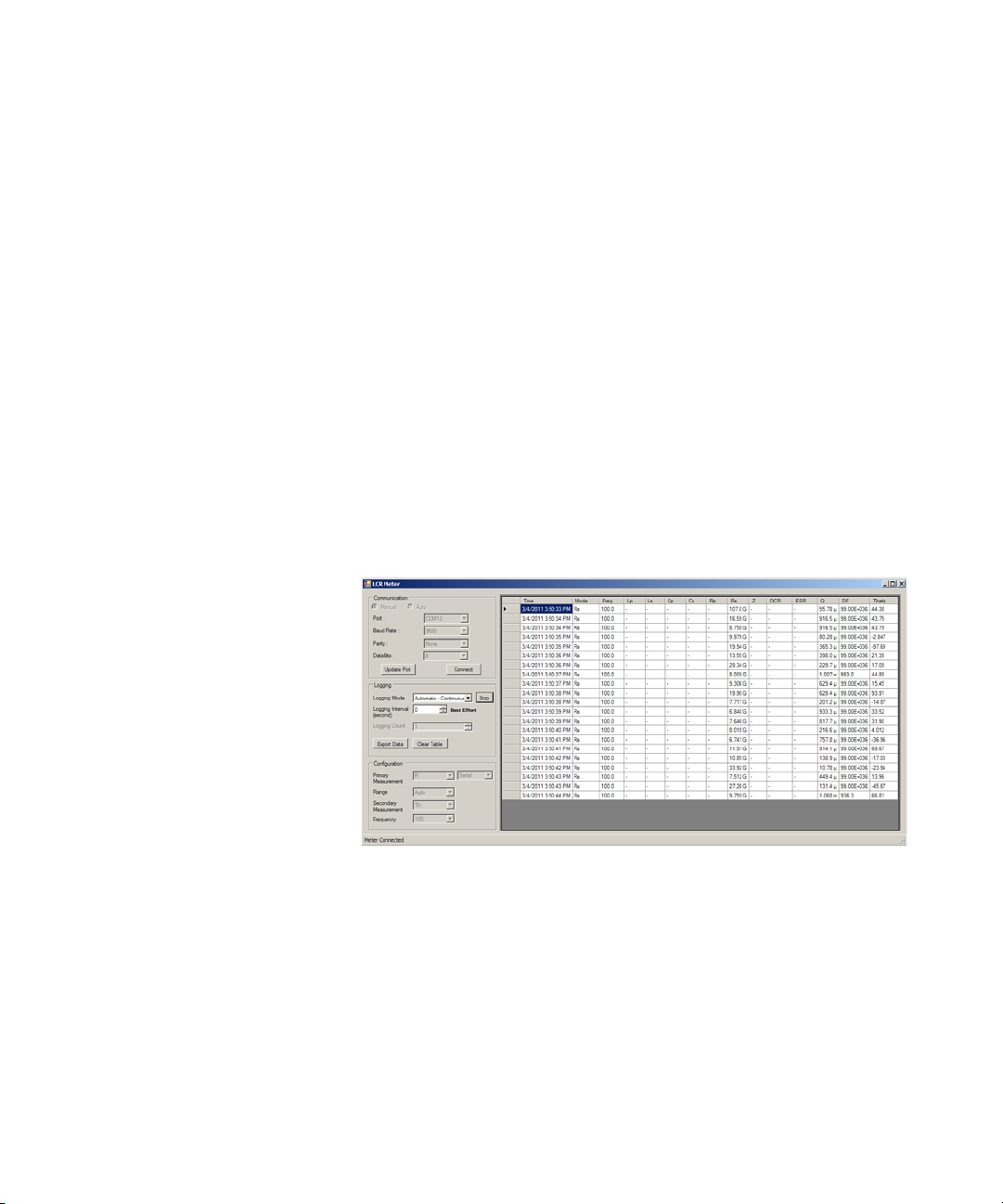
Connecting the IR-USB cable
You can use the IR communication link (IR communication
port, located at the rear panel) and the Agilent GUI Data
Logger software to control your LCR meter remotely,
perform data logging operations, and transfer the contents of
your LCR meter’s memory to a PC.
Ensure that the Agilent logo on the U5481A IR- USB cable
(purchased separately) connected to the LCR meter is facing
up. Firmly push the IR head into the LCR meter’s IR
communication port until it snaps into place (see
Figure 1- 3).
Refer to the Agilent GUI Data Logger Software Quick Start
Guide and Help for more information on the IR
communication link and the Agilent GUI Data Logger
software.
Introduction 1
Preparing Your LCR Meter
Figure 1-4 Agilent GUI Data Logger Software
The Agilent GUI Data Logger software and its supporting
documents (Quick Start Guide and Help) are available for
free download at http://www.agilent.com/find/hhTechLib.
You may purchase a U5481A IR- USB cable from an Agilent
Sales Office nearest to you.
U1731C/U1732C/U1733C User’s Guide 9
Page 28
1 Introduction
Rec
Hold
Auto
Range
Cal
Null
P S
ZLCR
P S
ZLCR
Preparing Your LCR Meter
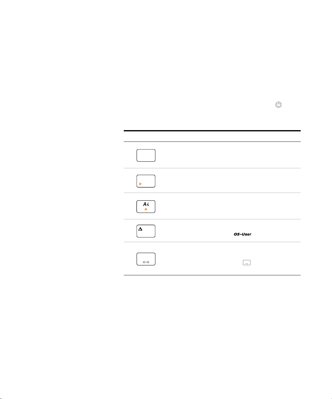
Power-on options
Some options can be selected only while you turn the LCR
meter on. These power- on options are listed in the table
below.
To select a power- on option, press and hold the specified
key in Table 1- 2 while turning the LCR meter ON ( ).
Tab l e 1 - 2 Power-on options
Key Description
Tests the LCD.
All annunciators are displayed in the LCD. Press any key to
exit this mode.
Simulates the Auto Power-Off (APO) mode. Press any key
to turn the LCR meter back on and resume normal
operation.
Checks the firmware version.
The LCR meter’s firmware version will be shown on the
primary display. Press any key to exit this mode.
Performs the Open/Short correction on all frequencies and
all ranges for the User mode ( ).
[1]
Enters the Setup menu.
See Chapter 3, “Setup Options,” starting on page 49 for
more information. Press and hold for more than 1
second to exit this mode.
[1] The Open/Short correction requires approximately 1.5 minutes to complete.
10 U1731C/U1732C/U1733C User’s Guide
Page 29
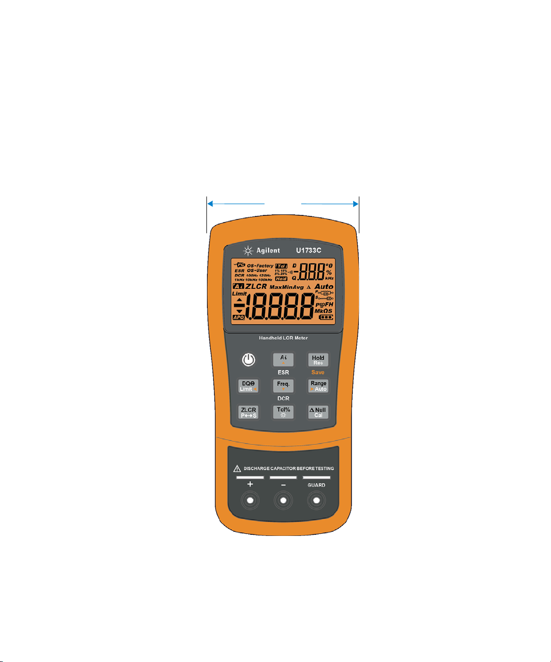
Your LCR Meter in Brief
87 mm
Dimensions
Front view
Introduction 1
Your LCR Meter in Brief
Figure 1-5 Width dimensions
U1731C/U1732C/U1733C User’s Guide 11
Page 30
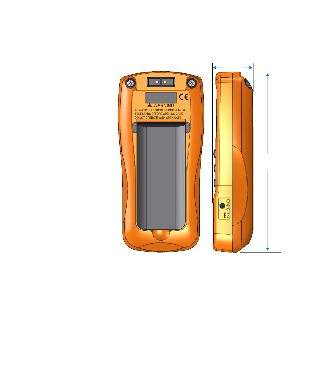
1 Introduction
184 mm
41 mm
Your LCR Meter in Brief
Rear and side view
Figure 1-6 Height and depth dimensions
12 U1731C/U1732C/U1733C User’s Guide
Page 31
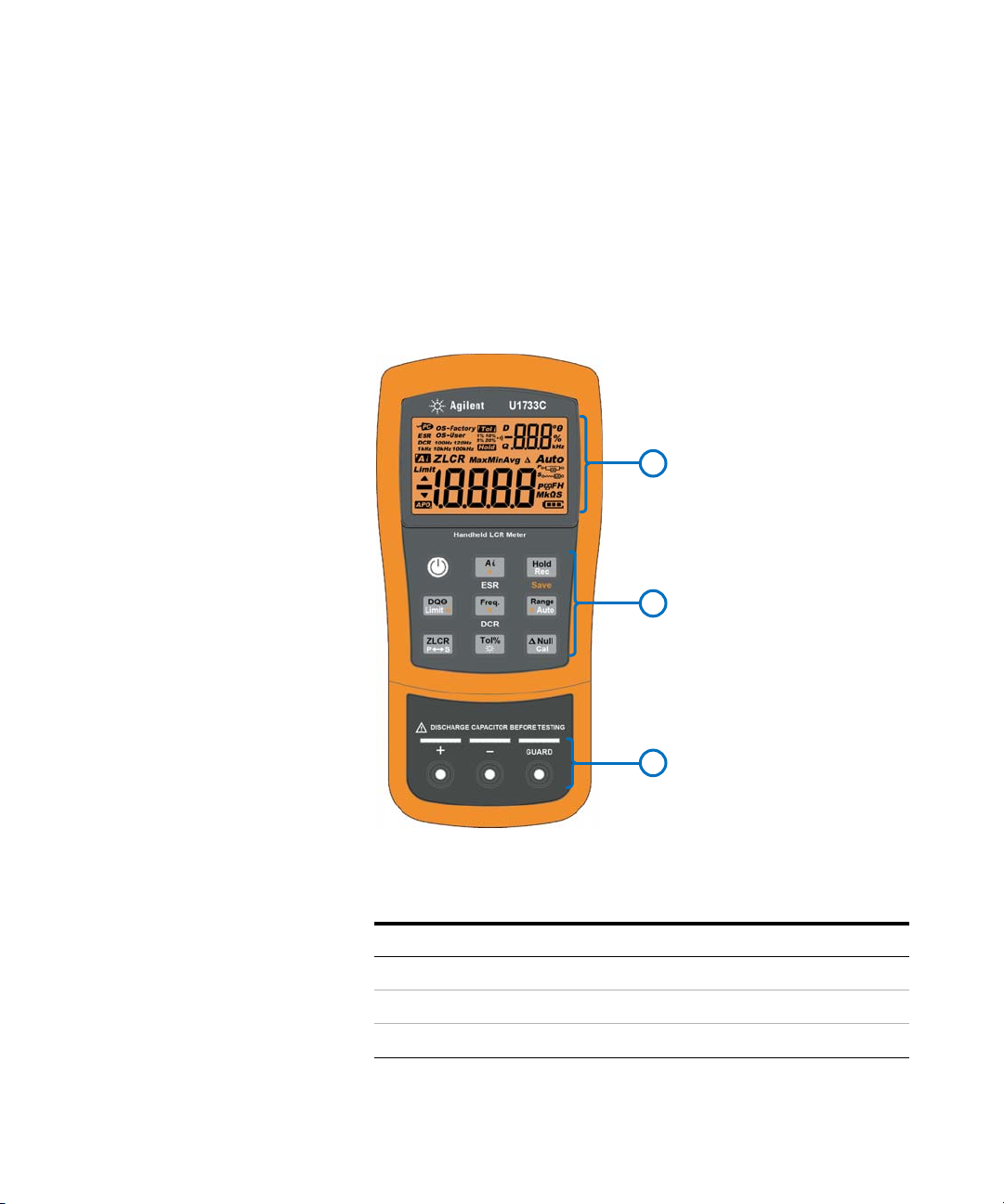
Overview
1
2
3
Introduction 1
Your LCR Meter in Brief
Front panel
The front panel parts of your LCR meter are described in
this section. Click the respective “Learn more” pages in
Table 1- 3 for more information on each part.
Figure 1-7 Front panel
Tab l e 1 - 3 Front panel parts
Legend Description Learn more on:
U1731C/U1732C/U1733C User’s Guide 13
1 Display screen page 18
2 Keypad page 15
3 Input terminals and sockets page 22
Page 32

1 Introduction
1
2
3
4
Your LCR Meter in Brief
Rear panel
The rear panel parts of your LCR meter are described in
this section. Click the respective “Learn more” pages in
Table 1- 4 for more information on each part.
Figure 1-8 Rear panel
Tab l e 1 - 4 Rear panel parts
Legend Description Learn more on:
1 IR communication port page 9
2 Tilt stand page 8
3 Battery cover (lift the tilt stand for access) page 3
4 External power adapter input jack
[1] The external power adapter input jack requires an input voltage of +12 VDC.
[1]
-
14 U1731C/U1732C/U1733C User’s Guide
Page 33

Keypad
ESR
Rec
Hold
Save
Rec
Hold
Rec
Hold
Rec
Hold
Rec
Hold
Tab l e 1 - 5 Keypad functions
Introduction 1
Your LCR Meter in Brief
The operation of each key is explained below. Pressing a key
enables a function, displays a related annunciator, and emits
a beep.
Each key operation of the U1731C/U1732C/U1733C keypad
(shown in Figure 1-7) is described in Table 1- 5. Click the
respective “Learn more” pages in Table 1- 5 for more
information on each function.
Legend
Function when pressed for:
Less than 1 second More than 1 second
Learn
more on:
Turns the LCR meter on or off. - page 5
Enables or disables the ESR (equivalent
Starts or stops the auto identification mode.
• Press again while the
annunciator is shown to exit this mode.
series resistance) mode.
• Press for more than 1 second to exit
this mode. The LCR meter will return to
page 26
capacitance measurement by default.
Holds or releases the present reading on the
display.
• Press again to update the reading
automatically once it is stable.
• Press for more than 1 second to exit
this mode.
Starts or stops the static recording mode.
• Press again to cycle through the
maximum (Max), minimum (Min), average
(Avg), and present (MaxMinAvg)
readings.
• Press for more than 1 second to exit
this mode.
page 40
U1731C/U1732C/U1733C User’s Guide 15
Page 34

1 Introduction
Limit
DQO
Limit
DQO
Auto
Range
Freq.
Rec
Hold
Limit
DQO
DCR
Freq.
Freq.
Freq.
Auto
Range
Auto
Range
P S
ZLCR
Tol%
Tol%
Tol%
Your LCR Meter in Brief
Tab l e 1 - 5 Keypad functions (continued)
Legend
Function when pressed for:
Less than 1 second More than 1 second
Switches between the dissipation factor (D),
quality factor (Q), or phase angle (θ)
measurement.
Selects a test frequency.
• Press again to cycle through the
various test frequencies (100 Hz to
100 kHz).
Disables autoranging and sets a manual
range.
• Press again to cycle through each
available measurement range.
Learn
more on:
Enables or disables the limit comparison
mode.
• While the annunciator is flashing,
• press and again to toggle
between high (H) or low (L) limits, then
• use the and keys to select a
high/low limit set (1 to 16).
• Press to start the limit sorting (with
page 37
and
page 42
the selected limit set), or
• If no activity is detected after 3 seconds,
the limit comparison will begin.
• Press for more than 1 second to exit
this mode.
U1733C only: Enables or disables the DCR
(direct current resistance) mode.
• Press for more than 1 second to exit
page 37
this mode. The LCR meter will return to
inductance measurement by default.
Enables autoranging. page 7
Switches between impedance (Z),
inductance (L), capacitance (C), and
resistance (R) measurement.
Toggles between parallel and series circuit
mode.
page 27 to
page 35
and
page 37
Sets the tolerance mode.
• Connect/insert an appropriate component
into the input terminals/sockets and press
to set the value shown on the
secondary display as the standard
reference value.
• Press again to cycle through the
Turns the LCD backlight on for 15 seconds
(default) or off.
• To change the backlight timeout refer to
“Changing the auto power-off and
backlight timeouts” on page 71.
page 38
and page 6
various tolerance values (1% to 20%).
16 U1731C/U1732C/U1733C User’s Guide
Page 35

Tab l e 1 - 5 Keypad functions (continued)
Cal
Null
Cal
Null
Cal
Null
Introduction 1
Your LCR Meter in Brief
Legend
Function when pressed for:
Less than 1 second More than 1 second
Sets the null/relative mode.
• The displayed value is saved as a
reference to be subtracted from
subsequent measurements.
• Press again to cancel the null mode.
Enters the open/short calibration mode for
the selected range and test frequency.
• Follow the prompts on the screen (open or
short connector) and press to begin
the calibration process.
• The LCR meter will return to normal
display when the calibration is complete.
Learn
more on:
page 45
and
page 46
U1731C/U1732C/U1733C User’s Guide 17
Page 36

1 Introduction
Your LCR Meter in Brief
Display screen
The function that each display annunciator of your LCR
meter is associated to is described in this section. See also
“Measurement units” on page 21 for a list of available
measurement signs and notations.
General display annunciators
The general display annunciators of your LCR meter are
described in the table below.
Each display annunciator of the U1731C/U1732C/U1733C
display screen (shown in Figure 1- 7) is described in
Table 1- 6. Click the respective “Learn more” pages in
Table 1- 6 for more information on each annunciator.
Tab l e 1 - 6 General annunciators
Legend Description Learn more on:
Remote control via PC indicator page 9
Equivalent series resistance indicator
Resistance measurement by direct current
indicator
LCR meter using open/short correction
settings by factory
LCR meter using open/short correction
setting by user
Measuring frequency of test signal is 100 Hz
Measuring frequency of test signal is 120 Hz
Measuring frequency of test signal is 1 kHz
Measuring frequency of test signal is 10 kHz
Measuring frequency of test signal is 100 kHz
page 46
page 37
18 U1731C/U1732C/U1733C User’s Guide
Page 37

Introduction 1
Your LCR Meter in Brief
Tab l e 1 - 6 General annunciators (continued)
Legend Description Learn more on:
Tolerance mode indicator for sorting L, C, or R
Tolerance set to 1% for sorting capacitance
Tolerance set to 5% for sorting capacitance
Tolerance set to 10% for sorting capacitance
Tolerance set to 20% for sorting capacitance
Data hold mode indicator page 40
Audible alert indicator for tolerance or limit
mode
Dissipation factor indicator
Quality factor indicator
Phase angle of impedance indicator
Secondary display -
Measurement units for the secondary display page 21
Impedance measurement indicator page 35
page 38
page 69
page 37
Inductance measurement indicator page 29
Capacitance measurement indicator page 31
Resistance measurement indicator page 33
U1731C/U1732C/U1733C User’s Guide 19
Page 38

1 Introduction
Your LCR Meter in Brief
Tab l e 1 - 6 General annunciators (continued)
Legend Description Learn more on:
Present reading shown on primary display
Maximum reading shown on primary display
page 40
Minimum reading shown on primary display
Averaged reading shown on primary display
Relative (Null) indicator page 45
Autoranging indicator page 7
Limit mode indicator
Reading out of HI limit
Reading out of LO limit
Auto power-off indicator page 6
Primary display -
Measurement units for the primary display page 21
Parallel mode indicator
Series mode indicator
Battery capacity indicator page 5
page 42
page 37
20 U1731C/U1732C/U1733C User’s Guide
Page 39

Introduction 1
Your LCR Meter in Brief
Measurement units
The available signs and notations for each measurement
function in your LCR meter are described in Table 1- 7. The
units listed below are applicable to the primary display
measurements of your LCR meter.
Tab l e 1 - 7 Measurement units display
Sign/Notation Description
M Mega 1E+06 (1000000)
k kilo 1E+03 (1000)
m milli 1E–03 (0.001)
μ micro 1E–06 (0.000001)
n nano 1E–09 (0.000000001)
p pico 1E–12 (0.000000000001)
° Degree, unit for phase angle measurement
% Percentage, unit for tolerance measurement
μH, mH, H Henry, units for inductance measurement
pF, nF, μF, mF Farad, units for capacitance measurement
Ω, kΩ, MΩ Ohm, units for resistance and impedance measurement
kHz, Hz Hertz, units for frequency measurement
U1731C/U1732C/U1733C User’s Guide 21
Page 40

1 Introduction
WARNING
+
-
GUARD
Your LCR Meter in Brief
Input terminals
The terminal and socket connections of your LCR meter are
described in the table below.
To avoid damaging this instrument, do not exceed the input limit. Do
not apply voltage to input terminals. Discharge the capacitor before
testing.
Tab l e 1 - 8 Input terminal/socket connections
Input
terminal/socket
Description
Positive terminal/component socket
Negative terminal/component socket
Guard terminal/component socket
22 U1731C/U1732C/U1733C User’s Guide
Page 41

Cleaning Your LCR Meter
WARNING
To avoid electrical shock or damage to the LCR meter, ensure that the
insides of the casing stay dry at all times.
Dirt or moisture in the terminals can distort readings.
Follow the steps below to clean your LCR meter.
1 Turn the LCR meter off and remove the test leads.
2 Turn the LCR meter over and shake out any dirt that may
3 Wipe the case with a damp cloth and mild detergent — do
4 Wipe the contacts in each terminal with a clean swab
Introduction 1
Cleaning Your LCR Meter
have accumulated in the terminals.
not use abrasives or solvents.
dipped in alcohol.
U1731C/U1732C/U1733C User’s Guide 23
Page 42

1 Introduction
Cleaning Your LCR Meter
THIS PAGE HAS BEEN INTENTIONALLY LEFT BLANK.
24 U1731C/U1732C/U1733C User’s Guide
Page 43

U1731C/U1732C/U1733C Handheld LCR Meter
User’s Guide
2 Features and Functions
Making Measurements 26
Auto Identification (Ai) function 26
Measuring inductance (L) 29
Measuring capacitance (C) 31
Measuring resistance (R) 33
Measuring impedance (Z) 35
Measuring dissipation factor/quality factor/phase angle (D/Q/θ) 37
Changing the test frequency 37
Selecting parallel/series circuit mode (P/S) 37
Setting the standard reference tolerance (Tol%) 38
Enabling ESR measurements 39
Enabling DCR measurements 39
Additional Features 40
Freezing the display (Hold) 40
Enabling the static recording mode (Rec) 40
Setting the high/low limit comparison (Limit) 42
Making relative measurements (Null) 45
Performing the open/short calibration (Cal) 46
This chapter provides detailed information on the features
and functions that are available in your LCR meter.
Agilent Technologies
25
Page 44

2 Features and Functions
NOTE
Making Measurements
Making Measurements
Auto Identification (Ai) function
Press to automatically identify the appropriate
measurement required for the device- under- test (DUT).
Figure 2-1 Using the Ai function
The annunciator will f lash while the LCR meter
identifies the DUT, and
• selects an appropriate measurement in the primary
display (L, C, or R) and secondary display (D, Q, or θ),
• selects an appropriate range, and
• selects an appropriate measuring mode (series or
parallel).
The Ai function helps to identify L, C, and R measurements automatically
according to the angle of impedance detected in the DUT. See Table 2-1 for
the phase angle rules.
The default phase angle condition is set to 10°. You can change this angle
in the Setup menu from 5° to 45°. See “Changing the Ai function’s phase
angle condition” on page 61 for more information.
26 U1731C/U1732C/U1733C User’s Guide
Page 45

The measurement mode (series or parallel) will be
automatically identified from the autoranging direction.
Table 2- 2, Table 2- 3, and Table 2- 4 list down the
series/parallel rules used.
Tab l e 2 - 1 Auto identification phase angle rules
Features and Functions 2
Making Measurements
Phase angle
–Set < θ < +Set R θ
θ ≥ +Set LQ
θ ≤ –Set CD
[1] Where ±Set is the phase angle selected.
[1]
Primary display Secondary display
Tab l e 2 - 2 Auto identification series/parallel rules for resistance measurements
Resistance range Down range Up range
200 MΩ Parallel Parallel
20 MΩ Parallel Parallel
2000 kΩ Parallel Parallel
200 kΩ Parallel Parallel
20 kΩ Parallel Series
2000 Ω Parallel Series
200 Ω Parallel Series
20 Ω Series Series
2 Ω Series Series
U1731C/U1732C/U1733C User’s Guide 27
Page 46

2 Features and Functions
Making Measurements
Tab l e 2 - 3 Auto identification series/parallel rules for capacitance measurements
Range
20 mFSeriesSeriesSeriesSeries------
2000 μFSeriesSeriesSeriesSeriesSeriesSeries----
200 μF Series Series Series Series Series Series Series Series - -
20 μF Series Parallel Series Parallel Series Series Series Series Series Series
2000 nF Series Parallel Series Parallel Series Parallel Series Series Series Series
200 nF Series Parallel Series Parallel Series Parallel Series Parallel Series Series
20 nF Parallel Parallel Parallel Parallel Series Parallel Series Parallel Series Parallel
2000 pF Parallel Parallel Parallel Parallel Parallel Parallel Series Parallel Series Parallel
200 pF ----ParallelParallelParallelParallelSeriesParallel
20 pF ------ParallelParallelParallelParallel
100 Hz 120 Hz 1 kHz 10 kHz 100 kHz
Down Up Down Up Down Up Down Up Down Up
Tab l e 2 - 4 Auto identification series/parallel rules for inductance measurements
Range
100 Hz 120 Hz 1 kHz 10 kHz 100 kHz
Down Up Down Up Down Up Down Up Down Up
2000 HParallelParallelParallelParallelParallelParallel----
200 H Parallel Parallel Parallel Parallel Parallel Parallel Parallel Parallel - -
20 H Parallel Series Parallel Series Parallel Parallel Parallel Parallel Parallel Parallel
2000 mH Parallel Series Parallel Series Parallel Series Parallel Parallel Parallel Parallel
200 mH Parallel Series Parallel Series Parallel Series Parallel Series Parallel Parallel
20 mH Series Series Series Series Parallel Series Parallel Series Parallel Series
2000 μH Series Series Series Series Series Series Parallel Series Parallel Series
200 μH ----SeriesSeriesSeriesSeriesParallelSeries
20 μH ------SeriesSeriesSeriesSeries
28 U1731C/U1732C/U1733C User’s Guide
Page 47

Measuring inductance (L)
NOTE
Freq.
P S
ZLCR
Limit
DQO
Set up your LCR meter to measure inductance as shown in
Figure 2- 3.
It is recommended that you perform the Open/Short calibration (see
page 46) before testing to achieve optimum precision for all inductance,
capacitance, and resistance measurements at either the highest or lowest
ranges.
1 Press to power on the LCR meter.
2 Press to select a suitable test frequency, and
i press to enable the auto identification function; or
ii alternatively press to select inductance
measurement.
Features and Functions 2
Making Measurements
Figure 2-2 Inductance measurement with Q factor
3 Insert an inductor into the component socket or connect
the test clip to the component leads as required.
4 Press to change the secondary display measurement
(D, Q, or θ).
5 Read the displays.
U1731C/U1732C/U1733C User’s Guide 29
Page 48

2 Features and Functions
Induct or
3
2
P S
ZLCR
>
Freq.
1
>
Freq.
OR
OR
Surface Mount
Device (SMD)
SMD Tweezer
Making Measurements
Figure 2-3 Measuring inductance
30 U1731C/U1732C/U1733C User’s Guide
Page 49

Measuring capacitance (C)
WARNING
Freq.
P S
ZLCR
Limit
DQO
Set up your LCR meter to measure capacitance as shown in
Figure 2- 5.
To avoid electrical hazards, discharge the capacitor to be tested
before measuring.
1 Press to power on the LCR meter.
2 Press to select a suitable test frequency, and
i press to enable the auto identification function; or
ii alternatively press to select capacitance
measurement.
Features and Functions 2
Making Measurements
Figure 2-4 Capacitance measurement with D factor
3 Insert a capacitor into the component socket or connect
the test clip to the component leads as required.
4 Press to change the secondary display measurement
(D, Q, or θ).
5 Read the displays.
U1731C/U1732C/U1733C User’s Guide 31
Page 50

2 Features and Functions
Capacitor
3
2
P S
ZLCR
>
Freq.
1
>
Freq.
OR
OR
Surface Mount
Device (SMD)
SMD Tweezer
Making Measurements
Figure 2-5 Measuring capacitance
32 U1731C/U1732C/U1733C User’s Guide
Page 51

Measuring resistance (R)
CAUTION
Freq.
P S
ZLCR
Set up your LCR meter to measure resistance as shown in
Figure 2- 7.
To avoid possible damage to your LCR meter or to the equipment under
test, disconnect the circuit power and discharge all high-voltage
capacitors before measuring resistance.
1 Press to power on the LCR meter.
2 Press to select a suitable test frequency, and
i press to enable the auto identification function; or
ii alternatively press to select resistance
measurement.
Features and Functions 2
Making Measurements
Figure 2-6 Resistance measurement
3 Insert a resistor into the component socket or connect the
test clip to the component leads as required.
4 Read the display.
U1731C/U1732C/U1733C User’s Guide 33
Page 52

2 Features and Functions
Resistor
3
2
P S
ZLCR
>
Freq.
1
>
Freq.
OR
OR
Surface Mount
Device (SMD)
SMD Tweezer
Making Measurements
Figure 2-7 Measuring resistance
34 U1731C/U1732C/U1733C User’s Guide
Page 53

Measuring impedance (Z)
NOTE
Freq.
P S
ZLCR
All circuit components, resistors, capacitors, and inductors
have parasitic components. These include, for example,
unwanted resistance in capacitors, unwanted capacitance in
inductors, and unwanted inductance in resistors. Thus,
simple components should be modeled as complex
impedances.
Set up your LCR meter to measure impedance as shown in
Figure 2- 9.
To learn more about impedance measurement theories, refer to the
Impedance Measurement Handbook. This document can be downloaded
from our website at http://www.agilent.com/find/lcrmeters.
1 Press to power on the LCR meter.
2 Press to select a suitable test frequency, and press
to select impedance measurement.
Features and Functions 2
Making Measurements
Figure 2-8 Impedance measurement with theta
3 Insert a component into the component socket or connect
the test clip to the component leads as required.
U1731C/U1732C/U1733C User’s Guide 35
Page 54

2 Features and Functions
Limit
DQO
3
Device-Under-Test
(DUT )
2
P S
ZLCR
>
Freq.
OR
Surface Mount
Device (SMD)
SMD Tweezer
1
Making Measurements
4 Press to change the secondary display measurement
(D, Q, or θ).
5 Read the displays.
Figure 2-9 Measuring impedance
36 U1731C/U1732C/U1733C User’s Guide
Page 55

Features and Functions 2
Limit
DQO
Freq.
P S
ZLCR
Making Measurements
Measuring dissipation factor/quality factor/phase angle
(D/Q/θ)
The dissipation factor (D), quality factor (Q), and phase
angle (θ) values can be displayed interchangeably by
pressing the key when the LCR meter is set to the
inductance, capacitance, or impedance measurement mode.
This setting is not applicable for DCR measurement.
Changing the test frequency
The test frequency is set to 1 kHz by default. Press the
key to select a desired test frequency.
Tab l e 2 - 5 Available test frequencies
Model 100 Hz 120 Hz 1 kHz 10 kHz 100 kHz
U1731C
U1732C
U1733C
✔✔✔
✔✔✔✔
✔✔✔✔✔
--
-
Selecting parallel/series circuit mode (P/S)
The LCR meter can display parallel ( ) or series
( ) mode data for all ranges.
Press the key for more than 1 second to toggle the
parallel and series mode.
Series mode is set as the default setting. You can, however,
change this power-on behavior in the Setup menu. See
“Changing the initial power-on behavior” on page 54 for
more information on how to change the default measurement
mode (parallel or series) for subsequent power cycles.
U1731C/U1732C/U1733C User’s Guide 37
Page 56

2 Features and Functions
Tol%
Tol%
NOTE
Making Measurements
Setting the standard reference tolerance (Tol%)
The tolerance ranges available are 1%, 5%, 10%, and 20%.
To enable the tolerance mode, insert an appropriate
component as a standard value into the component socket or
connect the test clip to the component leads, then press the
key to set this value as the standard reference tolerance.
Similarly, any value which appears on the display, such as
Hold or Max/Min/Avg (Rec), can be used as a standard value
to sort components. Press again to cycle through 1%, 5%,
10%, and 20% tolerance as desired.
This function is designed for convenient component sorting.
The beeper will beep three times whenever the component
under test exceeds the setting tolerance. Conversely, when
the beeper beeps once, this indicates that the component is
within the setting tolerance.
Figure 2-10 Component above setting tolerance
• The tolerance mode cannot be activated if is shown on the display
or when the tested capacitance value is below 50 counts.
• Tolerance mode is only available in manual ranging; therefore,
activation while in autoranging will automatically set the LCR meter to
manual ranging.
38 U1731C/U1732C/U1733C User’s Guide
Page 57

Enabling ESR measurements
Freq.
Freq.
Press for more than 1 second to select the ESR
measurement. Use the ESR measurement to measure the
equivalent series resistance of the capacitor, independent of
its capacitance.
Figure 2-11 ESR measurement with theta
Press for more than 1 second to exit this mode.
Features and Functions 2
Making Measurements
Enabling DCR measurements
Press for more than 1 second to select the DCR
measurement. The DCR measurement measures the
resistance of an unknown component by 1 VDC.
Figure 2-12 DCR measurement
Press for more than 1 second to exit this mode.
U1731C/U1732C/U1733C User’s Guide 39
Page 58

2 Features and Functions
Rec
Hold
Rec
Hold
Rec
Hold
Rec
Hold
Additional Features
Additional Features
Freezing the display (Hold)
To freeze the display for any function, press the key.
The annunciator is shown on the display while the
Hold function is active.
Figure 2-13 Using the Hold function
Press again to update the reading automatically once it
is stable. The annunciator flashes while waiting for
the reading to be stable.
Press for more than 1 second to release the Hold
function.
Enabling the static recording mode (Rec)
The static recording mode stores the maximum, minimum,
and average input values during a series of measurements in
the LCR meter’s memory.
40 U1731C/U1732C/U1733C User’s Guide
Page 59

Features and Functions 2
Rec
Hold
Rec
Hold
> 1 s
Rec
Hold
Rec
Hold
Additional Features
When the input goes below the recorded minimum value or
above the recorded maximum value, the LCR meter beeps
and records the new value. The LCR meter also calculates
an average of all readings taken since the static recording
mode was activated.
From the LCR meter’s display, you can view the following
statistical data for any set of readings:
• Max: highest reading since the static recording mode was
enabled
• Min: lowest reading since the static recording mode was
enabled
• Avg: average or mean of all readings since the static
recording mode was enabled
• MaxMinAvg: present reading (actual input signal value)
Press the key for more than 1 second to enter the static
recording mode.
Figure 2-14 Using the Rec function
Press again to cycle through the Max, Min, Avg, or
MaxMinAvg (present) input values.
To exit this mode, press and hold the key for more than
1 second.
U1731C/U1732C/U1733C User’s Guide 41
Page 60

2 Features and Functions
NOTE
Additional Features
• Static recording captures only stable values and updates the memory; it
will not record any overload ( ) value for any of the LCR functions. In
addition, the LCR meter will not record values below 50 counts in
capacitance measurement.
• Static recording is only available in manual ranging; therefore,
activation while in autoranging will automatically set the LCR meter to
manual ranging.
Setting the high/low limit comparison (Limit)
The high and low limit comparison function helps you to
sort components easily. There are 32 limit sets available (16
fixed factory sets, and 16 variable user sets).
The LCR meter will use the factory sets by default. You can
set the LCR meter to use the user sets upon start-up from
the Setup menu. See “Changing the power- on limit category
and set” on page 63 for more information.
Table 2- 6 shows the factory default limit values for each set.
Tab l e 2 - 6 Factory default high and low limit values
Set High limit (H) Low limit (L)
F01 1000 900
F02 1200 1080
F03 1500 1350
F04 1800 1620
F05 2200 1980
F06 2700 2430
F07 3300 2970
F08 3900 3510
F09 4700 4230
42 U1731C/U1732C/U1733C User’s Guide
Page 61

Features and Functions 2
NOTE
Limit
DQO
Limit
DQO
> 1 s
Additional Features
Tab l e 2 - 6 Factory default high and low limit values (continued)
Set High limit (H) Low limit (L)
F10 5600 5040
F11 6800 6120
F12 8200 7380
F13 10000 9000
F14 12000 10800
F15 15000 13500
F16 18000 16200
The default values of the variable user sets are set to the same as the fixed
user sets. Use the Setup menu to change the high and low limits for each
set. See “Changing the user high/low limit values” on page 64 for more
information.
Press the key for more than 1 second to activate the
high/low limit mode. The last- known set number (H## or
L##) will be indicated in the secondary display.
Figure 2-15 Using the Limit function
U1731C/U1732C/U1733C User’s Guide 43
Page 62

2 Features and Functions
Freq.
Limit
DQO
Auto
Range
Rec
Hold
Additional Features
While the annunciator is flashing, use the or
key to select an appropriate limit set.
You may press or again to toggle between the high
(H) or low (L) values shown on the primary display.
Figure 2-16 High and low limit values
Press while the annunciator is flashing to start
the comparison. (If no activity is detected after 3 seconds,
the comparison will also begin.)
The LCR meter beeps three times and displays in the
secondary display if the reading is greater ( ) than the
high limit or lesser ( ) than the low limit.
If the reading is within the high and low limits, the meter
beeps once and displays in the secondary display.
Figure 2-17 nGo and Go indications
The limit set used in the comparison is displayed after the
/ indication.
44 U1731C/U1732C/U1733C User’s Guide
Page 63

Press and hold for more than 1 second to exit this
Limit
DQO
Cal
Null
Cal
Null
mode.
Making relative measurements (Null)
When making relative measurements, also called null, each
reading is the difference between a stored (selected or
measured) relative value and the input signal.
One possible application is to increase the accuracy of a
resistance measurement by nulling the test lead resistance
(test leads shorted). Nulling the leads is also particularly
important prior to making capacitance measurements (test
leads open).
Press the key to enter the relative mode and store the
display reading as a reference value. The LCR meter will
then display all subsequent readings relative to the reference
value.
Features and Functions 2
Additional Features
Figure 2-18 Using the Null function
U1731C/U1732C/U1733C User’s Guide 45
Page 64

2 Features and Functions
Cal
Null
NOTE
Cal
Null
Additional Features
The annunciator is shown on the display while the
relative mode is active. Press again to exit the relative
mode.
• The relative mode cannot be activated if the display value is .
• Relative mode is only available in manual ranging; therefore, activation
while in autoranging will automatically set the LCR meter to manual
ranging.
• The relative mode cannot be activated if the LCR meter is set at
auto-ranging with data hold activated.
Performing the open/short calibration (Cal)
The corrections for the and are
pre-stored in the LCR meter. They are both calibrated at the
terminal ends.
You can set the LCR meter to start up using the
or open/short correction from the Setup menu (see
page 60).
There are three types of open/short corrections available:
• OS- Factory: Re- calibration requires you to enter the LCR
meter’s calibration mode (security code protected)
• OS- User: Re- calibration is possible through the power- on
options (see page 10).
• Quick range: Single range and frequency as required by
pressing and holding the key for more than 1 second
The calibration function is available for fixed measurement
ranges.
The correction calibrates the meter's internal parameters as
well as external connector residues for further measuring.
This action will help you to correct the influence for
temporary uses. It is highly recommended that you calibrate
extremely high or low ranges for L, C, and R measurements
before making precision measurements.
46 U1731C/U1732C/U1733C User’s Guide
Page 65

Features and Functions 2
Cal
Null
Cal
Null
> 1 s
Cal
Null
Additional Features
Press and hold the key for more than 1 second to enter
calibration mode for the selected frequency and range.
Figure 2-19 Using the Cal function
Calibration prompts will be shown on the display. Follow the
prompts for open connector (OPn) or short connector (SHor)
connection and press the key.
Figure 2-20 Open calibration and short calibration prompts
After calibration is completed, the LCR meter will be
restored to normal display and ready for normal usage.
U1731C/U1732C/U1733C User’s Guide 47
Page 66

2 Features and Functions
Additional Features
THIS PAGE HAS BEEN INTENTIONALLY LEFT BLANK.
48 U1731C/U1732C/U1733C User’s Guide
Page 67

U1731C/U1732C/U1733C Handheld LCR Meter
User’s Guide
3 Setup Options
Using the Setup Menu 50
Editing numerical values 51
Setup Menu Summary 52
Setup Menu Items 54
Changing the initial power-on behavior 54
Changing the Ai function’s phase angle condition 61
Changing the power-on limit category and set 63
Changing the user high/low limit values 64
Changing the baud rate 66
Changing the parity check 67
Changing the data bits 68
Changing the beep frequency 69
Locking the push buttons 70
Changing the auto power-off and backlight timeouts 71
Resetting the Setup items 72
The following chapter describes how to change the preset
features of your LCR meter.
Agilent Technologies
49
Page 68

3Setup Options
P S
ZLCR
P S
ZLCR
P S
ZLCR
Limit
DQO
Auto
Range
Limit
DQO
Auto
Range
Freq.
Freq.
Freq.
Rec
Hold
Save
P S
ZLCR
Rec
Hold
P S
ZLCR
Using the Setup Menu
Using the Setup Menu
The Setup menu allows you to change a number of
nonvolatile preset features. Modifying these settings affects
the general operation of your LCR meter across several
functions. Select a setting to edit to perform one of the
following:
• Switch between two values, such as on or off.
• Cycle through multiple values from a predefined list.
• Decrease or increase a numerical value within a fixed
range.
The contents of the Setup menu are summarized in
Table 3- 2 on page 52.
Tab l e 3 - 1 Setup menu key functions
Legend Description
Press and hold while turning the LCR meter ON
( ) to access the Setup menu.
Press and hold for more than 1 second to exit
this mode.
Press or to step through the menu items.
Press or at each menu item to change the
preset settings. The menu item (in the secondary
display) will flash to indicate that you can now
change the menu item values.
Press or again to switch between two
values, to cycle through multiple values from a list,
or to decrease or increase a numerical value.
While the menu item is flashing, press to save
your changes.
While the menu item is flashing, press to
discard your changes.
50 U1731C/U1732C/U1733C User’s Guide
Page 69

Editing numerical values
Limit
DQO
Auto
Range
Limit
DQO
Auto
Range
Freq.
Freq.
Rec
Hold
P S
ZLCR
When editing numerical values, use the and to
position the cursor on a numerical digit.
• Press to move the cursor to the left, and
• Press to move the cursor to the right.
When the cursor is positioned over a digit, use the and
keys to change the numerical digit.
• Press to increment the digit, and
• Press to decrement the digit.
When you have completed your changes, save the new
numerical value by pressing . (Or alternatively, if you
wish to discard the changes you made press, .)
Setup Options 3
Using the Setup Menu
U1731C/U1732C/U1733C User’s Guide 51
Page 70

3Setup Options
Setup Menu Summary
Setup Menu Summary
The Setup menu items are summarized in the table below.
Click the respective “Learn more” pages for more
information on each menu item.
Tab l e 3 - 2 Setup menu item descriptions
Legend Available settings Description Learn more on:
Ai, Z, L, C, R, ESR, or DCR
100 Hz, 120 Hz, 1 kHz,
10 kHz, or 100 kHz
D, Q, or θ and P or S
D, Q, or θ and P or S
D, Q, or θ and P or S
FACt or USEr
05° to 45
°
Set the measurement type that the LCR meter powers up
in. Default is the auto identification (Ai) mode.
Set the test frequency that the LCR meter powers up in.
Default is 1 kHz.
Set the inductance (L) secondary parameter and
measurement mode that the LCR meter powers up in.
Default is quality factor (Q) and series (S).
Set the capacitance (C) secondary parameter and
measurement mode that the LCR meter powers up in.
Default is dissipation factor (D) and series (S).
Set the resistance (R) secondary parameter and
measurement mode that the LCR meter powers up in.
Default is phase angle (θ) and series (S).
Set the open/short correction mode that the LCR meter
powers up in. Default is factory (FACt).
Set the phase angle condition for the auto identification
(Ai) mode. Default is 10
°.
page 54
page 56
page 57
page 58
page 59
page 60
page 61
Ft01 to Ft16 or Ur01 to Ur16
Set the limit category (factory or user) and set (01 to 16)
that the LCR meter powers up in. Default is Ft01.
page 63
52 U1731C/U1732C/U1733C User’s Guide
Page 71

Setup Options 3
Setup Menu Summary
Tab l e 3 - 2 Setup menu item descriptions (continued)
Legend Available settings Description Learn more on:
H01 to H16 or L01 to L16
0 to 19999
9600 or 19200
En, nonE, or odd
7bit or 8bit
2000 Hz, 3000 Hz, 4000 Hz,
or oFF
oFF or on Lock the LCR meter’s push buttons. Default is off. page 70
01 to 99 mins or oFF
01 to 99 s or oFF
Set the high and low limits for each variable user set.
See Table 3-4
Set the baud rate for remote communication with a PC
(9600 or 19200). Default is 9600.
Set the parity bit for remote communication with a PC
(even, none, or odd). Default is none.
Set the data bit length for remote communication with a
PC (7-bit or 8-bit). Default is 8-bit.
Set the LCR meter’s beep frequency (2000 Hz, 3000 Hz,
4000 Hz, or off). Default is 4000 Hz.
Set the auto power-off timeout period from 1 to 99 minutes
(1 hour, 39 minutes) or off. Default is 5 minutes.
Set the LCD backlight timeout period from 1 to 99 seconds
(1 minute, 39 seconds) or off. Default is 30 seconds.
on page 64 for the user default values.
page 64
page 66
page 67
page 68
page 69
page 71
dEFA Reset the LCR meter to its factory default settings. page 72
U1731C/U1732C/U1733C User’s Guide 53
Page 72

3Setup Options
Setup Menu Items
Setup Menu Items
Changing the initial power-on behavior
You can change the power- on behavior of your LCR meter
for subsequent power cycles.
Parameter Range Default setting
Pon-tYPE Ai, Z, L, C, R, ESR, or DCR Ai
Pon-FrEq
Pon-AUto (L)
Pon-AUto (C)
Pon-AUto (R)
Pon-oSC FACt or USEr FACt
100 Hz, 120 Hz, 1 kHz, 10 kHz,
or 100 kHz
• D, Q, or °θ
• Parallel or Series
• D, Q, or °θ
• Parallel or Series
• D, Q, or °θ
• Parallel or Series
1 kHz
• Q
• Series
• D
• Series
• °θ
• Series
Changing the power-on measurement type
Use this Setup item to change the LCR meter’s initial
measurement type. You can set the LCR meter to start up in
the
• auto identification mode (Ai),
• impedance measurement (Z),
• inductance measurement (L),
• capacitance measurement (C),
• resistance measurement (R),
• equivalent series resistance mode (ESR), or
• direct current resistance mode (DCR) for U1733C only
54 U1731C/U1732C/U1733C User’s Guide
Page 73

Setup Options 3
Press
Press
Press
Press
Press
Press
Setup Menu Items
The LCR meter will start up in the selected measurement
type for subsequent power cycles.
Figure 3-1 Changing the power-on measurement type
U1731C/U1732C/U1733C User’s Guide 55
Page 74

3Setup Options
Press
Press
Press
Press
Setup Menu Items
Changing the power-on test frequency
Use this Setup item to change the LCR meter’s initial test
frequency. You can set the LCR meter to start up using a
test frequency from 100 Hz to 100 kHz.
The LCR meter will start up using the selected test
frequency for subsequent power cycles.
Figure 3-2 Changing the power-on test frequency
56 U1731C/U1732C/U1733C User’s Guide
Page 75

Setup Options 3
Press
Press
Press
Press
Press
Press
Press
Press
Setup Menu Items
Changing the power-on secondary parameter and measurement
mode for inductance (L) measurements
Use this Setup item to change the inductance (L)
measurement’s initial secondary parameter — dissipation
factor (D), quality factor (Q), or phase angle (θ) — and
measurement mode — parallel or series.
The inductance (L) measurement will start up using the
selected secondary parameter and measurement mode for
subsequent power cycles.
Figure 3-3 Changing the power-on secondary parameter and measure-
ment mode for inductance (L) measurements
U1731C/U1732C/U1733C User’s Guide 57
Page 76

3Setup Options
Press
Press
Press
Press
Press
Press
Press
Press
Setup Menu Items
Changing the power-on secondary parameter and measurement
mode for capacitance (C) measurements
Use this Setup item to change the capacitance (C)
measurement’s initial secondary parameter — dissipation
factor (D), quality factor (Q), or phase angle (θ) — and
measurement mode — parallel or series.
The capacitance (C) measurement will start up using the
selected secondary parameter and measurement mode for
subsequent power cycles.
Figure 3-4 Changing the power-on secondary parameter and measure-
ment mode for capacitance (C) measurements
58 U1731C/U1732C/U1733C User’s Guide
Page 77

Setup Options 3
Press
Press
Press
Press
Press
Press
Press
Press
Setup Menu Items
Changing the power-on secondary parameter and measurement
mode for resistance (R) measurements
Use this Setup item to change the resistance (R)
measurement’s initial secondary parameter — dissipation
factor (D), quality factor (Q), or phase angle (θ) — and
measurement mode — parallel or series.
The resistance (R) measurement will start up using the
selected secondary parameter and measurement mode for
subsequent power cycles.
Figure 3-5 Changing the power-on secondary parameter and measure-
ment mode for resistance (R) measurements
U1731C/U1732C/U1733C User’s Guide 59
Page 78

3Setup Options
Press
Press
Setup Menu Items
Changing the power-on open/short correction
Use this Setup item to change the LCR meter’s initial
open/short correction to either the factory open/short
correction (FACt), or user open/short correction (USEr).
The LCR meter will start up using the selected open/short
correction for subsequent power cycles.
Figure 3-6 Changing the power-on open/short correction
60 U1731C/U1732C/U1733C User’s Guide
Page 79

Setup Menu Items
Changing the Ai function’s phase angle condition
This setting is used with the Ai function (see page 26). The
Ai function helps to identify L, C, and R measurements
automatically according to the angle of impedance detected
in the DUT.
Use this Setup item to change the default phase angle for
the Ai function between 5° and 45°.
Parameter Range Default setting
Ai (5 to 45)° 10°
Table 3- 3 shows the correlation between the phase angle
detected and the L, C, and R measurements selected.
Tab l e 3 - 3 Auto identification phase angle rules
Setup Options 3
Phase angle
–Set < θ < +Set R θ
θ ≥ +Set LQ
θ ≤ –Set CD
[1] Where ±Set is the phase angle selected.
[1]
Primary display Secondary display
U1731C/U1732C/U1733C User’s Guide 61
Page 80

3Setup Options
Press
Press
Press
Press
Press
Press
Setup Menu Items
Figure 3-7 Changing the Ai function’s phase angle condition
62 U1731C/U1732C/U1733C User’s Guide
Page 81

Changing the power-on limit category and set
Press
Press
Press
Press
Press
Press
Press
Press
This setting is used with the Limit comparison function
(page 42). There are 32 limit sets available (16 fixed factory
sets, and 16 variable user sets).
Use this Setup item to change the default category (factory
or user) and set (1 to 16) for subsequent power cycles.
Parameter Range Default setting
Setup Options 3
Setup Menu Items
Pon
Figure 3-8 Changing the power-on limit and category set
• Factory (Ft01 to Ft16) or
• User (Ur01 to Ur16)
Ft01
U1731C/U1732C/U1733C User’s Guide 63
Page 82

3Setup Options
NOTE
Setup Menu Items
Changing the user high/low limit values
This setting is used with the Limit comparison function
(page 42). There are 16 variable user sets available.
Use this Setup item to change the high and low limits of
each variable user set.
The low limit can be set from 0 to less than or equal to the high limit, and
the high limit can be set from more than or equal to the low limit to less
than or equal to the maximum display count (19999).
Parameter Range Default setting
• H(01 to 16) or
• L(01 to 16)
0 to 19999 See Tab le 3- 4
Table 3- 4 shows the user default limit values for each set.
Tab l e 3 - 4 Default user high/low limit values
Set High limit (H) Low limit (L)
U01 1000 900
U02 1200 1080
U03 1500 1350
U04 1800 1620
U05 2200 1980
U06 2700 2430
U07 3300 2970
U08 3900 3510
U09 4700 4230
U10 5600 5040
64 U1731C/U1732C/U1733C User’s Guide
Page 83

Setup Options 3
Press
Press
Press
Press
Press
Press
Press
Press
Press
Press
Press
Press
Press
Press
Press
Press
Press
Press
Setup Menu Items
Tab l e 3 - 4 Default user high/low limit values (continued)
Set High limit (H) Low limit (L)
U11 6800 6120
U12 8200 7380
U13 10000 9000
U14 12000 10800
U15 15000 13500
U16 18000 16200
Figure 3-9 Changing the user high/low limit values
U1731C/U1732C/U1733C User’s Guide 65
Page 84

3Setup Options
Press
Press
Setup Menu Items
Changing the baud rate
This setting is used with the IR communication link and the
Agilent GUI Data Logger software to control your LCR meter
remotely (page 9).
Use this Setup item to change the baud rate for remote
communications with a PC.
Parameter Range Default setting
bPS (9600 or 19200) bits/second
Figure 3-10 Changing the baud rate
9600
bits/second
66 U1731C/U1732C/U1733C User’s Guide
Page 85

Changing the parity check
Press
Press
Press
Press
This setting is used with the IR communication link and the
Agilent GUI Data Logger software to control your LCR meter
remotely (page 9).
Use this Setup item to change the parity check for remote
communications with a PC.
Parameter Range Default setting
PAr nonE, En, or odd nonE
Setup Options 3
Setup Menu Items
Figure 3-11 Changing the parity check
U1731C/U1732C/U1733C User’s Guide 67
Page 86

3Setup Options
Press
Press
Setup Menu Items
Changing the data bits
This setting is used with the IR communication link and the
Agilent GUI Data Logger software to control your LCR meter
remotely (page 9).
Use this Setup item to change the number of data bits (data
width) for remote communications with a PC. The number of
the stop bit is always 1, and this cannot be changed.
Parameter Range Default setting
dAt 7-bit or 8-bit 8-bit
Figure 3-12 Changing the data bits
68 U1731C/U1732C/U1733C User’s Guide
Page 87

Changing the beep frequency
Press
Press
Press
Press
Press
Press
The LCR meter’s beeper alerts users to the presence of
newly sensed values for static recordings, sensed values that
are out of tolerance or limits set, as well as invalid key
operations.
Use this Setup item to change the driving frequency of the
beeper.
Parameter Range Default setting
bEP (2000, 3000, 4000) Hz or oFF 4000 Hz
Setup Options 3
Setup Menu Items
Figure 3-13 Changing the beep frequency
U1731C/U1732C/U1733C User’s Guide 69
Page 88

3Setup Options
Press
Press
Setup Menu Items
Locking the push buttons
Use this Setup item to lock the push buttons (keys) of your
LCR meter. If enabled, all keys will be locked (rendered
unoperational) when you exit the Setup menu.
Unlock the push buttons again by entering the Setup menu
through the power- on options (page 10).
Parameter Range Default setting
LPb on or oFF oFF
Figure 3-14 Locking the push buttons
70 U1731C/U1732C/U1733C User’s Guide
Page 89

Setup Options 3
Press
Press
Press
Press
Press
Press
Press
Press
Press
Press
Press
Press
Setup Menu Items
Changing the auto power-off and backlight timeouts
The LCR meter’s automatic power-off (see page 6) and
backlight (see page page 6) features use timers to determine
when to turn off the backlight and when to automatically
turn the LCR meter off.
Parameter Range Default setting
APo (01 to 99) minutes or oFF 05 minutes
bLt (01 to 99) seconds or oFF 30 seconds
Figure 3-15 Changing the auto power-off and backlight timeouts
U1731C/U1732C/U1733C User’s Guide 71
Page 90

3Setup Options
Rec
Hold
Press
Rec
Hold
Setup Menu Items
Resetting the Setup items
The Setup items can be reset to their default values through
this Setup item.
Press to perform the reset. The LCR meter will beep
once, exit the Setup menu, and return to normal operation.
Parameter Range Default setting
rSt dEFA dEFA
Figure 3-16 Resetting the Setup items
72 U1731C/U1732C/U1733C User’s Guide
Page 91

U1731C/U1732C/U1733C Handheld LCR Meter
User’s Guide
4 Characteristics and Specifications
Product Characteristics 74
Specification Assumptions 75
Electrical Specifications 76
Impedance/Resistance/DCR specifications 76
Capacitance specifications 77
Inductance specifications 78
Phase angle of impedance specifications 79
Dissipation/Quality factor specifications 80
Test signal specifications 81
Source impedance of impedance/resistance measurement 82
Source impedance of capacitance measurement 83
Source impedance of inductance measurement 84
SMD Tweezer Specifications 85
Electrical characteristics 86
This chapter lists the characteristics, assumptions, and
specifications of the U1731C, U1732C, and U1733C handheld
LCR meters.
Agilent Technologies
73
Page 92

4 Characteristics and Specifications
NOTE
Product Characteristics
Product Characteristics
Product characteristics specified in the table below are applicable for all
U1731C, U1732C, and U1733C models unless stated otherwise.
POWER SUPPLY
Battery type:
• 1 × 9 V Alkaline battery (ANSI/NEDA 1604A or IEC 6LR61), or
• 1 × 9 V Zinc Chloride battery (ANSI/NEDA 1604D or IEC 6F22)
Battery life:
• 16 hours typical (based on new Alkaline batteries without backlight enabled)
• Low battery indicator will flash when the battery voltage drops below 7.2 V
(approximately)
External DC adapter
• DC 12 V ± 10% or 10.8 V
POWER CONSUMPTION
225 mVA maximum (without backlight enabled)
MIN
to 13.2 V
MAX
DISPLAY
Dual display liquid crystal display (LCD)
• Primary display is 4 1/2 digits with maximum of 19999 counts
• Secondary display is 3 digits with maximum of 999 counts
MEASUREMENT RATE
• 1 time/second, nominal
OPERATING ENVIRONMENT
• Operating temperature from –10 °C to 55 °C, 0% to 80% RH
• Full accuracy up to 80% RH for temperatures up to 30 °C, decreasing linearly
to 50% RH at 55 °C
• Altitude up to 2000 m
• Pollution degree II
STORAGE COMPLIANCE
–20 °C to 70 °C, 0% to 80% RH
74 U1731C/U1732C/U1733C User’s Guide
Page 93

Characteristics and Specifications 4
Specification Assumptions
SAFETY AND ELECTROMAGNETIC COMPATIBILITY (EMC) COMPLIANCE
• IEC61010-1:2001/EN61010-1:2001 (Second Edition)
• IEC 61326-1:2005/EN 61326-1:2006
• Canada: ICES/NMB-001:Issue 4, June 2006
• Australia/New Zealand: AS/NZS CISPR11:2004
TEMPERATURE COEFFICIENT
0.1 × (specified accuracy) / °C (from –10 °C to 18 °C, or 28 °C to 55 °C)
INPUT PROTECTION
Reset-able over-current protection.
DIMENSIONS (W × H × D)
87 × 184 × 41 mm
WEIGHT
337 grams (with battery)
WARRANTY
Please refer to http://www.agilent.com/go/warranty_terms
• Three years for product
• Three months for product’s standard accessories, unless otherwise specified
• Please take note that for the product, the warranty does not cover:
• Damage from contamination
• Normal wear and tear of mechanical components
• Manuals and standard disposable batteries
CALIBRATION CYCLE
One year
Specification Assumptions
• Accuracy is given as ±(% of reading + counts of least
significant digit) at 23 °C ± 5 °C, with relative humidity
less than 80% RH.
• The measurement performed at the component test socket
and necessary open and short corrections must be done
prior to verifying the instrument’s accuracy.
• The accuracy is verified by design and specified type
tests.
U1731C/U1732C/U1733C User’s Guide 75
Page 94
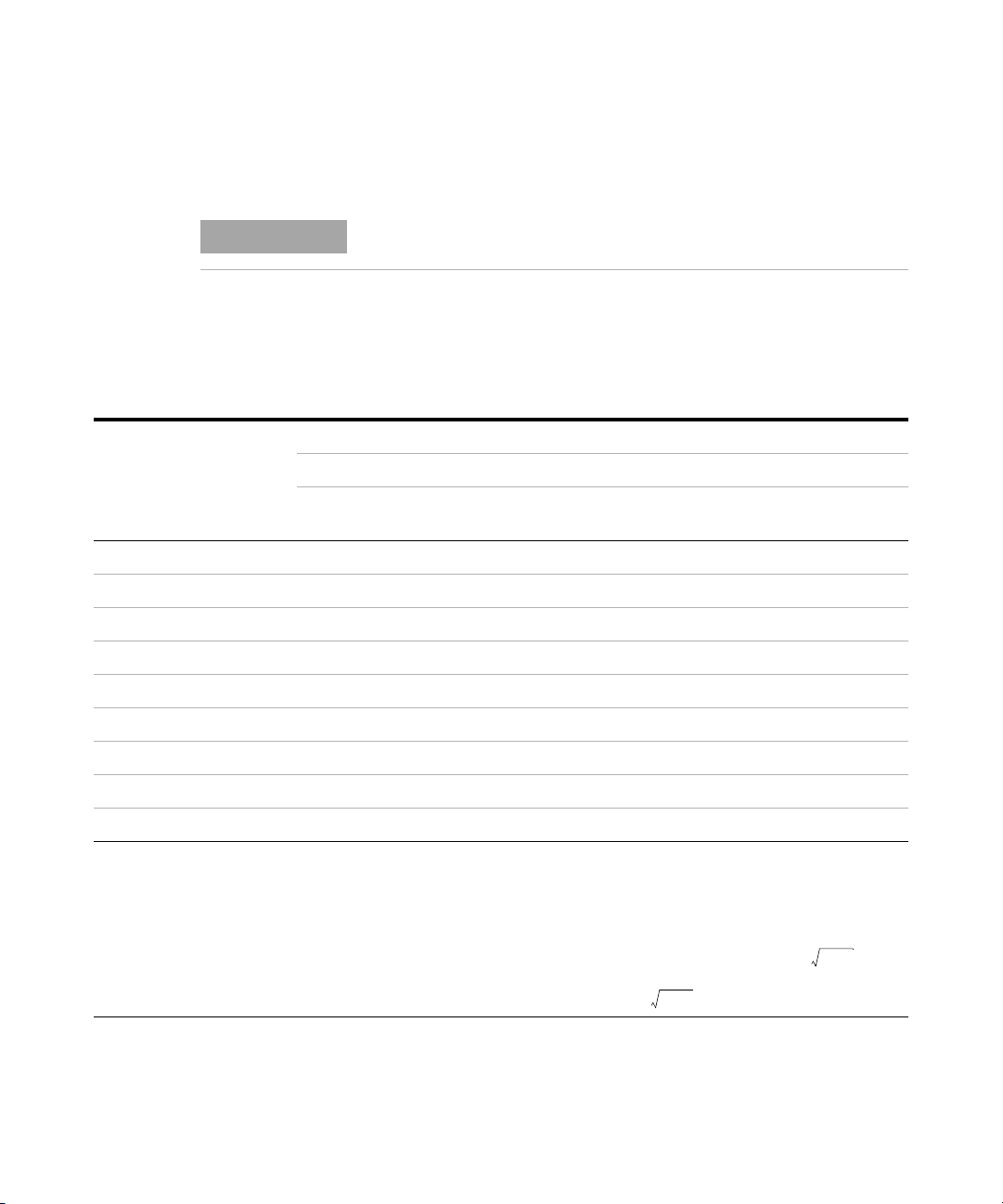
4 Characteristics and Specifications
NOTE
AZOffset+()1 Q2+×
AZOffset+()1 Q2+×
Electrical Specifications
Electrical Specifications
Specification assumptions are given on page 75.
Impedance/Resistance/DCR specifications
Tab l e 4 - 1 Impedance/Resistance/DCR specifications
Accuracy = A
Range Resolution
[1]
2 Ω
[1]
20 Ω
[1]
200 Ω
2000 Ω 0.1 Ω 0.2% + 3 0.2% + 3 0.2% + 3 0.2% + 3 0.2% + 3 0.5% + 5
20 kΩ 0.001 kΩ 0.2% + 3 0.2% + 3 0.2% + 3 0.2% + 3 0.2% + 3 0.5% + 5
200 kΩ 0.01 kΩ 0.5% + 5 0.5% + 5 0.5% + 5 0.5% + 5 0.5% + 5 0.7% + 8
2000 kΩ 0.1 kΩ 0.5% + 5 0.5% + 5 0.5% + 5 0.5% + 5 0.7% + 5 -
[2]
20 MΩ
200 MΩ
Notes:
1 The accuracy for the 2 Ω to 200 Ω range is specified after the Null function is used to subtract the resistance of test leads
and the contact resistance.
2 For the 20 MΩ and 200 MΩ range, the RH is specified for <60%.
3 Resistance measurement is specified to Q <10 and D >0.1; otherwise accuracy is specified as .
4 ESR (Equivalent Series Resistance) measurement is specified according to the impedance measurement and range. The
maximum display is up to 199.99 kΩ and the accuracy is specified as .
0.0001 Ω 0.7% + 50 0.7% + 50 0.7% + 50 0.7% + 50 0.7% + 50 1.0% + 50
0.001 Ω 0.7% + 8 0.7% + 8 0.7% + 8 0.7% + 8 0.7% + 8 0.7% + 8
0.01 Ω 0.2% + 3 0.2% + 3 0.2% + 3 0.2% + 3 0.2% + 3 0.5% + 5
0.001 MΩ 2.0% + 8 2.0% + 8 2.0% + 8 2.0% + 8 5.0% + 8 -
[2]
0.01 MΩ 6.0% + 80 6.0% + 80 6.0% + 80 6.0% + 80 - -
DCR 100 Hz 120 Hz 1 kHz 10 kHz 100 kHz
U1733C only All models All models All models
+ Offset
Z
U1733C and
U1732C only
U1733C only
76 U1731C/U1732C/U1733C User’s Guide
Page 95

Capacitance specifications
Tab l e 4 - 2 Capacitance specifications
Characteristics and Specifications 4
Electrical Specifications
Accuracy = A
Range Resolution
20 mF 0.001 mF 0.5% + 8 0.5% + 8 - - -
2000 μF0.1 μF 0.5% + 5 0.5% + 5 0.5% + 8 - -
200 μF0.01 μF 0.3% + 3 0.3% + 3 0.5% + 5 0.5% + 8 -
20 μF0.001 μF 0.2% + 3 0.2% + 3 0.2% + 3 0.5% + 5 5.0% + 10
2000 nF 0.1 nF 0.2% + 3 0.2% + 3 0.2% + 3 0.2% + 3 0.7% + 10
200 nF 0.01 nF 0.2% + 3 0.2% + 3 0.2% + 3 0.5% + 3 0.7% + 10
20 nF 0.001 nF 0.5% + 5 0.5% + 5 0.2% + 3 0.5% + 3 0.7% + 10
[1]
2000 pF
[1]
200 pF
[1]
20 pF
Notes:
1 The accuracy for the 20 pF to 2000 pF range is specified after the Null function is used to subtract the stray capacitance of
the test leads.
2 The accuracy for the ceramic capacitor will be influenced depending on the dielectric constant (K) of the material used to
make the ceramic capacitor. For related influence factors, please refer to the Component dependency factors section in
the Impedance Measurement Handbook, downloadable for free at http://www.agilent.com/find/lcrmeters.
0.1 pF 0.5% + 10 0.5% + 10 0.5% + 5 0.5% + 3 2.0% + 10
0.01 pF - - 0.5% + 10 0.8% + 10 2.0% + 10
0.001 pF - - - 1.0% + 20 2.5% + 10
100 Hz 120 Hz 1 kHz 10 kHz 100 kHz
All models All models All models
+ Offset
C
U1733C and
U1732C only
U1733C only
U1731C/U1732C/U1733C User’s Guide 77
Page 96

4 Characteristics and Specifications
Electrical Specifications
Inductance specifications
Tab l e 4 - 3 Inductance specifications
Accuracy = A
Range Resolution
20 μH0.001 μH - - - 1.0% + 5 2.5% + 20
200 μH0.01 μH - - 1.0% + 5 0.7% + 3 2.5% + 20
2000 μH0.1 μH 0.7% + 10 0.7% + 10 0.5% + 3 0.5% + 3 0.8% + 20
20 mH 0.001 mH 0.5% + 3 0.5% + 3 0.2% + 3 0.3% + 3 0.8% + 10
200 mH 0.01 mH 0.5% + 3 0.5% + 3 0.2% + 3 0.2% + 3 1.0% + 10
2000 mH 0.1 mH 0.2% + 3 0.2% + 3 0.2% + 3 0.5% + 5 1.0% + 10
20 H 0.001 H 0.2% + 3 0.2% + 3 0.5% + 5 1.0% + 5 2.0% + 10
200 H 0.01 H 0.7% + 5 0.7% + 5 1.0% + 5 2.0% + 8 -
2000 H 0.1 H 1.0% + 5 1.0% + 5 2.0% + 8 - -
100 Hz 120 Hz 1 kHz 10 kHz 100 kHz
All models All models All models
+ Offset
L
U1733C and
U1732C only
U1733C only
78 U1731C/U1732C/U1733C User’s Guide
Page 97

Phase angle of impedance specifications
A
Z
Offset
Z
x
--------------- -+
180
π
-------- -
×
Tab l e 4 - 4 Phase angle of impedance specifications
Characteristics and Specifications 4
Electrical Specifications
Range Resolution Accuracy = θ
–180° to 180° 0.1°/1° D < 1 or Q > 1
Notes:
1 The A
and Offset variables are the accuracy specified at Tab le 4 -1 , “Impedance/Resistance/DCR specifications,” on
Z
page 76.
2 The π variable is rounded up to 3.14159.
Impedance Z
1999.9 Ω 19999 0.2% 3 ±0.12°
199.9 Ω 1999 0.2% 3 ±0.20°
19.9 Ω 199 0.2% 3 ±0.98°
1.9 Ω 19 0.2% 3 ±9.16°
e
X
A
Z
Offset θ
Condition
e
U1731C/U1732C/U1733C User’s Guide 79
Page 98

4 Characteristics and Specifications
A
Z
Offset
Z
x
--------------- -+ 100% 3+×
A
L
Offset
L
x
--------------- -+ 100% 3+×
A
C
Offset
C
x
--------------- -+ 100% 3+×
Electrical Specifications
Dissipation/Quality factor specifications
Tab l e 4 - 5 Dissipation/Quality factor specifications
Range Resolution Accuracy = θ
Z 0.001 to 999 D < 1 or Q > 1
L 0.001 to 999 D < 1 or Q > 1
C 0.001 to 999 D < 1 or Q > 1
Notes:
1 The AZ, AL, AC, and Offset variables are the accuracy specified at Tab l e 4 -1, Ta bl e 4 -2 , and Tab l e 4- 3 respectively.
2 The Z
3 The quality factor is the reciprocal of the dissipation factor.
, Lx, and Cx variables are the display count of the reading. For example, the Cx value is 8888 if the capacitance is
x
88.88 μF for the range of 200 μF.
Capacitance C
88.88 μF 8888 0.2% 3 0.203% + 3
X
A
C
e
Offset D
Condition
e
80 U1731C/U1732C/U1733C User’s Guide
Page 99

Test signal specifications
Tab l e 4 - 6 Test signal specifications
Characteristics and Specifications 4
Electrical Specifications
Selection
100 Hz All models 0.74 Vrms 0.05 Vrms 100 Hz 0.01%
120 Hz All models 0.74 Vrms 0.05 Vrms 120.481 Hz 0.01%
1 kHz All models 0.74 Vrms 0.05 Vrms 1 kHz 0.01%
10 kHz
100 kHz U1733C only 0.70 Vrms 0.05 Vrms 100 kHz 0.01%
DCR U1733C only 1.235 V 0.05 V - -
U1733C and
U1732C only
Test signal level Test frequency
Level Accuracy Frequency Accuracy
0.70 Vrms 0.05 Vrms 10 kHz 0.01%
U1731C/U1732C/U1733C User’s Guide 81
Page 100

4 Characteristics and Specifications
Electrical Specifications
Source impedance of impedance/resistance measurement
Tab l e 4 - 7 Source impedance of impedance/resistance measurement
Typical source impedance
Range
2 Ω 100 Ω 100 Ω 100 Ω 100 Ω 100 Ω 100 Ω
20 Ω 100 Ω 100 Ω 100 Ω 100 Ω 100 Ω 100 Ω
200 Ω 100 Ω 100 Ω 100 Ω 100 Ω 100 Ω 100 Ω
2000 Ω 1 kΩ 1 kΩ 1 kΩ 1 kΩ 1 kΩ 1 kΩ
20 kΩ 10 kΩ 10 kΩ 10 kΩ 10 kΩ 10 kΩ 1 kΩ
200 kΩ 100 kΩ 100 kΩ 100 kΩ 100 kΩ 10 kΩ 1 kΩ
2000 kΩ 100 kΩ 100 kΩ 100 kΩ 100 kΩ
20 MΩ 100 kΩ 100 kΩ 100 kΩ 100 kΩ 100 kΩ -
200 MΩ 100 kΩ 100 kΩ 100 kΩ 100 kΩ --
DCR 100 Hz 120 Hz 1 kHz 10 kHz 100 kHz
U1733C only All models All models All models
U1733C and
U1732C only
10 kΩ -
U1733C only
82 U1731C/U1732C/U1733C User’s Guide
 Loading...