

Page 1

Agilent U1271A/U1272A
Handheld Digital
Multimeter
Service Guide
Agilent Technologies
Page 2

Notices
CAUTION
WARNING
© Agilent Technologies, Inc. 2010
No p art o f this manu al may be re produce d in
any form or by any means (including electronic storage and retrieval or translation
into a foreign language) without prior agreement and written consent from Agilent
Technologies, Inc. as governed by United
States and international copyright laws.
Manual Part Number
U1271-90020
Edition
First Edition, December 27, 2010
Agilent Technologies, Inc.
5301 Stevens Creek Blvd.
Santa Clara, CA 95051 USA
Warranty
The material contained in this document is
provided “as is,” and is subject to change,
without notice, in future editions. Further,
to the maximum extent permitted by the
applicable law, Agilent disclaims all warranties, either express or implied, with
regard to this manual and any information
contained herein, including but not limited
to the implied warranties of merchantability and fitness for a particular purpose.
Agilent shall not be liable for errors or for
incidental or consequential damages in
connection with the furnishing, use, or
performance of this document or of any
information contained herein. Should Agilent and the user have a separate written
agreement with warranty terms covering
the material in this document that conflict
with these terms, the warranty terms in
the separate agreement shall control.
Technology Licenses
The hardware and or software described in
this document are furnished under a license
and may be used or copied only in accordance with the terms of such license.
Restricted Rights Legend
U.S. Government Restricted Rights. Software and technical data rights granted to
the federal government include only those
rights customarily provided to end user customers. Agilent provides this customary
commercial license in Software and technical data pursuant to FAR 12.211 (Technical
Data) and 12.212 (Computer Software) and,
for the Department of Defense, DFARS
252.227-7015 (Technical Data - Commercial
Items) and DFARS 227.7202-3 (Rights in
Commercial Computer Software or Computer Software Documentation).
Safety Notices
A CAUTION notice denotes a hazard. It calls attention to an operating procedure, practice, or the likes
of that, if not correctly performed
or adhered to, could result in damage to the product or loss of important data. Do not proceed beyond a
CAUTION notice until the indicated
conditions are fully understood and
met.
A WARNING notice denotes a
hazard. It calls attention to an
operating procedure, practice, or
the likes of that, if not correctly
performed or adhered to, could
result in personal injury or death.
Do not proceed beyond a WARNING notice until the indicated
conditions are fully understood
and met.
II U1271A/U1272A Service Guide
Page 3
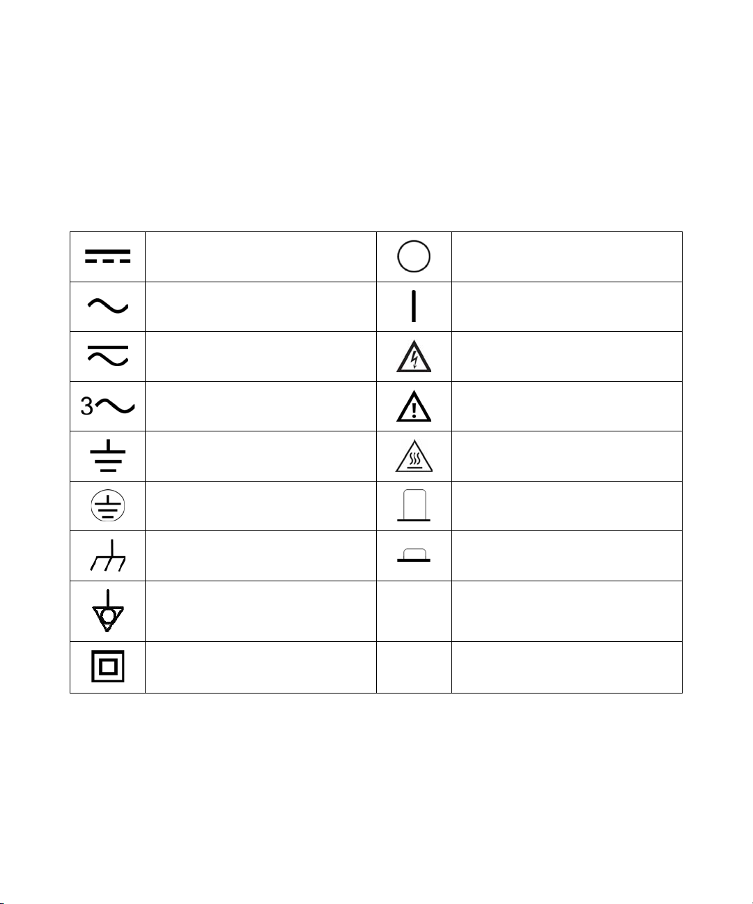
Safety Symbols
CAT III
1000 V
CAT IV
600 V
Direct current (DC) Off (supply)
Alternating current (AC) On (supply)
Both direct and alternating current Caution, risk of electric shock
The following symbols on the instrument and in the documentation
indicate precautions which must be taken to maintain safe operation of
the instrument.
Three-phase alternating current
Earth (ground) terminal Caution, hot surface
Protective conductor terminal Out position of a bi-stable push control
Frame or chassis terminal In position of a bi-stable push control
Equipotentiality Category III 1000 V overvoltage protection
Equipment protected throughout by
double insulation or reinforced
insulation
Caution, risk of danger (refer to this manual
for specific Warning or Caution information)
Category IV 600 V overvoltage protection
U1271A/U1272A Service Guide III
Page 4

Safety Considerations
CAUTION
WARNING
Read the information below before using this multimeter. The descriptions
and instructions in this manual apply to the Agilent U1271A and U1272A
Handheld Digital Multimeters (hereafter referred to as the multimeter).
The model U1272A appears in all illustrations.
• Disconnect circuit power and discharge all high-voltage capacitors
before testing resistance, continuity, diodes, or capacitance.
• Use the proper terminals, function, and range for your
measurements.
• This device is for use at altitudes of up to 2,000 m.
• Never measure voltage when current measurement is selected.
• Always use the specified battery type.
• Do not use the multimeter if it is damaged. Before you use the
multimeter, inspect the case. Look for cracks or missing plastic.
Pay particular attention to the insulation surrounding the
connectors.
• Inspect the test leads for damaged insulation or exposed metal.
Check the test leads for continuity. Replace damaged test leads
before you use the multimeter.
IV U1271A/U1272A Service Guide
• Do not operate the multimeter around explosive gas, vapor, or wet
environments.
• Do not apply more than the rated voltage (as marked on the
multimeter) between terminals, or between terminal and earth
ground.
• Never use the multimeter in wet conditions or when there is
water on the surface. If the multimeter is wet, ensure that the
multimeter is dried only by trained personnel.
• Before use, verify the multimeter's operation by measuring a
known voltage.
Page 5

WARNING
• When measuring current, turn off the circuit power before
connecting the multimeter in the circuit. Remember to place the
multimeter in series with the circuit.
• When servicing the multimeter, use only the specified
replacement parts.
• Use caution when working above 60 V DC, 30 V AC RMS, or 42.4 V
peak. Such voltages pose a shock hazard.
• Be aware of the presence of hazardous voltage before using the
Low Pass Filter (LPF) function for voltage measurement. Voltages
measured are usually greater than what indicated on the
multimeter as the voltages with higher frequencies have been
filtered through the LPF function.
• Do not use the Z
(low input impedance) function (U1272A
LOW
only) to measure voltages in circuits that could be damaged by
this function’s low input impedance of 2 k
Ω.
• When using the probes, keep your fingers behind the finger
guards on the probes.
• Connect the common test lead before you connect the live test
lead. When you disconnect the leads, disconnect the live test lead
first.
• Remove the test leads from the multimeter before you open the
battery cover.
• Do not operate the multimeter with the battery cover or portions
of the cover removed or loosened.
• To avoid false readings, which may lead to possible electric shock
or personal injury, replace the battery as soon as the low battery
indicator appears and flashes.
U1271A/U1272A Service Guide V
Page 6

Environmental Conditions
NOTE
This instrument is designed for indoor use and in an area with low
condensation. The table below shows the general environmental
requirements for this instrument.
Environmental conditions Requirements
Operating temperature Full accuracy from –20 °C to 55 °C
Full accuracy up to 80% RH (relative
Operating humidity
Storage temperature –40 °C to 70 °C
Altitude Up to 2000 meters
Pollution degree Pollution degree II
The U1271A/U1272A Handheld Digital Multimeter complies with the following
safety and EMC requirements:
• EN/IEC 61010-1:2001
• ANSI/UL 61010-1:2004
• CAN/CSA-C22.2 No. 61010-1-04
• Commercial limits compliance with EN61326-1
humidity) for temperature up to 30 °C,
decreasing linearly to 50% RH at 55 °C
VI U1271A/U1272A Service Guide
Page 7
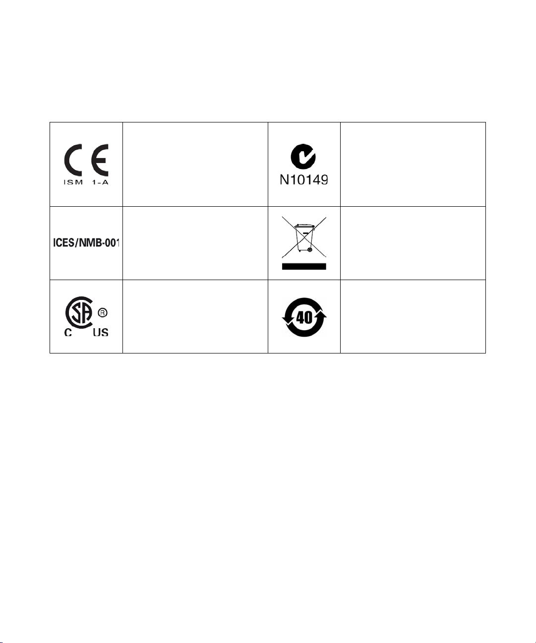
Regulatory Markings
The CE mark is a registered trademark
of the European Community. This CE
mark shows that the product complies
with all the relevant European Legal
Directives.
The C-tick mark is a registered
trademark of the Spectrum
Management Agency of Australia. This
signifies compliance with
the Australia EMC Framework
regulations under the terms of the
Radio Communication Act of 1992.
ICES/NMB-001 indicates that this ISM
device complies with the Canadian
ICES-001.
Cet appareil ISM est confomre a la
norme NMB-001 du Canada.
The CSA mark is a registered
trademark of the Canadian Standards
Association.
This instrument complies with the
WEEE Directive (2002/96/EC) marking
requirement. This affixed product label
indicates that you must not discard
this electrical or electronic product in
domestic household waste.
This symbol indicates the time period
during which no hazardous or toxic
substance elements are expected to
leak or deteriorate during normal use.
Forty years is the expected useful life
of the product.
U1271A/U1272A Service Guide VII
Page 8
Waste Electrical and Electronic Equipment (WEEE) Directive 2002/96/EC
This instrument complies with the WEEE Directive (2002/96/EC) marking
requirement. This affixed product label indicates that you must not discard
this electrical or electronic product in domestic household waste.
Product Category:
With reference to the equipment types in the WEEE directive Annex 1, this
instrument is classified as a “Monitoring and Control Instrument” product.
The affixed product label is as shown below.
Do not dispose in domestic household waste.
To return this unwanted instrument, contact your nearest Agilent Service
Centre, or visit
www.agilent.com/environment/product
for more information.
VIII U1271A/U1272A Service Guide
Page 9

Declaration of Conformity (DoC)
NOTE
The Declaration of Conformity (DoC) for this instrument is available on the
Agilent Web site. You can search the DoC by its product model or
description at the Web address below.
http://regulations.corporate.agilent.com/DoC/search.htm
If you are unable to search for the respective DoC, please contact your
local Agilent representative.
U1271A/U1272A Service Guide IX
Page 10

THIS PAGE HAS BEEN INTENTIONALLY LEFT BLANK.
X U1271A/U1272A Service Guide
Page 11

Table of Contents
1 Calibration Procedures
Agilent Calibration Services 2
Closed case calibration 2
Calibration interval 2
Other recommendations for calibration 3
Recommended Test Equipment 4
Basic Operating Test 5
Backlight test 5
Display test 5
Current terminal input test 6
Calibration Process 8
Test considerations 8
Input connections 9
Performance Verification Tests 10
Calibration Security 18
Unsecuring the Instrument for Calibration 19
To unsecure the instrument from the front panel 19
To change the calibration security code 20
To reset the calibration security code to its factory default 21
Using the Front Panel for Adjustments 23
Adjustment considerations 23
Valid adjustment input values 24
Adjustment procedure 27
Exiting the adjustment mode 29
Calibration Count 30
Calibration Error Codes 31
U1271A/U1272A Service Guide XI
Page 12

2 Service and Maintenance
Troubleshooting 34
Verifying the Fuse Health 35
Fuse Replacement 38
Returning the Instrument for Service 42
Replaceable Parts 43
To order replaceable parts 43
Types of Service Available 44
Extended service contracts 44
Obtaining Repair Service (Worldwide) 45
XII U1271A/U1272A Service Guide
Page 13

List of Figures
Figure 1-1 LCD display screen 5
Figure 1-2 A-Err display 6
Figure 1-3
Figure 1-4 SECUr display 19
Figure 1-5 Calibration security code operation 20
Figure 1-6 SECUr display 21
Figure 1-7 SEr.no display 22
Figure 1-8 rEF display 23
Figure 1-9 rEF display 28
Figure 2-1 Testing Fuse 1 36
Figure 2-2 Testing Fuse 2 37
Figure 2-3 Replacing Fuse 1 39
Figure 2-4 Replacing Fuse 2 40
Figure 2-5 Positions of Fuse 1 and Fuse 2 41
μA-Err display 7
U1271A/U1272A Service Guide XIII
Page 14

THIS PAGE HAS BEEN INTENTIONALLY LEFT BLANK.
XIV U1271A/U1272A Service Guide
Page 15

List of Tables
Tab le 1- 1 Recommended test equipment 4
Tab le 1- 2 Performance verification tests 10
Tab le 1- 3 Adjustment input values 24
Tab le 1- 4 Calibration error codes 31
Tab le 2- 1 Operating checklist 34
Tab le 2- 2 Fuse displayed readings 35
U1271A/U1272A Service Guide XV
Page 16

THIS PAGE HAS BEEN INTENTIONALLY LEFT BLANK.
XVI U1271A/U1272A Service Guide
Page 17

U1271A/U1272A Handheld Digital Multimeter
Service Guide
1
Calibration Procedures
Agilent Calibration Services 2
Closed case calibration 2
Calibration interval 2
Other recommendations for calibration 3
Recommended Test Equipment 4
Basic Operating Test 5
Backlight test 5
Display test 5
Current terminal input test 6
Calibration Process 8
Test considerations 8
Input connections 9
Performance Verification Tests 10
Calibration Security 18
Unsecuring the Instrument for Calibration 19
To unsecure the instrument from the front panel 19
To change the calibration security code 20
To reset the calibration security code to its factory default 21
Using the Front Panel for Adjustments 23
Adjustment considerations 23
Valid adjustment input values 24
Adjustment procedure 27
Exiting the adjustment mode 29
Calibration Count 30
Calibration Error Codes 31
This chapter contains procedures for verifying the
instrument performance, as well as procedures for making
adjustments (calibration) where necessary.
Agilent Technologies
1
Page 18

1 Calibration Procedures
Agilent Calibration Services
Agilent Calibration Services
Agilent Technologies offers calibration services at competitive
prices. When your instrument is due for calibration, contact
your local Agilent Service Center for recalibration. See
“Types of Service Available” on page 44 for more
information on the various calibration services offered.
Closed case calibration
The U1271A and U1272A handheld digital multimeter
features closed- case electronic calibration. In other words,
no internal electro- mechanical adjustment is required. This
instrument calculates correction factors based on the input
reference signals you feed into it during the calibration
process. The new correction factors are stored in nonvolatile
EEPROM memory until the next calibration (adjustment) is
performed.
The contents of this nonvolatile EEPROM memory will not
change even when the power is switched off.
Calibration interval
The instrument should be calibrated on a regular interval
determined by the measurement accuracy requirements of
your application.
A one- year interval is adequate for most applications.
Accuracy specifications are warranted only if calibration is
performed at regular intervals. Accuracy specifications are
not warranted beyond the one- year calibration interval.
Agilent does not recommend extending calibration intervals
beyond two years for any application.
2 U1271A/U1272A Service Guide
Page 19

Other recommendations for calibration
Specifications are only guaranteed within the specified
period from the last calibration. Agilent recommends that
readjustment should always be performed at whatever
calibration interval you select. This will ensure that the
instrument remains within its specifications until the next
calibration. This calibration criterion provides the best
long- term stability.
During performance verification tests, only the performance
data is collected; these tests do not guarantee that the
instrument will remain within the specified limits. The tests
are only for identifying which functions need adjustment.
Please refer to the “Calibration Count” on page 30 and
verify that all adjustments have been performed.
Calibration Procedures 1
Agilent Calibration Services
U1271A/U1272A Service Guide 3
Page 20

1 Calibration Procedures
Recommended Test Equipment
Recommended Test Equipment
The test equipment recommended for the performance
verification and adjustment procedures is listed below in
Table 1- 1. If the exact instrument is not available, substitute
with another calibration standard of equivalent accuracy.
Tab l e 1 - 1 Recommended test equipment
Application
DC voltage Fluke 5520A
DC current Fluke 5520A
Resistance Fluke 5520A
AC voltage Fluke 5520A
AC current Fluke 5520A
Frequency Fluke 5520A
Capacitance Fluke 5520A
Duty cycle Fluke 5520A
Diode Fluke 5520A
Recommended
equipment
Recommended accuracy requirements
<20% of the U1271A/U1272A accuracy
specification
<20% of the U1271A/U1272A accuracy
specification
<20% of the U1271A/U1272A accuracy
specification
<20% of the U1271A/U1272A accuracy
specification
<20% of the U1271A/U1272A accuracy
specification
<20% of the U1271A/U1272A accuracy
specification
<20% of the U1271A/U1272A accuracy
specification
<20% of the U1271A/U1272A accuracy
specification
<20% of the U1271A/U1272A accuracy
specification
Temperature Fluke 5520A
Short
Shorting plug — a dual banana plug with a copper wire
shorting the two terminals
<20% of the U1271A/U1272A accuracy
specification
4 U1271A/U1272A Service Guide
Page 21

Basic Operating Test
Setup
A
u
t
o
T
r
i
g
H
o
l
d
Backlight test
Calibration Procedures 1
Basic Operating Test
The tests listed below are used to test the basic operability
of the instrument. Repair is required if the instrument fails
the any of the tests.
• “Backlight test”
• “Display test”
• “Current terminal input test”
Press and hold the button while turning the rotary
switch to any other position (OFF to ON). Check that the
multimeter’s backlight is turned on. Press any key to exit
this mode.
Display test
Press and hold the button while turning the rotary
switch to any other position (OFF to ON). Check that all the
annunciators are displayed in the LCD. Compare the display
with the example shown in Figure 1- 1. Press any key to exit
this mode.
Figure 1-1 LCD display screen
U1271A/U1272A Service Guide 5
Page 22

1 Calibration Procedures
NOTE
Basic Operating Test
Current terminal input test
This test determines if the input warnings of the current
terminals are functioning properly.
A-Err test
The multimeter sounds a continuous alert beep when the
test lead is inserted into the terminal but the rotary
switch is not set to the function. The secondary display
will indicate , as shown in Figure 1- 2.
Figure 1-2 A-Err display
The alert beep tone will continue to beep until the test lead
is removed from the terminal or until the rotary switch is
set to the function.
Before conducting this test, ensure that the beep function is not disabled
in the multimeter’s Setup.
μA-Err test
The multimeter sounds a continuous alert beep when the
test lead is inserted into the terminal but the rotary
switch is not set to the function. The secondary display
will indicate , as shown in Figure 1- 3.
6 U1271A/U1272A Service Guide
Page 23

Calibration Procedures 1
NOTE
Basic Operating Test
Figure 1-3 μA-Err display
The alert beep tone will continue to beep until the test lead
is removed from the terminal or until the rotary
switch is set to the function.
Before conducting this test, ensure that the beep function is not disabled
in the multimeter’s Setup.
U1271A/U1272A Service Guide 7
Page 24

1 Calibration Procedures
Calibration Process
Calibration Process
1 Prior to performing the verification tests, see the “Test
considerations” on page 8.
2 Perform the verification tests to characterize the
multimeter; see “Performance Verification Tests” on
page 10.
3 Unsecure the multimeter for calibration; see “Calibration
Security” on page 18.
4 Prior to performing the adjustments, see the “Adjustment
considerations” on page 23.
5 Perform the adjustment procedure; see “Adjustment
procedure” on page 27.
6 Secure the multimeter against unauthorized calibration;
see “Exiting the adjustment mode” on page 29. Ensure
that the multimeter has quit the adjustment mode and is
turned off.
7 Record the new security code and calibration count in the
multimeter's maintenance records.
Test considerations
For optimum performance, all procedures should comply
with the following recommendations:
• The performance verification test or adjustment should be
performed under laboratory condition which ambient
temperature can be controlled.
• Ensure that the calibration ambient temperature is stable
and is between 18 °C and 28 °C. Ideally the calibration
should be performed at 23 °C ± 1 °C.
• Ensure that the ambient relative humidity is less than
80%.
• The instrument should be put under the laboratory
environment for at least 1 hour.
• Allow a warm- up period of 3 minutes.
8 U1271A/U1272A Service Guide
Page 25

• Use shielded twisted pair Teflon- insulated cables to
reduce settling and noise errors. Keep the input cables as
short as possible. Long test leads can also act as antennas
which may pick up AC signals.
• Connect the input cable shields to earth ground.
Please ensure that the calibration standards and test
procedures used do not introduce additional errors. Ideally,
the standards used to verify and adjust the instrument
should be of an order of magnitude more accurate than each
instrument range full- scale error specification.
Input connections
Test connections to the instrument are best accomplished
using the dual banana plug with a copper wire short
between the two terminals for low- thermal offset
measurement.
We recommend the use of shielded, twisted- pair, Teflon
interconnect cables of minimum length between the
calibrator and the multimeter. The cable shields should be
earth ground referenced. This configuration is recommended
to attain optimal noises and settling time performance
during calibration.
Calibration Procedures 1
Calibration Process
U1271A/U1272A Service Guide 9
Page 26

1 Calibration Procedures
NOTE
Qik-V
Z
LOW
Performance Verification Tests
Performance Verification Tests
Use the performance verification tests to verify the
measurement performance of the instrument. The
performance verification tests use the instrument's
specifications listed in the U1271A/U1272A User's Guide
(available for download at www.agilent.com/find/hhTechLib).
The performance verification tests are recommended as
acceptance tests when you first receive the instrument. The
acceptance test results should be compared against the one
year test limits. After acceptance, you should repeat the
performance verification tests at every calibration interval.
If the multimeter fails the performance verification tests,
adjustment or repair is required.
Ensure that you have read the “Test considerations” on page 8 before
running the performance verification tests.
Tab l e 1 - 2 Functional Test
Step Test function Range 5520 output
Qik-V Turn the rotary switch to
the position.
Z
Turn the rotary switch
LOW
to the position.
1000 V 1000 V ±20 V N/A
1000 V, 70 Hz ±250 V N/A
1000 V 3 V N/A ±2.03 V
3 V, 70 Hz N/A ±4.03 V
Error from nominal 1 year
U1271A U1272A
10 U1271A/U1272A Service Guide
Page 27

Tab l e 1 - 2 Functional Test
Calibration Procedures 1
Performance Verification Tests
Step Test function Range 5520 output
1
ACV Turn the rotary switch to
the position.
3 V 3 V, 20 Hz N/A ±0.0325 V
3 V, 45 Hz ±0.0230 V ±0.0200 V
3 V, 65 Hz ±0.0230 V ±0.0200 V
3 V, 1 kHz ±0.0325 V ±0.0325 V
3 V, 5 kHz ±0.0625 V ±0.0475 V
3 V, 20 kHz ±0.0640 V ±0.0640 V
2.7 V, 100 kHz N/A ±0.0985 V
30 V 30 V, 20 Hz N/A ±0.325 V
30 V, 45 Hz ±0.230 V ±0.200 V
30 V, 65 Hz ±0.230 V ±0.200 V
30 V, 1 kHz ±0.325 V ±0.325 V
30 V, 5 kHz ±0.625 V ±0.475 V
30 V, 20 kHz ±0.640 V ±0.640 V
27 V, 100 kHz N/A ±0.985 V
300 V 300 V, 45 Hz ±2.30 V ±2.00 V
Error from nominal 1 year
U1271A U1272A
300 V, 65 Hz ±2.30 V ±2.00 V
300 V, 1 kHz ±3.25 V ±3.25 V
300 V, 5 kHz ±6.25 V ±4.75 V
270 V, 20 kHz N/A ±5.80 V
1000 V 1000 V, 45 Hz ±9.0 V ±8.0 V
1000 V, 65 Hz ±9.0 V ±8.0 V
1000 V, 1 kHz ±12.5 V ±12.5 V
1000 V, 5 kHz N/A ±17.5 V
U1271A/U1272A Service Guide 11
Page 28

1 Calibration Procedures
S
h
i
f
t
V
i
e
w
E
s
c
H
z
%
m
s
L
o
g
H
z
%
m
s
L
o
g
Performance Verification Tests
Tab l e 1 - 2 Functional Test
Step Test function Range 5520 output
LPF While the rotary switch is
in the position, press the
key once.
3 V 3 V, 20 Hz N/A ±0.0325 V
3 V, 45 Hz ±0.0230 V ±0.0200 V
3 V, 65 Hz ±0.0230 V ±0.0200 V
2
Frequency While the rotary
9.999 kHz 1.0000 kHz, 0.096 V ±0.005 kHz ±0.005 kHz
2.7 V, 430 Hz ±0.1375 V ±0.1375 V
switch is in the position,
press the key once.
3
Duty cycle While the rotary
switch is in the position,
99.99% 50%, 100 Hz,
3 Vpp square wave
press the key twice.
4
ACmV Turn the rotary switch
to the position.
30 mV 30 mV, 20 Hz N/A ±0.235 mV
30 mV, 45 Hz N/A ±0.200 mV
30 mV, 65 Hz N/A ±0.200 mV
30 mV, 1 kHz N/A ±0.235 mV
30 mV, 5 kHz N/A ±0.325 mV
30 mV, 20 kHz N/A ±0.340 mV
Error from nominal 1 year
U1271A U1272A
±0.3% ±0.3%
30 mV, 100 kHz N/A ±1.090 mV
300 mV 300 mV, 20 Hz N/A ±2.35 mV
300 mV, 45 Hz ±2.30 mV ±2.00 mV
300 mV, 65 Hz ±2.30 mV ±2.00 mV
300 mV, 1 kHz ±3.25 mV ±2.35 mV
300 mV, 5 kHz ±6.25 mV ±3.25 mV
300 mV, 20 kHz ±6.40 mV ±3.40 mV
300 mV, 100 kHz N/A ±10.90 mV
12 U1271A/U1272A Service Guide
Page 29

Tab l e 1 - 2 Functional Test
S
h
i
f
t
V
i
e
w
E
s
c
Calibration Procedures 1
Performance Verification Tests
Step Test function Range 5520 output
5
DCV Turn the rotary switch to
the / position.
3 V 3 V ±0.0020 V ±0.0020 V
30 V 30 V ±0.017 V ±0.017 V
300 V 300 V ±0.17 V ±0.17 V
1000 V 1000 V ±0.7 V ±0.7 V
6
AC+DCV Turn the rotary
switch to the position, and
press the key twice.
3 V 3 V, 20 Hz N/A ±0.0360 V
3 V, 45 Hz N/A ±0.0235 V
3 V, 65 Hz N/A ±0.0235 V
30 V 30 V, 20 Hz N/A ±0.360 V
3 V, 1 kHz N/A ±0.0360 V
3 V, 5 kHz N/A ±0.0510 V
3 V, 20 kHz N/A ±0.0675 V
2.7 V, 100 kHz N/A ±0.1017 V
30 V, 45 Hz N/A ±0.235 V
30 V, 65 Hz N/A ±0.235 V
Error from nominal 1 year
U1271A U1272A
300 V 300 V, 45 Hz N/A ±2.35 V
30 V, 1 kHz N/A ±0.360 V
30 V, 5 kHz N/A ±0.510 V
30 V, 20 kHz N/A ±0.675 V
27 V, 100 kHz N/A ±1.017 V
300 V, 65 Hz N/A ±2.35 V
300 V, 1 kHz N/A ±3.60 V
300 V, 5 kHz N/A ±5.10 V
270 V, 20 kHz N/A ±6.12 V
U1271A/U1272A Service Guide 13
Page 30

1 Calibration Procedures
S
h
i
f
t
V
i
e
w
E
s
c
Performance Verification Tests
Tab l e 1 - 2 Functional Test
Step Test function Range 5520 output
Error from nominal 1 year
U1271A U1272A
1000 V 1000 V, 45 Hz N/A ±9.5 V
1000 V, 65 Hz N/A ±9.5 V
1000 V, 1 kHz N/A ±14.0 V
1000 V, 5 kHz N/A ±19.0 V
7
[1]
DCmV
Turn the rotary
switch to the / position.
30 mV 30 mV N/A ±0.035 mV
–30 mV N/A ±0.035 mV
300 mV 300 mV ±0.20 mV ±0.20 mV
–300 mV ±0.10 mV ±0.10 mV
[1] The accuracy is specified after the Null function is used to subtract the thermal effect (by shorting the test leads) before
measuring the signal.
8
AC+DCmV Turn the rotary
switch to the position, and
press the key twice.
30 mV 30 mV, 20 Hz N/A ±0.235 mV
30 mV, 45 Hz N/A ±0.200 mV
30 mV, 65 Hz N/A ±0.200 mV
30 mV, 1 kHz N/A ±0.235 mV
30 mV, 5 kHz N/A ±0.325 mV
300 mV 300 mV, 20 Hz N/A ±2.35 mV
30 mV, 20 kHz N/A ±0.340 mV
30 mV, 100 kHz N/A ±1.090 mV
300 mV, 45 Hz N/A ±2.00 mV
300 mV, 65 Hz N/A ±2.00 mV
300 mV, 1 kHz N/A ±2.35 mV
300 mV, 5 kHz N/A ±3.25 mV
300 mV, 20 kHz N/A ±3.40 mV
300 mV, 100 kHz N/A ±10.90 mV
14 U1271A/U1272A Service Guide
Page 31

Tab l e 1 - 2 Functional Test
Smart
S
c
a
l
e
N
u
l
l
Auto
Calibration Procedures 1
Performance Verification Tests
Step Test function Range 5520 output
Error from nominal 1 year
U1271A U1272A
9
Resistance Turn the rotary
switch to the / position.
30 Ω
300 Ω
3 kΩ
[2]
[2]
[2]
30 Ω N/A ±0.070 Ω
300 Ω ±0.65 Ω ±0.65 Ω
3 kΩ ±0.0065 kΩ ±0.0065 kΩ
30 kΩ 30 kΩ ±0.065 kΩ ±0.065 kΩ
300 kΩ 300 kΩ ±1.55 kΩ ±0.65 kΩ
3 MΩ 3 MΩ ±0.0185 MΩ ±0.0185 MΩ
30 MΩ
100 MΩ
300 MΩ
[3]
[3]
[3]
30 MΩ ±0.365 MΩ ±0.365 MΩ
100 MΩ ±2.10 MΩ N/A
120 MΩ N/A ±9.70 MΩ
[2] The accuracy of the 300 Ω to 3 kΩ range is specified after the Null function is used to subtract the test lead resistance
and thermal effect (by shorting the test leads). Apply a 0 Ω calibrator output and allow the multimeter to settle before
press the button.
[3] The RH is specified for <60%.
10
Diode Turn the rotary switch
3 V 3 V 0.0155 V 0.0155 V
to the / position.
11
Capacitance Turn the rotary
switch to the position.
10 nF 10 nF ±0.105 nF ±0.105 nF
100 nF 100 nF ±1.02 nF ±1.02 nF
1000 nF 1000 nF ±10.2 nF ±10.2 nF
10 μF10 μF ±0.102 μF ±0.102 μF
100 μF100 μF ±1.02 μF ±1.02 μF
1000 μF 1000 μF±10.2 μF±10.2 μF
10 mF 10 mF ±0.102 mF ±0.102 mF
U1271A/U1272A Service Guide 15
Page 32

1 Calibration Procedures
S
h
i
f
t
V
i
e
w
E
s
c
S
h
i
f
t
V
i
e
w
E
s
c
Performance Verification Tests
Tab l e 1 - 2 Functional Test
Step Test function Range 5520 output
Error from nominal 1 year
U1271A U1272A
12
Te m pe r a tu r e
rotary switch is in the
position, press the key
once.
[4]
While the
–200 °C to 1372 °C –200 °C ± 3.0 °C ± 3.0 °C
0 °C ±1.0 °C ±1.0 °C
1372 °C ±14.7 °C ±14.7 °C
[4] Ensure that the ambient temperature is stable within ±1 ºC. Ensure that the multimeter is placed in a controlled
environment for at least 1 hour before you proceed to ensure that the multimeter’s internal reference junction sensor and
input terminal are stabilized at the same environment. Keep the multimeter away from any ventilation exit.
Differences in ambient compensation between the calibrator and multimeter may cause some deviations shown between
the readings of the calibrator and multimeter. Placing the multimeter close to the output terminal of the calibrator will help
reduce this deviation.
Keep the thermocouple test lead as close to the multimeter as possible.
Do not touch the thermocouple test lead after connecting it to the calibrator. Allow the connection to stabilize for at least
another 15 minutes before performing the measurement.
13
DCμA Turn the rotary switch
to the position.
14
ACμA While the rotary switch
is in the position, press the
key once.
300 μA300 μA ±0.65 μA ±0.63 μA
3000 μA 3000 μA ±6.5 μA ±6.3 μA
300 μA300 μA, 20 Hz N/A ±2.95 μA
300 μA, 45 Hz ±2.95 μA ±2.05 μA
300 μA, 65 Hz ±2.95 μA ±2.05 μA
300 μA, 1 kHz ±2.95 μA ±2.95 μA
3000 μA 3000 μA, 20 Hz N/A ±29.5 μA
3000 μA, 45 Hz ±29.5 μA±20.5 μA
3000 μA, 65 Hz ±29.5 μA±20.5 μA
3000 μA, 1 kHz ±29.5 μA±29.5 μA
15
DCmA Turn the rotary switch
to the position.
30 mA 30 mA ±0.065 mA ±0.063 mA
300 mA 300 mA ±0.65 mA ±0.63 mA
16 U1271A/U1272A Service Guide
Page 33

Tab l e 1 - 2 Functional Test
S
h
i
f
t
V
i
e
w
E
s
c
S
h
i
f
t
V
i
e
w
E
s
c
Calibration Procedures 1
Performance Verification Tests
Step Test function Range 5520 output
Error from nominal 1 year
U1271A U1272A
16
ACmA While the rotary
switch is in the position,
press the key once.
30 mA 30 mA, 20 Hz N/A ±0.295 mA
30 mA, 45 Hz ±0.295 mA ±0.205 mA
30 mA, 65 Hz ±0.295 mA ±0.205 mA
17
DCA
to the position.
[5]
Turn the rotary switch
300 mA 300 mA, 20 Hz N/A ±2.95 mA
3 A 3 A ±0.0100 A ±0.0100 A
10 A 10 A ±0.04 A ±0.04 A
30 mA, 1 kHz ±0.295 mA ±0.295 mA
300 mA, 45 Hz ±2.95 mA ±2.05 mA
300 mA, 65 Hz ±2.95 mA ±2.05 mA
300 mA, 1 kHz ±2.95 mA ±2.95 mA
[5] CAUTION: Connect the calibrator to the multimeter's A and COM terminals before applying the 3 A and 10 A input.
18
ACA While the rotary switch
is in the position, press the
key once.
3 A 3 A, 45 Hz ±0.0325 A ±0.0325 A
3 A, 65 Hz ±0.0325 A ±0.0325 A
3 A, 1 kHz ±0.0325 A ±0.0325 A
10 A 10 A, 45 Hz ±0.125 A ±0.125 A
10 A, 65 Hz ±0.125 A ±0.125 A
10 A, 1 kHz ±0.125 A ±0.125 A
U1271A/U1272A Service Guide 17
Page 34

1 Calibration Procedures
NOTE
Calibration Security
Calibration Security
The calibration security code prevents accidental or
unauthorized adjustments to the instrument. When you first
receive your instrument, it is secured. Before you can adjust
the instrument, you must unsecure it by entering the correct
security code (see “Unsecuring the Instrument for
Calibration” on page 19).
The security code can only be changed after the instrument has been
unsecured. You can unsecure the instrument from its front panel.
The security code is set to “1234” when the instrument is
shipped from the factory. The security code is stored in
nonvolatile memory, and does not change when power has
been turned off.
The security code may contain up to 4 numeric characters.
18 U1271A/U1272A Service Guide
Page 35

Unsecuring the Instrument for Calibration
NOTE
S
h
i
f
t
V
i
e
w
E
s
c
A
u
t
o
T
r
i
g
H
o
l
d
P
e
a
k
M
a
x
M
i
n
A
u
t
o
Ra
n
g
e
Exit
Dual
Setup
H
z
%
m
s
L
o
g
Unsecuring the Instrument for Calibration
Before you can adjust the instrument, you must unsecure it
by entering the correct security code.
The default security code is set to 1234.
If you forget your security code, see “To reset the calibration security code
to its factory default” on page 21.
To unsecure the instrument from the front panel
1 Power- on the multimeter and press the and
keys simultaneously for more that 1 second to enter the
calibration security code entry mode.
2 is shown in the secondary display while the
security code is shown in the primary display.
Calibration Procedures 1
Figure 1-4 SECUr display
3 Press or to move the cursor to the right or
to the left.
4 Press or to increment or decrement the digit.
5 Press when you are done.
If the correct security code is entered, is shown in
the secondary display briefly, after which the instrument
will enter the adjustment mode.
U1271A/U1272A Service Guide 19
Page 36

1 Calibration Procedures
Wrong security code entered
Correct security code entered,
multimeter enters adjustment mode
Press
H
z
%
m
s
L
o
g
Press
H
z
%
m
s
L
o
g
A
u
t
o
T
r
i
g
H
o
l
d
Unsecuring the Instrument for Calibration
If the incorrect security code is entered, an error code
will appear at the secondary display briefly, after which
the calibration security code entry mode will appear
again.
Figure 1-5 Calibration security code operation
To change the calibration security code
1 After the instrument has been unsecured, press for
more than 1 second to enter the calibration security code
setting mode.
2 The factory default calibration security code “1234” will
be displayed on the primary display.
20 U1271A/U1272A Service Guide
Page 37

Calibration Procedures 1
P
e
a
k
M
a
x
M
i
n
A
u
t
o
R
a
n
g
e
Exit
Dual
Setup
H
z
%
m
s
L
o
g
NOTE
Unsecuring the Instrument for Calibration
Figure 1-6 SECUr display
3 Set your new calibration security code.
Press or to move the cursor to the right or
to the left.
Press or to increment or decrement the digit.
4 Press to save the new calibration security code.
5 If the new calibration security code has been successfully
stored, the secondary display will show . Record
down your new calibration security code and store it in a
safe location.
To reset the calibration security code to its factory default
If you have forgotten the correct calibration security code,
you may follow the steps below to reset the calibration
security code to the factory default code (1234).
If you do not have a record (or have lost the record) of the security code,
first try the factory default code, “1234” from the front panel.
U1271A/U1272A Service Guide 21
Page 38

1 Calibration Procedures
S
h
i
f
t
V
i
e
w
E
s
c
A
u
t
o
T
r
i
g
H
o
l
d
S
h
i
f
t
V
i
e
w
E
s
c
P
e
a
k
M
a
x
M
i
n
A
u
t
o
R
a
n
g
e
Exit
Dual
Setup
H
z
%
m
s
L
o
g
Unsecuring the Instrument for Calibration
1 Before you begin, note down the last four digits of the
multimeter's serial number (located at the bottom of the
multimeter’s rear panel).
2 Power- on the multimeter and press the and
keys simultaneously for more that 1 second to enter the
calibration security code entry mode.
3 is shown in the secondary display while the
security code is shown in the primary display.
4 Press for more than 1 second to enter the
calibration security code reset mode. The secondary
display shows .
Figure 1-7 SEr.no display
5 Set the code to the same as the last four digits of the
instrument's serial number.
Press or to move the cursor to the right or
to the left.
Press or to increment or decrement the digit.
6 Press to confirm the entry.
7 If the four digits entered are correct, the secondary
display will show . The calibration security code is
now set to the its factory default code, 1234.
If you want to enter a new security code, see “To change the
calibration security code” on page 20. Ensure that you
record down the new security code.
22 U1271A/U1272A Service Guide
Page 39

Using the Front Panel for Adjustments
NOTE
This section describes the procedures to perform
adjustments from the front panel.
To unsecure the instrument, see “To unsecure the instrument
from the front panel” on page 19. Once unsecured, the
reference value will be indicated on the primary display.
Figure 1-8 rEF display
Calibration Procedures 1
Using the Front Panel for Adjustments
Adjustment considerations
After each adjustment, the secondary display shows . If the
calibration fails, the multimeter sounds a beep, and an error number is
shown in the secondary display. Calibration error messages are described
in “Calibration Error Codes” on page 31.
1 Allow the instrument to warm up and stabilize for
3 minutes before performing the adjustments.
2 Ensure that during the adjustments, the low battery
indicator does not appear. If the low battery indicator
appears, replace the batteries as soon as possible to avoid
false readings.
3 Consider the thermal effects as you are connecting the
test leads to the calibrator and handheld multimeter. It is
U1271A/U1272A Service Guide 23
Page 40

1 Calibration Procedures
CAUTION
Using the Front Panel for Adjustments
recommended to wait for 1 minute before you begin the
calibration after connecting the test leads.
4 Before proceeding with the ambient temperature
adjustment, be sure to turn on the multimeter for at least
1 hour with the K-type thermocouple connected.
Never turn off the multimeter during an adjustment. This may delete
the calibration memory for the present function.
Valid adjustment input values
Adjustment can be accomplished using the following input
values below.
Tab l e 1 - 3 Adjustment input values
Test function Step Reference value Valid reference input
SHORT SHORT SHORT V/COM terminals
24 U1271A/U1272A Service Guide
DCmV
AcmV
DCV
30 mV 30.000 mV 0.9 to 1.1 × Reference value
300 mV 300.00 mV 0.9 to 1.1 × Reference value
30 mV 3.000 mV (70 Hz) 0.9 to 1.1 × Reference value
30.000 mV (70 Hz) 0.9 to 1.1 × Reference value
30.000 mV (30 kHz) 0.9 to 1.1 × Reference value
300 mV 30.00 mV (70 Hz) 0.9 to 1.1 × Reference value
300.00 mV (70 Hz) 0.9 to 1.1 × Reference value
300.00 mV (30 kHz) 0.9 to 1.1 × Reference value
SHORT SHORT SHORT V/COM terminals
3 V 3.0000 V 0.9 to 1.1 × Reference value
30 V 30.000 V 0.9 to 1.1 × Reference value
300 V 300.00 V 0.9 to 1.1 × Reference value
1000 V 1000.0 V 0.9 to 1.1 × Reference value
Page 41

Calibration Procedures 1
Using the Front Panel for Adjustments
Tab l e 1 - 3 Adjustment input values (continued)
Test function Step Reference value Valid reference input
3 V 0.3000 V (70 Hz) 0.9 to 1.1 × Reference value
3.0000 V (70 Hz) 0.9 to 1.1 × Reference value
3.0000 V(3 kHz) 0.9 to 1.1 × Reference value
30 V 3.000 V (70 Hz) 0.9 to 1.1 × Reference value
30.000 V (70 Hz) 0.9 to 1.1 × Reference value
ACV
DCµA
ACμA
DCmA/DCA
30.000 V(3 kHz) 0.9 to 1.1 × Reference value
300 V 30.00 V (70 Hz) 0.9 to 1.1 × Reference value
300.00 V (70 Hz) 0.9 to 1.1 × Reference value
300.00 V (3 kHz) 0.9 to 1.1 × Reference value
1000 V 30.0 V (70 Hz) 0.9 to 1.1 × Reference value
300.0 V (70 Hz) 0.9 to 1.1 × Reference value
300.0 V (3 kHz) 0.9 to 1.1 × Reference value
OPEN OPEN OPEN terminals
300 μA 300.00 μA0.9 to 1.1× Reference value
3000 μA 3000.0 μA 0.9 to 1.1 × Reference value
300 μA 030.00 μA (70 Hz) 0.9 to 1.1 × Reference value
300.00 μA (70 Hz) 0.9 to 1.1 × Reference value
3000 μA300.0 μA (70 Hz) 0.9 to 1.1 × Reference value
3000.0 μA (70 Hz) 0.9 to 1.1 × Reference value
OPEN OPEN OPEN terminals
30 mA 30.000 mA 0.9 to 1.1 × Reference value
300 mA 300.00 mA 0.9 to 1.1 × Reference value
3 A 3.0000 A 0.9 to 1.1 × Reference value
10 A 10.000 A 0.9 to 1.1 × Reference value
U1271A/U1272A Service Guide 25
Page 42

1 Calibration Procedures
Using the Front Panel for Adjustments
Tab l e 1 - 3 Adjustment input values (continued)
Test function Step Reference value Valid reference input
30 mA 03.000 mA (70 Hz) 0.9 to 1.1 × Reference value
30.000 mA (70 Hz) 0.9 to 1.1 × Reference value
300 mA 030.00 mA (70 Hz) 0.9 to 1.1 × Reference value
ACmA/ACA
Capacitance
300.00 mA (70 Hz) 0.9 to 1.1 × Reference value
3 A 0.3000 A (70 Hz) 0.9 to 1.1 × Reference value
3.0000 A (70 Hz) 0.9 to 1.1 × Reference value
10 A 3.0000 A (70 Hz) 0.9 to 1.1 × Reference value
10.000 A (70 Hz) 0.9 to 1.1 × Reference value
OPEN OPEN OPEN terminals
10 nF 04.000 nF 0.9 to 1.1 × Reference value
10.000 nF 0.9 to 1.1 × Reference value
100 nF 010.00 nF 0.9 to 1.1 × Reference value
100.00 nF 0.9 to 1.1 × Reference value
1000 nF 0100.0 nF 0.9 to 1.1 × Reference value
1000.0 nF 0.9 to 1.1 × Reference value
10 μF 10.000 μF 0.9 to 1.1 × Reference value
100 μF 100.00 μF 0.9 to 1.1 × Reference value
1000 μF 1000.0 μF 0.9 to 1.1 × Reference value
10 mF 10.000 mF 0.9 to 1.1 × Reference value
26 U1271A/U1272A Service Guide
Page 43

Calibration Procedures 1
NOTE
Using the Front Panel for Adjustments
Tab l e 1 - 3 Adjustment input values (continued)
Test function Step Reference value Valid reference input
SHORT SHORT SHORT Ω/COM terminals
30 MΩ OPEN OPEN terminals
10.000 MΩ 0.9 to 1.1 × Reference value
3 MΩ 3.0000 MΩ 0.9 to 1.1 × Reference value
Resistance
Temperature K type 0000.0 °C
Note: Ensure the multimeter is turned on and stabilized for at least 60 minutes
with the K-type thermocouple connected between the multimeter and the
calibrator output terminal.
Diode
Adjustment procedure
Review the “Test considerations” and “Adjustment considerations” before
beginning the adjustment procedures.
300 kΩ 300.00 kΩ 0.9 to 1.1 × Reference value
30 kΩ 30.000 kΩ 0.9 to 1.1 × Reference value
3 kΩ 3.0000 kΩ 0.9 to 1.1 × Reference value
300 Ω 300.00 kΩ 0.9 to 1.1 × Reference value
30 Ω 30.000 Ω 0.9 to 1.1 × Reference value
0 °C with ambient
compensation required
SHORT SHORT SHORT V/COM terminals
3 V 2.0000 V 0.9 to 1.1 × Reference value
1 Turn the rotary switch to the respective test function
position as shown in the adjustment input values table
(Table 1- 3).
2 Unsecure the instrument to enter the adjustment mode.
(See “Unsecuring the Instrument for Calibration” on
page 19).
U1271A/U1272A Service Guide 27
Page 44

1 Calibration Procedures
NOTE
S
h
i
f
t
V
i
e
w
E
s
c
A
u
t
o
T
r
i
g
H
o
l
d
P
e
a
k
M
a
x
M
i
n
A
u
t
o
R
a
n
g
e
Exit
Dual
Setup
NOTE
P
e
a
k
M
a
x
M
i
n
A
u
t
o
R
a
n
g
e
Exit
Dual
Setup
H
z
%
m
s
L
o
g
Using the Front Panel for Adjustments
While in the adjustment mode, press and simultaneously to
exit the adjustment mode.
3 The primary display will show the reference value of the
calibration item.
Figure 1-9 rEF display
4 Configure each calibration item.
5 Use the , , , and keys to select the
calibration range.
6 Apply the input signal shown in the Reference Value
column of Table 1- 3. The analog bar graph displays the
input reading. There is no bar graph display for
temperature adjustment.
You are highly recommended to complete the adjustments in the same
order as shown in the appropriate table.
7 Use the , , , and keys to enter the
actual applied input values.
8 Press to start the adjustment. flashes in the
secondary display to indicate that the calibration is in
progress.
9 Upon completion of each adjustment value, the secondary
display will show . If the adjustment fails, the
multimeter will sound a long beep and the calibration
28 U1271A/U1272A Service Guide
Page 45

error number appears in the secondary display. The
NOTE
S
h
i
f
t
V
i
e
w
E
s
c
A
u
t
o
T
r
i
g
H
o
l
d
primary display remains at the current calibration item.
If the adjustment fails, check the input value, range, function, and entered
adjustment value before repeating the adjustment steps.
10 Turn the rotary switch to the next function according to
the Test Function column shown in Table 1- 3. Repeat
step 3 to step 8 for each adjustment point shown in the
adjustment table.
11 Verify the adjustments using the “Performance Verification
Tests” on page 10.
Exiting the adjustment mode
1 Remove all the shorting plugs and connectors from the
instrument.
2 Record the new Calibration Count.
3 Press and simultaneously to exit the
Adjustment Mode.
4 Power off and on again. The instrument will then be
secured.
Calibration Procedures 1
Using the Front Panel for Adjustments
U1271A/U1272A Service Guide 29
Page 46

1 Calibration Procedures
NOTE
A
u
t
o
T
r
i
g
H
o
l
d
A
u
t
o
T
r
i
g
H
o
l
d
Calibration Count
Calibration Count
You can query the instrument to determine how many
adjustments have been performed.
The multimeter was calibrated before it left the factory. You are
recommended to record the initial value of the calibration count once you
receive the multimeter.
The count value increases by one for each calibration point,
from 0000 up to the maximum of 19999. After the maximum
count, the calibration count will reset to 0. The calibration
count can be read from the front panel after the multimeter
has been unsecured.
1 In adjustment mode, press to view the calibration
count. The primary display indicates the calibration count
value while is shown the secondary display.
2 Take note of the calibration count to keep track of the
number of calibrations that have been performed.
3 Press again to exit the calibration count mode.
30 U1271A/U1272A Service Guide
Page 47

Calibration Error Codes
Calibration Procedures 1
Calibration Error Codes
The following errors indicate failures that may occur during
a calibration.
Tab l e 1 - 4 Calibration error codes
Code Descriptions
Er002 Calibration error: secure code invalid
Er003 Calibration error: serial number code invalid
Er004 Calibration error: calibration aborted
Er005 Calibration error: value out of range
Er006 Calibration error: signal measurement out of range
Er007 Calibration error: frequency out of range
Er008 EEPROM write failure
U1271A/U1272A Service Guide 31
Page 48

1 Calibration Procedures
Calibration Error Codes
THIS PAGE HAS BEEN INTENTIONALLY LEFT BLANK.
32 U1271A/U1272A Service Guide
Page 49

U1271A/U1272A Handheld Digital Multimeter
Service Guide
2
Service and Maintenance
Troubleshooting 34
Verifying the Fuse Health 35
Fuse Replacement 38
Returning the Instrument for Service 42
Replaceable Parts 43
To order replaceable parts 43
Types of Service Available 44
Obtaining Repair Service (Worldwide) 45
Extended service contracts 44
This chapter will help you troubleshoot a failing instrument.
It also describes how to obtain repair services and lists the
replaceable assemblies.
Agilent Technologies
33
Page 50

2 Service and Maintenance
WARNING
Troubleshooting
Troubleshooting
To avoid electrical shock, do not perform any service unless you are
qualified to do so.
If the instrument fails to operate, check the batteries and
the test leads. Replace them if necessary. And if the
instrument still does not function, check the operating
procedures in this manual. When servicing, use only the
specified replacement parts.
The table below will assist you in identifying some basic
malfunctions.
Tab l e 2 - 1 Operating checklist
Malfunction Identification
No display when powered
ON using the rotary switch
No beeper tone
Failed on current
measurement
❏ Verify the batteries health and replace
batteries as necessary.
❏ Verify that the beeper is enabled in the
multimeter’s Setup mode.
❏ Verify the fuses health and replace the fuses
as necessary.
❏ Verify the optical side of of the IR-USB cable
connected to multimeter — the Agilent logo
should be facing up.
Failed on remote control
❏ Verify the baud rate, data bit, and parity
settings in the multimeter’s Setup mode.
(Default values are 9600, 8, and none.)
❏ Verify that the driver for the IR-USB interface
is installed.
34 U1271A/U1272A Service Guide
Page 51

Verifying the Fuse Health
NOTE
Smart
It is recommended that you check the fuse(s) of the
multimeter before using it. Follow the instructions below to
test the fuses inside the multimeter.
Refer to Figure 2-5 for the respective positions of Fuse 1 (10 × 35 mm,
440 mA/1000 V fast-acting fuse) and Fuse 2 (10 × 38 mm, 11 A/1000 V
fast-acting fuse).
1 Turn the rotary switch to the / position and
2 To test Fuse 1, place the tip of the test probe on the top
3 To test Fuse 2, place and touch the tip of the test probe
4 Observe the reading on the instrument's display. Refer to
Service and Maintenance 2
Verifying the Fuse Health
connect the red test lead to the input terminal.
half of input terminal. Ensure that the probe tip
touches the metal inside the input terminal, as
shown in Figure 2-1.
on the left half of input terminal. Ensure that the
probe tip touches the metal inside the input terminal,
as shown in Figure 2- 2.
Table 2- 2 below for the possible readings that could
appear. Replace the fuse when is displayed.
Tab l e 2 - 2 Fuse displayed readings
Current input
terminal
Fuse Part number Fuse rating
1 2110-1400
2 2110-1402
440 mA/
1000 V
11 A/
1000 V
Displayed readings
Fuse healthy Replace fuse
≈102 Ω OL
≈1.5 Ω OL
U1271A/U1272A Service Guide 35
Page 52

2 Service and Maintenance
Smart
Verifying the Fuse Health
Figure 2-1 Testing Fuse 1
36 U1271A/U1272A Service Guide
Page 53

Service and Maintenance 2
Smart
Verifying the Fuse Health
Figure 2-2 Testing Fuse 2
U1271A/U1272A Service Guide 37
Page 54

2 Service and Maintenance
NOTE
CAUTION
Fuse Replacement
Fuse Replacement
No recalibration is required after replacing the fuse.
The current input terminals of your multimeter are fuse
protected. The fuses are located next to the battery
compartment.
• The terminal is protected by a 10 × 35 mm
440 mA/1000 V 30 kA fast- acting fuse (Fuse 1).
• The terminal is protected by a 10 × 38 mm
11 A/1000 V 30 kA fast- acting fuse (Fuse 2).
If you are certain that the fuse is faulty, replace it with one
of the same size and rating.
Before you proceed with the fuse replacement, remove all cable
connections to the terminals and ensure that the rotary switch is at the
OFF position.
38 U1271A/U1272A Service Guide
1 Open the battery cover. Lift the tilt stand and loosen
screws with a suitable Phillips screwdriver and remove
the battery cover.
2 Locate the faulty fuse. Fuse 1 (see Figure 2- 3) is located
to the right of batteries, and Fuse 2 (see Figure 2- 4) is
located at the bottom of the batteries. See Figure 2- 5 for
the specific location, size, and ratings of Fuse 1 and 2.
Gently remove the defective fuse by prying one end of the
fuse with a flathead screwdriver and removing it out of
the fuse bracket. Replace a new fuse of the same size and
rating into the center of the fuse holder.
3 Close the batter cover. Place the battery cover back in its
original position and tighten the screws.
Page 55

Service and Maintenance 2
1
2
3
Fuse Replacement
Figure 2-3 Replacing Fuse 1
U1271A/U1272A Service Guide 39
Page 56

2 Service and Maintenance
1
2
3
Fuse Replacement
Figure 2-4 Replacing Fuse 2
40 U1271A/U1272A Service Guide
Page 57

Figure 2-5 Positions of Fuse 1 and Fuse 2
Fuse 1:
10 × 35 mm
440 mA/1000 V
fast-acting fuse
Fuse 2:
10 × 38 mm
11 A/1000 V
fast-acting fuse
Service and Maintenance 2
Fuse Replacement
U1271A/U1272A Service Guide 41
Page 58

2 Service and Maintenance
NOTE
Returning the Instrument for Service
Returning the Instrument for Service
Before shipping your instrument for repair or replacement,
Agilent recommends that you acquire the shipping
instructions from the Agilent Technologies Service Center. A
clear understanding of the shipping instructions is necessary
to secure your product for shipment.
1 Attach a tag to the instrument with following information:
• Name and address of owner
• Instrument model number
• Instrument serial number
• Description of the service required or failure
indications
2 Remove all accessories from the instrument. Do not
include accessories unless they are associated with the
failure symptoms.
3 Place the instrument in its original container with
appropriate packaging material for shipping.
If the original shipping container is not available, place your
unit in a container which will ensure at least 4 inches of
compressible packaging material around all sides for the
instrument. Use static- free packaging materials to avoid
additional damage to your unit.
Agilent suggests that you always insure your shipments.
42 U1271A/U1272A Service Guide
Page 59

Replaceable Parts
To order replaceable parts
Service and Maintenance 2
Replaceable Parts
This section contains information for ordering replacement
parts for your instrument. You can find the instrument
support part list at Agilent's Test & Measurement Parts
Catalog: http://www.parts.agilent.com/
The parts lists include a brief description of each part with
applicable Agilent part number.
You can order replaceable parts from Agilent using the
Agilent part number. Note that not all parts listed are
available as field- replaceable parts.
To order replaceable parts from Agilent, do the following:
1 Contact your nearest Agilent Sales Office or Service
Center.
2 Identify the parts by the Agilent part number shown in
the support parts list.
3 Provide the instrument model number and serial number.
U1271A/U1272A Service Guide 43
Page 60

2 Service and Maintenance
Types of Service Available
Types of Service Available
If your instrument fails during the warranty period, Agilent
Technologies will repair or replace it under the terms of
your warranty. After your warranty expires, Agilent offers
repair services at competitive prices.
Extended service contracts
Many Agilent products are available with optional service
contracts that extend the covered period after the standard
warranty expires. If you have such a service contract and
your instrument fails during the covered period, Agilent
Technologies will repair or replace it in accordance with the
contract.
44 U1271A/U1272A Service Guide
Page 61

Obtaining Repair Service (Worldwide)
To obtain service for your instrument (in- warranty, under
service contract, or post- warranty), contact your nearest
Agilent Technologies Service Center. They will arrange to
have your unit repaired or replaced, and can provide
warranty or repair- cost information where applicable.
To obtain warranty, service, or technical support information
you can contact Agilent Technologies at one of the following
telephone numbers:
• In the United States: (800) 829- 4444
• In Europe: 31 20 547 2111
• In Japan: 0120- 421- 345
Or use our Web link for information on contacting Agilent
worldwide: www.agilent.com/find/assist
Or contact your Agilent Technologies Representative.
Before shipping your instrument, ask the Agilent
Technologies Service Center to provide shipping instructions,
including what components to ship. Agilent recommends that
you retain the original shipping carton for use in such
shipments.
Service and Maintenance 2
Obtaining Repair Service (Worldwide)
U1271A/U1272A Service Guide 45
Page 62

2 Service and Maintenance
Obtaining Repair Service (Worldwide)
THIS PAGE HAS BEEN INTENTIONALLY LEFT BLANK.
46 U1271A/U1272A Service Guide
Page 63

www.agilent.com
Contact us
To obtain service, warranty, or technical
assistance, contact us at the following
phone or fax numbers:
United States:
(tel) 800 829 4444 (fax) 800 829 4433
Canada:
(tel) 877 894 4414 (fax) 800 746 4866
China:
(tel) 800 810 0189 (fax) 800 820 2816
Europe:
(tel) 31 20 547 2111
Japan:
(tel) (81) 426 56 7832 (fax) (81) 426 56 7840
Korea:
(tel) (080) 769 0800 (fax) (080) 769 0900
Latin America:
(tel) (305) 269 7500
Ta i w a n :
(tel) 0800 047 866 (fax) 0800 286 331
Other Asia Pacific Countries:
(tel) (65) 6375 8100 (fax) (65) 6755 0042
Or visit Agilent World Wide Web at:
www.agilent.com/find/assist
Product specifications and descriptions in
this document are subject to change
without notice. Always refer to Agilent
Web site for the latest revision.
© Agilent Technologies, Inc., 2010
First Edition, December 27, 2010
U1271-90020
Agilent Technologies
 Loading...