


Agilent U1250 Series Handheld
Digital Multimeters
Data Sheet

Introducing the U1250 Series: Handheld Multimeters That Equip You from the Start
Key features
Superior contrast from organic LED
2
1
2
temperature
2
(OLED) display
50,000-count dual display
Up to 0.025% basic DCV accuracy
True-RMS AC and AC+DC
measurements
K-type and J-type
measurements
Manual and automated (interval)
data logging; internally to DMM and
externally to PC
CAT III 1000 V safety protection
Built-in 20-MHz frequency counter
Built-in programmable square-wave
generator
The Agilent U1250 Series handheld digital
Find problems quickly
multimeters (DMMs) exceed your expectations
by delivering powerful features and
performance that meet your toughest
requirements and applications.
Troubleshooting can be tricky, especially when
you’re dealing with elusive problems. With the
U1250 Series’data logging capability, you can
ensure that every reading gets recorded
Do more with just one instrument
manually or at intervals you specify. Better yet:
you can have virtually unlimited data logging
The basic model, U1251A, expands your
capabilities beyond typical DMM
measurements to include data logging. The
saves when you connect any of the U1250
Series DMM to a PC with the optional IR-to-
USB cable.
U1252A starts with the same foundation, and
then adds a 20-MHz frequency counter and
programmable square-wave generator — so
you’d be able to perform more tests
conveniently with one tool. What’s more: both
models come bundled with a complete set of
In addition, the U1250 Series lets you achieve
greater confi dence in your measurements with
accurate true-RMS AC measurements, low
DCV error rate of up to 0.025% and high-
resolution display of 50,000 counts.
accessories to equip you right from the start
at no extra cost.
Offering the same functionality as the U1252A,
the U1253A is the world’s fi rst OLED handheld
2
DMM. You won’t have to squint to be sure
you’re reading it right: On the go or on the
bench, you’ll get crystal-clear viewing indoors,
even in dark, off-angle situations.
Uncompromising ruggedness and
safety
The U1250 Series DMMs are housed in robust
overmold enclosures, rated at CAT III 1000 V
and operate over a wide temperature range of
–20 °C to +55 °C. Built tough and certifi ed to
stringent industrial standards, the U1250 DMM
is what you need to face the demands of
everyday tasks.
[1] U1253A model
[2] U1252A/3A models
2

OLED display with approximately 160° viewing angle, and high contrast ratio of 2000:1
for crystal-clear viewing
1
Large numerical display that’s toggleable
to dual display mode, both at 50,000count high resolution
SHIFT key and one-stop
function keys for easy
access
Broad range of
measurement
functions, including
temperature and
capacitance
Built-in battery
charging for optimum
capacity
20 MHz frequency
2
counter
Data logging to internal
or external memory
Programmable square-wave
generator for stimulation of
digital circuits
2
CAT III 1000 V overvoltage
protection for assurance
of your safety while you
go about your tasks
[1] U1253A only
[2] U1252A/3A only
3

DC SPECIFICATIONS
FUNCTION RANGE RESOLUTION TEST CURRENT/
BURDEN VOLTAGE
50.000 mV 0.001 mV - 0.05 + 50
500.00 mV 0.01 mV -
1000.0 mV 0.1 mV -
(1)
VOLTAGE
5.0000 V 0.0001 V -
50.000 V 0.001 V -
500.00 V 0.01 V -
1000.0 V 0.1 V -
RESISTANCE
CURRENT
[3]
500.00 W
5.0000 kW
[3]
0.01 W
0.0001 kW
50.000 kW 0.001 kW
500.00 kW 0.01 kW
5.0000 MW 0.0001 MW
[4]
50.000 MW
500.00 MW
500.00 nS
[5]
0.001 MW
[4]
0.01 MW
0.01 nS 187 nA 1 + 20 1 + 10
500.00 µA 0.01 µA
5000.0 µA 0.1 µA
50.000 mA 0.001 mA
440.00 mA 0.01 mA
5.0000 A 0.0001 A
10.000 A
[7]
0.001 A
1.04 mA 0.08 +10 0.05 + 10
416 µA
41.2 µA
4.12 µA
375 nA
187 nA
187 nA
0.06 V (100 W)
0.6 V (100 W)
0.09 V (1 W)
0.9 V (1 W)
0.2 V (0.01 W)
0.4 V (0.01 W)
DIODE TEST - 0.1 mV 1.04 mA 0.05 + 5
ACCURACY ± (% of reading + No. of Least Signifi cant Digit)
U1251A U1252A/3A
[2]
0.03 + 5
0.08 + 5 0.05 + 5
0.2 + 5 0.15 +5
1 + 10 1 + 5
N/A
0.1 + 5
0.2 + 5
[6]
[6]
3+10 < 200 MW / 8+10 > 200 MW
0.3 + 10
0.05 + 50
0.025 + 5
0.03 + 5
0.05 + 5
0.15 + 5
0.3 + 10
0.3 + 5
[2]
[6]
[6]
U1251A/U1252A TEMPERATURE SPECIFICATIONS
THERMOCOUPLE
TYPE
K –200 ~ 1372 ºC –328 ~ 2502 ºF 0.1 ºC/0.1 ºF 0.3% + 3 ºC 0.3% + 6 ºF
J
(for U1252A)
–210 ~ 1200 ºC –346 ~ 2192 ºF 0.1 ºC/0.1 ºF 0.3% + 3 ºC 0.3% + 6 ºF
RANGE RESOLUTION ACCURACY
ºC ºF ºC ºF
U1253A TEMPERATURE SPECIFICATIONS
THERMOCOUPLE
TYPE
K
J
–200 ~ –40 °C –104 ~ –40 °F 0.1 ºC/0.1 ºF 1% + 3 °C 1% + 5.4 °F
–40 ~1372 °C –40 ~ 2502 °F 0.1 °C /0.1 °F 1% + 1 °C 1% + 1.8 °F
–210 ~ –40 °C –346 ~ –40 °F 0.1 °C /0.1 °F 1% + 3 °C 1% + 5.4 °F
–40 ~ 1200 °C –40 ~ 2192 °F 0.1 °C /0.1 °F 1% + 1 °C 1% + 1.8 °F
[1] Input impedance: >1 GW for 50 mV~1000 mV ranges. For U1251A, input impedance is 10 MW (nominal) for 5 V~1000 V ranges. For U1252A/3A, input impedance
is 10 MW (nominal) in parallel with 1.1 MW at dual display.
[2] The accuracy could be 0.05% + 10 for U1251A and 0.05% + 5 for U1252A/3A. Always use the NULL function to zero out the thermal effect before measuring the signal.
[3] The accuracy of 500 W and 5 kW is specifi ed after NULL function, which is used to subtract the test lead resistance and the thermal effect.
[4] For the range of 50 MW and 500 MW, the R.H. is specifi ed for <60%.
[5] The accuracy is specifi ed for <50 nS and after NULL function with open test lead.
[6] Always use the NULL function to zero out thermal effect with open test lead before measuring the signal. If the NULL function is not used, an additional 20 counts
needs to be added to the DC current accuracy. Thermal effect could occur due to the following:
• Wrong operation to measure the high voltage of 50 V ~ 1000 V for resistance, diode, and mV measurements.
• After battery-charging has completed.
• After measuring a current greater than 440 mA, it is suggested that the meter be left to cool down for twice the measuring time used.
[7] Current can be measured up to 10 A continuously. An additional 0.5% needs to be added to the specifi ed accuracy if the signal measured is in the range of 10 A~20 A
for 30 seconds maximum. After measuring a current of > 10 A, leave the meter to cool down for twice the measuring time used before application of low current
measurement.
RANGE RESOLUTION ACCURACY
ºC ºF ºC ºF
4
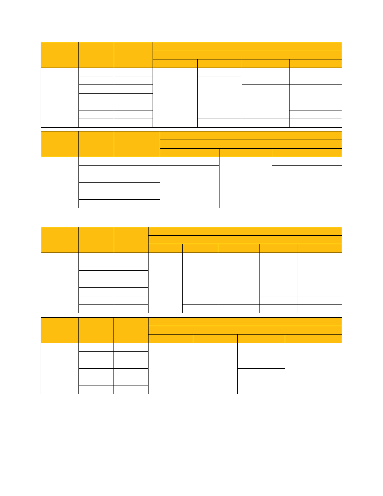
U1251A AC SPECIFICATIONS
FUNCTION RANGE RESOLUTION
50.000 mV 0.001 mV
500.00 mV 0.01 mV
TRUE RMS AC
VOLTAGE
FUNCTION RANGE RESOLUTION
AC CURRENT
1000.0 mV 0.1 mV
50.000 V 0.001 V
500.00 V 0.01 V 1.6+40
1000.0 V 0.1 V 0.6+40 1.0+40 N/A
500.00 µA
[2]
5000.0 µA 0.1 µA
440.00 mA 0.01 mA
5.0000 A 0.0001 A
[3]
10.000 A
ACCURACY ± (% of reading + No. of Least Signifi cant Digit)
30 Hz ~ 45 Hz 45 Hz ~ 1 kHz 1 kHz ~ 10 kHz 10 kHz ~ 30 kHz
1.0+60
ACCURACY ± (% of reading + No. of Least Signifi cant Digit)
30 Hz ~ 45 Hz 45 Hz ~ 2 kHz 2 kHz ~ 20 kHz
0.01 µA 1.5+50
1.5+40 3.0+60 50.000 mA 0.001 mA
0.001 A
2.0+40
FREQUENCY
0.6+40
0.6+25
1.0+40 1.6+60
1.0+25
1.6+405.0000 V 0.0001 V
[1]
FREQUENCY
3.0+80
0.8+20
[4]
3+60,
<3 A/5 kHz
U1252A/U1253A AC SPECIFICATIONS
FUNCTION RANGE RESOLUTION
50.000 mV 0.001 mV
500.00 mV 0.01 mV
TRUE RMS AC
VOLTAGE
FUNCTION RANGE RESOLUTION
AC CURRENT
1000.0 mV 0.1 mV
5.0000 V 0.0001 V
50.000 V 0.001 V
500.00 V 0.01 V 1.5+40 3.5+120
1000.0 V 0.1 V 0.4+40 0.4+40 1.5+40
500.00 µA
[2]
0.01 µA
5000.0 µA 0.1 µA
50.000 mA 0.001 mA
440.00 mA 0.01 mA 1.5+20
5.0000 A 0.0001 A
[3]
10.000 A
0.001 A
ACCURACY ± (% of reading + No. of Least Signifi cant Digit)
FREQUENCY
20 Hz ~ 45 Hz 45 Hz ~ 1 kHz 1 kHz ~ 10 kHz 10 kHz ~ 20 kHz 20 kHz~100 kHz
0.4+40 0.7+40
0.75+40 3.5+120
1.5+60
0.4+25 0.4+25
[1]
[1]
N/A
ACCURACY ± (% of reading + No. of Least Signifi cant Digit)
FREQUENCY
20 Hz ~ 45 Hz 45 Hz ~ 1 kHz 1 kHz ~ 20 kHz 20 kHz~100 kHz
1.0+20
0.75+20
5.0+80
[5]
0.7+20
1.5+20
[4]
3+60,
<3 A/5 kHz
N/A
[5]
[1] The input signal is lower than 20,000,000 V-Hz (the product of voltage and frequency).
[2] Input current >35 µArms.
[3] Current can be measured from 2.5 A up to 10 A continuously. An additional 0.5% needs to be added to the specifi ed accuracy if the signal measured is in the range
of 10 A ~ 20 A for 30 seconds maximum. After measuring a current of >10 A, leave the meter to cool down for twice the measuring time used before application of
low current measurement.
[4] Input current < 3 Arms.
[5] The additional error to be added as frequency >20 kHz and signal input<10% of range: 3 counts of LSD per kHz.
5

U1252A/U1253A AC+DC SPECIFICATIONS
FUNCTION RANGE RESOLUTION
50.000 mV 0.001 mV 1.5+80 0.4+60 0.7+60 0.8+60 3.5+220
500.00 mV 0.01 mV
TRUE RMS AC
VOLTAGE
FUNCTION RANGE RESOLUTION
AC CURRENT
1000.0 mV 0.1 mV
5.0000 V 0.0001 V
50.000 V 0.001 V
500.00 V 0.01 V 1.5+45 3.5+125
1000.00 V 0.1 V 0.4+45 0.4+45 1.5+45
500.00 µA
[3]
0.01 µA
5000.0 µA 0.1 µA
50.000 mA 0.001 mA
440.00 mA 0.01 mA
5.0000 A 0.0001 A
[4]
10.000 A
0.001 A 0.9+25
ACCURACY ± (% of reading + No. of Least Signifi cant Digit)
FREQUENCY
30 Hz ~ 45 Hz 45 Hz ~ 1 kHz 1 kHz ~ 10 kHz 10 kHz ~ 20 kHz 20 kHz~100 kHz
0.8+45 3.5+125
[2]
N/A
[2]
1.5+65
0.4+30 0.4+30
ACCURACY ± (% of reading + No. of Least Signifi cant Digit)
FREQUENCY
30 Hz ~ 45 Hz 45 Hz ~ 1 kHz 1 kHz ~ 20 kHz
1.1+25 0.8+25 0.8+25
1.2+25 0.9+25 0.9+25
1.8+30
[5]
0.9+30
3.3+70,
<3 A/5 kHz
[1]
CAPACITANCE SPECIFICATIONS
RANGE RESOLUTION ACCURACY
10.000 nF 0.001 nF 1% + 8
100.00 nF 0.01 nF
1000.0 nF 0.1 nF
10.000 µF 0.001 µF
100.00 µF 0.01 µF
1% + 5
1000.0 µF 0.1 µF 1 time/sec.
10.000 mF 0.001 mF 0.1 times/sec.
100.00 mF 0.01 mF 3% + 10 0.01 times/sec
FREQUENCY SPECIFICATIONS
[2]
RANGE RESOLUTION ACCURACY MIN. INPUT
U1251A/2A U1253A
99.999 Hz 0.001 Hz 0.02%+3
999.99 Hz 0.01 Hz
9.9999 kHz 0.0001 kHz
99.999 kHz 0.001 kHz
0.02%+3, <600 kHz 0.02%+3, <600 kHz
999.99 kHz 0.01 kHz
[1] The additional error to be added as frequency >20 kHz and signal input <10% of range: 3 counts of LSD per kHz.
[2] The input signal is lower than 20,000,000 V-Hz (the product of voltage and frequency).
[3] Input current >35 µArms.
[4] Current can be measured from 2.5 A up to 10 A continuously. An additional 0.5% needs to be added to the specifi ed accuracy if the signal measured is in the range
of 10 A ~ 20 A for 30 seconds maximum. After measuring a current of >10 A, leave the meter to cool down for twice the measuring time used before application of
low current measurement.
[5] Input current < 3 Arms.
[6] For non-square wave signals, add 5 counts.
MEASURING RATE AT
FULL SCALE
4 times/sec.
[6]
0.02%+3
MAX. DISPLAY
11000 counts
FREQUENCY
[6]
1 Hz
6

U1251A FREQUENCY SENSITIVITY DURING VOLTAGE MEASUREMENT
FREQUENCY SENSITIVITY AND TRIGGER LEVEL
INPUT RANGE MINIMUM SENSITIVITY
(Maximum input for specifi ed
accuracy = 10 x Range or 1000 V)
50.000 mV 10 mV 15 mV 10 mV 15 mV
500.00 mV 25 mV 35 mV 60 mV 70 mV
1000.0 mV 40 mV 50 mV 100 mV 150 mV
5.0000 V 0.25 V 0.5 V 0.5 V / 1.25 V (< 100 Hz) 0.6 V
50.000 V 2.5 V 5 V 5 V 6 V
500.00 V 25 V N/A 50 V N/A
1000.0 V 50 V N/A 300 V N/A
20 Hz - 100 kHz >100 kHz ~ 200 kHz < 100 kHz >100 kHz ~ 200 kHz
(R.M.S. Sine Wave)
U1252A/U1253A FREQUENCY SENSITIVITY DURING VOLTAGE MEASUREMENT
FREQUENCY SENSITIVITY AND TRIGGER LEVEL
INPUT RANGE MINIMUM SENSITIVITY
(Maximum input for specifi ed
accuracy = 10 x Range or 1000 V)
50.000 mV 10 mV 25 mV 10 mV 25 mV
500.00 mV 70 mV 150 mV 70 mV 150 mV
1000.0 mV 120 mV 300 mV 120 mV 300 mV
5.0000 V 0.3 V 1.2 V 0.6 V 1.5 V
50.000 V 3 V 5 V 6 V 15 V
500.00 V 30 V < 100 kHz N/A 60 V N/A
1000.0 V 50 V < 100 kHz N/A 120 V N/A
20 Hz ~ 200 kHz >200 kHz ~ 500 kHz < 100 kHz >100 kHz ~ 500 kHz
(R.M.S. Sine Wave)
TRIGGER LEVEL FOR DC COUPLING
TRIGGER LEVEL FOR DC COUPLING
FREQUENCY SENSITIVITY DURING CURRENT MEASUREMENT
INPUT RANGE MINIMUM SENSITIVITY (R.M.S. Sine Wave)
500.00 µA 100 µA
5000.0 µA 250 µA
50.000 mA 10 mA
440.00 mA 25 mA
5.0000 A 1 A
10.000 A 2.5 A
20 Hz ~ 20 kHz
PEAK HOLD
SIGNAL WIDTH ACCURACY FOR DC mV/VOLTAGE/CURRENT
Single event > 1 ms 2% + 400 for all ranges
Repetitive > 250 µs 2% + 1000 for all ranges
DUTY CYCLE AND PULSE WIDTH
FUNCTION MODE RANGE ACCURACY AT FULL SCALE
DUTY CYCLE DC Coupling 0.01% ~ 99.99% 0.3% per kHz + 0.3%
PULSE WIDTH 500 ms 0.01 ms 0.2% + 3
[1]
2000 ms 0.1 ms 0.2% + 3
[1] The positive or negative pulse width must be greater than 10 µs, and the duty cycle range should be considered. The pulse width range is determined by the frequency
of the signal.
7

U1252A/U1253A FREQUENCY COUNTER SPECIFICATIONS
DIVISION RANGE RESOLUTION ACCURACY ± (% of reading + No. of
Least Signifi cant Digit)
U1252A U1253A
(secondary display “-1-“)
1
99.999 Hz 0.001 Hz 0.02% + 3
999.99 Hz 0.01 Hz
[1]
9.9999 kHz 0.0001 kHz
99.999 kHz 0.001 kHz
0.002% + 5, < 2
MHz
999.99 kHz 0.01 kHz
9.9999 MHz 0.0001 MHz
(secondary display “-100-“)
100
9.9999 MHz 0.0001 MHz
99.999 MHz 0.001 MHz
0.002% + 5, < 20
MHz
0.02% + 3
[1]
0.002% + 5, <
985 kHz
0.002% + 5, < 20
MHz
SENSITIVITY MIN. INPUT
100 mV R.M.S.
200 mV R.M.S.
400 mV R.M.S.
600 mV R.M.S.
U1252A/U1253A SQUARE WAVE OUTPUT
[2]
OUTPUT
FREQUENCY 0.5, 1, 2, 5, 6
40, 50, 60, 75, 80, 100, 120, 150,
200, 240, 300, 400, 480, 600, 800,
1200, 1600, 2400, 48000 Hz
DUTY CYCLE
PULSE WIDTH
[3]
[4]
AMPLITUDE Fixed 0 ~ +2.8 V 0.1 V 0.2 V
RANGE RESOLUTION ACCURACY
[6]
, 10, 15, 20, 25, 30,
0.01 Hz 0.005% + 2
0.39% ~ 99.60% 0.390625% 0.4% of full scale
1/Frequency Range/256 0.2 ms + Range/256
FREQUENCY
0.5 Hz
1 MHz
[4]
MEASURING RATE
FUNCTION TIMES/SECOND
ACV 7
MANUAL AND INTERVAL DATA LOGGING
LOGGING
TYPE
MAXIMUM DATA POINTS
U1251A U1252A U1253A
[5]
ACV + dB 7
DCV 7
AC + DC V 2
W /nS
14
MANUAL 100 100 100
INTERVAL 200 200 1000
DECIBEL (dB) CALCULATION
Diode 14
Capacitance 4 (< 100 µF)
DCI 7
ACI 7
AC + DC I 2
Temperature 6
Frequency 1 (>10 Hz)
Duty cycle/Pulse width 0.5 (>10 Hz)
[1] All frequency counters are susceptible to errors. Shielding inputs from external noise pickup is critical to minimize measurement errors. For non-square wave signals,
add 5 counts.
[2] Output impedance: 3.5 kW maximum.
[3] The positive or negative pulse width must be greater than 50 µs for adjustment of the duty cycle or pulse width under different frequencies. Otherwise, the accuracy
and range will be different from the specifi cations defi ned.
[4] For signal frequencies greater than 1 kHz, an addition of 0.1% per kHz is added to the accuracy.
[5] For data logging to PC, maximum number of data points is dependent on available hard disk space.
[6] For the U1253A model.
dB BASE REFERENCE DEFAULT REFERENCE
1 mW (dBm) 1-9999 W 50 W
1 V (dBV) 1 V 1 V
8

GENERAL SPECIFICATIONS
DISPLAY
Both primary and secondary displays are 5-digit on the LCD display.
Both the primary and secondary displays offer a maximum resolution
of 50,000 counts. Automatic polarity indication.
POWER CONSUMPTION
105 mVA / 420 mVA (with backlight) maximum (U1251A)
165 mVA / 480 mVA (with backlight) maximum (U1252A)
420 mVA maximum (U1253A)
BATTERY TYPE
9 V Alkaline battery (ANSI/NEDA 1604A or IEC 6LR61)
9 V Carbon-zinc battery (ANSI/NEDA 1604D or IEC6F22)
7.2 V Ni-MH Rechargeable battery
BATTERY LIFE
U1251A: 72 hours typical
U1252A: 36 hours typical
U1253A: 8 hours typical
OPERATING ENVIRONMENT
• Full accuracy at –20 oC to 55 oC ; and to 80% RH for temperatures
up to 35 °C, decreasing linearly to 50% RH at 55 °C
• 0 to 2000 m altitude per IEC 61010-1 2nd Edition CAT III, 1000 V;
2000 to 3000 m altitude per IEC 61010-1 2nd Edition CAT III, 600 V
STORAGE COMPLIANCE
–40 oC to 70 oC
SAFETY COMPLIANCE
Certifi ed by CSA for IEC/EN/CSA/UL 61010-1 2nd Edition and
CAN/CSA 22.2 61010-1 2nd Edition
MEASUREMENT CATEGORY
CAT III 1000 V Overvoltage Protection up to 2000 m, Pollution degree 2
EMC COMPLIANCE
Certifi ed to IEC/EN 61326: 2002, CISPR 11, and equivalents for
Group 1, Class A
COMMON MODE REJECTION RATIO (CMRR)
U1251A/2A: >90 dB at DC, 50/60 Hz ± 0.1% (1 kW unbalanced)
U1253A: >100 dB at DC, 50/60 Hz ± 0.1% (1 kW unbalanced)
NORMAL MODE REJECTION RATIO (NMRR)
U1251A/2A: >60 dB at DC, 50/60 Hz ± 0.1%
U1253A: >90 dB at DC, 50/60 Hz ± 0.1%
CREST FACTOR
< 3.0
TEMPERATURE COEFFICIENT
0.15 * (specifi ed accuracy)/
SHOCK and VIBRATION
Tested to IEC/EN 60068-2
DIMENSIONS (HxWxD)
203.5 mm x 94.4 mm x 59.0 mm
WEIGHT
U1251A: 504±5 g with battery
U1252A/3A: 527±5 g with battery (U1252A)
CHARGING TIME (only U1252A/3A)
< 220 minutes approx. at the environment of 10 oC to 30 oC
WARRANTY
3 years
o
C (from 20 oC to 18 oC or 28 oC to 55 oC)
9

STANDARD SHIPPED ITEMS
DESCRIPTION APPLICABLE MODELS
U1251A U1252A U1253A
Alligator clips • • •
SMT grabbers • • –
Fine-tip test probes • • –
Test probe leads • • •
Mini grabber • • –
Alkaline 9 V battery • – –
Rechargeable Ni-MH battery with
power adapter
GUI data logging software (in
Product Reference CD)
Soft carrying case • • –
Certifi cate of Calibration • • •
Test Report • • •
Quick Start Guide • • •
User’s and Service Guide (in Product Reference CD)
–••
•••
•••
U1253A OPTION
Option 001 Bundled SMT grabbers, fi ne-tip test probes and soft carrying case
OPTIONAL ACCESSORIES
MEASURING ACCESSORIES (NON-TEMPERATURE)
U1160A Standard test lead kit
U1163A SMT grabbers
U1161A Extended test lead kit
U1164A Fine-tip test probes
U1162A Alligator clips
U1165A Test probe leads
U1583A AC current clamp
34136A High voltage probe
10

MEASURING ACCESSORIES (TEMPERATURE)
U1180A Thermocouple
adapter+lead kit, J and K types
U1183A Air temperature probe
U1186A K-type thermocouple and
adapter
CABLE
U1181A Immersion temperature probe
U1184A Temperature probe adapter
CARRYING CASE
U1182A Industrial surface temperature probe
U1185A J-type thermocouple and
adapter
U1173A IR-to-USB cable
HANGING KIT
U1171A Magnetic hanging kit
U1172A Transit case (aluminium-clad)
AC ADAPTOR
U1170A AC adaptor
11
U1174A Soft carrying case

Agilent Email Updates
www.agilent.com/fi nd/emailupdates
Get the latest information on the
products and applications you select.
Agilent Direct
www.agilent.com/find/agilentdirect
Quickly choose and use your test
equipment solutions with confi dence.
Remove all doubt
Our repair and calibration services
will get your equipment back to you,
performing like new, when promised. You will get full value out of
your Agilent equipment throughout its lifetime. Your equipment
will be serviced by Agilent-trained
technicians using the latest factory
calibration procedures, automated
repair diagnostics and genuine parts.
You will always have the utmost
confi dence in your measurements.
Agilent offers a wide range of additional expert test and measurement services for your equipment,
including initial start-up assistance
onsite education and training, as
well as design, system integration,
and project management.
For more information on repair and
calibration services, go to
www.agilent.com/fi nd/removealldoubt
www.agilent.com
www.agilent.com/fi nd/handhelddmm
For more information on Agilent Technologies’
products, applications or services, please
contact your local Agilent office. The complete list is available at:
www.agilent.com/fi nd/contactus
Phone or Fax
Americas
Canada
Latin America
United States
Asia Pacifi c
Australia
China
Hong Kong
India
Japan
Korea
Malaysia
Singapore
Taiwan
Thailand
(877) 894-4414
305 269 7500
(800) 829-4444
1 800 629 485
800 810 0189
800 938 693
1 800 112 929
0120 (421) 345
080 769 0800
1 800 888 848
1 800 375 8100
0800 047 866
1 800 226 008
Europe & Middle East
Austria
Belgium
Denmark
Finland
France
Germany
Ireland
Israel
Italy
Netherlands
Spain
Sweden
Switzerland
United Kingdom
01 36027 71571
32 (0) 2 404 93 40
45 70 13 15 15
358 (0) 10 855 2100
0825 010 700*
/minute
*0.125
07031 464 6333**
/minute
**0.14
1890 924 204
972-3-9288-504/544
39 02 92 60 8484
31 (0) 20 547 2111
34 (91) 631 3300
0200-88 22 55
0800 80 53 53
44 (0) 118 9276201
Other European Countries:
www.agilent.com/fi nd/contactus
Revised: July 17, 2008
Product specifi cations and descriptions
in this document subject to change
without notice.
© Agilent Technologies, Inc. 2008
Printed in USA, September 22, 2008
5989-5509EN
 Loading...