

Page 1

Agilent U1190A Series
Handheld Clamp Meters
User’s Guide
Agilent Technologies
Page 2

Notices
CAUTION
WARNING
© Agilent Technologies, Inc., 2011
No p art o f this manu al may be re produce d in
any form or by any means (including electronic storage and retrieval or translation
into a foreign language) without prior agreement and written consent from Agilent
Technologies, Inc. as governed by United
States and international copyright laws.
Manual Part Number
U1191-90003
Edition
First Edition, September 2011
Agilent Technologies, Inc.
5301, Stevens Creek Blvd.
Santa Clara, CA 95051 USA
Warranty
The material contained in this document is
provided “as is,” and is subject to change,
without notice, in future editions. Further,
to the maximum extent permitted by the
applicable law, Agilent disclaims all warranties, either express or implied, with
regard to this manual and any information
contained herein, including but not limited
to the implied warranties of merchantability and fitness for a particular purpose.
Agilent shall not be liable for errors or for
incidental or consequential damages in
connection with the furnishing, use, or
performance of this document or of any
information contained herein. Should Agilent and the user have a separate written
agreement with warranty terms covering
the material in this document that conflict
with these terms, the warranty terms in
the separate agreement shall control.
Technology Licenses
The hardware and or software described in
this document are furnished under a license
and may be used or copied only in accordance with the terms of such license.
Restricted Rights Legend
U.S. Government Restricted Rights. Software and technical data rights granted to
the federal government include only those
rights customarily provided to end user customers. Agilent provides this customary
commercial license in Software and technical data pursuant to FAR 12.211 (Technical
Data) and 12.212 (Computer Software) and,
for the Department of Defense, DFARS
252.227-7015 (Technical Data - Commercial
Items) and DFARS 227.7202-3 (Rights in
Commercial Computer Software or Computer Software Documentation).
Safety Notices
A CAUTION notice denotes a hazard. It calls attention to an operating procedure, practice, or the likes
of that, if not correctly performed
or adhered to, could result in damage to the product or loss of important data. Do not proceed beyond a
CAUTION notice until the indicated
conditions are fully understood and
met.
A WARNING notice denotes a
hazard. It calls attention to an
operating procedure, practice, or
the likes of that, if not correctly
performed or adhered to, could
result in personal injury or death.
Do not proceed beyond a WARNING notice until the indicated
conditions are fully understood
and met.
II U1190A Series User’s Guide
Page 3
Safety Symbols
400 A
MAX
600 A
MAX
CAT III
600 V
CAT IV
300 V
The following symbols on the instrument and in the documentation
indicate precautions which must be taken to maintain safe operation of
the instrument.
DC (Direct current or voltage)
AC (Alternating current or voltage)
Both direct and alternating current
Earth (ground) terminal
Equipment protected throughout by
double insulation or reinforced
insulation
Caution, risk of electric shock Category IV 300 V overvoltage protection
Caution, risk of danger (refer to this manual
for specific Warning or Caution information)
Application around and removal from
HAZARDOUS LIVE conductors is permitted
U1191A/U1192A: Maximum allowable
current measurement is 400 A
U1193A/U1194A: Maximum allowable
current measurement is 600 A
Category III 600 V overvoltage protection
U1190A Series User’s Guide III
Page 4

Safety Considerations
CAUTION
WARNING
Read the information below before using this instrument.
The following general safety precautions must be observed during all
phases of operation, service, and repair of this instrument. Failure to
comply with these precautions or with specific warnings elsewhere in this
manual violates safety standards for design, manufacture, and intended
use of the instrument. Agilent Technologies assumes no liability for the
customer’s failure to comply with these requirements.
• Disconnect circuit power and discharge all high-voltage capacitors
before testing resistance, continuity, diodes, or capacitance.
• Use the proper terminals, function, and range for your
measurements.
• This device is for use at altitudes of up to 2,000 m.
• Never measure voltage when current measurement is selected.
• Always use the specified battery type. The power for the meter is
supplied with two standard AAA 1.5 V batteries. Observe the
correct polarity markings before you insert the batteries to ensure
proper insertion of the batteries in the meter.
IV U1190A Series User’s Guide
• Do not use the meter if it is damaged. Before you use the meter,
inspect the case. Look for cracks or missing plastic. Pay
particular attention to the insulation surrounding the connectors.
• Inspect the test leads for damaged insulation or exposed metal.
Check the test leads for continuity. Replace damaged test leads
before you use the meter.
• Do not operate the meter around explosive gas, vapor, or wet
environments.
• Do not apply more than the rated voltage and current (as marked
on the meter) between the terminals or between the terminal and
the earth ground.
Page 5

WARNING
• Never use the meter in wet conditions or when there is water on
the surface. If the meter is wet, ensure that the meter is dried only
by trained personnel.
• Before use, verify the meter's operation by measuring a known
voltage. Use caution when working above 60 V DC, 30 V AC RMS,
or 42.4 V peak. Such voltages pose a shock hazard.
• When measuring current, turn off the circuit power before
connecting the meter in the circuit. Remember to place the meter
in series with the circuit.
• When measuring temperature, keep the thermocouple probe as
close to the meter as possible, and avoid contact with surfaces
above 60 V DC, 30 V AC RMS, or 42.4 V peak. Such voltages pose a
shock hazard.
• When servicing the meter, use only the specified replacement
parts.
• When using the probes, keep your fingers behind the finger
guards on the probes.
• Connect the common test lead before you connect the live test
lead. When you disconnect the leads, disconnect the live test lead
first.
U1190A Series User’s Guide V
• Remove the test leads from the meter before you open the battery
cover. Do not operate the meter with the battery cover or portions
of the cover removed or loosened.
• To avoid false readings, which may lead to possible electric shock
or personal injury, replace the battery as soon as the low battery
indicator appears and flashes.
• Use the meter only as specified in this guide. Otherwise, the
protection provided by the meter may be impaired.
• Individual protective equipment must be used if hazardous live
parts in the installation are accessible where measurement is to
be carried out.
• The tactile indicator or barrier, indicates the limit of safe access
of the handheld part.
Page 6

Environmental Conditions
NOTE
This instrument is designed for indoor use and in an area with low
condensation. The table below shows the general environmental
requirements for this instrument.
Environmental conditions Requirements
Operating temperature –10 °C to 50 °C
Up to 80% RH (relative humidity) for temperature
Operating humidity
up to 30 °C, decreasing linearly to 50% RH at
50 °C
Storage temperature
Altitude Up to 2000 meters
Pollution degree Pollution degree 2
The U1190A Series Handheld Clamp Meter complies with the following safety and
EMC requirements:
• IEC 61010-1:2001/EN 61010-1:2001
• IEC 61010-2-032:2002/EN 61010-2-032:2002
• CAN/CSA-C22.2 No. 61010-1-04
• CAN/CSA-C22.2 No. 61010-2-032-04
• ANSI/UL Std. No. 61010-1:2004
• IEC61326-1:2005/EN61326-1:2006
• Canada: ICES/NMB-001: Issue 4, June 2006
• Australia/New Zealand: AS/NZS CISPR 11:2004
–40 °C to 60 °C, 40% to 80% RH (without
batteries)
VI U1190A Series User’s Guide
Page 7
Regulatory Markings
The CE mark is a registered trademark
of the European Community. This CE
mark shows that the product complies
with all the relevant European Legal
Directives.
The C-tick mark is a registered
trademark of the Spectrum
Management Agency of Australia. This
signifies compliance with
the Australia EMC Framework
regulations under the terms of the
Radio Communication Act of 1992.
ICES/NMB-001 indicates that this ISM
device complies with the Canadian
ICES-001.
Cet appareil ISM est confomre a la
norme NMB-001 du Canada.
The CSA mark is a registered
trademark of the Canadian Standards
Association.
This instrument complies with the
WEEE Directive (2002/96/EC) marking
requirement. This affixed product label
indicates that you must not discard
this electrical or electronic product in
domestic household waste.
This symbol indicates the time period
during which no hazardous or toxic
substance elements are expected to
leak or deteriorate during normal use.
Forty years is the expected useful life
of the product.
U1190A Series User’s Guide VII
Page 8
Waste Electrical and Electronic Equipment (WEEE) Directive 2002/96/EC
This instrument complies with the WEEE Directive (2002/96/EC) marking
requirement. This affixed product label indicates that you must not discard
this electrical or electronic product in domestic household waste.
Product Category:
With reference to the equipment types in the WEEE directive Annex 1, this
instrument is classified as a “Monitoring and Control Instrument” product.
The affixed product label is as shown below.
Do not dispose in domestic household waste.
To return this unwanted instrument, contact your nearest Agilent Service
Center, or visit
www.agilent.com/environment/product
for more information.
VIII U1190A Series User’s Guide
Page 9

Declaration of Conformity (DoC)
NOTE
The Declaration of Conformity (DoC) for this instrument is available on the
Agilent website. You can search the DoC by its product model or
description at the web address below.
http://regulations.corporate.agilent.com/DoC/search.htm
If you are unable to search for the respective DoC, please contact your
local Agilent representative.
U1190A Series User’s Guide IX
Page 10

THIS PAGE HAS BEEN INTENTIONALLY LEFT BLANK.
X U1190A Series User’s Guide
Page 11

Table of Contents
1 Introduction
About This Manual 2
Documentation map 2
Safety notes 2
Preparing Your Clamp Meter 3
Checking the shipment 3
Installing the batteries 3
Turning on your clamp meter 6
Automatic Power-Off (APO) 7
Enabling the backlight 7
Enabling the flashlight 8
Alerts and warnings during measurement 9
Power-on options 10
Your Clamp Meter in Brief 11
Dimensions 11
Overview 13
Rotary switch 15
Keypad 17
Display screen 18
Input terminals 21
Cleaning Your Clamp Meter 23
2 Making Measurements
Measuring AC or DC Current 26
Measuring AC Voltage 30
Measuring DC Voltage 32
Measuring Resistance 34
Testing for Continuity 36
U1190A Series User’s Guide XI
Page 12

Testing Diodes 39
Measuring Capacitance 43
Measuring Temperature 45
Measuring AC or DC Current (up to µA) 48
Measuring Frequency 50
3 Clamp Meter Features
Detecting AC Voltage Presence (Vsense) 54
Making Relative Measurements (Null) 57
Capturing Maximum and Minimum Values (Max.Min) 58
Freezing the Display (Hold) 60
4 Characteristics and Specifications
Product Characteristics 62
Specification Assumptions 64
Measurement Category 65
Measurement category definition 65
Electrical Specifications 66
DC specifications 66
AC specifications 68
Capacitance specifications 69
Temperature specifications 70
Frequency specifications 71
Frequency sensitivity specifications 71
Display update rate (approximate) 72
XII U1190A Series User’s Guide
Page 13

List of Figures
Figure 1-1 Installing the batteries 4
Figure 1-2 Powering on the clamp meter 6
Figure 1-3 Front panel 13
Figure 1-4 Rear panel 14
Figure 2-1 AC current display 27
Figure 2-2 Measuring AC current 27
Figure 2-3 Wire separator and hook design 28
Figure 2-4 AC voltage display 30
Figure 2-5 Measuring AC voltage 31
Figure 2-6 DC voltage display 32
Figure 2-7 Measuring DC voltage 33
Figure 2-8 Resistance display 34
Figure 2-9 Measuring resistance 35
Figure 2-10 Open continuity display 36
Figure 2-11 Closed continuity display 36
Figure 2-12 Testing for continuity 38
Figure 2-13 Diode display 39
Figure 2-14 Open diode display 40
Figure 2-15 Testing forward-bias diode 41
Figure 2-16 Testing reverse-bias diode 42
Figure 2-17 Capacitance display 43
Figure 2-18 Measuring capacitance 44
Figure 2-19 Temperature display 45
Figure 2-20 Measuring the surface temperature 47
Figure 2-21 DC current display 48
Figure 2-22 Measuring AC/DC current (up to µA) 49
Figure 2-23 Frequency display 51
Figure 2-24 Measuring frequency 51
Figure 3-1 Vsense (high sensitivity) display 55
Figure 3-2 Vsense (low sensitivity) display 55
Figure 3-3 Detecting voltage presence 56
Figure 3-4 Null display 57
Figure 3-5 Max.Min display 58
Figure 3-6 Hold display
60
U1190A Series User’s Guide XIII
Page 14

THIS PAGE HAS BEEN INTENTIONALLY LEFT BLANK.
XIV U1190A Series User’s Guide
Page 15

List of Tables
Tab le 1- 1 Battery level indicator 5
Tab le 1- 2 Power-on options 10
Tab le 1- 3 Rotary switch functions 16
Tab le 1- 4 Keypad functions 17
Tab le 1- 5 General annunciators 18
Tab le 1- 6 Measurement units display 20
Tab le 1- 7 Terminal connections for different measuring
functions 21
Tab le 4- 1 DC specifications 66
Tab le 4- 2 AC voltage specifications 68
Tab le 4- 3 AC current specifications 68
Tab le 4- 4 Capacitance specifications 69
Tab le 4- 5 Temperature specifications 70
Tab le 4- 6 Frequency specifications 71
Tab le 4- 7 Frequency sensitivity and trigger-level specifications for
voltage measurements 71
Tab le 4- 8 Frequency sensitivity and trigger level specifications for
current measurements 72
Tab le 4- 9 Display update rate (approximate) 72
U1190A Series User’s Guide XV
Page 16

THIS PAGE HAS BEEN INTENTIONALLY LEFT BLANK.
XVI U1190A Series User’s Guide
Page 17

U1190A Series Handheld Clamp Meter
User’s Guide
1 Introduction
About This Manual 2
Documentation map 2
Safety notes 2
Preparing Your Clamp Meter 3
Checking the shipment 3
Installing the batteries 3
Turning on your clamp meter 6
Automatic Power-Off (APO) 7
Enabling the backlight 7
Enabling the flashlight 8
Alerts and warnings during measurement 9
Power-on options 10
Your Clamp Meter in Brief 11
Dimensions 11
Overview 13
Rotary switch 15
Keypad 17
Display screen 18
Input terminals 21
Cleaning Your Clamp Meter 23
This chapter teaches you how to set up your clamp meter
for the first time. An introduction to all the features of the
clamp meter is also given.
Agilent Technologies
1
Page 18

1 Introduction
About This Manual
About This Manual
The descriptions and instructions in this manual apply to
the Agilent U1191A, U1192A, U1193A, and U1194A handheld
clamp meters (hereafter referred to as the clamp meter).
The model U1194A appears in all illustrations.
Documentation map
The following manuals and software are available for your
clamp meter. For the very latest version, please visit our
website at: http://www.agilent.com/find/hhTechLib.
Check the manual revision on the first page of each manual.
• User’s Guide. This manual.
•Quick Start Guide. Printed copy for outdoor use,
included with shipment.
• Service Guide. Free download at the Agilent website.
Safety notes
Safety notes are used throughout this manual (see the
“Safety Notices” section for format examples). Familiarize
yourself with each of the notes and its meaning before
operating your clamp meter.
More pertinent safety notes for using this product are
located under the “Safety Considerations” section.
Do not proceed beyond a safety notice until the indicated
conditions are fully understood and met.
2 U1190A Series User’s Guide
Page 19

Preparing Your Clamp Meter
CAUTION
Checking the shipment
When you receive your clamp meter, check the shipment
according to the following procedure.
1 Inspect the shipping container for damage. Signs of
damage may include a dented or torn shipping container
or cushioning material that indicates signs of unusual
stress or compacting. Save the packaging material in case
the clamp meter needs to be returned.
2 Carefully remove the contents from the shipping
container, and verify that the standard accessories and
your ordered options are included in the shipment
according to the standard shipped items list found in the
printed copy of the U1190A Series Quick Start Guide.
3 For any question or problems, refer to the Agilent contact
numbers on the back of this manual.
Introduction 1
Preparing Your Clamp Meter
U1190A Series User’s Guide 3
Installing the batteries
Your clamp meter is powered by two 1.5 V AAA alkaline
batteries (included with the shipment). When you receive
your clamp meter, the AAA alkaline batteries are not
installed.
Use the following procedure to install the batteries.
Before you proceed with the batteries installation, remove all cable
connections to the terminals and ensure that the rotary switch is at the
OFF position. Use only the battery type specified in the “Product
Characteristics” on page 62.
Page 20
1 Introduction
Preparing Your Clamp Meter
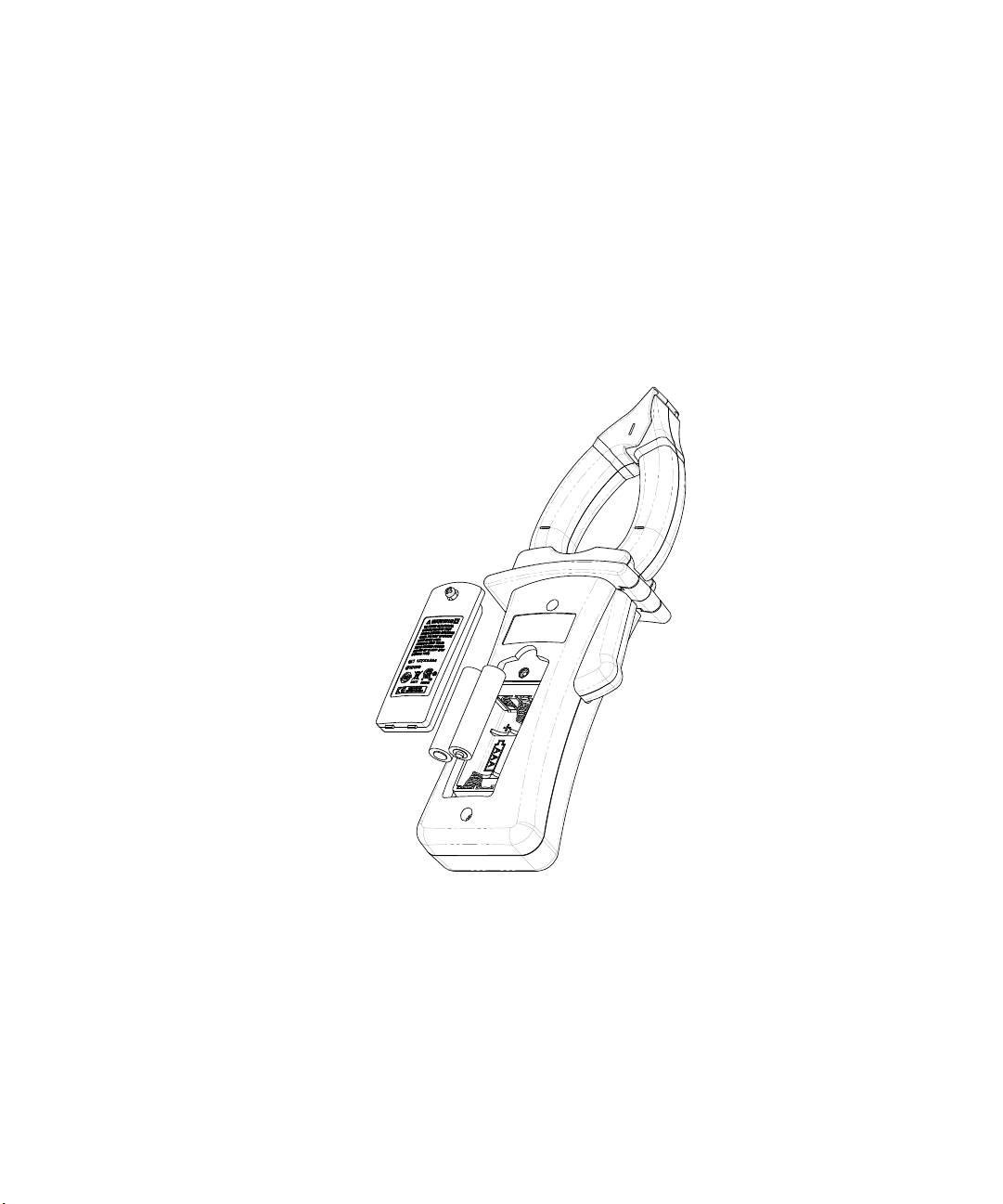
1 Open the battery cover. Loosen the screw with a suitable
Phillips screwdriver and remove the battery cover as
shown in Figure 1-1.
2 Insert the batteries. Observe the proper battery polarity.
The terminal ends of each battery are indicated inside the
battery compartment.
3 Close the battery cover. Place the battery cover back in
its original position and tighten the screw.
Figure 1-1 Installing the batteries
The battery level indicator in the lower left- hand corner of
the display indicates the relative condition of the batteries.
Table 1- 1 describes the various battery levels the indicator
represents.
4 U1190A Series User’s Guide
Page 21
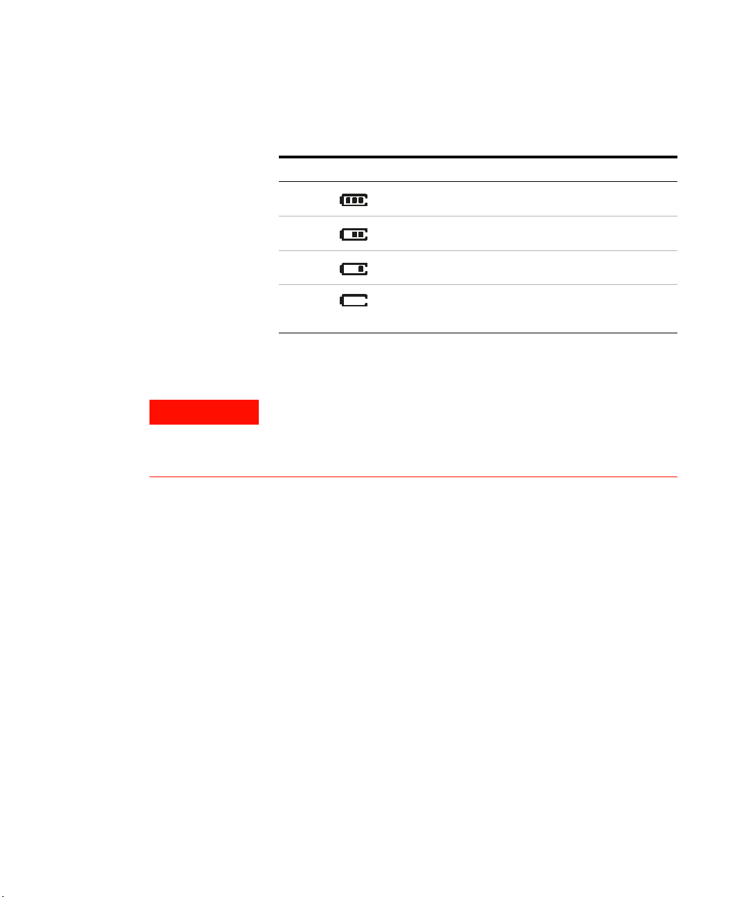
Tab l e 1 - 1 Battery level indicator
WARNING
Indication Battery capacity
Full capacity
2/3 capacity
1/3 capacity
Introduction 1
Preparing Your Clamp Meter
(Flashing periodically)
[1] Batteries change advised. Always use the specified battery type listed in the
“Product Characteristics” on page 62.
Almost empty
[1]
To avoid false readings, which could lead to possible electric shock
or personal injury, replace the batteries as soon as the low battery
indicator appears. Do not discharge the batteries by shorting the
batteries or reversing the polarity of the batteries.
U1190A Series User’s Guide 5
Page 22
1 Introduction
Preparing Your Clamp Meter
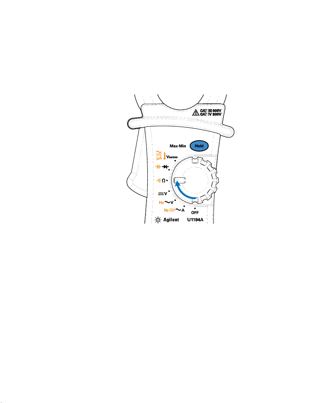
Turning on your clamp meter
To power ON your clamp meter, turn the rotary switch from
the OFF position to any other position.
Figure 1-2 Powering on the clamp meter
To power OFF your clamp meter, turn the rotary switch to
the OFF position.
6 U1190A Series User’s Guide
Page 23
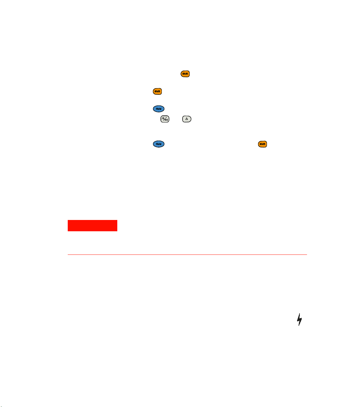
Automatic Power-Off (APO)
NOTE
Your clamp meter automatically turns off if the rotary
switch is not moved or a key is not pressed for 15 minutes
(default). The clamp meter will beep thrice before it powers
off. Pressing any key or turning the rotary switch to a new
position will turn the clamp meter back on after it is
powered off automatically.
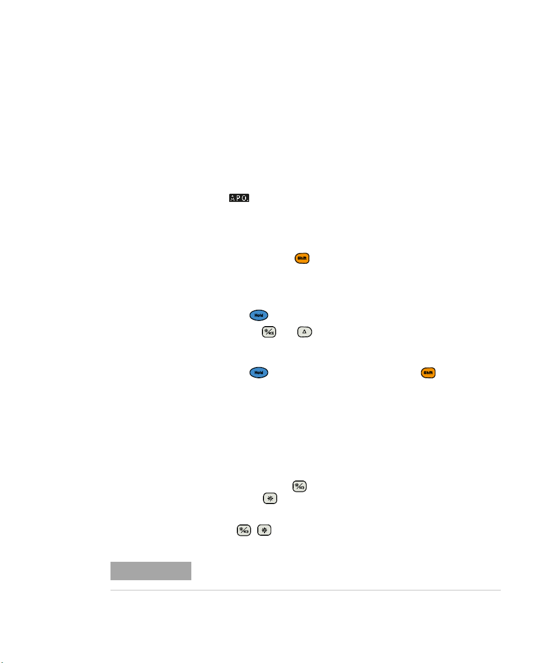
The symbol is shown on the bottom left of the display
when the automatic power-off function is enabled.
Follow the steps below to change the timer period or
completely disable the automatic power-off.
1 Press and hold while powering on the clamp meter to
enter the Setup menu.
2 The automatic power- off (A #) timer period is the first
Setup item shown.
3 Press to make changes to the A # value.
Press or to change the timer period (from
A 01 to A 99 minutes) or to completely disable the
automatic power-off function (AoFF).
4 Press to save the changes, or press to discard
the changes and proceed to the next Setup item.
5 Cycle the clamp meter’s power to exit the Setup menu.
Introduction 1
Preparing Your Clamp Meter
Enabling the backlight
If viewing the display becomes difficult in low- light
conditions, press (on the U1192A/U1193A/U1194A
models) or (on the U1191A model) to activate the LCD
backlight.
Press / again to deactivate the LCD backlight.
To conserve battery life, a user-adjustable timer controls how long the
backlight stays on. The default timer period is 15 seconds.
U1190A Series User’s Guide 7
Page 24
1 Introduction
WARNING
NOTE
Preparing Your Clamp Meter
Follow the steps below to change the timer period or
completely disable the backlight timer.
1 Press and hold while powering on the clamp meter to
enter the Setup menu.
2 Press again. The backlight (b #) timer period is the
second Setup item shown.
3 Press to make changes to the b # value.
Press or to change the timer period (from
b 01 to b 99 seconds) or to completely disable the
backlight timer function (boFF).
4 Press to save the changes, or press to discard
the changes and proceed to the next Setup item.
5 Cycle the clamp meter’s power to exit the Setup menu.
Enabling the flashlight
This feature is applicable for U1192A, U1193A, and U1194A
models only.
8 U1190A Series User’s Guide
If you are using the clamp meter in dark places, press and
hold for more than 1 second to activate the LED
flashlight for greater visibility on your test points. This is
not applicable to the U1191A model.
Press for more than 1 second to deactivate the LED
flashlight.
VISION ADVISORY CLAIM
It is advised that you do not look directly into the light source of the
LED flashlight. As with any source of bright light, prolonged
exposure can damage the eye.
To conserve battery life, a user-adjustable timer can be set to control how
long the flashlight stays on. This function is disabled by default.
Page 25
Preparing Your Clamp Meter
WARNING
Follow the steps below to change the timer period or
completely disable the flashlight timer.
1 Press and hold while powering on the clamp meter to
enter the Setup menu.
2 Press twice. The f lashlight (t #) timer period is the
third Setup item shown.
3 Press to make changes to the t # value.
Press or to change the timer period (from
t 01 to t 99 seconds) or to completely disable the
flashlight timer function (toFF).
4 Press to save the changes, or press to discard
the changes and proceed to the next Setup item.
5 Cycle the clamp meter’s power to exit the Setup menu.
Alerts and warnings during measurement
Voltage alert
Introduction 1
U1190A Series User’s Guide 9
For your own safety, please do not ignore the voltage alert. When the
clamp meter cautions you with a voltage alert, you are advised to
take note of the existence of high voltage and pay closer attention
when performing measurements.
Your clamp meter provides a voltage alert for voltage
measurements. The clamp meter starts beeping periodically
once the measured voltage exceeds the alert value
(regardless of polarity) set.
Hazardous voltage indication
The clamp meter will also display the hazardous voltage ( )
symbol as an early precaution when the measured voltage is
equal to or greater than 30 V in all voltage measurement
modes.
Page 26
1 Introduction
+
Preparing Your Clamp Meter
Power-on options
Some options can be selected only while you turn the clamp
meter on. These power- on options are listed in the table
below.
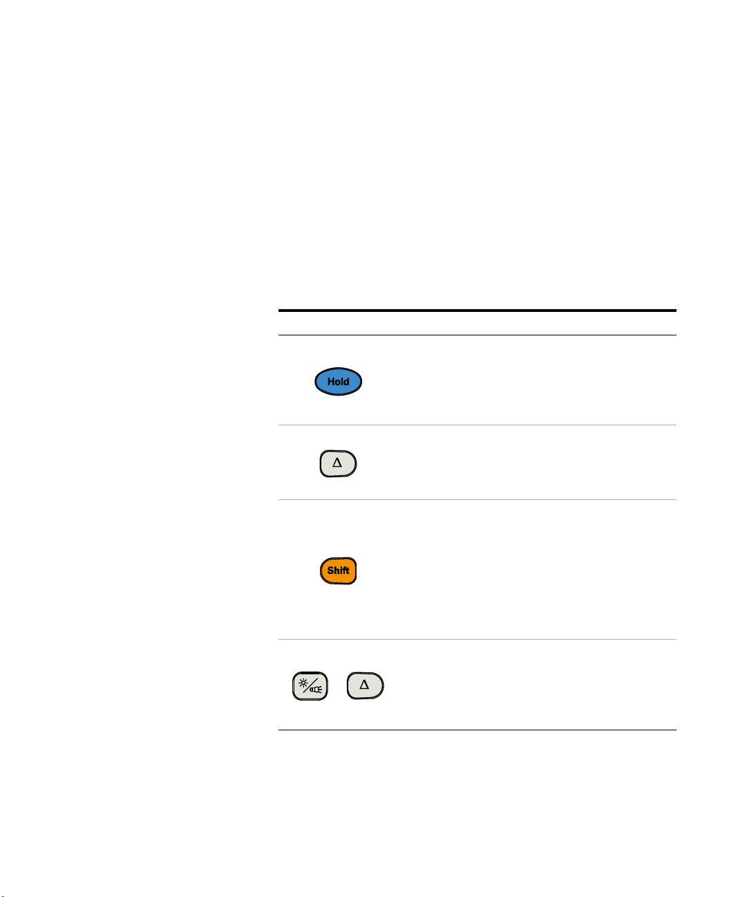
To select a power- on option, press and hold the specified
key in Table 1- 2 while turning the rotary switch from the
OFF position to any other position.
Tab l e 1 - 2 Power-on options
Key Description
Tests the LCD.
All annunciators are displayed in the LCD for 10
seconds. Cycle the clamp meter’s power to exit this
mode, or wait 10 seconds for the clamp meter to return
to normal operation.
Checks the firmware version.
The clamp meter’s firmware version will be shown on
the primary display. Cycle the clamp meter’s power to
exit this mode.
Enters the clamp meter’s Setup menu.
See the following topics for more information on each
respective Setup menu item.
• “Automatic Power-Off (APO)” on page 7
• “Enabling the backlight” on page 7
• “Enabling the flashlight” on page 8
• “Changing the continuity visual alert” on page 37
Cycle the clamp meter’s power to exit the Setup menu.
Enters the unit selection menu for temperature
measurements (U1194A only).
See “Changing the default temperature unit” on
page 46 for more information. Cycle the clamp meter’s
power to exit this menu.
10 U1190A Series User’s Guide
Page 27
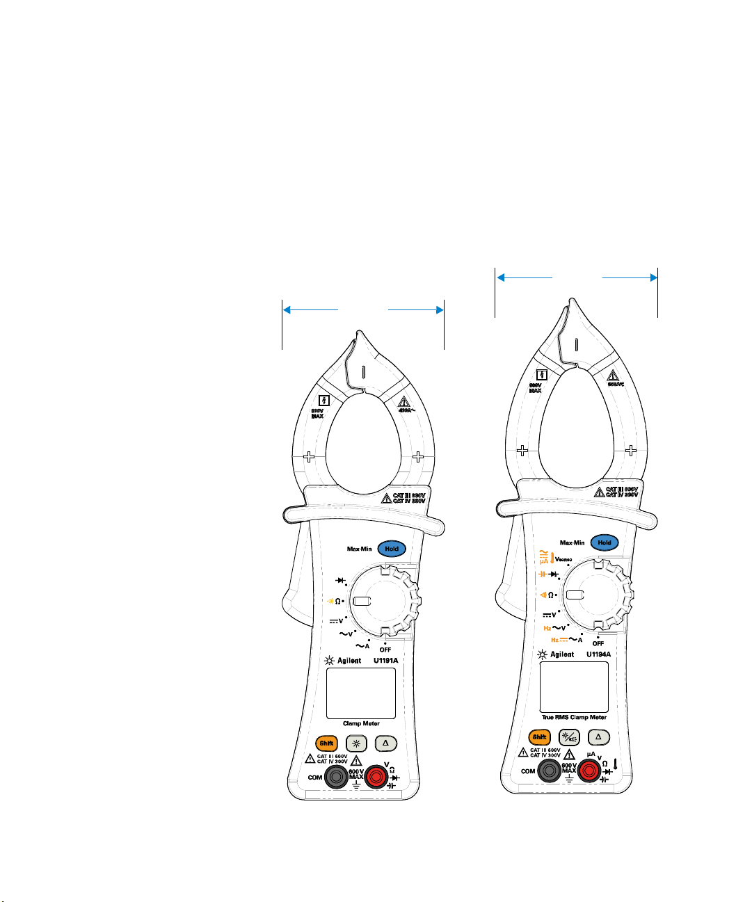
Your Clamp Meter in Brief
77.14 mm
77.14 mm
Dimensions
Front view
Introduction 1
Your Clamp Meter in Brief
U1190A Series User’s Guide 11
Page 28
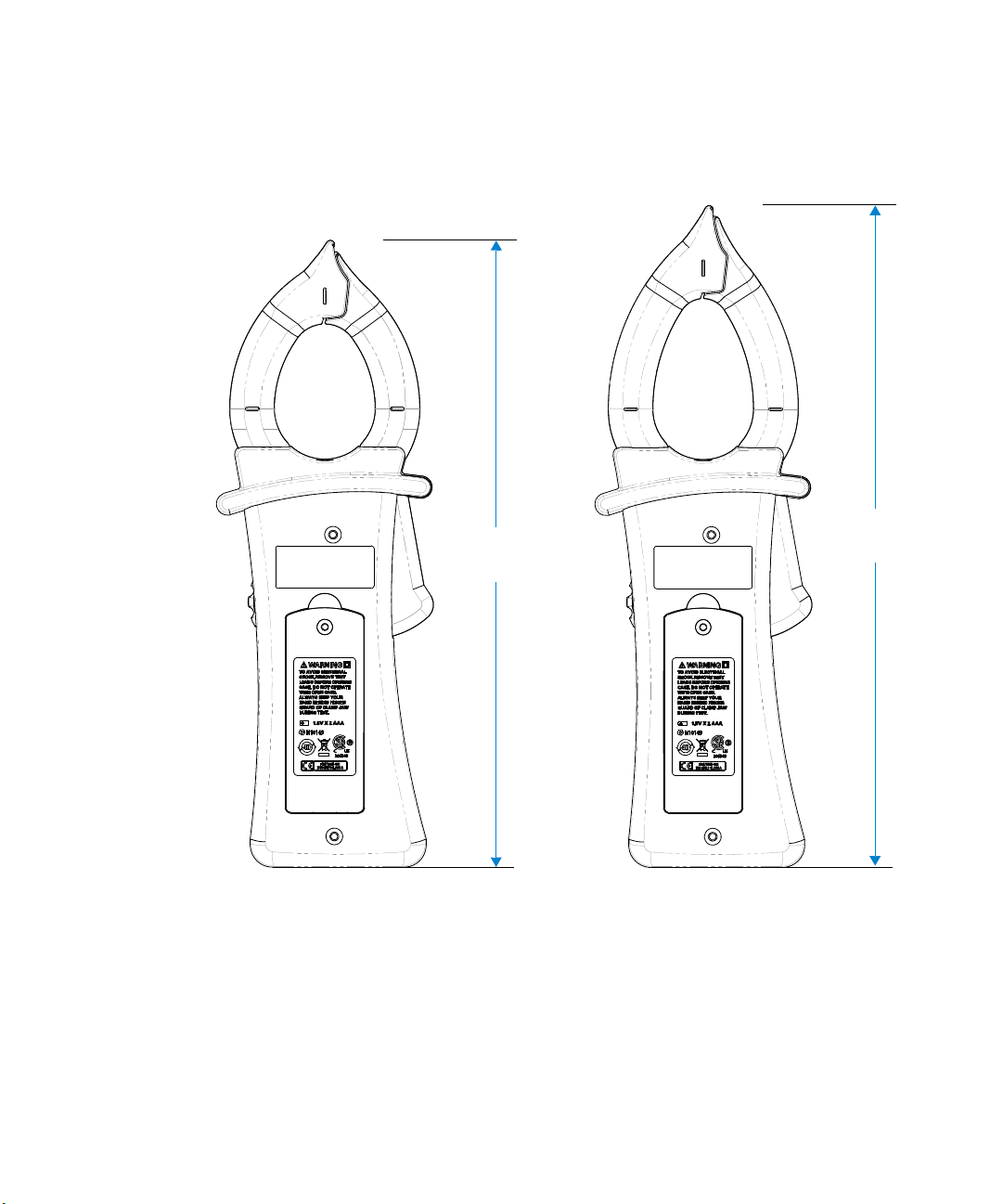
1 Introduction
225 mm
238 mm
Your Clamp Meter in Brief
Rear view
12 U1190A Series User’s Guide
Page 29

Overview
Clamp jaw
Hold/MaxMin button
Rotary switch
Display screen
Function buttons
Input terminals
Jaw markings
Introduction 1
Your Clamp Meter in Brief
Front panel
The front panel parts of your clamp meter are described in
this section.
U1190A Series User’s Guide 13
Figure 1-3 Front panel
Page 30

1 Introduction
Flashlight
Hand guard
Handle
Battery cover
Your Clamp Meter in Brief
Rear panel
The rear panel parts of your clamp meter are described in
this section.
Figure 1-4 Rear panel
14 U1190A Series User’s Guide
Page 31

Rotary switch
NOTE
WARNING
NOTE
Introduction 1
Your Clamp Meter in Brief
The measurement functions for each rotary switch position
are described in Table 1- 3 on page 16. Turning the rotary
switch changes the measurement function and resets all
other measurement options.
Some rotary switch positions have a shifted function printed in orange.
Press to switch between the shifted and primary function.
Remove the test leads from the measuring source or target before
changing the rotary switch position.
Each position of the U1191A, U1192A, U1193A, and U1194A
rotar y switches (shown in Figure 1- 3) is described in
Table 1- 3. Click the respective “Learn more” pages for more
information on each function.
U1190A Series User’s Guide 15
A list of some of the abbreviations used in Table 1-3 is given below.
•AC A: AC current measurement
•DC A: DC current measurement
•AC V: AC voltage measurement
•DC V: DC voltage measurement
•AC A: AC current measurement (up to microamperes)
•DC A: DC current measurement (up to microamperes)
Page 32

1 Introduction
Your Clamp Meter in Brief
Tab l e 1 - 3 Rotary switch functions
Legend Functions shown in the primary display U1194A U1193A U1192A U1191A Learn more on:
Off
AC A
DC A
Frequency (current path)
AC V
Frequency (voltage path)
DC V
Resistance
Continuity
Diode
Capacitance
Non-contact voltage detector
Te m p e r a t u r e
DC A
AC A
✔✔✔✔
✔✔✔✔
✔
✔✔✔
---
- page 50
✔✔✔✔
✔✔✔
- page 50
✔✔✔✔
✔✔✔✔
✔✔✔✔
✔✔✔✔
✔✔✔
✔✔✔
✔
✔
✔
---page 45
---
---
- page 43
- page 54
page 6
page 26
page 30
page 32
page 34
page 36
page 39
page 48
16 U1190A Series User’s Guide
Page 33

Keypad
Tab l e 1 - 4 Keypad functions
Introduction 1
Your Clamp Meter in Brief
The operation of each key is explained below. Pressing a key
enables a function, displays a related symbol, and emits a
beep. Turning the rotary switch to another position resets
the current operation of the key.
Click the respective “Learn more” pages for more
information on each function.
Legend
Function when pressed for:
Less than 1 second More than 1 second
Freezes the present reading in the display.
Switches between the primary and
shifted (icons printed in orange)
functions.
Turns the LCD backlight on or off. Turns the LED flashlight on or off.
U1191A only:
Turns the LCD backlight on or off.
Sets the null/relative mode. - page 57
Records the maximum, minimum, or
average value.
- page 15
- page 7
Learn more on:
page 60
page 7
and
page 8
U1190A Series User’s Guide 17
Page 34

1 Introduction
Your Clamp Meter in Brief
Display screen
The display annunciators of your clamp meter are described
in this section. See also “Measurement units” on page 20 for
a list of available measurement signs and notations.
General display annunciators
The general display annunciators of your clamp meter are
described in the table below.
Tab l e 1 - 5 General annunciators
Legend Description Learn more on:
Hazardous voltage sign for measuring voltage
30 V or overload
Hold enabled page 60
Auto-ranging enabled -
Maximum reading shown on primary display
Minimum reading shown on primary display
Averaged reading shown on primary display
Present reading shown on primary display
Relative (Null) enabled page 57
Diode test selected page 39
Audible continuity test selected page 36
DC (direct current) indication
AC (alternating current) indication
page 9
page 58
page 26
and page 32
page 26
and page 30
18 U1190A Series User’s Guide
Page 35

Introduction 1
Your Clamp Meter in Brief
Tab l e 1 - 5 General annunciators (continued)
Legend Description Learn more on:
Battery capacity indication page 5
APO (Auto Power-Off) enabled page 7
Primary measurement display -
Measuring units page 20
Overload (the reading exceeds the display
range)
-
U1190A Series User’s Guide 19
Page 36

1 Introduction
Your Clamp Meter in Brief
Measurement units
The available signs and notations for each measurement
function in your clamp meter are described in Table 1- 6.
The units listed below are applicable to the primary display
measurements of your clamp meter.
Tab l e 1 - 6 Measurement units display
Sign/Notation Description
M Mega 1E+06 (1000000)
k kilo 1E+03 (1000)
n nano 1E–09 (0.000000001)
micro 1E–06 (0.000001)
m milli 1E–03 (0.001)
mV, V Voltage units for voltage measurement
A, mA, A Ampere units for current measurement
nF, F, mF Farad units for capacitance measurement
, k, M Ohm units for resistance measurement
Hz, kHz, MHz Hertz units for frequency measurement
°C Degree Celsius, unit for temperature measurement
°F Degree Fahrenheit, unit for temperature measurement
20 U1190A Series User’s Guide
Page 37

Input terminals
WARNING
CAUTION
The terminal connections for the different measurement
functions of your clamp meter are described in the table
below. Observe the rotary switch position of your clamp
meter before connecting the test leads to the connector
terminals.
Ensure that the probe accessories are connected to the correct input
terminals for the selected measurement function before starting any
measurement.
To avoid damaging this device, do not exceed the rated input limit.
Tab l e 1 - 7 Terminal connections for different measuring functions
Introduction 1
Your Clamp Meter in Brief
Legend Functions U1194A U1193A U1192A U1191A Input terminals Overload protection
U1190A Series User’s Guide 21
AC V
Frequency
(voltage path)
DC V
Diode
Capacitance
Resistance
Continuity
Non-contact
voltage detector
Te m p e r a t u r e
✔✔✔✔
✔✔✔
-
✔✔✔✔
✔✔✔✔
✔✔✔
-
✔✔✔✔
✔✔✔✔
✔✔✔
✔
---
-
600 Vrms
600 Vrms for short
circuit current <0.4 A
600 Vrms for short
circuit current <0.1 A
Page 38

1 Introduction
Your Clamp Meter in Brief
Tab l e 1 - 7 Terminal connections for different measuring functions
Legend Functions U1194A U1193A U1192A U1191A Input terminals Overload protection
DC A
AC A
AC A
DC A
Frequency
(current path)
✔
✔
---
---
✔✔✔✔
✔
✔✔✔
---
-
CAT III 600 V
600 Arms
22 U1190A Series User’s Guide
Page 39

Cleaning Your Clamp Meter
WARNING
To avoid electrical shock or damage to the clamp meter, ensure that
the insides of the casing stay dry at all times.
Dirt or moisture in the terminals can distort readings.
Follow the steps below to clean your clamp meter.
1 Turn the clamp meter off, and remove the test leads.
2 Turn the clamp meter over, and shake out any dirt that
may have accumulated in the terminals.
Wipe the case with a damp cloth and mild detergent — do
not use abrasives or solvents. Wipe the contacts in each
terminal with a clean swab dipped in alcohol.
Introduction 1
Cleaning Your Clamp Meter
U1190A Series User’s Guide 23
Page 40

1 Introduction
Cleaning Your Clamp Meter
THIS PAGE HAS BEEN INTENTIONALLY LEFT BLANK.
24 U1190A Series User’s Guide
Page 41

U1190A Series Handheld Clamp Meter
User’s Guide
2 Making Measurements
Measuring AC or DC Current 26
Measuring AC Voltage 30
Measuring DC Voltage 32
Measuring Resistance 34
Testing for Continuity 36
Tes ti n g D io de s 39
Measuring Capacitance 43
Measuring Temperature 45
Measuring AC or DC Current (up to µA) 48
Measuring Frequency 50
This chapter describes how to take measurements with your
clamp meter.
Agilent Technologies
25
Page 42

2 Making Measurements
WARNING
CAUTION
Current
flow
Current
flow
For best accuracy during
current measurements,
align the cable with the
jaw markings.
Correct Incorrect
✔ ✘
NOTE
Measuring AC or DC Current
Measuring AC or DC Current
Ensure that the test leads are disconnected from the input terminals
when measuring current with the clamp jaws.
Ensure that the clamp meter measures only one conductor at a time.
Measuring multiple conductors may cause inaccuracy in measurement
readings due to the vector sum of currents flowing in the conductors.
Use the wire separator to separate individual wires or cables from a
mesh of wires or cables. See “Using the wire separator and hook” on
page 28 for more information.
Set up your clamp meter to measure AC current or DC
current (U1194A model only) as shown in Figure 2- 2. Clamp
the wire/cable, and read the display.
Press to measure the frequency of the AC current source (U1192A,
U1193A, and U1194A models only). See “Measuring Frequency” on
page 50 to learn more.
26 U1190A Series User’s Guide
Page 43

Making Measurements 2
3
1
2
4
5
Conductor
Measuring AC or DC Current
Figure 2-1 AC current display
Figure 2-2 Measuring AC current
U1190A Series User’s Guide 27
Page 44

2 Making Measurements
Wire separator tip
Hook
Measuring AC or DC Current
Using the wire separator and hook
Your clamp meter’s design has a wire separator and hook
feature (see Figure 2- 3) that can be used to separate
individual wires or cables for measurements from a mesh of
wires or cables.
Use the wire separator and hook to avoid touching live wires
or cables without the necessary insulation protection or
powering off the voltage or current source.
Follow the instructions below to use the wire separator and
hook feature.
Figure 2-3 Wire separator and hook design
28 U1190A Series User’s Guide
Page 45

Making Measurements 2
Mesh of wires or cables
Measuring AC or DC Current
1 Open the clamp jaw slightly to reveal the wire separator
tip. Use the wire separator tip to locate the desired wire
or cable.
2 Separate the wire or cable by hooking it in the clamp jaw
securely and pulling it back.
3 Close the clamp jaw to secure the wire or cable, and read
the measurement.
U1190A Series User’s Guide 29
Page 46

2 Making Measurements
NOTE
NOTE
NOTE
Measuring AC Voltage
Measuring AC Voltage
Reversing the leads will produce a negative reading, but it will not damage
the clamp meter.
Set up your clamp meter to measure AC voltage as shown in
Figure 2- 5. Probe the test points, and read the display.
For U1193A and U1194A models:
AC voltage measurements measured with this clamp meter are returned
as true RMS (root mean square) readings. These readings are accurate for
sinusoidal waves. For non-sinusoidal waveforms, please refer to the
“Specification Assumptions” on page 64.
Figure 2-4 AC voltage display
Press to measure the frequency of the AC voltage source (U1192A,
U1193A, and U1194A models only). See “Measuring Frequency” on
page 50 to learn more.
30 U1190A Series User’s Guide
Page 47

Making Measurements 2
2
4
AC
Voltage source
1
3
Measuring AC Voltage
Figure 2-5 Measuring AC voltage
U1190A Series User’s Guide 31
Page 48

2 Making Measurements
NOTE
Measuring DC Voltage
Measuring DC Voltage
Set up your clamp meter to measure DC voltage as shown in
Figure 2- 7. Probe the test points, and read the display.
This clamp meter displays DC voltage values as well as their polarity.
Negative DC voltages will return a negative sign on the left of the display.
Figure 2-6 DC voltage display
32 U1190A Series User’s Guide
Page 49

Making Measurements 2
DC
3
Voltage source
1
2
Measuring DC Voltage
Figure 2-7 Measuring DC voltage
U1190A Series User’s Guide 33
Page 50

2 Making Measurements
CAUTION
NOTE
NOTE
Measuring Resistance
Measuring Resistance
Set up your clamp meter to measure resistance as shown in
Figure 2- 9. Probe the test points, and read the display.
To avoid possible damage to your clamp meter or to the equipment
under test, disconnect the circuit power and discharge all high-voltage
capacitors before measuring resistance.
Resistance (opposition to the current flow) is measured by sending a small
current out through the test leads to the circuit under test. Because this
current flows through all possible paths between the leads, the resistance
reading represents the total resistance of all paths between the leads.
Resistance is measured in ohms ().
34 U1190A Series User’s Guide
Figure 2-8 Resistance display
Keep the following in mind when measuring resistance.
• The test leads can add 0.1 to 0.2 of error to resistance
measurements. To test the leads, touch the probe tips together and
read the resistance of the leads.
• Because the clamp meter’s test current flows through all possible
paths between the probe tips, the measured value of a resistor in a
circuit is often different from the resistor’s rated value.
• The resistance function can produce enough voltage to forward-bias
silicon diodes or transistor junctions, causing them to conduct.
Page 51

Making Measurements 2
3
Resistor
1
2
Measuring Resistance
Figure 2-9 Measuring resistance
U1190A Series User’s Guide 35
Page 52

2 Making Measurements
CAUTION
NOTE
Testing for Continuity
Testing for Continuity
Set up your clamp meter to test for continuity as shown in
Figure 2- 12. Probe the test points, and read the display.
To avoid possible damage to your clamp meter or to the equipment
under test, disconnect the circuit power and discharge all high-voltage
capacitors before testing for continuity.
Continuity is the presence of a complete path for current flow. The
continuity test features a beeper that sounds and a backlight that flashes
as long as a circuit is complete. The audible and visual alert allows you to
perform quick continuity tests without having to watch the display.
Press to switch between resistance measurement, or
continuity test. See Figure 2- 12 to learn more.
36 U1190A Series User’s Guide
Figure 2-10 Open continuity display
Figure 2-11 Closed continuity display
Page 53

Making Measurements 2
NOTE
Testing for Continuity
• You can set the beeper to sound and the backlight to flash as a
continuity indication whether the circuit-under-test is less than (short)
the threshold resistance.
• The continuity function detects intermittent shorts lasting as short as 1
ms. A brief short causes the multimeter to emit a short beep and flash.
• You can enable or disable the visual alert via the Setup menu. See
“Changing the continuity visual alert” on page 37 for more information.
Changing the continuity visual alert
You can set the backlight to flash along with the beeper
sound as a continuity indication whether the
circuit- under-test is less than the threshold resistance.
Follow the steps below to enable or disable the continuity
visual alert.
1 Press and hold while powering on the clamp meter to
enter the Setup menu.
2 Press again. The continuity visual alert ( ) is the
fourth Setup item shown.
3 Press to make changes to the continuity visual alert.
Press or to enable or to disable the continuity
visual alert (the backlight turns on or off).
4 Press to save the changes, or press to discard
the changes and proceed to the next Setup item.
5 Cycle the clamp meter’s power to exit the Setup menu.
U1190A Series User’s Guide 37
Page 54

2 Making Measurements
4
1
3
CLOSED
OPEN
2
Testing for Continuity
Figure 2-12 Testing for continuity
38 U1190A Series User’s Guide
Page 55

Testing Dio d e s
CAUTION
NOTE
NOTE
Making Measurements 2
Testing Diodes
Set up your clamp meter to test diodes as shown in
Figure 2- 15. Probe the test points, and read the display.
To avoid possible damage to your clamp meter or to the equipment
under test, disconnect the circuit power and discharge all high-voltage
capacitors before testing diodes.
• Use the diode test to check diodes, transistors, silicon controlled
rectifiers (SCRs), and other semiconductor devices. A good diode
allows current to flow in one direction only.
• This test sends a current through a semiconductor junction, and then
measures the junction’s voltage drop.
• Connect the red test lead to the positive terminal (anode) of the diode
and the black test lead to the negative terminal (cathode). The cathode
of a diode is indicated with a band.
U1190A Series User’s Guide 39
Figure 2-13 Diode display
Your clamp meter can display the forward-bias of a diode up to
approximately 1.8 V. The forward-bias of a typical diode is within the range
of 0.3 V to 0.8 V; however, the reading can vary depending on the
resistance of other pathways between the probe tips.
Page 56

2 Making Measurements
NOTE
Testing Diodes
If the beeper is enabled during diode test, the clamp meter will beep briefly
for a normal junction and sound continuously for a shorted junction.
Reverse the probes (as shown in Figure 2- 16) and measure
the voltage across the diode again. Assess the diode
according to the following guidelines:
• A diode is considered good if the clamp meter displays
in reverse- bias mode.
• A diode is considered shorted if the clamp meter
displays approximately 0 V in both forward and
reverse- bias modes, and the clamp meter beeps
continuously.
• A diode is considered open if the clamp meter displays
in both forward- and reverse- bias modes.
Figure 2-14 Open diode display
40 U1190A Series User’s Guide
Page 57

Making Measurements 2
3
Forward-bias
diode
1
2
Testing Diodes
Figure 2-15 Testing forward-bias diode
U1190A Series User’s Guide 41
Page 58

2 Making Measurements
3
Reverse-bias
diode
1
2
Testing Diodes
Figure 2-16 Testing reverse-bias diode
42 U1190A Series User’s Guide
Page 59

Measuring Capacitance
CAUTION
NOTE
NOTE
This measurement function is applicable for U1192A,
U1193A, and U1194A models only.
Set up your clamp meter to measure capacitance as shown
in Figure 2- 18. Probe the test points, and read the display.
To avoid possible damage to the clamp meter or to the equipment
under test, disconnect circuit power and discharge all high-voltage
capacitors before measuring capacitance. Use the DC voltage function
to confirm that the capacitor is fully discharged.
The clamp meter measures capacitance by charging the capacitor with a
known current for a known period of time, measuring the resulting voltage,
and then calculating the capacitance.
Making Measurements 2
Measuring Capacitance
U1190A Series User’s Guide 43
Figure 2-17 Capacitance display
For measuring capacitance values greater than 1000 F, discharge the
capacitor first, then select a suitable range for measurement. This will
speed up the measurement time and also ensure that the correct
capacitance value is obtained.
Page 60

2 Making Measurements
2
4
Capacitor
1
3
Measuring Capacitance
Figure 2-18 Measuring capacitance
44 U1190A Series User’s Guide
Page 61

Measuring Temperature
WARNING
CAUTION
NOTE
This measurement function is applicable for the U1194A
model only.
Set up your clamp meter to measure temperature as shown
in Figure 2- 20. Probe the test points, and read the display.
Do not connect the thermocouple to electrically live circuits. Doing
so will potentially cause fire or electric shock.
Do not bend the thermocouple leads at sharp angles. Repeated
bending over a period of time can break the leads.
• The clamp meter uses the type-K thermocouple probe (included in the
• The approximate ambient temperature (cold-junction compensation) is
• Shorting the terminal to the terminal will display the
Making Measurements 2
Measuring Temperature
standard shipped items of a U1194A model) for measuring temperature.
shown on the display when you have an open thermocouple. The open
thermocouple message may be due to a broken (open) probe or
because no probe is installed into the input jacks of the clamp meter.
temperature at the clamp meter’s terminals.
U1190A Series User’s Guide 45
Figure 2-19 Temperature display
Page 62

2 Making Measurements
CAUTION
NOTE
Measuring Temperature
Changing the default temperature unit
Follow the steps below to change the temperature unit
between Celsius (°C) or Fahrenheit (°F).
1 Press and hold and while powering on the clamp
meter to enter the temperature unit selection menu.
2 Press to make changes to the temperature unit.
Press or to change the temperature unit
(°C or °F).
3 Press to save the changes.
4 Cycle the clamp meter’s power to exit the temperature
unit selection menu.
Always set the temperature unit display per the official requirements
and in compliance with the national laws of your region.
The bead-type thermocouple probe is suitable for measuring temperatures
from –40 °C to 204 °C (399 °F) in Teflon-compatible environments. Do not
immerse this thermocouple probe in any liquid. For best results, use a
thermocouple probe designed for each specific application — an
immersion probe for liquid or gel, and an air probe for air measurement.
Observe the following measurement techniques:
• Clean the surface to be measured, and ensure that the probe is
securely touching the surface. Remember to disable the applied power.
• When measuring above ambient temperatures, move the thermocouple
along the surface until you get the highest temperature reading.
• When measuring below ambient temperatures, move the thermocouple
along the surface until you get the lowest temperature reading.
46 U1190A Series User’s Guide
• Place the clamp meter in the operating environment for at least 1 hour
as the clamp meter is using a non-compensation transfer adapter with
miniature thermal probe.
Page 63

Making Measurements 2
2
4
1
3
K-type
thermocouple
probe
Heat source
Measuring Temperature
Figure 2-20 Measuring the surface temperature
U1190A Series User’s Guide 47
Page 64

2 Making Measurements
WARNING
CAUTION
Measuring AC or DC Current (up to µA)
Measuring AC or DC Current (up to µA)
Never attempt an in-circuit current measurement where the
open-circuit potential to earth is greater than 1000 V. Doing so will
cause damage to the clamp meter and possible electric shock or
personal injury.
• To avoid possible damage to the clamp meter or to the equipment
under test, use the proper terminals, function, and range for your
measurement. Use the clamp jaw for currents above 600 µA.
To measure current, you must open the circuit under test, then place
•
the clamp meter in series with the circuit.
across (in parallel with) any circuit or component when the leads
are plugged into the current terminals.
• Placing the probes across (in parallel with) a powered circuit when
a lead is plugged into a current terminal can damage the circuit you
are testing. This happens because the resistance through the clamp
meter's current terminals is very low, resulting in a short circuit.
Never place the probes
48 U1190A Series User’s Guide
This measurement function is applicable for the U1194A
model only.
Set up your clamp meter to measure AC or DC current (up
to A) as shown in Figure 2- 22. Probe the test points, and
read the display.
Figure 2-21 DC current display
Page 65

Making Measurements 2
AC
2
4
1
Voltage source
DC
Voltage source
LOAD
3
LOAD
Measuring AC or DC Current (up to µA)
Figure 2-22 Measuring AC/DC current (up to µA)
U1190A Series User’s Guide 49
Page 66

2 Making Measurements
WARNING
NOTE
Rise Time Fall Time
+ Width – Width
Period
90%
50%
10%
Measuring Frequency
Measuring Frequency
Never measure the frequency where the voltage or current level
exceeds the specified range.
This measurement function is applicable for U1192A,
U1193A, and U1194A models only.
Your clamp meter allows simultaneous monitoring of real-
time voltage or current with frequency measurements.
• Measuring the frequency of a signal helps detect the presence of
harmonic currents in neutral conductors and determines whether these
neutral currents are the result of unbalanced phases or non-linear
loads.
• Frequency is the number of cycles a signal completes each second.
Frequency is defined as 1/Period. Period is defined as the time
between the middle threshold crossings of two consecutive,
like-polarity edges, as shown in the figure below.
50 U1190A Series User’s Guide
• The clamp meter measures the frequency of a voltage or current signal
by counting the number of times the signal crosses a threshold level
within a specified period of time.
Page 67

Making Measurements 2
3
1
2
4
Conductor
Measuring Frequency
Figure 2-23 Frequency display
Figure 2-24 Measuring frequency
U1190A Series User’s Guide 51
Page 68

2 Making Measurements
Measuring Frequency
THIS PAGE HAS BEEN INTENTIONALLY LEFT BLANK.
52 U1190A Series User’s Guide
Page 69

U1190A Series Handheld Clamp Meter
User’s Guide
3 Clamp Meter Features
Detecting AC Voltage Presence (Vsense) 54
Making Relative Measurements (Null) 57
Capturing Maximum and Minimum Values (Max.Min) 58
Freezing the Display (Hold) 60
The chapter describes the additional features available in
your clamp meter.
Agilent Technologies
53
Page 70

3Clamp Meter Features
WARNING
CAUTION
NOTE
Detecting AC Voltage Presence (Vsense)
Detecting AC Voltage Presence (Vsense)
• You are advised to test on a known live circuit within the rated AC
voltage range of this product before and after each use to ensure
that the Vsense detector works.
• Voltage could still be present even if there is no Vsense alert
indication. Do not rely on the Vsense detector with shielded wire.
Never touch live voltage or conductor without the necessary
insulation protection or power off the voltage source.
• The Vsense detector may be affected by differences in socket
design, insulation thickness, and insulation type.
You are advised to measure voltage by using test leads through the
AC V or DC V function after using the Vsense function, even if there is
no alert indication.
This measurement function is applicable for U1192A,
U1193A, and U1194A models only.
54 U1190A Series User’s Guide
The Vsense detector is a non- contact voltage detector that
detects the presence of AC voltages nearby.
Set up your clamp meter to enable the Vsense function as
shown in Figure 3-3.
If the presence of AC voltage is sensed, the clamp meter’s beeper will
sound. The audible alert allows you to easily sense nearby AC voltage
presence.
No resolution and accuracy of voltage measurement will be displayed in
this mode.
Page 71

Clamp Meter Features 3
NOTE
Detecting AC Voltage Presence (Vsense)
• Place the top of the clamp meter close to a conductor when sensing for
AC voltages (as low as 24 V in the Hi.SE setting).
• The low sensitivity setting can be used on flush mounted wall sockets
or outlets and various power strips or cords.
• The high sensitivity setting allows for AC voltage sensing on other
styles of recessed power connectors or sockets where the actual AC
voltage is recessed within the connector itself.
Press to toggle the Vsense detector’s sensitivity between
Hi.SE (high sensitivity) or Lo.SE (low sensitivity).
Figure 3-1 Vsense (high sensitivity) display
Figure 3-2 Vsense (low sensitivity) display
U1190A Series User’s Guide 55
Page 72

3Clamp Meter Features
3
4
Voltage source
AC
2
1
Detecting AC Voltage Presence (Vsense)
Figure 3-3 Detecting voltage presence
56 U1190A Series User’s Guide
Page 73

Making Relative Measurements (Null)
NOTE
When making Null measurements, also called relative, each
reading is the difference between a stored (measured) null
value and the input signal.
One possible application is to increase the accuracy of a
resistance measurement by nulling the test lead resistance.
Nulling the leads is also particularly important prior to
making capacitance measurements.
1 To activate the relative mode, press the key. The
measurement value at the time, when Null is enabled, is
stored as the reference value.
Clamp Meter Features 3
Making Relative Measurements (Null)
Figure 3-4 Null display
2 To disable the Null function, press again.
For any measurement function, you can directly measure and
store the null value by pressing with the test leads open
(nulls the test lead capacitance), shorted (nulls the test lead
resistance), or across a desired null value circuit.
• In resistance measurement, the clamp meter will read a non-zero value
even when the two test leads are in direct contact because of the
resistance of these leads. Use the Null function to zero-adjust the
display.
• For DC voltage measurements, the thermal effect will influence the
accuracy of the measurements. Short the test leads and press
when the displayed value is stable to zero-adjust the display.
U1190A Series User’s Guide 57
Page 74

3Clamp Meter Features
Capturing Maximum and Minimum Values (Max.Min)
Capturing Maximum and Minimum Values (Max.Min)
The Max.Min operation stores the maximum, minimum, and
average input values during a series of measurements.
When the input goes below the recorded minimum value or
above the recorded maximum value, the clamp meter beeps
and records the new value. The clamp meter also calculates
an average of all readings taken since the Max.Min mode
was activated.
From the clamp meter’s display, you can view the following
statistical data for any set of readings:
• Max: highest reading since the Max.Min function was
enabled
• Min: lowest reading since the Max.Min function was
enabled
• Avg: average or mean of all readings since the Max.Min
function was enabled
• MaxMinAvg: present reading (actual input signal value)
1 Press and hold for more than 1 second to enable the
Max.Min operation.
2 Press again to cycle through the Max, Min, Avg, or
present (MaxMinAvg) input values.
3 Press for more than 1 second to disable the Max.Min
function.
Figure 3-5 Max.Min display
58 U1190A Series User’s Guide
Page 75

Clamp Meter Features 3
NOTE
Capturing Maximum and Minimum Values (Max.Min)
If an overload is recorded, the averaging function will be stopped. is
shown in place of the average value.
This mode is useful for capturing intermittent readings,
recording minimum and maximum readings unattended, or
recording readings while equipment operation keeps you
from observing the clamp meter display.
The true average value displayed is the arithmetic mean of
all readings taken since the start of recording. The average
reading is useful for smoothing out unstable inputs,
calculating power consumption, or estimating the percentage
of time a circuit is active.
U1190A Series User’s Guide 59
Page 76

3Clamp Meter Features
Freezing the Display (Hold)
Freezing the Display (Hold)
To freeze the display for any function, press the key.
Figure 3-6 Hold display
Press again to disable this function.
60 U1190A Series User’s Guide
Page 77

U1190A Series Handheld Clamp Meter
User’s Guide
4 Characteristics and Specifications
Product Characteristics 62
Specification Assumptions 64
Measurement Category 65
Measurement category definition 65
Electrical Specifications 66
DC specifications 66
AC specifications 68
Capacitance specifications 69
Temperature specifications 70
Frequency specifications 71
Frequency sensitivity specifications 71
Display update rate (approximate) 72
This chapter lists the characteristics, assumptions, and
specifications of the U1191A, U1192A, U1193A, and U1194A
handheld clamp meters.
Agilent Technologies
61
Page 78

4 Characteristics and Specifications
NOTE
Product Characteristics
Product Characteristics
Product characteristics specified in the table below are applicable for
U1191A, U1192A, U1193A, and U1194A models unless stated otherwise.
POWER SUPPLY
Battery type:
• 2 × 1.5 V AAA Alkaline battery (IEC LR03)
Battery life:
• 200 hours typical (based on new Alkaline batteries, for continuous DC voltage
measurement, with backlight disabled)
• 40 hours typical (based on new Alkaline batteries, with backlight enabled)
• Low battery indicator will flash when the battery voltage drops below 2.5 V
(approximately)
POWER CONSUMPTION
• 9 mVA maximum (based on new Alkaline batteries, for continuous DC voltage
measurement, with backlight disabled)
• 42 mVA maximum (based on new Alkaline batteries, for continuous DC voltage
measurement, with backlight enabled)
DISPLAY
Liquid crystal display (LCD) with backlight (maximum reading of 6000 counts)
OPERATING ENVIRONMENT
• Operating temperature from –10 °C to 50 °C, 0% to 80% RH
• Up to 80% RH for temperatures up to 30 °C, decreasing linearly to 50% RH at
50 °C
• Altitude up to 2000 meters
• Pollution degree 2
STORAGE COMPLIANCE
–40 °C to 60 °C, 40% to 80% RH (without batteries)
SAFETY COMPLIANCE
• IEC 61010-1:2001/EN 61010-1:2001
• IEC 61010-2-032:2002/EN 61010-2-032:2002
• CAN/CSA-C22.2 No. 61010-1-04
• CAN/CSA-C22.2 No. 61010-2-032-04
• ANSI/UL Std. No. 61010-1:2004
62 U1190A Series User’s Guide
Page 79

Characteristics and Specifications 4
Product Characteristics
MEASUREMENT CATEGORY
CAT III 600 V and CAT IV 300 V (for digital multimeter and current clamp portions)
ELECTROMAGNETIC COMPATIBILITY (EMC)
• IEC61326-1:2005/EN61326-1:2006
• Canada: ICES/NMB-001: Issue 4, June 2006
• Australia/New Zealand: AS/NZS CISPR 11:2004
TEMPERATURE COEFFICIENT
0.1 × (specified accuracy) / °C (from 0 °C to 18 °C, or 28 °C to 50 °C)
COMMON MODE REJECTION RATIO (CMRR)
>60 dB at DC, 60 Hz in the AC V function
>120 dB at DC, 50/60 Hz in the DC V function
NORMAL MODE REJECTION RATION (NMRR)
>60 dB at 50/60 Hz
DIMENSIONS (W × H × D)
• U1191A/U1192A: 77.14 × 225 × 38.56 mm
• U1193A/U1194A: 77.14 × 238 × 38.56 mm
WEIGHT
• U1191A/U1192A: 320 grams (with batteries)
• U1193A: 334 grams (with batteries)
• U1194A: 348 grams (with batteries)
MAXIMUM CONDUCTOR SIZE
• U1191A/U1192A: Up to 27 mm diameter for 500 MCM cable
• U1193A/U1194A: Up to 35 mm diameter for 750 MCM cable
MAXIMUM JAW OPENING
• U1191A/U1192A: Up to 31 mm
• U1193A/U1194A: Up to 37 mm
U1190A Series User’s Guide 63
Page 80

4 Characteristics and Specifications
Specification Assumptions
WARRANTY
Please refer to http://www.agilent.com/go/warranty_terms
• Three years for the product
• Three months for the product’s standard accessories, unless otherwise
specified
• Please take note that for the product, the warranty does not cover:
• Damage from contamination
• Normal wear and tear of mechanical components
• Manuals and batteries
CALIBRATION CYCLE
One year
Specification Assumptions
• Accuracy is given as ± (% of reading + counts of least
significant digit) at 23 °C ± 5 °C, with relative humidity
less than 80% RH.
• AC V and AC A specifications for U1193A and U1194A
models are AC coupled, true RMS, and are valid from 5%
of range to 100% of range.
• The crest factor may be up to 3.0 at full- scale (4000
counts)
• For non- sinusoidal waveforms, add (2% reading + 2% full
scale) typically.
• In the EMC RF field of 3 V/m, the total accuracy is
specified as the specified accuracy ± 30 digits for all
functions.
64 U1190A Series User’s Guide
Page 81

Measurement Category
The Agilent U1190A Series Handheld Clamp Meters have a
safety rating of CAT III, 600 V and CAT IV, 300 V.
Measurement category definition
Measurement CAT I are for measurements performed on
circuits not directly connected to the AC mains. Examples
are measurements on circuits not derived from the AC mains
and specially protected (internal) mains- derived circuits.
Measurement CAT II are measurements performed on
circuits directly connected to a low- voltage installation.
Examples are measurements on household appliances,
portable tools, and similar equipment.
Measurement CAT III are measurements performed in
building installations. Examples are measurements on
distribution boards, circuit- breakers, wiring, including cables,
bus- bars, junction boxes, switches, socket outlets in the fixed
installation, and equipment for industrial use, and some
other equipment including stationary motors with permanent
connection to the fixed installation.
Characteristics and Specifications 4
Measurement Category
Measurement CAT IV are measurements performed at the
source of low-voltage installations. Examples are electricity
meters and measurements on primary over current
protection devices and ripple control units.
U1190A Series User’s Guide 65
Page 82

4 Characteristics and Specifications
NOTE
Electrical Specifications
Electrical Specifications
Specification assumptions are given on page 64.
DC specifications
Tab l e 4 - 1 DC specifications
Function Range Resolution
U1191A U1192A U1193A U1194A (where applicable)
Voltage
Notes for DC voltage specifications:
1 Overload protection: 600 Vdc.
2 Input impedance: 10 M (nominal) in parallel with <100 pF
Resistance
Notes for resistance specifications:
1 Overload protection: 600 Vrms for short circuits with <0.1 mA current
2 Maximum open voltage is <1.4 V
3 The accuracy is specified after the Null function is used to subtract the test lead resistance and thermal effect (by shorting
the test leads).
60.00 V 0.01 V - 0.5% + 3 0.5% + 3 0.5% + 3 - -
600.0 V 0.1 V 0.5% + 3 0.5% + 3 0.5% + 3 0.5% + 3 - -
600.0 0.1 0.8% + 5 0.8% + 5 0.8% + 5 0.8% + 5 95 A1.4 V
6.000 k 0.001 k 0.8% + 3 0.8% + 3 0.8% + 3 0.8% + 3 95 A1.4 V
60.00 k 0.01 k - 0.8% + 3 0.8% + 3 0.8% + 3 95 A0.7 V
Accuracy Test current
Open
voltage
66 U1190A Series User’s Guide
Page 83

Tab l e 4 - 1 DC specifications (continued)
Characteristics and Specifications 4
Electrical Specifications
Function Range Resolution
Accuracy Test current
U1191A U1192A U1193A U1194A (where applicable)
Continuity 600.0 0.1 0.8% + 5 0.8% + 5 0.8% + 5 0.8% + 5 95 A 1.4 V
Notes for continuity specifications:
1 Overload protection: 600 Vrms for short circuits with <0.1 A current
2 Built-in buzzer beeps continuously when the resistance measured is less than 30 . Resistance measurements above
200 are considered open. For resistance measured between 30 and 200 (30 reading 200 ), the built-in
buzzer may beep depending on the device-under-test.
3 Continuity indicator: 2.7 kHz tone buzzer
Diode 1.500 V 0.001 V 1.0% + 3 1.0% + 3 1.0% + 3 1.0% + 3 0.3 mA 1.8 V
Notes for diode specifications:
1 Overload protection: 600 Vrms for short circuits with <0.4 mA current
2 Built-in buzzer beeps continuously when the voltage measured is less than 100 mV and beeps once for forward-biased
diode or semiconductor junctions measured between 0.3 V and 0.8 V (0.3 V reading 0.8 V).
60.00 µA 0.01 µA - - - 1.0% + 5 - -
600.0 µA 0.1 µA - - - 1.0% + 5 - -
Current
60.00 A 0.01 A - - - 2.0% + 5 - -
600.0 A 0.1 A - - - 2.0% + 5 - -
Open
voltage
Notes for DC current specifications:
1 60 A to 600 A ranges are for current clamp measurements.
2 60 µA to 600 µA ranges are for digital multimeter measurements.
3 Overload protection for 60 A to 600 A range: 600 Arms
4 Input impedance for 60 µA to 600 µA range: 4.2 k
5 Position error: 1% from reading
6 The accuracy is specified after the Null function is used to subtract the test lead resistance and thermal effect (by shorting
the test leads).
U1190A Series User’s Guide 67
Page 84

4 Characteristics and Specifications
Electrical Specifications
AC specifications
AC voltage specifications
Tab l e 4 - 2 AC voltage specifications
Accuracy
Range Resolution
60.00 V 0.01 V - 1.2% + 5 1.2% + 5 1.2% + 5 10 M
600.0 V 0.1 V 1.2% + 5 1.2% + 5 1.2% + 5 1.2% + 5 10 M
Notes for AC voltage specifications:
1 Overload protection: 600 Vrms
2 Input impedance: 10 M (nominal) in parallel with <100 pF
3 Frequency response: 45 Hz to 500 Hz (sinusoidal waveform)
4 AC conversion type:
• U1191A and U1192A: Average sensing, RMS indication
• U1193A and U1194A: RMS sensing, RMS indication
U1191A U1192A U1193A U1194A
45 Hz to 500 Hz
Input
impedance
AC current specifications
Tab l e 4 - 3 AC current specifications
Accuracy
Range Resolution
60.00 µA0.01 µA------1.0% + 51.0% + 5
600.0 µA0.1 µA ------1.0% + 51.0% + 5
60.00 A 0.01 A - - 2.0% + 5 3.0% + 5 2.0% + 5 3.0% + 5 2.0% + 5 3.0% + 5
400.0 A0.1 A2.0% + 53.0% + 52.0% + 53.0% + 5----
68 U1190A Series User’s Guide
U1191A U1192A U1193A U1194A
45 Hz to
65 Hz
65 Hz to
500 Hz
45 Hz to
65 Hz
65 Hz to
500 Hz
45 Hz to
65 Hz
65 Hz to
500 Hz
45 Hz to
65 Hz
65 Hz to
500 Hz
Page 85

Tab l e 4 - 3 AC current specifications (continued)
Characteristics and Specifications 4
Electrical Specifications
Accuracy
Range Resolution
600.0 A0.1 A----2.0% + 53.0% + 52.0% + 53.0% + 5
Notes for AC current specifications:
1 Overload protection:
• U1191A and U1192A: 400 Arms
• U1193A and U1194A: 600 Arms
2 Input impedance for 60 µA to 600 µA range: 4.2 k
3 Frequency response: 45 Hz to 500 Hz (sinusoidal waveform)
4 Position error: 1% from reading
5 AC conversion type:
• U1191A and U1192A: Average sensing, RMS indication
• U1193A and U1194A: RMS sensing, RMS indication
6 For non-sinusoidal waveform, add an additional accuracy of (2% of reading + 2% of full scale) typically for
crest factor 3.0.
U1191A U1192A U1193A U1194A
45 Hz to
65 Hz
65 Hz to
500 Hz
45 Hz to
65 Hz
65 Hz to
500 Hz
45 Hz to
65 Hz
65 Hz to
500 Hz
45 Hz to
65 Hz
65 Hz to
500 Hz
Capacitance specifications
Tab l e 4 - 4 Capacitance specifications
Range Resolution
Accuracy
U1191A U1192A U1193A U1194A
600.0 F0.1 F - 2.0% + 4 2.0% + 4 2.0% + 4 2 times/second
6.00 mF 0.001 mF - 2.0% + 4 2.0% + 4 2.0% + 4 1 time/9 seconds
Notes for capacitance specifications:
1 This function is only applicable for U1192A, U1193A, and U1194A models.
2 Overload protection: 600 Vrms for short circuits with <0.1 mA current
3 The accuracy of for all ranges is specified based on a film capacitor or better, and after the Null function is used to subtract
the test lead resistance and thermal effect (by opening the test leads).
Measuring rate
(at full scale)
U1190A Series User’s Guide 69
Page 86

4 Characteristics and Specifications
Electrical Specifications
Temperature specifications
Tab l e 4 - 5 Temperature specifications
Thermal type Range Resolution
–40 °C to 400 °C 0.1 °C 1.0% + 2.0 °C
K
400 °C to 1200 °C 1.0 °C 1.0% + 2.0 °C
–40 °F to 752 °F 0.1 °F 1.0% + 3.6 °F
K
752 °F to 2192 °F 1.0 °F 1.0% + 3.6 °F
Notes for temperature specifications:
1 This function is only applicable for the U1194A model.
2 The specification above is specified after the multimeter has been left stationary in the same operating environment for
1 hour at least. If the unit is exposed during storage in a high humidity (condensing) environment, ensure that the
multimeter has been in the same operating environment for 2 hours at least.
3 The accuracy does not include the tolerance of the thermocouple probe.
4 Do not allow the temperature sensor to contact a surface that is energized above 30 Vrms or 60 V DC. Such voltages pose
a shock hazard.
5 The temperature calculation is specified according to the safety standards of EN/IEC-60548-1 and NIST175.
6 The accuracy specification assumes the surrounding temperature is stable with ±1 °C. For the surrounding temperature
changes of ±3 °C, the rated accuracy applies after two hours.
Accuracy
U1194A
70 U1190A Series User’s Guide
Page 87

Frequency specifications
Tab l e 4 - 6 Frequency specifications
Characteristics and Specifications 4
Electrical Specifications
Range Resolution
Accuracy
U1191A U1192A U1193A U1194A
99.99 Hz 0.01 Hz 0.5% + 3 0.5% + 3 0.5% + 3 0.5% + 3
999.9 Hz 0.1 Hz 0.5% + 3 0.5% + 3 0.5% + 3 0.5% + 3
9.999kHz 0.001 kHz 0.5% + 3 0.5% + 3 0.5% + 3 0.5% + 3
99.99 kHz 0.01 kHz 0.5% + 3 0.5% + 3 0.5% + 3 0.5% + 3
Notes for frequency specifications:
1 This function is only applicable for U1192A, U1193A, and U1194A models.
2 Overload protection: 600 V
Minimum input
Frequency sensitivity specifications
For voltage measurements
Tab l e 4 - 7 Frequency sensitivity and trigger-level specifications for voltage measurements
Input range Minimum sensitivity (RMS sine wave)
Maximum input for specified accuracy 10 Hz to 10 kHz 10 kHz to 100 kHz
frequency
10 Hz
60 V6.0 V30 V
600 V 60 V 60 V
Notes for frequency sensitivity specifications for voltage measurements:
1 This function is only applicable for U1192A, U1193A, and U1194A models.
2 Maximum input for specified accuracy, refer to “AC specifications” on page 68.
U1190A Series User’s Guide 71
Page 88

4 Characteristics and Specifications
Electrical Specifications
For current measurements
Tab l e 4 - 8 Frequency sensitivity and trigger level specifications for current measurements
Input range Minimum sensitivity (RMS sine wave)
Maximum input for specified accuracy 45 Hz to 1 kHz
60 A 6.0A
600 A 60 A
Notes for frequency sensitivity specifications for voltage measurements:
1 This function is only applicable for U1192A, U1193A, and U1194A models.
2 Maximum input for specified accuracy, refer to “AC specifications” on page 68.
Display update rate (approximate)
Tab l e 4 - 9 Display update rate (approximate)
(6 mF)
Times/second
2 times/1 second
1 time/9 seconds
(600 F)
(6 mF)
2 times/1 second
(600 F)
1 time/9 seconds
(6 mF)
Function
AC V 3 3 3 3
DC V 3 3 3 3
2222
Diode 3 3 3 3
Capacitance -
Te m p e r a t u r e - - - 2
DC A (A or A) - - - 3
AC A (A or A)3333
Frequency - 3 (>10 Hz) 3 (>10 Hz) 3 (>10 Hz)
U1191A U1192A U1193A U1194A
2 times/1 second
(600 F)
1 time/9 seconds
72 U1190A Series User’s Guide
Page 89

www.agilent.com
Contact us
To obtain service, warranty, or technical
assistance, contact us at the following
phone or fax numbers:
United States:
(tel) 800 829 4444 (fax) 800 829 4433
Canada:
(tel) 877 894 4414 (fax) 800 746 4866
China:
(tel) 800 810 0189 (fax) 800 820 2816
Europe:
(tel) 31 20 547 2111
Japan:
(tel) (81) 426 56 7832 (fax) (81) 426 56 7840
Korea:
(tel) (080) 769 0800 (fax) (080) 769 0900
Latin America:
(tel) (305) 269 7500
Ta i w a n :
(tel) 0800 047 866 (fax) 0800 286 331
Other Asia Pacific Countries:
(tel) (65) 6375 8100 (fax) (65) 6755 0042
Or visit Agilent World Wide Web at:
www.agilent.com/find/assist
Product specifications and descriptions in
this document are subject to change
without notice. Always refer to the Agilent
website for the latest revision.
© Agilent Technologies, Inc., 2011
First Edition, September 2011
U1191-90003
Agilent Technologies
 Loading...