

SFP_MOI Keysight N6468A SFP+ Compliance Test Application Methods of Implementation c20140207 [90]
Table of contents
 Loading...
Agilent SFP_MOI Keysight N6468A SFP+ Compliance Test Application Methods of Implementation c20140207 [90] Datasheet
Page 1

Agilent N6468A
SFP+ Compliance Test
Application
Methods of Implementation
Agilent Technologies
Page 2

Notices
CAUTION
WARNING
© Agilent Technologies, Inc. 2013
No part of this manual may be reproduced
in any form or by any means (including
electronic storage and retrieval or translation into a foreign language) without prior
agreement and written consent from Agilent Technologies, Inc. as governed by
United States and international copyright
laws.
Software Version
Version 1.00
Edition
November 2013
Available in electronic format only
Agilent Technologies, Inc.
1900 Garden of the Gods Road
Colorado Springs, CO 80907 USA
Warranty
The material contained in this document is provided “as is,” and is subject to being changed, without notice,
in future editions. Further, to the maximum extent permitted by applicable
law, Agilent disclaims all warranties,
either express or implied, with regard
to this manual and any information
contained herein, including but not
limited to the implied warranties of
merchantability and fitness for a particular purpose. Agilent shall not be
liable for errors or for incidental or
consequential damages in connection
with the furnishing, use, or performance of this document or of any
information contained herein. Should
Agilent and the user have a separate
written agreement with warranty
terms covering the material in this
document that conflict with these
terms, the warranty terms in the separate agreement shall control.
Technology Licenses
The hardware and/or software described in
this document are furnished under a
license and may be used or copied only in
accordance with the terms of such license.
Restricted Rights Legend
agency regulation or contract clause. Use,
duplication or disclosure of Software is
subject to Agilent Technologies’ standard
commercial license terms, and non-DOD
Departments and Agencies of the U.S. Government will receive no greater than
Restricted Rights as defined in FAR
52.227-19(c)(1-2) (June 1987). U.S. Government users will receive no greater than
Limited Rights as defined in FAR 52.227-14
(June 1987) or DFAR 252.227-7015 (b)(2)
(November 1995), as applicable in any
technical data.
Safety Notices
A CAUTION notice denotes a hazard. It calls attention to an operating procedure, practice, or the like
that, if not correctly performed or
adhered to, could result in damage
to the product or loss of important
data. Do not proceed beyond a
CAUTION notice until the indicated
conditions are fully understood and
met.
A WARNING notice denotes a
hazard. It calls attention to an
operating procedure, practice, or
the like that, if not correctly performed or adhered to, could result
in personal injury or death. Do not
proceed beyond a WARNING
notice until the indicated conditions are fully understood and met.
If software is for use in the performance of
a U.S. Government prime contract or subcontract, Software is delivered and
licensed as “Commercial computer software” as defined in DFAR 252.227-7014
(June 1995), or as a “commercial item” as
defined in FAR 2.101(a) or as “Restricted
computer software” as defined in FAR
52.227-19 (June 1987) or any equivalent
Page 3

SFP+ Automated Testing — At a Glance
NOTE
The Agilent N6468A SFP+ Compliance Test Application helps you verify
host transmitter device under test (DUT) compliance to specifications with
the Agilent Infiniium digital storage oscilloscopes.
The SFP+ Compliance Test Application:
• Lets you select individual or multiple tests to run.
• Lets you identify the device being tested and its configuration.
• Shows you how to make oscilloscope connections to the device under
test.
• Automatically checks for proper oscilloscope configuration.
• Automatically sets up the oscilloscope for each test.
• Allows you to determine the number of trials for each test with the
multi- trial run capability.
• Provides detailed information for each test that has been run, and lets
you specify the thresholds at which marginal or critical warnings
appear.
• Creates a printable HTML report of the tests that have been run.
The tests performed by the SFP+ Compliance Test Application are
intended to provide a quick check of the electrical health of the DUT.
These testing are not a replacement for an exhaustive test validation plan.
Compliance test measurements are described in the SFF- 8431 and IEEE
802.3 Standards. For more information, see the SFF- 8432 Standards Web
site at www.sff- sig.org
www.ieee802.org
.
and IEEE 802 Standards Web site at
Required Equipment and Software
In order to run the SFP+ Compliance Test Application, you need the
following equipment and software:
• N6468A SFP+ Compliance Test Application software.
• The minimum version of Infiniium oscilloscope software (see the
N6468A test application release notes).
• Wilder Technologies SFP+-TPA-HCB- P electrical compliance test
fixtures.
• InfiniiMax probe amplifiers.
• Blocking capacitors.
• BNC to SMA or SMA to SMA converter.
• Keyboard, quantity = 1 (provided with the Agilent Infiniium
oscilloscope).
SFP+ Compliance Testing Methods of Implementation 3
Page 4

• Mouse, quantity = 1 (provided with the Agilent Infiniium oscilloscope).
• Agilent also recommends using a second monitor to view the automated
test application.
For more details on the required and recommended equipment, please
refer to “Required and Recommended Equipment" on page 16.
Below is the required license:
• N6468A SFP+ Compliance Test Application license
4 SFP+ Compliance Testing Methods of Implementation
Page 5

In This Book
This manual describes the tests that are performed by the SFP+
Compliance Test Application in more detail; it contains information from
(and refers to) the SFF- 8431 and IEEE 802.3 Standards and it describes
how the tests are performed.
• Chapter 1, “Overview” describes the tests supported by the SFP+
Compliance Test Application and the standard references.
• Chapter 2, “Installing the SFP+ Compliance Test application” shows how
to install and license the automated test application software (if it was
purchased separately).
• Chapter 3, “Preparing to Take Measurements” shows how to start the
SFP+ Compliance Test Application and gives a brief overview of how it
is used.
• Chapter 4, “Host Transmitter Output Electrical Specifications Tests”
contains more information on the host transmitter output tests.
• Chapter 5, “Calibrating the Infiniium Oscilloscope and Probe” describes
how to calibrate the oscilloscope in preparation for running the SFP+
automated tests.
SFP+ Compliance Testing Methods of Implementation 5
Page 6

6 SFP+ Compliance Testing Methods of Implementation
Page 7

Contents
1 Overview
2 Installing the SFP+ Compliance Test application
3 Preparing to Take Measurements
SFP+ Automated Testing — At a Glance 3
Required Equipment and Software 3
In This Book 5
Installing the Software 14
Installing the License Key 14
Required and Recommended Equipment 16
Required Oscilloscope 16
Required Fixtures and Accessories 16
Calibrating the Oscilloscope 19
Setting Up DUT Connections 20
Connecting the Host Transmitter Board 20
Starting the SFP+ Compliance Test application 21
Online Help Topics 24
4 Host Transmitter Output Electrical Specifications Tests
SFP+ Host Transmitter Output Electrical Specifications at B 28
Test Pattern 8180 28
Test Pattern PRBS9 37
Test Pattern PRBS31 48
XLPPI Host Electrical Output Specification at TP1a 57
Crosstalk Source Calibration 57
Test Pattern 8180 64
Test Pattern PRBS9 70
Test Pattern PRBS31 72
5 Calibrating the Infiniium Oscilloscope and Probe
Required Equipment for Calibration 83
SFP+ Compliance Testing Methods of Implementation 7
Page 8

Internal Calibration 84
8 SFP+ Compliance Testing Methods of Implementation
Page 9

N6468A SFP+ Compliance Test application
Methods of Implementation
1
Overview
The SFP+ Compliance Test application allows you to check the compliance of
a host device. It also allows you to:
• Select individual or multiple tests to run.
• Identify the device being tested and its configuration.
• Make oscilloscope connections to the device under test (DUT).
• Automatically set up the oscilloscope for each test.
• Determine the number of trials for each test.
• Evaluate detailed information of each test that has been run. The result
of maximum 64 worst trials can be displayed at any one time.
• Create a printable HTML report of the tests that have been run. This
report includes pass/fail limits, margin analysis, and screen shots.
It performs the following tests as per the SFF 8431 and IEEE 802.3
standards.
Tab le 1 Host Transmitter Output Electrical Specifications Tests by Standard Reference
Test Name Reference from the Specification See
Signal Rise Time
(20%- 80%)/Signal Fall
Time (80%- 20%) Test
Transmitter
Qsq/Transmitter Qsq for
Cu Test
SFF- 8431, Appendix D.7
SFF- 8431, Appendix D.6
SFF- 8431, Section 3.5.1, Table 12
SFF- 8431, Appendix D.7
SFF- 8431, Appendix D.8
SFF- 8431, Section 3.5.1, Table 12
page 29
page 32
Voltage Modulation
Amplitude for Cu (VMA)
(p- p) Test
SFF- 8431, Appendix E.2, Table 33
SFF- 8431, Appendix E.2, Table 33
SFF- 8431, Appendix D.7
Agilent Technologies
page 35
9
Page 10

1 Overview
Tab le 1 Host Transmitter Output Electrical Specifications Tests by Standard Reference
Data Dependent Jitter
(DDJ) (p- p) Test
Data Dependent Pulse
Width Shrinkage
(DDPWS) (p- p) Test
Uncorrelated Jitter (UJ)
(RMS) Test
Transmitter Waveform
Dispersion Penalty for
Cu (TWDPc) Test
Output AC Common
Mode Voltage (rms)
Test/Output AC Common
Mode Voltage for Cu
(rms) Test
Single Ended Voltage
Range (Positive)
Test/Single Ended
Voltage Range (Negative)
Test
SFF- 8431, Appendix D.3
SFF- 8431, Section 3.5.1, Table 12
SFF- 8431, Appendix D.3
SFF- 8431, Section 3.5.1, Table 12
SFF- 8431, Section 3.5.1, Table 12
IEEE 802.3, Section 68.6.8
SFF- 8431, Appendix E.2, Table 33
SFF- 8431, Appendix G
SFF- 8431, Appendix D.9
IEEE 802.3, Section 68.6.6.1
SFF- 8431, Appendix 3.5.1, Table 1
SFF- 8431, Appendix D.15
SFF- 8431, Section 3.5.1, Table 11 page 51
page 38
page 40
page 42
page 45
page 49
Total Jitter (TJ) (p- p)
Test
Eye Mask Hit Ratio Test SFF- 8431, Section 3.5.1, Table 12
Crosstalk Source VMA
(p- p) Calibration
Crosstalk Source Rise
Time (20% - 80%)
Calibration
10 SFP+ Compliance Testing Methods of Implementation
SFF- 8431, Section 3.5.1, Table 12
SFF- 8431, Section 3.5.2, Appendix
D.2
SFF- 8431, Section 3.5.1, Appendix
D.2
IEEE802.3ba- 2010, Annex 86A,
Table 86A- 1
IEEE802.3ba- 2010, Annex 86A,
Table 86A- 1
IEEE802.3ba- 2010, Section
86A.5.3.3
IEEE802.3, Section 68.6.2
page 52
page 55
page 58
page 60
Page 11

Overview 1
Tab le 1 Host Transmitter Output Electrical Specifications Tests by Standard Reference
Crosstalk Source Fall
Time (80% - 20%)
Calibration
Output Rise Time
(20%- 80%) Test/Output
Fall Time (80%- 20%)
Test
Qsq (V/V) Test IEEE802.3ba- 2010, Annex 86A,
Data Dependent Pulse
Width Shrinkage
(DDPWS) (p- p) Test
AC Common Mode
Output Voltage (rms)
Test
IEEE802.3ba- 2010, Annex 86A,
Table 86A- 1
IEEE802.3ba- 2010, Section
86A.5.3.3
IEEE802.3, Section 68.6.2
IEEE802.3ba- 2010, Annex 86A,
Table 86A- 1
IEEE802.3ba- 2010, Section
86A.5.3.3
IEEE802.3, Section 68.6.2
Table 86A- 1
IEEE802.3ba- 2010, Section
86A.5.3.5
IEEE802.3ba- 2010, Annex 86A,
Table 86A- 1
IEEE802.3ba- 2010, Section
86A.5.3.5
IEEE802.3ba- 2010, Annex 86A,
Table 86A- 1
IEEE802.3ba- 2010, Section
86A.5.3.1
page 62
page 65
page 68
page 71
page 73
Single Ended Output
Voltage (Positive)
Test/Single Ended
Output Voltage
(Negative) Test
J2 Jitter (p- p) Test IEEE802.3ba- 2010, Annex 86A,
J9 Jitter (p- p) Test IEEE802.3ba- 2010, Annex 86A,
Eye Mask Hit Ratio Test IEEE802.3ba- 2010, Annex 86A,
SFP+ Compliance Testing Methods of Implementation 11
IEEE802.3ba- 2010, Annex 86A,
Table 86A- 1
Table 86A- 1
Table 86A- 1
Table 86A- 1
page 75
page 77
page 79
page 81
Page 12

1 Overview
12 SFP+ Compliance Testing Methods of Implementation
Page 13

N6468A SFP+ Compliance Test application
Methods of Implementation
2
Installing the SFP+ Compliance Test
application
Installing the Software 14
Installing the License Key 14
If you purchased the N6468A SFP+ Compliance Test application separately,
you need to install the software and license key.
Agilent Technologies
13
Page 14

2 Installing the SFP+ Compliance Test application
NOTE
Installing the Software
1 Make sure you have the required version of the Infiniium oscilloscope
software:
• Minimum version of the Infiniium software required is 4.50.0010 as
specified in the release notes.
• To check the sof tware version on the oscilloscope, choose Help>About
Infiniium... from the main menu.
2 To obtain the SFP+ Compliance Test application, go to the Agilent Web
http://www.agilent.com/find/scope- apps- sw to download the
site:
application software for the desired oscilloscope.
3 Select the desired oscilloscope from the list of oscilloscopes.
4 From the list of available drivers, firmware and software for the
specified oscilloscope, click N6468 SFP+ Compliance Test application software
link.
5 Follow the How to Install procedure on the screen and click the Download
button to download the N6468 SFP+ Compliance Test application
software.
Ensure that the operating system is compliant for the N6468 SFP+
Compliance Test application.
6 Double- click on the downloaded file and follow the instructions to
install the application software.
Installing the License Key
1 Request a license code from Agilent by following the instructions on the
Entitlement Certificate. You will need the oscillocope’s “Option ID
Number”, which you can find in the Help>About Infiniium... dialog.
2 After you receive your license code from Agilent, choose
Utilities>Install Option License....
3 In the Install Option License dialog, specify your license code and click
Install License.
4 Click OK in the dialog that tells you to restart the Infiniium
oscilloscope application software to complete the license installation.
5 Click Close to close the Install Option License dialog.
6 Choose File>Exit.
7 Restart the Infiniium oscilloscope application software to complete the
license installation.
14 SFP+ Compliance Testing Methods of Implementation
Page 15

N6468A SFP+ Compliance Test application
Methods of Implementation
3
Preparing to Take Measurements
Required and Recommended Equipment 16
Calibrating the Oscilloscope 19
Setting Up DUT Connections 20
Starting the SFP+ Compliance Test application 21
Before running the N6468A SFP+ compliance automated tests, you need to
acquire the appropriate test fixtures, and you should calibrate the
oscilloscope. After the oscilloscope has been calibrated, you are ready to
start the N6468A SFP+ Compliance Test application and perform the
measurements.
Agilent Technologies
15
Page 16

3 Preparing to Take Measurements
Required and Recommended Equipment
Required Oscilloscope
The SFF- 8431 specification specifies a measurement bandwidth of 12GHz
for all electrical tests. Therefore, all 90000A/90000X/90000Q Infiniium
scopes with a bandwidth of 12GHz and above are supported.
Required Fixtures and Accessories
Following fixtures and accessories are required to run the N6468A SFP+
Compliance application:
Required oscilloscope, fixtures and accessories
Required Fixtures/Accessories Quantity Recommended Oscilloscope
N6468A Host Compliance Board Test
Fixture Kit (Recommended: Wilder
SFP+-TPA-HCB-P)
Blocking Capacitors 2 Infiniium series
BNC to SMA Converter 2 For Infiniium 90000A Series
SMA (male) to SMA (male) Converter 2 For Infiniium 90000X and 90000Q Series
1 Infiniium series
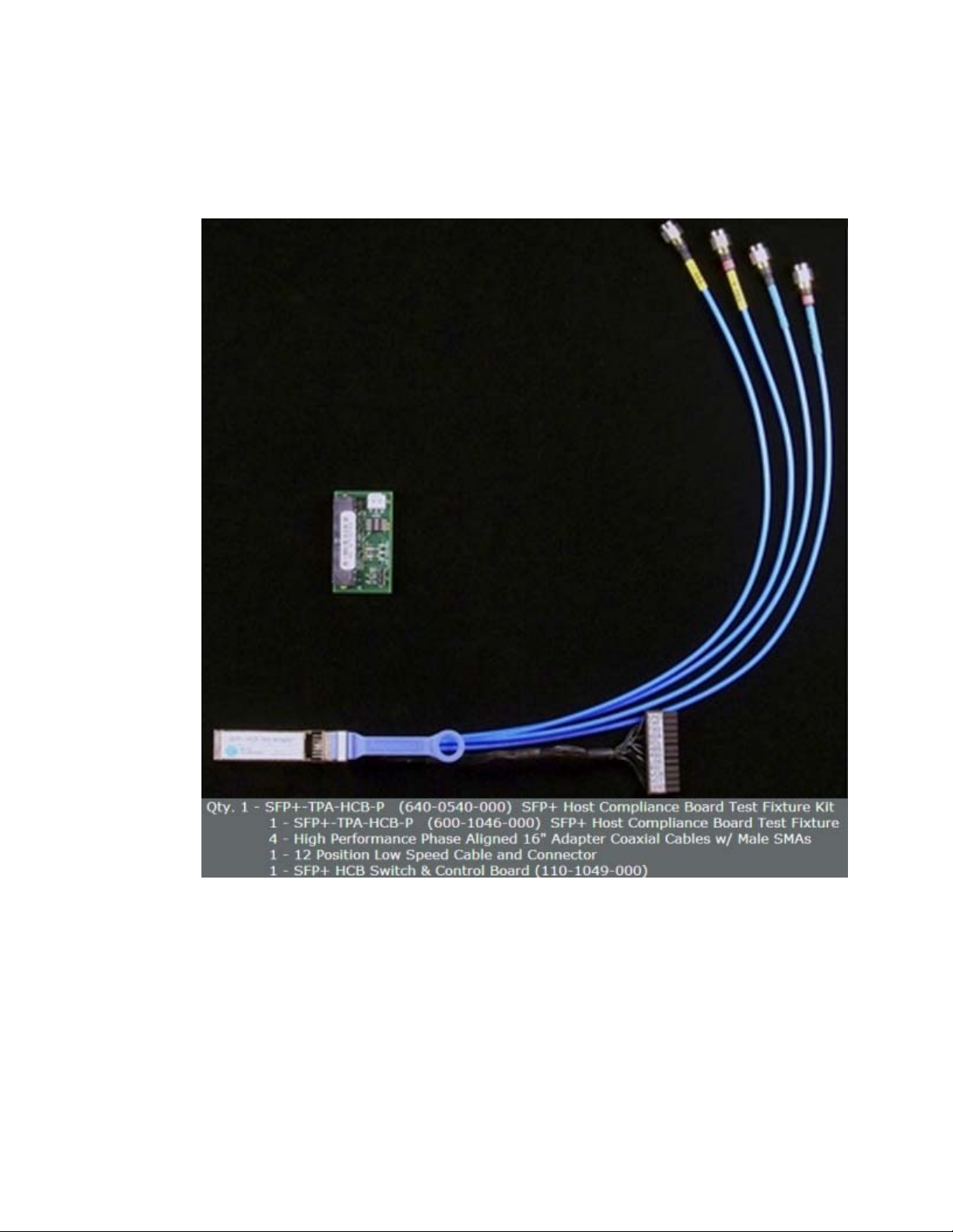
N6468A Host Compliance Board Test Fixture Kit
To use the N6468A SFP+ electrical performance validation and compliance
software, you need N6468A SFP+ Host Compliance Board Test Fixture Kit.
A test fixture is used to probe the signals to run the tests. You can
16 SFP+ Compliance Testing Methods of Implementation
Page 17
Preparing to Take Measurements 3
purchase this fixture kit online from
http://shop.wilder- tech.com/category_s/35.htm. Agilent recommends the
use of Wilder SFP+- TPA- HCB- P.
Figure 1 N6468A SFP+ Host Compliance Board Test Fixture Kit
Probing points on the main test fixture board allow most oscilloscope
measurements to be made using an Agilent Infiniium GUI for the
underlying scope. Some measurements are made using a BNC cable.
SFP+ Compliance Testing Methods of Implementation 17
Page 18
3 Preparing to Take Measurements
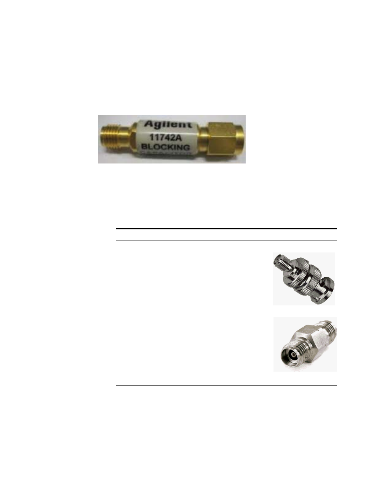
Blocking Capacitors
The host tests require the SFP+ host transmitter to be AC coupled to the
oscilloscope. A blocking capacitor is used to achieve this. Blocking
capacitors are coaxial components used to prevent the flow of DC
frequencies between the oscilloscope and DUT. An AC coupling with a 3
dB corner frequency of 20 kHz eliminates the baseline wander effects.
Figure 2 Blocking Capacitor
Converter
Converters are required for Infiniium oscilloscopes to connect the output
of the transmitter to the oscilloscope.
Tab le 2 Converter
Oscilloscope Converter Image
90000A BNC to SMA Converter
90000X/90000Q SMA to SMA Converter
18 SFP+ Compliance Testing Methods of Implementation
Page 19

Calibrating the Oscilloscope
NOTE
NOTE
If you haven’t already calibrated the oscilloscope, see Appendix 5,
“Calibrating the Infiniium Oscilloscope and Probe”.
If the ambient temperature changes more than 5 degrees Celsius from the
calibration temperature, internal calibration should be performed again.
The delta between the calibration temperature and the present operating
temperature is shown in the Utilities>Calibration menu.
If you switch cables or probes between channels or other oscilloscopes, it
is necessary to perform cable and probe calibration again. Agilent
recommends that, once calibration is performed, you label the cables with
the channel for which they were calibrated.
Preparing to Take Measurements 3
SFP+ Compliance Testing Methods of Implementation 19
Page 20

3 Preparing to Take Measurements
Setting Up DUT Connections
The SFP+ host transmitter is connected to the oscilloscope with two SMA
cables. The SFP+ host transmitter is to be AC coupled to the oscilloscope
for all measurements.
Connecting the Host Transmitter Board
You need to perform the following steps to connect the host compliance
board (HCB) to an oscilloscope:
1 Plug the SFP+ Host Compliance Board (HCB) into the SFP+ DUT.
2 Connect DC blocks to the Lane 1 TX+ and TX- output of the HCB.
3 Connect the Lane 1 TX+ output of the HCB to Channel 1 using an SMA
cable.
4 Configure the SFP+ host to transmit the required test pattern.
The following figure shows the connection diagram between the HCB and
an oscilloscope:
Figure 3 Host Transmitter Output Connection Diagram
20 SFP+ Compliance Testing Methods of Implementation
Page 21

Starting the SFP+ Compliance Test application
NOTE
1 From the Infiniium oscilloscope’s main menu, choose Analyze>Automated
Test Apps>N6468A SFP+ Test App.
Preparing to Take Measurements 3
Figure 4 N6468 SFP+ Test Application Option
If N6468A SFP+Test App does not appear in the Automated Test Apps
menu, the SFP+ Compliance Test application has not been installed.
For information on the procedure to install SFP+ Compliance Test
application see Chapter 2, “Installing the SFP+ Compliance Test
application”
SFP+ Compliance Testing Methods of Implementation 21
Page 22
3 Preparing to Take Measurements
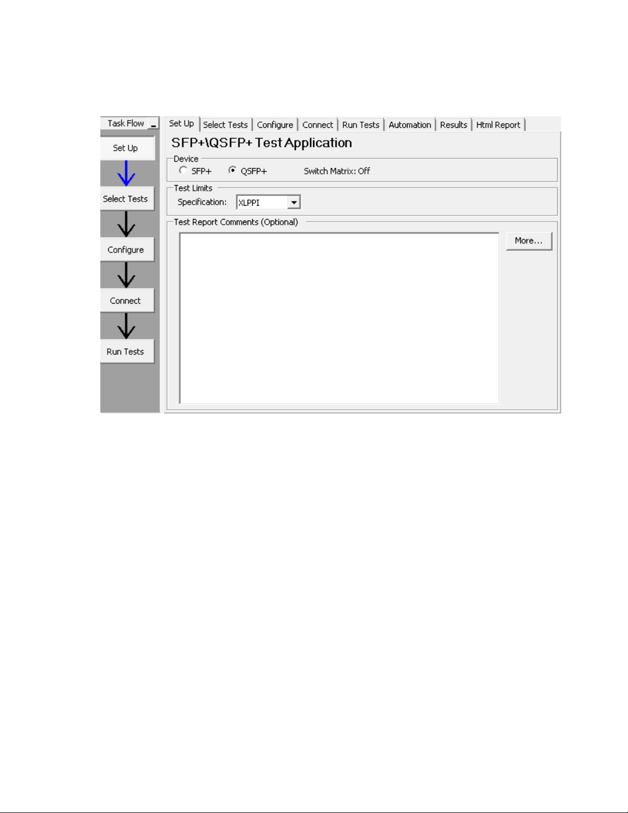
Figure 5 SFP+ Compliance Test Application
The above figure shows the SFP+ Compliance Test application main
window. The Ta s k F lo w navigation pane and the tabs in the main pane
show the steps required to configure and execute the automated tests:
li
Set Up Lets you select the Device as SFP+ or QSFP+ to
execute the tests. Lets you select the test category for
the desired host transmitter output test. Allows you
to select the setting for direct copper cable
attachment to check the compliance. Allows you to
document test report comments.
Select Tests Lets you select the tests you want to run. The tests
are organized hierarchically so you can select all tests
in a group. After tests are run, status indicators show
which tests have passed, failed, or not been run, and
there are indicators for the test groups.
Configure Lets you configure test parameters. The information
appears in the HTML report.
Connect Shows you how to connect the oscilloscope to the
device under test for the tests to be run.
22 SFP+ Compliance Testing Methods of Implementation
Page 23

Preparing to Take Measurements 3
Run Tests Starts the automated tests. If the connections to the
device under test need to be changed while multiple
tests are running, the tests pause, show you how to
change the connection, and wait for you to confirm
that the connections have been changed before
continuing.
Automation Lets you construct scripts of commands that drive
execution of the application.
Results Contains more detailed information about the tests
that have been run. You can change the thresholds at
which marginal or critical warnings appear.
HTML Report Shows a compliance test report that can be printed.
SFP+ Compliance Testing Methods of Implementation 23
Page 24

3 Preparing to Take Measurements
Online Help Topics
For information on using the SFP+ Compliance Test application, see its
online help (which you can access by choosing Help>Contents... from the
application’s main menu).
The SFP+ Compliance Test application’s online help describes the
following:
• SFP+ Compliance Test Application—At a Glance
• Starting the SFP+ Compliance Test Application
• To view/minimize the task flow pane
• To view/hide the toolbar
• Creating or Opening a Test Project
• To set load preferences
• Setting Up the Test Environment
• Enabling Switch Matrix
• Setting Up InfiniiSim
• Setting Up the Precision Probe/Cable
• Selecting Tests
• Configuring Tests
• Connecting the Oscilloscope to the DUT
24 SFP+ Compliance Testing Methods of Implementation
Page 25

Preparing to Take Measurements 3
• Running Tests
• To select the "store mode"
• To run multiple times
• To send emails on pauses or stops
• To pause or stop on events
• To specify the event
• To set the display preferences
• To set the run preferences
• Automating the Application
• Viewing Results
• To delete trials from the results
• To show reference images and flash mask hits
• To change margin thresholds
• To change the test display order
• To set trial display preferences
• To set HTML Report preferences
• Viewing/Exporting/Printing the Report
• To export the report
• To print the report
• Understanding the Report
• Saving Test Projects
• To set AutoRecovery preferences
• User- Defined Add- Ins
• To install an add- in
• To remove an add- in
• Controlling the Application via a Remote PC
• To check for the App Remote license
• To identify the remote interface version
• To enable the remote interface
• To enable remote interface hints
• Using a Second Monitor
SFP+ Compliance Testing Methods of Implementation 25
Page 26

3 Preparing to Take Measurements
26 SFP+ Compliance Testing Methods of Implementation
Page 27

N6468A SFP+ Compliance Test application
Methods of Implementation
4
Host Transmitter Output Electrical
Specifications Tests
SFP+ Host Transmitter Output Electrical Specifications at B 28
XLPPI Host Electrical Output Specification at TP1a 57
This chapter provides the Methods of Implementation (MOIs) for host
transmitter output electrical specifications tests using the SFP+
Compliance Test application. In this chapter, the host transmitter output
electrical specifications tests are categorized as:
• SFP+ Host Transmitter Output Electrical Specifications at B
• XLPPI Host Electrical Output Specification at TP1a
Agilent Technologies
27
Page 28

4 Host Transmitter Output Electrical Specifications Tests
SFP+ Host Transmitter Output Electrical Specifications at B
This section describes the Enhanced Small Form Factor Pluggable (SFP+)
electrical interface specifications tests for host transmitter output at B.
The SFP+ electrical interface specifications includes management,
mechanical, low speed signalling, high speed signalling, and appendices
providing parameter and test board definitions, and implementation and
measurement descriptions. The SFP+ electrical interface specifications are
compiled in SFF- 8431.
The SFP+ electrical interface specifications for host transmitter output at
B are categorized as:
• SFP+ SFI: The high speed serial electrical interface between the host
and the SFP+ module is called SFI. The SFP+ SFI electrical interface
specification determines the host compliance test points definition and
measurements and SFP+ host system specifications.
• 10GSFP+ Cu: The electrical interface used to implement the passive
direct attach SFP+ cable assemblies is called 10GSP+ Cu. This electrical
specification determines additional requirements or exceptions to
implement the SFP+ host system specifications.
The SFP+ electrical interface specifications for host transmitter output at
B define the measurement standards to execute various tests based on the
following tests pattern:
• Test pattern 8180
• Test pattern PRBS9
• Test pattern PRBS31
Test Pattern 8180
Test pattern 8180 represents a repeating square wave which consists of
eight continuous 1s followed by eight continuous 0s. This test pattern is
used to check the SFP+ compliance against SFF- 8431 specification for the
following tests:
• Signal Rise Time (20%- 80%)/Signal Fall Time (80%- 20%) Test
• Transmitter Qsq/Transmitter Qsq for Cu Test
• Voltage Modulation Amplitude VMA for Cu (VMA) (p- p) Test
Signal Rise Time (20%-80%)/Signal Fall Time (80%-20%) Test
The Signal Rise Time (20%-80%)/Signal Fall Time (80%-20%) test measures the
signal rise time and signal fall time of a SFP+ host transmitter
respectively. The purpose of this test is to verify that the signal rise time
or signal fall time of the SFP+ host transmitter is within the conformance
limits of 34 ps as per the specification.
28 SFP+ Compliance Testing Methods of Implementation
Page 29

Host Transmitter Output Electrical Specifications Tests 4
NOTE
NOTE
For information about the connection diagram, refer to “Connecting
the Host Transmitter Board" on page 20.
Configuring Test Parameter
To execute the Signal Rise Time (20%-80%)/Signal Fall Time (80%-20%) test, you
need to configure the #Averages(16) parameter. The #Averages(16)
parameter is used to reduce the effect of noise on the measurement. The
value of one average is calculated by averaging multiple acquisitions of the
waveform. Sixteen (16) is used as the default value but you can increase
or decrease this number to reduce or upsurge the effects of noise and
random signal variations.
Averaging can be used to reduce measurement noise and increase
measurement resolution; however, the specification does not provide
any constraints on how much averaging may be used but increase in
the value of the #Averages(16) parameter leads to diminishing results.
Understanding the Test Flow
The following references from the SFF- 8431 specification are considered to
check the compliance of the DUT:
[1] SFF- 8431, Appendix D.7
[2] SFF- 8431, Appendix D.6
[3] SFF- 8431, Section 3.5.1, Table 12
The SFP+ test application performs the following automated steps for
measuring the Signal Rise Time (20%-80%)/Signal Fall Time (80%-20%) test based
on the above mentioned references:
1 Triggers one cycle of the 8180 waveform on the rising edge.
2 Analyzes the signal rise/fall time of the signal at logic 0 and logic 1
voltage levels. The measurement procedure of the logic 0 and logic 1
state is defined as per reference [1]. The average voltage level in the
central 20% of each time interval is measured.
3 Measures the 20% to 80% signal rise time using the logic 0 voltage level
as base level and logic 1 voltage level as top level of the isolated edges
in case of the Signal Rise Time (20%-80%) test. Measures the 80% to 20%
fall time using the logic 1 voltage level as base level and logic 0 voltage
level as top level of the isolated edges in case of the Signal Fall Time
(80%-20%) test. From reference [2], the optical modulation amplitude
(OMA) test pattern (eight ones, eight zeros) is being used as the
normative test pattern. The 0% level and 100% level are the voltage
SFP+ Compliance Testing Methods of Implementation 29
Page 30
4 Host Transmitter Output Electrical Specifications Tests
levels of the logic 0 state and logic 1 state respectively as defined by
the xMA measurement procedure in the specification.
4 Analyzes the signal and verifies that this is as per the conformance
limits as specified in reference [3].
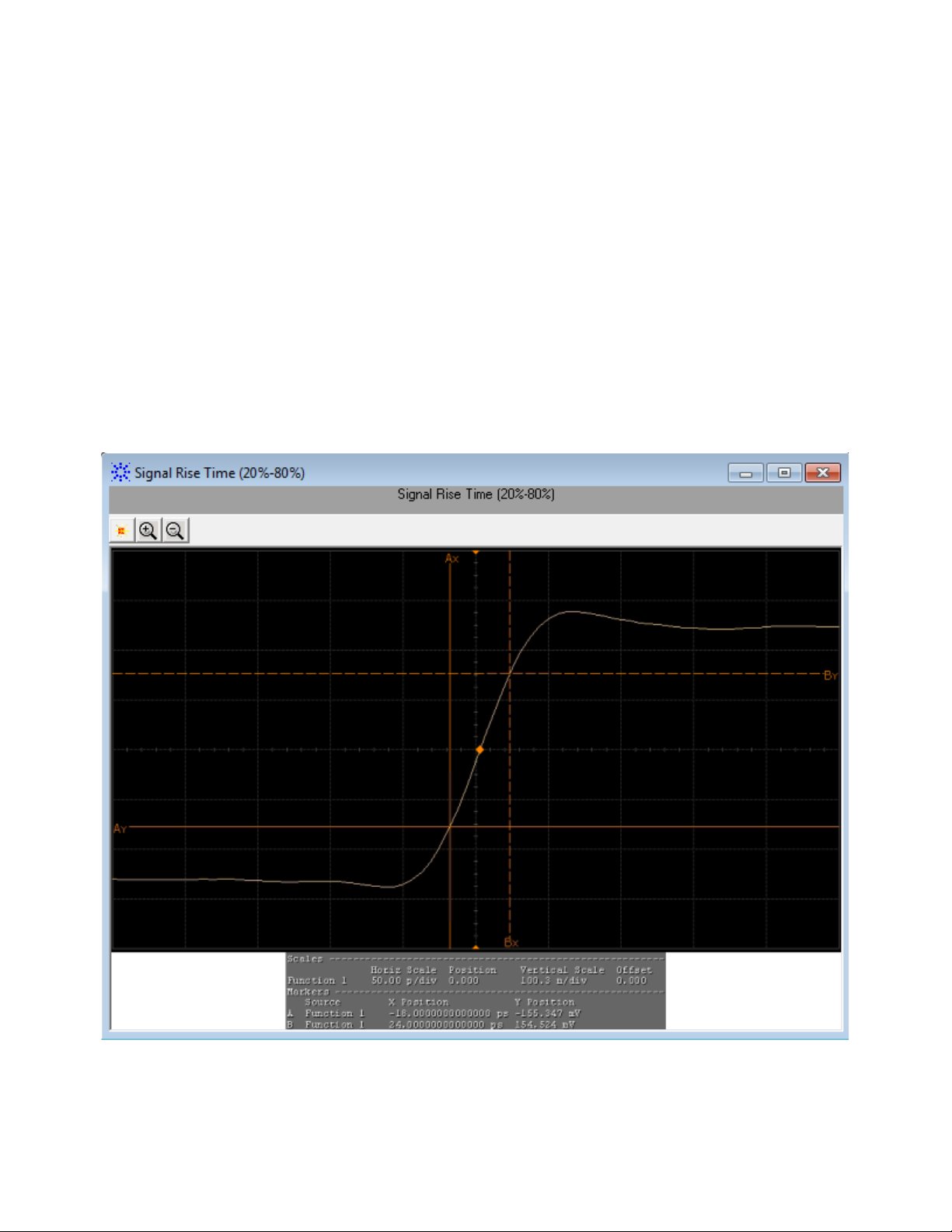
Viewing Test Results
For each test trial, its result is displayed on the Results tab. Click the
desired test to view its result. Details of the test results are described in
the lower pane. A sample reference image based on the measured values is
captured by the oscilloscope. You can click the sample reference image to
view the details. For information about the test results, refer to Viewing
Results in the online help.
Figure 1 Reference Image for Signal Rise Time (20%-80%) Test
30 SFP+ Compliance Testing Methods of Implementation
Page 31

Host Transmitter Output Electrical Specifications Tests 4
NOTE
Q
sq
1
SNR
---------- -
=
Q
sq
1
RN
------- -
VMA
2 noise RMS
---------------------------------------------
==
noise RMS
LogicONEnoise RMS
2
logicZEROnoise RMS
2
+
2
-----------------------------------------------------------------------------------------------------------------------------------=
Transmitter Qsq/Transmitter Qsq for Cu Test
The Transmitter Qsq/Transmitter Qsq for Cu test is a measure of reciprocal of
signal to noise ratio (SNR) of the SFP+ host transmitter.
As per SFF- 8431, Appendix D.8, Q
is given by 1/RN when the
sq
logicONEnoise (RMS) equals logicZEROnoise (RMS), whereby, RN refers to
relative noise and is calculated using the following formula:
To calculate RN,
• The value for voltage modulation amplitude (VMA) measurement is as
defined in SFF- 8431, Appendix D.7.
measurement of VMA, refer to
For information on the
“Voltage Modulation Amplitude for Cu
(VMA) (p- p) Test" on page 34.
• Noises at both logic levels are measured and the rms technique is
applied according to the following equation:
The purpose of this test is to verify that the signal to noise ratio of the
SFP+ host transmitter is within the conformance limits of 50.
SFP+ Compliance Testing Methods of Implementation 31
Configuring Test Parameter
To execute the Transmitter Qsq/Transmitter Qsq for Cu test, you need to
configure the #Waveforms(60) parameter. The #Waveforms(60) parameter is
used to reduce the effect of noise on the measurement. Sixty (60) is used
as the default value but you can increase or decrease this number to
reduce or upsurge the effects of noise and random signal variations.
For information about the connection diagram, refer to “Connecting
the Host Transmitter Board" on page 20.
Page 32

4 Host Transmitter Output Electrical Specifications Tests
Understanding the Test Flow
The following references from the SFF- 8431 specification are considered to
check the compliance of the DUT:
[1] SFF- 8431, Appendix D.7
[2] SFF- 8431, Appendix D.8
[3] SFF- 8431, Section 3.5.1, Table 12 (For
[4] SFF- 8431, Appendix E.2, Table 33 (For
The SFP+ test application performs the following automated steps for
executing the Transmitter Qsq/Transmitter Qsq for Cu test based on the above
mentioned references:
1 Triggers one cycle of the 8180 waveform on the rising edge.
2 Analyzes the rise/fall time of the signal at logic 0 and logic 1 voltage
levels. Reference [1] defines the measurement procedure of the logic 0
and logic 1 states. The average voltage level in the central 20% of each
time interval is measured.
3 Measures the value for VMA using the logic 0 voltage level as base level
and logic 1 voltage level. For information on the measurement of VMA,
refer to
page 34.
4 Measures the root mean square (RMS) noise for the logic 0 and logic 1
levels. From reference [2], the optical modulation amplitude (OMA) test
pattern (eight ones, eight zeros) is being used as the normative test
pattern. The 0% level and 100% level are the voltage levels of the logic 0
state and logic 1 state respectively as defined by the xMA measurement
procedure in the specification.
“Voltage Modulation Amplitude for Cu (VMA) (p- p) Test" on
Transmitter Qsq Test)
Transmitter Qsq for Cu Test)
5 Calculates the value of Q
6 Analyzes the signal and verify that this is as per the conformance limits
of 50 as specified in reference [3] for Tra nsm itt er Q s q test. Analyzes the
signal and verify that this is as per the conformance limits of 63.1 as
specified in reference [4] for Transmitter Qsq for Cu test.
using the formula mentioned above.
sq
Viewing Test Results
For each test trial, its result is displayed on the Results tab. Click the
desired test to view its result. Details of the test results are described in
the lower pane. A sample reference image based on the measured values is
captured by the oscilloscope. You can click the sample reference image to
view the details. For information about the test results, refer to Viewing
Results in the online help.
32 SFP+ Compliance Testing Methods of Implementation
Page 33
Host Transmitter Output Electrical Specifications Tests 4
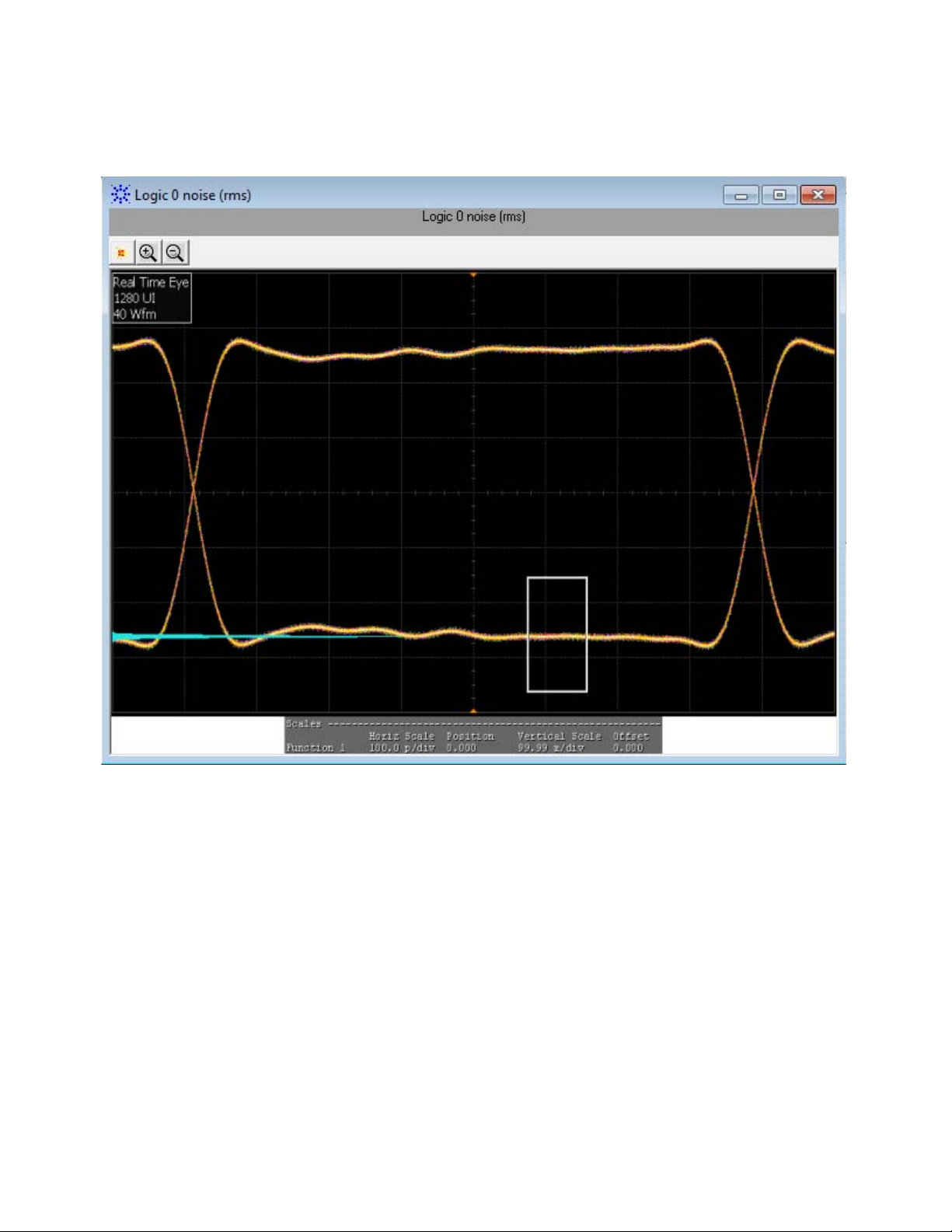
Figure 2 Reference Image for Transmitter Q
Tes t f or Log ic 0
sq
SFP+ Compliance Testing Methods of Implementation 33
Page 34
4 Host Transmitter Output Electrical Specifications Tests
NOTE
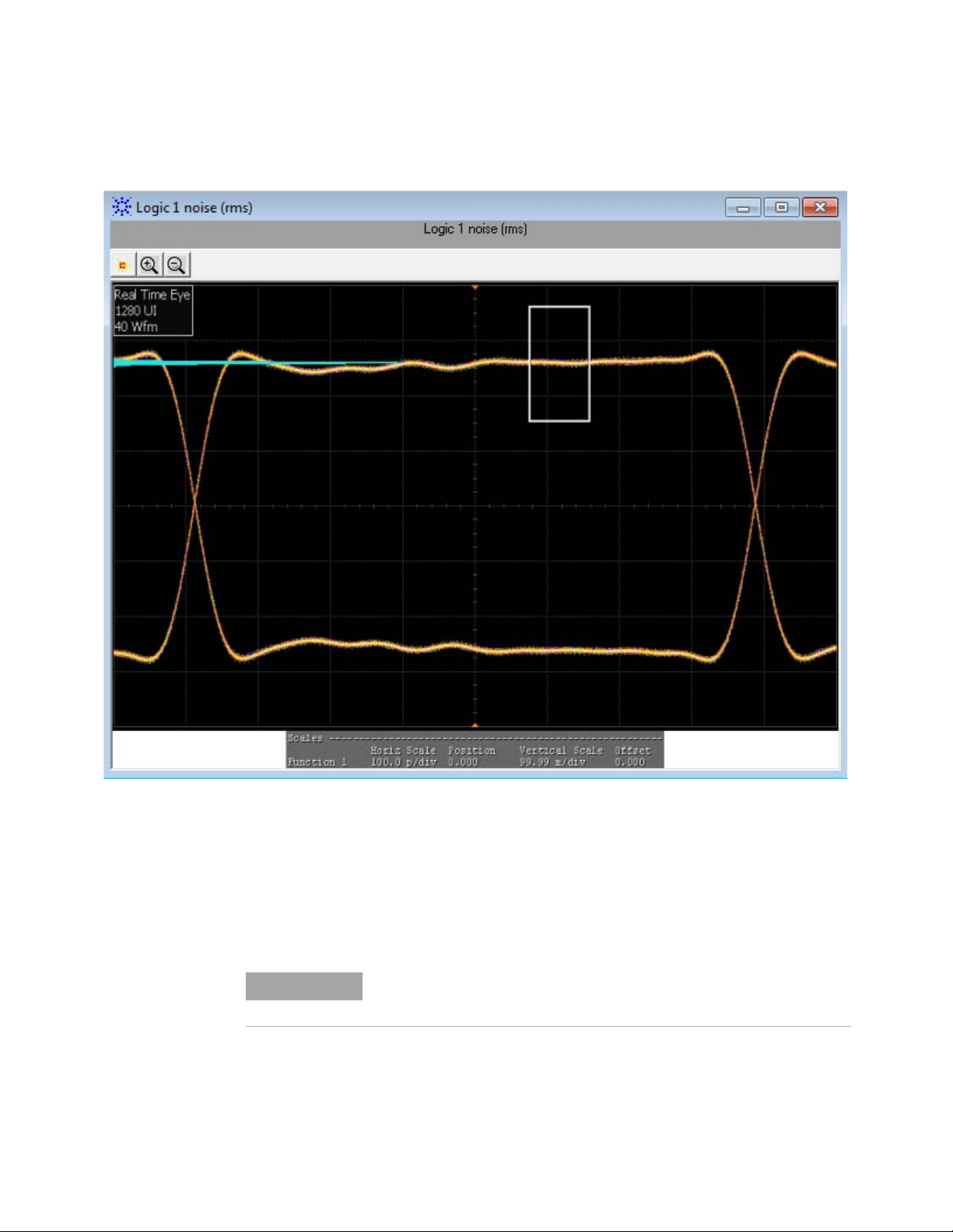
Figure 3 Reference Image for Transmitter Q
Voltage Modulation Amplitude for Cu (VMA) (p-p) Test
The Voltage Modulation Amplitude for Cu (VMA) (p-p) test measures the voltage
modulation amplitude (VMA) value from peak-to- peak (p- p) for a SFP+
host transmitter supporting passive direct attach cables.
For information about the connection diagram, refer to “Connecting
the Host Transmitter Board" on page 20.
Tes t f or Log ic 1
sq
34 SFP+ Compliance Testing Methods of Implementation
Page 35

Host Transmitter Output Electrical Specifications Tests 4
Understanding the Test Flow
The following references from the SFF- 8431 specification are considered to
check the compliance of the DUT:
[1] SFF- 8431, Appendix E.2, Table 33
[2] SFF- 8431, Appendix D.7
The SFP+ test application performs the following automated steps for
executing the Voltage Modulation Amplitude for Cu (VMA) (p-p) test based on the
above mentioned references:
1 Triggers one cycle of the 8180 waveform on the rising edge. One cycle
of the 8180 waveform is divided into two equally spaced time intervals
of 8 units interval long.
2 Measures the logic 0 voltage level as the average voltage level in the
central 20% of the negative pulse.
3 Measures the logic 1 voltage level as the average voltage level in the
central 20% of the positive pulse.
4 Measures the value for VMA as the difference between the logic 0
voltage level as base level and logic 1 voltage level as defined in
Reference [2]. Reference [1] specifies minimum value of VMA as 300
mV.
Viewing Test Results
For each test trial, its result is displayed on the Results tab. Click the
desired test to view its result. Details of the test results are described in
the lower pane. A sample reference image based on the measured values is
captured by the oscilloscope. You can click the sample reference image to
view the details. For information about the test results, refer to Viewing
Results in the online help.
SFP+ Compliance Testing Methods of Implementation 35
Page 36
4 Host Transmitter Output Electrical Specifications Tests
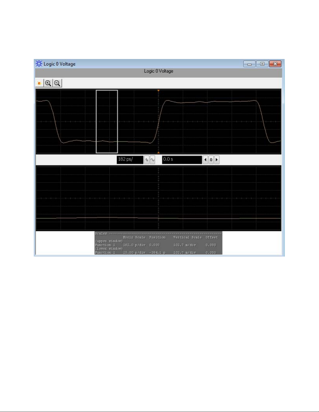
Figure 4 Reference Image for VMA for Cu (p-p) Test for Logic 0
36 SFP+ Compliance Testing Methods of Implementation
Page 37
Host Transmitter Output Electrical Specifications Tests 4
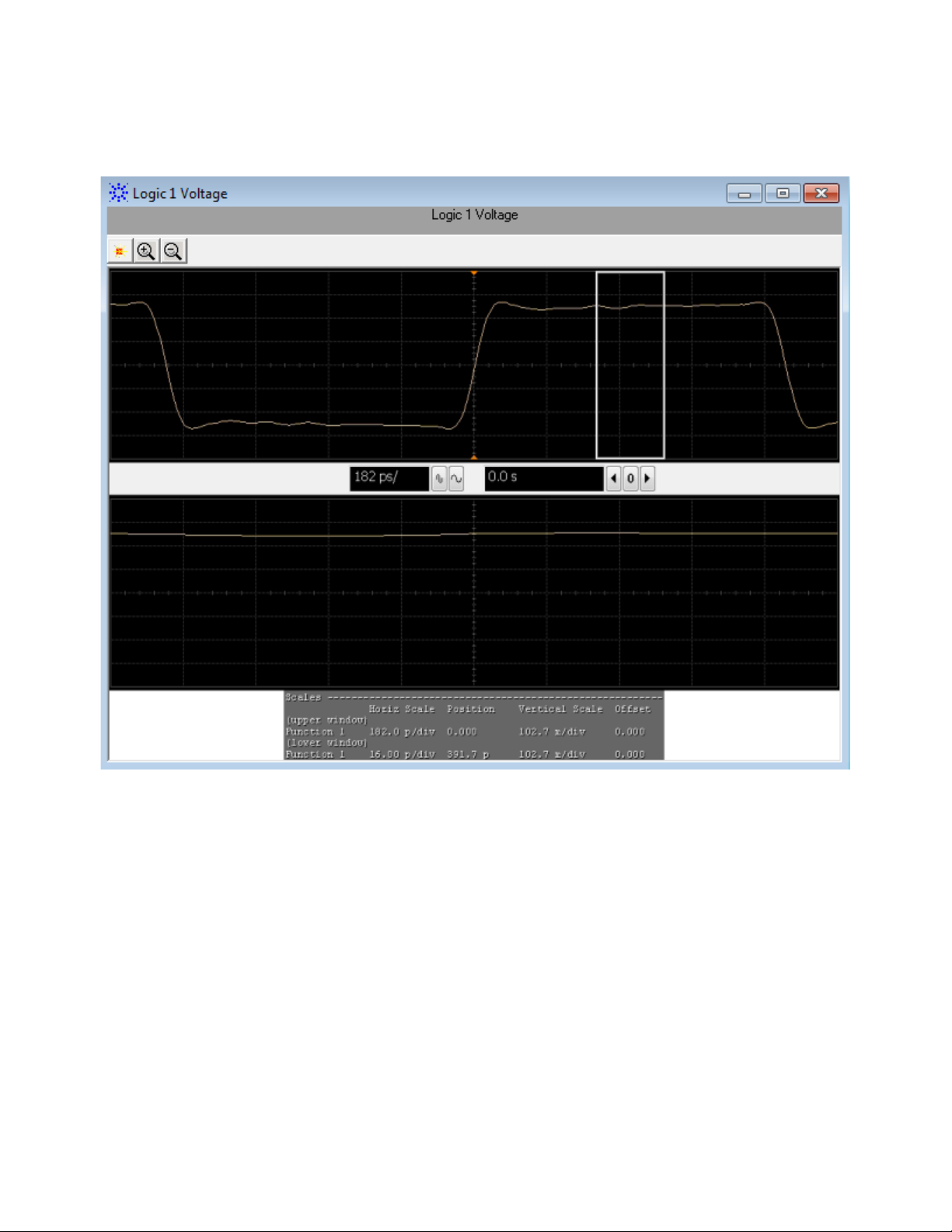
Figure 5 Reference Image for VMA for Cu (p-p) Test for Logic 1
Test Pattern PRBS9
PRBS9 test pattern represents a pseudorandom binary sequence with a
repetition period of 2
following tests:
• Data Dependent Jitter (DDJ) (p- p) Test
• Data Dependent Pulse Width Shrinkage (DDPWS) (p- p) Test
• Uncorrelated Jitter (UJ) (RMS) Test
• Transmitter Waveform Distortion Penalty for Cu (TWDPc) Test
9
- 1. This test pattern is used to measure jitter for the
SFP+ Compliance Testing Methods of Implementation 37
Page 38

4 Host Transmitter Output Electrical Specifications Tests
NOTE
DDJ max t1t2 tn,min t1t2 tn,–=
t
n
Data Dependent Jitter (DDJ) (p-p) Test
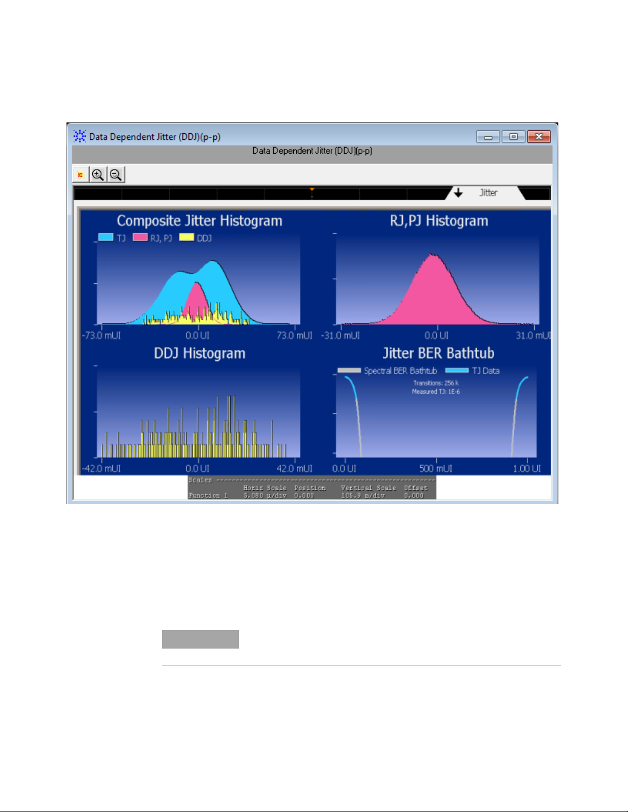
The Data Dependent Jitter (DDJ) (p-p) test measures the undesired deviation of
data at threshold- crossing time from true periodicity of an assumed
periodic signal in reference to a clock source. The purpose of this test is
to measure the deviation of data threshold- crossing time from
peak- to- peak (p- p) using the SFP+ host compliance application.
For information about the connection diagram, refer to “Connecting
the Host Transmitter Board" on page 20.
Understanding the Test Flow
The following references from the SFF- 8431 specification are considered to
check the compliance of the DUT:
[1] SFF- 8431, Appendix D.3
[2] SFF- 8431, Section 3.5.1, Table 12
The SFP+ test application performs the following automated steps for
executing the Data Dependent Jitter (DDJ) (p-p) test based on the above
mentioned references:
1 Triggers 1024 cycles of the PRBS9 waveform.
2 Turns on EZJIT complete and sets the pattern analysis mode to
periodic. As the PRBS9 pattern is relatively short, the DDJ pattern
completes in periodic pattern analysis mode.
3 Analyzes the signal and verifies that this is as per the conformance
limits of 100.0mUI as specified in reference [2]. DDJ is the jitter that is
correlated to its data pattern and is described by the formula:
whereby, is the difference between the expected time and actual time
of edge n.
Viewing Test Results
For each test trial, its result is displayed on the Results tab. Click the
desired test to view its result. Details of the test results are described in
the lower pane. A sample reference image based on the measured values is
captured by the oscilloscope. You can click the sample reference image to
view the details. For information about the test results, refer to Viewing
Results in the online help.
38 SFP+ Compliance Testing Methods of Implementation
Page 39
Host Transmitter Output Electrical Specifications Tests 4
NOTE
Figure 6 Reference Image for Data Dependent Jitter (DDJ) (p-p) Test
Data Dependent Pulse Width Shrinkage (DDPWS) (p-p) Test
The Data Dependent Pulse Width Shrinkage (DDPWS) (p-p) test measures the
value of data dependent pulse width shrinkage (DDPWS) from
peak- to- peak (p- p) of a SFP+ host transmitter.
For information about the connection diagram, refer to “Connecting
the Host Transmitter Board" on page 20.
SFP+ Compliance Testing Methods of Implementation 39
Page 40

4 Host Transmitter Output Electrical Specifications Tests
DDPWS T min t2t1– t3t2– t
n 1+tn
––=
Understanding the Test Flow
The following references from the SFF- 8431 specification are considered to
check the compliance of the DUT:
[1] SFF- 8431, Appendix D.3
[2] SFF- 8431, Section 3.5.1, Table 12
The SFP+ test application performs the following automated steps for
executing the Data Dependent Pulse Width Shrinkage (DDPWS) (p-p) test based
on the above mentioned references:
1 Triggers 1024 cycles of the PRBS9 waveform.
2 Turns on EZJIT complete and sets the pattern analysis mode to
periodic. As the PRBS9 pattern is relatively short, the DDPWS pattern
completes in periodic pattern analysis mode.
3 Analyzes the signal and verifies that this is as per the conformance
limits of 100.0mUI as specified in reference [2]. For a capture with n
edges, DDPWS is measured as the difference between one symbol period
and the minimum pulse width of the entire capture. It is given by the
algorithm:
whereby, T is the symbol period of the data stream and tn is the time
of occurrence of edge n.
Viewing Test Results
For each test trial, its result is displayed on the Results tab. Click the
desired test to view its result. Details of the test results are described in
the lower pane. A sample reference image based on the measured values is
captured by the oscilloscope. You can click the sample reference image to
view the details. For information about the test results, refer to Viewing
Results in the online help.
40 SFP+ Compliance Testing Methods of Implementation
Page 41

Host Transmitter Output Electrical Specifications Tests 4
NOTE
Figure 7 Reference Image for Data Dependent Pulse Width Shrinkage (p-p) Test
Uncorrelated Jitter (UJ) (RMS) Test
The Uncorrelated Jitter (UJ) (RMS) test measures any jitter that is
un- correlated to the 64B/66B bit stream of a SFP+ host transmitter. The
measured jitter value is not related to the data pattern. For information
about the definition and considerations for UJ, refer to IEEE 802.3
CL68.6.8 and SFF- 8431, Appendix D.7.
For information about the connection diagram, refer to “Connecting
the Host Transmitter Board" on page 20.
SFP+ Compliance Testing Methods of Implementation 41
Page 42

4 Host Transmitter Output Electrical Specifications Tests
Uncorrelated Jitter (rms)
r
2
f
2
+2=
rf
Configuring Test Parameter
To execute the UJ test, you need to configure the #Hits(100) parameter.
The #Hits(100) parameter is used as the default value but you can increase
or decrease this number to specify the minimum number of hits on the
histogram acquired for the Uncorrelated Jitter (UJ) (RMS) test.
Understanding the Test Flow
The following references from the SFF- 8431 and IEEE 802.3 specifications
are considered to check the compliance of the DUT:
[1] SFF- 8431, Section 3.5.1, Table 12
[2] IEEE 802.3, Section 68.6.8
The SFP+ test application performs the following automated steps for
executing the Uncorrelated Jitter (UJ) (RMS) test based on the above
mentioned references:
1 Triggers and persists multiple cycles of the PRBS9 waveform on the
scope.
2 Places a histogram on the average power level of the rising edge and
falling edge.
3 Measures the standard deviation, , of the rising and falling edge.
4 Calculates the RMS value of the UJ using the formula as specified in
reference [2] and is given by:
Where, is the standard deviation of the rising edge
is the standard deviation of the falling edge
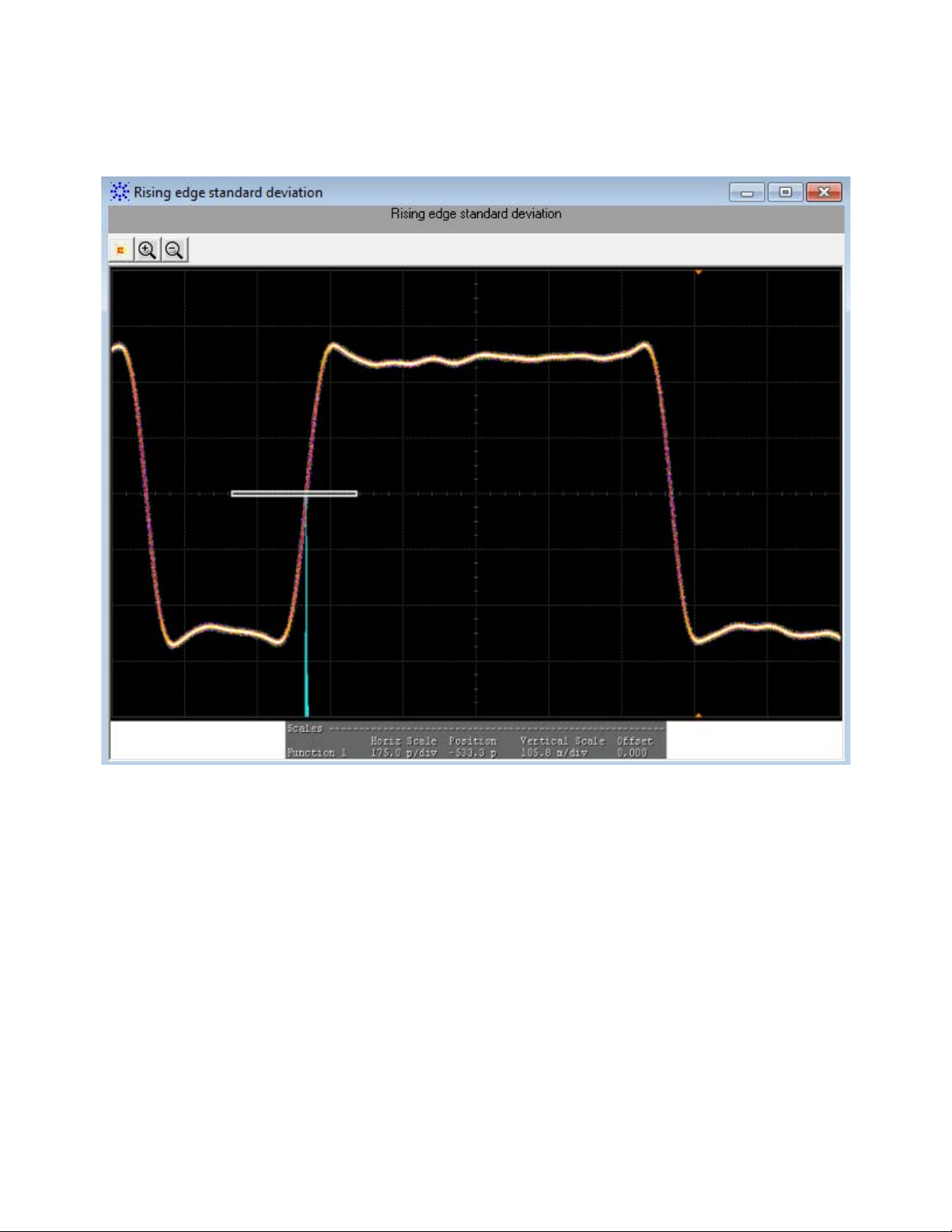
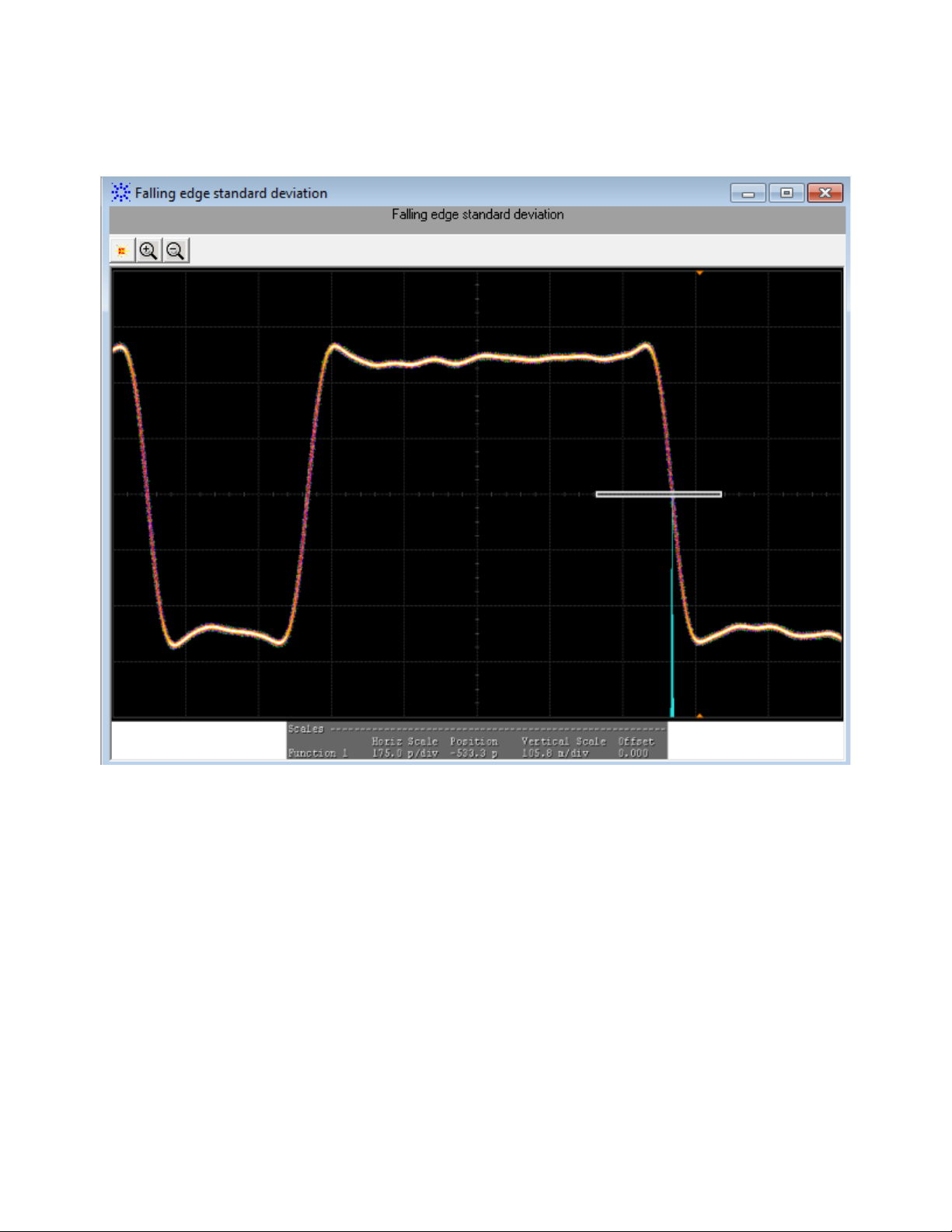
The standard deviation of the rising and falling edge is measured using
a histogram window that is positioned at the average power level of the
signal.
Viewing Test Results
For each test trial, its result is displayed on the Results tab. Click the
desired test to view its result. Details of the test results are described in
the lower pane. A sample reference image based on the measured values is
captured by the oscilloscope. You can click the sample reference image to
view the details. For information about the test results, refer to Viewing
Results in the online help.
42 SFP+ Compliance Testing Methods of Implementation
Page 43
Host Transmitter Output Electrical Specifications Tests 4
Figure 8 Reference Image for Uncorrelated Jitter (RMS) Test for Rising Edge
SFP+ Compliance Testing Methods of Implementation 43
Page 44
4 Host Transmitter Output Electrical Specifications Tests
Figure 9 Reference Image for Uncorrelated Jitter (RMS) Test for Falling Edge
Transmitter Waveform Dispersion Penalty for Cu (TWDPc) Test
The transmitter waveform dispersion penalty for Cu (TWDPc) test measures the
transmitter waveform dispersion penalty of a SFP+ host transmitter
supporting passive direct attach cables. Waveform distortion penalty
(WDP) is a measure of dispersion penalty due to a particular transmitter
with reference to emulated transmission lines and receiver.
The WDP algorithm expects 16 samples per UI. For a 10GBase- T signal,
this would require a sampling rate of around 160GSa/s. This sampling rate
is not possible for most of the scopes, so interpolation is enabled during
acquisition to achieve the required number of samples. Sin (x)/x is one of
the methods recommended in SFF- 8431, Appendix D.9 and this is also the
same interpolation method used by Infiniium.
44 SFP+ Compliance Testing Methods of Implementation
Page 45

Host Transmitter Output Electrical Specifications Tests 4
NOTE
NOTE
NOTE
The interpolated data pattern will need to be further processed as the
algorithm required does not have exactly 16 samples per unit interval.
Re- sampling is done by performing a simple interpolation, followed by
decimation to achieve the exact number of samples.
For information about the connection diagram, refer to “Connecting
the Host Transmitter Board" on page 20.
Understanding the Test Flow
The following references from the SFF- 8431 and IEEE 802.3 specifications
are considered to check the compliance of the DUT:
[1] SFF- 8431, Appendix E.2, Table 33
[2] SFF- 8431, Appendix G
[3] SFF- 8431, Appendix D.9
[4] IEEE 802.3, Section 68.6.6.1
The SFP+ test application performs the following automated steps for
executing the Transmitter waveform dispersion penalty for Cu (TWDPc) test:
1 Triggers one cycle of the PRBS9 waveform with averaging and sin (x)/x
interpolation enabled.
2 Saves the waveform.
3 Processes the saved waveform as specified in “Compiling the Matlab
Deployment Project" on page 45. For a compliant SFP+ host transmitter,
reference [1] specifies a maximum TWDPc of 10.7dBe.
Averaging is applied in order to reduce uncorrelated jitter and noise
effects as recommended in reference [3].
Compiling the Matlab Deployment Project
You need to perform the following steps to compile the Matlab script:
1 Launch MATLAB.
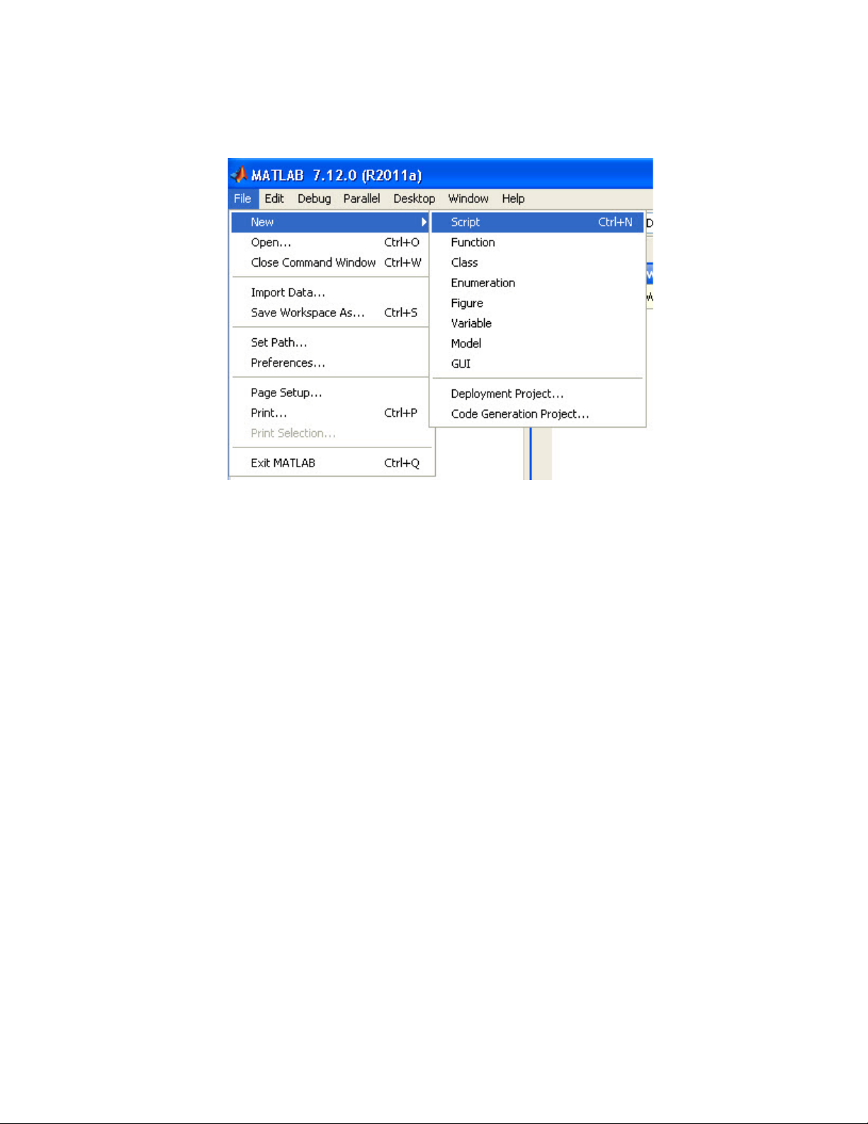
2 From the File menu, select New and click Script to create a matlab “.m”
file using the script provided in Appendix G of the SFF- 8431
specification.
Matlab 2011a(32-bit) is required to compile the script.
SFP+ Compliance Testing Methods of Implementation 45
Page 46
4 Host Transmitter Output Electrical Specifications Tests
3 From the File menu, select New and click Script to create another matlab
“.m” file using the following code:
function
SFF8431xWDPWrapper(WaveformFile,TxDataFile,EqNf,EqNb,SymbolRate,
Usage)
% wrapper for the SFF-8431 code
% convert input
EqNf = str2double(EqNf);
EqNb = str2double(EqNb);
SymbolRate = str2double(SymbolRate);
% copy the PRBS9 file into the working folder
XmitData = load(TxDataFile); %#ok<NASGU>
save('prbs9_950.txt','-ascii','XmitData');
[xWDP,MeasuredxMA]=SFF8431xWDP(WaveformFile,EqNf,EqNb,SymbolRate
,Usage);
% display the results. this will be captured on stdout. app will
parse
% stdout for the results. Do not change this order!
disp(xWDP);
disp(',');
disp(MeasuredxMA);
end
46 SFP+ Compliance Testing Methods of Implementation
Page 47

Host Transmitter Output Electrical Specifications Tests 4
4 From the File menu, select New and click Deployment Project to create a
new Matlab deployment project.
Figure 10 New Deployment Project
The Deployment Project dialog box appears.
5 Enter a name of the deployment project.
6 Specify a location to save the project.
7 Select Console Application in the Type drop- down list, and click OK.
Figure 11 The Deployment Project Dialog Box
The Console Application dialog box appears.
SFP+ Compliance Testing Methods of Implementation 47
Page 48

4 Host Transmitter Output Electrical Specifications Tests
8 Add the file created in step 2 into the Main File section.
9 Add the file created in step 1 into the Shared Resources and Helper Files
section.
Figure 12 The Console Application Dialog Box
10 Click to build the project and save the output file at the following
location:
“C:\Program Files (x86)\Agilent\Infiniium\Apps\SFP+Test\app\
matlab”
Viewing Test Results
For each test trial, its result is displayed on the Results tab. Click the
desired test to view its result. Details of the test results are described in
the lower pane. For information about the test results, refer to Viewing
Results in the online help.
Test Pattern PRBS31
PRBS31 test pattern represents a pseudorandom binary sequence with a
repetition period of 2
49.2.8. This test pattern is used to check the compliance of the SFP+ host
transmitter output using the following tests:
• Output AC Common Mode Voltage (rms) Test/Output AC Common Mode
Voltage for Cu (rms) Test
31
- 1. The sequence is defined in IEEE Std 802.3,
• Single Ended Voltage Range (Positive) Test/Single Ended Voltage Range
(Negative) Test
48 SFP+ Compliance Testing Methods of Implementation
Page 49

Host Transmitter Output Electrical Specifications Tests 4
NOTE
• Total Jitter (TJ) (p- p) Test
• Eye Mask Hit Ratio Test
Output AC Common Mode Voltage (rms) Test/Output AC Common Mode Voltage for Cu (rms) Test
The Output AC Common Mode Voltage (rms)/Output AC Common Mode Voltage for Cu
(rms) test measures the output AC common mode voltage of a SFP+ host
transmitter without/with passive direct attach cables attached respectively.
For information about the connection diagram, refer to “Connecting
the Host Transmitter Board" on page 20.
Understanding the Test Flow
The following references from the SFF- 8431 specification are considered to
check the compliance of the DUT:
[1] SFF- 8431, Appendix 3.5.1, Table 1 for Output AC Common Mode Voltage
(rms) test
[2] SFF- 8431, Appendix E.2, Table 33 for Output AC Common Mode Voltage
(rms) for Cu test
[3] SFF- 8431, Appendix D.15
The SFP+ test application performs the following automated steps for
executing the Output AC Common Mode Voltage (rms)/Output AC Common Mode
Voltage for Cu (rms) test:
1 Triggers the PRBS31 waveform.
2 Folds the PRBS31 waveform.
3 Places a histogram with a width of 1 unit interval across the folded
waveform. According to the procedure specified in reference [2], the
output AC common mode voltage (rms) is measured by applying a
histogram over one UI of the common mode signal. Multiple unit
intervals are overlapped to get an averaged measurement. The scope is
set to free run triggering as the oscilloscopes do not have the memory
depth for 1 cycle of the PRBS31 waveform. For a compliant SFP+ host
transmitter, reference [1] specifies a maximum AC common mode
voltage of 15mV, rms for Output AC Common Mode Voltage (rms) test. For a
compliant SFP+ host transmitter, reference [2] specifies a maximum AC
common mode voltage of 12mV, rms for Output AC Common Mode Voltage
(rms) for Cu test.
Viewing Test Results
SFP+ Compliance Testing Methods of Implementation 49
Page 50
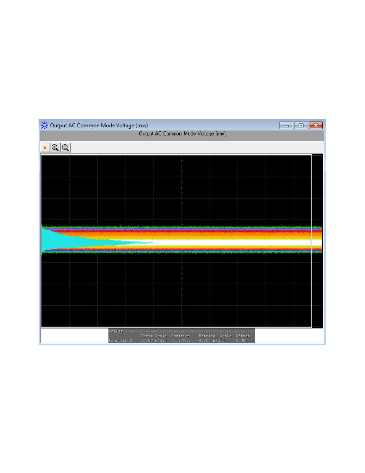
4 Host Transmitter Output Electrical Specifications Tests
For each test trial, its result is displayed on the Results tab. Click the
desired test to view its result. Details of the test results are described in
the lower pane. A sample reference image based on the measured values is
captured by the oscilloscope. You can click the sample reference image to
view the details. For information about the test results, refer to Viewing
Results in the online help
.
Figure 13 Reference Image for Output AC Common Mode Voltage (RMS) Test
Single Ended Voltage Range (Positive) Test/Single Ended Voltage Range (Negative) Test
The Single Ended Voltage Range (Positive) test/Single Ended Voltage Range (Negative)
test measures the voltage range of the positive (TX+) and negative (TX-)
signals respectively of a SFP+ host transmitter.
50 SFP+ Compliance Testing Methods of Implementation
Page 51

Host Transmitter Output Electrical Specifications Tests 4
NOTE
For information about the connection diagram, refer to “Connecting
the Host Transmitter Board" on page 20.
Understanding the Test Flow
The following reference from the SFF- 8431 specification is considered to
check the compliance of the DUT:
[1] SFF- 8431, Section 3.5.1, Table 11
The SFP+ test application performs the following automated steps for
executing the Single Ended Voltage Range (Positive) test/Single Ended Voltage Range
(Negative) test based on the above mentioned references:
1 Triggers the PRBS31 waveform.
2 Measures the peak- to- peak (p- p) voltage. For a compliant SFP+ host
transmitter, reference [1] specifies the single ended voltage range to be
between - 0.3V and 4.0V.
Viewing Test Results
For each test trial, its result is displayed on the Results tab. Click the
desired test to view its result. Details of the test results are described in
the lower pane. A sample reference image based on the measured values is
captured by the oscilloscope. You can click the sample reference image to
view the details. For information about the test results, refer to Viewing
Results in the online help.
SFP+ Compliance Testing Methods of Implementation 51
Page 52
4 Host Transmitter Output Electrical Specifications Tests
NOTE
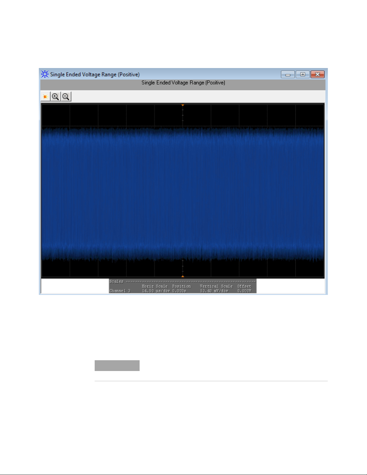
Figure 14 Reference Image for Single Ended Voltage Range (Positive) Test
Total Jitter (TJ) (p-p) Test
The Total Jitter (TJ) (p-p) test measures the total jitter of a SFP+ host
transmitter.
For information about the connection diagram, refer to “Connecting
the Host Transmitter Board" on page 20.
Understanding the Test Flow
The following references from the SFF- 8431 specification are considered to
check the compliance of the DUT:
[1] SFF- 8431, Section 3.5.1, Table 12
52 SFP+ Compliance Testing Methods of Implementation
Page 53

Host Transmitter Output Electrical Specifications Tests 4
NOTE
[2] SFF- 8431, Section 3.5.2, Appendix D.2
The SFP+ test application performs the following automated steps for
executing the Total Jitter (TJ) (p-p) test based on the above mentioned
references:
1 Triggers the PRBS31 waveform.
2 Turns on EZJIT Complete, and set the pattern analysis mode to Arbitrary
as the signal is relatively long.
3 Obtains the results for TJ for a compliant SFP+ host transmitter.
Reference [1] specifies a maximum TJ of 0.28UI, peak- to- peak.
The clock recovery method used is the one recommended in reference
[2], which is a second order PLL with a loop bandwidth of 4MHz and a
slope of -20dB/decade with a peaking of 0.1dB.
Viewing Test Results
For each test trial, its result is displayed on the Results tab. Click the
desired test to view its result. Details of the test results are described in
the lower pane. A sample reference image based on the measured values is
captured by the oscilloscope. You can click the sample reference image to
view the details. For information about the test results, refer to Viewing
Results in the online help.
SFP+ Compliance Testing Methods of Implementation 53
Page 54
4 Host Transmitter Output Electrical Specifications Tests
NOTE
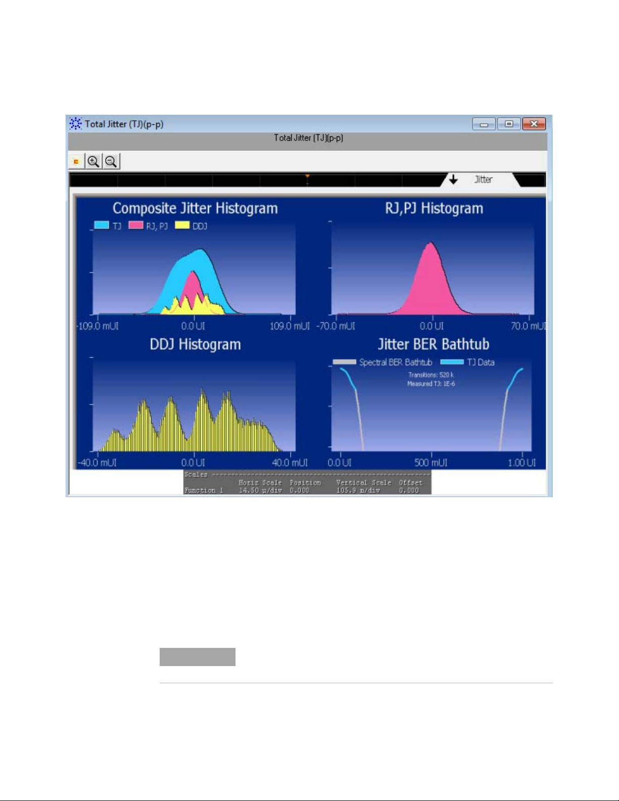
Figure 15 Reference Image for Total Jitter (TJ) (p-p) Test
Eye Mask Hit Ratio Test
The Eye Mask Hit Ratio test measures the eye mask hit ratio of SFP+ host
transmitter. The eye mask is defined by the parameters X1, X2, Y1, and
Y2. The eye is defined as measured using a receiver with an electrical
- 3dB bandwidth of 12GHz such as Bessel- Thomson response. As per the
relevant standard, the mask hit ratio is set to 5*10
For information about the connection diagram, refer to “Connecting
the Host Transmitter Board" on page 20.
-5
.
54 SFP+ Compliance Testing Methods of Implementation
Page 55

Host Transmitter Output Electrical Specifications Tests 4
NOTE
Hit Ratio
Total Mask Violations
Total Number of Samples in 1UI
-------------------------------------------------------------------=
Total Number of Samples in 1 UI Sampling Rate 1UI=
Understanding the Test Flow
The following references from the SFF- 8431 specification are considered to
check the compliance of the DUT:
[1] SFF- 8431, Section 3.5.1, Table 12
[2] SFF- 8431, Section 3.5.1, Appendix D.2
The SFP+ test application performs the following automated steps for
executing the Eye Mask Hit Ratio test:
Enables the Mask Test and loads the test. Enabling the Mask Test allows you
to conform the waveform as per the industry standards.
4 Triggers the PRBS31 waveform for the Mask Test.
5 Calculates the eye mask hit ratio. For a compliant SFP+ host
transmitter, reference [1] specifies an eye mask hit ratio that is less
than 5x10
The eye mask hit ratio is calculated using the formula:
-15
.
And the total number of samples in 1UI is given by:
The clock recovery method used is the one recommended in reference
[2], which is a second order PLL with a loop bandwidth of 4MHz and a
slope of -20dB/decade with a peaking of 0.1dB.
Viewing Test Results
For each test trial, its result is displayed on the Results tab. Click the
desired test to view its result. Details of the test results are described in
the lower pane. A sample reference image based on the measured values is
captured by the oscilloscope. You can click the sample reference image to
view the details. For information about the test results, refer to Viewing
Results in the online help.
SFP+ Compliance Testing Methods of Implementation 55
Page 56
4 Host Transmitter Output Electrical Specifications Tests
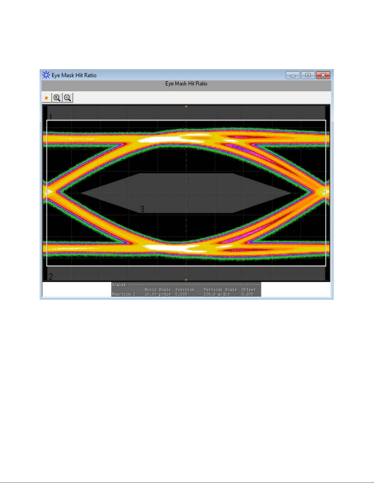
Figure 16 Reference Image for Eye Mask Hit Ratio Test
56 SFP+ Compliance Testing Methods of Implementation
Page 57

Host Transmitter Output Electrical Specifications Tests 4
NOTE
XLPPI Host Electrical Output Specification at TP1a
XLPPI host electrical output specification at TP1a describes the 40Gb/s
parallel physical interface (XLPPI, four lanes) used with 40GBASE- SR4 or
40GBASE- LR4 as an optional instantiation of the physical medium
dependent (PMD) service interface. The PMD service interface supports the
exchange of encoded data between the physical medium attachment (PMA)
entity and PMD entity. The PMD translates the encoded data to and from
signals suitable for the specified medium. The XLPPI electrical interface
specifications are compiled in IEEE 802.3.
The XLPPI electrical interface specifications for host transmitter output at
TP1a defines the measurement standards to execute various tests based on
the following tests pattern:
• Test pattern 8180
• Test pattern PRBS9
• Test pattern PRBS31
Before executing the tests based on the above mentioned test patterns, you
may need to calibrate the input signals to control the crosstalk effects at
the source.
Crosstalk Source Calibration
Crosstalk source calibration when applied to all the input lanes of the
XLPPI host allows the SFP+ test application to verify that the test results
at the output lane and signals are as per the conformance limits in the
specification. You may need to do the crosstalk source calibration for the
input signals based on the following crosstalk source signals:
• Crosstalk Source VMA (p- p) Calibration
• Crosstalk Source Rise Time (20%- 80%) Calibration
• Crosstalk Source Fall Time (80%- 20%) Calibration
The following section describes the execution of the above mentioned
crosstalk source signals by the SFP+ application.
Crosstalk Source VMA (p-p) Calibration
The Crosstalk Source VMA (p-p) calibration measures the voltage modulation
amplitude (VMA) for the crosstalk source calibration process.
For information about the connection diagram, refer to “Connecting
the Host Transmitter Board" on page 20.
SFP+ Compliance Testing Methods of Implementation 57
Page 58

4 Host Transmitter Output Electrical Specifications Tests
Understanding the Calibration Flow
The following reference from the IEEE802.3 specification is considered for
the crosstalk source VMA (p- p) calibration process:
[1] IEEE802.3ba- 2010, Annex 86A, Table 86A- 1
The SFP+ test application performs the following automated steps for
executing the Crosstalk Source VMA (p-p) calibration:
1 Triggers one cycle of the 8180 waveform on the rising edge. One cycle
of the 8180 waveform is divided into two equally spaced time intervals
of 8 units interval long.
2 Measures the logic 0 voltage level as the average voltage level in the
central 20% of the negative pulse.
3 Measures the logic 1 voltage level as the average voltage level in the
central 20% of the positive pulse.
4 Measures the value for VMA as the difference between the logic 0
voltage level as base level and logic 1 voltage level as defined in
Reference [2]. Reference [1] specifies minimum value of VMA as 300
mV.
Viewing Crosstalk Source Calibration Result
For each test trial, its result is displayed on the Results tab. Click the
desired test to view its result. Details of the test results are described in
the lower pane. A sample reference image based on the measured values is
58 SFP+ Compliance Testing Methods of Implementation
Page 59

Host Transmitter Output Electrical Specifications Tests 4
captured by the oscilloscope. You can click the sample reference image to
view the details. For information about the test results, refer to Viewing
Results in the online help.
Figure 17 Reference Image for Crosstalk Source VMA (p-p) for Logic 0
SFP+ Compliance Testing Methods of Implementation 59
Page 60
4 Host Transmitter Output Electrical Specifications Tests
NOTE
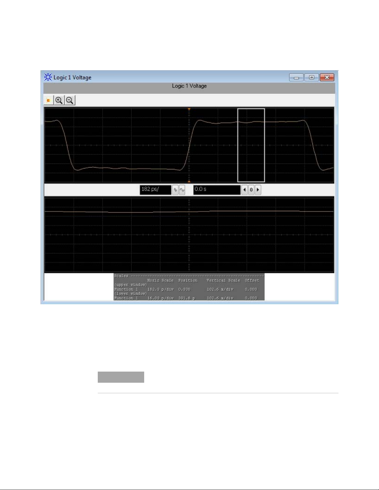
Figure 18 Reference Image for Crosstalk Source VMA (p-p) for Logic 1
Crosstalk Source Rise Time (20% - 80%) Calibration
The Crosstalk Source Rise Time calibration measures the 20%- 80% rise time for
the crosstalk source calibration process.
For information about the connection diagram, refer to “Connecting
the Host Transmitter Board" on page 20.
Understanding the Calibration Flow
The following references from the IEEE802.3 specification are considered
for the crosstalk source calibration process:
[1] IEEE802.3ba- 2010, Annex 86A, Table 86A- 1
60 SFP+ Compliance Testing Methods of Implementation
Page 61

Host Transmitter Output Electrical Specifications Tests 4
[2] IEEE802.3ba- 2010, Section 86A.5.3.3
[3] IEEE802.3, Section 68.6.2
The SFP+ test application performs the following automated steps for
executing the Crosstalk Source Rise Time (20%-80%) calibration:
1 Triggers one cycle of the 8180 waveform on the rising edge.
2 Measures the logic 0 and logic 1 voltage levels. The measurement
procedure of the logic 0 and logic 1 state is defined as per reference
[3]. The average voltage level in the central 20% of each time interval is
measured.
3 Measures the 20% to 80% rise time using the logic 0 voltage level as
base level and logic 1 voltage level as top level of the isolated edges.
From reference [2], the optical modulation amplitude (OMA) test
pattern (eight ones, eight zeros) is being used as the normative test
pattern. The 0% level and 100% level are the voltage levels of the logic 0
state and logic 1 state respectively as defined by the xMA measurement
procedure in the specification.
4 Analyzes the signal and verifies that this is as per the conformance
limits as specified in reference [1].
Viewing Crosstalk Result
For each test trial, its result is displayed on the Results tab. Click the
desired test to view its result. Details of the test results are described in
the lower pane. A sample reference image based on the measured values is
captured by the oscilloscope. You can click the sample reference image to
view the details. For information about the test results, refer to Viewing
Results in the online help.
SFP+ Compliance Testing Methods of Implementation 61
Page 62

4 Host Transmitter Output Electrical Specifications Tests
NOTE
Figure 19 Reference Image for Crosstalk Source Rise Time (20%-80%)
Crosstalk Source Fall Time (80% - 20%) Calibration
The Crosstalk Source Fall Time calibration measures the (80%- 20%) fall time
for the crosstalk source calibration process.
For information about the connection diagram, refer to “Connecting
the Host Transmitter Board" on page 20.
Understanding the Calibration Flow
The following references from the IEEE802.3 specification are considered
for the crosstalk source calibration process:
[1] IEEE802.3ba- 2010, Annex 86A, Table 86A- 1
62 SFP+ Compliance Testing Methods of Implementation
Page 63

Host Transmitter Output Electrical Specifications Tests 4
[2] IEEE802.3ba- 2010, Section 86A.5.3.3
[3] IEEE802.3, Section 68.6.2
The SFP+ test application performs the following automated steps for
executing the Crosstalk Source Fall Time (80%-20%) test:
1 Triggers one cycle of the 8180 waveform on the rising edge.
2 Measures the logic 0 and logic 1 voltage levels. The measurement
procedure of the logic 0 and logic 1 state is defined as per reference
[3]. The average voltage level in the central 20% of each time interval is
measured.
3 Measures the 80% to 20% fall time using the logic 0 voltage level as base
level and logic 1 voltage level as top level of the isolated edges. From
reference [2], the optical modulation amplitude (OMA) test pattern
(eight ones, eight zeros) is being used as the normative test pattern.
The 0% level and 100% level are the voltage levels of the logic 0 state
and logic 1 state respectively as defined by the xMA measurement
procedure in the specification.
4 Analyzes the signal and verifies that this is as per the conformance
limits as specified in reference [1].
Viewing Crosstalk Result
For each test trial, its result is displayed on the Results tab. Click the
desired test to view its result. Details of the test results are described in
the lower pane. A sample reference image based on the measured values is
captured by the oscilloscope. You can click the sample reference image to
view the details. For information about the test results, refer to Viewing
Results in the online help.
SFP+ Compliance Testing Methods of Implementation 63
Page 64
4 Host Transmitter Output Electrical Specifications Tests
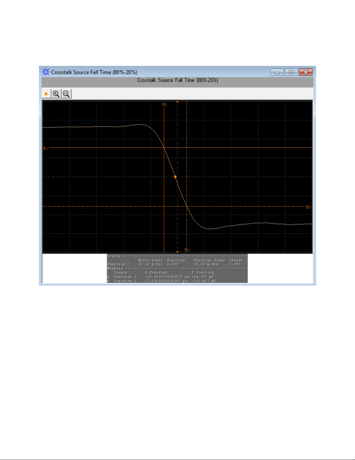
Figure 20 Reference Image for Crosstalk Source Fall Time (80%-20%)
After the crosstalk source calibration is applied to all the input lanes of
the XLPPI host, the SFP+ test application executes various tests based on
the following test pattern to conform that the test results at the output
lane and signals are as per the conformance limits in the specification.
Test Pattern 8180
Test pattern 8180 represents a repeating square wave which consists of
eight continuous 1s followed by eight continuous 0s. This test pattern is
used to check the XLPPI compliance against the IEEE 802.3 specification
for the following tests:
• Output Rise Time (20%- 80%) Test/Output Fall Time (80%- 20%) Test
• Qsq (V/V) Test
64 SFP+ Compliance Testing Methods of Implementation
Page 65

Host Transmitter Output Electrical Specifications Tests 4
NOTE
NOTE
Output Rise Time (20%-80%) Test/Output Fall Time (80%-20%) Test
The Output Rise Time (20%-80%)/Output Fall Time (80%-20%) test measures the
rise and fall time of a XLPPI host transmitter respectively. The purpose of
this test is to verify that the rise or fall time of the XLPPI host
transmitter is within the conformance limits of 28 ps as per the
specification.
For information about the connection diagram, refer to “Connecting
the Host Transmitter Board" on page 20.
Configuring Test Parameter
To execute the Output Rise Time (20%-80%)/Output Fall Time (80%-20%) test, you
need to configure the #Averages(16) parameter. The #Averages(16)
parameter is used to reduce the effect of noise on the measurement. The
value of one average is calculated by averaging multiple acquisitions of the
waveform. Sixteen (16) is used as the default value but you can increase
or decrease this number to reduce or upsurge the effects of noise and
random signal variations.
Averaging can be used to reduce measurement noise and increase
measurement resolution; however, the specification does not provide
any constraints on how much averaging may be used but increase in
the value of the #Averages(16) parameter leads to diminishing results.
Understanding the Test Flow
The following references from the IEEE- 802.3 specification are considered
to check the compliance of the DUT:
[1] IEEE802.3ba- 2010, Annex 86A, Table 86A- 1
[2] IEEE802.3ba- 2010, Section 86A.5.3.3
[3] IEEE802.3, Section 68.6.2
The SFP+ test application performs the following automated steps for
measuring the Output Rise Time (20%-80%)/Output Fall Time (80%-20%) test based
on the above mentioned references:
1 Triggers one cycle of the 8180 waveform on the rising edge.
2 Analyzes the rise/fall time of the signal at logic 0 and logic 1 voltage
levels. The measurement procedure of the logic 0 and logic 1 state is
defined as per reference [3]. The average voltage level in the central
20% of each time interval is measured.
SFP+ Compliance Testing Methods of Implementation 65
Page 66

4 Host Transmitter Output Electrical Specifications Tests
3 Measures the 20% to 80% rise time using the logic 0 voltage level as
base level and logic 1 voltage level as top level of the isolated edges in
case of the Output Rise Time (20%-80%) test. Measures the 80% to 20% fall
time using the logic 1 voltage level as base level and logic 0 voltage
level as top level of the isolated edges in case of the Output Fall Time
(80%-20%) test. From reference [2], the optical modulation amplitude
(OMA) test pattern (eight ones, eight zeros) is being used as the
normative test pattern. The 0% level and 100% level are the voltage
levels of the logic 0 state and logic 1 state respectively as defined by
the xMA measurement procedure in the specification.
4 Analyzes the signal and verifies that this is as per the conformance
limits as specified in reference [1].
Viewing Test Results
For each test trial, its result is displayed on the Results tab. Click the
desired test to view its result. Details of the test results are described in
the lower pane. A sample reference image based on the measured values is
captured by the oscilloscope. You can click the sample reference image to
view the details. For information about the test results, refer to Viewing
Results in the online help.
66 SFP+ Compliance Testing Methods of Implementation
Page 67
Host Transmitter Output Electrical Specifications Tests 4
Q
sq
1
SNR
---------- -
=
Q
sq
VMA
n1 n0+
-----------------------
=
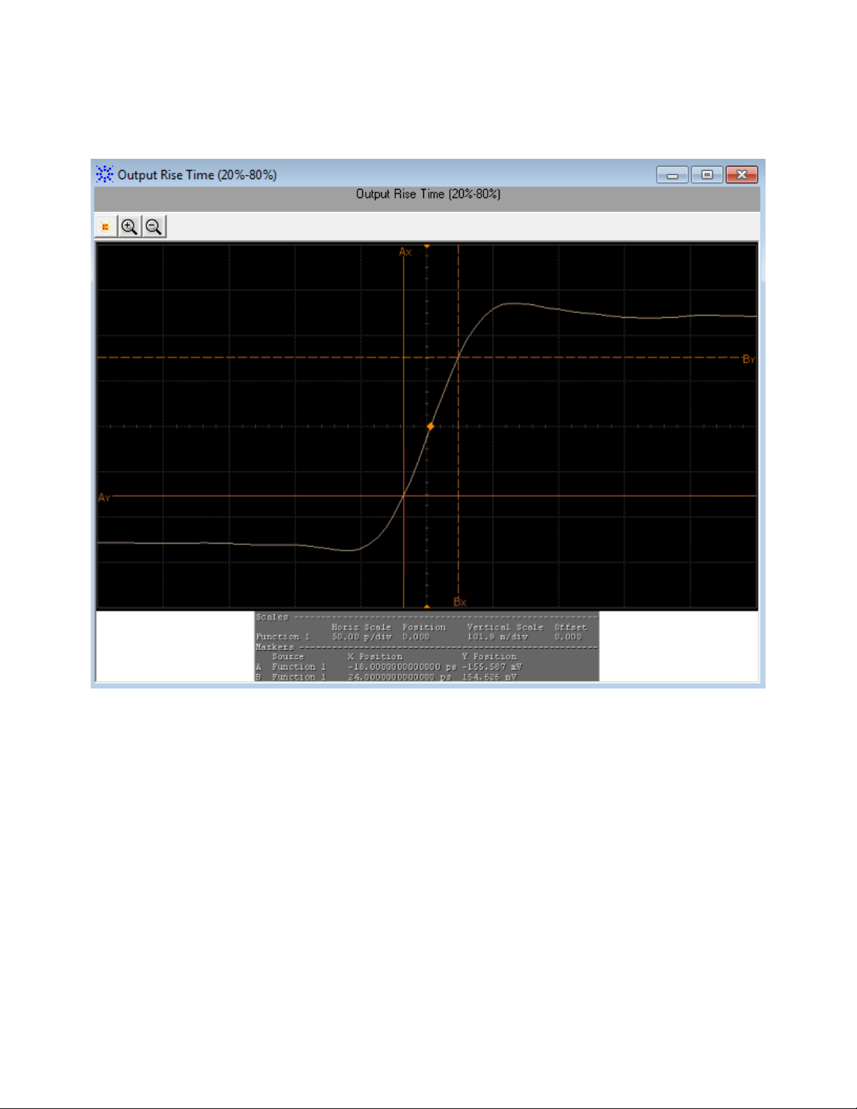
Figure 21 Reference Image for Output Rise Time (20%-80%) Test
Qsq (V/V) Test
The Qsq (V/V) test is a measure of reciprocal of signal to noise ratio (SNR)
of the XLPPI host transmitter.
As per IEEE802.3ba- 2010, Section 86A.5.3.5, Q
following formula:
is calculated using the
sq
SFP+ Compliance Testing Methods of Implementation 67
Page 68

4 Host Transmitter Output Electrical Specifications Tests
NOTE
whereby,
• n1 is the RMS noise of logic one
• n2 is the RMS noise of logic zero
The purpose of this test is to verify that the signal to noise ratio of the
XLPPI host transmitter is within the conformance limits of 45.
For information about the connection diagram, refer to “Connecting
the Host Transmitter Board" on page 20.
Configuring Test Parameter
To execute the Qsq (V/V) test, you need to configure the #Waveforms(60)
parameter. The #Waveforms(60) parameter is used to reduce the effect of
noise on the measurement. Sixty (60) is used as the default value but you
can increase or decrease this number to reduce or upsurge the effects of
noise and random signal variations.
Understanding the Test Flow
The following references from the IEEE802.3 specifications are considered
to check the compliance of the DUT:
[1] IEEE802.3ba- 2010, Annex 86A, Table 86A- 1
[2] IEEE802.3ba- 2010, Section 86A.5.3.5
The SFP+ test application performs the following automated steps for
executing the Qsq (V/V) test based on the above mentioned references:
1 Triggers one cycle of the 8180 waveform on the rising edge.
2 Analyzes the rise/fall time of the signal at logic 0 and logic 1 voltage
levels.
3 Measures the value for VMA using the logic 0 voltage level as base level
and logic 1 voltage level. For information on the measurement of VMA,
refer to
page 34.
4 Measures the root mean square (RMS) noise for the logic 0 and logic 1
levels. From reference [2], the optical modulation amplitude (OMA) test
pattern (eight ones, eight zeros) is being used as the normative test
pattern. The 0% level and 100% level are the voltage levels of the logic 0
state and logic 1 state respectively as defined by the xMA measurement
procedure in the specification.
“Voltage Modulation Amplitude for Cu (VMA) (p- p) Test" on
5 Calculates the value of Q
6 Analyzes the signal and verify that this is as per the conformance limits
of 45 as specified in reference [1].
68 SFP+ Compliance Testing Methods of Implementation
using the formula mentioned above.
sq
Page 69
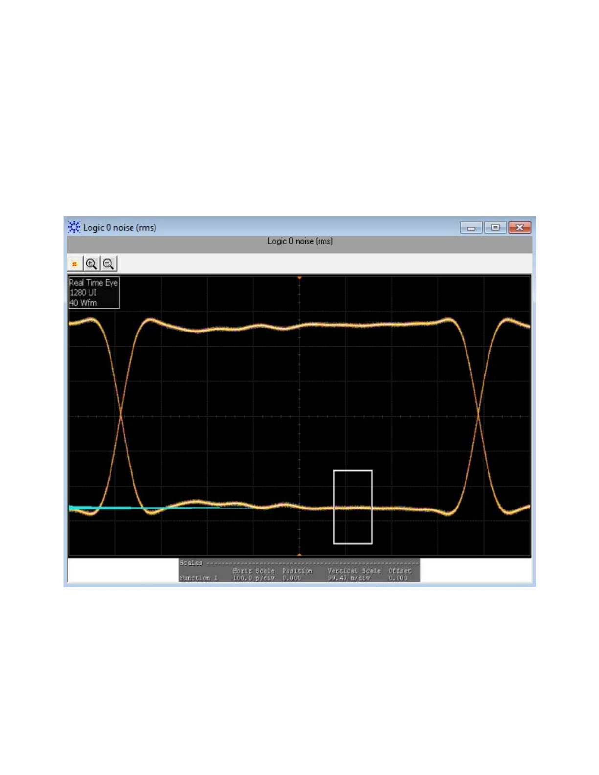
Host Transmitter Output Electrical Specifications Tests 4
Viewing Test Results
For each test trial, its result is displayed on the Results tab. Click the
desired test to view its result. Details of the test results are described in
the lower pane. A sample reference image based on the measured values is
captured by the oscilloscope. You can click the sample reference image to
view the details. For information about the test results, refer to Viewing
Results in the online help.
Figure 22 Reference Image for Qsq (V/V) Test for Logic 0
SFP+ Compliance Testing Methods of Implementation 69
Page 70

4 Host Transmitter Output Electrical Specifications Tests
NOTE
Figure 23 Reference Image for Qsq (V/V) Test for Logic 1
Test Pattern PRBS9
PRBS9 test pattern represents a pseudorandom binary sequence with a
repetition period of 2
the Data Dependent Pulse Width Shrinkage (DDPWS) (p-p) test.
Data Dependent Pulse Width Shrinkage (DDPWS) (p-p) Test
The Data Dependent Pulse Width Shrinkage (DDPWS) (p-p) test measures the
value of DDPWS from peak- to- peak (p- p) of a XLPPI host transmitter.
9
- 1. This test pattern is used to measure the jitter for
For information about the connection diagram, refer to “Connecting
the Host Transmitter Board" on page 20.
70 SFP+ Compliance Testing Methods of Implementation
Page 71

Host Transmitter Output Electrical Specifications Tests 4
DDPWS T min t2t1– t3t2– t
256 1+t256
––=
Understanding the Test Flow
The following references from the SFF- 8431 specification are considered to
check the compliance of the DUT:
[1] IEEE802.3ba- 2010, Annex 86A, Table 86A- 1
[2] IEEE802.3ba- 2010, Section 86A.5.3.5
The SFP+ test application performs the following automated steps for
executing the Data Dependent Pulse Width Shrinkage (DDPWS) (p-p) test based
on the above mentioned references:
1 Triggers 1024 cycles of the PRBS9 waveform.
2 Turns on EZJIT complete and sets the pattern analysis mode to
periodic. As the PRBS9 pattern is relatively short, the DDPWS pattern
completes in periodic pattern analysis mode.
3 Analyzes the signal and verifies that this is as per the conformance
limits of 0.07UI as specified in reference [1]. For a capture with n
edges, DDPWS is measured as the difference between one symbol period
and the minimum pulse width of the entire capture. It is given by the
algorithm:
whereby, T is the symbol period of the data stream and tn is the
crossing time of edge n.
Viewing Test Results
For each test trial, its result is displayed on the Results tab. Click the
desired test to view its result. Details of the test results are described in
the lower pane. A sample reference image based on the measured values is
captured by the oscilloscope. You can click the sample reference image to
view the details. For information about the test results, refer to Viewing
Results in the online help.
SFP+ Compliance Testing Methods of Implementation 71
Page 72
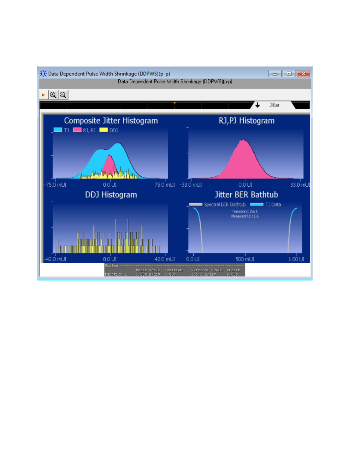
4 Host Transmitter Output Electrical Specifications Tests
Figure 24 Reference Image for DDPWS (p-p) Test
Test Pattern PRBS31
PRBS31 test pattern represents a pseudorandom binary sequence with a
repetition period of 2
49.2.8. This test pattern is used to check the compliance of the XLPPI host
transmitter output using the following tests:
• AC Common Mode Output Voltage (rms) Test
• Single Ended Output Voltage (Positive) Test/Single Ended Output
Voltage (Negative) Test
• J2 Jitter (p- p) Test
• J9 Jitter (p- p) Test
• Eye Mask Hit Ratio Test
31
- 1. The sequence is defined in IEEE Std 802.3,
72 SFP+ Compliance Testing Methods of Implementation
Page 73

Host Transmitter Output Electrical Specifications Tests 4
NOTE
AC Common Mode Output Voltage (rms) Test
The AC Common Mode Output Voltage (rms) test measures the output AC
common mode voltage of a XLPPI host transmitter.
For information about the connection diagram, refer to “Connecting
the Host Transmitter Board" on page 20.
Understanding the Test Flow
The following references from the IEEE802.3 specification are considered
to check the compliance of the DUT:
[1] IEEE802.3ba- 2010, Annex 86A, Table 86A- 1
[2] IEEE802.3ba- 2010, Section 86A.5.3.1
The SFP+ test application performs the following automated steps for
executing the AC Common Mode Output Voltage (rms) test:
1 Triggers the PRBS31 waveform.
2 Folds the PRBS31 waveform.
3 Places a histogram with a width of 1 unit interval across the folded
waveform. According to the procedure specified in reference [2], the
RMS AC common mode voltage is measured by applying a histogram
over one UI of the common mode signal. Multiple unit intervals are
overlapped to get an averaged measurement. The scope is set to free
run triggering as the oscilloscopes do not have the memory depth for 1
cycle of the PRBS31 waveform. For a compliant XLPPI host transmitter,
reference [1] specifies a maximum AC common mode voltage of 15mV,
rms.
Viewing Test Results
For each test trial, its result is displayed on the Results tab. Click the
desired test to view its result. Details of the test results are described in
the lower pane. A sample reference image based on the measured values is
captured by the oscilloscope. You can click the sample reference image to
view the details. For information about the test results, refer to Viewing
Results in the online help
SFP+ Compliance Testing Methods of Implementation 73
Page 74
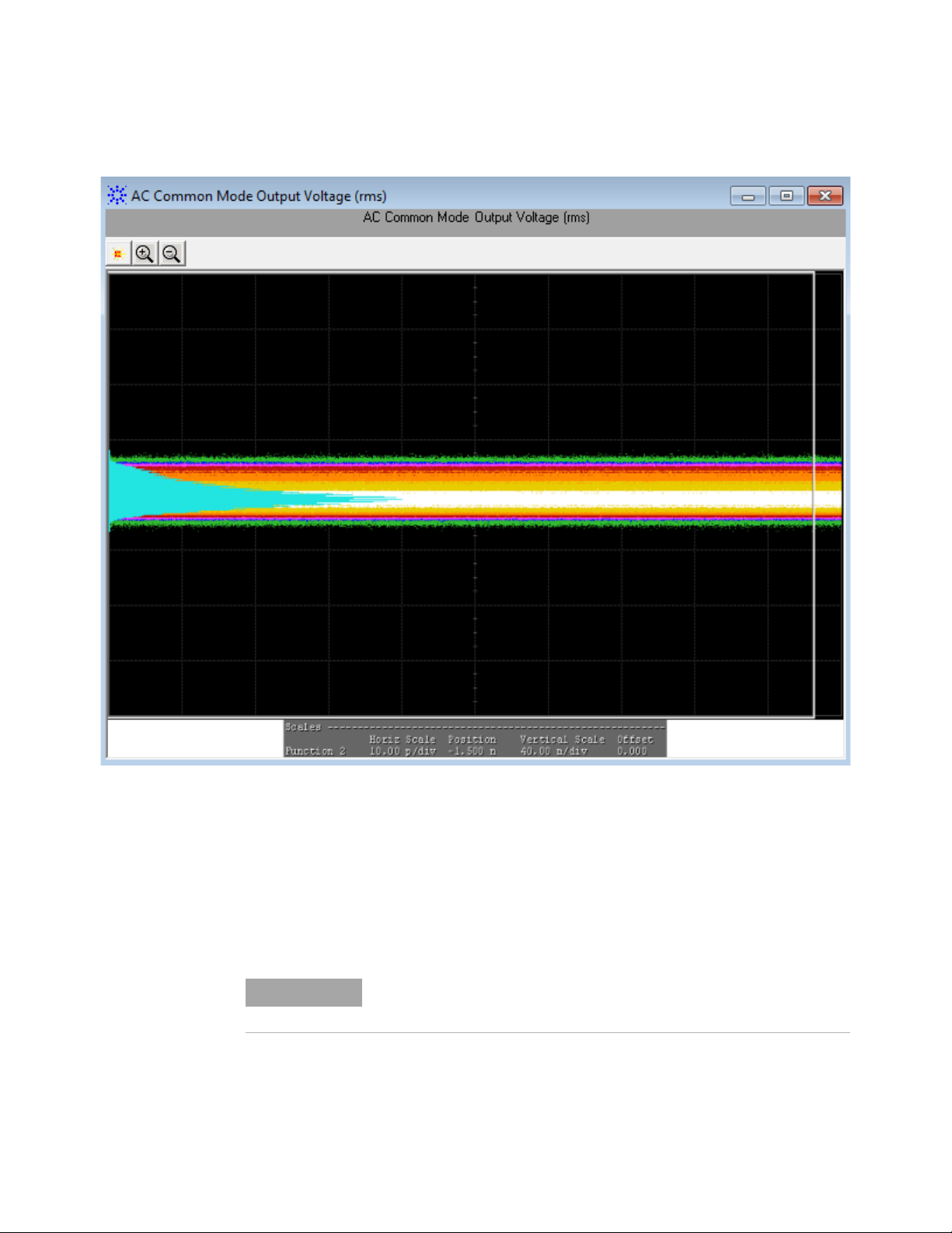
4 Host Transmitter Output Electrical Specifications Tests
NOTE
.
Figure 25 Reference Image for AC Common Mode Output Voltage (rms) Test
Single Ended Output Voltage (Positive) Test/Single Ended Output Voltage (Negative) Test
The Single Ended Output Voltage (Positive)/Single Ended Output Voltage (Negative)
test measures the voltage range of the positive (TX+) and negative (TX-)
signals respectively of a XLPPI host transmitter.
For information about the connection diagram, refer to “Connecting
the Host Transmitter Board" on page 20.
74 SFP+ Compliance Testing Methods of Implementation
Page 75

Host Transmitter Output Electrical Specifications Tests 4
Understanding the Test Flow
The following reference from the IEEE802.3 specification is considered to
check the compliance of the DUT:
[1] IEEE802.3ba- 2010, Annex 86A, Table 86A- 1
The SFP+ test application performs the following automated steps for
executing the Single Ended Output Voltage (Positive)/Single Ended Output Voltage
(Negative) test based on the above mentioned reference:
1 Triggers the PRBS31 waveform.
2 Measures the peak- to- peak (p- p) voltage. For a compliant XLPPI host
transmitter, reference [1] specifies the single ended voltage range to be
between - 0.3V and 4.0V.
Viewing Test Results
For each test trial, its result is displayed on the Results tab. Click the
desired test to view its result. Details of the test results are described in
the lower pane. A sample reference image based on the measured values is
captured by the oscilloscope. You can click the sample reference image to
view the details. For information about the test results, refer to Viewing
Results in the online help.
SFP+ Compliance Testing Methods of Implementation 75
Page 76
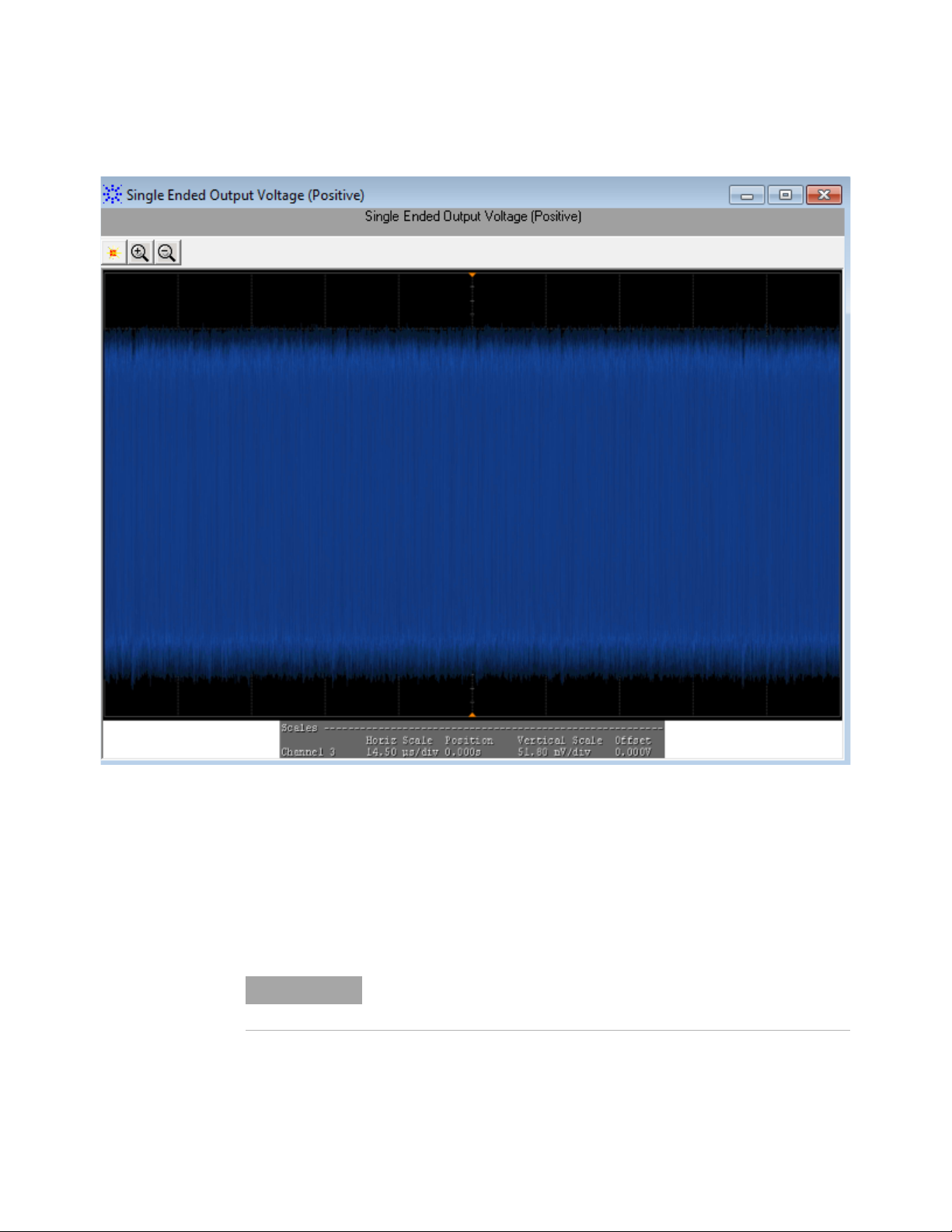
4 Host Transmitter Output Electrical Specifications Tests
NOTE
Figure 26 Reference Image for Single Ended Output Voltage (Positive) Test
J2 Jitter (p-p) Test
The J2 Jitter (p-p) test measures the J2 jitter of a XLPPI host transmitter
and is defined as the time interval that includes all but 10
distribution, which is the time interval from the 0.5
percentile of the jitter histogram.
For information about the connection diagram, refer to “Connecting
the Host Transmitter Board" on page 20.
th
-2
of the jitter
to the 99.5th
76 SFP+ Compliance Testing Methods of Implementation
Page 77

Host Transmitter Output Electrical Specifications Tests 4
NOTE
Understanding the Test Flow
The following reference from the IEEE802.3 specification is considered to
check the compliance of the DUT:
[1] IEEE802.3ba- 2010, Annex 86A, Table 86A- 1
The SFP+ test application performs the following automated steps for
executing the J2 Jitter (p-p) test based on the above mentioned reference:
1 Triggers the PRBS31 waveform.
2 Turns on EZJIT Complete, and set the pattern analysis mode to Arbitrary
as the signal is relatively long.
3 Obtains the results for J2 for a compliant XLPPI host transmitter.
Reference [1] specifies a maximum J2 of 0.17UI, peak- to- peak.
The clock recovery method used is a second order PLL with a loop
bandwidth of 4MHz and a slope of -20dB/decade with a peaking of
0.1dB.
Viewing Test Results
For each test trial, its result is displayed on the Results tab. Click the
desired test to view its result. Details of the test results are described in
the lower pane. A sample reference image based on the measured values is
captured by the oscilloscope. You can click the sample reference image to
view the details. For information about the test results, refer to Viewing
Results in the online help.
SFP+ Compliance Testing Methods of Implementation 77
Page 78
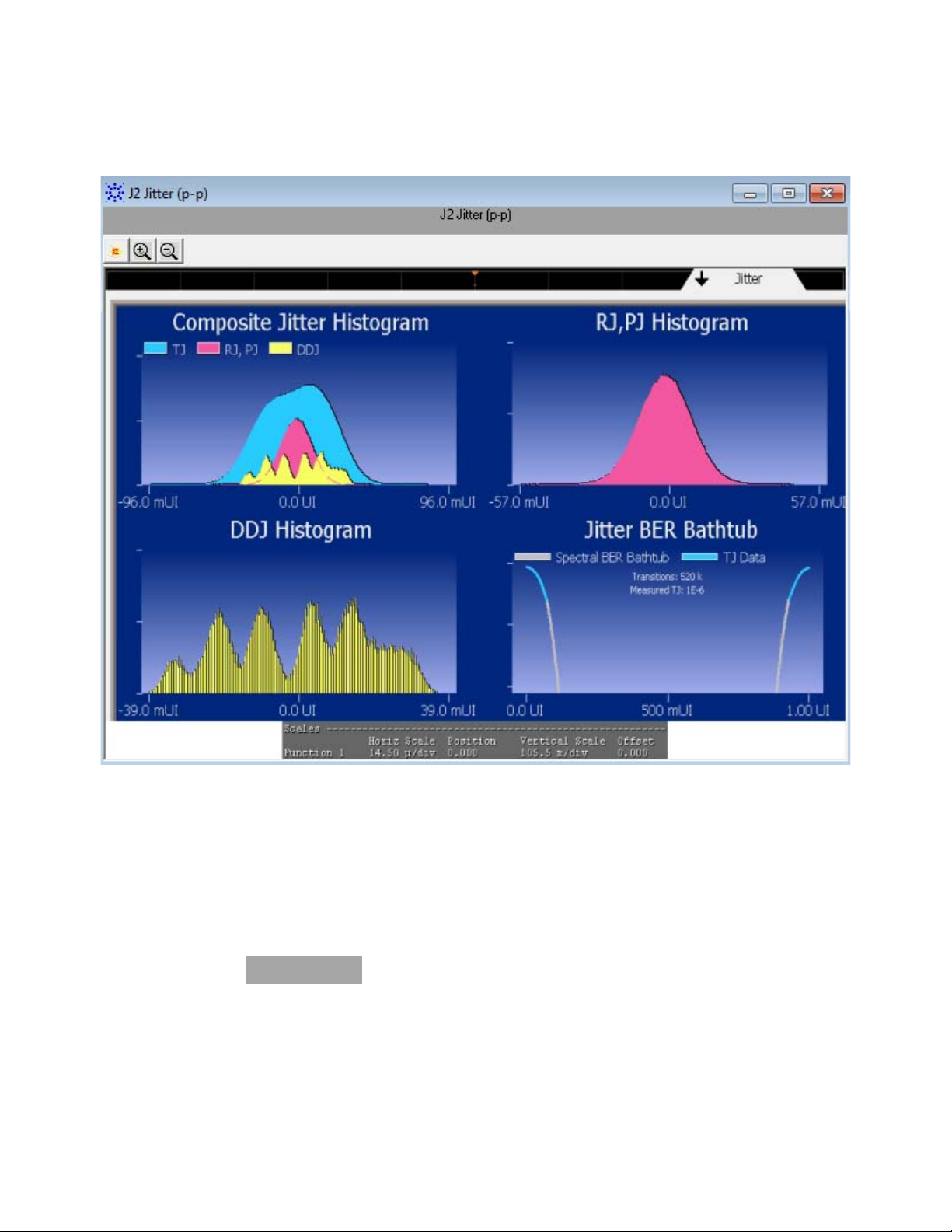
4 Host Transmitter Output Electrical Specifications Tests
NOTE
Figure 27 Reference Image for J2 Jitter (p-p) Test
J9 Jitter (p-p) Test
The J9 Jitter (p-p) test measures the J9 jitter of a XLPPI host transmitter
and is defined as the time interval that includes all but 10
distribution.
For information about the connection diagram, refer to “Connecting
the Host Transmitter Board" on page 20.
-9
of the jitter
78 SFP+ Compliance Testing Methods of Implementation
Page 79

Host Transmitter Output Electrical Specifications Tests 4
NOTE
Understanding the Test Flow
The following reference from the IEEE802.3 specification is considered to
check the compliance of the DUT:
[1] IEEE802.3ba- 2010, Annex 86A, Table 86A- 1
The SFP+ test application performs the following automated steps for
executing the J9 Jitter (p-p) test based on the above mentioned reference:
1 Triggers the PRBS31 waveform.
2 Turns on EZJIT Complete, and set the pattern analysis mode to Arbitrary
as the signal is relatively long.
3 Obtains the results for J9 for a compliant XLPPI host transmitter.
Reference [1] specifies a maximum J9 of 0.29UI, peak- to- peak.
The clock recovery method used is a second order PLL with a loop
bandwidth of 4MHz and a slope of -20dB/decade with a peaking of
0.1dB.
Viewing Test Results
For each test trial, its result is displayed on the Results tab. Click the
desired test to view its result. Details of the test results are described in
the lower pane. A sample reference image based on the measured values is
captured by the oscilloscope. You can click the sample reference image to
view the details. For information about the test results, refer to Viewing
Results in the online help.
SFP+ Compliance Testing Methods of Implementation 79
Page 80

4 Host Transmitter Output Electrical Specifications Tests
NOTE
Figure 28 Reference Image for J9 Jitter (p-p) Test
Eye Mask Hit Ratio Test
The Eye Mask Hit Ratio test measures the mask hit ratio of XLPPI host
transmitter. The eye mask is defined by the parameters X1, X2, Y1, and
Y2. The eye is defined as measured using a receiver with an electrical
- 3dB bandwidth of 12GHz such as Bessel- Thomson response. As per the
relevant standard, the mask hit ratio is set to 5*10
For information about the connection diagram, refer to “Connecting
the Host Transmitter Board" on page 20.
-5
.
80 SFP+ Compliance Testing Methods of Implementation
Page 81

Host Transmitter Output Electrical Specifications Tests 4
NOTE
Hit Ratio
Total Mask Violations
Total Number of Samples in 1UI
-------------------------------------------------------------------=
Total Number of Samples in 1 UI Sampling Rate 1UI=
Understanding the Test Flow
The following reference from the IEEE802.3 specification is considered to
check the compliance of the DUT:
[1] IEEE802.3ba- 2010, Annex 86A, Table 86A- 1
The SFP+ test application performs the following automated steps for
executing the Eye Mask Hit Ratio test:
1 Enables the Mask Test and loads the test. Enabling the Mask Test allows
you to conform the waveform as per the industry standards.
2 Triggers the PRBS31 waveform for the Mask Test.
3 Calculates the mask hit ratio. For a compliant XLPPI host transmitter,
reference [1] specifies an Eye Mask Hit Ratio that is less than 5x10
The eye mask hit ratio is calculated using the formula:
And the total number of samples in 1UI is given by:
The clock recovery method used is a second order PLL with a loop
bandwidth of 4MHz and a slope of -20dB/decade with a peaking of
0.1dB.
-15
Viewing Test Results
For each test trial, its result is displayed on the Results tab. Click the
desired test to view its result. Details of the test results are described in
the lower pane. A sample reference image based on the measured values is
captured by the oscilloscope. You can click the sample reference image to
view the details. For information about the test results, refer to Viewing
Results in the online help.
.
SFP+ Compliance Testing Methods of Implementation 81
Page 82
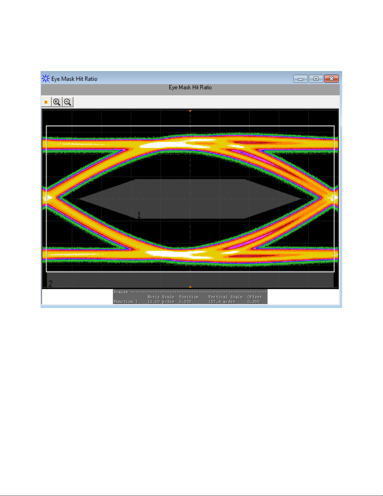
4 Host Transmitter Output Electrical Specifications Tests
Figure 29 Reference Image for Eye Mask Hit Ratio Test
82 SFP+ Compliance Testing Methods of Implementation
Page 83
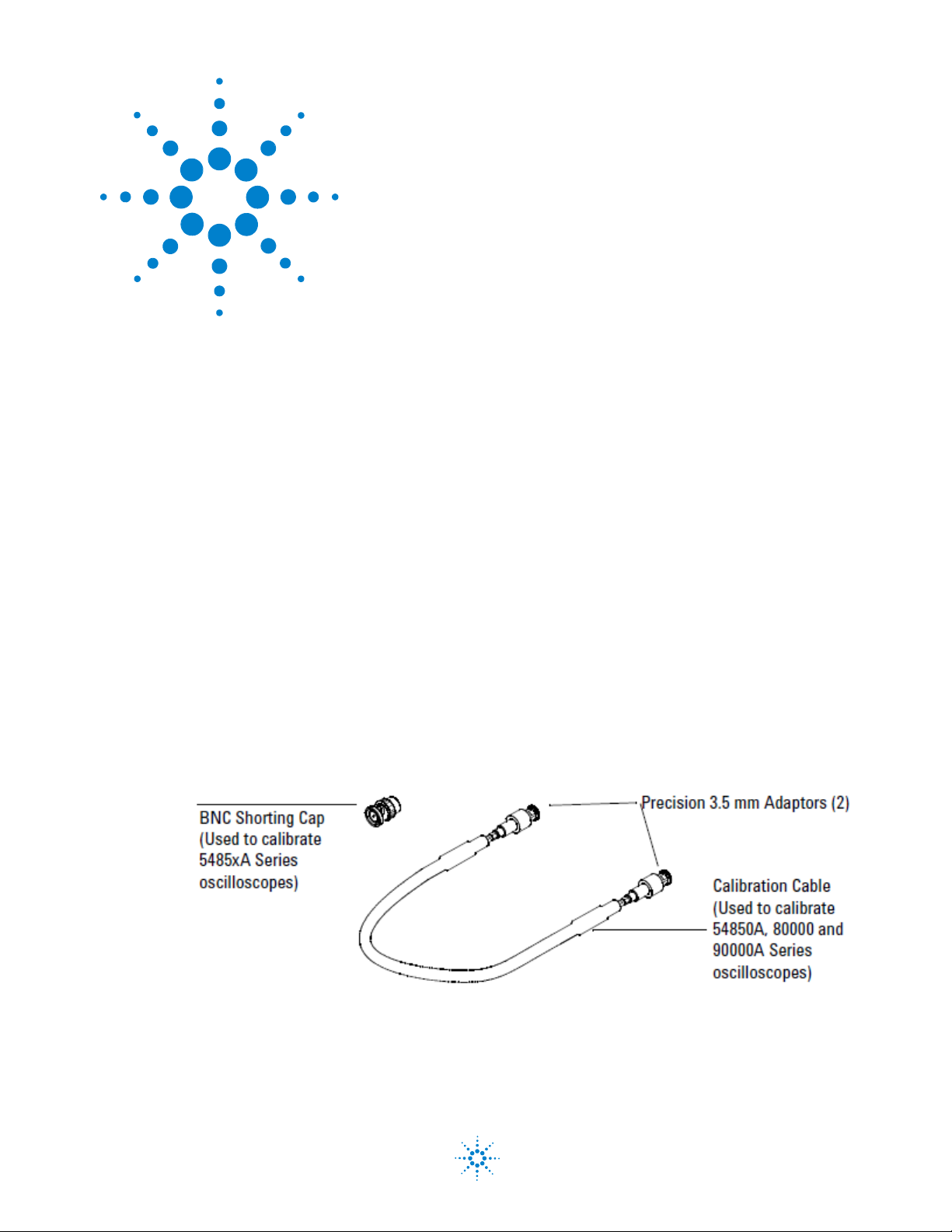
N6468A SFP+ Compliance Test application
Methods of Implementation
5
Calibrating the Infiniium Oscilloscope
and Probe
Required Equipment for Calibration 83
Internal Calibration 84
This appendix describes the Agilent Infiniium digital storage oscilloscope
calibration procedures.
Required Equipment for Calibration
To calibrate the Infiniium oscilloscope in preparation for running the SFP+
automated tests, you need the following equipment:
• Keyboard, qty = 1, (provided with the Agilent Infiniium oscilloscope).
• Mouse, qty = 1, (provided with the Agilent Infiniium oscilloscope).
• Precision 3.5 mm BNC to SMA male adapter, Agilent p/n 54855- 67604,
= 2, (provided with the Agilent Infiniium oscilloscope).
qty
• Calibration cable (provided with the 54850A series, 80000 and 90000A
series Infiniium oscilloscopes). Use a good quality 50
• BNC shorting cap (provided with the Agilent Infiniium oscilloscope).
Figure 30 Accessories provided with the Agilent Infiniium Oscilloscope
BNC cable.
Agilent Technologies
83
Page 84

5 Calibrating the Infiniium Oscilloscope and Probe
Internal Calibration
To perform an internal diagnostic and calibration cycle for the oscilloscope
(referred as Calibration for the Agilent oscilloscope), follow these steps:
1 Set up the oscilloscope with the following steps:
a Connect the keyboard, mouse, and power cord to the rear of the
oscilloscope.
b Plug in the power cord.
c Turn on the oscilloscope by pressing the power button located on the
lower left of the front panel.
d Allow the oscilloscope to warm up at least 30 minutes prior to
starting the calibration procedure in step 3 below.
2 Locate and prepare the accessories that will be required for the
internal calibration:
a Locate the BNC shorting cap.
b Locate the calibration cable.
c Locate the two Agilent precision SMA/BNC adapters.
d Attach one SMA adapter to the other end of the calibration cable -
hand tighten snugly.
e Attach another SMA adapter to the other end of the calibration cable
- hand tighten snugly.
84 SFP+ Compliance Testing Methods of Implementation
Page 85

Calibrating the Infiniium Oscilloscope and Probe 5
3 Referring to Figure 31 below, perform the following steps:
a Click on the Utilities>Calibration menu to open the Calibration dialog
box.
Figure 31 The Calibration Option
4 Referring to Figure 32 below, perform the following steps to start the
calibration:
a Uncheck the Cal Memory Protect checkbox.
b Click the Start button to begin the calibration.
c Follow the on- screen instructions.
SFP+ Compliance Testing Methods of Implementation 85
Page 86
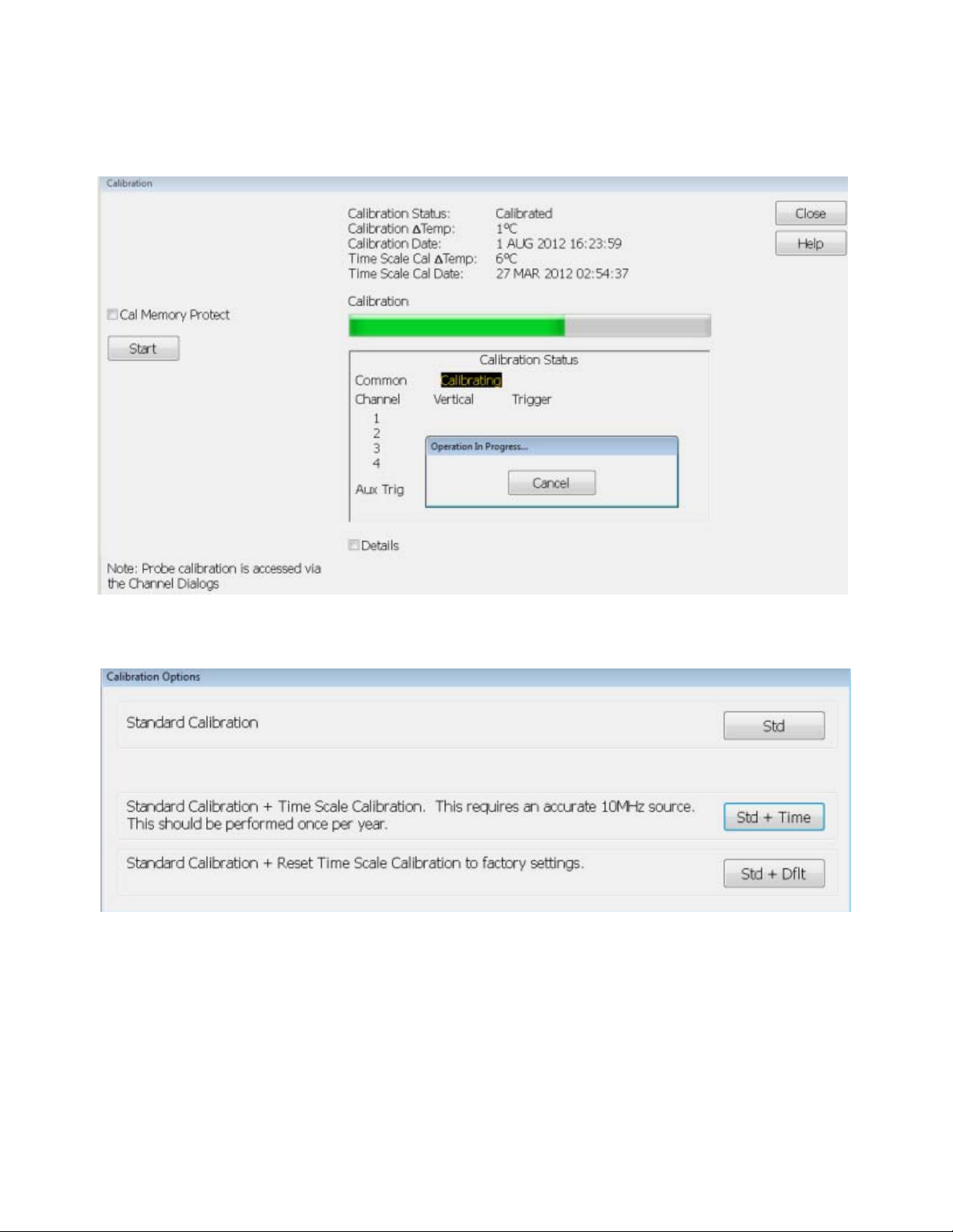
5 Calibrating the Infiniium Oscilloscope and Probe
d During the calibration of channel 1, if you are prompted to perform
a Time Scale Calibration, as shown in
Figure 32 below.
86 SFP+ Compliance Testing Methods of Implementation
Page 87

Calibrating the Infiniium Oscilloscope and Probe 5
NOTE
Figure 32 Time Scale Calibration Dialog box
e Click on the Default button to continue the calibration, using the
Factory default calibration factors.
f When the calibration procedure is complete, you will be prompted
with a Calibration Complete message window. Click the OK button to
close this window.
g Confirm that the Vertical and Trigger Calibration Status for all
Channels passed.
h Click the Close button to close the calibration window.
i The internal calibration is completed.
j Read receiver below.
These steps do not need to be performed every time a test is run. However, if the ambient
temperature changes more than 5 degrees Celsius from the calibration temperature, this
calibration should be performed again. The delta between the calibration temperature and
the present operating temperature is shown in the Utilities>Calibration menu.
SFP+ Compliance Testing Methods of Implementation 87
Page 88

5 Calibrating the Infiniium Oscilloscope and Probe
88 SFP+ Compliance Testing Methods of Implementation
Page 89

Index
Symbols
#Averages(16), 29, 65
#Hits(100), 42
#Waveforms(60, 31, 68
Numerics
10GSFP+ Cu, 28
40Gb/s parallel physical interface, 57
B
blocking capacitors, 18
BNC to SMA converter, 18
C
calibrating the oscilloscope, 83
calibration cable, 83
clock recovery method, 55
D
DDJ, 38
DDPWS, 40
E
minimum version of the Infiniium software, 14
O
optical modulation amplitude, 29
P
parameters, eye mask, 54
physical medium dependent, 57
PRBS9, 37, 70
precision probe/cable, 24
R
relative noise, 31
required equipment for calibration, 83
required fixtures and accessories, 16
rms technique, 31
S
SFI, 28
SFP+ compliance test application, 9
SMA cable, 20
SMA to SMA converter, 18
standard reference, 9
switch matrix, 24
enhanced small form factor pluggable, 28
EZJIT, 38
H
host compliance board, 20
HTML report, 23
T
task flow, 22
threshold-crossing time, 38
V
voltage modulation amplitude, 31
I
W
in this book, 5
InfiniiSim, 24
internal calibration, 84
waveform distortion penalty, 44
X
L
license key, installing, 14
xMA, 30
M
mask test, 55
SFP+ Compliance Testing Methods of Implementation 89
Page 90

Index
90 SFP+ Compliance Testing Methods of Implementation
Loading...