

Page 1

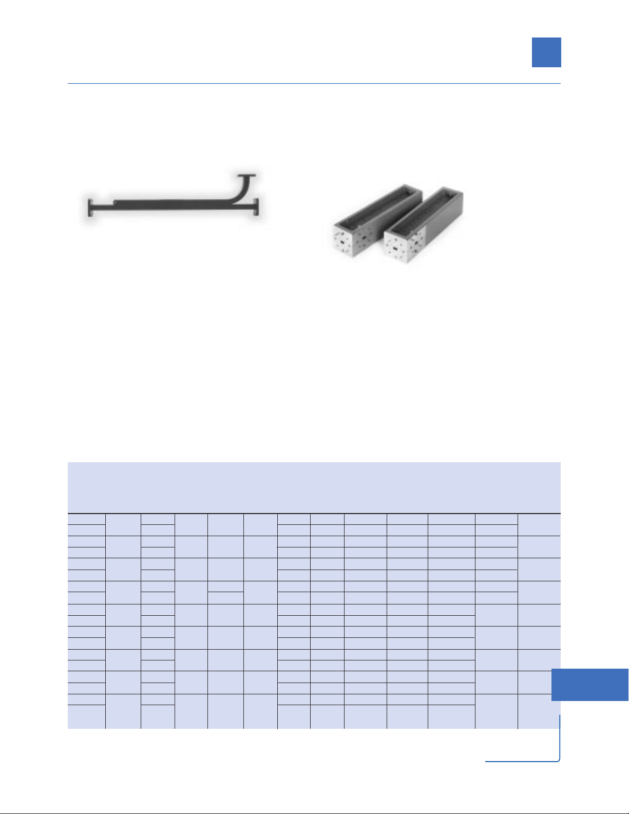
Selection Guide
Frequency Coverage by Band – GHz
XPKRQUVW
HP Model
Number 8.20- 12.4- 18.0- 26.5- 33.0- 40.0- 50.0- 75.0-
Type Uses Series
1
12.4 18.0 26.5 40.0 50.0 60.0 75.0 110.0
Adapters Interconnect coaxial-waveguide system 281A
2
XXXXX
281B XXXXX
281C XXX XX
281D XX
Variable Measure reflection coefficient, insertion 382A XXXX
Attenuators loss, transfer characteristics by RF
substitution source mismatch
Detectors Detect RF power, CW or pulsed; measure 422C XX
reflection coefficient, insertion loss
Directional Sample high power, level power, measure 752C XXXXXXXX
Couplers reflection coefficient, reduce mismatch 752D XXXXXXX
752CS, DS X
Isolators Reduce mismatch at mm-wave frequencies 365A XX XXX
Mixers
3
Extend spectrum analyzer frequency 11970K X
range to millimeter band 11970R X
11970Q X
11970U X
11970V X
11970W
Network
4
Waveguide calibration kits 11644A XXXXXXXX
Analyzer Waveguide verification kits 11645A XXXXX
Terminations Fixed loads for terminating waveguide 910A XXXX
systems, sliding loads for separating load 910B X
reflections from other system reflections 910C X
914B X
1
For complete model number, add the appropriate waveguide band designator as a prefix to the model number (except mixers)
e.g. the model number for a coax to waveguide adapter in “X” band would be X281A.
2
Also available in the following bands (in GHz): S (2.6 to 3.95), G (3.95 to 5.85), J (5.3 to 8.2), and H (7.05 to 10).
3
See Mixer section of this catalog for product details.
4
See Network Analyzer section of this catalog for product details.
177
18
Waveguide Accessories
Visit our web site http://www.hp.com/go/mta
Page 2

Coaxial to Waveguide Adapters
HP 281 Series
HP 281A,B,C series adapters transform waveguide transmission line into 50 Ω coaxial line.
Power can be transmitted in either direction, and each adapter covers the full frequency range
of its waveguide band with SWR less than 1.3.
Waveguide1Flange
1
Frequency Designator Designator Shipping
HP Range Maximum EIA UG-( )/U Coaxial Length Weight
Model (GHz) SWR MIL-W-85/( ) MIL-F-3922/( ) Connector mm (in) kg (lb)
S281A 2.6 to 3.95 1.25 WR-284 584 N (f) 140 (5.5) 0.54 (1.19)
1-041 56B-002
G281A 3.95 to 5.85 1.25 WR-187 407 N (f) 95 (3.75) 0.27 (0.5)
1-053 57B-001
J281A 5.3 to 8.2 1.3 WR-137 441 N (f) 51 (2) 0.45 (1)
1-065 55B-002
H281A 7.05 to 10 1.25 WR-112 138 N (f) 41 (1.63) 0.45 (1)
1-071 54C-006
X281A 8.2 to 12.4 1.25 WR-90 135 N (f) 35 (1.38) 0.45 (1)
1-077 54C-008
X281C 8.2 to 12.4 1.05 WR-90 135 APC-7 73 (2.88) 0.5 (1)
1-077 54C-008 Opt. 012: N (m)
Opt. 013: N (f)
P281B 12.4 to 18 1.25 WR-62 419 APC-7 64 (2.5) 0.5 (1)
1-090 70A-008 Opt. 013: N (f)
P281C 12.4 to 18 1.06 WR-62 419 APC-7 52 (2) 0.5 (1)
1-090 70A-008 Opt. 012: N (m)
Opt. 013: N (f)
K281C 18 to 26.5 1.07 WR-42 597 3.5 mm (f) 35 (1.38) 0.5 (1)
1-103 54C-002 Opt. 012: 3.5 mm (m)
R281A 26.5 to 40 1.13 WR-28 599 2.4 mm (f) 39 (1.5) 0.2 (0.5)
3-009
___
R281B 26.5 to 40 1.13 WR-28 599 2.4 mm (m) 39 (1.5) 0.2 (0.5)
3-009
___
Q281A 33 to 50 1.17 WR-22 383 2.4 mm (f) 39 (1.5) 0.2 (0.5)
3-013 67B-013
Q281B 33 to 50 1.17 WR-22 383 2.4 mm (m) 39 (1.5) 0.2 (0.5)
3-013 67B-013
U281A 40 to 60 1.17 WR-19 383 (mod) 1.85 mm (f) 39 (1.5) 0.2 (0.5)
___ ___
U281B 40 to 60 1.17 WR-19 383 (mod) 1.85 mm (m) 39 (1.5) 0.2 (0.5)
___ ___
V281A 50 to 64 1.17 WR-15 385 1.85 mm (f) 32 (1.25) 0.2 (0.5)
___ ___
V281B 50 to 64 1.17 WR-15 385 1.85 mm (m) 32 (1.25) 0.2 (0.5)
___ ___
V281C 50 to 75 1.16 WR-15 385 1.0 mm (f) 32 (1.25) 0.1 (0.2)
3-018 67B-002
V281D 50 to 75 1.16 WR-15 385 1.0 mm (m) 32 (1.25) 0.1 (0.2)
3-018 67B-002
W281C 75 to 110 1.16 WR-10 387 1.0 mm (f) 32 (1.25) 0.1 (0.2)
3-024 67B-010
W281D 75 to 110 1.16 WR-10 387 1.0 mm (m) 32 (1.25) 0.1 (0.2)
3-024 67B-010
Specifications
1
The Waveguide/Flange Designator is provided to determine interface dimensions and generic material of HP products.
178
Page 3

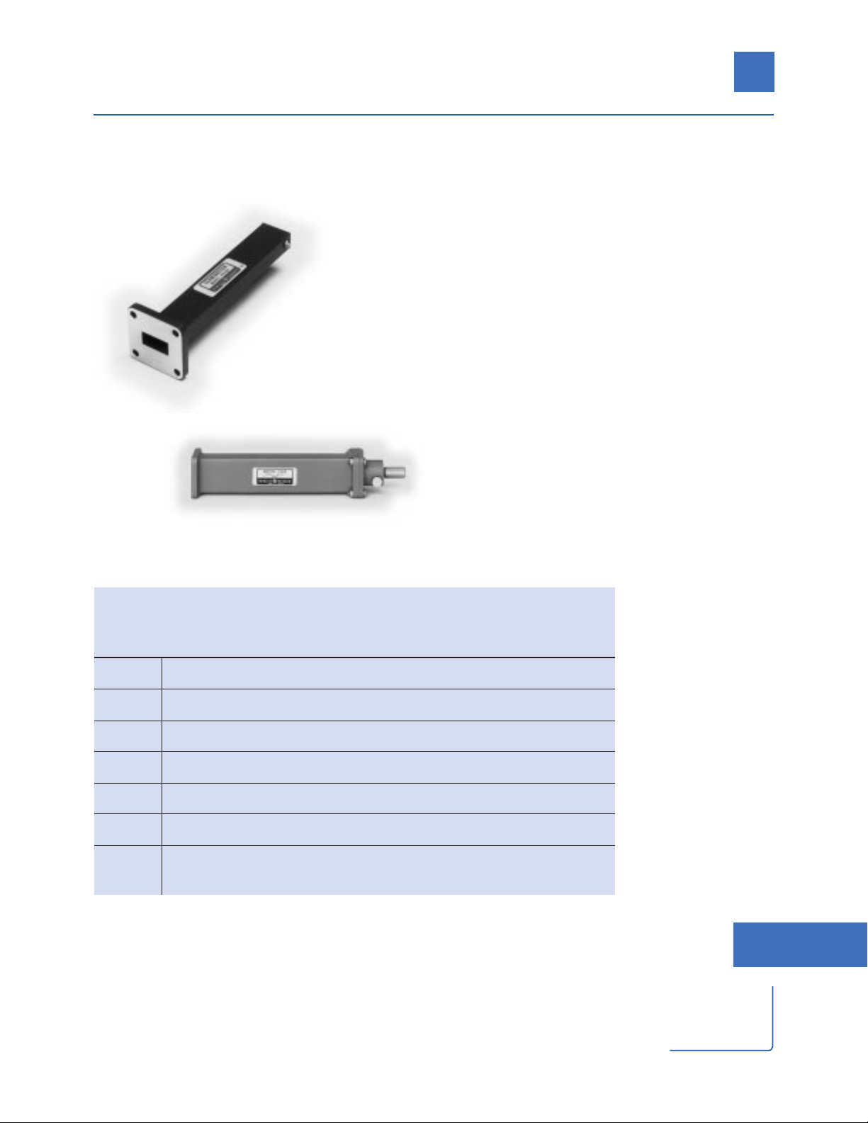
Variable Attenuators
HP 382A Series
The attenuation value of these direct-reading, precision attenuators depends on the rotation angle of
the resistive card, rather than on the resistivity value of the attenuating material. Therefore, they are
insensitive to changes in temperature and humidity which can affect the resistive card of ordinary
adjustable flap attenuators. The attenuation value is highly accurate and is stable from 0 to 50 dB.
The instruments feature large, easy-to-read dials, and can handle considerable microwave power.
Maximum Flange
1
Residual Maximum Waveguide1Designator
Frequency Attenuation Power Designator UG-( )/U Shipping
HP Range Maximum Attenuation Attenuation (0 dB Setting) (CW) EIA MIL-F- Dimensions Weight
Model (GHz) SWR Accuracy Range (dB) (dB) (watts) MIL-W-85/( ) 3922/( ) mm (in) kg (lb)
X382A 8.2 to 12.4 1 10 WR-90 135 397 x 194 x 119 3.6
1-077 54C-008 (15.63 x 7.63 (8)
x 4.69)
P382A 12.4 to 18
±2%
1 5 WR-62 419 318 x 197 x 121 3.6
of reading
1-090 70A-008 (12.5 x 7.75 (8)
1.15 or 0.1 dB, 0 to 50
x 4.75)
K382A 18 to 26.5
whichever
1 2 WR-42 595 194 x 156 x 121 2.7
is greater
1-103 54C-002 (7.63 x 6.13 (6)
x 4.75)
R382A 26.5 to 40 1 1 WR-28 599 162 x 156 x 121 2.7
3-008 54C-003 (6.38 x 6.13 (6)
x 4.75)
Specifications
HP P382A
HP R382A
1
The Waveguide/Flange Designator is provided to determine interface dimensions and generic material of HP products.
179
18
Waveguide Accessories
Visit our web site http://www.hp.com/go/mta
Page 4

HP K/R422C
The HP K422C (18 to 26.5 GHz)
and R422C (26.5 to 40 GHz) are
GaAs Planar-Doped Barrier diode
detectors. They both have
negative output polarity as
standard, and the HP K422C
is available with an optional
square law load resistor to
extend the dynamic range
to approximately 0 dBm.
HP Model K422C R422C
Frequency Range 18 to 26.5 GHz 26.5 to 40 GHz
Frequency Response (dB) ±0.6 ±0.6
Maximum SWR 1.36 1.78
Low Level Sensitivity (mV/µW) >0.42 >0.42
Maximum Input Power (avg) 100 mW 100 mW
Typical Short Term Power (max. < 1 minute) 1 W 1 W
Video Impedance 1.5 kΩ 1.5 kΩ
RF Bypass Capacitance (nominal) 10 pF 10 pF
Standard Output Polarity Negative Negative
Optional Square Law Load Opt. 002 —
Waveguide Designator
1
EIA WR-42 WR-28
MIL-W-85/( ) 1-103 3-008
Flange Designator
1
UG-( )/U 595 599
MIL-F-3922/( ) 54C-002 54-003
Output Connector BNC (f) BNC (f)
Shipping Weight – kg (lb) 0.5 (1) 0.5 (1)
Specifications
1
The Waveguide/Flange Designator is provided to determine interface dimensions and
generic material of HP products.
HP K422C
Detectors
180
Visit our web site http://www.hp.com/go/mta
Page 5
Directional Couplers
HP 752 Series
The HP 752 series couplers are an essential part of many
microwave measurement applications. Attenuation
measurements, reflectometer setups, power measurements, source leveling and network analysis are just a
few areas in which directional couplers find use.
HP's X, P, K, and R band couplers have a conventional
multi-hole design featuring greater than 40 dB
directivities. The HP R752CS,DS and Q, U, V, W 752C,D
couplers are designed with "split-block" technology, and
provide greater than 33 dB directivity. Split-block
designs are used to assure
greater precision in machining the ultra-small internal
dimensions required by the 26.5 to 110.0 GHz waveguide.
The split block units are equipped to interface with
the precision circular cover flanges with matching
alignment pins common to those applications.
Each coupler is swept-frequency tested to ensure that
the main guide SWR and directivity specifications are
accurate. Performance characteristics are unaffected
by humidity, temperature and time. This makes these
units especially useful in microwave "standards"
measurements.
Mean Maximum MaximumMaximum Maximum Waveguide2Flange
2
Frequency Nominal1Coupling Coupling Minimum Primary Auxiliary Primary Designator Designator Shipping
HP Range Coupling Accuracy Variation Directivity Line Arm Line Power EIA UG-( )/U Length Weight
Model (GHz) (dB) (dB) (dB) (dB) SWR SWR (CW) (Watts) MIL-W-85/( ) MIL-F- 3922/( ) mm (in) kg (lb)
X752C
8.2 to 12.4
10
±0.4 ±0.5 40
1.05 1.15 10 WR-90 39 399 (15.69)
1.4 (3)
X752D 20 1.05 1.15 100 1-079 54C-007 399 (15.69)
P752C
12.4 to 18
10
±0.4 ±0.5 40
1.05 1.2 10 WR-62 419 311 (12.25)
0.9 (2)
P752D 20 1.05 1.2 100 1-089 70A-007 311 (12.25)
K752C
18 to 26.5
10
±0.7 ±0.5 40
1.05 1.2 5 WR-42 595 252 (9.94)
0.45 (1)
K752D 20 1.05 1.2 50 1-102 54C-001 252 (9.94)
R752C
26.5 to 40
10
±0.7
±0.5
40
1.05 1.2 5 WR-28 599 219 (8.63)
0.45 (1)
R752D 20 ±0.6 1.05 1.2 50 3-006 54C-003 222 (8.72)
R752CS
26.5 to 40
10
±0.7 ±0.6 40
1.04 1.05 5 WR-28 381
165 (6.5) 0.24 (.5)
R752DS 20 1.04 1.05 50 3-009 67B-005
Q752C
33 to 50
10
±0.7 ±0.7 40
1.05 1.1 5 WR-22 383
140 (5.5) 0.45 (1)
Q752D 20 1.05 1.1 50 3-013 67B-013
U752C
40 to 60
10
±0.7 ±0.7 39
1.06 1.1 5 WR-19 383 (mod)
140 (5.5) 0.45 (1)
U752D 20 1.06 1.1 50 3-014 67B-007
V752C
50 to 75
10
±1.0 ±0.7 36
1.08 1.14 3 WR-15 385
97 (3.81) 0.45 (1)
V752D 20 1.08 1.14 30 3-017 67B-008
W752C
75 to 110
10
±1.0 ±0.7 33
1.08 1.14 2 WR-10 387 (mod)
97 (3.81) 0.45 (1)
W752D 20 1.08 1.14 20 3-023 67B-010
1
Nominal Coupling, Coupling Factor, and Coupling Attenuation are terms that describe the same parameter.
2
The Waveguide/Flange Designator is provided to determine interface dimensions and generic material of HP products.
Specifications
HP X752C,D
HP R752DS
181
18
Waveguide Accessories
Page 6
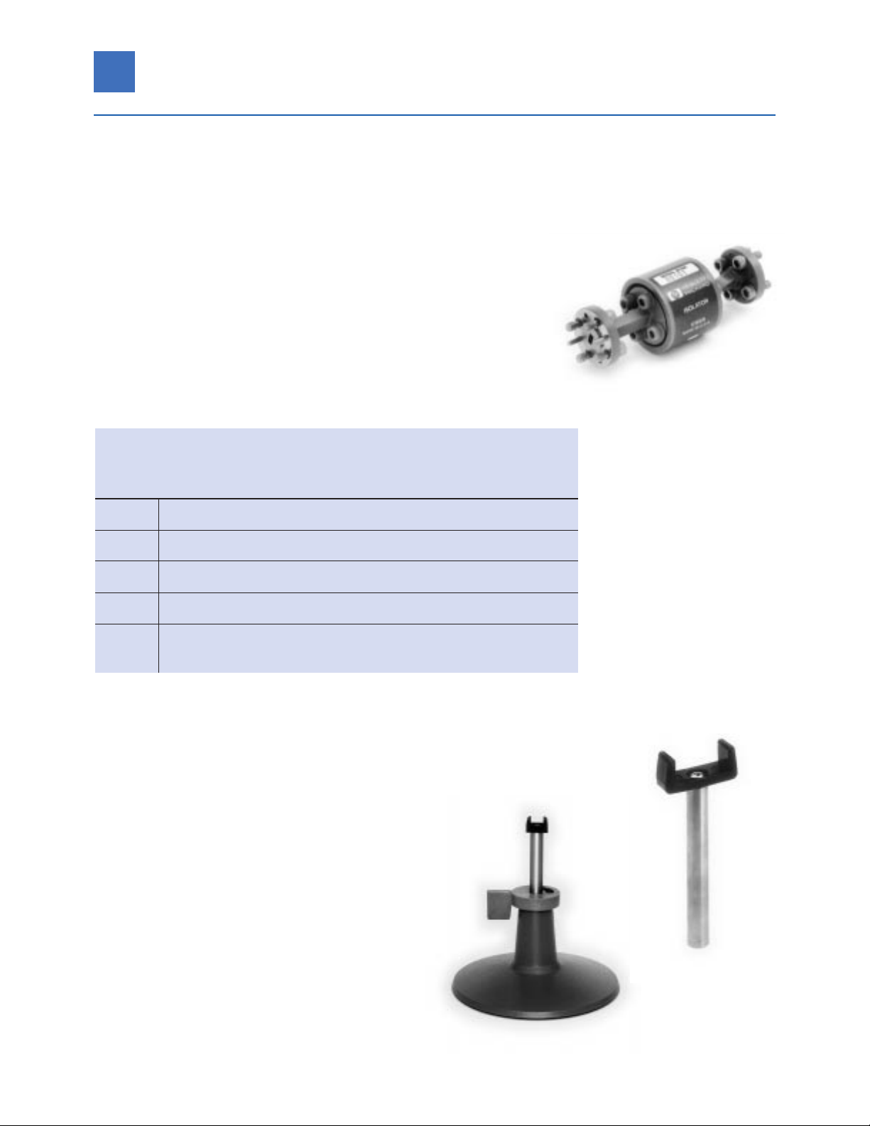
HP 365A Series
These products are ideal isolators for test and measurement applications.
Their high, broadband isolation (better than 25 dB) minimizes the
reflection effects of a source. Their low SWR and low insertion loss help
to improve accuracy without the attenuation of matching pads.
The HP 365A isolators use a Faraday-rotation design. It consists of a
waveguide section that contains low-loss ferrite material and impedance
matching elements. A permanent magnet supplies the external magnetic
bias field to the ferrite core.
Maximum Minimum Waveguide1Flange
1
Frequency Insertion Minimum Input Designator Designator
HP Range Max. Loss Isolation Power EIA UG-( )/U
Model (GHz) SWR (dB) (dB) (avg) MIL-W-85/( ) MIL-F-3922/( )
R365A 26.5 to 40 1.4 1.5 25 1.5 W WR-28 599
3-006 54C-003
Q365A 33 to 50 1.4 1.6 25 1.5 W WR-22 383
3-010 67B-006
U365A 40 to 60 1.4 1.8 25 1.5 W WR-19 383 (mod)
` 3-014 67B-007
V365A 50 to 75 1.5 2.0 25 1 W WR-15 385
3-017 67B-008
W365A 75 to 110 1.5 2.5 25 1 W WR-10 387 (mod)
3-023 67B-010
Specifications
1
The Waveguide/Flange Designator is provided to determine interface dimensions and generic material of HP products.
HP V365A
HP 11545A
HP 11540A Waveguide Stand
HP 11545/546/547/548A Waveguide Holders
The HP 11540A waveguide stand locks HP
waveguide holders at any height from 70 to 133 mm
(2.75 in to 5.25 in). The stand is 64 mm (2.5 in) high,
and the base measures 121 mm (4.75 in) in diameter.
HP 11545/546/547/548A waveguide holders are offered in
four sizes to hold waveguide covering frequencies from 8.2
to 40 GHz. They consist of a molded plastic cradle with a
center rod, as follows: HP 11545A X-Band, 11546A P-Band,
11547A K-Band, 11548A R-Band.
HP 11540A Waveguide Stand Shipping Weight: 454 g (1 lb).
HP 11545A to 11548A Waveguide Holder Shipping
Weight: 220 g (8 oz).
HP 11540A
Isolators, Stand/Holders
182
Page 7
Terminations, Fixed and Sliding
HP 910 Series Fixed Terminations
HP 910 waveguide loads are designed for terminating
test systems operating at low average powers. The
loads are carefully designed to absorb virtually all
of the applied power and ensure a lower SWR. They
may be used wherever a matched load is required,
as in the measurements of reflection, discontinuities,
or obstacles in waveguide systems.
HP X914B Sliding Load
This sliding load consists of a movable, tapered, lowreflection load element mounted in a section of precision
waveguide. A plunger controls the position of the load,
and provides a controllable range of at least one-half
wavelength at the lowest waveguide frequency. This
movement permits the phase of the residual load
reflection to be reversed so that this reflection can be
separated from other small reflections in the waveguide
system. Sliding loads are often used in calibration
procedures.
1
The Waveguide/Flange Designator is provided to determine interface dimensions and generic material of HP products.
Waveguide1Flange
1
Frequency Designator Designator Shipping
HP Range Maximum Maximum EIA UG- ( )/U Length Weight
Model (GHz) SWR Power (avg) MIL-W-85/( ) MIL-F-3922/( ) mm (in) kg (lb)
X910B 8.2 to 12.4 1.015 1 W WR-90 39 168 0.9
1-077 54C-008 (6.6) (2)
P910A 12.4 to 18 1.02 1 W WR-62 419 111 0.45
1-089 70A-007 (4.4) (1)
R910A 26.5 to 40 1.025 1 W WR-28 599 60 0.2
3-006 54-003 (2.4) (0.5)
Q910A 33 to 50 1.03 1 W WR-22 383 71 0.2
3-013 67B-013 (2.8) (0.5)
U910A 40 to 60 1.04 1 W WR-19 383 (mod) 71 0.2
3-015 67B-007 (2.8) (0.5)
W910C 75 to 110 1.03 0.2 W WR-10 387 (mod) 56 0.013
3-024 67B-010 (2.2) (0.03)
X914B 8.2 to 12.4 1.01 1 W WR-90 39 257 0.9
(Load Element) 1-077 54C-008 (10.1) (2)
Specifications
HP P910A
HP X914B
183
18
Waveguide Accessories
Visit our web site http://www.hp.com/go/mta
Page 8

Waveguide Band Designator
1
Flange Designator
1
Frequency
Range Other Cover Choke
HP Band TE10mode EIA IEC British JAN MIL-W- Common MIL-F- JAN EIA MIL-F JAN EIA
Designation (GHz) WR-( ) R-( ) WG-( ) RG-( )/U 85/( ) Usage Materials13922 /( ) UG -( ) /U CMR -( ) 3922 /( ) UG-( )/U CPR-( )
S 2.6 to 3.95 284 32 10 75 1- 041 Alum Alloy 56B-002 584 284 61-001 585A 284
G 3.95 to 5.85 187 48 12 95 1- 053 C, H Alum Alloy 57B-001 407 187 62-001 406B 187
J 5.85 to 8.2 137 70 14 106 1-065 Xn, C, G Alum Alloy 55B-002 441 137 60-002 440B 137
H 7.05 to 10 112 84 15 51 1-073 Xb, W Copper Alloy 54C-005 51 112 59D-015 522B
68 1- 072 Alum Alloy 54C-006 138
—
59D-016 137B 112
X 8.2 to 12.4 90 100 16 52 1-079 Copper Alloy 54C-007 39 90 59D-013 40B
—
67 1-078 Alum Alloy 54C-008 135
—
59D-014 136B 90
M 10 to 15 75 120 17 346 1- 085 Copper Alloy 70A-004
—
75 59D-010
——
347 1-084 Alum Alloy 70A-005
——— — —
P 12.4 to 18 62 140 18 91 1-089 Ku, Y, U Copper Alloy 70A-007 419
—
59D-001 541A
—
349 1-091 Alum Alloy 70A-008
——
59D-002
——
N 15 to 22 51 180 19 353 1-096 Copper Alloy 70A-010
——
69D-004
——
351 1-098 Alum Alloy 70A-011
——
69D-005
——
K 18 to 26.5 42 220 20 53 1-102 Copper Alloy 54C-001 595
—
59D-003 596A
—
121 1-104 Alum Alloy 54C-002 597
—
59D-004 598A
—
R 26.5 to 40 28 320 22 96 3-007 V, Ka, U, Copper Alloy 54C-003 599
—
59D-005 600A
—
—
3-009 A Alum Alloy
——————
Q 33 to 50 22 400 23 272 3 -011 Copper Alloy 67B-006 383
—— — —
—
3-013 Alum Alloy 67B-013
——— — —
U 40 to 60 19 500 24 358 3-015 Copper Alloy 67B-007 383 (mod)
—— — —
——
Alum Alloy
——————
V 50 to 75 15 620 25 273 3-018 M Copper Alloy 67B-002 385
—— — —
——
Alum Alloy
——————
W 75 to 110 10 900 27 359 3-024 Copper Alloy 67B-010 387 (mod)
—— — —
——
Alum Alloy
——————
1
The Waveguide/Flange Designator is provided to determine interface dimensions and generic material of HP products.
Abbreviations
EI A – Electronic Industries Association
IE C – International Electrotechnical Commission
JAN – Joint Army Navy
HP Waveguide Products Data
184
Waveguide Accessories
Page 9

Waveguide Dimensions
Theoretical Theoretical
Theoretical Peak Power CW Power
Inside Dimensions Outside Dimensions Attenuation Rating- Rating-
Nom. Wall Cutoff Low to High Low to High Low to High
HP Band Width Height Tol ± Width Height Tol ± Thickness Frequency Frequency Frequency Frequency
Designation mm (in) mm (in) mm(in) mm (in) mm (in) mm(in) mm (in) (GHz) (dB/100 ft) megawatts (kw) kilowatts (watts)
S 72.14 34.04 0.15 76.20 38.10 0.15 2.03 2.08 0.950 - 0.651 7.645 - 10.85 13.42 - 19.59
(2.84) (1.34) (0.006) (3.0) (1.5) (0.006 (0.08)
G 47.55 22.15 0.13 50.80 25.40 0.13 1.63 3.155 1.785 - 1.238 3.296 - 4.69 5.165 - 7.446
(1.872) (0.872) (0.005) (2.0) (1.0) (0.005) (0.064)
J 34.85 15.80 0.10 38.10 19.05 0.10 1.63 4.285 3.532-1.999 1.975 - 2.53 2.076 - 3.667
(1.372) (0.622) (0.004) (1.5) (0.75) (0.004) (0.064)
H 28.50 12.62 0.10 31.75 15.88 0.10 1.63 5.260 4.114 - 3.197 1.284 - 1.702 1.607 - 2.067
(1.122) (0.497) (0.004) (1.250) (0.625) (0.004) (0.064) 5.260 4.166 - 3.238 1.284 - 1.702 1.523 - 1.958
X 22.86 10.16 0.10 25.40 12.70 0.10 1.27 6.560 6.424 - 4.445 0.758 - 1.124 0.8621 - 1.246
(0.900) (0.40) (0.004) (1.0) (0.5) (0.004) (0.05) 6.560 6.506 - 4.502 0.758 - 1.124 0.8169 - 1.180
M 19.05 9.53 0.08 21.59 12.07 0.08 1.27 7.847 7.601 - 5.309 0.622 - 0.903 0.6621 - 0.9479
(0.75) (0.375) (0.003) (0.850) (0.475) (0.003) (0.05) 7.847 7.698 - 5.377 0.622 - 0.903 0.6273 - 0.8982
P 15.80 7.90 0.06 17.83 9.93 0.08 1.02 9.490 9.578 - 7.041 0.457 - 0.633 0.4513 - 0.6139
(0.622) (0.311) (0.0025) (0.702) (0.391) (0.003) (1.02) 9.490 9.700 - 7.131 0.457 - 0.633 0.4276 - 0.5816
N 12.95 6.48 0.06 14.99 8.51 0.08 1.02 11.54 13.08 - 9.477 0.312 - 0.433 0.2899 - 0.4000
(0.51) (0.255) (0.0025) (0.59) (0.335) (0.003) (0.04) 11.54 13.25 - 9.598 0.312 - 0.433 0.2746 - 0.3791
K 10.67 4.32 0.05 12.70 6.35 0.08 1.02 14.08 20.48 - 15.04 0.171 - 0.246 0.1565 - 0.2132
(0.42) (0.17) (0.002) (0.5) (0.25) (0.003) (0.04) 14.08 20.74 - 15.23 0.171 - 0.246 0.1483 - 0.2020
R 7.11 3.56 0.04 9.14 5.59 0.05 1.02 21.10 23.02 - 15.77 (96.0 - 146) (109.7 - 160.1)
(0.280) (0.14) (0.0015) (0.36) (0.22) (0.002) (0.04) 21.10 34.46 - 23.59 (96.0 - 146) (73.27 - 107.0)
Q 5.69 2.84 0.03 7.72 4.88 0.05 1.02 26.35 32.44 - 22.05 (64.4 - 97.0) (68.89 - 101.4)
(0.224) (0.112) (0.001) (0.304) (0.192) (0.002) (0.04) 26.35 48.53 - 32.99 (64.4 - 97.0) (46.05 - 67.74)
U 4.78 2.39 0.03 6.81 4.42 0.05 1.02 30.69 39.81 - 28.60 (48.0 - 70.0) (51.32 - 71.43)
(0.188) (0.094) (0.001) (0.268) (0.174) (0.002) (0.04) 30.69 — (48.0 - 70.0) —
V 3.76 1.88 0.03 5.79 3.91 0.05 1.02 39.90 60.25 - 41.17 (30.0 - 40.0) (30.27 - 44.30)
(0.148) (0.074) (0.001) (0.228) (0.154) (0.002) (0.04) 39.90 — (30.0 - 40.0) —
W 2.54 1.27 0.03 4.57 3.30 0.05 1.02 58.85 105.6 - 74.26 (14.0 - 20.0) (14.73 - 20.86)
(0.100) (0.05) (0.001) (0.18) (0.13) (0.002) (0.04) 58.85 — (14.0 - 20.0) —
185
18
Waveguide Accessories
Visit our web site http://www.hp.com/go/mta
Waveguide Accessories
Page 10

Waveguide Designator Flange Designator
Dimensions mm (in)
Frequency Material
HP Range MIL-W- B: Copper Alloy JAN MIL-F- Hole
Band (GHz) EIA 85/( ) A: AIum. Alloy UG-( )/U 3922/( ) A B C Diameter
H 7.05
to
10 WR-112 1-073 B 51 54C-005 17.2 18.7 47.6 4.3
1-072 A 138 54C-006 (0.676) (0.737) (1.875) (0.169)
X 8.2
to
12.4 WR-90 1-079 B 39 54C-007 15.5 16.3 41.3 4.3
1-078 A 135 54C-008 (0.61) (0.64) (1.625) (0.169)
M 10
to
15 WR-75 1-085 B — 70A-004 13.2 14.2 38.1 3.6
1-084 A — 70A-005 (0.52) (0.561) (1.50) (0.14)
P 12.4
to
18 WR-62 1-089 B 419 70A-007 12.6 12.1 33.5 3.7
1-091 A — 70A-008 (0.497) (0.478) (1.32) (0.144)
N 15
to
22 WR-51 1-096 B — 70A-010 10.3 11.3 30.1 3.6
1-098 A — 70A-011 (0.405) (0.443) (1.187) (0.14)
K 18
to
26.5 WR-42 1-102 B 595 54C-001 8.1 8.5 22.2 2.9
1-104 A 597 54C-002 (0.32) (0.335) (0.875) (0.116)
R 26.5
to
40 WR-28 3-007 B 599 54-003 6.4 6.7 19.1 2.9
3-009 A — — (0.25) (0.265) (0.75) (0.116)
H
M
N
Q
V
W
R U
X
P K
S
J
G
110 GHz
75.0 60.0
50.0
40.0
33.0 26.5
22.0
18.0
15.0
12.4 10.0
8.2
7.05
5.85 3.95
2.6
X
K
u
B
K
a
Microwave
Spectrum
(waveguide)
Electronic
Warfare
Bands
and Industry
Designations
HP
60
100 MHz
40
20 10 8 6 4 3
1 GHz
500 250
100 MHz
2
Microwave
Spectrum
(coax)
A
B C D
E
F
G H
I J
K
L
M
2
4 8
12 18 26 40
50 GHz
K K
K
X
C
S
u
a
L
Frequency
Spectrum
RF
Microwave
3
30
300 3000 MHz
30
300 GHz
EHF
SHF UHF
VHF
HF
A
A
C
B
B
Hole
Diameter
Rectangular Flanges
C
Frequency Band Data
HP Flange Data (7.05 to 40.0 GHz)
1
1
See Figure 1.
Figure 1. Rectangular Flanges
H, X, M, P, N, K, R Bands
186
Visit our web site http://www.hp.com/go/mta
Waveguide Accessories
Page 11

HP Frequency
Waveguide Designator Flange Designator
Band Range (GHz) EIA MIL-W-85/( ) Material MIL-F-3922/( ) JAN UG-( )/U
S 2.60 to 3.95 WR-284 1-041 Alum. Alloy 56B-002 584
G 3.95 to 5.85 WR-187 1-053 Alum. Alloy 57B-001 407
J 5.85 to 8.20 WR-137 1-065 Alum. Alloy 55B-002 441
Waveguide Designator Flange Designator
Frequency Material
Dimensions mm (in)
HP Range MlL-W- B: Copper Alloy MlL-F JAN
Band (GHz) EIA 85/( ) A: Alum. Alloy 3922/( ) UG-( )/U A B C Diameter D Diameter
K 18 to 26.5 WR-42 1-102 B 67B-004 425 10.7 4.3 28.6 23.8
1-104 A 67B-011 — (0.42) (0.17) (1.125) (0.9375)
R 26.5 to 40 WR-28 3-007 B 67B-005 381 7.1 3.6 28.6 23.8
3-009 A 67B-012 — (0.28) (0.14) (1.125) (0.9375)
Q 33 to 50 WR-22 3-011 B 67B-006 383 5.7 2.8 28.6 23.8
3-013 A 67B-013 — (0.224) (0.112) (1.125) (0.9375)
U 40 to 60 WR-19 3-015 B 67B-007 383 (mod) 4.8 2.4 28.6 23.8
— A — — (0.188) (0.094) (1.125) (0.9375)
V 50 to 75 WR-15 3-018 B 67B-002 385 3.8 1.9 19.1 14.3
— A — — (0.148) (0.074) (0.75) (0.5625)
W 75 to 110 WR-10 3-024 B 67B-010 387 (mod) 2.5 1.3 19.1 14.3
— A — — (0.10) (0.050) (0.75) (0.5625)
2
See Figure 3.
Figure 3.
K, R, Q, U,
V, W Bands
HP Precision Circular Flange Data (18.0 to 110.0 GHz)
2
HP Circular Flange Data (2.6 to 8.2 GHz)
1
1
See Figures 2a, 2b, and 2c.
22.5°
22.5°
Hole
Diameter
0.281
4.750
Diameter
S Band
J Band
2.750
Diameter
Hole
Diameter
0.218 ± 0.005
Hole
Diameter
0.219
C
Alignment Holes
0.063 ±0.001 Diameter Thru
Alignment Pins
0.062 ±0.001 Diameter Thru
0.296 Long, 2 Required
#4-40 NC –2B C Bore
0.140 Diameter x .034 ±0.001 Deep
4 Holes Equally Spaced
A
D
B
3.250
Diameter
G Band
Figure 2a.
Figure 2b. Figure 2c.
187
18
Waveguide Accessories
Waveguide Accessories
 Loading...