

Page 1

HP 8935 CDMA Cellular/PCS Base Station Test Set
Main Menu
Programmer’s Guide
Firmware Version: A.01.00 and above
HP Part N u mber E6380-90018
Revision A
Printed in U.S.A.
November 1997
PRELIMINARY
This document, part number E6380-90018, is a preliminary manual.
Updates will be a vaila ble six mo nths fr om the date of this manual. If you woul d like a n updated versio n when it
becomes availa ble, please send us the fo llo wi ng info rmation:
Name________________________ _______________________________________________JobTitle _______________________
Company___ ____________________ ___________ A d dr e ss_________ ____________________________________
Phone____ ___________ _______________________E-mail_ ______________________________________________ __________
This document is on (circle one): CD-ROM Paper
E-Mail: [email protected]
Fax: HP 8935 Updates, Karen Otto, 509-921-3700
Snail Mail: HP 8935 Updates, Karen Otto, Hewlett-Packard Company, 24001E. Mission Avenue, Liberty La,
WA, 99019
© Copyright 1997 Hewlett-Packard Company
Page 2

Notice
Main Menu
Information contained in this document is subject to change without
notice.
All Rights Reserved. Reproduction, adaptation, or translation without
prior written permission is prohibited, except as allowed under the
copyright laws.
This material may be reproduced by or for the U.S. Government
pursuant to the Copyright License under the clause at DFARS
52.227-7013 (APR 1988).
2
Page 3

Manufacturer’s Declaratio n
Main Menu
This statement is provided to comply with the requirements of the
German Sound Emission Directive, from 18 January 1991.
This product has a sound pressure emiss ion (a t the op er ato r posit ion) <
70 dB(A).
Sound Pressure Lp < 70 dB(A).
At Operator Position.
Normal Operation.
Accordi n g t o ISO 7779:19 88/EN 277 79:1991 (T ype Test).
Herstellerbescheinigung
Diese Information steht i m Zusammenhang mit den Anf orderungen der
Maschinenlärminformationsverordnung vom 18 Januar 1991.
Schalldruckpegel Lp < 70 dB(A).
Am Arbeitsplatz.
Normaler Betrieb.
Nach ISO 7779:198 8/ E N 27779:19 91 (Typprü fu n g).
3
Page 4

Safety
!
Main Menu
GENERAL
This product and related documentation must be reviewed for
familiarization with safety markings and instructions before operation.
This product has been designed and tested in accordance with IEC
Publication 1010, "Safety Requirements for Electronic Measuring
Apparatus," and has been supplied in a safe condition. This instruction
documentation contains information and warnings which must be
followed by the user to ensure safe operation and to maintain the
product in a safe condition.
SAFETY SYMBOLS
Indicates instrument damage can occur i f indic ated operat ing limits a re
exceeded. Refer to the instructions in this guide.
Indicates hazardous voltages.
Indicates earth (ground) terminal
WARNING A WARNING note denotes a hazard. It calls attention to a
procedure, practice, or the like, which, if not correctly
performed or adhered to, coul d result in personal inj ury. Do not
proceed beyond a WARNING sign until the indicated conditions
are fully understood and met.
CAUTION A CAUTION note denotes a hazard. It calls attention to an operation
procedure, practice, or the like, which, if not correctly performed or
adhered to, could result in damage to or destruction of part or all of the
product. Do not proceed beyond an CAUTION note until the indicated
conditions are fully understood and met.
Safety Considerations for this Instrument
4
Page 5

WARNING This product is a Safety Class I instrument (provided with a
Main Menu
protective earthing ground incorporated in the power cord) .
!
The mains plug shall only be inserted in a socket outlet
provided with a protective earth contact. Any interruption of
the protective conductor inside or outside of the product is
likely to make the product dangerous. Intentional interruption
is prohibited.
Do not expose to or operate this instrument in outdoor
!
atmospheric conditions such as direct rain, hail, sleet, snow,
icing, sunshine or wind. Operate this instrument only within its
specified temp erature humidity co nditions.
This instrument is equipped with internal ground fault circuit
!
interrupter class A.
• This device does not protect against electrical shock due to
contact with both circuit conductors or a fault in supply
wiring to product.
• Do not use extension cord to connect this product to power
receptacle. Attention-ne pas utiliser de rallong e pour
raccorder le detecteur-disjoncteur a la prise de courant.
• Replace cordset only with HP 8120 series. Attention Remplacer uniquement par un cordon amovible numer o
8120.
• Do not use in wet location. Ne pas utiliser dans un
emplacement mouille.
WARNING Whenever it is likely that the protection has been impaired, the
instrument must be made inoperative and be secured against
any unintended operation.
If this instrument is to be energized via an autotransformer (for
voltage reduction), make sure the common terminal is
connected to the earth terminal of the power source.
If this product is not used as specified, the protection provided
by the equipment could be impaired. This product must be used
in a normal condition (in which all means for protection are
intact) only.
No operator serviceable parts in this product. Refer servicing to
qualified personnel. To prevent electrical shock, do not remove
covers.
Servicing inst ructions are for use by qualified personnel only.
To avoid electrical shock, do not perform any servicing unless
you are qualified to do so.
5
Page 6

The opening of covers or removal of parts is likely to expose
Main Menu
dangerous voltages. Disconnect the product from all voltage
sources while it is being opened.
Adjustments described in the manual ar e performed with
power supplied to the instrument while protective covers are
removed. Energy available at many points may, if contacted,
result in personal injury.
The power cord is connected to internal capacitors that my
remain live for 5 seconds after disconnecting the plug from its
power supply.
For Continued protection against fire hazard, replace the line
fuse(s) only with 250 V fuse(s) or the same current rating and
type (for example, normal blow or time delay). Do not use
repaired fuses or short circuited fuseholders. FUSE: T 5.0A
CAUTION Always use the three-prong ac power cord supplied with this product.
Failure to ensure adequate earth grounding by not using this cord may
cause personal injury and/or product damage.
This product is designed for use in Installation Category II and
Pollution Degree 2 per IEC 1010 and IEC 664 respectively. For indoor
use only.
This product has autoranging line voltage input, be sure the supply
voltage is within the specified range.
Ventilation Requirements: When installing the product in a cabinet,
the convection into and out of the product must not be restricted. The
ambient temperature (outside the cabinet) must be less than the
maximum operating temperature of the product by 4° C for every 100
watts dissipated in the cabinet. If the total power dissipated in the
cabinet is greater than 800 watts, then forced convection must be used.
To prevent electrical shock, disconnect instrument from mains (line)
before cleaning. Use a dry cl oth or one s lightl y da mpened wi th water to
clean the external case parts. Do not attempt to clean internally.
6
Page 7

Product Markings
Main Menu
CE - the CE mark is a registered trademark of the European
Community. A CE mark accompanied by a year indicated the year the
desi gn was pro ven.
CSA - the CSA mark is a registered trademark of the Canadian
Standards Associat io n .
CERTIF ICATION
Hewlett-Packard Company certif ies tha t thi s produc t met its publ i shed
specifications at the time of shipment from the factory.
Hewlett-Packard further certifies that its calibration measurements
are traceable to the United States National Institute of Standards and
Technology, to the extent allowed by the Institute’s calibration facility,
and to the calibration facilities of other International Standards
Organization members.
7
Page 8

Warranty
Main Menu
This Hewlett-Packard instrume nt produc t i s warr anted a gainst d ef ec ts
in material and workmanship for a period of one year from date of
shipment. During the warranty period, Hewlett- Packard Company will
at its option, either repair or replace products which prove to be
defective.
For warranty service or repair, this product must be returned to a
service facility designated by HP. Buyer shall prepay shipping charges
to HP and HP shall pay s hipping cha rges, duti es, and taxes for product s
returned to HP from another country.
HP warrants that its software and firmware designated by HP for use
with an instrument will execute its programming instructions when
properly installed on that instrument. HP does not warrant that the
operation of the instrument, or software, or firmware will be
uninterrupted or error free.
LIMITATION OF WARRANTY
The foreg o in g warranty sh all not appl y t o de fe ct s re su lting from
improper or inadequate maintenance by Buyer, Buyer-supplied
software or inte rfa cing, una uthor ized modification or mi suse, op er ation
outside of the enviro nmental sp ec ifications for the pro duct, or improper
site preparation or maintenance.
NO OTHER WARRANTY IS EXPRESSED OR IMPLIED. HP
SPECIFICALLY DISCLAIMS THE IMPLIED WARRANTIES OF
MERCHANTABILITY AND FITNESS FOR A PARTICULAR
PURPOSE.
EXCLUSI VE REMED IE S
THE REMEDIES PROVIDED HEREIN ARE BUYER’S SOLE AND
EXCLUSIVE REMEDIES. HP SHALL NOT BE LIABLE FOR ANY
DIRECT, INDIRECT, SPECIAL, INCIDENTAL, OR
CONSEQUENTIAL DAMAGES, WHETHER BASE ON CONTRACT,
TORT, OR ANY OTHER LEGAL THEORY.
8
Page 9

ASSISTANCE
Main Menu
Main te na n c e A gr e e m en ts
Product maintenance agreements and other customer assistance
agreements are available for Hewlett-Packard products. For any
assistance, contact your nearest Hewlett-Packard Sales and Service
Office.
9
Page 10

Regional Sales Offices
Main Menu
IMPORTANT Regional Sales an d Se rv ic e Offices
Eastern USA
Sales Office
Hewlett-Packard Company
2101 Gather Rd.
Rockville, MD 20850
Tel: (301) 258-2000
Southern USA
Sales and Service
Hewlett-Packard Company
1995 North Park Place
Atlanta, GA 30339
Sales
Tel: (404) 955-1500
Fax: (404) 980-7292
Service
Tel: (404) 850-2544
Fax: (404) 980-7292
Western USA
Sales and Service
Hewlett-Packard Company
24 Inverness Place East
Englewood, CO 80112
Sales
Tel: (303) 649-5000
Fax: (303) 649-5787
Service
Tel: (303) 649-5512
Fax: (303) 649-5787
Eastern USA
Sales Office
Hewlett-Packard Company
2101 Gather Rd.
Rockville, MD 20850
Tel: (301) 258-2000
Southern USA
Service Center
Hewlett-Packard Company
930 E. Campbell Road
Richardson, TX 75081
Tel: (214) 699-4331
Western USA
Sales an d S e r vice
Hewlett-Packard Company
1421 South Manhattan Avenue
Fullerton, CA 92631
Sales
Tel: (714) 999-6700
Fax: (714) 778-3033
Service
Tel: (714) 758-5490
Fax: (714) 778-3033
Midwestern USA
Sales and Service
Hewlett-Packard Company
5201 Tollview Drive
Rolling Meadows, IL 60008
Tel: (708) 342-2000
Western US A
Service Center
Hewlett-Packard Company
301 E. Evelyn Avenue
Mountain View, CA 94041
Tel: (415) 694-2000
Fax: (415) 694-0601
United States of America
Customer I nformation Center
Hewlett-Packard Company
Tel: (800) 752-0900
6:00 am to 5:00 pm Pacific Tim e
Parts Direct: 1-800-227-8164
South Eastern Europe
Sales and Service
Hewlett-Packard Ges. m.b.h.
Liebigasse 1
P.O. Box 72
A-1222 Vienna, Austria
Telephone: 43 222 2500 0
Telex: 13 4425
10
European Multicountry Region
Sales an d S e r vice
Hewlett-Packard S.A.
P.O. Box 95
150, Route dv Nant_dl_AVRIL
CH-1217 Meyrin 2
Geneva, Switzerland
Telephone: (41/2 2) 780-8111
Fax: (41/22) 780-8542
North e rn Euro pe
Sales and Service
Hewlet t- P a cka r d Ne de rland B. V .
Startbaan 16
1187 XR
Amstelveen, The Netherlands
P.O. Box 667
Telephone: 31/ 20 5476911 X 6631
Fax: 31-20-6471825NL
Page 11

Asia
Main Menu
Sales an d S e r vice
Hewlett-Packard Asia Ltd.
22-30/F Peregrine Tower
Lippo Center
89 Queensway, Central
Hong Kong
G.P.O. Box 863 Hong Kong
Telephone: 852-848-7777
Fax: 852-868-4997
Japan
Sales and Service
Yokogawa-Hewlett-Packard Ltd.
3-29-21, Takaido-Higashi
Suginami-Ku, Tokyo 168
Telephone: 81 3 3331-6111
Fax: 81 3 3331-6631
International Sales Branch
Headquarter s
Sales and Service
Hewlett-Packard S.A.
39 Rue Veyrot
P.O. Box 365
1217 Meyrin 1
Geneva, Switzerland
Telephone: 41-22-780-4111
Fax: 41-22-780-4770
Australi a , Ne w Zea l a nd
Sales an d S e r vice
Hewlett-Packard Ltd.
P.O. Box 221
31-41 Joseph Stre et
Blackburn, Victoria 3130
Telephone: (61/ 3) 895-2895
Fax: (61/3) 898-9257
Canada
Service Center
Hewlett-Packard Ltd.
11120 178 Street
Edmonton, Alberta T5S 1P2
Canada
Telephone: (403) 486-6666
Fax: (403) 489-8764
Canada
Sales and Service
Hewlett-Pac ka rd (Canada) Ltd.
5150 Spectrum Way
Mississauga, Ontario L4W 5G1
Canada
Telephone: (416) 206-4725
Fax: (416) 206-4739
Latin America
Hewlett-Packard Company
LAHQ Mexico City
Col. Lomas de Virreyes
11000 Mexico D.F.
Mexico
Telephone: (52/ 5) 326-4000
Fax: (52/5) 202 7718
Canada
Service Center
Hewlett-Packard Company
17500 Transcanada Highway
S. Serv Road
Kirkland, Quebec H9J 2X 8
Canada
Telephone: (416) 206-3295
United Kingdo m
Sales and Service
Hewlett-Packard Ltd.
Cain Road
Amen Corner
Bracknell, Berkshire
RG12 1HN
United Kingdo m
Telephone: 44 344 360000
11
Page 12

12
Main Menu
Page 13

Contents
Main Menu
In This Manual. . . . . . . . . . . . . . . . . . . . . . . . . . . . . . . . . . . . . . . . . . . . 15
1. Using HP-IB
Overview of the Test Set . . . . . . . . . . . . . . . . . . . . . . . . . . . . . . . . . . . . 18
Getting Started . . . . . . . . . . . . . . . . . . . . . . . . . . . . . . . . . . . . . . . . . . . 25
Remote Operation . . . . . . . . . . . . . . . . . . . . . . . . . . . . . . . . . . . . . . . . . 35
Addressing . . . . . . . . . . . . . . . . . . . . . . . . . . . . . . . . . . . . . . . . . . . . . . . 37
IEEE 488.1 Remote Interface Message Capabilities . . . . . . . . . . . . . . 38
Remote/Local Modes . . . . . . . . . . . . . . . . . . . . . . . . . . . . . . . . . . . . . . . 44
2. Method s Fo r Read i ng Me asu r eme n t Re sults
Background . . . . . . . . . . . . . . . . . . . . . . . . . . . . . . . . . . . . . . . . . . . . . . 48
HP BASIC ‘ON TIMEOUT’ Example Program . . . . . . . . . . . . . . . . . . 50
HP BASIC ‘MAV’ Example Program . . . . . . . . . . . . . . . . . . . . . . . . . . 54
3. HP-IB Command Guidelines
Sequential and Overlapped Commands. . . . . . . . . . . . . . . . . . . . . . . . 60
Guidelines for Operation. . . . . . . . . . . . . . . . . . . . . . . . . . . . . . . . . . . . 61
5. HP-IB Command Dictionary
Notice . . . . . . . . . . . . . . . . . . . . . . . . . . . . . . . . . . . . . . . . . . . . . . . . . . . 96
Using This Dictionary . . . . . . . . . . . . . . . . . . . . . . . . . . . . . . . . . . . . . . 97
:AFANalyzer subsystem . . . . . . . . . . . . . . . . . . . . . . . . . . . . . . . . . . . . 98
:AFG1 | AFGENERATOR1 subsystem . . . . . . . . . . . . . . . . . . . . . . . 106
:AFG2 | AFGENERATOR2 subsystem . . . . . . . . . . . . . . . . . . . . . . . 108
:CANalyzer subsystem. . . . . . . . . . . . . . . . . . . . . . . . . . . . . . . . . . . . . 110
:CBUFfer subsystem . . . . . . . . . . . . . . . . . . . . . . . . . . . . . . . . . . . . . . 120
:CCOMmon subsystem . . . . . . . . . . . . . . . . . . . . . . . . . . . . . . . . . . . . 123
:CDANaly ze r subsystem . . . . . . . . . . . . . . . . . . . . . . . . . . . . . . . . . . . 124
:CGENerator subsystem . . . . . . . . . . . . . . . . . . . . . . . . . . . . . . . . . . . 132
:CONFigu re subsystem . . . . . . . . . . . . . . . . . . . . . . . . . . . . . . . . . . . . 135
:DISPlay subsystem. . . . . . . . . . . . . . . . . . . . . . . . . . . . . . . . . . . . . . . 159
Integer Number Setting Syntax . . . . . . . . . . . . . . . . . . . . . . . . . . . . . 161
:MEASure subsystem . . . . . . . . . . . . . . . . . . . . . . . . . . . . . . . . . . . . . 162
Multiple Real Number Setting Syntax . . . . . . . . . . . . . . . . . . . . . . . . 186
Number Measurement Syntax . . . . . . . . . . . . . . . . . . . . . . . . . . . . . . 187
:OSCilloscope subsystem. . . . . . . . . . . . . . . . . . . . . . . . . . . . . . . . . . . 190
:PROGram subsystem . . . . . . . . . . . . . . . . . . . . . . . . . . . . . . . . . . . . . 201
Real Number Setting Syntax . . . . . . . . . . . . . . . . . . . . . . . . . . . . . . . 203
[:REGister] subsystem. . . . . . . . . . . . . . . . . . . . . . . . . . . . . . . . . . . . . 205
:RFANalyzer subsystem . . . . . . . . . . . . . . . . . . . . . . . . . . . . . . . . . . . 208
:RFGenerator subsystem. . . . . . . . . . . . . . . . . . . . . . . . . . . . . . . . . . . 212
:SANalyzer subsystem. . . . . . . . . . . . . . . . . . . . . . . . . . . . . . . . . . . . . 216
:STATus . . . . . . . . . . . . . . . . . . . . . . . . . . . . . . . . . . . . . . . . . . . . . . . . 225
:SYSTem. . . . . . . . . . . . . . . . . . . . . . . . . . . . . . . . . . . . . . . . . . . . . . . . 234
:TESTs Subsystem. . . . . . . . . . . . . . . . . . . . . . . . . . . . . . . . . . . . . . . . 235
:TRIGger subsystem . . . . . . . . . . . . . . . . . . . . . . . . . . . . . . . . . . . . . . 241
11
Page 14

Contents
Main Menu
6. IEEE Common Commands
IEEE 488.2 Common Commands . . . . . . . . . . . . . . . . . . . . . . . . . . . . 244
Common Command Descriptions . . . . . . . . . . . . . . . . . . . . . . . . . . . . 245
7. Triggering Measurements
Triggering Measurements. . . . . . . . . . . . . . . . . . . . . . . . . . . . . . . . . . 256
8. Advanced Ope r ations
Increasing Measurement Throughput . . . . . . . . . . . . . . . . . . . . . . . . 264
Status Reporting . . . . . . . . . . . . . . . . . . . . . . . . . . . . . . . . . . . . . . . . . 270
HP-IB Service Requests . . . . . . . . . . . . . . . . . . . . . . . . . . . . . . . . . . . 317
Instrument Initialization . . . . . . . . . . . . . . . . . . . . . . . . . . . . . . . . . . 326
Passing Control . . . . . . . . . . . . . . . . . . . . . . . . . . . . . . . . . . . . . . . . . . 337
9. Memory Cards/Mass Storage
Default File System. . . . . . . . . . . . . . . . . . . . . . . . . . . . . . . . . . . . . . . 346
Mass Storage Device Overview. . . . . . . . . . . . . . . . . . . . . . . . . . . . . . 347
Default Mass Storage Locations. . . . . . . . . . . . . . . . . . . . . . . . . . . . . 352
Mass Storage Access . . . . . . . . . . . . . . . . . . . . . . . . . . . . . . . . . . . . . . 354
DOS and LIF File System Considerations. . . . . . . . . . . . . . . . . . . . . 355
Using the ROM Disk . . . . . . . . . . . . . . . . . . . . . . . . . . . . . . . . . . . . . . 361
Using Memory Cards. . . . . . . . . . . . . . . . . . . . . . . . . . . . . . . . . . . . . . 362
Backing Up Procedure and Library Files . . . . . . . . . . . . . . . . . . . . . . 367
Copying Files Using IBASIC Commands. . . . . . . . . . . . . . . . . . . . . . 368
Using RAM Disk . . . . . . . . . . . . . . . . . . . . . . . . . . . . . . . . . . . . . . . . . 370
10. IBASIC Controller
Introduction . . . . . . . . . . . . . . . . . . . . . . . . . . . . . . . . . . . . . . . . . . . . . 374
The IBASIC Controller Screen . . . . . . . . . . . . . . . . . . . . . . . . . . . . . . 375
Important Notes for Program Development. . . . . . . . . . . . . . . . . . . . 377
Program Development . . . . . . . . . . . . . . . . . . . . . . . . . . . . . . . . . . . . . 378
Interfacing to the IBASIC Controller using Serial Ports . . . . . . . . . 380
Choosing Your Development Method. . . . . . . . . . . . . . . . . . . . . . . . . 394
Method #1. Progr am De velo p men t on an E xter nal B ASI C L anguage
Computer . . . . . . . . . . . . . . . . . . . . . . . . . . . . . . . . . . . . . . . . . . . . . . . 396
Method #2. Developing Programs on the Test Set Using the IBASIC
EDIT Mode. . . . . . . . . . . . . . . . . . . . . . . . . . . . . . . . . . . . . . . . . . . . . . 403
Method #3. Developing Programs Using Word Processor on a PC
(Least Preferred) . . . . . . . . . . . . . . . . . . . . . . . . . . . . . . . . . . . . . . . . . 407
Uploading Programs from the Test Set to a PC. . . . . . . . . . . . . . . . . 415
Serial I/O from IBASIC Programs . . . . . . . . . . . . . . . . . . . . . . . . . . . 416
PROGram Subsystem . . . . . . . . . . . . . . . . . . . . . . . . . . . . . . . . . . . . . 419
The TESTS Subsystem . . . . . . . . . . . . . . . . . . . . . . . . . . . . . . . . . . . . 441
11. Erro r Mes sa ge s
General Information About Error Messages . . . . . . . . . . . . . . . . . . . 448
HP-IB Errors . . . . . . . . . . . . . . . . . . . . . . . . . . . . . . . . . . . . . . . . . . . . 454
Text Only HP-IB Errors . . . . . . . . . . . . . . . . . . . . . . . . . . . . . . . . . . . 455
12
Page 15

Contents
Main Menu
Numbered HP-IB Error Descriptions. . . . . . . . . . . . . . . . . . . . . . . . . 457
13
Page 16

Contents
Main Menu
14
Page 17

In This Manual
Main Menu
This manual explains how to use t he HP 8935 to manually te st a CDMA
Base Station.
What is Discussed This Manual
This document presents a step-by-step approach to CDMA base station
testing using the Test Set, including what you need to know before you
can start testing.
What is Not Discussed in this Manual
General operation of the Test Set , such as changing display screens
and their associated controls, is discussed in the Reference Guide
(HP part number E6380-900 19).
Detailed operation of the Test Set’s spectrum analyzer and oscilloscope.
Although there are basic explanations in this manual, more detail is
provided in the Reference Guide.
How to control your base station, switch system, or any other software
or hardware associated with your cell site equipment. Each
manufacturer and cellular service provider has their own cell site
control and base station configuration procedures that go beyond the
scope of this documentation.
How to perform IBASIC programming operations, such as writing,
editing, copying, or cataloguing programs. Programming the
Test Set is explained in the Programming Manual (HP part number
E6380-90018), and the IBASIC language is explained in the
HP Instrument BASIC User’s Handbook (HP part number
E2083-90005).
Conventions Used in This Manual
The following conventions are used throughout this manual to help
clarify instructions and reduce unnecessary text:
Test Set refers to the HP 8935.
Test Set keys are indicated like this:
Test Set screen information, such as a measurement result or an error
message, is shown like this: TX Channel Power -1.3 dBm
Preset
15
Page 18

Which Document is
Main Menu
Required?
Table 1 Document Navigation
Document Part Number Usage
The following documents ar e part of the HP 8935 document set. Use the
table to help you decide which document you need.
CDMA Application
Guide
AMPS Application Guide E6380-90017 Use this manual for makin g AMPS base stat ion
Reference Guide E6380-90019 Use this manual for screen and field descriptio ns
Programmer’s Guide E6380-90018 Use this manual to learn HP-IB syn tax and for
Assembly Level Repair
Guide
E6380-90016 Use this manual for basic CDMA m easure ments
and for getting started with the Test Set.
measurements.
and general operation information about the Test
Set.
learning ho w to program the Test Set.
E6380-90015 Use this manu al to perfor m calibra tion o n th e
Test Set and for gene r al serv ice info rmat io n.
16
Page 19

1 Using HP -I B
Main Menu
17
Page 20

Using HP-IB
Main Menu
Overview of the Test Set
Overview of the Test Set
The Test Set combines numerous separate test instruments and an
Instrument BASIC (IBASIC) Controller into one package. All of the
Test Set’s functions ca n be automati cally c ontrolled through a pplication
programs running on the built-in IBASIC Controller or on an external
controller connected through HP-IB.
Developing programs for the Test Set is simplified if the programmer
has a basic understanding of how the Test Set operates. An overvi ew of
the Test Set’s operation is best presented in terms of how information
flows through the unit. The simplified block diagrams shown in
1-1 on page 23
information and measurement result information ar e routed among the
Test Set’s instruments, instrument control hardware, built-in IBASIC
controller, and other components.
The Test Set has two operating modes: Manual Control mode and
Automatic Control mode. In Manual Control mode the Test Set’s
operation is controlled through the front panel keypad/rotary knob.
There are two Automatic Control modes: Internal and External. In
Internal Automatic Control mode the Test Set’s operation is controlled
by an application program running on the built-in IBASIC Controller.
In External Automatic Control mode the Test Set’s operation is
controlled by an external controller connected to the Test Set through
the HP-IB interface.
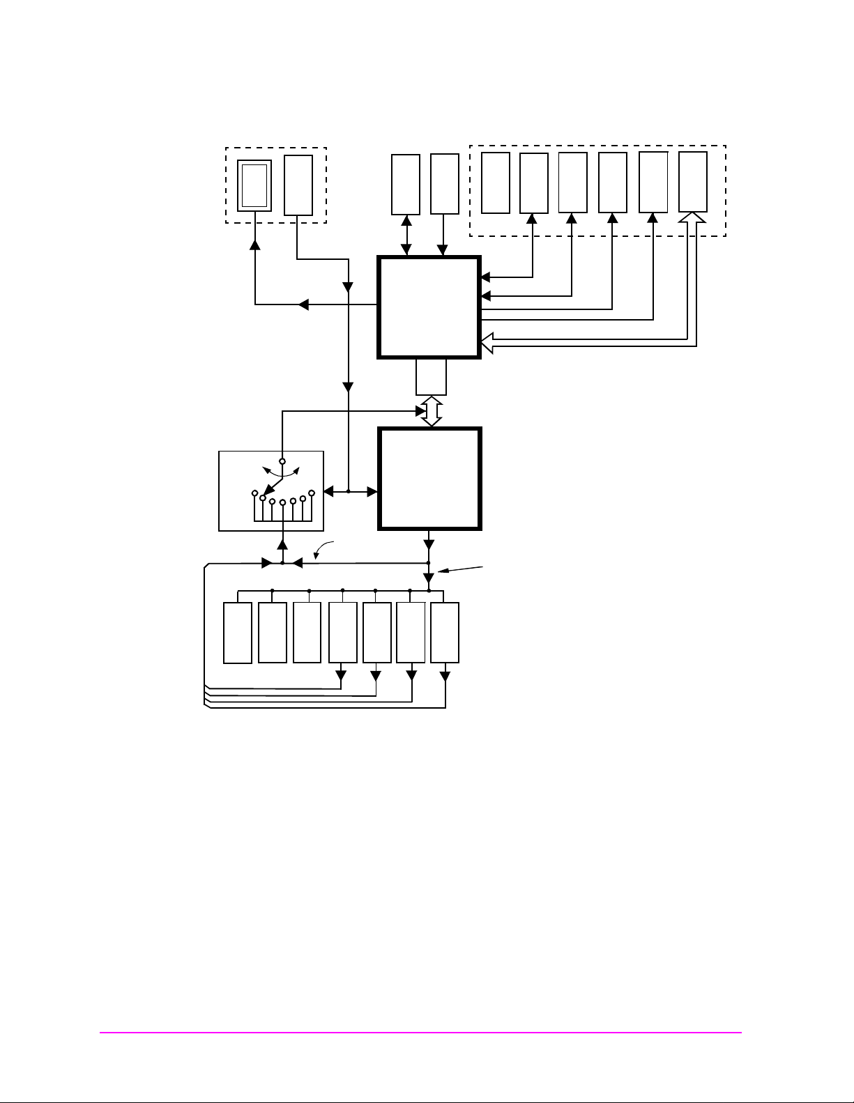
and figure 1-2 on page 24 depict how instrument control
figure
18 Chapter 1 PRELIMINARY
Page 21

Manual Control Mode
Main Menu
The Test Set’s primary instruments are shown on the left side of figure
. There are two classes of instruments in the Test Set: signal
1-1
analyzers (RF Analyzer, AF Analyzer, Oscilloscope, Spectrum
Analyzer) and signal sources (RF Generator, AF Generator #1, AF
Generator #2).
Since so many instruments are integrated into the Test Set, it is not
feasible to have an actual “front panel” for each instrument. Therefore,
each instrument’s front panel is maintained in firmware and is
displayed on the display whenever the instr ume nt is selected. Only one
instrument front panel can be displayed at any given time (up to four
measurement results can be displayed simultaneously if desired). Just
as with stand alone instruments, instrument front panels in the Test
Set can contain i nstrument setting i nformation, measurement re sult(s),
or data input from the DUT (Device Under Test).
Using the Test Set in Manual Control mode is analogous to using a set
of bench or rack-mounted test equipment. To obtain a measurement
result with a bench or racked system, the desired measurement must
be “active.” For example, if an RF power meter is in the bench or racked
system and the user wishes to measure the power of an RF carri er they
must turn the power meter on, and look at the front panel to see the
measurement result. Other instruments in the system may be turned
off but this would not prevent the operator from measuring the RF
power.
Using HP-IB
Overview of the Test Set
Conceptually, the same is true for the Test Set. In order to make a
measurement or input data from a DUT, the desir ed measurement fiel d
or data field must be “active.” This is done by using the front panel
keypad/rotary knob to select the instrument whose front panel contains
the desired measurement or data field and making sure that the
desired measurement or data field is turned ON.
Figure 1-1 shows that instrument selection is handled by the screen
control hardware which routes the selected instrument’s front panel to
the display. Once an instrument’s front panel is displayed on the
display, the user can manipulate the instrument settings, such as
turning a specific measurement or data field on or off, using the
keypad/rotary knob.
handled by the Instrument Control hardware which routes setup
information from the front panel to the individual instruments.
An HP-IB/RS-232/Parallel Printer interface is located in the Test Set.
In Manual Control mode this provides the capability of connecting an
external HP-IB, serial, or parallel p rinter to t he Test Set so tha t display
screens can be printed.
Figure 1-1 also shows that instrument setup is
Chapter 1 PRELIMINARY 19
Page 22

Using HP-IB
Main Menu
Overview of the Test Set
Internal Automati c Control Mode
In Internal Automatic Control mode the Test Set’s operation is
controlled by an application program running on the built-in
Instrument BASIC (IBASIC) Controller. The built-in controller runs
programs written in IBASIC, a subset of the Hewlett-Packard BASIC
programming language used on the HP 9000 Series 200/300 System
Controllers. IBASIC is the only programming language supported on
the built-in IBASIC Controller.
Similarities Between the Test Set’s IBASIC Controller and
Other Single-T asking C ontrollers
The architecture of the IBASIC Controller is similar to that of other
single-tasking instrumentation controllers. Only one program can be
run on the IBASIC Contr oller at any given time. The program is loaded
into RAM memory from some type of mass storage device. Four types of
mass storage devices are available to the Test Set: SRAM memory
cards, ROM memory cards connected to the HP-IB interface, internal
RAM disc, and internal ROM disc. Three types of interfaces are
available for connecting to external instruments and equipment:
HP-IB, RS-232, and 16-bit parallel.
Figure 1-2 shows how infor mation is routed inside the Test Set when it is
in Internal Automatic Control mode. In Manual Control mode certain
Test Set resources are dedicated to manual operation. These resources
are switched to the IBASIC Controller when an IBASIC program is
running. These include the serial interface ports at select codes 9, 10,
and 11, the HP-IB interface at select code 7, the parallel printer
interface ports at select codes 15 and 16, and the display. In Manual
Control mode, front panel information (instrument settings,
measurement results, dat a input from the DUT) is routed to the di splay
through the screen control hardware. In Internal Automatic Control
mode the measurement results and data input from the DUT are routed
to the IBASIC Controller through a dedicated HP-IB interface. Also, in
Internal Automatic Control mode, the display is dedicated to the
IBASIC Controller for program and graphics display. This means
instrument front panels cannot be displayed on the display when an
IBASIC program is running.
Differences Between the Test Set’s IBASIC Controller and
Other Single-T asking C ontrollers
The IBASIC Controller is unlike other single tasking instrumentation
controllers in several ways. First, it does not have a keyboard. This
imposes some limitations on creating and editing IBASIC programs
directly on the Test Set. In Internal Automatic Control mode a “virtual”
keyboard is available in firmware which allows the operator to enter
alphanumeric data into a dedicated input field using the rotary knob.
This is not the recommended programming mode for the IBASIC
Controller. This feature is provided to allow user access to IBASIC
20 Chapter 1 PRELIMINARY
Page 23

Using HP-IB
Main Menu
Overview of the Test Set
programs for short edits or troubleshooting. Several programming
modes for developing IBASIC programs to run on the internal IBASIC
Controller are discussed in this manual.
Secondly, the IBASIC Controller has a dedicated HP-IB interface,
select code 8 in
figure 1-2 , for communicating with the internal
instruments of the Test Set. This HP-IB interface is only available to
the IBASIC Controller. There is no external connector for this HP-IB
interface. No external instruments may be added to this HP-IB
interface. The HP -I B in t e rface, select co de 7 in figure 1-2 , is used to
interface the Test Set to external instruments or to an external
controller. The dedicated HP-IB interface at select code 8 conforms to
the IEEE 488.2 Standard in all respects but one. The difference being
that each instrument on the bus does not have a unique address. The
Instrument Control Hardware determines which instrument is being
addressed through the command syntax. Refer to
Command Dictionary"
for a listing of the HP-IB command syntax for the
Chapter 5, "HP-IB
Test Set.
External Automatic Contr ol Mod e
In External Automatic Control mode the Test Set’s operation is
controlled by an external controller connected to the Test Set through
the HP-IB interface. When in External Automatic Control mode the
Test Set’s internal configuration is the same as in Manual Control
Mode with two exceptions:
1. Configuration and setup commands are received through the
external HP-IB interface, select code 7, rather than from the
front-panel keypad/rotary knob.
2. The MEASure command is used to obtain measurement results and
DUT data through the external HP-IB interface.
Figure 1-1 on page 23 shows how information is routed inside the Test Set
in Manual Control mode.
resources are dedicated to the IBASIC Controller (Memory Card, ROM
disk, Serial Ports 10 and 11) and are not directly accessible to the user
in Manual Control Mode. In a ddition, figure 1-1 shows that Serial Port 9
and Parallel Prin ter Port 15 are accessible as write-only interfaces for
printing in Manual Control mode. These same conditions are tr ue when
in External Automatic Control mode. If the user wished to access these
resources from an external controller, an IBASIC program would have
to be run on the Test Set from the external controller.
Figure 1-1 also shows that certain Test Set
Chapter 1 PRELIMINARY 21
Page 24

Using HP-IB
Main Menu
Overview of the Test Set
Writing programs for the Test Set
One of the design goals for automatic control of the Test Set was that it
operate the same way programmatically as it does manually. This is a
key point to remember when developing pr ograms for the T est Set. T he
benefit of this approach is that to automate a particular task, one need
only figure out how to do the task manually and then duplicate the
same process in software. This has s everal implic ations when designing
and writing programs for the Test Set:
1. In Manual Control mode a measurement must be “active” in order to
obtain a measurement result or input data from the DUT. From a
programming perspective this means that before attempting to read
a measurement result or to input data from the DUT, the desired
screen for the measurement result or data field must be selected
using the DISPlay command and the field must be in the ON state.
2. In Manual Control mode instrument configuration information is
not routed through the screen control hardware. From a
programming perspective this means that configuration information
can be sent to any desired instrument without having to first select
the instrument’s front panel with the DISPlay command.
Keeping these points in mind during program development will
minimize program development ti me and r ed uce problem s enc ounter ed
when running the program.
22 Chapter 1 PRELIMINARY
Page 25
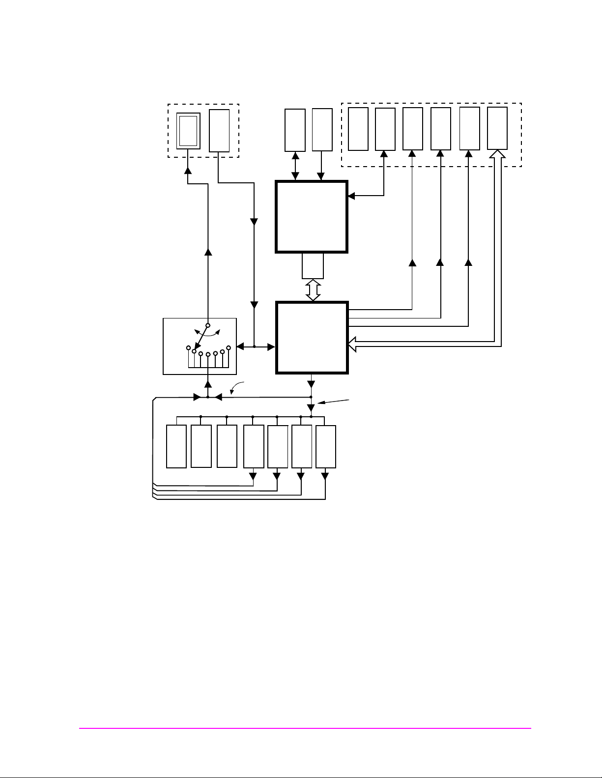
Figure 1-1 Manual Control Mode
Main Menu
Using HP-IB
Overview of the Test Set
KEY-
Display
FRONT PANEL
SCREEN
CONTROL
HARDWARE
KNOB
PAD/ROTARY
FRONT
PANEL
INFORMA-
MEMORY CARD
ROM DISK
IBASIC
CONTROLLER
#8
HP - IB
WARE
INSTRUMENT
CONTROL HARD-
#11
SERIAL I/F
SERIAL I/F
INSTRUMENT
SETUP
INFORMA-
SERIAL I/F
#9
#10
#16
PRINTER
PARALLEL
PRINTER
PARALLEL
#7
#15
HP - IB
RF GEN
AF GEN #1
AF GEN #2
AF ANALYZER
MEASUREMENT RESULTS AND DUT DATA
ANALYZER
SPECTRUM
OSCILLOSCOPE
RF ANALYZER
Chapter 1 PRELIMINARY 23
Page 26
Using HP-IB
Main Menu
Overview of the Test Set
Figure 1-2 Inter nal Automatic Control Mode
KEY-
KNOB
PAD/ROTARY
FRONT
PANEL
INFORMA-
SCREEN
Display
CONTROL
HARDWARE
FRONT PANEL
MEMORY CARD
ROM DISK
IBASIC
CONTROLLER
#8
HP - IB
WARE
INSTRUMEN T
CONTROL HARD-
#11
SERIAL I/F
SERIAL I/F
INSTRUMENT
SETUP
INFORMA-
SERIAL I/F
#9
#10
#16
PRINTER
PARALLEL
PRINTER
PARALLEL
#7
#15
HP - IB
RF GEN
AF GEN #1
AF GEN #2
AF ANALYZER
MEASUREMENT RESULTS AND DUT DATA
ANALYZER
SPECTRUM
OSCILLOSCOPE
RF ANALYZER
24 Chapter 1 PRELIMINARY
Page 27

Getting St ar te d
Main Menu
What is HP-I B?
The Hewlett-Packard Interface Bus (HP-IB) is Hewlett-Packard’s
implementation of the IEEE 488.1-1987 Standard Digital Interface for
Programmable Instrumentation. Incorporation of the HP-IB into the
Test Set provides several valuable capabilities:
• Programs running in the Test Set’s IBASIC Controller can control
all the Test Set’s functions using its internal HP-IB. This capability
provides a single-instrument automated test system. (The HP 11807
Radio Test Software utilizes this capability.)
• Programs running in the Test Set’s IBASIC Controller can control
other instruments connected to the external HP-IB.
• An external controller, connected to the external HP-IB, can
remotely control the Test Set.
Using HP-IB
Getting Started
• An HP-IB printer, connected to the external HP-IB, can be used to
print test results and full screen images.
HP-IB Infor mation Provided in Th is M anua l
What Is Explained
• How to configure the Test Set for HP-IB operation
• How to make an instrument setting over HP-IB
• How to read-back instrument settings over HP-IB
• How to make measurements over HP-IB
• How to connect external PCs, terminals or controll ers to the Test Set
• HP-IB command syntax for the Test Set
• IBASIC program development
• IBASIC program transfer over HP-IB
• Various advanced functions such as, increasing measurement
throughput, status reporting, error reporting, pass control, and so
forth
Chapter 1 PRELIMINARY 25
Page 28

Using HP-IB
Main Menu
Getting Started
What Is Not Explained
• HP-IB (IEEE 488.1, 488.2) theory of operation
• HP-IB electrical specifications
• HP-IB connector pin functions
•
•
• IBASIC programming (other than general guidelines related to
HP-IB)2
General HP-IB Programming Guidelines
The following guidelines should be considered when developing
programs which control the Test Set through HP-IB:
• Guideline #1.
1. Bring the Test Set to its preset state using the front-panel
PRESET key. This initial step allows you to start developing
the measurement sequence with most fields in a known state.
1
2. Make the measurement manually using the front-panel
controls of the Test Set. Record, in sequential order, the
screens selected and the settings made within each screen. The
record of the screens selected and setti ngs made in eac h screen
becomes the measurement procedure.
3. Record the measurement result(s).
4. Develop the program using the measurement procedure
generated in
step 2. Be sure to start the programmatic
measurement sequence by bringing the Test Set to its preset
state using the *RST Common Command. As the
measurement procedure requires changing screens, use the
DISPlay command to select the desired screen followed by the
correct commands to set the desired field(s).
NOTE When IBASIC programs are running the display is dedicated to the
IBASIC Controller for program and graphics display. This means
instrument front panels are not displayed when an IBASIC program is
running. However, the DISPlay <screen> command causes all setting
and measurement fields in the <screen> to be accessible
programmatically. Attempting to read from a screen that has not been
made acce ssible by the D IS Play com mand wil l cau se
HP-IB Err or :−420 Query UNTERMINATED, or
HP-IB Err or : −113 Undefined header
26 Chapter 1 PRELIMINARY
1. Refer to the Tuto rial Description of the Hewlett-Packard Int erface Bus
(HP P/N 5952-0156) for detailed informat ion on H P-I B theory and operation .
2. Refer to the HP Instru m e nt BAS IC Users Handbo o k (HP P/N E2083-90005) for
more information on the IBASIC Version 2.0 language.
Page 29

Using HP-IB
Main Menu
Getting Started
Make sure the desired measurement is in the ON sta te. This is
the preset state for most measurements. However, if a
previous program has set the state to OFF, the measurement
will not be available. Attempting to read from a measurement
field that is not in t he ON state will cause HP-IB Error:−420
Query UNT ER MI NA TE D.
5. If the trigger mode has been changed, trigger a reading.
NOTE Triggering is set to FULL SETTling and REPetitive RETRiggering
after receipt of the *RST Common Command. These settings cause the
Test Set to trigger itself and a separate trigger command is not
necessary.
6. Send the MEASure query command to initiate a reading. This
will place the measured value into the Test Set’s Output
Queue.
NOTE When making AF Analyzer SINAD, Distortion, Signal to Noise Ratio,
AF Frequency, DC Level, or Current measurements, the measurement
type must first be selected using the SELect command.
For example, MEAS:AFR:SEL'SINAD' followed by MEAS:AFR:SINAD?
7. Use the ENTER statement to transfer the measured value to a
variable within the context of the program.
Chapter 1 PRELIMINARY 27
Page 30

Using HP-IB
Main Menu
Getting Started
The following example program illustrates how to make settings
and then take a reading from the Test Set. This setup takes a
reading from the spectrum analyzer marker after tuning it to the
RF generator’s output frequency.
Example
10 Addr=714
20 OUTPUT Addr;"*RST" !Preset to known state
30 OUTPUT Addr;"TRIG:MODE:RETR SING" !Sets single trigger
40 OUTPUT Addr;"DISP RFG" !Selects the RF Gen screen
50 OUTPUT Addr;"AFG1:FM:STAT OFF" !Turns FM OFF
60 OUTPUT Addr;"RFG:AMPL -66 DBM" !Sets RF Gen ampl to -66 dBm
70 OUTPUT Addr;"RFG:FREQ 500 MHZ" !Sets RF Gen freq to 500 MHz
80 OUTPUT Addr;"RFG:AMPL:STAT ON" !Turns RF Gen output ON
90 OUTPUT Addr;"DISP SAN"!Selects Spectrum Analyzer’s screen
100 OUTPUT Addr;"SAN:CRF 500 MHZ" !Center Frequency 500 MHz
110 ! -------------------MEASUREMENT SEQUENCE------------------120 OUTPUT Addr;"TRIG" !Triggers reading
130 OUTPUT Addr;"MEAS:SAN:MARK:LEV?" !Query of Spectrum
140 !Analyzer’s mark er level
150 ENTER Addr;Lvl !Places measured value in variable Lvl
160 DISP Lvl!Displays value of Lvl
170 END
The RF Generator’s output port and the Spectrum Analyzer’s
input port are preset to the RF IN/OUT port. This allows the
Spectrum Analyzer to measure the RF Generator with no
external connections. The Spectrum Analyzer marker is always
tuned to the center frequency of the Spectrum Analyzer after
preset. With the RF Generator’s output port and Spectrum
Analyzer input port bo th d irec ted to the RF IN/OUT port, the two
will internally couple wi th 46 dB of gain, giving a measured value
of approximately −20 dBm. While not a no rmal mode of ope rati on
this setup is convenient for demonstration since no external
cables are required. This also illustrates the value of starting
from the preset state since fewer programming commands are
required.
28 Chapter 1 PRELIMINARY
Page 31

• Guideline #2.
Main Menu
If the program stops or “hangs up” when trying to ENTER a
measured value, it is most likely that the desired measurement
field is not available. There are several reasons that can happen:
1. The screen where the measurement field is located has not
been DISPlayed before querying the measurement field.
2. The measurement is not turned ON.
3. The squelch control i s set too high. If a measurement is turned
ON but is not available due to the Squelch setting, the
measurement field contains four dashes
(- - - -). This is a valid state. The Test Set is waiting for a signal
of sufficient strength to unsquelch the receiver before making
a measurement. If a measurement field which is squelched is
queried the Test Set will wait indefinitely for the receiver to
unsquelch and return a measured value.
4. The RF Analyzer’s Input Port is set to ANT (antenna) while
trying to read TX power. TX power is not measurable with the
Input Port set to ANT. The TX power measurement field will
display four dashes (- - - -) indicating the measurement is
unavailable.
Using HP-IB
Getting Started
5. The input signal to the Test Set is very unstable causing the
Test Set to continuously autorange. This condition will be
apparent if an attempt is made to make the measurement
manually.
6. Trigger mode has been set to single trigger
(TRIG:MODE:RETRig SINGle) and a new measurement cycle
has not been triggered before attempting to read the measure d
value.
7. The program is attempting to make an FM deviation or AM
depth measurement while in the RX TEST screen. FM or AM
measurements are not av ailable in the RX TEST screen. FM or
AM measurements are made from the AF Analyzer screen by
setting the AF Anl In field to FM or AM Demod.
• Guideline #3.
The syntax diagrams in
where single quotes are needed and where spaces are needed.
Example
OUTPUT 714;"DISP<space>AFAN"
OUTPUT 714;"AFAN:DEMP<space>’Off’"
chapter 5, "HP-IB Command Dictionary," show
Chapter 1 PRELIMINARY 29
Improper use of single quotes and spaces will cause,
HP-IB Error:−103 Invalid Se par at or
Page 32

Using HP-IB
Main Menu
Getting Started
• Guideline #4.
When making settings to fields that can be turned OFF with the
STATe ON/OFF command (refer to the
Dictionary"
), make sure the STATe is ON if the program uses that
Chapter 5, "HP-IB Command
field. Note that if the STATe is OFF, just setting a numeric value
in the field will not change the STATe to ON. This is different
than front-panel operation whereby the process of selecting the
field and entering a value automatically sets the STATe to ON.
Programmatically, fields must be explicitly set to the ON state if
they are in the OFF state.
For example, the following command line would set a new AMPS
ENCoder SAT tone deviation and then turn on the SAT tone (note
the use of the ; to back up one level in the command hierarchy so
that more than one command can be executed in a single line):
Example
OUTPUT 714;"ENC: AMPS :SAT :FM 2.1 KHZ; FM:S TAT ON"
To just turn on the SAT tone without changing the current
setting the following commands would be used:
Example
OUTPUT 714;"ENC:AMPS:SAT:FM:STAT ON"
Control Annunciators
The letters and symbols at the top right corner of the display indicate
these conditions:
• R indicates the Test Set is in remote mode. The Test Set can be put
into the remote mode by an external controller or by an IBASIC
program running on the built-in IBASIC controller.
• L indicates that the Test Set has been addressed to Listen.
• T indicates that the Test Set has been addressed to Talk.
• S indicates that the Test Set has sent the Require Service message
by setting the Service Request (SRQ) bus line true. (See
Reporting" on page 270
• C indicates that the Tes t Set is currentl y the Ac tive Control ler on the
bus.
"Status
.)
30 Chapter 1 PRELIMINARY
• * indicates that an IBASIC program is running.
• ? indicates that an IBASIC program is waiting for a user response.
• - indicates that an IBASIC program is paused.
Page 33

Preparing the Test Set For HP-IB Use
Main Menu
1. If other HP-IB devices are in the syste m, attach an HP-IB cable f rom
the Test Set’s HP-IB connector to any one of the other devices in the
test system.
2. Access the I/O CONFIGURE screen and perform the following steps:
a. Set the Test Set’s HP-IB address using the HP-IB Adr s field.
b. Set the Test Set’s HP-IB Controller capability using the Mode
field.
• Talk&Listen configures the Test Set to not be the System
Controller. The Test Set has Active Controller capability (take
control/pass control) in this mode. Use this setting if the Test
Set will be controlled through HP-IB from an external
controller.
• Control configures the Test Set to be the System Controller.
Use this setting if the Test Set will be the only controller on
the HP-IB. Selecting the Control mode automatically makes
the Test Set the Active Controller.
Using HP-IB
Getting Started
NOTE Only one System Controller can be configured in an HP-IB system.
Refer to "Passing Control" on page 337 for further information.
3. If an HP-IB printer is or will be connected to the Test Set’s HP-IB
connector then,
a. access the PRINT CONFIGURE screen.
b. select one of the s upported HP- IB printer models using the Model
field.
c. set the Printer Port field to HP-IB.
d. set the printer address using the Printer Address field.
Chapter 1 PRELIMINARY 31
Page 34

Using HP-IB
Main Menu
Getting Started
Using the HP-IB with the Te st Set’s buil t- in IB ASIC Contr ol le r
The Test Set has two HP - IB interfaces, a n internal-only HP -IB at select
code 8 and an external HP-IB at select code 7. The HP-IB at select code
8 is only available to the built-in IBASIC Controller and is used
exclusively for communication between the IBASIC Controller and the
Test Set. The HP-IB at select code 7 serves three purposes:
1. It allows the Test Set to be controlled by an external controller
2. It allows the Test Set to print to an external HP-IB printer
3. It allows the built-in IBASIC Controller to control external HP-IB
devices
IBASIC programs running on the Test Set’s IBASIC Controller must
use the internal-only HP-IB at select code 8 to control the Test Set.
IBASIC programs would use the external HP-IB at select code 7 to
control HP-IB devices connected to the HP-IB connector.
NOTE Refer to "Overv iew of the Test Set" on page 18 for a detailed explanation of
the Test Set’s architecture.
When using a BASIC la nguage Wo rksta tion with a n HP-IB interface at
select code 7 to control the Test Set, HP-IB commands would look like
this:
Example
! This command is sent to the Test Set at address 14.
OUTPUT 714;"*RST"
! This command is sent to another instrument whose address is 19.
OUTPUT 719;"*RST"
When executing the same commands on the Test Set’s IBASIC
Controller, the commands would look like this:
Example
OUTPUT 814;"*RST"
! Command sent to internal-only HP-IB at select code 8,
! Test Set’s address does not change
OUTPUT 719;"*RST"
! Command sent to external HP-IB at select code 7,
! other instrument’s address does not change.
32 Chapter 1 PRELIMINARY
Page 35

Basic Programming Examples
Main Menu
The following simple examples illustrate the basic approach to
controlling the Test Set through the HP-IB. The punctuation and
command syntax used for these examples is given in
Command Dictionary"
The bus address 714 used in the following BASIC language examples
assumes an HP-IB interface at select code 7, and a Test Set HP-IB
address of 14. All examples as sume an external contr oller i s being used.
To Change a Field’s Setting over HP-IB
1. Use the DISPlay command to access the screen containing the field
whose setting is to be changed.
2. Make the desired setting using the proper command syntax (ref er to
Chapter 5, "HP-IB Command Dictionary" for proper syntax).
The following example makes several instrument setting changes:
.
Using HP-IB
Getting Started
Chapter 5, "HP-IB
Example
OUTPUT 714;"DISP RFG" !Display the RF Generator screen.
OUTPUT 714;"RFG:FREQ 850 MHZ" !Set the RF Gen Freq to 850 MHz.
OUTPUT 714;"RFG:OUTP ’DUPL’"!Set the Output Port to Duplex.
OUTPUT 714;"DISP AFAN"!Display the AF Analyzer screen.
OUTPUT 714;"AFAN:INP ’FM DEMOD’"!Set the AF Anl In to FM Demod.
To Read a Field’s Setting over HP-IB37
1. Use the DISPlay command to access the screen containing the field
whose setting is to be read.
2. Use the Query form of the syntax for that field to place the setting
value into the Test Set’s output buffer.
3. Enter the value into the correct variable type within the program
context (refer to
variable type).
The following example reads several fields.
Example
OUTPUT 714;"DISP AFAN"!Display the AF Analyzer screen.
OUTPUT 714;"AFAN:INP?"!Query the AF Anl In field
ENTER 714;Af_input$ !Enter returned value into a string ariable.
OUTPUT 714;"DISP RFG"!Display the RF Generator screen
OUTPUT 714;"RFG:FREQ?"!Query the RF Gen Frequency field.
ENTER 714;Freq !Enter the returned value into a numeric variable
Chapter 5, "HP-IB Command Dictionary", for proper
Chapter 1 PRELIMINARY 33
Page 36

Using HP-IB
Main Menu
Getting Started
NOTE When querying measurements or settings through HP-IB, the Test Set
always returns numeric values in HP-IB Units or Attribute Units,
regardless of the current Display Units setting. Refer to "HP-IB U nits
(UNITs)" on page 68
and "Attribute Units (AUNits)" on page 70 for further
information.
To Make a Simple Measurement
The basic method for making a measurement is very similar to the
method used to read a field setting.
1. Use the DISPlay command to access the screen containing the
desired measurement.
2. Use the MEASure form of the syntax for that measurement to place
the measured value into the Test Set’s output buffer.
3. Enter the value into the correct variable type within the program
context (refer to
variab le t ype).
Chapter 5, "HP-IB Command Dictionary" for proper
The following example measures the power of an RF signal.
Example
!Display the RF Analyzer screen.
OUTPUT 714;"DISP RFAN"
!Measure the RF power and place result in output buffer.
OUTPUT 714;"MEAS:RFR:POW?"
!Enter the measured value into a numeric variable.
ENTER 714;Tx_power
The above example is very simple and is designed to demonstrate the
fundamental procedure for obtaining a measurement result. Many
other factors must be considered when designing a measurement
procedure, such as instrument settings, signal routing, settling time,
filtering, triggering and measurement speed.
34 Chapter 1 PRELIMINARY
Page 37

Remote Operation
Main Menu
The Test Set can be operated remotely through the Hewlett-Packard
Interface Bus (HP-IB). Except as other wise not ed, the Test Se t compli es
with the IEEE
488.1-1987 and IEEE 488.2-1987 Standards. Bus compatibility,
programming and data formats are described in the following sections.
Using HP-IB
Remote Operation
All front-panel functions, except those listed in
table 1-1, are
programmable through HP-IB.
Table 1-1 Non-Programmable Front Panel Functions
Function Comment
ON/OFF Power Switch
Volume Control Knob
Squelch Control Knob The position of the Squelch Control knob cannot be
programmed. However squelc h can be programmed to eith er
the Open or Fixed posi t i on. Refer to the Test Set’s User’s Guide
for more i nf o rm ation.
Cursor Control Knob
SHIFT Key
CANCEL Key
YES Key
NO Key
ENTER Key
Backspace (left-arrow) Key
Chapter 1 PRELIMINARY 35
PREV Key
HOLD (SHIFT, PREV Keys)
PRINT (SHIFT, TESTS Keys)
ADRS (SHIFT, LOCAL Keys)
ASSIGN (SHIFT, k4 Keys)
RELEASE (SHIFT, k5 Keys)
Page 38

Using HP-IB
Main Menu
Remote Operation
Remote Capabilities
Conformance t o the IEEE 488.1-1987 Standard
For all IEEE 488.1 functions implemented, the Test Set adheres to the
rules and procedures as outlined in that Standard.
Conformance t o the IEEE 488.2-1987 Standard
For all IEEE 488.2 functions implemented, the Test Set adheres to the
rules and procedures a s outl ined in that Standard wit h the ex c ept ion of
the *OPC Common Command. Refer to the *OPC Common Command
description.
IEEE 488.1 Interface Functio ns
The interface functions that the Test Set implements are listed in table
.
1-2
Table 1-2 Test Set IEEE 488.1 Interface Function Capabilities
Function Capability
Talker T6: No Talk Only Mode
Extended Talke r T0: No Extende d Talk er Cap abilit y
Listener L4: No Listen Only Mode
Extended Listener LE0: No Extended Listener
Capability
Source Handshak e SH1: Complete Capabi lity
Acceptor Handshake AH1: Complete Capability
Remote/Local RL1: Complete Capability
Service Request SR1: Comple te Cap ability
Parallel Poll PP0: No Parallel Poll Capability
Device Clear DC1: Comple te C ap abilit y
Device Trigge r DT1: Comp lete Ca pability
Controller C1: System Con trolle r
C3: Send REN
C4: Respond to SRQ
C11:No Pass Co ntr o l to Self, No
Parallel Pol l
36 Chapter 1 PRELIMINARY
Drivers E2: Tri-State Driv ers
Page 39

Addre ssi ng
Main Menu
Factory Set Address
The Test Set’s HP-IB address is set to decimal 14 at the factory. The
address can be changed by following the instructions in "Setting the Test
Set’s Bus Address" on page 37
Extended Addressing
Extended addressing (secondary command) capability is not
implemented in the Test Set.
Multiple Add re ss ing
Multiple addressing capability is not implemented in the Test Set.
Using HP-IB
Addressing
.
Setting the Test Set’s Bus Address
The Test Set’s HP-IB bus address is set using the HP-IB Adrs field
which is located on the I/O CONFIGURE screen. To set the HP-IB bus
address; select the I/O CONFIGURE screen and position the cursor
next to the HP-IB Adrs field. The address can be set from decimal 0 to
30 using the numeric DATA keys, or by pushing and then rotating the
Cursor Control knob. There are no DIP switches for setting the HP-IB
bus address in the Test Set. The new setting is retained when the Test
Set is turned off.
Displaying the Bus Address
The Test Set’s HP-IB bus address can be displayed by pressing and
releasing the SHIFT key, then the LOCAL key. The address is
displayed in the upper left-hand corner of the display screen.
Chapter 1 PRELIMINARY 37
Page 40

Using HP-IB
Main Menu
IEEE 488.1 Remote Interface Message Capabilities
IEEE 488.1 Remote Interface Messag e Ca pabilities
The remote interface message capabilities of the Test Set and the
associated IEEE 488.1 messages and control lines are listed in table 1.
38 Chapter 1 PRELIMINARY
Page 41

IEEE 488.1 Remote Interface Message Capabilities
Main Menu
Table 1 Test Set IEEE 488.1 Interface Message Capability
Using HP-IB
Message Type Implemented Response
Data Yes All front-panel
functions, except those
listed in table 1-2 on
page 36, are
programmable. The
Test Set can send
status byte, message
and setting
information . All
measurement results
(except dashed “- - - -”
displays) and e rr or
messages are available
through the bus.
Remote Yes Remote programming
mode is entered when
the Remote Enable
(REN) bus con trol line
is true and the Test Set
is addressed to listen.
The R annunciator will
appear in the
upper- ri gh t co r ne r o f
the display screen when
the Test Set is in
remote mode. All
front-panel keys are
disabled (except for the
LOCAL key, POWER
switch, Volu m e con trol
and Squelch control
knobs). When the Test
Set enters remote
mode the output signals
and internal settin gs
remain unchanged,
except that triggering is
reset to the state it was
last set to in remote
mode (Refer to
"Triggering
Measurements" on page
255).
IEEE 488.1
Message
DAB
END
MTA
MLA
OTA
REN
MLA
Chapter 1 PRELIMINARY 39
Page 42

Using HP-IB
Main Menu
IEEE 488.1 Remote Interface Message Capabilities
Message Type Implemented Response
Local Yes The Test Set retu rns to
local mode (full
front-panel co ntrol)
when either the Go To
Local (G TL) bus
comma nd is rec e i ve d ,
the front-panel LOCAL
key is pressed or the
REN line goes false.
When the Test Set
returns to lo cal mode
the output signals and
internal settings
remain unchanged,
except that triggering is
reset to
TRIG :MODE:SETT
FULL;RETR REP. The
LOCAL key will not
function if the Test Set
is in the local lockout
mode.
IEEE 488.1
Messag e
GTL
MLA
Local Lo ckout Yes Loca l Lo ckou t disables
all front-panel keys
including the LOCAL
key. Only the Syst em
Cont roller or t he
POWER switch can
return the Test Set to
local mode (fron t-pa ne l
control ) .
Clear L o ck o u t/
Set Local
Yes The Test Set returns to
local mode (fron t-pa ne l
control) and local
lockout is cleared whe n
the REN bus control
line goes false. When
the T e st Set returns to
local mode the output
signals and internal
settings remain
unchanged, except that
triggering is set to
TRIG :MODE:SETT
FULL;RETR REP.
LLO
REN
40 Chapter 1 PRELIMINARY
Page 43

Using HP-IB
Main Menu
IEEE 488.1 Remote Interface Message Capabilities
Message Type Implemented Response
Service Request Yes The Test Set sets the
Service Request (SRQ)
bus line true if any of
the enabled conditions
in the Status Byte
Register, as defined by
the Service Request
Enable Register, are
true.
Status Byte Yes The Test Se t resp ond s
to a Serial Poll Enable
(SPE) bus command by
sending an 8-bit status
byte when addressed to
talk. Bit 6 will be true,
logic 1, if the Test Set
has sent the SRQ
message
Status Bit No The Test Set does not
have the capability to
respond to a Parallel
Poll.
IEEE 488.1
Message
SRQ
SPE
SPD
STB
MTA
PPE
PPD
PPU
PPC
IDY
Chapter 1 PRELIMINARY 41
Page 44

Using HP-IB
Main Menu
IEEE 488.1 Remote Interface Message Capabilities
Message Type Implemented Response
Clear Yes This message clears the
Input Buffer and
Output Queue , clear s
any commands in
process, puts the Test
Set into the Operatio n
Complete idle state
and prepares the Test
Set to receive new
commands. The Device
Clear (DCL) or Sel ected
Device Clear (SDC) bus
commands
• do not change any
settings or stored
data (except as
noted previously)
• do not interrupt
front panel I/O or
any Test Set
operation in
progress (except
as noted
previously)
IEEE 488.1
Messag e
DCL
SDC
MLA
• do not change the
contents of the
Status Byte
Register (other
than clearing the
MAV bit as a
consequence of
clearing the
Output Queue).
The Test Set respo nd s
equally to DCL or SDC
bus command s.
42 Chapter 1 PRELIMINARY
Page 45

Using HP-IB
Main Menu
IEEE 488.1 Remote Interface Message Capabilities
Message Type Implemented Response
Trigger Ye s If in remo te
programming mode and
addressed to listen, the
Test Set makes a
triggered
measurement following
the trigger conditions
currently in effect in
the instrument. The
Test Set respo nd s
equally to the Group
Execute Trigger (GET)
bus command or the
*TRG Common
Command.
Take Control Yes The Test Set begins to
act as the Active
Contro lle r o n the bus.
Abort Yes The Test Set stops
talking and list eni ng
IEEE 488.1
Message
GET
MLA
TCT
MTA
IFC
Chapter 1 PRELIMINARY 43
Page 46

Using HP-IB
Main Menu
Remote/Local Modes
Remote/Local Modes
Remote Mode
In Remote mode all front-panel keys are disabled (except for the
LOCAL key, POWER switch, Volume control and Squelch control). The
LOCAL key is only disabled by the Local Lockout bus command. When
in Remote mode and addressed to Listen the Test Set responds to the
Data, Remote, Local, Clear (SDC), and Trigger messages. When the
Test Set is in Remote mode, the R annunciator will be displayed in the
upper right corne r of the di splay screen and tri ggering is set t o the state
it was last set to in Remote mode (if no previous setting, the default is
FULL SETTling and REPetitive RETRiggering). When the Test Set is
being addressed to Listen or Talk the L or T annunciators will be
displayed in the upper-right corner of the display screen.
Local Mode
In Local mode the Test Set’s front-panel controls are fully operational.
The Test Set uses FULL SETTling and REPetitive RETRiggering in
Local mode. When the Test Set is being addressed to Li sten or Tal k the
L or T annunciators will be displayed in the upper-right corner of the
display screen.
Remote or Local Mode
When addressed to Talk in Remote or Local mode, the Test Set can
issue the Data and Status Byte messages and respond to the Take
Control message. In additi on the Test Set can issue the Service Request
Message (SRQ). Regardless of whether it is addressed to talk or listen,
the Test Set will respond to the Clear (DCL), Local Lockout, Clear
Lockout/Set Local, and Abort messages.
44 Chapter 1 PRELIMINARY
Page 47

Local To Remote Transitions
Main Menu
The Test Set switches from Local to Remote mode upon receipt of the
Remote message (REN bus line true and Test Set is addressed to
listen). No instrument settings are changed by the transition from
Local to Remote m ode, b ut triggering is set to the s ta te it was las t set to
in Remote mode (if no previous setting, the default is FULL SETTling
and REPetitive RETRiggering). The R annunciator in the upper-right
corner of the display is turned on.
When the Test Set makes a transition from local to remote mode, all
currently active measurements are flagged as invalid causing any
currently available measurement results to become unavailable. If the
HP-IB trigger mode is :RETR REP then a new measurement cycle is
started and measurement results will be available for all active
measurements when valid results have been obtained. If the HP-IB
trigger mode is :RETR SING then a measurement cycle must be sta rted
by issuing a trigger event. Refer to
for more information.
Using HP-IB
Remote/Local Modes
"Triggering Measurements" on page 255
Remote To Local Transitions
The Test Set switches from Remote to Local mode upon receipt of the
Local message (Go To Lo cal bus messa ge is sent an d Te st Set is
addressed to listen) or receipt of the Clear Lockout/Set Local message
(REN bus line false). No instrument settings are changed by the
transition from Remote to Local mode, but triggering is reset to FULL
SETTling and REPetitive RETRiggering. The R annunciator in the
upper right corner of the display is turned off.
If it is not in Local Lockout mode the Test Set switches from Remote to
Local mode whenever the front-panel LOCAL key is pressed.
If the Test Set was in Local Lockout mode when the Local message was
received, front-panel control is returned, but Local Lockout mode is not
cleared. Unless the Test Set receives the Clear Lockout/Set Local
message, the Test Set will still be in Local Lockout mode the next time
it goes to the Remote mode.
Chapter 1 PRELIMINARY 45
Page 48

Using HP-IB
Main Menu
Remote/Local Modes
Local Lockout
The Local Lockout mode disables the front-panel LOCAL key and
allows return to Local mode only by commands from the System
Controller (Clear Lockout/Set Local message).
When a data transmission to the Test Set is interrupted, which can
happen if the LOCAL key is pressed, the data being transmitted m ay be
lost. This can leave the Test Set in an unknown state. The Local
Lockout mode prevents loss of data or system control due to someone
unintentionally pressing front-panel keys.
NOTE Return to Local mode can also be accomplished by setting the POWER
switch to OFF and back to ON. However, returning to Local mode in
this way has the following disadvantages:
1. It defeats the purpose of the Local Lockout mode in that the Active
Controller will lose control of the test set.
2. Instrument configuration is reset to the power up condition thereby
losing the instrument configuration set by the Active Controller.
Clear Lockout/Se t Loc al
The Test Set returns to Local mode when it receives the Clear
Lockout/Set Local message. No instrument settings are changed by the
transition from Remote mode with Local Lockout to Local mode but
triggering is reset to FULL SETTling and REPetitive RETRiggering.
46 Chapter 1 PRELIMINARY
Page 49

2 Methods For Reading
Main Menu
Measurement Results
47
Page 50

Methods For Reading Measurement Results
Main Menu
Background
Background
One of the most common remote user interface operations performed on
an Test Set is to query and read a measurement result. Generally, this
operation is accomplished by sending the query command to the Test
Set, followed immediately by a request to read the requested
measurement result. Using Hewlett-Packard Rocky Mountain BASIC
(RMB) language, this operation would be written using the OUTPUT
and ENTER command as follows:
Query Example
OUTPUT 714;"MEAS:RFR:POW?"
ENTER 714;Power
Using this prog ramming s tr uc ture , the control progr a m will sta y on the
ENTER statement until it is satisfied - that is - until the Test Set has
returned the requested measurement result. This structure works
correctly as long as the Test S et r etur ns a va l id m easur ement r esult. If,
for some reason, the Test Set does not return a measurement resul t, the
control program becomes “hung” on the ENTER statement and program
execution effectively stops.
In order to prevent the control program from becoming “hung”
programmers usually enclose the operation with some form of timeout
function. The form of the timeout will of course depend upon the
programming language being used. The purpose of the timeout is to
specify a fixed amount of time that the control prog ram will wait for the
Test Set to return the requested result. After this time has expired the
control program will abandon the ENTER statement and try to take
some corrective action to regain control of the Test Set.
If the control program does not send the proper commands i n the prop er
sequence when trying to regain control of the Test Set, unexpected
operation will result. When this condition is encountered, power must
be cycled on the Test Set to regain control.
This situation can be avoided entirely by:
1. sending a Selected Device Clear (SDC) interface message to put the
Test Set’s HP-IB subsystem into a known state.
2. sending a command to terminate the requested measurement cycle.
These commands issued in this order will allow the control program to
regain control of the Test Set. Any other sequence of commands will
result in unexpected operation.
48 Chapter 2 PRELIMINARY
Page 51

Methods For Reading Measurement Results
Main Menu
Background
The following programs demonstrate a recommended technique for
querying and entering data from the Test Set. This technique will
prevent the Test Set from getting into a ‘hung’ state such that power
must be cycled on the Test Set to regain manual or programmatic
control.
There are a variety of programming constructs which can be used to
implement this technique. In the programming examples presented, a
function call is implemented which returns a numeric measurement
result. The function call has two pass parameters; the query command
(passed as a quoted string) and a time-out value (passed as a integer
number).
The time-out value represents how long you want to wait, in seconds,
for the Test Set to return a valid measurement result. If a valid
measurement result is not returned by the Test Set within the time-out
value, the function returns a very large number. The calling program
can check the value and take appropriate action.
The program examples are written so as to be self-explanatory. In
practice, the length of: variable names, line l abels, functio n names, etc.,
will be implementation dependent.
Chapter 2 PRELIMINARY 49
Page 52

Methods For Reading Measurement Results
Main Menu
HP BASIC ‘ON TIMEOUT’ Example Program
HP BASIC ‘ON TIMEOUT’ Example Program
The following example program demonstrates a recommended
technique which can be utilized in situations where a measurement
result timeout value of 32.767 seconds or less is adequate. In the HP
RMB language, the timeout pa rameter for the O N TIMEOUT command
has a maximum value of 32.767 seconds. If a timeout value of greater
than 32.767 seconds is required refer to the HP BASIC ‘MAV’ Bit
Example Program.
The measurement result timeout value is defined to mean the amount
of time the control pr ogram is willi ng to wait fo r the Test S et to return a
valid measurement result to the control program.
Lines 10 thru 230 in this example set up a measurement situation to
demonstrate the use of the rec ommended techni que. The r ecommended
technique is exampled in the Measure Function.
NOTE Lines 50 and 60 should be included in the beginning of all control
programs. These lines are required to ensure that the Test Set is
properly reset. This covers the case where the program was previously
run and was stopped with the Test Set in an error condition.
50 Chapter 2 PRELIMINARY
Page 53

Methods For Reading Measurement Results
Main Menu
HP BASIC ‘ON TIMEOUT’ Example Program
Timeout Example
10 COM /Io_names/ INTEGER Inst_addr,Bus_addr
20 CLEAR SCREEN
30 Inst_addr=714
40 Bus_addr=7
50 CLE AR In st_addr
60 OUTPUT Inst_addr;"TRIG:ABORT"
70 OUTPUT Inst_addr;"*RST"
80 OUTPUT Inst_addr;"DISP RFAN"
90 !
100 ! Execute a call to the Measure function with a request to measure RF
110 ! power. The time out value is specified as 10 seconds. The value
120 ! returned by the function is assigned to the variable Measure_result.
130 !
140 Measure_result=FNMeasure("MEAS:RFR:POW?",10)
150 !
160 ! Check the result of the function call.
170 !
180 IF Measure_result=9.E+99 THEN
190 PRINT "Measurement failed."
200 ELSE
210 PRINT "Power = ";Measure_result
220 END I F
230 END
240 !***********************************************************
250 ! Recommended Technique:
260 !***********************************************************
270 DEF FNMeasure(Query_command$,Time_out_value)
280 COM /Io_names/ INTEGER Inst_addr,Bus_addr
290 DISABLE
300 ON TIMEOUT Bus_addr,Time_out_value RECOVER Timed_out
310 OUTPUT Inst_addr;"TRIG:MODE:RETR SING;:TRIG:IMM"
320 OUTPUT Inst_addr;Query_command$
330 ENTE R In st_addr;Resu lt
340 OUTPUT Inst_addr;"TRIG:MODE:RETR REP"
350 ENABLE
360 RETURN Result
370 Time d_out:!
380 ON TIMEOUT Bus_addr,Time_out_value GOTO Cannot_recover
390 CLEAR Inst_add r
400 OUTPUT Inst_addr;"TRIG:ABORT;MODE:RETR REP"
410 ENABLE
420 RETURN 9.E+99
430 Cannot_recover:!
440 DISP "Cannot regain control of Test Set."
450 STOP
460 FNEN D
Chapter 2 PRELIMINARY 51
Page 54

Methods For Reading Measurement Results
Main Menu
HP BASIC ‘ON TIMEOUT’ Example Program
Comments for Recommended Routine
Table 2-1
Program
Line
Number
50 Send a Selected Device Clear (SDC) to the Test Set to put the HP-IB subsystem
into a known state. This allows the control program to regain programmatic
control of the Test Set if it is in an error state when the progr am begin s to run.
60 Command the Test Set to abort the currently executing measurement cycle.
This will force the T es t Se t to stop waiting for any meas ur ement results to be
available from measurements which may be in an invalid state when the
program begins to run.
290 Turn event initiated branche s off (e xcept ON E N D, ON ERROR and ON
TIMEOUT) to ensur e that th e Meas ur e fun ction will not be exited until it is
finished.
300 Set up a timeout for any I/O activity on the HP-IB. This will allow the function
to recov e r if the bu s hangs for any reason.
Comments
310 Set the triggering mode to single followed by a trigger immediate command.
This ensures that a new measurement cycle will be started when the
TRIG:IMM command is sent. This sequence, that is: set to single trigger and
then send a trigger command, guarantees that the measurement result
returned to the EN T ER statem e n t will acc ur ate ly refle c t the state of th e DUT
when the TRIG:IMM command was sent. The ’IMM’ keyword is optional.
320 Send the query command passed to the Measure function to the Test Set.
330 Read the measurement result.
340 Set the trigger mode to repet itive retr iggering. Setti ng th e trigger mode to
repetitive will be im p lem en tati on depe nde nt .
350 Re-enab le even t initiat ed br anc hin g. If any event in itiated bran ch es we re
logged while the Me asu re func tio n wa s ex ecuting they will be executed when
system priority permits.
360 Exit the Measure function and return the result value.
370 The following lines of code handle the case where the request for a
measurement result has timed out.
380 Set up a timeout for any I/O acti vit y on the HP-IB while t h e con t rol program is
trying to regain control of the Test Set. This will allow the function to gracefully
stop program execution if the control program cannot regai n c ontrol of the Test
Set. This timeo ut sh o uld on ly o cc ur if there is some type of har dware failure,
either in the Test Set or the external controller, which prevents them from
communicating via HP -IB.
52 Chapter 2 PRELIMINARY
390 Send a Selected Device Clear (SDC) to the Test Set to put the HP-IB subsystem
into a known state. This allows the control program to regain programmatic
contro l of the Test Set .
Page 55
Methods For Reading Measurement Results
Main Menu
HP BASIC ‘ON TIMEOUT’ Example Program
Program
Line
Number
400 Command the Test Set t o abort t he curr ently execu ting mea surement c ycle. Set
the trigger mode back to repetitive retriggering. Setting the Test Set back to
repetitive retrig gerin g will be implementat ion dep end e n t.
410 Re-enable event initiate d bran ching . If any event initiate d branches we r e
logged while the Measure function was executing they will be executed when
system priority permits.
420 Exit the Measure function and return a resu lt valu e of 9.E+99.
430 The following lines of code handle the case where the control program cannot
regain contro l of th e Test Se t. The act ion s tak e n in thi s se ction of the code will
be implementation dependen t . For the example case a message is displayed to
the operator and the program is stopped.
440 Display a message to the operator that the cont rol program cannot regain
control o f th e T e st S e t.
Comments
450 Stop execution of the control program.
Chapter 2 PRELIMINARY 53
Page 56

Methods For Reading Measurement Results
Main Menu
HP BAS IC ‘M A V’ Exam p le Progr a m
HP BASIC ‘MAV’ Example Program
The following HP RMB example program demonstrates a technique
which can be used in situations where a 32.767 measurement result
timeout value is not adequate.
Measurement result timeout value is defined to mean the amount of
time the control program is willing to wait for the Test Set to return a
valid measurement result to the control program.
The technique uses the MAV (Message Available) bit in the Test Set’s
HP-IB Status Byte to determine when there is data in the Output
Queue. A polling loop is used to query the Status byte. The timeout
duration for returning the measurement result is handled by the
polling loop. An HP-IB interface activity timeout is also set up to handle
time-outs resulting from problems with the HP-IB interface.
Lines 10 thru 230 in this example set up a measurement situation to
demonstrate the use of the rec ommended techni que. The r ecommended
technique is exampled in the Measure Function.
NOTE Lines 50 and 60 should be included in the beginning of all control
program. These lines are required to ensure that the Test Set is
properly reset. This covers the case where the program was previously
run and was stopped with the Test Set in an error condition.
54 Chapter 2 PRELIMINARY
Page 57

Methods For Reading Measurement Results
Main Menu
HP BASIC ‘MAV ’ Ex a mple Progra m
MAV Example
10 COM /Io_names/ INTEGER Inst_addr,Bus_addr
20 CLEAR SCREEN
30 Inst_addr=714
40 Bus_addr=7
50 CLE AR In st_addr
60 OUTPUT Inst_addr;"TRIG:ABORT"
70 OUTPUT Inst_addr;"*RST"
80 OUTPUT Inst_addr;"DISP RFAN"
90 !
100 ! Execute a call to the Measure function with a request to measure RF
110 ! power. The time out value is specified as 50 seconds. The value
120 ! returned by the function is assigned to the variable Measure_result.
130 !
140 Measure_result=FNMeasure("MEAS:RFR:POW?",50)
150 !
160 ! Check the result of the function call.
170 !
180 IF Measure_result=9.E+99 THEN
190 PRINT "Measurement failed."
200 ELSE
210 PRINT "Power = ";Measure_result
220 END I F
230 END
240 !***********************************************************
250 ! Recommended Technique:
260 !***********************************************************
270 DEF FNMeasure(Query_command$,Time_out_value)
280 COM /Io_names/ INTEGER Inst_addr,Bus_addr
290 DISA BLE
300 ON TIMEOUT Bus_addr,5 GOTO Timed_out
310 OUTPUT Inst_addr;"TRIG:MODE:RETR SING;:TRIG:IMM"
320 OUTP UT Inst_addr;Query_command$
330 Start_time=TIMEDATE
340 REPE AT
350 WAIT .1
360 Status_byte=SPOLL(Inst_addr)
370 IF BIT(Statu s_ byte,4 ) THE N
380 ENTER Inst_a dd r;Resu lt
390 OUTPUT Inst_addr;"TRIG:MODE:RETR REP"
400 ENABLE
410 RETURN Result
420 END IF
430 UNTIL TIMEDA TE -Start _t ime>=Ti me _out_value
440 Time d_out:!
450 ON TIMEOUT Bus_addr,5 GOTO Cannot_recover
460 CLEAR Inst_a dd r
470 OUTPUT Inst_addr;"TRIG:ABORT;MODE:RETR REP"
480 RETU RN 9.E+99
490 Cannot_recover: !
500 DISP "Cannot regain control of Test Set."
510 STOP
520 FNEN D
Chapter 2 PRELIMINARY 55
Page 58

Methods For Reading Measurement Results
Main Menu
HP BAS IC ‘M A V’ Exam p le Progr a m
Comments for Recommended Routine
Table 2-2 Comments for Measure Function from MAV Example Program
Program
Line
Number
50 Send a Selected Device Clear (SDC) to the Test Set to put the HP-IB subsystem
into a known state. This allows the control program to regain programmatic
control of the Test Set if it is in an error state when the progr am begin s to run.
60 Command the Test Set to abort the currently executing measurement cycle.
This will force the T es t Se t to stop waiting for any meas ur ement results to be
available from measurements which may be in an invalid state when the
program begins to run.
290 Turn event initiated branche s off (e xcept ON E N D, ON ERROR and ON
TIMEOUT) to ensur e that th e Meas ur e fun ction will not be exited until it is
finished.
300 Set up a 5 second timeout for any I/O activity on the HP-IB. This will allow the
function to recover if the bus hangs for any reason. The length of the timeout
will be implement a tion d ep end e nt.
Comments
310 Set the triggering mode to single followed by a trigger immediate command.
This ensures that a new measurement cycle will be started when the
TRIG:IMM command is sent. This sequence, that is: set to single trigger and
then send trigger command, guarantees that th e measurement result returned
to the ENTER statement will accurately reflec t the state of the DUT when the
TRIG:IMM command was sent. The ’IMM’ keyword is optional.
320 Send the query command passed to the Measure function to the Test Set.
330 Establish a start time ag ains t whic h to com pare the me asur em ent result
timeout value passed to the Measure function.
340 Start the status byte polling loop.
350 Allow the Test Set some time (100 milliseconds) to process the measurement.
When polling the T es t Se t the polling loop must giv e th e Te st Set tim e to
process t he req uest e d measuremen t . Since HP- I B com m and proce ss i ng has a
higher system priority within the Test Set than measurement functions,
constantly sending HP-IB commands will result in longer measurement times.
360 Perform a serial poll to read the Status Byte from the Test Set. A serial poll is
used because the *STB Common Command cannot be processed by the Tes t Set
while a query is pending. Sending the *STB command will cause an
’HP-IB Error: -410 Query INTERRUPTED’ error.
370 Check bit 4, the Message Available bit (MAV), to see if it is set to ’1’. If it is,
then the requested measurement result is ready.
56 Chapter 2 PRELIMINARY
380 Read the measurement result.
390 Set the trigger mode to repet itive retr iggering. Setti ng th e trigger mode to
repetitive will be im p lem en tati on depe nde nt .
Page 59

Methods For Reading Measurement Results
Main Menu
HP BASIC ‘MAV ’ Ex a mple Progra m
Program
Line
Number
400 Re-enable event initiate d bran ching . If any event initiate d branches we r e
logged while the Measure function was executing they will be executed when
system priority permits.
410 Exit the Measure function and return the result value.
430 Check to see if the measurement result time out valu e has been equaled or
exceeded. If it has the polling loop will be exited.
440 The following lines of code handle the case where the request for a
measurement result has timed out because the polling loop has completed with
no result available .
450 Set up a timeout for any I/O activity on the HP-IB while the control program is
trying to regain control of the Test Set. This will allow the function to gracefully
stop program execu t i on if t he control progr am cann ot r egai n con t rol of the Test
Set. This timeout should only occur if ther e is some type of hardware failur e,
either in the Test Set or the external controller, which prevents them from
communicating via HP-IB.
Comments
460 Send a Selected Device Clear (SDC) to the Test Set to put the HP-IB subsystem
into a known state . This allo ws the control pro gr am to reg ain p rogr a mm atic
control o f th e T e st S e t.
470 Command the Test Set t o abort t he curr ently execu ting mea surement c ycle. Set
the trigger mode back to repetitive retriggering. Setting the Test Set back to
repetitive retrig gerin g will be implementat ion dep end e n t.
480 Exit the Measure function and return a resu lt valu e of 9.E+99.
490 The following lines of code handle the case where the control program cannot
regain contro l of th e Test Se t. The act ion s tak e n in thi s se ction of the code will
be implementation dependen t . For the example case a message is displayed to
the operator and the program is stopped.
500 Display a message to the operator that the cont rol program cannot regain
control o f th e T e st S e t.
510 Stop execution of the control program.
Chapter 2 PRELIMINARY 57
Page 60

Methods For Reading Measurement Results
Main Menu
HP BAS IC ‘M A V’ Exam p le Progr a m
58 Chapter 2 PRELIMINARY
Page 61

3 HP-IB Command Guidelines
Main Menu
59
Page 62

HP-IB Command Guidelines
Main Menu
Sequential and Overlapped Commands
Sequent ial and Ov erla pp ed Commands
IEEE 488.2 makes the distinction between sequential and overlapped
commands. Sequential commands complete their task before execution
of the next command can begin. Overlapped commands can run
concurrently, that is, a command following an overlapped command
may begin execution while t he over l apped com mand is stil l i n pro gr ess.
All commands in the Test Set are sequential.
The processing architecture of the Test Set allows it to accept
commands through the HP-IB while it is executing commands already
parsed into its command buffer. While this may appear to be
overlapped, commands are always executed sequentially in the order
received.
The process of executing a command can be divided into three steps:
1. Command is accepted from HP-IB and checked for proper structure
and param et er s.
2. Commands is sent to instrument hardware.
3. Instrument hardware fully responds after some time,
For example, in programming the Test Set’s RF Signal Generator it
takes < 150 ms after receipt of the frequency setting command for the
output signal to be within 100 Hz of the desired frequency. In the Test
Set, commands are considered to have “completed thei r task” at the end
of step 2. In manual operation all displayed measurement results take
into account the instrument hardware’s response time. When
programming measurements through HP-IB the Triggering mode
selected will determine whether the instrument’s response time is
accounted for automatically or if the control program must account for
it. Refer to
different Trigger modes available in the Test Set and their affect on
measurement results.
"Triggering Measurements" on page 255 for a discussion of the
∆t.
60 Chapter 3 PRELIMINARY
Page 63

Guidelines for Operation
Main Menu
The following topics discuss rules and guidelines for controlling the
Test Set through HP-IB.
Command Names
All command names of more than four characters have an alternate
abbreviated form using only upper case letters and, in some cases, a
single numeral. The commands are not c ase sens it iv e. Upper a nd lower
case cha racters can b e use d fo r all comman ds.
For example, to set the destination of AF Generator 1 to Audio Out, any
of the following command strings are valid:
Example
AFGENERATOR1:DESTINATION ’AUDIO OUT’
or
afgenerator1:destination ’audio out’
or
afg1:dest ’aud io out’
or
AFG1:DEST ’AUD IO OUT’
or
Afg1:Dest ’Aud io oUT’
HP-IB Command Guidelines
Guidelines for Operation
Chapter 3 PRELIMINARY 61
Page 64

HP-IB Command Guidelines
Main Menu
Guidelines for Operation
Command Punctuation
NOTE Programming Language Considerations
The punctuation rules for the Test Set’s HP-IB commands conform to
the IEEE 488.2 standard. It is possible that some programming
languages used on external controllers may not accept some of the
punctuation requirements. It is therefore necessa ry that the equivalent
form of the correct punctuation, as defined by the language, be used for
HP-IB operation. Improper punctuation will results in
. HP-IB Error: -102 Syntax Error
Using Quotes for String Entries
Quotation marks ' and " are used to select a non-numeric field setting.
The value is entered into the command line as a quoted alphanumeric
string.
Quotes are used with all Underlined (toggling) and One-of-many ( menu
choice) fie lds.
For example, to set the RF Generator’s Output Port field to Dupl
(duplex), the Dupl would be entered into the command string.
Example
RFG:OUTP ’Dupl’
or
RFG:OUTP "Dupl"
Using Sp ac es
When changing a field’s setting, a space must always precede the
setting value in the command string, regardless of the field type
(command<space>value).
Example
RFG:FREQ<space>850MHZ
RFG:ATT<space>’OFF’
Using Colons to Separate Commands
The HP-IB command syntax is structured using a control hierarchy
that is analogous to manual operation.
The control hierarchy for making a manual instrument setting using
the front-panel controls is as follows: first the screen is accessed, then
the desired field is selected, then the appropriate setting is made.
HP-IB commands use the same hierarchy. The colon (:) is used to
separate the different levels of the command hierarchy.
62 Chapter 3 PRELIMINARY
Page 65

HP-IB Command Guidelines
Main Menu
Guidelines for Operation
For example, to set the AF Analyzer input gain to 40 dB, the following
command syntax would be used:
Example
DISP AFAN
AFAN:INP:G AIN ’40 dB’
Using the Semicolon to Output Multiple Commands
Multiple commands can be output from one program line by s epar ating
the commands with a semicolon (;). The semicolon tells the Test Set’s
HP-IB command parser to back up one level of hierarchy and accept the
next command at the same level as the previous command.
For example, on one command line, it is possible to
1. access the AF ANALYZER screen,
2. set the AF Analyzer’s Input to AM Demod
3. set Filter 1 to 300 Hz HPF
4. set Filter 2 to 3kHz LPF
Example
DISP AFAN;AFAN:INP ’AM DEMOD’;FILT1 ’300Hz HPF’;FILT2 ’3kHz LPF’
The semicolon after the “DISP AFAN” command tells the Test Set’s
HP-IB command parser that the next command is at the same level in
the command hierarchy as the display command. Similarly, the
semicolon after the INP 'AM DEMOD' command tells the command
parser that the next command (FILT1 '300Hz HPF') is at the same
command level as the INP 'AM DEMOD' command.
Using the Semicolon and Colon to Output Multiple
Commands
A semicolon followed by a colon (;:) tells the HP-IB command parser
that the next command is at the top level of the command hierarchy.
This allows commands from different instruments to be output on one
command line. The following example sets the RF Analyzer’s tune
frequency to 850 MHz, and then sets the AF Analyzer’s input to FM
Demod.
Example
RFAN:FREQ 850MHZ;:AFAN:INP ’FM DEMOD’
Chapter 3 PRELIMINARY 63
Using Question Marks to Query Setting or Measurement
Fields
The question mark (?) is used to query (read-back) an instrument
setting or measurement value. To generate the query form of a
command, place the question mark immediately after the command.
Page 66

HP-IB Command Guidelines
Main Menu
Guidelines for Operation
Queried information must be read into the proper variable type within
the program context before it can be displayed, printed, or used as a
numeric value in the program.
Queried information is returned in the same format used to set the
value: queried numeric fields return numeric data; quoted string fields
return quoted string information.
For example, the following BASIC language progr am statement s query
the current setting of the AFGen 1 To field:
Example
!Query the AFGen1 To field
OUTPUT 714;"AFG1:DEST?"
!Enter queried value into a string variable.
ENTER 714;Afg1_to$
Specifying Units-of-Measure for Settings and Measurement
Results
Numeric settings and measurement results in the Test Set can be
displayed using one or more units-of-measure (V, mV, mV, Hz, kHz,
MHz…). When operating the Test Set manually, the units-of-measure
can be easily changed to disp lay measurement resul ts and field se ttings
in the most convenient format. HP-IB operation is similar to manual
operation in that the units-of-measure used to display numeric data can
be programmatically changed to the most convenient form.
NOTE When querying measurements or settings through HP-IB, the Test Set
always returns numeric values in HP-IB Units or Attribute Units,
regardless of the current Display Units setting. Refer to "HP-IB U nits
(UNITs)" on page 68
and "Attribute Units (AUNits)" on page 70 for further
information.
There are three sets of units-of-measure used in the Test Set: Display
Units,
HP-IB Units, and Attribute Units. Writing correct HP-IB programs
requires an understanding of how the Test Set deals with these
different sets of units-of-measure.
64 Chapter 3 PRELIMINARY
Page 67

HP-IB Command Guidelines
Main Menu
Guidelines for Operation
Display Units (DUNits)
Display Units are the units-of-measure used by the Test Set to display
numeric data (field settings and measurement results) on the
front-panel CRT display. For example, the RF Generator’s frequency
can be displayed in Hz, kHz, MHz and GHz. Similarly, the measured
TX Frequency can be displayed in Hz, kHz, MHz and GHz.
When evaluating an entered value for a numeric field, the Test Set
interprets the data it receives in terms of the Display Units currently
set. For example, if the Display Units for the RF Gen Freq field are
set to GHz and the operator tries to enter 500 into the field, an Input
value ou t of range error i s generated since the Test Set i nterpreted
the value as 500 GHz which is outside the valid frequency range of the
Test Set.
Changing Display Units. . Use the DUNits command to change the
units-of-measure used by the Test Set to display any field setting or
measurement result. For example, to change the Display Units setting
for the TX Power measurement field from W to dBm, the following
command would be used:
Example
MEAS:RFR:POW:DUN DBM
Display Units
DUNits Command Example
GHz
:MEAS:RFR:FREQ:ABS:DUN GHZ
MHz
:MEAS:RFR:FREQ:ABS:DUN MHZ
kHz
:MEAS:RFR:FREQ:ABS:DUN KHZ
Hz
:MEAS:RFR:FREQ:ABS:DUN HZ
ppm
:MEAS:RFR:FREQ:ERR:DUN PPM
%D
:MEAS:RFR:FREQ:ERR:DUN PCTDIFF
Chapter 3 PRELIMINARY 65
V
:MEAS:RFR: POW: DUN V
Page 68

HP-IB Command Guidelines
Main Menu
Guidelines for Operation
mV
:MEAS:RFR:POW:DUN MV
µV
:RFG:AMPL:DUN µV
dBµV
:RFG:AMPL:DUN DBµV
W
:MEAS:RFR:POW:DUN W
mW
:MEAS:RFR:POW:DUN MW
dBm
:MEAS:RFR:POW:DUN DBM
db
:MEAS:AFR:DI STN: DUN DB
%
:MEAS:AFR:DI STN: DUN PCT
s
:DEC:FGEN:GATE:DUN S
ms
:DEC:FGEN:GATE:DUN MS
Reading Back Display Units Setting. Use the Display Units query
command, DUNits?, to read back the current Display Units setting. For
example, the following BASIC language program statements query the
current Display Units setting for the TX Power measurement:
Example
!Query Display Units setting for TX Power measurement.
OUTPUT 714;"MEAS:RFR:POW:DUNits?"
!Enter the returned value into a string variable.
ENTER 714;A$
The returned units-of-measure will be whatever is shown on the Test
Set’s front-panel display for the TX Power measurement: dBm, V, mV,
dBuV, or W. All returned characters are in upper case. For example, if
dBuV is displayed, DBUV is returned.
66 Chapter 3 PRELIMINARY
Guidelines for Display Units.
Page 69

HP-IB Command Guidelines
Main Menu
Guidelines for Operation
• When querying a field’s setting or measurement result through
HP-IB, the Test Set always returns numeric values in HP-IB Units
or Attribute Units, regardless of the field’s current Display Units
setting.
• The Display Units for a field’s setting or measurement result can be
set to any valid unit-of-measure, regardless of the field’s HP-IB
Units or Attribute Units.
• The Display Units setting for a field’s setting is not affected when
changing the field’s value through HP-IB.
For example, if the AFGen1 Freq Display Units are set to kHz, and t he
command AFG1:FREQ 10 HZ is sent to change AFGen1’s frequency to
10 Hz, the Test Set displays 0.0100 kHz; not 10 Hz.
Chapter 3 PRELIMINARY 67
Page 70

HP-IB Command Guidelines
Main Menu
Guidelines for Operation
HP-IB Units (UNITs)
HP-IB Units are the units-of-measure used by the Test Set when
sending numeric data (field sett ings and measurement resul ts) through
HP-IB, and the default units-of-measure for receiving numeric data
(field settings and measurement results) through HP-IB. Changing
HP-IB Units has no affect on the Display Units or Attribute Units
settings.
Table 3-1 HP-IB Units
Power Watts (W) or dBm (DBM)
Amplitude Volts (V), or dBυV (DBUV)
Frequency Hertz (Hz)
Frequenc y E rror Hertz (HZ) or par ts pe r m illion
Time Seconds (S)
Table 3-1 lists the HP-IB Units used in the Test Set.
Parame te r Unit of Me asure
(PPM)
Data Rate Bits per second (B PS )
Current Amperes (A)
Resistan ce Ohms (OH M )
Relative Level decibels (DB) or percent (PCT)
Marker Position Division (DIV)
FM Modulation Hertz (HZ)
AM Modulation Percent (PCT)
Use the UNITs? command to determine the HP-IB Units for a
measurement result or field setting (refer to "Reading-Back HP-IB Units"
on page 69
for more information).
68 Chapter 3 PRELIMINARY
Page 71

Changing HP-IB Units. U se the UNITs command to change the
Main Menu
HP-IB Units setting for selected measurement or instrument setup
fields. Only the HP-IB units for power, relative level, and frequency
error can be chang ed . Table 3-2 lists the measurement and instrument
setup fields which have changeable HP-IB Units.
Table 3-2 HP-IB Units That Can Be Changed
Function Available HP-IB Units
TX Power measurement W or DBM
Adjacent Channel Power
LRATio, URATio DB or PCT
LLEVel, ULEVel W or DBM
SINAD measurement DB or PCT
DISTN measurement DB or PCT
SNR measurement DB or PCT
HP-IB Command Guidelines
Guidelines for Operation
RF Generator Amplitude W or DBM or V or DBUV
Frequen cy Error H Z o r P PM
For example, the following BASIC language program statements
change the HP-IB Units for the T X Powe r measurem ent f ro m W to dBm:
Example
OUTPUT 714;"MEAS:RFR:POW:UNIT DBM"
Reading-Back HP-IB Units. Use the UNITs? command to read back
the current HP-IB Units setting for a measurement or instrument
setup field. For example, the following BASIC language program
statements read back the current HP-IB Units setting for the TX
Power measurement:
Example
!Query the current HP-IB Units setting for TX Power.
OUTPUT 714;"MEAS:RFR:POW:UNIT?"
!Enter the returned value into a string variable.
ENTER 714;A$
Chapter 3 PRELIMINARY 69
Page 72

HP-IB Command Guidelines
Main Menu
Guidelines for Operation
Guidelines for HP-IB Units.
• When setting the value of a numeric field (such as AFGen1 Freq),
any non–HP-IB Unit unit-of-measure must be specified in the
command string, otherwise the current HP-IB Unit is assumed by
the Test Set.
For example, if the command RFG:FREQ 900 is s ent through HP-IB,
the Test Set will i nter pret the data as 900 Hz, since HZ i s the HP-IB
Unit fo r fre quency. Th i s wo u ld result in an I npu t va lu e ou t of
range error. Sending the command RFG:FREQ 900 MHZ would set
the value to 900 MHz.
• When querying measurements or settings through HP-IB, the Test
Set always returns numeric values in HP-IB units, regardless of the
current Display Unit setting. Numeric values are expressed in
scientific notation.
For example, if the TX Frequ en cy measurement is displayed as
150.000000 MHz on the Test Set, the value returned through HP-IB
is 1.5000000E+008 (1.5
8
×10
). Converting the returned value to a
format other than scientific notation must be done
programmatically.
Attribute Units (AUNits)
Attribute Units are the units-of-measure used by the Test Set when
sending or receiving numeric data through HP-IB for the MEASure
commands: REFerence, METer (HEND, LEND, INT), HLIMit and
LLIMit (re fe r to "Number Measurement Syntax" on page 193 for further
details). These measurement commands are analogous to the
front-panel Data Function keys: REF SET, METER, HI LIMIT and LO
LIMIT respectively. Attribute Units use the same set of
units-of-measure as the HP-IB Units (except Frequency Error), but are
only used with the MEASure commands: REFerence, METer (HEND,
LEND, INT), HLIMit and LLIMit.
used in the Test Set.
Table 3-3 Attribute Units
Parameter Unit of Measure
Power Watts (W) or dBm (DBM)
Amplitude Volts (V)
Frequency Hertz (Hz)
Time Seconds (S)
Table 3-3 lists the Attribute Units
70 Chapter 3 PRELIMINARY
Data Rate Bits per seco n d (BPS)
Current Amperes (A)
Resistance Ohms (OHM)
Page 73

HP-IB Command Guidelines
Main Menu
Guidelines for Operation
Parameter Unit of Measure
Relative Level decibels (DB) or percent (PCT)
Marker Position Division (DIV)
FM Modulation Hertz (HZ)
AM Modulation Percent (PCT)
Default Data Function Values. The major ity of measurements made
with the Test Set can be made using the Data Functions: REF SET,
METER, AVG, HI LIMIT and LO LIMIT. Measurements which can be
made using the Data Functions have a cross-reference with the
comment “See Number Measurement Syntax” in their syntax. If one or
more of the Data Functions are not available to that measurement, the
Data Function(s) not available will be listed in the syntax.
For each measurement that can be made using the Data Functions,
there is a default set of values for each Data Function for that
measurement.
For example, the Audio Frequency Analyzer Distortion measurement
can be made using all of the Data Functions. This would include REF
SET, METER, AVG, HI LIMIT and LO LIMIT. A complete listing of the
Distortion measurement’s Data Functions and their default values
would appear as follows:
• The Attribute units are: PCT
• The number of Averages is: 10
• The Average state is: 0
• The Reference value is: 1
• The Reference Display units are: PCT
• The Reference state is: 0
• The High Limit is: 0
• The High Limit Display units are: PCT
• The High Limit state is: 0
• The Low Limit is: 0
• The Low Limit Display units are: PCT
Chapter 3 PRELIMINARY 71
• The Low Limit state i s: 0
• The Meter state is: 0
• The Meter high end setting is: 10
• The Meter high end Display units are: PCT
Page 74

HP-IB Command Guidelines
Main Menu
Guidelines for Operation
• The Meter low end setting is: 0
• The Meter low end Display units are: PCT
• The Meter interval is: 10
The Data Functions are set to their default values whenever
• the power is cycled on the Test Set
• the front-panel PRESET key is selected
• the *RST Common Command is received through HP-IB
Changing Attribute Units. The AUNits command can be used to
change the Attribute Uni ts setting f or selected m easurements. Onl y the
Attribute Units for power and relative level measurements can be
changed.
Table 3 - 4 lists the measurements which have changeable
Attribute Units.
Table 3-4 Measurements with Attribute Units That Can Be Changed
Function Available Attribute Units
TX Power measurement W or DBM
Adjacent Channel Power
LRATio, URATio DB or PCT
LLEVel, ULEVel W or DBM
SINAD measurement DB or PCT
DISTN measurement DB or PCT
SNR measurement DB or PCT
Before changing the Attribute Units for a selected measurement, the
Test Set verifies that all Data Function values can be properly
converted from the c urrent uni t-of-measur e to the n ew unit-of -measure.
The following Data Function settings are checked:
• the Reference value
• the High Limit
• the Low Limit
• the Meter’s high end setting
• the Meter’s low end setting
72 Chapter 3 PRELIMINARY
• the Meter’s interval
Page 75

HP-IB Command Guidelines
Main Menu
Guidelines for Operation
If it is not possible to properly convert all the values to the new
unit-of-measure, the Attribute Units are not changed and the following
error is generated: HP-IB Error: HP-IB Units cause invalid
conversion of attr. This error is most often encountered when one
of the Data Function values listed above is set to zero. If this error is
encountered, the programmer must change the Data Function settings
to values that can be converted to the new units-of-measure before
sending the :AUNits command to the Test Set.
For example, the following BASIC language program statements
1. reset the Test Set
2. set the Data Function default zero values to non-zero values
3. set the Attribute Units to DB
4. then query the value of each Data Function
The units of measure for the returned values will be DB.
Display Units and HP-IB Units are not affected when changing
Attribute Units.
Example
!Reset the Test Set
OUTPUT 714;"*RST"
!Set HIgh LIMIT value to 15
OUTPUT 714;"MEAS:AFR:DIST:HLIM:VAL 15"
!Set LOw LIMIT value to 1
OUTPUT 714;"MEAS:AFR:DIST:LLIM:VAL 1"
!Set the Meter Lo End value to 1
OUTPUT 714;"MEAS:AFR:DIST:MET:LEND 1"
!Set Attribute Units for Distortion measurement to DB
OUTPUT 714;"MEAS:AFR:DIST:AUN DB"
!Query the REFerence SET value
OUTPUT 714;"MEAS:AFR:DIST:REF:VAL?"
!Read the REFerence SET value into variable Ref_set_val
ENTER 714;Ref_ set_ val
!Query the HIgh LIMIT value
OUTPUT 714;"MEAS:AFR:DIST:HLIM:VAL?"
!Read the HIgh LIMIT value into variable Hi_limit_val
ENTER 714;Hi_l imit _val
!Query the LOw LIMIT value
OUTPUT 714;"MEAS:AFR:DIST:LLIM:VAL?"
!Read the LOw LIMIT value into variabl e Lo_lim it_v al
ENTER 714;Lo_l imit _val
!Query the Meter Hi End value
Chapter 3 PRELIMINARY 73
Page 76

HP-IB Command Guidelines
Main Menu
Guidelines for Operation
OUTPUT 714;"MEAS:AFR:DIST:MET:HEND?"
!Read the Meter Hi End value into variable Met_hiend_val
ENTER 714;Met_hiend_val
!Query the Meter Lo End value
OUTPUT 714;"MEAS:AFR:DIST:MET:LEND?"
!Read the Meter Lo End value into variable Met_loend_val
ENTER 714;Met_loend_val
!Query the Meter interval
OUTPUT 714;"MEAS:AFR:DIST:MET:INT?"
!Read the Meter interval into! variable Met_int_val
ENTER 714;Met_int_val
Reading-back Attribute Units.
Use the AUNits? command to read back the Attribute Units setting for
the selected measurement. For example, the following BASIC la ngu age
program statements show how the AUNits? command can be used to
read-back a Distortion REFerence SET level:
Example
!Query the REFerence SET value for the Distortion measurement
OUTPUT 714;"MEAS:AFR:DIST:REF:VAL?"
!Read the REFerence SET value into variable Ref_set_val
ENTER 714;Ref_set_val
!Query the Attribute Units setting for the Distortion measurement
OUTPUT 714;"MEAS:AFR:DIST:AUN?"
!Read the Attribute Units setting into string variable Atribute_set$
ENTER 714;Atribute_set$
!Print out the variables in the form <VALUE><UNITS>
PRINT Ref_set_val;Atribute_set$
If a reference of 25% is set, 25 PCT would be printed.
Guidelines for Attribute Units.
• When setting the value of measurement functions REFerence,
METer, HLIMit and LLIMit through HP-IB, a non–Attribute Unit
unit-of-measure must be specified in the command string, otherwise
the current Attribute Unit is assumed by the Test Set.
For example, if the Test Set is in a RESET condition and the
command MEAS:AFR:DIST:REF:VAL 10 is sent through HP-IB, the
Test Set will interpret the data as 10 %, since % is the RESET
Attribute Unit for the Distortion measurement. Sending the
command, MEAS:AFR:DIST:REF:VAL 10 DBM, would set the
REFerence SET value to 10 dB.
74 Chapter 3 PRELIMINARY
Page 77

HP-IB Command Guidelines
Main Menu
Guidelines for Operation
• When querying measurem ent functions REFerence, MET er, HL IMit
and LLIMit through HP-IB, the Test Set always returns numeric
values in Attribute Units, regard less of the current Di splay Units or
HP-IB Units settings. Numeric values are expressed in scientific
notation.
For example, if the REF SET measurement function is displayed as
25% on the Test Set, the value returned through HP-IB is
1
×10
+2.50000 000E+0 01 (2.5
). Converting the returned value to a
format other than scientific notation must be done
programmatically.
• Before changing the Attri bute Units f or a selected measur ement, the
Test Set verifies that all Data Function values can be properly
converted from the current unit-of-measure to the new
unit-of-measure. If it is not possible to properly convert all the
values to the new unit-of-measure, the Attribute Units are not
changed and the following error is generated: HP-IB Error:
HP-IB Units cause invalid conversion of attr.
Using the STATe Command
The STATe command corresponds to the front-panel ON/OFF key and
is used to programmatical l y tu rn measureme nts , i ns trument f unc ti ons ,
and data functions ON or OFF.
Turning measurements, instrument functions and data
functio ns ON/OFF
Use 1 or ON to turn measurements, instrument functions, or data
functions ON. Use 0 or OFF to turn measurements, instrument
functions, or data functions OFF.
For example, the following BASIC language statements illustrate the
use of the STATe command to turn several measurements, instrument
functions, and data functions ON and OFF:
Example
!Turn off FM source AFG1. *
OUTPUT 714;"AFG1:FM:STAT OFF"
!Turn off REFerence SET data function
OUTPUT 714;"MEAS:AFR:DISTN:REF:STAT OFF"
!Turn off TX Power measure ment
OUTPUT 714;"MEAS:RFR:POW:STAT 0"
!Turn on REF SET measurement function for FM Deviation measurement
OUTPUT 714;"MEAS:AFR:FM:REF:STAT ON"
Chapter 3 PRELIMINARY 75
*This assumes the AFGen1 To field is set to FM.
Page 78

HP-IB Command Guidelines
Main Menu
Guidelines for Operation
Reading back the measurement, instrument function, or
data function state
Use the query form of the command, STATe?, to determine the current
state of a measurement, instrument function or data function. If a
measurement, instrument function, or data function is queried, the
returned value will be either a “1” (ON) or a “0” (OFF).
For example, the following BASIC language statements illustrate the
use of the STATe? command to determine the current state of the TX
Power measurement:
Example
!Query the state of the TX Power measurement
OUTPUT 714;"MEAS:RFR:POW:STAT?"
ENTER 714;State_on_off
IF State_on_off = 1 THEN DISP "TX Power Measurement is ON"
IF State_on_off = 0 THEN DISP "TX Power Measurement is OFF
STATe Command Guidelines
• Measurements that are displayed as numbers, or as analog meters
using the METER function, can be turned on and off.
• The data functions REFerence, METer, HLIMit, and LLIMit can be
turned on and off.
• Any instrument function that generates a signal can be turned on
and off. This includes the RF Generator, Tracking Generator, AF
Generator 1, AF Generator 2, and the Signaling Encoder.
• The Oscilloscope’s trace cannot be turned off.
• The Spectrum Analyzer’s trace cannot be turned off.
Sample HP-IB Program
The following program was written on an HP 9000 Seri es 300 controll er
using Hewlett-Packard Rocky Mountain BASIC (RMB). To run this
program directly in the Test Set’s IBASIC Controller make the
following modifications:
1. Use exclamation marks (!) to comment-out lines 440, 450, and 460
(these commands not supported in IBASIC).
2. Change line 70 to Bus = 8 (internal HP-IB select code = 8).
76 Chapter 3 PRELIMINARY
Example
10 ! This program generates an FM carrier, measures and displays the
20 !deviation, and draws the modulation waveform from the
30 !oscilloscope to the CRT display. For demonstration purposes the
Page 79

HP-IB Command Guidelines
Main Menu
Guidelines for Operation
40 ! carrier is generated and analyzed through the uncalibrated input
50! path so that no external cables are required.
60 GCLEAR !Clear graphics display.
70 Bus=7 ! Interface select code of HP-IB interface
80 Dut=100*Bus+14 ! Default Test Set HP-IB address is 14
90 CLEAR Bus! Good practice to clear the bus
100 CLEAR SCREEN ! Clear the CRT
110 OUTPUT Dut;"*RST" ! Preset the Test Set
120 OUTPUT Dut;"DISP DUPL" ! Display the DUPLEX TEST screen
130 OUTPUT Dut;"RFG:AMPL -14 DBM" ! Set RF Gen Amptd to -14 dBm
140 OUTPUT Dut;"AFAN:INP ’FM Demod’"
150 ! Set AF Analyzer’s input to FM Demod
160 OUTPUT Dut;"AFAN:DET 'Pk+/-Max'"
170 ! Set AF Analyzer’s detector to Peak +/-Max
180 ! The following trigger guarantees the instrument will auto-tune
190 !and auto-range to the input signal before measuring.
200 OUTPUT Dut;"TRIG"! Trigger all active measurements
210 OUTPUT Dut;"MEAS:AFR:FM?" ! Request an FM deviation measurement
220 ENTER Dut;Dev ! Read measured value into variable Dev
230 PRINT USING "K,D.DDD,K";"Measured FM = ",Dev/1000," kHz peak."
240 DISP "'Continue' when ready..." ! Set up user prompt
245 ! Set up interrupt on softkey 1
250 ON KEY 1 LABEL "Continue",15 GOTO Proceed
260 LOOP! Loop until the key is pressed
270 END LOOP
280 Proceed: OFF KEY! Turn off interrupt from softkey 1
290 DISP "! Clear the user prompt
300 !
310 !Measure and plot oscilloscope trace to see the waveform shape.
320 DIM Trace(0:416)! Oscilloscope has 417 trace points
330 OUTPUT Dut;"DISP OSC" Display the Oscilloscope screen
340 OUTPUT Dut;"TRIG"! Trigger all active measurements
350 OUTPUT Dut;"MEAS:OSC:TRAC?"
360 !Request the oscilloscope trace
370 ENTER Dut;Trace(*)
380 ! Read the oscilloscope trace into array Trace(*)
390 ! CRT is (X,Y)=(0,0) in lower left corner
400 !to (399,179) upper right.
410 ! (Each pixel is about 0.02 mm wide by 0.03 mm tall, not square.)
420 ! Scale vertically for 0 kHz dev center-screen and +4 kHz dev top
430 ! of screen. Leave the next three lines for external control, or
Chapter 3 PRELIMINARY 77
Page 80

HP-IB Command Guidelines
Main Menu
Guidelines for Operation
440 ! comment them out for IBASIC (Test Set stand-alone) control.
450 !
460 PLOTTER IS CRT,"9862 7A"
470 !Your display may have a different specifier.
480 GRAPHICS ON!Enab le graph ics to plot the wave form .
490 WINDOW 0,399,0,1 79
500 !
510 PEN 1 !Turn on drawing pen
520 MOVE 0,89.5+Trac e(0) /400 0*89 .5
530 FOR I=1 TO 416
540 DRAW I/416*399,8 9.5+ Trac e(I) /400 0*89 .5
550 NEXT I
560 END
78 Chapter 3 PRELIMINARY
Page 81

4 HP-IB Command List
Main Menu
79
Page 82

:AFANalyzer subsystem . . . . . . . . . . . . . . . . . . . . . . . . . . . . . . . . . . . . . . 112
Main Menu
:AIN < s trin g>
:AIN? . . . . . . . . . . . . . . . . . . . . . . . . . . . . . . . . . . . . . . . . . . . . . . . . . . . . . 112
:DEMPhasis <str ing>
:DEMPhasis?. . . . . . . . . . . . . . . . . . . . . . . . . . . . . . . . . . . . . . . . . . . . . . . 112
:DEMPhasis:GAIN <string>
:DEMPhasis:GAIN? . . . . . . . . . . . . . . . . . . . . . . . . . . . . . . . . . . . . . . . . . 113
:DET ector <s trin g>
:DETector?. . . . . . . . . . . . . . . . . . . . . . . . . . . . . . . . . . . . . . . . . . . . . . . . . 113
:DETector:PKLocation <string>
:DETector:PKLocation? . . . . . . . . . . . . . . . . . . . . . . . . . . . . . . . . . . . . . . 114
:DETector:SETTling <string>
:DETector:SETTling? . . . . . . . . . . . . . . . . . . . . . . . . . . . . . . . . . . . . . . . . 114
:ELResistor <real number>
:ELResistor? . . . . . . . . . . . . . . . . . . . . . . . . . . . . . . . . . . . . . . . . . . . . . . . 114
:FILT1 | FILTE R1 <st ring>
:FILT1? | FILTER1?. . . . . . . . . . . . . . . . . . . . . . . . . . . . . . . . . . . . . . . . . 115
:FILT2 | FILTE R2 <st ring>
:FILT2? | FILTER2?. . . . . . . . . . . . . . . . . . . . . . . . . . . . . . . . . . . . . . . . . 115
:GTIMe <real number>
:GTIMe?. . . . . . . . . . . . . . . . . . . . . . . . . . . . . . . . . . . . . . . . . . . . . . . . . . . 116
:INPut <string>
:INPut?. . . . . . . . . . . . . . . . . . . . . . . . . . . . . . . . . . . . . . . . . . . . . . . . . . . . 116
:INPut:GAIN <string>
:INPut:GAIN? . . . . . . . . . . . . . . . . . . . . . . . . . . . . . . . . . . . . . . . . . . . . . . 116
:SMPoint < s trin g >
:SMPoint? . . . . . . . . . . . . . . . . . . . . . . . . . . . . . . . . . . . . . . . . . . . . . . . . . 117
:NOTCh:GAIN <string>
:NOTCh:GAIN?. . . . . . . . . . . . . . . . . . . . . . . . . . . . . . . . . . . . . . . . . . . . . 118
:NOTCh:FREQuency <real number>
:NOTCh:FREQuency?. . . . . . . . . . . . . . . . . . . . . . . . . . . . . . . . . . . . . . . . 118
:RANGing <string>
:RANGing?. . . . . . . . . . . . . . . . . . . . . . . . . . . . . . . . . . . . . . . . . . . . . . . . . 118
:SPEaker :M ODE < strin g>
:SPEaker:MODE? . . . . . . . . . . . . . . . . . . . . . . . . . . . . . . . . . . . . . . . . . . . 119
:SPEaker:VOLume <string>
:SPEaker:VOLume? . . . . . . . . . . . . . . . . . . . . . . . . . . . . . . . . . . . . . . . . . 119
80
:AFG1 | AFGENERATOR1 subsystem. . . . . . . . . . . . . . . . . . . . . . . . . . 120
:AM <real number>
:AM?. . . . . . . . . . . . . . . . . . . . . . . . . . . . . . . . . . . . . . . . . . . . . . . . . . . . . . 120
:DESTina tion <string>
:DESTination?. . . . . . . . . . . . . . . . . . . . . . . . . . . . . . . . . . . . . . . . . . . . . . 120
:FM <real number>
:FM?. . . . . . . . . . . . . . . . . . . . . . . . . . . . . . . . . . . . . . . . . . . . . . . . . . . . . . 120
:FREQuency <real number>
:FREQuency?. . . . . . . . . . . . . . . . . . . . . . . . . . . . . . . . . . . . . . . . . . . . . . . 121
:OUTPut <real number>
:OUTPut?. . . . . . . . . . . . . . . . . . . . . . . . . . . . . . . . . . . . . . . . . . . . . . . . . . 121
:AFG2 | AFGENERATOR2 subsystem. . . . . . . . . . . . . . . . . . . . . . . . . . 122
Page 83

:AM <real number>
Main Menu
:AM? . . . . . . . . . . . . . . . . . . . . . . . . . . . . . . . . . . . . . . . . . . . . . . . . . . . . . 122
:DESTination <string>
:DESTination? . . . . . . . . . . . . . . . . . . . . . . . . . . . . . . . . . . . . . . . . . . . . . 122
:FM <real number>
:FM? . . . . . . . . . . . . . . . . . . . . . . . . . . . . . . . . . . . . . . . . . . . . . . . . . . . . . 122
:FREQuency <real number>
:FREQuency? . . . . . . . . . . . . . . . . . . . . . . . . . . . . . . . . . . . . . . . . . . . . . . 123
:OUTPut <real number>
:OUTPut? . . . . . . . . . . . . . . . . . . . . . . . . . . . . . . . . . . . . . . . . . . . . . . . . . 123
:CANalyzer subsystem . . . . . . . . . . . . . . . . . . . . . . . . . . . . . . . . . . . . . . . . 124
:ARM. . . . . . . . . . . . . . . . . . . . . . . . . . . . . . . . . . . . . . . . . . . . . . . . . . . . . 124
:AUTO:GAIN? . . . . . . . . . . . . . . . . . . . . . . . . . . . . . . . . . . . . . . . . . . . . . 124
:AUTO:POWer:GAIN?. . . . . . . . . . . . . . . . . . . . . . . . . . . . . . . . . . . . . . . 124
:CHANnel:POWer:CALibrate. . . . . . . . . . . . . . . . . . . . . . . . . . . . . . . . . 125
:DARM . . . . . . . . . . . . . . . . . . . . . . . . . . . . . . . . . . . . . . . . . . . . . . . . . . . 125
:DIRection <string>
:DIRection?. . . . . . . . . . . . . . . . . . . . . . . . . . . . . . . . . . . . . . . . . . . . . . . . 126
:EVENt:QUALifier <string>
:EVENt:QUALifier?. . . . . . . . . . . . . . . . . . . . . . . . . . . . . . . . . . . . . . . . . 126
:EVENt:TRIGger <string>
:EVENt:TRIGger? . . . . . . . . . . . . . . . . . . . . . . . . . . . . . . . . . . . . . . . . . . 127
:EVENt:TRIGger:DELay <real number>
:EVENt:TRIGger:DELay? . . . . . . . . . . . . . . . . . . . . . . . . . . . . . . . . . . . . 127
:MODE <string>
:MODE? . . . . . . . . . . . . . . . . . . . . . . . . . . . . . . . . . . . . . . . . . . . . . . . . . . 128
:PATH:GA IN <str ing>
:PATH:GAIN?. . . . . . . . . . . . . . . . . . . . . . . . . . . . . . . . . . . . . . . . . . . . . . 128
:PATH:GAIN:MODE <string>
:PATH:GAIN:MODE? . . . . . . . . . . . . . . . . . . . . . . . . . . . . . . . . . . . . . . . 129
:PNOFfset <real number>
:PNOFfset?. . . . . . . . . . . . . . . . . . . . . . . . . . . . . . . . . . . . . . . . . . . . . . . . 129
:POWer:GAIN <string>
:POWer:GAIN?. . . . . . . . . . . . . . . . . . . . . . . . . . . . . . . . . . . . . . . . . . . . . 130
:POWer:GAIN:MODE <strin g>
:POWer:GAIN:MODE? . . . . . . . . . . . . . . . . . . . . . . . . . . . . . . . . . . . . . . 130
:POWer:SAMPle:TIME <real number>
:POWer:SAMPle:TIME? . . . . . . . . . . . . . . . . . . . . . . . . . . . . . . . . . . . . . 131
:POWer:ZERO . . . . . . . . . . . . . . . . . . . . . . . . . . . . . . . . . . . . . . . . . . . . . 131
:POWer:ZER O:MODE <strin g>
:POWer:ZERO:MODE? . . . . . . . . . . . . . . . . . . . . . . . . . . . . . . . . . . . . . . 132
:SAMPle:TIME <real number>
:SAMPle:TIME?. . . . . . . . . . . . . . . . . . . . . . . . . . . . . . . . . . . . . . . . . . . . 132
:SPECial <string>
:SPECial? . . . . . . . . . . . . . . . . . . . . . . . . . . . . . . . . . . . . . . . . . . . . . . . . . 132
:TRIGger:STATe
:TRIGger:STATe?. . . . . . . . . . . . . . . . . . . . . . . . . . . . . . . . . . . . . . . . . . . 133
81
:CBUFfer subsystem. . . . . . . . . . . . . . . . . . . . . . . . . . . . . . . . . . . . . . . . . . 134
:DATA <48 or 72 character hex string>
Page 84

:DATA?. . . . . . . . . . . . . . . . . . . . . . . . . . . . . . . . . . . . . . . . . . . . . . . . . . . . 134
Main Menu
:FRAMe:COUNt <integer>,<real number>
:FRAMe:COUNt?. . . . . . . . . . . . . . . . . . . . . . . . . . . . . . . . . . . . . . . . . . . . 134
:FRAMe:STARt <integer>,<real number>
:FRAMe:STARt? . . . . . . . . . . . . . . . . . . . . . . . . . . . . . . . . . . . . . . . . . . . . 135
:FRAMe:LOAD <integer>,<r eal number>
:FRAMe:LOAD?. . . . . . . . . . . . . . . . . . . . . . . . . . . . . . . . . . . . . . . . . . . . . 135
:MODE <string>
:MODE?. . . . . . . . . . . . . . . . . . . . . . . . . . . . . . . . . . . . . . . . . . . . . . . . . . . 135
:STAT e <str i ng>
:STATe? . . . . . . . . . . . . . . . . . . . . . . . . . . . . . . . . . . . . . . . . . . . . . . . . . . . 136
:CCOMmon subsystem . . . . . . . . . . . . . . . . . . . . . . . . . . . . . . . . . . . . . . . 137
:PATH <string>
:PATH?. . . . . . . . . . . . . . . . . . . . . . . . . . . . . . . . . . . . . . . . . . . . . . . . . . . . 137
:CDANalyzer subsystem . . . . . . . . . . . . . . . . . . . . . . . . . . . . . . . . . . . . . . 138
:CON Trol <s t r i n g>
:CONTrol? . . . . . . . . . . . . . . . . . . . . . . . . . . . . . . . . . . . . . . . . . . . . . . . . . 138
:EVENt:QUALifier <string>
:EVENt:QUALifier? . . . . . . . . . . . . . . . . . . . . . . . . . . . . . . . . . . . . . . . . . 138
:EVENt:T R IGge r < st ring >
:EVENt:TRIGger?. . . . . . . . . . . . . . . . . . . . . . . . . . . . . . . . . . . . . . . . . . . 139
:EVENt:TRIGger:DELay <real number>
:EVENt:TRIGger:DELay?. . . . . . . . . . . . . . . . . . . . . . . . . . . . . . . . . . . . . 139
:MARKer:POSition <real number>
:MARKer:POSition? . . . . . . . . . . . . . . . . . . . . . . . . . . . . . . . . . . . . . . . . . 140
:MEASure <string>
:MEASure?. . . . . . . . . . . . . . . . . . . . . . . . . . . . . . . . . . . . . . . . . . . . . . . . . 140
:FPOWer:NAVG <integer>
:FPOWer:NAVG?. . . . . . . . . . . . . . . . . . . . . . . . . . . . . . . . . . . . . . . . . . . . 140
:FPOWer:TOFFset <real number>
:FPOWer:TOFFset?. . . . . . . . . . . . . . . . . . . . . . . . . . . . . . . . . . . . . . . . . . 141
:FPOWer:TOFFset:TRANsfer . . . . . . . . . . . . . . . . . . . . . . . . . . . . . . . . . 141
:MODE <string>
:MODE?. . . . . . . . . . . . . . . . . . . . . . . . . . . . . . . . . . . . . . . . . . . . . . . . . . . 141
:PATH:GAIN <real number>
:PATH:GAIN? . . . . . . . . . . . . . . . . . . . . . . . . . . . . . . . . . . . . . . . . . . . . . . 142
:POWer:REFerence <string>
:POWer:REFerence? . . . . . . . . . . . . . . . . . . . . . . . . . . . . . . . . . . . . . . . . . 142
:SAMPle:TI ME <re al nu mb er>
:SAMPle:TIME?. . . . . . . . . . . . . . . . . . . . . . . . . . . . . . . . . . . . . . . . . . . . . 142
:SCALe:PHASe <string>
:SCALe:PHASe? . . . . . . . . . . . . . . . . . . . . . . . . . . . . . . . . . . . . . . . . . . . . 142
:SCALe:POWer <string>
:SCALe:POWer? . . . . . . . . . . . . . . . . . . . . . . . . . . . . . . . . . . . . . . . . . . . . 143
:SCALe:TIME <string>
:SCALe:TIME? . . . . . . . . . . . . . . . . . . . . . . . . . . . . . . . . . . . . . . . . . . . . . 144
:THRShld <real number>
:THRShld?. . . . . . . . . . . . . . . . . . . . . . . . . . . . . . . . . . . . . . . . . . . . . . . . . 144
:TRIGger:ARM
82
Page 85

:TRIGger:DARM . . . . . . . . . . . . . . . . . . . . . . . . . . . . . . . . . . . . . . . . . . . 145
Main Menu
:CGENerator subsystem . . . . . . . . . . . . . . . . . . . . . . . . . . . . . . . . . . . . . . 146
:CONTrol <s trin g>
:CONTrol? . . . . . . . . . . . . . . . . . . . . . . . . . . . . . . . . . . . . . . . . . . . . . . . . 146
:DATA:SOURce <string>
:DATA:SOURce? . . . . . . . . . . . . . . . . . . . . . . . . . . . . . . . . . . . . . . . . . . . 146
:DATA:RATE <string>
:DATA:RATE? . . . . . . . . . . . . . . . . . . . . . . . . . . . . . . . . . . . . . . . . . . . . . 146
:DIRection <string>
DIRection? . . . . . . . . . . . . . . . . . . . . . . . . . . . . . . . . . . . . . . . . . . . . . . . . 147
:EBNO:LEVel <real number>
:EBNO:LEVel?. . . . . . . . . . . . . . . . . . . . . . . . . . . . . . . . . . . . . . . . . . . . . 147
:EQFilter <string>
:EQFilter?. . . . . . . . . . . . . . . . . . . . . . . . . . . . . . . . . . . . . . . . . . . . . . . . . 148
:EVENsec <string>
:EVENsec? . . . . . . . . . . . . . . . . . . . . . . . . . . . . . . . . . . . . . . . . . . . . . . . . 148
:SPECial <string>
:SPECial? . . . . . . . . . . . . . . . . . . . . . . . . . . . . . . . . . . . . . . . . . . . . . . . . . 148
:CONFigure subsystem . . . . . . . . . . . . . . . . . . . . . . . . . . . . . . . . . . . . . . . 149
:SRLocatio n <str ing>
:SRLocation?. . . . . . . . . . . . . . . . . . . . . . . . . . . . . . . . . . . . . . . . . . . . . . . 149
:BADDress <integer>. . . . . . . . . . . . . . . . . . . . . . . . . . . . . . . . . . . . . . . . 149
:BEEPer <string>
:BEEPer? . . . . . . . . . . . . . . . . . . . . . . . . . . . . . . . . . . . . . . . . . . . . . . . . . 150
:DISPlay:MESSag e s
:DISPlay:MESSages?. . . . . . . . . . . . . . . . . . . . . . . . . . . . . . . . . . . . . . . . 150
:BMODe <string>
:BMODe? . . . . . . . . . . . . . . . . . . . . . . . . . . . . . . . . . . . . . . . . . . . . . . . . . 150
:DATE <integer>
:DATE?. . . . . . . . . . . . . . . . . . . . . . . . . . . . . . . . . . . . . . . . . . . . . . . . . . . 151
:FCLK <string>
:FCLK? . . . . . . . . . . . . . . . . . . . . . . . . . . . . . . . . . . . . . . . . . . . . . . . . . . . 151
:RFDispla y <str ing>
:RFDisplay? . . . . . . . . . . . . . . . . . . . . . . . . . . . . . . . . . . . . . . . . . . . . . . . 151
:KNOB <string>
:KNOB?. . . . . . . . . . . . . . . . . . . . . . . . . . . . . . . . . . . . . . . . . . . . . . . . . . . 152
:NOTChmo de <str ing>
:NOTChmode? . . . . . . . . . . . . . . . . . . . . . . . . . . . . . . . . . . . . . . . . . . . . . 152
:OFLevel:MODE <string>
:OFLevel:MODE?. . . . . . . . . . . . . . . . . . . . . . . . . . . . . . . . . . . . . . . . . . . 152
:OFLevel:ANTenna <real number>
:OFLevel:ANTenna? . . . . . . . . . . . . . . . . . . . . . . . . . . . . . . . . . . . . . . . . 153
:OFLevel:DUPlex <real number>. . . . . . . . . . . . . . . . . . . . . . . . . . . . . . 153
:OFLevel:RFINout <real number> . . . . . . . . . . . . . . . . . . . . . . . . . . . . . 154
:OFRequency <real number> . . . . . . . . . . . . . . . . . . . . . . . . . . . . . . . . . 154
:OMODe <str ing>
:OMODe? . . . . . . . . . . . . . . . . . . . . . . . . . . . . . . . . . . . . . . . . . . . . . . . . . 154
:OPERation:AUTO
:OPERation:HOLD . . . . . . . . . . . . . . . . . . . . . . . . . . . . . . . . . . . . . . . . . 155
83
Page 86

:PRINt:ADDress <integ er>
Main Menu
:PRINt:ADDress? . . . . . . . . . . . . . . . . . . . . . . . . . . . . . . . . . . . . . . . . . . . 155
:PRINt:LINes | LINE <integer>
:PRINt:LINes | LINE?. . . . . . . . . . . . . . . . . . . . . . . . . . . . . . . . . . . . . . . 155
:PRINt:DESTinati on | PORTs <string>
:PRINt:DESTination? | PORTs? . . . . . . . . . . . . . . . . . . . . . . . . . . . . . . . 156
:PRIN t : FFSTart <string>
:PRINt:FFSTart?. . . . . . . . . . . . . . . . . . . . . . . . . . . . . . . . . . . . . . . . . . . . 156
:PRINt:FFENd <string>
:PRINt:FFENd? . . . . . . . . . . . . . . . . . . . . . . . . . . . . . . . . . . . . . . . . . . . . . 156
:PRINt:TITLe <string>
:PRINt:TITLe?. . . . . . . . . . . . . . . . . . . . . . . . . . . . . . . . . . . . . . . . . . . . . . 157
:PRINt:PRINter | :PRINt:HPModel | :PRINt:HPMO <string>
:PRINt:PRINter? | :PRINt:HPModel? | :PRINt:HPMO?. . . . . . . . . . . . 157
:REFerence:INPut:SELect <string>
:REFerence:INPut:SELect . . . . . . . . . . . . . . . . . . . . . . . . . . . . . . . . . . . . 158
:REFerence:INPut:EXTernal <strin g >
:REFerence:INPut:EXTernal? . . . . . . . . . . . . . . . . . . . . . . . . . . . . . . . . . 158
:RFIM ped < s tring >
:RFIMPed?. . . . . . . . . . . . . . . . . . . . . . . . . . . . . . . . . . . . . . . . . . . . . . . . . 159
:SPSelect <str ing >
:SPSelect? . . . . . . . . . . . . . . . . . . . . . . . . . . . . . . . . . . . . . . . . . . . . . . . . . 159
:SPOR9:BAUD | SPORT9:BAUD <string>
:SPOR9:BAUD? | SPORT9:BAUD?. . . . . . . . . . . . . . . . . . . . . . . . . . . . . 160
:SPOR9:PARity | SPORT9:PARity <string>
:SPOR9:PARity? | SPORT9:PARity?. . . . . . . . . . . . . . . . . . . . . . . . . . . . 160
:SPOR9:DATA | SPORT9:DATA <string>
:SPOR9:DATA? | SPORT9:DATA? . . . . . . . . . . . . . . . . . . . . . . . . . . . . . 160
:SPOR9:STO P | SPORT9:STOP <stri ng >
:SPOR9:STOP? | SPORT9:STOP?. . . . . . . . . . . . . . . . . . . . . . . . . . . . . . 161
:SPOR9:FCONtrol | SPORT9:FCONtrol <string>
:SPOR9:FCONtrol? | SPORT9:FCONtrol?
:SPOR9:FLOW | SPORT9:FLOW <string>
:SPOR9:FLOW? | SPORT9:FLOW? . . . . . . . . . . . . . . . . . . . . . . . . . . . . 161
:SPOR9:SIN | SPOR T9:SIN <str ing>
:SPOR9:SIN? | SPORT9: SIN?
:SPOR9:SINPut | SPORT9:SINPut <string>
:SPOR9:SINPut? | SPORT9:SINPut?. . . . . . . . . . . . . . . . . . . . . . . . . . . 162
:SPOR9:IBECho | SPORT9:IBECho <string>
:SPOR9:IBECho? | SPORT9:IBECho? . . . . . . . . . . . . . . . . . . . . . . . . . . 162
:SPOR9:IECHo | SPORT9:IECHo <string>
:SPOR9:IECHo? | SPORT9:IECHo? . . . . . . . . . . . . . . . . . . . . . . . . . . . . 162
:SPOR9:STATus:LINE? . . . . . . . . . . . . . . . . . . . . . . . . . . . . . . . . . . . . . . 163
:SPOR9:STATus:MODem? . . . . . . . . . . . . . . . . . . . . . . . . . . . . . . . . . . . . 163
:SPOR10:BAU D | SP ORT 10: BA UD <str ing>
:SPOR10:BAUD? | SPORT10:BAUD?. . . . . . . . . . . . . . . . . . . . . . . . . . . 163
:SPOR10:PARity | SPORT 10: P ARity <s trin g>
:SPOR10:PARity? | SPORT10:PARity?. . . . . . . . . . . . . . . . . . . . . . . . . . 164
:SPOR10:DATA | SPORT10:DATA <string>
:SPOR10:DATA? | SPORT10:DATA? . . . . . . . . . . . . . . . . . . . . . . . . . . . 164
:SPOR10:STOP | SPORT10:STOP <string>
:SPOR10:STOP? | SPORT10:STOP?. . . . . . . . . . . . . . . . . . . . . . . . . . . . 164
:SPOR10:FCONtrol | SPORT10:FCONtrol <string>
84
Page 87

:SPOR10:FCONtrol? | SPORT10:FCONtrol?
Main Menu
:SPOR10:FLOW | SPORT10:FLOW <string>
:SPOR10:FLOW? | SPORT10:FLOW?. . . . . . . . . . . . . . . . . . . . . . . . . . 165
:SPOR10:SIN | SP ORT 10: SIN <str ing >
:SPOR10:SIN? | SPORT10:SIN?
:SPOR10:SINPut | SPORT10:SINPut <string>
:SPOR10:SINPut? | SPORT10:SINPut? . . . . . . . . . . . . . . . . . . . . . . . . 165
:SPOR10:IBECho | SPORT10:IBECho <string>
:SPOR10:IBECho? | SPORT10:IBECho?. . . . . . . . . . . . . . . . . . . . . . . . 165
:SPOR10:IECHo | SPORT10:IECHo <string>
:SPOR10:IECHo? | SPORT10:IECHo?. . . . . . . . . . . . . . . . . . . . . . . . . . 167
:SPOR10:STATus:LINE?. . . . . . . . . . . . . . . . . . . . . . . . . . . . . . . . . . . . . 167
:SPOR10:STATus:MODem? . . . . . . . . . . . . . . . . . . . . . . . . . . . . . . . . . . 167
:SPOR11:BAUD | SPORT11:BAUD <string>
:SPOR11:BAUD? | SPORT11:BAUD? . . . . . . . . . . . . . . . . . . . . . . . . . . 167
:SPOR11:PARity | SPORT11:PARity <string>
:SPOR11:PARity? | SPORT11:PARity?. . . . . . . . . . . . . . . . . . . . . . . . . 168
:SPOR11:D ATA | SP ORT 11: DAT A <st rin g>
:SPOR11:DATA? | SPORT11:DATA?. . . . . . . . . . . . . . . . . . . . . . . . . . . 168
:SPOR11:STOP | SPORT11:STOP <str ing >
:SPOR11:STOP? | SPORT11:STOP? . . . . . . . . . . . . . . . . . . . . . . . . . . . 169
:SPOR11:FCONtrol | SPORT11:FCONtrol <string>
:SPOR11:FCONtrol? | SPORT11:FCONtrol?
:SPOR11:FLOW | SPORT11:FLOW <string>
:SPOR11:FLOW? | SPORT11:FLOW?. . . . . . . . . . . . . . . . . . . . . . . . . . 169
:SPOR11:SIN | SP ORT 11: SIN <str ing >
:SPOR11:SIN? | SPORT11:SIN?
:SPOR11:SINPut | SPORT11:SINPut <string>
:SPOR11:SINPut? | SPORT11:SINPut? . . . . . . . . . . . . . . . . . . . . . . . . 169
:SPOR11:IBECho | SPORT11:IBECho <string>
:SPOR11:IBECho? | SPORT11:IBECho?. . . . . . . . . . . . . . . . . . . . . . . . 170
:SPOR11:IECHo | SPORT11:IECHo <string>
:SPOR11:IECHo? | SPORT11:IECHo?. . . . . . . . . . . . . . . . . . . . . . . . . . 170
:SPOR11:STATus:LINE?. . . . . . . . . . . . . . . . . . . . . . . . . . . . . . . . . . . . . 170
:SPOR11:STATus:MODem? . . . . . . . . . . . . . . . . . . . . . . . . . . . . . . . . . . 171
:TBASE:CDMA <string>
:TBASE:CDMA?. . . . . . . . . . . . . . . . . . . . . . . . . . . . . . . . . . . . . . . . . . . . 171
:TIME <real number>
:TIME? . . . . . . . . . . . . . . . . . . . . . . . . . . . . . . . . . . . . . . . . . . . . . . . . . . . 172
85
:DISPlay subsystem . . . . . . . . . . . . . . . . . . . . . . . . . . . . . . . . . . . . . . . . . . 173
:DISPlay
:DISPlay? . . . . . . . . . . . . . . . . . . . . . . . . . . . . . . . . . . . . . . . . . . . . . . . . . 173
Integer Number Setting Syntax . . . . . . . . . . . . . . . . . . . . . . . . . . . . . . . 175
Syntax. . . . . . . . . . . . . . . . . . . . . . . . . . . . . . . . . . . . . . . . . . . . . . . . . . . . 175
:MEASure subsystem . . . . . . . . . . . . . . . . . . . . . . . . . . . . . . . . . . . . . . . . . 176
:RESet. . . . . . . . . . . . . . . . . . . . . . . . . . . . . . . . . . . . . . . . . . . . . . . . . . . . 176
:AFRequency:ACLevel <measurement command>
Page 88

:AFRequency:ACLevel?. . . . . . . . . . . . . . . . . . . . . . . . . . . . . . . . . . . . . . . 176
Main Menu
:AFRe quenc y:AM <me as ureme nt command >
:AFRequency:AM?. . . . . . . . . . . . . . . . . . . . . . . . . . . . . . . . . . . . . . . . . . . 176
:AFRequency:CURRent <measurement command>
:AFRequency:CURRent?. . . . . . . . . . . . . . . . . . . . . . . . . . . . . . . . . . . . . . 177
:AFRequency:DCAM <measuremen t command>
:AFRequency:DCAM? . . . . . . . . . . . . . . . . . . . . . . . . . . . . . . . . . . . . . . . . 178
:AFR e quenc y:DCFM <m e asurement command>
:AFRequency:DCFM? . . . . . . . . . . . . . . . . . . . . . . . . . . . . . . . . . . . . . . . . 178
:AFRequency:DCVolts <measurement command>
:AFRequency:DCVolts?. . . . . . . . . . . . . . . . . . . . . . . . . . . . . . . . . . . . . . . 179
:AFRequency: DISTor t i on <mea surement command>
:AFRequency:DISTortion? . . . . . . . . . . . . . . . . . . . . . . . . . . . . . . . . . . . . 179
:AFRe quenc y:FM <mea sureme nt command>
:AFRequency:FM?. . . . . . . . . . . . . . . . . . . . . . . . . . . . . . . . . . . . . . . . . . . 180
:AFRequency:FREQuency <measurement command>
:AFRequency:FREQuency?. . . . . . . . . . . . . . . . . . . . . . . . . . . . . . . . . . . . 180
:AFRequency:SELect <measurement command>
:AFRequency:SELect?. . . . . . . . . . . . . . . . . . . . . . . . . . . . . . . . . . . . . . . . 181
:AFRequency:SINAD <measurement command>
:AFRequency:SINAD?. . . . . . . . . . . . . . . . . . . . . . . . . . . . . . . . . . . . . . . . 181
:AFRe quenc y:SNR <me asure m e nt command>
:AFRequency:SNR?. . . . . . . . . . . . . . . . . . . . . . . . . . . . . . . . . . . . . . . . . . 182
:CANalyzer:ADC:APOWeradc:LEVel <measurement command>
:CANalyzer:ADC:APOWeradc:LEVel? . . . . . . . . . . . . . . . . . . . . . . . . . . . 182
:CANalyzer:ADC:RHOadc:LEVel <measurement command>
:CANalyzer:ADC:RHOadc:LEVel?. . . . . . . . . . . . . . . . . . . . . . . . . . . . . . 182
:CANalyzer:ADC:EVMadc:LEVel <measurement command>
:CANalyzer:ADC:EVMadc:LEVel?. . . . . . . . . . . . . . . . . . . . . . . . . . . . . . 183
:CANalyzer:ADC:TPOWer a dc: LEVel <measuremen t command>
:CANalyzer:ADC:TPOWeradc:LEVel?. . . . . . . . . . . . . . . . . . . . . . . . . . . 184
:CANalyzer:CARrier:FEEDthrough <measurement command>
:CANalyzer:CARrier:FEEDthrough?. . . . . . . . . . . . . . . . . . . . . . . . . . . . 184
:CANalyzer:ERRor:FREQuency <measuremen t command>
:CANalyzer:ERRor:FREQuency?. . . . . . . . . . . . . . . . . . . . . . . . . . . . . . . 185
:CANalyzer:ERRor:MAGNitude <measurement command>
:CANalyzer:ERRor:MAGNitude?. . . . . . . . . . . . . . . . . . . . . . . . . . . . . . . 185
:CANalyzer:ERRor:PHASe <measurement command>
:CANalyzer:ERRor:PHASe? . . . . . . . . . . . . . . . . . . . . . . . . . . . . . . . . . . . 186
:CANalyzer:EVM <measurement command>
:CANalyzer:EVM?. . . . . . . . . . . . . . . . . . . . . . . . . . . . . . . . . . . . . . . . . . . 186
:CANalyzer:POWer:AVG <measurement command>
:CANalyzer:POWer:AVG?. . . . . . . . . . . . . . . . . . . . . . . . . . . . . . . . . . . . . 186
:CANalyzer:POWer:CHANnel <measurement command>
:CANalyzer:POWer:CHANnel? . . . . . . . . . . . . . . . . . . . . . . . . . . . . . . . . 187
:CANalyzer:RHO <measurement command>
:CANalyzer:RHO?. . . . . . . . . . . . . . . . . . . . . . . . . . . . . . . . . . . . . . . . . . . 188
:CANalyzer:TIME:OFFSet <measurement command>
:CANalyzer:TIME:OFFSet? . . . . . . . . . . . . . . . . . . . . . . . . . . . . . . . . . . . 188
:CDANalyzer:ADC <measurement command>
:CDANalyzer:ADC? . . . . . . . . . . . . . . . . . . . . . . . . . . . . . . . . . . . . . . . . . . 188
:CDANalyzer:CARRier:FEEDthrough <measurement command>
:CDANalyzer:CARRier:FEEDthrough?. . . . . . . . . . . . . . . . . . . . . . . . . . 189
86
Page 89

:CDANalyzer:ERRor:FREQuency <measurement command>
Main Menu
:CDANalyzer:ERRor:FREQuency? . . . . . . . . . . . . . . . . . . . . . . . . . . . . . 190
:CDANalyzer:MARKer:LEVel <measurement command>
:CDANalyzer:MARKer:LEVel?. . . . . . . . . . . . . . . . . . . . . . . . . . . . . . . . 190
:CDANalyzer:MARKer:PHASe <measurement command>
:CDANalyzer:MARKer:PHASe? . . . . . . . . . . . . . . . . . . . . . . . . . . . . . . . 191
:CDANalyzer:MARKer:TIME <measurement command>
:CDANalyzer:MARKer:TIME? . . . . . . . . . . . . . . . . . . . . . . . . . . . . . . . . 191
:CDANalyzer:TIME:OFFSet <measurement command>
:CDANalyzer:TIME:OFFSet? . . . . . . . . . . . . . . . . . . . . . . . . . . . . . . . . . 192
:CDANalyzer:TRACe:POWer? . . . . . . . . . . . . . . . . . . . . . . . . . . . . . . . . 192
:CDANalyzer:TRACe:TOFFset? . . . . . . . . . . . . . . . . . . . . . . . . . . . . . . . 192
:CDANalyzer:TRACe:PERRor?. . . . . . . . . . . . . . . . . . . . . . . . . . . . . . . . 193
:OSCilloscope : MA RKe r :LE Ve l: AM <m e asu re me nt c omm and>
:OSCilloscope :MA RKe r :LE Ve l: AM? . . . . . . . . . . . . . . . . . . . . . . . . . . . . 194
:OSCilloscope:MARKer:LEVel:FM <measurement command>
:OSCilloscope :MA RKe r :LE Ve l: F M? . . . . . . . . . . . . . . . . . . . . . . . . . . . . 194
:OSCilloscope : MA RKe r :LE Ve l: VOL T s <m easurement command>
:OSCilloscope :MA RKe r :LE Ve l: VOL T s? . . . . . . . . . . . . . . . . . . . . . . . . . 195
:OSCilloscope : MA RKe r :TIM E <m e as urem e n t com m and >
:OSCilloscope :MA RKe r :TI ME? . . . . . . . . . . . . . . . . . . . . . . . . . . . . . . . . 195
:OSCilloscope :TRACe?. . . . . . . . . . . . . . . . . . . . . . . . . . . . . . . . . . . . . . . 196
:RFReq uency:SELect <string>
:RFRequency:SELect? . . . . . . . . . . . . . . . . . . . . . . . . . . . . . . . . . . . . . . . 196
:RFReq uency:FREQuency:ABSolute <mea su re m e nt c omm and>
:RFRequency:FREQuency:ABSolute?. . . . . . . . . . . . . . . . . . . . . . . . . . . 196
:RFRequency:FREQuency:ERRor <measurement command>
:RFRequency:FREQuency:ERRor?. . . . . . . . . . . . . . . . . . . . . . . . . . . . . 197
:RFRe que nc y: P O W e r <m e asurement comm and>
:RFRequency:POWer? . . . . . . . . . . . . . . . . . . . . . . . . . . . . . . . . . . . . . . . 197
:SANalyzer:MARKer:FREQuency <measurement command>
:SANalyzer:MARKer:FREQuency?. . . . . . . . . . . . . . . . . . . . . . . . . . . . . 198
:SANalyzer:MARKer:LEVel <measurement command>
:SANalyzer:MARKer:LEVel? . . . . . . . . . . . . . . . . . . . . . . . . . . . . . . . . . 198
:SANalyzer:TRACe? . . . . . . . . . . . . . . . . . . . . . . . . . . . . . . . . . . . . . . . . . 199
87
Multiple Real Number Setting Syntax. . . . . . . . . . . . . . . . . . . . . . . . . . 200
Syntax. . . . . . . . . . . . . . . . . . . . . . . . . . . . . . . . . . . . . . . . . . . . . . . . . . . . 200
Number Measurement Syntax. . . . . . . . . . . . . . . . . . . . . . . . . . . . . . . . . 201
Syntax. . . . . . . . . . . . . . . . . . . . . . . . . . . . . . . . . . . . . . . . . . . . . . . . . . . . 201
:OSCilloscope subsystem. . . . . . . . . . . . . . . . . . . . . . . . . . . . . . . . . . . . . . 204
:CONTrol
:CONTrol? . . . . . . . . . . . . . . . . . . . . . . . . . . . . . . . . . . . . . . . . . . . . . . . . 204
:MARKer:NPEak . . . . . . . . . . . . . . . . . . . . . . . . . . . . . . . . . . . . . . . . . . . 204
:MARKer:PPEak . . . . . . . . . . . . . . . . . . . . . . . . . . . . . . . . . . . . . . . . . . . 204
:MARKer: PO Sitio n <rea l nu m be r>
:MARKer:POSition? . . . . . . . . . . . . . . . . . . . . . . . . . . . . . . . . . . . . . . . . . 205
:SCALe:TIME <string>
Page 90

:SCALe:TIME? . . . . . . . . . . . . . . . . . . . . . . . . . . . . . . . . . . . . . . . . . . . . . 206
Main Menu
:SCALe:NADC <integer>
:SCALe:NADC?. . . . . . . . . . . . . . . . . . . . . . . . . . . . . . . . . . . . . . . . . . . . . 206
:SCALe:VERTical:AM <string>
:SCALe:VERTical:AM?. . . . . . . . . . . . . . . . . . . . . . . . . . . . . . . . . . . . . . . 207
:SCALe:VERTical:FM <string>
:SCALe:VERTical:FM? . . . . . . . . . . . . . . . . . . . . . . . . . . . . . . . . . . . . . . . 208
:SCALe:VERTical:OFFSet <real number>
:SCALe:VERTical:OFFSet? . . . . . . . . . . . . . . . . . . . . . . . . . . . . . . . . . . . 208
:SCALe:VERTical:VOLTs <string>
:SCALe:VERTical:VOLTs? . . . . . . . . . . . . . . . . . . . . . . . . . . . . . . . . . . . . 210
:TRIGger:LEVel <real number>
:TRIGger:LEVel?. . . . . . . . . . . . . . . . . . . . . . . . . . . . . . . . . . . . . . . . . . . . 211
:TRIGger:MODE <string>
:TRIGger:MODE? . . . . . . . . . . . . . . . . . . . . . . . . . . . . . . . . . . . . . . . . . . . 211
:TRIGger:DELay <real number>
:TRIGger:DELay? . . . . . . . . . . . . . . . . . . . . . . . . . . . . . . . . . . . . . . . . . . . 212
:TRIGger:PRETrigger <real number>
:TRIGger:PRETrigger?. . . . . . . . . . . . . . . . . . . . . . . . . . . . . . . . . . . . . . . 212
:TRIGger:RESet . . . . . . . . . . . . . . . . . . . . . . . . . . . . . . . . . . . . . . . . . . . . 212
:TRIGger:SENSe <string>
:TRIGger:SENSe? . . . . . . . . . . . . . . . . . . . . . . . . . . . . . . . . . . . . . . . . . . . 213
:TRIGger:SOURce <string >
:TRIGger:SOURce? . . . . . . . . . . . . . . . . . . . . . . . . . . . . . . . . . . . . . . . . . . 213
:TRIGger:TYPE <string >
:TRIGger:TYPE?. . . . . . . . . . . . . . . . . . . . . . . . . . . . . . . . . . . . . . . . . . . . 214
:PROGram subsystem . . . . . . . . . . . . . . . . . . . . . . . . . . . . . . . . . . . . . . . . 215
[:SELected]:DEFine <program data>
[:SELected]:DEFine?. . . . . . . . . . . . . . . . . . . . . . . . . . . . . . . . . . . . . . . . . 215
[:SELected]:EXECute . . . . . . . . . . . . . . . . . . . . . . . . . . . . . . . . . . . . . . . . 215
[:SELected]:STATe <variable>
[:SELected]:STATe? . . . . . . . . . . . . . . . . . . . . . . . . . . . . . . . . . . . . . . . . . 215
[:SELected]:NUMBer <variable>(,<nvalues>)
[:SELected]:NUMBer? . . . . . . . . . . . . . . . . . . . . . . . . . . . . . . . . . . . . . . . 216
[:SELected]:STRing <variable>(, <n valu es>)
[:SELected]:STRing?. . . . . . . . . . . . . . . . . . . . . . . . . . . . . . . . . . . . . . . . . 216
[:SELected]:WAIT
[:SELected]:WAIT? . . . . . . . . . . . . . . . . . . . . . . . . . . . . . . . . . . . . . . . . . . 216
[:SELected]:DELete
[:SELected]:DELete:ALL . . . . . . . . . . . . . . . . . . . . . . . . . . . . . . . . . . . . . 216
Real Number Setting Syntax. . . . . . . . . . . . . . . . . . . . . . . . . . . . . . . . . . 217
Syntax . . . . . . . . . . . . . . . . . . . . . . . . . . . . . . . . . . . . . . . . . . . . . . . . . . . . 217
[:REGister] subsystem. . . . . . . . . . . . . . . . . . . . . . . . . . . . . . . . . . . . . . . . 219
:CLEar <integer or string>. . . . . . . . . . . . . . . . . . . . . . . . . . . . . . . . . . . . 219
:CLEar:ALL . . . . . . . . . . . . . . . . . . . . . . . . . . . . . . . . . . . . . . . . . . . . . . . . 219
:RECall <integer or string> . . . . . . . . . . . . . . . . . . . . . . . . . . . . . . . . . . . 220
:RECall:LIST? . . . . . . . . . . . . . . . . . . . . . . . . . . . . . . . . . . . . . . . . . . . . . . 220
88
Page 91

:SAVE <integer or string>. . . . . . . . . . . . . . . . . . . . . . . . . . . . . . . . . . . . 220
Main Menu
:SAVE:LIST? . . . . . . . . . . . . . . . . . . . . . . . . . . . . . . . . . . . . . . . . . . . . . . 220
:RFANalyzer subsystem. . . . . . . . . . . . . . . . . . . . . . . . . . . . . . . . . . . . . . . 222
:ATTenuator <st ri ng>
:ATTenuator?. . . . . . . . . . . . . . . . . . . . . . . . . . . . . . . . . . . . . . . . . . . . . . 222
:ATTenuator:MODE <string>
:ATTenuator:MODE?. . . . . . . . . . . . . . . . . . . . . . . . . . . . . . . . . . . . . . . . 222
:FREQuency <real number>
:FREQuency? . . . . . . . . . . . . . . . . . . . . . . . . . . . . . . . . . . . . . . . . . . . . . . 222
:FREQuency:GTIMe <real number> . . . . . . . . . . . . . . . . . . . . . . . . . . . 223
:GTIMe <real number>
:GTIMe? . . . . . . . . . . . . . . . . . . . . . . . . . . . . . . . . . . . . . . . . . . . . . . . . . . 223
:IFBW <string>
:IFBW? . . . . . . . . . . . . . . . . . . . . . . . . . . . . . . . . . . . . . . . . . . . . . . . . . . . 224
:INPut <string>
:INPut?. . . . . . . . . . . . . . . . . . . . . . . . . . . . . . . . . . . . . . . . . . . . . . . . . . . 224
:PMEasurement:DETector <string>
:PMEasurement:DETector? . . . . . . . . . . . . . . . . . . . . . . . . . . . . . . . . . . 224
:PMEasurement:ZERO . . . . . . . . . . . . . . . . . . . . . . . . . . . . . . . . . . . . . . 225
:SENSitivity <string>
:SENSitivity? . . . . . . . . . . . . . . . . . . . . . . . . . . . . . . . . . . . . . . . . . . . . . . 225
:SQUelch <st rin g>
:SQUelch?. . . . . . . . . . . . . . . . . . . . . . . . . . . . . . . . . . . . . . . . . . . . . . . . . 225
:RFGenerator subsystem. . . . . . . . . . . . . . . . . . . . . . . . . . . . . . . . . . . . . . 226
:ATTenuator <st ri ng>
:ATTenuator?. . . . . . . . . . . . . . . . . . . . . . . . . . . . . . . . . . . . . . . . . . . . . . 226
:AMPLitude <real number> . . . . . . . . . . . . . . . . . . . . . . . . . . . . . . . . . . 226
:FM:COUPling <string>
:FM:COUPling? . . . . . . . . . . . . . . . . . . . . . . . . . . . . . . . . . . . . . . . . . . . . 226
:FM:DCZero . . . . . . . . . . . . . . . . . . . . . . . . . . . . . . . . . . . . . . . . . . . . . . . 227
:FREQuency <real number>. . . . . . . . . . . . . . . . . . . . . . . . . . . . . . . . . . 227
:MODula tio n: AOU T <str ing>
:MODulation:AOUT?. . . . . . . . . . . . . . . . . . . . . . . . . . . . . . . . . . . . . . . . 228
:MODula tio n: E XT e rn a l: A M <re al number>
:MODulation:EXTernal:AM?. . . . . . . . . . . . . . . . . . . . . . . . . . . . . . . . . . 228
:MODulation:EXTernal:DESTination <string>
:MODulation:EXTernal:DESTination?. . . . . . . . . . . . . . . . . . . . . . . . . . 228
:MODula tio n: E XT e rn a l: FM <real numbe r>
:MODulation:EXTernal:FM?. . . . . . . . . . . . . . . . . . . . . . . . . . . . . . . . . . 229
:OUTPut <string>
:OUTPut? . . . . . . . . . . . . . . . . . . . . . . . . . . . . . . . . . . . . . . . . . . . . . . . . . 229
:SANalyzer subsystem . . . . . . . . . . . . . . . . . . . . . . . . . . . . . . . . . . . . . . . . 230
:ATTenuator <st ri ng>
:ATTenuator?. . . . . . . . . . . . . . . . . . . . . . . . . . . . . . . . . . . . . . . . . . . . . . 230
:ATTenuator:MODE <string>
:ATTenuator:MODE?. . . . . . . . . . . . . . . . . . . . . . . . . . . . . . . . . . . . . . . . 230
:CFReque nc y <r ea l num be r >
89
Page 92

:CFRequency? . . . . . . . . . . . . . . . . . . . . . . . . . . . . . . . . . . . . . . . . . . . . . . 230
Main Menu
:CON Trol <s t r i n g>
:CONTrol? . . . . . . . . . . . . . . . . . . . . . . . . . . . . . . . . . . . . . . . . . . . . . . . . . 231
:DISPlay:SCALe <string>
:DISPlay:SCALe . . . . . . . . . . . . . . . . . . . . . . . . . . . . . . . . . . . . . . . . . . . . 231
:INPut <string>
:INPut . . . . . . . . . . . . . . . . . . . . . . . . . . . . . . . . . . . . . . . . . . . . . . . . . . . . 232
:MARKer:CFRequency . . . . . . . . . . . . . . . . . . . . . . . . . . . . . . . . . . . . . . . 232
:MARKer:NPEak. . . . . . . . . . . . . . . . . . . . . . . . . . . . . . . . . . . . . . . . . . . . 232
:MARKer:EXCursion <integer number>
:MARKer:EXCursion?. . . . . . . . . . . . . . . . . . . . . . . . . . . . . . . . . . . . . . . . 232
:MARKer:NPLevel < real number>
:MARKer:NPLevel?. . . . . . . . . . . . . . . . . . . . . . . . . . . . . . . . . . . . . . . . . . 233
:MARKer:PEAK . . . . . . . . . . . . . . . . . . . . . . . . . . . . . . . . . . . . . . . . . . . . 233
:MARKer:POSition <real number>
:MARKer:POSition? . . . . . . . . . . . . . . . . . . . . . . . . . . . . . . . . . . . . . . . . . 234
:MARKer:RLEVel . . . . . . . . . . . . . . . . . . . . . . . . . . . . . . . . . . . . . . . . . . . 234
:RFGenerator <st ring>
:RFGenerator?. . . . . . . . . . . . . . . . . . . . . . . . . . . . . . . . . . . . . . . . . . . . . . 234
:RLEVel <real number>
:RLEVel? . . . . . . . . . . . . . . . . . . . . . . . . . . . . . . . . . . . . . . . . . . . . . . . . . . 235
:SPAN <real number>
:SPAN?. . . . . . . . . . . . . . . . . . . . . . . . . . . . . . . . . . . . . . . . . . . . . . . . . . . . 235
:TGENerator:AMPLitude <real number>
:TGENerator:AMPLitude? . . . . . . . . . . . . . . . . . . . . . . . . . . . . . . . . . . . . 235
:TGENerator:DESTination <string>
:TGENerator:DESTination?. . . . . . . . . . . . . . . . . . . . . . . . . . . . . . . . . . . 236
:TGENerator:OFRequency <real number>
:TGENerator:OFRequency? . . . . . . . . . . . . . . . . . . . . . . . . . . . . . . . . . . . 236
:TGE Ne rator:SWE e p < s tring >
:TGENerator:SWEep?. . . . . . . . . . . . . . . . . . . . . . . . . . . . . . . . . . . . . . . . 236
:TRACe:MHOLd <string>
:TRACe:MHOLd? . . . . . . . . . . . . . . . . . . . . . . . . . . . . . . . . . . . . . . . . . . . 237
:TRACe:NORMalize <string>
:TRACe:NORMalize? . . . . . . . . . . . . . . . . . . . . . . . . . . . . . . . . . . . . . . . . 237
:TRACe:SAVE . . . . . . . . . . . . . . . . . . . . . . . . . . . . . . . . . . . . . . . . . . . . . . 238
90
:STATus . . . . . . . . . . . . . . . . . . . . . . . . . . . . . . . . . . . . . . . . . . . . . . . . . . . . 239
:PRESet . . . . . . . . . . . . . . . . . . . . . . . . . . . . . . . . . . . . . . . . . . . . . . . . . . . 239
:CALibration:CONDition? . . . . . . . . . . . . . . . . . . . . . . . . . . . . . . . . . . . . 239
:CALibration:ENABle
:CALibration:ENABle? . . . . . . . . . . . . . . . . . . . . . . . . . . . . . . . . . . . . . . . 239
:CALibration[:EVENt]?. . . . . . . . . . . . . . . . . . . . . . . . . . . . . . . . . . . . . . . 239
:CALibration:NTRansition
:CALibration:NTRansition? . . . . . . . . . . . . . . . . . . . . . . . . . . . . . . . . . . . 240
:CALibration[:EVENt?]:PTRansition
:CALibration[:EVENt?]:PTRansition?. . . . . . . . . . . . . . . . . . . . . . . . . . . 240
:COMMunicate:CONDition?. . . . . . . . . . . . . . . . . . . . . . . . . . . . . . . . . . . 240
:COMMunicate:ENABle
:COMMunicate:ENABle? . . . . . . . . . . . . . . . . . . . . . . . . . . . . . . . . . . . . . 240
:COMMunicate[:EVENt?]:NTRansition
:COMMunicate[:EVENt?]:NTRansition?. . . . . . . . . . . . . . . . . . . . . . . . . 240
Page 93

:COMMunicate[:EVENt?]:PTRansition
Main Menu
:COMMunicate[:EVENt?]:PTRansition? . . . . . . . . . . . . . . . . . . . . . . . . 241
:HARD1:CONDition?. . . . . . . . . . . . . . . . . . . . . . . . . . . . . . . . . . . . . . . . 241
:HARD1:ENABle
:HARD1:ENABle? . . . . . . . . . . . . . . . . . . . . . . . . . . . . . . . . . . . . . . . . . . 241
:HARD1[:EVENt?]:NTRansition
:HARD1[:EVENt?]:NTRansition?. . . . . . . . . . . . . . . . . . . . . . . . . . . . . . 241
:HARD1[:EVENt?]:PTRansition
:HARD1[:EVENt?]:PTRansition? . . . . . . . . . . . . . . . . . . . . . . . . . . . . . . 242
:HARD2:CONDition?. . . . . . . . . . . . . . . . . . . . . . . . . . . . . . . . . . . . . . . . 242
:HARD2:ENABle
:HARD2:ENABle? . . . . . . . . . . . . . . . . . . . . . . . . . . . . . . . . . . . . . . . . . . 242
:HARD2[:EVENt?]:NTRansition
:HARD2[:EVENt?]:NTRansition?. . . . . . . . . . . . . . . . . . . . . . . . . . . . . . 242
:HARD2[:EVENt?]:PTRansition
:HARD2[:EVENt?]:PTRansition? . . . . . . . . . . . . . . . . . . . . . . . . . . . . . . 242
:OPERation:CONDition?. . . . . . . . . . . . . . . . . . . . . . . . . . . . . . . . . . . . . 243
:OPERation:ENABle
:OPERation:ENABle? . . . . . . . . . . . . . . . . . . . . . . . . . . . . . . . . . . . . . . . 243
:OPERation[:EVENt?]:NTRansition
:OPERation[:EVENt?]:NTRansition?. . . . . . . . . . . . . . . . . . . . . . . . . . . 243
:OPERation[:EVENt?]:PTRansition
:OPERation[:EVENt?]:PTRansition? . . . . . . . . . . . . . . . . . . . . . . . . . . . 243
:CALibrating:CONDition? . . . . . . . . . . . . . . . . . . . . . . . . . . . . . . . . . . . . 243
:CALibrating:ENABle
:CALibrating:ENABle? . . . . . . . . . . . . . . . . . . . . . . . . . . . . . . . . . . . . . . 244
:CALibrating[:EVENt?]:NTRansition
:CALibrating[:EVENt?]:NTRansition?. . . . . . . . . . . . . . . . . . . . . . . . . . 244
:CALibrating[:EVENt?]:PTRansition
:CALibrating[:EVENt?]:PTRansition? . . . . . . . . . . . . . . . . . . . . . . . . . . 244
:QUEStionable:CONDition? . . . . . . . . . . . . . . . . . . . . . . . . . . . . . . . . . . 244
:QUEStionable:ENABle
:QUEStionable:ENABle?. . . . . . . . . . . . . . . . . . . . . . . . . . . . . . . . . . . . . 244
:QUEStionable[:EVENt?]:NTRansition
:QUEStionable[:EVENt?]:NTRansition? . . . . . . . . . . . . . . . . . . . . . . . . 245
:QUEStionable[:EVENt?]:PTRansition
:QUEStionable[:EVENt?]:PTRansition?. . . . . . . . . . . . . . . . . . . . . . . . . 245
:MEASuring:CONDition? . . . . . . . . . . . . . . . . . . . . . . . . . . . . . . . . . . . . 245
:MEASuring:ENABle
:MEASuring:ENABle?. . . . . . . . . . . . . . . . . . . . . . . . . . . . . . . . . . . . . . . 245
:MEASuring[:EVENt?]:NTRansition
:MEASuring[:EVENt?]:NTRansition? . . . . . . . . . . . . . . . . . . . . . . . . . . 245
:MEASuring[:EVENt?]:PTRansition
:MEASuring[:EVENt?]:PTRansition?. . . . . . . . . . . . . . . . . . . . . . . . . . . 246
:CDMA1:CONDition?. . . . . . . . . . . . . . . . . . . . . . . . . . . . . . . . . . . . . . . . 246
:CDMA1:ENABle
:CDMA1:ENABle? . . . . . . . . . . . . . . . . . . . . . . . . . . . . . . . . . . . . . . . . . . 246
:CDMA1[:EVENt?]:NTRansition
:CDMA1[:EVENt?]:NTRansition?. . . . . . . . . . . . . . . . . . . . . . . . . . . . . . 246
:CDMA1[:EVENt?]:PTRansition
:CDMA1[:EVENt?]:PTRansition?. . . . . . . . . . . . . . . . . . . . . . . . . . . . . . 246
:IBASic:CONDition? . . . . . . . . . . . . . . . . . . . . . . . . . . . . . . . . . . . . . . . . 247
:IBASic:ENABle
91
Page 94

:IBASic:ENABle?. . . . . . . . . . . . . . . . . . . . . . . . . . . . . . . . . . . . . . . . . . . . 247
Main Menu
:IBASic[:EVENt?]:NTRansition
:IBASic[:EVENt?]:NTRansition? . . . . . . . . . . . . . . . . . . . . . . . . . . . . . . . 247
:IBASic[:EVENt?]:PTRansition
:IBASic[:EVENt?]:PTRansition? . . . . . . . . . . . . . . . . . . . . . . . . . . . . . . . 247
:SYSTem . . . . . . . . . . . . . . . . . . . . . . . . . . . . . . . . . . . . . . . . . . . . . . . . . . . . 248
[:ERRor?]. . . . . . . . . . . . . . . . . . . . . . . . . . . . . . . . . . . . . . . . . . . . . . . . . . 248
:TESTs Subsystem . . . . . . . . . . . . . . . . . . . . . . . . . . . . . . . . . . . . . . . . . . . 249
:COMMENT1 | COMM1 <character data>
:COMMENT1? | COMM1? . . . . . . . . . . . . . . . . . . . . . . . . . . . . . . . . . . . . 249
:COMMENT2 | COMM2
:COMMENT2? | COMM2? . . . . . . . . . . . . . . . . . . . . . . . . . . . . . . . . . . . . 249
:CONFigure | CNFG
<integer_value>,<character_data>,<character_data>,. . . . . . . . . . . . . . . . .
<integer_value>,<character_data>
:CONFigure? | CNFG?. . . . . . . . . . . . . . . . . . . . . . . . . . . . . . . . . . . . . . . 250
:EXECution:DESTination <string>
:EXECution:DESTination? . . . . . . . . . . . . . . . . . . . . . . . . . . . . . . . . . . . . 250
:EXECution:FAILure <string>
:EXECution:FAILure? . . . . . . . . . . . . . . . . . . . . . . . . . . . . . . . . . . . . . . . 250
:EXECution:HEADING1 | HEAD1 <string>
:EXECution:HEADING1? | HEAD1? . . . . . . . . . . . . . . . . . . . . . . . . . . . 250
:EXECution:HEADING2 | HEAD2 <string>
:EXECution:HEADING2? | HEAD2? . . . . . . . . . . . . . . . . . . . . . . . . . . . 251
:EXECution:RESults <string>
:EXECution:RESults?. . . . . . . . . . . . . . . . . . . . . . . . . . . . . . . . . . . . . . . . 251
:EXE Cuti on:R UN < s trin g >
:EXECution:RUN? . . . . . . . . . . . . . . . . . . . . . . . . . . . . . . . . . . . . . . . . . . 251
:FREQuency <integer>,<real>,<character data>,<real>,<character data>,<string>,<string>
:FREQuency?. . . . . . . . . . . . . . . . . . . . . . . . . . . . . . . . . . . . . . . . . . . . . . . 251
:LIBRary? . . . . . . . . . . . . . . . . . . . . . . . . . . . . . . . . . . . . . . . . . . . . . . . . . 252
:PARameter[:NUMBer] <integer>,<real>
:PARameter[:NUMBer?] . . . . . . . . . . . . . . . . . . . . . . . . . . . . . . . . . . . . . . 252
:PARameter:STRing <string>,<real>
:PARameter:STRing? . . . . . . . . . . . . . . . . . . . . . . . . . . . . . . . . . . . . . . . . 252
:PROCedure:AUTostar t <str ing >
:PROCedure:AUTostart? . . . . . . . . . . . . . . . . . . . . . . . . . . . . . . . . . . . . . 252
:PROCedure:LOCation <string>
:PROCedure:LOCation? . . . . . . . . . . . . . . . . . . . . . . . . . . . . . . . . . . . . . . 252
:PROCedure:NAME <character data>
:PROCedure:NAME?. . . . . . . . . . . . . . . . . . . . . . . . . . . . . . . . . . . . . . . . . 253
:PROCedure:RUN. . . . . . . . . . . . . . . . . . . . . . . . . . . . . . . . . . . . . . . . . . . 253
:PROCedure:RUNTest . . . . . . . . . . . . . . . . . . . . . . . . . . . . . . . . . . . . . . . 253
:SEQNumber[:NUMBe r] <in t eger>,<string>
:SEQNumber[:NUMBer?] . . . . . . . . . . . . . . . . . . . . . . . . . . . . . . . . . . . . . 253
:SPEC[:NUMBe r] <in te ger> ,<re al>, <r ea l>,<string>
:SPEC[:NUMBer?] . . . . . . . . . . . . . . . . . . . . . . . . . . . . . . . . . . . . . . . . . . 254
:SPEC:STRing <real>,<real>,<st ring>
92
Page 95

:SPEC:STRing? . . . . . . . . . . . . . . . . . . . . . . . . . . . . . . . . . . . . . . . . . . . . 254
Main Menu
:TRIGger subsystem. . . . . . . . . . . . . . . . . . . . . . . . . . . . . . . . . . . . . . . . . . 255
:ABORt . . . . . . . . . . . . . . . . . . . . . . . . . . . . . . . . . . . . . . . . . . . . . . . . . . . 255
[:IMMediate] . . . . . . . . . . . . . . . . . . . . . . . . . . . . . . . . . . . . . . . . . . . . . . 255
:MODE:RETRigger
:MODE:RETRigger?. . . . . . . . . . . . . . . . . . . . . . . . . . . . . . . . . . . . . . . . . 255
:MODE:SETTling
:MODE:SETTling?. . . . . . . . . . . . . . . . . . . . . . . . . . . . . . . . . . . . . . . . . . 255
93
Page 96

94
Main Menu
Page 97

5 HP-IB Command Dictionary
Main Menu
This is the HP-IB command dictionary. It contains syntax and
guidelines for the HP-IB commands available in the Test Set.
95
Page 98

HP-IB Command Dictionary
Main Menu
Notice
Notice
Permission to us e, c opy, and distribute t his template is hereby granted ,
provided that the above copyright notice appears in all copies and that
both that copyright notice and this permission notice appear in
supporting hardcopy and online documentation. All other rights
reserved.
The name of Hewlett-Packard Company or the Hewlett-Packard logo
may not be used in advertisi ng or publ ici ty per ta ini ng t o dis tr ibution of
this template without specific, written prior permission.
Hewlett-Packard Company makes no representations about the
suitability of this template for any purpose. It is provided “as is”
without expressed or implied warranty.
Hewlett-Packard disclaims all warra nties with regard to this template,
including all implied warranties of merchantability and fitness. In no
event shall Hewlett -Packard Company be l iable for a ny special, indir ect
or consequential damages or any damages whatsoever resulting from
loss of use, data or profits, whether in an action of contract, negligence
or other tortious action, arising out of or in connection with the use or
performance of this template.
96 Chapter 5 PRELIMINARY
Page 99

Using This Dictionary
Main Menu
This dictionary is arranged according to HP-IB subsystem. Each
subsystem contains syntax for a specific set of functi ons within the Test
Set. With the online version of thi s document, you can cut and paste the
syntax for use in your programs.
The typical format of each entry is as follows:
command_name <parameter>
Description of command
Syntax
Use the syntax as a cut-and-paste sample when using the electronic
form of this guide. It is set up especially for this purpose, and where
possible, includes the limits or expected values for the command.
HP-IB Command Dictionary
Using This Dictionary
root:branch1:branch2:branch3:command parameter !limits
Sample Syntax
root:branch1:branch2:branch3:command ‘argument’
Chapter 5 PRELIMINARY 97
Page 100

HP-IB Command Dictionary
Main Menu
:AFANalyzer subsystem
:AFANa lyzer subsystem
:AIN <string> :AIN?
:AIN sets/queries the input state of the Audio In Lo connector.
Syntax
:AFAN:AIN ‘Gnd’
‘Float’
‘600 to Hi’
:AFAN:AIN?
Screen/field equivalent
:AIN sets the Audio In Lo field on the AF Analyzer screen.
:DEMPhasi s <s tr ing> :DEMPhasis?
:DEMP sets/queries the s ta te of the de-emphasis networks in the Audio
Analyzer and speaker circuitry.
Syntax
:AFAN : DE MP ‘750 us’
‘Off’
:AFAN:DEMP?
Screen/field equivalent
:DEMP sets the De-Emphasis field on the AF Analyzer screen.
98 Chapter 5 PRELIMINARY
 Loading...