

Page 1

Agilent N9310A
RF Signal Generator
User’s Guide
Page 2

Notices
© Agilent Technologies, Inc. 2006
No part of this manual may be reproduced
in any form or by any means (including
electronic storage and retrieval or translation into a foreign language) without prior
agreement and written consent from Agilent Technologies, Inc. as governed by
United States and international copyright
laws.
Edition
First Edition, June 2006
Printed in China
Agilent Technologies, Inc.
Hi-Tech Industrial Development Zone (West
District)
Chengdu 611731, P.R.C
Software Revision
This guide is valid for V1.0 revisions of the
Agilent N9310A RF Signal Generator software.
Warranty
The material contained in this document is provided “as is,” and is subject to being changed, without notice,
in future editions. Further, to the maximum extent permitted by applicable
law, Agilent disclaims all warranties,
either express or implied, with regard
to this manual and any information
contained herein, including but not
limited to the implied warranties of
merchantability and fitness for a particular purpose. Agilent shall not be
liable for errors or for incidental or
consequential damages in connection
with the furnishing, use, or performance of this document or of any
information contained herein. Should
Agilent and the user have a separate
written agreement with warranty
terms covering the material in this
document that conflict with these
terms, the warranty terms in the separate agreement shall control.
Technology Licenses
The hardware and/or software described in
this document are furnished under a
license and may be used or copied only in
accordance with the terms of such license.
Restricted Rights Legend
U.S. Government Restricted Rights. Software and technical data rights granted to
the federal government include only those
rights customarily provided to end user customers. Agilent provides this customary
commercial license in Software and technical data pursuant to FAR 12.211 (Technical
Data) and 12.212 (Computer Software) and,
for the Department of Defense, DFARS
252.227-7015 (Technical Data - Commercial
Items) and DFARS 227.7202-3 (Rights in
Commercial Computer Software or Computer Software Documentation).
Safety Notices
CAUTION
A CAUTION notice denotes a hazard. It calls attention to an operating procedure, practice, or the like
that, if not correctly performed or
adhered to, could result in damage
to the product or loss of important
data. Do not proceed beyond a
CAUTION notice until the indicated conditions are fully understood and met.
WARNING
A WARNING notice denotes a
hazard. It calls attention to an
operating procedure, practice, or
the like that, if not correctly performed or adhered to, could result
in personal injury or death. Do not
proceed beyond a WARNING
notice until the indicated conditions are fully understood and
met.
Page 3

Content
1Overview 1
Agilent N9310A At a Glance 2
Front Panel Overview 4
Front Panel Display 7
Rear Panel Overview 9
Front and rear panel symbols 11
2 Getting Started 13
Check the Shipment and Order List 14
Safety Notice 16
Environmental Requirements 17
Electrical Requirements 18
Power on and Check 21
Some Tips 24
Enable an option 24
Remote Control 25
Firmware Update 26
Connectors Maintenance 27
3Using Functions 29
Commonly used Front-panel Elements 30
Generating a CW Signal 32
Generating a Step Swept Signal 33
Page 4

Content
Generating an RF Sweep 36
Generating an Amplitude Sweep 38
Generating an LF Sweep 39
Generating a Modulated Signal 40
Preparing the Modulation Format 40
Generating an AM signal 42
Generating an FM Signal 43
Generating a Phase Modulated Signal 44
Generating a Pulse Modulated Signal 45
Generating an I/Q Modulated Signal (Option 001 Only) 46
Generating an LF Output 48
Save, Recall and Delete an Instrument State 49
Saving an Instrument State 49
Recalling an Instrument State 51
Delete an Instrument State 51
4Key Reference 53
AM 54
Amplitude 57
Arrow Keys 58
Enter 58
File 59
FM 61
Frequency 64
I/Q (Option 001 only) 64
LF Out 65
Mod On/Off 66
RF On/Off 66
Numeric Keypad 66
Phase Modulation 67
Switch 69
Page 5

Preset 70
Pulse 71
Sweep 73
Tr ig ger 80
Utility 81
5 Programming Fundamentals 85
Remotely Operating Your N9310A 86
Getting Started with SCPI 92
An Introduction to the SCPI Language 92
Common Terms used in this Book 93
Command Categories 94
Command Syntax 94
Program and Response Messages 98
Subsystem Command Trees 99
IEEE 488.2 common command 100
Content
6 Subsystem Command Reference 101
Preparing for Use 102
Frequency Subsystem 105
Amplitude Subsystem 109
Trigger Subsystem 111
Sweep Subsystem 112
AM Subsystem 122
FM Subsystem 125
Phase Modulation Subsystem 128
Pulse Modulation Subsystem 130
I/Q Modulation Subsystem 132
Page 6

Content
Utility Subsystem 133
Modulation State Subsystem 137
RF Output State Subsystem 138
LF Output Subsystem 139
Subsystem Command Trees 141
Programming Examples 151
Programming in C using the VTL 152
Example 1 - Checking USB Connection 154
Example 2 - Generating a CW signal 156
Example 3 - Generating an AM Signal 158
Example 4 - Generating an continuous RF Sweep 160
7 Instrument Messages 163
Overview 164
Command Errors 165
Execution Conflict 168
System Errors 169
Hardware Errors 170
8 Supplementary Information 171
Check the Basics 172
Read the warranty 173
Contact Agilent Technologies 174
List of Commands 175
Index 179
Page 7

Agilent N9310A RF Signal Generator
User’s Guide
1
Overview
Agilent N9310A At a Glance 2
Front Panel Overview 4
Front Panel Display 7
Rear Panel Overview 9
Front and rear panel symbols 11
This chapter describes the general features and functions of
the Agilent N9310A RF Signal Generator and provides an
introduction to the front and rear panel.
s
1
Page 8

1Overview
Agilent N9310A At a Glance
An Agilent N9310A RF Signal Generator finds general
purpose applications in manufacturing, service, development
and education.
The signal generator comprises an optional broadband I/Q
modulator, which is able to generate digital signals in
conjunction with an external I/Q source.
General Features and Functions
The Agilent N9310A RF Signal Generator provides:
• 9 kHz to 3 GHz frequency range
• –127 to +13 dBm (+20 dBm settable) level range
• Built in AM, FM, FM, and pulse modulation
• RF sweep, LF sweep and amplitude sweep
• 0- 3 Vp LF output (into 50 W)
• 6.5- inch TFT LCD
• Universal USB interface
• 1- year calibration cycle
2 N9310A User’s Guide
Page 9

Options
Overview 1
This section provides an overview of available options. For
details, please refer to http://www.agilent.com/find/n9310a.
✔ Option 001: I/Q modulator
(part number: N9310A - 001)
This option provides an additional internal I/Q
modulator. Using this option in the signal generator
generates digital signals. Option 001 also requires an
external I/Q baseband signal input.
✔ Option 1CM: Rackmount flange kit
(part number: N9310A - 1CM)
Use a rackmount kit to facilitate installation in a
standard rack.
✔ Option 1TC: Hard transit case
(part number: N9310A - 1TC)
A hard transit case protects the signal generator during
transportation and storage.
N9310A User’s Guide 3
Page 10

1Overview
Front Panel Overview
2
3
1
564
N9310A RF Signal Genera tor 9 kHz - 3. 0 GHz
18
17
16
Remot e
Standby
On
Frequency
Amplitude
Enter
7
4
1
0
15
14
AM
FM
FM
9
8
56
2
3
.
13
FUNCTIONS
I/Q
Utility
Sweep
File
Trigger
Pulse
MOD
On/Off
RF
On/Off
LF OUT RF OUT 50
REVERSE PW R
4W MAX 30 VDC
12
Preset
Local
LF Out
1DisplayThe LCD screen shows information on the current
function. Information includes status indicators, frequency
and amplitude settings, and error messages. Labels for
softkeys are located on the right- hand side of the display.
For further description of the front panel display, refer to
“Front Panel Display” on page 7
2SoftkeysSoftkeys vary in function. They activate functions
displayed to the left of each key. Refer to Chapter 4, “Key
Reference,” starting on page 53 for further information.
3EnterThe hardkey terminates data entry field or
Enter
parameter selection. It also triggers a single sweep.
7
8
9
10
11
4AmplitudePressing hardkey allows you to edit the CW
Amplitude
(continuous wave) amplitude.
5FrequencyPressing hardkey allows you to edit the CW
Frequency
Frequency.
6 Function keys These hardkeys connect directly to the
following main functions:
•
Preset sets the signal generator to factory default settings.
•
AM configures an amplitude modulation.
4 N9310A User’s Guide
Page 11

Overview 1
•
FM configures a frequency modulation.
FM configures a phase modulation.
•
•
Pulse configures a pulse modulation.
•
I/Q actives an I/Q modulation.
Sweep configures RF/LF/Amplitude sweep.
•
•
Trigger triggers an armed sweep.
Utility sets the system configurations
•
•
Local returns the signal generator from remote to local.
•
File saves, recalls or deletes customized configuration files.
LF Out configures a low frequency signal.
•
7Mod On/OffPressing hardkey toggles the modulator
Mod
On/Off
state between On and Off. A MOD On/Off annunciator is
visible on the screen, indicating whether the modulator is
enabled or not.
You also have to activate each individual modulation (for
example, > AM On), otherwise no modulation is applied
AM
to the output carrier signal, even though the modulator is
enabled (MOD On).
8KnobThe knob increases or decreases a value or a numeric
digit, or moves to select an item up and down in a list.
9 Arrow keys The left and right arrow keys shift the selected
digit in the active entry area of the display; Once an
individual digit is selected, you can change its value by
rotating the knob.
10 RF On/Off The hardkey toggles the RF output state
RF
On/Off
between On and Off. A RF On/Off annunciator is always
visible on the display, indicating whether the RF output is
enabled or not.
11 RF Out connector This female N- type connector provides the
output for RF signals. The impedance is 50 ohm. The damage
level is +36 dBm maximum.
N9310A User’s Guide 5
Page 12

1Overview
12 LF Out connector This BNC connector outputs the low
frequency (LF) signal whenever you set the > LF OUT to
LF Out
on. The LF output is capable of driving 3 Vpeak (nominal)
into a 50 ohm load.
13 Numeric Keypad includes 0 through 9, a decimal point and a
backspace key. The backspace hardkey also enables you to
specify a negative value. When specifying a negative numeric
value, enter a negative sign prior to entering the numeric
value.
14 Standby Switch switches on all functions of the signal
generator. When pressing this key to switch the signal
generator Off, the signal generator deactivate all the
functions but still remains connected to the line power,
while the line power is supplied to some internal circuits.
15 Switch On LED This green LED lights when the signal
generator is switched on.
16 Standby LED This orange LED lights when the signal
generator is connected to the line power.
17 Remote LED This LED lights when the signal generator is
remotely controlled by a PC via the USB host interface on
the rear panel.
18 USB Device Connector provides a connection between external
USB devices and the signal generator, such as a USB
memory stick.
6 N9310A User’s Guide
Page 13
Front Panel Display
Overview 1
1
7
6
5
2
3
4
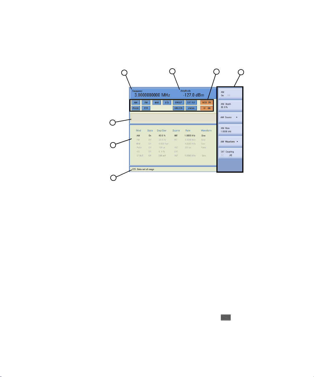
1 Frequency Area displays the current CW (continuous wave)
frequency.
2Amplitude Areadisplays the current output power level.
3 Annunciators display the status of most of the signal
generator functions, as well as indicating errors generated.
An annunciator position may be used by more than one
function.
•
FM becomes active when FM is enabled.
• AM becomes active when an AM is enabled.
• ARMED becomes active when a sweep mode is selected
and the signal generator is waiting for a trigger to initiate
sweeping.
• ERR becomes active when an error is generated. This
annunciator will not turn off until you have viewed all the
error messages and cleared the error queue. You can
access error messages by pressing >
Utility
Error Info.
N9310A User’s Guide 7
Page 14
1Overview
• EXT REF becomes active when an external frequency
reference is applied.
• FM becomes active when an FM is enabled.
• I/Q becomes active when an I/Q modulation is enabled.
• MOD ON/OFF indicates if the RF carrier is modulated or
not ( indicates the modulator is enabled, while
indicates disabled). Either state is always visible on the
screen.
• PULSE becomes active when a pulse modulation is
enabled.
• RF ON/OFF indicates whether the RF output is enabled
or disabled. Either state is always visible in the display.
• SWEEP becomes active when the signal generator is
sweeping.
• UNCAL becomes active when the signal generator is
unable to maintain the correct level.
• UNLOCK becomes active when any of the phase locked
loops are unable to maintain phase lock. To view further
descriptions, please refer to “Instrument Messages” on
page 163.
4Softkey Labeldisplays submenus of each function. The
content of softkey labels change according to the function
selected. Refer to Chapter 4, “Key Reference,” starting on page
53 for further information.
5 Message Area displays abbreviated system messages. When
multiple system messages occur, only the most recent
message is displayed. Press >
Utility
Error Info to view all
reported system messages along with details.
6Status Areadisplays state information about the signal
generator, such as the modulation status, sweep status, and
file catalogs and storages.
7 Active Function Area displays the current active function. For
example, if you press hardkey, the frequency is active
Frequency
and the current frequency setting is displayed.
8 N9310A User’s Guide
Page 15

Rear Panel Overview
Overview 1
11
VGA OUTPUT
DEV
10
REF IN
MOD IN
I IN
1V RMS
MAX
Q IN
PULSE MO D IN
REF OUT
HOST
TRIG IN
9
8
6
7
5
4
HIPOT PASS
3
12
N9310A N9310A-CFG002
SER:CN*********
100W MAX
Made in China
LIN E:
100-240V
50-60Hz
1
2
1Power switchThe power switch isolates the signal generator
from the AC line power. After switching on this switch, the
signal generator enters into standby and the orange standby
LED on the front panel is turned on.
2 AC power receptacle The power receptacle accepts a three- pin
plug.
3 USB Host connector Used for connecting with a controller,
such as a PC.
4 TRIG IN connector Female BNC connector, accepts a TTL
signal for triggering an sweep. Triggering occurs on either
the positive or negative edge. The frequency of the external
trigger source is no greater than 100 Hz. The damage level is
+10 V or –4 V.
≥≤
5 REF OUT connector Female BNC connector is for a output of
the internal reference frequency, which has a nominal output
level greater than 0.35Vrms, and an output impedance of 50
ohm.
N9310A User’s Guide 9
Page 16

1Overview
1
NOTE
6 REF IN connector
+20 dBm signal from an external reference oscillator that is
within ppm. The nominal input impedance is 50 ohm.
The connector accepts 2MHz, 5MHz, 10 MHz signal according
to your selection.
7 PULSE MOD IN connector This BNC input connector accepts a
TTL signal for pulse modulation. The damage level is 5 Vrms.
8 MOD IN connector This BNC input connector accepts a
1.0 +
For all these modulations, +1.0 Vpeak produces the indicated
deviation or depth. The damage level is 5 Vrms.
9 Q IN connector This female BNC input connector accepts an
external quadrature- phase component of an I/Q baseband
signal. The signal level is = 0.5 Vrms for calibrated
output level. The input impedance is 50 Ohm. The damage
level is 1 Vrms.
10 I IN connector This female BNC input connector accepts an
externally
It has the same characters with the Q baseband signal.
±
2% V (peak) signal for AM, FM, and phase modulation.
in-phase component of an I/Q modulation signal.
Female BNC connector, accepts a –3.5 to
2
I2Q
+
The I/Q IN connector is just available for external I/Q signal input
with the Option 001.
11 VGA connector connects to an external monitor or projector.
12 USB device connectors connect with external USB devices,
such as a USB memory stick.
10 N9310A User’s Guide
Page 17
Front and rear panel symbols
The signal generator has the following symbols. Before operation,
familiarize yourself with each marking and its meaning.
The instruction manual symbol: indicates that the user must refer to specific instructions in the manual.
The CE mark: a registered trademark of the European Community.
Overview 1
ISM1-A
C
US
ICES/NMB-001
N10149
shows that this is an Industrial Scientific and Medical Group 1 Class
A product. (CISPR 11, Clause 4)
The CSA mark: a registered trademark of the Canadian Standards
Association International.
The ISM device complies with Canadian Interference- Causing
Equipment Standard- 001.
Cet appareil ISM est conforme à la norme NMB- 001 du Canada.
The C-Tick Mark: a trademark registered to the Australian
Communication Media Authority. It indicates compliance with all
Australian EMC regulatory information.
marks the “on” position of the power line switch.
marks the “standby” position of the power line switch.
indicates that the instrument requires AC power input.
N9310A User’s Guide 11
Page 18

1Overview
This product complies with the WEEE Directive(2002/96/EC)
marking requirements. The affixed label indicates that you must not
discard this electrical/electronic product in domestic household
waste.
Product Category: With reference to the equipment types in the
WEEE Directive Annex 1, this product is classed as a Monitoring
and Control instrumentation product.
Do not dispose in domestic household waste. To return unwanted
products, contact your local Agilent office, or see
http://www.agilent.com/environment/product/
12 N9310A User’s Guide
Page 19

Agilent N9310A RF Signal Generator
User’s Guide
2
Getting Started
Check the Shipment and Order List 14
Safety Notice 16
Environmental Requirements 17
Electrical Requirements 18
Power on and Check 21
Some Tips 24
Connectors Maintenance 27
This chapter gives you the information you will need, in
most cases, to configure connections to your instruments
and interfaces and start using the signal generator properly.
s
13
Page 20

2 Getting Started
Check the Shipment and Order List
As you receive the shipment, please refer to the following
procedures, check the shipment and your order list . If your
doubted about the shipment, please contact Agilent
Technologies Customer Contact Center for consultation and
service.
✔ Inspect the shipping container for damage.
Signs of damage may include a dented or torn shipping
container or cushioning material that indicates signs of
unusual stress or compacting.
✔ Carefully remove the contents from the shipping container
and verify that your order is complete. Each shipment
includes the following items as standard:
Item Quantity Part Number
N9310A signal generator 1 N9310A
USB cable 1 8121-1482
Three-pin power cord 1 Specific to region
Quick Start Guide 1 N9310-90003
User’s Guide 1 N9310-90001
Help kit CD-ROM 1 N9310-84500
Calibration certificate 1 N/A
✔ If you ordered any of the following options, verify if they
are in the shipment by checking the product label on the
rear panel and the package checking list.
Option Name Part number
001 I/Q modulator N9310A-001
1CM Rackmount flange kit N9310A-1CM
1TC Hard transit case N9310A-1TC
14 N9310A User’s Guide
Page 21

Rack Mount
Getting Started 2
You are recommended to rackmount flange kit (option 1CM)
to install the signal generator into a rack.
Do not attempt to rack mount the signal generator by the
front panel handles only. This rackmount kit allows you to
mount the signal generator with or without handles.
CAUTION
Tra ns it
Installing the signal generators into other racks may promote shock
hazards, overheating, dust contamination, and inferior system
performance. Consult your Agilent customer engineer about
installation, warranty, and support details.
You are also recommended to use the hard transit case
(option 1TC) for instrument transportations.
N9310A User’s Guide 15
Page 22

2 Getting Started
Safety Notice
Please read the following warnings and cautions carefully
before you power on the signal generator to ensure your
personal and instrumental safety.
WARNING
WARNING
WARNING
CAUTION
CAUTION
Always use a well-grounded, three-pin AC plug and power cord to
connect to a power source. Personal injury may occur if there is any
interruption of the AC power cord of the signal generator. Intentional
interruption is prohibited.
Personal injury may result if the signal generator covers are removed.
There are no operator service parts inside. To avoid electrical shock,
refer servicing to qualified personnel.
Electrical shock may result if the signal generator is connected with
the power supply when cleaning. Do not attempt to clean internally.
Installing the signal generator in other racks may promote shock
hazards, overheating, dusting contamination, and inferior system
performance. Consult to your Agilent customer engineer about
installation, warranty, and support details.
Damage to the signal generator may result when the total power
dissipated in the cabinet is greater the 800 watts. When this condition
exists, forced convection must be applied.
CAUTION
16 N9310A User’s Guide
Avoid turning off the signal generator when current state is changing
as a result of front panel operation or remote control.
Page 23

Environmental Requirements
Agilent Technologies has designed this product for use in
Installation Category II, POLLUTION DEGREE 2, per IEC
61010- 1. Agilent has designed the signal generator for use
under the following conditions:
•Indoor use
• Altitude < 3,000 meters
• Temperature 0 to 45
• 15% to 95% relative humidity for temperatures at 40
Ventilation
Ventilation holes are located on the rear panel and all four
sides of the signal generator cover. Do not allow these holes
to be obstructed, as they allow air flow through the signal
generator.
When installing the signal generator in a cabinet, do not
restrict the convection into and out of the signal generator.
The ambient temperature outside the cabinet must be less
than the maximum operating temperature of the signal
generator by 4
cabinet.
Getting Started 2
o
C, unless otherwise specified
o
C
o
C for every 100 watts dissipated within the
Cleaning Tips
To prevent electrical shock, disconnect the signal generator
from mains before cleaning. Use a dry cloth or one slightly
dampened with water to clean the external case parts. Do
not attempt to clean internally.
WARNING
Electrical shock may result if the signal generator is connected from
the power supply while cleaning. Do not attempt to clean internally.
N9310A User’s Guide 17
Page 24

2 Getting Started
Electrical Requirements
The signal generator has an auto- ranging line voltage input.
The available AC power source must meet the following conditions:
Voltage: 100~240 volts nominal
Frequency:50/60 Hz nominal
Power: 100 watts maximum
Connecting the AC Power Cord
This is a Safety Class I Product provided with a protective
earth ground incorporated into the power cord. The front
panel switch is only a standby switch; it is not a power
switch. The AC power cord is the disconnecting device that
disconnects the signal generator mains circuits from the
mains supply. Alternatively, The rear panel switch or circuit
breaker may also be used as a disconnecting device.
Perform the following steps to connect the AC power cord:
✔ Ensure that the power cord is not damaged.
✔ Install the signal generator so that you can easily reach
the AC power cord or circuit breaker.
✔ Insert the main plug into a socket outlet provided with a
protective earth grounding.
18 N9310A User’s Guide
Page 25

AC Power Cord Localization
Getting Started 2
Plug Type
250V 10A
250V 10A
250V 10A
125V 12A
250V 10A
a. Plug identifier numbers describe the plug only. The part number is for the complete cable assembly.
Cable Part
Number
8121-1466 BS 1363/A Option 900
8120-1454 KS C8305 Option 902
8120-1378 CNS 10917-2 Option 903
8120-4754 JIS C8303 Option 918
8120-8377 GB 1002 Option 922
a
Plug
Description
For Use in
Country & Region
United kingdom, Hong Kong,
Singapore, Malaysia
Korea
Ta iw a n
Japan
China
N9310A User’s Guide 19
Page 26

2 Getting Started
Electrostatic Discharge Protection
Electrostatic discharge (ESD) damages or destroys electronic
components (the possibility of unseen damage caused by
ESD is present whenever transportation, store or use of
components).
This product contains components that are easily damaged
by Electrostatic Discharge (ESD). To help reduce ESD
damage that can occur while using test equipment:
1 Each day, before connecting any coaxial cable to the signal
generator connector for the first time, momentarily short the
center and outer conductors of the cable together.
2 Before touching the center pin of any connector, and before
removing any assembly from the signal generator, ground
users with a 1 MW resistor- isolated wrist- strap.
3 Be sure that all instruments are properly grounded to
prevent build- up of static charge.
For more information about ESD and how to prevent ESD
damage, contact the Electrostatic Discharge Association
(http://www.esda.org). The ESD standards developed by this
agency are sanctioned by the American National Standards
Institute (ANSI).
20 N9310A User’s Guide
Page 27
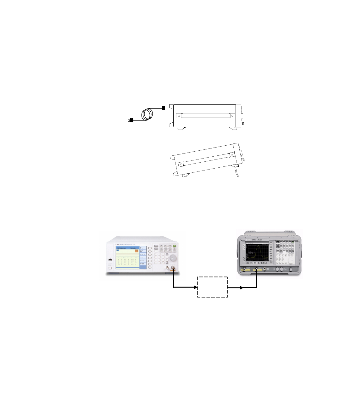
Power on and Check
1 Connect the power cord. Insert the plug into a power socket
2 Connect a cable to the output connector of the signal source
Getting Started 2
provided with a protective earth. Set the tilt adjustor for
your preference.
and then connect the cable to your DUT (device under test).
DUT
N9310A User’s Guide 21
Page 28
2 Getting Started
Turn On the Signal Generator
1 Toggle the line switch to on the rear panel to On state.
The orange standby LED will light and the signal generator
has connected with the AC line power.
2 Press the standby switch on the front panel. The green
Switch On LED will light and the signal generator boots up.
Self- initialization takes about 30 seconds, including self- test.
If it detects an error, it reports an error message. The signal
generator then defaults to a maximum frequency of 3 GHz
and a minimum amplitude of –127 dBm, then the signal
generator is ready for your current use. After power on, let
the signal generator warm up for 45 minutes for
stabilization.
NOTE
22 N9310A User’s Guide
The front panel switch is a standby switch only; it is not a power switch.
To disconnect the signal generator from the line power, turn off the power
switch on the rear panel.
Page 29

Check for Error Messages
The signal generator has two categories of instrument
messages: system messages and error messages. A system
message is triggered by operation errors, for example, setting
conflicts or data input is out of the range of a parameter.
An error message mainly is triggered by hardware defects
and has an ERR annunciator displaying on the screen.
In condition of a operation error occurs, the signal generator
reports a message at the bottom of the screen, indicating an
operation error occurred and the instrument has corrected
the error. The signal generator also automatically clears the
system messages 30 seconds later.
In condition of hardware defects or system error occurs, the
signal generator reports a message at the bottom of the
screen and also has an ERR annunciator displaying.
Here are some tips for you to check the signal generator for
error messages.
1 Check the display to see if the ERR annunciator is displayed.
If it is, press >Error Info to review each error messages in
the queue. Please refer to Chapter 7, “Instrument Messages”
for detailed system messages descriptions.
Utility
Getting Started 2
2 When you have reviewed and resolved all of the error
messages, press > Error Info > Clear softkey to delete the
Utility
messages.
3 Cycle the power on the signal generator and then check
again if the ERR annunciator is still there.
4 If you can not resolve all error messages, please contact
Customer Contact Center for service.
N9310A User’s Guide 23
Page 30

2 Getting Started
Some Tips
Refer to the following hints to set up the signal generator for
your preference. For more detailed description, see
“Utility” on page 81.
• Set the screen saver on by pressing
Utility
> Screen Saver> On
With the screen saver set to On, the display light turns off
after 15 minutes with no input from the front panel. The
display light turns on when pressing any front panel key.
• Select a display style by pressing
Utility
> Display Style
NOTE
The display style and the screen saver are persistent state, pressing
Preset
• Toggle the phase noise mode by pressing
• Save the current configures for your frequent use to
either local memory or an external USB memory
• Connect and set an external reference by pressing
• Connect an external display monitor to the VGA
connector for the education projects or other needs.
Enable an option
You are required to enter the option license key to enable
the option. Contact your nearest Agilent Office for
purchasing a license. Refer to the following steps to enable
the I/Q modulator (option 001):
1 Press hardkey
2 Press License key softkey
3 Enter the license and the option will be enabled immediately
hardkey will not affect these settings.
Utility
> Opti. F Noise> Normal/ResFM Opt.
Utility
> Ref Setups
Utility
24 N9310A User’s Guide
Page 31

Remote Control
The configuration of setting up a remote control for your
N9310A is simply. You only need find a USB cable to
connects your N9310A with a PC which has installed Agilent
IO Libraries Suite.
If you need the remote control more flexible, you can also
build up your own program by using Agilent VTL (Visa
Transition Library and the SCPI commands.
Getting Started 2
For more information about N9310A SCPI commands and
programming examples, refer to “Subsystem Command
Reference” on page 101.
For more information about Agilent IO Libraries Suite, refer
to http://www.agilent.com/find/iolib
If you are new to instrument programming, please refer to
Chapter 5, “Programming Fundamentals,” starting on page 85.
N9310A User’s Guide 25
Page 32

2 Getting Started
Firmware Update
Agilent Technologies provides convenient firmware update
service. Please refer to http://www.agilent.com/find/n9310a/ for
firmware download.
Follow this procedure to finish the firmware update:
1 Download the firmware update package to the root directory
of your USB memory stick. Do not put this package into any
other folders when updating.
3 Insert this USB memory device into the USB connector
(DEV) of the signal generator
4 Power on your signal generator, the instrument will perform
the update process automatically.
After this procedure, you will get your signal generator with
latest version firmware. Press > Information to view the
current firmware version of your signal generator.
26 N9310A User’s Guide
Utility
Page 33

Connectors Maintenance
Check the connectors at least every six months—more often
if the instrument is used daily on a production line or in a
harsh environment.
Visually inspect the front panel connectors. The most important connectors are those to which the DUT (device under
test) is connected, typically the RF cable end or the RF OUT
and LF OUT connectors. All connectors should be clean and
the center pins centered. The fingers of female connectors
should be unbroken and uniform in appearance. If you are
unsure whether the connectors are good, gauge the RF OUT
connectors to confirm that their dimensions are correct.
Maximum and minimum protrusion of center conductor from mating plane
Getting Started 2
Min. = 0.204 in. Max = 0.207 in.
Mating plane
N9310A User’s Guide 27
Page 34

2 Getting Started
28 N9310A User’s Guide
Page 35

Agilent N9310A RF Signal Generator
User’s Guide
3
Using Functions
Commonly used Front-panel Elements 30
Generating a CW Signal 32
Generating a Step Swept Signal 33
Generating a Modulated Signal 40
Generating an LF Output 48
Save, Recall and Delete an Instrument State 49
This chapter contains procedures that show you how to use
some of the major functions of your signal generator including setting frequency and power levels, setting up modulations, creating RF and LF sweeps, saving and recalling
instrument states, and enabling options.
29
Page 36

3Using Functions
Commonly used Front-panel Elements
Besides using basic function hardkeys, you will be also busy
with entering data and using softkeys. If you are new to
N9310A, refer to the following tips on entering data and
using softkeys.
Entering Data
When setting the value for a parameter, there are two ways
of entering or modifying the value of the active function:
Using the numeric keypad and the unit softkey
Numeric Keypad Enters a specific value.
Unit softkey Terminates a data input via the numeric keypad
Using the knob, arrow keys and the Enter hardkey
Knob Increases or decreases the value or the value of each digit
Arrow Keys Set focus on the digit to be modified
Enter Confirms and terminates the data input
30 N9310A User’s Guide
Page 37

Using Softkeys
Softkeys, which appear along the right side of the display,
provide access to many sub- functions. There are three types
of softkeys being used in N9310A. See the table below to
learn their types and functions.
Ty pe F un ct io n E xa m pl e
Using Functions 3
To g g le
Submenu
Modify
Presses this types of softkeys toggles a
parameter between two states
Presses this types of softkeys enters into a
submenu
Presses this types of softkeys enables you to
modify the value of a parameter
N9310A User’s Guide 31
Page 38

3Using Functions
Generating a CW Signal
Generating a CW (Continuous Wave) signal requires you to
set up the frequency and amplitude parameters and enable
the RF output. The parameters has the following characters:
Character Range Default
Frequency 9 kHz to 3 GHz 3.0000000000 GHz,
with 0.1 Hz resolution
Amplitude –127 to +13 dBm (+20 dBm settable)
–80 to +60 dBmV (+67 dBmV settable)
–20 to +120 dBμV (+127 dBμV settable)
0.0001 to 1000 mV (2238.8 mV settable)
0.1 to 1000000 μV (2238800 μV settable)
–127 dBm,
with 0.1 dB resolution
Operation Example
Assume you need to generate a CW signal with:
• a frequency of 700 MHz
• an amplitude of –20 dBm
Please refer to the following steps to set up the CW signal:
Preset
1 Press
This returns the signal generator to the factory default state.
To view the default settings of the signal generator, please
check “Factory Default Settings” on page 70
Observe the FREQUENCY and AMPLITUDE area of the display
(in the upper left- hand corner). The value displayed is the
maximum frequency (3 GHz) and the minimum amplitude
(–127 dBm)
2 Press > 700 > MHz sets the CW frequency to 700 MHz.
hardkey
.
Frequency
3 Press > – 20 > dBm sets the CW amplitude to –20 dBm.
4 Toggle hardkey to enable the RF output.
Amplitude
RF
On/Off
32 N9310A User’s Guide
Page 39

Generating a Step Swept Signal
The signal generator allows you to generate step swept
signals in three modes:
Sweep Mode Sweep Range Front-panel key access
Using Functions 3
NOTE
RF 9 kHz to 3 GHz > Sweep Mode > RF
Amplitude –127 to +13 dBm > Sweep Mode > Ampl
LF 20 Hz to 80 kHz > Sweep Mode > LF
Sweep
Sweep
Sweep
During the swept RF output or Amplitude output, the FREQUENCY and
AMPLITUDE area of the signal generator’s display are deactivated,
depending on which is being swept.
General Settings for a Step Sweep
Generally, you need to set up the following parameters for a
step sweep:
• the start frequency/amplitude and stop
frequency/amplitude
• a number of equally spaced points (steps) to dwell upon
• the amount of dwell time at each point
For an intuitive view of how to generate a sweep, please
refer to:
“Generating an RF Sweep” on page 36,
“Generating an Amplitude Sweep” on page 38,
“Generating an LF Sweep” on page 39.
N9310A User’s Guide 33
Page 40

3Using Functions
Additional Settings for a Step Sweep
There are also other four setting items that have effects on
the sweep:
• Sweep Trigger
You can set the sweep trigger to any of the following
three choices: Immediate/Trigger Key/EXT
• Point Trigger:
You can set the point trigger to any of the following three
choices: Immediate/Trigger Key/EXT
• Sweep Repeat: Cont/Single
You can set the sweep repeat to either Cont or Single.
If set to Cont, the signal generator sweeps from the start
point to the stop point and cycles continuously.
If set to Single, the signal generator sweeps from the start
point to the stop point for only one circle.
• Sweep Direction: Up/Down
Take RF sweep for example, as you enable RF sweep by
pressing
Sweep
> Sweep Mode > RF, the signal generator performs as
below, according to combinatorial settings of sweep trigger
and point trigger.
Sweep
Trigger
IMM IMM Pressing >Sweep mode > RF initiates sweeping immediately and
IMM Key Pressing >Sweep mode > RF enables the RF sweep, then
Point
Trigger
Sweep Performance
Sweep
automatically. Pressing >Sweep mode >Off closes the sweep.
Sweep
pressing the Trig g e r ke y initiates sweeping over the points
manually.
Sweep
34 N9310A User’s Guide
Page 41

Using Functions 3
Sweep
Trigger
Point
Trigger
Key IMM
Key Key
Sweep Performance
Pressing >Sweep mode > RF, the "ARMED" annunciator displays
on the screen, indicating the signal generator is ready and waits
for your trigger instruction. Pressing Trigger key initiates the signal
generator sweeping over the points automatically.
Pressing >Sweep mode > RF, the "ARMED" annunciator displays
on the screen, indicating the sweep is ready and wait for your
trigger.
Pressing >Sweep mode > RF enables the RF sweep, then
pressing the Trig g e r ke y initiates sweeping over the points
manually.
Sweep
Sweep
Sweep
If you want to use an external trigger source, a TTL signal
with 100 ns as the minimum level holding time is required.
Only when the sweep trigger is set to Key and the point
trigger is set to EXT, is the sweep repeat able to set to either
Single or Cont. The other combinations of the sweep trigger
and point triggers allows continuous sweep only.
N9310A User’s Guide 35
Page 42

3Using Functions
Generating an RF Sweep
Assume you are going to generate an RF sweep with the following settings:
• frequency range from 1 GHz to 2 GHz, at a level of 0
dBm
• nine sweep points and 50 ms dwell time at each point
Refer to the following procedures to configure and generate
an RF sweep:
1 Press
2 Press
Preset
hardkey
Amplitude
> 0 > dBm
This step sets the RF sweep output level at 0 dBm.
3 Press hardkey
Sweep
This step opens the sweep submenus.
4 Press Step Sweep softkey
This step opens a submenu for step sweep configurations.
5 Press RF Start > 1 > GHz
This step sets the start frequency of the sweep to 1 GHz.
6 Press RF Stop > 2 > GHz
This step sets the stop frequency of the sweep to 2 GHz.
7 Press # Points > 9 > Enter
This step sets the number of sweep points to nine.
8 Press More(1/2) > Step Dwell > 50 > ms
This step sets the dwell time at each point to 50 ms.
9 Press hardkey to enable the RF output.
RF
On/Off
The annunciator changes from to .
36 N9310A User’s Guide
Page 43

Using Functions 3
10 Press Return > Sweep Mode > RF
This step enables the RF sweep and initiates the signal
generator to sweep immediately and automatically. A SWEEP
annunciator displays for the duration of the sweep.
NOTE
The signal generator defaults the sweep trigger and point
trigger settings to Immediate as you preset the instrument.
For more information about how to use different trigger
modes, please refer to “Additional Settings for a Step
Sweep” on page 34.
For more information about the sweep settings, please refer
to “Sweep” on page 73.
N9310A User’s Guide 37
Page 44

3Using Functions
Generating an Amplitude Sweep
Assume you are going to generate an amplitude sweep with
the following settings:
• amplitude ranges from –80 to –60 dBm, at a frequency of
1 GHz
• 9 sweep points and 50 ms dwell time at each point
Refer to the following steps to configure and generate an
amplitude sweep:
Preset
1 Press
hardkey
2 Press
3 Press hardkey
Frequency
Sweep
> 1 > GHz
4 Press Step Sweep softkey
5 Press Ampl Start > –80 > dBm
6 Press Ampl Stop > –60 > dBm
7 Press # Points > 9 > Enter
8 Press More(1/2) > Step Dwell > 50 > ms
9 Press hardkey to enable the RF output.
RF
On/Off
10 Press Return > Sweep Mode > Ampl to enable the amplitude
sweep immediately. A SWEEP annunciator displays for the
duration of the sweep.
For more information about the sweep settings, please refer
to “Sweep” on page 73.
38 N9310A User’s Guide
Page 45

Generating an LF Sweep
Assume you are going to generate an LF sweep with the following settings:
• frequency range from 10 to 60 kHz, at a level of 500 mV
• six sweep points and 50 ms dwell time at each point
Using Functions 3
NOTE
Pressing sets the sweep/point trigger to Immediate and the LF
Preset
output amplitude to 500 mV. The following procedures leave out the steps
that set up the sweep/point trigger and the LF output amplitude.
Refer to the following procedures to configure and generate
an LF sweep:
Preset
1 Press
2 Press hardkey
hardkey
Sweep
3 Press Step Sweep softkey
4 Press LF Start > 10 > kHz
5 Press LF Stop > 60 > kHz
6 Press # Points > 6 > Enter
7 Press Step Dwell > 50 > ms
8 Press Return > Sweep State > LF
This initiates the LF sweep output immediately via the LF
OUT connector. A SWEEP annunciator displays for the
duration of the sweep.
For more information about the sweep settings, please refer
to “Sweep” on page 73.
N9310A User’s Guide 39
Page 46

3Using Functions
Generating a Modulated Signal
The signal generator allows you to generate the following
modulated signals: AM, FM, FM, Pulse Modulation. An
optional I/Q modulator is also available when you installed
Option 001 on the signal generator.
Preparing the Modulation Format
You can turn on the modulation format prior to or after setting the other modulation parameters. Perform the following
steps to turn the modulation format on and output a modulated signal:
1 Access the submenu a modulation format. For example, AM.
This submenu shows a set of softkeys associated with the
format’s name. For example, AM Depth, AM Source.
2 Press the hardkey until is displayed. And press
RF
key to enable the RF output.
On/Off
Mod
On/Off
AM processed and
output enabled
AM
submenu
AM
enabled
More intuitive examples on generating a modulated signal
come in the following pages.
40 N9310A User’s Guide
Page 47

Using Functions 3
Simultaneous Modulations
The signal generator also allows you to generate more than
one modulation formats simultaneously. Refer to the
following table to generate the simultaneous modulations.
AM (INT)
AM (EXT)
I/Q
FM (INT)
FM (EXT)
FM
Pulse (INT)
Pulse (EXT)
“–” :unavailable
:available
“”
AM
(INT)
AM
(EXT)
I/Q FM
(INT)
FM
(EXT)
FM Pulse
(INT)
Pulse
(EXT)
– ✔ – ✔✔✔––
✔ –– ✔✔✔––
–––✔✔✔✔✔
✔✔✔– ✔ – ✔✔
✔✔✔––– ✔✔
✔✔✔––– ✔✔
–– ✔✔ ✔ ✔––
–– ✔✔ ✔ ✔––
N9310A User’s Guide 41
Page 48

3Using Functions
Generating an AM signal
The signal generator generates AM (amplitude modulated)
signals with the following basic settings:
Character Range Default
AM Depth 0.0 to 100.0 % 0.0
AM Source Internal source (INT)
External source (EXT)
Combined INT and EXT
AM Rate 20 Hz to 80 kHz (INT)
DC/20 Hz to 80 kHz (EXT)
INT
1.0000 kHz, 0.1 Hz resolution
Operation Example
Assume that you are going to generate an AM signal with:
• Carrier frequency of 1 GHz, amplitude of –10 dBm
• AM depth of 70 %
• AM rate at 15 kHz
• Internal AM source (default by )
Refer to the following to configure your signal generator:
1 Pressing presets the signal generator
2 Pressing
3 Pressing
4 Pressing enters the AM submenu
Preset
Frequency
> 1 > GHz sets the CW frequency to 1 GHz
Amplitude
> –10 > dBm sets the CW amplitude to –10 dBm
AM
5 Pressing AM Depth > 70 > % sets AM depth to 70 %
Preset
6 Pressing AM Rate > 15 > kHz sets AM rate to 15 kHz
7 Pressing AM On enables AM
8 Pressing On enables the AM signal output
For key reference, please refer to
RF
On/Off
“A M” on page 54.
42 N9310A User’s Guide
Page 49

Generating an FM Signal
The signal generator generates FM (frequency modulated)
signals with the following basic settings:
Character Range Default
FM Deviation 20 Hz to 100 kHz 20 Hz, 1 Hz resolution
Using Functions 3
FM Source Internal source (INT)
External source (EXT)
Combined INT and EXT
FM Rate 20 Hz to 80 kHz (INT)
DC/20 Hz to 80 kHz (EXT)
INT
1.0000 kHz, 0.1 Hz resolution
Operation Example
Assume that you are going to generate an FM signal with:
• Carrier frequency of 1 GHz, amplitude of –10 dBm
• FM deviation of 50 kHz
• FM rate at 30 kHz
• Internal FM source (default by )
Refer to the following to configure your signal generator:
1 Pressing presets the signal generator
2 Pressing
3 Pressing
4 Pressing enters the FM submenu
Preset
Frequency
> 1 > GHz sets the CW frequency to 1 GHz
Amplitude
> –10 > dBm sets the CW amplitude to –10 dBm
FM
5 Pressing FM Deviation > 50 > kHz sets FM deviation to 50 kHz
6 Pressing FM Rate > 30 > kHz sets FM rate to 30 kHz
Preset
7 Pressing FM > On enables FM
8 Pressing hardkey to RF On enables FM signal output.
RF
On/Off
For key reference, please refer to “FM” on page 61.
N9310A User’s Guide 43
Page 50

3Using Functions
Generating a Phase Modulated Signal
The signal generator generates phase modulated (FM)
signals with the following basic characters:
Character Range Default
FM
Deviation
FM Source Internal source only N/A
FM Rate 300 Hz to 80 kHz 1.0000 kHz, with
0 to 10 rad (300 Hz < FM rate < 10 kHz)
0 to 5 rad (10 kHz < FM rate <
80 kHz)
0.000 rad, with
0.001 rad resolution
0.1 Hz resolution
Operation Example
Assume that you are going to generate a FM signal with the
following characters:
• Carrier frequency of 1 GHz, amplitude of –10 dBm
• FM deviation of 7.3 rad
• FM rate at 10 kHz
Refer to the following to configure your signal generator:
1 Pressing presets the signal generator
2 Pressing
3 Pressing
4 Pressing enters the FM submenu
5 Pressing FM Deviation > 7.3 > rad sets FM deviation to 7.3 rad
Preset
Frequency
> 1 > GHz sets the CW frequency to 1 GHz
Amplitude
> –10 > dBm sets the CW amplitude to –10 dBm
FM
6 Pressing FM Rate > 10 > kHz sets FM rate to 10 kHz
7 Pressing FM On off enables FM
8 Pressing RF On/Off to On enables FM signal output.
For key reference, please refer to “Phase Modulation” on
page 67.
44 N9310A User’s Guide
Page 51

Generating a Pulse Modulated Signal
The signal generator generates pulse modulated signals with
the following characters:
Character Range Default
Using Functions 3
Pulse Source Internal source (INT)
External source (EXT)
Pulse Period 200 μs to 2 s (INT and EXT) 200 ms, with 1 ms resolution
Pulse Width 100 μs to 1 s (INT and EXT) 100 ms, with 1 ms resolution
INT
Operation Example
Assume that you are going to generate an pulse modulated
signal with the following characters:
• Carrier frequency of 1 GHz, amplitude of –10 dBm
• Pulse period of 10 ms
•Pulse width of 6 ms
• Internal pulse source (default by )
Refer to the following to configure your signal generator:
1 Pressing presets the signal generator
2 Pressing > 1 > GHz sets the CW frequency to 1 GHz
3 Pressing
4 Pressing enters the Pulse modulation submenu
Preset
Frequency
Amplitude
> –10 > dBm sets the CW amplitude to –10 dBm
Pulse
5 Pressing Pulse Period > 10 > ms sets pulse period to 10 ms
Preset
6 Pressing Pulse width > 6 > ms sets pulse width to 6 ms
7 Pressing Pulse On/Off enables pulse modulation
8 Pressing On enables pulse modulated signal output
RF
On/Off
For key reference, please refer to “Pulse” on page 71.
N9310A User’s Guide 45
Page 52

3Using Functions
Generating an I/Q Modulated Signal (Option 001 Only)
The signal generator generates I/Q modulated signals with
the following basic characters:
Character Range Default
I/Q Source External source only N/A
I/Q Input 50 W impedance
N/A
VSWR < 1.5
Full scale input < 0.5 Vrms
I/Q Input Connector EXT I and Q connector on
N/A
rear panel (BNC type, female)
If you use a constant sum vector modulation of = 0.5
I2Q2+
V to drive the I/Q modulator, the actual RF level
corresponds to the displayed RF level. To avoid overdriving
the I/Q modulator, you must take care that the sum vector
never exceed 0.5 V when using I/Q modulation. For full- scale
input, the peak envelope power of the modulated RF signal
is thus equal to the indicated LEVEL. The average power is
smaller.
2Q2
I
+
Amplitude = input value LEVEL
Q
I IN
I
Q IN
---------------------
0.5V
VGA OUTPUT
N9310A N9310A-CFG002
SER:CN******* **
DEV
MOD IN
REF IN
1V RMS
MAX
PULSE MOD IN
REF OUT
HOST
Made in Chin a
TRIG IN
LINE:
100-240V
50-60Hz
100W MAX
HIPOT PAS S
46 N9310A User’s Guide
Page 53

Using Functions 3
Operation Example
Assume that you are going to generate an I/Q modulated
signal with 1 GHz carrier frequency, amplitude of –10 dBm
Refer to the following procedures to configure and generate
an I/Q modulated signal:
1 Connecting the external I/Q source to the BNC I and Q
connectors on the rear panel of the signal generator
2 Pressing presets the signal generator
3 Pressing > 1 > GHz sets the CW frequency to 1 GHz
4 Pressing > –10 > dBm
5 Pressing enters the I/Q modulation submenu
Preset
Frequency
Amplitude
I/Q
sets the CW amplitude to –10 dBm
6 Pressing I/Q On/Off enables I/Q modulation
7 Pressing enables I/Q modulated signal output
RF
On/Off
N9310A User’s Guide 47
Page 54

3Using Functions
Generating an LF Output
The signal generator allows you to generate an LF (Low
Frequency) signal with the following characters. Low
frequency signal is also usually called audio frequency.
Character Range Default
Frequency 20 Hz to 80 kHz 1.0000 kHz, with 0.1 Hz resolution
Amplitude 0 to 3 V (peak) 500 mV, with 1 mV resolution
Output
Connection
LF OUT connector on the
front panel (BNC type, 50 W)
N/A
Operation Example
Assume you are going to generate an LF signal with:
• a frequency of 10 kHz
•an amplitude of 3 V
Refer to the following steps to generate the LF signal:
1 Pressing enters submenu of LF output function.
2 Pressing LF Out Freq > 10 > kHz
3 Pressing LF Out Ampl > 3 > V
4 Pressing LF Out On/Off to On state enables LF output.
LF Out
sets LF frequency to 10 kHz
sets LF amplitude to 3 V
48 N9310A User’s Guide
Page 55

Save, Recall and Delete an Instrument State
The signal generator allows you to save instrument states
either in local memory or to an external USB memory stick
in a format of a configuration file (*.cfg). You can also recall
those states from the local memory or an external flash
memory for a quick start of commonly used instrument
states or some particular applications’ configurations.
Using Functions 3
NOTE
Before you unplug a USB memory stick from the USB connector on the
front or rear panel of the signal generator, you are recommended to set
the file catalog to Local first.
Saving an Instrument State
All the instrument states are saved in the file format of
“<file name>.cfg” , such as “sample.cfg”.
The file name can be modified with the 26 lowercase letters
from a to z and 10 arabic numbers from 0 to 9.
The signal generator provides up to 20 files memory spaces
in the local memory.
Saving an instrument state in the local memory
Refer to the following steps to save an instrument state in
the local memory:
1 Pressing
2 Pressing
instrument state you are going to save
3 Edit the file name by rotating the knob and pressing
softkey for entering each letter or number
File
> Catalog > Local sets file catalog to local memory
Save softkey enables editing a file name for the
Next
4 Pressing
the instrument state into local memory immediately
See the example on the next page for how to editing the file
name.
N9310A User’s Guide 49
Save now softkey confirms the file name and saves
Page 56

3Using Functions
How to edit a file name Assume you need to name an
instrument state as “sample”, refer to following operations:
1 Pressing Save softkey enables editing file name and the
signal generator automatically types an “a” as the first letter.
2 Rotating the knob until the first letter changes to “s”.
3 Press Next softkey to confirm the first letter and the signal
generator automatically types an “a” as the second letter.
4 Repeat step 2 and step 3, until editing the file name
“sample” completes.
5 Pressing Save now confirms the file name and saves the
instrument state named as “sample.cfg” immediately in the
local memory.
Saving an instrument state to an external USB memory stick
Refer to the following steps to save an instrument state into
a USB memory stick:
1 Pressing Catalog
2 Pressing Save softkey enables editing file name for the
instrument state you are going to save.
3 Edit the file name by rotating the knob and pressing Next
softkey for entering next letter.
4 Press Save now softkey to confirm the file name and save the
instrument state into the external USB memory stick
immediately.
50 N9310A User’s Guide
> USB sets the file catalog to USB.
Page 57

Recalling an Instrument State
The signal generator allows you to recall an instrument state
from the either the local memory or an external USB
memory stick.
Recalling an instrument state from the local memory
Refer to the following steps to recall an instrument state
from the local memory:
1 Set file catalog to Local (default)
2 Rotate the knob to choose a file
3 Press the Recall softkey to recall the file immediately
Recalling an instrument state from an external flash memory
Refer to the following steps to recall an instrument state
from the local memory:
1 Set file catalog to USB
Using Functions 3
2 Rotate the knob to choose a file
3 Press the Recall now softkey to recall the file immediately.
Delete an Instrument State
Refer to the following steps to delete an instrument state
from the local memory:
1 Set file catalog to Local or USB
2 Rotate the knob to choose a file
3 Press the Delete softkey
4 Press the Delete now softkey to confirm and delete the file
immediately
NOTE
N9310A User’s Guide 51
It is impossible to recover files after pressing Delete now. If you change
your mind and do not wish to delete the files, press Return softkey
instead.
Page 58

3Using Functions
52 N9310A User’s Guide
Page 59

Agilent N9310A RF Signal Generator
User’s Guide
4
Key Reference
This chapter describes each front panel hardkey and
associated softkeys, as well as the default value for each key.
The chapter is organized alphabetically by front panel
hardkey. Each section arranges the softkey description
logically.
s
53
Page 60

4Key Reference
AM
AM
On/Off
AC/DC
AM
AM
Toggles amplitude modulation state between on and off
Sets amplitude modulation depth
Enters amplitude modulation source submenu:
INT
EXT
INT+EXT
Selects internal AM source
Selects external AM source
Selects internal and external AM source
Sets amplitude modulation frequency
Selects amplitude modulation waveform
Sine
Selects sine amplitude modulation waveform
Toggles external coupling between AC and DC
Pressing reveals a submenu for AM configurations.
AM Depth
AM Source
AM Rate
AM Waveform
EXT Coupling
AM On Off Pressing this softkey toggles the amplitude modulation
between on and off
. A annunciator will display on the
screen after you enable AM. However, the amplitude
modulation will be processed only when you also turn the
modulation on by pressing the hardkey.
Mod
On/Off
• Default value: Off
• Key sequence:
AM
> AM On Off
54 N9310A User’s Guide
Page 61

Key Reference 4
AM Depth Pressing this softkey enters the value of AM depth. The
active entry area displays the current value of AM depth.
The AM Depth ranges from 0 % to 100 %, with minimum
increment of 0.1 %.
• Default value: 0.0 %
• Key sequence:
AM
> AM Depth
AM Source Pressing this softkey reveals a menu of choices for amplitude
modulation sources. It allows you to select an internal
source or an external source from MOD IN connector, or
select internal and external simultaneously.
Pressing INT connects an internally calibrated signal to the
modulator. This internal AM source defaults to a sine wave
at a frequency of 1.0000 kHz.
Pressing EXT connects an externally calibrated signal to the
modulator. You need also set the EXT Coupling, see “Ext
Coupling” on next page.
Pressing INT+EXT connects both an internally calibrated
signal and an externally calibrated signal to the modulator
simultaneously.
• Default value: INT
• Key sequence:
AM
> AM Source
AM Rate Pressing this softkey modifies the internal modulation
frequency. The active entry area displays the current value
of AM rate. The allowed value range is 20 Hz to 80 kHz. The
minimum increment is 0.1 Hz. when external AM source is
selected, this softkey is disabled.
• Default value: 1 kHz
• Key sequence:
AM
> AM Rate
N9310A User’s Guide 55
Page 62

4Key Reference
AM Waveform Pressing this softkey reveals a menu of modulating signal
Ext Coupling Pressing this softkey toggles external modulating signal input
waveform choice.
• Default value: Sine
• Key sequence:
AM
> AM waveform
either in AC (Alternating Current) or DC (Direct Current)
coupling.
Selecting AC isolates the DC component in the signal and
only passes by AC component into the modulator. The
Amplitude will go down without DC component.
Selecting DC allows an integrated external signal with both
DC and AC component. A 1.0 V
peak + 2 % input level is
required.
• Default value: AC
• Key sequence:
AM
> EXT Coupling
56 N9310A User’s Guide
Page 63

Amplitude
Key Reference 4
Pressing hardkey allows you to modify the RF output
Amplitude
power level. Amplitude becomes the active function and the
active entry area of the display shows the current value.
The calibrated power range is –127 to 13 dBm (+20 dBm
settable). The minimum increment allowed is 0.1 dB. The
amplitude area of the display always shows the current RF
output power except when an amplitude sweep is in process.
• Default value: –127.0 dBm
It also allows you to modify the RF output power level using
the following scales:
Range Minimum increment
–127.0 to +13.0 dBm, (max. +20 dBm settable) 0.1 dB
–80.0 to +60.0 dBmV, (max. +67 dBmV settable) 0.1 dB
–20.0 to +120.0 dBμV, (max. +127 dBμV settable) 0.1 dB
0.0001 to 1000.0 mV, (max. 2238.8 mV settable) 0.1 mV
0.1 to 1000000.0 μV, (max. 2238800 μV settable) 0.1 μV ( Ampl < 999.9 μV)
100 μV (Ampl >
1000.0 μV)
N9310A User’s Guide 57
Page 64

4Key Reference
Arrow Keys
Pressing the left/right arrow keys allows you to modify a
data digit by digit, together with rotating the knob. You also
need pressing hardkey to confirm the data
Enter
modification.
For example, if you wish to modify 2.000 000 0000 GHz to
2.000 000 0500 GHz, please follow these steps:
1 pressing the left/right arrow key shift the focus to the digit
2 rotating the knob until “5” displays
Enter
3 Pressing hardkey to confirm your modification
There are two usages of the hardkey.
Enter
Enter
1 Confirming data modification. Using Enter hardkey together
with arrow keys or knob when modifying a data. See the
usage in Arrow Key on the same page.
2 Initiating a single sweep. Take an RF single sweep for
example, pressing
Sweep
> Sweep Mode > RF initiates the first
run of a single RF sweep, then the sweep hangs up for an
instruction to run again. Pressing hardkey at this
Enter
moment instructs the instrument to run another cycle of the
single RF sweep again.
58 N9310A User’s Guide
Page 65

File
AM
Key Reference 4
Pressing hardkey reveals a submenu for saving, or
File
recalling or deleting a customized configuration file. For how
to do with a file, you can also refer to “Save, Recall and
Delete an Instrument State”
Catalog
Save
Recall
Delete
Accesses the File Catalog submenus
Local
USB
Enables editing a file name and saving a file
Save now
Next
Recalls a file from the current catalog
Deletes a file from the current catalog
Delete now
on page 49.
Selects local memory as the current catalog
Selects USB device as the current catalog
Saves a file to the current catalog
Goes to edit next letter/number
Confirms deleting
Catalog Pressing this softkey selects the catalog for storing
configuration files. Local means saving a configuration file in
the instrument’s internal memory. USB means saving a
configuration file in a peripheral USB memory stick via the
USB device connector.
Insert the external memory stick into the USB connector
(device) first, then the signal generator detects the USB
memory stick as soon as you set the catalog to USB.
• Default value: Local
• Key sequence:
File
> Catalog
N9310A User’s Guide 59
Page 66

4Key Reference
Save Pressing Save softkey enables you to save the current
instrument status into a file and also edit a file name for
the file. You can save maximum 20 files in the local memory.
Pressing hardkey or conducting a power cycle does not
Preset
affect the customized configuration file in the local memory.
See “Saving an Instrument State” on page 49 on editing a
file name by using Save, Save now and Next softkeys.
• Softkey sequence:
File
> Save
Recall Pressing Recall softkey recalls a customized configuration file
that you have selected by scrolling the knob.
Before you press this softkey to recall a file from external
USB memory stick, make sure the file you need is in the
root directory of the USB memory stick.
• Softkey sequence:
File
> Recall
Delete Pressing Delete softkey enables you to delete a configuration
file that you have selected by rotating the knob. Pressing
Delete now confirms deleting.
• Softkey sequence:
File
> Delete
CAUTION
Do NOT press Delete now before you make sure the selected file is the
one you do not need any more.
60 N9310A User’s Guide
Page 67

FM
Key Reference 4
Pressing hardkey reveals a submenu for FM
FM
configurations.
AM
FM
On/Off
FM Deviation
FM Source
FM Rate
FM Waveform
Toggles frequency modulation between on and off
Sets frequency modulation deviation
Enters frequency modulation source submenu:
INT
EXT
INT+EXT
Selects internal FM source
Selects external FM source
Selects internal and external FM source
Sets frequency modulation rate
Selects frequency modulation waveform
Sine
Selects sine frequency modulation waveform
EXT Coupling
AC/DC
Toggles external coupling between AC and DC
FM On Off This softkey toggles the frequency modulation between on
and off. When press this softkey on, the FM annunciator is
turned on in the display. Although pressing this softkey
enables the FM, it is applied to the RF carrier only after you
also enable the modulator by pressing and the
Mod
On/Off
displays.
• Default value: Off
• Key sequence: > FM On Off
FM
N9310A User’s Guide 61
Page 68

4Key Reference
FM Deviation Pressing this softkey sets the frequency modulation
deviation. The active entry area shows the current FM
deviation. The allowed values range is 20 Hz to 100 kHz. The
minimum increment is 0.1 Hz.
• Default value: 20 Hz
• Key sequence: > FM Deviation
FM
FM Source Pressing this softkey reveals a menu for Frequency
modulation sources selection. It allows you to select an
internal FM source or an external FM source from MOD IN
connector, or select internal and external simultaneously.
Pressing INT connects an internally generated, calibrated
signal to the modulator. This internal FM source defaults to
a sine wave at a frequency of 1.0000 kHz.
Pressing EXT connects an externally calibrated signal to the
modulator. You need also set the EXT Coupling, see “EXT
Coupling” on next page.
Pressing INT+EXT connects both an internally calibrated
signal and an externally calibrated signal to the modulator
simultaneously.
• Default value: INT
• Key sequence: > FM Source
FM
FM Rate Pressing this softkey allows you to enter the frequency of
internal modulation source. The active entry area displays
the current FM rate. The allowed value range is 20 Hz to 80
kHz. The minimum increment is 0.1 Hz. When external FM
source is selected, this softkey is disabled.
• Default value: 1.0000 kHz
• Key sequence: > FM Rate
FM
62 N9310A User’s Guide
Page 69

Key Reference 4
FM Waveform Pressing this softkey reveals a submenu of FM waveform
choices.
• Default value: Sine
• Key sequence: > FM Waveform
FM
EXT Coupling Pressing this softkey toggles external modulating signal input
in either AC or DC coupling. A 1.0 V
peak + 2 % input level is
required.
Selecting AC isolates the DC component in the signal, there
is only AC component in the applied signal. The amplitude
will go down without DC component.
Selecting DC allows an integrated external signal with both
DC and AC component entering to the modulator of the
signal generator.
• Default value: AC
• Key sequence: > EXT Coupling
FM
N9310A User’s Guide 63
Page 70

4Key Reference
Frequency
Pressing hardkey allows you to modify the RF output
frequency. Frequency becomes the active function and the
active entry area displays the current value.
The allowed frequency range is 9 kHz to 3 GHz. The
minimum increment is 0.1 Hz. The frequency area always
shows the current CW output frequency except when an RF
sweep is in process.
• Default value: 3 GHz
I/Q (Option 001 only)
I/Q
On/Off
I/Q
This softkey toggles the external I/Q modulation state
On Off
between on and off. Whenever I/Q modulation is enabled,
the I/Q annunciator displays on the screen.
• Default value: Off
• Key sequence: I/Q > I/Q On Off
Frequency
Switches I/Q modulation on/off
64 N9310A User’s Guide
Page 71

LF Out
Key Reference 4
Pressing hardkey reveals a submenu of softkeys to
LF Out
configure the internal LF (low frequency) generator.
AM
LF Out
On/Off
LF Out
On/Off
LF Out Freq
LF Out Ampl
This softkey toggles the LF output between on and off. Once
you have set the output on, the signal is available at the LF
OUT connector. The and hardkeys do not apply to
Toggles LF output between on and off
Sets LF frequency
Sets LF output amplitude
Mod
On/Off
RF
On/Off
this state.
• Default value: Off
• Key sequence: > LF On/Off
LF Out
LF Out Freq Pressing this softkey sets the frequency of the LF signal. The
active entry area displays the current LF signal frequency.
The allowed frequency range is 20 Hz to 80 kHz.
• Default value: 1.0000 kHz
• Key sequence: > LF Out Freq
LF Out
LF Out Ampl Pressing this softkey sets the amplitude of the LF signal. The
active entry area displays the current LF signal amplitude.
The allowed amplitude range is 0 to 3 Vpeak, with 1 mV
minimum increment.
• Default value: 500 mV
• Key sequence: > LF Out Ampl
N9310A User’s Guide 65
LF Out
Page 72

4Key Reference
Mod On/Off
Toggle this hardkey On to modulate the RF carrier with the
active modulation.
An Mod On/Off annunciator is always turned on in the
display to indicate whether modulation is on or off.
After pressing hardkey, a
on the screen which indicates the modulator is active.
• Default value: Mod On
RF On/Off
Pressing this hardkey toggles the RF out between on and off.
An annunciator is always in the display to indicate whether
RF is on or off.
Default Value: RF Off
Numeric Keypad
The numeric keypad consists of digit keys (0 to 9), a decimal
point key, and a backspace key. The backspace key has dual
functions for backspacing and changing the sign of a value
to positive or negative. Use these keys at any time when an
active function requires a value input.
The backspace key function changes according to the
situations below:
• When modifying a previously entered value, pressing the
backspace key deletes the entire value and leaves the
negative sign. Subsequent key presses change the sign
between positive and negative states.
• When entering a new value, pressing the backspace key
deletes the digit immediately to the left. When no digit
remains, subsequent key presses change the sign between
positive and negative states.
Preset
annunciator will display
66 N9310A User’s Guide
Page 73

Phase Modulation
Key Reference 4
Pressing the hardkey reveals a submenu of softkeys for
FM
phase modulation configurations.
AM
FM
On/Off
FM Deviation
FM Source
FM Rate
FM Waveform
Toggles phase modulation between on and off
Sets phase modulation deviation
Enters phase modulation source submenu:
INT
Sets phase modulation rate
Selects phase modulation waveform
Sine
Selects internal ΦM source
Selects sine phase modulation waveform
FM On Off Pressing this softkey toggles the phase modulation between
on and off. Whenever phase modulation is enabled, the FM
annunciator is turned on in the display. However, it is
applied to the RF carrier only after you also enable the
modulator by pressing hardkey and the annunciator
Mod
On/Off
displays.
• Default value: Off
• Key sequence: > FM On/Off
FM
FM Deviation Pressing this softkey sets the phase modulation deviation.
The active entry area displays current FM deviation value.
The allowed value ranges according to the FM rate:
0 to 10 rad (300 Hz <
0 to 5 rad (10 kHz < FM rate 80 kHz)
• Default value: 0.000 rad
• Key sequence: > FM Deviation
FM rate <10 kHz)
≤
FM
N9310A User’s Guide 67
Page 74

4Key Reference
FM Waveform Pressing this softkey reveals a submenu of FM waveform
FM Source Pressing this softkey chooses a phase modulation source.
• Default value: INT
• Key sequence: > FM Source
FM
FM Rate Pressing this softkey modifies the internal modulation
frequency. The active entry area displays the current value
of FM rate. The allowed values range is 300 Hz to 80 kHz.
The minimum increment is 0.1 Hz. when external FM source
is selected, this softkey is disabled.
• Default value: 1.0000 kHz
• Key sequence: > FM Rate
FM
choices.
• Default value: Sine
• Key sequence: > FM Waveform
FM
68 N9310A User’s Guide
Page 75

Switch
Key Reference 4
N9310A RF Signal Generator 9 kHz – 3.0 GHz
Standby
Switch
Remote
Standby
On
Pressing this front panel switch toggles power to the signal
generator between on (green LED on) and standby (orange
LED on). In standby mode, the signal generator is switched
off, but the instrument is still connected to the line power.
The rear panel line switch and the detachable power cord is
the instrument disconnecting device. The front panel power
switch, therefore, is not, and should not be used as a power
switch.
Power
Switch
LINE:
100-240V
50-60Hz
55W MAX
CAUTION
Avoid turning off power to the signal generator when current state is
changing as a result of front panel operation or remote control.
N9310A User’s Guide 69
Page 76

4Key Reference
Preset
Pressing hardkey sets the signal generator to a factory
Preset
default state. Pressing this hardkey does not clear the
customized configuration files.
Factory Default Settings
Item Default Item Default
Frequency 3.000 000 0000 GHz Sweep Scale Linear
Amplitude –127.0 dBm Sweep/Point Trigger Immediate
LF Out Off Sweep Direction Up
LF Out Freq 1.0000 kHz Trig In Polarity Negative
LF Out Ampl 500 mV Modulation
Mod ON/OFF On Modulation State Off
RF ON/OFF Off AM Depth 0.0 %
Sweep FM Deviation 0.000 rad
Sweep Mode Off FM Deviation 20 Hz
RF Start 9.0000 kHz Pulse Period 200 μs
RF Stop 3.000 000 0000 GHz Pulse Width 100 μs
Amplitude Start –127.0 dBm Modulation Source INT
Amplitude Stop –126.0 dBm Modulation Rate 1.0000 kHz
LF Start 20.0 Hz Ext Coupling AC
LF Stop 80.0000 kHz System
#Point 10 File Catalog Local
Step Dwell 10.0 ms Opt. F Noise Normal
Sweep Repeat Cont Reference Source Int_10 MHz
70 N9310A User’s Guide
Page 77

Pulse
Key Reference 4
Pressing hardkey reveals a submenu for pulse
Pulse
modulation configurations.
AM
Pulse
On/Off
Pulse Source
Pulse Period
Pulse Width
toggles pulse modulation between on and off
Enters pulse modulation source submenu:
INT
EXT
Selects internal source
Selects external source
Sets pulse period
Sets pulse width
Pulse On Off Pressing this softkey enables the pulse modulation and then
a PULSE annunciator displays when you enable a pulse
modulation. However, the RF carrier is modulated only when
you also enabled the RF output by pressing the hardkey
and the annunciator displays.
Mod
On/Off
Mod
On/Off
• Default value: Off
• Key sequence: > Pulse On Off
Pulse
Pulse Source Pressing this softkey reveals a menu of choices for pulse
modulation sources. Selecting INT connects the
internally-generated, calibrated signal to the modulator, with
a default setting of a 200 μs pulse period and 100 μs pulse
width. Selecting EXT connects an external signal via the
PULSE MOD IN connector on the rear panel.
• Default value: INT
• Key sequence: > Pulse Source
Pulse
N9310A User’s Guide 71
Page 78

4Key Reference
Pulse Period Pressing this softkey modifies the pulse period of the
Pulse Width Pressing this softkey modifies the pulse width for the
internal pulse signal. The active function area displays the
current pulse period value. The allowed value range is 200
μs to 2 s, with the minimum increment of 1 μs. The pulse
period applies only to the internal pulse signal. If an
external pulse source is selected, the Pulse Period softkey is
disabled.
• Default value: 200 μs
• Key sequence: > Pulse Period
Pulse
internal pulse signal. The active entry area displays the
current pulse width value. The allowed value range is 100 μs
to 1 s, with the minimum increment of 1 μs. If an external
pulse source is selected, the Pulse Width softkey is disabled.
• Default value: 100 μs
• Key sequence: Pulse > Pulse Width
72 N9310A User’s Guide
Page 79

Sweep
Key Reference 4
Pressing reveals a menu of softkeys. Use these softkeys
Sweep
to define a series of points containing frequency, amplitude,
and dwell time information for step sweep.
Sweep State
Step Scaling
LOG/LIN
Sweep Type
Step/List
Sweep Repeat
Single/Cont
Step Sweep
Enters sweep state submenu:
Off
RF
LF
Ampl
Toggles step scale between logarithm and linear
Toggles sweep type between step and list
Toggles sweep repeat between single and continuous
Enters step sweep configuration submenu:
AM
Disables a sweep
Enables radio frequency sweep mode
Enables low frequency sweep mode
Enables amplitude sweep mode
RF Start
RF Stop
LF Start
LF Stop
# Point
Sets RF sweep start frequency
Sets RF sweep stop frequency
Sets LF sweep start frequency
Sets LF sweep stop frequency
Sets sweep points
Continued
N9310A User’s Guide 73
Page 80

4Key Reference
Ampl Start
Ampl Stop
Step Dwell
Sweep Trigger
Enters sweep trigger submenu:
Immediate
Trigger Key
Ext
Trigger In
Neg/Pos
Point Trigger
Enters point trigger submenu:
Immediate
Sets sweep start amplitude
Sets sweep stop amplitude
Sets dwell time
Initiates a sweep immediately
Triggers a sweep with trigger key
Triggers a sweep with external trigger source
Toggles trigger input slope between negative and positive
Initiates point immediately
Sweep Direction
Up/Down
Trigger Key
Ext
Trigger In
Neg/Pos
Toggles sweep direction with up and down
Triggers point with trigger key
Triggers point with external trigger source
Toggles trigger input slope between negative and positive
74 N9310A User’s Guide
Page 81

Key Reference 4
Sweep Mode Pressing this softkey reveals a menu of choices for
determining the sweep state and mode. Using its submenu
selects an RF sweep, or an LF sweep, or an amplitude
sweep. Pressing Sweep Mode > off turns off an on- going
sweep, and the output signal is then set according to the
current and hardkey settings.
Frequency Amp litude
• Default value: Off
• Key sequence: > Sweep Mode
Sweep
RF Pressing Sweep Mode > RF softkeys enables an RF sweep
output via the RF OUT port. The amplitude is at a constant
Sweep
Amplitude
hardkey.
level defined by the
Key sequence: > Sweep Mode > RF
According to different sweep trigger and point trigger
configuration cases, the signal generator produces an RF
sweep differently:
Case 1. Sweep trigger and Point trigger are both set to
Immediate: the signal generator initiates an RF sweep over
the points immediately and automatically.
Case 2. Sweep trigger and Point trigger are both set to Key,
pressing > Sweep Mode > RF arms an RF sweep and the
signal generator requires you to press the hardkey to
initiate a sweep and also press the hardkey to sweep
Sweep
Tr i g g e r
Tr i g g e r
over each of the points.
Case 3. Sweep trigger is set to Key while Point trigger is set to
Immediate, pressing > Sweep Mode > RF arms an RF
Sweep
sweep. The signal generator requires you to press the
hardkey to initiate the sweep and the signal generator will
sweep over the points automatically.
Case 4. Sweep trigger is set to Immediate while Point trigger is
set to Key, pressing Sweep > Sweep Mode > RF initiates an RF
sweep immediately, but the signal generator requires you to
press the hardkey to sweep over each of the points.
Tr i g g e r
If you want to use an external trigger source, a TTL signal
with 100 ns as the minimum level holding time is required.
Only when the sweep trigger is set to Key and the point
Tr i g g e r
N9310A User’s Guide 75
Page 82

4Key Reference
trigger is set to EXT, is the sweep repeat able to set to either
Single or Cont. The other combinations of the sweep trigger
and point triggers allows continuous sweep only.
LF Pressing this softkey enables an LF sweep output via the LF
OUT connector. The amplitude is at a constant level defined
by the LF Out Ampl softkey.
• Key sequence: > Sweep Mode > LF
Sweep
Ampl Pressing this softkey enables an amplitude sweep output via
the RF OUT connector. The frequency is set at a constant
value determined by the hardkey.
• Key sequence: > Sweep Mode > Ampl
Sweep
Frequency
NOTE
Step Scale
LOG/LIN
Sweep Repeat
Cont/Single
Performing similarly with the RF sweep, the signal generator initiates an
LF sweep or an amplitude sweep differently, according to the combination
settings of the sweep trigger and point trigger. Please refer to the RF
sweep on previous page for detailed information.
Pressing this softkey toggles the step scale between linear or
logarithmic for RF sweep only. The LF sweep and amplitude
sweep allow linear scale only.
• Default value:
LIN
• Key sequence: Sweep > Step Scale
Pressing this softkey toggles the sweep repetition between
single and continuous. Continuous means the signal generator
automatically sweeps and cycles the sweep. Single means the
signal generator sweeps one cycle. Pressing Enter hardkey
enables a second cycle of single sweep again, in condition
that the sweep trigger and the point trigger are both set to
Immediate.
• Default value: Cont
• Key sequence: > Sweep Repeat
Sweep
76 N9310A User’s Guide
Page 83

Key Reference 4
Step Sweep Pressing this softkey reveals a submenu of softkeys to
configure the parameters of a step sweep, including:
• RF/LF start and stop frequencies
• Amplitude start and stop power levels
• Number of point s in a sweep and the dwell time at
each point.
• Key sequence: > Step Sweep
Sweep
RF Start Pressing this softkey allows you to set the start frequency in
an RF sweep. The allowed frequency range is 9 kHz to 3
GHz, with 0.1 Hz minimum increment. The start frequency
should always be set less than the stop frequency in an RF
sweep.
• Default value: 9.0000 kHz
• Key sequence: > Step Sweep > RF Start
Sweep
RF Stop Pressing this softkey allows you to set the stop frequency in
an RF sweep. The allowed frequency range is 9 kHz to 3
GHz, with 0.1 Hz minimum increment. The stop frequency
should always be set greater than the start frequency.
• Default value: 3.000 000 0000 GHz
• Key sequence: > Step Sweep > RF Stop
Sweep
LF Start Pressing this softkey allows you to set the start frequency in
an LF sweep. The allowed frequency range is 20 Hz to 80
kHz, with 0.1 Hz minimum increment. The start frequency
should always be set less than the stop frequency in an LF
swept.
• Default value: 20.0 Hz
• Key sequence: > Step Sweep > LF Start
Sweep
N9310A User’s Guide 77
Page 84

4Key Reference
LF Stop Pressing this softkey allows you to set the stop frequency in
an LF sweep. The allowed frequency range is 20 Hz to 80
kHz, with 0.1 Hz minimum increment. The stop frequency
should always be set greater than the stop frequency.
• Default value: 80.0000 kHz
• Key sequence: > Step Sweep > LF Stop
Sweep
# Points Pressing this softkey sets the number of points in a sweep.
The allowed range is 2 to 1001 points.
• Default value: 10
• Key sequence: > Step Sweep > # points
Sweep
Ampl Start Pressing this softkey sets the start amplitude in an ampli-
tude sweep. The allowed amplitude range is –127 dBm to 13
dBm, with 0.1 dB minimum increment. The start amplitude
should always be set less than the stop amplitude in an
amplitude sweep.
• Default value: –127.0 dBm
• Key sequence: > Step Sweep > Ampl Start
Sweep
Ampl Stop Pressing this softkey sets the stop amplitude in an amplitude
sweep. The allowed amplitude range is –127 dBm to 13 dBm,
with 0.1 dB minimum increment. The stop amplitude should
always be set greater than the start amplitude.
• Default value: –126.0 dBm
• Key sequence: > Step Sweep > Ampl Stop
Sweep
Step Dwell Pressing this softkey sets the dwell time for each point of a
step sweep. The dwell time is the amount of time the sweep
maintains a frequency or power for the current sweep point.
The allowed valued range is 10 ms to 1 s, with 0.1 ms
minimum increment.
• Default value: 10.0 ms
• Key sequence: > Step Sweep > Step Dwell
Sweep
78 N9310A User’s Guide
Page 85

Key Reference 4
Sweep Trigger Pressing this softkey reveals a submenu of choices for
triggering a full sweep. Use this softkey to select triggering
immediately, triggering by the hardkey, or triggering on
Tr i g g e r
either the positive or negative edge of a signal supplied to
the TRIGGER IN connector.
• Default value: Immediate
• Key sequence: > Sweep Trigger
Sweep
Point Trigger Pressing this softkey reveals a submenu of choices for
triggering a sweep point- by- point. Use this softkey to select
the way triggering the next sweep point after the dwell time
of the previous point as triggering immediately and
automatically, or triggering by pressing the hardkey, or
Tr i g g e r
triggering on either the positive or negative edge of a
external signal supplied to the TRIGGER IN connector.
• Default value:
• Key sequence: > Point Trigger
Immediate
Sweep
Immediate This softkey is one of the choices in both the Sweep Trigger
and the Point Trigger submenu. If you set both the Sweep
Trigger and the Point Trigger to Immediate, the signal generator
initiates a sweep over all the points as soon as you select a
sweep mode (RF/LF/Ampl).
• Key sequence: > Sweep Trigger > Immediate
Sweep
Sweep
> Point Trigger > Immediate
Trigger key This softkey is one of the choices in both the Sweep Trigger
and the Point Trigger submenu. If you set both the Sweep
Trigger and the Point Trigger to key, the signal generator arms a
sweep as you select a sweep mode and requires you to press
Tr i g g e r
the hardkey to initiate a sweep point by point.
• Key sequence: > Sweep Trigger > Trigger Key
Sweep
Sweep
> Point Trigger > Trigger Key
N9310A User’s Guide 79
Page 86

4Key Reference
EXT This softkey is one of the choices in both the Sweep Trigger
and the Point Trigger submenu. Selecting EXT allows the
external trigger source come in and triggers a sweep or each
point in a sweep. The external trigger source should be a
TTL signal with 100 ns minimum level holding time.
The signal generator also allows you to set the slope of the
external trigger source by pressing Trigger In softkey: on either
the negative or the positive edge of the TTL signal.
• Key sequence: > Sweep Trigger > EXT
Sweep
Sweep
> Point Trigger > EXT
Tri g g er I n
Pos/Neg
Sweep Direction
Up /Down
Trigger
Pressing this softkey toggles the slope of the TTL between
positive and negative. This softkey is available only when the
EXT is selected.
• Default value: Neg
• Softkey sequence: > Trigger In
Sweep
This softkey changes the direction of sweep. Choose Up to
sweep from the start frequency/amplitude to the stop
frequency/amplitude. Choose Down
to reverse the direction of
sweep.
• Default value: Up
• Key sequence: > Sweep Direction
Pressing hardkey triggers an armed sweep or each point
Tr i g g e r
Sweep
in a sweep. It is active only when you set either the sweep
trigger or the point trigger to Key.
80 N9310A User’s Guide
Page 87

Utility
Key Reference 4
Pressing hardkey reveals a submenu for configuring the
Utility
system.
Display Style
Screen Saver
Error Info
Enters the display style submenu:
Classic White
Modern Blue
Jade Green
Sets display style to classic white
Sets display style to Modern Blue
Sets display style to Jade Green
Enters the screen saver submenu:
On
Off
Enables screen saver
Disables screen saver
Enters error information submenu:
Page Up
Page Down
Clear
Pages up the error information list
Pages down the error information list
Clears the error information queue
Date/Time
Enters the date/time submenu:
Date
Time
next page
Sets date information
Sets time information
N9310A User’s Guide 81
Page 88

4Key Reference
Ref Setups
Information
Opt. F Noise
License Key
Enters the reference source submenu:
INT-10 MHz
EXT-2 MHz
EXT-5 MHz
EXT-10 MHz
Displays system information
Enters the phase noise optimize mode menu
Normal
ResFM Opt.
Inputs License Key to enable an option
AM
Selects 10 MHz internal reference source
Selects 2 MHz external reference source
Selects 5 MHz external reference source
Selects 10 MHz external reference source
Selects normal phase noise mode
Optimizes Residual FM
Display Style Pressing this softkey allows you to choose a display style
(Classic White/Modern Blue/Jade Green).
• Default value: Modern Blue
• Key sequence: > Display style
Utility
Screen saver Pressing this softkey toggles the signal generator’s screen
saver between on and off. With the screen saver on, the
screen is turned off after standing by for 15 minutes. The
screen is turned on by pressing any front panel key (except
for the standby switch), or when the generator receives a
remote command.
• Default value: Off
• Key sequence: > Screen Saver
Utility
82 N9310A User’s Guide
Page 89

Key Reference 4
Error Info Pressing this softkey reveals a menu of choices for viewing
error messages. Pressing Page up/down allows you to view
previous/next page. Pressing Clear deletes all the messages
stored in the error message queue. You cannot recover from
this action; once the messages are deleted, they are
permanently gone. When the error message queue is empty,
the ERR annunciator is turned off.
• Key sequence: > Error Info
Utility
Date/Time Pressing this softkey allows you to set the system date/time.
Set system date with the Set date softkey. The data display
format is YYYY-MM-DD. Set system time with the Set time
softkey. The time display format is HH:MM.
• Key sequence:
Utility
> Date/time
Ref Setup Pressing this softkey sets the reference oscillator of the
signal generator to any of the choices: internal 10 MHz,
external 2, 5 or 10 MHz reference oscillator.
• Default value: INT-10 MHz
• Key sequence: > Ref Setups
Utility
Information Pressing this softkey displays the system information of the
signal generator. The displayed information includes:
• instrument model
• instrument serial number
• current firmware version
• option status
• hardware information
• Key sequence: > Information
Utility
N9310A User’s Guide 83
Page 90

4Key Reference
Opt. F Noise Pressing this softkey allows you to set the phase noise mode:
ResFM Opt. or Normal. Selecting ResFM Opt. improves the
residual FM performance, comparing with Normal mode.
• Default value: Normal
• Key sequence:
Utility
> Opt. F Noise
License Key Pressing this softkey when you need to enter a license key
for option identifications. Refer to “Enable an option” on
page 24 for an example of using this function.
• Key sequence:
Utility
> License Key
84 N9310A User’s Guide
Page 91

Agilent Agilent N9310A RF Signal Generator
User’s Guide
5
Programming Fundamentals
Remotely Operating Your N9310A 86
Getting Started with SCPI 91
IEEE 488.2 common command 99
s
85
Page 92

5 Programming Fundamentals
Remotely Operating Your N9310A
The signal generator provides USB (Universal Serial Bus)
connection and allows you to set up a remote operation
environment via the USB interface with a controller
computer. A controller computer can be a personal computer
(PC), a minicomputer. Some intelligent instruments can also
function as controllers.
Preparing equipments for Remote Operation
Usually, you need to prepare an IBM compatible PC with the
following requirements to set up a remote operation
environment:
Processor:
• 450 MHz or higher required
Operating system:
• Microsoft
Professional, service pack 4 or later
® Windows® XP, or Windows® 2000
Video: SGVA (800 * 600 or greater) 256 colors
Available memory:
• 64 MB required
Available disk space: 175 MB or greater required
86 N9310A User’s Guide
Page 93

Programming Fundamentals 5
Connecting the N9310A to a PC via the USB Port
No extra driver is required to connect the N9310A via the
USB port to a PC. All you need is the Agilent IO Libraries
Suite version 14.1 or later, and you can find this IO libraries
suite in the documentation CD in the shipment along with
your N9310A. Or download the IO Libraries Suit from
Agilent website:
http://www.agilent.com/find/iolib
Refer to the following steps to finish the connection:
1 Install IO Libraries Suite
2 Switch on the N9310A
3 Connecting the signal generator to a PC with a USB cable
Connecting PC
Connecting instrument
4 After a while, the PC finds your N9310A as a new
hardware and prompts a message saying “Found new
hardware...”. A Found New Hardware Wizard is initiated
immediately.
N9310A User’s Guide 87
Page 94

5 Programming Fundamentals
5 Select Display a list...
88 N9310A User’s Guide
Page 95

Programming Fundamentals 5
6 Windows should find USB Test and Measurement Device.
Select it and press Next.
7 The wizard will guide you through the rest of installation
till the driver is installed.
8 Open Agilent Connection Expert in your IO Libraies Suite,
your N9310A will be detected automatically. If not, press
Refresh All.
N9310A User’s Guide 89
Page 96

5 Programming Fundamentals
About USB Interface
A USB connection is typically easy to setup and very cost
effective. The USB specification supports a wide selection of
devices that range from lower- speed devices, such as
keyboards and mice to higher-speed devices, such as digital
camera and intelligent instrument.
The USB interface initially offers up to 12 Mb/S. That is
about 100 times faster than the RS- 232 style serial
interfaces used in earlier generations. A USB 2.0 connection
is also faster than a LAN or GPIB connection.
USB Connector Types
Many USB devices come with their own built- in cable, with
an “A” connection on it. If not, then the device has a socket
on it that accepts a USB “B” connector. The USB standard
uses “A” and “B” connectors to avoid confusion.
Type A Type B
Pin Map of USB Connectors
Pin # Pin caption Description
1VCC +5 V, DC
2 D – Data –
3 D + Data +
4GND Ground
Please refer to http://www.usb.org for details.
90 N9310A User’s Guide
Page 97

Getting Started with SCPI
Programming with SCPI (Standard Command of
Programmable Instrument) requires following knowledges:
• Computer programming languages, such as C, C++, and
Microsoft®Visual Basic®.
• The language of your instrument. The N9310A employs
SCPI as its programming language.
The semantic requirements of your controller’s language
determine how the programming commands and responses
are handled in your application program.
An Introduction to the SCPI Language
SCPI is an ASCII-based instrument command language
designed for test and measurement instruments, with the
goal of reducing automatic test equipment (ATE) program
development time.
Programming Fundamentals 5
SCPI accomplishes this goal by providing a consistent
programming environment for instrument control and data
usage. This consistent programming environment is achieved
by the use of defined program messages, instrument
responses, and data formats across all SCPI instruments.
By providing a consistent programming environment,
replacing one SCPI instrument with another SCPI instrument
in a system will usually require less effort than with
non- SCPI instrument.
SCPI is not a standard which completely provides for
interchangeable instrumentation. SCPI helps move toward
interchangeability by defining instrument commands and
responses, but it does not define instrument functionality,
accuracy, resolution, connectors, etc.
N9310A User’s Guide 91
Page 98

5 Programming Fundamentals
Common Terms used in this Book
Te rm s
Controller
Instrument
Command
Query
Description
Any computer used to communicate with an instrument. A
controller can be a personal computer (PC), a minicomputer, or a
plug- in card in a card cage. Some intelligent instruments can also
function as controllers.
Any device that implements SCPI. Most instruments are electronic
measurement or stimulus devices, but this is not a requirement.
Similarly, most instruments use a GPIB or RS-232 or USB
interface for communication. The same concepts apply regardless
of the instrument function or the type of interface used.
An instruction. You combine commands to form messages that
control instruments to complete a specified task. In general, a
command consists of mnemonics (keywords), parameters and
punctuation.
A special type of command. Queries instruct the instrument to
make response data available to the controller. Query keywords
always end with a question mark, ? .
Reference material:
IEEE Standard 488.1-1987, IEEE Standard Digital Interface for
Programmable Instrumentation, New York, NY, 1998.
IEEE Standard 488.2-1987, IEEE Standard Codes, Formats, Protocols
and Comment Commands for Use with ANSI/IEEE Std 488.1-1987,
New York, NY,1998.
92 N9310A User’s Guide
Page 99

Command Categories
The SCPI command falls into two categories:
• Subsystem commands that simulate front panel keystrokes
• Common commands that are unique and have no front
panel equivalent
Use a computer to control the signal generator (but operate
the line power switch manually). Computer programming
procedures for the signal generator involve selecting a
programming statement and then adding the specified
programming codes to that statement to achieve the desired
operating conditions.
Command Syntax
Command syntax includes standard notations and statement
rules.
Standard Notations
Programming Fundamentals 5
A command consists of mnemonics (keywords), parameters
and punctuation. Before you start to program your signal
generator, familiarize yourself with the standard notation of
each of them. See the table on next page.
N9310A User’s Guide 93
Page 100

5 Programming Fundamentals
Command
Mnemonics
(keywords)
Punctuation • A vertical bar "|" dictates a choice of one element from a list.
Separator • A colon ":" seperates keywords of different levels.
Many commands have both a long and a short form: use either
one. (a combination of the two is not allowed).Consider the
:FREQuency command for example:
• Short form :FREQ
• Long form :FREQUENCY
SCPI is not case sensitive, so fREquEncy is just as valid as
FREQUENCY, but FREQ and FREQUENCY are the only valid forms
of the FREQuency command.
In this documentation, upper case letters indicate the short form
of the keyword. The lower case letters indicate the long form of
the keyword.
For example: <A>|<B> indicates that either A or B can be
selected, but not both.
• Square brackets "[ ]" indicates that the enclosed items are
optional.
• Angle brackets "< >" indicates a variable items to be entered
to represent user choices.
• A question mark "?" after a subsystem command indicates that
the command is a query. The returned information, <value>
varies in format according to the type of the field.
• A space separates a keyword and a parameter, as well as a
parameter and a unit.
The colon before the root keyword is usually omitted.
94 N9310A User’s Guide
 Loading...