

N5430A User Defined Function User_2527s and Programmer_2527s Guide N5430A_User_Defined_Function_Users_Guide c20130318 [46]
Table of contents
 Loading...
Agilent N5430A User Defined Function User_2527s and Programmer_2527s Guide N5430A_User_Defined_Function_Users_Guide c20130318 [46] Datasheet
Page 1

Agilent N5430A User
Defined Function
User's and Programmer's
Guide
s1
Page 2

Notices
CAUTION
WARNING
© Agilent Technologies, Inc. 2010-2013
No part of this manual may be reproduced
in any form or by any means (including
electronic storage and retrieval or translation into a foreign language) without prior
agreement and written consent from Agilent Technologies, Inc. as governed by
United States and international copyright
laws.
Trademarks
Microsoft®, MS-DOS®, Windows®, Windows 2000®, and Windows XP® are U.S.
registered trademarks of Microsoft Corporation.
Adobe®, Acrobat®, and the Acrobat
Logo® are trademarks of Adobe Systems
Incorporated.
Manual Part Number
Version 04.30.0000
Edition
March 21, 2013
Available in electronic format only
Agilent Technologies, Inc.
1900 Garden of the Gods Road
Colorado Springs, CO 80907 USA
Warranty
The material contained in this document is provided “as is,” and is subject to being changed, without notice,
in future editions. Further, to the maximum extent permitted by applicable
law, Agilent disclaims all warranties,
either express or implied, with regard
to this manual and any information
contained herein, including but not
limited to the implied warranties of
merchantability and fitness for a particular purpose. Agilent shall not be
liable for errors or for incidental or
consequential damages in connection
with the furnishing, use, or performance of this document or of any
information contained herein. Should
Agilent and the user have a separate
written agreement with warranty
terms covering the material in this
document that conflict with these
terms, the warranty terms in the separate agreement shall control.
Technology Licenses
The hardware and/or software described in
this document are furnished under a
license and may be used or copied only in
accordance with the terms of such license.
Restricted Rights Legend
agency regulation or contract clause. Use,
duplication or disclosure of Software is
subject to Agilent Technologies’ standard
commercial license terms, and non-DOD
Departments and Agencies of the U.S. Government will receive no greater than
Restricted Rights as defined in FAR
52.227-19(c)(1-2) (June 1987). U.S. Government users will receive no greater than
Limited Rights as defined in FAR 52.227-14
(June 1987) or DFAR 252.227-7015 (b)(2)
(November 1995), as applicable in any
technical data.
Safety Notices
A CAUTION notice denotes a hazard. It calls attention to an operating procedure, practice, or the like
that, if not correctly performed or
adhered to, could result in damage
to the product or loss of important
data. Do not proceed beyond a
CAUTION notice until the indicated
conditions are fully understood and
met.
A WARNING notice denotes a
hazard. It calls attention to an
operating procedure, practice, or
the like that, if not correctly performed or adhered to, could result
in personal injury or death. Do not
proceed beyond a WARNING
notice until the indicated conditions are fully understood and met.
If software is for use in the performance of
a U.S. Government prime contract or subcontract, Software is delivered and
licensed as “Commercial computer software” as defined in DFAR 252.227-7014
(June 1995), or as a “commercial item” as
defined in FAR 2.101(a) or as “Restricted
computer software” as defined in FAR
52.227-19 (June 1987) or any equivalent
Page 3

User Defined Function—At a Glance
The Agilent N5430A User Defined Function lets you perform your own
mathematical transformations on the captured waveform data using
MATLAB® software. It adds a menu item entry into the Operator
pull- down menu of the Infiniium Math dialog box.
Agilent N5430A User Defined Function User's and Programmer's Guide 3
Page 4

In This Book
This manual describes the procedures required by the User Defined
Function in more detail.
• Chapter 1, “Installation,” starting on page 7 shows how to install and
license the User Defined Function application software (if it was
purchased separately) and information on system requirements.
• Chapter 2, “Overview,” starting on page 13 shows how to install your
User Defined Function and gives a brief overview of how it is used.
• Chapter 3, “MATLAB® Script File,” starting on page 17 contains
information on how to create a MATLAB® script.
• Chapter 4, “XML File,” starting on page 31 contains information on how
to create an XML file.
• Chapter 5, “GPIB Function Commands,” starting on page 37 contains
information on the GPIB remote commands used to program your user
defined function.
• Chapter 6, “Deep User Defined Functions,” starting on page 43 contains
information on the ability to perform file based IO for user defined
functions.
4 Agilent N5430A User Defined Function User's and Programmer's Guide
Page 5

Contents
1 Installation
2 Overview
User Defined Function—At a Glance 3
In This Book 4
Requirements 8
Infiniium Oscilloscope Software 9
MATLAB® Software 10
N5430A License Code 11
User Defined Function 14
Installing Your User Defined Function 15
3 MATLAB® Script File
MATLAB® Interface 18
1 Source Operator Variables 18
2 Source Operator Variables 19
Clock Data Operator Variables 20
Sampled Clock Data Operator Variable 21
Variable Definitions 23
Example MATLAB® Script 26
Example: Annotations 28
4 XML File
XML File Format 32
Tags for XML File 33
5 GPIB Function Commands
:FUNCtion<N>:MATLab 38
:FUNCtion<N>:MATLab:CONTrol1 39
:FUNCtion<N>:MATLab:CONTrol2 40
:FUNCtion<N>:MATLab:CONTrol3 41
Agilent N5430A User Defined Function User's and Programmer's Guide 5
Page 6

:FUNCtion<N>:MATLab:OPERator 42
6 Deep User Defined Functions
Index
6 Agilent N5430A User Defined Function User's and Programmer's Guide
Page 7

Agilent N5430A User Defined Function
User's and Programmer's Guide
1
Installation
Requirements 8
Infiniium Oscilloscope Software 9
MATLAB® Software 10
N5430A License Code 11
s1
7
Page 8

1 Installation
Requirements
There are three things that are needed before you can use your own
mathematical transformations.
• Infiniium version 5.50 or later oscilloscope software for the 8000 or
80000B Series oscilloscopes. Infiniium version 1.20 or later oscilloscope
software for the 90000A, 90000 X-Series, or 9000A Series oscilloscopes.
• MATLAB® software.
• N5430A license code.
8 Agilent N5430A User Defined Function User's and Programmer's Guide
Page 9

Infiniium Oscilloscope Software
The User Defined Function option requires Infiniium Oscilloscope software
version 5.50 or later for the 8000 or 80000B Series oscilloscopes and
software version 1.20 or later for the 90000A Series oscilloscopes.
You can find out which version of software that the Infiniium Oscilloscope
is running by looking in the Help > About Infiniium... dialog box. If you do not
have the correct version of Infiniium Oscilloscope software, go to
"www.agilent.com" and search for Infiniium oscilloscope software to
download the current version.
Installation 1
Agilent N5430A User Defined Function User's and Programmer's Guide 9
Page 10

1 Installation
NOTE
MATLAB® Software
The User Defined Function requires MATLAB® to be installed before you
can use your mathematical transformation. You will have to purchase this
software yourself.
Two of the example MATLAB® script files that come with the User Defined Function
software, Butterworth and LFE, also require the Signal Processing Toolkit.
10 Agilent N5430A User Defined Function User's and Programmer's Guide
Page 11

N5430A License Code
If the N5430A User Defined Function has already been installed, you will
see in the Help > About Infiniium... dialog box "User Def Fn" in the
INSTALLED OPTIONS section.
However, if it has not been installed then enter the KEYWORD in the
License Code field found in the Utilities > Install Licenses... dialog box.
Installation 1
Agilent N5430A User Defined Function User's and Programmer's Guide 11
Page 12

1 Installation
12 Agilent N5430A User Defined Function User's and Programmer's Guide
Page 13

Agilent N5430A User Defined Function
User's and Programmer's Guide
2
Overview
User Defined Function 14
Installing Your User Defined Function 15
s1
13
Page 14

2 Overview
User Defined Function
The User Defined Function provides you with a method of adding your
own mathematical transform as a math operator entry in the Infiniium
Math dialog box. The captured waveform data is passed to the MATLAB®
script that you create to process the waveform data. The processed
waveform data is passed back to the oscilloscope to be displayed as a
function in the waveform viewing area. You will also create an XML file
that describes to Infiniium the interface used for your mathematical
transformation.
14 Agilent N5430A User Defined Function User's and Programmer's Guide
Page 15

Installing Your User Defined Function
There are four steps required to install your user defined function on the
oscilloscope. These steps are as follows:
1 Create an XML file (.xml file) for your mathematical transformation (see
"XML File Format" on page 32).
2 Create a MATLAB® script file (.m file) implementing your mathematical
transformation (see "Example MATLAB® Script" on page 26).
3 Put both files in the following directory on the oscilloscope:
• For Windows XP: C:\Documents and Settings\All Users\Documents\
Infiniium\User- Defined Functions
• For Windows 7: C:\Users\Public\Public Documents\Infiniium\
User-Defined Functions
4 If the XML file is new or changed, then restart the oscilloscope.
Overview 2
Agilent N5430A User Defined Function User's and Programmer's Guide 15
Page 16

2 Overview
16 Agilent N5430A User Defined Function User's and Programmer's Guide
Page 17

Agilent N5430A User Defined Function
User's and Programmer's Guide
3
MATLAB® Script File
MATLAB® Interface 18
Variable Definitions 23
Example MATLAB® Script 26
Example: Annotations 28
s1
17
Page 18
3 MATLAB® Script File
MATLAB® Interface
The mathematical transformation script, that you write, performs the
operations on the waveform data. There are several variables that are
passed to your script from the oscilloscope. The variables that can be used
are determined by the field set by the <FunctionType> tag in your XML
file. The fields are:
<FunctionType> tag field: For the variables that can be used when this type is selected,
1 Source "1 Source Operator Variables" on page 18
2 Source "2 Source Operator Variables" on page 19
Clock Data "Clock Data Operator Variables" on page 20
Sampled Clock Data "Sampled Clock Data Operator Variable" on page 21
see:
1 Source Operator Variables
For a 1 Source operator, the input variables available are:
• SrcXInc
• SrcXFirst
• SrcYScale
• SrcYMiddle
• SrcData, or SrcDataFile when <FileIO> is 'true'.
• SrcXDispScale
• SrcXDispFirst
• SrcYDispScale
• SrcYDispMiddle
• SrcBandwidth
• SrcSampleRate
• Control1
• Control2
• Control3
• Reset
• FnNumber
For Segmented acquisitions:
• NumSegments
• SegmentIndex
18 Agilent N5430A User Defined Function User's and Programmer's Guide
Page 19

MATLAB® Script File 3
• SegmentTime
Before exiting the script, the following output variables may be set:
• FnXInc
• FnXFirst
• FnYScale
• FnYMiddle
• FnData (this is the only output variable that must be set before exiting
the script), or FnDataFile when <FileIO> is 'true'.
• FnAutoXDispScale
• FnAutoXDispFirst
• FnAutoYDispScale
• FnAutoYDispMiddle
For definitions of these variables, see "Variable Definitions" on page 23.
2 Source Operator Variables
For a 2 Source operator, the input variables available are:
• Src1YScale
• Src1YMiddle
• Src1Data, or Src1DataFile when <FileIO> is 'true'.
• Src2YScale
• Src2YMiddle
• Src2Data, or Src2DataFile when <FileIO> is 'true'.
• Src1YDispScale
• Src1YDispMiddle
• Src2YDispScale
• Src2YDispMiddle
• Control1
• Control2
• Control3
• Reset
• FnNumber
• Src1XInc
• Src1SampleRate
• Src1Bandwidth
Agilent N5430A User Defined Function User's and Programmer's Guide 19
Page 20

3 MATLAB® Script File
For Segmented acquisitions:
• NumSegments
• SegmentIndex
• SegmentTime
Before exiting the script, the following output variables may be set:
• FnYScale
• FnYMiddle
• FnData (this is the only output variable that must be set before exiting
• FnAutoYDispScale
• FnAutoYDispMiddle
• FnXInc
• FnXOrg
For definitions of these variables, see "Variable Definitions" on page 23.
the script), or FnDataFile when <FileIO> is 'true'.
Clock Data Operator Variables
For a Clock Data operator, the input variables available are:
• SrcXInc
• SrcXFirst
• SrcYScale
• SrcYMiddle
• SrcData, or SrcDataFile when <FileIO> is 'true'.
• ClockData
• SrcXDispScale
• SrcXDispFirst
• SrcYDispScale
• SrcYDispMiddle
• Control1
• Control2
• Control3
• Reset
• FnNumber
Before exiting the script, the following output variables may be set:
• FnXInc
20 Agilent N5430A User Defined Function User's and Programmer's Guide
Page 21

• FnXFirst
• FnYScale
• FnYMiddle
• FnData (this is the only output variable that must be set before exiting
the script), or FnDataFile when <FileIO> is 'true'.
• FnAutoXDispScale
• FnAutoXDispFirst
• FnAutoYDispScale
• FnAutoYDispMiddle
For definitions of these variables, see "Variable Definitions" on page 23.
Sampled Clock Data Operator Variable
For a Sampled Clock Data operator, the input variables available are:
• SrcYScale
MATLAB® Script File 3
• SrcYMiddle
• SrcXDispScale
• SrcXDispFirst
• SrcYDispScale
• SrcYDispMiddle
• SrcData, or SrcDataFile when <FileIO> is 'true'.
• ClockData
• Control1
• Control2
• Control3
• Reset
• FnNumber
Before exiting the script, the following output variables may be set:
• FnYScale
• FnYMiddle
• FnAutoXDispScale
• FnAutoXDispFirst
• FnAutoYDispScale
• FnAutoYDispFirst
• FnData (this is the only output variable that must be set before exiting
the script), or FnDataFile when <FileIO> is 'true'.
Agilent N5430A User Defined Function User's and Programmer's Guide 21
Page 22

3 MATLAB® Script File
For definitions of these variables, see "Variable Definitions" on page 23.
22 Agilent N5430A User Defined Function User's and Programmer's Guide
Page 23
MATLAB® Script File 3
Variable Definitions
The following table shows the list of variables and their definitions.
Variabl e Definit ion
Annotation1 If the Annotation1, Annotation2, or Annotation3 variables are defined, the text contained in
Annotation2
Annotation3
FnXInc This would typically be the time between samples returned by your function. Of course if
the variable is shown as an annotation on the oscilloscope screen.
Annotations work just like normal screen annotations. The annotation must be displayed
in the grid area but can be placed manually in the user interface wherever you want. These
annotations can also be customized in the user interface to change their color, size, etc.
Annotations contain text strings, but you can convert MATLAB floating point values to
strings (with an appropriate number of digits, units, etc.) using MATLAB functions.
Although MATLAB supports wide-characters, Infiniium converts the string returned to a
standard 8 bit character array.
See "Example: Annotations" on page 28.
the units are not time, it would be in whatever units you setup in the XML file. If your
MATLAB® function does not change the time between points, set FnXInc = SrcXInc.
FnXFirst This would typically be the time of the first sample returned. Of course if the units are not
time, it would be in whatever units you setup in the XML file. If your MATLAB® function
does not shift the input data, you may set FnXFirst = SrcXFirst.
FnYScale This would typically be the allowable voltage range of your samples. Of course if the units
are not voltage, it would be in whatever units you setup in the XML file. Infiniium stores
waveforms internally as 16 bit arrays. FnData values that are returned will be quantized
into a 16 bit integer. The FnYScale indicates the range of allowed data values. Any data
values returned outside of this scale will be indicated as clipped. The automatic vertical
scale of the function in the user interface will be set to this scale divided by the number of
vertical divisions (8). If your MATLAB® function does not change the gain or vertical scale
of the input data, you can set FnYScale =SrcYScale.
FnYMiddle This would typically be the voltage at the center of the FnYScale. Of course if the units are
not voltage, it would be in whatever units you setup in the XML file. The automatic vertical
offset of the function in the user interface will be set to this value. If your MATLAB®
function does not change the gain or vertical scale of the input data, you can set
FnYMiddle = SrcYMiddle.
FnData This is an array of values typically in voltage. FnData values will be quantized into 16 bit
integer values according to the FnYScale and FnYMiddle values. Any returned values
outside of these limits will be indicated as clipped. The number of points in the function
waveform will correspond to the number of points in the FnData array. If a Not A Number
(NaN) value is returned, then a hole will be represented in the function. If a value outside of
the FnYScale range is returned then a clip high or low value will be represented in the
function. If your MATLAB script does not need to return any data, set 'FnData = 0' in your
script.
FnDataFile Used when the XML file's <FileIO> is 'true'. This variable is a string that is the filename
and path to the files that contain function output data. The function data files are binary
files of type 'double'. See Chapter 6, “Deep User Defined Functions,” starting on page 43.
Agilent N5430A User Defined Function User's and Programmer's Guide 23
Page 24
3 MATLAB® Script File
Variabl e Definit ion
FnAutoXDispScale This specifies the automatic horizontal scale of the function.
FnAutoXDispFirst This specifies the automatic horizontal position (left side of screen) of the function.
FnAutoYDispScale This specifies the automatic vertical scale of the function.
FnAutoYDispMiddle This specifies the automatic vertical position of the function.
FnNumber This specifies the value (1-4) indicating the function number that is being computed. This
may be useful if data is preserved between calls to your MATLAB script and you want to
allow multiple versions of your function to run simultaneously. You may want to create an
array of values indexed by FnNumber.
SrcXDispScale This specifies the horizontal display of the source.
SrcXDispFirst This specifies the horizontal position (left of screen) of the source.
SrcYDispScale This specifies the vertical display scale of the source.
SrcYDispMiddle This specifies the vertical middle of the display of the souce.
SrcXInc This would typically be the time between samples of the source waveform. Of course the
source waveform may not be in units of time.
Src1YDispScale This specifies the vertical display scale of source 1.
Src1YDispMiddle This specifies the vertical middle of the display of source 1.
Src2YDispScale This specifies the vertical display scale of source 2.
Src2YDispMiddle This specifies the vertical middle of the display of course 2.
SrcXFirst This would typically be the time of the first sample of the source waveform. Of course the
source waveform may not be in units of time.
SrcYScale
Src1YScale
Src2YScale
SrcYMiddle
Src1Middle
Src2Middle
SrcData
Src1Data
Src2Data
SrcDataFile
Src1DataFile
Src2DataFile
This would typically be the full scale voltage range of the source waveform. The source
waveform may not achieve the full scale voltage range, particularly if it is not across the
full screen. Of course the source waveform may not be in units of voltage.
This would typically be the voltage at the center of the SrcYScale and the offset of the
source channel. Of course the source waveform may not be in units of voltage.
This is a double array of values typically in voltage corresponding to the input waveform.
Use length(SrcData) to get the length of the SrcData array. If a value is clipped high, the
value 1.7976931348623158e+308 (DBL_MAX) will be passed. If a value is clipped low, the
value -1.7976931348623158e+308 (-(DBL_MAX)) will be passed. If there is a hole in the
data a Not A Number (NaN) value will be passed. Generally it is not necessary to check for
these values unless operating on functions which can generate them or equivalent time
data.
Used when the XML file's <FileIO> is 'true'. These variables are strings that are the
filename and path to the files that contain source data. The source data files are binary
files of type 'double'. See Chapter 6, “Deep User Defined Functions,” starting on page 43.
SrcBandwidth This specifies the bandwidth.
24 Agilent N5430A User Defined Function User's and Programmer's Guide
Page 25
MATLAB® Script File 3
Variabl e Definit ion
SrcSampleRate This specifies the sample rate.
ClockData This is a double array of clock times. The clock recovery algorithms should be setup from
the scope user interface. There are fewer clock times than SrcData points.
Control1 This is the user value of the first user interface control. If no controls were setup in the
XML file, then this value is undefined. For Double, Integer and Enumeration type controls,
this is a double variable representing the value entered. For Enumeration type controls, it is
the 1 based index into the selection list as ordered by the XML file. For example, if the 5th
selection was selected, the value 5 will be passed. For String type controls, this is a string
array containing the string that the user typed into the control. If the string contains
MATLAB® variable expressions, eval(Control1) will parse them.
Control2 This is the user value of the second user interface control. If the second control was not
setup in the XML file, then this value is undefined. See Control1 for more information.
Control3 This is the user value of the third user interface control. If the third control was not setup in
the XML file, then this value is undefined. See Control1 for more information.
matlababort This is the user abort variable that can be check to determine if a user has chosen to abort
the function. The abort dialog box is created by including the <CheckAbort> tag in your xml
file.
The matlababort variable should be checked in any of the areas of the MATLAB® script,
such as loops, that may take a long time to compute. An example entry is:
If matlababort == 1
return
end
Reset This is a double variable indicating that the source waveform's scale has changed. The
passed values are 0 or 1. The value 1 indicates a change. This variable is helpful if
accumulation is occurring in MATLAB® and needs to reset when the source scale
changes.
NumSegments Total number of segments acquired.
SegmentIndex Index (0 based) of currently processed segment.
SegmentTime Time tag of the current segment.
Agilent N5430A User Defined Function User's and Programmer's Guide 25
Page 26

3 MATLAB® Script File
Example MATLAB® Script
%====================================================================
% Agilent Technologies
% MATLAB filter for Infiniium
% ------------------------------------------------------------------% The Infiniium/MATLAB interaction happens in three steps:
% 1) Infiniium pushes a number of variables into the MATLAB workspace,
% including the source waveform.
% 2) Infiniium executes this script.
% 3) Infiniium pulls a number of variables out of the MATLAB workspace,
% including the output waveform.
% ------------------------------------------------------------------% The input variables available for a single source function are:
% SrcXInc: The spacing of the values of SrcData in time.
% SrcXFirst: The time of the first value of SrcData.
% SrcYScale: The potential full scale voltage range of the source wavefo
rm.
% SrcYMiddle: The voltage at the center of the voltage range for the sou
rce
% waveform.
% SrcData[]: The input waveform. Values are typically in volts.
% Control1: The current value of the user defined control 1 in the user
% interface.
% Control2: The current value of the user defined control 2 in the user
% interface.
% Reset: This variable will have the value 1 when the source waveform' s
% scale has changed or if clear display has been pressed.
% ------------------------------------------------------------------% The output variables are:
% FnXInc: The spacing of the values of FnData in time.
% FnXFirst: The time of the first value of FnData.
% FnYScale: The potential full scale voltage range of the function wavef
orm.
% FnYMiddle: The voltage at the center of the voltage range for the func
tion
% waveform.
% FnData[]: The output waveform.
%====================================================================
%!!!!!!!!!!!!!!!!!!!!!!!!!!!!!!!!!!!!!!!!!!!!!!!!!!!!!!!!!!!!!!!!!!!!
% This example script will be overwritten when the Infiniium Software is
% upgraded. If you wish to modify it, make a copy first.
%!!!!!!!!!!!!!!!!!!!!!!!!!!!!!!!!!!!!!!!!!!!!!!!!!!!!!!!!!!!!!!!!!!!!
%====================================================================
% This script applies a butterworth filter to the % input waveform.
%====================================================================
% Filter order:
N=2;
% Cutoff frequency:
BitRate = Control1;
Fc = BitRate/2;
% Constant output variables
Gain = 1.0;
FilterDelay =N*0.12/Fc;
FilterWidth =N/Fc;
26 Agilent N5430A User Defined Function User's and Programmer's Guide
Page 27

% Create the filter
Wc = 2 * SrcXInc * Fc;
[B,A] = butter(N,Wc);
% Perform the filtering
FnData = filter(B,A,SrcData);
% Remove group delay
FnXFirst = SrcXFirst - FilterDelay;
FnXInc = SrcXInc;
FnYScale = SrcYScale * Gain;
FnYMiddle = SrcYMiddle;
MATLAB® Script File 3
Agilent N5430A User Defined Function User's and Programmer's Guide 27
Page 28

3 MATLAB® Script File
Example: Annotations
MATLAB® Script
XML File <?xml version="1.0" encoding="utf-8"?>
File
FnXFirst = SrcXFirst;
FnAutoYDispScale = SrcYDispScale;
FnAutoYDispMiddle = SrcYDispMiddle;
FnData = SrcData;
Annotation1 = 'Hello World';
Annotation2 = [num2str(123.456), 'ns'];
Annotation3 = num2str(SrcData(1));
<Functions xmlns:xsi="http://www.w3.org/2001/XMLSchema-instance"
xsi:noNamespaceSchemaLocation="Functions.xsd"
Version="1">
<Function>
<Name>AnnotTest</Name>
<Abbreviation>AT</Abbreviation>
<MATLABName>AnnotTest</MATLABName>
</Function>
</Functions>
28 Agilent N5430A User Defined Function User's and Programmer's Guide
Page 29
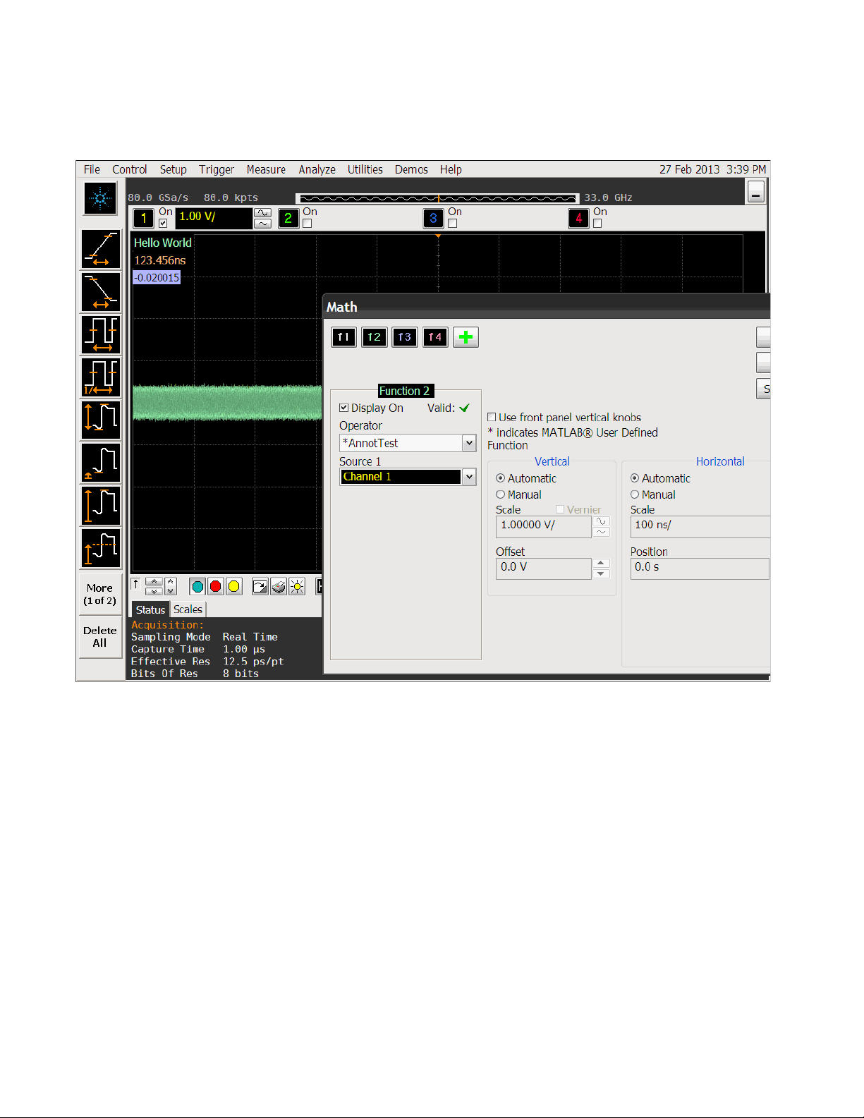
Result
MATLAB® Script File 3
Agilent N5430A User Defined Function User's and Programmer's Guide 29
Page 30

3 MATLAB® Script File
30 Agilent N5430A User Defined Function User's and Programmer's Guide
Page 31

Agilent N5430A User Defined Function
User's and Programmer's Guide
4
XML File
XML File Format 32
Tags for XML File 33
s1
31
Page 32

4 XML File
XML File Format
The XML file provides the framework for your mathematical
transformation MATLAB® script and describes to the User Defined
Function the necessary information to create the user interface. This file
must be placed in the proper directory:
• For the 8000 and 80000B Series oscilloscopes: C:\SCOPE\MATLAB
• For the 90000A or 9000A Series oscilloscopes with Windows XP: C:\
• For the 90000A or 9000A Series oscilloscopes with Windows 7: C:\
The maximum size of the file is 4096 characters.
The file contains tags and field values. The following is an example of the
file format.
Documents and Settings\All Users\Documents\Infiniium\User-Defined
Functions
Users\Public\Public Documents\Infiniium\User- Defined Functions
<?xml version="1.0" encoding="utf-8"?>
<Functions xmlns:xsi="http://www.w3.org/2001/XMLSchema-instance"
xsi:noNamespaceSchemaLocation="Functions.xsd" Version="1">
<Function>
<Name>Butterworth</Name>
<Abbreviation>BTR</Abbreviation>
</Functions>
<MATLABName>Butterworth</MATLABName>
<FunctionType>1 Source</FunctionType>
<FileIO>false</FileIO>
<SourceWindow>All</SourceWindow>
<XUnits>Same</XUnits>
<YUnits>Same</YUnits>
<Control Name = "Data Rate">
<Double>
<Min>1e9</Min>
<Max>10e9</Max>
<Resolution>1000</Resolution>
<Units>bitspersec</Units>
<Default>2.5e9</Default>
</Double>
</Control>
<Control Name = "Low Pass">
<Enumeration>
<Default>Off</Default>
<Selection>Off</Selection>
<Selection>On</Selection>
</Enumeration>
</Control>
</Function>
32 Agilent N5430A User Defined Function User's and Programmer's Guide
Page 33
XML File 4
Tags for XML File
All tags in the XML file have a starting and terminating tag. The
terminating tag has a forward slash. For example, the terminating tag for
the <Function> tag is the </Function>. The tags can be in any order except
where indicated otherwise. Also, the tags are case sensitive.
The following table shows a list of all of the tags and their descriptions.
Tag Description Required
Field?
<Functions Version = "1"> This is the root tag. All XML files must have one and only one
<Functions> tag. The <Functions> block can contain one or more
<Function> blocks. The Version attribute is optional but when used,
must be 1.
<Function> This tag defines a MATLAB® math function. One or more Function
tags can be used within a Functions tag. Up to 20 user-defined
functions are allowed. They can all be presented in a single file or in
individual files. All .xml files in c:\scope\MATLAB are parsed.
The following tags must be contained in the <Function> block.
<Name> This describes the name of the math operator that will appear in the
user interface. Infiniium will display from 1 to 16 character names.
Names with more than 16 characters in length will be truncated.
This is also the string that is passed to the GPIB
:FUNCtion<N>:MATLab:OPERator command to select this function.
<Abbreviation> This tag is the abbreviation for the operator that will appear in the
user interface. Infiniium will display as much of the abbreviation as it
can. From 1 to 6 characters are allowed.
<MATLABName> This tag lists the filename of the MATLAB® script without a suffix.
The MatLabName can be up to 24 characters.
<CheckAbort> This tag produces an abort dialog box after a specified number of
acquisition points have been passed to your MATLAB® script. This
provides a way for the user to cancel the function if it is taking to
long to finish. The following is an example where after 500,000
points are passed a dialog box is produced.
Ye s
Ye s
Ye s
Ye s
Ye s
No
<CheckAbort>500000</CheckAbort>
There also needs to be an entry in the MATLAB® script file in any
section that is likely to take a lot of time where a user may want to
cancel the function.
Agilent N5430A User Defined Function User's and Programmer's Guide 33
Page 34
4 XML File
Tag Description Required
Field?
<FunctionType> This tag determines the type of math function. This can be one of
the following values.
• 1 Source
• 2 Source
• Clock Data
• Sampled Clock Data
If this field is omitted, the value 1 Source is used. For 1 Source types,
your function should conform to the single source function interface.
For 2 Source types, your function should conform to the two source
function interface. For Clock Data types, your function should
conform to the clock data function interface.
<FileIO> When 'true', file based IO is used instead of memory based IO. File
based IO is useful when processing deep waveforms (greater than
8M points). See Chapter 6, “Deep User Defined Functions,” starting
on page 43.
<SourceWindow> This tag determines how much data is passed to your mathematical
transformation function. Valid values are All or Display. If All is
selected, all data in the source waveform record will be passed to
MATLAB®. If Display is selected, only the portion of the source
waveform that is on screen will be passed to MATLAB®. If this tag
is omitted, Display is assumed.
<XUnits> This tag allows you to select the units for the horizontal axis of your
function. If this field is omitted, same units are assumed. same units
uses the units that the source is using. The following is a list of valid
units.
same, Volt, second, meter, inch, Ohm, decibel or dB, Hertz, Ampere,
Watt, percent, ratio, unknown, constant, sample, point, division,
dBm, dBj, hour, waveform, hits, bit, gain, feet, Henry, Farad, minute,
degreeC, degreeF, UI, bitspersec, dBc, radian, degree
The units are not case sensitive.
<YUnits> This tag allows you to select the units for the vertical axis of your
function. If this field is omitted, same units are assumed. same units
uses the units that the source is using. The following is a list of valid
units.
same, Volt, second, meter, inch, Ohm, decibel or dB, Hertz, Ampere,
Watt, percent, ratio, unknown, constant, sample, point, division,
dBm, dBj, hour, waveform, hits, bit, gain, feet, Henry, Farad, minute,
degreeC, degreeF, UI, bitspersec, dBc, radian, degree
The units are not case sensitive.
<Source1Type>, <Source2Type> May be Digital, Bus, Channel, Function, Memory.
<Source1Title>, <Source2Title> String title of the label above the source control.
<Interpolate> false if SrcData should not be interpolated.
34 Agilent N5430A User Defined Function User's and Programmer's Guide
Page 35

XML File 4
Tag Description Required
Field?
<Variable> Pass a value from the XML file into the MATLAB script.
For example <Variable Name = "Bandwidth" Value = "20e9" /> will
pass a variable Bandwidth assigned the value 20 GHz to the
MATLAB script.
<Control Name="CtrlName"> This tag defines a control block. Zero, one, two, or three control
blocks are allowed for each function. The control block allows the
user interface entry associated with your function to be passed to
your MATLAB® function. This allows users to pass values from the
user interface to your MATLAB® function. The controls will be
presented in the scope user interface in the order presented here.
The following tags are all contained in the <Control> block. The
Name attribute is the name of the control that shows up in the user
interface. As much of the name as possible will be displayed. The
name can be up to 24 characters. There are four types of controls.
• Double — This control offers a range of floating point values.
• Integer — This control offers a range of integer values.
• Enumeration — This control offers the user to select from a list of
selections. Up to 10 selections can be offered.
• String — This control allows the user to input a string.
• File — This control is similar to the String control, but brings up a
file browse dialog in the user interface.
<Double>
<Min> This is the minimum inclusive double value that the user can enter. Yes
<Max> This is the maximum inclusive double value that the user can enter. Yes
<Resolution> This is the double resolution and increment for the up/down
stepper.
<Default> This is the default value for the control. The default value is applied
whenever the user selects your function operator. The default
should be between min and max.
<Units> This is the units associated with the control. The <XUnits> shows a
list of valid unit values except that the value same should not be
used.
<Integer>
<Min> This is the minimum inclusive integer value that the user can enter. Yes
<Max> This is the maximum inclusive integer value that the user can enter. Yes
<Resolution> This is the integer resolution and increment for the up/down
stepper. The default resolution is 1.
<Default> This is the default value for the control. The default value is applied
whenever the user selects your function operator. The default
should be between min and max.
Ye s
Ye s
Ye s
Ye s
Agilent N5430A User Defined Function User's and Programmer's Guide 35
Page 36
4 XML File
Tag Description Required
Field?
<Units> This is the units associated with the control. The <XUnits> shows a
list of valid unit values except that the value same should not be
used.
<Enumeration>
<Default> This is the default value for the control. The default value is applied
whenever the user selects your function operator. The default
should be the same value as one of the selections.
<Selection> This tag contains a selection string for an Enumeration type control.
Up to 10 selections are available. The selections will be presented in
the order listed here. The value that gets passed to your MATLAB®
script is the 1 based index of the selection. For example, if the user
selects the 5th selection, the value 5 will get passed to MATLAB®.
At lease one selection must be provided for an Enumeration type
control.
<String> The string control is particularly powerful as MATLAB® variables
can be entered and evaluated in MATLAB®. This allows a large
number of variable values to be passed into MATLAB®. The user
can enter a string of up to 128 characters.
<Default> This is the default string for the control.
<File> This control is similar to the String control, but brings up a file
browse dialog in the user interface.
Ye s
Ye s
Ye s
<Default> This is the default filename for the control.
36 Agilent N5430A User Defined Function User's and Programmer's Guide
Page 37

Agilent N5430A User Defined Function
User's and Programmer's Guide
5
GPIB Function Commands
:FUNCtion<N>:MATLab 38
:FUNCtion<N>:MATLab:CONTrol1 39
:FUNCtion<N>:MATLab:CONTrol2 40
:FUNCtion<N>:MATLab:CONTrol3 41
:FUNCtion<N>:MATLab:OPERator 42
The FUNCtion subsystem defines functions 1 to 4. These FUNCtion
commands and queries are implemented in the Infiniium oscilloscopes.
s1
37
Page 38

5 GPIB Function Commands
NOTE
:FUNCtion<N>:MATLab
Command :FUNCtion<N>:MATLab <operand>[,<operand>]
The :FUNCtion<N>:MATLab command sets the operand.
<N> An integer, 1 - 4, representing the selected function.
<operand> {CHANnel<N> | FUNCtion<N> | WMEMory<N>}
CHANnel<N> is an integer, 1 - 4.
FUNCtion<N> and WMEMory<N> are:
An integer, 1 - 4, representing the selected function or waveform memory.
Example This example sets the operand to channel 3.
10 OUTPUT 707;":FUNCtion1:MATLab CHANnel3"
20 END
Functions Used as Operands
A function may be used as a source for another function, subject to the following
constraints:
F4 can have F1, F2, or F3 as a source.
F3 can have F1 or F2 as a source.
F2 can have F1 as a source.
F1 cannot have any other function as a source.
38 Agilent N5430A User Defined Function User's and Programmer's Guide
Page 39

GPIB Function Commands 5
:FUNCtion<N>:MATLab:CONTrol1
Command :FUNCtion<N>:MATLab:CONTrol1 {<value> | <string>}
The :FUNCtion<N>:MATLab:CONTrol1 command sets control 1.
<N> An integer, 1 - 4, representing the selected function.
<value> a double, integer, or enumerated type value. For an enumerated type, the
1 based index is passed to select the enumeration.
<string> a character array.
Example This example sets control 1 to 3.
10 OUTPUT 707;"FUNCtion1:MATLab:CONTrol1 3"
20 END
Query :FUNCtion<N>:MATLab:CONTrol1?
The :FUNCtion<N>:MATLab:CONTrol1? query returns the value or string of
control 1.
Returned Format
Example This example places the current returned value for function 1 control 1 in
[:FUNCtion<N>:MATLab:CONTrol1]{<value> | <string>}<NL>
the string variable, Selection$, then prints the contents of the variable to
the computer's screen.
10 DIM Selection$[50]
20 OUTPUT 707;":FUNCtion1:MATLab:CONTrol1?"
30 ENTER 707;Selection$
40 PRINT Selection$
50 END
Agilent N5430A User Defined Function User's and Programmer's Guide 39
Page 40

5 GPIB Function Commands
:FUNCtion<N>:MATLab:CONTrol2
Command :FUNCtion<N>:MATLab:CONTrol2 {<value> | <string>}
The :FUNCtion<N>:MATLab:CONTrol2 command sets control 2.
<N> An integer, 1 - 4, representing the selected function.
<value> a double, integer, or enumerated type value. For an enumerated type, the
1 based index is passed to select the enumeration.
<string> a character array.
Example This example sets control 2 to 3.
10 OUTPUT 707;"FUNCtion1:MATLab:CONTrol2 3"
20 END
Query :FUNCtion<N>:MATLab:CONTrol2?
The :FUNCtion<N>:MATLab:CONTrol2? query returns the value or string of
control 2.
Returned Format
[:FUNCtion<N>:MATLab:CONTrol2]{<value> | <string>}<NL>
Example This example places the current returned value for function 1 control 2 in
the string variable, Selection$, then prints the contents of the variable to
the computer's screen.
10 DIM Selection$[50]
20 OUTPUT 707;":FUNCtion1:MATLab:CONTrol2?"
30 ENTER 707;Selection$
40 PRINT Selection$
50 END
40 Agilent N5430A User Defined Function User's and Programmer's Guide
Page 41

GPIB Function Commands 5
:FUNCtion<N>:MATLab:CONTrol3
Command :FUNCtion<N>:MATLab:CONTrol3 {<value> | <string>}
The :FUNCtion<N>:MATLab:CONTrol3 command sets control 3.
<N> An integer, 1 - 4, representing the selected function.
<value> a double, integer, or enumerated type value. For an enumerated type, the
1 based index is passed to select the enumeration.
<string> a character array.
Example This example sets control 3 to 3.
10 OUTPUT 707;"FUNCtion1:MATLab:CONTrol3 3"
20 END
Query :FUNCtion<N>:MATLab:CONTrol3?
The :FUNCtion<N>:MATLab:CONTrol3? query returns the value or string of
control 3.
Returned Format
Example This example places the current returned value for function 1 control 3 in
[:FUNCtion<N>:MATLab:CONTrol3]{<value> | <string>}<NL>
the string variable, Selection$, then prints the contents of the variable to
the computer's screen.
10 DIM Selection$[50]
20 OUTPUT 707;":FUNCtion1:MATLab:CONTrol3?"
30 ENTER 707;Selection$
40 PRINT Selection$
50 END
Agilent N5430A User Defined Function User's and Programmer's Guide 41
Page 42

5 GPIB Function Commands
:FUNCtion<N>:MATLab:OPERator
Command :FUNCtion<N>:MATLab:OPERator <string>
The :FUNCtion<N>:MATLab:OPERator command sets the Math dialog box
operator.
<N> An integer, 1 - 4, representing the selected function.
<string> a character array that is the name of the function in the XML file.
Example This example sets function 1 to the Deconvolve operator.
10 OUTPUT 707;":FUNCtion1:MATLab:OPERator 'Deconvolve'"
20 END
Query :FUNCtion<N>:MATLab:OPERator?
The :FUNCtion<N>:MATLab:OPERator? query returns the string of the
function 1 operator.
Returned Format
[:FUNCtion<N>:MATLab:OPERator]<string><NL>
Example This example places the current operator string for function 1 in the
string variable, Selection$, then prints the contents of the variable to the
computer's screen.
10 DIM Selection$[50]
20 OUTPUT 707;":FUNCtion1:MATLab:OPERator?"
30 ENTER 707;Selection$
40 PRINT Selection$
50 END
42 Agilent N5430A User Defined Function User's and Programmer's Guide
Page 43

Agilent N5430A User Defined Function
User's and Programmer's Guide
6
Deep User Defined Functions
For the 90000A, 90000 X-Series, or 9000A Series oscilloscopes, software
version 3.11 and later has the ability to perform file based IO for user
defined functions (UDF). This permits applying a function to a longer
memory depth than would otherwise be allowed. While there are no hard
constraints on the length of a waveform to pass in or out of a function,
you will likely run out of memory in the oscilloscope application when
trying to pass deep waveforms (greater than 8M points).
For deep waveforms, you can instead use a file to pass the data in and
out of a UDF. To use file based IO, the MATLAB script needs to read from
and write to a file.
In most cases, you will want to process a part of the source data at a time
so as to not create internal MATLAB arrays that are too large.
Also, the .XML file must contain a keyword to tell the oscilloscope to use
file IO. This line should be added to the .XML file that configures the
oscilloscope:
<FileIO>true</FileIO>
Instead of passing SrcData, Src1Data, or Src2Data variables to MATLAB,
the oscilloscope passes SrcDataFile, Src1DataFile, or Src2DataFile
variables. These variables are strings that are the filename and path to the
files that contain source data.
In the MATLAB script, create a variable 'FnDataFile' that is the path and
filename of the resultant data.
The source and function data files are binary files of type 'double'.
Here is an example script that creates the square root of the sum of
squares of the input waveforms:
% Open the source files with read access.
Src1Fid = fopen(Src1DataFile,'r');
Src2Fid = fopen(Src2DataFile,'r');
% Get the size of the files to determine the number of points.
File1Details = dir(Src1DataFile);
File2Details = dir(Src2DataFile);
% In this example, process the data in chunks of 100000 points.
PacketSize = 100000;
s1
43
Page 44

6 Deep User Defined Functions
% The files contain binary double data, or 8 bytes per point.
BytesPerDouble = 8;
% Find the smaller of the two sources.
Bytes = min(File1Details.bytes, File2Details.bytes);
% Compute how may chunks to process.
NumPackets = int32((Bytes / BytesPerDouble) / PacketSize);
% Round up. Could use ceil().
if NumPackets * PacketSize < (Bytes / BytesPerDouble)
NumPackets = NumPackets + 1;
end
% Get the path of the source data files.
[PathStr, Name] = fileparts(Src1DataFile);
% Using the same path, create a FnData file.
FnDataFile = [PathStr,'\FnData'];
% Open the output file with write access.
[FnFid, Message] = fopen(FnDataFile,'w');
% For each chunk of data:
for i = 1:NumPackets
% Read the source data from the file.
Src1Data = fread(Src1Fid,PacketSize,'double');
Src2Data = fread(Src2Fid,PacketSize,'double');
% Compute result.
FnData = sqrt((Src1Data .* Src1Data) + (Src2Data .* Src2Data));
% Write the result.
fwrite(FnFid, FnData, 'double');
end
% Scaling for this particular function.
Src1YScale = Src1YScale / 2.0 + Src1YMiddle;
Src2YScale = Src2YScale / 2.0 + Src2YMiddle;
FnYScale = sqrt(Src1YScale * Src1YScale + Src2YScale * Src2YScale);
FnYMiddle = FnYScale / 2.0;
% Don't forget to close all files.
fclose(Src1Fid);
fclose(Src2Fid);
fclose(FnFid);
44 Agilent N5430A User Defined Function User's and Programmer's Guide
Page 45

Index
Symbols
:FUNCtion<N>:MATLab command, 38
:FUNCtion<N>:MATLab:CONTrol1
command/query, 39
:FUNCtion<N>:MATLab:CONTrol2
command/query, 40
:FUNCtion<N>:MATLab:CONTrol3
command/query, 41
:FUNCtion<N>:MATLab:OPERator
command/query, 42
Numerics
1 Source operator variables, 18
2 Source operator, Variables, 19
A
Annotation variables, 23
Annotations, example, 28
C
Clock Data operator variables, 20
CONTrol1, :FUNCtion<N>:MATLab:CONTrol1
command/query, 39
CONTrol2, :FUNCtion<N>:MATLab:CONTrol2
command/query, 40
CONTrol3, :FUNCtion<N>:MATLab:CONTrol3
command/query, 41
D
deep User Defined Functions, 43
E
example, Annotations, 28
example, Deep User Defined Function, 43
I
in this book, 4
Infiniium Oscilloscope software, 9
installation, 7
installing User Defined Function, 15
L
license code, 11
M
MATLAB interface, 18
MATLAB script example, 26
MATLAB script file, 17
MATLAB software, 10
MATLab, :FUNCtion<N>:MATLab
command, 38
MATLab, :FUNCtion<N>:MATLab:CONTrol1
command/query, 39
MATLab, :FUNCtion<N>:MATLab:CONTrol2
command/query, 40
MATLab, :FUNCtion<N>:MATLab:CONTrol3
command/query, 41
MATLab, :FUNCtion<N>:MATLab:OPERator
command/query, 42
N
N5430A User Defined Function software, 3
notices, 2
O
OPERator, :FUNCtion<N>:MATLab:OPERator
command/query, 42
overview, 13
R
T
tags for XML file, 33
trademarks, 2
U
User Defined Function (N5430A), 3
User Defined Function (UDF), 14
V
variable definitions, 23
variables, 1 Source operator, 18
variables, 2 Source operator, 19
variables, Clock Data operator, 20
variables, Sampled Clock Data operator, 21
X
XML file, 31
XML file format, 32
F
file IO, 43
remote commands, 37
requirements, software, 8
S
G
GPIB function commands, 37
Agilent N5430A User Defined Function User's and Programmer's Guide 45
SCPI commands, 37
software requirements, 8
Page 46

Index
46 Agilent N5430A User Defined Function User's and Programmer's Guide
Loading...