

Page 1

User’s Guide
Agilent Technologies
N5181A/82A MXG Signal Generators
This guide applies to the followin g sign al ge nerator models:
N5181A MXG Analog Signal Generator
N5182A MXG Vector Signal Generator
Because of our continuing efforts to improve our products through firmware and hardware revisio ns, si gn al gene rato r des ign
and operation may vary from descriptions in this guide. We recommend that you use the latest revision of this guide to
ensure that you have up-to-date product information. Compare the print date of this guide (see bottom of page) with the
latest revision, which can be downloaded from the followin g website:
http://www.agilent.com/find/mxg
Manufacturing Part Number: N5180- 90003
Printed in USA
September 2006
© Copyright 2006 Agilent Technologies, Inc.
Page 2

Notice
The material contained in this document is provided “as is”, and is subject to being changed, without
notice, in future editions.
Further, to the maximum extent permitted by applicable law, Agilent disclaims all warranties, either
express or implied with regard to this manual and to any of the Agilent products to which it
pertains, including but not limited to the implied warranties of merchantability and fitness for a
particular purpose. Agilent shall not be liable for errors or for incidental or consequential damages in
connection with the furnishing, use, or performance of this document or any of the Agilent products
to which it pertains. Should Agilent have a written contract with the User and should any of the
contract terms conflict with these terms, the contract terms shall control.
ii Agilent N5181A/82A MXG Signal Generators User’sG uide
Page 3

Contents
1 Signal Generator Overview
Signal Generator Features . . . . . . . . . . . . . . . . . . . . . . . . . . . . . . . . . . . . . . . . . . . . . . .2
Front Panel Overview . . . . . . . . . . . . . . . . . . . . . . . . . . . . . . . . . . . . . . . . . . . . . . . . . .3
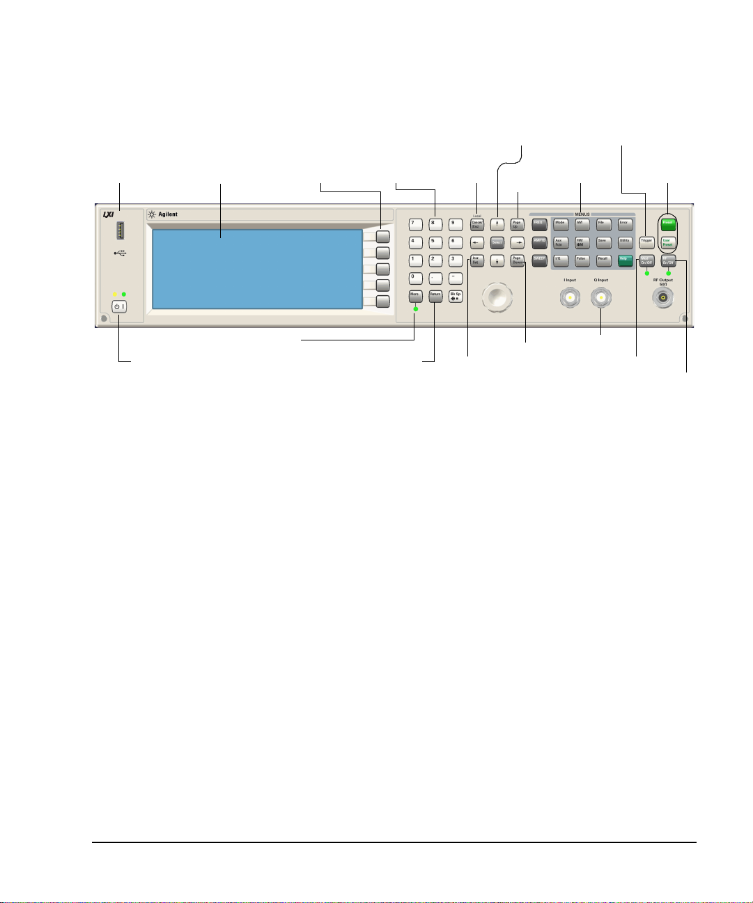
1. Host USB . . . . . . . . . . . . . . . . . . . . . . . . . . . . . . . . . . . . . . . . . . . . . . . . . . . . .3
2. Display . . . . . . . . . . . . . . . . . . . . . . . . . . . . . . . . . . . . . . . . . . . . . . . . . . . . . . .3
3. Softkeys . . . . . . . . . . . . . . . . . . . . . . . . . . . . . . . . . . . . . . . . . . . . . . . . . . . . . .3
4. Numeric Keypad . . . . . . . . . . . . . . . . . . . . . . . . . . . . . . . . . . . . . . . . . . . . . . . . .3
5. Arrows and Select. . . . . . . . . . . . . . . . . . . . . . . . . . . . . . . . . . . . . . . . . . . . . . . .3
6. Page Up . . . . . . . . . . . . . . . . . . . . . . . . . . . . . . . . . . . . . . . . . . . . . . . . . . . . . .4
7. MENUS . . . . . . . . . . . . . . . . . . . . . . . . . . . . . . . . . . . . . . . . . . . . . . . . . . . . . . .4
8. Trigger . . . . . . . . . . . . . . . . . . . . . . . . . . . . . . . . . . . . . . . . . . . . . . . . . . . . . . .4
9. Local Cancel/(Esc) . . . . . . . . . . . . . . . . . . . . . . . . . . . . . . . . . . . . . . . . . . . . . . .4
10. Help . . . . . . . . . . . . . . . . . . . . . . . . . . . . . . . . . . . . . . . . . . . . . . . . . . . . . . . .4
11. Preset and User Preset . . . . . . . . . . . . . . . . . . . . . . . . . . . . . . . . . . . . . . . . . . . .4
12. RF Output . . . . . . . . . . . . . . . . . . . . . . . . . . . . . . . . . . . . . . . . . . . . . . . . . . . .5
13. RF On/Off and LED . . . . . . . . . . . . . . . . . . . . . . . . . . . . . . . . . . . . . . . . . . . . . .5
14. Mod On/Off and LED . . . . . . . . . . . . . . . . . . . . . . . . . . . . . . . . . . . . . . . . . . . . .5
15. Page Down . . . . . . . . . . . . . . . . . . . . . . . . . . . . . . . . . . . . . . . . . . . . . . . . . . . .5
16. I Input (vector models only) . . . . . . . . . . . . . . . . . . . . . . . . . . . . . . . . . . . . . . . .5
17. Q Input (vector models only) . . . . . . . . . . . . . . . . . . . . . . . . . . . . . . . . . . . . . . . .5
18. Knob. . . . . . . . . . . . . . . . . . . . . . . . . . . . . . . . . . . . . . . . . . . . . . . . . . . . . . . .6
19. Incr Set . . . . . . . . . . . . . . . . . . . . . . . . . . . . . . . . . . . . . . . . . . . . . . . . . . . . .6
20. Return . . . . . . . . . . . . . . . . . . . . . . . . . . . . . . . . . . . . . . . . . . . . . . . . . . . . . .6
21. More and LED . . . . . . . . . . . . . . . . . . . . . . . . . . . . . . . . . . . . . . . . . . . . . . . . .6
22. Power Switch and LEDs . . . . . . . . . . . . . . . . . . . . . . . . . . . . . . . . . . . . . . . . . . .6
Front Panel Display . . . . . . . . . . . . . . . . . . . . . . . . . . . . . . . . . . . . . . . . . . . . . . . . . . .7
1. Active Function Area . . . . . . . . . . . . . . . . . . . . . . . . . . . . . . . . . . . . . . . . . . . . . .7
2. Frequency Area . . . . . . . . . . . . . . . . . . . . . . . . . . . . . . . . . . . . . . . . . . . . . . . . .7
3. Annunciators . . . . . . . . . . . . . . . . . . . . . . . . . . . . . . . . . . . . . . . . . . . . . . . . . . .7
4. Amplitude Area . . . . . . . . . . . . . . . . . . . . . . . . . . . . . . . . . . . . . . . . . . . . . . . . .8
5. Error Message Area . . . . . . . . . . . . . . . . . . . . . . . . . . . . . . . . . . . . . . . . . . . . . . .8
6. Text Area . . . . . . . . . . . . . . . . . . . . . . . . . . . . . . . . . . . . . . . . . . . . . . . . . . . . .8
7. Softkey Label Area . . . . . . . . . . . . . . . . . . . . . . . . . . . . . . . . . . . . . . . . . . . . . . .8
Rear Panel Overview. . . . . . . . . . . . . . . . . . . . . . . . . . . . . . . . . . . . . . . . . . . . . . . . . . .9
1. AC Power Receptacle . . . . . . . . . . . . . . . . . . . . . . . . . . . . . . . . . . . . . . . . . . . . . .9
2. SWEEP OUT . . . . . . . . . . . . . . . . . . . . . . . . . . . . . . . . . . . . . . . . . . . . . . . . . . .9
3. AM. . . . . . . . . . . . . . . . . . . . . . . . . . . . . . . . . . . . . . . . . . . . . . . . . . . . . . . . . .9
4. FM . . . . . . . . . . . . . . . . . . . . . . . . . . . . . . . . . . . . . . . . . . . . . . . . . . . . . . . . . 10
5. PULSE . . . . . . . . . . . . . . . . . . . . . . . . . . . . . . . . . . . . . . . . . . . . . . . . . . . . . . 10
6. TRIG IN . . . . . . . . . . . . . . . . . . . . . . . . . . . . . . . . . . . . . . . . . . . . . . . . . . . . . 10
7. TRIG OUT . . . . . . . . . . . . . . . . . . . . . . . . . . . . . . . . . . . . . . . . . . . . . . . . . . . . 10
Agilent N5181A/82A MXG Signal Generators User’sGuide iii
Page 4

Contents
8. REF IN. . . . . . . . . . . . . . . . . . . . . . . . . . . . . . . . . . . . . . . . . . . . . . . . . . . . . . 10
9. 10 MHz OUT . . . . . . . . . . . . . . . . . . . . . . . . . . . . . . . . . . . . . . . . . . . . . . . . . . 11
10. GPIB . . . . . . . . . . . . . . . . . . . . . . . . . . . . . . . . . . . . . . . . . . . . . . . . . . . . . . 11
11. LAN . . . . . . . . . . . . . . . . . . . . . . . . . . . . . . . . . . . . . . . . . . . . . . . . . . . . . . . 11
12. Device USB . . . . . . . . . . . . . . . . . . . . . . . . . . . . . . . . . . . . . . . . . . . . . . . . . . 11
Digital Modulation Connectors (vector models only) . . . . . . . . . . . . . . . . . . . . . . . . . . 12
I OUT, QOUT, OUT, OUT . . . . . . . . . . . . . . . . . . . . . . . . . . . . . . . . . . . . . . . . . . . 12
EXT CLOCK . . . . . . . . . . . . . . . . . . . . . . . . . . . . . . . . . . . . . . . . . . . . . . . . . . . . 12
EVENT 1 . . . . . . . . . . . . . . . . . . . . . . . . . . . . . . . . . . . . . . . . . . . . . . . . . . . . . . 12
PAT TRIG IN. . . . . . . . . . . . . . . . . . . . . . . . . . . . . . . . . . . . . . . . . . . . . . . . . . . . 13
DIGITAL BUS I/O . . . . . . . . . . . . . . . . . . . . . . . . . . . . . . . . . . . . . . . . . . . . . . . . 13
AUX I/O. . . . . . . . . . . . . . . . . . . . . . . . . . . . . . . . . . . . . . . . . . . . . . . . . . . . . . . 13
2 Setting Preferences & Enabling Options
User Preferences . . . . . . . . . . . . . . . . . . . . . . . . . . . . . . . . . . . . . . . . . . . . . . . . . . . . 16
Display Settings . . . . . . . . . . . . . . . . . . . . . . . . . . . . . . . . . . . . . . . . . . . . . . . . . . 16
Power On and Preset . . . . . . . . . . . . . . . . . . . . . . . . . . . . . . . . . . . . . . . . . . . . . . 17
Front Panel Knob Resolution . . . . . . . . . . . . . . . . . . . . . . . . . . . . . . . . . . . . . . . . . 17
Setting Time and Date . . . . . . . . . . . . . . . . . . . . . . . . . . . . . . . . . . . . . . . . . . . . . 18
Upgrading Firmware. . . . . . . . . . . . . . . . . . . . . . . . . . . . . . . . . . . . . . . . . . . . . . . . . . 18
Remote Operation Preferences . . . . . . . . . . . . . . . . . . . . . . . . . . . . . . . . . . . . . . . . . . . 19
Configuring the GPIB Interface . . . . . . . . . . . . . . . . . . . . . . . . . . . . . . . . . . . . . . . . 19
Configuring the LAN Interface . . . . . . . . . . . . . . . . . . . . . . . . . . . . . . . . . . . . . . . . 20
Enabling LAN Services: Browser, Sockets, and VXI- 11. . . . . . . . . . . . . . . . . . . . . . . . . 20
Enabling an Option . . . . . . . . . . . . . . . . . . . . . . . . . . . . . . . . . . . . . . . . . . . . . . . . . . 21
Viewing Options and Licenses . . . . . . . . . . . . . . . . . . . . . . . . . . . . . . . . . . . . . . . . 21
3 Basic Operation
Presetting the Signal Generator . . . . . . . . . . . . . . . . . . . . . . . . . . . . . . . . . . . . . . . . . . 23
Viewing Key Descriptions . . . . . . . . . . . . . . . . . . . . . . . . . . . . . . . . . . . . . . . . . . . . . . 23
Entering and Editing Numbers and Text . . . . . . . . . . . . . . . . . . . . . . . . . . . . . . . . . . . . 24
Entering Numbers and Moving the Cursor . . . . . . . . . . . . . . . . . . . . . . . . . . . . . . . . 24
Entering Alpha Characters . . . . . . . . . . . . . . . . . . . . . . . . . . . . . . . . . . . . . . . . . . . 24
Example: Using a Table Editor . . . . . . . . . . . . . . . . . . . . . . . . . . . . . . . . . . . . . . . . 25
Setting Frequency and Power (Amplitude) . . . . . . . . . . . . . . . . . . . . . . . . . . . . . . . . . . . 26
Example: Configuring a 700 MHz, −20 dBm Continuous Wave Output . . . . . . . . . . . . . . 26
Configuring a Swept Output . . . . . . . . . . . . . . . . . . . . . . . . . . . . . . . . . . . . . . . . . . . . 27
Step Sweep . . . . . . . . . . . . . . . . . . . . . . . . . . . . . . . . . . . . . . . . . . . . . . . . . . . . . 28
List Sweep . . . . . . . . . . . . . . . . . . . . . . . . . . . . . . . . . . . . . . . . . . . . . . . . . . . . . 29
Example: Using a Single Sweep . . . . . . . . . . . . . . . . . . . . . . . . . . . . . . . . . . . . . . . 32
iv Agilent N5181A/82A MXG Signal Generators User’sG uide
Page 5

Contents
Example: Manual Control of Sweep . . . . . . . . . . . . . . . . . . . . . . . . . . . . . . . . . . . . . 33
Routing Signals . . . . . . . . . . . . . . . . . . . . . . . . . . . . . . . . . . . . . . . . . . . . . . . . . . 33
Modulating the Carrier Signal . . . . . . . . . . . . . . . . . . . . . . . . . . . . . . . . . . . . . . . . . . . . 34
Example . . . . . . . . . . . . . . . . . . . . . . . . . . . . . . . . . . . . . . . . . . . . . . . . . . . . . . . 34
Viewing, Saving, and Recalling Data. . . . . . . . . . . . . . . . . . . . . . . . . . . . . . . . . . . . . . . . 35
Viewing a Stored File . . . . . . . . . . . . . . . . . . . . . . . . . . . . . . . . . . . . . . . . . . . . . . 36
Saving and Recalling Data . . . . . . . . . . . . . . . . . . . . . . . . . . . . . . . . . . . . . . . . . . . 37
Working with Instrument State Files . . . . . . . . . . . . . . . . . . . . . . . . . . . . . . . . . . . . 38
Selecting Internal or External Media . . . . . . . . . . . . . . . . . . . . . . . . . . . . . . . . . . . . 41
Reading Error Messages . . . . . . . . . . . . . . . . . . . . . . . . . . . . . . . . . . . . . . . . . . . . . . . 42
Error Message Format . . . . . . . . . . . . . . . . . . . . . . . . . . . . . . . . . . . . . . . . . . . . . . 42
4 Optimizing Performance
Using User Flatness Correction . . . . . . . . . . . . . . . . . . . . . . . . . . . . . . . . . . . . . . . . . . . 44
Basic Procedure . . . . . . . . . . . . . . . . . . . . . . . . . . . . . . . . . . . . . . . . . . . . . . . . . . 44
Example: A 500 MHz to 1 GHz Flatness Correction Array with 10 Correction Values . . . . 45
Recalling and Applying a User Flatness Correction Array . . . . . . . . . . . . . . . . . . . . . . 46
Using Unleveled Operating Modes . . . . . . . . . . . . . . . . . . . . . . . . . . . . . . . . . . . . . . . . . 47
ALC Off Mode . . . . . . . . . . . . . . . . . . . . . . . . . . . . . . . . . . . . . . . . . . . . . . . . . . . 47
Power Search Mode. . . . . . . . . . . . . . . . . . . . . . . . . . . . . . . . . . . . . . . . . . . . . . . . 48
Using an Output Offset, Reference, or Multiplier . . . . . . . . . . . . . . . . . . . . . . . . . . . . . . . 49
Setting an Output Offset . . . . . . . . . . . . . . . . . . . . . . . . . . . . . . . . . . . . . . . . . . . . 49
Setting an Output Reference . . . . . . . . . . . . . . . . . . . . . . . . . . . . . . . . . . . . . . . . . . 50
Setting a Frequency Multiplier . . . . . . . . . . . . . . . . . . . . . . . . . . . . . . . . . . . . . . . . 51
5 Using Analog Modulation (Option UNT Only)
The Basic Procedure . . . . . . . . . . . . . . . . . . . . . . . . . . . . . . . . . . . . . . . . . . . . . . . . . . 54
Using an External Modulation Source . . . . . . . . . . . . . . . . . . . . . . . . . . . . . . . . . . . . . . 55
Removing a DC Offset . . . . . . . . . . . . . . . . . . . . . . . . . . . . . . . . . . . . . . . . . . . . . . 55
6 Using Puls e Modulatio n ( Option UNU)
Pulse Characteristics. . . . . . . . . . . . . . . . . . . . . . . . . . . . . . . . . . . . . . . . . . . . . . . . . . 59
The Basic Procedure . . . . . . . . . . . . . . . . . . . . . . . . . . . . . . . . . . . . . . . . . . . . . . . . . . 61
Example . . . . . . . . . . . . . . . . . . . . . . . . . . . . . . . . . . . . . . . . . . . . . . . . . . . . . . . . . . 61
7 Basic Digital Operation—No BBG Optio n Installed
I/Q Modulation . . . . . . . . . . . . . . . . . . . . . . . . . . . . . . . . . . . . . . . . . . . . . . . . . . . . . 64
Configuring the Front Panel Inputs . . . . . . . . . . . . . . . . . . . . . . . . . . . . . . . . . . . . . 65
Agilent N5181A/82A MXG Signal Generators User’sGuide v
Page 6

Contents
8 Basic Digital Operation (Optio n 651 /652/654)
Waveform File Basics . . . . . . . . . . . . . . . . . . . . . . . . . . . . . . . . . . . . . . . . . . . . . . . . . 68
Signal Generator Memory . . . . . . . . . . . . . . . . . . . . . . . . . . . . . . . . . . . . . . . . . . . 68
Dual ARB Player . . . . . . . . . . . . . . . . . . . . . . . . . . . . . . . . . . . . . . . . . . . . . . . . . 68
Storing, Loading, and Playing a Waveform Segment . . . . . . . . . . . . . . . . . . . . . . . . . . . . . 70
Storing/Renaming a Waveform Segment to Non- Volatile Memory (Internal or External Media)
70
Loading a Waveform Segment into BBG Media (Volatile Memory) . . . . . . . . . . . . . . . . . 71
Playing a Waveform Segment . . . . . . . . . . . . . . . . . . . . . . . . . . . . . . . . . . . . . . . . . 71
Setting the Baseband Frequency Offset . . . . . . . . . . . . . . . . . . . . . . . . . . . . . . . . . . . . . 72
Waveform Sequences . . . . . . . . . . . . . . . . . . . . . . . . . . . . . . . . . . . . . . . . . . . . . . . . . 74
Creating a Sequence . . . . . . . . . . . . . . . . . . . . . . . . . . . . . . . . . . . . . . . . . . . . . . . 75
Viewing the Contents of a Sequence . . . . . . . . . . . . . . . . . . . . . . . . . . . . . . . . . . . . 76
Editing a Sequence. . . . . . . . . . . . . . . . . . . . . . . . . . . . . . . . . . . . . . . . . . . . . . . . 76
Playing a Sequence. . . . . . . . . . . . . . . . . . . . . . . . . . . . . . . . . . . . . . . . . . . . . . . . 77
Saving a Waveform’s Settings & Parameters . . . . . . . . . . . . . . . . . . . . . . . . . . . . . . . . . . 78
Viewing and Modifying Header Information . . . . . . . . . . . . . . . . . . . . . . . . . . . . . . . 79
Viewing & Editing a Header without Selecting the Waveform . . . . . . . . . . . . . . . . . . . . 81
Using Waveform Markers . . . . . . . . . . . . . . . . . . . . . . . . . . . . . . . . . . . . . . . . . . . . . . . 82
Waveform Marker Concepts . . . . . . . . . . . . . . . . . . . . . . . . . . . . . . . . . . . . . . . . . . 83
Accessing Marker Utilities . . . . . . . . . . . . . . . . . . . . . . . . . . . . . . . . . . . . . . . . . . . 87
Viewing Waveform Segment Markers . . . . . . . . . . . . . . . . . . . . . . . . . . . . . . . . . . . . 88
Clearing Marker Points from a Waveform Segment . . . . . . . . . . . . . . . . . . . . . . . . . . . 88
Setting Marker Points in a Waveform Segment. . . . . . . . . . . . . . . . . . . . . . . . . . . . . . 89
Viewing a Marker Pulse. . . . . . . . . . . . . . . . . . . . . . . . . . . . . . . . . . . . . . . . . . . . . 92
Using the RF Blanking Marker Function . . . . . . . . . . . . . . . . . . . . . . . . . . . . . . . . . . 93
Setting Marker Polarity . . . . . . . . . . . . . . . . . . . . . . . . . . . . . . . . . . . . . . . . . . . . . 94
Controlling Markers in a Waveform Sequence . . . . . . . . . . . . . . . . . . . . . . . . . . . . . . 95
Using the EVENT Output Signal as an Instrument Trigger . . . . . . . . . . . . . . . . . . . . . . 97
Triggering a Waveform . . . . . . . . . . . . . . . . . . . . . . . . . . . . . . . . . . . . . . . . . . . . . . . . 98
Trigger Type . . . . . . . . . . . . . . . . . . . . . . . . . . . . . . . . . . . . . . . . . . . . . . . . . . . . 99
Trigger Source . . . . . . . . . . . . . . . . . . . . . . . . . . . . . . . . . . . . . . . . . . . . . . . . . . 100
Example: Segment Advance Triggering . . . . . . . . . . . . . . . . . . . . . . . . . . . . . . . . . . 101
Example: Gated Triggering . . . . . . . . . . . . . . . . . . . . . . . . . . . . . . . . . . . . . . . . . . 102
Example: External Triggering . . . . . . . . . . . . . . . . . . . . . . . . . . . . . . . . . . . . . . . . 104
Clipping a Waveform . . . . . . . . . . . . . . . . . . . . . . . . . . . . . . . . . . . . . . . . . . . . . . . . 105
How Power Peaks Develop . . . . . . . . . . . . . . . . . . . . . . . . . . . . . . . . . . . . . . . . . . 106
How Peaks Cause Spectral Regrowth . . . . . . . . . . . . . . . . . . . . . . . . . . . . . . . . . . . 108
How Clipping Reduces Peak-to- Average Power. . . . . . . . . . . . . . . . . . . . . . . . . . . . . 109
Configuring Circular Clipping . . . . . . . . . . . . . . . . . . . . . . . . . . . . . . . . . . . . . . . . 112
Configuring Rectangular Clipping . . . . . . . . . . . . . . . . . . . . . . . . . . . . . . . . . . . . . 113
vi Agilent N5181A/82A MXG Signal Generators User’sGuide
Page 7

Contents
Scaling a Waveform . . . . . . . . . . . . . . . . . . . . . . . . . . . . . . . . . . . . . . . . . . . . . . . . . 114
How DAC Over-Range Errors Occur . . . . . . . . . . . . . . . . . . . . . . . . . . . . . . . . . . . . 116
How Scaling Eliminates DAC Over- Range Errors. . . . . . . . . . . . . . . . . . . . . . . . . . . . 117
Setting Waveform Runtime Scaling . . . . . . . . . . . . . . . . . . . . . . . . . . . . . . . . . . . . . 118
Setting Waveform Scaling . . . . . . . . . . . . . . . . . . . . . . . . . . . . . . . . . . . . . . . . . . . 119
I/Q Modulation . . . . . . . . . . . . . . . . . . . . . . . . . . . . . . . . . . . . . . . . . . . . . . . . . . . . 121
Using the Rear Panel I and Q Outputs . . . . . . . . . . . . . . . . . . . . . . . . . . . . . . . . . . 122
Configuring the Front Panel Inputs . . . . . . . . . . . . . . . . . . . . . . . . . . . . . . . . . . . . 124
I/Q Adjustments. . . . . . . . . . . . . . . . . . . . . . . . . . . . . . . . . . . . . . . . . . . . . . . . . . . . 125
I/Q Calibration . . . . . . . . . . . . . . . . . . . . . . . . . . . . . . . . . . . . . . . . . . . . . . . . . . . . 127
9 Adding Real Time Noise to a Signal (Option 403)
Adding Real- Time Noise to a Dual ARB Waveform . . . . . . . . . . . . . . . . . . . . . . . . . . . . . 130
Using Real Time I/Q Baseband AWGN . . . . . . . . . . . . . . . . . . . . . . . . . . . . . . . . . . . . . 132
10 Working in a Secure Environment
Understanding Memory Types. . . . . . . . . . . . . . . . . . . . . . . . . . . . . . . . . . . . . . . . . . . 134
Removing Data from Memory (Option 006 Only) . . . . . . . . . . . . . . . . . . . . . . . . . . . . . . 136
Erase All . . . . . . . . . . . . . . . . . . . . . . . . . . . . . . . . . . . . . . . . . . . . . . . . . . . . . 136
Erase and Overwrite All . . . . . . . . . . . . . . . . . . . . . . . . . . . . . . . . . . . . . . . . . . . 137
Erase and Sanitize All. . . . . . . . . . . . . . . . . . . . . . . . . . . . . . . . . . . . . . . . . . . . . 137
Secure Mode . . . . . . . . . . . . . . . . . . . . . . . . . . . . . . . . . . . . . . . . . . . . . . . . . . . 137
Securing a Nonfunctioning Instrument . . . . . . . . . . . . . . . . . . . . . . . . . . . . . . . . . . 138
Using the Secure Display (Option 006 Only) . . . . . . . . . . . . . . . . . . . . . . . . . . . . . . . . . 139
11 Troubleshooting
Display. . . . . . . . . . . . . . . . . . . . . . . . . . . . . . . . . . . . . . . . . . . . . . . . . . . . . . . . . . 142
The Display is Too Dark to Read. . . . . . . . . . . . . . . . . . . . . . . . . . . . . . . . . . . . . . 142
Signal Generator Lock- Up . . . . . . . . . . . . . . . . . . . . . . . . . . . . . . . . . . . . . . . . . . . . . 142
RF Output . . . . . . . . . . . . . . . . . . . . . . . . . . . . . . . . . . . . . . . . . . . . . . . . . . . . . . . 143
No RF Output . . . . . . . . . . . . . . . . . . . . . . . . . . . . . . . . . . . . . . . . . . . . . . . . . . 143
Power Supply Shuts Down . . . . . . . . . . . . . . . . . . . . . . . . . . . . . . . . . . . . . . . . . . 143
No Modulation at the RF Output . . . . . . . . . . . . . . . . . . . . . . . . . . . . . . . . . . . . . . 143
RF Output Power too Low . . . . . . . . . . . . . . . . . . . . . . . . . . . . . . . . . . . . . . . . . . 143
Distortion . . . . . . . . . . . . . . . . . . . . . . . . . . . . . . . . . . . . . . . . . . . . . . . . . . . . . 143
Signal Loss While Working with a Spectrum Analyzer . . . . . . . . . . . . . . . . . . . . . . . . 144
Signal Loss While Working with a Mixer. . . . . . . . . . . . . . . . . . . . . . . . . . . . . . . . . 144
Agilent N5181A/82A MXG Signal Generators User’sGuide vii
Page 8

Contents
Sweep . . . . . . . . . . . . . . . . . . . . . . . . . . . . . . . . . . . . . . . . . . . . . . . . . . . . . . . . . . 146
Cannot Turn Off Sweep . . . . . . . . . . . . . . . . . . . . . . . . . . . . . . . . . . . . . . . . . . . 146
Sweep Appears Stalled . . . . . . . . . . . . . . . . . . . . . . . . . . . . . . . . . . . . . . . . . . . . 146
Incorrect List Sweep Dwell Time . . . . . . . . . . . . . . . . . . . . . . . . . . . . . . . . . . . . . 146
List Sweep Information is Missing from a Recalled Register . . . . . . . . . . . . . . . . . . . . 146
Amplitude Does Not Change in List or Step Sweep . . . . . . . . . . . . . . . . . . . . . . . . . 146
Internal Media Data Storage . . . . . . . . . . . . . . . . . . . . . . . . . . . . . . . . . . . . . . . . . . . 147
Instrument State Saved but the Register is Empty or Contains the Wrong State . . . . . . 147
External Media Data Storage . . . . . . . . . . . . . . . . . . . . . . . . . . . . . . . . . . . . . . . . . . . 147
Instrument Recognizes External Media Connection, but Does Not Display Files . . . . . . . 147
Preset . . . . . . . . . . . . . . . . . . . . . . . . . . . . . . . . . . . . . . . . . . . . . . . . . . . . . . . . . . 147
The Signal Generator Does Not Respond . . . . . . . . . . . . . . . . . . . . . . . . . . . . . . . . 147
Pressing Preset Performs a User Preset . . . . . . . . . . . . . . . . . . . . . . . . . . . . . . . . . 147
Error Messages . . . . . . . . . . . . . . . . . . . . . . . . . . . . . . . . . . . . . . . . . . . . . . . . . . . . 148
Error Message Types . . . . . . . . . . . . . . . . . . . . . . . . . . . . . . . . . . . . . . . . . . . . . 148
Error Message File . . . . . . . . . . . . . . . . . . . . . . . . . . . . . . . . . . . . . . . . . . . . . . . 148
Front Panel Tests . . . . . . . . . . . . . . . . . . . . . . . . . . . . . . . . . . . . . . . . . . . . . . . . . . 149
Self Test . . . . . . . . . . . . . . . . . . . . . . . . . . . . . . . . . . . . . . . . . . . . . . . . . . . . . . . . 149
Licenses. . . . . . . . . . . . . . . . . . . . . . . . . . . . . . . . . . . . . . . . . . . . . . . . . . . . . . . . . 150
A Time- Based License Quits Working . . . . . . . . . . . . . . . . . . . . . . . . . . . . . . . . . . 150
Cannot Load a Time- Based License. . . . . . . . . . . . . . . . . . . . . . . . . . . . . . . . . . . . 150
Contacting Agilent Technologies . . . . . . . . . . . . . . . . . . . . . . . . . . . . . . . . . . . . . . . . . 151
Returning a Signal Generator to Agilent . . . . . . . . . . . . . . . . . . . . . . . . . . . . . . . . . 151
viii Agilent N5181A/82A MXG Signal Generators User’sG uide
Page 9

Documentation Overview
Installation Guide
User’s Guide
Programming Guide
SCPI Reference
• Safety Information
• Receiving the Instr ument
• Environmental & Electrical Requirements
• Basic Setup
• Accessories
• Operation Verification
• Regulatory Information
• Instrument Overview
• Front Panel Operation
• Security
• Basic Troubleshooting
• Remote Operation
• Status Registers
• Creating & Downloading Files
• SCPI Basics
• Command Descriptions
• Programming Command Compatibility
Service Guide
• Troubleshooting
• Assembly Replacement
• Replaceable Parts
• Post- Repair Procedures
• Safety and Regula tor y Information
Key H el p
a
• Key function description
• Related SCPI commands
a
Press the Help hardkey, and then the key for which you wish help.
Agilent N5181A/82AMXG Signal Generators User’sGuide ix
Page 10

x Agilent N5181A/82A MXG Signal Generators User’sGuide
Page 11

1 Signal Generator Overview
• Signal Generator Features on page 2
• Front Panel Overview on page 3
• Front Panel Display on page 7
• Rear Panel Overview on page 9
Agilent N5181A/82AMXG Signal Generators User’sGuide 1
Page 12

Signal Generator Overview
Signal Generator Features
Signal Generator Features
• N5181A, analog models: 250 kHz to 1, 3, or 6 GHz
N5182A, vector models: 250 kHz to 3 or 6 GHz
• electronic attenuator
• step & list sweep of frequency, power, or frequency and power
vector models can include waveforms in list sweep
• user flatness correction
• automatic leveling control (ALC); power calibration
• 10 MHz reference oscillator with external output
• flexible reference input, 1 – 50 MHz (Option 1ER)
• GPIB, USB 2.0, and 100Base- T LAN interfaces
• analog modulation: AM, FM, and ΦM (Option UNT)
• external AM, FM, and ΦM inputs (Option UNT)
• pulse modulation (Option UNU)
• SCPI and IVI- COM driver
• 8648/ESG code compatible
• LXI Class C compliant
• external analog I/Q inputs (vector models)
• analog differential I/Q outputs (vector models, Option 1EL)
• arbitrary I/Q waveform playback up to 125 MSa/s (vector models, Option 654)
• with Signal Studio Software, vector models can generate 802.11 WLAN, W- CDMA, cdma2000,
1xEV- DO, GSM, EDGE, and more
For more details on hardware, firmware, software, and documentation features and options, refer to
the data sheet shipped with the signal generator and available from the Agilent Technologies website.
1. Open: http://www.agilent.com/find/mxg
2. Select the desired model number.
3. In the options and price list section, click price list.
2 A gilent N5181A/ 82A MXG SignalGeneratorsUser’s Guide
Page 13
Front Panel Overview
D
8. Tri gger
1. Host USB
2. Display
MXG Vector Signal Generator
N5181A 250 kHz - 6 GHz
3. Softkeys
4. Numeric
Keypad
5. Arrows and Select
9. Local
Cancel/(Esc)
6. Page Up
Signal Generator Overview
Front Panel Overvi ew
7. MENUS
and
10. Help
11. Preset
and User
Preset
12. RF
Output
21. More and LED
22. Power Switch and LEDs
20. Return
18. Knob
19. Incr Set
16. I Input
15. Page Down
17. Q Input
14. Mod On/Off and LED
13. RF On/Off and LE
1. Host USB
Connector Type A
USB Protocol 2.0
Use this universal serial bus (USB) to connect a memory stick for data transfer. You can connect or
disconnect a USB device without shutting down or restarting the signal generator. The instrument
also has a rear- panel device USB connector (see page 11) used to remotely control the instrument.
2. Display
The LCD screen provides information on the current function. Information can include status
indicators, frequency and amplitude settings, and error messages. Labels for the softkeys are located
on the right- hand side of the display. See also, “Front Panel Display” on page 7.
3. Softkeys
A softkey activates the function indicated by the displayed label to the left of the key.
4. Numeric Keypad
The numeric keypad comprises the 0 through 9 hardkeys, a decimal point hardkey, a minus sign
hardkey, and a backspace hardkey. See “Entering and Editing Numbers and Text” on page 24.
5. Arrows and Select
The Select and arrow hardkeys enable you to select items on the signal generator’s display for editing.
See “Entering and Editing Numbers and Text” on page 24.
Agilent N5181A/82AMXG Signal Generators User’sGuide 3
Page 14

Signal Generator Overview
Front Panel Overview
6. Page Up
In a table editor, use this hardkey to display a previous page. See “Example: Using a Table Editor” on
page 25. When text does not fit on one page in the display area, use this key in conjunction with the
Page Down key (page 5) to scroll text.
7. MENUS
These hardkeys open softkey menus that enable you to configure instrument functions or access
information.
See page 67
Reserved for
future use.
See page 26
See page 26
See page 27
Active only on
vector models.
See page 53
See page 57
See page 35
See page 42
See page 15
See page 23
See page 38
8. Trigger
When trigger mode is set to Trigger Key, this hardkey initiates an immediate trigger event for a
function such as a list or step sweep.
9. Local Cancel/(Es c)
This hardkey deactivates remote operation and returns the signal generator to front panel control,
cancels an active function entry, and cancels long operations (such an IQ calibration).
10. Help
Use this key to display a description of any hardkey or softkey. See “Viewing Key Descriptions” on
page 23.
11. Preset and User Preset
These hardkeys set the signal generator to a known state (factory or user- defined). See “Presetting
the Signal Generator” on page 23.
4 A gilent N5181A/ 82A MXG SignalGeneratorsUser’s Guide
Page 15

12. RF Output
Signal Generator Overview
Front Panel Overvi ew
Connector Standard:
Option 1EM:
Impedance:
Damage Levels 50Vdc, 2W maximum RF power
female Type- N
Rear panel female Type- N
50Ω
13. RF On/Off and LE D
This hardkey toggles the operating state of the RF signal present at the RF OUTPUT connector. The
RF On/Off LED lights when RF output is enabled.
14. Mod On/Off and LED
This hardkey enables or disables the modulation of the output carrier signal by an active modulation
format. This hardkey does not set up or activate a format (see “Modulating the Carrier Signal” on
page 34).
The MOD ON/OFF LED lights when modulation of the output is enabled.
15. Page Down
In a table editor, use this hardkey to display the next page. See “Example: Using a Table Editor” on
page 25. When text does not fit on one page in the display area, use this key in conjunction with the
Page Up key (page 4) to scroll text.
16. I Input (vector models only)
Connector Type: female BNC Impedance: 50Ω
Signal An externally supplied analog, in- phase component of I/Q modulation.
The signal level is = 0.5 V
Damage Levels 1V
rms
for a calibrated output level.
rms
See also, “I/Q Modulation” on page 121.
17. Q Input (vector models only)
Connector Type: female BNC Impedance: 50Ω
Signal An externally supplied analog, quadrature- phase component of I/Q modulation.
The signal level is = 0.5 V
Damage Levels 1V
See also, “I/Q Modulation” on page 121.
Agilent N5181A/82AMXG Signal Generators User’sGuide 5
rms
for a calibrated output level.
rms
Page 16

Signal Generator Overview
Front Panel Overview
18. Knob
Rotating the knob increases or decreases a numeric value, or moves the highlight to the next digit,
character, or item in a list. See also, “Front Panel Knob Resolution” on page 17.
19. Incr Set
This hardkey enables you to set the increment value of the currently active function. The increment
value also affects how much each turn of the knob changes an active function’s value, according to
the knob’s current ratio setting (see “Front Panel Knob Resolution” on page 17).
20. Return
This hardkey enables you to retrace key presses. In a menu with more than one level, the Return key
returns to the prior menu page.
21. More and LED
When a menu contains more softkey labels than can be displayed, the More LED lights and a More
message displays below the labels. To display the next group of labels, press the More hardkey.
22. Power Switch and LEDs
This switch selects the standby mode or the power on mode. In the standby position, the yellow LED
lights and all signal generator functions deactivate. The signal generator remains connected to the
line power, and some power is consumed by some internal circuits. In the on position, the green LED
lights and the signal generator functions activate.
6 A gilent N5181A/ 82A MXG SignalGeneratorsUser’s Guide
Page 17

Front Panel Display
.
Signal Generator Overview
Front Panel Display
1. Active Function Area
5. Error Message Area
2. Frequency Area
3. Annunciators
6. T ext Area
7. Softkey Label Area
4. Amplitude Area
Scroll Bar
If there is more
text than can be
displayed on one
screen, a scroll
bar appears here
Use the Page Up
and Page Down
keys to scroll
through the text.
1. Active Function Area
This area displays the currently active function. For example, if frequency is the active function, the
current frequency setting appears. If the currently active function has an increment value associated
with it, that value also appears.
2. Frequency Area
This area displays the current frequency setting.
3. Annunciators
Annunciators show the status of some of the signal generator functions, and indicate error
conditions. An annunciator position may be used by more than one annunciator; in this case, only
one of the functions sharing a given position can be active at a given time.
This annunciator appears when . . .
ΦM Phase modula tion is on. If you tur n frequency modulation on, the FM annunciator replaces ΦM.
ARB The ARB generator is on.
ALC OFF The ALC circuit is disabled. The UNLEVEL annunciator appears in the same position if the ALC is enabled and
AM Amplitude modulation is on.
ARMED A sweep has been initiated and the signal generator is waiting for the sweep trigger event.
ATTNHOLD The attenuator hold function is on. When this function is on, the attenuator is held at its current setting.
DETHTR The ALC detector heater is not up to temperature. To meet ALC specifications the heater must be at
AWGN Real Time I/Q Baseband additive white Gaussian noise is on.
Agilent N5181A/82AMXG Signal Generators User’sGuide 7
is unable to maintain the output level.
temperature.
Page 18

Signal Generator Overview
Front Panel Display
This annunciator appears when . . .
DIGBUS The digital bus is in use.
ERR An error message is placed in the error queue. This annunciator does not turn off until you either view all of
EXTREF An external frequency reference is applied.
FM Frequency modulation is on. If you turn phase modulation on, the ΦM annunciator replaces FM.
I/Q I/Q vector modulation is on.
L The signal generator is in listener mode and is receiving information or commands over the GPIB, USB, or
MULT A frequency multiplier is set (see “Setting a Frequency Multiplier” on page 51).
OFFS An output offset is set (see “Setting an Output Offset” on page 49).
PULSE Pulse modulation is on.
R The signal generator is remotely controlled over the GPIB, USB, or VXI- 11/Sockets (LAN) interface.
REF An output reference is set (see “Setting an Output Reference” on page 50).
S The signal generator has generated a service request (SRQ) over the GPIB, USB, or VXI- 11/Sockets (LAN)
SWEEP The signal generator is currently sweeping in list or step mode.
SWMAN The signal generator is in manual sweep mode.
T The signal generator is in talker mode and is transmitting information over the GPIB, USB, or VXI- 11/Sockets
UNLEVEL The signal generator is unable to maint ain the correct output level. This is not necessarily an indication of
UNLOCK Any of the phase locked loops cannot maintain phase lock. To determine which loop is unlocked, examine the
WINIT The signal generator is waiting for you to initiate a single sweep.
the error messages or clear the error queue (see “Reading Error Messages” on page 42).
VXI- 11/Sockets (LAN) interface.
interface.
(LAN) interface.
instrument failure; unleveled conditions can occur during normal operation. Another annunciator, ALC OFF,
appears in the same position when the ALC circuit is disabled (see ALC OFF, above).
error messages (see “Reading Error Messages” on page 42).
4. Amplitude Area
This area displays the current output power level setting.
5. Error Message Area
This area displays abbreviated error messages. If multiple messages occur, only the most recent
message remains displayed. See “Reading Error Messages” on page 42.
6. Text Area
This area displays signal generator status information, such as the modulation status, and other
information such as sweep lists and file catalogs. This area also enables you to perform functions
such as managing information (entering information, and displaying or deleting files).
7. Softkey Label Area
This area displays labels that define the function of the softkeys located immediately to the right of
the display. Softkey labels change, depending on the function selected.
8 A gilent N5181A/ 82A MXG SignalGeneratorsUser’s Guide
Page 19

Rear Panel Overview
Signal Generator Overview
Rear Panel Overvi ew
Digital Modulation Connectors (vector models only) on page 12
Option 1EM
only
See page 5
3. AM
2. SWEEP OUT
4. FM
6. TRIG IN
5. PULSE
7. TRIG OUT
9. 10 MHz OUT
8. REF IN
1. AC Power Receptacle
10. GPIB
11. LAN
12. Device USB
1. AC Power Receptacle
The AC power cord receptacle accepts a three- pronged AC power cord that is supplied with the
signal generator. For details on line setting requirements and the power cord, see the
Installation Guide.
2. SWEEP OUT
Connector female BNC
Can drive 2 kΩ.
Signal Voltage range: 0 to +10V, regardless of sweep width
In swept mode: beginning of sweep = 0V; end of sweep = +10V
In CW mode: no output
This is a multiple use connector. For signal routing selections, see pages 33 and 57.
Impedance <1Ω
3. AM
Connector female BNC Impedance nominally 50Ω
Signal An externally supplied ±1V
Damage Levels 5V
Agilent N5181A/82AMXG Signal Generators User’sGuide 9
and 10V
rms
p
signal that produces the indicated depth.
p
Page 20

Signal Generator Overview
Rear Panel Overvi ew
4. FM
Connector female BNC Impedance nominally 50Ω
Signal An externally supplied ±1V
Damage Levels 5V
and 10V
rms
p
signal that produces the indicated deviation
p
5. PULSE
Connector female BNC Impedance nominally 50Ω
Signal Externally supplied: +1V = on; 0V = off
Damage Levels 5V
and 10V
rms
p
6. TRIG IN
Connector female BNC Impedance high Z
Signal An externally supplied TTL or CMOS signal for triggering operations, such as
point-to-point in manual sweep mode or an LF sweep in external sweep mode.
Triggering can occur on either the positive or negative edge.
Damage Levels ≤ −0.5V and ≥ +5.5V
7. TRIG OUT
Connector female BNC Impedance nominally 50Ω
Signal A TTL signal that is high at the start of a dwell sequence, or when waiting for the point
trigger in manual sweep mode.
It is low when the dwell is over, or when the point trigger is received.
The logic polarity can be reversed.
This is a multiple use connector. For signal routing selections, see pages 33 and 57.
8. REF IN
Connector female BNC Impedance nominally 50Ω
Signal An externally supplied −3.5 to +20 dBm signal from a timebase reference that is
within ±1 ppm.
In its factory default mode, the signal generator can detect a valid reference signal at this connector
and automatically switch from internal to external reference operation. See “Presetting the Signal
Generator” on page 23. With Option 1ER (flexible reference input), you must explicitly tell the signal
generator the external reference frequency you wish to use; enter the information through the front
panel or over the remote interface.
10 Agilent N5181A/82A MXG Signal Generators User’s Guide
Page 21

Signal Generator Overview
Rear Panel Overvi ew
9. 10 MHz OUT
Connector female BNC Impedance nominally 50Ω
Signal A nominal signal level greater than 4 dBm.
10. GPIB
This connector enables communication with compatible devices such as external controllers, and is
one of three connectors available to remotely control the signal generator (see also 11. LAN and
12. Device USB).
11. LAN
The signal generator supports local area network (LAN) based communication through this connector,
which enables a LAN- connected computer to remotely program the signal generator. The LAN
interface is LXI class C compliant; it does not support auto−MDIX. The signal generator is limited to
100 meters on a single cable (100Base-T). For more information on the LAN, refer to the
Programming Guide.
12. Device USB
Connector Mini- B
USB Protocol Version 2.0
Use this universal serial bus (USB) connector to connect a PC to remotely control the signal
generator.
Agilent N5181A/82AMXGSignal Generators User’sGuide 11
Page 22

Signal Generator Overview
I
Q
I
Q
Rear Panel Overvi ew
Digital Modulation Connectors (vector models only)
I OUT, QOUT, OUT, OUT
Connector Type: female BNC Impedance: 50Ω
DC- coupled
Signal
I OUT The analog, in-phase component of I/Q modulation from the internal baseband generator.
Q OUT The analog, quadrature-phase component of I/Q modulation from the internal baseband
OUT
OUT
Damage Levels > 1 Vrms DC Origin Offset typically <10 mV
Output Signal Levels into a 50Ω Load
a
Balanced signals are signals present in two separate conductors that are symmetrical relative to ground, and are opposite in polarity
(180degrees out of phase).
generator.
Used in conjunction with the I OUT connector to provide a balanced
Used in conjunction with the Q OUT connector to provide a balanced
• 0.5V
• 0.69V
• 0.71V
• Typically 1V
, typical, corresponds to one unit length of the I/Q vector
pk
(2.84 dB), typical, maximum crest factor for peaks for π/4 DQPSK, alpha = 0.5
pk
(3.08 dB), typical, maximum crest factor for peaks for π/4 DQPSK, alpha = 0.35
pk
maximum
p- p
a
baseband stimulus.
a
baseband stimulus.
EXT CLOCK
Connector female BNC Impedance nominally 50Ω
Signal An externally supplied TTL or CMOS bit clock signal where the rising edge aligns with the
beginning data bit.
The falling edge is used to clock external signals.
This signal is used with digital modulation applications.
Damage Levels > +8 and < −4V Maximum Clock Rate 50 MHz
EVENT 1
Connector female BNC Impedance: nominally 50Ω
Signal A pulse that can be used to trigger the start of a data pattern, frame, or timeslot.
Adjustable to ± one timeslot; resolution = one bit
Markers
Each Arb- based waveform point has a marker on/off condition associated with it.
Marker 1 level = +3.3V CMOS high (positive polarity selected); –3.3V CMOS low (negative
polarity selected).
Output on this connector occurs whenever Marker 1 is on in an Arb- based waveform (see
“Using Waveform Markers” on page 82).
Damage Levels >+8 and <−4V
12 Agilent N5181A/82A MXG Signal Generators User’s Guide
Page 23

Signal Generator Overview
t
E
A
A
M
E
M
O
p
P
A
T
r
T
c
T
S
T
D
Rear Panel Overvi ew
PAT TRIG IN
Connector female BNC Impedance: nominally 50Ω
Signal A TTL/CMOS low to TTL/CMOS high, or TTL/CMOS high to TTL/CMOS low edge trigger.
The input to this connector triggers the internal digital modulation pattern generator to start a
single pattern output or to stop and re-synchronize a pattern that is being continuously output.
To synchronize the trigger with the data bit clock, the trigger edge is latched, then sampled
during the falling edge of the internal data bit clock.
This is the external trigger for all ARB waveform generator triggers.
Minimum Trigger Input Pulse Width (high or low) = 100 ns
Minimum Trigger Delay (trigger edge to first bit of frame) = 1.5 to 2.5 bit clock periods
Damage Levels > +8 and < −4V
DIGITAL BUS I/O
This is a proprietary bus used by Agilent Technologies signal creation software. This connector is not
operational for general purpose use. Signals are present only when a signal creation software option
is installed (for details, refer to http://www.agilent.com/find/signalcreation).
AUX I/O
Pin 1 = Event 1
Pin 2 = Event 2
Pin 3 = Event 3
25
1
View looking into rear panel female 50-pin connector
2650
vent 1, 2, 3, and 4 (pins 1 − 4)
pulse that can be used to trigger the start of a data pattern, frame, or timeslot.
djustable to ± one timeslot; resolution = one bit
arkers
ach Arb-based waveform point has a marker on/off condition associated with it.
arker level = +3.3V CMOS high (positive polarity selected); –3.3V CMOS low (negative polarity selected).
utput on these pins occurs whenever the corresponding marker is on in an Arb-based waveform (see “Using Waveform Markers” on
age 82).
ample Rate Clock Out (pin 5)
his output is used with an internal baseband generator. This pin relays a CMOS bit clock signal for synchronizing serial data.
amage levels: > +5.5 and < −0.5V.
att Trig In 2 (pin 6)
TTL/CMOS low to TTL/CMOS high, or TTL/CMOS high to TTL/CMOS low edge trigger.
he input to this connector triggers the internal digital modulation pattern generator to start a single pattern output or to stop and
e-synchronize a pattern that is being continuously output.
o synchronize the trigger with the data bit clock, the trigger edge is latched, then sampled during the falling edge of the internal data bit
lock.
his is an external trigger for all ARB waveform generator triggers. Minimum pulse width = 100 ns. Damage levels: > +5.5 and < −0.5V.
Agilent N5181A/82AMXGSignal Generators User’sGuide 13
Pin 4 = Event 4
Pin 5 = Sample Rate Clock Ou
Pin 6 = Patt Trig In 2
Pins 7–25 = Reserved*
Pins 26–50 = Ground
*Future Capability
Page 24

Signal Generator Overview
Rear Panel Overvi ew
14 Agilent N5181A/82A MXG Signal Generators User’s Guide
Page 25

2 Setting Preferences & Enabling Options
The Utility menu provides access to both user and remote operation preferences, and to the menus in
which you can enable instrument options.
Remote Operation
Configuring the GPIB Interface on page 19
Configuring the LAN Interface on page 20
Enabling LAN Services: Browser, Sockets, and VXI-11 on page 20
User Preferences
Front Panel Knob Resolution on page 17
Setting Time and Date on page 18
page 16
page 17
Enabling an Option on page 21
Upgrading Firmware on page 18
Agilent N5181A/82AMXGSignal Generators User’sGuide 15
Page 26

Setting Preferences & Ena b lin g Opt ion s
or
t
k
User Prefere nc es
User Preferences
From the Utility menu, you can set the following user preferences:
• Display Settings, below
• Power On and Preset on page 17
• Front Panel Knob Resolution on page 17
Display Settings
See also, Using the Secure Display (Option 006 Only) on page
Utility > Display >
For details on each key, use key help
as described on page23.
Range: 15—100
Range: 35—55
Light Only: turns the display light off, leaving the text visible at a low intensity.
Light & Text: turns the display light and the text off.
If the display remains unchanged for long periods of time, use this mode to
prevent the text from burning the display.
Range: 1—12 hours, in 1 hour increments
When on, commands executed through
the remote control bus update the signal
generator display accordingly.
page 137
Dark text on a ligh
background.
Light text on a dar
background.
Bright without col
NOTE With both brightness and contrast set to minimum, the display may be too dark to see the
softkeys. If this happens, use the figure above to locate the brightness and contrast softkeys
and adjust their values so that you can see the display.
16 Agilent N5181A/82A MXG Signal Generators User’s Guide
Page 27

Power On and Preset
e.
U
r
N
T
U
I
e
F
a
tility > Power On/Preset >
Restores persistent settings
(those unaffected by a power
cycle, preset, or recall)
Setting Preferences & Enabling Options
Select the GPIB language desired after a preset.
See also, the Programming Gu ide and the SCPI Referenc
Available only when 8648 is either the selected preset language, o
the selected GPIB remote language (see page 19).
User Preferences
ote
o define a user preset, set the instrument up as desired and press User Preset > Save User Preset.
Front Panel Knob Resolution
tility >
nstrument Adjustments >
or details on each key, use key help
s described on page 23.
Agilent N5181A/82AMXGSignal Generators User’sGuide 17
Makes the increment value of the current function the active entry.
The increment value and the step/knob ratio determine how much each
turn of the knob changes the active function value.
For example, if the increment value of the active function is 10 dB and th
step/knob ratio is 50 to 1, each turn of the knob changes the active
function by 0.2 dB (1/50th of 10 dB).
To change the amount for each turn of the knob, modify the increment
value, the step/knob ratio, or both.
Page 28
Setting Preferences & Ena b lin g Opt ion s
U
I
Upgrading Firmware
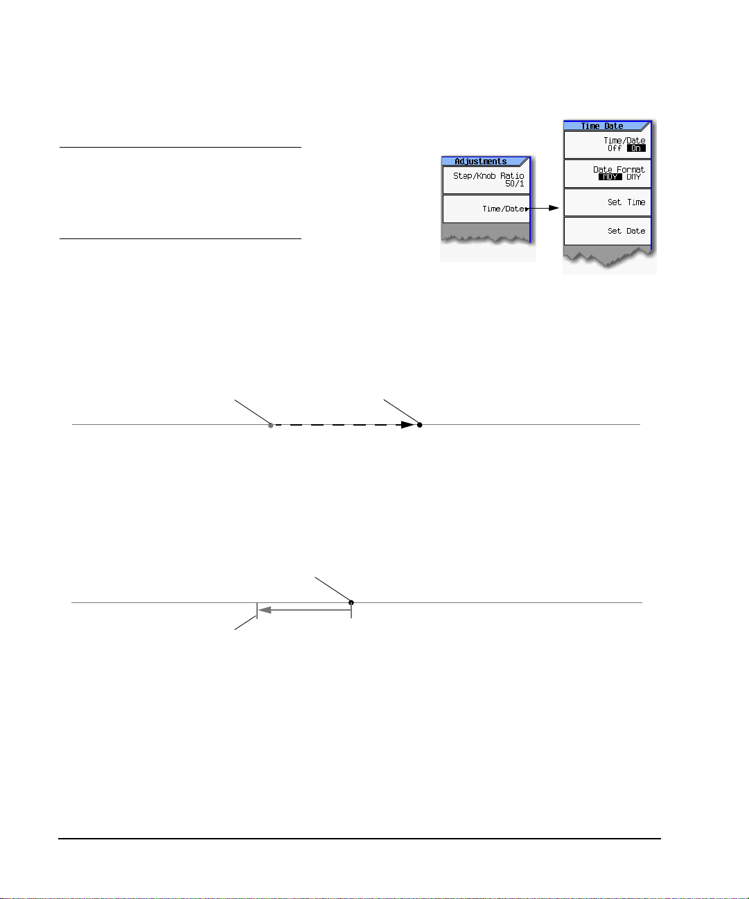
Setting Time and Date
CAUTION
Changing the time or date can
adversely affect the signal
generator’s ability to use time−based
licenses, even if a time−based
license is not installed when you
change the time or date.
tility >
nstrument Adjustments >
The signal generator’s firmware tracks the
time and date, and uses the latest date
and time that has been set as its time/date reference point.
Setting the Time or Date Forward
If you set the time or date forward, be aware that you are using up any installed time- based licenses,
and that you are resetting the signal generator’s time/date reference point. When you set a new time
or date that is later than the signal generator’s current reference point, that date becomes the new
reference point. If you then set the date back, you run the risk described in the next section.
Original time/date reference point
Time
New time/date reference point
Setting the Time or Date Backward
When you set the time back, the signal generator notes that the time has moved back from the
reference point (the latest date that has been set). If you set the time back more than approximately
25 hours, you disable the signal generator’s ability to use time- based licenses, even if there is no
license installed at the time that you set the time back. In this case, you can reenable the signal
generator’s ability to use time- based licenses by returning the date to within 25 hours prior to the
the reference point, or to anytime after the reference point.
Current time/date reference point
Time
Point at which the signal generator can
no longer use time-based licenses.
> 25 hours
If you find you must set the date backward more than approximately 25 hours (when, for example,
the time is mistakenly set ahead) and you wish to use time- based licenses, you must contact Agilent
Technologies for assistance (see page 151).
Upgrading Firmware
For information on new firmware releases, go to http://www.agilent.com/find/upgradeassistant.
18 Agilent N5181A/82A MXG Signal Generators User’s Guide
Page 29

Setting Preferences & Enabling Options
e.
e.
Remote Operat i on Preferences
Remote Operation Preferences
For details on operating the signal generator remotely, refer to the Programming Guide.
Below
page 20
page 20
NOTES
USB is also available. It is not shown in the menu because it requires no
configuration.
For details on using the instrument remotely, see the Programming Guid
Configuring the GPIB Interface
Utility > I/O Config >
Select the desired GPIB languag
For details on each key, use key help
as described on page 23.
Agilent N5181A/82AMXGSignal Generators User’sGuide 19
Page 30

Setting Preferences & Ena b lin g Opt ion s
U
F
a
Remote Operation P ref erences
Configuring the LAN Interface
tility > I/O Config >
See page 20
NOTES
Use a 100Base-T LAN cable to connect the
signal generator to the LAN.
Use a crossover cable to connect the signal
generator directly to a PC.
For details on using the instrument remotely, see
the Programming Guid e.
Listed in the
Programming Guide
Enabling LAN Services : Browser, Sockets, and VXI-11
Utility > I/O Config >
or details on each key, use key help
s described on page23.
20 Agilent N5181A/82A MXG Signal Generators User’s Guide
Enable remote (browser) access to
the instrument’s file system.
Use a browser to control the signal generator.
Page 31

Enabling an Option
There are two ways to enable an option:
• Use the License Manager software utility:
1. Download the utility from www.agilent.com/find/LicenseManager
2. Run the utility and follow the prompts.
• Use SCPI commands, as described in the Programming Guide.
Viewing Options and Licenses
Utility >
Instrument Info >
Setting Preferences & Enabling Options
Enabling an Option
Service Software Licenses
appear here.
Waveform licenses from some
Instrument options appear
here. A check mark means that
an option is enabled.
Agilent N5181A/82AMXGSignal Generators User’sGuide 21
Signal Studio applications appear here.
For details on each key, use key help
as described on page23.
Page 32

Setting Preferences & Ena b lin g Opt ion s
Enabling an Option
22 Agilent N5181A/82A MXG Signal Generators User’s Guide
Page 33

3 Basic Operation
This chapter introduces fundamental front panel operation. For information on remote operation,
refer to the Programming Guide.
• Presetting the Signal Generator, below
• Viewing Key Descriptions, below
• Entering and Editing Numbers and Text on page 24
• Setting Frequency and Power (Amplitude) on page 26
• Configuring a Swept Output on page 27
• Modulating the Carrier Signal on page 34
• Viewing, Saving, and Recalling Data on page 35
• Reading Error Messages on page 42
Presetting the Signal Generator
To return the signal generator to a known state, press either Preset or User Preset.
Preset is the factory preset; User Preset is a custom preset* (see also, page 17).
To reset persistent settings (those unaffected by preset, user preset, or power cycle),
press: Utility > Power On/Preset > Restore Sy st em Defau lts.
*You can create more than one user preset by giving each saved state file a different name (see Figure 3-6 on page 40).
Viewing Key Descriptions
The Help hardkey enables you to display a description of any hardkey or softkey.
To display help text:
1. Press Help.
2. Press the desired key.
The help displays and the key’s normal function does not execute.
Agilent N5181A/82AMXGSignal Generators User’sGuide 23
Page 34

Basic Operation
.
.
9
Entering and Editing Numbers and Text
Entering and Editing Numbers and Text
Entering Numbers and Moving the Cursor
Use the number keys and decimal point to enter numeric data.
Up/down arrow keys increase/decrease a selected (highlighted) numeric value, and move the cursor vertically
Page up/down keys move tables of data up and down within the display area
Left/right arrow keys move the cursor horizontally.
Use the Select hardkey to choose part of an entry, as when entering alpha
characters. In some menus, the
equivalent to the
T o sp ecify a nega tive valu e, enter the
negative sign either before or after
the numeric value (this key is a toggle).
Backspace moves the cursor to the left,
deleting characters as it goes.
For details on each key, see page 23.
Enter softkey.
Select key also acts as a terminator, and is
Note: Rotating the knob increases or
decreases a numeric value, changes a
highlighted digit or character, or steps
through lists or items in a row.
See also, Front Panel Knob Resolution on page 1
Entering Alpha Characters
Note: File names are limited to 25 characters.
Data entry softkeys appear in
various menus. If their meaning
is not clear in context, use the
help key (described on page 23)
to display an explanation. Use
the softkey next to the alpha
table for help on the table.
Selecting data that accepts
alpha characters, displays one of
the menus shown at right.
Use the arrow keys or knob to
to move the cursor
within the active value
rather than within the
alpha table, turn the
alpha table off.
highlight the desired letter, then
press the Select hardkey (or the
softkey next to the alpha table).
Add/edit comments for saved
instrument state files (see page 38).
To correct errors, use Bk Sp or
Clear Text.
To terminate the entry, press the Enter softkey.
A subset of this menu appears for hexadecimal characters. The character menu displays only the
letters A through F (use the numeric keypad for other values).
24 Agilent N5181A/82A MXG Signal Generators User’s Guide
Page 35

Entering and Editing Numbers and Text
Basic Operation
Example: Using a Table Editor
Table editors simplify configuration tasks. The following procedure describes basic table editor
functionality using the List Mode Values table editor.
1. Preset the signal generator: Press Preset.
2. Open the table editor: Press Sweep > More > Config ure List Sweep.
The signal generator displays the editor shown in the following figure.
Active Function Area
Displays the active item as you edit it.
T a ble Editor Name
Current / Total Number of Pages
Highlighting indicates the selected item. To make this the active (editable)
item, either press Select, or simply enter the desired value.
(vector models only)
Table Items
Table items are also
called data fields.
Cursor
T a ble Editor Softkeys
Used to load, navigate, modify, and
store table item values. For details
on each key, use the key help:
Press the Help hardkey and then
the desired key.
Indicates that
another menu
is available; to
display the
second menu,
press More.
3. Highlight the desired item: use the arrow keys or the knob to move the cursor.
4. (Optional) Display the selected item in the active function area: Press Select.
5. Modify the value:
• If the value is displayed in the active function area, use the knob, arrow keys, or numeric
keypad to modify the value.
• If the value is not displayed in the active function area, use the numeric keypad to enter the
desired value (which then appears in the active function area).
6. Terminate the entry:
• If available, press the desired units.
• If units are not displayed, press either Enter (if available) or Select.
The modified item is displayed in the table.
Agilent N5181A/82AMXGSignal Generators User’sGuide 25
Page 36

Basic Operation
Setting Frequency and Power (Amplitude)
Setting Frequency and Power (Amplitude)
Figure 3-1 Frequency and Amplitude Softkeys
See
page 47
page 44
Option
1ER only
To display the next menu, press More.
For details on each key, use key help
as described on page23.
Example: Configuring a 700 MHz, −20 dBm Continuous Wave Output
1. Preset the signal generator.
The signal generator displays its maximum specified frequency and minimum power level (the
front panel display areas are shown on page 7).
2. Set the frequency to 700 MHz: Press Freq > 700 > MHz.
The signal generator displays 700 MHz in both the FREQUENCY area of the display and the active
entry area.
3. Set the amplitude to −20 dBm: Press Amptd > –20 > dBm.
The display changes to −20 dBm in the AMPLITUDE area of the display, and the amplitude value
becomes the active entry. Amplitude remains the active function until you press another function
key.
4. Turn on the RF Output: Press RF On/Off.
The RF Output LED lights, and a 700 MHz, −20 dBm CW signal is available at the RF OUTPUT
connector.
26 Agilent N5181A/82A MXG Signal Generators User’s Guide
Page 37

Configuring a Swept Output
.
rt
.
.
F
Basic Operation
Configuring a Swept Output
The signal generator has two methods of sweeping through a set of frequency and amplitude points:
Step sweep (page 28) provides a linear or logarithmic progression from one selected frequency, or
amplitude, or both to another, pausing at linearly or logarithmically spaced points (steps) along the
sweep. The sweep can progress forward, backward, or manually.
List sweep (page 29) enables you to enter frequencies and amplitudes at unequal intervals, in
nonlinear ascending, descending, or random order. List sweep also enables you to copy the current
step sweep values, include an Arb waveform in a sweep (on a vector instrument), and save list sweep
data in the file catalog (page 37).
Figure 3-2 Sweep Softkeys
During a frequency sweep, the CW frequency does not display; for an amplitude sweep, the amplitude does not display;
for a frequency and amplitude sweep, neither frequency nor amplitude displays.
The selected sweep type determines the displayed parameter.
Progress Bar: very fast sweeps can
appear to sweep randomly or backward
See page 28
Available when
Sweep Type = List
Down sweeps from
stop to start
frequency/amplitude
Up sweeps from sta
to stop
frequency/amplitude
See page 33
See
page 29
See
page 33
or details on each key, use key help as described on page23.
Sweep without waiting for
a trigger at each point.
Point Trigger pauses for the dwel l
time prior to the first sweep.
Trigger on a remote command.
Apply a TTL/CMOS signal to the
Trigger In connector.
Periodically issue a trigger event to
whatever selects it as a source.
Using timer trigger with single
sweep results in a delay pr ior to the
first sweep.
Agilent N5181A/82AMXGSignal Generators User’sGuide 27
Page 38

Basic Operation
e
s
ly.
For details on each key, use key help
Configuring a Swept Output
Step Sweep
Step sweep provides a linear or logarithmic progression from one selected frequency, or amplitude, or
both, to another, pausing at linearly or logarithmically spaced points (steps) along the sweep. The
sweep can progress forward, backward, or manually.
as described on page 23.
Dwell Time = the time that the signal is settled and you can mak
a measurement before the sweep moves to the next point.
(Point-to-point time is the sum of the value set for the dwell plu
processing time, switching time, and settling time.)
Step Sweep and List Sweep dwell times are set indep enden t
Lin = steps equally spaced over the sweep; the output changes
linearly.
Log = step spacing increases logarithmically over the sweep; the
output changes exponentially.
Example: Configuring a Continuous, Linear Step Sw eep
Output: A signal that continuously sweeps from 500 to 600 MHz and from −20 to 0 dBm, with a
dwell time of 500 ms at each of six equally−spaced points.
1. Preset the instrument and open the Sweep/List menu: Press Preset > SWEEP.
Because continuous is the default sweep repeat selection, and linear is the default step spacing
selection, you do not need to set these parameters.
2. Open the step sweep menu: Press Configure Step Sweep.
3. Set the following parameters:
Start frequency 500 MHz: Press Freq Start > 500 > MHz
Stop frequency 600 MHz: Press Freq Stop > 600 > MHz
Amplitude at the beginning of the sweep, −20 dBm: Press Amptd Start >
−20 > dBm
Amplitude at the end of the sweep, 0 dBm: Press Amptd Stop > 0 > dBm.
6 sweep points: Press # Points > 6 > Enter
Dwell time at each point, 500 milliseconds: Press More > Step Dwell > 500 > msec
4. Sweep both frequency and amplitude: Press Return > Return > Sweep > Freq Off On > Amptd Off On.
A continuous sweep begins, from the start frequency/amplitude to the stop frequency/amplitude.
The SWEEP annunciator displays, both the CW frequency and the amplitude display blank
(indicating that both are sweeping), and the progress bar shows the sweep progress.
5. Turn the RF output on: Press RF On/Off.
The RF LED lights, and the continuous sweep is available at the RF Output connector.
28 Agilent N5181A/82A MXG Signal Generators User’s Guide
Page 39

Configuring a Swept Output
For details on each key, use key help
Basic Operation
List Sweep
List sweep enables you to enter frequencies and amplitudes at unequal intervals in nonlinear
ascending, descending, or random order. List sweep also enables you to copy the current step sweep
values, include a waveform in a sweep (on a vector instrument), and save list sweep data in the file
catalog (page 37). Dwell time is editable at each point.
Figure 3-3 List Sweep Configuration Softkeys and Display
as described on page 23.
Displays the selected
sweep type parameters
(see page 30)
See page 28
Available only on vector models,
and
only when Sweep Type = List.
Available only when
waveform entry is selected
Each line defines the
corresponding point in
the sweep. For example,
line 1 defines point 1.
The selected sweep determines which dwell time the signal generator uses. Step Sweep dwell
time is the same at each point; List Sweep dwell time can be different at each point.
Dwell Time = the time that the signal is settled and you can make a measurement before the
sweep moves to the next point.
Point-to-Point Time = the sum of the value set for the dwell plus processing time, switching
time, and settling time.
See page 33
Vector models only
see page 30
Agilent N5181A/82AMXGSignal Generators User’sGuide 29
Page 40

Basic Operation
Configuring a Swept Output
Example: Configur ing a List Sweep Using Step Sweep Data
1. Set up the desired step sweep, but do not turn the sweep on. This example uses the step sweep
configured on page 28.
2. In the SWEEP menu, change the sweep type to list:
Press SWEEP > Sweep Type List Step to highlight List.
The display shows sweep list parameters, as shown below.
3. Open the List Sweep menu: Press More > Configure List Sweep.
4. Clear any previously set values from the menu and load the points defined in the step sweep into
the list: Press More > Preset List > Preset with Step Sweep > Confirm Preset.
The display updates with the values loaded from the step sweep, as shown.
Vector Mo del s:
Presetting the list clears
any previously selected
waveforms.
For information on
selecting a list sweep
waveform, see Example:
Editing List Sweep
Waveforms are available
only on vector models.
Poin ts on page 31.
5. Sweep frequency and amplitude: Press SWEEP (hardkey) > Sweep > Freq Off On > Amptd Off On.
Setting the sweep turns on the sweep function; a continuous sweep begins. On the display, the
SWEEP annunciator appears, and the progress bar shows the progression of the sweep.
6. If not already on, turn the RF output on: Press RF On/Off.
The RF Output LED lights, and a continuous sweep is available at the RF OUTPUT connector.
30 Agilent N5181A/82A MXG Signal Generators User’s Guide
Page 41
Configuring a Swept Output
Basic Operation
Example: Editing List Sweep Points
If you are not familiar with table editors, refer to page 25.
1. Create the desired list sweep. This example uses the list sweep created in the previous example.
2. If sweep is on, turn it off. Editing list sweep parameters with sweep on can generate an error.
3. Set the sweep type to list: Press SWEEP > Sweep Type List Step to highlight List.
4. In the List Mode Values table editor, change the point 1 dwell time (defined in row 1) to 100 ms:
a. Press More > Configure List Sweep.
b. Highlight the point 1 dwell time.
c. Press 100 > msec.
The next item in the table (the frequency value for point 2) highlights.
5. Change the selected frequency value to 445 MHz: Press 445 > MHz.
6. Add a new point between points 4 and 5: Highlight any entry in row 4 and press Insert Row.
This places a copy of row 4 below row 4, creating a new point 5, and renumbers subsequent rows.
7. Shift frequency values down one row, beginning at point 5: Highlight the frequency entry in row
5, then press More > InsertItem.
This shifts the original frequency values for rows 5 and 6 down one row, and creates an entry for
row 8 that contains only a frequency value (the power and dwell time entries do not shift down).
8. Change the still- active frequency value in row 5 to 590 MHz: Press 590 > MHz. The power in row 5
is now the active parameter.
9. Insert a new power value (−2.5 dBm) for point 5, and shift down the original power values for
points 5 and 6 by one row: Press Insert Item >
−2.5 > dBm.
10. To complete the entry for point 8, insert a duplicate of the point 7 dwell time by shifting a copy
of the existing value down: Highlight the dwell time in row 7 and press Insert Item.
11. For an analog instrument, go to step 14. For a vector instrument, continue with step 12.
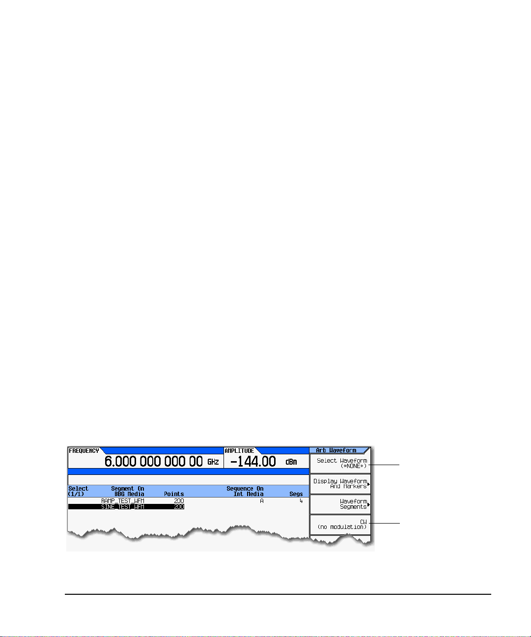
12. Select a waveform for point 2:
a. Highlight the waveform entry for point 2 and press the More > Select Waveform.
The signal generator displays the available waveforms, as shown in the following example.
Either select a waveform,
or
select no modulation.
b. Highlight the desired waveform (in this example, SINE_TEST) and press either the Select
hardkey or the Select Waveform softkey.
Agilent N5181A/82AMXGSignal Generators User’sGuide 31
Page 42

Basic Operation
Configuring a Swept Output
13. As desired, repeat step 12 for the remaining points for which you want to select a waveform. The
following figure shows an example of how this might look.
The empty entry is equivalent to
choosing CW (no modulation).
14. Turn sweep on:
Press Return > Return > Return > Sweep > FreqOff On > AmptdOff On > Waveform Off On.
15. If it is not already on, turn the RF output on:
Press RFOn/Off.
The SWEEP annunciator appears on the display, indicating that the signal generator is sweeping,
and the progress bar shows the progression of the sweep.
Example: Using a Single Sweep
1. Set up either a step sweep (page 28) or a list sweep (page 30).
2. In the List/Sweep menu, set the sweep repeat to single:
Press Sweep Repeat Single Cont to highlight Single.
Sweep does not occur until you trigger it.
Note that the WINIT annunciator appears on the display, indicating that the sweep is waiting to
be initiated.
3. If not already on, turn the RF output on: Press RF On/Off.
4. Initiate the sweep: Press Single Sweep.
A single repetition of the configured sweep is available at the RF Output connector.
As the signal generator sweeps, the SWEEP annunciator replaces WINIT on the display, and the
progress bar shows the progression of the sweep.
At the end of the single sweep, there is no progress bar, and the WINIT annunciator replaces
SWEEP.
32 Agilent N5181A/82A MXG Signal Generators User’s Guide
Page 43

Configuring a Swept Output
Example: Manual Control of Sweep
1. Set up either a step sweep (page 28) or a list sweep (page 30).
2. In the Sweep/List menu, select a parameter to sweep: Press Sweep > parameter.
3. Select manual mode: Press Return > More > Manual Mode Off On.
4. If it is not already on, turn the RF output on: Press RF On/Off.
5. Select the point to output: Press Manu al Point > number > Enter.
6. Use the knob or arrow keys to move from point to point.
Basic Operation
The SWMAN annunciator
indicates that the sweep
is in manual mode.
When you enter the manual
point, the progress bar moves to
and stops at the selected point.
Routing Signals
Sweep > More > More > Route Connectors >
The parameters of the selected sweep point define
the signal available at the RF Output conn ecto r.
Select the signal that you want routed
to each output connector.
For details on each key, use key help
as described on page 23.
Agilent N5181A/82AMXGSignal Generators User’sGuide 33
Page 44

Basic Operation
Modulating the Carrier Signal
Modulating the Carrier Signal
To modulate the carrier signal, you must have both
• an active modulation format
and
• modulation of the RF output enabled
Example
1. Preset the signal generator.
2. Turn on AM modulation: Press AM > AM Off On (requires Option UNT).
You can turn on the modulation format before or after setting signal parameters.
The modulation format generates, but does not yet modulate the carrier signal.
Once the signal generates, an annunciator showing the name of the format appears, indicating
that a modulation format is active.
3. Enable modulation of the RF output: Press the Mod On/Off key until the LED lights.
If you enable modulation without an active modulation format, the carrier signal does not
modulate until you subsequently turn on a modulation format.
Annunciator indicates active AM modulation
AM modulation format on.
A lit LED indicates that any
active modulation format can
modulate the carrier.
NOTE To turn modulation off, press the Mod On/Off key until the LED turns off.
When the Mod On/Off key is off, the carrier signal is not modulated, even with an active
modulation format.
4. To make the modulated carrier available at the RF output connector, press the RF On/Off key until
the LED lights.
See also: “Using Analog Modulation (Option UNT Only)” on page 53
“Using Pulse Modulation (Option UNU)” on page 57
“I/Q Modulation” on page 121
34 Agilent N5181A/82A MXG Signal Generators User’s Guide
Page 45
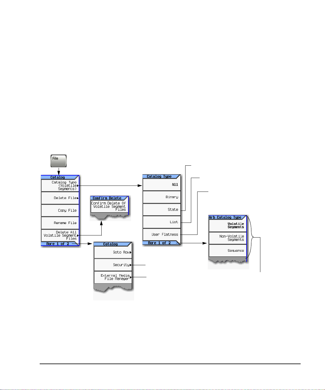
Viewing, Saving, and Recalling Data
Note: Available file types depend on the installed options.
Basic Operation
Viewing, Saving, and Recalling Data
The signal generator enables you to store data as files and view those files in a file catalog. From the
File Catalog (shown in Figure 3- 4), you can delete, copy, or rename a stored file.
• Viewing a Stored File on page 36
• Saving and Recalling Data on page 37
See also:
Work i n g wit h Instrumen t S t a t e F i l e s on page 38
Selecting Internal or External Media on page 41
Storing, Loading, and Playing a Waveform Segment on page 70.
Figure 3-4 File Softkeys
Instrument operating parameters (see page 38).
Sweep data from the List Mode Values table editor.
For details on each key, use key help
as described on page 23.
User flatness calibration corrections.
See page 136
See page41
Note:
If you open the External Media menu wi thout ex terna l
USB media connected, the signal generator displays
the message External Media Not Detected.
Waveform files and their associated marker
and header informatio n.
Agilent N5181A/82AMXGSignal Generators User’sGuide 35
Page 46

Basic Operation
U
k
U
Viewing, Saving, and Recalling Data
Viewing a Stored File
Files Stored in the Signal Generator
1. Press File > Catalog Type > desired catalog.
The files in the catalog appear in alphabetical order. File information includes the file:
•name
•type
•size
• modification date and time
Files Stored on External Media
1. Connect the external media.
The instrument displays the External Media directory.
2. Highlight the USER directory and press Select.
The file directories on the external media appear in alphabetical order, as shown in the following
figure.
se the Page Up and Page Down
eys to see the contents of the
SER directory.
36 Agilent N5181A/82A MXG Signal Generators User’s Guide
Page 47

Viewing, Saving, and Recalling Data
F
a
Basic Operation
Saving and Recalling Data
The method of storing and recalling data depends on the data.
• An instrument state file contains instrument settings. For this type of file, use the Save and Recall
hardkeys, shown in Figure 3- 5 on page 38.
• For other types of data, use the Load/Store softkeys (shown below) that are available through the
menu used to create the file.
or details on each key, use key help
s described on page23.
NOTE File names are limited to 25 characters.
Use this menu to enter the file name,
as described on page24.
Agilent N5181A/82AMXGSignal Generators User’sGuide 37
Page 48

Basic Operation
);
.
u
s
.
For details on each key, use key help
Viewing, Saving, and Recalling Data
Working with Instr ume nt State Files
Figure 3-5 Save and Recall Softkeys
as described on page23.
Instrument settings (states) save to instrument state
memory, which is divided into 10 sequences (0 through 9
each sequence comprises 100 registers (00 through 99)
Delete softkeys in the Save and Recall menus enable yo
to delete the contents of a specific register, or the content
of all sequences in the state file catalog.
The signal generator requires that you confirm a deletion
The following information is not stored in a state file:
System Security Level List Mode Freq Hostname Remot e Language FM Deviation
System Security Level Display List Mode Power IP Address FTP Server PM Deviation
System Security Level State List Mode Dwell Subnet Mask Manual DHCP MAC
Web Server (HTTP) List Mode Sequence Default Gateway VXI- 11 SCPI User Power Correction
Sockets SCPI (TELNET) Display Stat e On/Off ARB Files List Files I/Q Calibration Data
Example: Saving an Instrument State
1. Preset the signal generator and set the following:
• Frequency: 800 MHz • Amplitude: 0 dBm • RF: on
2. (Optional, vector models only) Associate a waveform file with these settings:
a. Press Mode > Dual ARB > Selec t Waveform.
b. Highlight the desired file and press Select Waveform. If the file is not listed, you must first
move it from internal or external media to BBG media, see page 71.
3. Select the desired memory sequence (for this example, 1): Press Save > Select Seq > 1 > Enter.
4. Select the desired register (in this example, 01): Press Select Reg > 1 > Save Reg.
If a waveform is currently selected, saving the instrument state also saves the waveform file
name.
5. Add a descriptive comment to sequence 1 register 01:
Press Add Comment to Seq[1] Reg[01], enter the comment and press Enter. The comment appears in
the Saved States list when you press Recall. If the instrument state has an associated waveform,
entering the waveform name makes it easy to identify which instrument state applies to which
waveform.
38 Agilent N5181A/82A MXG Signal Generators User’s Guide
Page 49

Viewing, Saving, and Recalling Data
Basic Operation
Example: Recalling an Instrument State
1. Preset the signal generator.
2. Press Recall.
The Select Seq softkey shows the last sequence used, and the display lists any states stored in the
registers in that sequence; RECALL Reg is the active entry.
3. Select the desired instrument state:
If the desired state is listed in the currently selected sequence, press desired number > Enter.
If not, press Press SelectSeq > desired number > Enter > RECALL Reg > desired number > Enter.
Example: Recalling an Instrument State and Associated Waveform File
1. Recall the desired instrument state (see previous example).
2. View the waveform file name recalled with the instrument state: press Mode > Dual ARB.
The name is displayed as the selected waveform. Recalling the instrument state recalls only the
waveform name. It does not recreate the waveform file if it was deleted, or load the file into BBG
media if it is in internal or external media.
3. Ensure that the desired waveform file exists, and that it is in BBG media (page 71). If the
waveform file is not in BBG media, performing the next step generates an error.
4. Turn on the waveform file: Press Mode > Dual ARB > ARB Off On.
Example: Recalling an Instrument State and Associated List File
Recalling an instrument state recalls only the list sweep setup. It does not recall the frequency
and/or amplitude values. Because you must load the list file from the file catalog, when you store a
list file, be sure to give it a descriptive name (up to 25 characters).
1. Recall the desired instrument state (see previous example).
2. Recall the desired list file:
a. Press Sweep > More > Configure List Sweep > More > Load/Store.
b. Highlight the desired file and press Load From Selected File > Confirm Load From File.
Agilent N5181A/82AMXGSignal Generators User’sGuide 39
Page 50
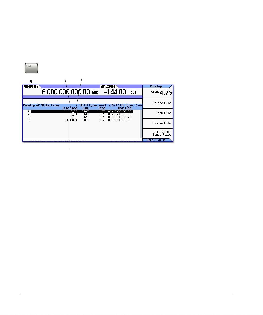
Basic Operation
N
T
Viewing, Saving, and Recalling Data
Moving or Copying a Stored Instrument State
Figure 3-6 Instrument State File Catalog
Sequence Register
User Preset Information
If you rename this file, the signal generator no longer recognizes it as user preset
information.
Defining a User Preset
Set up the instrument as desired, then press User > Save User Preset.
Creating More than One User Preset
Set up several preset conditions under different names; give the one you wish to use the name
USRPRST. To use a different file, rename the current USRPRST, then give the desired file the
name USRPRST.
A user-created state file’s default
name is its memory location.
To move the file, rename it to the
desired sequence and register.
Yo u can not give a file the same
name as an existing file.
Caution
If you rename a state file to
something other than a valid
sequence/register name, the file
does not appear in either the
Save or Recall menu.
ote
o define a user preset, set up the instrument as desired and press User > Save User Preset.
To change a comment on a saved instrument state:
1. Press Save
2. Highlight the desired register
3. Press Edit Comment In Seq[n] Reg [nn].
4. Press Re-SAVE Seq[n] Reg[nn].
This overwrites previously saved instrument state settings with the new comment.
40 Agilent N5181A/82A MXG Signal Generators User’s Guide
Page 51

Selecting Internal or External Media
F
E
d
In the External Media menu (shown below), select the desired storage type.
ile > More >
xternal Media File Manager >
Non-Volatile Storage
Int = Internal
Ext =External; if a memory stick is not connected,
non-volatile storage is not available.
Auto = External if present, otherwise internal is used.
Viewing, Saving, and Recalling Data
File Length (including extension)
Internal Media: 25 characters
External Media: 39 characters
Basic Operation
Save From
Sweep menu
Save menu
Mode menu
Amplitude menu
User Preset menu
Agilent purchase
Pressing Select with file highlighted...
loads list and starts sweep
load instrument state
loads and plays waveform
loads and applies user flatness
loads and executes user preset
installs purchased license
Requires
confirmation
File Type
List
State
Waveform
User Flatness
User Preset
License
Extension
.list
.state
.waveform
.uflat
.uprst
.lic
Using External Media
When you connect storage media to the front panel USB connector, the signal generator displays the
menu shown in the figure below, and the message External USB Storage attached. When you
disconnect the USB media, the message External USB Storage detached displays. When you open
the External Media menu without USB media connected, the signal generator displays the message
External Media Not Detected.
To set the directory that the signal generator will use on the external media:
1. Navigate to the directory. It will display in the path.
2. Press this softkey.
To navigate the directory,
use the Select hardkey an
the Up Directory softkey.
Deletions, backups, and
restores require confirmation.
The signal generator does not format external media, create directories, or change file permissions.
Use a computer to perform these operations.
Agilent N5181A/82AMXGSignal Generators User’sGuide 41
Page 52

Basic Operation
Reading Error Messages
Reading Error Messages
If an error condition occurs, the signal generator reports it to both the front panel display error
queue and the SCPI (remote interface) error queue. These two queues are viewed and managed
separately; for information on the SCPI error queue, refer to the Programming Guide.
Characteristic Front Panel Display Error Queue
Capacity (#errors) 30
Overflow Handling Drops the oldest error as each new error comes in.
Viewing Entries Press: Error > View Next (or Previous) Error Page
Clearing the Queue Press: Error > ClearError Queue(s)
a
Unresolved Erro rs
No Er rors
a
Errors that must be resolved. For example, unlock.
Re- reported after queue is cleared.
When the queue is empty (every error in the queue has been read, or the queue is cleared), the
following message appears in the queue:
No Error Message (s) i n Que ue 0 of 0
Error Message Format
In the front panel display
error queue, error
messages display on an
enumerated (“1 of N”)
basis.
Error messages appear in the lower-left corner
of the display as they occur.
Error Number
Error Message
Error Desc ription
(May be truncated on the display)
−222 Data out of range; value clipped to lower limit.
Indicates that the user has entered a deviation, depth, or internal
source frequency that is beyond the specific limits
Explanation is provided in the Error Message file (see page 148)
The annunciator indicates an unviewed message.
(This is not displayed on the instrument)
new indicates a message generated
since messages were last viewed.
Message number and longer description
42 Agilent N5181A/82A MXG Signal Generators User’s Guide
Page 53

4 Optimizing Performance
Before using this information, you should be familiar with the basic operation of the signal generator.
If you are not comfortable with functions such as setting the power level and frequency, refer to
Chapter 3, “Basic Operation,” on page 23 and familiarize yourself with the information in that
chapter.
• Using User Flatness Correction on page 44
• Using Unleveled Operating Modes on page 47
• Using an Output Offset, Reference, or Multiplier on page 49
Agilent N5181A/82AMXGSignal Generators User’sGuide 43
Page 54

Optimizing Performance
For details on each key, use key help
Using User Flatness Correction
Using User Flatness Correction
User flatness correction enables you to adjust the RF output amplitude for up to 1601 sequential
linearly or arbitrarily spaced frequency points to compensate for external losses in cables, switches,
or other devices.
You can create and save individual user flatness correction tables, which enables you to recall
different correction arrays for various test setups or frequency ranges (see page 46).
Figure 4-1 User Flatness Correction Softkeys
as described on see page23.
Confirm
Basic Procedure
1. Create a user flatness array: Enter the user flatness correction values.
2. Optionally, save the user flatness correction data.
3. Apply user flatness correction to the RF Output.
44 Agilent N5181A/82A MXG Signal Generators User’s Guide
Page 55

Optimizing Performance
Using User Flatness Correction
Example: A 500 MHz to 1 GHz Flatn ess Correction Arra y with 10 Correction Values
Create the User Flatness Array
1. Configure the signal generator:
a. Preset the signal generator.
b. Open the User Flatness table editor and preset the cal array:
Press Amptd > More > User Flatness > Configure Cal Array > More > Preset List > Confirm Preset.
c. In the Step Array menu, enter the desired flatness- corrected frequencies:
Press Configure Step Array >
Freq Start > 500 > MHz >
Freq Stop > 1 > GHz >
# of Points > 10 > Enter
d. Populate the user flatness correction array with the step array configured in the previous
step:
Press Return > Load Cal Array From Step Array > Confirm Load From Step Data.
e. Set the output amplitude to 0 dBm.
f. Turn on the RF output.
2. Connect the power meter to the RF output and manually enter the correction values:
a. Open the User Flatness table editor and highlight the frequency value in row 1:
Press More > User Flatness > Configure Cal Array.
The RF output changes to the frequency value of the table row containing the cursor.
b. Note the value measured by the power meter.
c. Subtract the measured value from 0 dBm
d. Highlight the correction value in row 1.
e. Press Select > the difference calculated in step c > Enter.
The signal generator adjusts the output amplitude based on the correction value entered.
f. If the power meter does not read 0 dBm, adjust the value in step e until it does.
g. Highlight the frequency value in the next row.
h. Repeat steps b through g for this and the remaining rows.
The user flatness correction array title displays User Flatness:, without a name, indicating that
the current user flatness correction array data has not been saved to the file catalog.
Agilent N5181A/82AMXGSignal Generators User’sGuide 45
Page 56

Optimizing Performance
Using User Flatness Correction
Optional: Save the User Flatness Correction Data
1. Press Load/Store > Store to File.
2. Enter a file name (for this example, FLATCAL1) and press Enter.
The user flatness correction array file is now stored in the file catalog as a UFLT file. Any user
flatness correction files saved to the catalog can be recalled, loaded into the correction array, and
applied to the RF output to satisfy specific RF output flatness requirements.
3. Press Return.
Enable the Flatness Correction at the RF Output
• Press Return > Flatness Off On.
The UF annunciator appears in the AMPLITUDE area of the display, and the correction data in the
array is applied to the RF output.
Recalling and Applying a User Flatness Correction Array
The following example assumes that a user flatness correction array has been created and stored. If
not, perform the Example: A 500 MHz to 1 GHz Flatness Correction Array with 10 Correction
Val ues on page 45.
1. Preset the signal generator.
2. Recall the desired User Flatness Correction file:
a. Press AMPTD > More > User Flatness > Configure Cal Array > More > Preset List > Confirm Preset.
b. Press More > Load/Store.
c. Highlight the desired file.
d. Populate the user flatness correction array with the data contained in the selected file:
Press Load From Selected File > Confirm Load From File.
The user flatness correction array title displays User Flatness: Name of File.
3. Apply the correction data in the array to the RF output: Press Return > Flatness Off On.
46 Agilent N5181A/82A MXG Signal Generators User’s Guide
Page 57

Using Unleveled Operating Modes
Figure4-2 Power Search and ALC Off Softkeys
Available only when
ALC = Off
Available only when
Power Search = Span
Available only when
Power Search = Span,
and
Span Type = User
Using Unleveled Operating Modes
Auto: The calibration routine executes whenever
output frequency or amplitude changes.
Span: Pressing Do Power Search executes the
power search calibration routine once over a
selected frequency range.
The corrections are stored and used whenever you
tune the signal generator to within the calibrated
frequency range.
Optimizing Performance
For details on each key, use key help
as described on see page23.
ALC Off Mode
Turning ALC off deactivates the signal generator’s automatic leveling circuitry, enabling you to
measure the output at a specific point in a test setup and adjust as required for the desired power
level at that point. Turning ALC off is useful when the modulation consists of very narrow pulses
that are below the pulse width specification of the ALC, or when the modulation consists of slow
amplitude variations that the automatic leveling would remove.
1. Preset the signal generator.
2. Set the desired frequency.
3. Set the desired amplitude.
4. Connect the power meter to the point at which you want a specific power level.
5. Turn the RF output on.
6. Deactivate the signal generator’s automatic leveling control: Press AMPTD > ALC Off On to
highlight Off.
7. Adjust the signal generator’s amplitude until the power meter measures the desired level.
Agilent N5181A/82AMXGSignal Generators User’sGuide 47
Page 58

Optimizing Performance
Using Unleveled Operating Modes
Power Search Mo de
Refer to Figure 4-2 on page 47. Power search executes a routine that temporarily activates the ALC,
calibrates the power of the current RF output, and then disconnects the ALC circuitry.
NOTE For the power search routine to execute, RF must be on and ALC must be off.
Example: Automatic Power S earch
1. Preset the signal generator.
2. Set the desired frequency.
3. Set the desired amplitude.
4. Turn the RF output on.
5. Deactivate the signal generator’s automatic leveling control:
Press AMPTD > ALC Off On to highlight Off
Deactivating the signal generator’s automatic leveling control is a significant instrument change
that automatically initiates a power search.
When set to Auto, power search automatically executes when a significant instrument setting changes.
The Do Power Search feature enables you to execute a power search to compensate for other changes,
such as temperature drift or a change in the external input.
48 Agilent N5181A/82A MXG Signal Generators User’s Guide
Page 59

Using an Output Offset, Reference, or Multiplier
Optimizing Performance
Using an Output Offset, Reference, or Multiplier
Setting an Output Offset
Using an output offset, the signal generator can output a frequency or amplitude that is offset
(positive or negative) from the entered value.
RF Output = entered value − offset value
Displayed Value = output frequency + offset value
To se t an offset:
• Frequency: Press Freq > Freq Offset > offset value > frequency unit.
• Amplitude: Press Amptd > More > Amptd Offset > offset value > dB.
Indicates that an offset is on
Examples
Parameter
Entered (and displayed) Value: 300 MHz 300 MHz 2 GHz The entered value must be positive.
Offset: 50 MHz −50 MHz −1 GHz An offset value can be positive or negative.
Output Frequency: 250 MHz 350 MHz 3 GHz
Example#1Example#2Example
#3
Comments
The signal generator alerts you if the
output frequency or amplitude is out of range.
When using the signal generator as a local oscillator (LO), you can use the offset to display the
frequency of interest, as illustrated below:
Antenna tuned to 1321 MHz
RF Amplifier
Mixer
Output Frequency = 1000 MHz
Signal Generator
(local oscillator)
Filter
IF = 321 MHz
Selected Offset
321 MHz
−679 MHz
Agilent N5181A/82AMXGSignal Generators User’sGuide 49
IF Amplifier
IF Output
321 MHz
SIgnal Generator Display
1321 MHz (Antenna Frequency)
321 MHz (IF Output)
Page 60

Optimizing Performance
Using an Output Offset, Reference, or Multiplier
Setting an Output Reference
Using an output reference, the signal generator can output a frequency or amplitude that is offset
(positive or negative) by the entered value from a chosen reference value.
RF Output = reference value + entered value
To set a reference:
1. Set the frequency or amplitude to the value you want as the output reference level.
2. Frequency: Press Frequency > Freq Ref Set
The frequency displays 0.00 Hz, indicating that this is the RF output frequency “zero level.”
All frequencies entered are interpreted as being relative to this reference frequency.
Amplitude: Press Amptd > More > Amptd Ref Set
The amplitude displays 0.00 dB, indicating that this is the RF output amplitude “zero level.”
All amplitudes entered are interpreted as being relative to this reference amplitude.
Indicates that a reference is on
Examples
Parameter
Reference: 50 MHz 50 MHz 2 GHz A reference value must be positive.
Entered (and displayed) Value: 2 MHz −2 MHz −1 GHz The ent ered value can be p ositive or ne gative.
Output Frequency: 52 MHz 48 MHz 1 GHz
Example#1Example#2Example
#3
Comments
The signal generator alerts you if the output frequency or
amplitude is out of range.
To set a new frequency or amplitude reference, turn the frequency reference off, and then follow the
steps above.
50 Agilent N5181A/82A MXG Signal Generators User’s Guide
Page 61

Using an Output Offset, Reference, or Multiplier
r
Optimizing Performance
Setting a Frequency Multiplier
Using a frequency multiplier, the signal generator can display a frequency that is the multiple
(positive or negative) of the output value.
Displayed Value = multiplier value × output frequency
Output Frequency = displayed value ÷ multiplier value
To set a frequency multiplier:
1. Press Frequency > Freq Multiplier > multiplier value > x.
2. Set the desired frequency.
The display equals the output frequency times the multiplier value.
Indicates that a frequency multiplier is on
Examples
Parameter
Frequency Multiplier: 3 −3 4 A multiplier value can be positive or negative.
Entered (and displayed) Value: 600 MHz −600 MHz 8 GHz
Output Frequency: 200 MHz 200 MHz 2 GHz
Example#1Example#2Example
#3
Comments
The signal generator alerts you if the output frequency is
out of range.
When using the signal generator as the input to a system, you can set the frequency multiplier so
that the signal generator displays the output of the system, as illustrated below using a doubler:
Signal Generator Doubler
Input = 2 GHz
X2
Output = 4 GHz
Selected
Multiplier
2
Agilent N5181A/82AMXGSignal Generators User’sGuide 51
Entered/Displayed
Frequency
4 GHz
Signal Generato
Output
2 GHz
Page 62

Optimizing Performance
Using an Output Offset, Reference, or Multiplier
When measuring mixers, the frequency multiplier and frequency offset are often used together. In the
upconverter example below, the multiplier is set to −1 and the offset is set to 3 GHz so that the
signal generator displays f
RF
.
Mixer
fRF = 2200 - 2400 MHz
fLO = 800 − 600 MHz
Signal Generator
(local oscillator)
fIF = 3000 MHz
Selected
Multiplier
−1
−1
Selected
Offset
3000 MHz
3000 MHz
Entered/Displayed
Frequency
(fRF)
2200 MHz
2400 MHz
Signal Generator
Output (fLO)
800 MHz
600 MHz
52 Agilent N5181A/82A MXG Signal Generators User’s Guide
Page 63

5 Using Analog Modulation (Option UNT Only)
F
a
Before using this information, you should be familiar with the basic operation of the signal generator.
If you are not comfortable with functions such as setting the power level and frequency, refer to
Chapter 3, “Basic Operation,” on page 23 and familiarize yourself with the information in that
chapter.
• The Basic Procedure on page 54
• Using an External Modulation Source on page 55
• Removing a DC Offset on page 55
Figure 5-1 Analog Modulation Softk eys
See
page 55
or details on each key, use key help
s described on see page23.
Agilent N5181A/82A MXG Signal Generators User’s Guide 53
See
page 55
See
page 55
Page 64

Using Analog Modulation (Option UNT Only)
The Basic Procedure
The Basic Procedure
1. Preset the signal generator.
2. Set the carrier (RF) frequency.
3. Set the RF amplitude.
4. Configure the modulation:
AM FM ΦM
a. Press AM
b. Set the AM type (linear or exponential):
AMType to highlight desired type
c. Set the depth:
AMDepth > value > %
d. Set the rate:
AM Rate > value > frequency unit
a. Press FM/ΦM
b. Set the deviation:
FM Dev > value > frequency unit
c. Set the rate:
FM Rate > value > frequency unit
a. Press FM/ΦM > FM ΦM
b. Set the BW (normal or high):
FM ΦM to highlight desired type
c. Set the deviation:
ΦMDev > value > pi rad
d. Set the rate:
ΦM Rate > value > frequency unit
5. Turn on the modulation:
AM FM ΦM
AM Off On softkey to On FM Off On softkey to On ΦM Off On softkey to On
The appropriate modulation annunciator displays, indicating that you enabled modulation.
6. Turn on the RF output.
The RF output LED lights, indicating that the signal is transmitting from the RF output connector.
If the modulation does not seem to be working properly, refer to “No Modulation at the RF Output”
on page 143.
See also “Modulating the Carrier Signal” on page 34.
54 Agilent N5181A/82A MXG Signal Generators User’s Guide
Page 65

Using an External Modulation Source
Currently selected modulation.
Select to use external modulation
Rear panel inputs are
described on page 9
AM input
FM or ΦM input
Default
Using Analog Modulation (Option UNT Only)
Using an External Modulation Source
Removing a DC Offset
To eliminate an offset in an externally applied FM or ΦM signal, perform a DCFM or DCΦM
Calibration.
NOTE You can perform this calibration for internally generated signals, but DC offset is not usually
1. Set up and turn on the desired modulation.
2. Press FM/ΦM > More > DCFM/DCΦM Cal.
Performing the calibration with a DC signal applied removes any deviation caused by the DC signal,
and the applied DC level becomes the new zero reference point. When you disconnect the DC signal,
perform the calibration again to reset the carrier to the correct zero reference.
Agilent N5181A/82A MXG Signal Generators User’s Guide 55
a characteristic of an internally generated signal.
Page 66

Using Analog Modulation (Option UNT Only)
Using an External Modulation Source
56 Agilent N5181A/82A MXG Signal Generators User’s Guide
Page 67

6 Using Pulse Modulation (Option UNU)
Before using this information, you should be familiar with the basic operation of the signal generator.
If you are not comfortable with functions such as setting the power level and frequency, refer to
Chapter 3, “Basic Operation,” on page 23 and familiarize yourself with the information in that
chapter.
• Pulse Characteristics on page 59
• The Basic Procedure on page 61
• Example on page 61
Agilent N5181A/82AMXGSignal Generators User’sGuide 57
Page 68

Using Pulse Modulation (Option UNU)
1
l
F
a
D
r
N
I
Figure 6-1 Pulse Softkeys
etermines how the signal generator
esponds to an external pulse signal.
ormal = high state.
nvert = low state.
See also, page 9
and page 10
See page 61
See page 6
Low = settled
Latency from the externa
pulse input to the pulse
sync output ≈ 50−60 ns.
Width Period
50 ns > 50 ns
20 ns ≤ 50 ns
or details on each key, use key help
s described on page23.
Select the signal that you want
routed to each output connector.
58 Agilent N5181A/82A MXG Signal Generators User’s Guide
TTL signal
Page 69

Pulse Characteristics
R
Using Pulse Modulation (Option UNU)
Pulse Characteristics
NOTE When using very narrow pulses that are below the signal generator’s ALC pulse width
specification, or leveled pulses with an unusually long duty cycle, it is often useful to turn
ALC off (see page 47).
Pulse Source Type
Square
Free Run
(default)
Triggered Internal pulse train User Defined
Adjustable
Doublet
Trigger
Doublet
Gated Internal gated pulse train User Defined
External
a
All delays, widths, and periods have a resolution of 10 ns.
b
A signal at the rear panel pulse connector must be held high for at least 20 ns to trigger an internally generated pulse.
Internal free run pulse train with
50% duty cycle.
Internal free run pulse train User Defined User Defined
Two internal pulse trains for each
trigger event.
Two internal pulse trains for each
trigger event.
External pulse signal at the rear
panel Pulse connector
Determined by
user defined rate.
a
Peri od
Width & Delay
User Defined:
First pulse is relative to the
rising edge of trigger signal.
Second pulse is relative to the
rising edge of first pulse.
See Figure 6- 2 on page 60
The first pulse follows the
trigger sig nal.
Second pulse is user defined.
See Figure 6- 3 on page 60
a
Uses T rigger Event
✓
✓
✓
✓
b,
ear panel inputs are described on page 9
External pulse input
Agilent N5181A/82AMXGSignal Generators User’sGuide 59
Page 70
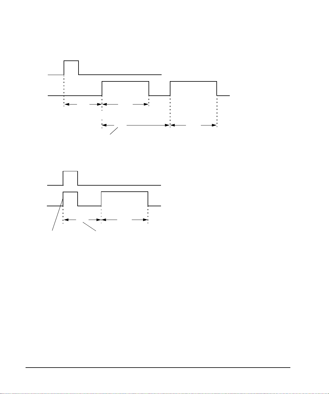
Using Pulse Modulation (Option UNU)
T
t
Pulse Characteristics
Figure 6-2 Adjustable Doublet
External
Trigger
RF Output
Delay
he delay of the first pulse is measured from
he leading edge of the external trigger signal.
Figure 6-3 Trigger Doublet
External
Trigger
Width
Delay
The delay of the second pulse is me asured fro m
the leading edge of the first pulse.
Width
RF Output
Delay Width
The first pulse follows the
external trigger signal.
The delay of the second pulse is me asured fro m
the leading edge of the external trigger signal.
60 Agilent N5181A/82A MXG Signal Generators User’s Guide
Page 71

Using Pulse Modulation (Option UNU)
The Basic Proc edure
The Basic Procedure
1. Preset the signal generator.
2. Set the carrier (RF) frequency.
3. Set the RF amplitude.
4. Configure the modulation:
a. Set the pulse source: Press Pulse > Pulse Source > selection
b. Set the parameters for the selected pulse source:
Square Free Run (default) Triggered Adj ust abl e Doublet Trigger Doublet Gated External
Pulse Rate
Pulse Period Pulse Period
Pulse Delay Pulse Delay Pulse Delay Pulse Delay
Pulse Width Pulse Width Pulse Width Pulse Width Pulse Width
Pulse 2 Delay
Pulse 2 Width
5. Turn on the modulation: Pulse Off On softkey to On.
The the PULSE annunciator lights, indicating that you enabled modulation.
6. Output the modulated signal from the signal generator: Press the front panel RF On Off key.
The RF output LED lights, indicating that the signal is transmitting from the RF output connector.
See also, “Modulating the Carrier Signal” on page 34.
Example
The following example uses the factory preset pulse source and delay.
Output: A 2 GHz, 0 dBm carrier modulated by a 24 µs pulse that has a period of 100 µs.
1. Preset the signal generator.
2. Set the frequency to 2 GHz.
3. Set the amplitude to 0 dBm.
4. Set the pulse period to 100 microseconds: Press Pulse > Pulse Period > 100 > usec.
5. Set the pulse width to 24 microseconds: Press Pulse > Pulse Width > 24 > usec
6. Turn on both the pulse modulation and the RF output.
The PULSE annunciator displays and the RF output LED lights.
If the modulation does not seem to be working properly, refer to “No Modulation at the RF Output”
on page 143.
Agilent N5181A/82AMXGSignal Generators User’sGuide 61
Page 72

Using Pulse Modulation (Option UNU)
Example
62 Agilent N5181A/82A MXG Signal Generators User’s Guide
Page 73

7 Basic Digital Operation—No BBG Option Installed
Before using this information, you should be familiar with the basic operation of the signal generator.
If you are not comfortable with functions such as setting power level and frequency, refer to Chapter
3, “Basic Operation,” on page 23 and familiarize yourself with the information in that chapter.
See Also: “Adding Real- Time Noise to a Dual ARB Waveform” on page 130
Agilent N5181A/82AMXGSignal Generators User’sGuide 63
Page 74

Basic Digital Operation—No BBG Option Installed
F
a
I/Q Modulation
I/Q Modulation
The following factors contribute to the error vector magnitude:
• Differences in amplitude, phase, and delay between the I and Q channels
•DC offsets
The I/Q menu provides adjustments to compensate for some of the differences in the I and Q signals
or to add impairments.
See also, “Modulating the Carrier Signal” on page 34.
Figure7-1 I/Q Display and Softkeys
This panel displays the current status and settings
This panel displays the external
I/Q signal routing.
of the I/Q adjustments. Grey indicates I/Q
adjustments are off.
Sets the dc offset
or details on each key, use key help
s described on page 23.
Offsets the phase of the Q signal relative to the phase of the
I signal. The quadrature adjustment key is calibrated in units
of degrees. This adjustment is not calibrated.
The following table shows common uses for the adjustments.
Table 7-1 I/Q Adjustments Uses
I/Q Adjustment Effect Impairment
Offset Carrier Feedthrough dc offset
Quadrature Angle
64 Agilent N5181A/82A MXG Signal Generators User’s Guide
EVM error phase skew
I/Q Images I/Q path delay
Page 75

Basic Digital Operation—No BBG Option Installed
I/Q Modulation
Configuring the Front Panel Inputs
The Agilent MXG accepts externally supplied analog I and Q signals through the front- panel I Input
and Q Input for modulating onto the carrier.
1. Connect I and Q signals to the front panel connectors.
a. Connect an analog I signal to the signal generator’s front- panel I Input.
b. Connect an analog Q signal to the signal generator’s front- panel Q Input.
2. Turn on the I/Q modulator: Press I/Q Off On to On.
3. Configure the RF output:
a. Set the carrier frequency.
b. Set the carrier amplitude.
c. Turn the RF output on.
4. Make adjustments to the I/Q signals (page 64) as needed.
Agilent N5181A/82AMXGSignal Generators User’sGuide 65
Page 76

Basic Digital Operation—No BBG Option Installed
I/Q Modulation
66 Agilent N5181A/82A MXG Signal Generators User’s Guide
Page 77

8 Basic Digital Operation (Option 651/652/654)
Before using this information, you should be familiar with the basic operation of the signal generator.
If you are not comfortable with functions such as setting power level and frequency, refer to Chapter
3, “Basic Operation,” on page 23 and familiarize yourself with the information in that chapter.
The features described in this chapter are available only in vector signal generators with Option 651,
652, or 654.
• Wave form F ile Basi c s on page 68
• Storing, Loading, and Playing a Waveform Segment on page 70
• Setting the Baseband Frequency Offset on page 72
• Wave form Seque n c e s on page 74
• Saving a Waveform’s Settings & Parameters on page 78
• Using Waveform Markers on page 82
• Triggering a Waveform on page 98
• Clipping a Waveform on page 105
• Scaling a Waveform on page 114
• I/Q Modulation on page 121
See Also: “Adding Real- Time Noise to a Dual ARB Waveform” on page 130
Agilent N5181A/82AMXGSignal Generators User’sGuide 67
Page 78

Basic Digital Operation (Option 651/652/654)
Waveform File Basics
Waveform File Basics
There are two types of waveform files:
•A segment is a waveform file that you download to the signal generator.
For information on creating and downloading waveform files, refer to the Programming Guide.
•A sequence is a file you create in the signal generator that contains pointers to one or more
waveform files (segments, other sequences, or both).
For information on creating sequences, see page 74.
Signal Generator Memory
The signal generator has two types of memory:
• Volatile memory, baseband generator (BBG) media, where waveform files are played from or
edited.
• Non- volatile memory, either internal (int) or external (USB) media, where waveform files are
stored.
Dual ARB Player
The dual ARB waveform player enables you to play, rename, delete, store, and load waveform files in
addition to building waveform sequences. The dual ARB waveform player also provides markers
(page 82), triggering (page 98), clipping (page 105), and scaling (page 114) capabilities.
Most procedures in this section start from the Dual ARB menu, shown below.
68 Agilent N5181A/82A MXG Signal Generators User’s Guide
Page 79

Figure 8-1 Dual ARB Softkeys
4
If you set the ARB sample clock when the dual A RB
B
F
a
.
Note: This is second of
or details on each key, use key help
s described on page23.
three Arb menus.
Note: This is the
first of three
Arb menus.
page 70
page 98
page 82
Basic Digital Operation (Option 651/652/654)
is off, the new settin g is appl ied when th e d ual AR
player is turned on; this setting survives toggling
the Dual ARB player off and on.
page 130
page 114
page 72
Waveform File Basics
page 74
page 78
Note: This is third of
three Arb menus
page 10
page 11
page 10
Agilent N5181A/82AMXGSignal Generators User’sGuide 69
Page 80

Basic Digital Operation (Option 651/652/654)
F
a
Storing, Loading, and Playing a Waveform Segment
Storing, Loading, and Playing a Waveform Segment
See also, Viewing, Saving, and Recalling Data on page 35.
Figure 8-2 Waveform Segment Softkeys
Note: When a sequence is highlighted, this key name
changes to Show Waveform Sequence Contents.
or details on each key, use key help
s described on page23.
See page82
Use the arrow keys or kn ob to
highlight a letter or character
Storing/Renaming a Waveform Segment to Non-Volatile Memory (Internal or External Media)
Use the following steps to store a copy of a file in BBG memory to the currently selected media
(page 41). If you have not downloaded a waveform segment, either refer to the Programming Guide,
or use one of the factory- supplied segments.
1. Press Mode > Dual ARB > Select Waveform > Waveform Segments.
2. In the Segment On BBG Media column, highlight any waveform segment.
3. Press Load Store to highlight Store.
4. Highlight the waveform segment you want to store.
5. Optionally rename the segment.
If there is already a copy of this segment in the currently selected media and you do not want to
overwrite it, rename the waveform segment before you store it:
a. Press More > Rename Segment > Clear Text.
b. Enter a name for the waveform segment.
c. Press Enter > More.
d. Highlight the waveform segment that was renamed.
6. Press Sto re Se g ment to currently selected Media.
70 Agilent N5181A/82A MXG Signal Generators User’s Guide
Page 81

Basic Digital Operation (Option 651/652/654)
Storing, Loading, and Playing a Waveform Segment
7. R epe at Step 4 through Step 6 for all segments that you want to store.
To save all segments from BBG media to the currently selected media, press
Store All to currently selected Media.
Loading a Waveform Segment into BBG Media (Volatile Memory)
Waveform segments must reside in BBG media before they can be played, edited, or included in a
sequence. Cycling power or rebooting the signal generator deletes the files in BBG media.
NOTE Each time the instrument powers up, two factory- supplied segments are automatically
created in BBG media: RAMP_TEST_WFM and SINE_TEST_WFM.
1. Press Mode > Dual ARB > Select Waveform > Waveform Segments.
2. Press Load Store to highlight Load.
3. Highlight the waveform segment you want to load.
4. If there is already a copy of this segment in the currently selected media and you do not want to
overwrite it, rename the waveform segment before you load it (refer to the previous procedure).
5. Press Load Segment From currently selected Media.
To load all files from the currently selected media into BBG media, press
Load All From currently selected Media.
Playing a Waveform Segment
1. Press Mode > Dual ARB > Select Waveform.
2. In the Segment on BBG Media column, highlight the waveform segment you want to play.
3. Press Select Waveform > ARB Off On to On.
This plays the selected waveform segment. During the waveform segment generation, both the I/Q
and ARB annunciators turn on, and the waveform modulates the RF carrier.
Annunciators display with active waveform (ARB On)
Current waveform selection
4. Configure the RF Output:
a. Set the RF carrier frequency.
b. Set the RF output amplitude.
c. Turn on the RF output.
The waveform segment is now available at the signal generator’s RF OUTPUT connector.
Agilent N5181A/82AMXGSignal Generators User’sGuide 71
Page 82

Basic Digital Operation (Option 651/652/654)
p
Setting the Baseband Frequency Offset
Setting the Baseband Frequency Offset
Figure8-3 Baseband Frequency Offset Softke y
The settings in this menu
can be stored to the file
header, see page 78.
See page 130
See page114
Frequency offset setting.
For details on each key, use key hel
as described on page 23.
The baseband frequency offset enables you to shift the baseband frequency up to ±50 MHz within the
BBG 100 MHz signal bandwidth, depending on the signal generator’s baseband generator option.
Common uses for the offset feature include:
• offsetting the carrier from any LO feedthrough (carrier signal spur at the carrier frequency)
• sum the baseband signal with external I and Q inputs to create a multicarrier signal
• use the signal generator’s I/Q signal as an IF
NOTE Changing the baseband frequency offset may cause a DAC over range condition that
generates error 628, Baseband Generator DAC over range. When this occurs, reduce the
waveform runtime scaling value (page 114).
The baseband frequency offset value is one of the file header parameters (page 78), which means you
can store this value with the waveform. When you select a waveform with a stored frequency offset
value, the signal generator changes the current value to match the stored file header value. If there
is no stored baseband offset frequency value for the current waveform, the signal generator uses the
last set frequency offset value.
You can also use the Save function (page 35) to store this value as part of the signal generator setup.
When you Recall a setup stored with the Save function, the baseband frequency offset value becomes
the current instrument setting value, disregarding the stored file header value.
72 Agilent N5181A/82A MXG Signal Generators User’s Guide
Page 83

Basic Digital Operation (Option 651/652/654)
Setting the Baseband Frequency Offset
Use the following steps to offset the carrier from LO/carrier feedthrough. This example uses the
factory supplied waveform, SINE_TEST_WFM. To view the output for this example, connect the RF
OUTPUT of the signal generator to the input of a spectrum analyzer.
1. Select and play the waveform.
a. Press Mode > Dual ARB > Selec t Waveform.
b. In the Segment On BBG Media column, select SINE_TEST_WFM.
c. Press Select Waveform.
2. Generate the waveform: Press ARB Off On to On.
3. Configure the carrier signal:
a. Set the carrier signal to 1 GHz.
b. Set the amplitude to 0 dBm.
c. Turn on the RF OUTPUT.
4. Press ARB Setup > Baseband Freque ncy Offset > 20 MHz.
The modulated RF signal is now offset from the carrier frequency by 20 MHz as shown in the
following figures.
Modulated carrier with 0 Hz
baseband freque nc y off set
Modulated carrier with 20 MHz
baseband frequency offset
LO/carrier feedthrough
Spectrum analyzer set to a span of 100 MHz
Modulated RF signal
Agilent N5181A/82AMXGSignal Generators User’sGuide 73
Page 84

Basic Digital Operation (Option 651/652/654)
Waveform Sequences
Wavef orm S equences
Figure 8-4 Waveform Sequence Softkeys
Mode >
Dual ARB >
To display this softkey, highlight a waveform sequence
Sequence name
Sequence contents
see page 95
For details on each key, use key help
as described on page23.
A waveform sequence is a file that contains pointers to one or more waveform segments or other
waveform sequences, or both. This lets the signal generator play multiple waveform segments, or
other sequences, or both thereby eliminating the need to stop waveform playback just to select
another waveform.
The segments that a waveform sequence points to are not automatically stored when you store the
sequence; you must also store the individual segments or they are lost when you turn off or reboot
the signal generator. If the segments are located in internal/external media, you must load them into
BBG media prior to selecting a waveform sequence. If you attempt to play a sequence without the
segments loaded into BBG media, the signal generator reports: ERROR: 629, File format invalid.
If this happens and the segments are not stored in internal/external media, you must recreate the
segments using the same file names that the sequence points to before you can play the sequence.
74 Agilent N5181A/82A MXG Signal Generators User’s Guide
Page 85

Basic Digital Operation (Option 651/652/654)
Waveform Sequ ences
Creating a Sequence
A waveform sequence can contain up to 1,024 segments and have both segments and other sequences
(nested sequences). The signal generator lets you set the number of times the segments and nested
sequences repeat during play back. But there is a difference between repeating a segment versus
repeating a nested sequence. Each segment can repeat up to 65,535 times, but no matter how many
times a segment repeats, it counts as a single segment. However each repetition of a nested sequence
counts as additional segments.
Segment 1
Sequence A
Waveform
Sequence
Sequence B
Segment 2
Sequence A
repeated 4x
Segment 3
8 Segments
The maximum number of times that a nested sequence can repeat is based on the number of
segments in the nested sequence and the remaining number of allowed segments (1,024). For
example, with a sequence that contains 24 segments and one nested sequence with 4 segments, the
nested sequence is limited to 250 repetitions:
24 + (4 × 250) = 1,024 maximum number of segments per sequence
Even though there is a limiting factor on the maximum number of times that a nested sequence can
repeat, each segment within the nested sequence can repeat up to 65,535 times.
2 segments
11 seg ments
9 segments
Example
Use the following procedure to create and store a waveform sequence using one repetition each of
two different segments.
Assumption: The waveform segments are in BBG media (volatile memory). For information on loading
waveform segments into BBG media, see page 71.
1. Select the first segment:
a. Press Mode > Dual ARB > More > More > Waveform Sequences > Build New Waveform Sequence >
Insert Waveform.
b. Highlight the desired waveform segment and press Insert.
2. Select the second segment:
a. Highlight the next desired waveform segment and press Insert.
b. Press Done Inserting
3. Name and store the waveform sequence to the Seq file catalog:
a. Press More > Name and Store.
b. Enter a file name and press Enter.
See also, “Viewing the Contents of a Sequence” on page 76 and “Setting Marker Points in a Waveform
Segment” on page 89.
Agilent N5181A/82AMXGSignal Generators User’sGuide 75
Page 86

Basic Digital Operation (Option 651/652/654)
Waveform Sequences
Viewing the Contents of a Sequence
There are two ways to view the contents of a waveform sequence, through the Waveform Sequences
softkey or the Select Waveform softkey:
Waveform Sequences Softkey
1. Press Mode > Dual ARB > More > More > Waveform Sequences.
2. Highlight the desired sequence.
3. Press Show Waveform Sequence Contents.
Waveform Select Softkey
1. Press Mode > Dual ARB > Select Waveform.
2. In the Sequence On column, highlight the desired waveform sequence.
3. Press Show Waveform Sequence Contents.
Editing a Sequence
When editing a waveform sequence, you can:
• change the number of times each segment or nested sequence plays
• delete segments or nested sequences from the sequence
• add segments or nested sequences to the sequence
• toggle markers on and off (described on page 95)
• save changes either to the current waveform sequence or as a new sequence
If you exit the sequence editing menu before saving changes, the changes are lost.
Sequences save to the Seq file catalog.
CAUTION If you edit and resave a segment used in a sequence, the sequence does not
Use the following steps to edit a sequence that has two different segments so that the first segment
repeats 100 times and the second segment repeats 200 times, then save the changes.
Assumption: A waveform sequence that has two different segments has been created and stored (see
previous example on page 75).
1. Select the sequence:
Press Mode > Dual ARB > More > More > Waveform Sequences > highlight the desired sequence >
Edit Selected Waveform Sequence.
2. Change the first segment so that it repeats 100 times:
Highlight the first segment entry and press Edit Repetitions > 100 > Enter.
The cursor moves to the next entry.
3. Change the repetition for the selected entry to 200:
Press Edit Repetitions > 200 > Enter.
4. Save the changes made in the previous steps:
Press More > Name and Store > Enter.
To save the changes as a new sequence:
76 Agilent N5181A/82A MXG Signal Generators User’s Guide
automatically update the RMS value in its header. You must select and update the
sequence header information (page 78).
Page 87

Basic Digital Operation (Option 651/652/654)
Waveform Sequ ences
a. Press More > Name and Store > Clear Text.
b. Enter a file name (for example, SINE100+RMP200).
c. Press Enter.
The edited sequence saves as a new waveform sequence.
Playing a Sequence
If you have not created a waveform sequence, refer to “Creating a Sequence” on page 75.
NOTE To play a waveform segment individually or as part of a waveform sequence, the segment
must reside in BBG media. See also, “Loading a Waveform Segment into BBG Media (Volatile
Memory)” on page 71.
1. Select a waveform sequence:
a. Press Mode > Dual ARB > Selec t Waveform.
b. Highlight a waveform sequence (for this example, SINE100+RMP200) from the Sequence On
column.
c. Press Select Waveform.
The display shows the currently selected waveform (for example, Selected Waveform:
SEQ:SINE100+RMP200).
Annunciators display with active waveform (ARB On)
Current waveform selection
2. Generate the waveform:
Press ARB Off On to On.
This plays the selected waveform sequence. During the waveform sequence generation, both the
I/Q and ARB annunciators turn on, and the waveform modulates the RF carrier.
3. Configure the RF output:
a. Set the RF carrier frequency.
b. Set the RF output amplitude.
c. Turn on the RF output.
The waveform sequence is now available at the signal generator’s RF OUTPUT connector.
Agilent N5181A/82AMXGSignal Generators User’sGuide 77
Page 88

Basic Digital Operation (Option 651/652/654)
M
M
H
Saving a Waveform’s Settings & Parameters
Saving a Waveform’s Settings & Parameters
This section describes how to edit and save a file header. When you download only a waveform file
(I/Q data, which the signal generator treats as a waveform segment), the signal generator
automatically generates a file header and a marker file with the same name as the waveform file.
Initially the file header has no signal generator settings saved to it, and the marker file consists of all
zeros. For a given waveform, you can save signal generator settings and parameters in its file header
and marker settings in its marker file (page 82); when you load a stored waveform file into BBG
media, the file header and marker file settings automatically apply to the signal generator so that the
dual ARB player sets up the same way each time the waveform file plays.
Figure 8-5 Header Utilities Softkeys
ode > Dual ARB >
ore > More >
eader Utilities >
See page 79
For details on each key,
use key help
as described on page23.
When you create a waveform sequence (as described on page 75), the signal generator automatically
creates a waveform sequence header that takes priority over the individual waveform segment
headers. During a waveform sequence playback, the segment headers are ignored, except to verify
that all required options are installed. Storing a waveform sequence also stores its file header.
Some of the current signal generator settings shown in the file header, appear as part of the softkey
labels and others appear in the dual ARB summary display, shown in the following example.
All settings in this menu
can be stored to the file
header.
Softkey label,
file header
ARB summary, file
header settings
78 Agilent N5181A/82A MXG Signal Generators User’s Guide
setting
Softkey labels,
file header
settings
Page 89

Basic Digital Operation (Option 651/652/654)
Saving a Waveform’s Settings & Parameters
Viewing and Modifyi ng Header Information
The following example uses the factory- supplied waveform file RAMP_TEST_WFM.
1. From BBG media, select the waveform RAMP_TEST_WFM:
a. Press Mode > Dual ARB > Selec t Waveform.
b. In the Segment On column, highlight the waveform RAMP_TEST_WFM.
c. Press Select Waveform.
2. Open the Header Utilities menu:
Press More > More > Header Utilities
The Figure 8- 6 shows the default file header for the factory- supplied waveform RAMP_TEST_WFM.
The Header Field column lists the file header parameters; use the Page Down key to see them all.
The Saved Header Settings column shows that most of the settings are Unspecified.
Unspecified means that there is no setting saved for that particular parameter.
The Current Inst. Settings column shows the current signal generator settings. In this
example, these are the settings that you will save to the file header.
NOTE If a setting is unspecified in the file header, the signal generator uses its current value for
that setting when you select and play the waveform.
Figure 8-6 Example File Header
Mode > Dual ARB > More > More > Header Utilities >
Default header settings
Current signal generator settings
The name of the waveform file.
The description can be up to
32-characters.
Resets the saved header settings
entries to default settings
3. Save the information in the Current Inst. Settings column to the file header:
Press Save Setup To Header.
Both the Saved Header Settings column and the Current Inst. Settings column now display
the same values; the Saved Header Settings column lists the settings saved in the file header.
Agilent N5181A/82AMXGSignal Generators User’sGuide 79
Page 90

Basic Digital Operation (Option 651/652/654)
Saving a Waveform’s Settings & Parameters
4. Edit and Update Settings
a. Return to the ARB Setup menu:
Press Return > More > ARB Setup.
From this menu you can access some of the signal generator settings that are saved to the file
header. Figure 8- 1 on page 69 shows the ARB Setup softkeys used in the following steps.
b. Set the ARB sample clock to 5 MHz:
Press ARB Sample Clock > 5 > MHz.
c. Set waveform runtime scaling to 60%:
Press Waveform Runtime Scaling > 60 > %.
d. Return to the Header Utilities menu:
Press Return > More > More > Header Utilities.
As shown in the following figure, the Current Inst. Settings column now reflects the
changes to the current signal generator setup, but the saved header values have not changed.
Values differ between
the two columns
e. Save the current settings to the file header:
Press the Save Setup To Header softkey.
The settings from the Current Inst. Settings column now appear in the Saved Header
Settings column. This saves the new current instrument settings to the file header.
If you change any of the signal generator settings listed in the file header after you select the
waveform file, the changed setting(s) appear in the file header’s Current Inst. Settings column
and are used instead of the saved header settings. To reapply the saved header settings, reselect the
waveform for playback.
80 Agilent N5181A/82A MXG Signal Generators User’s Guide
Page 91

Basic Digital Operation (Option 651/652/654)
F
a
Saving a Waveform’s Settings & Parameters
Viewing & Editing a Header without Selecting the Waveform
As described on page 79, you can view and edit a waveform’s header information after you select the
waveform; you can also edit waveform header information without selecting a waveform, or for
another waveform than the one that is currently selected.
1. Access the file header utilities menu:
Press Mode > Dual ARB > More > More > Header Utilities > More > Select Different Header.
The signal generator displays an alphabetical list of the waveform files in the media that was last
selected. The following figure shows an example of the factory- supplied waveforms in BBG media.
Type:
WFM1 = Volatile Segment
NVWFM = Non-Volatile Segment
Active catalog
SEQ = Sequence
Active waveform catalog
Active media
or details on each key, use key help
s described on page 23.
Waveforms segments stored in BBG media
Waveform segments stored in
internal or external media
Waveform sequences stored in
internal or external media
2. If the desired catalog is not displayed, select it.
3. Highlight the desired waveform file and press Select Header.
The signal generator displays the file header for the selected waveform file.
4. To edit the header, press More, and proceed as described in Step 4 on page 80 (Viewing and
Modifying Header Information section).
Agilent N5181A/82AMXGSignal Generators User’sGuide 81
Page 92

Basic Digital Operation (Option 651/652/654)
Using Waveform Markers
Using Waveform Markers
The signal generator provides four waveform markers to mark specific points on a waveform segment.
When the signal generator encounters an enabled marker, an auxiliary signal is routed to a rear
panel event output that corresponds to the marker number.
• Event 1 is available at both the EVENT 1 BNC connector (see page 12), and a pin on the
AUXILIARY I/O connector (see page 13).
• Events 2 through 4 are available at pins on the AUXILIARY I/O connector (see page 13).
You can use an auxiliary output signal to synchronize another instrument with the waveform, or as a
trigger signal to start a measurement at a given point on a waveform.
You can also configure markers to initiate ALC hold or RF Blanking (which includes ALC hold). Refer
to “Using Waveform Markers” on page 82 for det ails.
When you download a waveform file that does not have a marker file associated with it, the signal
generator creates a marker file without any marker points. Factory- supplied segments have a marker
point on the first sample for all four markers.
The following procedures demonstrate how to use markers while working in the dual ARB player.
These procedures also discuss two types of points: a marker point and a sample point. A marker
point is a point at which a given marker is set on a waveform; you can set one or more marker
points for each marker. A sample point is one of the many points that compose a waveform.
There are three basic steps to using waveform markers:
“Clearing Marker Points from a Waveform Segment” on page 88
“Setting Marker Points in a Waveform Segment” on page 89
“Controlling Markers in a Waveform Sequence” on page 95
This section also provides the following information:
• “Waveform Marker Concepts” on page 83
• “Accessing Marker Utilities” on page 87
• “Viewing Waveform Segment Markers” on page 88
• “Viewing a Marker Pulse” on page 92
• “Using the RF Blanking Marker Function” on page 93
• “Setting Marker Polarity” on page 94
82 Agilent N5181A/82A MXG Signal Generators User’s Guide
Page 93

Basic Digital Operation (Option 651/652/654)
s
s
W
a
E
A
E
Using Waveform Markers
Waveform Marker Concepts
The signal generator’s Dual ARB provides four waveform markers to mark specific points on a
waveform segment. You can set each marker’s polarity and marker points (on a single sample point
or over a range of sample points). Each marker can also perform ALC hold, or RF Blanking and ALC
hold.
Positive
Marker
File
Bit N
Set Marker
On Off
hen the signal generator encounters an enabled marker (described on page 95), an
uxiliary output signal is generated and routed to the rear panel.
vent 1 is available at the EVENT 1 BNC connector (see page 12), and at a pin on the
UXILIARY I/O connector (see page 13).
vents 2 through 4 are available at pins on the AUXILIARY I/O connector (see page 13).
Marker
Polarity
Negative
Marker N
RF Blank Off On
Marker N
ALC Hold Off On
EVENT N
Marker N
Blanks RF
when Marker i
Low
RF Blank Only: includes ALC Hold
Marker N
Holds ALC
when Marker i
Low
Marker Signal Response
The signal generator aligns the marker signals with the I and Q signals at the baseband generator.
However some settings such as amplitude, filters, and so forth within the RF output path can create
delays between the marker EVENT output signal and the modulated RF output. When using the
marker EVENT output signal, observe the signals (marker relative to modulated RF) for any latency,
and if needed, reset the marker point positions, include delay (page 125), or both.
Marker File Generation
Downloading a waveform file (as described in the Programming Guide) that does not have a marker
file associated with it causes the signal generator to automatically create a marker file, but does not
place any marker points.
Marker Point Edit Requirements
Before you can modify a waveform segment’s marker points, the segment must reside in BBG media
(see “Loading a Waveform Segment into BBG Media (Volatile Memory)” on page 71).
Saving Marker Polarity and Routing Settings
Marker polarity and routing settings remain until you reconfigure them, preset the signal generator,
or cycle power. To ensure that a waveform uses the correct settings when it is played, set the marker
polarities or routing (RF Blanking and ALC Hold) and save the information to the file header
(page 78).
NOTE When you use a waveform that does not have marker routings and polarity settings stored in
Agilent N5181A/82AMXGSignal Generators User’sGuide 83
the file header, and the previously played waveform used RF Blanking, ensure that you set
RF Blanking to None. Failure to do so can result in a no RF output condition or a distorted
Page 94

Basic Digital Operation (Option 651/652/654)
Using Waveform Markers
waveform.
ALC Hold Marker Function
While you can set a marker function (described as Marker Routing on the softkey label) either before
or after you set marker points (page 89), setting a marker function before setting marker points may
cause power spikes or loss of power at the RF output.
Use the ALC hold function by itself when you have a waveform signal that incorporates idle periods,
burst ramps, or when the increased dynamic range encountered with RF blanking (page 93) is not
desired.
The ALC hold marker function holds the ALC circuitry at the average value of the sampled points
set by the marker(s). For both positive and negative marker polarity, the ALC samples the RF output
signal (the carrier plus any modulating signal) when the marker signal goes high:
Positive: The signal is sampled during the on marker points.
Negative The signal is sampled during the off marker points.
NOTE Because it can affect the waveform’s output amplitude, do not use the ALC hold for longer
than 100 ms. For longer time intervals, refer to “Power Search Mode” on page 48.
Positive Polarity
CAUTION Incorrect ALC sampling can create a sudden unleveled condition that may create a spike
in the RF output, potentially damaging a DUT or connected instrument. To prevent this
condition, ensure that you set markers to let the ALC sample over an amplitude that
accounts for the higher power levels encountered within the signal.
84 Agilent N5181A/82A MXG Signal Generators User’s Guide
Page 95

Example of Correct Use
Waveform: 1022 points
Marker range: 95-97
Marker polarity: Positive
Basic Digital Operation (Option 651/652/654)
Using Waveform Markers
This example shows a marker set to sample the waveform’s area of
highest amplitude. Note that the marker is set well before the
waveform’s area of lowest amplitude. This takes into account any
response difference between the marker and the waveform signal.
The ALC samples the waveform when the marker signal goes
high, and uses the average of the sampled waveform to set the
ALC circuitry.
Here the ALC samples during the on marker points (positive
polarity).
Marker
Close-up of averaging
Marker
Example of Incorrect Use
Waveform: 1022 points
Marker range: 110-10 22
Marker polarity: Positive
Marker
This example shows a marker set to sample the low part of the
same waveform, which sets the ALC modulator circuitry for
Marker
MarkerMarker
that level; this usually results in an unleveled condition for the
signal generator when it encounters the high amplitude of the
pulse.
Agilent N5181A/82AMXGSignal Generators User’sGuide 85
Pulse Unleveled
Page 96

Basic Digital Operation (Option 651/652/654)
l
Example of Incorrect Use
S
i
a
Using Waveform Markers
Waveform: 1022 points
Marker range: 110-1022
Marker polarity: Negative
This figure shows that a negative polarity marker goes low during
the marker on points; the marker signal goes high during the off
points. The ALC samples the waveform during the off marker
points.
ampling both on and off time sets the modulator circuitry
ncorrectly for higher signal levels. Note the in creased amplitude
t the beginning of the pulse.
Marker On
Sample range begins on first point of signa
Marker
Off
Marker On
Marker On
Negative range set between signal and
off time
Marker
Off
Marker
On
86 Agilent N5181A/82A MXG Signal Generators User’s Guide
Page 97

Accessing Marker Utilities
t
y
M
o
s
Note: This is the
second Arb menu.
Mode > Dual ARB > More >
Basic Digital Operation (Option 651/652/654)
Using Waveform Markers
For details on each key, use key help
as described on page23.
The settings in these me nus
can be stored to the file
header, see page 78.
The display below shows the I and Q components of the wave form , and
the marker points set in a factory-supplied segment.
First sample poin
shown on displa
These softkeys change
the range of waveform
sample points shown
on the marker display.
Each press of the
softkey changes the
sample range by
arker points
n first
ample point
Agilent N5181A/82AMXGSignal Generators User’sGuide 87
approximately a factor
of two.
Page 98

Basic Digital Operation (Option 651/652/654)
Using Waveform Markers
Viewin g Waveform Segment Markers
Markers are applied to waveform segments. Use the following steps to view the markers set for a
segment (this example uses the factory- supplied segment, SINE_TEST_WFM).
1. In the second Arb menu (page 87), press Set Markers.
2. Highlight the desired waveform segment (in this example, SINE_TEST_WFM).
3. Press Display Waveform and Markers > Zoom in Max.
The maximum zoom in range is 28 points.
Experiment with the Zoom functions to see how they display the markers.
The display can show a maximum of 460 points; displayed waveforms with a sample point range
greater than 460 points may not show the marker locations.
Clearing Marker Points from a Waveform Segment
When you set marker points they do not replace points that already exist, but are set in addition to
existing points. Because markers are cumulative, before you set points, view the segment (page 88)
and remove any unwanted points. With all markers cleared, the level of the event output signal is 0V.
To clear marker points on a segment, the segment must reside in BBG media (page 71).
Clearing All Marker Points
1. In the second Arb menu (page 87), press Set Markers.
2. Highlight the desired waveform segment (in this example, SINE_TEST_WFM).
3. Highlight the desired marker number: Press Marker 1 2 3 4.
4. For the selected marker number, remove all marker points in the selected segment:
a. Press Set Marker Off Range of Points.
Notice that the softkeys for the first and last marker points correspond with the length of the
waveform. The factory- supplied waveform (SINE_TEST_WFM) contains 200 samples. To clear all
set marker points, the range must equal to the length of the waveform.
b. Press Apply To Waveform > Return.
5. Repeat from Step 3 for any remaining marker points that you want to remove from the other
markers.
Clearing a Range of Marker Points
The following example uses a waveform with marker points (Marker 1) set across points 10−20. This
makes it easy to see the affected marker points. The same process applies whether the existing points
are set over a range or as a single point (page 89).‘
1. In the second Arb menu (page 87), press Set Markers, then select Marker 1.
2. Set the first sample point that you want off (for this example, 13):
Press SetMarker Off Range Of Points > First Mkr Point > 13 > Enter.
3. Set the last marker point in the range that you want off to a value less than or equal to the
number of points in the waveform, and greater than or equal to the value set in Step 2 (for this
example, 17):
88 Agilent N5181A/82A MXG Signal Generators User’s Guide
Page 99

Basic Digital Operation (Option 651/652/654)
Using Waveform Markers
Press Last Mkr Point > 17 > Enter > Apply To Waveform > Return.
This turns off all marker points for
the active marker within the range
set in Steps 2 and 3, as shown at
right.
How to view markers is described
on page 88.
Clearing a Single Marker Point
Use the steps described in “Clearing a Range of Marker Points” on page 88, but set both the first and
last marker point to the value of the point you want to clear. For example, if you want to clear a
marker on point 5, set both the first and last value to 5.
Setting Marker Points in a Waveform Segment
To set marker points on a segment, the segment must reside in BBG media (page 71).
When you set marker points, they do not replace points that already exist, but are set in addition to
existing points. Because markers are cumulative, before you set marker points within a segment, view
the segment (page 88) and remove any unwanted points (page 88).
Placing a Marker Across a Range of Points
1. In the second Arb menu (page 87), press Set Markers.
2. Highlight the desired waveform segment.
3. Select the desired marker number: Press Marker 1 2 3 4
4. Set the first sample point in the range (in this example, 10):
Press SetMarker On Range Of Points > First Mkr Point > 10 > Enter.
5. Set the last marker point in the range to a value less than or equal to the number of points in
the waveform, and greater than or equal to the first marker point (in this example, 20):
Press Last Mkr Point > 20 > Enter.
6. Press Apply To Waveform > Return.
This sets a range of waveform marker points. The marker signal starts on sample point 10, and ends
on sample point 20, as shown in the following figure.
Agilent N5181A/82AMXGSignal Generators User’sGuide 89
Page 100

Basic Digital Operation (Option 651/652/654)
Using Waveform Markers
How to view markers is described on page 88
90 Agilent N5181A/82A MXG Signal Generators User’s Guide
 Loading...