


User’s Guide
Publication number N2772-92001
March 2000
s1
For Safety information, Warranties, Regulatory information, and publishing information,
see the pages at the back of this book.
© Copyright Agilent Technologies 1999-2000
All Rights Rese rved.
N2772A Differential Voltage Probe

Contents
Inspect the Probe 3
Compatibility 4
Probe Parts Supplied 5
Characteristics and Specifications 6
Electrical Characteristics 6
Input Characteristics 7
Output Characteristics 7
Environmental Specifications 7
Safety Specifications 8
Using the N2772A Probe 10
Powering the N2772A 10
External Power Supply 10
Install or Replace the Battery 11
Oscilloscope Input Characteristic 11
Select the Correct Attenuation 12
Measurement Tips 12
Calibration 13
Cleaning the Probe 13
2

N2772A Differential Voltage Probe
Inspect the Probe
Inspect the Probe
❏ Inspect the shipping container for damage.
Keep a damaged shipping container or cushioning material until the contents of
the shipment have been checked for completeness and the probe has been
checked mechanically and electrically.
❏ Check the accessories.
Any accessories that were supplied with the probe are listed in “Probe Parts
Supplied” this manual.
• If the contents are incomplete or damaged, notify your Agilent Technologies
Sales Office.
❏ Inspect the instrument.
• If there is mechanical damage or defect, or if the probe does not operate
properly or pass performance tests, notify your Agilent Technologies Sales
Office.
• If the shipping container is damaged, or the cushioning materials show signs
of stress, notify the carrier as well as your Agilent Technologies Sales Office.
Keep the shipping materials for the carrier’s inspection. The Agilent
Technologies office will arrange for repair or replacement at Agilent
Technologies’ option without waiting for claim settlement.
3

N2772A Differential Voltage Probe
Inspect the Probe
N2772A Differential Voltage Probes
The N2772A differential probe allows you to safely measure floating circuits, as
high as 600V dc peak to ground, with the oscilloscope grounded. It is ideal for
many applications such as motor speed controls, power supply designs and
electronic high-power converters.
With 20 MHz bandwidth, switchable attenuation of 20:1 and 200:1, and a
maximum voltage input of 600V, it provides the versatility for a broad range of
applications including high-voltage circuits.
Each probe comes with sharp probe tips for use on small components and in tight
places and alligator clips for connecting to larger cables.
The probe is powered by a 9V battery or by using a separate power supply, the
N2773A.
Compatibility
The N2772A differential probe is compatible with any oscilloscope that has the
following features:
• 1 M input impedance
Ω
• Can display 30V peak input
• Has BNC input
4

N2772A Differential Voltage Probe
Inspect the Probe
Probe Parts Supplied
The following diagram and table show the parts supplied with the N2772A Probe.
3,
1
Parts fo r N 2772A Probe
Item Description
1 Differential voltage probe
2 Probe tips
3 Banana jack alliga tor - black
4 Banana jack alligator - red
2
2, 3
5

N2772A Differential Voltage Probe
Characteristics and Specifications
Characteristics and Specifications
Characteristics and specifications for the N2772A Differential Voltage Probe are
shown below.
Electrical Characteristics
Attenuation ratios 20:1 and 200:1 (Selectable via switch on probe.)
Bandwidt h (into 1 M , 50 pF) 20 MHz
Accuracy 2.5% into 1 M
Rise Time 200x: 17.5 ns
High CMRR 80 dB @ 60Hz, 50 dB @ 1 MHz
Input im pedence Between inputs: 10 M , 5 pF
Output im pedence 50
Noise 200x: <2 mVrms
Offset <=10 mV into 1 M
Switch positions OFF, 200x, 20x
External power Via power adapter N2773A (optional)
Internal power Battery power: Alkaline 9V, IEC6LR61
Power indicators Green LED: ON at normal operation. Blinks at
Auto stan d by After 30 minutes, only when battery operated.
*Battery life measured @ 25 C with Duracell® akaline battery. (Delivered with probe.)
Ω
±Ω
20x: 17.5 ns
Ω
Ω
20x: <3 mVrms
Ω
Battery life: 8 hour operation, 400 hour in auto
standby*
standby.
Red LED: ON when battery needs to be replaced.
°
6
N2772A Differential Voltage Probe
Characteristics and Specifications
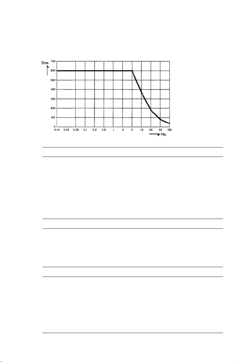
For derating of each input probe (red or black), see the figure below.
Input Characteri stics
Input probe tip style Shrouded banana probe tip
Probe cabl e length 1.5 meter (60 inches)
Maximum input voltage t o ground600V CAT III
1000V CAT II
Maximum differential input
voltage
1000 VDC, or
1000 Vrms, or
1200V (DC + AC pe ak)
Output Characteristics
Output Characteristics
Output ca ble Safety de signed BNC cable
Cable length 0.5 meter (20 inches)
Maximum output voltage range 6.5 V into 1 M
±Ω
Environmental Specifications
Temperature Operatin g: 0 °C to +50 °C ( +32 °F to +122 °F)
Storage: -10 °C to +60 °C (+ 14 °F to +140 °F)
Altitude Op erating: 3 km ( 9850 feet)
Storage : 12km (40,00 0 feet)
7

N2772A Differential Voltage Probe
Characteristics and Specifications
Meets requirements of: MIL-T-28800E, Type III, Class 3.
EN 50081-1 , Electromagne tic Compati bility Gener ic
Emission Standard: EN55022 and EN60555-2.
EN 50082-2 , Electromagne tic Compati bility Gener ic
Immunit y Standard: IEC801-2, -3, -4, -5. (see also
Tables 1 an d 2)
This produc t i s i n c onfor mit y wi th El ect ro magne tic
Compatib ility Dir ective 89 /336/EEC and Low Voltage
Directive 73/23/EEC.
This conformity is indi cated by the follo w ing
symbol, i.e. "Conformi té Européenne ".
The N2772A conforms with the EEC directive 89/336 for EMC immunity, as
defined by IEC801-3, with the addition of the following table.
Table 1
Susceptibility
(in % of full dynamic range)
Frequency range:
E = 3 V/m E = 10 V/m
10 kHz to 25 MHz
20x <1% <1%
200x <1% <1%
Frequency range:
E = 3 V/m E = 10 V/m
25 MHz to 1 GHz
20x <=1% <=2%
200x <=1% <=2%
Safety Specifications
Meets requirements of: EN61010-2-31 (IEC1010-2-31)
Complia n t w ith: UL3111-1 (including listing)
CSA C222. 2 No. 1010.1-92 (approval: pending)
Max float ing output voltage 600V Category III, up to 400Hz. (From shielding to
ground.)
8
N2772A Differential Voltage Probe
Characteristics and Specifications
WARNING SHOCK HAZARD!
These probes are designed for use with oscilloscopes that have a common
!
WARNING Do the following to avoid electrical shock or fire if the probe is connected to
terminal at GROUND POTENTIAL (in accordance with OSHA requirements and
the National Electric Code). Exposed metallic surfaces of the probe and the
oscilloscope MUST BE GROUNDED. Failure to ground the common terminal
during certain applications, such as those requiring the oscilloscope to be
powered from an external battery, might expose the operator to an electrical
shock hazard that could be lethal (depending on voltage and current conditions.)
more than 42V peak (30V rms):
• Use only the N2773A power adapter or a 9V battery.
• Connect the power adapter to the AC outlet before connecting it to the
N2772A.
• Do not insert metal objects in the power adapter connector.
• Use 600V rated test lead adapters. The maximum allowable input
voltage is 600V, Category III.
This symbol signifies that the N2772A Differential Probe is protected by
double or reinforced insulation. Only use specified replacement parts
when servicing the instrument.
This symbol signifies CAUTION! and requests that the user refer to the
user manual before using the instrument.
!
9

N2772A Differential Voltage Probe
Using the N2772A Probe
Using the N2772A Probe
Powering the N2772A
The N2772 probe can be powered either by an internal 9V battery or the N2773A
power supply. The battery has a limited life. For this reason the probe has a LOW
BATTERY indicator and will automatically switch to STAND BY mode after
approximately 30 minutes. If you store the probe for extended periods of time,
remove the battery and store it separately.
External Power Supply
For convenience the N2773A power supply is recommended. When you use this
power supply, take care to select the appropriate voltage with the switch on the
rear of the probe power supply. The power source has been designed to provide
the correct power with 50 Hz, 60 Hz and 400 Hz sources of 115V and 230V.
10

N2772A Differential Voltage Probe
Using the N2772A Probe
Install or Replace the Battery
WARNING Never install or replace the battery while the probe is connected to a voltage
source. Replace the battery when the red LED is lit, or when both red and green
!
LED’s are off when the probe is switched on.
The expected battery life is 8 hours of operation and 400 hours in auto standby.
Oscilloscope Input Characteristic
The probe has been designed to drive a 1M input to maximize battery life. The
input capacitance of the oscilloscope should be < 50 pF.
Ω
11

N2772A Differential Voltage Probe
Using the N2772A Probe
Select the Correct Attenuation on the Probe and the Oscilloscope
The probe has two modes of operation, 20:1 and 200:1 attenuation. Select the
desired attenuation on the probe and the correct probe attenuation setting on
the oscilloscope. This will ensure that accurate voltage readings can be made
directly from the oscilloscope.
Measurement Tips
• Use the 20x range on the differential voltage probe for smaller signals,
such as ripple on a high voltage reference lead.
• When the probe is battery operated, the red LED indicates that the
battery level is low and the battery needs to be replaced.
• When battery operated, the probe automatically goes to standby mode
after 30 minutes to conserve battery power. A blinking green LED
indicates that the probe is in standby mode. To continue operation, turn
the range selection switch from OFF to 20x or 200x.
• Connect the red probe cable to a more positive or more negative voltage
level than the black probe cable.
12

N2772A Differential Voltage Probe
Calibration
Calibration
To guarantee that your instrument complies with the factory specifications, we
recommend that you submit the differential probe to your local Agilent
Technologies Service Center at one year intervals for recalibration, or as required
by other standards.
Cleaning the Probe
Disconnect the probe from all power sources and clean it with a soft cloth
dampened with a mild soap and water solution. Be careful not to get water in the
attenuation switch. Make sure the probe is completely dry before reconnecting
it to a power source.
13

14

DECLARATION OF CONFORMITY
according to ISO/IEC Guide 22 and EN 45014
Manufacturer’s Name: Agilent Technologies Company
Manufacturer’s Address: Colorad o Springs Divisi on
1900 Garden of the Gods Road
Colorado Springs, CO 80907, U.S.A.
declares, that the product
Product Name: Differential Voltage Probe
Model Number(s): N2772A
Product Option(s): All
conforms to the following Product Specifications:
Safety: IEC 1010-1:1990+A1 / EN 61010-1:1993
UL 3111
CSA-C22.2 N o. 1010.1:1993
EMC: CISPR 11:1990 / EN 55011:1991 Group 1, Class A
IEC 555-2:1982 + A1:1985 / EN60555-2:1987
IEC 555-3:1982 + A1:1990 / EN 60555-2:1987 + A1:1991
IEC 801-2:1991 / EN 50082-1:1992 4 kV CD, 8 kV AD
IEC 801-3:1984 / EN 50082-1:1992 3 V/m, {1kHz 80% AM, 27-1000 MHz}
IEC 801-4:1988 / EN 50082-1:1992 0.5 kV Sig. Lines , 1 kV Power Lines
Supplementary Information:
The product herewith complies with the requirements of the Low Volta ge Directive 73/23/EEC
and the EMC Dir ective 89/336/EEC, and carries the CE-marking accordingly.
This pro duct was tested i n a typical configuration with Agilent Technologies test systems.
Colorad o Springs, 11/12/1999
Ken Wyatt, Quality Manager
European Contact: Your local Agilent Technologies Sales and Service Office or Agilent Technologies GmbH,
Department ZQ/ Standar ds Europe, Herre nber ger Stra sse 130, D-71034 Böblin gen German y (FAX: +49-70 31-14-31 43)


© Copyright
Agilent Technologies 1999-
2000.
All Rights Reserved.
Reproduction, ad aptation,
or translation without prior
written permission is
prohib ited, except as
allowed under the copyright
laws.
Restric ted Rights
Legend.
Use, duplication or
disclo sure by the U.S .
Government is subject to
restrictions as set forth in
subparagraph (c) (1) (ii) of
the Rights in Technical Data
and Computer Software
clause at DFARS 252.2277013 for DOD agencies, and
subparagraphs (c) (1) and
(c) (2) of the Commercial
Computer Software
Restricted Rights clause at
FAR 52.227-19 for other
agencies.
Agilen t Technologies
3000 Hanover Street
Palo Alto, California 94304
U.S.A.
Document Warranty
The information contained
in this document is subject
to change without notice.
Agilent makes no
warranty of any kind
with regard to this
material, including, but
not limited to, the
implied warranties of
merchantability or
fitness for a particular
purpose.
Agilen t sha ll not be liabl e
for errors contained herein
or for damages in
connection with the
furnishing, perfo rmance, or
use of this mate rial.
Product Warranty
This Agilent product has a
warranty against defects in
material and workmanship
for a period of one year
from date o f shipment.
During the warranty period,
Agilent Technologies will, at
its option, either repair or
replace products that prove
to be defective.
For warranty service or
repair, this product must be
returned to a service facility
designated by Agilen t.
For products retur ned to
Agilent for warranty
service, the Buyer shall
prepay shipping charges to
Agilent and Agilent shall
pay shipping charges to
return the product to the
Buyer. However, the Buyer
shall pay all shipping
charges, duties, and taxes
for products returned to
Agilent from another
country.
Agilent warrants that its
software and firmware
designated by Agilen t for
use with an instrument will
execute its programming
instructions when properly
installed on that
instrument. Agilent does
not warrant that the
operation of the instrument
software, or firmware will
be uninterru pted or erro r
free.
Limitation of Warranty
The for egoin g warranty
shall not apply to defects
resulting from improper or
inadequate maintenance by
the Buye r, Buyer-supplied
software or interfacing,
unauthorized modification
or misuse, operation outside
of the environ mental
specifications for the
product, or improper site
preparation or
maintenance.
No other warranty i s
expressed or implied.
Agilent specifically
disclaims the implied
warranties of
merchantability or
fitness for a particular
purpose.
Exclusive Remedies
The remedies provided
herein are the buyer's sole
and exclusive remedies.
Agilent shall not be liable
for any direct, indirect,
special, incidental, or
consequential damages,
whether based on contract,
tort, or any other legal
theory.
Assistance
Product maintenance
agreements and other
customer assistance
agreements are available for
Agilent products .
For any assistance, contact
your nearest Agilent Sales
Office.
Certification
Agilent Technologies
certifies that this product
met its published
specifications at the time of
shipment from the factory.
Agilent fur ther certifies that
its cal ibrat ion
measurements are traceable
to the United States
National Institute of
Standards and Technology,
to the extent allowed by the
Institute's calib ration
facility, and to the
calibration facilities of other
International S tandards
Organization m embers.
Agilen t Technologies
P.O. Box 2197
1900 Garden of the Gods Road
Colorado Springs, CO 80901

Safety
This apparatus has been
designed and tested in
accordance with IEC
Publication 1010, Safe ty
Requirements for
Measuring Apparat us, and
has been supplied in a safe
condition. To ensure safe
operation and to keep the
product safe, the
information, cautions, and
warnings in this operating
manual must be heeded. In
addition, note the external
markin gs on the instrument
that are described under
"Safet y Symbols."
Safety Symbols
!
Instruction manual symbol:
the product is marked with
this symbol when it is
necessary for you to refer to
the instruction manual in
order to protect against
damage to the product.
Hazardous voltage symbol.
Earth terminal symbol:
Used to indicate a circuit
common connected to
grounded chassis.
WARNING
The Warning sign denotes a
hazard . It calls at tention to
a procedure, practice, or
the like, which, if not
correctly performed or
adhered to, could result in
personal injury. Do not
proceed beyon d a Warning
sign until the indicated
conditions are fully
understood and met.
CAUTION
The Caution sign denotes a
hazard . It calls at tention to
an operating procedure,
practice, or the like, which,
if not correctly performe d
or adhered to, could result
in damage to or destruction
of part or all of the product.
Do not proceed beyond a
Caution symbol until the
indicated conditions are
fully understood or met.
About this edition
This is the N2772
Differential Voltage Probe
User’s Guide.
Publication number
N2772-92001, Mar. 2000
Printed in USA.
Print history is as follows:
N2772-92000, Nov. 1999
N2772-92001, Mar. 2000
New editions are complete
revisions of the manual.
Many product updates do
not require manual
changes; and, conversely,
manual corrections may be
done without accompanying
product changes.
Therefore, do n ot expect a
one-to-one correspondence
between product updates
and manual updates.


s1
Agilent Technologies
Printed in the USA
Manual Part Number
N2772-92001
$
 Loading...