

Page 1

IDP-15
Dry Scroll
Vacuum Pump
Vacuum Products Division
INSTRUCTION MANUAL
Manual No. X3815 90000
Revision B
August 2013
DRAFT 8/22/13
Page 2

IDP-15
Dry Scroll Vacuum Pump
DRAFT 8/22/13
Copyright 2013
Agilent, Inc.
Page 3

IDP-15 Dry Scroll Vacuum Pump
Warranty
Products manufactured by Seller are warranted against defects in materials and workmanship for twelve (12) months from
date of shipment thereof to Customer, and Seller's liability under valid warranty claims is limited, at the option of Seller, to
repair, to replace, or refund of an equitable portion of the purchase price of the Product. Items expendable in normal use
are not covered by this warranty. All warranty replacement or repair of parts shall be limited to equipment malfunctions
which, in the sole opinion of Seller, are due or traceable to defects in original materials or workmanship. All obligations of
Seller under this warranty shall cease in the event of abuse, accident, alteration, misuse, or neglect of the equipment.
In-warranty repaired or replaced parts are warranted only for the remaining unexpired portion of the original warranty
period applicable to the repaired or replaced parts. After expiration of the applicable warranty period, Customer shall be
charged at the then current prices for parts, labor, and transportation.
Reasonable care must be used to avoid hazards. Seller expressly disclaims responsibility for loss or damage caused by use
of its Products other than in accordance with proper operating procedures.
Except as stated herein, Seller makes no warranty, expressed or implied (either in fact or by operation of law), statutory or
otherwise; and, except as stated herein, Seller shall have no liability under any warranty, expressed or implied (either in
fact or by operation of law), statutory or otherwise. Statements made by any person, including representatives of Seller,
which are inconsistent or in conflict with the terms of this warranty shall not be binding upon Seller unless reduced to
writing and approved by an officer of Seller.
Warranty Replacement and Adjustment
All claims under warranty must be made promptly after occurrence of circumstances giving rise thereto, and must be
received within the applicable warranty period by Seller or its authorized representative. Such claims should include the
Product serial number, the date of shipment, and a full description of the circumstances giving rise to the claim. Before any
Products are returned for repair and/or adjustment, written authorization from Seller or its authorized representative for the
return and instructions as to how and where these Products should be returned must be obtained. Any Product returned to
Seller for examination shall be prepaid via the means of transportation indicated as acceptable by Seller. Seller reserves
the right to reject any warranty claim not promptly reported and any warranty claim on any item that has been altered or
has been returned by non-acceptable means of transportation. When any Product is returned for examination and inspection, or for any other reason, Customer shall be responsible for all damage resulting from improper packing or handling,
and for loss in transit, notwithstanding any defect or non-conformity in the Product. In all cases, Seller has the sole responsibility for determining the cause and nature of failure, and Seller's determination with regard thereto shall be final.
If it is found that Seller's Product has been returned without cause and is still serviceable, Customer will be notified and
the Product returned at the Customer's expense; in addition, a charge for testing and examination may be made on Products so returned.
T 8/22/13
DRAF
3
Page 4

IDP-15 Dry Scroll Vacuum Pump
DRAFT 8/22/13
This page intentionally left blank.
Page 5

IDP-15 Dry Scroll Vacuum Pump
Contents
Instructions for Use ........................................................................................................................... 7
General Information ..................................................................................................................... 7
Storage.................................................................................................................................... 8
Maintenance ................................................................................................................................. 8
Technical Information ......................................................................................................................... 9
Unpacking and Inspection........................................................................................................... 13
Preparation for Installation ....................................................................................................13
Installation................................................................................................................................... 14
Safety.................................................................................................................................... 14
Setting the Mains Voltage ..................................................................................................... 15
Startup................................................................................................................................... 15
Electrical Connections........................................................................................................... 16
Run Currents......................................................................................................................... 18
Start Current.......................................................................................................................... 18
Mechanical Connections ....................................................................................................... 19
Operation .................................................................................................................................... 20
Cleaning the Pump................................................................................................................ 20
IDP-15 Integrated Isolation Valve ...............................................................................................20
Troubleshooting .......................................................................................................................... 22
Maintenance ............................................................................................................................... 23
Cleaning................................................................................................................................ 23
Kits and Service Options....................................................................................................... 23
Tip Seal Replacement...........................................................................................................24
DRAFT 8/22/13
5
Page 6

IDP-15 Dry Scroll Vacuum Pump
22/13
DRAFT 8/
This page intentionally left blank.
Page 7

IDP-15 Dry Scroll Vacuum Pump
Instructions for Use
General Information
This equipment is designed for use by professionals. The user should read this
instruction manual and any other additional information supplied by Agilent before
operating the equipment. Agilent will not be held responsible for any events that occur
due to non-compliance with these instructions, improper use by untrained persons,
non-authorized interference with the equipment, or any action contrary to that provided
for by specific national standards.
The IDP-15 is a hermetic, dry scroll vacuum pump. This pump is suitable for pumping air
or inert gases. The pump is not intended to pump corrosive, explosive, or
particulate-forming gases.
The following paragraphs contain all the information necessary to guarantee the safety of
the operator when using the equipment. Detailed information is supplied in “Technical
Information” on page 10.
This manual uses the following standard safety protocol:
/22/13
DRAFT 8
WARNING The warning messages are for attracting the attention of the
operator to a particular procedure or practice which, if not
followed correctly, could lead to serious injury.
CAUTION The caution messages are displayed before procedures,
which if not followed, could cause damage to the equipment.
NOTE The notes contain important information taken from the text.
8
Page 8

Storage
IDP-15 Dry Scroll Vacuum Pump
When transporting and storing the pump, the following environmental requirements
should not be exceeded:
Temperature: 20 °C to +60 °C (4 °F to 140 °F)
Relative humidity: 0 to 95% (non-condensing)
Maintenance
Personnel responsible for pump operation and maintenance must be well-trained and
aware of the accident prevention rules.
Atmospheric
500 to 1060 hPa
pressure:
WARNING ❑ Death may result from contact with high voltages. Always take
extreme care and observe the accident prevention regulations in
force.
❑ When machine is powered up, be careful of moving parts and high
voltages.
❑ If you have to perform maintenance on the pump after a considerable
time in operation, allow it to cool as the temperature of the interior
metal parts can be in excess of 60 °C.
❑ Always disconnect your power supply to the pump before beginning
maintenance work.
NOTE Before returning the pump to the factory for repair, the “Health
and Safety” sheet attached to this instruction manual must be
completed and sent to the local sales office. A copy of the
sheet must be inserted in the pump package before shipping.
DRAFT 8/22/13
If a pump is to be discarded, it must be disposed of in accordance with specific national
standards.
9
Page 9

IDP-15 Dry Scroll Vacuum Pump
Technical Information
Table 1 Specifications
Model IDP-15 Dry Scroll Single Hermetic Vacuum Pump
Interface dimensions See Figure 1 on page 12
Peak pumping speed
Media No corrosive, explosive or particulate forming gases
Ultimate pressure 10 x 10
Maximum inlet pressure 1.0 atmosphere (0 psig)
Maximum outlet pressure 6.5 psig
Inlet connection NW25
❑ 50 Hz: 257 L/m, 15.4 m
❑ 60 Hz: 213 L/m, 12.8 m
3
Torr (13.3 x 10³ mbar)
3
3
/hr
/hr
Exhaust connection NW16
Gas ballast 1/4" NPTF (two positions)
/22/13
Ambient operating temperature 5 °C to 40 °C (41 °F to 104 °F)
Storage temperature –20 °C to 60 °C (–4 °F to 140 °F)
Motor rating 0.75 HP (560 W)
Operating voltages
DRAFT 8
Run current See Table 5 on page 19
Motor thermal protection Automatic thermal protection
Operating speed 60 Hz: 1725 RPM, 50 Hz: 1450 RPM
Cooling system Air-cooled
Weight Pump only: 34 kg (75 lbs)
Leak rate (with exhaust and gas
ballast sealed)
Vibration level at inlet, per ISO
10816-1
Water vapor handling per PNCUROP 6602:
❑ Position 1: 20.7 g/hr
❑ Position 2: 235 g/hr
❑ 1 phase/ 100 (± 10%) VAC, 50/60 Hz
❑ 1 phase/ 115 (± 10%) VAC, 60 Hz
❑ 1 phase/ 220-230 (± 10%) VAC, 50/60 Hz
Shipping weight: 45 kg (100 lbs)
6
<1 x 10
9 mms
sccs helium
-1
rms
10
Page 10

IDP-15 Dry Scroll Vacuum Pump
Table 1 Specifications (Continued)
Noise level, per ISO 11201 50 dBA ± 2dBA
Fuse type Littelfuse, Series 215, 10 A, 250 V, 20 mm L x 5.2 mm D,
Time Delay / Slow Blow or equivalent, vendor part number 0215010
P.
Pollution Degree 2
Installation Category II
Altitude 2000 m
Humidity 0- 95% (non-condensing)
Indoor use only
11
DRAFT 8/22/13
Page 11
IDP-15 Dry Scroll Vacuum Pump
/22/13
DRAFT 8
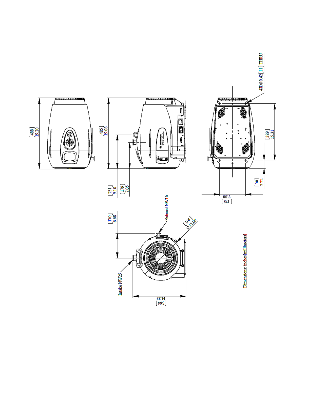
Figure 1 Interface Drawing with Dimensions
12
Page 12

IDP-15 Dry Scroll Vacuum Pump
8
9
10
111213
14
➀ Front Cowling Screws; M5 (6)
➁ Front Cowling
➂ Inlet (NW25)
➃ Inlet Screen
➄ Exhaust NW16
➅ Gas Ballast Port 1 (1/4" NPT filter plug,
provided)
➆ Gas Ballast Port 2 (1/4" NPT filter plug,
provided)
Mounting Holes
Rear Cowling Screws: M5 (2)
On/Off Switch/Power Connection
(IEC-320) and Fuse Holder
Hour Meter
Figure 2 Outline Drawing and Principal Items
Voltage Selector Switch
Access holes: shipping locks
Rear cowling
DRAFT 8/22/13
13
Page 13

IDP-15 Dry Scroll Vacuum Pump
Unpacking and Inspection
Preparation for Installation
The pump is supplied in a special protective packing. If this shows signs of damage,
which may have occurred during transport, contact your local sales office.
Total weight of the packing, IDP-15 pump included, is approximately 45.5 kg (100 lbs).
WARNING When unpacking the pump, be sure not to drop it and avoid
any kind of sudden impact or shock vibration to it.
NOTE Normal exposure to the environment cannot damage the
pump. Nevertheless, it is advisable to keep the pump inlet
closed until the pump is installed in the system.
/22/13
1. Orient the shipping container with This End Up on top.
2. Open the box, remove the foam block and carefully lift the IDP-15 out of the box.
Remove the plywood base.
3. Save the carton and all packing materials.
4. Inspect the pump for damage. If there is shipping damage, contact the freight carrier
DRAFT 8
and your local Agilent sales office immediately.
5. Loosen the two front and two rear cowling screws and slide the L-brackets up.
Retighten the cowling screws. The pump now rests on its rubber feet.
6. Disengage shipping locks and enable vibration isolation by inserting a 4 mm Allen
wrench into each of the four shipping lock access holes (Figure 2 on page 13) and
turning the screws clockwise until significant resistance occurs. The pump body is
now floating on its isolation mounts.
CAUTION Before operating the IDP-15 disengage the shipping locks
(Figure 2 on page 13).
CAUTION Engage the shipping locks (Figure 2 on page 13) when
shipping, moving a long distance or during long-term storage.
14
Page 14

Installation
There are two versions of the IDP-15:
❑ Fixed speed: 100-115/200-230 VAC, 50/60 Hz
❑ Inverter drive: 100-115/200-230 VAC, 50/60 Hz, user-settable drive frequency,
During operation, the following environmental conditions must be respected:
Safety
IDP-15 Dry Scroll Vacuum Pump
40-75 Hz
Temperature: +5 °C to +40 °C (41 °F to 104 °F)
Relative humidity: 0 to 95% (non-condensing)
WARNING Do not remove or modify any safety or insulating equipment
from the pump. To do so may create a serious safety hazard
and may void the warranty.
WARNING The pump is designed for operation with neutral or
noncorrosive gases. Do not use it with potentially explosive or
inflammable substances.
WARNING ❑ This pump is capable of pumping air and inert gases only. It is not
designed to pump explosive, flammable, corrosive or particulate
forming gases. They can cause bodily injury, explosion, or fire.
❑ Install in an area that is not exposed to rain, steam, or excessive
humidity. They can cause electric shock, short circuits, and severe
bodily injury.
❑ Before inspecting or servicing the pump, be sure the electrical supply
is disconnected.
❑ The gas ballast must be sealed whenever pumping any gas not
intended to be vented to the atmosphere
CAUTION ❑ Although the pump can pump trace particulates normally found in the
atmosphere, it is not designed to process solids, chemicals, powders,
solvents, condensates, or other particulates. They can damage the
equipment, degrade its performance, or shorten its useful life.
❑ Do not install or use the pump in an environment exposed to
atmospheric agents (rain, snow, ice), dust, aggressive gases, or in
explosive environments or those with a high fire risk.
❑ If placing the IDP-15 pump inside an enclosure, provide ample room
to supply ambient air to both the front and rear air intakes of the
pump.
DRAFT 8/22/13
15
Page 15

CAUTION Engage the shipping locks (Figure 2 on page 13) when
CAUTION ❑ Be certain that your electrical mains power voltage corresponds to
Setting the Mains Voltage
To set the mains voltage:
❑ Slide the voltage selector switch to 115 for 115-120 V mains, or to 230 for 200-230
V mains.
Startup
IDP-15 Dry Scroll Vacuum Pump
shipping, moving a long distance or during long-term storage.
that indicated on the fuse/voltage switch.
❑ Connect the pump to the power supply using an IEC-320 style power
cord of at least 10 A capacity.
In order to reach maximum vacuum, the pump must be left running for about an hour with
the inlet sealed.
/22/13
There are no special instructions for starting the pump; it need only be switched on using
the On/Off switch.
1. Check that the inlet screen is installed before beginning operation.
DRAFT 8
2. Operate the pump at an ambient temperature of 5 °C to 40 °C (41 °F to 104 °F),
otherwise damage to the pump or shortened operating life may result.
WARNING Do not insert a finger or any foreign object in the path of the
fan; serious personal injury may result or the pump may be
damaged.
CAUTION Do not block the fan ducts. Blocking these ducts can cause
pump overheating. A pump surface temperature in excess of
65 °C (150 °F) is potentially damaging. If such conditions are
observed, turn the pump off and allow it to cool. Disassemble,
inspect for damage, and repair, if necessary.
16
Page 16

Electrical Connections
For 100/115 V service, connect the IDP-15 to a 15 A circuit. Operation in a smaller
capacity circuit can cause nuisance circuit breaker trips when the motor is started,
especially if mains voltage is below 100 V.
When incorporating the IDP-15 into other equipment, only use circuit breakers rated for
the motor start service. Use of circuit breakers smaller than 15 A or that are not rated for
motor starting can result in nuisance trips.
Power Cord
Several power cord options are available from your Agilent dealer. Descriptions of the
available power cords and their ordering numbers are given in Table 3.
NOTE For high voltage operation, the pump must be connected to
IDP-15 Dry Scroll Vacuum Pump
the power supply using a high voltage IEC-320 type power
shielded cord of at least 10 A rated capacity.
CAUTION Be certain that your electrical mains power voltage
corresponds to that indicated on the rear of the pump.
Table 3 IDP-15 Power Cord Selection
Country Power Cord Specification Order
Europe 10 A / 220-230 VAC, 2.5 m 656494220
Denmark 10 A / 220-230 VAC, 2.5 m 656494225
Switzerland 10 A / 230 VAC, 2.5 m 656494235
UK/Ireland 13 A / 230 VAC, 2.5 m 656494250
India 10 A / 220-250 VAC, 2.5 m 656494245
Israel 10 A / 230 VAC, 2.5 m 656494230
Japan 12 A / 100 VAC, 2.3 m 656494240
15 A / 125 VAC, 2.0 m 656458203
North America
10 A / 230 VAC, 2.5 m 656494255
DRAFT 8/22/13
17
Page 17

Grounding Instructions
Grounding Pin
Grounded
Outlet
Grounded
Outlet
Box
This product should be grounded. In the event of an electrical short circuit, grounding
reduces the risk of electric shock by providing an escape wire for the electric current. This
pump must be equipped with a power cord that has a grounding wire with an appropriate
grounding plug. The plug must be inserted into an outlet that is properly installed and
grounded in accordance with all local codes and ordinances.
WARNING Improper installation of the grounding plug can result in a risk
IDP-15 Dry Scroll Vacuum Pump
of electrical shock. For United States and Canadian
installations:
❑ When this product is configured for use on a nominal 120 V circuit, it
must be used with a grounding plug that looks like the plug illustrated
in Figure 4.
❑ If repair or replacement of the cord or plug is necessary, connect
the grounding wire to the grounding terminal only.
❑ The grounding wire is insulated and its outer surface is green. It may
or may not have yellow stripes.
❑ When this product is configured for use on a nominal 220 V circuit, it
must be used with a factory supplied cord and plug that permits
connection to the proper electric circuit. See “Electrical Connections”
on page 17 for proper rating and type of cord set.
/22/13
DRAFT 8
WARNING ❑ Check with a qualified electrician or serviceman if the grounding
instructions are not completely understood, or if you are in doubt as to
whether the product is properly grounded.
❑ Do not modify the plug provided; if it does not fit the outlet, have the
proper outlet installed by a qualified electrician.
❑ Connect the product only to an outlet that has the same configuration
as the plug. Do not use an adapter with this product.
Figure 4 Grounding Plug and Outlet
WARNING If the product must be reconnected for use on a different type
of electric circuit, the connector should be replaced by
qualified service personnel.
Extension Cords
Do not use extension cords.
18
Page 18

IDP-15 Dry Scroll Vacuum Pump
Run Currents
Typical run currents listed in Table 5 are with pump blanked off.
Table 5 IDP-15 Typical Run Currents (A)
Frequency 100 V Nominal 115 V Nominal 220 V Nominal 230 V Nominal
90 V 100 V 110 V 103.5 V 115 V 127 V 198 V 220 V 230 V 253 V
60 Hz
50 Hz
Start Current
Table 6 lists the typical IDP-15 maximum starting current and duration.
4.23 4.06 4.02 4.03 4.06 4.74 2.87 2.77 2.64 2.51
4.20 4.50 6.13 N/A N/A N/A 1.93 2.42 2.81 4.02
Table 6 Typical IDP-15 Maximum Starting Current and Duration
50 Hz 60 Hz
Mains
Voltage
100 V 22.6 < 1 sec. 23.5 < 1 sec.
115 V N/A N/A 21.2 < 1 sec.
220 V 11.9 < 1 sec. 14.2 < 1 sec.
230 V 11.7 < 1 sec. 13.9 < 1 sec.
Current (A) Time (ms) Current (A) Time (ms)
DRAFT 8/22/13
19
Page 19

Mechanical Connections
Pump Inlet
Use NW25, or larger, clean vacuum hardware with as short a length as practical between
the pump and vacuum chamber.
Insert a bellows between the pump and vacuum chamber to provide both vibration
isolation and strain relief.
Pump Exhaust
An NW16 exhaust fitting is located on the side of the pump. To avoid overheating the
pump, do not restrict the exhaust flow with long lengths of small diameter tubing. Use as
short as practical lengths of 16 mm ID, or larger, diameter hardware.
Gas Ballast
When pumping gas loads containing water vapor or condensable gases, use the gas
ballast. To activate gas ballast, remove the solid 1/4 NPT plug from either port 1 or port 2,
and install the sintered filter plug provided with the pump (see Figure 2 on page 13).
IDP-15 Dry Scroll Vacuum Pump
/22/13
Gas ballast port 1 is used for moderate water vapor loads (up to 20.7 g/hr), such as
intermittently pumping out a volume exposed to normal ambient humidity. Gas ballast port
2 is used for high water vapor loads (up to 235 g/hr), such as repetitively pumping out a
volume exposed to excessive ambient humidity, or process gas loads with a high water
DRAFT 8
vapor content.
For applications where ingress of air is undesirable, dry nitrogen at a flow rate of
approximately 5 l/min can be provided to the gas ballast inlet by making a 1/4 NPT
connection to the port.
CAUTION If hazardous materials are pumped, do not use gas ballast.
CAUTION Pumping high water vapor loads can cause a temporary
increase in ultimate pressure, due to adsorption and
absorption of water vapor by the internal surfaces of the
pump. Pumping water vapor loads in excess of the water
vapor handling capability of the gas ballast can cause
reduced time between tip seal replacements.
20
Page 20

IDP-15 Dry Scroll Vacuum Pump
Operation
Cleaning the Pump
Unlike conventional oil-sealed pumps, Agilent dry scroll pumps do not contain fluid for the
cleansing of accumulated dust and debris. Run the pump periodically with the inlet open
to atmosphere for a minute or two to flush it out. Until experience is gained on your
specific process, flush the pump regularly and adjust this schedule according to your
specific conditions.
IDP-15 Integrated Isolation Valve
The IDP-15 scroll pump offers an optional, factory-installed Integrated Isolation Valve built
into pump module. This option is installed into the body of the pump and does not affect
the external size of the pump or the height of the inlet flange.
All IDP-15 scroll pumps are supplied with an exhaust valve to prevent rapid leak-up to
atmospheric pressure. However, any vacuum pump generates a small increase in inlet
line pressure when turned off. This can cause a small amount of pump debris to be
carried back into the vacuum line or chamber when pump power is interrupted. For
applications where the process is sensitive to contamination from pump debris, install a
fast acting, automatic, normally closed valve at the pump inlet to prevent pump debris
from migrating backwards through the pump inlet.
The Integrated Isolation Valve is a safety valve that protects the vacuum system in the
event of power failure by isolating the vacuum system from the vacuum pump and venting
the pump to atmospheric pressure. The Integrated Isolation Valve is designed to prevent
any tip seal debris back streaming into the vacuum system. The valve operates with
atmospheric pressure and activates upon loss of electrical power. The lifetime is in
excess of 200,000 cycles, which translates into years of trouble free use in suitable
environments. The opening burst pressure, approximately 5 x-10
than the critical backing pressure for turbo molecular and diffusion pumps.
The Integrated Isolation Valve's solenoid valve is connected in parallel with the IDP-15
electrical supply. When the electrical power is on, the solenoid valve is closed, which
allows the pump to keep the Integrated Isolation Valve's body and the vacuum system
evacuated. Interruption of electrical power to the pump causes the solenoid valve to
open. Air is admitted into the Integrated Isolation Valve causing it to close very quickly.
This isolates the vacuum system from the pump, while the pressure differential between
the outside atmosphere (inside the pump) and the vacuum system provides the force
necessary to maintain the valve in its closed position without electric or pneumatic power.
-2
Torr, is typically less
DRAFT 8/22/13
21
Page 21

IDP-15 Dry Scroll Vacuum Pump
With the vacuum system isolated, a very small orifice admits air from the inside the pump
to the lower chamber of the Integrated Isolation Valve until its pressure has risen to
atmospheric pressure. When the pump is restarted, it starts to evacuate the valve's lower
chamber volume first until the pressure is lowered to approximately that of the vacuum
system. At that moment the spring activated diaphragm automatically opens again (with a
10 sec delay to avoid back burst in the vacuum system) allowing the vacuum system to
be pumped at the full speed of the pump.
/22/13
DRAFT 8
22
Page 22

IDP-15 Dry Scroll Vacuum Pump
Troubleshooting
Use the Troubleshooting chart in Table 7 to assist in defining a problem, determining a
possible cause, and defining action steps to remedy the situation.
Table 7 Troubleshooting Chart
Problem Possible Causes Corrective Actions
Will not start Motor thermal protector
open
Blown fuse Replace fuse.
Excessive voltage drop Check size and length of cable.
Defective motor Inspect. Contact Agilent.
Poor ultimate
pressure
Hammering
noise
System leak Locate and repair leak.
Water in pump Flush pump with air or dry nitrogen.
Solvent in pump Flush pump with air or dry nitrogen.
Seals worn out Replace tip seals.
Poor conductance to pump Replumb with shorter and/or larger diameter tubing.
Integrated Isolation Valve
(option) solenoid failure
Pump overheated Check ventilation to pump.
Debris in pump Check intake screen.
Allow motor to cool.
Identify cause of overload.
Install trap or filter.
Contact Agilent.
Check ambient temperature.
DRAFT 8/22/13
Flush pump.
Disassemble pump and inspect.
Pump runs
intermittently
The IDP-15 is equipped with an auto-reset thermal motor protector. This protector automatically
*
shuts down the pump when it detects an overload condition, and automatically restarts the pump
when the motor has cooled to within an acceptable temperature range.
Motor thermal protector is
cycling open and closed.*
Allow the motor to cool.
Identify the cause of the overload.
23
Page 23

Maintenance
Cleaning
Exterior
The exterior surfaces of the IDP-15 may be cleaned with alcohol or mild detergents only.
Interior
Run the pump periodically with the inlet open at atmosphere for a minute or two to flush it
out. For more information, see “Cleaning the Pump” on page 21.
Kits and Service Options
Agilent pumps will provide many years of trouble-free service if the maintenance
procedures and intervals are observed. Cleaning and tip seal replacement are
recommended when pump base pressure has risen to an unacceptably high level for your
application. If your pump exhibits humming or grinding noises from the bearings, a major
overhaul should be done by Agilent personnel or an authorized rebuild center. Advance
exchange pumps are available to minimize downtime.
IDP-15 Dry Scroll Vacuum Pump
/22/13
The parts needed for tip seal replacement on the IDP-15 are available in the kit described
in Table 8. This kit contains seals and O-rings, and can be obtained from your Agilent
dealer.
DRAFT 8
Table 8 Tip Seal Replacement Kit
Part
Number Description Contents
X3815-67000 Replacement
Tip Seal Set
Replacement Tip Seal and
O-ring and grease for
IDP-15 pumps
24
Page 24

Tip Seal Replacement
Required Equipment
IDP-15 Dry Scroll Vacuum Pump
❑ Tip Seal Replacement Kit: P/N
X3815-67000
❑ Pry tool (screwdriver or something with
a flat edge the size of the tip seal)
❑ Lint-free wipes
IDP-15 Disassembly
❑ 4 mm and 5 mm Allen wrenches
❑ Isopropyl alcohol
WARNING If dangerous gases were being pumped, ensure the pump is
clear of all dangerous materials prior to disassembly.
Remove the Front Fan Cowling
1.Disconnect the power cord.
2. Remove the two screws holding the
bottom bracket using an 4 mm Allen key.
3. Support the cowling from the bottom with
one hand.
4. Loosen the four captive screws (two on left
side not shown) holding the cowling.
DRAFT 8/22/13
25
Page 25

IDP-15 Dry Scroll Vacuum Pump
IDP-15 Disassembly (Continued)
5. Rotate the cowl so that it clears the
exhaust port (red arrow).
6.Remove the cowling and lay it on its back.
7.Disconnect the white plug (red arrow). This
is an integral lock connector and is keyed to
plug together only one way.
/22/13
DRAFT 8
8.Remove the cowling to the side.
9.Remove the L-bracket and place to the side.
10.Lift the top console (red arrow) from the
front and rotate to one side.
26
Page 26

IDP-15 Dry Scroll Vacuum Pump
IDP-15 Disassembly (Continued)
Remove the Outboard Housing and
Remove Tip Seals
1.Use an 5 mm Allen key to remove the six
screws on the outboard housing (the three
screws on left not shown).
Remove the lower screws first to support the
housing.
2.Remove the housing and place to the side.
3.Remove the O-ring and discard.
4.Using a pry tool, remove the old tip seals.
There are a long and short tip seal on both the
orbiting plate and the outboard housing.
5.Clean all debris from the orbiting plate,
outboard housing and O-ring groove. Use
alcohol along with cotton swabs and wipes.
DRAFT 8/22/13
27
Page 27

IDP-15 Dry Scroll Vacuum Pump
IDP-15 Disassembly (Continued)
Tip Seal Replacement
1.Remove the new tip seal from the kit.The tip
seal is supplied in one length, sufficient to
create a short and a long segment for the
orbiting plate and the outboard housing (four
segments total).The tip seal cross section is
rectangular.The width is less than the height.
2.Install each tip seal segment, starting at the
inside so the 1/8” gap occurs at the end. Use a
flat wooden or plastic tool to press each
segment into its lock (red arrow). Each
segment has a lock (four total). Clean away
any tip seal debris generated when pressed
into each lock.
3.Cut each tip seal segment to a length that
leaves an 1/8” gap at the end.
/22/13
DRAFT 8
4.Lightly lubricate the O-ring with a trace of
vacuum grease. Use the Krytox 224 grease
supplied with the kit. Krytox LVP or Apezion L
can be substituted. Do not use vacuum grease
containing silicone.
28
Page 28

IDP-15 Reassembly
IDP-15 Dry Scroll Vacuum Pump
1. Align the outboard housing with the
orbiting plate using the pin and pin
alignment hole shown by the red arrows.
Ensure that the tip seals and O-ring do not
get pinched or misaligned.
2. Reinstall the six screws and tighten.
3. Reinstall the console by swinging it back
and aligning it with the body slots as
shown.
4. Place the bracket against the electrical tray
and align the bracket slots with the tapped
holes in the tray.
5. Plug the red/black fan connector together.
6. Align fan cowling by wiggling it over the
exhaust port. Replace and tighten the four
fan cowling screws.
7. Replace the two screws at the bottom of
the fan cowling. Lift and hold the bracket
while tightening these screws.
8. Reinstall the power cord.
To test the pump:
1. Run the pump for about 5 seconds. Verify that the front fan is running.
If you hear loud noises or observe labored operation, this indicates that the tip seal or main
O-ring are possibly out of place.
2. Disassemble and repair as necessary.
DRAFT 8/22/13
29
Page 29

IDP-15 Dry Scroll Vacuum Pump
The pump is now ready to return to service.
NOTE Newly installed tip seals may require several hours of run time
to seat properly and enable the pump to meet speed and
base pressure specifications.
/22/13
DRAFT 8
30
Page 30

IDP-15 Dry Scroll Vacuum Pump
Pg 1/3
NORTH AMERICA:
Fax: 1 781 860 9252
Toll Free: 800 882 7426, Option 3
PACIFIC RIM:
please visit our website for individual
office information
http://www.DJLOHQW.com
EUROPE:
Fax: 00 39 011 9979 330
Fax Free: 00 800 345 345 00
Toll Free: 00 800 234 234 00
Vacuum Products Division
Instructions for returning products
Dear Customer:
Please follow these instructions whenever one of our products needs to be returned.
1) Complete the attached Request for Return form and send it to Agilent Technologies (see below), taking particular care to identify
all products that have pumped or been exposed to any toxic or hazardous materials.
2) After evaluating the information, Agilent Technologies will provide you with a Return Authorization (RA) number via email or fax,
as requested.
Note: Depending on the type of return, a Purchase Order may be required at the time the Request for Return is submitted. We
will quote any necessary services (evaluation, repair, special cleaning, eg).
3) Important steps for the shipment of returning product:
x Remove all accessories from the core product (e.g. inlet screens, vent valves).
x Prior to shipment, drain any oils or other liquids, purge or flush all gasses, and wipe off any excess residue.
x If ordering an Advance Exchange product, pplease use the p
ackaging from the Advance Exchange to return the defective
product.
x Seal the product in a plastic bag, and package product carefully to avoid damage in transit. You are responsible for loss or
damage in transit.
x Agilent Technologies is not responsible for returning customer provided packaging or containers.
x Clearly label package with RA number. Using the shipping label provided will ensure the proper address and RA number
are on the package. Packages shipped to Agilent without a RA clearly written on the outside cannot be accepted and will
be returned.
4) Return only products for which the RA was issued.
5) PProduct being returned under a RA must be rece
ived within 15 business days.
6) SShip to the location specified on the printable label, which will be s
ent, along with the RA number, as soon as we have received
all of the required information. Customer is responsible for freight charges on returning product.
7) Return shipments must comply with all applicable SShippi
ng Regulations (IATA, DOT, etc.) and carrier requirements.
RETURN THE COMPLETED RREQUEST FOR RETURN FORM TO YOUR NEAREST LOCATION:
uest for Return Health and
Safety Certification
Req
This page intentionally left blank.
vpt-customercare@agilent.com
vpl-ra@agilent.com
Page 31

IDP-15 Dry Scroll Vacuum Pump
Pg 2/3
Vacuum Products Division
Request for Return Form
(Health and Safety Certification)
Please read important policy information on Page 3 that applies to all returns.
1) CUSTOMER INFORMATION
2) PRODUCT IDENTIFICATION
3) TYPE OF RETURN (Choose one from each row
and supply Purchase Order if requesting a billable service)
3A. Non-Billable Billable New PO # (hard copy must be submitted with this form):
3B. Exchange Repair Upgrade Consignment/Demo Calibration Evaluation Return for Credit
4) HEALTH and SAFETY CERTIFICATION
AGILENT TECHNOLOGIES CANNOT ACCEPT ANY PRODUCTS CONTAMINATED WITH BIOLOGICAL OR EXPLOSIVE HAZARDS,
RADIOACTIVE MATERIAL, OR MERCURY AT ITS FACILITY.
Call Agilent Technologies to discuss alternatives if this requirement presents a problem.
The equipment listed above (check one):
HAS NOT pumped or been exposed to any toxic or hazardous materials. OR
HAS pumped or been exposed to the following toxic or hazardous materials. If this box is checked, the following
information must also be filled out. Check boxes for all materials to which product(s) pumped or was exposed:
Toxic Corrosive Reactive Flammable Explosive Biological Radioactive
List all toxic/hazardous materials. Include product name, chemical name, and chemical symbol or formula:
________________________________________________________________________________________________________
NOTE: If a product is received at Agilent which is contaminated with a toxic or hazardous material that was not disclosed, the customer will be held responsible for all
costs incurred to ensure the safe handling of the product, and is liable for any harm or injury to Agilent employees as well as to any third party occurring as a result of
exposure to toxic or hazardous materials present in the product.
Print Name: Authorized Signature: ………………………. Date:
5) FAILURE INFORMATION:
I understand and agree to the terms of Section 6, Page 3/3.
Print Name: Authorized Signature: ………………………. Date:
Company Name: Contact Name:
Tel:
Customer Ship To:
Email:
Fax:
Customer Bill To:
Europe only: VAT reg. Number:
USA/Canada only
: Taxable Non-taxable
Product Description Agilent P/N Agilent S/N Original Purchasing Reference
This page intentionally left blank.
Failure Mode (REQUIRED FIELD. See next page for suggestions of failure terms):
Detailed Description of Malfunction: (Please provide the error message)
Application (system and model):
Page 32

IDP-15 Dry Scroll Vacuum Pump
Pg 3/3
Vacuum Products Division
Request for Return Form
(Health and Safety Certification)
Please use these Failure Mode to describe the concern about the product on Page 2.
TURBO PUMPS and TURBO CONTROLLERS
Power: Rotational Speed:
Temp 1: Foreline Pressure:
ION PUMPS/CONTROLLERS VALVES/COMPONENTS
- Bad feedthrough - Poor vacuum - Main seal leak - Bellows leak
- Vacuum leak - High voltage problem - Solenoid failure - Damaged flange
- Error code on display - Other - Damaged sealing area -Other
LEAK DETECTORS INSTRUMENTS
- Cannot calibrate -No zero/high backround - Gauge tube not working - Display problem
- Failed to start - Other - Error code on display - Other
SCROLL AND ROTARY VANE PUMPS DIFFUSION PUMPS
- Pump doesn’t start - Noisy pump (describe) - Heater failure - Electrical problem
- Doesn’t reach vacuum - Over temperature - Doesn’t reach vacuum - Cooling coil damage
- Pump seized - Other - Vacuum leak - Other
Section 6) ADDITIONAL TERMS
Please read the terms and conditions below as they apply to all returns and are in addition to the Agilent
Technologies Vacuum Product Division – Products and Services Terms of Sale.
x Customer is responsible for the freight charges for the returning product. Return shipments must comply with all
applicable Shipping Regulations (IATA, DOT, etc.) and carrier requirements.
x Customers receiving an Advance Exchange product agree to return the defective, rebuildable part to Agilent Technologies
within 15 business days. Failure to do so, or returning a non-rebuildable part (crashed), will result in an invoice for the
non-returned/non-rebuildable part.
x Returns for credit toward the purchase of new or refurbished Products are subject to prior Agilent approval and may incur
a restocking fee. Please reference the original purchase order number.
x Units returned for evaluation will be evaluated, and a quote for repair will be issued. If you choose to have the unit
repaired, the cost of the evaluation will be deducted from the final repair pricing. A Purchase Order for the final repair price
should be issued within 3 weeks of quotation date. Units without a Purchase Order for repair will be returned to the
customer, and the evaluation fee will be invoiced.
x A Special Cleaning fee will apply to all exposed products per Section 4 of this document.
x If requesting a calibration service, units must be functionally capable of being calibrated.
APPARENT DEFECT/MALFUNCTION POSITION PARAMETERS
- Does not start - Noise - Vertical
- Does not spin freely - Vibrations -Horizontal
- Does not reach full speed -Leak -Upside-down
- Mechanical Contact -Overtemperature -Other: Temp 2: Purge flow:
- Cooling defective -Clogging …………………. OPERATING TIME:
- Vacuum system unstable - Cannot reach test mode - Communication failure - Degas not working
Current: Inlet Pressure:
This page intentionally left blank.
Page 33

IDP-15 Dry Scroll Vacuum Pump
This page intentionally left blank.
Page 34

Page 35

Service & Support
North America
Agilent Technologies
121 Hartwell Avenue
Lexington, MA 02421 USA
Tel.: +1 781 861 7200
Toll-Free: +1 800 882 7426
Fax: +1 781 860 5437
vpl-customerservice@agilent.com
Benelux
Agilent Technologies Netherlands B.V.
Herculesweg 8
4338 PL Middelburg The Netherlands
Tel: +31 118 671570
Fax: +31 118 671569
Toll free: 00 800 234 234 00
China
Agilent Technologies (China) Co. Ltd
No.3, Wang Jing Bei Lu, Chao Yang District, Beijing, 100102 China Tel.: +86 (10)
6439 7888
Fax: +86 (10) 6439 1318
Toll-Free: 800 820 8266
vpc-customerservice@agilent.com
France
Agilent Technologies France
7 avenue des Tropiques
Z.A. de Courtaboeuf - B.P. 12
91941 Les Ulis cedex France
Tel.: +33 (0) 1 69 86 38 84
Fax: +33 (0) 1 69 86 29 88
Toll free: 00 800 234 234 00
vpf.sales@agilent.com
Germany & Austria
Agilent Technologies
Lyoner Str. 20
60 528 Frankfurt am Main Germany
Tel.: +49 69 6773 43 2230
Fax: +49 69 6773 43 2250
Toll free: 00 800 234 234 00
This information is subject to change
without notice.
© Agilent Technologies, Inc., 2012
Published in USA, December, 2012
India
Agilent Technologies India Pvt. Ltd.
G01. Prime corporate Park,
230/231, Sahar Road,
Opp. Blue Dart Centre,
Andheri (East), Mumbai – 400 099. India
Tel: +91 22 30648287/8200
Fax: +91 22 30648250
Toll Free: 1800 113037
cag_india@agilent.com
Italy
Agilent Technologies Italia S.p.A.
via F.lli Varian 54
10040 Leini, (Torino) ITALY
Tel.: +39 011 997 9111
Fax: +39 011 997 9350
Toll-Free: 00 800 234 234 00
vpt.sales@agilent.com
vpt-customerservice@agilent.com
Japan
Agilent Technologies Japan, Ltd.
8th Floor, Sumitomo Shibaura Building
4-16-36 Shibaura Minato-ku
Tokyo 108 JAPAN
Tel.: +81 3 5232 1253
Toll-Free: 0120 655 040
Fax: +81 3 5232 1710
vpj-customerservice@agilent.com
Korea
Agilent Technologies
Shinsa 2nd Bldg. 2F
966-5 Daechi-dong
Kangnam-gu, Seoul KOREA 135-280
Tel.: +82 2 3452 2455
Toll-Free: 080 222 2452
Fax: +82 2 3452 2451
vpk-customerservice@agilent.com
Singapore
Agilent Technologies Singapore Pte. Ltd
No.1 Yishun Avenue 7 Singapore 768923
Tel: +65 6215 8045
Fax : +65 6754 0574
Toll-Free: 1 800 2762622
vps-customerservice@agilent.com
Southeast Asia
Agilent Technologies Sales Sdn Bhd
Unit 201, Level 2 uptown 2,
2 Jalan SS21/37, Damansara Uptown
47400 Petaling Jaya, Selangor, Malaysia
Tel : +603 7712 6106
Fax: +603 6733 8121
Toll-Free: 1 800 880 805
vps-customerservice@agilent.com
Tai w a n
Agilent Technologies Taiwan Limited
20 Kao-Shuang Rd., Pin-Chen City, 324
Taoyuan Hsien, Taiwan, R.O.C. Tel. +886
34959281
Toll Free: 0800 051 342
vpw-customerservice@agilent.com
UK & Ireland
Agilent Technologies
6 Mead Road
Oxford Industrial Park
Yarnton, Oxford OX5 1QU UK
Tel.: +44 (0) 1865 291570
Fax: +44 (0) 1865 291571
Toll free: 00 800 234 234 00
vpt-customerservice@agilent.com
Learn more:
www.agilent.com/chem/vacuum
 Loading...