

Page 1
Maintaining your Agilent
GC and GC/MS Systems
Our measure is your success.
Page 2

Table of Contents
Gas Management........................................................................................1
Gas Types ....................................................................................................................................................................................2
Gas Purification Systems.............................................................................................................................................................4
Gas Traps.....................................................................................................................................................................................6
Renewable Gas Purification System .........................................................................................................................................12
Universal/External Split Vent Trap.............................................................................................................................................13
egulators .................................................................................................................................................................................14
R
ubing........................................................................................................................................................................................15
T
Flowmeters ...............................................................................................................................................................................16
Gas Leak Detector.....................................................................................................................................................................18
Sample Introduction ..................................................................................19
Vials...........................................................................................................................................................................................20
Electronic Crimpers and Decappers..........................................................................................................................................25
Gold Standard Autosampler Syringes.......................................................................................................................................26
Headspace Sampler..................................................................................................................................................................34
CTC Autosampler Supplies........................................................................................................................................................37
Purge and Trap Supplies ...........................................................................................................................................................41
Markes Thermal Desorption .....................................................................................................................................................43
Inlets ..........................................................................................................45
Premium Non-Stick Septa.........................................................................................................................................................46
Ferrules .....................................................................................................................................................................................50
Capillary Flow Technology Supplies..........................................................................................................................................54
Split/Splitless Liners ..................................................................................................................................................................55
Direct Connect Liners................................................................................................................................................................59
Helix Liners................................................................................................................................................................................59
Split/Splitless Inlets...................................................................................................................................................................60
Cool On-Column Inlets ..............................................................................................................................................................69
Purged Packed Inlets ................................................................................................................................................................75
Programmed Temperature Vaporizer (PTV) Inlets.....................................................................................................................78
Detectors ...................................................................................................83
Flame Ionization Detector (FID)................................................................................................................................................84
Electron Capture Detector (ECD)..............................................................................................................................................91
Thermal Conductivity Detector (TCD) .......................................................................................................................................
Flame Photometric Detector (FPD)...........................................................................................................................................99
Nitrogen Phosphorus Detector (NPD) ....................................................................................................................................106
Nitrogen and Sulfur Chemiluminescence Detectors...............................................................................................................
94
113
GC/MS Systems ......................................................................................115
Maintaining Mass Selective Detectors (MSD).......................................................................................................................116
MSD Contamination ...............................................................................................................................................................118
Cleaning and Maintenance Supplies
Ion Source
Installing a Capillary Column in the GC/MSD Interface.........................................................................................................134
QuickSwap MS Interface Restrictors......................................................................................................................................135
MSD Filaments ......................................................................................................................................................................136
Vacuum Systems and Pumps .................................................................................................................................................138
MSD Electron Multipliers and Replacement Horn
MS Test and Performance Samples........................................................................................................................................143
...............................................................................................................................................................................
......................................................................................................................................
................................................................................................................
126
128
142
Page 3
Gas Management
Avoid column damage, improve detector life,
and achieve reliable, consistent results.
Gas management means more than just selecting the appropriate carrier gas for
your needs. It also means taking steps to prevent contaminants like oxygen, moisture,
and hydrocarbons from damaging your GC column.
As you read through the following pages, you will find…
• Practical advice about carrier gas types, impurities, leak detection, and flow rates.
• Valuable techniques that can minimize the likelihood of GC system contamination.
• Tips and tools that will help your lab implement gas management protocols.
The latest details about Agilent-engineered gas purifiers, tubing, regulators,
•
leak detectors, and flowmeters.
Order online at www
.agilent.com/chem/store
1
Page 4

Gas Types
Carrier Gases
The most frequently used carrier gases are helium and hydrogen, although nitrogen
and argon can be used. Purity is essential for these gases since they sweep the sample
through the column where it is separated into its component parts and then through
the detector for component quantification. Carrier gas purity is also critical to prevent
degradation of chromatographic columns and hardware.
The following tables list minimum and maximum pressures in psi for inlets and detectors
measured at the bulkhead fitting at the back of the gas chromatograph.
Inlet Pressure Settings (psi)
Carrier max
(psi)
Carrier min
(psi)
Split/Splitless
(0-150 psi)
170 120 120 120 120
Must supply 20 psi greater than pressure used in method
Split/Splitless
(0-100 psi)
Cool On-Column Packed PTV
Detector Pressure Settings (psi)
FID NPD TCD ECD FPD
Hydrogen 35-100 35-100 45-100
Air 55-100 55-100 100-120
Make up 55-100 55-100 55-100 55-100 55-100
Reference 55-100
Conversions: 1 psi = 6.8947, kPa = 0.068947, Bar = 0.068 A
TM
Order online at www
2
.agilent.com/chem/store
Page 5

Gas Purity and Selection
Agilent recommends that carrier
and detector gases be 99.9995% pure.
Air needs to be zero grade or better.
Agilent also recommends using traps to
remove hydrocarbons, water and oxygen.
When used with capillary columns, GC
detectors require a separate makeup gas
for optimum sensitivity. For each detector
and carrier gas, there is a preferred choice
for makeup gas. This table lists gas
recommendations for capillary columns.
Gas Management
Detector Carrier Gas Make up
1st choice
Electron capture Hydrogen Argon/methane Nitrogen Anode purge must
Helium Argon/methane Nitrogen
Nitrogen Nitrogen Argon/methane
Argon/methane Argon/methane Nitrogen
Flame ionization Hydrogen Nitrogen Helium Hydrogen and air
Helium Nitrogen Helium
Nitrogen Nitrogen Helium
Flame
photometric
Mass selective Hydrogen None None
Nitrogen
phosphorous
Thermal
conductivity
Hydrogen Nitrogen None Hydrogen and air
Helium Nitrogen
Nitrogen Nitrogen
Argon Nitrogen
Helium None None
Helium Nitrogen Helium Hydrogen and air
Nitrogen Nitrogen Helium
Hydrogen Must be same as
Helium
Nitrogen
carrier and
reference
Make up
2nd choice
Must be same as
carrier and
reference
Purge or
Reference
be same as
makeup
for detector
for detector
for detector
Reference must
be same as carrier
and makeup
Order online at www.agilent.com/chem/store
3
Page 6
Contaminants & Purities
Contaminants in gases are major contributors to capillary column degradation
and detector noise, and can interfere with chromatographic results. Concentration
of these contaminants vary by the grade of gas.
Hydrocarbons and Halocarbons
• Decrease detector sensitivity by increasing detector background noise.
• Can also cause baseline drift or wander, contaminant peaks, and noisy
or high offsets of baselines.
Moisture
• Can be introduced by improper handling and/or installation of plumbing.
• A common cause of column stationary phase degradation.
• Can damage instrument.
Oxygen
• Most common contaminant.
• A common cause of column stationary phase and inlet liner degradation.
• Can cause decomposition of labile analytes.
• Opportunity for introduction at every fitting present in the gas line or during
use of gas permeable tubing.
Order online at www
4
Tips & Tools
Gas purifiers should always be
oriented vertically
, not horizontally
.agilent.com/chem/store
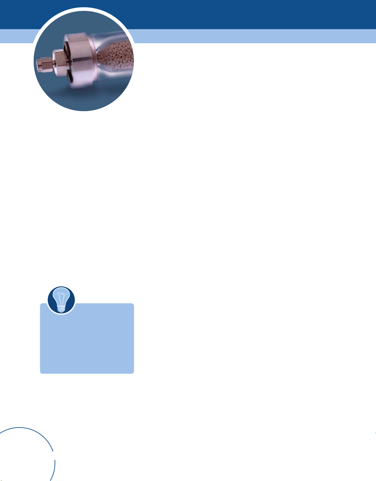
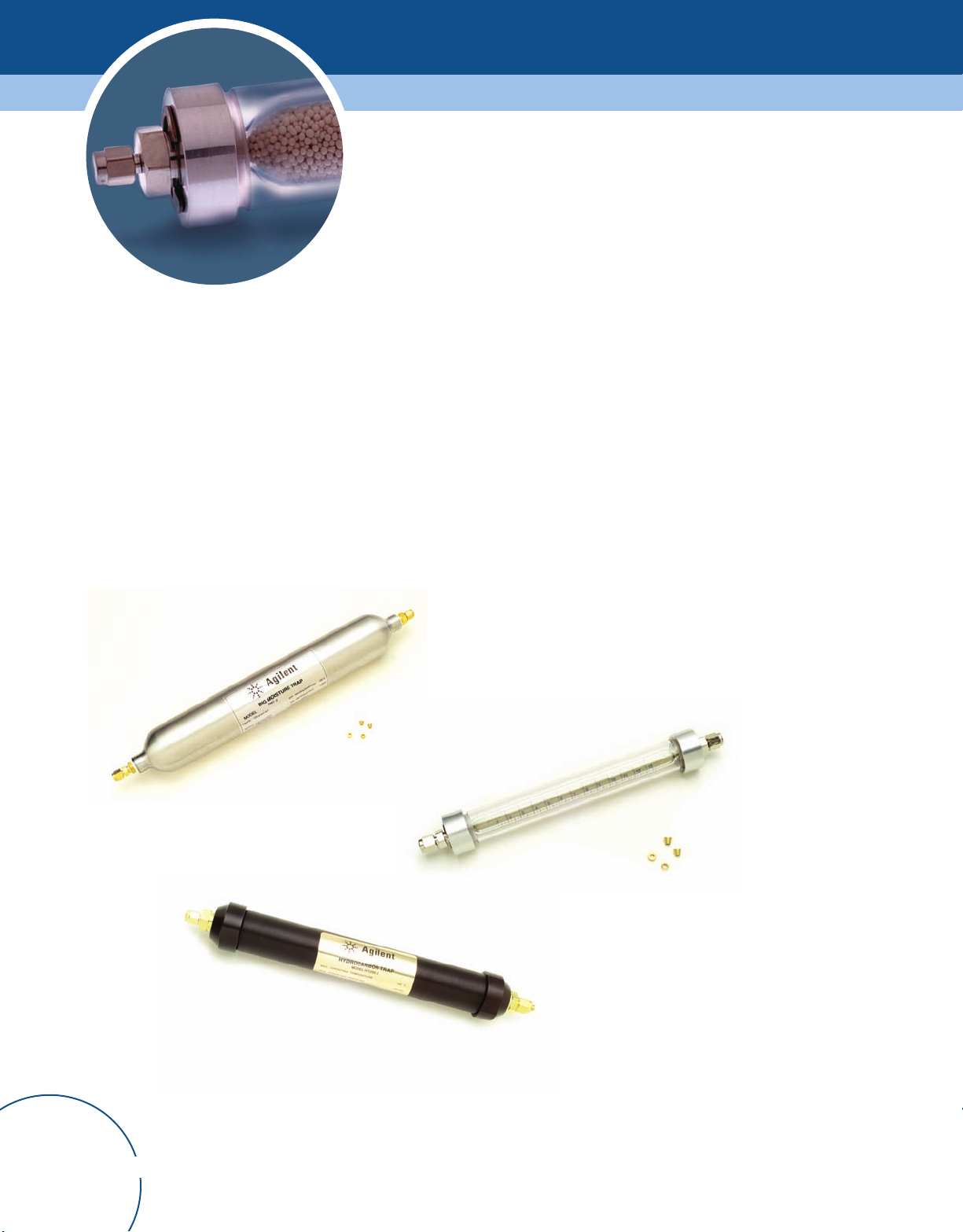
Gas Purification Systems
Purifiers are available in a variety of sizes and configurations to remove common
contaminants like oxygen, moisture, and hydrocarbons. In-line gas purifiers, including
refillable, indicating, S-shaped, and metal body types, are made to remove specific
.
contaminants. Agilent also offers gas purification systems with removable cartridges.
These systems provide the ability to design the right combination of filters needed
for your application to achieve the proper gas purity.
Page 7
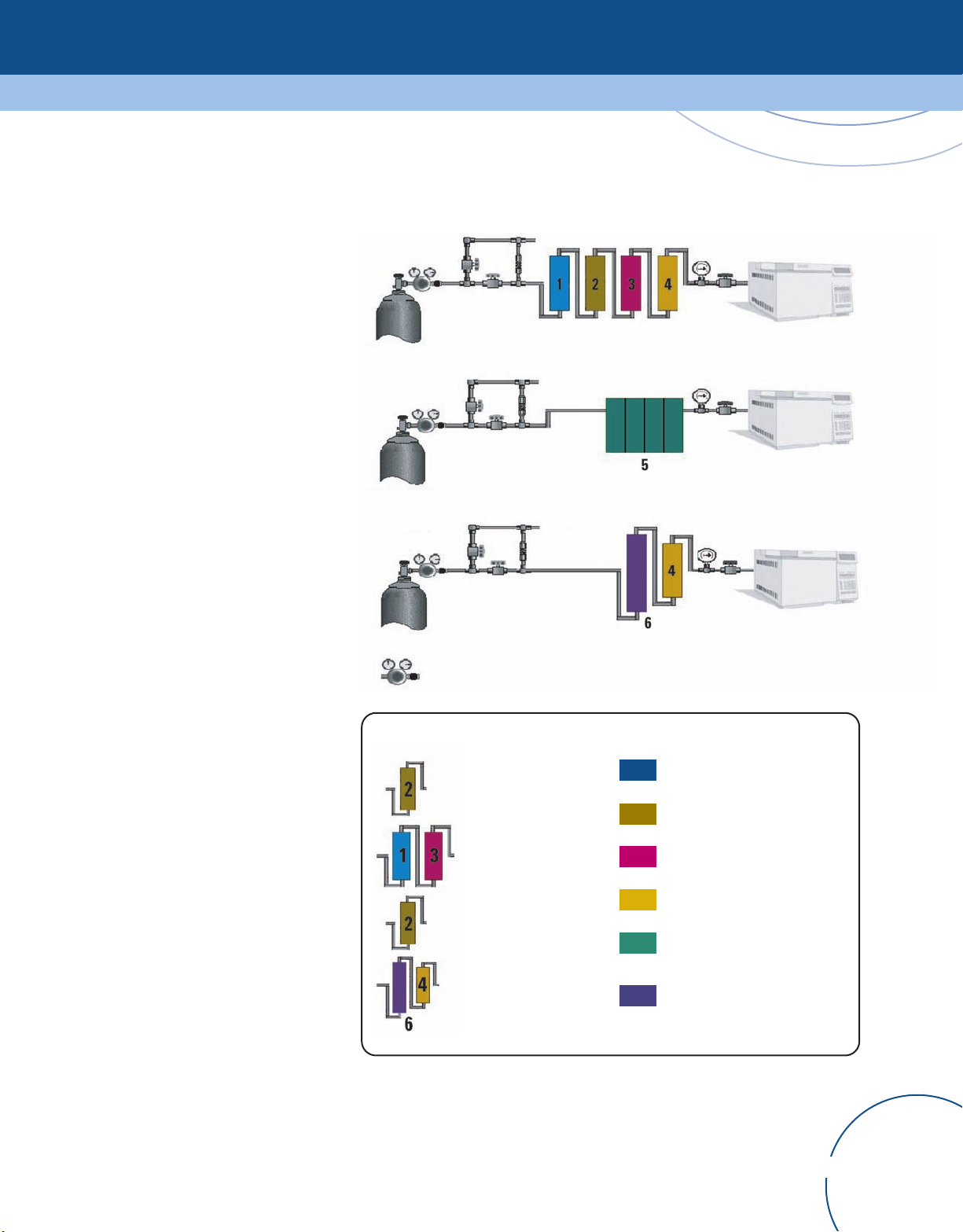
Carrier Gas Purification
Gas Management
The Carrier Gas Purification illustration
shows the most common gas purification
configurations used in gas chromatography.
Regardless of which purification
system is employed, proper installation
and maintenance is required to
achieve optimal performance from
the purification system(s). A purifier
that is not maintained will eventually
expire and become ineffective, or worse,
a source of contamination.
• Determine desired purity level.
• Keep number of fittings in gas line
to a minimum.
• Install purifiers in a convenient location
close to the GC.
• Purifier log books are useful for
determining maintenance schedule.
• Use indicating traps closest to the GC
so you can determine when to change
the traps that are upstream.
In-Line Gas Purifiers
-OR-
Gas supply
-OR-
Gas supply
Gas supply = cylinder, in-house line, or gas generator
Regulator = brass dual stage regulator
Gas Purification System
Combination Trap
Vent
FID make-up, air, and H
ECD make-up
ELCD reaction gas
MS carrier gas
KeyDetector Gas Purification
1 = Moisture Trap
2
Order online at www.agilent.com/chem/store
2 = Hydrocarbon Trap
3 = Oxygen Trap
4 = Indicating Oxygen T
5 = Gas Purification System
6 = Combination Trap for
moisture, oxygen, and
hydrocarbon removal
rap
5
Page 8
Gas Traps
The purpose of gas traps is to remove detrimental impurities from the carrier and detector
gases. Combination traps are available which remove moisture, oxygen and/or organics
with a single trap. The effectiveness of the traps depends on the initial quality of the gas.
Constant exposure of capillary columns to oxygen and moisture, especially at high
temperatures, results in rapid and severe column damage. The use of oxygen and
moisture traps for the carrier gas may extend column life and protect the instrument.
Any moisture or oxygen introduced into the gas stream due to a leak will be removed
by the trap until it expires.
Order online at www
6
.agilent.com/chem/store
Page 9

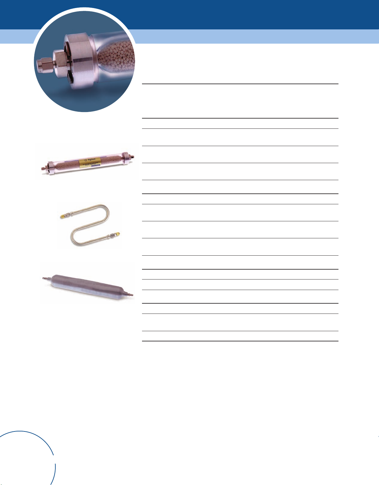
Moisture (Water) Traps
Indicating moisture traps are available in
plastic and glass bodies. Glass body traps
are used when potential contaminants
from plastic trap bodies are a concern.
Glass traps are normally encased in a
protective, plastic shrink wrap or a high
impact plastic shield (outer trap body).
Glass and plastic bodied traps are usually
pressure tested at 150 psi, thus they are
safe for use at the typical pressures
required by the GC.
Gas Management
oisture trap
M
Moisture Traps
Description Size
(cc)
Molecular Sieve 13X and Indicating 4A (MT Series)
Refillable
Moisture Trap
Refillable
Moisture Trap
Refillable
Moisture Trap
Adsorbent refill (1 pint) for MT series MSR-1 MSR-1
120 21.6 20 MT120-2 MT120-4
200 36.0 18 MT200-2 MT200-4
400 72.0 14 MT400-2 MT400-4
Removal
Capacity (g)
Max.
Effluent H
Concentration
(ppb)
O
2
1/8 in.
Part No.
1/4 in.
Part No.
Tips & Tools
Moisture traps are highly
recommended for carrier
and ECD gases.
Molecular Sieve 5A and Indicating Drierite (MT-D Series)
Refillable
Moisture Trap
Refillable
Moisture Trap
Refillable
Moisture Trap
Adsorbent Refill (1 pint) for MT-D Series MSR-2 MSR-2
120 21.6 22 MT120-2-D MT120-4-D
200 36.0 20 MT200-2-D MT200-4-D
400 72.0 16 MT400-2-D MT400-4-D
Order online at www.agilent.com/chem/store
7
Page 10
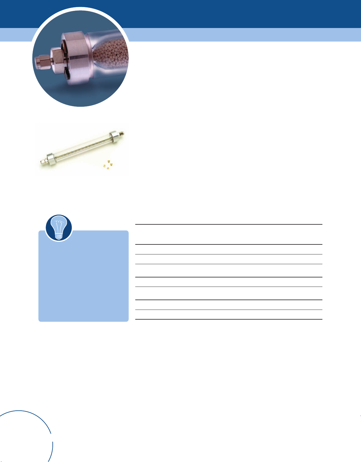
Moisture Traps
Refillable glass moisture trap
Moisture S-trap
Description Size
(cc)
Removal
Capacity (g)
Max.
Effluent H
oncentration
C
1/8 in.
Part No.
O
2
1/4 in.
Part No.
(ppb)
ilica Gel, Grade 40, and Indicating Silica Gel, Grade 48 (MT-S Series)
S
Refillable
120 31.5 40 MT120-2-S MT120-4-S
Moisture Trap
Refillable
200 52.5 39 MT200-2-S MT200-4-S
Moisture Trap
Refillable
400 105.0 39 MT400-2-S MT400-4-S
Moisture Trap
Adsorbent Refill (1 pint) for MT-S series SGR SGR
Glass Indicating Moisture Traps (GMT and LGMT Series)
Glass Indicating
70 11.4 7 GMT-2GC-HP GMT-4GC-HP
Moisture Trap
Glass Indicating
100 16.3 6 GMT-2-HP GMT-4-HP
Moisture Trap
Glass Indicating
250 40.09 6 LGMT-2-HP LGMT-4-HP
Moisture Trap
Molecular Sieve Refill for GMT and LGMT series GMSR GMSR
Big moisture trap
Moisture Removal S-Traps
Moisture S-trap, preconditioned* 5060-9084
Moisture S-trap, unconditioned 5060-9077
Big Moisture T
Big Moisture
rap
T
raps (BMT Series)
750 BMT-2 BMT-4
Refill for Big Moisture Trap (enough for 2 refills) BMSR-1 BMSR-1
*Traps can be reconditioned by heating at a minimum of 350°C, with flow for 6 hours
Order online at www
8
.agilent.com/chem/store
Page 11

Hydrocarbon Traps
Hydrocarbon traps remove organics,
such as hydrocarbons and halocarbons,
from the gas stream. The adsorbent is
usually activated carbon or an impregnated
carbon filter media. Carbon removes
organic solvents from the gas stream,
including the typical solvents used
in nearly every lab. Hydrocarbon-moisture
combination traps are also available which
remove water in addition to organics.
Capillary grade hydrocarbon traps are
purged with ultra-high helium and packed
with a very efficient activated carbon
material. Metal trap bodies are used to
prevent any contaminants in plastic trap
bodies from contaminating the carbon
adsorbent. Most hydrocarbon traps
can be refilled by the end user.
Gas Management
ydrocarbon trap, HT200-2
H
Hydrocarbon Traps
Description Size
Hydrocarbon Traps (HT Series)
Hydrocarbon Trap 200 HT200-2 HT200-4
Adsorbent Refill (1 pint) ACR ACR
Big Hydrocarbon Traps (BHT Series)
Big Hydrocarbon Trap 750 BHT-2 BHT-4
Refill for Big Hydrocarbon Trap (enough for two refills) BACR BACR
(cc)
1/8 in.
Part No.
1/4 in.
Part No.
Hydrocarbon Removal S-Traps
Hydrocarbon S-Trap, used for trapping organics from gases 5060-9096
Capillary Grade Hydrocarbon Traps (HT3 Series)
Capillary Grade Hydrocarbon Trap 100 HT3-2 HT3-4
Adsorbent Refill (1 pint) ACR ACR
Tips & Tools
Hydrocarbon traps should be used with carrier, FID and ELCD gases.
Order online at www.agilent.com/chem/store
9
Page 12
Indicating oxygen trap, IOT-2-HP
Oxygen Traps
Oxygen traps usually include a metal-containing inert support reagent. Most oxygen traps
reduce the oxygen concentration to below 15-20 ppb. The capacity of a standard oxygen
trap is approximately 30 mg of oxygen per 100 cc of trap volume. Oxygen traps can also
remove some small organic and sulfur compounds from gas streams, but this is not their
primary application.
Metal (usually aluminum) trap bodies are recommended for GC analyses. Some plastics
are permeable to air and contain contaminants that can degrade gas quality. In addition,
many of the metal bodied oxygen traps can withstand high pressures (up to 2000 psi).
Some oxygen traps also remove moisture from the gas stream without affecting the
oxygen removal capability.
Indicating oxygen traps change color when oxygen is present in the gas at harmful levels.
Indicating traps are not intended to be the primary oxygen removal trap, but should be
used in conjunction with a high capacity non-indicating oxygen trap. They are installed
after the high capacity oxygen trap in the gas line to indicate when the high capacity trap
has expired and needs to be changed. Expired oxygen traps need to be immediately
changed since they can contaminate the gas, in addition to failing to remove oxygen.
Oxygen Traps
Tips & Tools
Oxygen traps are critical on carrier
gas supplies to prevent column
bleed. They are also recommended
with ECD.
Description Size
Indicating Oxygen Traps (IOT and LIOT Series)
Indicating Oxygen Trap 30 IOT-2-HP IOT-4-HP
Large Indicating Oxygen Trap 150 LIOT-2 LIOT-4
Economy Non-Indicating Oxygen T
Oxygen Trap 70 OT1-2 OT1-4
Big Oxygen Traps (BOT Series)
Big Oxygen Trap 750 BOT-2 BOT-4
raps (OT1 Series)
(cc)
1/8 in.
Part No.
1/4 in.
Part No.
Order online at www
10
.agilent.com/chem/store
Page 13

Combination Traps
Agilent carries several Combination Traps
that provide multiple contaminant removal
in a single trap. These traps offer:
• Optimized adsorbents for maximum
surface area and capacity.
• Leak-free, one-piece design to eliminate
potential leaks from using multiple traps.
• Efficient design which prevents
channeling and promotes
efficient scrubbing.
The ultimate in purification with
•
the Big Universal Trap, which removes
oxygen, moisture, hydrocarbons,
carbon monoxide, and carbon dioxide.
Gas Management
Agilent OT3 trap
Combination T
Description Size
Oxygen/Moisture Traps (OT3 Series)
OT3 Trap 100 OT3-2 OT3-4
Hydrocarbon/Moisture Traps (HMT Series)
Hydrocarbon/Moisture Trap 200 HMT200-2 HMT200-4
Adsorbant Refill (1 pint) HCRMS HCRMS
raps
(cc)
1/8 in.
Part No.
1/4 in.
Part No.
Combination Traps for Chemical Ionization MS
Chemical Ionization for MS* G1999-80410
Big Universal Traps (RMS Series)
Hydrogen RMSHY-2
Helium (Ar/Me) RMSH-2 RMSH-4
Nitrogen RMSN-2 RMSN-4
*Isobutane or methane applications only
RMSHY-4
Order online at www.agilent.com/chem/store
11
Page 14
NEW!
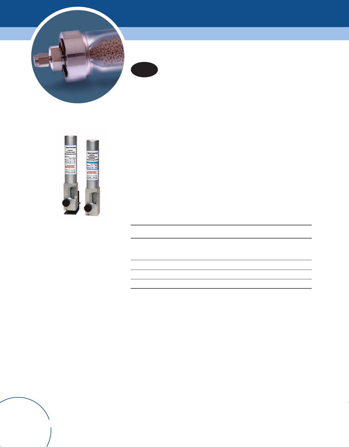
Renewable Gas Purification System
The Renewable Gas Purification System from Agilent not only traps large quantities of
contaminants and lasts a long time, but it is also recyclable. With average use, you'll only
have to purchase a replacement cartridge once per year or after approximately 20
cylinders worth of purification. And when you need a replacement, you have the option to
purchase a new or recycled cartridge. Recycled cartridges are refilled and certified to the
full specification of the new cartridges.
• All cartridges are environmentally friendly and reduce waste.
• High capacity – 850cc or more Oxygen filtration, 12g H
O, and approximately 8g
2
hydrocarbon filtration per cartridge – in a compact footprint.
• Improves 99.995% gas purity to 99.9995% purity.
• Dual indicators make it easy to see the purification results.
• Labeling displays indicator color and shape for accurate reading.
• Simple twist on/off knob and guide rod make cartridge changes quick and easy.
• One Renewable Purifier system can support up to four GC systems.
• Designed with efficiency, safety, and environmental responsibility in mind.
Renewable gas purification system
Renewable Gas Purification System
Description Part No.
Renewable gas purifier system startup kit
Includes one G3440-80007 base, one G3440-60003 renewable gas purifier
cartridge, and wall or bench mount hardware.
Renewable gas purifier system, base only G3440-80007
Renewable gas purifier cartridge, new G3440-60003
Renewable gas purifier recycled cartridge G3440-69003
G3440-60004
Order online at www
12
.agilent.com/chem/store
Page 15

Gas Management
Universal/External Split Vent Trap
Split vent traps stop environmental pollution. The split vent trap was designed to protect
the lab environment from the contaminants released by split injection systems, which can
vent up to 500 times the amount of sample reaching the detector into the laboratory's air.
A replaceable, impregnated carbon filter media traps and eliminates a broad range of
contaminants. The traps are also easy to change and come with three packs of
replacement cartridges each. Replace approximately every six months.
Split vent trap and cartridges, RDT-1020
Universal/External Split Vent Trap
Description Part No.
Universal/external split vent trap with 3 cartridges, 1/8 in. Swagelock fitting RDT-1020
Replacement cartridges, 3/pk RDT-1023
Split vent trap kit G1544-60610
ools
ips & T
T
Replace split vent traps every six months.
Order online at www.agilent.com/chem/store
13
Page 16
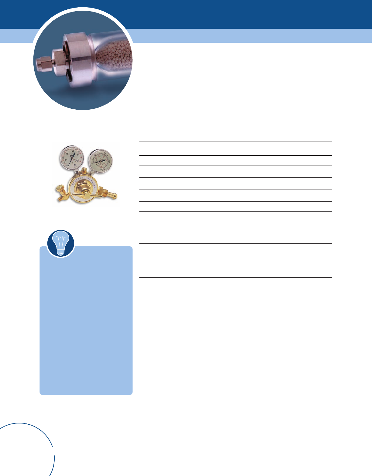
Regulators
Agilent recommends using our economical brass body, dual stainless steel diaphragm
regulators for most GC applications. These regulators, combined with the proper
gas purification system, provide proper gas pressure control and purity for
gas chromatography.
Brass Body, Dual Stainless Steel Diaphragms, 1/8 in., U.S. Only*
Description Part No.
CGA 346, 125 psig max (8.6 bar), Air 5183-4641
CGA 350, 125 psig max (8.6 bar), H2, Ar/Me 5183-4642
Brass body regulator
Tips & T
ools
When ordering a regulator, be sure
to specify the proper connections.
In the US, most gas manufacturers
follow CGA connection guidelines.
In Europe, there are a number of
organizations designating cylinder
connections that are specific to
individual countries. It is best
to contact your local supplier for
the proper connection designation.
CGA 540, 125 psig max (8.6 bar), O
CGA 580, 125 psig max (8.6 bar), He, Ar, N
CGA 590, 125 psig max (8.6 bar), Air 5183-4645
*For 1/4 in. tubing, purchase a 1/4 in. adapter, U.S. only
2
2
5183-4643
5183-4644
Connectors (Swagelok to Female NPT)
Description Unit Part No.
1/8 in. (A) x 1/4 in. (B) connector, brass (included with brass regulators)
1/4 in. (A) x 1/4 in. (B) connector, brass* 1/ea 0100-0119
*Required for plumbing 1/4 in. tubing to regulators
1/ea 0100-0118
Order online at www
14
.agilent.com/chem/store
Page 17
Tubing
Gas Management
Cleaning Tubing
Before any tubing is placed into service,
or if it becomes contaminated with use,
it is essential that it be properly cleaned.
Unclean or improperly cleaned tubing can
lead to contamination of the system with
disastrous results. Never use chlorinated
solvents to clean tubing or fittings.
Agilent provides clean, high quality
GC grade tubing for large systems as
an economical alternative.
Agilent recommends using copper tubing for most applications, since it is easy to bend
and plumb and is less expensive than stainless steel. Use stainless steel tubing only for
crucial applications that require very high purity, or where building codes mandate its use.
Determining Tubing Length
Parameters: 2000 sccm (4.2 scfh); Temperature: 70°F; Pressure 30 psig
Tubing Type Diameter
(inches)
Copper 1/8 50 2
Copper 1/4* 300 0.5
*Recommended when multiple instruments are connected to the same source
Recommended
Max. Length (feet)
Pressure Drop
(psig)
Tubing - Precleaned
Description Part No.
Copper tubing, 1/8 in., 50 ft 5180-4196
Copper tubing, 1/8 in., 12 ft 5021-7107
Fittings
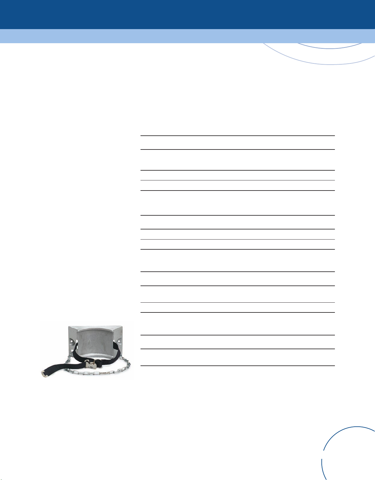
Cylinder wall bracket, 5183-1941
Description Part No.
Fittings Kit
Includes brass nuts, ferrules, caps, plugs, unions and reducers
1/8 in. brass nut and ferrule set 5080-8750
5180-4161
Cylinder wall bracket
Description Part No.
Cylinder wall bracket with strap & chain
(cylinder size up to 14 in., 35 cm)
Order online at www.agilent.com/chem/store
5183-1941
15
Page 18
Flowmeters
Setting and maintaining GC flow rates greatly affects the instrument accuracy
and sensitivity. During maintenance, verify carrier and support gas flows with
the proper flowmeter.
Precision gas flow meter, 5067-0223
NEW!
Agilent's Precision Gas Flow Meter is the ultimate gas flowmeter for chromatography
applications. This hand-held flowmeter incorporates industry leading performance and
features in a highly accurate and reliable package. The inherent stability of the rugged,
solid state components allows us to provide the longest calibration interval on the market,
all traceable to NIST standards.
• Highly accurate and reliable measurement of common carrier and fuel gases used
in GC, including nitrogen, air, carbon dioxide, hydrogen, helium, and argon/methane.
• Two year guaranteed calibration period traceable to NIST standards.
• Measures flow (0-500 mL/min.) based on gas viscosity properties with an accuracy
of ± 0.8% of reading + 0.2% of full scale.
• Flow rate range from 0-500 mL/min (no conversion necessary from SCCM) eliminates
the need for two separate meters to measure capillary and standard flows.
• Displays mass flow, volumetric flow, temperature, and pressure
readings simultaneously.
• Can be plumbed inline.
Precision Gas Flow Meter
Precision Gas Flow Meter
Description Part No.
Order online at www
16
Precision gas flow meter 5067-0223
.agilent.com/chem/store
Page 19

ADM flowmeters
Gas Management
ADM 1000
• Accuracy ± 3%.
• Operating temperature range – 0 to 45ºC for the instrument, -70 to 135ºC
for the tubing.
• Calibration – traceable to NIST primary standards.
• Real time, split ratio measurement.
• CE mark certified.
• Measures flow rates from 0.5 to 1000 mL/min.
• Split ratios – compare the ratio from one gas measurement to another
(i.e., injection port split ratios).
ADM 2000
In addition to the features of the ADM 1000, the ADM 2000 includes:
• Mass flow measurements – measure flow rate, independent of atmospheric pressure
and temperature (calculated).
• Data output through RS-232 port.
• 9V battery and AC power adapter (120 or 220 VAC).
ADM Flowmeters
Description Flow Rate
(mL/min)
Low High
ADM 1000** 0.5 1000 All ± 3 9V Battery None 220-1170
ADM 2000** 0.5 1000 All ± 3 Battery or 120V AC Yes 220-1171-U
ADM 2000E** 0.5 1000 All ± 3 AC Adapter, 220V Yes 220-1171-E
Carrying Case for ADM 907-0056
*± 3% or ± 0.2 mL/min, whichever is greater with a flow rate of 0.5 - 1,000 mL/min
**Non-corrosive gases only
Gases
Measured*
Accuracy (%) Power
Supply
RS-232
Data Output
Part No.
Order online at www.agilent.com/chem/store
17
Page 20
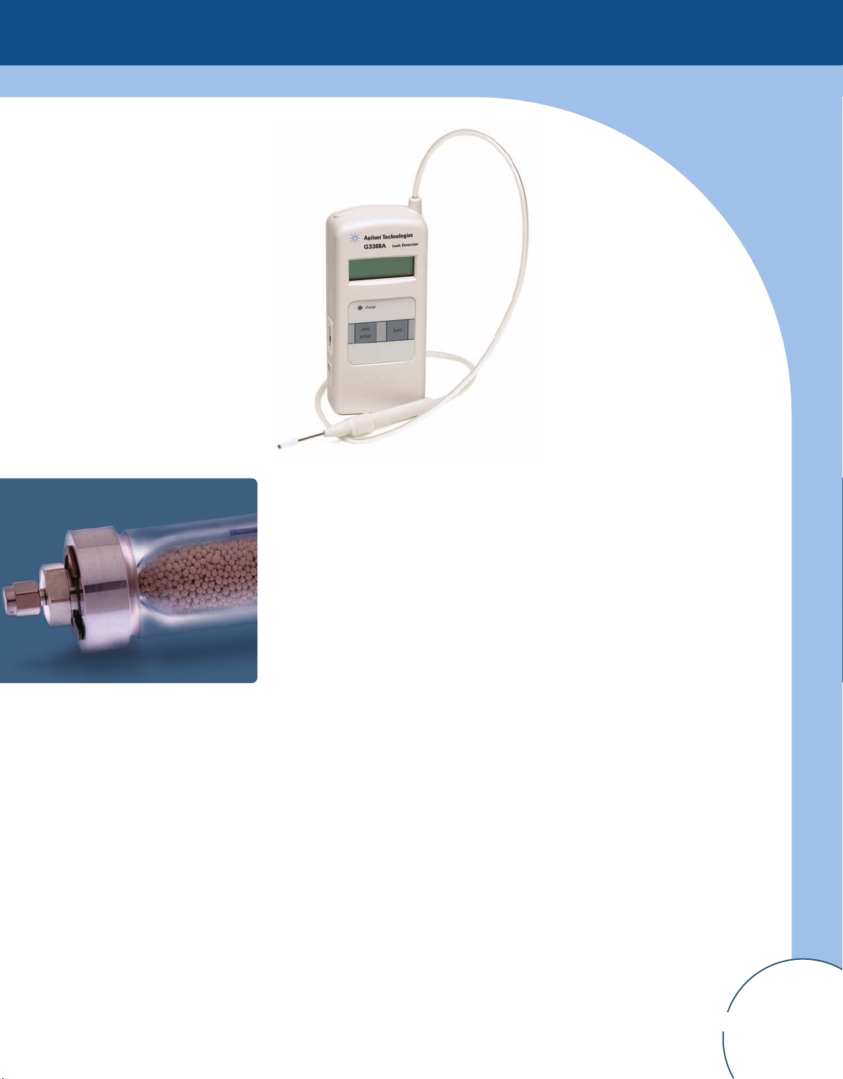
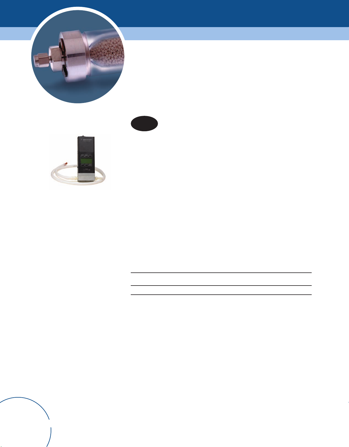
NEW!
Gas leaks can cause detector noise and baseline instability, shorten column life and waste
expensive carrier gas. Liquid leak detectors, although inexpensive, can contaminate your
system. Agilent's G3388A electronic leak detector is an easy way to quickly identify leaks
in your system.
Gas Leak Detector
Gas Leak Detector
Description Part No.
Gas leak detector
Handheld electronic gas leak detector
Includes probe, unit, AC power adapter/battery charger, battery, and user manual.
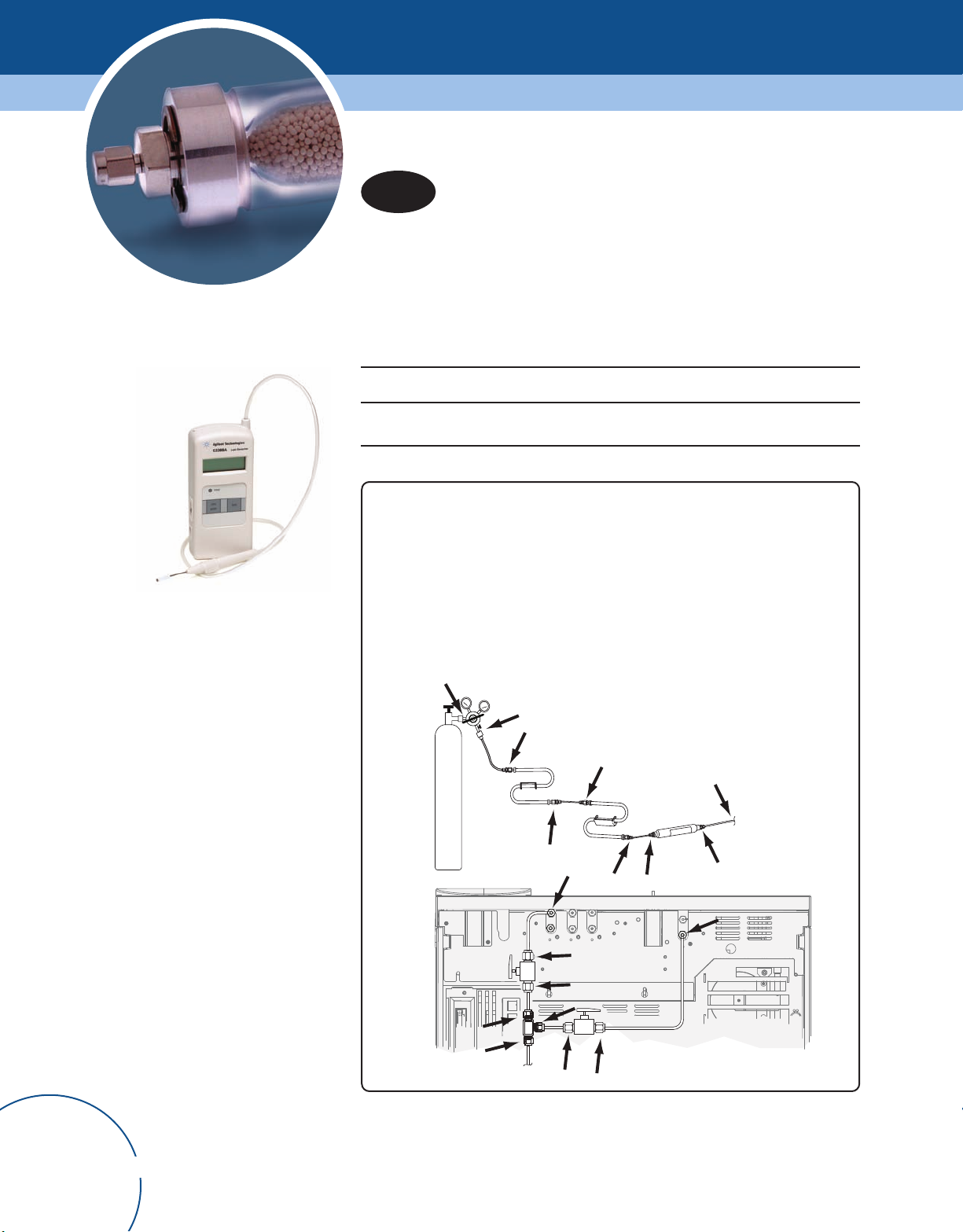
Check valves, fittings, and traps for leaks after every maintenance and thermal
cycling, as these can loosen some types of fittings.
Check for leaks at these connections:
• Gas supply bulkhead fittings
• Gas cylinder fitting
• Regulator fittings
• Traps
• Shut-off valves
• T-fittings
G3388A
Order online at www
18
.agilent.com/chem/store
Page 21
Sample Introduction
Ensure optimal peak shape and reproducibility
through accurate sample delivery.
They may be small, but sample introduction supplies can have a profound impact on
your results. That is why Agilent vials, septa, and syringes are meticulously engineered
to work seamlessly with your GC and GC/MS instruments. They can help you achieve
reliable, repeatable results even for your most complex runs.
This section guides you through…
• The selection, use, and maintenance of your essential sample introduction supplies.
• Troubleshooting common and unusual syringe problems.
• Essential procedures, such as vial filling, syringe cleaning, and choosing the right
septa material for your application.
Order online at www
.agilent.com/chem/store
19
Page 22

Vials
Agilent's wide opening vials are designed specifically for analyzing samples with your GC.
They have specially designed vial neck angles, bottom design, and height to ensure
compatibility with Agilent autosamplers with rotating or robotic arm trays. Agilent offers
a large variety of autosampler vials in different closures, cap colors, septa choices,
and package options. Agilent also offers convenience packs with 500 vials and caps
in a reusable blue storage box.
For small samples sizes, Agilent offers a variety of options. You can use microvolume
inserts with the wide opening vials or, for added convenience, use vials with small
volume capacity.
Vial Options
Agilent Certified Vials
Agilent certified vials undergo
stringent testing of critical
dimensions to ensure that each
vial works flawlessly with your GC
and GC/MS systems. Additionally,
each certified vial is made from
first hydrolytical class, borosilicate
glass type 1 then packed in a
clean, sealed environment to
prevent contamination.
Glass - for general purpose
use and for use with acids
Polypropylene - for use with
alcohols and aqueous solvents
Amber Vials - for use with
light-sensitive samples
Silanized - for use with
samples that bind to glass,
and for trace analysis
High Recovery Vials for use with limited sample vials
Microvolume Inserts for use with very small
sample volumes
Order online at www
20
.agilent.com/chem/store
Page 23
Sample Introduction
Vial Filling
When filling sample vials, keep in mind:
• If you need to test a large amount of sample over repeated injections, divide the sample
among several vials to obtain reliable results.
• When sample volume in the vial is low, contaminants from the previous sample
injection or solvent washes may have a greater impact on the sample.
The airspace in the vial is necessary to avoid forming a vacuum when sample
is withdrawn. This could affect reproducibility.
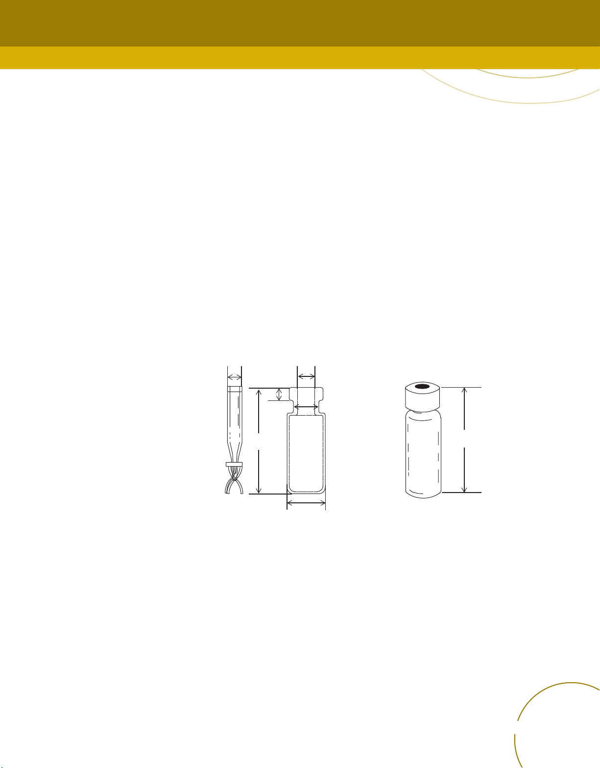
Preparing Sample V
ials
The Agilent 7683 Automatic Liquid Sampler Injector and the tray use clear or amber
glass sample vials with crimp, snap, or screw top vials. The following diagram shows
the critical dimensions for sample vials and microvial inserts to be used with the 7683
Automatic Liquid Sampler. These dimensions do not make up a complete set of
specifications. Incompatible sample vials cause tray and turret errors.
5 minimum 6.25
3.7
8.2
32
11.7
Microvial insert Crimp cap sample vial Maximum height of a capped vial
All dimensions in millimeters
34.5 maximum
Order online at www.agilent.com/chem/store
21
Page 24

Selecting Vial Septa Materials
Vial cap septa are critically important to optimal analysis. Each septum complements
the overall system and enhances chemical performance. Agilent's vial cap septa are
specifically formulated and constructed for optimum system performance, with minimal
coring and superior chemical inertness.
Type Uses
Tips & Tools
To determine potential septa
quantities, consider:
• The number of samples
run during a day/week.
If samples are run in small
•
or large batches.
• If samples are run manually
or with an autosampler
• If samples are run overnight,
unattended.
.
Red Rubber/PTFE
Silicone/PTFE
PTFE/Silicone/PTFE
PTFE Disc
Viton
• Routine analysis
• Moderate resealing
• Excellent chemical inertness
• Not recommended for multiple injections or storage of samples
• Least expensive
• Excellent resealing
• Resists coring
• Good for multiple injections
• Used in trace analysis applications
• Above average resealing
• Most resistant to coring
• Least evaporation
• Use with large diameter, blunt tip syringe needles
• Good for MS and ECD analysis
• Good for large-volume injections
• Chemically inert
• No resealing
• Single injection
• No long-term sampling storage
• Chlorinated solvents
• Organic acids
• Limited resealing
• Not suitable for 32 guage syringe
Order online at www
22
.agilent.com/chem/store
Page 25

onvenience vial and cap pack
C
Sample Introduction
Convenience Vial and Cap Packs
Vials Caps Unit Part No.
Certified Screw Top Vial Convenience Packs
Clear Blue screw caps, PTFE/red
ubber septa
r
Clear with write-on spot Blue screw caps, PTFE/red
rubber septa
Amber with write-on spot Green screw caps, PTFE/red
rubber septa
Clear Blue screw caps,
PTFE/silicone/PTFE septa
Clear with write-on spot Blue screw caps,
PTFE/silicone/PTFE septa
Amber with write-on spot Green screw caps,
PTFE/silicone/PTFE septa
Clear Blue screw caps, PTFE/silicone
septa
Clear with write-on spot Blue screw caps, PTFE/silicone
septa
Amber with write-on spot Green screw caps, PTFE/silicone
septa
Clear Blue screw caps, pre-slit
PTFE/silicone septa
Clear with write-on spot Blue screw caps, pre-slit
PTFE/silicone septa
Amber with write-on spot Green screw caps, pre-slit
PTFE/silicone septa
Clear Blue screw caps, pre-slit
PTFE/silicone septa
500/pk 5182-0732
500/pk 5182-0867
500/pk 5182-0733
500/pk 5182-0736
500/pk 5182-0869
500/pk 5182-0737
500/pk 5182-0734
500/pk 5182-0868
500/pk 5182-0735
500/pk 5183-2079
500/pk 5183-2080
500/pk 5183-2081
500/pk 5067-0205
Order online at www.agilent.com/chem/store
23
Page 26
Certified crimp top vial convenience pack
Convenience Vial and Cap Packs
Certified Crimp Top Vial Convenience Packs
Clear Silver aluminum crimp caps,
PTFE/red rubber septa
Amber with write-on spot Silver aluminum crimp caps,
PTFE/red rubber septa
Snap Top Vial Convenience Packs
Clear Clear polypropylene snap caps,
PTFE/red rubber septa
Amber, with write-on spot Clear polypropylene snap caps,
PTFE/red rubber septa
500/pk 5181-3400
500/pk 5181-8801
500/pk 5182-0547
500/pk 5182-0548
Order online at www
24
.agilent.com/chem/store
Page 27

lectronic crimper, 5062-0207
E
Sample Introduction
Electronic Crimpers and Decappers
Whenever large amounts of crimp vials need to be crimped or decapped,
the electronic crimper or decapper is the right tool. It reduces stress and repetitive
motion injury associated with manual plier-style crimpers and decappers. Agilent's
newly-designed crimper offers easy, hand-held pushbutton operation and provides the
following advantages:
• Stronger and sturdier crimping and decapping.
• Consistent seals.
Shorter recharging time and a larger number of battery charges.
•
• Better clearance and more flexibility thanks to improved crimp jaws.
• Individual test certificates.
Electronic Crimpers and Decappers
Description Part No.
11 mm Electronic Crimper with 4.8v rechargeable battery pack and charger 5062-0207
20 mm Electronic Crimper with 4.8v rechargeable battery pack and charger 5062-0208
11 mm Electronic Decapper with 4.8v rechargeable battery pack and charger 5062-0209
20 mm Electronic Decapper with 4.8v rechargeable battery pack and charger 5062-0210
4.8v nickel metal hydride replacement battery 5188-6565
Tips & Tools
For a consistent seal, make sure there are no folds or wrinkles
on the part of the cap that wraps under the neck of the vial.
Order online at www.agilent.com/chem/store
25
Page 28

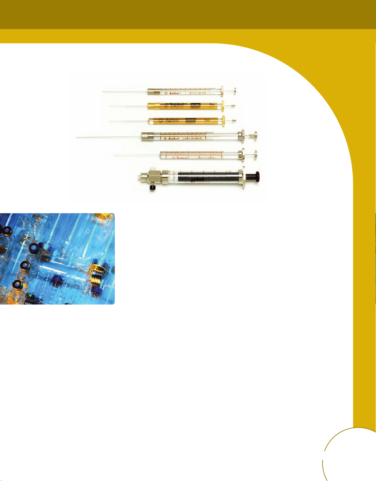
Gold standard autosampler syringes
Gold Standard Autosampler Syringes
With a broad selection of syringes for auto injection, Agilent has what you need for
accurate and effective sampling. Agilent delivers even more value in every autosampler
syringe with the introduction of many new features in our line of Gold Standard GC
Autosampler Syringes.
Agilent Gold Standard Autosampler syringes are designed:
• For reproducible sample volume delivery.
• Specifically for the Agilent inlet or autosampler.
• To maximize inlet septum lifetime.
Agilent Gold Standard Autosampler syringes feature:
• Lot numbers printed directly on the barrel with a corresponding Certificate of
Conformance ensuring certified performance to all specifications.
• Gold protective cap on the fused needle, preventing the glass syringe barrel from
chipping as it is pressed against the inlet.
• Black ink and gold illuminating backing strip, for effortless viewing of the volume scale,
which is easily discernible from imitators.
• Environmentally friendly packaging, an improved design that reduces waste.
• Individually sealed packaging, for contaminant-free use right out of the box.
Order online at www
26
Tips & Tools
Use syringe needles with an Agilent dual-taper needle or a conical tip. Sharptipped needles tend to tear the inlet septum and cause leaks. Also, a sharptipped needle tends to leave residual amounts of sample on the septum as it
exits, resulting in a large solvent tail on the chromatogram.
.agilent.com/chem/store
Page 29

Sample Introduction
Needle Gauge Selection
• Syringe needles compatible with Agilent Automatic Liquid Samplers are 42 mm long
and have an HP style or cone shaped tip.
• The Merlin Microseal requires 23 gauge needles.
• The smaller the gauge, the larger the needle diameter.
Needle Gauge Selection
Inlet Needle Gauge Column Type
Tips & Tools
For highest productivity and
to minimize coring, use Agilent
Premium Non-Stick Inlet Septa
with Center Point Guide.
See page 46.
Packed, split or splitless (including
PTV)
Cool on-column 23/26 gauge tapered or 26 gauge 530 µm
Cool on-column 26/32 gauge tapered 320 µm
Cool on-column 26/32 gauge tapered 250 µm
Needle Tip
Cone tip
Needle Shape
23 gauge or 23/26 gauge tapered Any
Needle tips
Tapered needle
Order online at www.agilent.com/chem/store
27
Page 30

Syringe Characteristics and Recommended Uses
Syringe Advantage Limitations Recommended Use
10 µL, PTFE-tipped
10 µL, fitted plunger
5 µL, fitted plunger
• Less plunger binding than fitted
plunger
• Replaceable plunger for reduced
repair cost
• Tight seal between plunger and barrel
• Most economical
• Most reliable fitted plunger syringe
• Less bending
• Better for high viscosity samples
• Most accurate for 1 µL injection
• No hardware modification needed for
0.5 µL
• More expensive than fitted plunger
• PTFE-tipped syringes not available
in 5 µL size
• Most accurate only for 1 µL and
larger injections
• Plunger not replaceable
• Thinnest plunger, can bend more
easily
• Not ideal for higher viscosity
samples
• Plunger not replaceable
• High sample throughput
• Samples in polar solvents
• Dirty samples
• Gases and volatile samples
• Reactive samples
• General purpose syringe
• Clean samples
• Routine analysis
• 1 µL injections
• Clean samples
• Routine analysis
Order online at www
28
.agilent.com/chem/store
Page 31

Sample Introduction
Syringe Troubleshooting Guide
Proper care, cleaning, and handling of each syringe will help ensure correct performance and long life. When cleaning your syringe,
it is best to use solvents that effectively dissolve the sample you are working with. Try to avoid cleaning agents that are alkaline, contain
phosphates, or are strongly acidic.
Problem Possible Cause(s) Suggested Action(s)
Bent plungers or stuck syringes
Bent needles
• Particles such as dust, leftover samples, salts,
metal, or glass can fill the narrow gap between the
plunger shaft and the inside wall of the barrel.
• Improper needle alignment.
• Narrow-gauge needles (26 gauge) bend more
easily than larger (23 gauge) needles.
• Needles tend to bend when inserted into the
sample vial - not the inlet port. This can be caused
by septa that are too "tough."
• If the needle has been slightly bent when mounted
in the autosampler - or when the syringe is
installed into the autosampler - then it is more likely
to bend further when it pushes through the septa
on the sample vial caps.
• Try PTFE-tipped plunger syringe.
• If the plunger's movement feels "gritty," remove the
plunger from the barrel, flush the shaft with
solvent, and wipe it dry with a lint-free cloth. Then,
carefully insert the plunger back into the barrel.
Finally, submerge the tip of the needle into a
container of solvent, and cycle the plunger to pull
the solvent into and out of the barrel.
• Never cycle the plunger in a dry syringe.
• Do not "mix & match" plungers and barrels.
• Always clean syringes after use immediately.
• Use only Agilent autosamplers.
They are precision-designed to ensure proper
alignment with the Agilent inlet.
• Use 23 to 26-gauge tapered needles to get the
combined benefits of greater septa life and fewer
bent needles.
• Only use Agilent vials and septa.
Order online at www.agilent.com/chem/store
29
Page 32

Problem Possible Cause(s) Suggested Action(s)
Blocked needles
Rust
Note: even minor rust can cause the
plunger to become stuck in the barrel.
"Ring around the neck"
(A dark ring between the top
of the barrel and the end of
the volume scale.)
Loose plungers
Accompanied by syringe leaks and
area count reproducibility problems.
• Sample material or contaminants may be trapped
inside the needle.
• The needle may not have been properly cleaned.
• During normal use, the shaft rubs against the glass
walls of the barrel. This gradually wears away the
rust-resistant metal on the shaft's surface.
• Rusting happens most rapidly when using water or
solvents that may contain (or absorb) water.
• Skin oils and other organic material.
• Fine metal and glass particles from the syringe
plunger and barrel may be rubbing together. Once
this happens, the plunger may bend if used further.
Remove the plunger and use a second syringe to fill
the blocked syringe with solvent. Then, insert the
plunger and gently push solvent through needle.
Important: Try to use a cleaning agent that is
appropriate for the contaminant. Common choices
are methanol, methylene chloride, acetontrile,
and acetone.
To slow this process, remove the water from the
syringe at the end of each day.
1. Rinse the syringe several times with a "dry"
solvent, such as acetone.
2. Remove the syringe from the autosampler,
and wipe the plunger dry with a lint-free cloth.
3. Let syringe and plunger air dry.
• Never touch the plunger shaft with your fingers.
• If build-up appears when water is the solvent:
rinse syringe with acetone and wipe the plunger
clean at the end of each day.
• The syringe is nearing the end of its useful life. • Replace the syringe.
• Note: Plungers normally feel "loose" when non-
polar solvents (like hexane and toluene) are used.
Order online at www
30
.agilent.com/chem/store
Page 33

18.5 mm
mL fill volume
4
2.0 mL usable
olvent volume
s
Minimum solvent level
2.0 mL solvent
remains
Sample Introduction
Cleaning Syringes During an Autosampler Sequence
To ensure the syringe is properly cleaned between injections, rinse and fill each solvent
bottle with 4 mL of fresh solvent. The liquid level will be near the shoulder of the bottle.
Good laboratory practice dictates using no more than 2 mL of the 4 mL solvent for syringe
washes. The needle tip draws solvent 18.5 mm from the bottom of the vial.
Tapered Needle, 23-26s Gauge Autosampler Syringes
Volume
(µL)
Description Unit Needle Part No.
eedle tip position when withdrawing solvent
N
Tips & Tools
When cleaning syringes between
injections, use Agilent wash vials
(p/n 9301-0723) and diffusion
caps (p/n 07673-40180).
5 Tapered, fixed 23-26s/42/HP 5181-1273
Tapered, fixed 6/pk 23-26s/42/HP 5181-8810
Tapered, removable 23-26s/42/HP 5182-0835
Replacement needle for 5 µl syringe 3/pk 23-26s/42/HP 5182-0832
10 Tapered, fixed 23-26s/42/HP 5181-1267
Tapered, fixed 6/pk 23-26s/42/HP 5181-3360
Tapered, removable 23-26s/42/HP 5181-3321
Replacement needle for 10 µl syringe
Tapered, fixed, PTFE-tipped plunger 23-26s/42/HP 5181-3354
Tapered, fixed, PTFE-tipped plunger 6/pk 23-26s/42/HP 5181-3361
Replacement plunger with PTFE tip
for fixed needle 10 µl syringe
Tapered, removable 23-26s/42/HP 5181-3356
Replacement plunger with PTFE tip
for removable needle 10
50 Tapered, fixed, PTFE-tipped plunger 23-26s/42/HP 5183-0314
100 Tapered, fixed, PTFE-tipped plunger
µl syringe
3/pk 23-26s/42/HP 5181-3319
5181-3365
5181-3358
23-26s/42/HP 5183-2042
Order online at www.agilent.com/chem/store
31
Page 34

Straight Needle, 23 and 26s Gauge Autosampler Syringes
Volume
(µL)
0.5 Cone-tipped, 23 gauge 23/42/HP 5188-5246
1 Cone-tipped, 23 gauge 23/42/HP 5188-5247
5 Straight, fixed, 26 gauge 26s/42/HP 9301-0891
10 Straight, fixed, 26 gauge 26s/42/HP 9301-0714
25 Straight, fixed, PTFE-tipped plunger 23/42/HP 5183-0316
50 Straight, fixed, PTFE-tipped plunger 23/42/HP 5183-0318
100 Straight, fixed, PTFE-tipped plunger 23/42/HP 5183-2058
Description Unit Needle Part No.
Straight, fixed, 26 gauge 6/pk 26s/42/HP 5183-4728
Straight, fixed, 23 gauge 23/42/HP 9301-0892
Straight, fixed, 23 gauge 6/pk 23/42/HP 5182-0875
Straight, removable, 23 gauge 23/42/HP 5182-0834
Replacement needle for 5 µl syringe 3/pk 23/42/HP 5182-0830
Straight, fixed, 26 gauge 6/pk 26s/42/HP 5183-4729
Straight, fixed, 23 gauge 23/42/HP 9301-0713
Straight, fixed, 23 gauge 6/pk 23/42/HP 9301-0725
Straight, fixed, PTFE-tipped plunger 23/42/HP 5181-8809
Straight, fixed, PTFE-tipped plunger 6/pk 23/42/HP 5183-4730
Replacement plunger for 10 µl fixed
needle syringe
Straight, removable, 23 gauge 23/42/HP 5181-8806
Straight, removable, PTFE-tipped plunger 23/42/HP 5181-8813
Replacement needle for 10 µl syringe 3/pk 23/42/HP 5181-8811
Replacement plunger with PTFE tip
l syringe
for removable needle 10
µ
5181-8808
5181-3358
Order online at www
32
.agilent.com/chem/store
Page 35

Sample Introduction
GC Automatic Liquid Sampler Supplies
Description Unit Part No.
4 mL Clear screw top wash vials with screw caps (no septa) 144/pk 9301-0723
epta for 4 mL vial 144/pk 9301-1031
S
Diffusion inserts for 4 mL vials 12/pk 07673-40180
4 mL wash vials with fill markings and caps 25/pk 5182-0551
Screw for mounting syringe 07673-20570
Quadrant tray (4 tray sections) 18596-40015
7673 Basic Supply Kit
Contains 10 µL syringes (6/ea), 23/26 gauge needles, 4 mL vials with
diffusion caps (144/pk), 2 mL automatic sampler vials with screw caps
(1,000/pk), GC septa (25/pk), vial racks (5/pk)
07673-60840
Order online at www.agilent.com/chem/store
33
Page 36

Headspace Sampler
The appropriate maintenance frequency for the Headspace Sampler varies significantly
depending on the sample matrix, solvents, temperatures, and sample throughput.
Recommended Maintenance Schedule
G1888 Headspace sampler
Maintenance
Activity
Replace sample
probe
Steam clean 6 months 3 months 3 months Every month
Replace loop and
deactivated tubing
Check tray tension
and alignment
PM for headspace
and inlet
Extended PM
for headspace
Low Boiling Solvents
(water, food, flavor analyses)
≤ 70
samples/day
6 months 3 months 3 months Every month
With PM With PM With PM 6 months
12 months 6 months 12 months 6 months
36 months 12 months 12 months 6 months
60 months 36 months 24 months 12 months
> 70
samples/day
High Boiling Solvents
(OVI, blood alcohol analysis)
≤ 70
samples/day
> 70
samples/day
Order online at www
34
.agilent.com/chem/store
Page 37

ertified headspace vials
C
Sample Introduction
Headspace Vials
Description Unit Part No.
Certified Flat Bottom Headspace Crimp Top Glass Vials
20 mL, clear, 23 x 75 mm 100/pk 5182-0837
10 mL, clear, 23 x 46 mm 100/pk 5182-0838
Certified Rounded Bottom Headspace Crimp Top Glass Vials
20 mL, clear, 23 x 75 mm 100/pk 5183-4474
10 mL, clear, 23 x 46 mm 100/pk 5183-4475
Certified Headspace Vials for G1888A Autosampler
Headspace screw top vial, 20 mL, clear, 23 x 75 mm 100/pk 5188-2753
Headspace screw top vial, 10 mL, clear, 23 x 46 mm 100/pk 5188-5392
Headspace screw top vial, 20 mL, amber, 23 x 75 mm 100/pk 5188-6537
Headspace screw top vial, 10 mL, amber, 23 x 46 mm 100/pk 5188-6538
Certified UltraClean 18 mm screw caps with septa for headspace vials 100/pk 5188-2759
Headspace Vial Convenience Kits
Description Specifications Unit Part No.
20 mL Headspace crimp top, flat
bottom vials, silver aluminum onepiece crimp caps with safety
feature, molded gray PTFE/black
butyl septa
20 mL Headspace crimp top, flat
bottom vials, silver aluminum onepiece crimp caps with safety
feature, PTFE/white silicone septa
< 125°C 100/pk 5182-0839
< 180°C 100/pk 5182-0840
Order online at www.agilent.com/chem/store
35
Page 38

eadspace supplies
H
Headspace Supplies
Description Part No.
Stainless Steel Sample Loops
Sample loop, 1 mL, deactivated 2321700003
Sample loop, 3 mL, deactivated 2321700004
Probes and Unions
Sample probe, deactivated 2322700011
M6 union, brass 2302533140
Union, zero dead volume, deactivated 2307230001
Union 2307232901
Transfer Line Needles and Unions
Needle, headspace transfer line, deactivated 0.5 mm OD 2322590004
Needle, headspace transfer line, deactivated 0.7 mm OD 2322590005
Strain relief septum nut 6410090050
Tubing
Tubing, solenoids to 6-port, deactivated 0410105017
Tube, probe to 6-port valve, deactivated 1300502506
Standards
OQ/PV Headspace Sample
5182-9733
Contains 0.2-0.3% t-butyl disulfide, 1,2-dichlorobenzene, and nitrobenzene in
ethanol
PM Kits
G1888A PM kit with 1 mL loop G1888-60702
G1888A PM kit with 3 mL loop G1888-60703
G1888A enhanced PM kit G1888-60704
Order online at www
36
.agilent.com/chem/store
Page 39

Sample Introduction
CTC Autosampler Supplies
Agilent now offers a portfolio of CTC-recommended supplies for your GC PAL and
CombiPAL autosamplers.
CombiPAL and GC PAL
Liquid Injection
Vials and Caps
These micro and 2 mL vials and caps
are designed to work seamlessly with
CombiPAL and GC PAL magnetic needle
guides and bar code readers.
CombiPAL and GC PAL Liquid Injection Vials and Caps
Description Unit Part No.
2 mL vials
Crimp top vial, wide opening, clear 100/pk 5181-3375
Crimp top vial, wide opening, amber
Crimp top vial, wide opening, clear, write-on spot 1000/cs 5183-4492
Crimp top vial, wide opening, amber, write-on spot 1000/cs 5183-4493
Screw top vial, wide opening, clear 100/pk 5182-0714
Crimp/snap top vial, wide opening 100/pk 5182-0544
2 mL caps
Crimp cap, 11 mm magnetic 100/pk 5188-5386
Screw cap, PTFE/white silicone septa 100/pk 5182-0720
Snap cap, blue polyethylene, PTFE/silicone septa 100/pk 5182-0541
Micro vials
Crimp top vial, 0.8 mL, amber glass, flat bottom 1000/pk 5183-4487
Crimp top vial, 0.1 mL, clear, tapered 500/pk 5180-0844
Crimp top vial, 0.3 mL, clear, round
Crimp top vial, 0.7 mL, amber, round 500/pk 5180-0805
Crimp top vial, 0.5 mL, amber, conical 500/pk 5180-0806
, write-on spot
100/pk 5181-3376
500/pk 5180-0841
CombiPAL Autosampler
Micro caps
Crimp caps with PTFE/silicone septa 500/pk 5180-0842
Order online at www.agilent.com/chem/store
37
Page 40

CombiPAL and GC PAL Liquid Injection Syringes
A key feature of CTC's GC PAL and CombiPAL systems is the ability to inject a wide range
of sample volumes – up to 500 µL for LVI applications. To help you take full advantage
of this flexibility, Agilent offers a wide range of C-type syringes – from 1.2 µL through
500 µL – to accommodate fast and large-volume injections. Each syringe is subjected
to stringent quality control procedures to make sure it meets the highest levels of
precision and accuracy.
CombiPAL and GC PAL Liquid Injection Syringes
Volume (µL) Description Unit Gauge Needle Part No.
1.2 Fixed needle 26 26/51/AS G6500-80113
5 Fixed needle 26 26/51/AS G6500-80114
10 Fixed needle 26 26/51/2 G6500-80115
26 26/51/AS G6500-80116
Replacement
plunger
Fixed needle 23 23S/51/AS 5188-6596
25 Fixed needle 26 26/51/AS G6500-80117
Replacement
plunger
100 Fixed needle 26 26/51/AS G6500-80118
250 Fixed needle 26 26/51/AS G6500-80119
Replacement
plunger
500 Fixed needle 26 26/51/AS G6500-80120
Replacement
plunger
10/pk G4200-80105
10/pk G4200-80104
10/pk G4200-80102
G4200-80106
Order online at www
38
.agilent.com/chem/store
Page 41

CombiPAL
Headspace Supplies
Sample Introduction
Our fixed-needle headspace syringes
feature a sideport needle for gas flushing,
in conformance with strict CTC standards.
Use with Agilent’s Merlin Microseal to
minimize instrument downtime – and to
prevent lost or compromised data caused
by septum leaks and liner contamination.
TC syringe, G6500-80109
C
CombiPAL Headspace Syringes
Volume (µL) Description Gauge Part No.
1 Fixed needle 23 G6500-80107
Replacement plunger G4200-80101
2.5 Fixed needle 23 G6500-80109
Replacement plunger G4200-80107
5 Fixed needle 23 G6500-80111
Replacement plunger G4200-80108
Order online at www.agilent.com/chem/store
39
Page 42

CTC recommends screw-top vials
and caps for the tightest seal and the
most reproducible headspace results,
and the precision-thread vials and caps
listed are an excellent choice for
dependability and ease of use.
They are ideal for applications in the
environmental, food and beverage,
industrial hygiene, drug analysis,
and clinical chemistry industries.
CombiPAL Headspace Supplies
Description Part No.
10 mL, screw top clear vial, 100/pk 5188-5392
20 mL, screw top clear vial, 100/pk 5188-2753
10 mL, screw top amber vial, 100/pk 5188-6538
20 mL, screw top amber vial, 100/pk 5188-6537
UltraClean 18 mm magnetic screw cap with silicone/PTFE septa 5188-2759
Liner, inlet for SPME, deactivated 5188-6471
Order online at www
40
CombiPAL Autosampler
.agilent.com/chem/store
Page 43

Stratum PTC Sample Concentrator
Sample Introduction
Purge and Trap Supplies
Sparger
Compared to a frit sparger, the fritless sparger may be the better choice when a water
sample has a tendency to foam. This sparger is not appropriate for soil samples, which
tend to clog the capillary tube. Available in 1/2 and 3/4 in. mount sizes.
Glassware for Teledyne Tekmar Purge and Trap Concentrators,
1/2 in. Mount
Description Part No.
5 mL frit sparger (glassware only) 5182-0852
5 mL frit sparger kit with fittings 5182-0846
25 mL frit sparger (glassware only) 5182-0851
25 mL frit sparger kit with fittings 5182-0845
5 mL fritless sparger (glassware only) 5182-0850
5 mL fritless sparger kit with fittings 5182-0844
25 mL fritless sparger (glassware only) 5182-0849
25 mL fritless sparger kit with fittings 5182-0796
5 mL needle sparger (glassware only) 5182-0848
5 mL needle sparger kit 5182-0795
25 mL needle sparger (glassware only) 5182-0847
25 mL needle sparger kit 5182-0794
Order online at www.agilent.com/chem/store
41
Page 44

Traps for Teledyne Tekmar Stratum Purge and Trap Concentrator
Description Part No.
Trap, BTEX + MTBE 5188-8813
rap (#5),OV-1/Tenax/Silica Gel/Charcoal 5188-8814
T
Trap (#8), Carbopak B/Carbosieve S-III 5188-8815
Trap (#9), Proprietory 5188-8816
Trap, Tenax/Silica Gel/Carbosieve S-III 5188-8817
Strat-Trap, Tenax/Silica Gel, #2 5188-8818
Strat-Trap,Tenax/Silica Gel/Charcoal, #3 5188-8819
Trap, VOCARB 3000 5188-8820
Trap, VOCARB 4000 5188-8821
Trap, BTEX 5188-8822
Traps for Teledyne Tekmar Velocity Purge and Trap Concentrator
Description Part No.
Trap, Vocarb 3000 (K Trap)
Trap, Vocarb 4000 (I Trap) 5182-0774
Trap, Tenax (A Trap) 5182-0783
Trap, Tenax/Silica Gel/Charcoal (C Trap)
Trap, BTEX 5182-0773
DryFlow moisture trap 14-8911-003
5182-0775
5182-0781
Order online at www
42
.agilent.com/chem/store
Page 45

arkes Thermal Desorption system
M
Sample Introduction
Markes Thermal Desorption
Agilent now offers a comprehensive line of supplies for Markes Thermal Desorption (TD)
instrumentation. Thermal desorption allows the introduction of volatile and semi-volatile
compounds from a wide range of sample matrices, directly into a GC or GC/MS.
Markes Thermal Desorption Supplies
Description Unit Part No.
O-rings, Markes 7 mm cold trap seals 10/pk MKI-U-COV07
O-rings, Markes 6 mm cold trap seals 10/pk MKI-U-COV06
PTFE filter disks, 5.1 mm Markes TD 10/pk MKI-U-DISK1
PTFE filter disks, 6.3 mm Markes TD 10/pk MKI-U-DISK3
Spare general purpose carbon cold trap MKI-U-T11GPC
Sampling tube, Tenax TA, Markes Unity MKI-UTD-5105
Quick fit connectors, Markes Unity 10/pk MKI-C-QSC10
Stainless steel difflok cap, Markes Unity MKI-MTD-1169
Silcosteel difflok cap, Markes Unity MKI-MTD-1204
O-ring insertion tool, Markes Unity TDI MKI-Z-0285
O-ring extraction tool, Markes Unity TDI MKI-Z-0351
Cold trap alignment tool, Markes Unity MKI-UTD-5064
Cold trap, air toxics, C2-C14, Unity 2 MKI-U-T3ATX-2S
Cold trap, air toxics, C2-C14, Unity MKI-U-T3ATX
Cold trap, materials emissions, Unity MKI-U-T12ME
Cold trap, GP Carbon, C4/5-C30/32, Unity 2 MKI-U-T11GPC-2S
O-rings, 010 Markes Unity 10/pk MKI-U-COV10
Cold trap, materials emissions, Unity 2 MKI-U-T12ME-2S
Empty stainless steel TD tubes 10/pk C-TBE10
Order online at www.agilent.com/chem/store
43
Page 46

Markes Thermal Desorption Supplies
Description Unit Part No.
Tenex stainless steel tubes, preconditioned/capped 10/pk C-TBP1TC
Empty glass TD tubes 10/pk C-GT010
PTFE inserts 10/pk C-PL010
Long term TD tube storage caps 10/pk C-CF020
Cap-LOK Tool for long term storage caps C-CPLOK
Diffusive sampling caps 10/pk C-DF010
Bio-VOC breath samplers 10/pk C-BIO10
Disposable card mouth piece for Bio-VOC 10/pk C-B010M
Tenax TA 34-60 Mesh, 10 g C-TNXTA
General purpose hydrophobic tubes, stainless steel
Preconditioned and capped with 1/4 in. brass storage caps.
For pumped sampling n-C5to C20.
10/pk C-HY010C
Tenax/S'carb 'Sulphur' tubes
Preconditioned and capped with 1/4 in. brass storage caps.
For odor and landfill gas analysis.
Carbograph 1 stainless steel tubes
Preconditioned and capped with 1/4 in. brass storage caps.
For pumped C5-C14plus diffusion of BTX.
Carb X stainless steel tubes
Preconditioned and capped with 1/4 in. brass storage caps.
For pumped/diffusion 1.3-butadiene & benzene.
Universal stainless steel tubes
Preconditioned and capped with 1/4 in. brass storage caps.
Glass tubes with 1 cm Tenax
For direct liquid injection.
Glass air toxics (TO-17) tubes
Pre-packed with 2 carbon based sorbents preconditioned
and capped with 1/4 in. brass storage caps.
CRS BTX Standards, 1 µg 10/pk C-BTX1UG
10/pk C-102SSC
10/pk C-TBP1C1C
10/pk C-TBP1CXC
10/pk C-UN010C
10/pk C-G1CM10
10/pk C-GAT010C
Order online at www
44
.agilent.com/chem/store
Page 47

Inlets
Be certain that you are accurately and predictably
introducing samples into your GC and GC/MS Systems.
Proper inlet selection and maintenance can significantly enhance the performance of your
chromatography system and, ultimately, your analytical method. It can also prevent
problems such as decomposition, flashback, and leaks that can compromise the integrity
of your results.
On the following pages, you will find…
• A concise introduction to the selection and use of GC inlets.
• A comprehensive inlet troubleshooting guide.
• A detailed discussion of optimal inlet settings.
You will also learn how to select the appropriate septa, liners, ferrules, and other
inlet supplies.
Order online at www
.agilent.com/chem/store
45
Page 48

No Sticking or Clumping
Competitor
non-stick" septa
"
Premium Non-Stick Septa
Agilent premium non-stick inlet septa are designed and manufactured to provide a reliable
non-contaminating seal. Our tri-fold blister pack ensures that each septum remains clean
and ready to use.
• Proprietary plasma treatment prevents sticking and unnecessary inlet cleaning.
• Innovative blister package keeps each septum clean and ready for use.
• Center point guides the needle for easy penetration, less coring and longer life.
• Precision molding assures accurate fit in the inlet.
• Each batch is tested on an Agilent 6890 GC-FID for bleed.
• Premium formulations selected for sealing and chromatographic cleanliness.
• No need to bake septa before using.
Summary of Premium Inlet Septum Characteristics
Septum Type Bleed Lifetime Temperature Limits
Agilent plasma-treated non-stick septa
Agilent's non-stick septa are plasma
treated, eliminating chemical bleed
and contamination caused by foreign
substances, like the damaging talcum
powder used by other suppliers.
Non-Stick BTO
(Bleed and Temperature Optimized)
Non-Stick Long Life
Non-Stick Advanced Green
]]] = best ]] = very good ] = good
]]] ] to 400°C Injection port temp
] ]]] to 350°C
]] ]] to 350°C
Order online at www
46
.agilent.com/chem/store
Page 49

TO septa, 5183-4757
B
Inlets
Bleed and Temperature Optimized Septa (BTO)
• Extended temperature range, lowest bleed.
• Maximum injection port temperature 400°C.
• Plasma coating eliminates sticking in the injection port.
• Pre-conditioned; ready to use.
• Blister packaging for cleanliness and convenience.
• Ideal for use with low-bleed, "Mass Spec" capillary columns.
Bleed and Temperature Optimized Septa (BTO)
Description Unit Part No.
11 mm septa 50/pk 5183-4757
11 mm septa 100/pk 5183-4757-100
5 mm septa through-hole for on-column, in glass jar 50/pk 5183-4758
Comparison of Coring, With and Without CenterGuide (30x magnification)
High-Temperature Septa without CenterGuide
Major coring before 100 autoinjections
Agilent BTO Septa with CenterGuide
ery little coring even after 700 autoinjections
V
Order online at www.agilent.com/chem/store
47
Page 50

Advanced green septa, 5183-4759
Advanced Green Septa
• True long-life, high temperature green septum.
• More injections per septum.
• Plasma coating eliminates sticking in the injection port.
• Maximum injection port temperature 350°C.
• High-performance alternative to competitors' "Green" septa.
• Blister packaging for cleanliness and convenience.
Advanced Green Septa
Description Unit Part No.
Advanced Green Septa
11 mm septa 50/pk 5183-4759
11 mm septa 100/pk 5183-4759-100
5 mm septa through-hole for on-column, in glass jar 50/pk 5183-4760
Long-Life Septa
Long-life septa, 5183-4761
• The preferred septum for autosamplers.
• Pre-pierced for extended life and reduced coring.
• Ideal for overnight runs.
• Up to 400 injections per septum.
• Plasma coating eliminates sticking.
• Maximum injection port temperature 350°C.
• Soft, 45 Durometer, easy on autosampler needles.
• Blister packaging for cleanliness and convenience.
Long-Life Septa
Description Unit Part No.
11 mm septa 50/pk 5183-4761
11 mm septa 100/pk 5183-4761-100
5 mm septa through-hole for on-column, in glass jar 50/pk 5183-4762
Order online at www
48
.agilent.com/chem/store
Page 51

Septa Troubleshooting
Symptom Possible Causes Remedy
Extra Peaks/Humps Septum bleed Turn off injector heater. If extra
peaks disappear, use septum
specified for higher temperature
or analyze at lower inlet
temperature.
Inlets
Baseline Change After Large
Peak
Retention Times Prolonged Carrier gas leaks at septum or
Large leak at septum during
injection and for a short time
thereafter (common with large
diameter needles)
column connection
Replace septum and use smaller
diameter needles.
Check for leaks. Replace septum
or tighten connections if
necessary.
Order online at www.agilent.com/chem/store
49
Page 52

Vespel/Graphite ferrules, 5181-3323
Ferrules
Using the wrong ferrule or a worn-out ferrule to seal your column connection
can result in inconsistent and unreliable chromatography. An improper ferrule can cause
leaks which allow air and other contaminants to enter the instrument through the column
seal, causing major interference with column and detector performance.
For optimum performance, ferrules should be replaced every time the column is replaced
and when performing column maintenance.
To minimize problems, follow these general techniques for ferrule installation:
• Don't overtighten – finger tighten the column nut, then use wrench to tighten.
• Maintain cleanliness.
• Bake out ferrules prior to use (Vespel and Vespel/Graphite only).
• Avoid contamination, such as fingerprint oils.
• Inspect used ferrules with magnifier for cracks, chips, or other damage before
reusing them.
• Change ferrules when new columns or injector/detector parts are installed.
Order online at www
50
.agilent.com/chem/store
ools
ips & T
T
Look for the following signals that indicate ferrule damage:
• Background noise from oxygen diffusing into the system
Column bleed catalyzed by oxygen
•
• Sample degradation
Sample loss
•
Increase in detector signal/noise
•
• Poor retention time reproducibility
Page 53

Ferrule Selection Recommendations
Inlets
Ferrule/ Seal Type Upper Temp.
Limit
Graphite (100%) 450°C
Vespel/Graphite (85%/15%) 350°C
Vespel (100%) 280°C
SilTite (100% metal) N/A
Usages Advantages Limitations
• General purpose for
capillary columns.
• Suitable for FID and NPD.
• Recommended for high
temperature and cool
on-column applications.
• General purpose for
capillary columns.
• Recommended for MS and
oxygen sensitive detectors.
• Easy to use stable seal.
• Higher temperature limit.
• Can be removed easily.
• Mechanically robust.
• Long lifetime.
• Not for MS or oxygen
sensitive detectors.
• Soft, easily deformed
or destroyed.
• Possible system contamination.
• Not reusable.
• Flows at elevated temperature.
• Must retighten frequently.
• Most reliable leak-free
connection.
• Isothermal operation.
• Can be reused or
removed easily.
• Excellent sealing material
when making metal or glass
connections.
• Use with Capillary Flow
Technology nut kits
• Mechanically robust.
• Long lifetime.
• Can be reused or
removed easily.
• Provide leak-tight seals with
Ultimate Union, Deans Switch
and Effluent Splitter
• Leaks after temperature cycle.
• Flows at elevated temperature.
• Must retighten frequently.
• Not reusable.
Tips & Tools
When using V
the first temperature program runs. Even preconditioned ferrules can
exhibit some shrinkage after a temperature programmed run.
espel/Graphite ferrules, tighten the column nut 1/4 turn after
Order online at www.agilent.com/chem/store
51
Page 54

Graphite ferrules, 5080-8853
Capillary Column Ferrules
Ferrule ID (mm) Column ID (mm) Unit Part No.
General Purpose Graphite Ferrules (Short)
0.5 0.1, 0.2, 0.25, 0.32 10/pk 5080-8853
0.4 0.05, 0.25 10/pk 500-2114
0.8 0.45, 0.53 10/pk 500-2118
1.0 0.53 10/pk 5080-8773
85% Vespel, 15% Graphite Ferrules (Short)
0.4 0.1, 0.2, 0.25 10/pk 5181-3323
0.5 0.32 10/pk 5062-3514
0.8 0.45, 0.53 10/pk 5062-3512
Preconditioned 85% Vespel, 15% Graphite Ferrules (Long)*
0.3 0.1 10/pk 5062-3507
0.4 0.1, 0.2, 0.25 10/pk 5062-3508
0.5 0.32 10/pk 5062-3506
0.8 0.53 10/pk 5062-3538
100% Vespel, High Performance Ferrules (Short)**
0.4 0.1, 0.2, 0.25 10/pk 5181-3322
0.5 0.32 10/pk 5062-3513
0.8 0.45, 0.53 10/pk 5062-3511
Order online at www
52
Tips & Tools
100% Vespel ferrules should only be
used for isothermal applications.
.agilent.com/chem/store
Specialty Ferrules, 85% Vespel, 15% Graphite
Two Hole
0.4 0.1, 0.2, 0.25 10/pk 5062-3580
0.5 0.32 10/pk 5062-3581
No hole 10/pk 5181-3308
High Temp PTV Inlet, SS/Graphite
0.4 0.320 10/pk 5188-5315
0.4 0.530 10/pk 5188-5314
*These ferrules are recommended for use with Agilent GC/MS Transferlines with the 05988-20066 MS
interface column nut.
**These ferrules are recommended for use in isothermal analysis only.
Page 55

Universal column nut, 5181-8830
SilTite Metal Ferrules
Description Unit Part No.
For use with 0.25 mm ID capillary columns 10/pk 5188-5361
or use with 0.32 mm ID capillary columns 10/pk 5188-5362
F
For use with 1/16 in. OD stainless steel tubing
Includes 2 column nuts
For use with 0.53 mm ID capillary columns 10/pk 5188-5363
10/pk 5184-3571
Column Nuts
Description Part No.
Short Nuts
Universal column nut, 1/16 in. hex, 2/pk 5181-8830
Finger tight column nut for 530 µm columns* 5020-8293
Finger tight column nut for 320 µm columns and smaller* 5020-8292
Blanking plug, finger-tight style 5020-8294
6850 column nut, 2/pk 5183-4732
Extended column nut, VI inlet G3504-20504
High Temp SimDis PTV Inlet, 4 mm hex 5188-5312
Inlets
Long Nuts
MS interface column nut, female 05988-20066
Column nut for long or long two-hole ferrules 05921-21170
Accessories
Open end wrench, 1/4 and 5/16 in. 8710-0510
*For use with graphite ferrules only
Order online at www.agilent.com/chem/store
53
Page 56

Capillary Flow fittings
Capillary Flow Technology Supplies
Agilent offers a family of GC accessories based on our proprietary Capillary Flow
technology. These accessories increase system productivity and performance:
• QuickSwap MSD interface provides vent-free removal of columns.
• Deans Switch device simplifies the analysis of complex samples.
• Purged Effluent Splitter for inert, leak-free column effluent splitting.
Fittings, Ferrules and Supplies
For leak-free, low dead volume and inert column connections with capillary flow
accessories, such as the Deans Switch or QuickSwap MSD Interface, use only Siltite
ferrules and specified nuts. For Capillary Flow devices, use deactivated fused silica
tubing. Do not use tubing that has been coated with stationary phase.
Fittings, Ferrules and Supplies
Description Part No.
Internal nut G2855-20530
Swaging nut G2855-20555
Column storage fitting G2855-20590
Fused silica, deactivated, 0.15 mm x 1 m 160-2625-1
Fused silica, deactivated, 0.15 mm x 5 m 160-2625-5
Fused silica, deactivated, 0.15 mm x 10 m 160-2625-10
SilTite Metal Ferrules, 0.10-0.25 mm ID capillary columns 5188-5361
SilTite Metal Ferrules, 0.32 mm ID capillary columns 5188-5362
SilTite Metal Ferrules, 0.53 mm ID capillary columns 5188-5363
Order online at www
54
.agilent.com/chem/store
Page 57

Split/Splitless Liners
Injection port liners have a variety of features to help vaporize the sample so that a true
representation of the sample enters the column. Additionally, Agilent liners are individually
packaged to maintain cleanliness until used. The part number and lot are silk screened
on the liner for quality control and user convenience, and lot tracking is available for
quality assurance.
Dimensions
Agilent liners are made to precise tolerances to ensure GC system accuracy and
reproducibility. Controlling the dimensions of the glass provides better consistency from
liner to liner, resulting in more reproducible results.
Inlets
Tips & Tools
Tight control of liner dimensions is
critical to reproducibility of GC results.
Outer Diameter (OD)
Splitless injection liners have a larger OD with a tight fit to improve analyte recovery and
limit sample migration out of the liner onto the metal surface of the inlet. Smaller OD
liners are used with split injection because there is less resistance to carrier and split flow
in the inlet.
Internal Diameter (ID)
Internal Diameter creates the space for the sample to be vaporized. The sample vapor
must be small enough to fit within the volume of the liner to avoid backflash, loss
of sample into the septum purge, or split lines, which result in reduced reproducibility
and sensitivity.
Length
ight tolerances of liner length are needed to control internal volume and ensure proper
T
sealing between the septum and the inlet seal. Length can also be critical for more
repeatable positioning in the inlet relative to the inlet bottom since many analysts install
liners by measuring the distance from the O-ring to the top of the liner. Agilent has
designed liners with precise glass bumps on the bottom of the liner to automatically
position the liner in the inlet for greater reproducibility.
Order online at www.agilent.com/chem/store
55
Page 58

Tapers
None Bottom Tapers Dual Tapers
traight tubes used in split
S
injection with autosamplers.
• Directs sample onto head
of column and limits analyte
xposure to bottom of inlet.
e
inimizes decomposition
• M
and discrimination.
• Contain sample within glass
liner limiting contact with
etal inlet surface.
m
hought to limit loss through
• T
septum purge.
Glass Wool
• Less discrimination.
• Provides additional surface area for sample vaporization, increasing reproducibility.
• Serves as a trap for non-volatiles.
For split liners, Agilent specifies the placement of glass wool in the liner so that the
syringe penetrates the glass wool, wiping the syringe, to provide the most repeatable
results with Agilent autosampler and split/splitless inlet design thermal profile.
Even though it is deactivated, glass wool is considered the most active component
of a liner, increasing the possibility of adsportion and sample decomposition of
active compounds.
Liners with glass wool are not recommended for samples with active analytes – such as
phenols, amines, organic acids, pesticides and drugs of abuse – that could be irreversibly
adsorbed on surfaces in the inlet.
Order online at www
56
Splitless liner
, double taper
.agilent.com/chem/store
Deactivation
Agilent's proprietary deactivation is more resilient to degradation than other commercial
processes. With use, even deactivated liners become active. Replace the liner regularly.
, 5181-3315
Page 59

Inlets
MS certified split liner, 5188-6576
NEW!
Agilent MS Certified Liners
Agilent MS Certified Split and Splitless Liners are manufactured and tested to our highest
level of scrutiny to assure reproducibility.
We have built years of experience into the MS Certified Liners to provide the quality
and consistency needed for critical applications, especially those using esterification
agents for trace level analysis such as toxicology or drugs of abuse applications.
• Geometrical dimensions and tolerances of the glass are controlled by Statistical Process
Control (SPC) with 100% Go-No-Go check.
• Glass wool is pre-qualified with mass spectrometry, then inserted using a unique
manufacturing procedure to improve reproducibility.
• Deactivated MS Certified Liners are treated with Agilent's proven proprietary deactivation
process developed to last longer than other commercially available treatment.
• Random samples of MS Certified Liners are tested using both FID and MSD analysis of
challenging probes to evaluate Acid/Base deactivation, response linearity, peak
symmetry, and bleed and background noise.
• Each Agilent MS Certified Liner is traceable by the lot codes silk screened on the liner.
Agilent Split Liners
Agilent Single Taper Split Liners are made to strict dimension specifications for optimal
inlet performance and feature the tightest tolerances for OD, ID, taper, and glass wool
placement. For ease of use and reproducibility, the liners have a positioning bead,
a restriction to secure the position of the glass wool, and a feature to consistently
self-position to the recommended height. The liners also feature Agilent's
proprietary deactivation.
Agilent recommends part number 5183-4647 as the top split liner choice for
• Highest run-to-run area reproducibility
• Least discrimination for wide boiling point range samples
Useable with widest range of conditions and sample types
•
• Easy self-adjusting installation
Order online at www.agilent.com/chem/store
:
57
Page 60

Agilent Split Liners
Description 1/pk 5/pk 25/pk
Single Taper Split Liners
Single taper, glass wool, deactivated, low pressure
rop
d
Single taper, MS certified liner with restriction to hold
glass wool
Single taper, glass wool, deactivated 5183-4711 5183-4712 5183-4713
Straight Split Liners
Straight, glass wool, non-deactivated 19251-60540 5183-4691 5183-4692
Straight, MS certified liner with glass wool 5188-6574 5188-6569
5183-4647 5183-4701 5183-4702
5188-6576
Agilent Splitless Liners
Agilent's proprietary deactivation is important for splitless liners because of the longer
sample/liner contact time in splitless mode.
When deciding between a liner with or without glass wool, choose a liner without
glass wool if your sample contains non-volatiles or analytes within a wide boiling range.
For unknown samples, use a liner without glass wool to avoid loss of active or labile
compounds. Agilent recommends first trying a liner without glass wool; use glass wool
as a second choice.
Agilent splitless liners
Order online at www
58
.agilent.com/chem/store
Agilent Splitless Liners
Description Part No.
Single taper, deactivated 5181-3316
Single taper, glass wool, deactivated 5062-3587
Single taper
Double taper, deactivated 5181-3315
, MS certified liner with glass wool
5188-6568
Page 61

Direct Connect Liners
Agilent's Direct Connect Liners provide maximum recovery and minimal decomposition
of active compounds for methods requiring splitless injection, such as EPA 8270. They
are best for relatively clean samples containing active analytes, such as water extracts.
The liners directly connect with the column, similar to press-fit connectors, to aid complete
transfer of sample onto the column, eliminating the problem of inlet discrimination
and further increasing sensitivity.
Direct Connect Liners
Description Part No.
Inlets
Direct Connect liners
Helix liners
Single taper
Dual taper, Agilent proprietary deactivation G1544-80700
Single taper, Deactivated, Inert G1544-80731
, Agilent proprietary deactivation
G1544-80730
Helix Liners
Helix liners approximates the benefit of glass wool without the activity. The deactivated
glass spiral gives surface area without glass wool's active sites to vaporize and mix
sample before getting onto the column, and prevents sample from splashing onto
the bottom of liner and seal. Helix liners are recommended for slower injection speeds.
Helix Liners
Description Part No.
Helix open ended, deactivated 5188-5396
Helix double taper, deactivated 5188-5398
Helix single taper, deactivated 5188-5397
Order online at www.agilent.com/chem/store
59
Page 62

Split/Splitless Inlets
The combined split/splitless inlet is the most popular inlet for capillary column gas
chromatography. Because it can be used in either split or splitless mode, it provides a very
effective combination that can cover most analysis requirements.
Split Inlet Troubleshooting
Split inlets are spared from most band-broadening phenomena, since the splitting process
generates narrow peaks. Peak broadening or tailing is usually due to:
• Improper column installation.
Low inlet temperature.
•
• Low split flow, (<20 mL/min on 6890).
• Inlet and needle discrimination and decomposition.
If your results are inaccurate or inconsistent:
• Check the column and reinstall if necessary.
• Increase inlet temperature by 50°C and compare results.
• Check inlets and needles for wear and replace as necessary.
Order online at www
60
Tips & Tools
For the most reproducible split injection results, try Agilent's low pressure drop
split liner (part number 5183-4647), with built in positioning bead, tight
dimension tolerances, glass wool placement and proprietary deactivation.
.agilent.com/chem/store
Page 63

Splitless Inlet Troubleshooting
Most problems encountered with a splitless injection are related to:
• Incorrect purge time
• Degradation
• Improper focusing
• Inappropriate column temperature
• Flashback
You can also improve the reproducibility and linearity of peak areas and avoid backflash
by matching:
• Inlet temperature
• Liner volume
• Injection volume
Decomposition
Inlets
Loss of peak area or generation of new peaks, can sometimes be dramatically reduced by
changing liner type or by deactivating the liner and inlet with silanizing reagents.
Removing or reducing the amount of liner packing can also decrease inlet activity.
Column Troubleshooting
Normal Peaks Tailing Solvent Peaks Wrong Peak Ratios
Correct column positioning in
both injection port and FID
Column positioned incorrectly
in the injection port of
possible ferrule particle in
the carrier gas flow path
Column positioned in the inlet
(either too far or not far
enough; verify 4-6 mm
installation distance)
Order online at www.agilent.com/chem/store
61
Page 64

Split Mode Variables, Practices and Rationales
Parameter Selection/Setting Rationale
Inlet temperature Try 250°C or BP of last eluting
ompound
c
Ensures flash vaporization
inimizes inlet discrimination
M
Inlet liner Large volume, deactivated Minimizes flashback
Minimizes degradation
Inlet packing Silanized glass wool
Retains non-volatiles
Minimizes inlet discrimination
Glass beads or frit
None
Injection volume 0.5-3 µL liquid
0.10-10 mL gas
Injection technique Fast autoinjection
Hot-needle fast manual injection
Less active than wool
Least active
Split easily adjusted
Split adjusted accordingly
Less needle discrimination
Reproducible discrimination
Split ratio 50:1 to 500:1 Depends on sample and injection
volume, and column ID
Initial column temperatures Not critical Narrow initial peaks
Septum purge 2-3 mL/min Minimizes ghosting
Order online at www
62
Split liner
, 5183-4647
.agilent.com/chem/store
Page 65

Splitless Mode Variables, Practices and Rationales
Parameter Selection/Setting Rationale
Inlets
Inlet temperature Just above highest boiling point
of solutes (+20°C)
Inlet liner Large volume > 0.8 mL
Small volume < 0.2 mL
Inlet packing None Use only with slow injection
Silanized glass wool Use for fast autoinjection and
Injection volume 0.5 - 2 µL liquid Depends on solvent, liner and
Injection technique Fast autoinjection
Hot-needle slow manual
Hot-needle fast manual
Purge flow 20 - 50 mL/min Higher if using constant flow
Purge delay time 20 - 80 sec Adjust according to column flow
Oven temperature 10 - 25°C below solvent BP Necessary for solvent focusing
Column flow > 2 mL/min when possible Clears inlet fast
Septum purge 2 - 3 mL/min Reduces ghosting
Quantification Internal standard
External standard addition
Retention gap 1 - 3 m, deactivated
(1 - 2 m per µL injected)
Ensures flash vaporization
Reduce if degradation occurs
Use higher for dirty samples and
higher-boiling solutes
Use with autoinjector
Use only for slow manual
injections and gas injections
Decreases degradation
dirty samples
conditions
Most reproducible
Less needle discrimination
Inject 1 - 2 µL/sec if narrow liner
is used and > 1 µL injection
Use for < 1 µL injections
rate/liner type and sample
conditions
Reduces backflash and
decomposition
Maximizes reproducibility
Use only with constant injection
volume
Reduces peak distortion
Promotes solvent and stationary
phase focusing
Order online at www.agilent.com/chem/store
63
Page 66

Flip Top Inlet Sealing System
Agilent's Flip Top Inlet Sealing System is the faster, smarter way to change inlet liners
on Agilent GC's.
• Cuts liner replacement time to as little as 30 seconds.
• Eliminates frustrating searches for special wrenches or tools.
• Improves inlet ergonomics – no more handling of heated parts, no more burns or scrapes.
• Decreases downtime and increases productivity.
• Minimizes exposure to ambient air extending column life.
• Installs easily in 15 minutes (customer installable).
Available exclusively from Agilent, the Flip Top has a levered arm that attaches to any
6890/6850/5890 insert weldment and locks to the injection port using an adapter ring
screwed onto the inlet. Once installed, the user simply lifts the arm of the Flip Top which
releases the insert weldment from the injection port, and allows instant access to the liner.
The process is simply reversed to reseal the weldment to the port.
Flip Top Inlet Sealing System
Description Part No.
For more information about the
Flip Top Inlet Sealing System, visit
www.agilent.com/chem/fliptop
Flip Top Inlet Sealing System
For 6890, 6850, 5890 only; Not compatible with 7890
Non-Stick Fluorocarbon Liner O-ring for Flip Top, 10/pk
5188-2717
5188-5366
Order online at www
64
.agilent.com/chem/store
Page 67

7890 Turn Top Inlet System
Convenient new turn top design is built into each 7890 split/splitless inlet, allowing you to
change liners in less than 30 seconds without special tools or training.
7890 Turn Top Inlet System
Description Part No.
Turn top G3430-40035
Split ring 0510-1306
Turn top G3430-40035
Inlets
Order online at www.agilent.com/chem/store
65
Page 68

Warnings & Caution
The split vent trap may contain
residual amounts of any samples
or other chemicals you have injected
into the GC. Follow your company’s
safety procedures for handling these
types of substances while replacing
the trap filter cartridge.
Changing the Split Vent Trap*
1. Remove the retaining clip.
2. Remove the old filter cartridge and two O-rings.
3. Verify the new O-rings are seated properly on the new filter cartridge.
4. Install the new filter cartridge then reassemble the trap. Do not fully tighten yet.
5. Place the filter trap assembly in the mounting bracket and install the retaining clip.
6. Fully tighten the split vent front weldment onto the trap.
7. Check for leaks.
*Change every 6 months
-ring
O
Filter cartridge
O-ring
Split vent trap, part number 5188-6495
Insulation cup
Reducing nut
Capillary column
Ferrule (inside nut)
Inlet column nut
Septum
4 to 6 mm
Installing a Capillary Column in a Split/Splitless Inlet
1. Prepare the column for installation.
2. Position the column so it extends 4 to 6 mm past the end of the ferrule.
3. Slide the septum to place the nut and ferrule in the correct position.
4. Insert the column in the inlet.
5. Slide the nut up the column to the inlet base and finger tighten the nut.
6. Adjust the column position so the septum is even with the bottom of the column nut.
7. Tighten the column nut an additional 1/4 to 1/2 turn. The column should not slide with
a gentle tug.
8. Start carrier gas flow.
9. Verify flow by submerging the free end of the column in isopropanol. Look for bubbles.
Order online at www
66
.agilent.com/chem/store
Page 69

Split/Splitless Inlet assembly
Inlet gold seal
Washer
Reducing nut
Gold seal side view
7890/6890/6850 Split/Splitless Inlet Supplies
Item Description Unit Part No.
QuickPick Split Vent and Inlet PM Kit 5188-6496
uickPick Splitless Vent and Inlet PM Kit 5188-6497
Q
1 Headspace septum retainer nut 18740-60830
Septum retainer nut 18740-60835
2 11 mm non-stick BTO septa 50/pk 5183-4757
For complete offering of liners, see pages 58-59
3 7890 Insert Weldment
Top insert assembly, standard G3452-60730
Top insert weldment assembly, headspace G3452-60100
Top insert, AC gang fitting weldment G3430-60011
Top insert assembly, valve G3480-67585
6890 Insert Weldment
S/SL insert weldment. Used with large charcoal canister type
filter, for 6890/6850
S/SL insert assembly for G1540A with valved system option.
This insert assembly uses the large charcoal canister split
vent filter, for 6890/6850
Similar to G1544-60575 except carrier lines separated for
interface to valved systems of a G1540A instrument
Original standard EPC using 1/4 in. split vent filter G1544-60575
Similar to G1544-60575 except allowed insertion for 1/4 in.
chemical filters to clean carrier gas for ECD operation
eldment Standard manual pneumatics
Insert W
4 Certified non-stick fluorocarbon O-ring 10/pk 5188-5365
Graphite O-ring for Split liner 10/pk 5180-4168
Graphite O-ring for Splitless liner 10/pk 5180-4173
For complete offering of premium septa, see pages 47-48
5 Split liner
, single taper
, low pressure drop, glass wool
1/pk
25/pk
Splitless Liner, single taper 1/pk
25/pk
G1544-60585
G1580-60585
G1580-60575
G1544-80580
19251-60575
5183-4647
5183-4702
5181-3316
5183-4696
Inlets
Gold seal on the split/splitless inlet
Order online at www.agilent.com/chem/store
67
Page 70

7890/6890/6850 Split/Splitless Inlet Supplies
Item Description Unit Part No.
Washers, 5061-5869
Reducing nut, 18740-20800
Certified gold inlet seal, 5188-5367
Split vent trap kit
6
1
1544-60610
G
Replacement cartridge for P/N G1544-60610 G1544-80530
Split vent trap assembly G1544-80550
7 Retaining nut G1544-20590
8 Stainless steel seal 18740-20880
Certified gold plated seal kit, includes washer
2
5188-5367
Replacement for 18740-20885
Gold-plated seal with cross
3
5182-9652
9 Washers, 0.375 OD 12/pk 5061-5869
10 Reducing nut 18740-20800
11 Insulation Kit, 3 pieces 5188-5241
12 Lower insulation cover 19243-00070
13 Ferrules see page 52
14 Universal column nut 2/pk 5181-8830
6850 column nut 2/pk 5183-4732
Split/splitless septum nut angled wrench 19251-00100
Flip Top Inlet Sealing System
5188-2717
For 6890, 6850, 5890 only; Not compatible with 7890
Capillary Inlet Supplies Kit, Includes: 5181-8838
Certified gold plated seal kit, includes washer 5188-5367
Liner, split, straight, glass wool, non-deactivated 4 each* 19251-60540
, splitless, single-taper, glass wool, deactivated
Liner
2 each* 5062-3587
Certified non-stick fluorocarbon O-ring 10/pk* 5188-5365
Liner, direct, 2 mm ID, deactivated 5181-8818
11 mm non-stick BTO septa 50/pk* 5183-4757
Capillary inlet cleaning wires 5/pk* 5180-4153
1
Order replacement cartridge G1544-80530 at same time
2
Use with total inlet flow rates of less than 200 mL/min
3
Use with total flow rates of greater than 200 mL/min
*Quantity when part ordered individually
Order online at www
68
.agilent.com/chem/store
Page 71

Cool On-Column Inlets
Cool on-column injection is superior in many ways to other sample introduction
techniques. Advantages include:
• Elimination of sample discrimination.
• Elimination of sample alteration.
• Solvent focusing of early eluting solutes.
• High analytical precision.
Sample Considerations
Sample preparation is important for on-column injection because of:
• The potential for column overload, column contamination.
• The incompatibility of some solvents with the stationary phase.
• Dependence of the initial column temperature on the boiling point of the solvent.
Inlets
Many of the problems associated with these variables can be resolved by using
a retention gap ahead of the analytical column.
Troubleshooting
Only columns with an immobilized stationary phase should be used with cool on-column
injection as this prevent displacements of the stationary phase by solvents. But problems
can still arise due to:
• Column overload.
• Solvent/stationary phase incompatibility.
• Column contamination.
Here are some ways to improve overall performance:
• Prevent broad or split peaks caused by a long flooded zone with a retention gap.
• Use columns with an immobilized stationary phase to prevent displacement of
stationary phase by solvents.
• Wash immobilized stationary phases to remove contaminants.
• Use a retention gap for injections of dirty samples.
Order online at www.agilent.com/chem/store
69
Page 72

Cool On-Column Inlet Practices and Rationales
Parameter Selection/Setting Rationale
Tips & T
ools
There are some limitations to
cool on-column inlets, including
the following:
• Maximum sample volumes
are smaller compared with other
inlets (0.5 µL to 2.0 µL).
• Solute peaks eluting just before
the solvent cannot be focused
and are difficult to determine.
• Capilliary columns (especially those
with a large phase ratio or small
inner diameter) can be easily
overloaded with sample.
• Parameters such as initial column
temperature, solvent nature,
and injection rate must often
be optimized.
Initial inlet temperature Equal to or 3°C above column
oven temperture
Initial inlet temperature ramp Same as oven (oven track)
Faster than oven
Injection volume 0.1 - 2.0 µL liquid Use smaller injections for small
Injection technique Automatically slower injection
Fused silica needle
Oven temperature Inlet temperature or slightly
lower
Column flow 50 - 80 cm/sec
30 - 50 cm/sec
Septum purge 12 - 15 mL/min Use if installed to prevent
Quantification All methods Inherently reproducible technique
Retention gap requirements 1 - 3 m, deactivated
530 µm
Ensures sample focusing in
solvent front
Simple and effective
Narrows initial peak width
ID columns
Depends on column capacity
Projects droplets away from
syringe tip
Use for manual injection into
small ID columns
Prevents backflash
Use for H
Use for He carrier gas
ghosting
Lack of discrimination
Corrects peak distortion
Protects column from nonvolatile components
Permits autoinjection with
narrow-bore columns
carrier gas
2
Order online at www
70
.agilent.com/chem/store
Page 73

Inlets
Syringe
Insert
Column
Installing a Capillary Column into a Cool On-Column Inlet
1. Gently insert the column into the inlet until it bottoms.
2. Insert the column nut into the inlet fitting and finger tighten.
3. Tighten the column nut an additional 1/4 turn with a wrench or until the column does
not move. Use two wrenches to support inlet (5/16 in. and 1/4 in.).
4. If using an automatic injection system with a 0.25 mm or 0.32 mm column, verify that
the column installation by manually pushing the syringe into the inlet.
Checking the Needle-to-Column Size on the Cool On-Column Inlet
1. Check the needle-to-column size to make certain that the needle fits in the column.
2. Identify the correct insert for the column size. Use the insert that is the same size as
the syringe needle to verify that the column you plan to use is the correct size.
3. Insert the column into one end of the insert.
4. Insert the syringe needle through the other end of the insert and into the column.
If the needle cannot pass easily into the column, reverse the insert to try the needle
and column in the other end.
Order online at www.agilent.com/chem/store
71
Page 74

Changing the Septum on the Cool On-Column Inlet
1. Replace the septum.
If you are using a septum nut, grasp the knurling and unscrew. Remove the old septum
with tweezers. Use tweezers to install a new septum. Push the septum into the septum
nut until properly seated. Firmly tighten the nut.
If you are using a cooling tower, grasp the three rings and unscrew. The spring
and duckbill septum may pop out of the inlet when you remove the cooling tower.
Be careful not to lose them. If they do not pop out, use a thin wire to remove them
from the inlet. Insert the replacement duckbill septum into the spring and place in
the inlet. Reattach the cooling tower assembly, then finger tighten.
2. Before making an injection, check the alignment of the entire assembly using the
proper size syringe.
3. Restore the analytical method.
4. Reset the septum counter.
For 250/320-µm
automated injections
For 530-µm
automated injections
For manual 200-µm injections
with fused silica needle
Order online at www
72
.agilent.com/chem/store
Page 75

1b
2
5
6
1c
1a
3
4
1
d
Cool On-Column Inlet assembly
7890/6890 Cool On-Column Inlet Supplies
Item Description Unit Part No.
Automatic Injection
1a Septum nut base for 320 mm assembly 19245-80521
1b Septum nut base for 530 mm assembly G1545-80520
2 Advanced Green Inlet Septa, 5 mm 50/pk 5183-4760
BTO Inlet Septa , 5 mm 50/pk 5183-4758
Manual Injection
1c Cooling tower assembly 19320-80625
1d Duck bill 10/pk 19245-40050
Fused silica syringe needles 6/pk 19091-63000
On-column syringe, fused silica (barrel only) 9301-0658
Common Supplies
3 Spring 19245-60760
4 Inserts for capillary columns
For 200 µm columns, 1 ring 19245-20510
For 250 µm columns, 6 rings 19245-20515
For 320 µm columns, 5 rings 19245-20525
For 530 µm columns, no rings 19245-20580
For 530 µm Al clad columns, 4 rings
5 320 µm, 0.5 mm ID graphite ferrule 5080-8853
6 Universal column nut 2/pk 5181-8830
19245-20780
Inlets
Order online at www.agilent.com/chem/store
73
Page 76

Ultimate Union
Column/Retention Gap Installation Supplies
Description Unit Part No.
Ultimate union kit, deactivated G3182-61580
ltimate union kit, non-deactivated G3182-61581
U
Universal column nut 2/pk 5181-8830
SilTite metal ferrules, 0.10-0.25 mm ID capillary columns 10/pk 5188-5361
SilTite metal ferrules, 0.32 mm ID capillary columns 10/pk 5188-5362
SilTite metal ferrules, 0.53 mm ID capillary columns 10/pk 5188-5363
SilTite metal ferrules for 1/16 in. OD tubing 10/pk 5184-3571
250 µm graphite ferrule 10/pk 500-2114
250 µm retention gap, one 5 m piece 160-2255-5
320 µm retention gap, one 5 m piece 160-2325-5
530 µm retention gap, one 5 m piece 160-2535-5
Deactivated quartz column connector 5/pk 5181-3396
Order online at www
74
.agilent.com/chem/store
Page 77

Purged Packed Inlets
Packed column analysis is frequently done when high efficiency separations are not
needed or when gases are analyzed by gas-solid chromatography. Purged packed inlets
are simple in both design and use. Few parameters need to be set, and all carrier gas
flow flushes through the inlet into the column in the standard configuration.
Purged Packed Inlet Practices and Rationales
Parameter Selection/Setting Rationale
Inlets
Inlet temperature BP of solvent +50°C
BP of major solute(s)
Insert type 1/8 in. stainless steel
1/4 in. stainless steel
530 µm
Liner Glass Use to lower activity
Initial column temperature Temperature programming Sharpens peaks and reduces run
Column type 1/8 in. packed stainless
1/4 in. packed glass
530 µm
Carrier gas flow 10-40 mL/min
10-60 mL/min
Ensures flash vaporization
Use for neat samples
Use for stainless steel column
only
Inserts permit connection of
columns up to 1/4 in. OD
(replaceable)
time
Will not break
Better for polar or labile
compounds
Use with N
Use with He or H
carrier gas
2
2
carrier gas
Order online at www.agilent.com/chem/store
75
Page 78

Purged Packed Inlet Troubleshooting
Purged packed inlets are active, have low volume and are generally flow controlled.
This means that most packed column inlet problems involve sample decomposition,
flashback, or leaks.
Decomposition
Diagnose inlet sample decomposition by comparing retention times for decomposition
products to their standard retention times. Then try these options to improve results:
• Intracolumn direct injection.
• Deactivated glass liners.
• Lower inlet temperatures.
• Remove column packing in the inlet zone.
• Increase flow rates.
Flashback
Large sample injections can exceed liner capacity and flash back into the gas supply lines
and onto the septum. This can cause:
• Ghost peaks.
• Sample losses.
• Irreproducible peak areas.
• Decomposition.
Order online at www
76
Leaks
Septum and column leaks can cause column degradation and stationary phase
decompositions on flow-controlled column inlets.
• Change the septum on a regular basis and check column connections to help
eliminate leak holes.
• Keep the oven and inlet at room temperature when not in use or while changing
the septum.
.agilent.com/chem/store
Page 79

Inlets
Septum nut
Merlin cap
Merlin Microseal
Septum
Top insert weldment
O-ring
Glass liner
Ferrule
Adapter nut
Adapter
Insulation
Insulation cup
7890/6890/6850 Purged Packed Inlet Supplies
Description Unit Part No.
QuickPick Purged Packed Inlet PM Kit
Includes 5 non-stick BTO septa, 1 O-ring, 1 ferrule, and 1 disposable
glass liner
Merlin Microseal 5182-3444
Microseal high pressure nut 5182-3445
Septum retainer nut 18740-60835
11 mm non-stick BTO septa 50/pk 5183-4757
Top insert weldment 19243-80570
O-ring, Fluorocarbon 12/pk 5080-8898
Disposable glass liner, 170 µL internal volume
Disposable glass insert, deactivated 5/pk 5181-3382
Ferrule, 1/4 in. Vespel 10/pk 5080-8774
1/4 in. nut, brass 10/pk 5180-4105
530 µm column adapter for use with glass liners 19244-80540
1/8 in. column adapter for use with glass liners 19243-80530
1/4 in. column adapter for use with glass liners 19243-80540
Insulating cup 19234-60720
Universal column nut 2/pk 5181-8830
5188-6498
25/pk 5080-8732
Ferrule
Column nut
Top insert weldment
Flared end
Glass liner
Purged Packed Inlet assembly
Glass Liner on Purged Packed Inlet
Nuts and Ferrules for 1/8 in. Packed Columns
Description Unit Part No.
1/8 in. stainless steel nut and ferrule set 20/pk 5080-8751
1/8 in. brass nut and ferrule set 20/pk 5080-8750
Vespel/graphite ferrule, 1/8 in. 10/pk 0100-1332
Order online at www.agilent.com/chem/store
77
Page 80

Programmed Temperature Vaporizer (PTV) Inlets
PTV inlets combine the benefits of split, splitless and on-column inlets. The sample
is usually injected into a cool liner, so syringe needle discrimination does not occur.
Then the inlet temperature is increased to vaporize the sample. The user programs vent
times and temperature to achieve the equivalent of split or splitless transfer of sample
vapors to the column. PTV injection is considered the most universal sample introduction
system because of its flexibility.
Advantages
• No syringe-needle discrimination
• Minimal inlet discrimination
• Use of large injection volumes
• Removal of solvent and low boiling components
• Trapping of nonvolatile components in liner
• Split or splitless operation
• Retention time and area reproducibility approaching cool on-column injection
PTV inlets are actively cooled before and during injection by Peltier devices or by forced
gases (air, liquid N
temperature enough to thermally focus gas injections from other sampling devices
in the liner. This is a distinct advantage of using PTV inlets in comparison to conventional
inlets for coupling auxiliary sampling devices to capillary columns.
, or liquid CO2). Cryogenic cooling of the inlet can reduce inlet
2
Order online at www
78
Post-injection, PTV inlets are heated using electrical heaters or preheated compressed
air. Depending on design, inlet temperature ramps are either ballistic (i.e., ramped
to the maximum temperature at an uncontrolled maximum rate) or programmable.
.agilent.com/chem/store
Page 81

PTV Inlet Practices and Rationales (cold split/splitless modes)
Parameter Selection/Setting Rationale
Inlets
Injection mode Cold split
Cold splitless
Cold solvent vent
Inlet temperature ramp rate Adjustable (i.e., 2°C/sec to
720°C/sec max)
Ballistic Simpler, less expensive
Inlet liner Straight with silanized wool
Baffled
Packed with an adsorbent
Injection volume 0.1 - 1.5 µL
5 - 50 µL for LVI
Sample Injection technique Autosampler or manual, fast or
slow
Oven temperature 10 - 25°C below solvent BP
Sample dependent
Column flow 30 - 50 cm/sec Clears inlet faster
Septum purge 1 - 5 mL/min Minimizes ghosting
Quantification Any method Inherently reproducible
Retention gap 1 - 3 m, deactivated Compensates for extended
For general use and sample
screening
For trace analysis
LVI
Use slower ramp rates for labile,
complex, or large volume
samples
Use faster ramp rates for most
samples
Use faster ramp rates to shorten
splitless purge delay time
instrumentation
For general use
For labile samples
For focusing gaseous injections
from auxiliary sampling devices
Use lower volumes for volatile
solvents and fast ramp rates
Use volumes larger than 1.5 µL
only in solvent-elimination mode
Not critical for cold split and
splitless modes
For proper solvent effect in
splitless mode
For split mode
Less backflash
Low discrimination in cold
injection modes
flooded zone and solvent-column
incompatibility
Order online at www.agilent.com/chem/store
79
Page 82

7890/6890 PTV Inlet Supplies
Description Column ID (mm) Unit Part No.
Microseal high pressure nut 5182-3445
erlin Microseal 5182-3444
M
Septumless head G2617-60507
Septum head G2618-80500
Septum retainer nut 18740-60835
PTV inlet assembly G2617-60506
PTV LC0
PTV LN2cooling jacket G2619-60501
Silver seal 5/pk 5182-9763
Graphpack 2M inlet adapter 0.20 5182-9754
Ferrules for Graphpak 2M inlet 0.20 5182-9756
Replacement Graphpak column nut 5062-3525
PTV insulation block G2617-20510
PTV Cryo insulator G2617-60510
Teflon ferrule (needle seal) 10/pk 5182-9748
Kalrez seal 5182-9759
V
Pressure spring 5182-9758
V
Sealing element 5182-9760
CO
Service kit for septumless head
Contains Kalrez seal, valve body
Graphpak 3D ferrules 5/pk 5182-9749
Assembly tool for Graphpack 3D ferrules G2617-80540
cooling jacket G2617-60508
2
0.25-0.33 5182-9761
0.53 5182-9762
0.25 5182-9768
0.32 5182-9769
0.53 5182-9770
alve body
iton seal
Cryo inline filter 3150-0602
2
5182-9757
5/pk 5182-9775
5182-9747
, and pressure spring
Order online at www
80
.agilent.com/chem/store
Page 83

Inlets
Guide cap
PTFE ferrule
Septumless head
assembly
Carrier gas tube
Graphpak 3D ferrule
iner
L
PTV inlet assembly
Merlin cap
Merlin Microseal
Kalrez seal
Valve body
Pressure spring
Viton seal
Sealing element
Septum nut
Septum
Septum head
Mark column here
17 mm
Silver seal
Graphpak inlet adapter
Ferrule for Graphpak adapter
Column nut
Programmable Temperatue Vaporizing (PTV) Inlet assembly
Installing a Capillary Column into the PTV Inlet
1. Position the column so it extends 17 mm above the end of the ferrule.
Mark the column behind the ferrule with correction fluid or a marker. Slide the nut
over the column.
2. Insert the column into the adapter and finger tighten the column nut. Looking through
the slot in the nut, adjust the column until the mark is correctly positioned below the
Graphpak 2M ferrule.
3. Tighten the column nut an additional 1/8 to 1/4 turn with a wrench.
Do not overtighten.
Order online at www.agilent.com/chem/store
81
Page 84

Programmable Temperature Vaporizing (PTV) Liners
Description ID (mm) Volume
(µL)
PTV liner, single baffle, glass wool, deactivated 2 180 5183-2038
PTV liner, single baffle, deactivated 2 200 5183-2036
PTV liner, multi baffled, deactivated 1.8 150 5183-2037
PTV liner, high temperature, quartz 3.4 713 5188-5313
PTV liner, high temperature, borosilicate 3.4 668 5188-5356
PTV liner, sintered glass, deactivated 1.5 112 5190-1426
Part No.
Syringes for PTV Inlet
Volume
(µL)
5 Straight, fixed 23/42/HP 9301-0892
10 Straight, fixed 23/42/HP 9301-0713
50 Straight, fixed, for large volume injections 23/42/HP 5183-0318
100 Straight, fixed, for large volume injections 23/42/HP 5183-2058
Description Needle Part No.
Order online at www
82
.agilent.com/chem/store
Page 85

Detectors
Make sure damaging contaminants
do not compromise your GC detector’s operation.
At Agilent, we understand that sensitive GC detectors require regular maintenance and
decontamination to ensure peak performance and minimize the risk of costly downtime.
That is why we have devoted this section to…
• The most essential FID, TCD, NPD, ECD, and FPD maintenance and testing procedures.
• Strategies for specific operations, such as testing electron capture detectors
for radioactivity leaks and resolving ignition problems associated with your flame
photometric detector.
• Techniques for maintaining your detector’s high level of selectivity and sensitivity.
Order online at www
.agilent.com/chem/store
83
Page 86

Flame Ionization Detector (FID)
The FID requires routine maintenance to ensure optimum performance. Maintenance
requirements are application dependent, but Agilent recommends periodically cleaning
or replacing the following items:
FID Routine Maintenance
Item Comments
FID Jet A plugged jet results in longer retention
times as the column exit/detector pressure
increases. Once the jet becomes completely
plugged, it is difficult to light or sustain
a flame.
Igniter Glow-Plug Replace if corroded or burned out.
FID Collector/Insulators Contamination can contribute to detector
noise or loss of sensitivity.
Column Adapter/Seals
For Adaptable FID only
Leaks at column fittings can result in difficulty
lighting the FID or sustaining a flame
after injection.
Typical FID Problems
Condensation
Since the FID combustion process results in water formation, the detector temperature
must be kept above 300°C to prevent condensation. At detector block temperatures
below 300°C, the castle assembly drops below 100°C, resulting in condensation
and possible rusting. Such condensation, especially when combined with chlorinated
or fluorinated solvents or samples, causes corrosion, with resulting increase in detector
noise and loss of sensitivity.
Order online at www
84
.agilent.com/chem/store
Page 87

Flame Ignition
If the flame goes out or will not light:
Detectors
FID collector assembly
Tips & Tools
For optimal sensitivity, use
Agilent gas purifiers to ensure
cleanliness of your GC gases.
See page 4.
• Measure the hydrogen/air and makeup flow rates – Low H
a plugged jet, or a leak at the column fitting. Measure each gas flow independently.
• Confirm that the igniter is glowing during the FID ignition sequence.
• Check for partially or completely plugged jet – Formation of silica or carbon deposits
at the tip of the jet can cause plugging. Incorrect capillary column installation can also
cause plugging.
It is best to replace a plugged jet, rather than try to clean it.
Check that the capillary column is not installed all the way to the jet tip
•
(withdraw 1-2 mm).
• Check that the correct type of jet is installed for the column you are using.
• Check for leaking column or adapter fitting at the base of the FID.
• Check the lit offset value to make sure it is not too low or too high. Adjust the value
(normally set to 2.0 pA).
Injecting large volumes of aromatic solvent or water can cause the flame to go out.
Switch to a non-aromatic solvent or reduce injection volume.
or makeup flows indicated
2
Increased FID Noise or Loss in Sensitivity
FID noise is affected by:
• The cleanliness of the GC gases and gas delivery system – Ensure that the carrier/H2
and air purity is ≥ 99.9995%. Check traps and filters in the gas supply lines. The FID
background signal should be ≤ 20 pA when the flame is lit and stablized.
• Dirty collector/PTFE insulators – Clean or replace.
• Dirty jet – An incorrect flame pattern can increase noise or affect sensitivity.
Order online at www.agilent.com/chem/store
85
Page 88

What you need:
• Column
• Ferrule(s)
• Column nut
• Column cutter
• 1/4 in. open end wrench
• Septum
• Isopropanol
• Lab tissue
• Lint-free gloves
Warnings & Caution
• The oven and/or inlet may be hot
enough to cause burns. If either is hot,
wear heat-resistant gloves to protect
your hands.
• Wear safety glasses to protect your
eyes from flying particles while
handling, cutting or installing glass
or fused silica capillary columns.
Use care in handling these columns
to prevent puncture wounds.
Wear clean, lint-free gloves to prevent
•
contamination of parts with dirt and
skin oils.
Installing a Capillary Column in the FID
1. Gather the required supplies and tools.
2. Load the GC maintenance method and wait for the GC to become ready.
3. If using the adaptable detector, verify that the adapter is installed.
4. Place a septum, capillary column nut, and ferrule on the column.
5. Score the column using a glass scribing tool. The score must be square to ensure a
clean break.
6. Break off the column end by supporting it against the column cutter opposite the
scribe. Inspect the end with a magnifying loupe to make certain there are no burrs or
jagged edges.
7. Wipe the column walls with a tissue dampened with isopropanol to remove fingerprints
and dust.
8. Install the capillary column.
If the column ID is greater than 0.1 mm:
a. Gently insert the column into the detector until it bottoms; do not attempt
to force it further.
b. Finger-tighten the column nut, then withdraw the column about 1 mm.
Tighten the nut an additional 1/4 turn with a wrench.
If the column ID is 0.1 mm or less, position the column so it extends above
the ferrule by 48 mm (capillary optimized fitting) or 68 mm (adaptable fitting).
Slide the septum up to hold the column nut and ferrule at this fixed position.
c. Insert the column into the detector. Slide the nut and ferrule up the column
to the detector base. Finger-tighten the column nut until it grips the column.
d. Adjust the column (not the septum) position so that the septum is even with the
bottom of the column nut. Tighten the nut an additional 1/4 turn with a wrench.
Positioning the column
Capillary optimized fitting Adaptable fitting
48 mm
68 mm
Order online at www
86
.agilent.com/chem/store
Page 89

Before ordering parts for FID maintenance,
determine which type of FID is installed
on your GC. The FID is available in
two versions:
• Dedicated, Capillary Optimized:
for capillary columns only
• Adaptable: for packed or
capillary columns
To determine the type of FID installed on
your GC, open the oven door and examine
the fitting at the base of the detector.
Compare to the following diagram.
Hint: Adaptable jets are longer than
dedicated capillary jets.
FID Jet Identification and Selection
FID Jets
Description Jet Tip ID Length (mm) Part No.
Jets for capillary optimized fittings
Capillary 0.29 mm (0.011 in.) 48 G1531-80560
Capillary, high temperature
Use with simulated distillation
Jets for adaptable fittings
Capillary 0.29 mm (0.011 in.) 61.5 19244-80560
Capillary, high temperature
Use with simulated distillation
Packed 0.46 mm (0.018 in.) 63.5 18710-20119
Packed, wide-bore
Use with high-bleed applications
0.47 mm (0.018 in.) 48 G1531-80620
0.47 mm (0.018 in.) 61.5 19244-80620
0.76 mm (0.030 in.) 63.5 18789-80070
Detectors
Adaptable fitting Capillary optimized fitting
Detector fitting
Adapter
Order online at www.agilent.com/chem/store
87
Page 90

Jet Cleaning Procedure
Use Agilent cleaning kit, part number 9301-0985
1. Run a cleaning wire through the top of the jet. Run it back and forth a few times until
it runs smoothly. Be careful not to scratch the jet. (Do not force too large a wire or
probe into the jet opening or the opening will become distorted. A loss of sensitivity,
poor peak shape, and/or lighting difficulties may result if the opening is deformed.)
2. Fill an ultrasonic cleaning bath with aqueous detergent, and place the jet in the bath.
Sonicate for five minutes.
3. Use a jet reamer to clean the inside of the jet.
4. Sonicate again for five minutes.
Note: from this point on, handle the parts only with forceps!
5. Remove the jet from the bath and rinse it thoroughly, first with hot tap water and then
with a small amount of GC-grade methanol.
6. Blow the jet dry with a burst of compressed air or nitrogen, and then place the jet
on a paper towel and allow to air dry.
FID cleaning kit, 9301-0985
Order online at www
88
.agilent.com/chem/store
Page 91

Flame Ionization Detector (FID) assembly
Flame Ionization Detector (FID) Supplies
Item Description Unit Part No.
PTFE chimney (optional) 19231-21050
Collector nut 19231-20940
1
2 Spring washer 10/pk 5181-3311
3 Ignitor castle 19231-20910
Hastelloy ignitor castle (optional) 19231-21060
4 Ignitor glow plug assembly 19231-60680
5 Collector insulator G1531-20700
6 Collector body G1531-20690
Hastelloy Collector Body G1531-21090
7 FID collector assembly G1531-60690
FID collector cleaning brush 2/pk 8710-1346
Collector Housing G1531-20740
FID retainer nut wrench
5880, 5890, 6890
1/4 in. nut driver for FID jet, drilled shaft 8710-1561
8 FID ignitor cable for 6890/6850 only G1531-60680
FID ignitor cable, 7890A only G3431-60680
FID performance evaluation sample kit
This sample is used for the HP 5880, 5890 and 6890 with a FID
or TCD. Solution of 0.033% C14, C15, and C16 normal alkanes
in hexane. Three 0.5 mL ampoules.
19301-00150
18710-60170
Detectors
Order online at www.agilent.com/chem/store
89
Page 92

Flame Ionization Detector (FID) Supplies
Item Description Unit Part No.
Test samples
FID MDL test sample for 7890 only
3 x 0.5 mL ampoules. Contains 2.36 mg/L n-Tridecane,
.36 mg/L n-Tetradecane, 23.6 mg/mL n-Penta-decane,
2
3.6 mg/mL n-Hexadecane in iso-octane
2
O-rings 12/pk 5080-4978
FID/NPD adapter for capillary column 19244-80610
FID/NPD 1/8 in. packed column 19231-80520
FID/NPD 1/4 in. packed column 19231-80530
1/4 in. nut driver for FID jet, drilled shaft 8710-1561
FID collector cleaning brush 2/pk 8710-1346
FID Supplies Kit, Includes: 5182-3450
Jet, packed standard 0.018 in. ID tip 3 each 18710-20119
FID and TCD Sample 2 each 18710-60170
Ignitor glow plug assembly 2 each 19231-60680
Jet, 0.011 in. ID tip, capillary adaptable 3 each 19244-80560
FID flow measuring insert 2 each 19301-60660
Cleaning wires for 0.03 in. ID jet 5/pk 5180-4150
Cleaning wire for 0.018 in. ID/530 µm jet 5/pk 5180-4152
Wire, jet cleaning 5 each 19301-20720
Capillary inlet cleaning wires 5/pk 5180-4153
FID cleaning kit 9301-0985
5188-5372
Order online at www
90
.agilent.com/chem/store
Page 93

Detectors
Electron Capture Detector (ECD)
Liner Selection
The only assembly that requires routine maintenance is the glass liner in the makeup gas
assembly, especially for the µECD. All sample passes through the indent in the mixing liner
of the µECD. The mixing liner should be replaced if there is a significant loss of sensitivity
or any time the column is removed/reinstalled in the detector.
• Gigabore Liner (p/n 19233-20625): for original ECD design (5890 and 6890), brown,
polyamide coating
• Mixing Liner (p/n G2397-20540): for µECD, clear glass with indent
Makeup Gas Adapter Maintenance/Installation Procedure
1. Remove the Makeup Gas Adapter from the ECD fitting with a 9/16 in. wrench.
Be careful not to stress the 1/16 in. stainless steel gas supply tube.
2. Unscrew the end cap of the Make Gas Adapter and ultrasonically clean in solvent.
Agilent's plasma treated inlet
O-rings are pre-cleaned using
a two-step proprietary process
to minimize contaminants
common in flurocarbon
O-rings. Order part number
5188-5365 for standard
split/splitless inlets and
5188-5366 for the Flip Top.
3. Remove the old liner.
4. Clean the Makeup Gas Adapter body with solvent in a Nalgene squeeze bottle.
5. Wipe the Makeup Gas Adapter with a clean laboratory wipe.
6. Install the replacement liner.
7. Reinstall the tip of the Makeup Gas Adapter and tighten securely.
8. Reinstall the Makeup Gas Adapter. Make sure it is fully inserted into the detector.
9. Reinstall the column.
10. Reinstall the insulation cup.
Order online at www.agilent.com/chem/store
91
Page 94

Thermal Cleaning
If your baseline is noisy or the output value is abnormally high (> 1000 Hz), and you have
determined that these problems are not being caused by leaks in the GC system, you may
have contamination in the detector from column bleed and sample residues. To remove
contamination, you should perform a thermal cleaning (bakeout) of the detector. Bakeout
the detector at 20-30 degrees higher than normal operating temperature (375°C Max),
with 50-100 mL/min of makeup gas flow.
Warning: Detector disassembly and/or cleaning procedures other than thermal should
be performed only by personnel trained and licensed appropriately to handle radioactive
63
materials. Trace amounts of radioactive
causing possible hazardous exposure to b and x-radiation.
Ni may be removed during other procedures,
Radioactivity Leak Test
Electron capture detectors must be tested for radioactive leakage at least every six
months. Records of tests and results must be maintained for possile inspection by the
Nuclear Regulatory Commission and/or the responsible local agency. More frequent tests
may be conducted when necessary.
The procedure used is a "wipe test." A wipe test kit is supplied with each new detector.
Refer to the information card supplied in the Wipe Test Kit for instructions on performing
the test.
Gas Purity
For successful EC detection, it's important that the carrier and purge gases are very clean
and dry (99.9995% minimum purity). Moisture, oxygen, or other contaminants can result
in higher detector response but usually at the expense of both sensitivity and linear range.
Always precondition the column before connection to the detector.
ECD Wipe Test
A wipe test kit (P/N 18713-60050) is supplied with each new ECD. The kit includes an
information card with instructions for performing the test. Records of tests and results
must be maintained for possible inspection by the Nuclear Regulatory Commission (NRC)
and/or responsible state agency.
Order online at www
92
.agilent.com/chem/store
Page 95

1
2
3
Electron Capture Detector (ECD) Supplies
Item Description Part No.
1 Standard ECD makeup gas adapter* G1533-80565
icro ECD makeup gas adapter G2397-80520
M
Micro ECD mixing liner, also compatible with standard ECD design G2397-20540
ECD makeup gas adapter, 7890A only G3433-67565
2, 3 Insulating cup 19234-60720
Gigabore liner for standard ECD, polyamide coating, not compatible
with micro ECD
ECD adapter end cap 19233-20755
Ferrule, 1/4 in. Vespel 5080-8774
1/4 in. nut, brass 5180-4105
Electron Capture Detector Sample
This sample is used for the HP 5880, 5890 and 6890 with an ECD.
Solution of 33 pg/mL (0.033 ppm) (w/v) each of lindane and aldrin in
isooctane. Three 0.5 mL ampoules.
Micro ECD wipe test kit 18713-60050
*Includes one each of P/N 19233-20625 and 19233-20755
19233-20625
18713-60040
Detectors
Electron Capture Detector (ECD) assembly
ECD Warnings
Although beta particles at this energy level have little penetrating power – the surface layer of the skin or a few sheets
of paper will stop most of them – they may be hazardous if the isotope is ingested or inhaled. For this reason the cell
must be handled with care. Radioactive leak tests must be performed at the required intervals, the inlet and outlet
fittings must be capped when the detector is not in use, corrosive chemicals must not be introduced into the detector,
and the effluent from the detector must be vented outside the laboratory environment.
Order online at www.agilent.com/chem/store
93
Page 96

Tips & Tools
After maintenance to the gas
supply, inlet, or detector, check
for leaks with Agilent's Leak
Detector (part number
G3388A). See page 18.
Thermal Conductivity Detector (TCD)
The TCD compares the thermal conductivities of two gas flows – pure carrier gas
(also called the reference gas) and carrier gas plus sample components (also called
column effluent).
Filament Maintenance
The primary maintenance for a TCD involves the filament. Most procedures involve
improving filament life or keeping the filament from becoming damaged or contaminated.
To avoid filament damage and contamination:
Check for leaks.
•
Use gas purifiers to remove oxygen.
•
• Avoid chemically-active sample components, such as acids
and halogenated compounds.
• Turn off the filament when not in use.
Increasing Filament Lifetime
Use the following startup process to increase filament lifetime:
Purge the detector with carrier and makeup gas for 10-15 minutes before turning on the
filaments. This prevents oxidation of the filaments due to the presence of oxygen that has
diffused into the cell under no flow conditions.
Order online at www
94
Cell Contamination
Cell contamination is a problem when a lower detector temperature is used to improve
sensitivity. If the cell becomes contaminated, a solvent flush of the detector may help to
remove the condensed material.
.agilent.com/chem/store
Page 97

Detectors
Solvent Flush
1. Cool the cell to room temperature and remove the column.
2. Place a septum in a nut or fitting assembly that fits onto the detector entrance
(7 mm septum in a 1/8 in. nut).
3. Place the nut or assembly on the detector fitting and tigthen. Verify the presence
of makeup gas flow.
4. Inject 20-100 µL volumes of toluene or benzene into the detector through the septum.
Inject a total volume of at least 1 mL of solvent. Do not inject halogenated solvents
such as methylene chloride and chloroform into the detector.
5. After the final injection, allow makeup gas to flow for 10 minutes or more. Slowly raise
the temperature of the cell to 20-30°C above the normal operating temperature.
6. After 30 minutes, decrease the temperature to the normal value and install the column
as usual.
Thermal Cleaning
The TCD can become contaminated with deposits from such things as column bleed
or dirty samples. A wandering baseline, increased noise level, or changes in response
on a checkout chromatogram all indicate contamination. Thermal cleaning, or bakeout
(heating the detector block to evaporate the contaminant), should be performed only after
you have confirmed that the carrier gas and the flow system components are leak free
and contaminant free.
Watch out for decreased sensitivity caused by samples that react with the filament,
originating from oxygen-contaminated carrier gas, leaks in plumbing, or column bleeding.
Samples with active components, such as acids and halogenated compounds can
chemically attack the filament as well. Also, sample condensation will contaminate
the detector cell if the temperature is too low.
Some types of contaminants can be removed by temperature bakeout.
Order online at www.agilent.com/chem/store
95
Page 98

What you need:
• Front ferrule
• Back ferrule
• Column nut
• Column cutter
• 7/16 in. wrench
• Lab tissue
• Lint-free gloves
Installing a Capillary Column in the TCD
1. Gather the required supplies and tools.
2. Assemble the ferrules and 1/8 in. brass Swagelok nut on the column.
3. Score the column using a glass scribing tool. The score must be square to ensure
a clean break.
4. Break off the column end by supporting it against the column cutter opposite the scribe.
Inspect the end with a magnifying loupe to make certain that there are no burrs or
jagged edges.
5. Wipe the column walls with a tissue dampened with isopropanol to remove fingerprints
and dust.
6. Insert the column into the detector until it bottoms.
7. Slide the column nut and ferrules up the column to the detector and finger tighten the nut.
8. Pull out 1 mm of column. Tighten the nut an additional 1/4 turn with a wrench or until
the column does not move.
Detector fitting
Warnings & Caution
• The oven and/or inlet may be hot
enough to cause burns. If either is hot,
wear heat-resistant gloves to protect
your hands.
• Wear safety glasses to protect your
eyes from flying particles while
handling, cutting or installing glass or
fused silica capillary columns. Use
care in handling these columns to
prevent puncture wounds.
• Wear clean, lint-free gloves to prevent
contamination of parts with dirt and
skin oils.
Front ferrule
Back ferrule
Column nut 1/8-inch brass
Column
TCD Ferrules
Column ID (mm) Back Ferrules Front Ferrules,
10/pk
0.53 5182-3477 5182-9673
0.32 5182-3477 5182-9676
0.25 / 0.2 / 0.1 5182-3477 5182-9677
No hole 5182-3477 5182-9679
TCD Back Ferrule for 1/8in detector fitting 10/pk 5180-4103
Order online at www
96
.agilent.com/chem/store
Page 99

Determining the TCD Electronic Pressure Control (EPC)
If you have a 6890A or 6890A Plus GC, you may have an older design EPC Flow manifold
for the TCD. The older design requires removal of sheet metal panels to attached the TCD
reference flow gas supply inside the GC. The new "Minifold" design allows TCD reference
gas to be connected directly to the back of the GC. Replacement TCD filament block
assemblies have different part numbers depending on the EPC design type.
Once you have determined the type of EPC module, decide whether to order a passivated
filament block assembly. The passivated assembly is recommended for fatty acid analysis
or reactive/acidic samples.
TCD Filament Block Assemblies
Instrument Passivated Applications Specifications EPC Design Part No.
Detectors
7890A Yes Standard TCD Analysis
Gases/Hydrocarbons
6890 No Standard TCD Analysis
Gases/Hydrocarbons
6890 No Standard TCD Analysis
Gases/Hydrocarbons
6890 Yes Recommended for Fatty
Acid Analysis
6890/6850 Yes Recommended for Fatty
Acid Analysis
6890/6850 No Complete Detector Assembly
Filament Block Only
Must reuse heater/sensor
Filament Block Only
Must reuse heater/sensor
Filament Block Only
Must reuse heater/sensor
Filament Block Only
Must reuse heater/sensor
Filament Block Only
Must reuse heater/sensor
Includes detector palette
and heater/sensor assembly
Original G3432-67685
Original G1532-60675
Minifold G1532-60685
Original G1532-60690
Minifold G1532-60695
Minifold G2630-61230
Order online at www.agilent.com/chem/store
97
Page 100

1/8 in. SS packed column
Thermal Conductivity Detector (TCD) Supplies
Item Description Unit Part No.
For 1/8 in. SS Packed Column Installation
1 Vespel/graphite ferrule, 1/8 in. 10/pk 0100-1332
2 1/8 in. nut, brass 10/pk 5180-4103
For 1/4 in. SS Packed Column Installation
3 Vespel/graphite ferrule, 1/8 in. 10/pk 0100-1332
4 1/8 in. nut, brass 10/pk 5180-4103
5 1/4 in. Packed Column Adapter G1532-20710
6 Ferrule, 1/4 in. Vespel 10/pk 5080-8774
7 1/4 in. nut, brass 10/pk 5180-4105
For Capillary Column Installation (Standard)
TCD Capillary Column Adapter G1532-80540
8 Vespel/graphite ferrule, 1/8 in. 10/pk 0100-1332
9 1/8 in. nut, brass 10/pk 5180-4103
Universal column nut 2/pk 5181-8830
6850 column nut 2/pk 5183-4732
530 µm, 1.0 mm ID graphite ferrule 10/pk 5080-8773
320 µm, 0.5 mm ID graphite ferrule 10/pk 5080-8853
FID and TCD Sample 18710-60170
Order online at www
98
1/4 in. SS packed column
Standard design
.agilent.com/chem/store
 Loading...