

Page 1
Agilent G6011B
Quiet Cover MS
User Manual
Page 2

Notices
CAUTION
WARNING
© Agilent Technologies, Inc. 2020
No part of this manual may be reproduced in
any form or by any means (including electronic storage and retrieval or translation into
a foreign language) without prior agreement
and written consent from Agilent Technologies, Inc. as governed by United States and
international copyright laws.
Manual Part Number
G6011-90110
Edition
Second edition, April 2020
Printed in USA
Agilent Technologies, Inc.
2850 Centerville Rd
Wilmington, DE 19808
USA
Warranty
The material contained in this document is
provided “as is,” and is subject to being
changed, without notice, in future editions.
Further, to the maximum extent permitted by
applicable law, Agilent disclaims all warranties, either express or implied, with regard to
this manual and any information contained
herein, including but not limited to the implied
warranties of merchantability and fitness for
a particular purpose. Agilent shall not be liable for errors or for incidental or consequential damages in connection with the
furnishing, use, or performance of this document or of any information contained herein.
Should Agilent and the user have a separate
written agreement with warranty terms covering the material in this document that conflict with these terms, the warranty terms in
the separate agreement shall control.
Technology Licenses
The hardware and/or software described in this
document are furnished under a license and
may be used or copied only in accordance with
the terms of such license.
Restricted Rights Legend
U.S. Government Restricted Rights. Software
and technical data rights granted to the federal
government include only those rights customarily provided to end user customers. Agilent
provides this customary commercial license in
Software and technical data pursuant to FAR
12.211 (Technical Data) and 12.212 (Computer
Software) and, for the Department of Defense,
DFARS 252.227-7015 (Technical Data -Commercial Items) and DFARS 227.7202-3 (Rights
in Commercial Computer Software or Computer Software Documentation).
Safety Notices
A CAUTION notice denotes a
hazard. It calls attention to an
operating procedure, practice, or the
like that, if not correctly performed
or adhered to, could result in
damage to the product or loss of
important data. Do not proceed
beyond a CAUTION notice until the
indicated conditions are fully
understood and met.
A WARNING notice denotes a
hazard. It calls attention to an
operating procedure, practice, or the
like that, if not correctly performed
or adhered to, could result in
personal injury or death. Do not
proceed beyond a WARNING notice
until the indicated conditions are
fully understood and met.
Page 3

Contents
1Introduction
General Information 5
Important Safety Warnings 7
Cleaning 8
Recycling the Product 8
Parts Identification 9
Site Preparation 11
2 Installation
Installing the Oil Tray 13
Accommodating a KF40 Foreline Pump Intake Flange 14
Installing the Rough Pump Inside the Quiet Cover MS 15
Connecting the Power Supply 18
Verifying the Installation 19
3Operation
Control Panel and Indicators 21
Handling Temperature Alarms 21
Changing Rough Pump Oil 22
Using the Kickstand 24
4 Troubleshooting
Quiet Cover MS User Manual 3
Page 4

Introduction
General Information 5
Important Safety Warnings 7
Cleaning 8
Recycling the Product 8
Parts Identification 9
Site Preparation 11
This manual describes how to install, operate, and troubleshoot the Agilent G6011B Quiet
Cover MS for LC/MS rough pumps.
Your rough pump fits in the Quiet Cover MS to significantly reduce noise, while an internal fan
ensures that your pump will not overheat. There is an easy-to-use kickstand and a full-size oil tray
to facilitate changing the oil. There are also multiple access panels for easy access to the pump
for routine maintenance.
The Quiet Cover MS is only compatible with the Agilent MS40+ and MS40S Rotary-Vane Pump
used with electron microscopy and mass spectrometry including the LC/MS.
Quiet Cover MS User Manual 4
Page 5
1 General Information
General Information
General Information
The Quiet Cover MS conforms to the International Electrochemical Commission (IEC) 61010–1
safety standard.
It also conforms to the following regulations on Electromagnetic Compatibility (EMC) and Radio
Frequency Interference (RFI):
• CISPR 11/EN 55011: Group 1, Class A
• IEC/EN 61326
• AUS/NZ
This ISM device complies with Canadian ICES-001. Cet appareil ISM est conforme a la norme
NMB—001 du Canada.
The Quiet Cover MS is designed and manufactured under a quality system registered to ISO 9001.
Information
The Agilent Technologies Quiet Cover MS meets the following IEC classifications: Category II,
Pollution Degree 2, Class III.
Quiet Cover MS has been designed and tested in accordance with recognized safety standards
and is designed for use indoors. If it is used in a manner not specified by the manufacturer, the
protection provided by the instrument may be impaired. Whenever the safety protection of the
Quiet Cover MS has been compromised, disconnect it from all power sources and secure it
against unintended operation.
Refer servicing to qualified service personnel. Substituting parts or performing any unauthorized
modification to the instrument may result in a safety hazard.
5 Quiet Cover MS User Manual
Page 6
1 General Information
Symbols
Symbols
Warnings in the manual or on the instrument must be observed during all phases of operation,
service, and repair of this instrument. Failure to comply with these precautions violates safety
standards of design and the intended use of the instrument. Agilent Technologies assumes no
liability for the customer’s failure to comply with these requirements. Table 1 lists the safety
symbols that may appear on Quiet Cover MS.
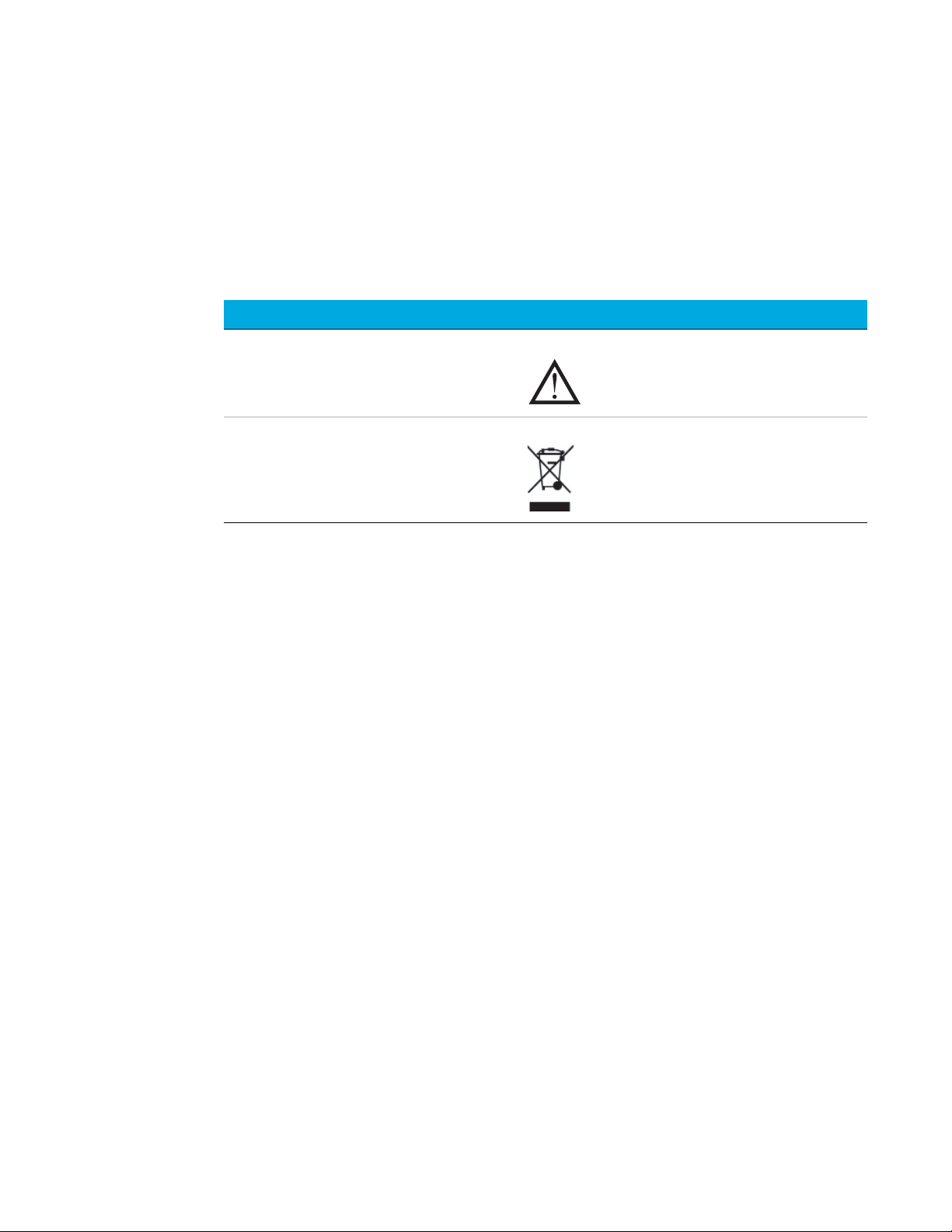
Table 1 Safety symbols
Description Symbol
See accompanying instructions for more information.
Indicates that you must not discard this electrical /
electronic product in domestic household waste.
Quiet Cover MS User Manual 6
Page 7

1Important Safety Warnings
WARNING
WARNING
CAUTION
CAUTION
WARNING
Important Safety Warnings
Important Safety Warnings
Safety cautions and warnings must be observed during all phases of operation, service, and repair
of Quiet Cover MS. Failure to comply with these precautions violates safety standards of design
and Quiet Cover MS’s intended use. Agilent Technologies assumes no liability for the customer’s
failure to comply with these requirements.
A two-person lift is required when removing the Quiet Cover MS from the packaging. Failure to
perform a two person lift may result in personal injury.
Never run the pump without also running Quiet Cover MS.
While running Quiet Cover MS:
• Do not block air flow to the fan.
• Do not set items on top of Quiet Cover MS.
• It is important that the Quiet Cover MS not recirculate hot air. Always position the
Quiet Cover MS where it can draw cool air on all sides.
Be sure to position Quiet Cover MS so that there is plenty of room to allow access to panels and
controls.
In the event of a temperature alarm malfunction or if the alarm has been on for an extended
period of time, the Quiet Cover MS and the pump may be dangerously hot. Check that the
Quiet Cover MS and pump are cool before you touch them.
7 Quiet Cover MS User Manual
Page 8

1Cleaning
Electromagnetic compatibility
Electromagnetic compatibility
This device complies with the requirements of CISPR 11. Operation is subject to the following two
conditions:
• This device may not cause harmful interference.
• This device must accept any interference received, including interference that may cause
If this equipment does cause harmful interference to radio or television reception, which can be
determined by turning the equipment off and on, the user is encouraged to try one or more of the
following measures:
• Relocate the radio or antenna.
• Move the device away from the radio or television.
• Plug the device into a different electrical outlet, so that the device and the radio or television
• Make sure that all peripheral devices are also certified.
• Make sure that appropriate cables are used to connect the device to peripheral equipment.
• Consult your equipment dealer, Agilent Technologies, or an experienced technician for
undesired operation.
are on separate electrical circuits.
assistance.
Cleaning
• Changes or modifications not expressly approved by Agilent Technologies could void the
user’s authority to operate the equipment.
Sound emission certification for Federal Republic of Germany
• Sound pressure – Lp < 70 dB am according to EN 27779:1991.
• Schalldruckpegel – LP < 70 dB am nach EN 27779:1991.
To clean the Quiet Cover MS:
1 Reach under the front of Quiet Cover MS and pull out the oil tray.
2 Wipe out excess oil with a clean, lint-free cloth.
3 Wash the tray with a mild soap solution.
4 Wipe away any spills or other debris from the Quiet Cover MS using a clean, lint-free cloth.
Recycling the Product
For recycling, contact your local Agilent sales office.
Quiet Cover MS User Manual 8
Page 9
1 Parts Identification
NOTE
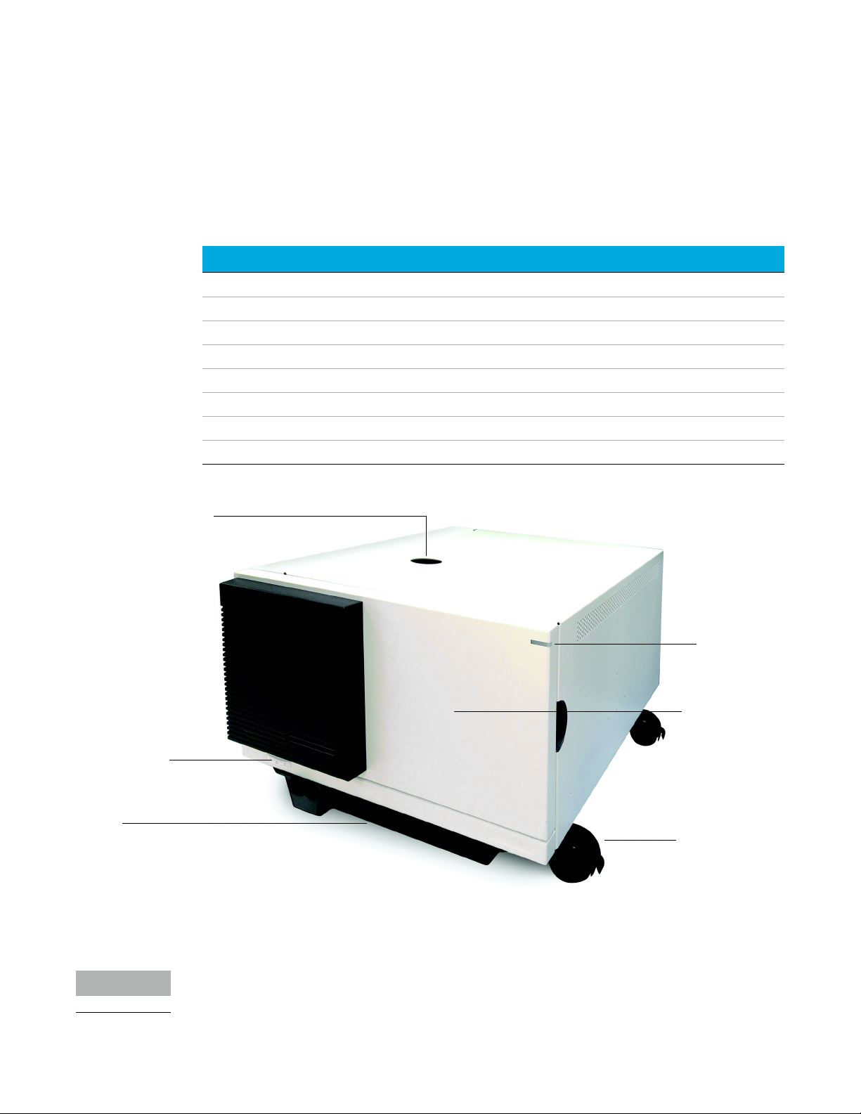
Status light
Locking caster
Power switch
Foreline hose opening
Oil tray
Access door
Parts Identification
Parts Identification
Table 2 lists the contents of the Quiet Cover MS kit. Figure 1 and Figure 2 on page 10 depict the
parts of the Quiet Cover MS.
Table 2 G6011B Quiet Cover MS contents list
Part Quantity Part number
Quiet Cover MS 1 G6011B
Oil tray 1 G6011-40100
Power supply 1 5188-1164
KF40 Trim ring 1 n/a
Quiet Cover MS User Manual 1 G6011-90110
MS40+ Mounting Spacer 4 n/a
MS40S Front Air Duct 1 n/a
MS40S Exhaust Fitting 1 n/a
Figure 1. Quiet Cover MS (front view)
9 Quiet Cover MS User Manual
See Figure 10 on page 21 for a view of the front panel control.
Page 10

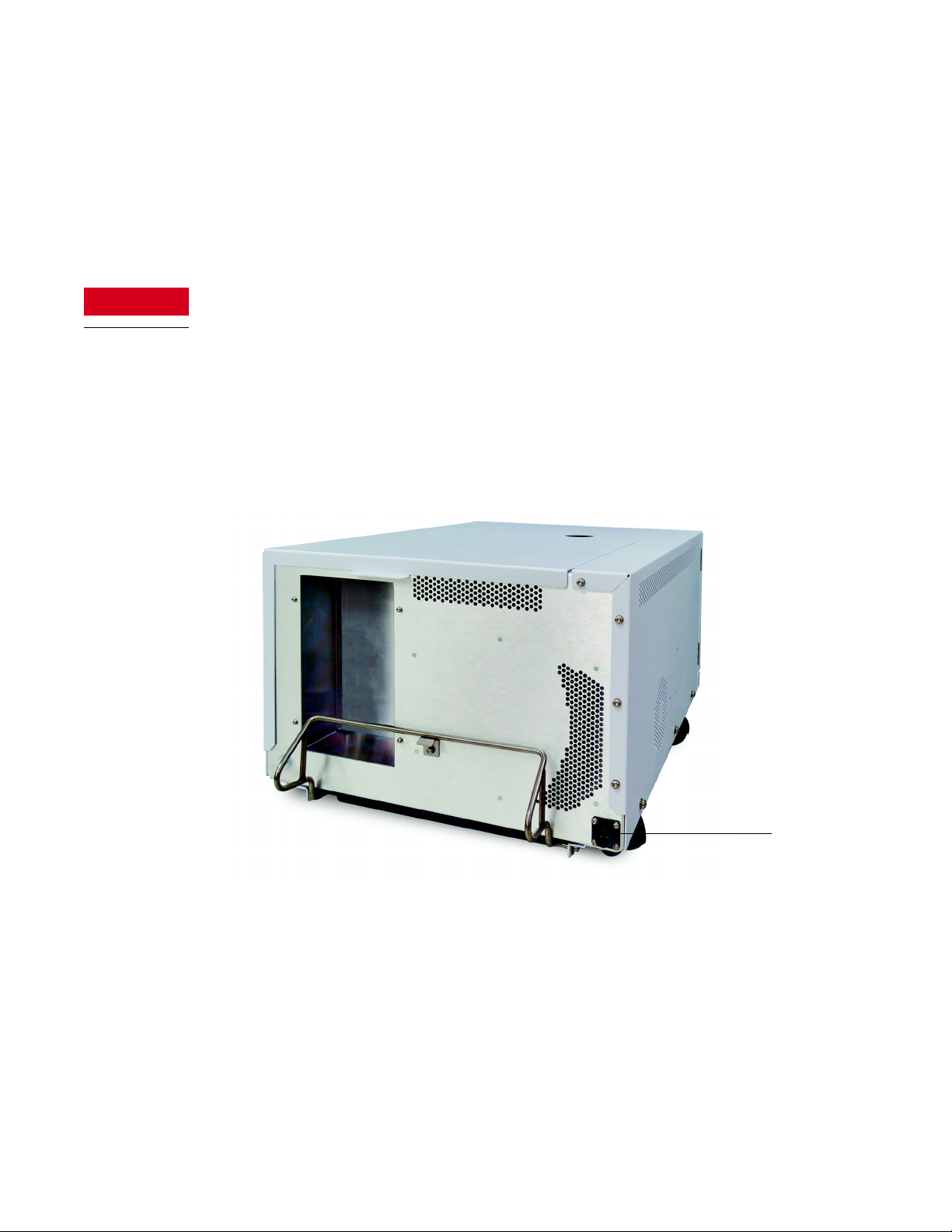
1 Parts Identification
Kickstand
Power connection
Fan Intake
Parts Identification
Figure 2. Quiet Cover MS (rear view) (power supply not shown)
Quiet Cover MS User Manual 10
Page 11

1 Site Preparation
Site Preparation
Site Preparation
Prepare the installation site to meet the criteria in Table 3.
Table 3 Site prep information
Criteria Description
Physical dimensions
Weight 11.3 kg (25 lbs)
Dimensions Kickstand up:
Power supply
AC input voltage 100 to 240 VAC ±10%
DC output voltage +24 V
Output load (max.) 1.25 A
Input frequency 47 to 63 Hz
Power consumption 11 W
Rated current 450 mA
Temperature and humidity ranges
Ambient temperature 5 to 35 °C (41 to 95 °F)
Humidity 15 to 95%
Altitude ≤ 4,600 m (14,950 ft)
68 × 25 × 44 cm (27 × 13.5 × 17.25 inches)
(L × W × H)
11 Quiet Cover MS User Manual
Page 12

Installation
Installing the Oil Tray 13
Accommodating a KF40 Foreline Pump Intake Flange 14
Installing the Rough Pump Inside the Quiet Cover MS 15
Connecting the Power Supply 18
Verifying the Installation 19
This chapter describes how to assemble the Quiet Cover MS and install the rough pump.
Quiet Cover MS User Manual 12
Page 13

2 Installing the Oil Tray
Deep part of tray
Slide in tray
Installing the Oil Tray
Installing the Oil Tray
Your Quiet Cover MS is shipped to you with the oil tray packaged separately. You need to install it
prior to using the Quiet Cover MS.
1 Remove any protective film from the tray.
2 Slide the tray into the bottom of the Quiet Cover MS with the deep part of the tray facing the
front of the Quiet Cover MS. Along the bottom edge of the frame, a pair of rails guides the tray
into place (Figure 3).
Figure 3. Installing the oil tray
Quiet Cover MS User Manual 13
Page 14

2 Accommodating a KF40 Foreline Pump Intake Flange
KF25 Flange ring
Installed KF40 Trim ring
Accommodating a KF40 Foreline Pump Intake Flange
Accommodating a KF40 Foreline Pump Intake
Flange
The G6011B Quiet Cover is configured from the factory to accommodate an MS-40+ vacuum
pump with a KF25 Foreline Pump intake flange.
If you are installing the G6011B Quiet Cover on an MS-40 vacuum pump with a KF25 Foreline
Pump intake flange, skip this procedure.
If you are installing the G6011B Quiet Cover on an MS-40 vacuum pump with a KF40 Foreline
Pump intake flange, follow this procedure to exchange the fitting to accommodate the KF40.
To exchange the fitting:
1 Remove the KF25 Flange, KF25 trim ring, and KF25 insulating foam from the top cover.
2 Install the KF40 Trim ring. See Figure 4.
Quiet Cover MS User Manual 14
Figure 4. Installing the KF40 foreline trim ring
Page 15

2 Installing the Rough Pump Inside the Quiet Cover MS
NOTE
Mounting tabs with
MS-40+ spacers
MS-40S
Elbow fitting
MS-40S
Front air duct
Installing the Rough Pump Inside the Quiet Cover MS
Installing the Rough Pump Inside the Quiet Cover MS
The pump must be disconnected from the LC/MS when placing it inside the Quiet Cover MS.
Configuring the G6011B Quiet Cover for the correct revision of MS-40 vacuum pump:
• MS-40+
• MS-40S (variable speed electrical pump fan)
The G6011B Quiet Cover is configured from the factory to accommodate an MS-40+ vacuum
pump. If this revision of pump is being installed, no changes are required and the installer can
proceed to the next procedure on page 16.
If an MS-40S pump is being installed, complete the procedure below before proceeding to the next
procedure on page 16.
1 Remove the MS-40+ mounting spacers attached to the G6011B floor mounting tabs.
2 Attach the MS-40S Elbow fitting.
3 Use a T10 driver to remove the six M3 screws, and replace the MS-40+ Front Air Duct with the
MS-40S Front Air Duct included inside the accessories box.
Figure 5. Front air duct, elbow fitting, and mounting tabs
Quiet Cover MS User Manual 15
Page 16

2 Installing the Rough Pump Inside the Quiet Cover MS
WARNING
WARNING
Main cover
Door finger
pull
Locking caster
Installing the Rough Pump Inside the Quiet Cover MS
To install the rough pump inside the Quiet Cover MS:
1 Lock the front locking casters to secure the Quiet Cover MS (Figure 6).
Figure 6. Locking casters, top access panels, and main cover
2 To remove the main cover assembly:
a Open the front access door.
b Lift the main cover vertically to detach it from the guide pins.
A two-person lift is required when installing the rough pump into the Quiet Cover MS.
Failure to perform a two person lift may result in personal injury.
The pump may be hot. Use gloves when moving it or wait until it is cool.
Quiet Cover MS User Manual 16
Page 17

2 Installing the Rough Pump Inside the Quiet Cover MS
NOTE
Mounting tabs with
MS-40+ spacers
Motor air duct
Exhaust hose tubing
Power cord
connection
EBox opening
Installing the Rough Pump Inside the Quiet Cover MS
3 Install the rough pump into the Quiet Cover MS. Orient the rough pump support foot into the
front mounting cup inside the Quiet Cover MS and between the Quiet Cover MS mounting tabs
so that the pump oil level window sight glass faces the front access door (Figure 7).
Figure 7. Mounting cup and mounting tabs on the Quiet Cover MS
• The rough pump should fit against the Quiet Cover MS motor air duct when the pump feet are
positioned between the mounting tabs and inside the one mounting cup. A slight gap is
acceptable. If the support feet do not align with the mounting cup and mounting tabs, the
rough pump orientation is incorrect.
• Pump should be slightly touching both the motor air duct and the electrical panel access door.
4 Connect the pump power cord to the rough pump through the EBox opening (Figure 8).
Figure 8. Pump power cord
5 Set the power switch to the On position through the EBox opening (Figure 8 on page 17).
The pump is controlled by the MS and should always be left on.
6 Install the clear PVC exhaust hose included with the quiet cover to the MS40 exhaust port.
Refer to MS40 installation manual for more information.
Quiet Cover MS User Manual 17
Page 18
2 Connecting the Power Supply
WARNING
Connect
power
Connecting the Power Supply
7 Install the main cover assembly. Confirm the cover stud guide pins are aligned properly with
the main chassis assembly.
8 Close the front access door.
9 Connect MS Foreline hose to the pump. Refer to pump documentation or more information.
10 If the Quiet Cover MS is not currently in its operating location, unlock the locking casters,
carefully push the Quiet Cover MS to its operating location, and lock the front locking casters.
Do not attempt to lift the Quiet Cover MS with the rough pump installed. Lifting the
Quiet Cover MS with the rough pump installed may result in personal injury.
Connecting the Power Supply
Connect the power supply to the back of Quiet Cover MS by twisting the ring on the circular
connector of the power cord (Figure 9). Plug the pronged end of the power cable into the wall
outlet.
Quiet Cover MS User Manual 18
Figure 9. Connecting the power supply
Page 19

2 Verifying the Installation
NOTE
NOTE
Verifying the Installation
Verifying the Installation
When the G6011B Quiet Cover is plugged into an external power outlet, the Power Switch (front
lower left-hand corner of the Quiet Cover) will light up orange. This indicates that power is
connected to the Quiet Cover.
To verify that you installed the Quiet Cover MS correctly,
1 Position the power cords so they do not interfere with the kickstand (Figure 2).
2 Lock the casters to avoid unwanted movement of the Quiet Cover MS.
3 Turn the Power Switch to the off position.
4 Plug the G6011B Quiet Cover into an external power outlet. If the instrument is receiving
power, the Power Switch (Figure 1) should light up orange.
5 Turn the Power Switch on. If the instrument is turned on correctly, the Power Switch (Figure 1)
should light up green.
If the ambient temperature is < 35 °C, the temperature alarm and the fan should be off, and
the status indicator should light up green.
If the Quiet Cover internal temperature exceeds 35 °C, the fan should turn on, and the status
light will light up orange. This is the normal operating mode.
In normal operating modes, the status light will be either green or orange, depending on if the fan
is on or not.
Quiet Cover MS User Manual 19
Page 20

Operation
Control Panel and Indicators 21
Handling Temperature Alarms 21
Changing Rough Pump Oil 22
Using the Kickstand 24
To operate Quiet Cover MS, you will need to:
• Understand the controls and indicators on the front panel
• Know how to handle temperature alarms and signals
• Know how to drain oil from the rough pump and oil tray
• Be able to tilt the Quiet Cover MS using the kickstand for draining the oil
Quiet Cover MS User Manual 20
Page 21

3 Control Panel and Indicators
NOTE
Power switch
Status light
Control Panel and Indicators
Control Panel and Indicators
Figure 10 shows the location of the on/off switch and indicators of the Quiet Cover MS control
panel.
Figure 10. Control panel
Handling Temperature Alarms
In normal operation the Quiet Cover MS fan will turn off and on to maintain the temperature set
limits. The status light will be green when the fan is off. The status light will be orange when the
fan is on, but the temperature is still within set limits. Both statuses are normal operating modes.
If the air flow to the Quiet Cover MS is restricted or if the room temperature is above 35 °C (95 °F),
the red status indicator on the front panel lights and the temperature alarm sounds.
When this condition occurs, remove any items from around the Quiet Cover MS that could be
restricting air flow. Check that the fan is turning and that air flow to the Quiet Cover MS is not
restricted.
It is important that the Quiet Cover MS not recirculate hot air. Always position the front end of
the Quiet Cover MS where it can draw cool air.
You cannot turn the alarm off. It will stop when the temperature returns to an acceptable level.
21 Quiet Cover MS User Manual
Page 22

3Changing Rough Pump Oil
NOTE
Oil fill plug
Sight glass
Oil drain plug
Changing Rough Pump Oil
Changing Rough Pump Oil
Periodically, you must change the rough pump oil. The oil tray of the Quiet Cover MS is designed
to collect the oil as it drains from the pump. Please refer to your pump documentation for detailed
information regarding changing your pump oil.
To change the oil:
1 Properly prepare your system for release of primary vacuum.
2 Turn off the rough pump.
3 Turn off the Quiet Cover MS.
4 Unplug the power supply from the Quiet Cover MS.
5 Lock the locking casters to secure the Quiet Cover MS.
6 Open the front access door of the Quiet Cover MS.
7 Tilt the Quiet Cover MS by using the kickstand located at the back of the Quiet Cover MS
(Using the Kickstand on page 24.) This technique is the most efficient way to drain the pump
oil.
8 Be sure the oil tray is securely seated.
The pump sits close to the front of the Quiet Cover MS.
Pull the tray out 1 to 2 inches to avoid oil spillage.
9 Remove the oil drain plug from your rough pump (Figure 11).
Refer to your pump documentation.
Figure 11. View of pump through access door
Quiet Cover MS User Manual 22
Page 23

3Changing Rough Pump Oil
Oil fill plug
Oil drain plug
Changing Rough Pump Oil
10 Reinstall the drain plug when the oil has completely drained.
11 Remove the oil tray and dispose of the oil according to local safety and environmental
guidelines.
12 Return the Quiet Cover MS to its untilted position. See “Using the Kickstand” on page 24.
13 Reinsert the oil tray.
14 Remove the oil fill plug (Figure 12) and refill the pump (Figure 13). Refer to the pump
documentation for more information.
Figure 12. View of pump through access door
Figure 13. Refilling the pump with oil
15 Reinstall the oil fill plug and close the access door.
23 Quiet Cover MS User Manual
Page 24

3 Using the Kickstand
Locking
casters
Kickstand
Retaining clip
Main cover
lift tab
Using the Kickstand
Using the Kickstand
To tilt the Quiet Cover MS:
1 Make sure the Quiet Cover MS is on a level surface.
2 Lock the two locking casters located on the front of the Quiet Cover MS (Figure 14).
Figure 14. Locking casters on the front of the Quiet Cover MS
3 Release the kickstand from the retaining clip (Figure 15).
Figure 15. Releasing the kickstand
Quiet Cover MS User Manual 24
Page 25

3 Using the Kickstand
NOTE
CAUTION
CAUTION
Using the Kickstand
4 Step down on the horizontal bar and lift gently on the back end of the Quiet Cover MS while
Do not lift by the main cover assembly. Use the main cover lift tab.
stepping on the kickstand until the Quiet Cover MS is in its tilted position (Figure 16).
Figure 16. Quiet Cover MS in a tilted position
Be sure that the kickstand’s horizontal bar sits flat on the floor when Quiet Cover MS is tilted.
To return Quiet Cover MS to the untilted position:
1 Grasp the back of the Quiet Cover MS and gently push the Quiet Cover MS forward, off the
kickstand. To avoid dropping it, step on the kickstand as you lower the unit.
Take care when lowering the Quiet Cover MS from the tilted position.
2 Raise the kickstand to its locked position.
3 If necessary, unlock the front locking casters, push the Quiet Cover MS back to its operating
location, and lock the front locking casters to secure the Quiet Cover MS.
25 Quiet Cover MS User Manual
Page 26

Troubleshooting
Table 4 describes solutions to problems that may occur with Quiet Cover MS. If your problem is
not listed or the solution listed does not work, consult your pump documentation or contact your
Agilent service representative.
Table 4 Problems and solutions
Problem Solution
Pump does not fit in Quiet Cover MS. Check for proper orientation of the pump and configuration of mounting spacers. See Installing the
Quiet Cover MS does not turn on. Check that the power supply is plugged securely into both Quiet Cover MS and the wall outlet. If it is,
Temperature alarm does not turn off. Remove the Quiet Cover MS main cover. Ensure that adequate cool air is available to the Quiet Cover
Quiet Cover MS poorly muffles the sound of the
pump.
The rough pump oil does not drain completely. Be sure the kickstand is down, with the bar sitting flat on the floor.
Green LED does not light. Check that power is supplied to Quiet Cover MS and the power switch is on.
Fan does not turn. The Quiet Cover MS fan will be off while the status light is Green. During normal operation, the
The temperature alarm does not sound even
though the room temperature is above 35 °C
(95 °F) and the red over-temperature LED is lit.
The red over-temperature LED is not lit even
though the room temperature is above 35 °C
(95 °F) and the alarm is sounding.
The temperature alarm is not sounding and the
red over-temperature LED is not lit even though
the room temperature is above 35 °C (95 °F).
Rough Pump Inside the Quiet Cover MS on page 15. Call your Agilent service representative if the
orientation and configuration are correct.
Confirm the correct Quiet Cover configuration depending on whether you are installing an MS40+ or
MS40S.
call your Agilent service representative. Do not continue to use your rough pump in the Quiet Cover
MS.
MS. Call your Agilent service representative if the lab temperature is within specifications.
Ensure that the main cover is properly fitted onto the Quiet Cover MS.
Confirm that the front access door is fully closed.
If so, refer to the rough pump documentation for more information.
If it is, call your Agilent service representative.
Quiet Cover MS is designed to use the pump's fans to cool the pump. When additional cooling is
required, the Quiet Cover MS fan will turn on and the status light will turn orange. If the fan is NOT on
when the status light is orange or red, call your Agilent service representative. Do not continue to use
your rough pump in the Quiet Cover MS.
Check that power is supplied to Quiet Cover MS and the power switch is on. If it is, call your Agilent
service representative. Do not continue to use your rough pump in the Quiet Cover MS, the alarm
may have failed.
Check that power is supplied to Quiet Cover MS and the power switch is on. If it is, call your Agilent
service representative. Do not continue to use your rough pump in the Quiet Cover MS, the LED may
have failed.
Check that power is supplied to Quiet Cover MS and the power switch is on. If it is, call your Agilent
service representative. Do not continue to use your rough pump in the Quiet Cover MS, the
thermostat may have failed.
The Service Manual (part number G6011-90120) contains part replacement information
(procedures performed by Agilent service representatives). Visit www.agilent.com/chem to
download a copy of the Service Manual and look for any other current information.
Quiet Cover MS User Manual 26
Page 27

www.agilent.com
Agilent Technologies, Inc. 2020
Second edition, April 2020
*G6011-90110*
G6011-90110
 Loading...