

Page 1

1
application
HP E8491B IEEE-1394-to-VXI
H
HP Application Note
Increasing Test System Throughput
Page 2

Appendix I. . . . . . . . . . . . . . . . . . . . . . . . . . . . 13
Theoretical Performance . . . . . . . . . . . . . . . . . . 13
Performance Factors . . . . . . . . . . . . . . . . . . . . . 13
VXI Contribution. . . . . . . . . . . . . . . . . . . . . . . . . 14
Appendix II . . . . . . . . . . . . . . . . . . . . . . . . . . . 15
HP E8491B Details . . . . . . . . . . . . . . . . . . . . . . . 15
Features of the IEEE 1394 Bus . . . . . . . . . . . . . 16
Other Advantages . . . . . . . . . . . . . . . . . . . . . . . . 16
Table of Contents
2
Part I:
Measuring Real Test I/O Throughput . . . . . . . . 3
Introduction . . . . . . . . . . . . . . . . . . . . . . . . . . . . . 3
System Throughput Benchmarks. . . . . . . . . . . . . 3
HP Innovations to FireWire Technology . . . . . . . 3
Test Cases . . . . . . . . . . . . . . . . . . . . . . . . . . . . . . . 4
Small Block Measurements. . . . . . . . . . . . . . . . . . 4
High Channel Count . . . . . . . . . . . . . . . . . . . . . . . 5
Functional Test Peek & Poke . . . . . . . . . . . . . . . . 5
Functional Test Scanning . . . . . . . . . . . . . . . . . . . 5
Summary . . . . . . . . . . . . . . . . . . . . . . . . . . . . . . . . 6
Part II:
Understanding VXI Slot 0 I/O Benchmarking . 7
Benchmark . . . . . . . . . . . . . . . . . . . . . . . . . . . . . . 7
Fundamentals . . . . . . . . . . . . . . . . . . . . . . . . . . . . 7
Configure. . . . . . . . . . . . . . . . . . . . . . . . . . . . . . . . 7
Sample or Scan . . . . . . . . . . . . . . . . . . . . . . . . . . . 7
Transfer. . . . . . . . . . . . . . . . . . . . . . . . . . . . . . . . . 7
System Throughput . . . . . . . . . . . . . . . . . . . . . . . 8
Controller Configurations . . . . . . . . . . . . . . . . . . . 9
GPIB . . . . . . . . . . . . . . . . . . . . . . . . . . . . . . . . . . . 9
FireWire. . . . . . . . . . . . . . . . . . . . . . . . . . . . . . . . 10
MXI . . . . . . . . . . . . . . . . . . . . . . . . . . . . . . . . . . . 11
Embedded VXI Controller . . . . . . . . . . . . . . . . . 12
Conclusion . . . . . . . . . . . . . . . . . . . . . . . . . . . 12
Page 3

System Throughput Benchmarks
Getting a true objective measurement of
throughput can be difficult. Published
specifications that measure only part of the test
throughput equation don’t tell a complete story.
In throughput testing, the speed of the interface
sending a command to the target device is very
often the only consideration. But by merely
testing the throughput of one element of a real
test, false conclusions can result: other elements
of the test that are critical to throughput are often
ignored, and opportunities to improve throughput
are often missed.
In the real world of test and measurement, the
time to send a command to a working device, take
a reading, and return it for display or output is a
more complete test for system throughput. So
while the test of the technology with infinitely fast
instruments is addressed in this document (see
Appendix I and II), the real measure of I/O
throughput is the system throughput benchmark.
The test cases described in the following pages
illustrate the throughput benchmark for actual
test measurements.
HP Innovations to FireWire Technology
FireWire transmits "packets" of data in big blocks,
much like a local area network (LAN). Because of
the serial nature of data transmission, first-byte
latency—or the time it takes to transfer the first
byte after the command to initiate is given—is an
issue relevant to throughput. Each data packet
carries this overhead of latency, contributing to
the total throughput elapsed time. If each packet
contains one read/write instruction like the typical
GPIB controller, the overhead results in slow
throughput.
The unique big-block aspects of FireWire
technology allow multiple transactions per packet.
This reduces the impact of first-byte latency:
more data can be carried by a given packet,
leading to decreased packet count. HP engineers
developed additional, higher level protocols, and
optimized bit- and byte-ordering, data
transmission, and error detection and correction
of the bit stream. These modifications
contributed to dramatic improvements in real
throughput of IEEE-1394 for test and
measurement applications.
Part I: Measuring Real Test I/O Throughput
3
Introduction
IEEE-1394 ("FireWire") technology is an open,
scalable, flexible, plug-and-play, low-cost serial
interface that is being widely adopted in digital
consumer products and personal computers.
This high-speed serial bus has prompted many
test departments to determine how FireWire can
be used to connect instruments to computers for
test control. Test environments are discovering
that FireWire is ideally suited to test and
measurement applications, allowing significant
reductions in the cost of test.
By moving data faster with large data block
transfers, test time—and consequently the cost
of test—is reduced. Other cost reductions are
achieved in part because serial data transfer
allows the use of a simplified cable design: the
IEEE-1394 high-speed serial bus uses a thin,
flexible, inexpensive cable to provide a fast, easy
connection between computers and external
peripherals. Another cost reduction comes from
simplification of the electronics: the transmitters
and receivers in the standard chip set handle
addressing, initialization, arbitration and protocols,
keeping the cost of IEEE-1394 technology low.
The HP E8491B is Hewlett-Packard’s
implementation of FireWire technology for test
and measurement applications. This IEEE-1394
PC-Link to the VXI interface ships as a C-size,
1-slot, message-based VXI module. The HP
implementation introduces a variety of advantages
as a Slot 0 control solution in the VXI market:
• It is capable of handling the Resource Manager
and Slot 0 responsibilities.
• It can transfer data blocks greater than
64 kilobytes at 14 megabytes per second,
five times faster than its predecessor.
• It eases configuration with the automatic
recognition feature called "hot-plugging,"
which allows the host system to automatically
recognize an IEEE-1394-based device without
powering down the PC.
• It’s scalable, supporting up to 16 mainframes
using daisy chain or star configurations.
• Its data block transfer capability increases
throughput performance well beyond that of
GPIB at a much lower price than MXI, with
results that match embedded solutions.
In terms of architecture, price and speed, FireWire
and embedded solutions are quickly becoming the
dominant choices in Slot 0 control.
Page 4

4
Test Cases
HP has benchmarked the typical classes of
measurement, from sending the command to
setting up the instrument, to taking the
measurement itself, to the storage or display of
measurements. The benchmarks use typical
instruments to perform the kinds of tests
commonly seen in data acquisition and functional
test applications. The benchmarks involve
configuring real instruments, taking a sample, and
transferring the sample. The Slot 0 controllers are
the HP E8491B FireWire Card, the HP E1406B
GPIB Card, the NI VXI-PCI8015 MXI-2 Card and
the HP E6235A Embedded 200 MHz PC. A 200
MHz HP Kayak XU PC was the external PC. The
programming language used for all the cases was
C++. The operating system used by the
computers was Microsoft
®
Windows NT®.
Small Block Measurements
The first benchmark is for a register-based data
acquisition system sampling various waveforms.
In this test, the test system configures a
HP E1563A digitizer to sample waveforms in
1K, 4K, 8K, 16K and 1M sample sizes. Then the
system transfers the data.
The most interesting of these benchmarks involves
smaller block transfers of 1K, as shown in Chart 1.
IEEE-1394 technology is noted for its throughput
on large blocks; in this benchmark, small block
transfers were also very cost-effective. Actual
measurements for 1K, 8K, 16K and 1M are
available on the HP test and measurement web
site, along with a complete set of benchmark
results. The site is located at
http://www.tmo.hp.com/tmo/techinfo/English/
EFT_ Benchmarks_FireWire.html.
In an application such as antenna test, where
speeds faster than GPIB would improve test time,
a HP E8491B FireWire connection provides a
4X improvement in performance. Yet, this
improvement costs only 10 percent more than
GPIB. Note that MXI-2 provides only a marginal
improvement in throughput over the HP E8491B
at nearly twice the price.
Also note the throughput at a sample size of
8K (Chart 2). The efficiency of the IEEE-1394
technology begins to match that of MXI-2 and
embedded controllers. For a wide variety of
applications, the HP E8491B is the most costeffective solution, even when transferring
relatively small blocks of data.
Chart 1
Chart 2
1K Sample from E1563A
% of Embedded
%
100
80
60
40
20
0
E8491B GPIB
8K Sample from E1563A
% of Embedded
%
100
80
60
40
20
0
E8491B MXI2
GPIB
MXI2
Page 5

5
High Channel Count
Charts 3 and 4 show results of another solution
where the IEEE-1394 technology provides
increased throughput at a lower cost in a registerbased data acquisition system requiring a large
number of channels and continuous data
acquisition. This solution uses the direct registerbased protocol that communicates at a lower level
than message-based devices.
In this test, a system scans with three E1413C
64-Channel Scanning A/D Converters, a
configuration that provides the volume of channels
required by many of today’s manufacturing lines.
The HP E1406A GPIB module does not transfer
quickly enough to support multiple HP E1413Cs,
whereas IEEE-1394, MXI-2 and embedded PC all
support the configuration. These three options,
while close in throughput, are widely divergent in
price.
The HP E8491B-based solution is the value leader,
providing virtually the same performance as an
embedded PC at a fraction of the cost. The
HP E8491B-based solution is actually faster than
MXI-2 in this application.
Functional Test Peek & Poke
Chart 5 demonstrates the results of "peek and
poke" measurement times in functional test
applications. This test simulates worst-case
results for the IEEE-1394 technology. In this test,
an HP E1330B Digital I/O inputs or outputs a
control signal; a HP E8460A Multiplexer opens
one switch and closes another; a HP E1411B DMM
changes function and range, then takes one
reading. The HP E8491B provides the low cost
solution with a 40 percent improvement over
GPIB. For high speed requirements, the
embedded solution provides an open architecture
with a smaller footprint for manufacturing
applications.
Chart 3
Chart 5
Chart 4
64 Readings @ 100 kHz Rate
% of Embedded
%
120
100
80
60
40
20
0
E8491B GPIB
50K Readings @ 100 kHz Rate
% of Embedded
%
100
80
60
MXI2
40
20
0
E8491B MXI2
GPIB
Register Based Electronic Functional Test
% of Embedded
%
150
100
50
0
E8491B GPIB
MXI2
Page 6

Summary
IEEE-1394 technology presents an opportunity
for a significant breakthrough in test throughput.
Hewlett-Packard brings that opportunity to
market with the HP E8491B FireWire Slot 0
controller, which simplifies configuration and
reduces the cost of test.
The methods for benchmarking the HP E8491B
provide a true, objective view of the real-world
throughput of an actual test system. The test
systems used for benchmarking represent a crosssection of application architectures common to
today’s manufacturing test environments.
The results:
• While the IEEE-1394 technology posted
predictable competitive throughput numbers for
large-block applications, the HP E8491B
implementation also proved cost effective in
small-block applications.
• For tests involving setup and return of small
data packets only, the interface is largely
irrelevant to throughput, but note that the
IEEE-1394 FireWire technology exceeds GPIB
in throughput at about the same price.
• For tests involving a mixture of large and
small packets, IEEE-1394 FireWire is the
value leader in low cost solutions, far
exceeding GPIB in performance. At the direct
connection to the backplane, the embedded
solution provides open, integrated
architecture and a smaller footprint.
The new HP E8491B PC-Link-to-VXI data block
transfer capability increases throughput
performance well beyond that of GPIB at a price
that is far more attractive than MXI-2. In terms of
architecture, price and speed, FireWire and
embedded solutions are quickly becoming the
dominant choices in Slot 0 control.
6
Functional Test Scanning
This case shows the performance of the various
solutions in an application that is particularly
suited for a system based on the HP E8491B.
This system allows the HP E1411B DMM to
configure the HP E8460A Multiplexer as a
scanning multimeter. The voltmeter commands
will automatically control the switch cards that
are assigned to it. This greatly simplifies
programming and accelerates instrument
operation. This is particularly useful to
applications where multiple units are involved,
such as cable and battery test.
Since HP-generated drivers produce fewer
packets, the cumulative time to process packets is
reduced, as is the cumulative first-byte latency of
a test. Data transfers also take advantage of the
large-block transfer capability of IEEE-1394
technology, so the HP E8491B interface shows
numbers that are very competitive with other
alternatives in this test class.
Chart 6
Register Based Electronic Functional Test
% of Embedded
%
150
100
50
0
E8491B GPIB
MXI2
Page 7

• Random Reads/Writes
VXI also provides another, faster type of
instrument: register-based devices. Registerbased devices communicate at a lower, more
basic level than message-based devices, so
they can attain greater transfer speeds than
message-based instruments. Registers are
high-speed memory locations that interface
directly to an instrument’s on-board control
logic with reads and writes using binary
information. Each read or write can directly
affect the programming state of the device,
with no interpretation required. A read/write
operation sends simple one-, two- or four-byte
data across the VXI bus to non-sequential
registers in VXI shared memory or an
instrument register set.
• Block Transfers
The best example of this is an instrument
with a FIFO buffer for data storage. The
instrument converts a measurement to its
binary equivalent and stores the values to its
FIFO. The VXI controller moves this block of
data from the FIFO to its local memory. This
operation is called the block data transfer.
There is the overhead of setting up each transfer.
For that reason the size of the block is critical to
the performance enhancement that IEEE-1394
controllers can provide. The use of shared
memory and FIFO buffers enable the large-packet
size that makes the system faster and reduces the
cost of test. The bigger the block due to a large
amount of data or a complicated setup command,
the smaller percentage the overhead contributes
to overall throughput.
Sample or Scan
During this period the instrument matches the
configuration it received and takes action.
This period is instrument-dependent and is
independent of the interface being used. The
width (one, two, or four bytes) of the sample or
scan, and their location in the program, vary
among instruments and can affect throughput.
Transfer
At this stage, the system has executed the
command and is ready to transfer the data.
The transfer period is the time it takes to move
the data from the device to storage, or to another
location for display. Once the instrument is ready
to transmit the packet, throughput depends on
the performance of the interface.
Part II: Understanding VXI Slot 0 I/O Benchmarking
7
Benchmark
HP benchmark numbers indicate that the HP
E8491B with FireWire technology has the
potential to be the dominant solution in Slot 0
control. This section discusses the elements of
the benchmark test and proves the veracity of the
results achieved by HP.
Fundamentals
The benchmark measures the time it takes to send
a command across the interface and backplane to
an instrument, and receive the data back. Three
steps are involved: configure, sample or scan, and
data transfer.
• The configure period measures the time
required to initiate a command and send it to an
instrument.
• The sample or scan period measures the total
time required for the instrument to match the
command configuration and act on the
command it received. Note that this time is
instrument-dependent, and is independent of
the interface being used.
• The transfer period measures the time when
the instrument is reporting on the data it
collected from the device under test (DUT).
Configure
The characteristics of the configure period are
determined by the communication method of the
instrument, either word serial protocol, random
reads/writes, or block transfer.
• VXI Word Serial Protocol
Message-based devices communicate with
each other using a standardized procedure
known as "word serial protocol." This
asynchronous protocol defines the handshake
necessary to move commands and data
between devices. It provides a reliable,
standardized way to communicate with
devices, but at the cost of lower throughput.
This is because transferring each byte of a
command string requires a minimum of three
16-bit data accesses. Also, most messagebased device command strings are based on
long human-readable ASCII commands such as
IEEE-488.2 or SCPI commands. So for a
communication cycle of a small data packet,
the interface throughput is not significant to
the throughput of a VXI word serial operation.
Page 8

System Throughput
System performance depends on the components
that make up the system. Each component
contributes the time of its operation to the total
time of a cycle. Drivers that take advantage of the
inherent characteristics of IEEE-1394 technology
can package data to greatly improve performance.
Once the driver is optimized for throughput,
opportunities that arise on the backplane stretch
the technology for performance enhancements.
Together, these multiple enhancements, with their
different contributions, can more efficiently fill the
data bus. This makes for higher overall system
throughput, so a system throughput benchmark is
a more complete measure of performance.
8
With the three areas of focus established, the next
consideration is the test. A true "apples to apples"
comparison is usually achieved by standardizing
the devices and simplifying the test. There is no
danger in standardizing the devices, but
simplifying the test can lead to false conclusions.
To reduce that risk, the HP benchmark tests not
only the throughput of the communication
protocols, but also the system throughput.
Figure 1. Controller Configurations
Page 9

GPIB
This method of connection uses the same
application software and drivers used to program
instruments in the rack-and-stack environment.
Using GPIB, the computer transmits through the
GPIB Interface card across a heavy GPIB cable to
a command module in Slot 0 of the VXI
mainframe. This VXI module translates data to
and from the VXI word serial protocol. Figure 2
illustrates the method. The computer transmits a
string to a VXI instrument. The command module
determines the device address and sends the
string to the appropriate instrument using word
serial protocol.
9
Controller Configurations
Four basic interface methods (Figure 1) span the
range of configurations for connecting to VXI.
The traditional method is the GPIB connection
between the computer and the VXI Slot 0 card. A
card in the controller connects to the GPIB Slot 0
card by a GPIB cable. The IEEE-1394 card fits in
Slot 0 of the VXI mainframe with a PCI card in the
computer connected by the IEEE-1394 cable. The
MXI method connects the controller to the VXI
bus through a multi-wire cable much like GPIB.
The most direct connection is the embedded
controller that fits in Slot 0 of the VXI mainframe
and connects directly to the VXIbus.
Figure 2. GPIB – VXI Architecture
Page 10

FireWire
The HP E8491B controller configuration consists
of a VXI Slot 0 controller, a thin, flexible serial
cable, and an expansion board that plugs into the
PCI expansion slot of a computer. Figure 3
illustrates the communication method. Note that
the remote computer transmits a string to a VXI
instrument. Data is serialized at the PCI
expansion card and IEEE-1394 data packets are
created. Packets travel across the cable and are
made into parallel data in the HP E8491B
interface. The HP E8491B converts the packet
10
In message-based instruments, the command
module only needs to translate the GPIB protocol
to word serial protocol. For register-based
devices, the command module must interpret the
string and convert it into register reads/writes that
are appropriate for the device.
This additional transaction for register-based
instruments makes GPIB a much slower controller
method than the others. VXI systems using GPIB
will never reach the maximum throughput
because of the translations and interpretation of
the relatively slow command module.
Figure 3. IEEE-1394 Architecture
Page 11

11
data to either word serial protocol or random
reads/writes, determines the device address,
and sends the string down the backplane to the
appropriate instrument.
Because of the nature of the serial bus, the
IEEE-1394 protocol must turn data into packets,
arbitrate for the bus, and gain VXI memory
access. This creates the first-byte latency for the
IEEE-1394 protocol. To minimize the impact of
first-byte latency, the HP E8491B solution
optimizes the PCI card, includes drivers to pass a
macro of commands rather than individual
commands, and turns interrupts off.
MXI
The MXI system is illustrated in Figure 4.
It connects the controller bus to the VXI bus in
much the same way as the previous methods.
An on-board card in the computer connects
through a large cable to the special MXI Slot 0
card. Data moves in parallel transfers between
the buses by directly converting the data cycles
in hardware. No time is spent creating packets or
command strings.
MXI interface performance is highly dependent
on the expansion bus and microprocessor in
the computer. The PCI bus provides 32-bit
bi-directional transfers with throughput that is
well in excess of the ISA bus 16-bit transfer. The
faster the microprocessor, the faster the overhead
associated with random reads and writes, and the
faster word serial transfers are processed.
Figure 4. MXI-2 Architecture
Page 12
Conclusion
For most manufacturers, there is a dire need to
test faster and reduce the cost of test. FireWire
technology offers an opportunity to do just that.
The HP E8491B uses the inherent characteristics
of IEEE-1394 technology to improve throughput
between instrument and controller for test and
measurement applications. With the best
price/performance ratio of any VXI-based
instrument control solution, the HP E8491B has
the potential to become the dominant Slot 0
solution on the market. It is part of HP’s ongoing
strategy to bring new innovations to market that
advance the state-of-the-art in open systems
architectures and VXI technologies, with complete
solutions that are easy to use, easy to buy and
easy to afford.
12
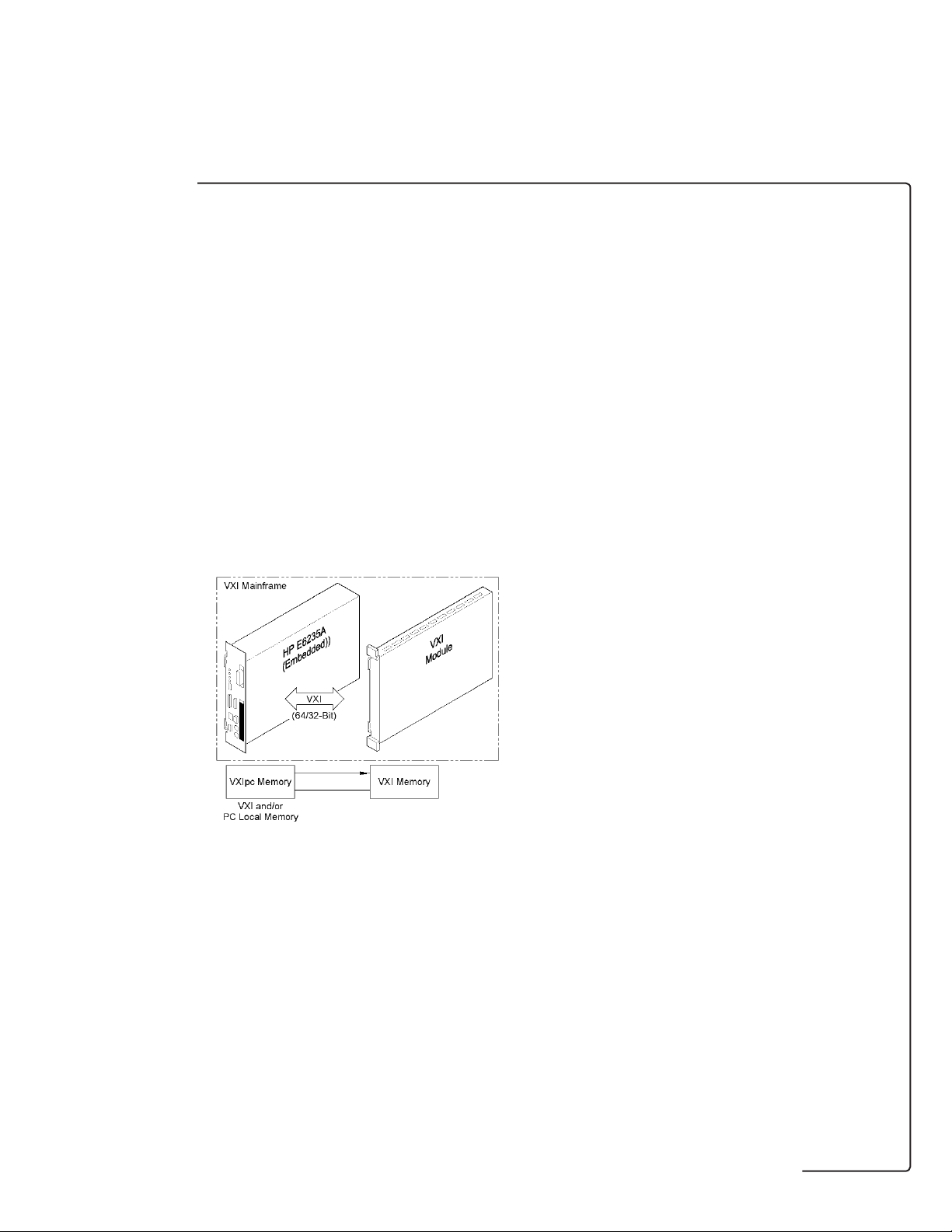
Embedded VXI Controller
In the embedded VXI controller configuration
shown in Figure 5, the controller is physically
located in Slot 0 of the VXI chassis. This
configuration connects the controller directly to
the VXI bus, allowing the controller to access all
signals on the backplane. There is lower overhead
for transactions since software translations are
eliminated due to the direct read/write of the
registers for both message- and register-based
instruments. Binary data is transferred in parallel
to and from the instrument at high speed.
The embedded VXI controller is built on a VXI
card format. It is a specialized type of controller
based on the PC specifications. It is the smallest
connection, giving it a footprint advantage over
other methods. Direct connection to VXIbus also
provides a throughput advantage.
Figure 5. Embedded Controller Architecture
Page 13

Performance Factors
Theoretical maximum throughput and first-byte
latency do not take into consideration other
factors that impact the performance of the
system. One of those factors is context switching.
The context-switching period is the time a
multitasking operating system uses to stop
running one process and start running another.
This period must be added to the total
throughput. Related activities such as interrupts
and I/O drivers also make a contribution to the
throughput totals. Architecture of the operating
system dictates the duration of many of these
activities, but variations between operating
systems are very small.
The environment itself will make a contribution.
Applications developed in a compiled environment
make less of an impact on transfer speeds than
those developed in an interpreted environment.
Interpreted environments must analyze each
statement in the program each time it is executed.
In compiled environments, analysis is done at the
conversion of a program to machine code.
Doing the analysis at the time of compiling in
conjunction with faster-executing machine code
allow programs from compiled environments to
execute faster than programs from interpreted
environments.
The final factor affecting system performance is
the speed of the target device. The speed of the
measurement, the width of the reading in bytes
and the location of the measurement in the test
programs combine to affect the overall
throughput.
Appendix I
13
Theoretical Performance
It is useful to look at theoretical and infinitely fast
instruments to see why system throughput is the
practical way to evaluate performance.
Theoretical maximum transfer rate shown in
Table 1. describes the data rate to and from an
infinitely fast instrument. The first-byte latency
is the elapsed time from the beginning of the
instruction to transfer the first byte to the actual
transfer across the link.
Measuring maximum transfer rate and first-byte
latency alone do not provide a representative
overall transfer rate for a system because they
only measure the time to the start of an
instruction. This leaves out, among other things,
the time to transfer the sample.
In the 8K waveform shown in Table 2. scanning
benchmark, the transfer of the sample takes more
time than the configure step. As noted, the
sample rate is instrument-dependent, but the
transfer rate is certainly dependent on the
interface. Any useful benchmark must include
the time of the transfer of a reading.
Table 1. Theoretical Performance
Table 2. Actual System Performance
Embedded GPIB MXI-2 IEEE-1394
Max Transfer Rate 80 Mbytes/s 1 Mbytes/s 33 Mbytes/s 43 Mbytes/s
(VME64)
First-Byte Latency 80 ns 10µs 1 µs 5 µs
Time In MS Embedded GPIB MXI-2 IEEE-1394
Configure 0.21 29.17 0.18 3.55
Sample 117.78 119.57 117.35 117.59
Transfer 4.11 490.27 12.65 5.76
Total 122.10 639.01 130.18 126.90
Page 14

14
VXI Contribution
The VXIbus backplane has a theoretical data
transfer limit of 40 Mbytes per second. Normally,
the backplane will not be a bottleneck for a data
transfer. The not-so-obvious advantage of the
VXIbus is its potential for distributed intelligence,
which leads to increased system throughput.
Because of its VMEbus background, VXIbus can
deal with multiple microprocessors on the
backplane existing within a shared memory
architecture. Multiple levels of priority allow
critical processes to interrupt and use resources
only when they are required. This capability,
when combined with creative use of drivers,
created the opportunity to dramatically improve
throughput and the price/performance impact of
the HP E8491B.
Page 15

Table 1 shows that moving blocks of data with the
HP E8491B is a more efficient way to transfer
data than using single read/writes. When an
application requires that several bytes of data be
sent to separate locations, standard VISA I/O
libraries do not provide a mechanism for
combining these operations into a single block
operation. Macro technology created by HP R&D
Engineers provides this mechanism.
By packing several write commands into a macro
rather than sending individual writes, considerable
improvement in throughput is achieved. Table 2
shows the advantages of this alternative by
showing macro speeds compared to individual
read/writes. The times indicate that the macros
are a higher performance alternative to individual
read/writes.
Appendix II
15
HP E8491B Details
The interface improves data transfer throughput
where data can be sent in large blocks. This is
particularly convenient for data acquisition
instruments. These instruments can take
advantage of the HP E8491B’s tremendous
throughput to transfer information from the
instrument to computer without saturating the
bus.
For purposes of comparison, Table 1 shows the
performance of the HP E8491B with an infinitely
fast instrument. This benchmark shows the time
in microseconds (µs) it takes for the computer to
prepare and send a command over the backplane.
This time is then computed into a rate expressed
in kilobytes per second.
Commands Transfer Type Transfer Size (Bytes) Time (µs) Rate (kBytes/s)
ViPeek16 16 bit read 2 130 15
ViMoveIn16 16 bit read 16 170 94
" 16 bit read 4096 1110 3690
" 16 bit read 122880 12300 9760
viMoveIn32 32 bit read 122880 8390 14300
iblockmovex64 read
64 bit read 122880 8330 14400
ViSend Word Serial Message 128 1600 20
# Writes ViPoke16 (µs) Macro (µs) Macro Advantage
(Individual Write) (Combined Writes)
1 200 240 -40
2 400 250 150
3 600 250 350
4 790 260 530
5 990 270 720
6 1200 280 920
16 3200 390 2810
Table 2. Comparison of individual vs. macro read/write
performance
Table 1. Shorted Benchmarks
Page 16

16
Features of the IEEE 1394 Bus
The following features of the IEEE-1394 bus apply
to all bus applications including VXI systems.
• Daisy chain or branching configurations are
allowed. There can be no closed loops (i.e. more
than one connection between any two devices).
• Up to 63 devices (including 16 HP E8491Bs)
are allowed per bus segment. One host
adapter represents one bus segment.
• There is a maximum of 16 hops* between any
two devices. The bus cable length cannot
exceed 72 meters between any two devices.
• Live/hot connections. A VXI mainframe
anywhere in the configuration can be turned
on/off at any time without affecting the other
mainframes. The IEEE-1394 bus automatically
reconfigures itself any time a VXI mainframe
(or other device) is added or removed.
*A hop is an IEEE-1394 cable link between nodes.
Other Advantages
Other advantages of an IEEE-1394 VXI Slot 0
module are built-in support and more flexible
cabling.
Both Intel and Microsoft have endorsed
IEEE-1394 and use it as one of two serial buses as
part of the sealed PC concept. Microsoft has builtin support for IEEE-1394 in Windows 98
®
and the
upcoming Windows 2000
®
.
Cabling is another benefit for instrumentation:
flexible cable and bridging structure with
IEEE-1394 allows instruments and controllers to
be placed in desired locations instead of being
limited by cable length and flexibility.
Technical data is subject to change.
Microsoft, Windows 98, Windows NT and
Windows 2000 are U.S. registered trademarks
of Microsoft Corp. All other tradenames and
trademarks are the property of their respective
owners.
© Hewlett-Packard Company 1999
Printed in the U.S.A. 10/99
5968-7237E
For more information about Agilent Technologies test and
measurement products, applications, services, and for a
current sales office listing, visit our web site:
http://www.agilent-tech.com/go/tmdir
You can also contact one of the following centers and ask
for a test and measurement sales representative.
United States:
Agilent Technologies
Test and Measurement Call Center
P.O. Box 4026
Englewood, CO 80155-4026
(tel) 1 800 452 4844
Canada:
Agilent Technologies Canada Inc.
5150 Spectrum Way
Mississauga, Ontario
L4W 5G1
(tel) 1 877 894 4414
Europe:
Agilent Technologies
European Marketing Organisation
P.O. Box 999
1180 AZ Amstelveen
The Netherlands
(tel) (31 20) 547 9999
Japan:
Agilent Technologies Japan Ltd.
Measurement Assistance Center
9-1, Takakura-Cho, Hachioji-Shi,
Tokyo 192-8510, Japan
(tel) (81) 426 56 7832
(fax) (81) 426 56 7840
Latin America:
Agilent Technologies
Latin American Region Headquarters
5200 Blue Lagoon Drive, Suite #950
Miami, Florida 33126
U.S.A.
(tel) (305) 267 4245
(fax) (305) 267 4286
Australia/New Zealand:
Agilent Technologies Australia Pty Ltd
347 Burwood Highway
Forest Hill, Victoria 3131
(tel) 1-800 629 485 (Australia)
(fax) (61 3) 9272 0749
(tel) 0 800 738 378 (New Zealand)
(fax) (64 4) 802 6881
Asia Pacific:
Agilent Technologies
19/F, Cityplaza One, 1111 King’s Road,
Taikoo Shing, Hong Kong, SAR
(tel) (852) 2599 7889
(fax) (852) 2506 9233
H
 Loading...