

Page 1

Service Guide
E8362B, E8363B, E8364B
Agilent Technologies
PNA Series
Microwave Network Analyzers
Part Number E8364-90026
Printed in USA
May 20, 2011
Supersedes: March 29, 2011
© Agilent Technologies, Inc. 2002–2011
Page 2

WARRANTY STATEMENT
THE MATERIAL CONTAINED IN THIS DOCUMENT IS PROVIDED “AS IS,” AND IS SUBJECT
TO BEING CHANGED, WITHOUT NOTICE, IN FUTURE EDITIONS. FURTHER, TO THE
MAXIMUM EXTENT PERMITTED BY APPLICABLE LAW, AGILENT DISCLAIMS ALL
WARRANTIES, EITHER EXPRESS OR IMPLIED WITH REGARD TO THIS MANUAL AND
ANY INFORMATION CONTAINED HEREIN, INCLUDING BUT NOT LIMITED TO THE
IMPLIED WARRANTIES OF MERCHANTABILITY AND FITNESS FOR A PARTICULAR
PURPOSE. AGILENT SHALL NOT BE LIABLE FOR ERRORS OR FOR INCIDENTAL
OR CONSEQUENTIAL DAMAGES IN CONNECTION WITH THE FURNISHING, USE, OR
PERFORMANCE OF THIS DOCUMENT OR ANY INFORMATION CONTAINED HEREIN.
SHOULD AGILENT AND THE USER HAVE A SEPARATE WRITTEN AGREEMENT WITH
WARRANTY TERMS COVERING THE MATERIAL IN THIS DOCUMENT THAT CONFLICT
WITH THESE TERMS, THE WARRANTY TERMS IN THE SEPARATE AGREEMENT WILL
CONTROL.
DFARS/Restricted Rights Notice
If software is for use in the performance of a U.S. Government prime contract or
subcontract, Software is delivered and licensed as “Commercial computer software” as
defined in DFAR 252.227-7014 (June 1995), or as a “commercial item” as defined in FAR
2.101(a) or as “Restricted computer software” as defined in FAR 52.227-19 (June 1987) or
any equivalent agency regulation or contract clause. Use, duplication or disclosure of
Software is subject to Agilent Technologies’ standard commercial license terms, and
non-DOD Departments and Agencies of the U.S. Government will receive no greater than
Restricted Rights as defined in FAR 52.227-19(c)(1-2) (June 1987). U.S. Government users
will receive no greater than Limited Rights as defined in FAR 52.227-14 (June 1987) or
DFAR 252.227-7015 (b)(2) (November 1995), as applicable in any technical data.
Certification
Agilent Technologies, Inc. certifies that this product met its published specifications at the
time of shipment from the factory. Agilent Technologies, Inc. further certifies that its
calibration measurements are traceable to the United States National Institute of
Standards and Technology, to the extent allowed by the Institute's calibration facility, and
to the calibration facilities of other International Standards Organization members.
ii Service Guide E8364-90026
Page 3

Assistance
Product maintenance agreements and other customer assistance agreements are available
for Agilent Technologies, Inc. products. For information about these agreements and for
other assistance, contact Agilent. Refer to “Contacting Agilent” on page 2-13.
Safety and Regulatory Information
The safety and regulatory information pertaining to this product is located in Chapter 1,
“Safety and Regulatory Information.”
Safety Notes
The following safety notes are used throughout this manual. Familiarize yourself with
each of the notes and its meaning before operating this instrument. All pertinent safety
notes for using this product are located in Chapter 1, “Safety and Regulatory Information.”
WARNING Warning denotes a hazard. It calls attention to a procedure which, if
not correctly performed or adhered to, could result in injury or loss
of life. Do not proceed beyond a warning note until the indicated
conditions are fully understood and met.
CAUTION Caution denotes a hazard. It calls attention to a procedure that, if not
correctly performed or adhered to, could result in damage to or destruction of
the instrument. Do not proceed beyond a caution sign until the indicated
conditions are fully understood and met.
Service Guide E8364-90026 iii
Page 4

Documentation Map
The online Help files are embedded in the analyzer, offering quick
reference to programming and user documentation. From the Help
drop-down menu, you can access the Help system in five different
languages. Also, you can view the Analyzer Product Overview
multimedia presentation and access the analyzer’s Web page.
The Installation and Quick Start Guide helps you to quickly
familiarize yourself with the analyzer. Procedures are provided for
installing, configuring, and verifying the operation of the analyzer.
Printing Copies of Documentation from the Web
To print copies of documentation from the Web, download the PDF file from the Agilent
web site:
•Go to www.agilent.com.
• Enter the product model number in the search function and click Search.
•Click on the Manuals hyperlink.
iv Service Guide E8364-90026
Page 5

Contents
1 Safety and Regulatory Information
Information in This Chapter . . . . . . . . . . . . . . . . . . . . . . . . . . . . . . . . . . . . . . . . . . . . . . . . . . .1-2
Chapter One at-a-Glance . . . . . . . . . . . . . . . . . . . . . . . . . . . . . . . . . . . . . . . . . . . . . . . . . . . .1-2
Safety Symbols . . . . . . . . . . . . . . . . . . . . . . . . . . . . . . . . . . . . . . . . . . . . . . . . . . . . . . . . . . . . .1-3
General Safety Considerations . . . . . . . . . . . . . . . . . . . . . . . . . . . . . . . . . . . . . . . . . . . . . . . . .1-3
Safety Earth Ground . . . . . . . . . . . . . . . . . . . . . . . . . . . . . . . . . . . . . . . . . . . . . . . . . . . . . . .1-3
Before Applying Power . . . . . . . . . . . . . . . . . . . . . . . . . . . . . . . . . . . . . . . . . . . . . . . . . . . . .1-3
Servicing . . . . . . . . . . . . . . . . . . . . . . . . . . . . . . . . . . . . . . . . . . . . . . . . . . . . . . . . . . . . . . . . .1-4
Electrostatic Discharge Protection . . . . . . . . . . . . . . . . . . . . . . . . . . . . . . . . . . . . . . . . . . . . . .1-6
Regulatory Information . . . . . . . . . . . . . . . . . . . . . . . . . . . . . . . . . . . . . . . . . . . . . . . . . . . . . . .1-7
Instrument Markings . . . . . . . . . . . . . . . . . . . . . . . . . . . . . . . . . . . . . . . . . . . . . . . . . . . . . . .1-8
Lithium Battery Disposal . . . . . . . . . . . . . . . . . . . . . . . . . . . . . . . . . . . . . . . . . . . . . . . . . . . .1-8
2 General Product Information
Information in This Chapter . . . . . . . . . . . . . . . . . . . . . . . . . . . . . . . . . . . . . . . . . . . . . . . . . . .2-2
Chapter Two at-a-Glance . . . . . . . . . . . . . . . . . . . . . . . . . . . . . . . . . . . . . . . . . . . . . . . . . . . .2-2
Maintenance . . . . . . . . . . . . . . . . . . . . . . . . . . . . . . . . . . . . . . . . . . . . . . . . . . . . . . . . . . . . . . . .2-3
Physical Maintenance . . . . . . . . . . . . . . . . . . . . . . . . . . . . . . . . . . . . . . . . . . . . . . . . . . . . . . .2-3
Electrical Maintenance . . . . . . . . . . . . . . . . . . . . . . . . . . . . . . . . . . . . . . . . . . . . . . . . . . . . . .2-3
Analyzer Options Available . . . . . . . . . . . . . . . . . . . . . . . . . . . . . . . . . . . . . . . . . . . . . . . . . . . .2-3
Options as Upgrades . . . . . . . . . . . . . . . . . . . . . . . . . . . . . . . . . . . . . . . . . . . . . . . . . . . . . . . .2-3
Option 010, Time Domain. . . . . . . . . . . . . . . . . . . . . . . . . . . . . . . . . . . . . . . . . . . . . . . . . . . .2-3
Option 014, Configurable Test Set . . . . . . . . . . . . . . . . . . . . . . . . . . . . . . . . . . . . . . . . . . . . .2-3
Option 016, Receiver Attenuators . . . . . . . . . . . . . . . . . . . . . . . . . . . . . . . . . . . . . . . . . . . . .2-4
Options 040 and 041, Extended Frequency Range to 40 GHz . . . . . . . . . . . . . . . . . . . . . . .2-4
Options 050 and 051, Extended Frequency Range to 50 GHz . . . . . . . . . . . . . . . . . . . . . . .2-4
Option 067 and 068, Extended Frequency Range to 67 GHz . . . . . . . . . . . . . . . . . . . . . . . .2-4
Option 080, Frequency Offset Mode. . . . . . . . . . . . . . . . . . . . . . . . . . . . . . . . . . . . . . . . . . . .2-4
Option 081, External Reference Switch . . . . . . . . . . . . . . . . . . . . . . . . . . . . . . . . . . . . . . . . .2-5
Option 083, Frequency Converter Measurement Application . . . . . . . . . . . . . . . . . . . . . . .2-5
Option 099, Firmware Upgrade . . . . . . . . . . . . . . . . . . . . . . . . . . . . . . . . . . . . . . . . . . . . . . .2-5
Option 221, 2-Port Front Panel Upgrade. . . . . . . . . . . . . . . . . . . . . . . . . . . . . . . . . . . . . . . .2-5
Option 897, Built-In Tests for Commercial Calibration . . . . . . . . . . . . . . . . . . . . . . . . . . . .2-5
Option 898 Built-In Tests for Standards Compliant Calibration . . . . . . . . . . . . . . . . . . . . .2-5
Option 1CM, Rack Mount Flange Kit for Instruments without Handles . . . . . . . . . . . . . .2-6
Option 1CP, Rack Mount Flange Kit for Instruments with Handles. . . . . . . . . . . . . . . . . .2-6
Option H08, Pulse Measurement Capability. . . . . . . . . . . . . . . . . . . . . . . . . . . . . . . . . . . . .2-6
Option H11, IF Access. . . . . . . . . . . . . . . . . . . . . . . . . . . . . . . . . . . . . . . . . . . . . . . . . . . . . . .2-6
Option UNL, Source Attenuators and Bias Tees. . . . . . . . . . . . . . . . . . . . . . . . . . . . . . . . . .2-6
Analyzer Upgrades Available . . . . . . . . . . . . . . . . . . . . . . . . . . . . . . . . . . . . . . . . . . . . . . . . . .2-7
Analyzer Accessories Available . . . . . . . . . . . . . . . . . . . . . . . . . . . . . . . . . . . . . . . . . . . . . . . . .2-8
CD-RW Drive. . . . . . . . . . . . . . . . . . . . . . . . . . . . . . . . . . . . . . . . . . . . . . . . . . . . . . . . . . . . . .2-8
USB Hub . . . . . . . . . . . . . . . . . . . . . . . . . . . . . . . . . . . . . . . . . . . . . . . . . . . . . . . . . . . . . . . . .2-8
Required Service Test Equipment . . . . . . . . . . . . . . . . . . . . . . . . . . . . . . . . . . . . . . . . . . . . . . .2-9
Agilent Support, Services, and Assistance . . . . . . . . . . . . . . . . . . . . . . . . . . . . . . . . . . . . . . .2-12
Service and Support Options . . . . . . . . . . . . . . . . . . . . . . . . . . . . . . . . . . . . . . . . . . . . . . . .2-12
Contacting Agilent . . . . . . . . . . . . . . . . . . . . . . . . . . . . . . . . . . . . . . . . . . . . . . . . . . . . . . . .2-13
Shipping Your Analyzer to Agilent for Service or Repair . . . . . . . . . . . . . . . . . . . . . . . . . .2-13
Service Guide E8364-90026 Contents-1
Page 6

Contents
3 Tests and Adjustments
Information in This Chapter. . . . . . . . . . . . . . . . . . . . . . . . . . . . . . . . . . . . . . . . . . . . . . . . . . .3-2
Chapter Three at-a-Glance . . . . . . . . . . . . . . . . . . . . . . . . . . . . . . . . . . . . . . . . . . . . . . . . . . 3-2
Before You Begin . . . . . . . . . . . . . . . . . . . . . . . . . . . . . . . . . . . . . . . . . . . . . . . . . . . . . . . . . . . . 3-4
Verify the Operating Environment . . . . . . . . . . . . . . . . . . . . . . . . . . . . . . . . . . . . . . . . . . . . 3-4
Protect Against Electrostatic Discharge (ESD) . . . . . . . . . . . . . . . . . . . . . . . . . . . . . . . . . . 3-4
Allow the Analyzer to Warm Up . . . . . . . . . . . . . . . . . . . . . . . . . . . . . . . . . . . . . . . . . . . . . . 3-4
Review the Principles of Connector Care . . . . . . . . . . . . . . . . . . . . . . . . . . . . . . . . . . . . . . . 3-5
About System Verification and Performance Tests . . . . . . . . . . . . . . . . . . . . . . . . . . . . . . . . . 3-6
System Specifications. . . . . . . . . . . . . . . . . . . . . . . . . . . . . . . . . . . . . . . . . . . . . . . . . . . . . . . 3-6
Instrument Specifications . . . . . . . . . . . . . . . . . . . . . . . . . . . . . . . . . . . . . . . . . . . . . . . . . . . 3-6
System Verification Procedure. . . . . . . . . . . . . . . . . . . . . . . . . . . . . . . . . . . . . . . . . . . . . . . . 3-7
Performance Tests . . . . . . . . . . . . . . . . . . . . . . . . . . . . . . . . . . . . . . . . . . . . . . . . . . . . . . . . . 3-7
Certificate of Calibration . . . . . . . . . . . . . . . . . . . . . . . . . . . . . . . . . . . . . . . . . . . . . . . . . . . .3-7
ANSI/NCSL Z540–1–1994 Verification . . . . . . . . . . . . . . . . . . . . . . . . . . . . . . . . . . . . . . . . . . 3-9
Non-ANSI/NCSL Z540–1–1994 Verification . . . . . . . . . . . . . . . . . . . . . . . . . . . . . . . . . . . . . 3-10
Preliminary Checks . . . . . . . . . . . . . . . . . . . . . . . . . . . . . . . . . . . . . . . . . . . . . . . . . . . . . . . . . 3-11
The Operator’s Check. . . . . . . . . . . . . . . . . . . . . . . . . . . . . . . . . . . . . . . . . . . . . . . . . . . . . . 3-11
The Test Port Cable Checks . . . . . . . . . . . . . . . . . . . . . . . . . . . . . . . . . . . . . . . . . . . . . . . . . 3-13
System Verification . . . . . . . . . . . . . . . . . . . . . . . . . . . . . . . . . . . . . . . . . . . . . . . . . . . . . . . . . 3-20
What the System Verification Verifies . . . . . . . . . . . . . . . . . . . . . . . . . . . . . . . . . . . . . . . . 3-20
Measurement Uncertainty. . . . . . . . . . . . . . . . . . . . . . . . . . . . . . . . . . . . . . . . . . . . . . . . . . 3-21
Measurement Traceability. . . . . . . . . . . . . . . . . . . . . . . . . . . . . . . . . . . . . . . . . . . . . . . . . . 3-22
Performing System Verification. . . . . . . . . . . . . . . . . . . . . . . . . . . . . . . . . . . . . . . . . . . . . . 3-23
Option H11, IF Access, Operation Verification . . . . . . . . . . . . . . . . . . . . . . . . . . . . . . . . . . . 3-30
Performance Tests (Agilent N7840A Software Package). . . . . . . . . . . . . . . . . . . . . . . . . . . . 3-31
Source Power Accuracy Test . . . . . . . . . . . . . . . . . . . . . . . . . . . . . . . . . . . . . . . . . . . . . . . . 3-31
Source Maximum Power Output Test . . . . . . . . . . . . . . . . . . . . . . . . . . . . . . . . . . . . . . . . . 3-32
Source Power Linearity Test . . . . . . . . . . . . . . . . . . . . . . . . . . . . . . . . . . . . . . . . . . . . . . . . 3-32
Frequency Accuracy Test . . . . . . . . . . . . . . . . . . . . . . . . . . . . . . . . . . . . . . . . . . . . . . . . . . . 3-33
Trace Noise Test . . . . . . . . . . . . . . . . . . . . . . . . . . . . . . . . . . . . . . . . . . . . . . . . . . . . . . . . . . 3-33
Receiver Compression Test . . . . . . . . . . . . . . . . . . . . . . . . . . . . . . . . . . . . . . . . . . . . . . . . . 3-34
Noise Floor Test . . . . . . . . . . . . . . . . . . . . . . . . . . . . . . . . . . . . . . . . . . . . . . . . . . . . . . . . . . 3-35
Calibration Coefficient Test . . . . . . . . . . . . . . . . . . . . . . . . . . . . . . . . . . . . . . . . . . . . . . . . . 3-36
System Crosstalk Test . . . . . . . . . . . . . . . . . . . . . . . . . . . . . . . . . . . . . . . . . . . . . . . . . . . . . 3-37
Dynamic Accuracy Test . . . . . . . . . . . . . . . . . . . . . . . . . . . . . . . . . . . . . . . . . . . . . . . . . . . . 3-38
Adjustments . . . . . . . . . . . . . . . . . . . . . . . . . . . . . . . . . . . . . . . . . . . . . . . . . . . . . . . . . . . . . . . 3-40
10 MHz Frequency Reference Adjustment . . . . . . . . . . . . . . . . . . . . . . . . . . . . . . . . . . . . . 3-41
3.8 GHz PMYO Frequency Adjustment . . . . . . . . . . . . . . . . . . . . . . . . . . . . . . . . . . . . . . . 3-42
LO Power Adjustment . . . . . . . . . . . . . . . . . . . . . . . . . . . . . . . . . . . . . . . . . . . . . . . . . . . . . 3-43
LO Offset Adjustment . . . . . . . . . . . . . . . . . . . . . . . . . . . . . . . . . . . . . . . . . . . . . . . . . . . . . 3-45
Source Calibration Adjustment . . . . . . . . . . . . . . . . . . . . . . . . . . . . . . . . . . . . . . . . . . . . . . 3-47
Phase Lock IF Gain Adjustment . . . . . . . . . . . . . . . . . . . . . . . . . . . . . . . . . . . . . . . . . . . . . 3-48
Receiver Calibration Adjustment . . . . . . . . . . . . . . . . . . . . . . . . . . . . . . . . . . . . . . . . . . . . 3-49
4 Troubleshooting
Information in This Chapter. . . . . . . . . . . . . . . . . . . . . . . . . . . . . . . . . . . . . . . . . . . . . . . . . . .4-2
Chapter Four at-a-Glance . . . . . . . . . . . . . . . . . . . . . . . . . . . . . . . . . . . . . . . . . . . . . . . . . . . 4-2
Protect Against Electrostatic Discharge (ESD) . . . . . . . . . . . . . . . . . . . . . . . . . . . . . . . . . . . . 4-3
Contents-2 Service Guide E8364-90026
Page 7

Contents
Assembly Replacement Sequence . . . . . . . . . . . . . . . . . . . . . . . . . . . . . . . . . . . . . . . . . . . . . . .4-3
Getting Started with Troubleshooting . . . . . . . . . . . . . . . . . . . . . . . . . . . . . . . . . . . . . . . . . . .4-4
Check the Basics . . . . . . . . . . . . . . . . . . . . . . . . . . . . . . . . . . . . . . . . . . . . . . . . . . . . . . . . . . .4-4
Troubleshooting Organization . . . . . . . . . . . . . . . . . . . . . . . . . . . . . . . . . . . . . . . . . . . . . . . .4-5
Power Up Troubleshooting. . . . . . . . . . . . . . . . . . . . . . . . . . . . . . . . . . . . . . . . . . . . . . . . . . . . .4-6
Power Supply Check . . . . . . . . . . . . . . . . . . . . . . . . . . . . . . . . . . . . . . . . . . . . . . . . . . . . . . . .4-7
Troubleshooting LCD Display Problems . . . . . . . . . . . . . . . . . . . . . . . . . . . . . . . . . . . . . . .4-13
Front Panel Troubleshooting . . . . . . . . . . . . . . . . . . . . . . . . . . . . . . . . . . . . . . . . . . . . . . . . . .4-17
A1 Front Panel Keypad and RPG Test. . . . . . . . . . . . . . . . . . . . . . . . . . . . . . . . . . . . . . . . .4-17
A2 Display Test . . . . . . . . . . . . . . . . . . . . . . . . . . . . . . . . . . . . . . . . . . . . . . . . . . . . . . . . . . .4-19
A3 Front Panel Interface Board . . . . . . . . . . . . . . . . . . . . . . . . . . . . . . . . . . . . . . . . . . . . . .4-20
Rear Panel Troubleshooting. . . . . . . . . . . . . . . . . . . . . . . . . . . . . . . . . . . . . . . . . . . . . . . . . . .4-22
Checking the USB Ports . . . . . . . . . . . . . . . . . . . . . . . . . . . . . . . . . . . . . . . . . . . . . . . . . . . .4-22
Checking the SERIAL (RS-232), PARALLEL (1284-C), or VGA Port . . . . . . . . . . . . . . . .4-23
Checking the GPIB Port . . . . . . . . . . . . . . . . . . . . . . . . . . . . . . . . . . . . . . . . . . . . . . . . . . . .4-23
LAN Troubleshooting . . . . . . . . . . . . . . . . . . . . . . . . . . . . . . . . . . . . . . . . . . . . . . . . . . . . . .4-25
Measurement System Troubleshooting. . . . . . . . . . . . . . . . . . . . . . . . . . . . . . . . . . . . . . . . . .4-29
Before you begin—consider: Where do you see a problem? . . . . . . . . . . . . . . . . . . . . . . . .4-29
Verifying the A, B, R1, and R2 Traces (Standard S-Parameter Mode) . . . . . . . . . . . . . . .4-31
Where to Begin Troubleshooting . . . . . . . . . . . . . . . . . . . . . . . . . . . . . . . . . . . . . . . . . . . . .4-32
Checking the Source Group . . . . . . . . . . . . . . . . . . . . . . . . . . . . . . . . . . . . . . . . . . . . . . . . .4-35
Checking the Signal Separation Group . . . . . . . . . . . . . . . . . . . . . . . . . . . . . . . . . . . . . . . .4-43
Checking the Receiver Group . . . . . . . . . . . . . . . . . . . . . . . . . . . . . . . . . . . . . . . . . . . . . . . .4-47
Checking the Frequency Offset Group (Option 080) . . . . . . . . . . . . . . . . . . . . . . . . . . . . . .4-49
Instrument Block Diagrams . . . . . . . . . . . . . . . . . . . . . . . . . . . . . . . . . . . . . . . . . . . . . . . . . .4-55
E8362B Overall Block Diagram, No Options . . . . . . . . . . . . . . . . . . . . . . . . . . . . . . . . . . .4-55
E8362B Overall Block Diagram, All Options . . . . . . . . . . . . . . . . . . . . . . . . . . . . . . . . . . .4-57
E8363B and E8364B Overall Block Diagram, No Options . . . . . . . . . . . . . . . . . . . . . . . . .4-59
E8363B and E8364B Overall Block Diagram, All Options . . . . . . . . . . . . . . . . . . . . . . . . .4-61
5 Theory of Operation
Information in This Chapter . . . . . . . . . . . . . . . . . . . . . . . . . . . . . . . . . . . . . . . . . . . . . . . . . . .5-2
Chapter Five at-a-Glance . . . . . . . . . . . . . . . . . . . . . . . . . . . . . . . . . . . . . . . . . . . . . . . . . . . .5-2
Network Analyzer System Operation . . . . . . . . . . . . . . . . . . . . . . . . . . . . . . . . . . . . . . . . . . . .5-3
Functional Groups of the Network Analyzer. . . . . . . . . . . . . . . . . . . . . . . . . . . . . . . . . . . . .5-3
Source Group Operation . . . . . . . . . . . . . . . . . . . . . . . . . . . . . . . . . . . . . . . . . . . . . . . . . . . . . .5-6
Band Modes . . . . . . . . . . . . . . . . . . . . . . . . . . . . . . . . . . . . . . . . . . . . . . . . . . . . . . . . . . . . . . .5-6
A8 Fractional-N Synthesizer Board . . . . . . . . . . . . . . . . . . . . . . . . . . . . . . . . . . . . . . . . . . . .5-8
A17 L.O. Multiplier/Amplifier 10 (LOMA 10) . . . . . . . . . . . . . . . . . . . . . . . . . . . . . . . . . . . .5-9
A18 Multiplier/Amplifier 20 (MA 20) . . . . . . . . . . . . . . . . . . . . . . . . . . . . . . . . . . . . . . . . . . .5-9
A19 Splitter . . . . . . . . . . . . . . . . . . . . . . . . . . . . . . . . . . . . . . . . . . . . . . . . . . . . . . . . . . . . . . .5-9
A20 L.O. Distribution Assembly (LODA) . . . . . . . . . . . . . . . . . . . . . . . . . . . . . . . . . . . . . . .5-9
A10 Frequency Reference Board . . . . . . . . . . . . . . . . . . . . . . . . . . . . . . . . . . . . . . . . . . . . . .5-9
A11 Phase Lock Board . . . . . . . . . . . . . . . . . . . . . . . . . . . . . . . . . . . . . . . . . . . . . . . . . . . . .5-10
A12 Source 20 . . . . . . . . . . . . . . . . . . . . . . . . . . . . . . . . . . . . . . . . . . . . . . . . . . . . . . . . . . . .5-10
A21 Source Multiplier/Amplifier 50 (SOMA 50) (E8363B and E8364B Only) . . . . . . . . . 5-11
A16 Test Set Motherboard . . . . . . . . . . . . . . . . . . . . . . . . . . . . . . . . . . . . . . . . . . . . . . . . . .5-12
Signal Separation Group Operation . . . . . . . . . . . . . . . . . . . . . . . . . . . . . . . . . . . . . . . . . . . .5-16
A22 Switch Splitter . . . . . . . . . . . . . . . . . . . . . . . . . . . . . . . . . . . . . . . . . . . . . . . . . . . . . . . .5-16
Service Guide E8364-90026 Contents-3
Page 8

Contents
A25 and A26 Test Port Couplers . . . . . . . . . . . . . . . . . . . . . . . . . . . . . . . . . . . . . . . . . . . . . 5-17
A23 and A24 Detectors (E8363B and E8364B Only) . . . . . . . . . . . . . . . . . . . . . . . . . . . . . 5-17
30-dB Fixed Attenuators (E8362B Only) . . . . . . . . . . . . . . . . . . . . . . . . . . . . . . . . . . . . . . 5-17
A36 and A37 60-dB Source Step Attenuators (Option UNL). . . . . . . . . . . . . . . . . . . . . . . 5-18
A38 and A39 Bias Tees (Option UNL). . . . . . . . . . . . . . . . . . . . . . . . . . . . . . . . . . . . . . . . . 5-18
A43 and A44 35-dB Receiver Step Attenuators (Option 016) . . . . . . . . . . . . . . . . . . . . . . 5-18
Option 014 Configurable Test Set . . . . . . . . . . . . . . . . . . . . . . . . . . . . . . . . . . . . . . . . . . . . 5-18
Receiver Group Operation. . . . . . . . . . . . . . . . . . . . . . . . . . . . . . . . . . . . . . . . . . . . . . . . . . . . 5-21
A27, A28, A29, and A30 Receiver First Converters (Mixers). . . . . . . . . . . . . . . . . . . . . . . 5-21
A49 IF Multiplexer Board . . . . . . . . . . . . . . . . . . . . . . . . . . . . . . . . . . . . . . . . . . . . . . . . . . 5-21
A31, A32, A33, and A34 Receiver Modules . . . . . . . . . . . . . . . . . . . . . . . . . . . . . . . . . . . . . 5-21
A6 SPAM Board (Analog Description). . . . . . . . . . . . . . . . . . . . . . . . . . . . . . . . . . . . . . . . . 5-23
A35 Receiver Motherboard . . . . . . . . . . . . . . . . . . . . . . . . . . . . . . . . . . . . . . . . . . . . . . . . . 5-23
Frequency Offset Group Operation (Options 080 and 081). . . . . . . . . . . . . . . . . . . . . . . . . . 5-24
A9 Fractional-N Synthesizer Board (Option 080) . . . . . . . . . . . . . . . . . . . . . . . . . . . . . . . 5-24
A13 Frequency Offset Receiver Assembly (Option 080). . . . . . . . . . . . . . . . . . . . . . . . . . . 5-24
A45 and A46 Reference Transfer Switches (Option 081) . . . . . . . . . . . . . . . . . . . . . . . . . . 5-24
IF Access Group (Option H11) . . . . . . . . . . . . . . . . . . . . . . . . . . . . . . . . . . . . . . . . . . . . . . . . 5-26
A47 RF Path Coupler . . . . . . . . . . . . . . . . . . . . . . . . . . . . . . . . . . . . . . . . . . . . . . . . . . . . . . 5-26
A48 LO Path Coupler . . . . . . . . . . . . . . . . . . . . . . . . . . . . . . . . . . . . . . . . . . . . . . . . . . . . . . 5-26
A49 IF Multiplexer Board . . . . . . . . . . . . . . . . . . . . . . . . . . . . . . . . . . . . . . . . . . . . . . . . . . 5-26
Rear-Panel Connections . . . . . . . . . . . . . . . . . . . . . . . . . . . . . . . . . . . . . . . . . . . . . . . . . . . . 5-26
Digital Processing and Digital Control Group Operation . . . . . . . . . . . . . . . . . . . . . . . . . . . 5-29
Front Panel Subgroup . . . . . . . . . . . . . . . . . . . . . . . . . . . . . . . . . . . . . . . . . . . . . . . . . . . . . 5-31
Data Acquisition and Processing Subgroup . . . . . . . . . . . . . . . . . . . . . . . . . . . . . . . . . . . . 5-32
Power Supply Group Operation . . . . . . . . . . . . . . . . . . . . . . . . . . . . . . . . . . . . . . . . . . . . . . . 5-34
6 Replaceable Parts
Information in This Chapter. . . . . . . . . . . . . . . . . . . . . . . . . . . . . . . . . . . . . . . . . . . . . . . . . . .6-2
How to Use the Replaceable Parts Listings in This Chapter . . . . . . . . . . . . . . . . . . . . . . . 6-2
Chapter Six at-a-Glance. . . . . . . . . . . . . . . . . . . . . . . . . . . . . . . . . . . . . . . . . . . . . . . . . . . . .6-2
Ordering Information . . . . . . . . . . . . . . . . . . . . . . . . . . . . . . . . . . . . . . . . . . . . . . . . . . . . . . . . 6-3
Assembly Replacement Sequence . . . . . . . . . . . . . . . . . . . . . . . . . . . . . . . . . . . . . . . . . . . . . . . 6-4
Rebuilt-Exchange Assemblies . . . . . . . . . . . . . . . . . . . . . . . . . . . . . . . . . . . . . . . . . . . . . . . . . . 6-5
Replaceable Parts Listings . . . . . . . . . . . . . . . . . . . . . . . . . . . . . . . . . . . . . . . . . . . . . . . . . . . . 6-6
Front Panel Assembly, All Options . . . . . . . . . . . . . . . . . . . . . . . . . . . . . . . . . . . . . . . . . . . 6-10
Top Assemblies, All Options Except 080 . . . . . . . . . . . . . . . . . . . . . . . . . . . . . . . . . . . . . . . 6-12
Top Cables–All, All Options Except 080 . . . . . . . . . . . . . . . . . . . . . . . . . . . . . . . . . . . . . . . 6-14
Top Assemblies, All Options Including 080 . . . . . . . . . . . . . . . . . . . . . . . . . . . . . . . . . . . . 6-16
Top Cables–All, All Options Including 080 . . . . . . . . . . . . . . . . . . . . . . . . . . . . . . . . . . . . . 6-18
Bottom Assemblies, No Options . . . . . . . . . . . . . . . . . . . . . . . . . . . . . . . . . . . . . . . . . . . . . 6-20
Bottom Semi-Rigid Cables, No Options . . . . . . . . . . . . . . . . . . . . . . . . . . . . . . . . . . . . . . . 6-22
Bottom Assemblies, Option UNL . . . . . . . . . . . . . . . . . . . . . . . . . . . . . . . . . . . . . . . . . . . . 6-24
Bottom Semi-Rigid Cables, Option UNL . . . . . . . . . . . . . . . . . . . . . . . . . . . . . . . . . . . . . . 6-26
Bottom Assemblies, Option 014 and Options 014/080 . . . . . . . . . . . . . . . . . . . . . . . . . . . . 6-28
Bottom Semi-Rigid Cables, Options 014 and 014/080 . . . . . . . . . . . . . . . . . . . . . . . . . . . . 6-30
Bottom Assemblies, Options UNL/014 and UNL/014/080 . . . . . . . . . . . . . . . . . . . . . . . . . 6-32
Bottom Semi-Rigid Cables, Options UNL/014 and UNL/014/080 . . . . . . . . . . . . . . . . . . . 6-34
Bottom Assemblies, Options UNL/016 . . . . . . . . . . . . . . . . . . . . . . . . . . . . . . . . . . . . . . . . 6-36
Bottom Semi-Rigid Cables, Options UNL/016 . . . . . . . . . . . . . . . . . . . . . . . . . . . . . . . . . . 6-38
Contents-4 Service Guide E8364-90026
Page 9

Contents
Bottom Assemblies, Options UNL/014/016 and UNL/014/016/080 . . . . . . . . . . . . . . . . . .6-40
Bottom Semi-Rigid Cables, Options UNL/014/016 and UNL/014/016/080 . . . . . . . . . . . .6-42
Bottom Assemblies, Options 014/080/081 . . . . . . . . . . . . . . . . . . . . . . . . . . . . . . . . . . . . . .6-44
Bottom Semi-Rigid Cables, Options 014/080/081 . . . . . . . . . . . . . . . . . . . . . . . . . . . . . . . .6-46
Bottom Assemblies, Options UNL/014/080/081. . . . . . . . . . . . . . . . . . . . . . . . . . . . . . . . . .6-48
Bottom Semi-Rigid Cables, Options UNL/014/080/081. . . . . . . . . . . . . . . . . . . . . . . . . . . .6-50
Bottom Assemblies, Options UNL/014/080/081/H11. . . . . . . . . . . . . . . . . . . . . . . . . . . . . .6-52
Bottom Semi-Rigid Cables, Options UNL/014/080/081/H11. . . . . . . . . . . . . . . . . . . . . . . .6-54
Bottom Assemblies, Options UNL/014/016/080/081 . . . . . . . . . . . . . . . . . . . . . . . . . . . . . .6-56
Bottom Semi-Rigid Cables, Options UNL/014/016/080/081 . . . . . . . . . . . . . . . . . . . . . . . .6-58
Bottom Assemblies, Options UNL/014/016/080/081/H11 . . . . . . . . . . . . . . . . . . . . . . . . . .6-60
Bottom Semi-Rigid Cables, Options UNL/014/016/080/081/H11 . . . . . . . . . . . . . . . . . . . .6-62
Bottom Flexible Cables, All Options . . . . . . . . . . . . . . . . . . . . . . . . . . . . . . . . . . . . . . . . . .6-64
Bottom Ribbon Cables and Wrapped-Wire, All Options . . . . . . . . . . . . . . . . . . . . . . . . . . .6-66
Top Hardware, All Options . . . . . . . . . . . . . . . . . . . . . . . . . . . . . . . . . . . . . . . . . . . . . . . . . .6-68
Bottom Hardware, All Options. . . . . . . . . . . . . . . . . . . . . . . . . . . . . . . . . . . . . . . . . . . . . . .6-70
Internal Hardware and Parts, All Options . . . . . . . . . . . . . . . . . . . . . . . . . . . . . . . . . . . . .6-72
External Hardware and Parts, All Options. . . . . . . . . . . . . . . . . . . . . . . . . . . . . . . . . . . . .6-74
Rear Panel Assembly, All Options . . . . . . . . . . . . . . . . . . . . . . . . . . . . . . . . . . . . . . . . . . . .6-76
Hard Disk Drive Assembly, All Options. . . . . . . . . . . . . . . . . . . . . . . . . . . . . . . . . . . . . . . .6-78
Miscellaneous Part Numbers . . . . . . . . . . . . . . . . . . . . . . . . . . . . . . . . . . . . . . . . . . . . . . . .6-82
7 Repair and Replacement Procedures
Information in This Chapter . . . . . . . . . . . . . . . . . . . . . . . . . . . . . . . . . . . . . . . . . . . . . . . . . . .7-2
Chapter Seven at-a-Glance. . . . . . . . . . . . . . . . . . . . . . . . . . . . . . . . . . . . . . . . . . . . . . . . . . .7-2
Before Starting the Removal and Replacement Procedures . . . . . . . . . . . . . . . . . . . . . . . . . .7-3
Personal Safety Warnings. . . . . . . . . . . . . . . . . . . . . . . . . . . . . . . . . . . . . . . . . . . . . . . . . . . .7-3
Electrostatic Discharge (ESD) Protection . . . . . . . . . . . . . . . . . . . . . . . . . . . . . . . . . . . . . . .7-3
Assembly Replacement Sequence . . . . . . . . . . . . . . . . . . . . . . . . . . . . . . . . . . . . . . . . . . . . .7-3
Removal and Replacement Procedures . . . . . . . . . . . . . . . . . . . . . . . . . . . . . . . . . . . . . . . . . . .7-4
Removing the Covers . . . . . . . . . . . . . . . . . . . . . . . . . . . . . . . . . . . . . . . . . . . . . . . . . . . . . . . . .7-6
Raising and Removing the Receiver Deck . . . . . . . . . . . . . . . . . . . . . . . . . . . . . . . . . . . . . . . .7-8
Removing and Replacing the Front Panel Assembly . . . . . . . . . . . . . . . . . . . . . . . . . . . . . . .7-10
Removing and Replacing Front Panel Subassemblies . . . . . . . . . . . . . . . . . . . . . . . . . . . . . .7-12
Removing and Replacing the Display Inverter Board and the Display Lamp . . . . . . . . . . .7-14
Removing and Replacing the A4 Power Supply Assembly. . . . . . . . . . . . . . . . . . . . . . . . . . .7-16
Removing and Replacing the A6, A8, A9, and A10 Boards . . . . . . . . . . . . . . . . . . . . . . . . . .7-18
Removing and Replacing the A11 Phase Lock Board. . . . . . . . . . . . . . . . . . . . . . . . . . . . . . .7-20
Removing and Replacing the A12 Source 20 . . . . . . . . . . . . . . . . . . . . . . . . . . . . . . . . . . . . .7-22
Removing and Replacing the A13 Frequency Offset Receiver Assembly . . . . . . . . . . . . . . .7-24
Removing and Replacing the A14 System Motherboard . . . . . . . . . . . . . . . . . . . . . . . . . . . .7-26
Removing and Replacing the A15 CPU Board . . . . . . . . . . . . . . . . . . . . . . . . . . . . . . . . . . . .7-28
Removing and Replacing the A16 Test Set Motherboard. . . . . . . . . . . . . . . . . . . . . . . . . . . .7-32
Removing and Replacing the A17 LOMA 10 . . . . . . . . . . . . . . . . . . . . . . . . . . . . . . . . . . . . .7-34
Removing and Replacing the A18 MA 20 . . . . . . . . . . . . . . . . . . . . . . . . . . . . . . . . . . . . . . . .7-36
Removing and Replacing the A19 Splitter . . . . . . . . . . . . . . . . . . . . . . . . . . . . . . . . . . . . . . .7-38
Removing and Replacing the A20 LODA . . . . . . . . . . . . . . . . . . . . . . . . . . . . . . . . . . . . . . . .7-40
Removing and Replacing the A21 SOMA 50 (E8363B and E8364B Only) . . . . . . . . . . . . .7-42
Removing and Replacing the A22 Switch Splitter . . . . . . . . . . . . . . . . . . . . . . . . . . . . . . . . .7-44
Service Guide E8364-90026 Contents-5
Page 10

Contents
Removing and Replacing the 30-dB Fixed Attenuators (E8362B only) . . . . . . . . . . . . . . . . 7-46
Removing and Replacing the A23 and A24 Detectors (E8363B and E8364B only) . . . . . . . 7-48
Removing and Replacing the A25 and A26 Test Port Couplers . . . . . . . . . . . . . . . . . . . . . . 7-50
Removing and Replacing the A27, A28, A29, and A30 First Converters (Mixers) and Mixer
Bias Board . . . . . . . . . . . . . . . . . . . . . . . . . . . . . . . . . . . . . . . . . . . . . . . . . . . . . . . . . . . . . . . . 7-52
Removing and Replacing the A31, A32, A33, and A34 Receiver Modules and A49 IF
Multiplexer Board . . . . . . . . . . . . . . . . . . . . . . . . . . . . . . . . . . . . . . . . . . . . . . . . . . . . . . . . . . 7-54
Removing and Replacing the A35 Receiver Motherboard . . . . . . . . . . . . . . . . . . . . . . . . . . . 7-56
Removing and Replacing the A36 and A37 60-dB Source Step Attenuators (Option UNL) 7-58
Removing and Replacing the A38 and A39 Bias Tees (Option UNL) . . . . . . . . . . . . . . . . . . 7-60
Removing and Replacing the A40 Floppy Disk Drive . . . . . . . . . . . . . . . . . . . . . . . . . . . . . . 7-62
Removing and Replacing the A41 Hard Disk Drive (HDD) . . . . . . . . . . . . . . . . . . . . . . . . . 7-64
Removing and Replacing the A43 and A44 35-dB Receiver Step Attenuators (Option 016). . . .
7-71
Removing and Replacing the A45 and A46 Reference Channel Transfer Switches (Option 081)
7-73
Removing and Replacing the A47 and A48 Couplers (Option H11) . . . . . . . . . . . . . . . . . . . 7-75
Removing and Replacing the Midweb and the B1 Fan . . . . . . . . . . . . . . . . . . . . . . . . . . . . 7-77
Removing and Replacing the USB Hub . . . . . . . . . . . . . . . . . . . . . . . . . . . . . . . . . . . . . . . . . 7-80
Removing and Replacing the Lithium Battery . . . . . . . . . . . . . . . . . . . . . . . . . . . . . . . . . . . 7-81
Post-Repair Procedures . . . . . . . . . . . . . . . . . . . . . . . . . . . . . . . . . . . . . . . . . . . . . . . . . . . . . .7-83
8 General Purpose Maintenance Procedures
Information in This Chapter. . . . . . . . . . . . . . . . . . . . . . . . . . . . . . . . . . . . . . . . . . . . . . . . . . .8-2
Chapter Eight at-a-Glance. . . . . . . . . . . . . . . . . . . . . . . . . . . . . . . . . . . . . . . . . . . . . . . . . . . 8-2
Error Terms . . . . . . . . . . . . . . . . . . . . . . . . . . . . . . . . . . . . . . . . . . . . . . . . . . . . . . . . . . . . . . . . 8-3
Using Error Terms as a Diagnostic Tool . . . . . . . . . . . . . . . . . . . . . . . . . . . . . . . . . . . . . . . . 8-3
Performing Measurement Calibration . . . . . . . . . . . . . . . . . . . . . . . . . . . . . . . . . . . . . . . . . 8-4
Using Flowgraphs to Identify Error Terms. . . . . . . . . . . . . . . . . . . . . . . . . . . . . . . . . . . . . . 8-4
Accessing Error Terms . . . . . . . . . . . . . . . . . . . . . . . . . . . . . . . . . . . . . . . . . . . . . . . . . . . . . .8-8
Error Term Data . . . . . . . . . . . . . . . . . . . . . . . . . . . . . . . . . . . . . . . . . . . . . . . . . . . . . . . . . . 8-10
Option Enable Utility . . . . . . . . . . . . . . . . . . . . . . . . . . . . . . . . . . . . . . . . . . . . . . . . . . . . . . . 8-15
Accessing the Option Enable Utility . . . . . . . . . . . . . . . . . . . . . . . . . . . . . . . . . . . . . . . . . . 8-15
Enabling or Removing Options . . . . . . . . . . . . . . . . . . . . . . . . . . . . . . . . . . . . . . . . . . . . . . 8-16
Repairing and Recovering Option Data . . . . . . . . . . . . . . . . . . . . . . . . . . . . . . . . . . . . . . . 8-17
Installing or Changing a Serial Number . . . . . . . . . . . . . . . . . . . . . . . . . . . . . . . . . . . . . . 8-18
Firmware Upgrades. . . . . . . . . . . . . . . . . . . . . . . . . . . . . . . . . . . . . . . . . . . . . . . . . . . . . . . . . 8-19
How to Check the Current Firmware Version . . . . . . . . . . . . . . . . . . . . . . . . . . . . . . . . . . 8-19
Downloading from the Internet . . . . . . . . . . . . . . . . . . . . . . . . . . . . . . . . . . . . . . . . . . . . . . 8-19
Operating System Recovery . . . . . . . . . . . . . . . . . . . . . . . . . . . . . . . . . . . . . . . . . . . . . . . . . . 8-20
Recovering from Hard Disk Drive Problems . . . . . . . . . . . . . . . . . . . . . . . . . . . . . . . . . . . 8-20
Correction Constants. . . . . . . . . . . . . . . . . . . . . . . . . . . . . . . . . . . . . . . . . . . . . . . . . . . . . . . . 8-21
Storing Correction Constants . . . . . . . . . . . . . . . . . . . . . . . . . . . . . . . . . . . . . . . . . . . . . . . 8-21
Contents-6 Service Guide E8364-90026
Page 11

1 Safety and Regulatory Information
Service Guide E8364-90026 1-1
Page 12

Safety and Regulatory Information PNA Series Microwave Network Analyzers
Information in This Chapter E8362B, E8363B, E8364B
Information in This Chapter
This chapter provides safety information that will help protect you and your network
analyzer. It also contains information that is required by various government regulatory
agencies.
Chapter One at-a-Glance
Section Title Summary of Content Start Page
Safety Symbols
General Safety Considerations
Electrostatic Discharge
Protection
Regulatory Information
Descriptions of CAUTION and WARNING
symbols used throughout this manual.
A list of safety points to consider when
servicing your network analyzer.
A discussion of electrostatic discharge (ESD)
and related recommendations and
requirements for ESD protection.
Definitions of instrument markings.
Instructions for disposing of the analyzer’s
lithium battery.
Page 1-3
Page 1-3
Page 1-6
Page 1-7
1-2 Service Guide E8364-90026
Page 13

PNA Series Microwave Network Analyzers Safety and Regulatory Information
E8362B, E8363B, E8364B Safety Symbols
Safety Symbols
The following safety symbols are used throughout this manual. Familiarize yourself with
each of the symbols and its meaning before operating this instrument.
CAUTION Caution denotes a hazard. It calls attention to a procedure that, if not
correctly performed or adhered to, could result in damage to or destruction of
the instrument. Do not proceed beyond a caution note until the indicated
conditions are fully understood and met.
WARNING Warning denotes a hazard. It calls attention to a procedure which, if
not correctly performed or adhered to, could result in injury or loss
of life. Do not proceed beyond a warning note until the indicated
conditions are fully understood and met.
General Safety Considerations
Safety Earth Ground
WARNING This is a Safety Class I product (provided with a protective earthing
ground incorporated in the power cord). The mains plug shall only
be inserted in a socket outlet provided with a protective earth
contact. Any interruption of the protective conductor, inside or
outside of the instrument, will make the instrument dangerous.
Intentional interruption is prohibited.
CAUTION Always use the three-prong AC power cord supplied with this product.
Failure to ensure adequate grounding by not using this cord may cause
product damage.
Before Applying Power
WARNING If this product is not used as specified, the protection provided by
the equipment could be impaired. This product must be used in a
normal condition (in which all means for protection are intact) only.
WARNING If an instrument handle is damaged, you should replace it
immediately. Damaged handles can break while you are moving or
lifting the instrument and cause personal injury or damage to the
instrument.
Service Guide E8364-90026 1-3
Page 14

Safety and Regulatory Information PNA Series Microwave Network Analyzers
General Safety Considerations E8362B, E8363B, E8364B
CAUTION This instrument has autoranging line voltage input. Be sure the supply
voltage is within the specified range.
CAUTION This product is designed for use in Installation Category II and Pollution
Degree 2 per IEC 61010-1:2001 and 664 respectively.
CAUTION Ventilation Requirements: When installing the product in a cabinet, the
convection into and out of the product must not be restricted. The ambient
temperature (outside the cabinet) must be less than the maximum operating
temperature of the instrument by 4 °C for every 100 watts dissipated in the
cabinet. If the total power dissipated in the cabinet is greater than 800 watts,
then forced convection must be used.
CAUTION The measuring terminals on this instrument are designed to be used with
external signals described in Measurement Category I, but NOT with
external signals described in Categories II, III, and IV. The input of this
instrument cannot be connected to the mains.
Servicing
WARNING These servicing instructions are for use by qualified personnel only.
To avoid electrical shock, do not perform any servicing unless you
are qualified to do so.
WARNING Danger of explosion if battery is incorrectly replaced. Replace only
with the same or equivalent type recommended. Discard used
batteries according to local ordinances and/or manufacturer’s
instructions.
WARNING Procedures described in this document may be performed with
power supplied to the product while protective covers are removed.
Energy available at many points may, if contacted, result in personal
injury.
WARNING No operator serviceable parts inside. Refer servicing to qualified
personnel. To prevent electrical shock, do not remove covers.
WARNING The opening of covers or removal of parts may expose dangerous
voltages. Disconnect the instrument from all voltage sources while it
is being opened.
1-4 Service Guide E8364-90026
Page 15

PNA Series Microwave Network Analyzers Safety and Regulatory Information
E8362B, E8363B, E8364B General Safety Considerations
WARNING For continued protection against fire hazard, replace line fuse only
with same type and rating. The use of other fuses or material is
prohibited.
WARNING The detachable power cord is the instrument disconnecting device.
It disconnects the mains circuits from the mains supply before other
parts of the instrument. The front panel switch is only a standby
switch and is not a LINE switch (disconnecting device).
Service Guide E8364-90026 1-5
Page 16

Safety and Regulatory Information PNA Series Microwave Network Analyzers
Electrostatic Discharge Protection E8362B, E8363B, E8364B
Electrostatic Discharge Protection
Protection against electrostatic discharge (ESD) is essential while removing assemblies
from or connecting cables to the network analyzer. Static electricity can build up on your
body and can easily damage sensitive internal circuit elements when discharged. Static
discharges too small to be felt can cause permanent damage. To prevent damage to the
instrument:
• always have a grounded, conductive table mat in front of your test equipment.
• always wear a grounded wrist strap, connected to a grounded conductive table mat,
having a 1 MΩ resistor in series with it, when handling components and assemblies or
when making connections.
• always wear a heel strap when working in an area with a conductive floor. If you are
uncertain about the conductivity of your floor, wear a heel strap.
• always ground yourself before you clean, inspect, or make a connection to a
static-sensitive device or test port. You can, for example, grasp the grounded outer shell
of the test port or cable connector briefly.
• always ground the center conductor of a test cable before making a connection to the
analyzer test port or other static-sensitive device. This can be done as follows:
1. Connect a short (from your calibration kit) to one end of the cable to short the center
conductor to the outer conductor.
2. While wearing a grounded wrist strap, grasp the outer shell of the cable connector.
3. Connect the other end of the cable to the test port and remove the short from the
cable.
Figure 1-1 shows a typical ESD protection setup using a grounded mat and wrist strap.
Refer to “ESD Supplies” on page 6-85 for part numbers.
Figure 1-1 ESD Protection Setup
1-6 Service Guide E8364-90026
Page 17

PNA Series Microwave Network Analyzers Safety and Regulatory Information
E8362B, E8363B, E8364B Regulatory Information
Regulatory Information
This section contains information that is required by various government regulatory
agencies.
Service Guide E8364-90026 1-7
Page 18

Safety and Regulatory Information PNA Series Microwave Network Analyzers
Regulatory Information E8362B, E8363B, E8364B
Instrument Markings
The instruction documentation symbol. The product is marked with
this symbol when it is necessary for the user to refer to the
instructions in the documentation.
The CE mark is a registered trademark of the European Community.
(If accompanied by a year, it is when the design was proven.)
The CSA mark is a registered trademark of the Canadian Standards
Association.
ICES/NMB-001
This is a marking to indicate product compliance with the Canadian
Interference-Causing Equipment Standard (ICES-001).
This is a symbol of an Industrial Scientific and Medical Group 1
Class A product.
This is a required mark signifying compliance with an EMC
requirement. The C-Tick mark is a registered trademark of the
Australian Spectrum Management Agency.
This product complies with the WEEE Directive (2002/96/EC) marking
requirements. The affixed label indicates that you must not discard this
electrical/ electronic product in domestic household waste.
Product Category: With reference to the equipment types in the WEEE
Directive Annex I, this product is classed as a “Monitoring and Control
instrumentation” product.
Do not dispose in domestic household waste.
To return unwanted products, contact your local Agilent office, or
see http://www.agilent.com/environment/product/ for more
information.
China RoHS regulations include requirements related to packaging, and require
compliance to China standard GB18455-2001.
This symbol indicates compliance with the China RoHS regulations for
paper/fiberboard packaging.
Lithium Battery Disposal
If the battery on the A15 CPU board assembly needs to be disposed of, dispose of it in
1-8 Service Guide E8364-90026
Page 19

PNA Series Microwave Network Analyzers Safety and Regulatory Information
E8362B, E8363B, E8364B Regulatory Information
accordance with your country’s requirements. If required, you may return the battery to
Agilent Technologies for disposal. Refer to “Contacting Agilent” on page 2-13 for
assistance.
For instructions on removing and replacing the battery on the A15 CPU board assembly,
refer to “Removing and Replacing the Lithium Battery” on page 7-81.
Service Guide E8364-90026 1-9
Page 20

Safety and Regulatory Information PNA Series Microwave Network Analyzers
Regulatory Information E8362B, E8363B, E8364B
1-10 Service Guide E8364-90026
Page 21

2 General Product Information
Service Guide E8364-90026 2- 1
Page 22

General Product Information PNA Series Microwave Network Analyzers
Information in This Chapter E8362B, E8363B, E8364B
Information in This Chapter
Chapter Two at-a-Glance
Section Title Summary of Content Start Page
Cleaning instructions for the external
Maintenance
surfaces of your analyzer.
Page 2-3
Information about electrical maintenance of
your analyzer.
Analyzer Options Available
Analyzer Upgrades Available
Analyzer Accessories Available
Required Service Test Equipment
Agilent Support, Services, and
Assistance
A list of the options available for the
microwave PNA.
A list of the upgrades available for the
microwave PNA.
A list of accessories available for the
microwave PNA.
A list of service equipment that is required
to perform system verification, performance
tests, adjustments, and troubleshooting.
The Internet address (URL) for on-line
assistance.
Telephone and fax numbers for contacting
Agilent for assistance.
Service and support options available.
Calibration options available.
Important information about shipping your
analyzer to Agilent for service or repair.
Page 2-3
Page 2-7
Page 2-8
Page 2-9
Page 2-12
2-2 Service Guide E8364-90026
Page 23

PNA Series Microwave Network Analyzers General Product Information
E8362B, E8363B, E8364B Maintenance
Maintenance
WARNING To prevent electrical shock, disconnect the analyzer from the mains
source before cleaning. Use a dry cloth or one slightly dampened
with water to clean the external case parts. Do not attempt to clean
internally.
Physical Maintenance
Clean the cabinet, including the front panel, using a dry or slightly damp cloth only.
Electrical Maintenance
Refer to “Review the Principles of Connector Care” on page 3-5.
Analyzer Options Available
Options as Upgrades
The options described in this section can be ordered as upgrades. Refer to “Analyzer
Upgrades Available” on page 2-7.
Individual upgrade kits are also available and can be ordered by part number. Refer to
“E8362B Upgrade Kits” on page 6-83 and “E8363B, E8364B Upgrade Kits” on page 6-83
for a complete list of available kits.
Option 010, Time Domain
An Option 010 analyzer can display the time domain response of a network or test device
by calculating the inverse Fourier transform of the frequency domain response. This
calculation allows the Option 010 analyzer to show the response of a test device as a
function of time or distance. In time domain, the magnitude and location of a discontinuity
and the characteristics of individual transmission paths of a network or test device can be
determined. Time domain operation retains all the accuracy of active error correction.
Option 014, Configurable Test Set
An Option 014 analyzer can be configured to measure high-power devices and devices for
high dynamic range.
For a high-power measurement, external amplifiers and high power attenuators or
isolators can be added to complete the test setup. Test port output power up to 1 Watt
(+30 dBm) can be applied to the device under test (DUT). Additionally, there is an external
reference input that allows the external amplifier’s frequency response and drift to be
ratioed out.
Service Guide E8364-90026 2- 3
Page 24

General Product Information PNA Series Microwave Network Analyzers
Analyzer Options Available E8362B, E8363B, E8364B
For high dynamic range measurements, front panel jumpers are moved to reverse the
signal path through one of the couplers, allowing for a 15 dB improvement in transmitted
signal sensitivity in one direction only. Jumpers are installed on both ports allowing the
user to choose a measurement in either the forward or reverse direction.
Option 016, Receiver Attenuators
This upgrade provides a 35-dB step attenuator, in 5-dB steps, in the A and B receiver
channels.
Options 040 and 041, Extended Frequency Range to 40 GHz
This upgrade—E8362BU-040—provides the additional hardware and software necessary
to make frequency measurements up to 40 GHz with your E8362B PNA.
If you have a standard E8362B PNA, then upgrade E8362BU-040 provides the additional
hardware and software necessary to make frequency measurements up to 40 GHz.
If your E8362B PNA already has option 014, then option E8362BU-041 provides additional
hardware and software necessary to make frequency measurements up to 40 GHz, and
upgrades your 3.5 mm connectors to 2.4 mm connectors.
Options 050 and 051, Extended Frequency Range to 50 GHz
This upgrade provides the additional hardware and software necessary to make frequency
measurements up to 50 GHz with your E8362B/63B PNA.
If you have a standard E8362B PNA, then upgrade E8362BU-050 provides the additional
hardware and software necessary to make frequency measurements up to 50 GHz.
If your E8362B PNA already has option 014, then option E8362BU-051 provides additional
hardware and software necessary to make frequency measurements up to 50 GHz, and
upgrades your 3.5 mm connectors to 2.4 mm connectors.
If you have a E8363B PNA—with or without option 014—then upgrade E8363BU-050
provides the additional hardware and software necessary to make frequency
measurements up to 50 GHz.
Option 067 and 0681, Extended Frequency Range to 67 GHz
These upgrades provide the additional hardware and software necessary to make
frequency measurements up to 67 GHz with your E8363B/64B PNA. Option 067 is for
analyzers without Option 014 and Option 068 is for analyzers with Option 014 already
installed.
Option 080, Frequency Offset Mode
This upgrade provides the additional hardware and software necessary to make frequency
offset measurements. This option requires that Option 081 also be installed.
1. These upgrades are not available for the E8362B PNA.
2-4 Service Guide E8364-90026
Page 25

PNA Series Microwave Network Analyzers General Product Information
E8362B, E8363B, E8364B Analyzer Options Available
Option 081, External Reference Switch
This upgrade adds a solid-state internal RF transfer switch in the R1 reference receiver
path. The switch allows the instrument to easily switch between standard S-parameter
(non-frequency offset) measurements and frequency offset measurements such as relative
phase or absolute group delay that require an external reference mixer. The user can set
the switch manually or remotely, but it is best used with the frequency-converter
application (option 083), where it is controlled automatically during the vector-mixer
calibration procedure.
Option 083, Frequency Converter Measurement Application
This option adds an intuitive and easy-to-use user interface, advanced calibration choices
that provide exceptional amplitude and phase accuracy, and control of external signal
sources for use as local oscillators (both fixed and swept-LO measurements are supported).
A graphical set-up dialog box lets you quickly set up the instrument for single or dual
conversion devices. This set-up screen also helps you calculate and choose where mixing
and image products will fall.
Option 099, Firmware Upgrade
This upgrade provides the latest revision of firmware for the PNA series network
analyzers on CD-ROM. This firmware is user installable. The installation requires a USB
CD-ROM drive (see “CD-RW Drive” on page 2-8) or an external computer connected to a
Local Area Network (LAN).
This firmware is also available on the Internet at the Agilent website:
http://www.agilent.com/find/pna. (Select your analyzer’s model number in this website to
view available upgrades.)
Option 221, 2-Port Front Panel Upgrade
This option changes the front panel UI (user interface) to a touchscreen and softkey
interface with a new color LCD display. This option changes your analyzer from an “A”
model to a “C” model.
Option 897, Built-In Tests for Commercial Calibration
This option enables performance tests that are built into the analyzer that enable you to
perform ISO 9001 commercial calibration of your analyzer. Refer to “Service and Support
Options” on page 2-12 for a description of the commercial calibration.
Option 898 Built-In Tests for Standards Compliant Calibration
This option enables performance tests that are built into the analyzer that enable you to
perform ISO 17025 and ANSI Z540 standards compliant calibration of your analyzer. Refer
to “Service and Support Options” on page 2-12 for a description of the standards compliant
calibrations.
Service Guide E8364-90026 2- 5
Page 26

General Product Information PNA Series Microwave Network Analyzers
Analyzer Options Available E8362B, E8363B, E8364B
Option 1CM, Rack Mount Flange Kit for Instruments without Handles
Option 1CM provides a rack mount kit that contains a pair of flanges, rack mount rails,
and the necessary hardware to mount the analyzer in an equipment rack with 482.6 mm
(19 inches) horizontal spacing.
Additional kits may be ordered from Agilent. Refer to “Rack Mount Kits and Handle Kits”
on page 6-84 for the part numbers.
Option 1CP, Rack Mount Flange Kit for Instruments with Handles
Option 1CP provides a rack mount kit that contains a pair of flanges (cut to adapt to
handles), rack mount rails, and the necessary hardware to mount the analyzer in an
equipment rack with 482.6 mm (19 inches) horizontal spacing.
Additional kits may be ordered from Agilent. Refer to “Rack Mount Kits and Handle Kits”
on page 6-84 for the part numbers.
Option H08, Pulse Measurement Capability
This option enables additional firmware and hardware within the analyzer to allow you to
perform pulse measurements with you PNA. This option requires that Option H11 also be
installed.
Option H11, IF Access
This option adds additional hardware to your PNA that allows for external connection to
the internal IF path of the PNA. This option requires that Options 014, 080, 081, and UNL
also be installed.
Option UNL, Source Attenuators and Bias Tees
This option adds a 60-dB step attenuator and a bias tee between the switch splitter and
each of the ports. The step attenuators are used to adjust the power level to the device
under test (DUT) without changing the power in the reference path. The bias tees provide
a means of biasing active devices under test. DC bias for the bias tees is provided through
two rear-panel BNC connectors. These inputs are fused for protection.
2-6 Service Guide E8364-90026
Page 27

PNA Series Microwave Network Analyzers General Product Information
E8362B, E8363B, E8364B Analyzer Upgrades Available
Analyzer Upgrades Available
The options described in this section can be ordered as upgrades. To order an upgrade for
your microwave PNA, order the analyzer’s model number, followed by a “U”, then indicate
the option to be added:
• Your analyzer’s current model number followed by a “U”. For example, E8364BU.
• The number of the desired option from the available list. For example, the Time
Domain option would be E8364BU-010.
The following table lists the upgrades that are available for your PNA. Refer to the
previous section, “Analyzer Options Available” on page 2-3, for a complete description of
each option upgrade.
Table 2-1 Analyzer Upgrades Available
Upgrade
Time domain (Option 010) E8362/3/4BU-010
Configurable test set (Option 014) E8362/3/4BU-014
Receiver attenuators (Option 016) E8362/3/4BU-016
Extended frequency range to 40 GHz for E8362B without Option 014 (Option 040) E8362BU-040
Extended frequency range to 40 GHz for E8362B with Option 014 (Option 041) E8362BU-041
Extended frequency range to 50 GHz for E8362B without Option 014 (Option 050) E8362BU-050
Extended frequency range to 50 GHz for E8363B with or without Option 014 (Option 050) E8363BU-050
Extended frequency range to 50 GHz for E8362B with Option 014 (Option 051) E8362BU-051
Extended frequency range to 67 GHz for E8363/4B without Option 014 (Option 067) E8363/4BU-067
Extended frequency range to 67 GHz for E8363/4B with Option 014 (Option 068) E8363/4BU-068
Frequency offset mode (Option 080) E8362/3/4BU-080
Reference mixer transfer switches (Option 081) E8362/3/4BU-081
Mixer measurement application (Option 083) E8362/3/4BU-083
Firmware upgrade on CD-ROM (Option 099) E8362/3/4BU-099
2-Port Front Panel Upgrade—“A” model to “C” model upgrade (Option 221) E8362/3/4BU-221
Order Number
a
Add built-in performance test software for Agilent inclusive calibration perpetual license
(Option 897)
Add built-in performance test software for standards compliant calibration perpetual license
(Option 898)
Pulse measurement capability (Option H08) E8362/3/4BU-H08
IF access (Option H11) E8362/3/4BU-H11
Source attenuators and bias tees (Option UNL) E8362/3/4BU-UNL
a. E8362/3/4B is used to represent a range of model numbers and should be replaced with one of the
following, as appropriate: E8362B, E8363B, or E8364B
Service Guide E8364-90026 2- 7
E8362/3/4BU-897
E8362/3/4BU-898
Page 28

General Product Information PNA Series Microwave Network Analyzers
Analyzer Accessories Available E8362B, E8363B, E8364B
Analyzer Accessories Available
CD-RW Drive
This accessory is an external read/write CD drive with a USB cable and can be ordered as
model number N4688A.
USB Hub
This accessory is a 4-port USB hub for connecting additional USB peripheral devices and
can be ordered as model number N4689A.
2-8 Service Guide E8364-90026
Page 29

PNA Series Microwave Network Analyzers General Product Information
E8362B, E8363B, E8364B Required Service Test Equipment
Required Service Test Equipment
Recommended
Equipment
a
Critical Specifications
Model or Part
Number
Test Instruments and Software
Frequency counter
Freq: 10 MHz to 20 GHz
Accuracy : ±0.5 ppm
53151A
Opt 001
Min Freq: 1 MHz
Spectrum analyzer
Max Freq: > 4 GHz
8565E
Resolution BW: 300 Hz
Power meter Accuracy: ±0.0068 dB E4418B/19B
Power sensor
(All)
Power sensor
(E8362B)
Power sensor
(E8363B, E8364B)
Dynamic accuracy
test set
Compression
test set
Freq: 10 MHz to 4.2 GHz
Range: –30 to +20 dBm
Freq: 50 MHz to 20 GHz
Range: –30 to +20 dBm
Freq: 50 MHz to 40 or
50 GHz
Range: –30 to +20 dBm
None specified
None specified
8482A
E4413A
8487A
Z5623A
Opt H01
Z5623A
Opt K01
Alternate
Model or Part
Use
Number
None P, A,T
856xE A,T
E4418A/19A
None
None
None
c
P, A , T
P, A , T
P, A , T
P, A , T
None P
None P
b
Digital voltmeter Resolution: 10 mV Any Any T
Printer N/A
Test software
d
N/A N7840A None
Any printer with Microsoft®
Windows® 2000 driver
P
P
a. Unless specified otherwise, equipment listed is required for all analyzer models.
b. P = Performance tests, A = Adjustments, T = Troubleshooting, V = System verification
c. If an accurate measurement of the dynamic accuracy specification is not required, the E4418A or
E4419A can be used.
d. The recommended model or part number for all equipment listed with a “P” in the Use column is
required for proper operation of this test software.
Microsoft® and Windows® are U.S. registered trademarks of Microsoft Corporation.
Service Guide E8364-90026 2- 9
Page 30

General Product Information PNA Series Microwave Network Analyzers
Required Service Test Equipment E8362B, E8363B, E8364B
Equipment
a
Critical Specifications
Model or Part
Number
Recommended
Alternate
Model or Part
Number
Useb
Calibration and Verification Kits
Type-N calibration kit
(E8362B)
Type-N verification kit
(E8362B)
3.5 mm calibration kit
(E8362B, E8363B,
E8364B)
3.5 mm verification kit
(E8362B, E8363B,
E8364B)
2.4 mm calibration kit
(E8363B, E8364B)
2.4 mm verification kit
(E8363B, E8364B)
-
-
-
-
-
-
85054B
DC to 18 GHz
85055A
300 kHz to 18 GHz
85052B
DC to 26.5 GHz
85053B
300 kHz to 26.5 GHz
85056A
DC to 50 GHz
85057B
45 MHz to 50 GHz
85054D
DC to 18 GHz
None V
85052D
DC to 26.5 GHz
None V
85056D
DC to 50 GHz
None V
Cables
BNC cable (2 required) 50Ω, length ≥ 60 cm 8120-1839 None A
3.5 mm RF cable (Qty 2)
(E8362B)
2.4 mm RF cable (Qty 2)
(E8363B, E8364B)
GPIB cable N/A 10833A/B/C/D None P,A
50Ω, length ≥ 60 cm 85131C 85131E P,A,V
50Ω, length ≥ 60 cm 85133C 85133E P,A,V
Adapters
3.5 mm (f) to 3.5 mm (f)
(E8362B)
3.5 mm (f) to type-N (m)
(E8362B)
2.4 mm (f) to 2.4 mm (f)
(E8363B, E8364B)
2.4 mm (f) to type-N (m)
(E8363B, E8364B)
Return Loss: ≥ 32 dΒ 83059B
Return Loss: ≥ 28 dΒ 1250-1743 None P,A,T
Return Loss: ≥ 26 dΒ 11900B
Return Loss: ≥ 28 dΒ 11903D None P,A,T
85052-60012
85056-60007
c
d
P, A ,T
P, A ,T
Attenuators
3.5 mm (m,f), 10-dB
fixed attenuator
(E8362B)
3.5 mm (m,f), 20-dB
fixed attenuator
(E8362B)
2.4 mm (m,f), 10-dB
fixed attenuator
(E8363B, E8364B)
2.4 mm (m,f), 20-dB
fixed attenuator
(E8363B, E8364B)
a. Unless specified otherwise, equipment listed is required for all analyzer models.
b. P = Performance tests, A = Adjustments, T = Troubleshooting, R = Repair, V = System verification
c. Included in the 85052B/D calibration kits.
d. Included in the 85056A/D calibration kits.
Accuracy: ± 0.5 dB
PNA Freq: 10 MHz to 20 GHz
Accuracy: ± 0.5 dB
PNA Freq: 10 MHz to 20 GHz
Accuracy: ± 0.5 dB
PNA Freq: 10 MHz to 40 or
50 GHz
Accuracy: ± 0.5 dB
PNA Freq: 10 MHz to 40 or
50 GHz
8493C
Option 010
8493C
Option 020
8490D
Option 010
8490D
Option 020
None P
None P
None P
None P
P, T
P, T
P, T
2-10 Service Guide E8364-90026
Page 31

PNA Series Microwave Network Analyzers General Product Information
E8362B, E8363B, E8364B Required Service Test Equipment
Equipment
a
Critical Specifications
Model or Part
Number
Recommended
Alternate
Model
Number
Useb
Tool s
Extender board N/A E8356-60021 None T
T-8 TORX driver 0.6 N-m (5 in-lb) setting N/A N/A R
T-10 T OR X dri v er
0.5, 0.8, and 1.0 N-m
(4, 7, and 9 in-lb) settings
N/A N/A T,R
T-20 TORX driver 2.4 N-m (21 in-lb) setting N/A N/A T,R
1/4-inch and 5/16-inch
open-end wrench
5/16-inch, open-end
torque wrench
1-inch, open-end torque
wrench
20-mm, open-end torque
wrench
Thin profile 8710-0510 N/A A,R
1.1 and 2.4 N-m
(10 and 21 in-lb) settings
N/A N/A T,R
(for semi-rigid cables)
8.1 N-m (72 in-lb) setting
(for Port 1 and Port 2
N/A N/A R
connector nuts)
0.9 N-m (8 in-lb) setting
(for Port 1 and Port 2
N/A N/A R
measurement connections)
Static Safety Parts
Adjustable antistatic
wrist strap
Antistatic wrist strap
grounding cord (5 foot)
Static control table mat
and earth ground wire
N/A 9300-1367 None P,A,T
N/A 9300-0980 None P,A,T
N/A 9300-0797 None P,A,T
Floppy disks 3.5 inch Any None A
a. Unless specified otherwise, equipment listed is required for all analyzer models.
b. P = Performance tests, A = Adjustments, T = Troubleshooting, R = Repair, V = System verification
Service Guide E8364-90026 2- 11
Page 32

General Product Information PNA Series Microwave Network Analyzers
Agilent Support, Services, and Assistance E8362B, E8363B, E8364B
Agilent Support, Services, and Assistance
Information on the following topics is included in this section.
• “Service and Support Options”
• “Contacting Agilent”
• “Shipping Your Analyzer to Agilent for Service or Repair”
Service and Support Options
The analyzer’s standard warranty period is one-year from the time of initial delivery. All
repairs require the analyzer to be shipped to the nearest Agilent Technologies service
center. Extended warranty periods can be purchased with the initial product purchase.
There are many other repair and calibration options available from the Agilent
Technologies support organization. These options cover a range of service agreements with
a variety of time frames. The following support products with their associated options are
available for purchase with the initial product purchase.
• R1280A Return to Agilent Warranty and Service Plan
Options are available to extend the warranty period to three or five years.
• R1282A Return to Agilent Calibration Plan
The analyzer is delivered with a one-year calibration certificate. Options are available
to have Agilent Technologies provide three or five year calibration coverage (perform
the annual calibration two or four times). Options for basic calibration or ISO 17025 or
ANSI Z540 standards compliant calibrations are available. After calibration, the
analyzer will be returned with a calibration label, a calibration certificate, and the
calibration data.
• R1288A Return to Agilent On-Site Warranty and Service Plan
Same as R1280A, but the service is provided at the customer site.
• R1298A Return to Agilent On-Site Calibration Plan
Same as R1282A, but the service is provided at the customer site.
For more information on these and other service, please visit
http://service.tm.agilent.com/infoline/ or refer to “Contacting Agilent” on page 2-13. If the
warranty or calibration plan period has expired, these services are available on a
per-incident basis. Visit this InfoLine web site or contact Agilent to obtain a quote.
2-12 Service Guide E8364-90026
Page 33

PNA Series Microwave Network Analyzers General Product Information
E8362B, E8363B, E8364B Agilent Support, Services, and Assistance
Contacting Agilent
Assistance with test and measurements needs and information on finding a local Agilent
office are available on the Web at:
http://www.agilent.com/find/assist
If you do not have access to the Internet, please contact your Agilent field engineer.
NOTE In any correspondence or telephone conversation, refer to the Agilent product
by its model number and full serial number. With this information, the
Agilent representative can determine whether your product is still within its
warranty period.
Shipping Your Analyzer to Agilent for Service or Repair
IMPORTANT Agilent Technologies reserves the right to reformat or replace the internal
hard disk drive in your analyzer as part of its repair. This will erase all user
information stored on the hard disk. It is imperative, therefore, that you
make a backup copy of your critical test data located on the analyzer’s hard
disk before shipping it to Agilent for repair.
If you wish to send your network analyzer to Agilent Technologies for service or repair:
• Include a complete description of the service requested or of the failure and a
description of any failed test and any error message.
• Remove and retain the front handles and all rack mount hardware. The analyzer
should be sent to Agilent in the same configuration as it was originally shipped.
• Ship the analyzer using the original or comparable antistatic packaging materials.
• Contact Agilent for instructions on where to ship your analyzer. Refer to “Contacting
Agilent” on page 2-13.
Service Guide E8364-90026 2- 13
Page 34

General Product Information PNA Series Microwave Network Analyzers
Agilent Support, Services, and Assistance E8362B, E8363B, E8364B
2-14 Service Guide E8364-90026
Page 35

3 Tests and Adjustments
Service Guide E8364-90026 3- 1
Page 36

Tests and Adjustments PNA Series Microwave Network Analyzers
Information in This Chapter E8362B, E8363B, E8364B
Information in This Chapter
This chapter contains procedures to help you check, verify, and adjust your PNA series
network analyzer.
• The checks verify the operation of the assemblies in your analyzer.
• The verification compares the operation of your analyzer to a gold standard.
• The adjustments allow you to tune your analyzer for maximum response.
NOTE A description of the performance tests in the Agilent N7840A software
package is included in this chapter. The Agilent N7840A software package
must be purchased separately.
Chapter Three at-a-Glance
Section Title Summary of Content Start Page
Before You Begin
About System
Verification and
Performance Tests
ANSI/NCSL
Z540–1–1994
Verification
Non-ANSI/NCSL
Z540–1–1994
Verification
Items to consider or procedures to perform before
testing is begun:
• Verify the Operating Environment
• Protect Against Electrostatic Discharge (ESD)
• Allow the Analyzer to Warm Up
• Review the Principles of Connector Care
Descriptions of:
• System Specifications
• Instrument Specifications
• System Verification Procedure
• Performance Tests
• Certificate of Calibration
The ANSI/NCSL Z540-1-1994 process of verifying your
analyzer.
The non-ANSI/NCSL Z540-1-1994 process of verifying
your analyzer.
Page 3-4
Page 3-6
Page 3-9
Page 3-10
3-2 Service Guide E8364-90026
Page 37

PNA Series Microwave Network Analyzers Tests and Adjustments
E8362B, E8363B, E8364B Information in This Chapter
Section Title Summary of Content Start Page
Performing the operator’s check.
Preliminary Checks
System Verification
Option H11, IF Access,
Operation Verification
Performance Tests
(Agilent N7840A
Software Package)
a
Checking your test cables.
Page 3-11
Perform these checks before performing system
verification.
What the system verification does.
How to perform the verification test.
Page 3-20
How to interpret the results.
How to verify the operation of Option H11, IF access. Page 3-30
A brief summary of each performance test in the
Agilent N7840A software package:
• Source Power Accuracy Test
• Source Power Linearity Test
• Frequency Accuracy Test
• Trace Noise Test
Page 3-31
• Receiver Compression Test
• Noise Floor Test
• Calibration Coefficient Test
• System Crosstalk Test
• Dynamic Accuracy Test
Setups and procedures for adjusting your analyzer:
• Source Calibration Adjustment
• Receiver Calibration Adjustment
Adjustments
• LO Power Adjustment
• 10 MHz Frequency Reference Adjustment
• 3.8 GHz PMYO Frequency Adjustment
a. The Agilent N7840A software package must be purchased separately.
Page 3-40
Service Guide E8364-90026 3- 3
Page 38

Tests and Adjustments PNA Series Microwave Network Analyzers
Before You Begin E8362B, E8363B, E8364B
Before You Begin
Before checking, verifying, or adjusting the analyzer, refer to the following paragraphs to:
• make sure the operating environment is within its requirements
• make sure that proper electrostatic discharge (ESD) protection is provided
• make sure the analyzer has warmed up properly to achieve system stability
• review the principles of connector care
Verify the Operating Environment
Due to their operating specifications, the verification and calibration kit devices determine
your operating environment conditions. Open the calibration and verification kits and
place all the devices on top of the foam inserts so they will reach room temperature. As the
device dimensions change with temperature, their electrical characteristics change as well.
It is necessary to keep the environmental levels within the limits stated in the PNA Series
Installation and Quick Start Guide, Chapter 3, located online at:
http://cp.literature.agilent.com/litweb/pdf/E8356-90001.pdf
Protect Against Electrostatic Discharge (ESD)
This is important. If not properly protected against, electrostatic discharge can seriously
damage your analyzer, resulting in costly repair.
CAUTION To reduce the chance of electrostatic discharge, follow all of the
recommendations outlined in “Electrostatic Discharge Protection” on
page 1-6, for all of the procedures in this chapter.
Allow the Analyzer to Warm Up
NOTE To achieve the maximum system stability, allow the analyzer to warm up for
at least 90 minutes.
3-4 Service Guide E8364-90026
Page 39

PNA Series Microwave Network Analyzers Tests and Adjustments
E8362B, E8363B, E8364B Before You Begin
Review the Principles of Connector Care
Proper connector care and connection techniques are critical for accurate and repeatable
measurements. Refer to Table 3-1 for tips on connector care.
Prior to making connections to your analyzer, carefully review the information about
inspecting, cleaning, and gaging connectors. Refer to the calibration kit documentation for
detailed connector care information.
For course numbers about additional connector care instruction, contact Agilent
Technologies. Refer to “Contacting Agilent” on page 2-13.
Table 3-1 Connector Care Quick Reference Guide
Handling and Storage
Do • Keep connectors clean Do Not • Touch mating-plane surfaces
• Extend sleeve or connector nut • Set connectors contact-end down
• Use plastic end-caps during storage • Store connectors or adapters loose
Visual Inspection
Do • Inspect all connectors carefully Do Not • Use a damaged connector - ever
• Look for metal particles, scratches,
and dents
Connector Cleaning
Do • Try compressed air first Do Not • Use any abrasives
• Use isopropyl alcohol
• Clean connector threads
Do • Clean and zero the gage before use Do Not • Use an out-of-specification
• Use the correct gage type
• Use correct end of calibration block
• Gage all connectors before first use
Do • Align connectors carefully Do Not • Apply bending force to connection
• Make preliminary connection contact
lightly
• Turn only the connector nut • Twist or screw any connection
• Use a torque wrench for final
connection
a. Cleaning connectors with alcohol shall only be done with the instrument’s power cord
removed, and in a well-ventilated area. Allow all residual alcohol moisture to evaporate,
and the fumes to dissipate prior to energizing the instrument.
a
Gaging Connectors
Making Connections
• Get liquid into plastic support
beads
connector
• Over tighten preliminary
connection
• Tighten past torque wrench
“break” point
Service Guide E8364-90026 3- 5
Page 40

Tests and Adjustments PNA Series Microwave Network Analyzers
About System Verification and Performance Tests E8362B, E8363B, E8364B
About System Verification and Performance Tests
The performance of the network analyzer is specified in two ways: system specifications,
and instrument specifications. It is the end user’s responsibility to determine which set of
specifications is applicable to their use of the PNA.
A network analyzer measurement “system” includes the analyzer, calibration kit, test
cables, and any necessary adapters. The system verification software in the PNA is
used to verify the system’s conformance to the “system” specifications. A “pass”
result demonstrates that the analyzer, test cables, and adapters, perform correctly as a
system. It DOES NOT demonstrate that any one component performs according to its
individual specifications. A change to any part of this measurement system requires a
re-verification of the system.
Instrument specifications specify the network analyzer’s uncorrected measurement port
characteristics and its output and input behavior. The PNA performance tests are
used to verify the analyzer’s conformance to “instrument” specifications.
System Specifications
System specifications specify warranted performance of the measurement system when
making error-corrected measurements using the same calibration kit and test cables used
during the system verification routine. System specifications are applicable only when the
measurement system is used to make error-corrected measurements.
The analyzer's system specifications are described in the Agilent PNA Series Network
Analyzer Technical Specifications and also in the analyzer’s on-line help system in the
section titled “Corrected System Performance”.
System specifications are expressed in two ways:
• residual errors of the measurement system shown as tabular specification values
• graphs of measurement uncertainty versus reflection and transmission coefficients
System specifications are verified in one of the following ways:
• Complete the system verification procedure using a certified verification kit and
certified calibration kit that will be used for future measurements, or
• Complete all of the performance tests using a certified calibration kit that will be used
for future measurements. This alternative verifies both the system specifications and
the instrument specifications for the analyzer.
Instrument Specifications
The analyzer's instrument specifications are described in the Agilent PNA Series Network
Analyzer Technical Specifications and also in the analyzer’s on-line help system in the
sections titled “Uncorrected System Performance”, “Test Port Output”, and “Test Port
Input”.
These specifications apply when the analyzer is used to make either raw or error-corrected
measurements.
3-6 Service Guide E8364-90026
Page 41

PNA Series Microwave Network Analyzers Tests and Adjustments
E8362B, E8363B, E8364B About System Verification and Performance Tests
System Verification Procedure
The system verification procedure tests the network analyzer measurement “system”, as
defined previously, against the system specifications. If confirmation is successful, the
measurement system is capable of making measurements to the accuracy specified by the
graphs of measurement uncertainty.
The procedure consists of calibrating the analyzer with a calibration kit, measuring a set
of characterized devices, and comparing the resultant measured data to the data and
uncertainty limits supplied with the verification kit. The device data provided with the
verification kit has a traceable path to NIST. The total measurement uncertainty limits for
the performance verification are the sum of the factory measurement uncertainties and
the uncertainties associated with measuring the same devices on the system being
verified. The difference between the factory-measured data and the verification-measured
data must fall within the total uncertainty limits at all frequencies for the total system
uncertainty test to pass.
NOTE Calibration kits are different from verification kits. Calibration kits are used
to determine the systematic errors of a network analyzer measurement
system. Verification kits are used to confirm system specifications and are not
used to generate error correction.
Performance Tests
Performance tests are used to confirm analyzer performance against the “instrument”
specifications. If confirmation is successful, the analyzer meets the instrument
specifications.
Performance tests are contained in the N7840A Software Package and are described at
“Performance Tests (Agilent N7840A Software Package)” on page 3-31.
An illustrated outline of the performance verification procedure:
• for ANSI/NCSL Z540-1-1994 verification, is shown in Figure 3-1 on page 3-9.
• for non-ANSI/NCSL Z540-1-1994 verification, is shown in Figure 3-2 on page 3-10.
Certificate of Calibration
Agilent Technologies will issue a certificate of calibration upon successful completion of
system verification or completion of the performance tests. The certificate of calibration
will apply to the “system” (analyzer, calibration kit, test cables, and any necessary
adapters) if the system verification procedure is used to confirm the system specifications.
If the performance tests are used to confirm instrument specifications, the certificate of
calibration will apply to the PNA as an independent instrument. The equipment and
measurement standards used for the tests must be certified and must be traceable to
recognized standards.
NOTE If you have a measurement application that does not use all of the
measurement capabilities of the analyzer, you may ask your local Agilent
Technologies service office to verify only a subset of the specifications.
However, this “limited calibration” creates the possibility of making
Service Guide E8364-90026 3- 7
Page 42

Tests and Adjustments PNA Series Microwave Network Analyzers
About System Verification and Performance Tests E8362B, E8363B, E8364B
inaccurate measurements if you then use the analyzer in an application
requiring additional capabilities.
3-8 Service Guide E8364-90026
Page 43

PNA Series Microwave Network Analyzers Tests and Adjustments
E8362B, E8363B, E8364B ANSI/NCSL Z540–1–1994 Verification
ANSI/NCSL Z540–1–1994 Verification
To meet the criteria for ANSI/NCSL Z540-1-1994, perform the preliminary checks and
1
either system verification or performance tests without stopping to repair or adjust
to Figure 3-1 for test flow. Print data at the completion of all the tests, even if you are
aware that the analyzer did not pass. If there is a failure, complete the verification before
you troubleshoot, repair, and adjust. After the failure has been corrected, repeat the entire
system verification or performance tests and generate a new set of data.
Figure 3-1 ANSI/NCSL Z540–1–1994 Test Path Verification Flowchart
. Refer
1. Stop only in case of a catastrophic failure or cable connector damage.
Service Guide E8364-90026 3- 9
Page 44

Tests and Adjustments PNA Series Microwave Network Analyzers
Non-ANSI/NCSL Z540–1–1994 Verification E8362B, E8363B, E8364B
Non-ANSI/NCSL Z540–1–1994 Verification
For non-ANSI/NCSL Z540-1-1994, perform the preliminary checks and either the system
verification or performance tests while stopping to troubleshoot. Refer to Figure 3-2 for test
flow. Troubleshoot and repair the first problem encountered without continuing to other
tests. After you troubleshoot, repair, and adjust, repeat the last failed portion and generate
a new set of data. Print out the system verification results or complete the performance
test record as the analyzer passes each test.
Figure 3-2 Non–ANSI/NCSL Z540–1–1994 Test Path Verification Flowchart
3-10 Service Guide E8364-90026
Page 45

PNA Series Microwave Network Analyzers Tests and Adjustments
E8362B, E8363B, E8364B Preliminary Checks
Preliminary Checks
Preliminary checks include the following:
• “The Operator’s Check” on page 3-11
The operator’s check tests the network analyzer’s basic functionality of the source,
switch, step attenuators, and receivers.
• “The Test Port Cable Checks” on page 3-13
The test port cable checks are not required, but are recommended to verify the
performance of the test port cables before performing the verification test.
The Operator’s Check
NOTE To achieve the maximum system stability, allow the analyzer to warm up for
at least 90 minutes before performing the Operator’s Check.
The operator’s check is a software driven test that checks the basic operation of the
assemblies in the Port 1 and Port 2 signal paths. By performing the operator’s check, the
following are determined:
• repeatability of the RF test port switch
• attenuation ranges of all installed attenuators
• calibration of the receivers
• frequency response of the receivers
• phase lock and leveling
• noise floor and trace noise
Accessories Used in the Operator’s Check
Equipment Type Models Used With Part Number
Female short, 3.5 mm E8362B 85052-60007 (from the 85052 calibration kit)
Female open, 3.5 mm E8362B 85052-60009 (from the 85052 calibration kit)
Female short, 2.4 mm E8363B, E8364B 85056-60021 (from the 85056 calibration kit)
Female open 2.4 mm E8363B, E8364B 85056-60023 (from the 85056 calibration kit)
Performing the Operator’s Check
1. From the System menu, point to Service, and then click Operator’s Check.
2. In the PNA Operator’s Check dialog box (refer to Figure 3-3), under Configure, select
either Prompt for attachment of Short/Open, to pause at each step in the process to
allow moving the short/open to the appropriate port, or Shorts/Opens are attached to
ALL ports, to run through the test without stopping. Shorts and opens can be mixed on
the test ports.
Service Guide E8364-90026 3- 11
Page 46

Tests and Adjustments PNA Series Microwave Network Analyzers
Preliminary Checks E8362B, E8363B, E8364B
3. Click Begin.
4. If shorts and opens are not connected to all ports, you will be prompted to connect them
as they are needed.
5. The result of the operator’s check will be shown as a PASS or FAIL next to each test
(refer to Figure 3-3). The PNA Operator’s Check dialog box will look different for
different PNA model numbers and installed options. Some of the tests are performed
only if the appropriate options are installed in the PNA.
Figure 3-3 Operator’s Check Dialog Box
If the Operator’s Check Fails
1. Clean the test ports, shorts, and adapters. Torque connections to specification. Repeat
the check.
2. If the check still fails, suspect a faulty component. Refer to “Measurement System
Troubleshooting” on page 4-29 to begin troubleshooting to determine the faulty
component.
3-12 Service Guide E8364-90026
Page 47

PNA Series Microwave Network Analyzers Tests and Adjustments
E8362B, E8363B, E8364B Preliminary Checks
The Test Port Cable Checks
A faulty test port cable can cause a failure in the verification test. The following checks are
not required, but are recommended to verify the performance of the test port cable.
• “Cable Return Loss Check” on page 3-14
• “Cable Insertion Loss Check” on page 3-15
• “Cable Magnitude and Phase Stability Check” on page 3-16
• “Cable Connector Repeatability Check” on page 3-18
Accessories Used in the Test Port Cable Checks
Equipment Type
Calibration kit, 3.5 mm E8362B 85052B 85052D
RF cable, 3.5 mm (f) to 3.5 mm (f) E8362B 85131C 85131E
Calibration kit, 2.4 mm E8363B, E8364B 85056A 85056D
RF cable, 2.4 mm (f) to 2.4 mm (f) E8363B, E8364B 85133C 85133E
Models
Used With
Model or
Part Number
Alternate Model
or Part Number
Service Guide E8364-90026 3- 13
Page 48

Tests and Adjustments PNA Series Microwave Network Analyzers
Preliminary Checks E8362B, E8363B, E8364B
Cable Return Loss Check
1. Press Preset.
2. Perform a one-port calibration on Port 1, 1-Port Reflection. Refer to the embedded help
in the analyzer if necessary.
3. Connect the test port cable to Port 1. Connect a broadband load to the other end of the
cable. Tighten to the specified torque for the connector type.
The analyzer now displays the return loss of the cable.
4. From the Marker menu, click Marker Search. In the Marker Search dialog box, in the
Search Type box, make sure Maximum is selected. Click Execute, and then click OK.
5. The marker annotation on the screen indicates the worst case return loss. Refer to the
cable manual to see if it meets the return loss specification. For an example of a typical
return loss measurement, see Figure 3-4.
Figure 3-4 Typical Cable Return Loss Response
If the Cable Return Loss Check Fails
1. Clean the cable and devices and torque to specification. Repeat the check.
2. If the check still fails, the cable should be repaired or replaced.
3-14 Service Guide E8364-90026
Page 49

PNA Series Microwave Network Analyzers Tests and Adjustments
E8362B, E8363B, E8364B Preliminary Checks
Cable Insertion Loss Check
1. With the test port cable still connected to Port 1, connect a short to the other end of the
cable.
2. From the Marker menu, click Marker Search. In the Marker Search dialog box, in the
Search Type box, select Minimum. Click Execute, and then click OK.
3. The displayed response is twice the actual loss. To get the actual worst case insertion
loss, divide the value at the marker annotation by two. Refer to the cable manual to see
if it meets the insertion loss specification. For an example of a typical insertion loss
measurement, see Figure 3-5.
Figure 3-5 Typical Cable Insertion Loss Response
If the Cable Insertion Loss Check Fails
1. Clean the cable and devices and torque to specification. Repeat the check.
2. If the check still fails, the cable should be repaired or replaced.
Service Guide E8364-90026 3- 15
Page 50

Tests and Adjustments PNA Series Microwave Network Analyzers
Preliminary Checks E8362B, E8363B, E8364B
Cable Magnitude and Phase Stability Check
1. With the test port cable still connected to Port 1, connect a short to the other end of the
cable.
2. Press Preset.
3. On the Trace menu, click New Trace. In the New Trace dialog box, click the S11 box,
and then click OK.
4. On the Trace menu, click Format . In the Format dialog box, click Phase, and then click
OK.
5. On the Channel menu, click Average . In the Average dialog box, click the Average ON
check box. In the Average Factor box, type 50 or click the arrows to select 50, and then
click OK.
6. To provide a good reference, hold the test cable in a straight line perpendicular to the
front panel of the network analyzer.
7. On the Channel menu, click Restart Avg.
8. Wait for the analyzer to average the measurement 50 times (approximately two
seconds).
9. To normalize the data trace:
a. On the Tra ce menu, click Math/Memory.
b. In the Math/Memory dialog box, click the Data->Memory button.
c. In the Data Math list, select Data/Memory.
d. Under Trace View Options, make sure Data Trace is selected.
e. Click OK.
10. Slowly make a 180 degree bend in the middle of the cable and hold it in that position.
11. For each trace: On the Scale menu, set the Scale Per Division for optimum viewing as
shown in Figure 3-6.
12. Place a marker on the largest deflection that goes above the reference line and is
within the cable’s specified frequency range. For a typical response of cable magnitude
and phase stability, see Figure 3-6.
13. Place a marker on the largest deflection that goes below the reference line and is
within the cable’s specified frequency range.
In this S
measurement, the displayed trace results from energy being propagated
11
down the cable and reflected back from the short. Therefore, the measured deflection
value must be divided in half to reach the correct value.
3-16 Service Guide E8364-90026
Page 51

PNA Series Microwave Network Analyzers Tests and Adjustments
E8362B, E8363B, E8364B Preliminary Checks
Figure 3-6 Typical Cable Magnitude and Phase Stability Response
If the Cable Magnitude and Phase Stability Check Fails
1. Clean the cable and devices and torque connections to specifications (refer to “Review
the Principles of Connector Care” on page 3-5). Repeat the check.
2. If the check still fails, the cable should be repaired or replaced.
Service Guide E8364-90026 3- 17
Page 52

Tests and Adjustments PNA Series Microwave Network Analyzers
Preliminary Checks E8362B, E8363B, E8364B
Cable Connector Repeatability Check
NOTE The connector repeatability measurement should be done at the test port as
well as at the end of the test port cable.
1. With the test port cable still connected to Port 1, connect a broadband load to the other
end of the cable.
2. Press Preset.
3. On the Channel menu, click Average . In the Average dialog box, click the Average ON
check box. In the Average Factor box, type 100 or click the arrows to select 100. Click
OK.
4. Wait for the analyzer to average the measurement 100 times (approximately five
seconds).
5. To normalize the data trace:
a. On the Tra ce menu, click Math/Memory.
b. In the Math/Memory dialog box, click the Data->Memory button.
c. In the Data Math list, select Data/Memory.
d. Under Trace View Options, make sure Data Trace is selected.
e. Click OK
6. To adjust the display scale:
a. On the Scale menu, click Scale.
b. In the Scale Per Division box, click the arrow to select 0.5 dB.
c. In the Level box under Reference click the arrow to select 0 dB.
d. Click OK.
7. Disconnect and then reconnect the cable to the test port. Tighten the connection to the
specified torque for the connector type.
8. On the Channel menu, click Restart Avg.
9. Look at the trace for spikes or modes.
10. To re-normalize the data trace of the reconnected cable:
a. On the Tra ce menu, click Math/Memory.
b. In the Math/Memory dialog box, click the Data->Memory button.
c. Click OK.
11. Repeat steps 7 through 9 at least three times to look for modes. Modes appear when a
harmonic of the source fundamental frequency is able to propagate through the cable or
connector. It is helpful to print a plot of the trace each time to compare several
connections. If any mode appears each time the cable is connected and reconnected,
measurement integrity will be affected.
For a typical response of cable connector repeatability, see Figure 3-7.
3-18 Service Guide E8364-90026
Page 53

PNA Series Microwave Network Analyzers Tests and Adjustments
E8362B, E8363B, E8364B Preliminary Checks
12. For the Port 2 Check, connect the cable (with the load attached) to Port 2 and repeat
steps 2 through 11.
Figure 3-7 Typical Cable Connector Repeatability Response
If the Cable Connector Repeatability Check Fails
1. Clean the cable and devices, and torque connections to specifications (refer to “Review
the Principles of Connector Care” on page 3-5). Repeat the check.
2. If the check still fails, the cable should be repaired or replaced.
Service Guide E8364-90026 3- 19
Page 54

Tests and Adjustments PNA Series Microwave Network Analyzers
System Verification E8362B, E8363B, E8364B
System Verification
System verification is used to verify system-level, error-corrected uncertainty limits for
network analyzer measurements. The verification procedure is automated and is
contained in the firmware of the analyzer.
The device data provided with the verification kit has a traceable path to a national
standard. The difference between the supplied traceable data and the measured data must
fall within the total uncertainty limits at all frequencies for the system verification to pass.
The total measurement uncertainty limits for the system verification are the sum of the
factory measurement uncertainties for the verification devices and the uncertainties
associated with the system being verified. You can determine your system measurement
uncertainty limits by referring to the analyzer embedded on-line help.
IMPORTANT Passing this system verification does not guarantee that the analyzer meets
all of its performance specifications. However, it does show that the network
analyzer being verified measures the same devices with the same results as a
factory system which has had all of its specifications verified and its total
measurement uncertainty minimized.
What the System Verification Verifies
The system verification procedure verifies proper operation of the:
• network analyzer
•calibration kit
• test port cables
together as a “system”. It DOES NOT verify that any of these components pass their
specifications independently. The user is responsible for independently calibrating and
verifying the proper operation of the calibration kit and test port cables prior to performing
the system verification.
NOTE Additional equipment or accessories used with the above system are not
verified by system verification.
3-20 Service Guide E8364-90026
Page 55

PNA Series Microwave Network Analyzers Tests and Adjustments
E8362B, E8363B, E8364B System Verification
Measurement Uncertainty
Measurement uncertainty is defined as the sum of:
• the residual systematic (repeatable) errors, and
• the random (non-repeatable) errors
in the measurement system after calibration.
The systematic errors are:
• directivity,
• source match,
•load match,
• reflection and transmission frequency tracking, and
• isolation (crosstalk).
The random errors include:
•noise,
•drift,
• connector repeatability, and
• test cable stability.
A complete description of system errors and how they affect measurements is provided in
the analyzer’s on-line embedded help.
Any measurement result is the vector sum of the actual test device response plus all error
terms. The precise effect of each error term depends on its magnitude and phase
relationship to the actual test device response. When the phase of an error response is not
known, phase is assumed to be worst-case (−180° to +180°). Random errors such as noise
and connector repeatability are generally combined in a root-sum-of-the-squares (RSS)
manner.
Service Guide E8364-90026 3- 21
Page 56

Tests and Adjustments PNA Series Microwave Network Analyzers
System Verification E8362B, E8363B, E8364B
Measurement Traceability
To establish a measurement traceability path to a national standard for a network
analyzer system, the overall system performance is verified through the measurement of
devices that have a traceable path. This is accomplished by measuring the devices in an
Agilent verification kit.
The measurement of the devices in the verification kit has a traceable path because the
factory system that measured the devices is calibrated and verified by measuring
standards that have a traceable path to the National Institute of Standards and
Technology (NIST) (see Figure 3-8). This chain of measurements defines how the
verification process brings traceability to the network analyzer system.
Figure 3-8 NIST Traceability Path for Calibration and Verification Standard
3-22 Service Guide E8364-90026
Page 57

PNA Series Microwave Network Analyzers Tests and Adjustments
E8362B, E8363B, E8364B System Verification
Performing System Verification
The following verification procedure is automated by the analyzer firmware. For each
verification device, the analyzer reads a file from the verification disk and sequentially
measures the magnitude and phase for all four S-parameters.
IMPORTANT For system verification to perform correctly, it is NECESSARY that the
verification devices be measured with their female connectors connected to
Port 1 and their male connectors connected to Port 2.
NOTE The following procedure, and the connection prompts given, assumes only one
female-to-female cable connected to Port 2. However, this procedure can also
be performed with the addition of a female-to-male cable connected to Port 1.
NOTE Although the performance for all four S-parameters are measured, the S11
and S
important for verifying system performance. Therefore, the limit lines will
not appear on the printout.
phase uncertainties for the attenuators and airlines are less
22
Equipment Supported by the System Verification Procedure
Type-N 3.5 mm 2.4 mm
Equipment Type
Calibration kit 85054B/D 85052B/D 85056A/D
Verification kit 85055A 85053B 85057B
Cables
85131C/E (with 85130C
3.5 mm to Type-N adapter
set)
E8362B E8362/3/4B E8363/4B
E8362B: 85131C/E
E8363/4B: 85133C/E (with
85130F 2.4 mm to 3.5 mm
adapter set)
85133C/E
Cable Substitution
The test port cables specified for the network analyzer system have been characterized for
connector repeatability, magnitude and phase stability with flexing, return loss, insertion
loss, and aging rate. Since test port cable performance is a significant contributor to the
system performance, cables of lower performance will increase the uncertainty of your
measurement. Refer to the plots in the cable tests (earlier in this chapter) that show the
performance of good cables. It is highly recommended that the test port cables to be
regularly tested.
If the system verification is performed with a non-Agilent cable, ensure that the cable
meets or exceeds the specifications for the RF cable specified in the above table,
“Equipment Supported by the System Verification Procedure.” Refer to the cable’s user’s
guide for specifications.
Kit Substitution
Non-Agilent calibration kits and verification kits are not recommended nor supported.
Service Guide E8364-90026 3- 23
Page 58

Tests and Adjustments PNA Series Microwave Network Analyzers
System Verification E8362B, E8363B, E8364B
Precautions for Handling Airlines
The verification kit includes airlines. Follow the steps below to ensure good measurement
techniques.
• Be very careful not to drop the airline’s center or outer conductor. Irreparable damage
will result if these devices are dropped.
• During this procedure, you will be touching the exposed center conductor of the test
port and the center conductor of the airline.
— Observe proper ESD procedures.
— Clean your hands or wear gloves; skin oils will cause a change in electrical
performance.
•Refer to Figure 3-9, Figure 3-10, and to your calibration kit manual for connection
procedures.
Figure 3-9 Aligning the Center Conductor
Figure 3-10 Torquing the Connection
3-24 Service Guide E8364-90026
Page 59

PNA Series Microwave Network Analyzers Tests and Adjustments
E8362B, E8363B, E8364B System Verification
System Verification Procedure
1. Connect a cable to the analyzer as shown in Figure 3-11. If you desire printed test
outputs, connect a printer to the analyzer. For the printer, ensure that the correct driver
is loaded and the printer is defined as the default printer. Refer to the embedded help in
the analyzer for printer setup. Let the analyzer warm up for at least 90 minutes.
Figure 3-11 System Verification Test Setup
2. Insert the verification kit disk into the analyzer disk drive.
3. On the System menu, point to Service, and then click System Verification. The System
Verification dialog box is displayed; refer to Figure 3-12.
Figure 3-12 System Verification Dialog Box
Service Guide E8364-90026 3- 25
Page 60

Tests and Adjustments PNA Series Microwave Network Analyzers
System Verification E8362B, E8363B, E8364B
4. In the Calibration Kit box, select the calibration kit that is being used by clicking on it.
The corresponding verification kit to use is selected for you and displayed in the
Ver i fi ca ti on K it box. Refer to Figure 3-12.
5. Under Printer Output, click one of the following options. Refer to Figure 3-12.
• None: No printout of results.
• Tabula r Da t a: Prints the verification data in tabular form which includes measured
data and uncertainty limits. For an example, refer to Figure 3-15 on page 3-28.
• Measurement Plots: Prints the verification data in graphical form. The graphical
form includes the measured data trace, factory supplied data trace, and uncertainty
limits. For an example, refer to Figure 3-16 on page 3-29.
• Both: Prints the verification data in both formats.
NOTE For printed output, it is assumed that the printer has been tested and the
Windows 2000 driver is installed for the printer that is being used. The
system verification test prints to the printer that has been designated as the
default printer. (On the Windows Desktop display, click on My Computer,
Control Panel, and then Printers to verify the printer setup.)
6. Click Run.
7. Follow the instructions on the analyzer for performing a full 2-port calibration.
8. After completion of the full 2-port calibration, follow the instructions on the analyzer for
performing the system verification.
For the system verification, insert the devices as shown in Figure 3-13.
Figure 3-13 System Verification Device Connections
3-26 Service Guide E8364-90026
Page 61

PNA Series Microwave Network Analyzers Tests and Adjustments
E8362B, E8363B, E8364B System Verification
If the System Fails the Verification Test
IMPORTANT Inspect all connections. Do not remove the cable from the analyzer test port.
This will invalidate the calibration that you performed earlier.
1. Disconnect and clean the device that failed the verification test.
2. Reconnect the device making sure that all connections are torqued to the proper
specifications.
3. Measure the device again.
4. If the analyzer still fails the test, check the measurement calibration by viewing the
error terms as described in “Accessing Error Terms” on page 8-8.
5. Refer to Figure 3-14 for additional troubleshooting steps.
Figure 3-14 System Verification Failure Flowchart
Service Guide E8364-90026 3- 27
Page 62

Tests and Adjustments PNA Series Microwave Network Analyzers
System Verification E8362B, E8363B, E8364B
Interpreting the Verification Results
Figure 3-15 shows an example of typical verification results with Tabula r Data selected in
the Printer Output area of the System Verification dialog box.
At the top of the printed output is the name of the device, the serial number of the device,
and the date tested.
Each S-parameter measurement result is printed with frequency tested, lower and upper
limit lines, the measured data, and the result of the test.
Figure 3-15 Example of Printed Tabular Verification Results
Sys Ver -- 20 dB attenuator magnitude results, Serial #00810 -- 6 Sep 2000
S11 Results
Frequency Lower Limit Measured Data Upper Limit Result
0.3 MHz 0.0048 Units 0.0090 Units 0.0139 Units PASS
100 0.0046 0.0091 0.0137 PASS
200 0.0042 0.0092 0.0134 PASS
300 0.0040 0.0091 0.0133 PASS
400 0.0038 0.0089 0.0131 PASS
500 0.0036 0.0087 0.0129 PASS
600 0.0034 0.0085 0.0127 PASS
700 0.0031 0.0082 0.0125 PASS
800 0.0029 0.0080 0.0122 PASS
900 0.0026 0.0079 0.0119 PASS
1000 0.0023 0.0075 0.0117 PASS
1100 0.0020 0.0072 0.0114 PASS
1200 0.0017 0.0068 0.0111 PASS
1300 0.0013 0.0064 0.0107 PASS
1400 -0.0006 0.0059 0.0118 PASS
1500 -0.0011 0.0052 0.0113 PASS
1600 -0.0015 0.0044 0.0108 PASS
1700 -0.0020 0.0038 0.0103 PASS
1800 -0.0026 0.0032 0.0097 PASS
1900 -0.0031 0.0024 0.0091 PASS
2000 -0.0036 0.0019 0.0085 PASS
2100 -0.0045 0.0016 0.0082 PASS
2200 -0.0050 0.0018 0.0077 PASS
2300 -0.0054 0.0023 0.0073 PASS
2400 -0.0052 0.0031 0.0075 PASS
2500 -0.0048 0.0039 0.0080 PASS
2600 -0.0040 0.0050 0.0087 PASS
2700 -0.0032 0.0060 0.0094 PASS
2800 -0.0024 0.0071 0.0103 PASS
2900 -0.0014 0.0082 0.0113 PASS
3000 -0.0004 0.0095 0.0124 PASS
Overall PASS/FAIL result for entire frequency range = PASS
3-28 Service Guide E8364-90026
Page 63

PNA Series Microwave Network Analyzers Tests and Adjustments
E8362B, E8363B, E8364B System Verification
Figure 3-16 shows an example of typical verification results with Measurement Plots
selected in the Printer Output area of the System Verification windows. The printed
graphical results show the following:
• the name of the device measured
• the serial number of the device
• the parameters measured
• Results of the measurements. Labeled as A in Figure 3-16.
• Data measured at the factory from the verification kit. Labeled as B in Figure 3-16.
• Upper and lower limit points as defined by the total system uncertainty system.
Labeled as C in Figure 3-16.
Figure 3-16 Example of Printed Graphical Verification Results
Service Guide E8364-90026 3- 29
Page 64

Tests and Adjustments PNA Series Microwave Network Analyzers
Option H11, IF Access, Operation Verification E8362B, E8363B, E8364B
Option H11, IF Access, Operation Verification
To verify that the Option H11, IF Access, is functioning properly:
1. Download and install the verification program from the Web:
a. Go to website: http://na.tm.agilent.com/pna/support/.
b. Download file: H11VerifyInstall.exe to the C:\ drive on the PNA.
c. After the file has finished loading, double click on the filename. At this point the file
will self-extract and load into its default file location. Allow this process to complete,
uninterrupted.
2. Create (if necessary) a macro for the verification program:
a. On the analyzer’s System menu, point to Macro. If a macro named H11Verify is
present in the list, proceed to step 3. If not, continue here to create the macro.
b. Click Macro Setup.
c. In the Macro Setup window, click on the first blank line in the list (the next line
after the last entry). Click Edit.
d. In the Edit Macro Setup window, enter H11Verify as the Macro Title.
e. Click Browse.
f. In the Open window, navigate to Network Analyzer/Service/H11Verify.exe. Click
Open. This places the H11Verify.exe filename in the Macro Executable box in the
Macro Setup window.
g. In the Macro Setup window, click OK.
h. The macro should now be entered in the list in the Macro Setup window.
i. Click OK.
3. Run the H11Verify macro:
a. On the analyzer’s System, Macro menu, click H11Verify.
3-30 Service Guide E8364-90026
Page 65

PNA Series Microwave Network Analyzers Tests and Adjustments
E8362B, E8363B, E8364B Performance Tests (Agilent N7840A Software Package)
Performance Tests (Agilent N7840A Software Package)
The Agilent N7840A software package verifies the electrical performance of your E8364B
PNA series microwave network analyzer. The software automatically configures your
analyzer to execute the performance tests. The N7840A software package is not included
with the analyzer; it must be ordered separately. The model numbers of the equipment
used are specified under “Required Service Test Equipment” on page 2-9.
There are nine tests in the software package:
• Source Power Linearity Test
• Source Maximum Power Output Test
• Source Power Accuracy Test
• Frequency Accuracy Test
• Tra ce Noise Test
• Receiver Compression Test
• Noise Floor Test
• Calibration Coefficient Test
• System Crosstalk Test
• Dynamic Accuracy Test
IMPORTANT The descriptions of these tests are provided here as a convenience only. These
tests are subject to change at any time. As a result of such change, the
descriptions provided here may no longer be accurate. Refer to the N7840A
product itself for the latest, most accurate descriptions of the tests.
Source Power Accuracy Test
Function of the Test: To confirm the accuracy of the source output power of your network
analyzer over its full frequency range.
Specification Tested: Test Port Output–Power Level Accuracy
Equipment Used: A power meter, power sensors, and adapters.
Description of the Test:
1. The analyzer’s output power level is set to 0 dBm.
2. A power sensor is connected to Port 1.
3. The output power is measured at hundreds of CW frequencies across the analyzer’s
frequency range and the values compared to the setting of 0 dBm.
If the Analyzer Fails this Test:
• Perform the “Source Calibration Adjustment” on page 3-47 and repeat this test.
• If the analyzer still fails this test, replace the source assembly and repeat this test.
Refer to “Removing and Replacing the A12 Source 20” on page 7-22.
Service Guide E8364-90026 3- 31
Page 66

Tests and Adjustments PNA Series Microwave Network Analyzers
Performance Tests (Agilent N7840A Software Package) E8362B, E8363B, E8364B
Source Maximum Power Output Test
Function of the Test: To confirm the maximum source output power of your network
analyzer over its full frequency range.
Specification Tested: Test Port Output–Maximum Leveled Power
Equipment Used: A power meter, power sensors, and adapters.
Description of the Test:
1. A power sensor is connected to Port 1.
2. The analyzer’s output is set to hundreds of CW frequencies and, at each frequency, the
output power is increased until an “UNLEVELED” error is detected.
3. The power level at this point is measured and compared to the maximum output power
specification.
If the Analyzer Fails this Test:
•Go to “Checking the Signal through the Signal Separation Path” on page 4-44 for
troubleshooting information to determine the faulty assembly.
Source Power Linearity Test
Function of the Test: To verify that the power level is linear over the analyzer’s
frequency range and to check the linearity of the automatic leveling control (ALC).
Specification Tested: Power Sweep Range and Power Level Linearity
Equipment Used: A test cable. (And a 20 dB pad if the analyzer does not have an internal
step attenuator.)
Description of the Test:
1. The Port 2 receiver is used to test Port 1. The receiver linearity is the standard against
which the source linearity is checked.
2. A test cable is connected between Port 1 and Port 2 with 20 dB of attenuation in series
with the cable. This can be done with an internal step attenuator or an external 20 dB
pad. This attenuation ensures that the receiver remains in its linear range.
3. The analyzer is set to 25 different points across its frequency range.
4. At each frequency point, the output power level on Port 2 is set to 0.000 dBm and the
power is measured to establish a reference, P
reference
5. The source setting is then stepped from −15 to +10 dBm in 1 dB steps and the power is
measured, P
measured
, at each setting.
6. The non-linearity in dB at each frequency point is calculated as:
(P
measured
− P
reference
) − (source setting)
.
If the Analyzer Fails this Test:
• Perform the “Source Calibration Adjustment” on page 3-47 and repeat this test.
• If the analyzer still fails this test, replace the source assembly and repeat this test.
Refer to “Removing and Replacing the A12 Source 20” on page 7-22.
3-32 Service Guide E8364-90026
Page 67

PNA Series Microwave Network Analyzers Tests and Adjustments
E8362B, E8363B, E8364B Performance Tests (Agilent N7840A Software Package)
Frequency Accuracy Test
Function of the Test: To verify the frequency accuracy and range of the analyzer’s source
output.
Specification Tested: Test Port Output–CW Accuracy
Equipment Used: A frequency counter, a test cable, and adapters.
Description of the Test:
1. Port 1 is connected to a frequency counter.
2. A series of frequencies across the band are checked.
If the Analyzer Fails this Test:
• Verify the accuracy of the 10 MHz OCXO by connecting a frequency counter to the
rear-panel 10 MHz REF OUT.
• If the 10 MHz reference is off by more than 10 Hz, perform the “10 MHz Frequency
Reference Adjustment” on page 3-41 and also the “3.8 GHz PMYO Frequency
Adjustment” on page 3-42 and repeat this test.
Trace Noise Test
Function of the Test: To measure the stability of a signal in the internal source and
receiver system of your analyzer.
Specification Tested: Test Port Input–Trace Noise Magnitude and Trace Noise Phase
Equipment Used: A test cable.
Description of the Test:
1. Port 1 and Port 2 are connected with a test cable.
2. The analyzer is set to a series of CW frequencies across its frequency range.
3. Magnitude and phase are measured at each frequency at a 1 kHz IF bandwidth, in both
directions.
4. All measurements are made at a nominal power level of 0 dBm and with 201 points per
sweep.
If the Analyzer Fails this Test:
• Repeat this test. It is unlikely for the analyzer to fail this test without a complete
failure of the network analyzer system.
• If the analyzer still fails this test, perform the “Receiver Calibration Adjustment” on
page 3-49 and repeat this test.
Service Guide E8364-90026 3- 33
Page 68

Tests and Adjustments PNA Series Microwave Network Analyzers
Performance Tests (Agilent N7840A Software Package) E8362B, E8363B, E8364B
Receiver Compression Test
Function of the Test: To measure the compression at the analyzer’s specified maximum
power level for the receivers.
Specification Tested: Test Port Input–Maximum Test Port Input Level
Equipment Used: The compression test set (Z5623A Option K01), a power meter, power
sensors, two test cables, and a calibration kit. (And 10-dB and 20-dB pads if the analyzer
does not have an internal step attenuator.)
Description of the Test:
1. All measurements are made with a 1 kHz IF bandwidth and 201 points per sweep.
2. The measurements are made separately on each port.
3. The analyzer is set to various CW frequencies across the range of the analyzer.
4. A power sensor is connected to the “signal source point” to be used to test the port. The
“signal source point” may be either the port connector itself, when a short is used, or
the end of the test cable, when the compression test set is used to source the test signal.
5. The analyzer source output level is adjusted to create the maximum power level
specified for the receiver.
6. The power sensor is disconnected and the “signal source point” is connected to the port
to be tested.
7. The absolute log magnitude value (dBm) for the reference channel on the source port is
read.
8. The log magnitude ratioed measurement using the receiver under test is read: (P
9. The source output level is adjusted to decrease the output by 15 dB.
10. The log magnitude ratioed measurement using the receiver under test is read: (P
11. Attenuation of 20 dB is introduced between the source and receiver. This can be done
with an internal step attenuator, an external 10 dB pad (if a short is being used to
reflect the signal back into the port), or an external 20 dB pad (if the signal source is
the compression test set).
).
a
).
b
12. The log magnitude ratioed measurement using the receiver under test is read: (P
).
c
13. The source output level is adjusted to produce a reading of Pref (within ±0.03 dBm) for
the reference channel on the source port.
14. The log magnitude ratioed measurement using the receiver under test is read: (P
15. The compression in dB = (P
a−Pb
)−(Pd−Pc).
).
d
If the Analyzer Fails this Test:
• Repeat this test. There are no adjustments that can be made.
• Since all four receivers are identical, the suspect failed receiver can be swapped with
one of the other receivers to verify that it is faulty. Swap the suspect receiver and repeat
this test. Refer to “Removing and Replacing the A31, A32, A33, and A34 Receiver
Modules and A49 IF Multiplexer Board” on page 7-54.
• If the faulty channel “follows” the receiver, replace the receiver. If the same channel
(now with a different receiver) is still faulty, suspect the associated cabling.
3-34 Service Guide E8364-90026
Page 69

PNA Series Microwave Network Analyzers Tests and Adjustments
E8362B, E8363B, E8364B Performance Tests (Agilent N7840A Software Package)
Noise Floor Test
Function of the Test: To measure the absolute power level of the noise floor for the
analyzer’s receivers.
Specification Tested: Test Port Input–Test Port Noise Floor
Equipment Used: A power meter, power sensor, a calibration kit, and a test cable.
Description of the Test:
1. The analyzer is set to various CW frequencies across its frequency range at an IF
bandwidth of 1 kHz and 801 points per sweep.
2. A test cable is connected to the driving port for the measurement and a power sensor is
connected to the other end of the cable.
3. The power level at the end of the cable is set to −5.00 dBm.
4. The power sensor is disconnected and the cable is connected to the port to be tested.
5. The absolute power level in dBm (log magnitude) is read: (P
log
).
6. The test cable is removed and loads are connected to both ports.
7. The analyzer’s trace is set to represent the absolute power level (linear magnitude) for
the receiver under test and a sweep is taken.
8. The mean of the points on the trace, in watts, is read: (P
9. Average power in dBm is calculated: P
=10∗Log10(P
dBm
10. Corrected noise floor in dBm for a 10 Hz IF bandwidth = P
).
lin
∗1000).
lin
dBm
−19.96 dB−(5.00-P
log
).
If the Analyzer Fails this Test:
• A failure of this test indicates a failure of one or more of the following assemblies.
• A31 channel A receiver
• A34 channel B receiver
• A6 SPAM board
• Since all four receivers are identical, the channel A and channel B receivers can be
swapped with the channel R1 and channel R2 receivers to determine if they are the
cause of the failure. Refer to “Removing and Replacing the A31, A32, A33, and A34
Receiver Modules and A49 IF Multiplexer Board” on page 7-54. After swapping the
receivers, repeat this test.
• If the analyzer still fails this test, replace the A6 SPAM board and repeat this test.
Refer to “Removing and Replacing the A6, A8, A9, and A10 Boards” on page 7-18.
Service Guide E8364-90026 3- 35
Page 70

Tests and Adjustments PNA Series Microwave Network Analyzers
Performance Tests (Agilent N7840A Software Package) E8362B, E8363B, E8364B
Calibration Coefficient Test
Function of the Test: To verify the uncorrected calibration coefficients of your analyzer.
The calibration coefficients are measured in forward and reverse direction. Refer to “Error
Ter m s ” on pa ge 8-3 for error term information relating to the calibration coefficients
measured.
Specification Tested: Uncorrected System Performance
Equipment Used: A calibration kit and a test cable.
Description of the Test:
1. A series of 2-port calibrations are performed. Two full SOLT 2-port calibrations are
performed on each port. Isolation is turned off during each 2-port calibration.
2. A test cable is attached to the first port, and a calibration is performed at the end of the
cable and at the second port. The cable is moved to the second port and another
calibration is performed. Using two calibrations helps to eliminate the unknown
characteristics of the through cable.
3. Each calibration produces 12 error terms.
4. The error terms are used to determine the following characteristics: directivity, source
match, load match, reflection tracking, and transmission tracking.
If the Analyzer Fails this Test:
• If the analyzer fails tracking error terms only, perform “Receiver Calibration
Adjustment” on page 3-49 and repeat this test.
• Failure of any other error terms indicate a hardware failure. Refer to the appropriate
error term discussion in Chapter 8, “General Purpose Maintenance Procedures” for a
typical cause of failure. Refer to Chapter 7, “Repair and Replacement Procedures,” for
instructions on replacing the suspected faulty component or assembly.
3-36 Service Guide E8364-90026
Page 71

PNA Series Microwave Network Analyzers Tests and Adjustments
E8362B, E8363B, E8364B Performance Tests (Agilent N7840A Software Package)
System Crosstalk Test
Function of the Test: To measure the level of signal leakage between the analyzer’s test
ports.
Specification Tested: Test Port Input–Crosstalk
Equipment Used: A calibration kit and a test cable.
Description of the Test:
1. The analyzer is tested in both directions at various frequency segments.
2. The analyzer sweep is set for the desired frequency and number of points at a 10 Hz IF
bandwidth. The power level is set to the lesser of either the maximum specified power
level for the driving port or the maximum input power level for the receiving port.
3. A test cable is connected between the driving and receiving ports.
4. The analyzer is set for a ratioed through measurement (S21 for example) with log
magnitude display and a sweep is taken and stored to memory (MEM).
5. The trace is set to data divided by memory (DATA/MEM).
6. The test cable is removed and shorts are placed on both ports.
7. The average of 16 sweeps is taken.
8. The resultant log magnitude trace represents the system crosstalk in dB for the
frequency range or segment tested.
If the Analyzer Fails this Test:
• A failure of this test usually indicates one of the following:
• a loose cable connection
• degradation of signal isolation in the receivers
• degradation of signal isolation on the A35 receiver motherboard
• Remove the covers from the analyzer and tighten all RF cable connections and tighten
all screws on the receivers and repeat this test. Refer to “Removing and Replacing the
A31, A32, A33, and A34 Receiver Modules and A49 IF Multiplexer Board” on page 7-54
for instructions on how to remove the covers and for illustrations of the cable and screw
locations.
• If the analyzer still fails this test, replace the receiver associated with the port that is
failing and repeat this test. Refer to “Removing and Replacing the A31, A32, A33, and
A34 Receiver Modules and A49 IF Multiplexer Board” on page 7-54.
• If the analyzer still fails this test, replace the A35 receiver motherboard and repeat this
test. Refer to “Removing and Replacing the A35 Receiver Motherboard” on page 7-56.
Service Guide E8364-90026 3- 37
Page 72

Tests and Adjustments PNA Series Microwave Network Analyzers
Performance Tests (Agilent N7840A Software Package) E8362B, E8363B, E8364B
Dynamic Accuracy Test
Function of the Test: To measure the relative power linearity of the analyzer’s receivers.
Specification Tested: Test Port Input–Dynamic Accuracy
Equipment Used: The dynamic accuracy test set (Z5623A Option H01), a power meter
(E4418B or E4419B) power sensors, and two test cables.
Description of the Test:
1. The analyzer’s test ports are tested separately at a specific CW frequency and a
reference power level of −20 dBm.
2. The analyzer’s driving port is connected to the dynamic accuracy test set’s source port
and the analyzer’s receiving port is connected to the dynamic accuracy test set’s
receiver port. A power sensor is connected to the dynamic accuracy test set’s power
meter port.
3. The dynamic accuracy test set is used to input a signal from the driving port on the
analyzer. The input signal is routed through step attenuators to both the analyzer and
a power sensor.
4. The analyzer source and the dynamic accuracy test set create power levels that are
“deltas” from the reference power level of −20 dBm. Each delta is measured two ways:
by the power sensor and by the analyzer’s receiver under test.
5. The analyzer’s power level into the port under test is set to the −20 dBm reference
level.
6. The power level is measured with the power sensor: (P
7. The power level is measured using the analyzer’s receiver under test: (P
mr
).
).
pr
8. The power level into the analyzer’s port under test is stepped, in 5 dB steps, over the
range of 0 to −120 dBm. Each power level represents a “delta” from the reference level.
9. At each step, the power level is measured using the power meter: (P
10. At each step, the power level is measured using the receiver under test: (P
11. The power error in dB = (P
mr−Pmd
)−(Ppr−Ppd).
md
).
).
pd
3-38 Service Guide E8364-90026
Page 73

PNA Series Microwave Network Analyzers Tests and Adjustments
E8362B, E8363B, E8364B Performance Tests (Agilent N7840A Software Package)
If the Analyzer Fails this Test:
• A failure of this test indicates a failure of one or more of the following assemblies.
• A31 channel A receiver
• A34 channel B receiver
• A6 SPAM board
• Since all four receivers are identical, the channel A and channel B receivers can be
swapped with the channel R1 and channel R2 receivers to determine if they are the
cause of the failure. Refer to “Removing and Replacing the A31, A32, A33, and A34
Receiver Modules and A49 IF Multiplexer Board” on page 7-54. After swapping the
receivers, repeat this test.
• If the analyzer still fails this test, replace the A6 SPAM board and repeat this test.
Refer to “Removing and Replacing the A6, A8, A9, and A10 Boards” on page 7-18.
Service Guide E8364-90026 3- 39
Page 74

Tests and Adjustments PNA Series Microwave Network Analyzers
Adjustments E8362B, E8363B, E8364B
Adjustments
These adjustments are firmware-driven tests that are used to fine-tune your analyzer for
optimum response.
If multiple adjustments are to be performed, perform them in the order listed.
• “10 MHz Frequency Reference Adjustment” on page 3-41
• “3.8 GHz PMYO Frequency Adjustment” on page 3-42
• “LO Power Adjustment” on page 3-43
• “LO Offset Adjustment” on page 3-45
• “Source Calibration Adjustment” on page 3-47
• “Phase Lock IF Gain Adjustment” on page 3-48
• “Receiver Calibration Adjustment” on page 3-49
3-40 Service Guide E8364-90026
Page 75

PNA Series Microwave Network Analyzers Tests and Adjustments
E8362B, E8363B, E8364B Adjustments
10 MHz Frequency Reference Adjustment
The 10 MHz frequency adjustment is used to adjust the frequency accuracy of the network
analyzer’s 10 MHz frequency reference on the A10 frequency reference board assembly.
Equipment Used for the Frequency Adjustment at 10 MHz
Equipment Type
Cable, BNC, 50Ω, 24 inch All 8120-1839 Any
Frequency counter All
a. Must be capable of measuring a signal at 10 MHz.
Models
Used With
Model or
Part Number
53151A
Opt 001
Alternate Model
or Part Number
a
Any
Procedure
NOTE The specification of frequency accuracy is ±1 ppm. However, this test typically
adjusts to ±0.01 ppm.
1. Connect the equipment as shown in Figure 3-17. Connect a GPIB cable between the
network analyzer and the frequency counter.
Figure 3-17 Setup for Adjustment of the 10 MHz Frequency Reference
2. On the System menu, point to Service, Adjustments, and then click
10 MHz Freq Adjust.
3. Ensure the GPIB settings are correct.
4. Click Begin Adj, and then follow the instructions as they are displayed.
Service Guide E8364-90026 3- 41
Page 76

Tests and Adjustments PNA Series Microwave Network Analyzers
Adjustments E8362B, E8363B, E8364B
3.8 GHz PMYO Frequency Adjustment
The 3.8 GHz adjustment is used to adjust the frequency accuracy of the network analyzer’s
3.8 GHz permanent-magnet YIG oscillator (PMYO) on the A12 source 20.
Equipment used for the Frequency Adjustment at 3.8 GHz
Equipment Type
Spectrum analyzer
RF Cable, 3.5 mm (f) to 3.5 mm (f) E8362B 85131C 85131E
Adapter, 3. 5 mm (m) to type-N (m) E8362B 1250-1743 None
RF Cable, 2.4 mm (f) to 2.4 mm (f) E8363B, E8364B 85133C 85133E
Adapter, 2.4 mm (m) to type-N (m) E8363B, E8364B 11903A None
a. Must be capable of measuring a signal at 3.8 GHz.
Models
Used With
All
Model or
Part Number
8565E
Alternate Model
or Part Number
a
856xE
Procedure
1. Connect the equipment as shown in Figure 3-18. Connect a GPIB cable between the
network analyzer and the spectrum analyzer.
Figure 3-18 Setup for Adjustment of the 3.8 GHz PMYO
2. On the System menu, point to Service, Adjustments, and then click
3.8 GHz Freq Adjust.
3. Ensure the GPIB settings are correct.
4. Click Begin Adj, and then follow the instructions as they are displayed.
3-42 Service Guide E8364-90026
Page 77

PNA Series Microwave Network Analyzers Tests and Adjustments
E8362B, E8363B, E8364B Adjustments
LO Power Adjustment
The LO power adjustment is used to adjust the power level of the LO signals from the A20
LO distribution assembly. This adjustment is done for only one LO output. The differences
between each LO output is negligible; therefore, separate adjustments are not required.
Equipment used for the LO Power Adjustment
Equipment Type
Power meter All E4418B/E4419B E4418A/E4419A
Power sensor, 3.5 mm E8362B E4413A 8485A
Power sensor, 2.4 mm E8363B, E8364B 8487A None
Adapter, 2.4 mm (f) to 3.5 mm (m)
5/16-inch, open-end torque wrench
(set to 10 in-lbs)
1/4-inch, open-end wrench All N/A N/A
a. Required only if using the 8487A power sensor.
Models
Used With
a
E8363B, E8364B 11901D None
All N/A N/A
Model or
Part Number
Alternate Model
or Part Number
Procedure
1. Turn off the network analyzer and remove the power cable and other external cables
from the rear panel.
2. Remove the outer cover. Refer to “Removing the Covers” on page 7-6.
3. Place the analyzer on its side to allow access to the bottom of the analyzer.
4. Connect the equipment as shown in Figure 3-19. Connect a GPIB cable between the
analyzer and the power meter.
5. With a 5/16-inch open-end wrench, loosen W40 at the first converter (mixer).
6. At the junction of W40 and W14, place a 5/16-inch wrench on the W40 connector and a
1/4-inch wrench on the W14 connector. While holding the 1/4-in wrench to prevent W14
from rotating, disconnect W40 from W14 and move W40 aside.
7. Connect the power sensor to the end of W14, as shown in Figure 3-19.
Figure 3-19 Setup for the LO Power Adjustment
Service Guide E8364-90026 3- 43
Page 78

Tests and Adjustments PNA Series Microwave Network Analyzers
Adjustments E8362B, E8363B, E8364B
8. Reconnect the power and USB cables. Turn on the analyzer.
9. On the System menu, point to Service, Adjustments, and then click LO Power Adjust.
10. Ensure the GPIB settings are correct.
11. Click Begin Adj, and then follow the instructions as they are displayed.
12. Turn off the analyzer, disconnect the power cable, reconnect the semi-rigid cables, and
replace the covers.
3-44 Service Guide E8364-90026
Page 79

PNA Series Microwave Network Analyzers Tests and Adjustments
E8362B, E8363B, E8364B Adjustments
LO Offset Adjustment
The LO power adjustment is used to adjust the power level of the LO signals from the A20
LO distribution assembly. This adjustment is done for only one LO output. The differences
between each LO output is negligible; therefore, separate adjustments are not required.
Equipment used for the LO Power Adjustment
Equipment Type
Power meter E4418B/E4419B E4418A/E4419A
Power sensor, 2.4 mm
Adapter, 3.5 mm (m) to 2.4 mm (f) 11901D
Adapter, SMA (m) to SMA (f),
right angle
5/16 inch, open-end torque wrench
(set to 10 in-lbs)
a. The E4413A 3.5 mm power sensor may be used instead of the 8487A power
sensor and 11901D adapter.
Model or
Part Number
8487A
1250-1249 Equivalent
8710-1765 N/A
Alternate Model
or Part Number
E4413A
a
Procedure
1. Turn off the network analyzer and remove the power cable and other external cables
from the rear panel.
2. Remove the outer cover. Refer to “Removing the Covers” on page 7-6.
3. Connect a GPIB cable between the analyzer and the power meter.
4. Remove the semi-rigid cable connected to J3 LO OUT and the RECEIVER LO IN on
the A13 frequency offset receiver assembly.
5. Connect the right angle adapter to A13 LO OUT connector.
Figure 3-20 Setup for the LO Offset Adjustment
Service Guide E8364-90026 3- 45
Page 80

Tests and Adjustments PNA Series Microwave Network Analyzers
Adjustments E8362B, E8363B, E8364B
6. Connect the power sensor 8487A and the 11901D adapter or the E4413A power sensor
to the end of the right angle adapter as shown in Figure 3-19 on page 3-43.
7. Reconnect the power and USB cables. Turn on the analyzer.
8. On the System menu, point to Service, Adjustments, and then click LO Power Adjust.
9. Ensure the GPIB settings are correct.
10. Click Begin Adj, and then follow the instructions as they are displayed.
11. Turn off the analyzer, disconnect the power cable, reconnect the semi-rigid cables, and
replace the covers.
3-46 Service Guide E8364-90026
Page 81

PNA Series Microwave Network Analyzers Tests and Adjustments
E8362B, E8363B, E8364B Adjustments
Source Calibration Adjustment
The source calibration is used to adjust your network analyzer for a flat source power
across its full frequency range. The differences between Port 1 and Port 2 are negligible;
therefore, a Port 2 adjustment is not required.
Equipment Used for the Source Calibration Adjustment
Equipment Type
Power meter All E4418B/E4419B E4418A/E4419A
Power sensor, 3.5 mm E8362B E4413A 8485A
Adapter, 3.5 mm (f) to 3.5 mm (f) E8362B 83059B 85052-60012
Power sensor, 2.4 mm E8363B, E8364B 8487A None
Adapter, 2.4 mm (f) to 2.4 mm (f) E8363B, E8364B 11900B 85056-60007
Models
Used With
Model or
Part Number
Alternate Model
or Part Number
Procedure
1. Connect the equipment as shown in Figure 3-21. Connect a GPIB cable between the
network analyzer and the power meter.
Figure 3-21 Setup for the Source Calibration Adjustment
2. On the System menu, point to Service, Adjustments, and then click
Source Calibration.
3. Ensure the GPIB settings are correct.
4. Click Calibrate, and then follow the instructions as they are displayed.
Service Guide E8364-90026 3- 47
Page 82

Tests and Adjustments PNA Series Microwave Network Analyzers
Adjustments E8362B, E8363B, E8364B
Phase Lock IF Gain Adjustment
The phase lock IF gain adjustment is used to adjust the phase-lock loop IF signal
amplitude to a constant level across the analyzer’s full frequency range:
1. No additional equipment is required for this adjustment.
2. No connections to the test ports are required for this adjustment.
Procedure
1. On the System menu, point to Service, Adjustments, and then click IF Gain
Adjustment.
2. If appropriate, select any special test options installed. Otherwise, leave this selection
at None. The Advanced screen is for factory use only.
3. Click Begin Adj.
4. The adjustment takes approximately one minute to complete.
3-48 Service Guide E8364-90026
Page 83

PNA Series Microwave Network Analyzers Tests and Adjustments
E8362B, E8363B, E8364B Adjustments
Receiver Calibration Adjustment
The receiver calibration is used to adjust the network analyzer receivers for a flat response
across its full frequency range:
1. A power meter/sensor is connected to Port 1, as shown in Figure 3-22, to establish a
reference for flatness.
2. A cable is inserted between the power sensor and the test port, as shown in Figure 3-23,
to establish a reference for the cable.
3. The same cable is connected between the two test ports, as shown in Figure 3-24, and a
signal from Port 1 is used to adjust the “B” receiver at Port 2.
The adjustment is repeated using a signal from Port 2 to adjust the “A” receiver at
Port 1.
Data obtained during this adjustment are stored in the mxcalfile_pxx files on the hard disk
drive (where xx is a 1 or 2 digit number). The data are used in subsequent measurements.
If the hard disk drive is replaced, these mxcalfile_pxx files will be lost. Therefore, they
should be backed up (saved on a floppy disk) so that they can be restored. If using multiple
disk drives (e.g. classified and general usage), then these files must be replaced on each
individual disk drive.
These files can be recreated by performing another receiver calibration adjustment.
Equipment Used for the Receiver Calibration Adjustment
Equipment Type
Power meter All E4418B/E4419B E4418A/E4419A
Power sensor, 3.5 mm E8362B E4413A 8485A
Adapter, 3.5 mm (f) to 3.5 mm (f) E8362B 83059B 85052-60012
RF Cable, 3.5 mm (f) to 3.5 mm (f) E8362B 85131C 85131E
Power sensor, 2.4 mm E8363B, E8364B 8487A None
Adapter, 2.4 mm (f) to 2.4 mm (f) E8363B, E8364B 11900B 85056-60007
RF Cable, 2.4 mm (f) to 2.4 mm (f) E8363B, E8364B 85133C 85133E
Models
Used With
Model or
Part Number
Alternate Model
Part Number
Procedure
1. Connect the equipment as shown in Figure 3-22. Connect a GPIB cable between the
network analyzer and the power meter.
2. On the System menu, point to Service, Adjustments, and then click
Receiver Calibration.
3. Ensure the GPIB settings are correct.
4. Click Calibrate, and then follow the instructions as they are displayed.
Service Guide E8364-90026 3- 49
Page 84

Tests and Adjustments PNA Series Microwave Network Analyzers
Adjustments E8362B, E8363B, E8364B
Figure 3-22 Setup 1 for the Receiver Calibration Adjustment
Figure 3-23 Setup 2 for the Receiver Calibration Adjustment
Figure 3-24 Setup 3 for the Receiver Calibration Adjustment
3-50 Service Guide E8364-90026
Page 85

4 Troubleshooting
Service Guide E8364-90026 4- 1
Page 86

Troubleshooting PNA Series Microwave Network Analyzers
Information in This Chapter E8362B, E8363B, E8364B
Information in This Chapter
The information in this chapter helps you:
• Identify the portion of the analyzer at fault.
• Locate the specific troubleshooting procedure to identify the assembly or peripheral at
fault.
The sections in this chapter are arranged in a logical troubleshooting order. The following
table lists the sections and a brief summary of what to look for in that section.
Chapter Four at-a-Glance
Section Title Summary of Content Start Page
Getting Started with
Troubleshooting
Power Up Troubleshooting
Front Panel Troubleshooting
Rear Panel Troubleshooting
Measurement System
Troubleshooting
A starting point to begin troubleshooting. Page 4-4
Power-up problems:
• Power supply problems
•LCD problems
• Bootup for the network analyzer interface
Problems occurring after the network
analyzer interface is loaded:
• Does the display color appear correct?
• Do the front panel keys function
properly?
• Does the front panel USB connector
function properly?
Problems associated with the rear panel
interconnects.
The data found at these rear panel
interconnects can be used to troubleshoot the
CPU board.
Problems with the measurement portion of
the analyzer.
• Checking the A, B, R1, and R2 signals.
• Checking the source group.
• Checking the receiver group.
• Checking the signal separation group.
• Checking the frequency offset group
(Option 080).
Page 4-6
Page 4-17
Page 4-22
Page 4-29
Instrument Block Diagrams
4-2 Service Guide E8364-90026
Block diagrams for the analyzer including
Option UNL and Option 014.
Page 4-55
Page 87

PNA Series Microwave Network Analyzers Troubleshooting
E8362B, E8363B, E8364B Protect Against Electrostatic Discharge (ESD)
Protect Against Electrostatic Discharge (ESD)
This is important. If not properly protected against, electrostatic discharge can seriously
damage your analyzer, resulting in costly repair.
CAUTION To reduce the chance of electrostatic discharge, follow all of the
recommendations outlined in “Electrostatic Discharge Protection” on
page 1-6, for all of the procedures in this chapter.
Assembly Replacement Sequence
After identifying the problem requiring an assembly to be replaced, follow these steps:
Step 1. Order a replacement assembly. Refer to Chapter 6, “Replaceable Parts.”
Step 2. Replace the faulty assembly and determine what adjustments are necessary.
Refer to Chapter 7, “Repair and Replacement Procedures.”
Step 3. Perform the necessary adjustments. Refer to Chapter 3, “Tests and Adjustments.”
Step 4. Perform the necessary performance tests. Refer to Chapter 3, “Tests and
Adjustments.”
Service Guide E8364-90026 4- 3
Page 88

Troubleshooting PNA Series Microwave Network Analyzers
Getting Started with Troubleshooting E8362B, E8363B, E8364B
Getting Started with Troubleshooting
Where you begin troubleshooting depends upon the symptoms of the failure. Start by
checking the basics as outlined in the following section. Also review the flowchart in Figure
4-1 on page 4-5. You should then be able to determine where in the troubleshooting
procedure to begin, to locate the failed assembly.
Check the Basics
A problem can often be solved by repeating the procedure you were following when the
problem occurred. Before calling Agilent Technologies or returning the instrument for
service, please perform the following checks:
1. Is there power at the mains receptacle? If not, correct this situation and proceed.
2. Is the instrument turned on? Check to see if the front panel line switch glows. This
indicates the power supply is on. If the front panel line switch is on but the power
supply does not appear to be on, go to “Power Up Troubleshooting” on page 4-6.
3. Is the Windows
® operating system running? If not, refer to “Operating System
Recovery” in Chapter 8for instructions.
4. If other equipment, cables, and connectors are being used with the instrument, make
sure they are clean, connected properly and operating correctly.
5. If the PNA has Option 014, verify that the cables are connected properly.
6. Review the procedure for the measurement being performed when the problem
appeared. Are all the settings correct? If not, correct them.
7. If the instrument is not functioning as expected, return the unit to a known state by
pressing the
Preset key.
8. Is the measurement being performed, and the results that are expected, within the
specifications and capabilities of the instrument? Refer to the embedded help in the
analyzer for instrument specifications.
9. If the problem is thought to be due to firmware, check to see if the instrument has the
latest firmware before starting the troubleshooting procedure. Refer to “Firmware
Upgrades” in Chapter 8 for instructions.
10.If the necessary test equipment is available, perform the operator’s check and system
verification in Chapter 3, “Tests and Adjustments.”
Windows® is a U.S. registered trademark of Microsoft Corporation.
4-4 Service Guide E8364-90026
Page 89

PNA Series Microwave Network Analyzers Troubleshooting
E8362B, E8363B, E8364B Getting Started with Troubleshooting
Troubleshooting Organization
Follow the flowgraph in Figure 4-1 to help direct you to the correct section for
troubleshooting the analyzer.
Figure 4-1 Troubleshooting Organization Flowchart
Go to “Power Up Troubleshooting”
on page 4-6.
Go to “Front Panel Troubleshooting”
on page 4-17
.
Go to “Rear Panel Troubleshooting”
on page 4-22
Go to “Measurement System
Troubleshooting” on page 4-29
.
.
Service Guide E8364-90026 4- 5
Page 90

Troubleshooting PNA Series Microwave Network Analyzers
Power Up Troubleshooting E8362B, E8363B, E8364B
Power Up Troubleshooting
WARNING Immediately unplug the instrument from the ac power line if the
unit shows any of the following symptoms:
• Smoke, arcing, or unusual noise from inside the analyzer.
• A circuit breaker or fuse on the main ac power line opens.
Check your network analyzer for evidence that it is powering up correctly. Perform the
following steps and make sure that the analyzer is displaying correct behavior as noted in
the following steps.
Step 1. Disconnect all peripherals and plug in the network analyzer. Before the analyzer
is powered on, the line switch should glow yellow and no other lights should be
on.
Step 2. Turn on the network analyzer.
• The line switch should glow green.
• The fans should be audible.
• The display should flash and then show the hardware boot-up sequence. This
process checks the RAM and communication with the hard disk drive. These
checks return an error message if a problem is detected.
• The Windows 2000 operating system should start.
• The network analyzer measurement interface should open with an S
11
measurement displayed.
Step 3. If the analyzer powers up correctly, continue troubleshooting with “Front Panel
Troubleshooting” on page 4-17.
Step 4. If the analyzer does not power up correctly, follow these troubleshooting steps:
• If the line switch does not glow or the fans are not operating (audible), go to
“Power Supply Check” on page 4-7.
• If you cannot hear the fans operating, go to “If the Fans Are Not Operating” on
page 4-12.
• If the line switch glows green and the fans are operating (audible), but the
display remains dark, go to “Troubleshooting LCD Display Problems” on
page 4-13.
• If the instrument appears to abort the network analyzer measurement
interface process, contact Agilent. Refer to “Contacting Agilent” on page 2-13.
4-6 Service Guide E8364-90026
Page 91

PNA Series Microwave Network Analyzers Troubleshooting
E8362B, E8363B, E8364B Power Up Troubleshooting
Power Supply Check
NOTE There are no fuses to replace within the power supply. If you determine that
the power supply is the failed assembly, replace the power supply.
A catastrophic failure in the power supply can be determined by observing the line switch,
and by measuring the probe power at the front-panel Probe Power connectors:
1. Ensure that the instrument is plugged in with the power switch in the standby
position (power not switched on). Verify that the line switch glows yellow. A line
switch that glows yellow indicates that the +15 VDC line (P15 STB) is providing
enough voltage to light the LED. (The actual voltage may not be +15 VDC.)
2. Turn on the instrument power and verify that the line switch glows. When the line
switch glows, it is an indication that the power supply has received an “ON”
command and that the +5.2 VDC supply can supply enough current to light, at least,
these lamps.
3. The front-panel probe power-connector can be used to check the +15 VDC and
−12.5 VDC (−15 VDC) supplies. The −12.5 VDC is produced by post regulating the
−15 VDC supply. Refer to Figure 4-2 for a diagram of the probe power connector.
Figure 4-2 Probe Power Connector
PROBE POWER
+15 V
-12.6 V
sa869a
If all of these supply voltages are missing, it is likely that the problem is either a defective
A4 power supply, or another assembly is loading down the A4 power supply. Continue with
“If All Supply Voltages Are Missing” on page 4-10, to determine the cause of the problem.
If the line switch is lit correctly, and the probe power voltages measure within the
specifications listed in Table 4-1 on page 4-9, the power supply has not suffered a
catastrophic failure; however, the power supply could still be at fault. Continue with the
next section to measure the individual voltage supplies.
Service Guide E8364-90026 4- 7
Page 92

Troubleshooting PNA Series Microwave Network Analyzers
Power Up Troubleshooting E8362B, E8363B, E8364B
Measure the Individual Voltage Supplies
WARNING The instrument contains potentially hazardous voltages. Refer to the
safety symbols provided on the instrument and in “General Safety
Considerations” on page 1-3 before operating the unit with the cover
removed. Make sure that the safety instructions are strictly followed.
Failure to do so can result in personal injury or loss of life.
To measure the power supply voltages, it is necessary to remove the instrument’s outer
and inner covers. Refer to “Removing the Covers” on page 7-6 for removal procedures. Use
the E8356-60021 extender board to measure the individual power supply voltages. Insert
the extender board into an empty slot next to the A6 signal processing ADC module
(SPAM) board.
NOTE If any one individual voltage supply from the A4 power supply develops an
over-voltage or over-current problem, all supplies are affected. The supply
goes into a “burp” mode characterized by the supplies cycling on and off at a
low voltage level. The cause of the over-voltage or over-current condition can
be the A4 power supply itself, or any assembly to which the A4 power supply
provides voltage. To isolate the cause of “burp” mode, continue to the
assembly removal process as described in the section titled “If All Supply
Voltages Are Missing” on page 4-10.
On the extender board, measure the power supply voltages using a digital voltmeter. Refer
to Figure 4-3 for the power supply test points on the extender board. Use the point marked
as “GND” for the ground connection. Refer to Table 4-1 on page 4-9 for the correct voltages.
4-8 Service Guide E8364-90026
Page 93
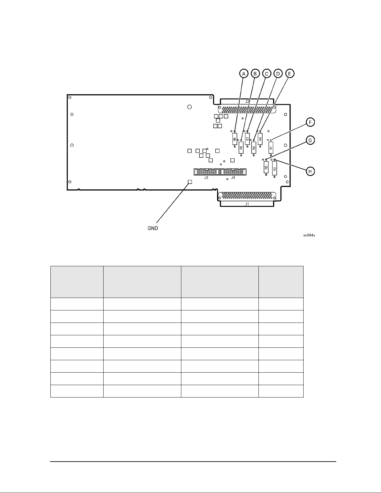
PNA Series Microwave Network Analyzers Troubleshooting
E8362B, E8363B, E8364B Power Up Troubleshooting
Figure 4-3 E8356-60021 Synthesizer/Reference Extender Measurement Points
Table 4-1 Extender Board Measurement Points
Measurement
Location
A power supply DVM +5.0
B power supply DVM −15.0
C power supply DVM −5.0
D power supply DVM +9
E power supply DVM +15
F power supply DVM +15
G power supply DVM +22
H power supply DVM +32
1. DVM=Digital volt meter
Signal Description Test Equipment
Used
1
Expected
Level (Vdc)
If All Supply Voltages Are Present
If all of the supplies have measured within tolerances, and the instrument still is not
functioning properly, refer to “Rear Panel Troubleshooting” on page 4-22.
Service Guide E8364-90026 4- 9
Page 94

Troubleshooting PNA Series Microwave Network Analyzers
Power Up Troubleshooting E8362B, E8363B, E8364B
If All Supply Voltages Are Missing
WARNING Disconnect the line-power cord before removing any assembly.
Procedures described in this document may be performed with
power supplied to the product while protective covers are removed.
Energy available at many points may, if contacted, result in personal
injury or loss of life.
It is necessary to sequentially remove all of the assemblies, taking care to disconnect the
line-power cord before each removal, and then to measure the supply voltages after each
removal.
If the missing supply voltages return to a “power on” condition after removal of an
assembly, suspect that assembly as being defective.
Remove the network analyzer assemblies in the order specified in the following steps (refer
to Chapter 7 for removal instructions).
1. Unplug the test set motherboard cable from the A16 test set motherboard.
2. Unplug the front panel interface cable from the A3 front panel interface board.
3. Remove the A6 SPAM board.
4. Remove the A8 fractional-N synthesizer board.
5. Remove the A10 frequency reference board.
6. Remove the A11 phase lock board.
7. Unplug the A30 floppy disk drive from the A14 system motherboard.
8. Unplug the A31 hard disk drive from the A15 CPU board.
The minimum required assemblies to power up the analyzer are:
• A4 power supply
• A14 system motherboard
• A15 CPU board
To further isolate the failure in the three remaining assemblies, measure the resistance on
the extender board (with the power turned off) from the power supply test points to “GND”.
Refer to Figure 4-3 on page 4-9. The voltages should be as shown in Table 4-2.
NOTE Make sure that the only assemblies plugged in are the three minimum
required assemblies listed above.
Check for shorts (zero Ω) or very low resistance (approximately 1 Ω). If a short or low
resistance is measured, isolate each of the remaining three boards in the following order,
and recheck the shorted test point after each board is removed. Note that the resistance
may be different from that listed in the table, but you should be able to determine if the
shorted condition has changed.
4-10 Service Guide E8364-90026
Page 95

PNA Series Microwave Network Analyzers Troubleshooting
E8362B, E8363B, E8364B Power Up Troubleshooting
Isolate the remaining three assemblies:
• remove the A15 CPU board
• remove the A4 power supply
• This leaves only the A14 system motherboard installed. If the measurements are still
incorrect, this is the suspected faulty assembly.
Table 4-2 Power Supply Voltages and Resistances
Measurement
Location
A +5.0 285
B -15.0 12.7 k
C -5.0 7.2 k
D +9 4.0 k
E +15 3.0 k
F +22 2.8 k
G+22890
H +32 2.6 k
Supply
(Vdc)
Approximate
Resistance (Ω)
Service Guide E8364-90026 4- 11
Page 96

Troubleshooting PNA Series Microwave Network Analyzers
Power Up Troubleshooting E8362B, E8363B, E8364B
If the Fans Are Not Operating
CAUTION The power supply may be in thermal shutdown if the instrument has been
operating without the fans running. Allow the instrument to cool down before
troubleshooting.
If all three fans are not operating, suspect a power supply problem or a defective A14
system motherboard. Refer to “Power Supply Check” on page 4-7 to check the individual
supplies. If the supplies are within specifications, the most probable cause is a defective
A14 system motherboard. Refer to “Removing and Replacing the A14 System
Motherboard” on page 7-26.
If only one or two fans are not functioning, and the power supplies are within
specifications, suspect the A14 system motherboard or a defective fan. Perform the
following procedure.
1. Remove the front panel assembly from the instrument. Refer to “Removing and
Replacing the Front Panel Assembly” on page 7-10.
2. Refer to Figure 4-4. Measure the fan voltages at J1, J3, and J4 on the A14 system
motherboard.
Figure 4-4 Fan Voltages
3. If the correct voltage is present and the fan connector is in good mechanical condition,
suspect a defective fan. Refer to “Removing and Replacing the Midweb and the B1
Fan” on page 7-77.
4. If the voltage is not present, suspect a defective A14 system motherboard. Refer to
“Removing and Replacing the A14 System Motherboard” on page 7-26.
4-12 Service Guide E8364-90026
Page 97

PNA Series Microwave Network Analyzers Troubleshooting
E8362B, E8363B, E8364B Power Up Troubleshooting
Troubleshooting LCD Display Problems
This procedure is intended to isolate the faulty assembly when the display is dark. If the
display is lit, but the color mix is faulty, refer to “A2 Display Test” on page 4-19.
NOTE There are no front panel adjustments for intensity and contrast of the LCD.
1. If the display is dim, the backlight assembly is defective. Refer to “Removing and
Replacing the Front Panel Assembly” on page 7-10.
2. If the display is dark (not visible), connect an external VGA monitor to the rear panel
VGA output connector on the instrument. Be aware that some multisync monitors
might not be able to lock to a 60 Hz sync pulse. If the video information is not present on
the external VGA monitor, the most probable cause is the A15 CPU board. Refer to
“Removing and Replacing the A15 CPU Board” on page 7-28.
3. If the external VGA monitor is functioning, verify that the front panel interface ribbon
cable is properly plugged into the motherboard connector.
4. If the front panel interface ribbon cable is properly connected, suspect that one or more
of the following is defective:
• inverter board (mounted on the display assembly)
• display lamp assembly
• A3 front panel interface board
• A2 display assembly
Refer to the following paragraphs to determine which of the above listed assemblies is
defective.
Creating the Test Setup
For easy access to measure the voltages on the inverter board and on the A3 front panel
interface board, it is best to disassemble the front panel and remove these two boards to
set in front of you for testing. Use the ribbon cables that come with the boards and the
analyzer as the supply source. Follow this procedure:
1. Turn off the analyzer.
2. Remove the front panel. Refer to “Removing and Replacing the Front Panel Assembly”
on page 7-10.
3. After the front panel is removed from the analyzer, isolate the inverter board by first
removing the display assembly. Refer to “Removing the A2 Display Assembly” on
page 7-12. Put the A2 display assembly and its ribbon cables aside.
4. Remove the A3 board by referring to “Removing the A3 Front Panel Interface Board” on
page 7-12. Put the A3 board aside.
5. Duplicate the board connections on your ESD safe test desk top by laying the A2 and A3
in front of the open-faced analyzer. Lay the A2 and A3 boards component-side down, the
A2 to the left of the A3, with the top of the boards towards you.
Service Guide E8364-90026 4- 13
Page 98

Troubleshooting PNA Series Microwave Network Analyzers
Power Up Troubleshooting E8362B, E8363B, E8364B
6. Connect the display ribbon cable and display lamp cable from A2 to A3. Connect the
front panel interface ribbon cable coming from the analyzer to the A3 board.
7. Turn the analyzer on and refer to “Verifying the Inverter Board” on page 4-14 and
“Verifying the A3 Front Panel Interface Board” on page 4-16 to test and troubleshoot
the boards.
Verifying the Inverter Board
WARNING High voltage is present on the inverter board and the A3 front panel
interface board. Be careful when measuring signals and voltages on
these boards.
1. To access the front panel boards for measurements, it is necessary to remove the front
panel assembly. Refer to “Removing and Replacing the Front Panel Assembly” on
page 7-10.
Using Figure 4-5 as a reference, measure the signals and voltages indicated in Table 4-3 on
page 4-14. If the signals and voltages measure good, the inverter board is functioning
correctly.
Figure 4-5 Inverter Board Test Point Locations
Table 4-3 Inverter Board, Voltages and Signals
Test Poi nt Signal or Voltage Test Po i nt Signal or Voltage
CN1 pin 1 +5.1 Vdc CN1 pin 5 0 V (ground)
CN1 pin 2 +5.1 Vdc CN1 pin 6 +2.54 V
CN1 pin 3 39 mV CN2 pin 1
CN1 pin 4 0 V (ground) CN2 pin 5
+400 V peak sinewave
@ 38 kHz
ac neutral
(referenced to pin 1)
After measuring the points CN1 and CN2, match the results and perform the rework as
indicated in the action column in Tabl e 4-4.
4-14 Service Guide E8364-90026
Page 99

PNA Series Microwave Network Analyzers Troubleshooting
E8362B, E8363B, E8364B Power Up Troubleshooting
Table 4-4 Inverter Board Troubleshooting Steps
Input
(CN1)
Good Good Replace the display lamp. Refer to “Removing and Replacing the
Good Bad Replace the inverter. Refer to “Removing and Replacing the Display
Bad Bad Refer to “Verifying the A3 Front Panel Interface Board” on page 4-16.
Output
(CN2)
Action
Display Inverter Board and the Display Lamp” on page 7-14.
Inverter Board and the Display Lamp” on page 7-14.
Service Guide E8364-90026 4- 15
Page 100

Troubleshooting PNA Series Microwave Network Analyzers
Power Up Troubleshooting E8362B, E8363B, E8364B
Verifying the A3 Front Panel Interface Board
To verify that the HSYNC (horizontal sync), VSYNC (vertical sync), and LCD clock are
functioning correctly, measure the signals listed in Table 4-5 and illustrated in Figure 4-6
on page 4-16. If all of these signals measure correctly, suspect a defective backlight or LCD.
The backlight is the most probable cause.
CAUTION Be careful not to short connector pins together when measuring these signals.
Table 4-5 A3 Front Panel Interface Board, Voltages and Signals
Signal Type Test Point Voltage Signal
HSYNC J2 pin 3 0 to +3 V 30.8 kHz square wave
VSYNC J2 pin 4 0 to +3 V 60 Hz square wave
CLOCK J2 pin 27 0 to +3.4 V pk-to-pk 25 MHz sine wave
Figure 4-6 Verifying HSYNC, VSYNC, and LCD Clock
If any of the three signal types is incorrect, replace the A3 front panel interface board.
Refer to “Removing the A3 Front Panel Interface Board” on page 7-12.
If all of the signal types are correct, replace the A2 display assembly. Refer to “Removing
the A2 Display Assembly” on page 7-12.
4-16 Service Guide E8364-90026
 Loading...