

Page 1

Service Guide
Agilent Technologies
PNA Series
RF Network Analyzers
E8356A, E8357A, and E8358A
Part Number E8356-90002
Printed in USA
March 2004
Supersedes: December 2001
© Agilent Technologies, Inc. 2000-2001, 2004
Page 2

Warranty Statement
THE MATERIAL CONTAINED IN THIS DOCUMENT IS PROVIDED “AS IS,” AND IS SUBJECT
TO BEING CHANGED, WITHOUT NOTICE, IN FUTURE EDITIONS. FURTHER, TO THE
MAXIMUM EXTENT PERMITTED BY APPLICABLE LAW, AGILENT DISCLAIMS ALL
WARRANTIES, EITHER EXPRESS OR IMPLIED WITH REGARD TO THIS MANUAL AND
ANY INFORMATION CONTAINED HEREIN, INCLUDING BUT NOT LIMITED TO THE
IMPLIED WARRANTIES OF MERCHANTABILITY AND FITNESS FOR A PARTICULAR
PURPOSE. AGILENT SHALL NOT BE LIABLE FOR ERRORS OR FOR INCIDENTAL
OR CONSEQUENTIAL DAMAGES IN CONNECTION WITH THE FURNISHING, USE, OR
PERFORMANCE OF THIS DOCUMENT OR ANY INFORMATION CONTAINED HEREIN.
SHOULD AGILENT AND THE USER HAVE A SEPARATE WRITTEN AGREEMENT WITH
WARRANTY TERMS COVERING THE MATERIAL IN THIS DOCUMENT THAT CONFLICT
WITH THESE TERMS, THE WARRANTY TERMS IN THE SEPARATE AGREEMENT WILL
CONTROL.
DFARS/Restricted Rights Notice
If software is for use in the performance of a U.S. Government prime contract or
subcontract, Software is delivered and licensed as “Commercial computer software” as
defined in DFAR 252.227-7014 (June 1995), or as a “commercial item” as defined in FAR
2.101(a) or as “Restricted computer software” as defined in FAR 52.227-19 (June 1987) or
any equivalent agency regulation or contract clause. Use, duplication or disclosure of
Software is subject to Agilent Technologies’ standard commercial license terms, and
non-DOD Departments and Agencies of the U.S. Government will receive no greater than
Restricted Rights as defined in FAR 52.227-19(c)(1-2) (June 1987). U.S. Government users
will receive no greater than Limited Rights as defined in FAR 52.227-14 (June 1987) or
DFAR 252.227-7015 (b)(2) (November 1995), as applicable in any technical data.
Certification
Agilent Technologies, Inc. certifies that this product met its published specifications at the
time of shipment from the factory. Agilent Technologies, Inc. further certifies that its
calibration measurements are traceable to the United States National Institute of
Standards and Technology, to the extent allowed by the Institute's calibration facility, and
to the calibration facilities of other International Standards Organization members.
ii Service Guide E8356-90002
Page 3

Assistance
Product maintenance agreements and other customer assistance agreements are available
for Agilent Technologies, Inc. products. For information about these agreements and for
other assistance, contact Agilent. Refer to “Contacting Agilent” on page 2-9.
Safety and Regulatory and Information
The safety and regulatory information pertaining to this product is located in Chapter 1,
“Safety and Regulatory Information.”
Safety Notes
The following safety notes are used throughout this manual. Familiarize yourself with
each of the notes and its meaning before operating this instrument. All pertinent safety
notes for using this product are located in Chapter 1, “Safety and Regulatory Information.”
WARNING
CAUTION
Warning denotes a hazard. It calls attention to a procedure which, if
not correctly performed or adhered to, could result in injury or loss
of life. Do not proceed beyond a warning note until the indicated
conditions are fully understood and met.
Caution denotes a hazard. It calls attention to a procedure that, if not
correctly performed or adhered to, could result in damage to or destruction of
the instrument. Do not proceed beyond a caution sign until the indicated
conditions are fully understood and met.
Service Guide E8356-90002 iii
Page 4
Documentation Map
The online Help files are embedded in the analyzer, offering quick
reference to programming and user documentation. From the Help
drop-down menu, you can access the Help system in five different
languages. Also, you can view the Analyzer Product Overview
multimedia presentation and access the analyzer’s Web page.
The Installation and Quick Start Guide helps you to quickly
familiarize yourself with the analyzer. Procedures are provided for
installing, configuring, and verifying the operation of the analyzer.
The CD-ROM provides the following:
•Installation and Quick Start Guide (PDF)
•Service Guide (PDF)
•Help system
•Network Analyzer Product Overview multimedia presentation
Printing Copies of Documentation on the Web
To print copies of documentation from the Web, download the PDF file from the Agilent
web site:
•Go to http://www.agilent.com.
• Enter the document’s part number (located on the title page) in the Quick Search box.
• Click GO.
iv Service Guide E8356-90002
Page 5

Contents
1 Safety and Regulatory Information
Information in This Chapter . . . . . . . . . . . . . . . . . . . . . . . . . . . . . . . . . . . . . . . . . . . . . . . . . . .1-2
Chapter One at-a-Glance . . . . . . . . . . . . . . . . . . . . . . . . . . . . . . . . . . . . . . . . . . . . . . . . . . . .1-2
Safety Symbols . . . . . . . . . . . . . . . . . . . . . . . . . . . . . . . . . . . . . . . . . . . . . . . . . . . . . . . . . . . . .1-3
General Safety Considerations . . . . . . . . . . . . . . . . . . . . . . . . . . . . . . . . . . . . . . . . . . . . . . . . .1-3
Safety Earth Ground . . . . . . . . . . . . . . . . . . . . . . . . . . . . . . . . . . . . . . . . . . . . . . . . . . . . . . .1-3
Before Applying Power . . . . . . . . . . . . . . . . . . . . . . . . . . . . . . . . . . . . . . . . . . . . . . . . . . . . . .1-3
Servicing . . . . . . . . . . . . . . . . . . . . . . . . . . . . . . . . . . . . . . . . . . . . . . . . . . . . . . . . . . . . . . . . .1-4
Electrostatic Discharge Protection . . . . . . . . . . . . . . . . . . . . . . . . . . . . . . . . . . . . . . . . . . . . . .1-5
Regulatory Information . . . . . . . . . . . . . . . . . . . . . . . . . . . . . . . . . . . . . . . . . . . . . . . . . . . . . . .1-6
Instrument Markings . . . . . . . . . . . . . . . . . . . . . . . . . . . . . . . . . . . . . . . . . . . . . . . . . . . . . . .1-6
Lithium Battery Disposal . . . . . . . . . . . . . . . . . . . . . . . . . . . . . . . . . . . . . . . . . . . . . . . . . . . .1-6
Compliance with Canadian EMC Requirements . . . . . . . . . . . . . . . . . . . . . . . . . . . . . . . . .1-7
Compliance with German FTZ Emissions Requirements . . . . . . . . . . . . . . . . . . . . . . . . . .1-7
Compliance with German Noise Requirements . . . . . . . . . . . . . . . . . . . . . . . . . . . . . . . . . .1-7
2 General Product Information
Information in This Chapter . . . . . . . . . . . . . . . . . . . . . . . . . . . . . . . . . . . . . . . . . . . . . . . . . . .2-2
Chapter Two at-a-Glance . . . . . . . . . . . . . . . . . . . . . . . . . . . . . . . . . . . . . . . . . . . . . . . . . . . .2-2
Maintenance . . . . . . . . . . . . . . . . . . . . . . . . . . . . . . . . . . . . . . . . . . . . . . . . . . . . . . . . . . . . . . . .2-3
Physical Maintenance . . . . . . . . . . . . . . . . . . . . . . . . . . . . . . . . . . . . . . . . . . . . . . . . . . . . . . .2-3
Electrical Maintenance . . . . . . . . . . . . . . . . . . . . . . . . . . . . . . . . . . . . . . . . . . . . . . . . . . . . . .2-3
Analyzer Options, Upgrades, and Accessories . . . . . . . . . . . . . . . . . . . . . . . . . . . . . . . . . . . . .2-3
Option 006, Extended Frequency Range to 6 GHz . . . . . . . . . . . . . . . . . . . . . . . . . . . . . . . .2-3
Option 009, Extended Frequency Range to 9 GHz . . . . . . . . . . . . . . . . . . . . . . . . . . . . . . . .2-3
Option 010, Time Domain. . . . . . . . . . . . . . . . . . . . . . . . . . . . . . . . . . . . . . . . . . . . . . . . . . . .2-3
Option 015, Configurable Test Set . . . . . . . . . . . . . . . . . . . . . . . . . . . . . . . . . . . . . . . . . . . . .2-4
Option 098, Upgraded CPU Board. . . . . . . . . . . . . . . . . . . . . . . . . . . . . . . . . . . . . . . . . . . . .2-4
Option 099, Firmware Upgrade . . . . . . . . . . . . . . . . . . . . . . . . . . . . . . . . . . . . . . . . . . . . . . .2-4
CD-RW Drive. . . . . . . . . . . . . . . . . . . . . . . . . . . . . . . . . . . . . . . . . . . . . . . . . . . . . . . . . . . . . .2-4
USB Hub . . . . . . . . . . . . . . . . . . . . . . . . . . . . . . . . . . . . . . . . . . . . . . . . . . . . . . . . . . . . . . . . .2-4
Option UK6, Calibration Certificate and Data . . . . . . . . . . . . . . . . . . . . . . . . . . . . . . . . . . .2-5
Option 1CM, Rack Mount Flange Kit for Instruments without Handles . . . . . . . . . . . . . .2-5
Option 1CP, Rack Mount Flange Kit for Instruments with Handles . . . . . . . . . . . . . . . . . .2-5
Required Service Test Equipment . . . . . . . . . . . . . . . . . . . . . . . . . . . . . . . . . . . . . . . . . . . . . . .2-6
Agilent Support, Services, and Assistance . . . . . . . . . . . . . . . . . . . . . . . . . . . . . . . . . . . . . . . .2-8
Service and Support Options . . . . . . . . . . . . . . . . . . . . . . . . . . . . . . . . . . . . . . . . . . . . . . . . .2-8
Calibration Options. . . . . . . . . . . . . . . . . . . . . . . . . . . . . . . . . . . . . . . . . . . . . . . . . . . . . . . . .2-8
Contacting Agilent . . . . . . . . . . . . . . . . . . . . . . . . . . . . . . . . . . . . . . . . . . . . . . . . . . . . . . . . .2-9
Shipping Your Analyzer to Agilent for Service or Repair . . . . . . . . . . . . . . . . . . . . . . . . . .2-10
Service Guide E8356-90002 Contents-v
Page 6

Contents
3 Tests and Adjustments
Information in This Chapter . . . . . . . . . . . . . . . . . . . . . . . . . . . . . . . . . . . . . . . . . . . . . . . . . . .3-2
Chapter Three at-a-Glance . . . . . . . . . . . . . . . . . . . . . . . . . . . . . . . . . . . . . . . . . . . . . . . . . . 3-2
Before You Begin . . . . . . . . . . . . . . . . . . . . . . . . . . . . . . . . . . . . . . . . . . . . . . . . . . . . . . . . . . . . 3-4
Verify the Operating Environment . . . . . . . . . . . . . . . . . . . . . . . . . . . . . . . . . . . . . . . . . . . . 3-4
Protect Against Electrostatic Discharge (ESD) . . . . . . . . . . . . . . . . . . . . . . . . . . . . . . . . . . 3-4
Allow the Analyzer to Warm Up . . . . . . . . . . . . . . . . . . . . . . . . . . . . . . . . . . . . . . . . . . . . . . 3-4
Review the Principles of Connector Care . . . . . . . . . . . . . . . . . . . . . . . . . . . . . . . . . . . . . . . 3-5
About System Verification and Performance Tests . . . . . . . . . . . . . . . . . . . . . . . . . . . . . . . . . 3-6
System Specifications. . . . . . . . . . . . . . . . . . . . . . . . . . . . . . . . . . . . . . . . . . . . . . . . . . . . . . . 3-6
Instrument Specifications . . . . . . . . . . . . . . . . . . . . . . . . . . . . . . . . . . . . . . . . . . . . . . . . . . . 3-6
System Verification Procedure . . . . . . . . . . . . . . . . . . . . . . . . . . . . . . . . . . . . . . . . . . . . . . . 3-7
Performance Tests . . . . . . . . . . . . . . . . . . . . . . . . . . . . . . . . . . . . . . . . . . . . . . . . . . . . . . . . . 3-7
Certificate of Calibration . . . . . . . . . . . . . . . . . . . . . . . . . . . . . . . . . . . . . . . . . . . . . . . . . . . .3-7
ANSI/NCSL Z540–1–1994 Verification . . . . . . . . . . . . . . . . . . . . . . . . . . . . . . . . . . . . . . . . . . 3-8
Non-ANSI/NCSL Z540–1–1994 Verification . . . . . . . . . . . . . . . . . . . . . . . . . . . . . . . . . . . . . . 3-9
Preliminary Checks . . . . . . . . . . . . . . . . . . . . . . . . . . . . . . . . . . . . . . . . . . . . . . . . . . . . . . . . . 3-10
The Operator’s Check. . . . . . . . . . . . . . . . . . . . . . . . . . . . . . . . . . . . . . . . . . . . . . . . . . . . . . 3-10
The Test Port Cable Checks. . . . . . . . . . . . . . . . . . . . . . . . . . . . . . . . . . . . . . . . . . . . . . . . . 3-13
System Verification . . . . . . . . . . . . . . . . . . . . . . . . . . . . . . . . . . . . . . . . . . . . . . . . . . . . . . . . . 3-20
What the System Verification Verifies . . . . . . . . . . . . . . . . . . . . . . . . . . . . . . . . . . . . . . . . 3-20
Measurement Uncertainty. . . . . . . . . . . . . . . . . . . . . . . . . . . . . . . . . . . . . . . . . . . . . . . . . . 3-21
Measurement Traceability. . . . . . . . . . . . . . . . . . . . . . . . . . . . . . . . . . . . . . . . . . . . . . . . . . 3-22
Performing System Verification. . . . . . . . . . . . . . . . . . . . . . . . . . . . . . . . . . . . . . . . . . . . . . 3-23
Performance Tests (Agilent N2721A Software Package). . . . . . . . . . . . . . . . . . . . . . . . . . . . 3-30
Source Power Accuracy Test . . . . . . . . . . . . . . . . . . . . . . . . . . . . . . . . . . . . . . . . . . . . . . . . 3-30
Source Power Linearity Test . . . . . . . . . . . . . . . . . . . . . . . . . . . . . . . . . . . . . . . . . . . . . . . . 3-31
Frequency Accuracy Test . . . . . . . . . . . . . . . . . . . . . . . . . . . . . . . . . . . . . . . . . . . . . . . . . . . 3-31
Trace Noise Test . . . . . . . . . . . . . . . . . . . . . . . . . . . . . . . . . . . . . . . . . . . . . . . . . . . . . . . . . . 3-32
Receiver Compression Test . . . . . . . . . . . . . . . . . . . . . . . . . . . . . . . . . . . . . . . . . . . . . . . . . 3-32
Noise Floor Test . . . . . . . . . . . . . . . . . . . . . . . . . . . . . . . . . . . . . . . . . . . . . . . . . . . . . . . . . . 3-33
Calibration Coefficient Test . . . . . . . . . . . . . . . . . . . . . . . . . . . . . . . . . . . . . . . . . . . . . . . . . 3-34
System Crosstalk Test . . . . . . . . . . . . . . . . . . . . . . . . . . . . . . . . . . . . . . . . . . . . . . . . . . . . . 3-35
Dynamic Accuracy Test . . . . . . . . . . . . . . . . . . . . . . . . . . . . . . . . . . . . . . . . . . . . . . . . . . . . 3-35
Power Meter Accuracy Test . . . . . . . . . . . . . . . . . . . . . . . . . . . . . . . . . . . . . . . . . . . . . . . . . 3-37
Adjustments . . . . . . . . . . . . . . . . . . . . . . . . . . . . . . . . . . . . . . . . . . . . . . . . . . . . . . . . . . . . . . . 3-42
Source Calibration Adjustment . . . . . . . . . . . . . . . . . . . . . . . . . . . . . . . . . . . . . . . . . . . . . . 3-43
Receiver Calibration Adjustment . . . . . . . . . . . . . . . . . . . . . . . . . . . . . . . . . . . . . . . . . . . . 3-44
LO Power Adjustment . . . . . . . . . . . . . . . . . . . . . . . . . . . . . . . . . . . . . . . . . . . . . . . . . . . . . 3-46
10 MHz Frequency Reference Adjustment . . . . . . . . . . . . . . . . . . . . . . . . . . . . . . . . . . . . . 3-47
3.8 GHz PMYO Frequency Adjustment . . . . . . . . . . . . . . . . . . . . . . . . . . . . . . . . . . . . . . . 3-48
4 Troubleshooting
Information in This Chapter . . . . . . . . . . . . . . . . . . . . . . . . . . . . . . . . . . . . . . . . . . . . . . . . . . .4-2
Chapter Four at-a-Glance . . . . . . . . . . . . . . . . . . . . . . . . . . . . . . . . . . . . . . . . . . . . . . . . . . . 4-2
Protect Against Electrostatic Discharge (ESD) . . . . . . . . . . . . . . . . . . . . . . . . . . . . . . . . . . . . 4-3
Assembly Replacement Sequence. . . . . . . . . . . . . . . . . . . . . . . . . . . . . . . . . . . . . . . . . . . . . . . 4-3
Getting Started With Troubleshooting. . . . . . . . . . . . . . . . . . . . . . . . . . . . . . . . . . . . . . . . . . . 4-4
Check the Basics. . . . . . . . . . . . . . . . . . . . . . . . . . . . . . . . . . . . . . . . . . . . . . . . . . . . . . . . . . . 4-4
Contents-vi Service Guide E8356-90002
Page 7

Contents
Troubleshooting Organization . . . . . . . . . . . . . . . . . . . . . . . . . . . . . . . . . . . . . . . . . . . . . . . .4-5
Power Up Troubleshooting. . . . . . . . . . . . . . . . . . . . . . . . . . . . . . . . . . . . . . . . . . . . . . . . . . . . .4-6
Power Supply Check . . . . . . . . . . . . . . . . . . . . . . . . . . . . . . . . . . . . . . . . . . . . . . . . . . . . . . . .4-7
If the Fans Are Not Operating . . . . . . . . . . . . . . . . . . . . . . . . . . . . . . . . . . . . . . . . . . . . . . .4-12
Troubleshooting LCD Display Problems . . . . . . . . . . . . . . . . . . . . . . . . . . . . . . . . . . . . . . .4-13
Creating the Test Setup . . . . . . . . . . . . . . . . . . . . . . . . . . . . . . . . . . . . . . . . . . . . . . . . . . . .4-13
Verifying the Inverter Board . . . . . . . . . . . . . . . . . . . . . . . . . . . . . . . . . . . . . . . . . . . . . . . .4-14
Verifying the A3 Front Panel Interface Board Assembly . . . . . . . . . . . . . . . . . . . . . . . . . .4-16
Front Panel Troubleshooting . . . . . . . . . . . . . . . . . . . . . . . . . . . . . . . . . . . . . . . . . . . . . . . . . .4-17
A1 Front Panel Keypad and RPG Test. . . . . . . . . . . . . . . . . . . . . . . . . . . . . . . . . . . . . . . . .4-17
A2 Display Test . . . . . . . . . . . . . . . . . . . . . . . . . . . . . . . . . . . . . . . . . . . . . . . . . . . . . . . . . . .4-19
A3 Front Panel Interface Board Assembly . . . . . . . . . . . . . . . . . . . . . . . . . . . . . . . . . . . . .4-20
Rear Panel Troubleshooting . . . . . . . . . . . . . . . . . . . . . . . . . . . . . . . . . . . . . . . . . . . . . . . . . .4-21
Checking the USB Port. . . . . . . . . . . . . . . . . . . . . . . . . . . . . . . . . . . . . . . . . . . . . . . . . . . . .4-21
Checking the SERIAL (RS-232), PARALLEL (1284-C) or VGA Port . . . . . . . . . . . . . . . . .4-21
Checking the GPIB Port . . . . . . . . . . . . . . . . . . . . . . . . . . . . . . . . . . . . . . . . . . . . . . . . . . . .4-22
LAN Troubleshooting . . . . . . . . . . . . . . . . . . . . . . . . . . . . . . . . . . . . . . . . . . . . . . . . . . . . . .4-23
Measurement System Troubleshooting. . . . . . . . . . . . . . . . . . . . . . . . . . . . . . . . . . . . . . . . . .4-27
Verifying the A, B, R1, and R2 Traces . . . . . . . . . . . . . . . . . . . . . . . . . . . . . . . . . . . . . . . . .4-27
Where to Begin Troubleshooting . . . . . . . . . . . . . . . . . . . . . . . . . . . . . . . . . . . . . . . . . . . . .4-28
Checking the Source Assembly Group . . . . . . . . . . . . . . . . . . . . . . . . . . . . . . . . . . . . . . . . .4-31
Checking the Signal Separation Group . . . . . . . . . . . . . . . . . . . . . . . . . . . . . . . . . . . . . . . .4-41
Checking the Receiver Assembly Group . . . . . . . . . . . . . . . . . . . . . . . . . . . . . . . . . . . . . . .4-45
Instrument Block Diagrams Sheet 1 . . . . . . . . . . . . . . . . . . . . . . . . . . . . . . . . . . . . . . . . . . . .4-49
PNA Series RF Network Analyzers E8356A,E8357A,E8358A . . . . . . . . . . . . . . . . . . . . . .4-49
Instrument Block Diagrams Sheet 2 . . . . . . . . . . . . . . . . . . . . . . . . . . . . . . . . . . . . . . . . . . . .4-51
Option 015 E8356A,E8357A,E8358A. . . . . . . . . . . . . . . . . . . . . . . . . . . . . . . . . . . . . . . . . .4-51
5 Theory of Operation
Information in This Chapter . . . . . . . . . . . . . . . . . . . . . . . . . . . . . . . . . . . . . . . . . . . . . . . . . . .5-2
Chapter Five at-a-Glance . . . . . . . . . . . . . . . . . . . . . . . . . . . . . . . . . . . . . . . . . . . . . . . . . . . .5-2
Network Analyzer System Operation . . . . . . . . . . . . . . . . . . . . . . . . . . . . . . . . . . . . . . . . . . . .5-3
Functional Groups of the Network Analyzer. . . . . . . . . . . . . . . . . . . . . . . . . . . . . . . . . . . . .5-3
Source Group Operation . . . . . . . . . . . . . . . . . . . . . . . . . . . . . . . . . . . . . . . . . . . . . . . . . . . . . .5-5
Band Modes . . . . . . . . . . . . . . . . . . . . . . . . . . . . . . . . . . . . . . . . . . . . . . . . . . . . . . . . . . . . . . .5-5
A8 Fractional-N Synthesizer Board Assembly and A17 LODA . . . . . . . . . . . . . . . . . . . . . .5-8
A10 Frequency Reference Board Assembly . . . . . . . . . . . . . . . . . . . . . . . . . . . . . . . . . . . . . .5-8
A11 Phase Lock Board Assembly . . . . . . . . . . . . . . . . . . . . . . . . . . . . . . . . . . . . . . . . . . . . . .5-8
A12 Source Assembly . . . . . . . . . . . . . . . . . . . . . . . . . . . . . . . . . . . . . . . . . . . . . . . . . . . . . . .5-9
Rear Panel Interconnects . . . . . . . . . . . . . . . . . . . . . . . . . . . . . . . . . . . . . . . . . . . . . . . . . . . .5-9
Signal Separation Group Operation . . . . . . . . . . . . . . . . . . . . . . . . . . . . . . . . . . . . . . . . . . . .5-10
A22 Switch Splitter . . . . . . . . . . . . . . . . . . . . . . . . . . . . . . . . . . . . . . . . . . . . . . . . . . . . . . . .5-10
A23 and A24 Test Port Couplers . . . . . . . . . . . . . . . . . . . . . . . . . . . . . . . . . . . . . . . . . . . . .5-10
A25 and A26 70 dB Step Attenuators . . . . . . . . . . . . . . . . . . . . . . . . . . . . . . . . . . . . . . . . .5-11
Option 015 Configurable Test Set . . . . . . . . . . . . . . . . . . . . . . . . . . . . . . . . . . . . . . . . . . . .5-12
Receiver Group Operation . . . . . . . . . . . . . . . . . . . . . . . . . . . . . . . . . . . . . . . . . . . . . . . . . . . .5-15
A18, A19, A20, and A21 Receiver Modules . . . . . . . . . . . . . . . . . . . . . . . . . . . . . . . . . . . . .5-15
A16 Test Set Motherboard Assembly . . . . . . . . . . . . . . . . . . . . . . . . . . . . . . . . . . . . . . . . . .5-15
A6 SPAM Board Assembly (Analog Description) . . . . . . . . . . . . . . . . . . . . . . . . . . . . . . . .5-21
Service Guide E8356-90002 Contents-vii
Page 8

Contents
Digital Processing and Digital Control Group Operation . . . . . . . . . . . . . . . . . . . . . . . . . . . 5-22
Front Panel Subgroup . . . . . . . . . . . . . . . . . . . . . . . . . . . . . . . . . . . . . . . . . . . . . . . . . . . . . 5-22
Data Acquisition and Processing Subgroup . . . . . . . . . . . . . . . . . . . . . . . . . . . . . . . . . . . . 5-24
Power Supply Group Operation . . . . . . . . . . . . . . . . . . . . . . . . . . . . . . . . . . . . . . . . . . . . . . . 5-26
6 Replaceable Parts
Information in This Chapter . . . . . . . . . . . . . . . . . . . . . . . . . . . . . . . . . . . . . . . . . . . . . . . . . . .6-2
Chapter Six at-a-Glance. . . . . . . . . . . . . . . . . . . . . . . . . . . . . . . . . . . . . . . . . . . . . . . . . . . . .6-2
Ordering Information . . . . . . . . . . . . . . . . . . . . . . . . . . . . . . . . . . . . . . . . . . . . . . . . . . . . . . . . 6-3
Assembly Replacement Sequence. . . . . . . . . . . . . . . . . . . . . . . . . . . . . . . . . . . . . . . . . . . . . . . 6-4
Rebuilt-Exchange Assemblies. . . . . . . . . . . . . . . . . . . . . . . . . . . . . . . . . . . . . . . . . . . . . . . . . . 6-5
Replaceable Parts Listings . . . . . . . . . . . . . . . . . . . . . . . . . . . . . . . . . . . . . . . . . . . . . . . . . . . . 6-6
Front Panel Assembly . . . . . . . . . . . . . . . . . . . . . . . . . . . . . . . . . . . . . . . . . . . . . . . . . . . . . .6-8
Top Assemblies and Hardware . . . . . . . . . . . . . . . . . . . . . . . . . . . . . . . . . . . . . . . . . . . . . . 6-10
Bottom Assemblies and Hardware, Standard . . . . . . . . . . . . . . . . . . . . . . . . . . . . . . . . . . 6-12
Bottom Assemblies and Hardware, Option 015 . . . . . . . . . . . . . . . . . . . . . . . . . . . . . . . . . 6-14
Top Cables. . . . . . . . . . . . . . . . . . . . . . . . . . . . . . . . . . . . . . . . . . . . . . . . . . . . . . . . . . . . . . . 6-16
Bottom Cables, Standard . . . . . . . . . . . . . . . . . . . . . . . . . . . . . . . . . . . . . . . . . . . . . . . . . . . 6-18
Bottom Cables, Option 015 . . . . . . . . . . . . . . . . . . . . . . . . . . . . . . . . . . . . . . . . . . . . . . . . . 6-20
Internal Hardware and Parts . . . . . . . . . . . . . . . . . . . . . . . . . . . . . . . . . . . . . . . . . . . . . . . 6-22
Hard Disk Drive Assembly . . . . . . . . . . . . . . . . . . . . . . . . . . . . . . . . . . . . . . . . . . . . . . . . . 6-24
Rear Panel Assembly . . . . . . . . . . . . . . . . . . . . . . . . . . . . . . . . . . . . . . . . . . . . . . . . . . . . . . 6-25
External Parts . . . . . . . . . . . . . . . . . . . . . . . . . . . . . . . . . . . . . . . . . . . . . . . . . . . . . . . . . . . 6-26
Miscellaneous Part Numbers. . . . . . . . . . . . . . . . . . . . . . . . . . . . . . . . . . . . . . . . . . . . . . . . 6-28
7 Repair and Replacement Procedures
Information in This Chapter . . . . . . . . . . . . . . . . . . . . . . . . . . . . . . . . . . . . . . . . . . . . . . . . . . .7-2
Chapter Seven at-a-Glance . . . . . . . . . . . . . . . . . . . . . . . . . . . . . . . . . . . . . . . . . . . . . . . . . . 7-2
Assembly Replacement Sequence. . . . . . . . . . . . . . . . . . . . . . . . . . . . . . . . . . . . . . . . . . . . . . . 7-2
Personal Safety Warnings. . . . . . . . . . . . . . . . . . . . . . . . . . . . . . . . . . . . . . . . . . . . . . . . . . . . .7-3
Electrostatic Discharge (ESD) Protection . . . . . . . . . . . . . . . . . . . . . . . . . . . . . . . . . . . . . . . . 7-3
Removal and Replacement Procedures . . . . . . . . . . . . . . . . . . . . . . . . . . . . . . . . . . . . . . . . . . 7-4
Removing the Covers. . . . . . . . . . . . . . . . . . . . . . . . . . . . . . . . . . . . . . . . . . . . . . . . . . . . . . . . . 7-6
Removing and Replacing the Front Panel Assembly. . . . . . . . . . . . . . . . . . . . . . . . . . . . . . . . 7-8
Removing and Replacing Front Panel Subassemblies. . . . . . . . . . . . . . . . . . . . . . . . . . . . . . 7-10
Removing and Replacing the Display Inverter Board and the Display Lamp . . . . . . . . . . . 7-12
Removing and Replacing the A4 Power Supply Assembly . . . . . . . . . . . . . . . . . . . . . . . . . . 7-14
Removing and Replacing the A6, A8, and A10 Board Assemblies . . . . . . . . . . . . . . . . . . . . 7-16
Removing and Replacing the A11 Phase Lock Board Assembly. . . . . . . . . . . . . . . . . . . . . . 7-18
Removing and Replacing the A12 Source Assembly . . . . . . . . . . . . . . . . . . . . . . . . . . . . . . . 7-20
Removing and Replacing the A14 Motherboard Assembly . . . . . . . . . . . . . . . . . . . . . . . . . . 7-22
Removing and Replacing the A15 CPU Board Assembly . . . . . . . . . . . . . . . . . . . . . . . . . . . 7-24
Removing and Replacing the A16 Test Set Motherboard Assembly. . . . . . . . . . . . . . . . . . . 7-26
Removing and Replacing the A17 Local Oscillator Distribution Assembly (LODA) . . . . . . 7-28
Removing and Replacing the A18, A19, A20, and A21 Receiver Module Assemblies . . . . . 7-30
Removing and Replacing the A22 Switch Splitter Assembly . . . . . . . . . . . . . . . . . . . . . . . . 7-32
Removing and Replacing the A23 and A24 Test Port Couplers . . . . . . . . . . . . . . . . . . . . . . 7-34
Removing and Replacing the A25 and A26 70 dB Step Attenuators . . . . . . . . . . . . . . . . . . 7-36
Contents-viii Service Guide E8356-90002
Page 9

Contents
Option 015, Removing and Replacing the A27 and A28 35 dB Step Attenuators . . . . . . . .7-38
Removing and Replacing the A30 Floppy Disk Drive . . . . . . . . . . . . . . . . . . . . . . . . . . . . . .7-40
Removing and Replacing the A31 Hard Disk Drive Assembly (HDDA) . . . . . . . . . . . . . . . .7-42
Copy Unique Files from the Hard Disk . . . . . . . . . . . . . . . . . . . . . . . . . . . . . . . . . . . . . . . .7-42
Set Up the Agilent Administrator Password. . . . . . . . . . . . . . . . . . . . . . . . . . . . . . . . . . . .7-46
Install Backup Files onto the New Hard Disk Drive . . . . . . . . . . . . . . . . . . . . . . . . . . . . .7-47
Post-Repair Procedures. . . . . . . . . . . . . . . . . . . . . . . . . . . . . . . . . . . . . . . . . . . . . . . . . . . . .7-48
Removing and Replacing the Midweb and the B1 Fan . . . . . . . . . . . . . . . . . . . . . . . . . . . . .7-49
Reconfiguring the Pinout of the Handler I/O Port . . . . . . . . . . . . . . . . . . . . . . . . . . . . . . . . .7-52
Post-Repair Procedures . . . . . . . . . . . . . . . . . . . . . . . . . . . . . . . . . . . . . . . . . . . . . . . . . . . . . .7-53
A Error Terms
Information in This Appendix . . . . . . . . . . . . . . . . . . . . . . . . . . . . . . . . . . . . . . . . . . . . . . . . . A-2
Appendix A at-a-Glance . . . . . . . . . . . . . . . . . . . . . . . . . . . . . . . . . . . . . . . . . . . . . . . . . . . . A-2
Using Error Terms as a Diagnostic Tool . . . . . . . . . . . . . . . . . . . . . . . . . . . . . . . . . . . . . . . . . A-3
Preventive Maintenance . . . . . . . . . . . . . . . . . . . . . . . . . . . . . . . . . . . . . . . . . . . . . . . . . . . . A-3
Troubleshooting. . . . . . . . . . . . . . . . . . . . . . . . . . . . . . . . . . . . . . . . . . . . . . . . . . . . . . . . . . . A-3
Performing Measurement Calibration . . . . . . . . . . . . . . . . . . . . . . . . . . . . . . . . . . . . . . . . . . A-4
Using Flowgraphs to Identify Error Terms . . . . . . . . . . . . . . . . . . . . . . . . . . . . . . . . . . . . . . A-4
Accessing Error Terms . . . . . . . . . . . . . . . . . . . . . . . . . . . . . . . . . . . . . . . . . . . . . . . . . . . . . . . A-6
Manual Access to Error Terms. . . . . . . . . . . . . . . . . . . . . . . . . . . . . . . . . . . . . . . . . . . . . . . A-6
Programmatic Access to Error Terms . . . . . . . . . . . . . . . . . . . . . . . . . . . . . . . . . . . . . . . . . A-7
Typical Error Term Data . . . . . . . . . . . . . . . . . . . . . . . . . . . . . . . . . . . . . . . . . . . . . . . . . . . . . A-8
If Error Terms Seem Worse than Typical Values . . . . . . . . . . . . . . . . . . . . . . . . . . . . . . . . A-8
Directivity (EDF and EDR) . . . . . . . . . . . . . . . . . . . . . . . . . . . . . . . . . . . . . . . . . . . . . . . . . A-9
Source Match (ESF and ESR) . . . . . . . . . . . . . . . . . . . . . . . . . . . . . . . . . . . . . . . . . . . . . . A-10
Load Match (ELF and ELR) . . . . . . . . . . . . . . . . . . . . . . . . . . . . . . . . . . . . . . . . . . . . . . . . A-11
Reflection Tracking (ERF and ERR) . . . . . . . . . . . . . . . . . . . . . . . . . . . . . . . . . . . . . . . . . A-12
Transmission Tracking (ETF and ETR) . . . . . . . . . . . . . . . . . . . . . . . . . . . . . . . . . . . . . . A-13
Isolation (EXF and EXR) . . . . . . . . . . . . . . . . . . . . . . . . . . . . . . . . . . . . . . . . . . . . . . . . . . A-14
B Option Enable Utility
Information in This Appendix . . . . . . . . . . . . . . . . . . . . . . . . . . . . . . . . . . . . . . . . . . . . . . . . . B-2
Appendix B at-a-Glance . . . . . . . . . . . . . . . . . . . . . . . . . . . . . . . . . . . . . . . . . . . . . . . . . . . . B-2
Accessing the Option Enable Utility . . . . . . . . . . . . . . . . . . . . . . . . . . . . . . . . . . . . . . . . . . . . B-3
Enabling or Removing Options . . . . . . . . . . . . . . . . . . . . . . . . . . . . . . . . . . . . . . . . . . . . . . . . B-4
Repairing and Recovering Option Data . . . . . . . . . . . . . . . . . . . . . . . . . . . . . . . . . . . . . . . . . B-5
Recovery of Data After Repair . . . . . . . . . . . . . . . . . . . . . . . . . . . . . . . . . . . . . . . . . . . . . . . B-5
Recovery of Data if Option or Model Numbers are Incorrect . . . . . . . . . . . . . . . . . . . . . . . B-5
Installing or Changing a Serial Number . . . . . . . . . . . . . . . . . . . . . . . . . . . . . . . . . . . . . . . . B-6
C Firmware Upgrades
Information in This Appendix . . . . . . . . . . . . . . . . . . . . . . . . . . . . . . . . . . . . . . . . . . . . . . . . . C-2
Appendix C at-a-Glance . . . . . . . . . . . . . . . . . . . . . . . . . . . . . . . . . . . . . . . . . . . . . . . . . . . . C-2
Downloading from the Internet . . . . . . . . . . . . . . . . . . . . . . . . . . . . . . . . . . . . . . . . . . . . . . . . C-2
Downloading Using Option 099, Firmware Upgrade . . . . . . . . . . . . . . . . . . . . . . . . . . . . . . . C-3
Installation Requirements . . . . . . . . . . . . . . . . . . . . . . . . . . . . . . . . . . . . . . . . . . . . . . . . . . C-3
Downloading from a USB CD Drive Connected to the Analyzer . . . . . . . . . . . . . . . . . . . . C-3
Service Guide E8356-90002 Contents-ix
Page 10

Contents
Downloading from a Shared CD Drive Over the LAN . . . . . . . . . . . . . . . . . . . . . . . . . . . . .C-3
Downloading Over the LAN. . . . . . . . . . . . . . . . . . . . . . . . . . . . . . . . . . . . . . . . . . . . . . . . . . C-4
D Operating System Recovery
Information in This Appendix. . . . . . . . . . . . . . . . . . . . . . . . . . . . . . . . . . . . . . . . . . . . . . . . . .D-2
Appendix D at-a-Glance . . . . . . . . . . . . . . . . . . . . . . . . . . . . . . . . . . . . . . . . . . . . . . . . . . . . .D-2
Overview . . . . . . . . . . . . . . . . . . . . . . . . . . . . . . . . . . . . . . . . . . . . . . . . . . . . . . . . . . . . . . . . . .D-3
System Recovery Procedure . . . . . . . . . . . . . . . . . . . . . . . . . . . . . . . . . . . . . . . . . . . . . . . . . . .D-4
If the Operating System Does Not Boot from the Hard Disk Drive . . . . . . . . . . . . . . . . . .D-5
If the Operating System Does Not Boot from the Floppy Disk Drive . . . . . . . . . . . . . . . . .D-6
Contents-x Service Guide E8356-90002
Page 11

1 Safety and Regulatory Information
Service Guide E8356-90002 1-1
Page 12

Safety and Regulatory Information PNA Series RF Network Analyzers
Information in This Chapter
E8356A, E8357A, E8358A
Information in This Chapter
This chapter provides safety information that will help protect you and your network
analyzer. It also contains information that is required by various government regulatory
agencies.
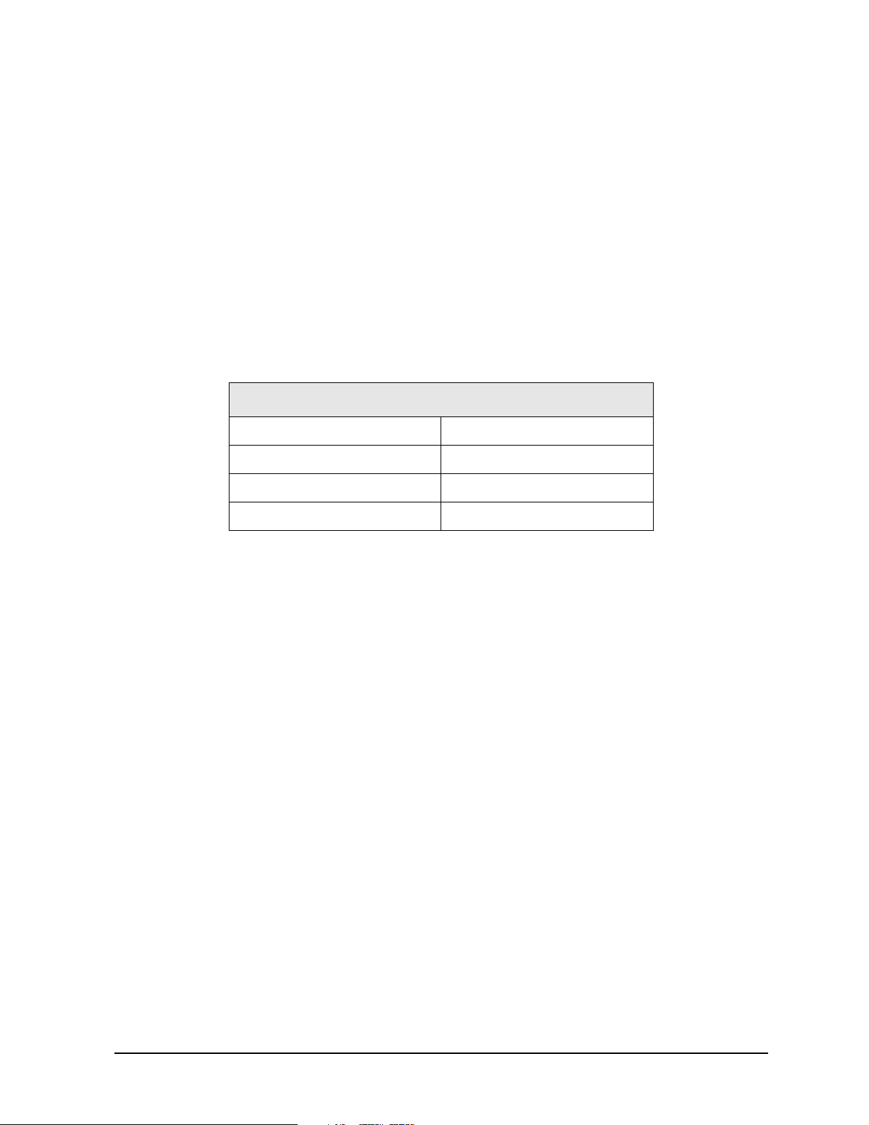
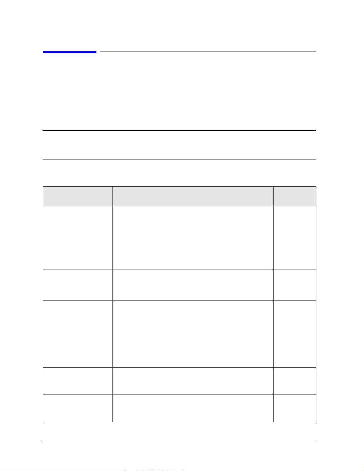
Chapter One at-a-Glance
Section Title Summary of Content Start Page
Safety Symbols
General Safety Considerations
Electrostatic Discharge
Protection
Regulatory Information
Descriptions of CAUTION and WARNING
symbols used throughout this manual.
A list of safety points to consider when
servicing your network analyzer.
A discussion of electrostatic discharge (ESD)
and related recommendations and
requirements for ESD protection.
Definitions of instrument markings.
Instructions for disposing of the analyzer’s
lithium battery.
Information on compliance with Canadian
EMC requirements.
Information on compliance with German
FTZ emissions requirements.
Information on compliance with German
noise requirements.
Page 1-3
Page 1-3
Page 1-5
Page 1-6
1-2 Service Guide E8356-90002
Page 13

PNA Series RF Network Analyzers Safety and Regulatory Information
E8356A, E8357A, E8358A Safety Symbols
Safety Symbols
The following safety symbols are used throughout this manual. Familiarize yourself with
each of the symbols and its meaning before operating this instrument.
CAUTION
WARNING
Caution denotes a hazard. It calls attention to a procedure that, if not
correctly performed or adhered to, could result in damage to or destruction of
the instrument. Do not proceed beyond a caution note until the indicated
conditions are fully understood and met.
Warning denotes a hazard. It calls attention to a procedure which, if
not correctly performed or adhered to, could result in injury or loss
of life. Do not proceed beyond a warning note until the indicated
conditions are fully understood and met.
General Safety Considerations
Safety Earth Ground
WARNING
This is a Safety Class I product (provided with a protective earthing
ground incorporated in the power cord). The mains plug shall only
be inserted in a socket outlet provided with a protective earth
contact. Any interruption of the protective conductor, inside or
outside of the instrument, will make the instrument dangerous.
Intentional interruption is prohibited.
Before Applying Power
CAUTION
CAUTION
CAUTION
CAUTION
Service Guide E8356-90002 1-3
This product is designed for use in Installation Category II and Pollution
Degree 2 per IEC 1010 and 664 respectively.
Make sure that the analyzer line voltage selector switch is set to the voltage
of the power supply and the correct fuse is installed.
Always use the three-prong AC power cord supplied with this product.
Failure to ensure adequate grounding by not using this cord may cause
product damage.
If this product is to be energized via an autotransformer make sure the
common terminal is connected to the neutral (grounded side of the mains
supply).
Page 14

Safety and Regulatory Information PNA Series RF Network Analyzers
General Safety Considerations
E8356A, E8357A, E8358A
Servicing
WARNING
WARNING
WARNING
WARNING
WARNING
WARNING
These servicing instructions are for use by qualified personnel only.
To avoid electrical shock, do not perform any servicing unless you
are qualified to do so.
The opening of covers or removal of parts may expose dangerous
voltages. Disconnect the instrument from all voltage sources while it
is opened.
Danger of explosion if battery is incorrectly replaced. Replace only
with the same or equivalent type recommended. Discard used
batteries according to manufacturer’s instructions.
Procedures described in this document may be performed with
power supplied to the product while protective covers are removed.
Energy available at many points may, if contacted, result in personal
injury.
The power cord is connected to internal capacitors that may remain
live for 5 seconds after disconnecting the plug from its power supply.
For continued protection against fire hazard, replace line fuse only
with same type and rating. The use of other fuses or material is
prohibited.
WARNING
The detachable power cord is the instrument disconnecting device.
It disconnects the mains circuits from the mains supply before other
parts of the instrument. The front panel switch is only a standby
switch and is not a LINE switch (disconnecting device).
1-4 Service Guide E8356-90002
Page 15

PNA Series RF Network Analyzers Safety and Regulatory Information
E8356A, E8357A, E8358A Electrostatic Discharge Protection
Electrostatic Discharge Protection
Protection against electrostatic discharge (ESD) is essential while removing assemblies
from or connecting cables to the network analyzer. Static electricity can build up on your
body and can easily damage sensitive internal circuit elements when discharged. Static
discharges too small to be felt can cause permanent damage. To prevent damage to the
instrument:
• always have a grounded, conductive table mat in front of your test equipment.
• always wear a grounded wrist strap, connected to a grounded conductive table mat,
having a 1 MΩ resistor in series with it, when handling components and assemblies or
when making connections.
• always wear a heel strap when working in an area with a conductive floor. If you are
uncertain about the conductivity of your floor, wear a heel strap.
• always ground yourself before you clean, inspect, or make a connection to a
static-sensitive device or test port. You can, for example, grasp the grounded outer shell
of the test port or cable connector briefly.
• always ground the center conductor of a test cable before making a connection to the
analyzer test port or other static-sensitive device. This can be done as follows:
1. Connect a short (from your calibration kit) to one end of the cable to short the center
conductor to the outer conductor.
2. While wearing a grounded wrist strap, grasp the outer shell of the cable connector.
3. Connect the other end of the cable to the test port and remove the short from the
cable.
Figure 1-1 shows a typical ESD protection setup using a grounded mat and wrist strap.
Refer to “ESD Supplies” on page 6-45 for part numbers.
Figure 1-1 ESD Protection Setup
Service Guide E8356-90002 1-5
Page 16
Safety and Regulatory Information PNA Series RF Network Analyzers
Regulatory Information
E8356A, E8357A, E8358A
Regulatory Information
This section contains information that is required by various government regulatory
agencies.
Instrument Markings
The instruction documentation symbol. The product is marked with
this symbol when it is necessary for the user to refer to the
instructions in the documentation.
The CE mark is a registered trademark of the European Community.
(If accompanied by a year, it is when the design was proven.)
The CSA mark is a registered trademark of the Canadian Standards
Association.
ICES/NMB-001
This is a marking to indicate product compliance with the Canadian
Interference-Causing Equipment Standard (ICES-001).
This is a symbol of an Industrial Scientific and Medical Group 1
Class A product.
This is a required mark signifying compliance with an EMC
requirement. The C-Tick mark is a registered trademark of the
Australian Spectrum Management Agency.
Lithium Battery Disposal
If the battery on the A15 CPU board assembly needs to be disposed of, dispose of it in
accordance with your country’s requirements. If required, you may return the battery to
Agilent Technologies for disposal. Refer to “Contacting Agilent” on page 2-9 for assistance.
1-6 Service Guide E8356-90002
Page 17
PNA Series RF Network Analyzers Safety and Regulatory Information
E8356A, E8357A, E8358A Regulatory Information
Compliance with Canadian EMC Requirements
This ISM device complies with Canadian ICES-001.
Cet appareil ISM est conforme a la norme NMB du Canada.
Compliance with German FTZ Emissions Requirements
This network analyzer complies with German FTZ 526/527 Radiated Emissions and
Conducted Emission requirements.
Compliance with German Noise Requirements
This is to declare that this instrument is in conformance with the German Regulation on
Noise Declaration for Machines (Laermangabe nach der Maschinenlaermrerordung-3.
GSGV Deutschland).
Acoustic Noise Emission/Geraeuschemission
LpA<70 dB Lpa<70 dB
Operator Position am Arbeitsplatz
Normal Operation normaler Betrieb
per ISO 7779 nach DIN 45635 t. 19
Service Guide E8356-90002 1-7
Page 18

Safety and Regulatory Information PNA Series RF Network Analyzers
Regulatory Information
E8356A, E8357A, E8358A
1-8 Service Guide E8356-90002
Page 19

2 General Product Information
Service Guide E8356-90002 2-1
Page 20

General Product Information PNA Series RF Network Analyzers
Information in This Chapter
E8356A, E8357A, E8358A
Information in This Chapter
Chapter Two at-a-Glance
Section Title Summary of Content Start Page
Cleaning instructions for the external surfaces
Maintenance
of your analyzer.
Page 2-3
Information about electrical maintenance of
your analyzer.
Analyzer Options, Upgrades,
and Accessories
Required Service Test
Equipment
Agilent Support, Services, and
Assistance
A list of the options and upgrades available for
the E8356A, E8357A, and the E8358A network
analyzers.
A list of service equipment that is required to
perform system verification, performance
tests, adjustments, and troubleshooting.
The Internet address (URL) for online
assistance.
Telephone and fax numbers for contacting
Agilent for assistance.
Service and support options available.
Important information about shipping your
analyzer to Agilent for service or repair.
Page 2-3
Page 2-6
Page 2-8
2-2 Service Guide E8356-90002
Page 21

PNA Series RF Network Analyzers General Product Information
E8356A, E8357A, E8358A Maintenance
Maintenance
WARNING
To prevent electrical shock, disconnect the analyzer from the mains
source before cleaning. Use a dry cloth or one slightly dampened
with water to clean the external case parts. Do not attempt to clean
internally.
Physical Maintenance
Clean the cabinet, including the front panel, using a dry or slightly damp cloth only.
Electrical Maintenance
Refer to “Contacting Agilent” on page 2-9 and to Chapter 3, “Tests and Adjustments.”
Analyzer Options, Upgrades, and Accessories
Option 006, Extended Frequency Range to 6 GHz
This option extends the high-end frequency of the E8356A network analyzer from 3 GHz to
6 GHz.
This option is also available as an upgrade kit, part number: E8356-60104.
Option 009, Extended Frequency Range to 9 GHz
This option extends the high-end frequency of the E8356A network analyzer from 3 GHz to
9 GHz or the high-end frequency of the E8357A network analyzer from 6 GHz to 9 GHz.
This option is also available as an upgrade kit, part number: E8356-60105 for the E8356A
or E8357-60101 for the E8357A.
Option 010, Time Domain
An Option 010 analyzer can display the time domain response of a network or test device
by calculating the inverse Fourier transform of the frequency domain response. This
calculation allows the Option 010 analyzer to show the response of a test device as a
function of time or distance. In time domain, the magnitude and location of a discontinuity
and the characteristics of individual transmission paths of a network or test device can be
determined. Time domain operation retains all accuracy inherent with the active error
correction.
This option is also available as an upgrade kit: E8356-60101.
Service Guide E8356-90002 2-3
Page 22

General Product Information PNA Series RF Network Analyzers
Analyzer Options, Upgrades, and Accessories
E8356A, E8357A, E8358A
Option 015, Configurable Test Set
An Option 015 analyzer can be configured to measure high-power devices and devices for
high dynamic range.
For a high-power measurement, external amplifiers and high power attenuators or
isolators can be added to complete the test setup. In this configuration, test port output
power up to 1 Watt (+30 dBm) can be applied to the device under test (DUT). Additionally,
there is an external reference input that allows the external amplifier’s frequency response
and drift to be ratioed out. There are also internal step attenuators between the coupler
and the receivers to prevent receiver overload.
For high dynamic range measurements, front panel jumpers are moved to reverse the
signal path through one of the couplers. This allows for a 15 dB improvement in
transmitted signal sensitivity in one direction only. These jumpers are installed on both
ports allowing the user to choose a high dynamic range measurement in either the forward
or reverse direction.
This option is also available as an upgrade kit: E8356-60102.
Option 098, Upgraded CPU Board
This option replaces the standard 266 MHz CPU board with a new 500 MHz CPU board.
This option is also available as an upgrade kit: E8356-60106.
Option 099, Firmware Upgrade
This upgrade provides the latest revision of firmware for the PNA series RF network
analyzers on CD-ROM. This firmware is user installable. The installation requires a USB
CD-ROM drive (see “CD-RW Drive” below) or an external computer connected to a Local
Area Network (LAN).
This firmware is also available on the Internet at the Agilent website:
http://www.agilent.com/find/pna. (Select your analyzer’s model number in this website to
view available upgrades.)
This option is available as an upgrade only: E8356-60103.
CD-RW Drive
This accessory is an external read/write CD drive with a USB cable.
This accessory can be ordered as model number N4688A.
USB Hub
This accessory is a 4-port USB hub for connecting additional USB peripheral devices.
This accessory can be ordered as model number N4689A.
2-4 Service Guide E8356-90002
Page 23

PNA Series RF Network Analyzers General Product Information
E8356A, E8357A, E8358A Analyzer Options, Upgrades, and Accessories
Option UK6, Calibration Certificate and Data
This option adds a certificate of calibration and the corresponding calibration data on a
3.5-in floppy disk.
This option is not available as an upgrade. To obtain this data for your analyzer, contact
Agilent. Refer to “Agilent Support, Services, and Assistance” on page 2-8.
Option 1CM, Rack Mount Flange Kit for Instruments without Handles
Option 1CM is a rack mount kit that contains a pair of flanges, rack mount rails, and the
necessary hardware to mount the analyzer in an equipment rack with 482.6 mm
(19 inches) horizontal spacing. Refer to Chapter 6, “Replaceable Parts,” for replacement
part numbers of individual items.
Option 1CP, Rack Mount Flange Kit for Instruments with Handles
Option 1CP is a rack mount kit that contains a pair of flanges (cut to adapt to handles),
rack mount rails, and the necessary hardware to mount the analyzer in an equipment rack
with 482.6 mm (19 inches) horizontal spacing. Refer to Chapter 6, “Replaceable Parts,” for
replacement part numbers of individual items.
Service Guide E8356-90002 2-5
Page 24
General Product Information PNA Series RF Network Analyzers
Required Service Test Equipment
E8356A, E8357A, E8358A
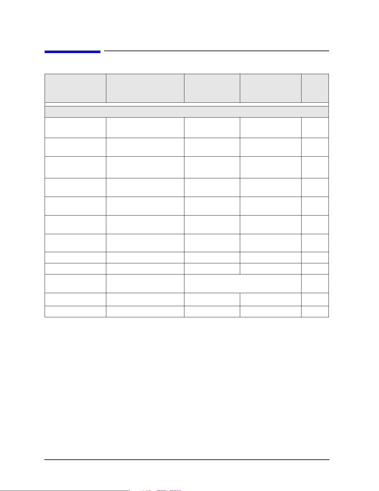
Required Service Test Equipment
Recommended
Equipment Critical Specifications
Test Instruments and Software
Model or Part
Number
Alternate Model
Number
Use
a
Frequency counter
Spectrum analyzer
Freq: 300 kHz to 9.0 GHz
Accuracy : ±0.5 ppm
Max Freq: >4 GHz
RBW: 300 Hz
Power meter Accuracy: ±0.0068 dB
Power sensor
Power sensor
Power sensor cable
(2 required)
Dynamic accuracy
test set
Freq: 300 kHz to 3.0 GHz
Range: –30 to +20 dBm
Freq: 3.0 to 9.0 GHz
Range: –30 to +20 dBm
Compatible with power
meter and power sensors.
None
53131A/32A
Opt 010,124
8561E
E4418B/19B
b
Opt G12 or H12
8482A
E4412A
b
53181A
Opt 010,124
856xE
Max freq: >4 GHz
E4418A/19A
c
None
None
P, A ,T
A,T
d
P, A ,T
P, A ,T
P, A ,T
11730A None P,A,T
Z5623A
Opt H01
None P
Digital voltmeter Resolution: 10 mV Any Any T
Oscilloscope Bandwidth: 100 MHz Any Any T
Printer N/A
Range calibrator N/A
Any printer with Microsoft®
Windows® 2000 driver
11683A None
P
P
c
Test software N/A N2721A None P
a. P = Performance tests, A = Adjustments, T = Troubleshooting, V = System Verification
b. When testing the E8356A, the E4418B power meter can be used and the E4412A power
sensor is not needed.
c. The accuracy of a standard E4418B or E4419B of ±0.02 dB is adequate for all tests except
“Dynamic Accuracy Test.” This test requires a power meter with Option G12 or H12 that
has been certified to a higher accuracy specification. If an Option G12 or H12 power
meter is not available, a test is provided on page 3-37 to verify the accuracy of a standard
power meter.
d. If an accurate measurement of the dynamic accuracy specification is not required, the
E4419A (or E4418A for testing the E8356A) can be used.
Microsoft® and Windows® 2000 are U.S. registered trademarks of Microsoft Corporation.
2-6 Service Guide E8356-90002
Page 25

PNA Series RF Network Analyzers General Product Information
E8356A, E8357A, E8358A Required Service Test Equipment
Equipment Critical Specifications
Recommended
Model or Part
Number
Alternate
Model
Number
Usea
Calibration and Verification Kits
Type-N calibration kit Refer to kit specifications 85032F
Type-N ECal module Refer to kit specifications 85092B
Type-N verification kit Refer to kit specifications 85055A
85033E
85093B
85053B
b
b
b
P, T, V
T, V
V
Cables
BNC cable (2 required) 50Ω, 24 inch 8120-1839 None A
Type-N RF cable
(2 required)
50Ω, 24 inch N6314A None P,A,V
GPIB cable N/A 10833A/B/C/D None P,A
Adapters and Accessories
c
Type-N (male to male) N/A 1250-0778 None P
Type-N (female to
female)
BNC (male) to
Type-N (female)
N/A 1250-0777 None P,A
N/A 1250-1477 None P,A
Type-N (female) to
3.5 mm (male)
N/A 1250-1750 None A,V
Tools and Static Safety Parts
Extender board N/A E8356-60021 None T
T-10 TORX driver 4, 7, 9 in-lb torque settings N/A N/A T,R
T-20 TORX driver 21 in-lb torque setting N/A N/A T,R
5/16 in open-end wrench 10, 21 in-lb torque settings N/A N/A T,R
Adjustable antistatic
wrist strap
Antistatic wrist strap
grounding cord (5 foot)
Static control table mat
and earth ground wire
N/A 9300-1367 None P,A,T
N/A 9300-0980 None P,A,T
N/A 9300-0797 None P,A,T
Floppy disks 3.5 inch Any None A
a. P = Performance tests, A = Adjustments, T = Troubleshooting, R = Repair,
V = System Verification
b. The Type-N calibration kit and verification kit are required for performance tests. These
3.5 mm kits can be used for system verification and analyzing the error terms.
c. Use of some adapters may be necessary if using the alternate 3.5 mm calibration or
verification kits.
Service Guide E8356-90002 2-7
Page 26

General Product Information PNA Series RF Network Analyzers
Agilent Support, Services, and Assistance
E8356A, E8357A, E8358A
Agilent Support, Services, and Assistance
Information on the following topics is included in this section.
• “Service and Support Options”
• “Calibration Options”
• “Contacting Agilent”
• “Shipping Your Analyzer to Agilent for Service or Repair”
Service and Support Options
The analyzer’s standard warranty is a one-year return to Agilent Technologies service
warranty.
NOTE
There are many other repair and calibration options available from the
Agilent Technologies support organization. These options cover a range of
service agreements with varying response times. Contact Agilent for
additional information on available service agreements for this product. Refer
to “Contacting Agilent” on page 2-9.
Calibration Options
Option R-50C-001, Commercial Calibration with Data
This option adds a calibration label, a calibration certificate, and the corresponding
calibration data on a 3.5-in floppy disk. This calibration conforms to ISO 9001.
This certificate and data can be obtained by sending your analyzer to Agilent for
calibration along with an order for R-50C-001. Refer to “Shipping Your Analyzer to Agilent
for Service or Repair”.
Option R-50C-002, Standards Compliant Calibration
This option adds calibration label, a calibration certificate, and the corresponding
calibration data, measurement uncertainties, and guardbands on all customer
specifications on a CD-ROM. This calibration conforms to ISO 17025 and ISO 9001.
This certificate and data can be obtained by sending your analyzer to Agilent for
calibration along with an order for R-50C-002. Refer to “Shipping Your Analyzer to Agilent
for Service or Repair”.
2-8 Service Guide E8356-90002
Page 27

PNA Series RF Network Analyzers General Product Information
E8356A, E8357A, E8358A Agilent Support, Services, and Assistance
Contacting Agilent
By internet, phone, or fax, get assistance with all your test and measurement needs.
Online assistance: www.agilent.com/find/assist
Americas
Brazil
(tel) (+55) 11 4197 3600
(fax) (+55) 11 4197 3800
Australia
(tel) 1800 629 485
(alt) 1800 143 243
(fax) 1800 142 134
Japan
(tel) 0120 421 345
(alt) (+81) 426 56 7832
(fax) 0120 421 678
Ta iw an
(tel) 0800 047 866
(alt) 00801 651 317
(fax) 0800 286 331
Austria
(tel) 0820 87 44 11*
(fax) 0820 87 44 22
France
(tel) 0825 010 700*
(alt) (+33) (0)1 6453 5623
(fax) 0825 010 701*
Canada
(tel) 877 894 4414
(fax) (+1) 905 282-6495
Asia Pacific and Japan
China
(tel) 800 810 0189
(alt) (+86) 10800 650 0021
(fax) 800 820 2816
Malaysia
(tel) 1800 888 848
(alt) 1800 828 848
(fax) 1800 801 664
Thailand
(tel) 1800 226 008
(alt) (+66) 2 268 1345
(fax) (+66) 2 661 3714
Belgium
(tel) (+32) (0)2 404 9340
(alt) (+32) (0)2 404 9000
(fax) (+32) (0)2 404 9395
Germany
(tel) 01805 24 6333*
(alt) 01805 24 6330*
(fax) 01805 24 6336*
Mexico
(tel) (+52) 55 5081 9469
(alt) 01800 5064 800
(fax) (+52) 55 5081 9467
Hong Kong
(tel) 800 930 871
(alt) (+852) 3197 7889
(fax) (+852) 2 506 9233
Singapore
(tel) 1800 375 8100
(alt) (+65) 6 375 8100
(fax) (+65) 6836 0252
Europe
Denmark
(tel) (+45) 7013 1515
(alt) (+45) 7013 7313
(fax) (+45) 7013 1555
Ireland
(tel) (+353) (0)1 890 924 204
(alt) (+353) (0)1 890 924 206
(fax)(+353) (0)1 890 924 024
United States
(tel) 800 829 4444
(alt) (+1) 303 662 3998
(fax) 800 829 4433
India
(tel) 1600 112 929
(fax) 000800 650 1101
South Korea
(tel) 080 769 0800
(alt) (+82) 2 2004 5004
(fax) (+82) 2 2004 5115
Finland
(tel) (+358) 10 855 2100
(fax) (+358) 10 855 2923
Israel
(tel) (+972) 3 9288 500
(fax) (+972) 3 9288 501
Italy
(tel) (+39) (0)2 9260 8484
(fax) (+39) (0)2 9544 1175
Spain
(tel) (+34) 91 631 3300
(alt) (+34) 91 631 3000
(fax) (+34) 91 631 3301
Switzerland (Italian)
(tel) 0800 80 5353 opt. 3*
(alt) (+39) (0)2 9260 8484
(fax) (+41) (0)22 567 5314
(tel) = primary telephone number; (alt) = alternate telephone number; (fax) = FAX number; * = in country number
Luxemburg
(tel) (+32) (0)2 404 9340
(alt) (+32) (0)2 404 9000
(fax) (+32) (0)2 404 9395
Sweden
(tel) 0200 88 22 55*
(alt) (+46) (0)8 5064 8686
(fax) 020 120 2266*
United Kingdom
(tel) (+44) (0)7004 666666
(alt) (+44) (0)7004 123123
(fax) (+44) (0)7004 444555
Netherlands
(tel) (+31) (0)20 547 2111
(alt) (+31) (0)20 547 2000
(fax) (+31) (0)20 547 2190
Switzerland (French)
(tel) 0800 80 5353 opt. 2*
(alt) (+33) (0)1 6453 5623
(fax) (+41) (0)22 567 5313
Russia
(tel) (+7) 095 797 3963
(alt) (+7) 095 797 3900
(fax) (+7) 095 797 3901
Switzerland (German)
(tel) 0800 80 5353 opt. 1*
(alt) (+49) (0)7031 464 6333
(fax) (+41) (0)1 272 7373
Service Guide E8356-90002 2-9
Page 28

General Product Information PNA Series RF Network Analyzers
Agilent Support, Services, and Assistance
E8356A, E8357A, E8358A
Shipping Your Analyzer to Agilent for Service or Repair
IMPORTANT
Agilent Technologies reserves the right to reformat or replace the internal
hard disk drive in your analyzer as part of its repair. This will erase all user
information stored on the hard disk. It is imperative, therefore, that you
make a backup copy of your critical test data located on the analyzer’s hard
disk before shipping it to Agilent for repair.
If you wish to send your network analyzer to Agilent Technologies for service or repair:
• Include a complete description of the service requested or of the failure and a
description of any failed test and any error message.
• Ship the analyzer using the original or comparable antistatic packaging materials.
• Contact Agilent for instructions on where to ship your analyzer. Refer to “Contacting
Agilent” on page 2-9.
2-10 Service Guide E8356-90002
Page 29

3 Tests and Adjustments
Service Guide E8356-90002 3-1
Page 30
Tests and Adjustments PNA Series RF Network Analyzers
Information in This Chapter
E8356A, E8357A, E8358A
Information in This Chapter
This chapter contains procedures to help you check, verify, and adjust your PNA series
RF network analyzer.
• The checks verify the operation of the assemblies in your analyzer.
• The verification compares the operation of your analyzer to a gold standard.
• The adjustments allow you to tune your analyzer for maximum response.
NOTE
A description of the performance tests in the Agilent N2721A software
package is included in this chapter. The Agilent N2721A software package
must be purchased separately.
Chapter Three at-a-Glance
Section Title Summary of Content Start Page
Items to consider or procedures to perform before
testing is begun:
• Verify the Operating Environment
Before You Begin
Before You Begin
• Protect Against Electrostatic Discharge (ESD)
• Allow the Analyzer to Warm Up
• Review the Principles of Connector Care
Descriptions of environmental conditions in which to
test the analyzer.
A review of the principles of connector care.
Descriptions of:
Page 3-4
Page 3-5
• System Specifications
About System
Ver i f i ca tion and
Performance Tests
ANSI/NCSL
Z540–1–1994
Ver i fica tion
Non-ANSI/NCSL
Z540–1–1994
Ver i fica tion
3-2 Service Guide E8356-90002
• Instrument Specifications
• System Verification Procedure
• Performance Tests
• Certificate of Calibration
The ANSI/NCSL Z540-1-1994 process of verifying your
analyzer.
The non-ANSI/NCSL Z540-1-1994 process of verifying
your analyzer.
Page 3-6
Page 3-8
Page 3-9
Page 31

PNA Series RF Network Analyzers Tests and Adjustments
E8356A, E8357A, E8358A Information in This Chapter
Section Title Summary of Content Start Page
Performing the operator’s check.
Preliminary Checks
System Verification
Performance Tests
(Agilent N2721A
Software Package)
Checking your test cables.
Page 3-10
Perform these checks before performing system
verification.
What the system verification does.
How to perform the verification test.
Page 3-20
How to interpret the results.
A brief summary of each performance test in the
Agilent N2721A software package:
• Source Power Accuracy Test
• Source Power Linearity Test
• Frequency Accuracy Test
• Trace Noise Test
1
• Receiver Compression Test
Page 3-30
• Noise Floor Test
• Calibration Coefficient Test
• System Crosstalk Test
• Dynamic Accuracy Test
Setups and procedures for adjusting your analyzer:
• Source Calibration Adjustment
• Receiver Calibration Adjustment
Adjustments
• LO Power Adjustment
• 10 MHz Frequency Reference Adjustment
• 3.8 GHz PMYO Frequency Adjustment
1. The Agilent N2721A software package must be purchased separately.
Page 3-42
Service Guide E8356-90002 3-3
Page 32

Tests and Adjustments PNA Series RF Network Analyzers
Before You Begin
E8356A, E8357A, E8358A
Before You Begin
Before checking, verifying, or adjusting the analyzer, refer to the following paragraphs to:
• make sure the operating environment is within its requirements
• make sure that proper electrostatic discharge (ESD) protection is provided
• make sure the analyzer has warmed up properly to achieve system stability
• review the principles of connector care
Verify the Operating Environment
Due to their operating specifications, the verification and calibration kit devices determine
your operating environment conditions. Open the calibration and verification kits and
place all the devices on top of the foam inserts so they will reach room temperature. As the
device dimensions change with temperature, their electrical characteristics change as well.
It is necessary to keep the environmental levels within the following limits:
• Temperature: +25 °C ±5 °C
Once the measurement calibration has been done, the ambient temperature must be
maintained to within ± 1 °C of the calibration temperature.
• Humidity: 0 to 80% at 26 °C maximum
Protect Against Electrostatic Discharge (ESD)
This is important. If not properly protected against, electrostatic discharge can seriously
damage your analyzer, resulting in costly repair.
CAUTION
To reduce the chance of electrostatic discharge, follow all of the
recommendations outlined in “Electrostatic Discharge Protection” on page
1-5, for all of the procedures in this chapter.
Allow the Analyzer to Warm Up
NOTE
To achieve the maximum system stability, allow the analyzer to warm up for
at least 90 minutes.
3-4 Service Guide E8356-90002
Page 33

PNA Series RF Network Analyzers Tests and Adjustments
E8356A, E8357A, E8358A Before You Begin
Review the Principles of Connector Care
Proper connector care and connection technique are critical for accurate and repeatable
measurements. Refer to Table 3-1 for tips on connector care.
Prior to making connections to your analyzer, carefully review the information about
inspecting, cleaning, and gaging connectors. Refer to the calibration kit documentation for
detailed connector care information.
For course numbers about additional connector care instruction, contact Agilent
Technologies. Refer to “Contacting Agilent” on page 2-9.
Table 3-1 Connector Care Quick Reference Guide
Handling and Storage
Do • Keep connectors clean Do Not • Touch mating-plane surfaces
• Extend sleeve or connector nut • Set connectors contact-end down
• Use plastic end-caps during storage
Visual Inspection
Do • Inspect all connectors carefully Do Not • Use a damaged connector - ever
• Look for metal particles, scratches,
and dents
Connector Cleaning
Do • Try compressed air first Do Not • Use any abrasives
• Use isopropyl alcohol • Get liquid into plastic support
• Clean connector threads
Gaging Connectors
Do • Clean and zero the gage before use Do Not • Use an out-of-specification
• Use the correct gage type
• Use correct end of calibration block
• Gage all connectors before first use
Making Connections
Do • Align connectors carefully Do Not • Apply bending force to connection
• Make preliminary connection contact
lightly
• Turn only the connector nut • Twist or screw any connection
• Use a torque wrench for final
connection
beads
connector
• Over tighten preliminary
connection
• Tighten past torque wrench
“break” point
Service Guide E8356-90002 3-5
Page 34

Tests and Adjustments PNA Series RF Network Analyzers
About System Verification and Performance Tests
E8356A, E8357A, E8358A
About System Verification and Performance Tests
The performance of the network analyzer is specified in two ways: system specifications,
and instrument specifications. Respectively, the analyzer’s conformance to these
specifications is verified in two ways: system verification, and performance tests.
System Specifications
System specifications specify warranted performance of the measurement system when
making error-corrected measurements. The measurement system includes the analyzer,
test cables, and calibration kit.
The analyzer's system specifications are described in the Agilent PNA Series Network
Analyzer Data Sheet and also in the analyzer’s on-line help system.
System specifications are included in section titled “Corrected System Performance.”
System specifications are expressed in two ways:
• residual errors of the measurement system
• graphs of measurement uncertainty versus reflection and transmission coefficients
System specifications are applicable when the measurement system is used to make
error-corrected measurements.
System specifications are verified in one of the following ways:
• Complete the system verification procedure using a certified verification kit, or
• Complete all of the performance tests and certify (or recertify) the calibration kit that
will be used for future measurements. This alternative verifies both the system
specifications and the instrument specifications for the analyzer.
Instrument Specifications
Instrument specifications specify the network analyzer's uncorrected measurement port
characteristics and its output and input behavior.
The analyzer's instrument specifications are described in the Agilent PNA Series Network
Analyzer Data Sheet and also in the analyzer’s on-line help system. The sections that
describe instrument specifications are titled:
• “Uncorrected System Performance”
•“Test Port Output”
•“Test Port Input”
These specifications apply when the analyzer is used to make measurements other than
error-corrected measurements. An example would be the measurement of amplifier gain
compression.
Performance tests are used to confirm that the analyzer meets the instrument
specifications.
3-6 Service Guide E8356-90002
Page 35

PNA Series RF Network Analyzers Tests and Adjustments
E8356A, E8357A, E8358A About System Verification and Performance Tests
System Verification Procedure
The system verification procedure tests the network analyzer measurement system, as
defined previously, against the system specifications. If confirmation is successful, the
measurement system is capable of making measurements to the accuracy specified by the
graphs of measurement uncertainty.
An illustrated outline of the system verification procedure:
• for ANSI/NCSL Z540-1-1994 verification, is shown in Figure 3-1 on page 3-8.
• for non-ANSI/NCSL Z540-1-1994 verification, is shown in Figure 3-2 on page 3-9.
NOTE
Calibration kits are different from verification kits. Calibration kits are used
to determine the systematic errors of a network analyzer measurement
system. Verification kits are used to confirm system specifications and are not
used to generate error correction.
Performance Tests
Performance tests are used to confirm analyzer performance against the instrument
specifications. If confirmation is successful, the analyzer meets the instrument
specifications.
If the calibration kit to be used for measurements is also certified, successful completion of
the performance tests also ensures that the network analyzer measurement system meets
the system specifications.
Certificate of Calibration
Agilent Technologies will issue a certificate of calibration for the product upon successful
completion of system verification or completion of the performance tests. The certificate of
calibration will include a “System Attachment” if the system verification procedure is used
to confirm the system specifications. If the performance tests are used to confirm
instrument specifications, the certificate of calibration will not include a system
attachment. The equipment and measurement standards used for the tests must be
certified and must be traceable to recognized standards.
NOTE
Service Guide E8356-90002 3-7
If you have a measurement application that does not use all of the
measurement capabilities of the analyzer, you may ask your local Agilent
Technologies service office to verify only a subset of the specifications.
However, this creates the possibility of making inaccurate measurements if
you then use the analyzer in an application requiring additional capabilities.
Page 36

Tests and Adjustments PNA Series RF Network Analyzers
ANSI/NCSL Z540– 1– 1994 Verification
E8356A, E8357A, E8358A
ANSI/NCSL Z540–1–1994 Verification
To meet the criteria for ANSI/NCSL Z540-1-1994, perform the preliminary checks and
either system verification or performance tests without stopping to repair or adjust
to Figure 3-1 for test flow. Print data at the completion of all the tests, even if you are
aware that the analyzer did not pass. If there is a failure, complete the verification before
you troubleshoot, repair, and adjust. After the failure has been corrected, repeat the entire
system verification or performance tests and generate a new set of data.
Figure 3-1 ANSI/NCSL Z540–1–1994 Test Path Verification Flowchart
1
. Refer
1. Stop only in case of a catastrophic failure or cable connector damage
3-8 Service Guide E8356-90002
Page 37

PNA Series RF Network Analyzers Tests and Adjustments
E8356A, E8357A, E8358A Non-ANSI/NCSL Z540–1– 1994 Verification
Non-ANSI/NCSL Z540–1–1994 Verification
For non-ANSI/NCSL Z540-1-1994, perform the preliminary checks and either the system
verification or performance tests while stopping to troubleshoot. Refer to Figure 3-2 for test
flow. Troubleshoot and repair the first problem encountered without continuing to other
tests. After you troubleshoot, repair, and adjust, repeat the last failed portion and generate
a new set of data. Print out the system verification results or complete the performance
test record as the analyzer passes each test.
Figure 3-2 Non–ANSI/NCSL Z540–1–1994 Test Path Verification Flowchart
Service Guide E8356-90002 3-9
Page 38

Tests and Adjustments PNA Series RF Network Analyzers
Preliminary Checks
E8356A, E8357A, E8358A
Preliminary Checks
Preliminary checks include the following:
• “The Operator’s Check” on page 3-10
The operator’s check tests the network analyzer’s basic functionality of the source,
switch, step attenuators, and receivers.
• “The Test Port Cable Checks” on page 3-13
The test port cable checks are not required, but are recommended to verify the
performance of the test port cables before performing the verification test.
The Operator’s Check
NOTE
The operator’s check is a software driven test that checks the basic operation of the
assemblies in the Port 1 and Port 2 paths. By performing the operator’s check, the
following is determined:
• operation of the transfer switch (switch repeatability check)
• phase-lock capability across the entire frequency band (switch repeatability check)
• function of the four receivers (switch repeatability check)
• operation of the step attenuators (attenuator range check)
• receivers’ linearity (attenuator range check)
Switch Repeatability Check
The check performs a reflection measurement of a short and stores the resulting trace in
memory. The transfer switch is toggled to the opposite port and back, and then another
reflection measurement is made. The difference between the stored trace and the return
trace is the switch repeatability. This test also checks the phase lock across the entire
frequency band and operation of all four receivers.
Attenuator Range Check
To achieve the maximum system stability, allow the analyzer to warm up for
at least 90 minutes before performing the Operator’s Check.
This check performs a reflection measurement of a short and stores the resulting trace in
memory. As the internal attenuator is switched in 10 dB steps over its 70 dB range,
reflection measurements are made and compared with the stored trace. The resulting
measurements must fall within a limit testing window to pass the test. The window size is
based on source and receiver specifications. By performing the Port 1 and Port 2 tests,
rough checks of the linearity for all four receivers (from 0 dB to 70 dB) are verified and
operation of the attenuator is verified.
3-10 Service Guide E8356-90002
Page 39

PNA Series RF Network Analyzers Tests and Adjustments
E8356A, E8357A, E8358A Preliminary Checks
Accessories Used in the Operator’s Check
Equipment Type Par t Number
Male short, type-N
1. Alternate choice: 3.5 mm short from 3.5 mm 85033E calibration kit and type-N to 3.5 mm
adapter.
1
85032-60016 (from the 85032F calibration kit)
Performing the Operator’s Check
1. From the System menu, point to Service, and then click Operator’s Check.
2. In the Operator’s Check dialog box (refer to Figure 3-3), click Configure, and then
select either Automatic, to run through the test without stopping, or Prompted, to
pause at each step in the test process.
3. To check Port 1, click Start--Port 1 or to check Port 2, click Start--Port 2.
4. The test will prompt you to connect the short.
5. The result of the operator’s check will be shown as a PASS or FAIL next to the test.
Figure 3-3 Operator’s Check Dialog Box
If the Operator’s Check Fails
1. Clean the test ports, shorts, and adapters. Torque to specification. Repeat the check.
2. If the check still fails, suspect a faulty component:
• A repeated failure in the switch repeatability for both the Port 1 and Port 2 checks
indicates a faulty A22 RF switch splitter. Refer to “Removing and Replacing the A22
Switch Splitter Assembly” on page 7-32.
Service Guide E8356-90002 3-11
Page 40

Tests and Adjustments PNA Series RF Network Analyzers
Preliminary Checks
E8356A, E8357A, E8358A
• A repeated failure in any of the ranges of the attenuator check indicates a faulty step
attenuator.
— If the Port 1 check fails, the A25 step attenuator may be faulty.
— If the Port 2 check fails, the A26 step attenuator may be faulty.
Refer to “Removing and Replacing the A25 and A26 70 dB Step Attenuators” on
page 7-36.
•If all ranges of the attenuator check fail, suspect a loose connection on the step
attenuator control cable.
— If the Port 1 check fails, check the A25 step attenuator cable.
— If the Port 2 check fails, check the A26 step attenuator cable.
3-12 Service Guide E8356-90002
Page 41

PNA Series RF Network Analyzers Tests and Adjustments
E8356A, E8357A, E8358A Preliminary Checks
The Test Port Cable Checks
A faulty test port cable can cause a failure in the verification test. The following checks are
not required, but are recommended to verify the performance of the test port cable.
• “Cable Return Loss Check” on page 3-14
• “Cable Insertion Loss Check” on page 3-15
• “Cable Magnitude and Phase Stability Check” on page 3-16
• “Cable Connector Repeatability Check” on page 3-18
Accessories Used in the Test Port Cable Checks
Equipment Type Par t Number Alternate Part Number
RF cable, type-N N6314A See “Cable Substitution” on page 3-23.
Calibration kit 85032F (type-N)
1. Use of this alternate will require the use of adapters.
85033E (3.5 mm)
1
Service Guide E8356-90002 3-13
Page 42

Tests and Adjustments PNA Series RF Network Analyzers
Preliminary Checks
E8356A, E8357A, E8358A
Cable Return Loss Check
1. Press Preset.
2. Perform a one-port calibration on Port 1, 1-Port Reflection. Refer to the embedded help
in the analyzer if necessary.
3. Connect the test port cable to Port 1. Connect a broadband load to the other end of the
cable. Tighten to the specified torque for the connector type.
The analyzer now displays the return loss of the cable.
4. From the Marker menu, click Marker Search. In the Marker Search dialog box, in the
Search Type box, make sure Maximum is selected. Click Execute, and then click OK.
5. The marker annotation on the screen indicates the worst case return loss. Refer to the
cable manual to see if it meets the return loss specification. For an example of a typical
return loss measurement, see Figure 3-4.
Figure 3-4 Typical Cable Return Loss Response
If the Cable Return Loss Check Fails
1. Clean the cable and devices and torque to specification. Repeat the check.
2. If the check still fails, the cable should be repaired or replaced.
3-14 Service Guide E8356-90002
Page 43

PNA Series RF Network Analyzers Tests and Adjustments
E8356A, E8357A, E8358A Preliminary Checks
Cable Insertion Loss Check
1. Keep the test port cable connected to Port 1.
2. Connect a short to the end of the cable.
3. From the Marker menu, click Marker Search. In the Marker Search dialog box, in the
Search Type box, select Minimum. Click Execute, and then click OK.
4. The displayed response is twice the actual loss. To get the actual worst case insertion
loss, divide the value at the marker annotation by two. Refer to the cable manual to see
if it meets the insertion loss specification. For an example of a typical insertion loss
measurement, see Figure 3-5.
Figure 3-5 Typical Cable Insertion Loss Response
If the Cable Insertion Loss Check Fails
1. Clean the cable and devices and torque to specification. Repeat the check.
2. If the check still fails, the cable should be repaired or replaced.
Service Guide E8356-90002 3-15
Page 44

Tests and Adjustments PNA Series RF Network Analyzers
Preliminary Checks
E8356A, E8357A, E8358A
Cable Magnitude and Phase Stability Check
1. Keep the cable connected to Port 1, then connect a short to the end of the cable.
2. Press Preset.
3. On the Trace menu, click New Trace. In the New Trace dialog box, click the S11 box,
and then click OK.
4. On the Trace menu, click Format. In the Format dialog box, click Phase, and then click
OK.
5. On the Channel menu, click Average. In the Average dialog box, click the Average ON
check box. In the Average Factor box, type 50 or click the arrows to select 50, and then
click OK.
6. To provide a good reference, hold the test cable in a straight line perpendicular to the
front panel of the network analyzer.
7. On the Channel menu, click Restart Avg.
8. Wait for the analyzer to average the measurement 50 times (approximately two
seconds).
9. To normalize the data trace:
a. On the Trace menu, click Math/Memory.
b. In the Math/Memory dialog box, click the Data->Memory button.
c. In the Data Math list, select Data/Memory.
d. Under Trace View Options, make sure Data Trace is selected.
e. Click OK
10. Slowly make a 180 degree bend in the middle of the cable and hold it in that position.
11. For each trace: On the Scale menu, set the Scale Per Division for optimum viewing as
shown in Figure 3-6.
12. Place a marker on the largest deflection that goes above the reference line and is
within the cable’s specified frequency range. For a typical response of cable magnitude
and phase stability, see Figure 3-6.
13. Place a marker on the largest deflection that goes below the reference line and is
within the cable’s specified frequency range.
In this S
measurement, the displayed trace results from energy being propagated
11
down the cable and reflected back from the short. Therefore, the measured deflection
value must be divided in half to reach the correct value.
3-16 Service Guide E8356-90002
Page 45

PNA Series RF Network Analyzers Tests and Adjustments
E8356A, E8357A, E8358A Preliminary Checks
Figure 3-6 Typical Cable Magnitude and Phase Stability Response
If the Cable Magnitude and Phase Stability Check Fails
1. Clean the cable and devices and torque to specification. Repeat the check.
2. If the check still fails, the cable should be repaired or replaced.
Service Guide E8356-90002 3-17
Page 46

Tests and Adjustments PNA Series RF Network Analyzers
Preliminary Checks
E8356A, E8357A, E8358A
Cable Connector Repeatability Check
NOTE
The connector repeatability measurement should be done at the test port as
well as at the end of the test port cable.
1. With the test port cable still connected to Port 1, connect a broadband load to the other
end of the cable.
2. Press Preset.
3. On the Channel menu, click Average. In the Average dialog box, click the Average ON
check box. In the Average Factor box, type 100 or click the arrows to select 100. Click
OK.
4. Wait for the analyzer to average the measurement 100 times (approximately five
seconds).
5. To normalize the data trace:
a. On the Trace menu, click Math/Memory.
b. In the Math/Memory dialog box, click the Data->Memory button.
c. In the Data Math list, select Data/Memory.
d. Under Trace View Options, make sure Data Trace is selected.
e. Click OK
6. To adjust the display scale:
a. On the Scale menu, click Scale.
b. In the Scale Per Division box, click the arrow to select 0.5 dB.
c. In the Level box under Reference click the arrow to select 0 dB.
d. Click OK.
7. Disconnect and then reconnect the cable to the test port. Tighten the connection to the
specified torque for the connector type.
8. On the Channel menu, click Restart Avg.
9. Look at the trace for spikes or modes.
10. To re-normalize the data trace of the reconnected cable:
a. On the Trace menu, click Math/Memory.
b. In the Math/Memory dialog box, click the Data->Memory button.
c. Click OK.
11. Repeat steps 7 through 9 at least three times to look for modes. (Modes appear when a
harmonic of the source fundamental frequency is able to propagate through the cable
or connector). It is helpful to print a plot of the trace each time to compare several
connections. If any mode appears each time the cable is connected and reconnected,
measurement integrity will be affected.
For a typical response of cable connector repeatability, see Figure 3-7.
3-18 Service Guide E8356-90002
Page 47

PNA Series RF Network Analyzers Tests and Adjustments
E8356A, E8357A, E8358A Preliminary Checks
12. For the Port 2 Check, connect the cable to Port 2 and repeat steps 2 through 11.
Figure 3-7 Typical Cable Connector Repeatability Response
If the Cable Connector Repeatability Check Fails
1. Clean the cable and devices, and torque to specification. Repeat the check.
2. If the check still fails, the cable should be repaired or replaced.
Service Guide E8356-90002 3-19
Page 48

Tests and Adjustments PNA Series RF Network Analyzers
System Verification
E8356A, E8357A, E8358A
System Verification
System verification is used to verify system-level, error-corrected uncertainty limits for
network analyzer measurements. The verification procedure is automated and is
contained in the firmware of the analyzer.
The device data provided with the verification kit has a traceable path to a national
standard. The difference between the supplied traceable data and the measured data must
fall within the total uncertainty limits at all frequencies for the system verification to pass.
The total measurement uncertainty limits for the system verification are the sum of the
factory measurement uncertainties for the verification devices and the uncertainties
associated with the system being verified. You can determine your system measurement
uncertainty limits by referring to the analyzer embedded on-line help.
IMPORTANT
Passing this system verification does not guarantee that the analyzer meets
all of its performance specifications. However, it does show that the network
analyzer being verified measures the same devices with the same results as a
factory system which has had all of its specifications verified and its total
measurement uncertainty minimized.
What the System Verification Verifies
The system verification procedure verifies proper operation of the:
• network analyzer
• calibration kit
• test port cables
NOTE
Additional equipment or accessories used with the above system are not
verified by system verification.
3-20 Service Guide E8356-90002
Page 49

PNA Series RF Network Analyzers Tests and Adjustments
E8356A, E8357A, E8358A System Verification
Measurement Uncertainty
Measurement uncertainty is defined as the sum of:
• the residual systematic (repeatable) errors, and
• the random (non-repeatable) errors
in the measurement system after calibration.
The systematic errors are:
•directivity,
• source match,
• load match,
• reflection and transmission frequency tracking, and
• isolation (crosstalk).
The random errors include:
•noise,
•drift,
• connector repeatability, and
• test cable stability.
A complete description of system errors and how they affect measurements is provided in
the analyzer’s on-line embedded help.
Any measurement result is the vector sum of the actual test device response plus all error
terms. The precise effect of each error term depends on its magnitude and phase
relationship to the actual test device response. When the phase of an error response is not
known, phase is assumed to be worst-case (−180° to +180°). Random errors such as noise
and connector repeatability are generally combined in a root-sum-of-the-squares (RSS)
manner.
Service Guide E8356-90002 3-21
Page 50

Tests and Adjustments PNA Series RF Network Analyzers
System Verification
E8356A, E8357A, E8358A
Measurement Traceability
To establish a measurement traceability path to a national standard for a network
analyzer system, the overall system performance is verified through the measurement of
devices that have a traceable path. This is accomplished by measuring the devices in an
Agilent verification kit.
The measurement of the devices in the verification kit has a traceable path because the
factory system that measured the devices is calibrated and verified by measuring
standards that have a traceable path to the National Institute of Standards and
Technology (NIST) (see Figure 3-8). This chain of measurements defines how the
verification process brings traceability to the network analyzer system.
Figure 3-8 NIST Traceability Path for Calibration and Verification Standard
3-22 Service Guide E8356-90002
Page 51

PNA Series RF Network Analyzers Tests and Adjustments
E8356A, E8357A, E8358A System Verification
Performing System Verification
The following verification procedure is automated by the analyzer firmware. For each
verification device, the analyzer reads a file from the verification disk and sequentially
measures the magnitude and phase for all four S-parameters.
NOTE
Although the performance for all four S-parameters are measured, the S11
and S
phase uncertainties for the attenuators and airlines are less
22
important for verifying system performance. Therefore, the limit lines will
not appear on the printout.
Equipment Used in the System Verification Procedure
Equipment Type
Calibration kit or
ECal module
Verification kit 85055A (type-N) 85053B (3.5 mm)
RF cable N6314A (type-N) See “Cable Substitution” below.
1. Use of these alternates may require the use of adapters.
Part Number
85032F (type-N)
85092B (type-N)
Alternate Part Number
85033E (3.5 mm)
85093B (3.5 mm)
1
Cable Substitution
The test port cables specified for the network analyzer system have been characterized for
connector repeatability, magnitude and phase stability with flexing, return loss, insertion
loss, and aging rate. Since test port cable performance is a significant contributor to the
system performance, cables of lower performance will increase the uncertainty of your
measurement. Refer to the plots in the cable tests (earlier in this chapter) that show the
performance of good cables. It is highly recommended that the test port cables to be
regularly tested.
If the system verification is performed with a non-Agilent cable, ensure that the cable
meets or exceeds the specifications for the N6314A type-N cable. Refer to the N6314A
user’s guide for specifications.
Calibration Kit Substitution
Non-Agilent calibration kits are not recommended nor supported.
Service Guide E8356-90002 3-23
Page 52

Tests and Adjustments PNA Series RF Network Analyzers
System Verification
E8356A, E8357A, E8358A
Precautions for Handling Airlines
The verification kit includes airlines. Follow the steps below to ensure good measurement
techniques.
• Be very careful not to drop the airline’s center or outer conductor. Irreparable damage
will result if these devices are dropped.
• During this procedure, you will be touching the exposed center conductor of the test
port and the center conductor of the airline.
— Observe proper ESD procedures.
— Clean your hands or wear gloves; skin oils will cause a change in electrical
performance.
• Refer to Figure 3-9 and Figure 3-10 for connection procedures.
Figure 3-9 Aligning the Center Conductor
Figure 3-10 Torquing the Connection
3-24 Service Guide E8356-90002
Page 53

PNA Series RF Network Analyzers Tests and Adjustments
E8356A, E8357A, E8358A System Verification
System Verification Procedure
1. Connect a cable to Port 1 on the analyzer as shown in Figure 3-11. If you desire printed
test outputs, connect a printer to the analyzer. For the printer, ensure that the correct
driver is loaded and the printer is defined as the default printer. Refer to the embedded
help in the analyzer for printer setup. Let the analyzer warm up for at least 90 minutes.
Figure 3-11 System Verification Test Setup
2. Insert the verification kit disk into the analyzer disk drive.
3. On the System menu, point to Service, and then click System Verification. The System
Verification dialog box is displayed; refer to Figure 3-12.
Figure 3-12 System Verification Dialog Box
Service Guide E8356-90002 3-25
Page 54

Tests and Adjustments PNA Series RF Network Analyzers
System Verification
E8356A, E8357A, E8358A
4. In the Calibration Kit box, select the calibration kit that is being used by clicking on it.
The corresponding verification kit to use is selected for you and displayed in the
Verification Kit box. Refer to Figure 3-12.
5. Under Printer Output, click one of the following options. Refer to Figure 3-12.
• None: No printout of results.
• Tabul a r Data : Prints the verification data in tabular form which includes measured
data and uncertainty limits. For an example, refer to Figure 3-15 on page 3-28.
• Measurement Plots: Prints the verification data in graphical form. The graphical
form includes the measured data trace, factory supplied data trace, and uncertainty
limits. For an example, refer to Figure 3-16 on page 3-29.
• Both: Prints the verification data in both formats.
NOTE
For printed output, it is assumed that the printer has been tested and the
Windows 2000 driver is installed for the printer that is being used. The
system verification test prints to the printer that has been designated as the
default printer. (On the Windows Desktop display, click on My Computer,
Control Panel, and then Printers to verify the printer setup.)
6. Click Run.
7. Follow the instructions on the analyzer for performing a full 2-port calibration.
8. After completion of the full 2-port calibration, follow the instructions on the analyzer for
performing the system verification.
For the system verification, insert the devices as shown in Figure 3-13.
Figure 3-13 System Verification Device Connections
3-26 Service Guide E8356-90002
Page 55

PNA Series RF Network Analyzers Tests and Adjustments
E8356A, E8357A, E8358A System Verification
If the System Fails the Verification Test
IMPORTANT
Inspect all connections. Do not remove the cable from the analyzer test port.
This will invalidate the calibration that you performed earlier.
1. Disconnect and clean the device that failed the verification test.
2. Reconnect the device making sure that all connections are torqued to the proper
specifications.
3. Measure the device again.
4. If the analyzer still fails the test, check the measurement calibration by viewing the
error terms as described in “Accessing Error Terms” on page A-6.
5. Refer to Figure 3-14 for additional troubleshooting steps.
Figure 3-14 System Verification Failure Flowchart
Service Guide E8356-90002 3-27
Page 56

Tests and Adjustments PNA Series RF Network Analyzers
System Verification
E8356A, E8357A, E8358A
Interpreting the Verification Results
Figure 3-15 shows an example of typical verification results with Tabul ar Dat a selected in
the Printer Output area of the System Verification dialog box.
At the top of the printed output is the name of the device, the serial number of the device,
and the date tested.
Each S-parameter measurement result is printed with frequency tested, lower and upper
limit lines, the measured data, and the result of the test.
Figure 3-15 Example of Printed Tabular Verification Results
Sys Ver -- 20 dB attenuator magnitude results, Serial #00810 -- 6 Sep 2000
S11 Results
Frequency Lower Limit Measured Data Upper Limit Result
0.3 MHz 0.0048 Units 0.0090 Units 0.0139 Units PASS
100 0.0046 0.0091 0.0137 PASS
200 0.0042 0.0092 0.0134 PASS
300 0.0040 0.0091 0.0133 PASS
400 0.0038 0.0089 0.0131 PASS
500 0.0036 0.0087 0.0129 PASS
600 0.0034 0.0085 0.0127 PASS
700 0.0031 0.0082 0.0125 PASS
800 0.0029 0.0080 0.0122 PASS
900 0.0026 0.0079 0.0119 PASS
1000 0.0023 0.0075 0.0117 PASS
1100 0.0020 0.0072 0.0114 PASS
1200 0.0017 0.0068 0.0111 PASS
1300 0.0013 0.0064 0.0107 PASS
1400 -0.0006 0.0059 0.0118 PASS
1500 -0.0011 0.0052 0.0113 PASS
1600 -0.0015 0.0044 0.0108 PASS
1700 -0.0020 0.0038 0.0103 PASS
1800 -0.0026 0.0032 0.0097 PASS
1900 -0.0031 0.0024 0.0091 PASS
2000 -0.0036 0.0019 0.0085 PASS
2100 -0.0045 0.0016 0.0082 PASS
2200 -0.0050 0.0018 0.0077 PASS
2300 -0.0054 0.0023 0.0073 PASS
2400 -0.0052 0.0031 0.0075 PASS
2500 -0.0048 0.0039 0.0080 PASS
2600 -0.0040 0.0050 0.0087 PASS
2700 -0.0032 0.0060 0.0094 PASS
2800 -0.0024 0.0071 0.0103 PASS
2900 -0.0014 0.0082 0.0113 PASS
3000 -0.0004 0.0095 0.0124 PASS
Overall PASS/FAIL result for entire frequency range = PASS
3-28 Service Guide E8356-90002
Page 57

PNA Series RF Network Analyzers Tests and Adjustments
E8356A, E8357A, E8358A System Verification
Figure 3-16 shows an example of typical verification results with Measurement Plots
selected in the Printer Output area of the System Verification windows. The printed
graphical results show the following:
• the name of the device measured
• the serial number of the device
• the parameters measured
• Results of the measurements. Labeled as A in Figure 3-16.
• Data measured at the factory from the verification kit. Labeled as B in Figure 3-16.
• Upper and lower limit points as defined by the total system uncertainty system.
Labeled as C in Figure 3-16.
Figure 3-16 Example of Printed Graphical Verification Results
Service Guide E8356-90002 3-29
Page 58

Tests and Adjustments PNA Series RF Network Analyzers
Performance Tests (Agilent N2721A Software Package)
E8356A, E8357A, E8358A
Performance Tests (Agilent N2721A Software Package)
The Agilent N2721A software package verifies the electrical performance of your E8364A
PNA series microwave network analyzer. The software automatically configures your
analyzer to execute the performance tests. The N2721A software package is not included
with the analyzer; it must be ordered separately. The model numbers of the equipment
used are specified under “Required Service Test Equipment” on page 2-6.
There are nine tests in the software package:
• Source Power Accuracy Test
• Source Power Linearity Test
• Frequency Accuracy Test
• Trace Noise Test
• Receiver Compression Test
• Noise Floor Test
• Calibration Coefficient Test
• System Crosstalk Test
• Dynamic Accuracy Test
Source Power Accuracy Test
Function of the Test: To confirm the accuracy of the source output power of your network
analyzer over its full frequency range.
Specification Tested: Test Port Output–Power Level Accuracy
Equipment Used: A power meter, power sensors, and adapters.
Description of the Test:
1. The analyzer’s output power level is set to 0 dBm.
2. A power sensor is connected to Port 1.
3. The output power is measured at hundreds of CW frequencies across the analyzer’s
frequency range and the values compared to the setting of 0 dBm.
If the Analyzer Fails this Test:
• Perform the “Source Calibration Adjustment” on page 3-43 and repeat this test.
• If the analyzer still fails this test, replace the source assembly and repeat this test.
Refer to “Removing and Replacing the A12 Source Assembly” on page 7-20.
3-30 Service Guide E8356-90002
Page 59

PNA Series RF Network Analyzers Tests and Adjustments
E8356A, E8357A, E8358A Performance Tests (Agilent N2721A Software Package)
Source Power Linearity Test
Function of the Test: To verify that the power level is linear over the analyzer’s
frequency range and to check the linearity of the automatic leveling control (ALC).
Specification Tested: Power Sweep Range and Power Level Linearity
Equipment Used: A test cable. (And a 20 dB pad if the analyzer does not have an internal
step attenuator.)
Description of the Test:
1. The Port 2 receiver is used to test Port 1. The receiver linearity is the standard against
which the source linearity is checked.
2. A test cable is connected between Port 1 and Port 2 with 20 dB of attenuation in series
with the cable. This can be done with an internal step attenuator or an external 20 dB
pad. This attenuation ensures that the receiver remains in its linear range.
3. The analyzer is set to 25 different points across its frequency range.
4. At each frequency point, the output power level on Port 2 is set to 0.000 dBm and the
power is measured to establish a reference, P
reference
.
5. The source setting is then stepped from −15 to +10 dBm in 1 dB steps and the power is
measured, P
measured
, at each setting.
6. The non-linearity in dB at each frequency point is calculated as:
(P
measured
− P
reference
) − (source setting)
If the Analyzer Fails this Test:
• Perform the “Source Calibration Adjustment” on page 3-43 and repeat this test.
• If the analyzer still fails this test, replace the source assembly and repeat this test.
Refer to “Removing and Replacing the A12 Source Assembly” on page 7-20.
Frequency Accuracy Test
Function of the Test: To verify the frequency accuracy and range of the analyzer’s source
output.
Specification Tested: Test Port Output–CW Accuracy
Equipment Used: A frequency counter, a test cable, and adapters.
Description of the Test:
1. Port 1 is connected to a frequency counter.
2. A series of frequencies across the band are checked.
If the Analyzer Fails this Test:
• Verify the accuracy of the 10 MHz OCXO by connecting a frequency counter to the
rear-panel 10 MHz REF OUT.
• If the 10 MHz reference is off by more than 10 Hz, perform the “10 MHz Frequency
Reference Adjustment” on page 3-47 and also the “3.8 GHz PMYO Frequency
Adjustment” on page 3-48 and repeat this test.
Service Guide E8356-90002 3-31
Page 60

Tests and Adjustments PNA Series RF Network Analyzers
Performance Tests (Agilent N2721A Software Package)
E8356A, E8357A, E8358A
Trace Noise Test
Function of the Test: To measure the stability of a signal in the internal source and
receiver system of your analyzer.
Specification Tested: Test Port Input–Trace Noise Magnitude and Trace Noise Phase
Equipment Used: A test cable.
Description of the Test:
1. Port 1 and Port 2 are connected with a test cable.
2. The analyzer is set to a series of CW frequencies across its frequency range.
3. Magnitude and phase are measured at each frequency at both 1 kHz and 10 kHz IF
bandwidths, in both directions.
4. All measurements are made at a nominal power level of 0 dBm and with 201 points per
sweep.
If the Analyzer Fails this Test:
• Repeat this test. It is unlikely for the analyzer to fail this test without a complete
failure of the network analyzer system.
• If the analyzer still fails this test, perform the “Receiver Calibration Adjustment” on
page 3-44 and repeat this test.
Receiver Compression Test
Function of the Test: To measure the compression at the analyzer’s specified maximum
power level for the receivers.
Specification Tested: Test Port Input–Maximum Test Port Input Level
Equipment Used: The compression test set (Z5623A Option K01), a power meter, power
sensors, two test cables, and a calibration kit. (And 10-dB and 20-dB pads if the analyzer
does not have an internal step attenuator.)
Description of the Test:
1. All measurements are made with a 50 kHz IF bandwidth and 201 points per sweep.
2. The measurements are made separately on each port.
3. The analyzer is set to various CW frequencies across the range of the analyzer.
4. A power sensor is connected to the “signal source point” to be used to test the port. The
“signal source point” may be either the port connector itself, when a short is used, or
the end of the test cable, when the compression test set is used to source the test signal.
5. The analyzer source output level is adjusted to create the maximum power level
specified for the receiver.
6. The power sensor is disconnected and the “signal source point” is connected to the port
to be tested.
7. The absolute log magnitude value (dBm) for the reference channel on the source port is
read.
3-32 Service Guide E8356-90002
Page 61

PNA Series RF Network Analyzers Tests and Adjustments
E8356A, E8357A, E8358A Performance Tests (Agilent N2721A Software Package)
8. The log magnitude ratioed measurement using the receiver under test is read: (Pa).
9. The source output level is adjusted to decrease the output by 15 dB.
10. The log magnitude ratioed measurement using the receiver under test is read: (P
).
b
11. Attenuation of 20 dB is introduced between the source and receiver. This can be done
with an internal step attenuator, an external 10 dB pad (if a short is being used to
reflect the signal back into the port), or an external 20 dB pad (if the signal source is
the compression test set).
12. The log magnitude ratioed measurement using the receiver under test is read: (P
).
c
13. The source output level is adjusted to produce a reading of Pref (within ±0.03 dBm) for
the reference channel on the source port.
14. The log magnitude ratioed measurement using the receiver under test is read: (P
15. The compression in dB = (P
a−Pb
)−(Pd−Pc).
).
d
If the Analyzer Fails this Test:
• Repeat this test. There are no adjustments that can be made.
• Since all four receivers are identical, the suspect failed receiver can be swapped with
one of the other receivers to verify that it is faulty. Swap the suspect receiver and repeat
this test. Refer to “Removing and Replacing the A18, A19, A20, and A21 Receiver
Module Assemblies” on page 7-30.
• If the faulty channel “follows” the receiver, replace the receiver. If the same channel
(now with a different receiver) is still faulty, suspect the associated cabling.
Noise Floor Test
Function of the Test: To measure the absolute power level of the noise floor for the
analyzer’s receivers.
Specification Tested: Test Port Input–Test Port Noise Floor
Equipment Used: A power meter, power sensor, a calibration kit, and a test cable.
Description of the Test:
1. The analyzer is set to various CW frequencies across its frequency range at an IF
bandwidth of 1 kHz and 801 points per sweep.
2. A test cable is connected to the driving port for the measurement and a power sensor is
connected to the other end of the cable.
3. The power level at the end of the cable is set to −5.00 dBm.
4. The power sensor is disconnected and the cable is connected to the port to be tested.
5. The absolute power level in dBm (log magnitude) is read: (P
6. The test cable is removed and loads are connected to both ports.
7. The analyzer’s trace is set to represent the absolute power level (linear magnitude) for
the receiver under test and a sweep is taken.
log
).
Service Guide E8356-90002 3-33
Page 62

Tests and Adjustments PNA Series RF Network Analyzers
Performance Tests (Agilent N2721A Software Package)
E8356A, E8357A, E8358A
8. The mean of the points on the trace, in watts, is read: (P
9. Average power in dBm is calculated: P
=10∗Log10(P
dBm
10. Corrected noise floor in dBm for a 10 Hz IF bandwidth = P
).
lin
∗1000).
lin
dBm
−19.96 dB−(5.00-P
log
).
If the Analyzer Fails this Test:
• A failure of this test indicates a failure of one or more of the following assemblies.
• A18 channel A receiver
• A21 channel B receiver
• A6 SPAM board
• Since all four receivers are identical, the channel A and channel B receivers can be
swapped with the channel R1 and channel R2 receivers to determine if they are the
cause of the failure. Refer to “Removing and Replacing the A18, A19, A20, and A21
Receiver Module Assemblies” on page 7-30. After swapping the receivers, repeat this
test.
• If the analyzer still fails this test, replace the A6 SPAM board and repeat this test.
Refer to “Removing and Replacing the A6, A8, and A10 Board Assemblies” on page 7-16.
Calibration Coefficient Test
Function of the Test: To verify the uncorrected calibration coefficients of your analyzer.
The calibration coefficients are measured in forward and reverse direction. Refer to
Appendix A, “Error Terms,” for error term information relating to the calibration
coefficients measured.
Specification Tested: Uncorrected System Performance
Equipment Used: A calibration kit and a test cable.
Description of the Test:
1. A series of 2-port calibrations are performed. Two full SOLT 2-port calibrations are
performed on each port. Isolation is turned off during each 2-port calibration.
2. A test cable is attached to the first port, and a calibration is performed at the end of the
cable and at the second port. The cable is moved to the second port and another
calibration is performed. Using two calibrations helps to eliminate the unknown
characteristics of the through cable.
3. Each calibration produces 12 error terms.
4. The error terms are used to determine the following characteristics: directivity, source
match, load match, reflection tracking, and transmission tracking.
If the Analyzer Fails this Test:
• If the analyzer fails tracking error terms only, perform “Receiver Calibration
Adjustment” on page 3-44 and repeat this test.
• Failure of any other error terms indicate a hardware failure. Refer to the appropriate
error term discussion in Appendix A, “Error Terms,” for a typical cause of failure. Refer
to Chapter 7, “Repair and Replacement Procedures,” for instructions on replacing the
suspected faulty component or assembly.
3-34 Service Guide E8356-90002
Page 63

PNA Series RF Network Analyzers Tests and Adjustments
E8356A, E8357A, E8358A Performance Tests (Agilent N2721A Software Package)
System Crosstalk Test
Function of the Test: To measure the level of signal leakage between the analyzer’s test
ports.
Specification Tested: Test Port Input–Crosstalk
Equipment Used: A calibration kit and a test cable.
Description of the Test:
1. The analyzer is tested in both directions at various frequency segments.
2. The analyzer sweep is set for the desired frequency and number of points at a 10 Hz IF
bandwidth. The power level is set to the lesser of either the maximum specified power
level for the driving port or the maximum input power level for the receiving port.
3. A test cable is connected between the driving and receiving ports.
4. The analyzer is set for a ratioed through measurement (S21 for example) with log
magnitude display and a sweep is taken and stored to memory (MEM).
5. The trace is set to data divided by memory (DATA/MEM).
6. The test cable is removed and shorts are placed on both ports.
7. The average of 16 sweeps is taken.
8. The resultant log magnitude trace represents the system crosstalk in dB for the
frequency range or segment tested.
If the Analyzer Fails this Test:
• A failure of this test usually indicates one of the following:
• a loose cable connection
• degradation of signal isolation in the receivers
• degradation of signal isolation on the A16 test set motherboard
• Remove the covers from the analyzer and tighten all RF cable connections and tighten
all screws on the receivers and repeat this test. Refer to “Removing and Replacing the
A18, A19, A20, and A21 Receiver Module Assemblies” on page 7-30 for instructions on
how to remove the covers and for illustrations of the cable and screw locations.
• If the analyzer still fails this test, replace the receiver associated with the port that is
failing and repeat this test. Refer to “Removing and Replacing the A18, A19, A20, and
A21 Receiver Module Assemblies” on page 7-30.
• If the analyzer still fails this test, replace the A16 test set motherboard and repeat this
test. Refer to “Removing and Replacing the A16 Test Set Motherboard Assembly” on
page 7-26.
Dynamic Accuracy Test
Function of the Test: To measure the relative power linearity of the analyzer’s receivers.
Specification Tested: Test Port Input–Dynamic Accuracy
Service Guide E8356-90002 3-35
Page 64

Tests and Adjustments PNA Series RF Network Analyzers
Performance Tests (Agilent N2721A Software Package)
E8356A, E8357A, E8358A
Equipment Used: The dynamic accuracy test set (Z5623A Option H01), a power meter
(E4418B or E4419B Option G12 or Option H12)
1
, power sensors, and two test cables.
Description of the Test:
1. The analyzer’s test ports are tested separately at a specific CW frequency and a
reference power level of −20 dBm.
2. The analyzer’s driving port is connected to the dynamic accuracy test set’s source port
and the analyzer’s receiving port is connected to the dynamic accuracy test set’s
receiver port. A power sensor is connected to the dynamic accuracy test set’s power
meter port.
3. The dynamic accuracy test set is used to input a signal from the driving port on the
analyzer. The input signal is routed through step attenuators to both the analyzer and
a power sensor.
4. The analyzer source and the dynamic accuracy test set create power levels that are
“deltas” from the reference power level of −20 dBm. Each delta is measured two ways:
by the power sensor and by the analyzer’s receiver under test.
5. The analyzer’s power level into the port under test is set to the −20 dBm reference
level.
6. The power level is measured with the power sensor: (P
7. The power level is measured using the analyzer’s receiver under test: (P
mr
).
).
pr
8. The power level into the analyzer’s port under test is stepped, in 5 dB steps, over the
range of 0 to −120 dBm. Each power level represents a “delta” from the reference power
level.
9. At each step, the power level is measured using the power meter: (P
10. At each step, the power level is measured using the receiver under test: (P
11. The power error in dB = (P
mr−Pmd
)−(Ppr−Ppd).
md
).
).
pd
If the Analyzer Fails this Test:
• A failure of this test indicates a failure of one or more of the following assemblies.
• A18 channel A receiver
• A21 channel B receiver
• A6 SPAM board
• Since all four receivers are identical, the channel A and channel B receivers can be
swapped with the channel R1 and channel R2 receivers to determine if they are the
cause of the failure. Refer to “Removing and Replacing the A18, A19, A20, and A21
Receiver Module Assemblies” on page 7-30. After swapping the receivers, repeat this
test.
• If the analyzer still fails this test, replace the A6 SPAM board and repeat this test.
Refer to “Removing and Replacing the A6, A8, and A10 Board Assemblies” on page 7-16.
1. This test requires a higher accuracy power meter than standard. Refer to “Required Service Test
Equipment” on page 2-6 for specifications. If an Option G12 or H12 power meter is not available, refer
to the “Power Meter Accuracy Test” on page 3-37 to verify the accuracy of a standard power meter.
3-36 Service Guide E8356-90002
Page 65

PNA Series RF Network Analyzers Tests and Adjustments
E8356A, E8357A, E8358A Performance Tests (Agilent N2721A Software Package)
Power Meter Accuracy Test
This test is intended for power meters used in testing the PNA series network analyzers.
The “Dynamic Accuracy Test” requires the use of a power meter that has been calibrated to
a higher accuracy than the standard power meter.
Power meters with options G12 and H12 specify an improved instrumentation accuracy
over a limited power range. (These power meters do not contain unique hardware.) A
power meter may be returned to the factory to have one of these options added to an
existing power meter or to renew the calibration for one of these options.
This test procedure is an alternative to returning the power meter to the factory. When a
power meter passes this test, it is considered to be calibrated for the G12 or H12 option
even though it has not been returned to the factory.
This test procedure is available on the Internet as a separate document, Agilent Part
Number E8356-90051. The on-line document may have a more recent print date. Refer to
“Contacting Agilent” on page 2-9 for the Internet address (URL).
EPM Series Power Meters That Can Be Tested Using This Procedure
This procedure assumes that the recommended model number power meter is being
tested. The alternate model numbers can be tested but the necessary procedural steps may
differ.
Recommended
Model Number
E4419B E4418A/B, E4419A, EPM-441A, EPM-442A
NOTE
It is recommended that the revision number for the power meter “Main
Alternate
Model Numbers
Firmware” be Ax.03.00 or higher. This applies to all power meter model
numbers listed above (both recommended and alternate).
Equipment Used for the Power Meter Accuracy Test
Equipment Type
Range calibrator 11683A None
Precision digital voltmeter 3458A
Power sensor cable 8120-8319, 11730A Any equivalent
Cable, BNC, 50Ω Any Any
Adapter for connecting BNC
cable to DVM inputs
Recommended
Model or Part Number
Any Any
Alternate
Model or Part Number
Any with the required accuracy and
resolution
1
1. Required accuracy and resolution at the following voltage levels:
14 mV input: 0.0100% accuracy 10 nV resolution
0.140 V input: 0.0050% accuracy 100 nV resolution
0.450 V input: 0.003% accuracy 100 nV resolution
Service Guide E8356-90002 3-37
Page 66

Tests and Adjustments PNA Series RF Network Analyzers
Performance Tests (Agilent N2721A Software Package)
E8356A, E8357A, E8358A
Description of the Test
The power meter accuracy is verified for various power inputs and the actual readings are
recorded in a test record. A range calibrator is used to provide the reference inputs.
NOTE
It is recommended that a copy of the test record on page 3-41 be made, and
the values be recorded on the copy, thus preserving the original for future use.
Test Procedure
NOTE
This procedure assumes the use of the recommended equipment model
numbers. The actual steps required, therefore, may differ for other model
numbers of equipment used.
1. Setup the equipment as shown in Figure 3-17:
a. Connect the DC REFERENCE OUTPUT connector on the rear panel of the range
calibrator to the DVM voltage input.
b. Connect the POWER METER output of the range calibrator to the input of the
power meter being tested.
c. Switch on the power to the power meter, the range calibrator, and the digital
voltmeter.
Figure 3-17 Setup for the Power Meter Accuracy Test
2. Preset the power meter: Press [Preset/Local], then Confirm.
3. Perform the following steps for each channel on the power meter:
a. Set to read in dBm: Press [dBm/W], then dBm.
b. Set the ref cal factor to 100%: Press [Zero/Cal], Cal, A/B Ref CF, then set to 100.0, if
necessary.
c. Set the cal factor to 100%: Press [Frequency/Cal Fac], A/B Cal Fac, then set to
100.0, if necessary.
d. Set readout to 0.001 dBm: Press [Meas Setup], then Resolution 1 2 3 4, to
highlight 4.
e. Set filter step detect on and filter length to 512: Press [System/Inputs], channel A or
B Input Settings, [More], Ch A/B Filter, Step Det On, Filter On, Mode MAN, Length,
then set the filter length to 512.
3-38 Service Guide E8356-90002
Page 67

PNA Series RF Network Analyzers Tests and Adjustments
E8356A, E8357A, E8358A Performance Tests (Agilent N2721A Software Package)
4. Setup the digital voltmeter (DVM) as follows:
a. Reset the DVM: Press the blue key followed by Reset.
b. Set the sample period to a value greater than one second: Press NPLC, 5, 0, then
Enter.
5. Set the range calibrator controls as follows:
POLARITY . . . . . . . . . . . . . . . . . . . . NORMAL
RANGE. . . . . . . . . . . . . . . . . . . . . . . 1 mW
FUNCTION . . . . . . . . . . . . . . . . . . . CALIBRATE
6. Allow the equipment to warm up for approximately 30 minutes. Do not change any
connections or control settings during this time.
7. Zero and calibrate the power meter channel to which the range calibrator is connected:
a. The range calibrator’s RANGE switch should be set to 1 mW.
b. Set the range calibrator’s FUNCTION switch to STANDBY.
c. Press [Zero/Cal], then Zero A or Zero B (as appropriate). Wait for the operation to
complete.
d. Set the range calibrator’s FUNCTION switch to CALIBRATE.
e. Press [Zero/Cal], Cal, then Cal A or Cal B (as appropriate). Wait for the operation to
complete.
8. Monitor the drift rate of the power meter reading: Five minutes following calibration,
the meter must read 0.001, 0.000, or −0.001 dBm. If the power meter reading is not one
of these values, allow additional warm up time, then check the drift rate again. The
range calibrator must remain connected to the power meter during this warm up time.
9. Zero and calibrate the power meter channel to which the range calibrator is connected:
NOTE
After a channel on the power meter is calibrated, do not allow more than 5
minutes to elapse before completing the remaining measurement steps for
that channel.
a. The range calibrator’s RANGE switch should be set to 1 mW.
b. Set the range calibrator’s FUNCTION switch to STANDBY.
c. Press [Zero/Cal], then Zero A or Zero B (as appropriate). Wait for the operation to
complete.
d. Set the range calibrator’s FUNCTION switch to CALIBRATE.
e. Press [Zero/Cal], Cal, then Cal A or Cal B (as appropriate). Wait for the operation to
complete.
10. Record the DVM voltage reading as value A in the test record on page 3-41.
NOTE
All DVM readings in this procedure should be recorded showing five
significant digits.
11. The reading on the power meter should be 0.000 ±0.001 dBm.
Service Guide E8356-90002 3-39
Page 68

Tests and Adjustments PNA Series RF Network Analyzers
Performance Tests (Agilent N2721A Software Package)
E8356A, E8357A, E8358A
12. Switch the range calibrator RANGE to 300 µW.
13. Record the DVM voltage reading as value B in the test record.
14. Wait for the power meter reading to settle (no settling drift within 20 seconds).
15. Record the power meter reading as value C in the test record.
16. Switch the range calibrator RANGE to 100 µW.
17. Record the DVM voltage reading as value D in the test record.
18. Wait for the power meter reading to settle (no settling drift within 20 seconds).
19. Record the power meter reading as value E in the test record.
20. If testing a dual-channel power meter, perform steps 7 through 19 for the other
channel.
21. Perform the pass/fail calculations indicated on the test record.
NOTE
If a channel of the power meter does not pass this test, the power meter
cannot be used in applications that require Option G12 or H12. There are no
adjustments that can be performed to improve the performance of the power
meter. Typically, replacing the A6 measurement assembly associated with the
failed channel will correct the problem.
3-40 Service Guide E8356-90002
Page 69

PNA Series RF Network Analyzers Tests and Adjustments
E8356A, E8357A, E8358A Performance Tests (Agilent N2721A Software Package)
TEST RECORD FOR POWER METER ACCURACY TEST
Power Meter Tested: Model No.: Serial No:
Date: Tested by:
Test Equip ment Used
Range Calibrator: Model No.: 11683A
Digital Voltmeter: Model No.: Serial No.:
Serial No.:
Test Results
Range
Calibrator
Setting
1 mW A = 0.000 ±0.001 A = 0.000 ±0.001
300 µWB =C =B =C =
100 µWD =E =D =E =
DVM Reading
(Vdc)
Channel A Channel B
Power Meter
Reading (dBm)
DVM Reading
(Vdc)
Power Meter
Reading (dBm)
Pass/Fail Calculations
R = B/A = R = B/A =
S = 10
(C/10)
= S = 10
(C/10)
=
300 µW
100 µW
Service Guide E8356-90002 3-41
% ERROR = ((R-S)/R) × 100 = % % ERROR = ((R-S)/R) × 100 = %
Limits: ±0.13% Limits: ±0.13%
Pass Fail Pass Fail
T = D/A = T = D/A =
(E/10)
U = 10
% ERROR = ((T-U)/T) × 100 = % % ERROR = ((T-U)/T) × 100 = %
Limits: ±0.10% Limits: ±0.10%
Pass Fail Pass Fail
= U = 10
(E/10)
=
Page 70

Tests and Adjustments PNA Series RF Network Analyzers
Adjustments
E8356A, E8357A, E8358A
Adjustments
These adjustments are firmware-driven tests that are used to fine-tune your analyzer for
optimum response. The tests are as follows:
• “Source Calibration Adjustment” on page 3-43
• “Receiver Calibration Adjustment” on page 3-44
• “LO Power Adjustment” on page 3-46
• “10 MHz Frequency Reference Adjustment” on page 3-47
• “3.8 GHz PMYO Frequency Adjustment” on page 3-48
3-42 Service Guide E8356-90002
Page 71

PNA Series RF Network Analyzers Tests and Adjustments
E8356A, E8357A, E8358A Adjustments
Source Calibration Adjustment
The source calibration is used to adjust your network analyzer for a flat source power
across its full frequency range. The differences between Port 1 and Port 2 are negligible;
therefore, a Port 2 adjustment is not required.
Equipment Used for the Source Calibration Adjustment
Equipment Type Part Number
Power meter E4419B
Power sensor 8482A (100 kHz–4.2 GHz)
Power sensor
RF Cable, type-N N6314A
1. The E4412A is not needed with the E8356A.
E4412A
1
(10 MHz–18 GHz)
Procedure
1. Connect the equipment as shown in Figure 3-18. Connect a GPIB cable between the
network analyzer and the power meter.
Figure 3-18 Setup for the Source Calibration Adjustment
2. On the System menu, point to Service, Adjustments, and then click
Source Calibration.
3. Ensure the GPIB settings are correct.
4. Click Calibrate, and then follow the instructions as they are displayed.
Service Guide E8356-90002 3-43
Page 72

Tests and Adjustments PNA Series RF Network Analyzers
Adjustments
E8356A, E8357A, E8358A
Receiver Calibration Adjustment
The receiver calibration is used to adjust the network analyzer receivers for a flat response
across its full frequency range. A power meter is connected to Port 1, as shown in
Figure 3-19, to establish a reference for flatness. A signal from Port 1, as shown in
Figure 3-20, is used to adjust the “B” receiver at Port 2. The adjustment is repeated using a
signal from Port 2 to adjust the “A” receiver at Port 1.
Equipment Used for the Receiver Calibration Adjustment
Equipment Type Part Numbe r
Power meter E4419B
Power sensor
Power sensor
Adapter, type-N (female to female) 1250-0777
RF Cable, type-N N6314A
1. The E4412A is not needed with the E8356A.
8482A (100 kHz–4.2 GHz)
E4412A
1
(10 MHz–18 GHz)
Procedure
1. Connect the equipment as shown in Figure 3-19. Connect a GPIB cable between the
network analyzer and the power meter.
Figure 3-19 Setup for the Receiver Calibration Adjustment
3-44 Service Guide E8356-90002
Page 73

PNA Series RF Network Analyzers Tests and Adjustments
E8356A, E8357A, E8358A Adjustments
Figure 3-20 Setup for the Receiver Calibration Adjustment of Port 2
2. On the System menu, point to Service, Adjustments, and then click
Receiver Calibration.
3. Ensure the GPIB settings are correct.
4. Click Calibrate, and then follow the instructions as they are displayed.
Service Guide E8356-90002 3-45
Page 74

Tests and Adjustments PNA Series RF Network Analyzers
Adjustments
E8356A, E8357A, E8358A
LO Power Adjustment
The LO power adjustment is used to adjust the power level of the LO signals from the A17
LO distribution assembly. This adjustment is done for only one LO output. The differences
between each LO output is negligible; therefore, separate adjustments are not required.
Equipment used for the LO Power Adjustment
Equipment Type Par t Number
Power meter E4419B
Power sensor
Adapter, type-N (female) to 3.5 mm (male) 1250-1750
8482A
Procedure
1. Turn off the network analyzer and remove the power cable and other external cables
from the rear panel.
2. Remove the outer cover. Refer to “Removing the Covers” on page 7-6.
3. Place the analyzer on its side to allow access to the bottom of the analyzer.
4. Connect the equipment as shown in Figure 3-21, making sure to support the power
sensor to prevent excess pressure on the SMA connector. Connect a GPIB cable between
the network analyzer and the power meter.
Figure 3-21 Setup for the LO Power Adjustment
5. Reconnect the power and USB cables. Turn on the analyzer.
6. On the System menu, point to Service, Adjustments, and then click LO Power Adjust.
7. Ensure the GPIB settings are correct.
8. Click Begin Adj, and then follow the instructions as they are displayed.
9. Turn off the analyzer, disconnect the power cable, and replace the covers.
3-46 Service Guide E8356-90002
Page 75

PNA Series RF Network Analyzers Tests and Adjustments
E8356A, E8357A, E8358A Adjustments
10 MHz Frequency Reference Adjustment
The 10 MHz frequency adjustment is used to adjust the frequency accuracy of the network
analyzer’s 10 MHz frequency reference on the A10 frequency reference board assembly. For
Option 1D5, this is an oven-controlled crystal oscillator (OCXO).
Equipment Used for the Frequency Adjustment at 10 MHz
Equipment Type Part N umber
RF cable, BNC, 50Ω, 24 inch 8120-1839
Frequency counter
1. Alternate choice: 53181A (Opt 010,124)
53131A/32A Opt 010,124
1
Procedure
NOTE
The specification of frequency accuracy is ±1 ppm. However, this test typically
adjusts to ±0.01 ppm.
1. Connect the equipment as shown in Figure 3-22. Connect a GPIB cable between the
network analyzer and the frequency counter.
Figure 3-22 Setup for the Frequency Adjustment at 10 MHz
2. On the System menu, point to Service, Adjustments, and then click
10 MHz Freq Adjust.
3. Ensure the GPIB settings are correct.
4. Click Begin Adj, and then follow the instructions as they are displayed.
Service Guide E8356-90002 3-47
Page 76

Tests and Adjustments PNA Series RF Network Analyzers
Adjustments
E8356A, E8357A, E8358A
3.8 GHz PMYO Frequency Adjustment
The 3.8 GHz adjustment is used to adjust the frequency accuracy of the network analyzer’s
3.8 GHz permanent-magnet YIG oscillator (PMYO) on the A12 source assembly.
Equipment used for the Frequency Adjustment at 3.8 GHz
Equipment Type Part Number
Spectrum analyzer
1. or as alternate 856xE
8561E1
Procedure
1. Connect the equipment as shown in Figure 3-23. Connect a GPIB cable between the
network analyzer and the spectrum analyzer.
Figure 3-23 Setup for the Frequency Adjustment at 3.8 GHz
2. On the System menu, point to Service, Adjustments, and then click
3.8 GHz Freq Adjust.
3. Ensure the GPIB settings are correct.
4. Click Begin Adj, and then follow the instructions as they are displayed.
3-48 Service Guide E8356-90002
Page 77

4 Troubleshooting
Service Guide E8356-90002 4-1
Page 78

Troubleshooting PNA Series RF Network Analyzers
Information in This Chapter
E8356A, E8357A, E8358A
Information in This Chapter
The information in this chapter helps you:
• identify the portion of the analyzer at fault.
• locate the specific troubleshooting procedure to identify the assembly or peripheral at
fault.
The sections in this chapter are arranged in a logical troubleshooting order. The following
table lists the sections and a brief summary of what to look for in that section.
Chapter Four at-a-Glance
Section Title Summary of Content Start Page
Getting Started With
Troubleshooting
Power Up Troubleshooting
Front Panel Troubleshooting
Rear Panel Troubleshooting
Measurement System
Troubleshooting
A starting point to begin troubleshooting. Page 4-2
Power-up problems:
• Power supply problems
•LCD problems
• Bootup for the network analyzer interface
Problems occurring after the network
analyzer interface is loaded:
• Does the display color appear correct?
• Do the front panel keys function
properly?
• Does the front panel USB connector
function properly?
Problems associated with the rear panel
interconnects.
The data found at these rear panel
interconnects can be used to troubleshoot the
CPU board.
Problems associated with the measurement
portion of the analyzer.
• Checking the A, B, R1, and R2 signals.
• Checking the source assembly group.
• Checking the receiver assembly group.
• Checking the signal separation group.
Page 4-6
Page 4-17
Page 4-21
Page 4-27
Instrument Block Diagrams
4-2 Service Guide E8356-90002
Block diagrams for both a standard analyzer
and an Option 015 analyzer.
Page 4-49
Page 79

PNA Series RF Network Analyzers Troubleshooting
E8356A, E8357A, E8358A Protect Against Electrostatic Discharge (ESD)
Protect Against Electrostatic Discharge (ESD)
This is important. If not properly protected against, electrostatic discharge can seriously
damage your analyzer, resulting in costly repair.
CAUTION
To reduce the chance of electrostatic discharge, follow all of the
recommendations outlined in “Electrostatic Discharge Protection” on page
1-5, for all of the procedures in this chapter.
Assembly Replacement Sequence
After identifying the problem requiring an assembly to be replaced, follow these steps:
Step 1. Order a replacement assembly. Refer to Chapter 6, “Replaceable Parts.”
Step 2. Replace the faulty assembly and determine what adjustments are necessary.
Refer to Chapter 7, “Repair and Replacement Procedures.”
Step 3. Perform the necessary adjustments. Refer to Chapter 3, “Tests and Adjustments.”
Step 4. Perform the necessary performance tests. Refer to Chapter 3, “Tests and
Adjustments.”
Service Guide E8356-90002 4-3
Page 80

Troubleshooting PNA Series RF Network Analyzers
Getting Started With Troubleshooting
E8356A, E8357A, E8358A
Getting Started With Troubleshooting
Where you begin troubleshooting depends upon the symptoms of the failure. Start by
checking the basics as outlined in the following section. Also review the flowchart in Figure
4-1 on page 4-5. You should then be able to determine where in the troubleshooting
procedure to begin, to locate the failed assembly.
Check the Basics
A problem can often be solved by repeating the procedure you were following when the
problem occurred. Before calling Agilent Technologies or returning the instrument for
service, please perform the following checks:
1. Is there power at the mains receptacle? If not, correct this situation and proceed.
2. Is the instrument turned on? Check to see if the front panel line switch and any of the
LED rings around the ports glow. This indicates the power supply is on. If the front
panel line switch is on but the power supply does not appear to be on, go to “Power Up
Troubleshooting” on page 4-6.
3. Is the Windows
® operating system running? If not, refer to Appendix D, “Operating
System Recovery,”, for instructions.
4. If other equipment, cables, and connectors are being used with the instrument, make
sure they are connected properly and operating correctly.
5. Review the procedure for the measurement being performed when the problem
appeared. Are all the settings correct? If not, correct them.
6. If the instrument is not functioning as expected, return the unit to a known state by
pressing the
Preset key.
7. Is the measurement being performed, and the results that are expected, within the
specifications and capabilities of the instrument? Refer to the embedded help in the
analyzer for instrument specifications.
8. If the problem is thought to be due to firmware, check to see if the instrument has the
latest firmware before starting the troubleshooting procedure. Refer to Appendix C,
“Firmware Upgrades,”, for instructions.
9. If the necessary test equipment is available, perform the operator’s check and system
verification in Chapter 3, “Tests and Adjustments.”
Windows® is a U.S. registered trademark of Microsoft Corporation.
4-4 Service Guide E8356-90002
Page 81

PNA Series RF Network Analyzers Troubleshooting
E8356A, E8357A, E8358A Getting Started With Troubleshooting
Troubleshooting Organization
Follow the flowgraph in Figure 4-1 to help direct you to the correct section for
troubleshooting the analyzer.
Figure 4-1 Troubleshooting Organization Flowchart
Service Guide E8356-90002 4-5
Page 82

Troubleshooting PNA Series RF Network Analyzers
Power Up Troubleshooting
E8356A, E8357A, E8358A
Power Up Troubleshooting
WARNING
Immediately unplug the instrument from the ac power line if the
unit shows any of the following symptoms:
• Smoke, arcing, or unusual noise from inside the analyzer.
• A circuit breaker or fuse on the main ac power line opens.
Check your network analyzer for evidence that it is powering up correctly. Perform the
following steps and make sure that the analyzer is displaying correct behavior as noted in
the following steps.
Step 1. Disconnect all peripherals and plug in the network analyzer. Before the analyzer
is powered on, the line switch should glow yellow and no other lights should be
on.
Step 2. Turn on the network analyzer.
• The line switch and the LED rings around each port should glow.
• The fans should be audible.
• The display should flash and then show the hardware boot-up sequence. This
process checks the RAM and communication with the hard disk drive
assembly. These checks return an error message if a problem is detected.
• The Windows 2000 operating system should start.
• The network analyzer measurement interface should open with an S
11
measurement displayed. The Port 1 LED ring should glow green and the Port
2 LED ring should be off.
Step 3. If the analyzer powers up correctly, continue troubleshooting with “Front Panel
Troubleshooting” on page 4-17.
Step 4. If the analyzer does not power up correctly, follow these troubleshooting steps:
• If the line switch and the LED rings around each port do not glow green or the
fans are not operating (audible), go to “Power Supply Check” on page 4-7.
• If you cannot hear the fans operating, go to “If the Fans Are Not Operating” on
page 4-12.
• If the line switch and the LED rings around each port glow green and the fans
are operating (audible), but the display remains dark, go to “Troubleshooting
LCD Display Problems” on page 4-13.
• If the instrument appears to abort the network analyzer measurement
interface process, contact Agilent. Refer to Table , “Contacting Agilent”, on
page 2-9.
4-6 Service Guide E8356-90002
Page 83

PNA Series RF Network Analyzers Troubleshooting
E8356A, E8357A, E8358A Power Up Troubleshooting
Power Supply Check
NOTE
There are no fuses to replace within the power supply. If you determine that
the power supply is the failed assembly, replace the power supply.
A catastrophic failure in the power supply assembly can be determined by observing the
line switch and the LED rings around each port, and by measuring the probe power at the
front-panel Probe Power connectors:
1. Ensure that the instrument is plugged in with the power switch in the standby
position (power not switched on). Verify that the line switch glows yellow. A line
switch that glows yellow indicates that the +15 VDC line (P15 STB) is providing
enough voltage to light the LED. (The actual voltage may not be +15 VDC.)
2. Turn on the instrument power and verify that the line switch glows bright green and
the LED rings around each port glow a light green. When the line switch and the
LED rings around each port glow, it is an indication that the power supply has
received an “ON” command and that the +5.2 VDC supply can supply enough current
to light, at least, these lamps.
3. The front-panel probe power-connector can be used to check the +15 VDC and
−12.5 VDC (−15 VDC) supplies. The −12.5 VDC is produced by post regulating the
−15 VDC supply. Refer to Figure 4-2 for a diagram of the probe power connector.
Figure 4-2 Probe Power Connector
PROBE POWER
+15 V
-12.6 V
sa869a
If all of these supply voltages are missing, it is likely that the problem is either a defective
A4 power supply assembly, or another assembly is loading down the A4 power supply
assembly. Continue with “If All Supply Voltages are Missing” on page 4-10, to determine
the cause of the problem.
If the line switch and the LED rings around each port are lit correctly, and the probe power
voltages measure within the specifications listed in Table 4-1, “Extender Board
Measurement Points”, on page 4-9, the power supply has not suffered a catastrophic
failure; however, the power supply could still be at fault. Continue with the next section to
measure the individual voltage supplies.
Service Guide E8356-90002 4-7
Page 84

Troubleshooting PNA Series RF Network Analyzers
Power Up Troubleshooting
E8356A, E8357A, E8358A
Measure the Individual Voltage Supplies
WARNING
The instrument contains potentially hazardous voltages. Refer to the
safety symbols provided on the instrument and in “General Safety
Considerations” on page 1-3 before operating the unit with the cover
removed. Make sure that the safety instructions are strictly followed.
Failure to do so can result in personal injury or loss of life.
To measure the power supply voltages, it is necessary to remove the instrument’s outer
and inner covers. Refer to “Removing the Covers” on page 7-6 for removal procedures. Use
the E8356-60021 extender board to measure the individual power supply voltages. Insert
the extender board into an empty slot next to the A6 signal processing ADC module
(SPAM) Board.
NOTE
If any one individual voltage supply from the A4 power supply assembly
develops an over-voltage or over-current problem, all supplies are affected.
The supply goes into a “burp” mode characterized by the supplies cycling on
and off at a low voltage level. The cause of the over-voltage or over-current
condition can be the A4 power supply assembly itself, or any assembly to
which the A4 power supply assembly provides voltage. To isolate the cause of
“burp” mode, continue to the assembly removal process as described in the
section titled “If All Supply Voltages are Missing” on page 4-10.
On the extender board, measure the power supply voltages using a digital voltmeter. Refer
to Figure 4-3 for the power supply test points on the extender board. Use the point marked
as “GND” for the ground connection. Refer to Table 4-1, “Extender Board Measurement
Points”, on page 4-9 for the correct voltages and tolerances.
4-8 Service Guide E8356-90002
Page 85

PNA Series RF Network Analyzers Troubleshooting
E8356A, E8357A, E8358A Power Up Troubleshooting
Figure 4-3 E8356-60021 Synthesizer/Reference Extender Measurement Points
Table 4-1 Extender Board Measurement Points
Measurement
Location
A power supply DVM +5.0
B power supply DVM -15.0
C power supply DVM -5.0
D power supply DVM +9
E power supply DVM +15
F power supply DVM +15
G power supply DVM +22
H power supply DVM +32
Signal Description Test Equipment Used
Expected
Level (Vdc)
If All Supply Voltages are Present
If all of the supplies have measured within tolerances, and the instrument still is not
functioning properly, refer to “Rear Panel Troubleshooting” on page 4-21.
Service Guide E8356-90002 4-9
Page 86

Troubleshooting PNA Series RF Network Analyzers
Power Up Troubleshooting
E8356A, E8357A, E8358A
If All Supply Voltages are Missing
WARNING
Disconnect the line-power cord before removing any assembly.
Procedures described in this document may be performed with
power supplied to the product while protective covers are removed.
Energy available at many points may, if contacted, result in personal
injury or loss of life.
It is necessary to sequentially remove all of the assemblies, taking care to disconnect the
line-power cord before each removal, and then to measure the supply voltages after each
removal.
If the missing supply voltages return to a “power on” condition after removal of an
assembly, suspect that assembly as being defective.
Remove the network analyzer assemblies in the order specified in the following steps (refer
to Chapter 7 for removal instructions).
1. Unplug the test set motherboard assembly cable from the A16 test set motherboard
assembly.
2. Unplug the front panel interface cable from the A3 front panel interface board.
3. Remove the A6 SPAM board assembly.
4. Remove the A8 fractional-N synthesizer board assembly.
5. Remove the A10 frequency reference board assembly.
6. Remove the A11 phase lock board assembly.
7. Unplug the A30 floppy disk drive from the A14 motherboard assembly.
8. Unplug the A31 hard disk drive assembly from the A15 CPU board assembly.
The minimum required assemblies to power up the analyzer are:
• A4 power supply assembly
• A14 motherboard assembly
• A15 CPU board assembly
To further isolate the failure in the three remaining assemblies, measure the resistance on
the extender board (with the power turned off) from the power supply test points to
“GND”. Refer to Figure 4-3 on page 4-9. The voltages should be as shown in Table 4-2.
NOTE
Make sure that the only assemblies plugged in are the three minimum
required assemblies listed above.
Check for shorts (zero Ω) or very low resistance (approximately 1 Ω). If a short or low
resistance is measured, isolate each of the remaining three boards in the following order,
and recheck the shorted test point after each board is removed. Note that the resistance
may be different from that listed in the table, but you should be able to determine if the
shorted condition has changed.
4-10 Service Guide E8356-90002
Page 87

PNA Series RF Network Analyzers Troubleshooting
E8356A, E8357A, E8358A Power Up Troubleshooting
Isolate the remaining three assemblies:
• remove the A15 CPU board assembly
• remove the A4 power supply assembly
This leaves only the A14 motherboard assembly installed. If the measurements are still
incorrect, this is the suspected faulty assembly.
Table 4-2 Power Supply Voltages and Resistances
Measurement
Location
A+5.0285
B −15.0 12.7 k
C −5.0 7.2 k
D +9 4.0 k
E +15 3.0 k
F +22 2.8 k
G +22 890
H +32 2.6 k
Supply
(Vdc)
Approximate
Resistance (Ω)
Service Guide E8356-90002 4-11
Page 88

Troubleshooting PNA Series RF Network Analyzers
Power Up Troubleshooting
E8356A, E8357A, E8358A
If the Fans Are Not Operating
CAUTION
The power supply may be in thermal shutdown if the instrument has been
operating without the fans running. Allow the instrument to cool down before
troubleshooting.
If all three fans are not operating, suspect a power supply problem or a defective A14
motherboard assembly. Refer to “Power Supply Check” on page 4-7 to check the individual
supplies. If the supplies are within specifications, the most probable cause is a defective
A14 motherboard assembly. Refer to “Removing and Replacing the A14 Motherboard
Assembly” on page 7-22.
If only one or two fans are not functioning, and the power supplies are within
specifications, suspect the A14 motherboard assembly or a defective fan. Perform the
following procedure.
1. Remove the front panel assembly from the instrument. Refer to “Removing and
Replacing the Front Panel Assembly” on page 7-8.
2. Refer to Figure 4-4. Measure the fan voltages at J1, J3, and J4 on the A14 motherboard
assembly.
Figure 4-4 Fan Voltages
3. If the correct voltage is present and the fan connector is in good mechanical condition,
suspect a defective fan. Refer to “Removing and Replacing the Midweb and the B1
Fan” on page 7-49.
4. If the voltage is not present, suspect a defective A14 motherboard. Refer to
“Removing and Replacing the A14 Motherboard Assembly” on page 7-22.
4-12 Service Guide E8356-90002
Page 89

PNA Series RF Network Analyzers Troubleshooting
E8356A, E8357A, E8358A Power Up Troubleshooting
Troubleshooting LCD Display Problems
This procedure is intended to isolate the faulty assembly when the display is dark. If the
display is lit, but the color mix is faulty, refer to “A2 Display Test” on page 4-19.
NOTE
There are no front panel adjustments for intensity and contrast of the LCD.
1. If the display is dim, the backlight assembly is defective. Refer to “Removing and
Replacing the Front Panel Assembly” on page 7-8.
2. If the display is dark (not visible), connect an external VGA monitor to the rear panel
VGA output connector on the instrument. Be aware that some multisync monitors
might not be able to lock to a 60 Hz sync pulse. If the video information is not present on
the external VGA monitor, the most probable cause is the A15 CPU board assembly.
Refer to “Removing and Replacing the A15 CPU Board Assembly” on page 7-24.
3. If the external VGA monitor is functioning, verify that the front panel interface ribbon
cable is properly plugged into the motherboard connector.
4. If the front panel interface ribbon cable is properly connected, suspect that one or more
of the following is defective:
• inverter board (mounted on the display assembly)
• display lamp assembly
• A3 front panel interface board
• A2 display assembly
Refer to the following paragraphs to determine which of the above listed assemblies is
defective.
Creating the Test Setup
For easy access to measure the voltages on the inverter board and on the A3 front panel
interface board, it is best to disassemble the front panel and remove these two boards to
set in front of you for testing. Use the ribbon cables that come with the boards and the
analyzer as the supply source. Follow this procedure:
1. Turn off the analyzer.
2. Remove the front panel. Refer to “Removing and Replacing the Front Panel Assembly”
on page 7-8.
3. After the front panel is removed from the analyzer, isolate the inverter board by first
removing the display assembly. Refer to “Removing the A2 Display Assembly” on page
7-10. Put the A2 assembly and its ribbon cables aside.
4. Remove the A3 board by referring to “Removing the A3 Front Panel Interface Board
Assembly” on page 7-10. Put the A3 board aside.
5. Duplicate the board connections on your ESD safe test desk top by laying the A2 and A3
in front of the open-faced analyzer. Lay the A2 and A3 boards component-side down, the
A2 to the left of the A3, with the top of the boards towards you.
Service Guide E8356-90002 4-13
Page 90

Troubleshooting PNA Series RF Network Analyzers
Power Up Troubleshooting
E8356A, E8357A, E8358A
6. Connect the display ribbon cable and display lamp cable from A2 to A3. Connect the
front panel interface ribbon cable coming from the analyzer to the A3 board.
7. Turn the analyzer on and refer to “Verifying the Inverter Board” on page 4-14 and
“Verifying the A3 Front Panel Interface Board Assembly” on page 4-16 to test and
troubleshoot the boards.
Verifying the Inverter Board
WARNING
High voltage is present on the inverter board and the A3 front panel
interface board. Be careful when measuring signals and voltages on
these boards.
NOTE
To access the front panel boards for measurements, it is necessary to remove
the front panel assembly. Refer to “Removing and Replacing the Front Panel
Assembly” on page 7-8.
Using Figure 4-5 as a reference, measure the signals and voltages indicated in Table 4-3,
“Inverter Board, Voltages and Signals”, on page 4-14. If the signals and voltages measure
good, the inverter board is functioning correctly.
Figure 4-5 Inverter Board Test Point Locations
Table 4-3 Inverter Board, Voltages and Signals
Test Po i n t Signal or Voltage Tes t Point Signal or Voltage
CN1 pin 1 +5.1 Vdc CN1 pin 5 0 V (ground)
CN1 pin 2 +5.1 Vdc CN1 pin 6 +2.54 V
CN1 pin 3 39 mV CN2 pin 1
CN1 pin 4 0 V (ground) CN2 pin 5
+400 V peak sinewave
@ 38 kHz
ac neutral
(referenced to pin 1)
After measuring the points CN1 and CN2, match the results and perform the rework as
indicated in the action column in Table 4-4.
4-14 Service Guide E8356-90002
Page 91

PNA Series RF Network Analyzers Troubleshooting
E8356A, E8357A, E8358A Power Up Troubleshooting
Table 4-4 Inverter Board Troubleshooting Steps
Input
(CN1)
Output
(CN2)
Action
Good Good Replace the display lamp. Refer to “Removing and Replacing the
Display Inverter Board and the Display Lamp” on page 7-12.
Good Bad Replace the inverter. Refer to “Removing and Replacing the Display
Inverter Board and the Display Lamp” on page 7-12.
Bad Bad Refer to “Verifying the A3 Front Panel Interface Board Assembly” on
page 4-16.
Service Guide E8356-90002 4-15
Page 92

Troubleshooting PNA Series RF Network Analyzers
Power Up Troubleshooting
E8356A, E8357A, E8358A
Verifying the A3 Front Panel Interface Board Assembly
To verify that the HSYNC (horizontal sync), VSYNC (vertical sync), and LCD clock are
functioning correctly, measure the following signals as indicated in Figure 4-6.. If all of
these signals measure correctly, suspect a defective backlight or LCD. The backlight is the
most probable cause.
CAUTION
Be careful not to short connector pins together when measuring these signals.
Table 4-5 A3 Front Panel Interface Board Assembly, Voltages and Signals
Signal Type Test Point Vo l t a ge Signal
HSYNC J2 pin 3 0 to +3 V 30.8 kHz square wave
VSYNC J2 pin 4 0 to +3 V 60 Hz square wave
CLOCK J2 pin 27 0 to +3.4 V pk to pk 25 MHz sine wave
Figure 4-6. Verifying HSYNC, VSYNC, and LCD Clock
If any of the three signal types is incorrect, replace the A3 front panel interface board
assembly. Refer to “Removing the A3 Front Panel Interface Board Assembly” on page 7-10.
If all of the signal types are correct, replace the A2 display assembly. Refer to “Removing
the A2 Display Assembly” on page 7-10.
4-16 Service Guide E8356-90002
Page 93

PNA Series RF Network Analyzers Troubleshooting
E8356A, E8357A, E8358A Front Panel Troubleshooting
Front Panel Troubleshooting
The front panel assembly consists of the A1 keypad, A2 display, and the A3 front panel
interface. The following tests verify the operation of the front panel assembly when the
analyzer is in the measurement mode. If the instrument fails to power up correctly, or it is
difficult to verify due to a faulty display, refer to “Power Up Troubleshooting” on page 4-6.
Refer to the following sections to verify the operation of the noted assemblies.
• “A1 Front Panel Keypad and RPG Test” below
• “A2 Display Test” on page 4-19
• “A3 Front Panel Interface Board Assembly” on page 4-20
—USB
—Speaker
—Probe Power
If all assemblies are working correctly, continue troubleshooting with “Rear Panel
Troubleshooting” on page 4-21.
A1 Front Panel Keypad and RPG Test
Test the front panel keypad by running the front panel test. To run the front panel test,
perform the following:
On the System menu, point to Service and click Front Panel Test.
A Front Panel Test dialog box will be displayed, as shown in Figure 4-7.
Figure 4-7 Front Panel Service Test Dialog Box
Service Guide E8356-90002 4-17
Page 94

Troubleshooting PNA Series RF Network Analyzers
Front Panel Troubleshooting
E8356A, E8357A, E8358A
Checking the Front Panel Keys
To check the front panel keys, push each key and compare the decimal value in the Value
box under Keys to the key values in Table 4-6.
• If all the key values are correct, then the A1 front panel keypad is working. If some of
the keys are not working, suspect a faulty A1 keypad assembly. To replace the A1
keypad assembly, refer to “Removing the A1 Keypad Assembly” on page 7-10.
• If none of the keys are working correctly, suspect a faulty A3 front panel interface board
assembly. To replace the A3 front panel interface board assembly, refer to “Removing
the A3 Front Panel Interface Board Assembly” on page 7-10.
Table 4-6 Keyboard Key Numbers
Key
Value
50
51
52
53 Window 69 F4 85 M/u 101
54 OK 70 Help 86 Cancel 102
55
56
57 Power 73 Calibrate 89
58
59 Click 75
60 Trace 76 9 92 3 108
61
62
63
64 Channel 80 Format 96
65
Front
Panel Key
Tab
←
Up
↑
Tab
→
Start/
Center
Stop/
Span
Down
↓
Display
Configure
Icon
Not
Applicable
Sweep
Setup
Sweep
Type
Key
Val ue
66
67 F2 83 8 99 2
68 F3 84 6 100
71 Trigger 87 Marker 103 Save
72 Average 88
74 F1 90 4 106 0
77 G/n 93 Enter 109
78
79 Measure 95
81 Scale 97
Front
Panel Key
Measure
Setups
Not
Applicable
Menu
Dialog
Key
Value
82 7 98 1
91 5 107 .
94
Front
Panel Key
Marker
Table
Limit
Table
Not
Applicable
Marker
Search
Marker
Function
Math/
Memory
Key
Value
104
105 Preset
110
111 Recall
112
113 Macro
Front
Panel Key
+/−
⇐
Not
Applicable
Not
Applicable
Maximum
Window Icon
Not
Applicable
Not
Applicable
Not
Applicable
Print
Icon
4-18 Service Guide E8356-90002
Page 95

PNA Series RF Network Analyzers Troubleshooting
E8356A, E8357A, E8358A Front Panel Troubleshooting
Checking the RPG (Front Panel Knob)
To check the RPG knob, rotate the knob and check for a fluid movement of numbers in the
Velocity box.
• If the movement of numbers in the Velocity box is not smooth or no numbers appear at
all, suspect a faulty A3 front panel interface board assembly. To replace the A3 front
panel interface board assembly, refer to “Removing the A3 Front Panel Interface Board
Assembly” on page 7-10.
A2 Display Test
The display should be bright with all annotations and text readable. The display test
allows you to check for non-functioning pixels and other problems.
NOTE
If the display is dim or dark, refer to “Troubleshooting LCD Display
Problems” on page 4-13.
What is a Damaged Pixel?
A pixel is a picture element that combines to create the image on the display. They are
about the size of a small pin point. Damaged pixels can be either “stuck on” or “dark.”
• A “stuck on” pixel is red, green, or blue and is always displayed regardless of the display
setting. It will be visible on a dark background.
• A “dark” pixel is always dark and will be displayed against a background of its own
color.
How to Run the Display Test
To run the display test, perform the following:
On the System menu, point to Service, and then click Display Test.
A multi-color screen is displayed. Be prepared to look for the symptoms described in “How
to Identify a Faulty Display”, and then click the Start Test button. To continue to the next
test, click the moving Next Test button. The button moves to allow you to see all of the
display. After the test is completed, the display defaults to the network analyzer screen.
How to Identify a Faulty Display
One or more of the following symptoms indicate a faulty A2 display assembly:
• a complete row or column of “stuck on” or “dark” pixels
• more than six “stuck on” pixels (but not more than three green)
• more than twelve “dark” pixels (but not more than seven of the same color)
• two or more consecutive “stuck on” pixels or three or more consecutive “dark” pixels
(but no more than one set of two consecutive dark pixels)
• “stuck on” or “dark” pixels less than 6.5 mm apart (excluding consecutive pixels)
If any of these symptoms occur, replace the A2 display assembly. Refer to “Removing the
A2 Display Assembly” on page 7-10.
Service Guide E8356-90002 4-19
Page 96

Troubleshooting PNA Series RF Network Analyzers
Front Panel Troubleshooting
E8356A, E8357A, E8358A
A3 Front Panel Interface Board Assembly
This assembly performs the following functions:
• It routes USB signals between the front-panel USB connector and the A15 CPU board
assembly.
• The speaker produces the audio output from signals supplied by the A15 CPU board
assembly.
• It supplies power to the two front-panel probe power connectors.
• It routes key pad commands from the A1 keypad assembly to the A15 CPU board
assembly.
• It routes display signals from the A15 CPU board assembly to the A2 display assembly.
Checking the USB Port
To verify proper operation of the USB port:
• Connect a known good USB device, such as a USB mouse.
• Wait 15 seconds for the analyzer to verify the device connection, and then check the
operation of the USB device.
• If the device performs correctly, the USB port is functioning properly.
• If the device does not perform correctly, the USB port is faulty. Refer to “Removing the
A3 Front Panel Interface Board Assembly” on page 7-10.
Checking the Speaker
If no audio is heard:
• Verify that the volume is set correctly and the proper sound driver is loaded; do the
following:
—On the System menu, point to Configure, and then click Control Panel.
• Click the Sounds and Multimedia icon. Follow the normal Windows procedure to check
the sound drivers and volume. If the audio is still not heard, suspect a faulty speaker.
Refer to “Removing the A3 Front Panel Interface Board Assembly” on page 7-10.
Checking the Probe Power Connectors
To verify the probe power operation, refer to “Power Supply Check” on page 4-7.
Checking the Operation of the Key Pad Commands
To verify the key pad functionality, refer to “A1 Front Panel Keypad and RPG Test” on page
4-17.
Checking the Display
To verify the display functionality, refer to “A2 Display Test” on page 4-19.
4-20 Service Guide E8356-90002
Page 97

PNA Series RF Network Analyzers Troubleshooting
E8356A, E8357A, E8358A Rear Panel Troubleshooting
Rear Panel Troubleshooting
Each rear panel connector is associated with a hardware group in the analyzer. You can
use the data at these rear panel connectors to help troubleshoot these hardware groups in
addition to testing the connectors.
The connectors discussed in this section are:
•USB
• SERIAL (RS-232)
• PARALLEL (1284-C)
•VGA
•GPIB
• LAN
Checking the USB Port
To verify proper operation of the USB port:
• Connect a known good USB device, such as a USB mouse.
• Wait 15 seconds for the analyzer to verify the device connection, and then check the
operation of the USB device.
• If the device performs correctly, the USB port is functioning properly.
• If the device does not perform correctly, the A15 CPU board assembly is faulty. Refer to
“Removing and Replacing the A15 CPU Board Assembly” on page 7-24.
Checking the SERIAL (RS-232), PARALLEL (1284-C) or VGA Port
To verify the proper operation of the SERIAL, PARALLEL, or VGA port:
• connect a known good serial, parallel, or VGA peripheral device.
• Wait 15 seconds for the analyzer to verify the device connection, and then check the
operation of the peripheral device.
• If the peripheral device performs correctly, the port is functioning properly.
• If the peripheral device does not function properly, the A15 CPU board assembly is
faulty. Refer to “Removing and Replacing the A15 CPU Board Assembly” on page 7-24.
Service Guide E8356-90002 4-21
Page 98

Troubleshooting PNA Series RF Network Analyzers
Rear Panel Troubleshooting
E8356A, E8357A, E8358A
Checking the GPIB Port
The network analyzer uses a National Instruments 488.2 GPIB controller and associated
driver software. This software includes a test utility which scans the GPIB bus and returns
the status of all the connected peripherals.
To run the test utility software and check the GPIB status:
1. Connect a known good peripheral to the analyzer using a known good GPIB cable.
2. On the System menu, point to Configure, and click SCPI/GPIB. A SCPI/GPIB dialog box
is displayed.
3. In the GPIB block, menu, click System Controller. Wait for the instrument to configure,
and then click OK.
4. On the System menu, click Windows Taskbar to open the Start Menu window.
5. On the Start Menu window, point to Programs, National Instruments NI-488.2, and then
click Explore GPIB to open the Measurement & Automation window.
6. On the left side of the Measurement & Automation window under folders:
a. Click the plus sign to expand the Measurement & Automation folder.
b. Click the plus sign to expand the Devices and Interfaces folder.
c. Right click GPIB0 (AT-GPIB/TNT) to open a submenu.
7. On the submenu, click Scan for Instruments to run the test.
8. The state of all the peripherals found on the bus is returned.
9. If problems are detected, check the connections of all GPIB cables, and check all the
GPIB addresses of the instruments on the bus.
NOTE
Address Information
• Each device must have its own unique address.
• The network analyzer’s default GPIB address in the controller mode is 21.
• The address set on each device must match the one recognized by the
analyzer (and displayed).
Refer to the manual of the peripheral to read or change its address.
Troubleshooting Systems with Controllers
Passing the preceding test indicates that the analyzer's peripheral functions are operating
normally. Therefore, if the analyzer has not been operating properly with an external
controller, check the following:
• The GPIB interface hardware is incorrectly installed or not operational. (Refer to the
embedded help in your analyzer.)
• The programming syntax is incorrect. (Refer to the embedded help in your analyzer.)
4-22 Service Guide E8356-90002
Page 99

PNA Series RF Network Analyzers Troubleshooting
E8356A, E8357A, E8358A Rear Panel Troubleshooting
LAN Troubleshooting
Problems with the Local Area Network (LAN) can be difficult to solve. Software and
protocol problems can make it difficult to determine whether the analyzer's hardware is
working properly, or if there is a problem with the LAN or cabling.
The purpose of this section is to determine if the analyzer's hardware is functioning
properly. While the turn-on self-test verifies some LAN hardware functionality, it is limited
to internal testing only. Incorrect IP addresses will prevent proper operation. Improper
subnet masks may allow only one-way communication, while improper gateway addresses
may exclude outside LAN access.
Ping Command
The analyzer has the built-in capability of performing a “ping” operation. Ping will request
the analyzer to send a few bytes of information to a specific LAN device. That device will
then signal the analyzer that it has received the information. The analyzer computes the
approximate round trip time of the communication cycle and displays it. For a full test of
two-way communications, a ping test should be performed in two directions.
• First: you should ping from the analyzer to the local area network.
• Second: you should ping from the local area network to the analyzer.
NOTE
In the second case, any other network device capable of sending a ping
command could be used, assuming it is connected to the same network. This
could be a computer or even another analyzer.
How to Ping from the Analyzer to the Local Area Network (LAN)
Follow the steps below to verify proper LAN operation (assuming you have a functioning
LAN). If no network LAN is available, see “Testing Between Two Analyzers” on page 4-25.
1. Make sure the IP address on the analyzer is set properly and that it is unique. If unsure
how to check the IP address, refer to the embedded help in the analyzer.
2. Make sure the subnet mask is 0.0.0.0. If not, note the current setting (to allow setting
it back later) and then set it to 0.0.0.0.
3. Find and note the IP address of another working LAN device on the same network.
Make sure this device is turned on, connected, and is functioning properly.
4. To ping the network device:
a. On the System menu, click Windows Taskbar.
b. On the Windows Taskbar menu, point to Programs, Accessories, and then click
Command Prompt.
c. The command prompt window is displayed.
1
d. At the prompt, type ping xxx.xxx.xxx.xxx
and press Enter on the front panel or
keyboard. Refer to Step 5 for the results of a successful ping.
1. The letters x represent the IP address of the other device on the network.
Service Guide E8356-90002 4-23
Page 100

Troubleshooting PNA Series RF Network Analyzers
Rear Panel Troubleshooting
E8356A, E8357A, E8358A
5. The analyzer attempts four cycles of communications with the indicated LAN device.
• It displays the time it took to complete each cycle.
• Each cycle times-out after one second if no communication is established and the
message, Request timed out, is displayed.
• It is common for the first of the four cycles to time-out even though subsequent cycles
pass.
• See below for an example output of a successful ping.
C:>ping 141.121.69.162
Pinging 141.121.69.162 with 32 bytes of data:
Reply from 141.121.69.162: bytes=32 time<10ms TTL=127
Reply from 141.121.69.162: bytes=32 time<10ms TTL=127
Reply from 141.121.69.162: bytes=32 time<10ms TTL=127
Reply from 141.121.69.162: bytes=32 time<10ms TTL=127
Ping statistics for 141.121.69.162:
Packets: Sent = 4, Received = 4, lost = 0 <0% loss>.
Approximate round trip times in milli-seconds:
Minimum = 0ms, Maximum = 0ms, Average = 0ms
6. The above message verifies that one way communication from the analyzer to the
network has been established
7. If the subnet mask was changed in step 2, set it back at this time.
How to Ping from the Local Area Network (LAN) to the Analyzer
Reverse communication should also be verified. Determining this, though, is dependent
upon your network setup and software. Generally, you need to issue a ping command using
the IP address of the analyzer to be tested. For example, using Windows 95, 98, 2000 and
1
while at a DOS prompt, type in ping xxx.xxx.xxx.xxx
. Then press Enter on the front
panel or keyboard. If full communication can be established, then the computer display
shows the cycle time for each of four cycle attempts (similar to that in step 5). Other
software may behave somewhat differently, but basically the same.
If the analyzer can talk to the network, but the network can not talk to the analyzer, then
the computer or device used from the network may have a subnet mask that excludes
communication with the IP address chosen for the analyzer. Any subnet mask other than
0.0.0.0 will exclude operation from some addresses. Changing the subnet mask of a
computer or other device should only be attempted by a qualified network administrator.
Failure to communicate due to a subnet mask incompatibility does not indicate any failure
of the analyzer.
If the analyzer fails to ping in either direction, and assuming the subnet masks are set
properly, then the fault must be isolated to the analyzer or to the network. Contact a
qualified network administrator.
1. The letters x represent the IP address of the analyzer.
4-24 Service Guide E8356-90002
 Loading...