

Page 1
$JLOHQW7HFKQRORJLHV,QF
(0LVVLRQ
/LEHUW\/DNH:$
-XQH
ZZZDJLOHQWFRP
Dear Customer,
As of November 1, 1999, four of Hewlett-Packard’s businesses, test and measurement,
semiconductor products, health care solutions, and chemical analysis became a new company,
Agilent Technologies. Now, many of your Hewlett-Packard products and services are in the care of
Agilent Technologies.
At Agilent Technologies, we are working diligently to make this transition as smooth as possible for
you. However, as a result of this transition, the products and related documentation contained in this
shipment may be labeled with either the Hewlett-Packard name and logo, the Agilent Technologies
name and logo, or a combination of both. Information in this package may refer to Hewlett-Packard
(HP), but applies to your Agilent Technologies product. Hewlett-Packard and Agilent branded
products with the same model number are interchangeable.
Whatever logo you see, the information, products, and services come from the same reliable source.
If you have questions about Agilent Technologies products and services, please visit our website at
http://www.agilent.com.
6LQFHUHO\
5HEUDQGLQJ7HDP
Page 2

HP E8285A CDMA Mobile Station Test Set
Application Guide
HP Part No. E8285-90019
Printed in U. S. A.
September 1999
Rev. B
1
Page 3

Copyright © Hewlett-Packard Company 1999
Notice Information contained in this document is subject to change without notice.
All Rights Reserved. Reproduction, adaptation, or translation wit hout prior wri tten
permission is prohibited, except as allowed under the copyright laws.
This material may be reproduced by or for the U.S. Government pursuant to the
Copyright License under the clause at DFARS 52.227-7013 (APR 1988).
Hewlett-Packard Company
Learning Products Department
24001 E. Mission
Liberty Lake, WA 99019-9599
U.S.A.
2
Page 4

Manufacturer’s Declaration
This statem ent is provide d to comply with the requirements of
the German Sound Emission Directive, from 18 January 1991.
This product has a sound pressure emission (at the operator
position) < 70 dB(A).
• Sound Pressure Lp < 70 dB(A).
• At Operator Position.
• Normal Operation.
• According to ISO 7779:1988/EN 27779:1991 (Type Test).
Herstellerbescheinigung
Diese Information steht im Zusammenhang mit den Anforderungen der
Maschinenlärminformationsverordnung vom 18 Januar 1991.
• Schalldruckpegel Lp < 70 dB(A).
• Am Arbeitsplatz.
• Normaler Betrieb.
• Nach ISO 7779:1988/EN 27779:1991 (Typprüfung).
3
Page 5

Safety
Considerations
GENERAL
This product and related do cumentatio n must be reviewe d for familiar ization wi th
safety markings and instructions before operation.
This product has been designed and tested in accordance with IEC Publication
1010, "Safety Requirements for Electronic Measuring Apparatus," and has been
supplied in a safe condition. This instruction documentation contains information
and warnings which must be followed by the user to ensure safe operation and to
maintain the product in a safe condition.
SAFETY EARTH GROUND
A uninterruptible safety earth ground must be provided from the main power
source to the product input wiring terminals, power cord, or supplied power cord
set.
CHASSIS GROUND TERMINAL
T o preve nt a po tenti al shock hazard , always con nect t he rea r - panel c hassi s groun d
terminal to e arth ground when operating this instrument from a dc power source.
SAFETY SYMBOLS
Indicates instrument damage can occur if indicated operating limits are exceeded.
!
Indicates hazardous voltages.
Indicates earth (ground) terminal
WARNING
A WARNING note denotes a hazard. It calls attention to a procedure,
practice, or the like, which, if not correctly performed or adhered to, could
result in personal injury. Do not proceed beyond a WARNING sign until the
indicated conditions are fully understood and met.
CAUTION
A CAUTION note denotes a hazard. It calls attention to an operation procedure,
practice, or the like, which, if not correctly performed or adhered to, could result
in damage to or destruction of part or all of the product. Do not proceed beyond
an CAUTION note until the indicated conditions are fully u nderstood and met.
4
Page 6

Safety Considerations for this Instrument
WARNING This product is a Safety C lass I instrument (provided with a p rotective
earthing ground incorporated in the power cord). The mains plug shall only
be inserted in a socket outlet provided with a protective earth contact. Any
interruption of the protective conductor inside or outside of the product is
likely to make the product dangerous. Intentional int erruption is
prohibited..
Whenever it is likely that the protection has been impaired, the instrument
must be made inoperative and be secured against any unintended operation.
If this instrument is to be energized via an autotransformer (for voltage
reduction), make sure the common terminal is connected to the earth
terminal of the power source.
If this product is not used as specified, the protection provided by the
equipment could be impaired. This product must be used in a normal
condition (in which all means for protection are intact) only.
No operator serviceable parts in this product. Refer servicing to qualified
personnel. To prevent electrical shock, do not remove covers.
Servicing instructions are for use by qualified personnel only. To avoid
electrical shock, do not perform any servicing unless you are qualified to do
so.
The opening of covers or removal of parts is likely to expose dangerous
voltages. Disconnect the product from all voltage sources while it is being
opened.
Adjustments described in the manual are performed with power supplied to
the instrument while protective covers are removed. Energy available at
many points may, if contacted, result in personal injury.
The power cord is connected to internal capacitors that my remain live for
5 seconds after disconnecting the plug from its power supply.
For Continued protection against fire hazard, replace the line fuse(s) only
with 250 V fuse(s) or the same current rating a nd type (for ex ample, normal
blow or time delay). Do not use repaired fuses or short circuited
fuseholders.
5
Page 7

WARNING: Always use the three-prong ac power cord supplied with this product. Failure to
ensure adequate earth grounding by not using this cord may cause product damage.
This product is design ed for use in Installation Category II and Pollution
Degree 2 per IEC 1010 and IEC 664 respectively. FOR INDOOR USE
ONLY.
This product has autoranging line voltage input, be sure the supply voltage
is within the specified range.
To prevent electrical shock, disconnect instrument from mains (line) before
cleaning. Use a dry cloth or one slightly dampened with water to clean the
external case parts. Do not attempt to clean internally.
WARNING: Ventilation Requirements: When installing the produ ct in a cabinet, the convection
into and out of the product must not be restricted. The ambient temperature (outside
the cabinet) must be less than the maximum operating temperature of the product by
4° C for every 100 watts dissipated in the cabinet. If the total power dissipated in the
cabinet is greater than 800 watts, then forced convection must be used.
Product
Markings
CE - the CE mark is a registered trademark of the European Community. A CE
mark accompanied by a year indicated the year the design was proven.
CSA - the CSA mark is a registered trademark of the Canadian Standards
Association.
6
Page 8

Hewlett-Packard Warranty Statement for Commercial Products
HP E8285A CDMA
Mobile Station
Test Set
Duration of
Warranty: 1 year
1. HP warrants HP hardware, accessories and supplies against defects in materials and
workmanship for the period specified above. If HP receives notice of such defects
during the warranty period, HP will, at its option, either repair or replace products
which prove to be defective. Replacement products may be either new or like-new.
2 HP warrants that HP software will not fail to execute its programming instructions, for
the period specified above, due to defect s in mat erial and workmanshi p when pr operl y
installed and used. If HP receives notice of such defects during the warranty period, HP
will replace software media which does not execute its programming instructions due
to such defects.
3. HP does not warrant that the operation of HP products will be uninterrupted or error
free. If HP is unable, within a reasonable time, to repair or replace any product to a
condition as warranted, customer will be entitled to a refund of the purchase price upon
prompt return of the product.
4 HP products may contain remanufactured parts equivalent to new in performance or
may have been subject to incidental use.
5. The warranty period begins on the date of delivery or on the date of installation if
installed by HP. If cus tomer schedules o r delays HP i nstallation mor e than 30 days afte r
delivery, w arranty begins on the 31st day from delivery.
6 Warranty does not apply to defects resulting from (a) improper or inadequate mainte-
nance or calibration, (b) software , interfacing, pa rts or su pplies not suppl ied by HP, (c)
unauthorized modification or misuse, (d) operation outside of the published environmental specifications for the product, or (e) improper site preparation or maintenance.
7 TO THE EXTENT ALLOWED BY LOCAL LAW, THE ABOVE WARRANTIES
ARE EXCLUSIVE AND NO OTHER WARRANTYOR CONDITION, WHETHER
WRITTEN OR ORAL IS EXPRESSED OR IMPLIED AND HP SPECIFICALLY
DISCLAIMS ANY IMPLIED WARRANTIES OR CONDITIONS OR MERCHANTABILITY, SATISFACTORY QUALITY, AND FITNESS FOR A PARTICULAR
PURPOSE.
8 HP will be liable for damage to tangible property per incident up to the greater of
$300,000 or the actual amount paid for the product that is the subject of the claim, and
for damages for bodily injury or death, to the extent that all such damages are determined by a court of competent jurisdiction to h ave b een directly caused by a defective
HP product.
7
Page 9

9. TO THE EXTENT ALLOWED BY LOCAL LAW, THE REMEDIES IN THIS
WARRANTY STATEMENT ARE CUSTOMER’S SOLE AND EXCLUSIVE
REMEDIES. EXCEPT AS INDICATED ABOVE, IN NO EVENT WILL HP OR ITS
SUPPLIERS BE LIABLE FOR LOSS OF DATA OR FOR DIRECT, SPECIAL,
INCIDENTAL, CONSEQUENTIAL (INCLUDING LOST PROFIT OR DATA), OR
OTHER DAMAGE, WHETHER BASED IN CONTRACT, TORT, OR
OTHERWISE.
FOR CONSUMER TRANSACTIONS IN AUSTRALIA AND NEW ZEALAND:
THE WARRANTY TERMS CONTAINED IN THIS STATEMENT, EXCEPT TO
THE EXTENT LAWFULLY PERMITTED, DO NOT EXCLUDE RESTRICT OR
MODIFY AND ARE IN ADDITION TO THE MANDATORY STATUTORY
RIGHTS APPLICABLE TO THE SALE OF THIS PRODUCT TO YOU.
ASSISTANCE Product maintenance agreements and other customer assistance agreements are
available for Hewlet t-Packard pr oduct s. For any as sistance , contact your nearest
Hewlett-Packard Sales and Service Office.
8
Page 10

DECLARATION OF CONFORMITY
according to ISO/IEC Guide 22 and EN 45014
Manufacturer’s Name:
Manufacturer’s Address:
Hewlett-Packard Co.
Spokane Division
24001 E. Mission Avenue
Liberty Lake, Washington 99019-9599
USA
declares that the product
Product Name:
Model Number:
Product Options:
CDMA Mobile Station Test Set
HP E8285A
All
conforms to the following Product specifications:
Safety: IEC 61010-1:1990+A1+A2 / EN 61010-1:1993+A2
EMC: CISPR 11:1990 / EN 55011:1991- Group 1, Class A
IEC 61000-3-2:1995 / EN 61000-3-2:1995
IEC 61000-3-3:1995 / EN 61000-3-3:1994
EN 50082-1 : 1992
IEC 801-2:1991 - 4kV CD, 8kV AD
IEC 801-3:1984 - 3 V/m
IEC 801-4:1988 - 0.5 kV Signal Lines,
1 kV Power Lines
Supplementary Information:
This product herewith complies with the requirements of the Low Voltage Directive
73/23/EEC and the EMC Directive 89/336/EEC and carries the CE-marking
accordingly.
Spokane, Wash i ng ton USA June 16, 1999
European Contact: Your local Hewlett-Packard Sales and Service Office or Hewlett-Packard GmbH
Department ZQ/Standards Europe, Herrenberger Strasse 130, D-71034 Böblinger, Germany (FAX+49-7031-14-3143)
9
Vince Roland
Reliability & Regulatory
Engineering Manager
Page 11

10
Page 12

Contents
Calibrating the Test Set
Calibration Procedures....................................................................................................................... 14
Calibrating CDMA Channel Levels (PCB Cal)................................................................................. 16
Calibrating Channel Power Measurements........................................................................................ 20
Zeroing Average Power Measurements .............................................................................................24
Correcting for RF Path Loss.............................................................................................................. 29
Determining RF Path Loss................................................................................................................ 33
Setting Up a Call
Steps for Setting Up a Call................................................................................................................. 46
Problem Solving................................................................................................................................. 55
CDMA Receiver Tests
Table of Contents
Measuring Demodulation of Forward Traffic Channel with AWGN.................................................60
Measuring Receiver Sensitivity and Dynamic Range........................................................................75
Measuring Single Tone Desensitization.............................................................................................88
Measuring Intermodulation Spurious Response Attenuation.............................................................105
Measuring Demodulation of Non-Slotted Mode Paging Channel in AWGN.................................... 118
CDMA Transmitter Tests
Measuring Waveform Quality............................................................................................................130
Measuring Minimum/Maximum Power............................................................................................139
Measuring Maximum RF Output Power............................................................................................143
Measuring Minimum Controlled Output Power................................................................................ 153
Measuring the Range of Open Loop Output Power........................................................................... 164
Measuring Access Probe Output Power.............................................................................................175
CDMA to Analog Handoff
Performing a CDMA to Analog Handoff........................................................................................... 190
Authentication Tests
Initializing SSD to Zero..................................................................................................................... 201
Updating SSD.................................................................................... ......... ........................................209
11
Page 13

Contents
Performing a Unique Challenge-Response.........................................................................................216
Short Mess age Service Tests
Sending Short Messages on the Paging/Access Channels..................................................................225
Sending Short Messages on the Traffic Channels...............................................................................233
Establishing HP-IB Communication
Setting Up HP-IB Control...................................................................................................................242
Using the Analog Call Processing Subsystem
Description of the Analog Call Processing Subsystem.......................................................................248
Using Manual (Front-Panel) Control..................................................................................................252
Description of the Call Processing Subsystem’s Remote User Interface............................................258
Using Remote (HP-IB) Control..........................................................................................................260
Using the CALL CONTROL Screen to Test Call Processing Functions ...........................................267
Using the CALL CONTROL Screen to test AMPS Authentication...................................................277
Using the CALL DATA Screen...........................................................................................................289
Using the CALL BIT Screen ..............................................................................................................296
Using the ANALOG MEAS Screen ...................................................................................................301
Protocol Logging
Hardware and Software Requirements ...............................................................................................307
Connecting the Te st Set to the Computer............................................................................................309
Setting Up the Communications Package...........................................................................................311
Logging Protocol Messages................................................................................................................314
Control Commands for Protocol Logging ..........................................................................................317
Increasing Measurement Throughput
Paging un-registered mobile stations..................................................................................................322
Performing Transmitter and Receiver testing concurrently................................................................331
Minimizing bus configuration time.....................................................................................................334
Reducing delays caused by unused measurements.............................................................................336
Reducing delays caused by screen changes........................................................................................337
Reducing measurement setup time .....................................................................................................338
12
Page 14

1
Calibrating the Test Set
Chapter 1
Calibrating the Test Set
13
S:\HPe8285A\APPMOD\BOOK\CHAPTERS\amcal.fb
Page 15

Chapter 1, Calibrating the Test Set
Calibration Procedures
Calibration Procedures
The list below shows all of the calibration procedures that must be performed
periodically when testing CDMA mobile stations with the Test Set.
"Calibrating CDMA Channel Levels (PCB Cal)" on page 16
Guidelines:
"Calibrating Channel Power Measurements" on page 20
"Zeroing Average Power Measurements" on page 24.
"Correcting for RF Path Loss" on page 29.
"Determining RF Path Loss" on page 33.
"Recommended Periodic Calibration Procedures:" on page 15 provides a checklist of
calibration procedures for various events that could affect the performance of the Test Set.
.
Guidelines include:
•After "Calibrating CDMA Channel Levels (PCB Cal)" on page 16 (also known as
"PCB CAL") is performed, you must then perform "Calibrating Channel Power
Measurements" on page 20.
• It is highly recommended that "Correcting for RF Path Loss" on page 29, for both
the forward and reverse channels, be performed before using the Test Set to make
measurements. This procedure eliminates the need fo r ad ding level offsets to your test
code, and extends the Test Set’s operati ng range with some mobile stations .
• A 30-minute warm-up period is recommended to allow the Test Set to reach a stable
operating temperature.
14
S:\HPe8285A\APPMOD\BOOK\CHAPTERS\amcal.fb
Page 16
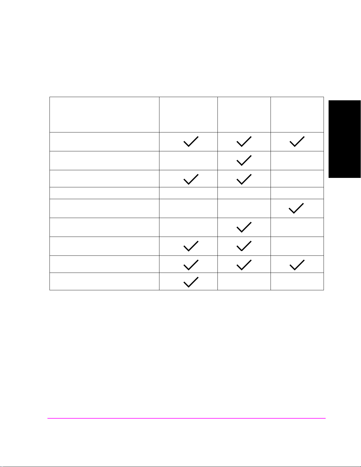
Recommended Periodic Calibration Procedures:
Chapter 1, Calibrating the Test Set
Calibration Procedures
When Test Set is being used for the first
time (allow 30-minute warmup perio d).
After extended power off cycle (allow 30minute warmup period).
After firmware is upgraded
When the "Uncal" light is flashing
Before making an Average Power measure-
ment
If the RF connections to the PCS interface
are adjusted.
If the ambient temperature changes more
than 5 degrees C since latest calibration
Ram Initialization
"Calibrating
CDMA Channel
Levels (PCB Cal)"
on page 16
"Calibrating
Channel Power
Measurements"
on page 20
"Zeroing Average
Power
Measurements"
on page 24
Calibrating the Test Set
Chapter 1
Every month
15
S:\HPe8285A\APPMOD\BOOK\CHAPTERS\amcal.fb
Page 17
Chapter 1, Calibrating the Test Set
Calibrating CDMA Channel Levels (PCB Cal)
Calibrating CDMA Channel Levels (PCB Cal)
Approximate time: 8 minutes
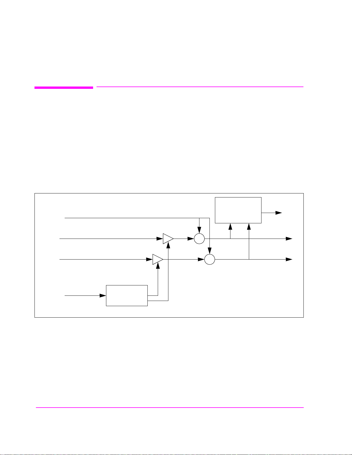
The Test Set optimizes the level accuracy of CDMA code channels and the
AWGN (Additive White Gaussian Noise) generator by measuring the analog I/Q
signals on an i nternal DSP-base d voltmete r. Level correcti on fact ors ar e genera ted
by a ROM-based program named PCB_CAL and are applied to gain control
DACs, which control the fine level adjustment in the amplitude scaling path.
Calibrated channel power provides accurate values for Eb/Nt, the ratio between
Traffic channel power and AWGN. It is critical that these levels remain accurate.
A level accuracy error of 0.8 dB could alter FER from 0.5% to 5%.
AWGN
Analog I
Analog Q
Level Correction
Factors
Procedure Overview
To DSP
Diagnostic Mux
Σ
Voltmeter
I Output
Σ
Q Output
Gain Control
DAC
For detailed step-by-step explanation see the page associated with the step.
1. "Load the PCB_CAL procedure." on page 17.
2. "Lower the Test Set’s output power if necessary." on page 26.
3. "Select the Average Power measurement." on page 27.
16
S:\HPe8285A\APPMOD\BOOK\CHAPTERS\amcal.fb
Page 18
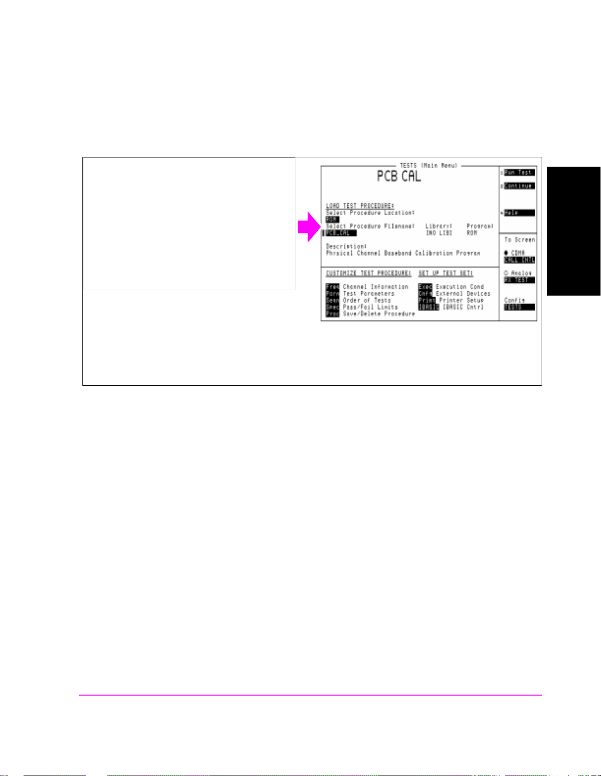
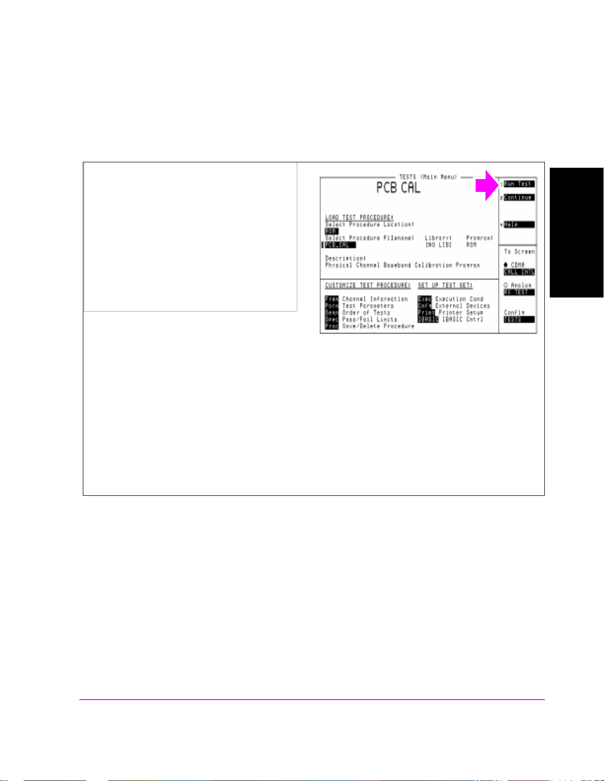
1. Load the PCB_CAL procedure.
Manual Operation:
1. Press the Tests key.
Chapter 1, Calibrating the Test Set
Calibrating CDMA Channel Levels (PCB Cal)
Calibrating the Test Set
2. Select ROM from the list of choices for the
Select Procedure Location field.
3. Select PCB_CAL from the list of choices for
the Select Procedure Filename field.
The TESTS (Main Menu) screen provides access to the Test Set’s internal IBASIC controller. You can load,
run, and customize procedures on this screen.
HP-IB Syntax
"DISP TEST" ! displays the TESTS (Main Menu) screen.
"TEST:PROC:LOC ’ROM’" ! selects ROM as the test procedure location.
"TEST:PROC:NAME ’PCB_CAL’" !selects the file named "PCB_CAL"
Chapter 1
17
S:\HPe8285A\APPMOD\BOOK\CHAPTERS\amcal.fb
Page 19

Chapter 1, Calibrating the Test Set
Calibrating CDMA Channel Levels (PCB Cal)
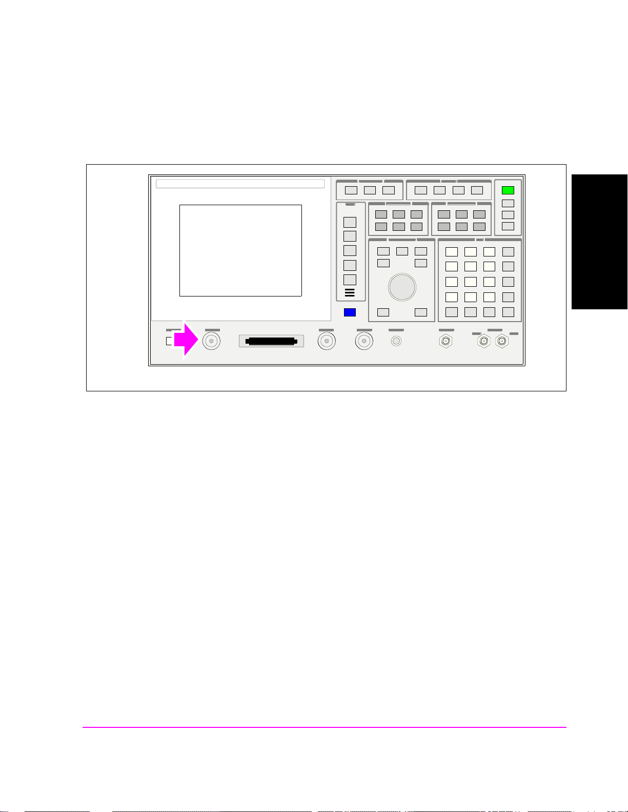
2. Remove power from the ANTENNA IN port.
Manual Operation:
1. Disconnect any cable connected to the
ANTENNA IN connector or turn off power
from any signal source connected to the
ANTENNA IN connector.
18
S:\HPe8285A\APPMOD\BOOK\CHAPTERS\amcal.fb
Page 20
3. Run the PCB_CAL Procedure.
Chapter 1, Calibrating the Test Set
Calibrating CDMA Channel Levels (PCB Cal)
Manual Operation:
1. Position the cursor next to the Ru n Test field.
2. Press the knob.
3. When the PCB_CAL procedure has completed,
cycle power.
At the beginning of the procedure, the Test Set will beep and the message "Direct latch write occurred. Cycle
power when done servicing" will appe ar. This is normal.
During this procedure the display will show cal factors for I and Q channels on the screen.When the calibration
procedure has completed, the message "Cycle instrument power to restore test set to normal operating
conditions" will be displayed at the top of the screen. Cycle power using the front panel POWER key, or send the
SYSTem:RESTart command shown below.
The PCB_CAL procedure will run for about 8 minutes unless a failure occurs. If a failure occurs, the program
will stop, bit 8 in the Calibration Status Register will be set true, and the Test Set will display "PCB CAL
UNSUCCESSFUL".
Calibrating the Test Set
Chapter 1
HP-IB Syntax
"TEST:PROC:RUN" !starts the PCB Cal routine
"STATus:OPERation:CONDition" !queries the Operation Status Register. If the PCB Cal
procedure is still running, bit 14 (IBASIC Program Running) will be set true.
"STATus:CALibration:EVENt?" !queries the Calibration Status Register. If the PCB Cal procedure failed, bit 8 will be set true.
"SYSTem:RESTart" !re-boots the Test Set (can be performed in place of cycling power)
19
S:\HPe8285A\APPMOD\BOOK\CHAPTERS\amcal.fb
Page 21

Chapter 1, Calibrating the Test Set
Calibrating Channel Power Measurements
Calibrating Channel Power Measurements
The time period for calib rati ng channe l power meas urement s depend s on the sp an
of frequencies selected. A message will be displayed to let the user know how
long the procedure will take.
The Test Set can be configured to limit calibration to specific bands, calibrate all
bands, or calibrat e the fr equency r ange corr esponding with desi gnated RF c hannel
standards (for example, Japan CDMA).
A verag e Power measurement s are zeroed as part of the Channel Power calibrat ion
process.
Procedure Overview
For detailed step-by-step explanation see the page associated with the step.
1. "Configure the Test Set to calibrate alternate frequency bands. (Optional)" on
page 21
2. "Select the Channel Power or Access Probe Power measurement." on page 22.
3. "Calibrate the Channel Power measurement." on page 23.
20
S:\HPe8285A\APPMOD\BOOK\CHAPTERS\amcal.fb
Page 22
Chapter 1, Calibrating the Test Set
Calibrating Channel Power Measurements
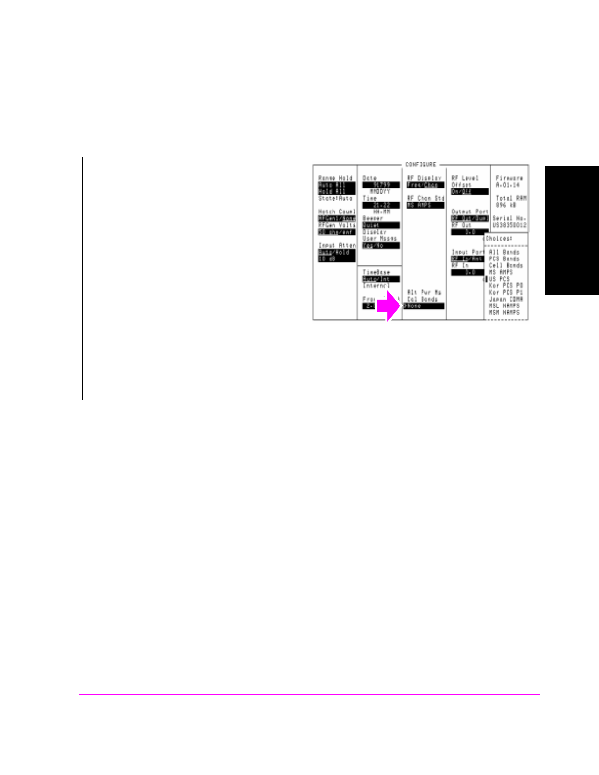
1. Configure the Test Set to calibrate alternate frequency bands. (Optional)
Manual Operation:
1. Press the Config key to display the
CONFIGURE screen.
2. Position the cursor in front of Alt Pwr Ms Cal
Bands field. Press the knob and select the
additional channel standard or complete cellular
band for channel power measurement
calibration.
Calibrating the Test Set
Chapter 1
Channel Power Calibration wil l be per formed over th e frequency bands i nclud ed i n the RF C han Std an d t he
Alt Pwr Ms Cal Bands field selections . Adding an alternate channel standard or band will increase the time
required for the Test Set to perform Channel Power Calibration.
21
S:\HPe8285A\APPMOD\BOOK\CHAPTERS\amcal.fb
Page 23

Chapter 1, Calibrating the Test Set
Calibrating Channel Power Measurements
2. Select the Channel Power or Access Probe Power measurement.
Manual Operation:
1. Position the cursor next to the field that displays
Avg Power , Acc P rb P wr, or Chan Po wer. This
field is found on the CDMA CALL
CONTROL, CDMA CELLULAR MOBILE
TRANSMITTER TEST, and CDMA
TRANSMITTER POWER RANGE TEST
screens.
2. Make sure Chan Power or Acc Prb Pwr is
selected.
HP-IB Syntax
"CDMA:TX:POW:MEAS ’Chan Power’" selects Channel Power measurements.
22
S:\HPe8285A\APPMOD\BOOK\CHAPTERS\amcal.fb
Page 24
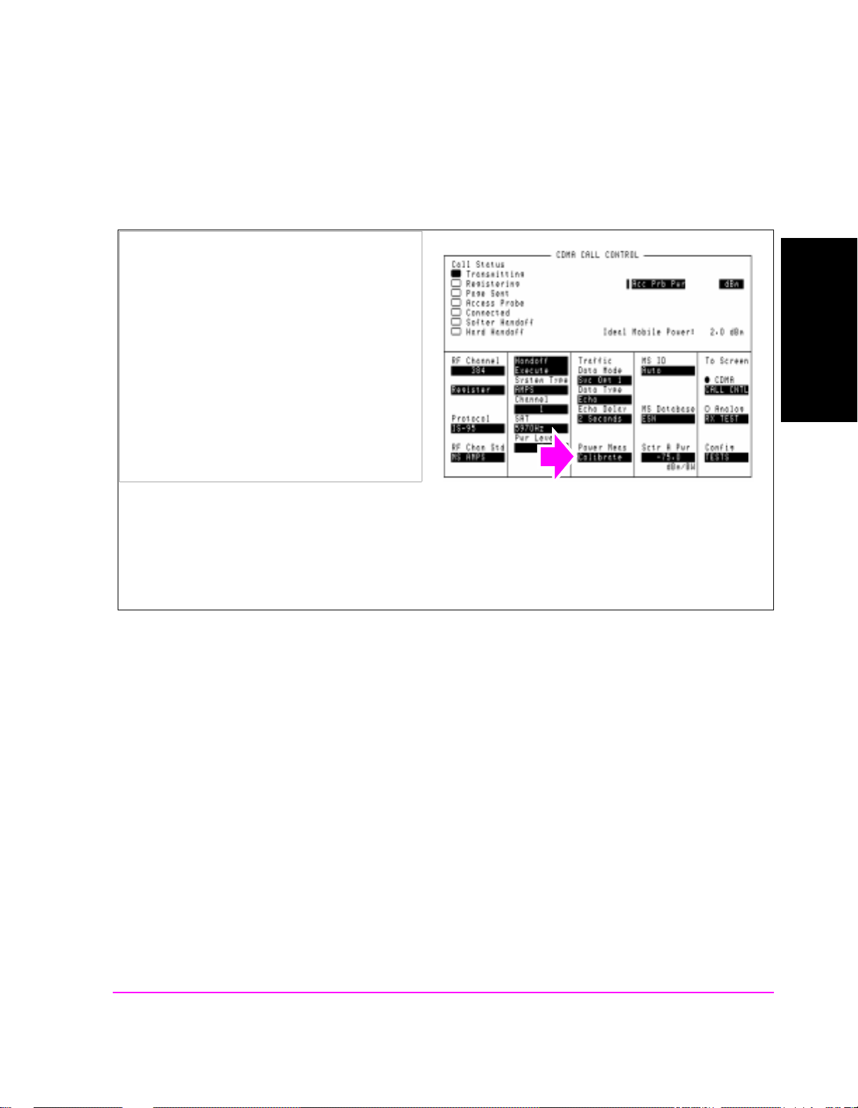
3. Calibrate the Channel Power measurement.
Chapter 1, Calibrating the Test Set
Calibrating Channel Power Measurements
Manual Operation:
1. Position the cursor next to the Power Meas
field.
2. Press the knob.
The Test Set will display "Cal takes about X
minutes. Continue?"
3. Press the Yes key.
Calibration may take a minute or longer, depending on the RF Channel Std and Alt Chn Std field settings. If
you are performing calibration using the HP-IB command below, be aware that the Test Set will accept
(handshake) HP-IB commands during the calibration routine, but none of these "buffered" HP-IB command
functions will be executed until channel power calibration is complete.
HP-IB Help
Calibrating the Test Set
Chapter 1
During the channel power calibration firmware routine, the Test Set will not respond to HP-IB queries. To
determine when this procedure is done, query the Calibrating status register. When calibration has
completed, the Test Set will return a value with bit 0 and bit 1 set true.
If your controlling application has an I/O timeout enabled make sure that sufficient time is given for the
Test Set to complete calibration and provide a query response in its output queue. Or, disable the timeout
during channel power calibration.
HP-IB Syntax
"MEAS:CDM:CHAN:CAL" !calibrates Channel Power measurements.
"STAT:OPER:CAL:EVENt?" !queries the Calibrating Status Event Register.
Bit 1 is the channel power calibration bit.
23
S:\HPe8285A\APPMOD\BOOK\CHAPTERS\amcal.fb
Page 25

Chapter 1, Calibrating the Test Set
Zeroing Average Power Measurements
Zeroing Average Power Measurement s
Approximate length of time: 2 seconds
Average Power measurements should be zeroed before each measurement or
series of m easurements.
NOTE: A misleading Average Power measurement may appear when low (or no) signal power
is applied to the RF Input! When the RF generator’s output port selection is RF IN/
OUT, some of the signal energy from the Test Set’s generator is detected by the Test Set’s
broadband average power meter. This condition does not affect typical CDMA
measurements for two reasons: 1) During Average Power m easurements CDMA gener ator
levels are too low to introduce significant energy to the power detector. 2) When the
generator level is high enough to introdu ce significant energy to the power detector, the
mobile station’s signal power should be within the range of Channel Power measurements.
Channel power measurements are frequency-selective, and d o not detect significant energy
from the Test Set’s generator, which is tuned 45 MHz away from the analyzer.
Procedure Overview
For detailed step-by-step explanation see the page associated with the step.
1. "Remove power from the RF IN/OUT connector." on page 25.
2. "Lower the Test Set’s output power if necessary." on page 26.
3. "Select the Average Power measurement." on page 27.
4. "Zero the Average Power measurement." on page 28.
24
S:\HPe8285A\APPMOD\BOOK\CHAPTERS\amcal.fb
Page 26
1. Remove power from the RF IN/OUT connector.
Chapter 1, Calibrating the Test Set
Zeroing Average Power Measurements
Calibrating the Test Set
Chapter 1
25
S:\HPe8285A\APPMOD\BOOK\CHAPTERS\amcal.fb
Page 27
Chapter 1, Calibrating the Test Set
Zeroing Average Power Measurements
2. Lower the Test Set’s output power if necessary.
Manual Operation:
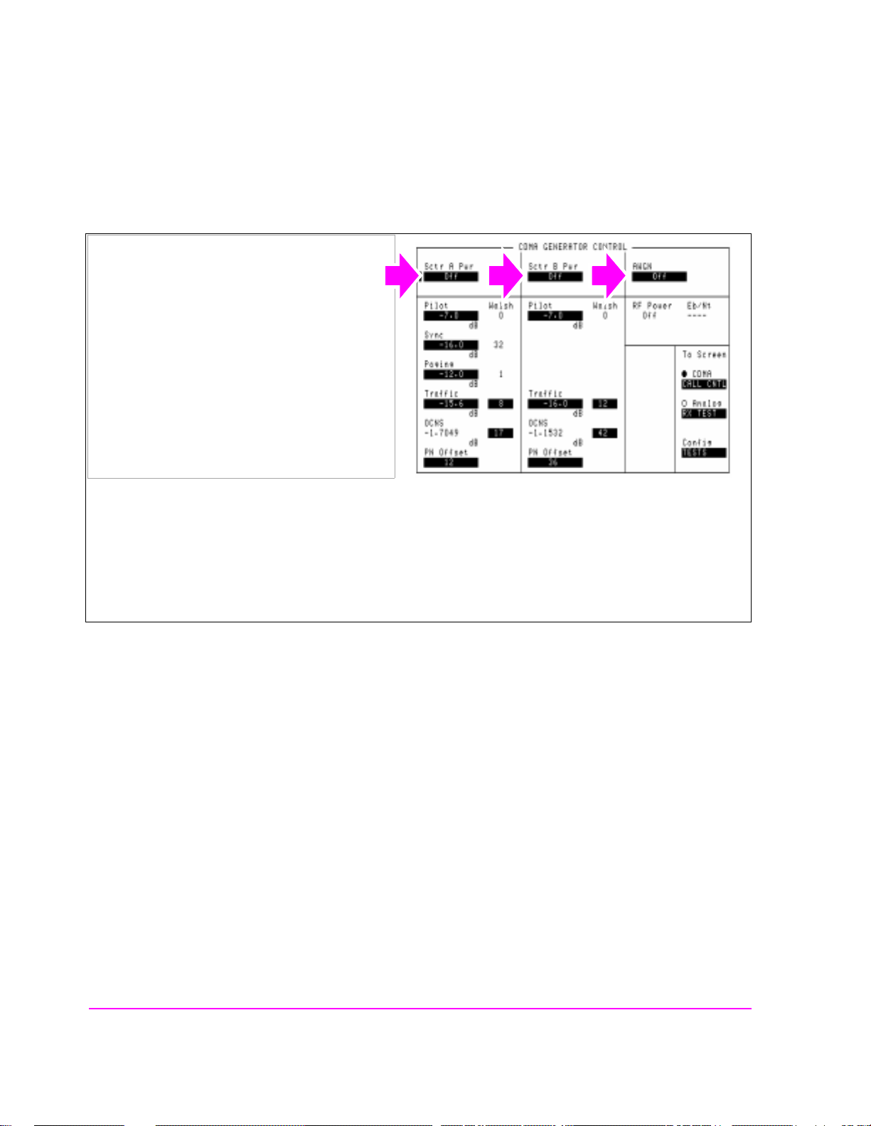
1. Press the Preset key, which will set RF Power
to a level that will not degrade Average Power
zeroing, or turn off all sources as follows:
1a. Press the Gen Control key to dis play the
CDMA
1b. Turn off Sector A Power, Sector B Power,
and AWGN (by pressing the ON/OFF key on
the Test Set’s front panel).
GENERATOR CONTROL screen.
Turning off power from the CDMA generators will prevent power from cross-coupling internally to the
RF IN/OUT path during Average Power measurement zeroing.
Presetting the test Set (*RST HP-IB command) will turn off Sector B and AWGN, and will lower Sector A
Power to a level that will not affect zeroing the Average Power measurement, making it unnecessary to turn
Sector A Power off.
HP-IB Syntax
"CDMA:CELL:ASEC:STAT OFF" !turns off Sector A Power
"CDMA:CELL:BSEC:STAT OFF" !turns off Sector B Power
"CDMA:AWGN:STAT OFF" !turns off AWGN
26
S:\HPe8285A\APPMOD\BOOK\CHAPTERS\amcal.fb
Page 28
3. Select the Average Power measurement.
Chapter 1, Calibrating the Test Set
Zeroing Average Power Measurements
Manual Operation:
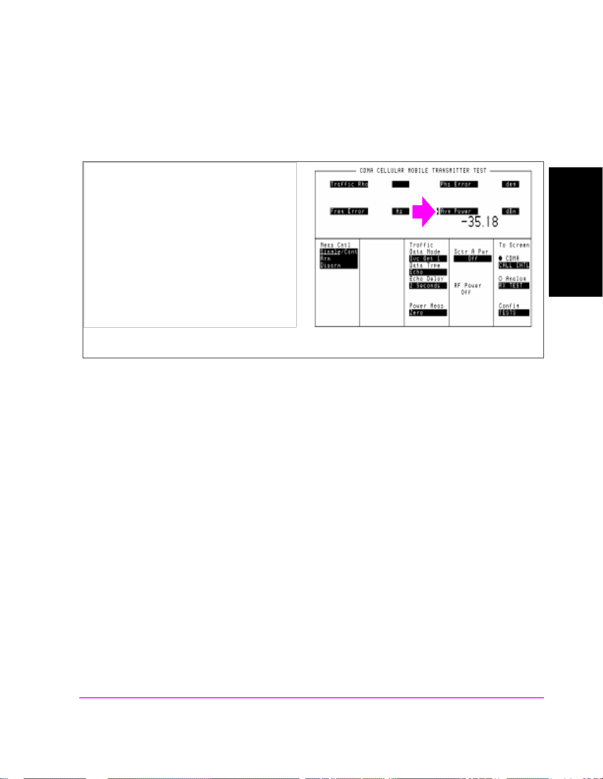
1. Press the CDMA SCREENS - Tx test key to
display the CDMA CELLULAR MOBILE
TRANSMITTER TEST screen.
2. Position the cursor next to the field as shown.
3. Press the knob to select the Choices menu.
4. Select Avg Power from the list.
HP-IB Syntax
"CDMA:TX:POW:MEAS ’Avg Power’" selects Average Power measurements.
Calibrating the Test Set
Chapter 1
27
S:\HPe8285A\APPMOD\BOOK\CHAPTERS\amcal.fb
Page 29
Chapter 1, Calibrating the Test Set
Zeroing Average Power Measurements
4. Zero the Average Power measurement.
Manual Operation:
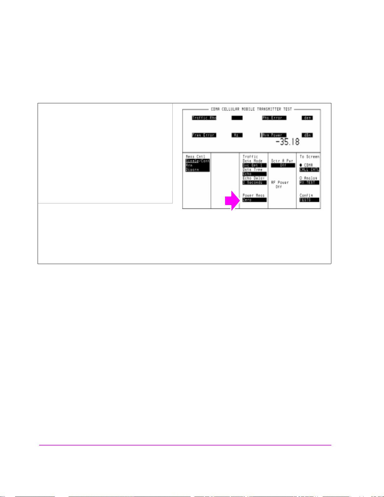
1. Press the CDMA SCREENS - Tx test key to
display the CDMA CELLULAR MOBILE
TRANSMITTER TEST screen.
2. Position the cursor next to the Zero field.
3. Press the knob.
Zeroing Average Power takes approximately
two seconds.
If RF power was not lowered as shown in step 2, the Test Set will display "Zero degraded. Reduce generator
level for best results" .
HP-IB Syntax
"MEAS:CDM:AVGP:ZERO" ! zeroes the average power meter.
28
S:\HPe8285A\APPMOD\BOOK\CHAPTERS\amcal.fb
Page 30

Chapter 1, Calibrating the Test Set
Correcting for RF Path Loss
Correcting for RF Path Loss
Approximate time: N/A (this pro cedure is simpl y a field entry).
The Test Set provides fields to enter independent path loss values for the forward
and reverse channels to compensate for the differences in frequency response.
The settings you make in the following procedure must be re-entered after a
power-cycle, instrument preset, or HP-IB reset ("*RST).
It is highly recommended that RF path loss is corrected for in the following
manner.
NOTE: The Test Set’s attenuator auto-ranging algorithm, used for adjusting gain in the RF analyzer
path, estimates the expected power level from the phone using the open loop power cont rol
formula. External path loss, entered in the procedure below, is used by the auto-ranging
algorithm to ensure the analyzer is not overdriven or underdriven.
Procedure Overview
For detailed step-by-step explanation see the page associated with the step.
1. "Enter the forward channel path loss from the Test Set to the MSUT." on page 30.
2. "Enter the reverse channel path loss from the Test Set to the MSUT." on page 31.
3. "Turn on RF Level Offset." on page 32.
Calibrating the Test Set
Chapter 1
29
S:\HPe8285A\APPMOD\BOOK\CHAPTERS\amcal.fb
Page 31

Chapter 1, Calibrating the Test Set
Correcting for RF Path Loss
1. Enter the forward channel path loss from the Test Set to the MSUT.
If you do not know the path loss for your connecting hardware, see "Determining
RF Path Loss" on page 33
Manual Operation:
1. Press the Config key to display the
CONFIGURE screen.
2. Position the cursor in front of the selected
Output Port field (Duplex Out or RF Out) and
enter a value for RF path loss.
Example: If the measured loss is 2 dB, and RF Out is selected in the Output Port field, enter -2 dB in the RF
Out field. When the RF Level Offset is turned on, the displayed
outputs will be decreased by 2 dB. No actual level changes occur as a result of turning on RF Level Offset.
Sector A, Sector B, AWGN, and RF Power
30
S:\HPe8285A\APPMOD\BOOK\CHAPTERS\amcal.fb
Page 32

Chapter 1, Calibrating the Test Set
Correcting for RF Path Loss
2. Enter the reverse channel path loss from the Test Set to the MSUT.
If you do not know the path loss for your connecting hardware, see "Determining
RF Path Loss" on page 33
Calibrating the Test Set
Manual Operation:
1. Position the cursor in front of the selected Input
Port field (RF In or Antenna In) and enter a
value for RF path loss.
Example: If the measured loss is 2 dB, an d RF In is
selected in the Input Port field, enter -2 dB in the RF In field. When the RF Level Offset is turned on, the
displayed Average, Access Probe, or Channel Power measurement will be increased by 2 dB.
Chapter 1
31
S:\HPe8285A\APPMOD\BOOK\CHAPTERS\amcal.fb
Page 33
Chapter 1, Calibrating the Test Set
Correcting for RF Path Loss
3. Turn on RF Level Offset.
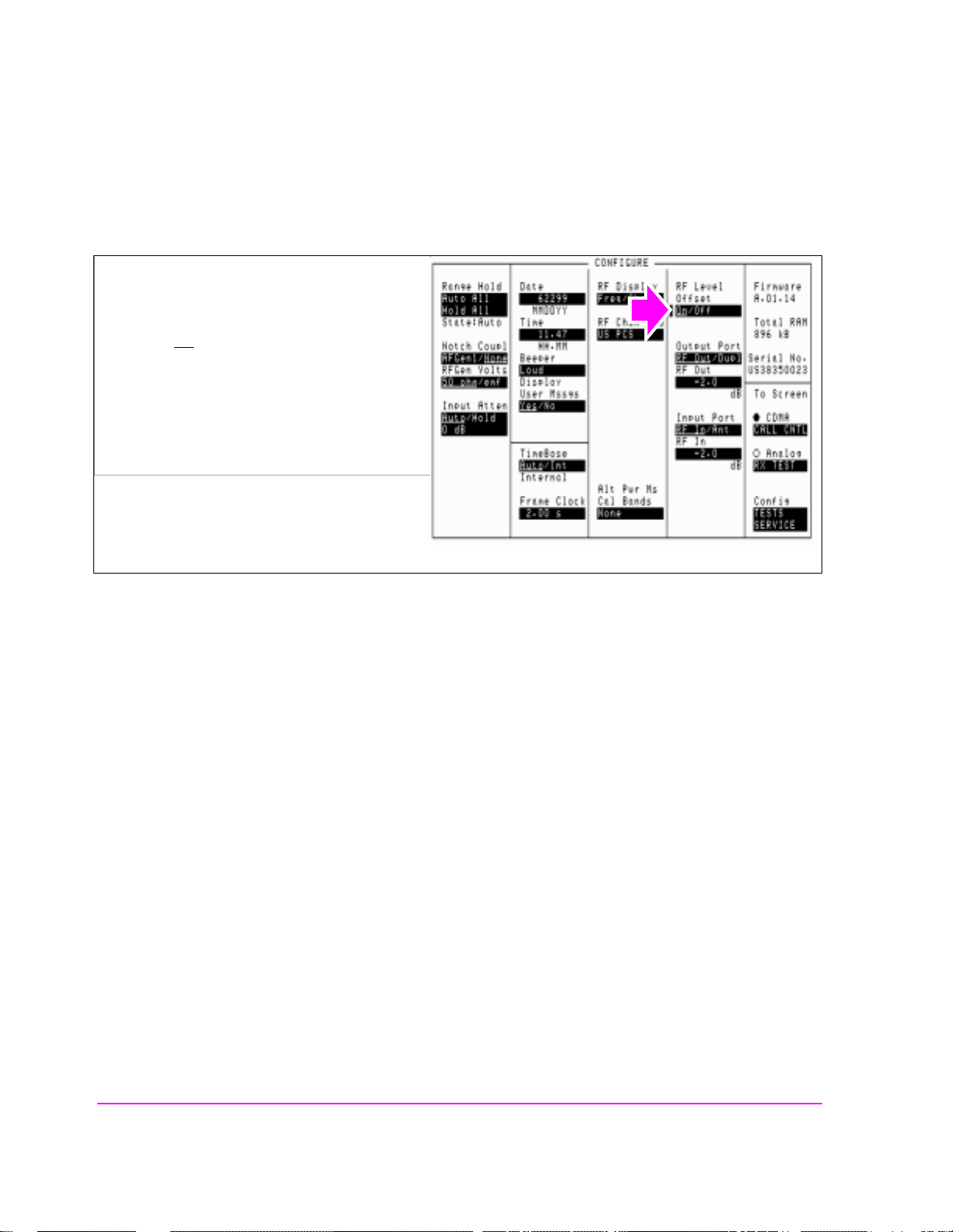
Manual Operation:
1. Position the cursor at the RF Level Offset field.
2. Select "On
" to correct for RF path loss.
32
S:\HPe8285A\APPMOD\BOOK\CHAPTERS\amcal.fb
Page 34

Chapter 1, Calibrating the Test Set
Determining RF Path Loss
Determining RF Path Loss
The following procedure describes how to use the Test Set’s signal generator and
analyzer to determine path loss.
NOTE: The Test Set’s attenuator auto-ranging algorithm, used for adjusting gain in the RF analyzer
path, estimates the expected power level from the phone using the open loop power cont rol
formula. External path loss, entered in the procedure below, is applied to the auto-ranging
algorithm to ensure the analyzer is not overdriven or underdriven.
Procedure Overview
For detailed step-by-step explanation see the page associated with the step.
1. "Procedure Prerequisites" on page 34.
2. "Configure the Test Set to be tuned to a frequency." on page 35.
3. "Configure the Test Set for RF loopback." on page 36.
4. "Connect a reference cable." on page 37.
5. "Enter a forward or reverse channel frequency value." on page 38.
6. "Set a 0 dBm reference for the path loss measurement." on page 39.
7. "Enter the CDMA forward or reverse channel path loss." on page 42.
Calibrating the Test Set
Chapter 1
33
S:\HPe8285A\APPMOD\BOOK\CHAPTERS\amcal.fb
Page 35

Chapter 1, Calibrating the Test Set
Determining RF Path Loss
1. Procedure Prerequisites
User-supplied reference cabling, including:
• (2) 3 dB Attenuators
• (2) Cable Adapters
• (1) Low-loss cable
The reference cabling will connect the Test Set’s RF output to RF input for the
purpose of making a reference meas ure me nt . The addition of the 3 dB att enuators
minimizes the effects of VSWR during the path loss measurement.
Zero the Tx Power measurement
1. Remove power from the RF IN/OUT and ANTENNA IN connectors.
2. Press the ANALOG SCREENS TX test key to display the TX TEST screen.
3. Position the cursor in front of the TX Pwr Zero field.
4. Press the knob.
34
S:\HPe8285A\APPMOD\BOOK\CHAPTERS\amcal.fb
Page 36
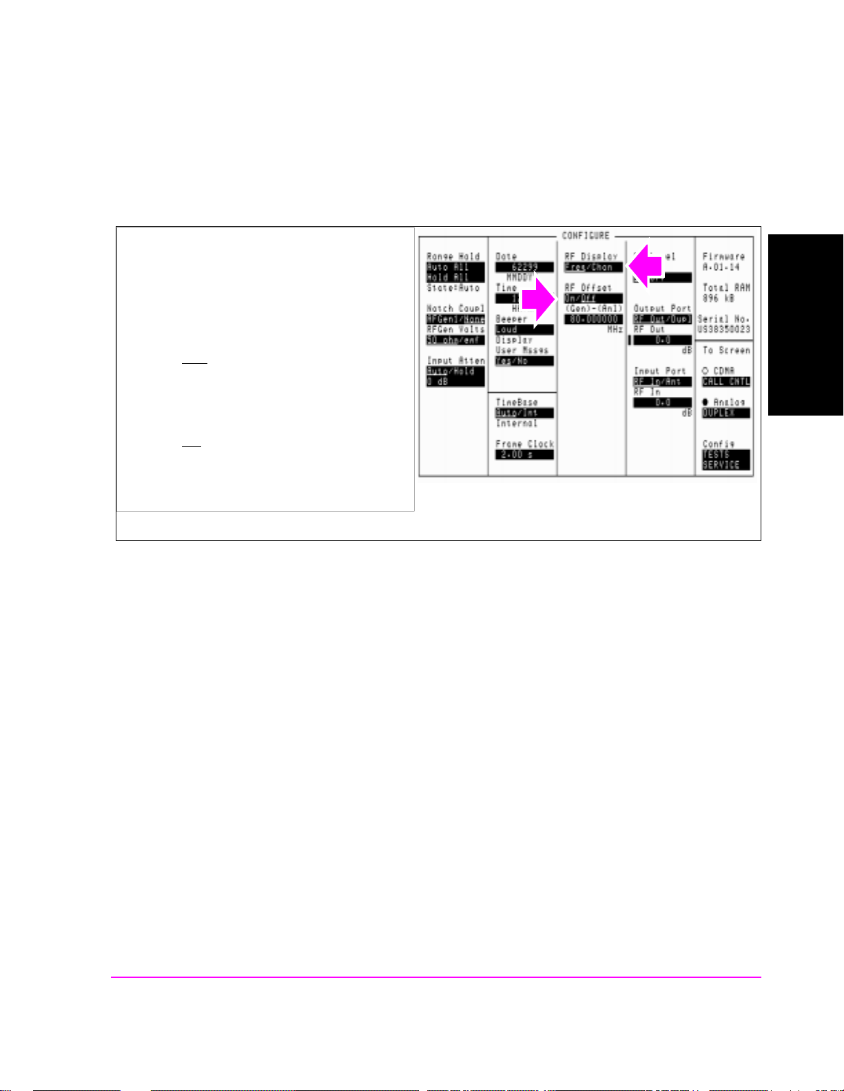
2. Configure the Test Set to be tuned to a frequency.
Chapter 1, Calibrating the Test Set
Determining RF Path Loss
Manual Operation:
1. Press the UTILITIES Config key to display the
CONFIGURE screen.
2. Position the cursor at the RF Display field.
3. Select Freq
underlined sele ction.
4. Position the cursor at the RF Offset field.
5. Select Off
underlined sele ction.
by pressing the knob to toggle the
by pressing the knob to toggle the
Calibrating the Test Set
Chapter 1
35
S:\HPe8285A\APPMOD\BOOK\CHAPTERS\amcal.fb
Page 37
Chapter 1, Calibrating the Test Set
Determining RF Path Loss
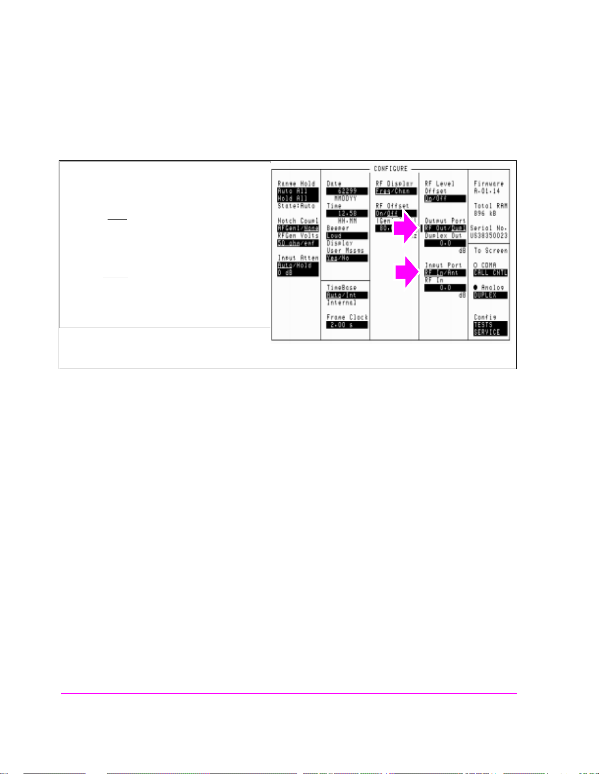
3. Configure the Test Set for RF loopback.
Manual Operation:
1. Position the cursor at the Output Port field.
2. Select Dupl
underlined sele ction.
3. Position the cursor at the Input Port field.
4. Select RF In
by pressing the knob to t oggle the
.
36
S:\HPe8285A\APPMOD\BOOK\CHAPTERS\amcal.fb
Page 38
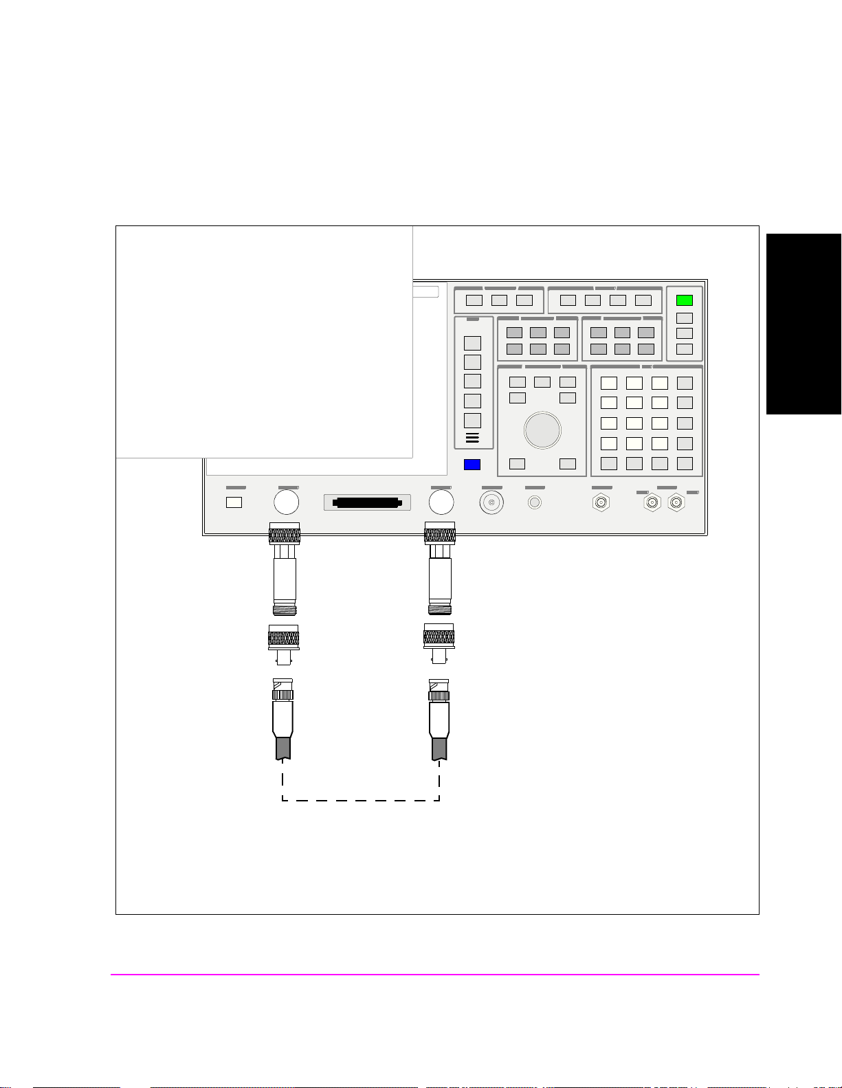
4. Connect a reference cable.
Chapter 1, Calibrating the Test Set
Determining RF Path Loss
Manual Operation:
1. Connect cable as shown.
Calibrating the Test Set
Chapter 1
3 dB attenuators
Cable adapters
Reference cable
37
S:\HPe8285A\APPMOD\BOOK\CHAPTERS\amcal.fb
Page 39

Chapter 1, Calibrating the Test Set
Determining RF Path Loss
5. Enter a forward or reverse channel frequency value.
Manual Operation:
1. Press the ANALOG SCREENS - Duplex key
to display the DUPLEX TEST screen.
2. Position the cursor at the Tune Freq field.
3. Set the value to the CDMA mobile station’s
forward or reverse channel frequency.
4. Position the cursor at the RF Gen Freq field.
5. Set the value to the CDMA mobile station’s
forward or reverse channel frequency.
The Tune Freq and RF Gen Freq fields should
now be set to the same frequency.
38
S:\HPe8285A\APPMOD\BOOK\CHAPTERS\amcal.fb
Page 40

6. Set a 0 dBm reference for the path loss measurement.
Manual Operation:
1. Position the cursor at the Amplitude field.
2. Set the value to 0 dBm with the DATA keys.
3. Position the cursor at the Tx Power units-ofmeasure field.
4. Turn on the Tx Power measurement.
5. With the cursor positioned at the units-ofmeasure field for the TX power measurement,
press the dBm key.
Chapter 1, Calibrating the Test Set
Determining RF Path Loss
Calibrating the Test Set
Chapter 1
6. Press and release the SHIFT key, followed by
the INCR ÷
10 key (Ref set).
8. Press the knob. The "Ref" annunciator
should appear, indicating that a reference
value has been set. The TX Power
measurement should be cl ose to 0.01 dBm.
39
S:\HPe8285A\APPMOD\BOOK\CHAPTERS\amcal.fb
Page 41

Chapter 1, Calibrating the Test Set
Determining RF Path Loss
7. Connect the cable and hardware being measured for path loss.
Reference cable
3 dB attenuators
Cable adapters
RF path being measured
Mobile Station Test Fixture
Low-loss reference cable
40
S:\HPe8285A\APPMOD\BOOK\CHAPTERS\amcal.fb
Page 42

8. Obtain the value of the RF path loss.
Manual Operation:
1. Look at the display for the value.
Chapter 1, Calibrating the Test Set
Determining RF Path Loss
Calibrating the Test Set
Chapter 1
41
S:\HPe8285A\APPMOD\BOOK\CHAPTERS\amcal.fb
Page 43

Chapter 1, Calibrating the Test Set
Determining RF Path Loss
9. Enter the CDMA forward or reverse channel path loss.
The TX Power measurement obtained from the previous step is the measured RF
path loss for the forward or reverse channel, and should be entered in the Test
Set’s RF Out or Duplex Out field (if the measurement was on a forward channel
frequency) or the RF In or Antenna In field (if the measurement was on a reverse
channel frequency).
Manual Operation:
1. Press the UTILITIES Config key to display the
CONFIGURE screen.
2. Select the Output Port and Input Port settings
you will use during mobile station tes ting.
See "Correcting for RF Path Loss" on page 29.
3. If the frequency setting was for the forward
CDMA channel, position the cursor at the
Output Port field and enter the value obtained
from the previous step. you will use during
mobile station testing.
4. If the frequency setting was for the reverse
CDMA channel, position the cursor at the Input
Port field and enter the value obtained from the
previous step.
5. Turn the RF Level Offset field On.
42
S:\HPe8285A\APPMOD\BOOK\CHAPTERS\amcal.fb
Page 44

10. Return the Test Set to display RF channels.
Chapter 1, Calibrating the Test Set
Determining RF Path Loss
Manual Operation:
1. Position the cursor at the RF Display field.
2. Select Chan
underlined selection.
by pressing the knob to toggle the
Calibrating the Test Set
Chapter 1
43
S:\HPe8285A\APPMOD\BOOK\CHAPTERS\amcal.fb
Page 45

Chapter 1, Calibrating the Test Set
Determining RF Path Loss
44
S:\HPe8285A\APPMOD\BOOK\CHAPTERS\amcal.fb
Page 46

2
Setting Up a Call
Chapter 2
Setting Up a Call
45
S:\HPe8285A\APPMOD\BOOK\CHAPT ERS\amcall.fb
Page 47

Chapter 2, Setting Up a Call
Steps for Setting Up a Call
Steps for Setting Up a Call
Procedure Overview
For detailed step-by-step explanation see the page associated with the step.
1. "Connect the MSUT to the Test Set." on page 47.
2. "Turn on power to the MSUT and wait for the MSUT to find digital service." on
page 48.
3. "Select the desired Service Option." on page 49.
4. "Register the MSUT (Optional)." on page 50.
5. "Make a call." on page 52.
"MSUT-Terminated Call" on page 52
"MSUT-Originated Call ." on page 53
46
S:\HPe8285A\APPMOD\BOOK\CHAPTERS\amcall.fb
Page 48

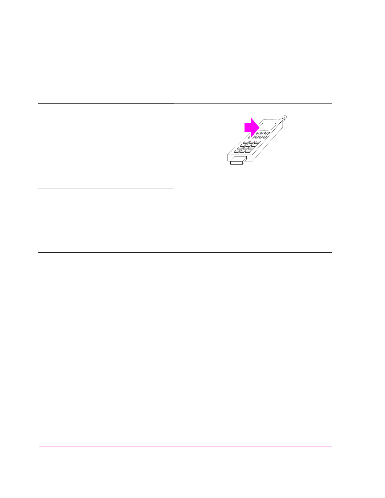
1. Connect the MSUT to the Test Set.
Manual Operation:
1. Connect the MSUT to the Test Set’s
RF IN/OUT connector.
Chapter 2, Setting Up a Call
Steps for Setting Up a Call
Make sure all connections to the MSUT, including dc power, are made.
Some MSUT’s do not have an RF connection. The MSUT manufacturer will usually make a fixture, such as a
car adapter, that will provide an RF cable connection to the Test Set. The MSUT is then snapped into the fixture
and an RF connection is made through an electromagnetic coupler near the MSUT antenna. When setting up a
call with these type of MSUT’s, the MSUT may need to be isolated from interfering signals.
Setting Up a Call
Chapter 2
47
S:\HPe8285A\APPMOD\BOOK\CHAPT ERS\amcall.fb
Page 49
Chapter 2, Setting Up a Call
Steps for Setting Up a Call
2. Turn on power to the MSUT and wait for the MSUT to find digital service.
Manual Operation:
Wait until the MSUT has found digital service (this
should take no longer than about 30 seconds).
If the MSUT does not find service, refer to
"Checklist 1. MSUT did not find service" on
page 55.
Most MSUT’s have a NO SERVICE annunciator that will go out when the mobile station has found service.
Other MSUT’s use an LED that indicates when service has been found. If the MSUT is programmed to prefer
analog service, and a strong signal from an analog base station is present, the MSUT may not find digital
service. If this condition exists, re-program the phone or isolate it from the competing analog signal.
Caution: Do not exceed 6 W continuous power into the Test Set’s RF IN/OUT connector with any transmitter.
48
S:\HPe8285A\APPMOD\BOOK\CHAPTERS\amcall.fb
Page 50

3. Select the desired Service Option.
Manual Operation:
1. Position the cursor at the Traffic Data Mode
field.
2. Press the knob to select the field.
3. Select a Service Option.
Chapter 2, Setting Up a Call
Steps for Setting Up a Call
Service Option 1 and 9 select voice loopb ack (n ormal traffic) mode. When a Service Opt ion 1 or 9 call is
connected, the Test Set will echo voice information back to the MSUT with a settable delay.
Service Option 2 and 32768 select data loopback mode specified by IS-98 for MSUT receiver testing.
HP-IB Syntax:
"DISP CCNT;CDMA:CALL:TRAF:DATA:MODE ’SVC OPT 2’"
!selects service option 2 (data loopback mode)
Setting Up a Call
Chapter 2
49
S:\HPe8285A\APPMOD\BOOK\CHAPT ERS\amcall.fb
Page 51

Chapter 2, Setting Up a Call
Steps for Setting Up a Call
4. Register the MSUT (Optional).
If you are going to make a call from the MSUT, or if you allow the MSUT to
perform a power- up regi stra ti on, you can s kip thi s st ep and co ntinue with
Originated Call ." on page 53
Manual Operation:
1. Optional: Select *Clr All* in the MS Database
list of choices to remove any data from
previous registrations.
2. Press the Register key. The Registering
annunciator will light.
"MSUT-
.
3. Watch for the Registering annunciator to go
out. If the registration attempt times out, refer
to "Checklist 2. Registration failed" on page
57.
Registration provides the Test Set with the MSUT’s
identification, enabling the Test Set to correc tly addre ss pages to the MSU T. (An alternative method for
providing the Test Set with the MSUT’s identification is to enter Phone Number, MIN, or IMSI directly into the
MS ID field on t he CDMA Cal l Cont r ol sc r e en. Th is al ternat ive m ethod could r esu lt in s ignif icant time s avin gs in
a production test environment but the numbers you enter must precisely matc h the internal NAM (Numeric
Assignment Module) settings in the MSUT and the MSUT must be non-slotted).
When the Register field is selected, values entered in the CDMA Cell Site Configuration screen’s Rgstr SID and
Rgstr NID fields are sent to the MSUT in a message called the System Parameters message. This SID/NID pair
causes the MSUT to p erfo rm a “zon e- ba sed” registr at ion. The Rgs tr SI D an d Rgst r N ID fi elds are set by def au lt
to 12. These v alues do not ne ed to be chan ged unles s the MSUT i s programmed to n ot recogniz e the m as v alid , or
the MSUT recognizes them as its home SID/NID. If either of these conditions exist, change Rgstr SID and Rgstr
NID to arbitrary values that are both valid for the MSUT and do not match the MSUT’s home SID/NID.
50
S:\HPe8285A\APPMOD\BOOK\CHAPTERS\amcall.fb
Page 52

Chapter 2, Setting Up a Call
Steps for Setting Up a Call
HP-IB Help: The Call Status Registering annunciator is assigned to bit 11 in the CDMA Status
Register Group. The following program example polls the CDMA Status Event
Register until bit 11, Mobile Station Registered, goes true.
HP-IB Syntax:
DISP CCNT;CDMA:MOB:REG !causes the mobile station to register.
HP BASIC Example
1 RE-SAVE "C:\HPBASIC\REG"
10 OUTPUT 714;"CDMA:MOB:DAT ’*Clr All*’" !Clears MS Database values
20 OUTPUT 714;"CDMA:MOB:REG"!Begins the zone-based registration process
30 T=TIMEDATE
40 REPEAT
50 OUTPUT 714;"stat:cdma:even?" !Queries CDMA Status Event Register
60 ENTER 714;Reg
70 IF TIMEDATE-T>=25 THEN
80 PRINT "ERROR"
90 STOP
100 ELSE
110 WAIT .1 !Prevents HP-IB commands from dominating Test Set processes
120 END IF
130 UNTIL BIT(Reg,11)
140 END
Setting Up a Call
Chapter 2
51
S:\HPe8285A\APPMOD\BOOK\CHAPT ERS\amcall.fb
Page 53
Chapter 2, Setting Up a Call
Steps for Setting Up a Call
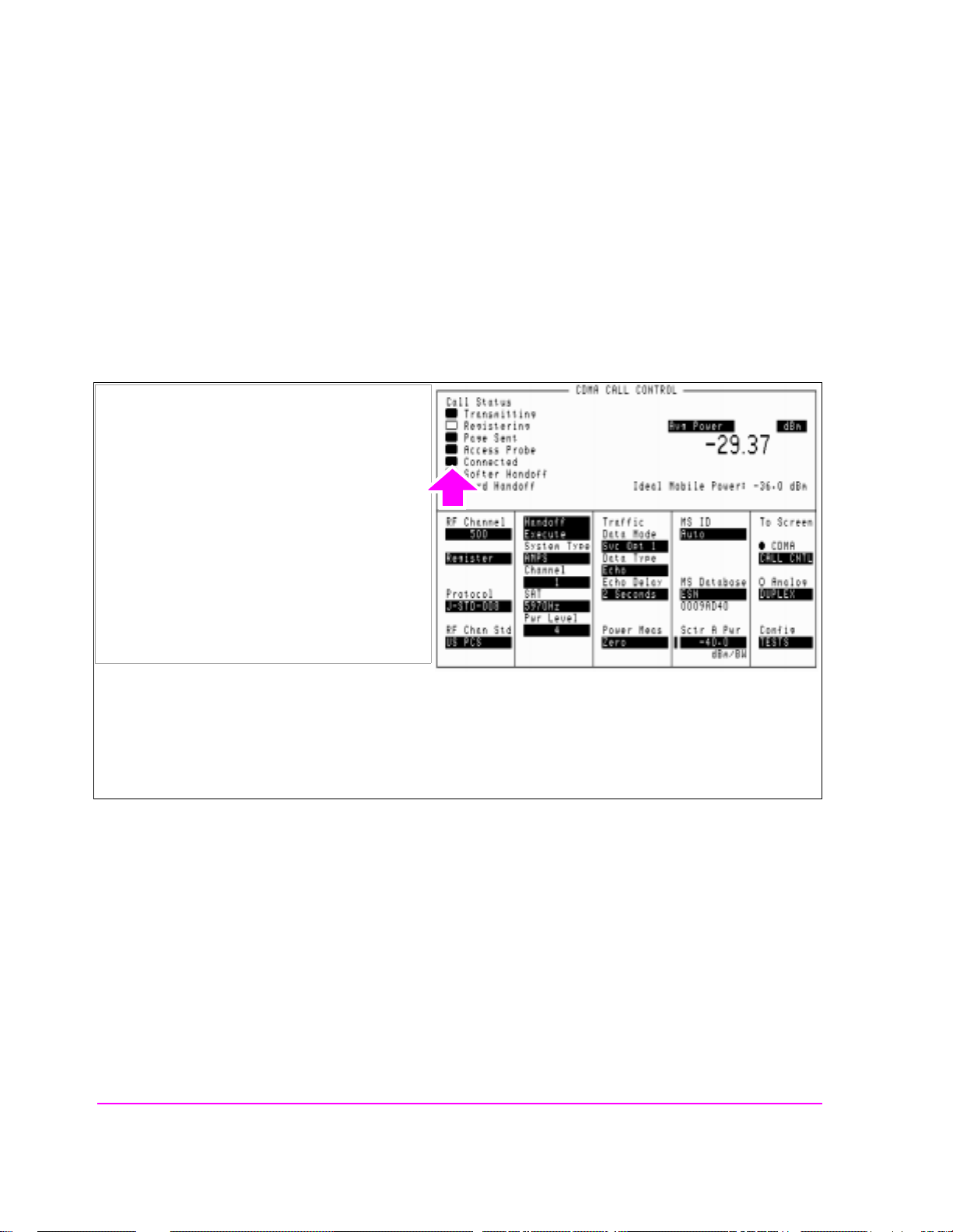
5. Make a call.
The Test Set supports both the following MSUT-terminated (originated from the
T est Set), or MSUT-originated calls. The foll owing section descr ibes both types of
calls.
MSUT-Terminated Call
Manual Operation:
1. Press the Test Set’s Call/Page key. (The phone
will not ring if you have selected a service
option 2 or 9 call).
2. If the service option 1 or 32768 is selected,
press the SEND key on the MSUT’s keypad to
connect the call.
3. Verify that the Connected annunciator is lit.
Optional: Speak into the phone to test voice
quality if service option 1 or 32768 is selected.
After the CALL key is pressed on the T est Set, the
Page Sent annunciator will light to indicate that a paging message was sent to the MSUT. The Access Probe
annunciator will then light to indicate that the mobile station transmitted an access probe sequence in an
attempt to gain system access. The MSUT should ring if the Traffic Data Mode is set to service option 1 or
HP-IB Help: The following CDMA Status Register Group bits monitor the call processing
states:
• Page Sent (BCD 2)
• Access Probe (BCD 1)
• Alerting (BCD 16)
• Connected (BCD 8)
Condition registers are implemented for these bits, allowing HP-IB operation to mirro r
the way they work on the display.
HP-IB Syntax:
"CDMA:CALL:MAKE" !makes a call from the Test Set (mobile terminated).
52
S:\HPe8285A\APPMOD\BOOK\CHAPTERS\amcall.fb
Page 54
Chapter 2, Setting Up a Call
Steps for Setting Up a Call
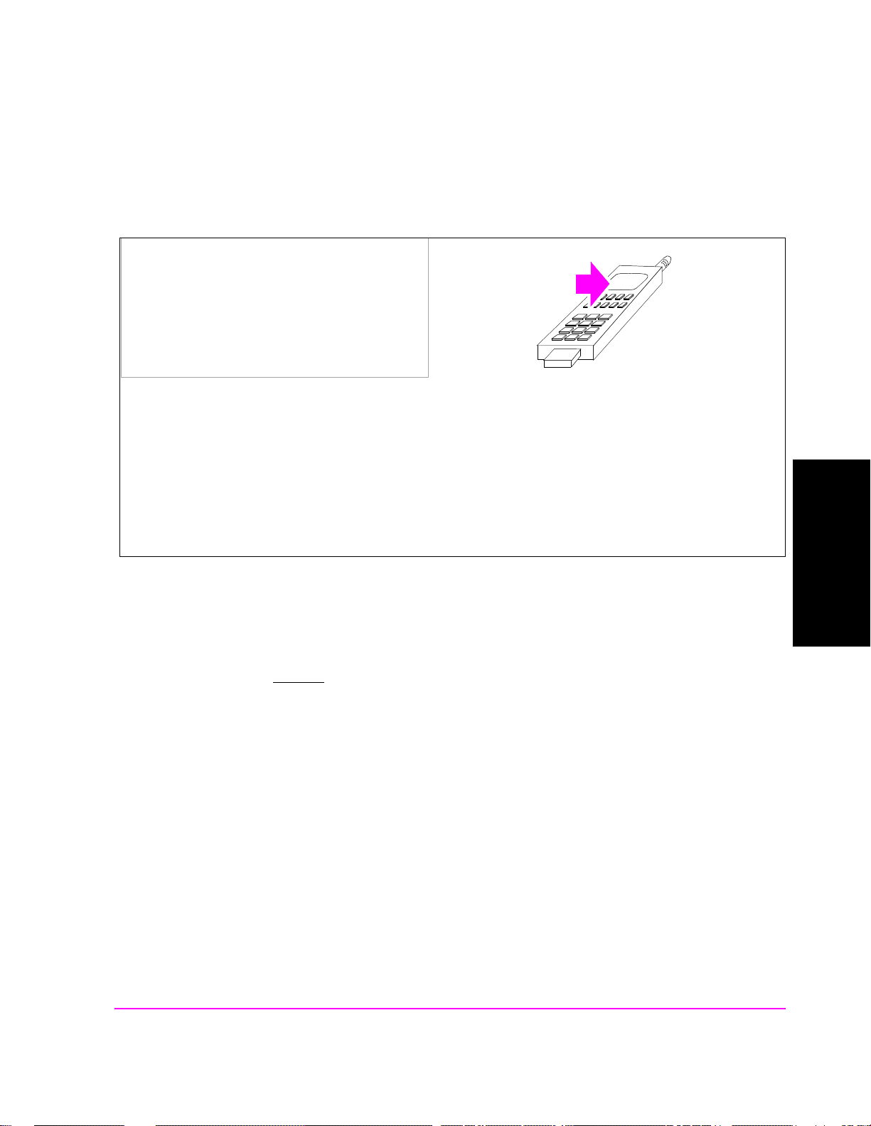
MSUT-Originated Call .
Manual Operation:
Enter any phone number on the MSUT’s keypad
and press the SEND key.
After Send is pressed on the MSUT, the Access Probe annunciator on the Test Set will light to indicate that the
mobile station sent an access probe sequence in an attempt to gain system access.
The Test Set’s Connected annunciator will light indicatin g that the MSUT is in the "Mobile Station C on trol on
the Traffic Channel State."
If the Test Set’s Answer Mode field is set to Manual, you must press the Test Set’s ANS key to manually answer
the phone.
HP-IB Help: Refer to "MSUT-Term inated Call" on page 52"
HP-IB Syntax:
"CDMA:CALL:ANSW" !answers a call from the MSUT.
(This command is only necessary when the T est Set’s Answer Mode field is
Manual).
HP-IB Example: The following HP BASIC example uses service requests to detect when the
following ca ll-processing events occur:
• Page Sent
• Alerting (not included as a front-panel display annunciator
• Connected
See "CDMA Status Register Group" in the Status Reporting chapter of the
HP E8285A User’s Guide.
Setting Up a Call
Chapter 2
53
S:\HPe8285A\APPMOD\BOOK\CHAPT ERS\amcall.fb
Page 55

Chapter 2, Setting Up a Call
Steps for Setting Up a Call
10 Status_byte = SPOLL(714) !clears the Status Byte Register
20 OUTPUT 714;"*CLS" !clears all event registers
30 CALL Cdma_register_enable 31 !calls subprogram to enable selected bits in
31 !the CDMA Status Register Group
40 CALL Operation_register_enable !calls subprogram to enable selected bit in
41 !the Operation Status Register Group.
50 ALL Status_register_enable !calls subprogram to enable bit in
51 !the Status Byte Register.
60 ON INTR 7,15 CALL Interrupt !specifies a program branch to Interrupt
61 !subprogram when an interrupt occurs.
70 ENABLE INTR 7;3 !enables the SRQ interrupt (Decimal 2 enables bit 1 of the
80 PRINT "WHEN MOBILE STATION IS REGISTERED, PRESS CONTINUE"
90 PAUSE
100 OUTPUT 714;"DISP CCNT;CDMA:CALL:MAKE"
110 LOOP
120 DISP "WAITING FOR A SERVICE REQUEST INTERRUPT"
130 END LOOP
140 END !End of program
150 SUB Cdma_register_enable
160 OUTPUT 714;"STATUS:CDMA:PTR 26;NTR 0"
161 !enables the CDMA Status Register Group positive
162 !transition register for the following bits:
163 !Page Sent (1), Alerting (4), and Connected (3)
170 OUTPUT 714;"STATUS:CDMA:ENAB 26"
171 !enables the CDMA Status Register Group event
171 !register to send a summary message
172 !bit for the selected events.
180 SUBEND
190 SUB Operation_register_enable
200 OUTPUT 714;"STAT:OPER:PTR 256;NTR 0;ENAB 256"
201 !enables the Operation Status Register Group positive transition register for
210 SUBEND
220 SUB Status_register_enable
240 OUTPUT 714;"*SRE 128"!enables bit 7 of the Status Register, the summary
241 !message bit from the Operation Status Register Group.
260 SUBEND
280 SUB Interrupt
300 Status_byte=SPOLL(714)
310 OUTPUT 714;"STAT:CDMA:EVEN?"
311 !queries the CDMA Status Register Group event register
320 ENTER 714;Event_reg
330 SELECT
340 CASE=2
360 PRINT "PAGE SENT"
380 CASE=16
400 PRINT "ALERTING...ANSWER PHONE"
410 CASE=8
420 PRINT "CALL IS CONNECTED"
440 STOP
460 END SELECT
480 OUTPUT 714;STAT:OPER:EVEN?
481 !query the Operation Status Register Group event register to clear bit 8,
482 !the CDMA Status Register Group summary message bit.
500 ENTER 714;Oper_event !terminates query
510 ENABLE INTR 7 !re-enables the SRQ interrupt
520 SUBEND
!HP-IB interrupt enable register "SRQ Received").
!the CDMA Status Register Group summary message bit (8), and enables the event
register to send a summary message bit for the selected events.
54
S:\HPe8285A\APPMOD\BOOK\CHAPTERS\amcall.fb
Page 56

Problem Solving
Checklist 1. MSUT did not find service
If the MSUT won’t find service, refer to this checklist. If the MSUT has found
service but won’t register, refer to
❒ Is the RF cable connected?
❒ Is the RF Channel number correct? (Set the RF Channel on the CDMA Call Control
screen.) Refer to table 1 and table 2.
❒ Is Sector A Power adequate? If interference from other cellular band sites are present,
Sector A Power may need to be set to a level greater than the instrument preset value
of -75 dBm/BW. (Set Sector A Power on the CDMA Call Control screen.) Example: If
the MSUT is finding analog service , adjust Sector A Power to -25 dBm/BW, then cycle
power on the MSUT. Isolating the MSUT may be necessary.
❒ Is the AWGN generator (CDMA Gen Control screen) off?
Chapter 2, Setting Up a Call
Problem Solving
"Checklist 2. Registration failed" on page 57.
Setting Up a Call
Chapter 2
❒ Is the MSUT programmed to “Home Only”? If so, set the SID field on the CDMA CELL
SITE CONFIGURATION screen to the mobile station’s home SID, then cycle power on
the phone. If you don’t know the mobile st ati o n’s home SID, set the Esc Mo de fi el d on
the CDMA Cell Site Configuration screen to "O n".
Refer to table 1. for SID (System ID) and RF Channel requirements.
55
S:\HPe8285A\APPMOD\BOOK\CHAPT ERS\amcall.fb
Page 57

Chapter 2, Setting Up a Call
Problem Solving
Table 1 SID and RF Channel Settings for Call Setup
the System ID field
If MSUT is
programmed to...
entry (on the Cell
Configuration screen)
must be...
Prefer System A Don’t Care set to the System A or System B
Prefer System B Don’t Care set to the System B or System A
System A Only Don’t Care set to the System A Primary or
System B Only Don’t Care set to the System B Primary or
Home Only Same as MSUT
Home_SID
Table 2 CDMA Channel Numbers (from EIA/TIA IS-95)
System Range (CDMA)
A 1 to 311, 689 to 694
The RF Channel field entry (on
the Call Control screen) must
be...
Primary or Secondary channel.
Primary or Secondary channel.
Secondary channel
Secondary channel
set to either System A or System
B Primary Channels. Try both.
Primary
Channels
a
283
Secondary
Channels
a
691
B 356 to 644, 739 to 777
a. This channel numb er, although specified in the IS-95 standa rd as a primary
56
S:\HPe8285A\APPMOD\BOOK\CHAPTERS\amcall.fb
384
a
777
a
or secondary channel, can be chang ed in the MSUT by re-pro gramming the
NAM. Trying these values might allow the MSUT to find service, but the
only way to be certain of the correct channel numbers is to gain access to
the NAM program menu in the MSUT.
Page 58

Checklist 2. Registration failed
If the MSUT ha s found service but won’t register, refer to this che cklist.
❒ Is the MSUT programmed to “Home Only”? (To use the CDMA Call Control screen’s
Register field, the MSUT must be programmed to allow roaming.)
❒ Are the entries in the Rgstr SID and Rgstr NID fields valid entries for the MSUT? (The
Rgstr SID and Rgstr NID field entries, fou nd on the CDMA Cell Site Configuration
screen, must be recognized as a valid SID/NID pair by the MSUT).
❒ Do the entries in the Rgstr SID and Rgstr NID fields match the MSUT’s Home SID/
NID? (The Rgstr SID and Rgstr NID f ields, found on the CD MA Cell Site Config uration
screen, must be different than the MSUT Home SID/NID).
❒ Is the power supply providing adequate current? (Make sure the MSUT’s power supply
duplicates the voltage, imped ance, and amper e hours of t he manufactur ers recommend ed power supply).
Chapter 2, Setting Up a Call
Problem Solving
NOTE: If all attempts to register the MSUT using the CDMA Call Control screen’s Register field
fail, perform the procedur e, "MSUT-Originated Call ." on page 53. When the Call Status
Connected annunciator is lit, the Test Set will acquire the MSUT’s phone number and MIN
without performing a registration.
Setting Up a Call
Chapter 2
57
S:\HPe8285A\APPMOD\BOOK\CHAPT ERS\amcall.fb
Page 59

Chapter 2, Setting Up a Call
Problem Solving
58
S:\HPe8285A\APPMOD\BOOK\CHAPTERS\amcall.fb
Page 60

3
CDMA Receiver Tests
"Measuring Demodulation of Forwa r d Traffic Channel with AWGN" on page 60.
"Measuring Receiver Sensitivity and Dynamic Range" on page 75.
"Measuring Single Tone Desensitization" on pag e 88.
"Measuring Intermodulation Spurious Response Attenuation" on page 105.
"Measuring Demodulation of Non-Slotted Mode Paging Channel in AWGN" on
page 118
.
S:\HPe8285A\APPMOD\BOOK\CHAPTERS\amrcvrt.fb
CDMA Receiver Tests
Chapter 3
59
Page 61

Chapter 3, CDMA Receiver Tests
Measuring Demodulation of Forward Traffic Channel with AWGN
Measuring Demodulation of Forward Traffic Channel with AWGN
The Test Set performs "Demodulation of Forward Traffic Channel in Additive
White Gaussian Noise" as described in TIA IS-98, "CDMA Receiver Minimum
Standards."
During this test, FER is measured as the Test Set provides various data rates to the
mobile-station-unde r-test (MSUT) with the T est Set’ s AWGN generator turned on.
"HPBASIC Programming Example" on page 72 is provided.
An
Measurement Overview
For detailed step-by-step explanation see the page associated with the step.
1. "Perform initial setup." on page 61.
2. "Make a Service Option 2 or 9 call." on page 61.
3. "Set the Traffic channel level (test parameter Traffic Ec/Ior )." on page 62.
4. "Set the Sector A Power level." on page 63.
5. "Set the AWGN level (test parameter Ioc) ." on page 64.
6. "Verify that the Eb/Nt reading is correct." on page 65.
7. "Set the data rate." on page 66.
8. "Set the FER specification." on page 67.
9. "Setup the display to show interim results (Optional)." on page 68.
10. "Arm a single measurement." on page 69.
11. "M onitor the annun ciators to determine test status." on page 70.
60
S:\HPe8285A\APPMOD\BOOK\CHAPTERS\amrcvrt.fb
Page 62

1. Perform initial setup.
• "Preset the Test Set." on page 49
• "Correct for RF Path Loss." on page 50
• "Enter the MSUT’s Protocol and RF Channel Standard." on page 51
• "Enter the MSUT’s primary CDMA channel." on page 52
• "Adjust Sector A Power. (Optional)" on page 53
• "Save initial settings (Optional)" on page 54
2. Make a Service Option 2 or 9 call.
Chapter 3, CDMA Receiver Tests
Measuring Demodulation of Forward Traffic Channel with AWGN
•"Connect the MSUT to the Test Set." on page 47
•"Turn on power to the MSUT and wait for the MSUT to find digital service." on page
48
•"Select the desired Service Option." on page 49
•"Register the MSUT (Optional)." on page 50
•"Make a call." on page 52
CDMA Receiver Tests
Chapter 3
61
S:\HPe8285A\APPMOD\BOOK\CHAPTERS\amrcvrt.fb
Page 63

Chapter 3, CDMA Receiver Tests
Measuring Demodulation of Forward Traffic Channel with AWGN
3. Set the Traffic channel level (test parameter Traffic Ec/I
or
).
Manual Operation:
1. Press the CDMA SCREENS - RX test key to
display the CDMA CELLULAR MOBILE
RECEIVER TEST screen.
2. Position the cursor at the Traffic field.
3. Set the Traffic E
(Refer to the applicable standard for test
parameters).
4. Press the ENTER key or the knob to enter the
value.
Sector A Pilot Ec/Ior has a factory preset value of -7 dB. If it is necessary to change this setting, access the
CDMA GENERAT OR CON TROL screen. The CDMA GENE RATOR CONTROL screen also displays total RF
Power.
Traffic E
Channel to the total transmitted power spectral density. Values in this field are expressed in dB, relative to
Sector A Power. Energy from the power control sub-channel is not included in Traffic E
is defined as the ratio of the average transmit energy per PN chip for the Forward Traffic
c/Ior
value with the DAT A keys .
c/Ior
c/Ior.
HP-IB Help When the CDMA CELLULAR MOBILE RECEIVER TEST screen is accessed
over the HP-IB, continuous FER measurements are automatically armed.
Unless the
Display Interim Results field is set to Yes, you will not see any
results.
HP-IB Syntax
"DISP CRXT" !accesses the CDMA CELLULAR MOBILE RECEIVER TEST screen.
"CDMA:CELL:ASEC:TRAF -16.3" !sets Sector A Traffic E
62
S:\HPe8285A\APPMOD\BOOK\CHAPTERS\amrcvrt.fb
c/Ior
to -16.3 dB.
Page 64

4. Set the Sector A Power level.
Manual Operation:
1. Position the cursor at the Sctr A Pwr field.
2. Enter a value 1 dB lower in power than the
recommended level for the test parameter I
(AWGN).
Chapter 3, CDMA Receiver Tests
Measuring Demodulation of Forward Traffic Channel with AWGN
oc
To obtain an Îor/Ioc. ratio of -1, set Sctr A Pwr 1
dB lower in power than AWGN.
HP-IB Syntax
"CDMA:CELL:ASECtor:STATe ON" !turns Sctr A Pwr on.
"CDMA:CELL:ASECtor -55" !sets Sctr A Pwr to -55 dBM/BW.
CDMA Receiver Tests
Chapter 3
63
S:\HPe8285A\APPMOD\BOOK\CHAPTERS\amrcvrt.fb
Page 65
Chapter 3, CDMA Receiver Tests
Measuring Demodulation of Forward Traffic Channel with AWGN
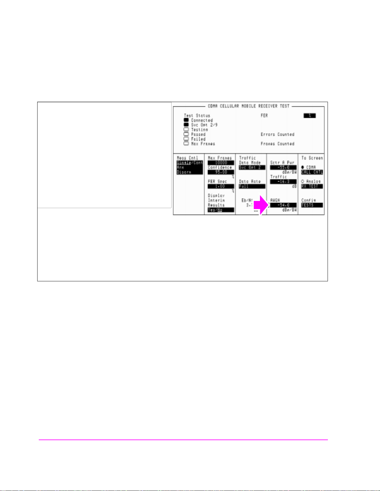
5. Set the AWGN level (test parameter Ioc) .
Manual Operation:
1. Position the cursor at the AWGN field.
2. Press the ON/OFF key.
3. Enter the value recommended by the
appropriate test standards.
Note: If the AWGN value is more than 1 dB
higher in power than the current Sctr A Pwr
setting, the call may drop.
Ioc is defined as the power spectral density of a band-limited white noise source (simulating interference from
other cells) .
HP-IB Syntax
"CDMA:AWGN:STAT ON" !turns the Test Set’s AWGN generator on.
"CDMA:AWGN -54" !sets AWGN to -54 dBM/BW.
64
S:\HPe8285A\APPMOD\BOOK\CHAPTERS\amrcvrt.fb
Page 66

Measuring Demodulation of Forward Traffic Channel with AWGN
6. Verify that the Eb/Nt reading is correct.
Manual Operation:
Refer to the applicable standard for correct Eb/Nt
values.
Eb/Nt is not a user-settable field.
Chapter 3, CDMA Receiver Tests
Eb/Nt is calculated from Sector A Power, AWGN, and the Data Rate. Refer to TIA IS-98 for values.
The resolution of E
as displayed on the Test Set is in hundredths of a dB. TIA IS-98 expresses this value in
b/Nt
tenths of a dB.
HP-IB Syntax
"CDMA:STN?" !queries the Eb/Nt field.
CDMA Receiver Tests
Chapter 3
65
S:\HPe8285A\APPMOD\BOOK\CHAPTERS\amrcvrt.fb
Page 67

Chapter 3, CDMA Receiver Tests
Measuring Demodulation of Forward Traffic Channel with AWGN
7. Set the data rate.
Manual Operation:
1. Position the cursor at the Data Rate field.
2. Press the knob to display a list of choices.
3. Position the cursor at the desired data rate.
(Refer to the applicable standard for
recommended data rate specifications).
4. Press the knob to set the data rate.
Service Option 2 data rate choices are: Full=9600 bps, Half=4800 bps, Quarter=2400 bps, Eighth=1200 bps
Service Option 9 data rate choices are: Full=144 00 bps , Hal f=7 20 0 bps , Qua rter =3 60 0 bps , Eigh t h= 180 0 bp s
When the traffic channel’s data rate is reduced the amount of processing gain is also reduced. To compen sate
for this reduction, Traffic E
HP-IB Syntax
is increased (refer to tables in applicable test standards such as IS-98).
c/Ior
"MEAS:CDMA:CALL:TRAF:DATA:RATE ‘FULL’" !sets the Data Rate to 9600 or
14400 bps, depending on Traffic Data Mode.
66
S:\HPe8285A\APPMOD\BOOK\CHAPTERS\amrcvrt.fb
Page 68

8. Set the FER specification.
Manual Operation:
1. Position the cursor at the FER Spec field.
2. Set the value with the DATA keys. (Refer to the
applicable standard for the recommended FER
specification.
3. Press the ENTER key or the knob to enter the
value.
Chapter 3, CDMA Receiver Tests
Measuring Demodulation of Forward Traffic Channel with AWGN
In the FER Spec field, FER is expr essed in percent. In the applicable stand ard, FER is expressed without units.
Example: If the required FER is 0.03, enter 3 in this field. This will set the maximum number of frame errors
allowed for a passing result at 3%.
Frame errors r esult when the Test Set determines that the frame data it received from th e MSUT does not match
the frame data sent.
HP-IB Syntax
"MEAS:CDM:FER:CONF:LIM 3" !sets the FER to 0.03.
CDMA Receiver Tests
Chapter 3
67
S:\HPe8285A\APPMOD\BOOK\CHAPTERS\amrcvrt.fb
Page 69

Chapter 3, CDMA Receiver Tests
Measuring Demodulation of Forward Traffic Channel with AWGN
9. Setup the display to show interim results (Optional).
Manual Operation:
1. Position the cursor at the Display Interim
Results field.
2. Press the knob to toggle the selection to Yes
Setting up the display to show interim results allows real time observation of FER test results. If you are
interested in ob serving the p rogress of an FER test or the p oint a t w hich frame errors occur, you must select Yes
in the Display Interim Results field.
HP-IB Syntax
.
"DISP:FER:INT:RES ‘YES’"
68
S:\HPe8285A\APPMOD\BOOK\CHAPTERS\amrcvrt.fb
Page 70

10. Arm a single measurement.
Manual Operation:
1. Position the cursor at the Arm field.
2. Press the knob to arm a measurement.
Chapter 3, CDMA Receiver Tests
Measuring Demodulation of Forward Traffic Channel with AWGN
When a measurement is running, the Testing
annunciator will be lit.
HP-IB Syntax
"TRIG:MODE:RETR SING" !selects Single measurement mode.
"TRIG:AST ‘ARM’" !arms the measurement.
CDMA Receiver Tests
Chapter 3
69
S:\HPe8285A\APPMOD\BOOK\CHAPTERS\amrcvrt.fb
Page 71
Chapter 3, CDMA Receiver Tests
Measuring Demodulation of Forward Traffic Channel with AWGN
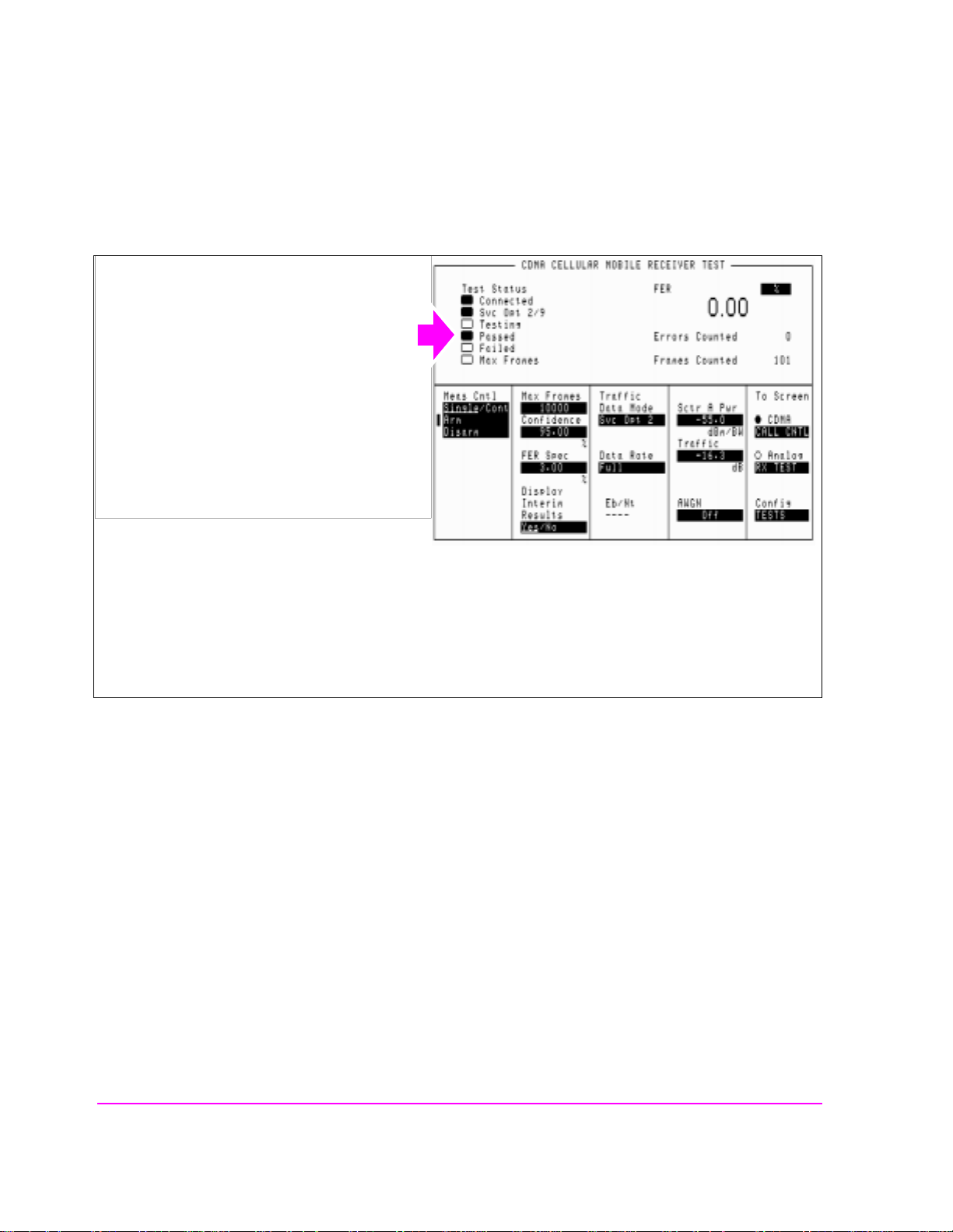
11. Monitor the annunciators to determine test status.
Manual Operation:
The measurement will end when either the
Passed, the Failed, or the Max Frames
annunciator lights.
The Confidence and FER Spec field settings
determine pass/fail criteria. The measurement will end when either the Passed, the Failed, or the Max Frames
annunciator lights.
Turning the Confidence field Off causes the FER test to continue until the number of frames entered in the Max
Frames field are counted. The Max Frames annunciator will light when Frames Counted equals Max Frames.
HP-IB Help Querying the Measuring Status Register condition register bit 0 will indicate
when the FE R test is done.
The following CDMA Status Register event register bits indicate whether a
passed, failed, or max frames result was obtained from an FER test:
• Test Passed (Bit 10, BCD 1024)
• Test Failed (Bit 9, BCD 512)
• Max Frames (Bit 8, BCD 256)
These bits are "event" bits only. No condition registers are implemented. Since
event bits "stick", it is important to clear the register before starting FER test.
Refer to "CDMA Status Register Group" in the Status Reporting chapter of the
HP E8285A User’s Guide for information about using status bits.
70
S:\HPe8285A\APPMOD\BOOK\CHAPTERS\amrcvrt.fb
Page 72

Chapter 3, CDMA Receiver Tests
Measuring Demodulation of Forward Traffic Channel with AWGN
HP-IB Syntax
"STATus:MEASuring:CONDition" !queries the Measuring Status Register condition register. This query can be used to determine if an FER test is
running.
"CDMA:STATus:EVENt?" !queries the CDMA Status Register event register.
This query can be used to determine whether the FER test passed, failed,
or reached max frames.
71
S:\HPe8285A\APPMOD\BOOK\CHAPTERS\amrcvrt.fb
CDMA Receiver Tests
Chapter 3
Page 73

Chapter 3, CDMA Receiver Tests
Measuring Demodulation of Forward Traffic Channel with AWGN
HPBASIC Programming Example
The following programming example was developed using HPBASIC for
Windows. It was tested on an HP E8285A.
10 ! re-save "c:\hpbasic\app_note\FER_AWGN"
20 ! This program implements CDMA FER test with AWGN.
30 ! This closely follows T38 from the 83217A Software.
40 CLEAR SCREEN
50 OUTPUT 714;"CDMA:CALL:END" !End any call currently connected
60 WAIT 1
70 OUTPUT 714;"*RST"
90 Page_phone
100 CLEAR SCREEN
110 Fer_with_awgn
120 DISP "PROGRAM DONE"
130 END
140 Fer_with_awgn: SUB Fer_with_awgn
150 OUTPUT 714;"CDMA:CELL:ASEC:TRAF -16.3dB;PIL -7dB;SYNC -16dB;PAG -12dB"
160 OUTPUT 714;"CDMA:CELL:ASEC:BWP -75 dBm"
170 OUTPUT 714;"CDMA:AWGN:BWP -74 dBm;STAT ON"
180 OUTPUT 714;"TRIG:MODE:RETR SINGLE "
190 OUTPUT 714;"DISP CRXT"
200 OUTPUT 714;"MEAS:CDM:FER:MAX:FRAM 5000"
210 OUTPUT 714;"DISP:FER:INT:RES ’YES’"
220 OUTPUT 714;"MEAS:CDM:FER:CONF:INT 95;INT:STAT ON"
230 OUTPUT 714;"MEAS:CDM:FER:CONF:LIMIT .5"
240 OUTPUT 714;"TRIG:AST ’ARM’"
250 FOR Test=1 TO 6
260 SELECT Test
270 CASE 1
280 OUTPUT 714;"CDMA:CELL:ASEC:TRAF -16.3 DB"
290 OUTPUT 714;"CDMA:CALL:TRAF:DATA:RATE ’FULL’"
300 OUTPUT 714;"MEAS:CDM:FER:CONF:LIM 3"
310 CASE 2
320 OUTPUT 714;"CDMA:CELL:ASEC:TRAF -15.8 DB"
330 OUTPUT 714;"CDMA:CALL:TRAF:DATA:RATE ’FULL’"
340 OUTPUT 714;"MEAS:CDM:FER:CONF:LIM 1"
72
S:\HPe8285A\APPMOD\BOOK\CHAPTERS\amrcvrt.fb
Page 74

Measuring Demodulation of Forward Traffic Channel with AWGN
350 CASE 3
360 OUTPUT 714;"CDMA:CELL:ASEC:TRAF -15.6 DB"
370 OUTPUT 714;"CDMA:CALL:TRAF:DATA:RATE ’FULL’"
380 OUTPUT 714;"MEAS:CDM:FER:CONF:LIM .5"
390 CASE 4
400 OUTPUT 714;"CDMA:CELL:ASEC:TRAF -19.1 DB"
410 OUTPUT 714;"CDMA:CALL:TRAF:DATA:RATE ’HALF’"
420 OUTPUT 714;"MEAS:CDM:FER:CONF:LIM 1"
430 CASE 5
440 OUTPUT 714;"CDMA:CELL:ASEC:TRAF -21.6 DB"
450 OUTPUT 714;"CDMA:CALL:TRAF:DATA:RATE ’QUARTER’"
460 OUTPUT 714;"MEAS:CDM:FER:CONF:LIM 1"
470 CASE 6
480 OUTPUT 714;"CDMA:CELL:ASEC:TRAF -24.5 DB"
490 OUTPUT 714;"CDMA:CALL:TRAF:DATA:RATE ’EIGHTH’"
500 OUTPUT 714;"MEAS:CDM:FER:CONF:LIM 1"
510 END SELECT
520 GOSUB Meas
530 NEXT Test
540 SUBEXIT
550 !
560 Meas:!
570 WAIT 2
580 OUTPUT 714;"TRIG:AST ’ARM’"
590 REPEAT
600 DISP "Measuring FER..."
610 UNTIL FNFer_done
620 OUTPUT 714;"MEAS:CDM:FER?"
630 ENTER 714;Mv
640 Mv=PROUND(Mv,-2) ! Set to 2 significant digits
650 PRINT "Test ";Test;" RXD Traffic Ch FER% is ";Mv
660 RETURN
670 SUBEND
680 Fer_done: DEF FNFer_done
690 WAIT 1
700 OUTPUT 714;"STATUS:CDMA:EVEN?"
710 ENTER 714;Stat
Chapter 3, CDMA Receiver Tests
CDMA Receiver Tests
Chapter 3
73
S:\HPe8285A\APPMOD\BOOK\CHAPTERS\amrcvrt.fb
Page 75

Chapter 3, CDMA Receiver Tests
Measuring Demodulation of Forward Traffic Channel with AWGN
720 IF BIT(Stat,8) THEN RETURN 1
730 IF BIT(Stat,9) THEN RETURN 2
740 IF BIT(Stat,10) THEN RETURN 3
750 RETURN 0
760 FNEND
770 Page_phone: SUB Page_phone
780 OUTPUT 714;"CDMA:CELL:ASEC:BWP -50 dBm;STAT ON"
790 OUTPUT 714;"CDMA:RFCH 384" !
800 PRINT "WHEN THE MOBILE FINDS SERVICE, PRESS THE CONTINUE SOFTKEY (F2)"
810 DISP "Waiting..."
820 PAUSE
830 OUTPUT 714;"CDMA:CALL:TRAF:DATA:MODE ’SVC OPT 2’"
840 OUTPUT 714;"CDMA:CALL:MAKE"
850 DISP "Mobile is being paged..."
860 REPEAT
870 WAIT .1 !100 mS wait to allow Test Set to handle other tasks
880 OUTPUT 714;"STAT:CDMA:EVENT?"
890 ENTER 714;Event_reg
900 UNTIL BIT(Event_reg,3)! Monitoring "Connected" annunciator bit
910 CLEAR SCREEN
920 PRINT "Page successful, mobile is connected"
930 SUBEND
74
S:\HPe8285A\APPMOD\BOOK\CHAPTERS\amrcvrt.fb
Page 76

Chapter 3, CDMA Receiver Tests
Measuring Receiver Sensitivity and Dynamic Range
Measuring Receiver Se ns i tivi t y an d Dyn ami c Ran ge
The Test Set performs "Rece iver Sensitivity and Dynami c Range " a s des cri bed in
TIA IS-98, "CDMA Receiver Minimum Standards."
During this test, FER is measured with the Test Set first providing a low level
signal, then a high level signal in rapid transition. The objective of this test is to
determine if the MSUT can continue to successfully demodulate the forward
traffic channel despite a large change in received power.
NOTE: The following procedure assumes that an instrument PRESET will be performed as part of
setting up a call. This clears all settings from other tests that may affect the accuracy of this
test, and allows the procedure to begin from a known instrument state.
A "HPBASIC Programming Example" on page 85 is provided.
Measurement Overview
For detailed step-by-step explanation see the page associated with the step.
1. "Perform initial setup." on page 76.
2. "Make a Service Option 2 or 9 call." on page 76.
3. "Set the Traffic level (test parameter Traffic Ec/Ior)." on page 77.
4. "Adjust Sector A Power (test parameter Îor )." on page 78.
5. "Set the FER specification." on page 79.
6. "Set the data rate." on page 80.
7. "Setup the display to show interim results (Optional)." on page 81.
8. "Arm a single measurement." on page 82.
9. "Monitor the annunciators to determine test status." on page 83.
CDMA Receiver Tests
Chapter 3
75
S:\HPe8285A\APPMOD\BOOK\CHAPTERS\amrcvrt.fb
Page 77

Chapter 3, CDMA Receiver Tests
Measuring Receiver Sensitivity and Dynamic Range
1. Perform initial setup.
• "Preset the Test Set." on page 49
• "Correct for RF Path Loss." on page 50
• "Enter the MSUT’s Protocol and RF Channel Standard." on page 51
• "Enter the MSUT’s primary CDMA channel." on page 52
• "Adjust Sector A Power. (Optional)" on page 53
• "Save initial settings (Optional)" on page 54
2. Make a Service Option 2 or 9 call.
•"Connect the MSUT to the Test Set." on page 47
•"Turn on power to the MSUT and wait for the MSUT to find digital service." on page
48
•"Select the desired Service Option." on page 49
•"Register the MSUT (Optional)." on page 50
•"Make a call." on page 52
76
S:\HPe8285A\APPMOD\BOOK\CHAPTERS\amrcvrt.fb
Page 78

Measuring Receiver Sensitivity and Dynamic Range
3. Set the Traffic level (test parameter Traffic Ec/Ior).
Manual Operation:
1. Press the CDMA SCREENS - RX test key to
display the CDMA CELLULAR MOBILE
RECEIVER TEST screen.
2. Position the cursor at the Traffic field.
3. Set the value with the DA TA keys. (Refer to the
applicable standard for test parameters).
4. Press the ENTER key or the knob to enter the
value.
Chapter 3, CDMA Receiver Tests
Sector A Pilot Ec/Ior has a factory preset value of
-7 dB. If it is necessary to change this setting, access the CDMA GENERATOR CONTROL screen.
Traffic E
is defined as the ratio of the average transmit energy per PN chip for the Forward Traffic
c/Ior
Channel to the total transmit power spectral density. Values in this field are expressed in dB, relative to
Sctr A Pwr. Energy from the power control sub-channel is not included in Traffic E
c/Ior.
HP-IB Help When the CDMA CELLULAR MOBILE RECEIVER TEST screen is accessed
over the HP-IB, continuous FER measurements are automatically armed.
Unless the
Display Interim Results field is set to Yes, you will not see any
results.
HP-IB Syntax
"CDMA:CELL:ASEC:TRAF -15.6" !sets Sctr A Traffic to -15.6 dB.
CDMA Receiver Tests
Chapter 3
77
S:\HPe8285A\APPMOD\BOOK\CHAPTERS\amrcvrt.fb
Page 79

Chapter 3, CDMA Receiver Tests
Measuring Receiver Sensitivity and Dynamic Range
4. Adjust Sector A Power (test parameter Îor ).
Manual Operation:
1. Position the cursor at the Sctr A Pwr field.
2. Set the value with the DATA keys. (Refer to the
applicable standard for recommended test
parameters).
3. Press the ENTER key or the knob to enter the
value.
The value for Ior is referred to as Sector A Power.
HP-IB Syntax
"CDMA:CELL:ASEC -104" !sets Sctr A Power to -104 dBm/BW.
78
S:\HPe8285A\APPMOD\BOOK\CHAPTERS\amrcvrt.fb
Page 80

5. Set the FER specification.
Manual Operation:
1. Position the cursor at the FER Spec field.
2. Set the value with the DATA keys. (Refer to the
applicable standard for recommended FER
specification.
3. Press the ENTER key or the knob to enter the
value.
Chapter 3, CDMA Receiver Tests
Measuring Receiver Sensitivity and Dynamic Range
In the FER Spec field, FER is expressed in percent.
In the TIA IS-98 standards, FER is expressed without units. Example: If the TIA IS-98 required FER is 0.005,
enter 0.5 in this field.
Frame errors result wh en the Test Set determines that the frame data it received from the MSUT does not match
the frame data sent.
HP-IB Syntax
"MEAS:CDM:FER:CONF:LIM 0.5"
CDMA Receiver Tests
Chapter 3
79
S:\HPe8285A\APPMOD\BOOK\CHAPTERS\amrcvrt.fb
Page 81

Chapter 3, CDMA Receiver Tests
Measuring Receiver Sensitivity and Dynamic Range
6. Set the data rate.
Manual Operation:
1. Position the cursor at the Data Rate field.
2. Press the knob to display a list of choices.
3. Position the cursor at the desired data rate.
(Refer to the applicable standard for
recommended data rate specifications.
4. Press the knob to set the data rate.
Service Option 2 data rate choices are: Full=9600 bps, Half=4800 bps, Quarter=2400 bps, Eighth=1200 bps
Service Option 9 data rat e choi ces are: Full=14400 bps, Half=7200 bps, Quarte r =3600 bps , Ei gh t h=180 0 bps
When the traffic channel’s data rate is reduced the amount of processing gain is also reduced. To compensate
for this reduction, Traffic E
is increased (refer to tables in applicable test standards such as IS-98).
c/Ior
HP-IB Syntax
"MEAS:CDMA:CALL:TRAF:DATA:RATE ‘FULL’"
80
S:\HPe8285A\APPMOD\BOOK\CHAPTERS\amrcvrt.fb
Page 82
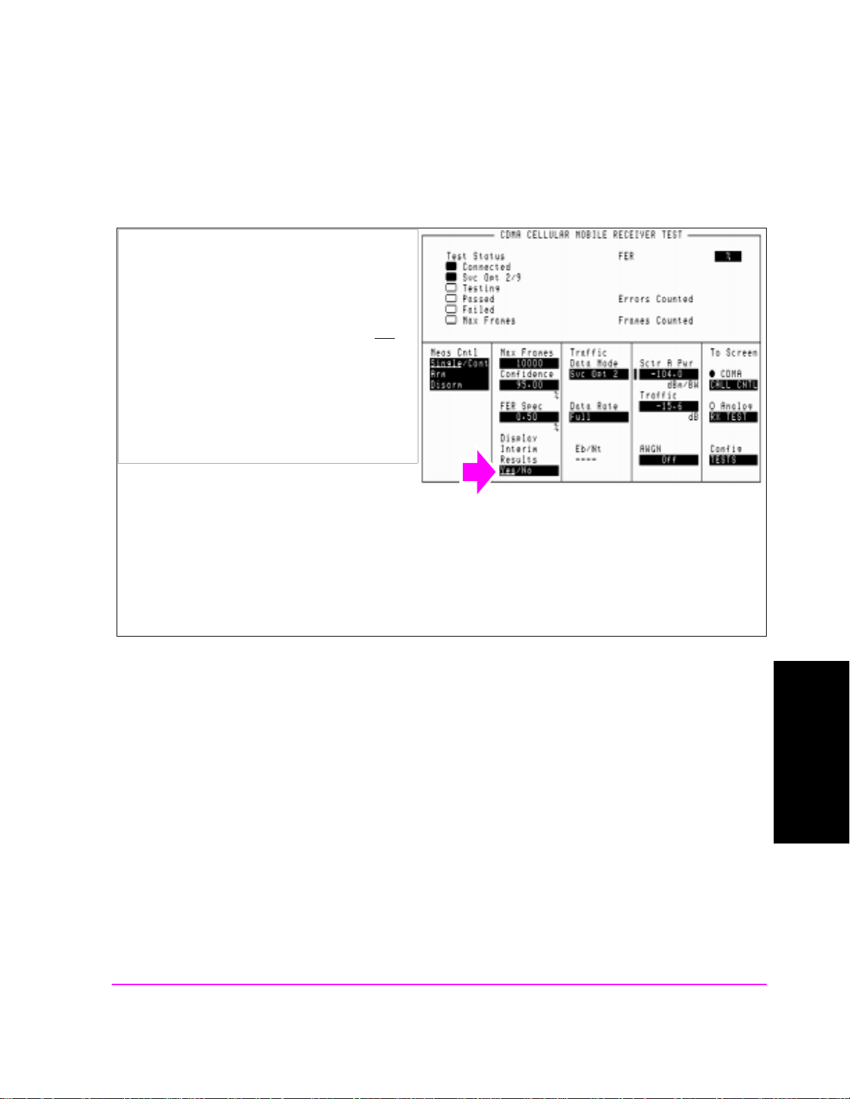
Measuring Receiver Sensitivity and Dynamic Range
7. Setup the display to show interim results (Optional).
Manual Operation:
1. Position the cursor at the Display Interim
Results field.
Chapter 3, CDMA Receiver Tests
2. Press the knob to toggle the selection to Yes
.
Setting up the display to show interim results allows real time observation of FER test results. If you are
interested in ob serving the p rogress of an FER test or the p oint a t w hich frame errors occur, you must select Yes
in the Display Interim Results field.
HP-IB Syntax
"DISP:FER:INT:RES ‘YES’"
CDMA Receiver Tests
Chapter 3
81
S:\HPe8285A\APPMOD\BOOK\CHAPTERS\amrcvrt.fb
Page 83
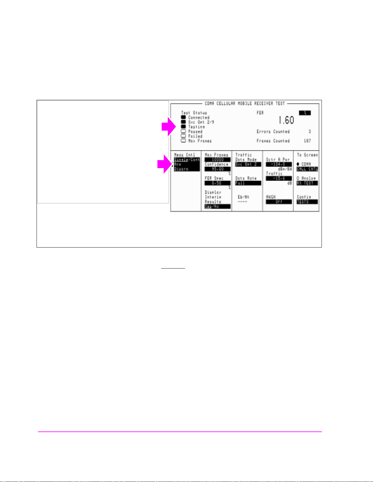
Chapter 3, CDMA Receiver Tests
Measuring Receiver Sensitivity and Dynamic Range
8. Arm a single measurement.
Manual Operation:
1. Position the cursor at the Arm field.
2. Press the knob to arm a test.
When a measurement is running, the Testing
annunciator will be lit.
HP-IB Syntax
"TRIG:MODE:RETR SING" !selects Single measurement mode.
"TRIG:AST ‘ARM’" !starts the FER measurement.
"TRIG" !starts the FER measurement and other "active" measurements.
82
S:\HPe8285A\APPMOD\BOOK\CHAPTERS\amrcvrt.fb
Page 84
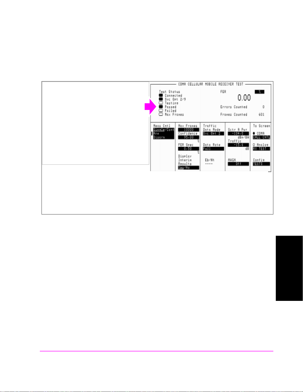
Measuring Receiver Sensitivity and Dynamic Range
9. Monitor the annunciators to determine test status.
Manual Operation:
The measurement will end when either the
Passed, the Failed, or the Max Frames
annunciator lights.
Chapter 3, CDMA Receiver Tests
The Confidence and FER Spec field settings
determine pass/fail criteria. The measurement will end when either the Passed, Failed, or Max Frames
annunciator lights.
Turning the Confidence field off will force the measur ement to continue until the number of frames entered in the
HP-IB Help Querying the Measuring Status Register condition register bit 0 will indicate
when the FE R test is done.
The following CDMA Status Register event register bits indicate whether a
passed, failed, or max frames result was obtained from an FER test:
• Test Passed (Bit 10, BCD 1024)
• Test Failed (Bit 9, BCD 512)
• Max Frames (Bit 8, BCD 256)
These bits are "event" bits only. No condition registers are implemented. Since
event bits "stick", it is important to clear the register before starting FER test.
Refer to "CDMA Status Register Group" in the Status Reporting chapter of the
HP E8285A User’s Guide for information about using status bits.
CDMA Receiver Tests
Chapter 3
83
S:\HPe8285A\APPMOD\BOOK\CHAPTERS\amrcvrt.fb
Page 85

Chapter 3, CDMA Receiver Tests
Measuring Receiver Sensitivity and Dynamic Range
HP-IB Syntax
"STATus:MEASuring:CONDition" !queries the Measuring Status Register condition register. This query can be used to determine if an FER test is
running.
"CDMA:STATus:EVENt?" !queries the CDMA Status Register event register.
This query can be used to determine whether the FER test passed, failed,
or reached max frames.
84
S:\HPe8285A\APPMOD\BOOK\CHAPTERS\amrcvrt.fb
Page 86

Chapter 3, CDMA Receiver Tests
Measuring Receiver Sensitivity and Dynamic Range
HPBASIC Programming Example
The following programming example was developed using HPBASIC for
Windows. It was tested on an HP E8285A with firmware rev A.02.26.
10 ! re-save "c:\hpbasic\Sens_rng"
20 ! This program implements CDMA RX Sensitivity and Dynamic Range"
30 This closely follows T39 from the 83217A Software.
40 Initialize_ts
50 OUTPUT 714;"TRIG:MODE:RETR SINGLE"
60 Page_phone
70 CLEAR SCREEN
80 Sensitivity_rng
90 OUTPUT 714;"CDMA:CALL:END"
100 DISP "PROGRAM DONE"
110 END
120 Sensitivity_rng: SUB Sensitivity_rng
130 DISP "Measuring mobile sensitivity"
140 OUTPUT 714;"CDMA:CELL:ASEC:PIL -7dB;SYNC -16dB"
145 OUTPUT 714;"CDMA:CELL:ASEC:PAG -12dB;TRAF -15.6dB"
150 OUTPUT 714;"CDMA:CELL:ASEC:BWP -90 dBm"
160 OUTPUT 714;"CDMA:CELL:ASEC:BWP -104 dBm"
170 OUTPUT 714;"DISP CRXT"
180 OUTPUT 714;"MEAS:CDM:FER:MAX:FRAM 5000"
190 OUTPUT 714;"MEAS:CDM:FER:STAT ON"
200 OUTPUT 714;"MEAS:CDM:FER:CONF:INT 95;INT:STAT ON"
210 OUTPUT 714;"MEAS:CDM:FER:CONF:LIMIT .5"
220 GOSUB Meas ! Sensitivity test
230 Lvl=-25
240 OUTPUT 714;"CDMA:CELL:ASEC:BWP -25 dBm"
250 GOSUB Meas
260 SUBEXIT
270 Meas: !
280 Arm_fer
290 Max_f=0
300 P_f=0
310 Cnt=0
320 REPEAT
CDMA Receiver Tests
Chapter 3
85
S:\HPe8285A\APPMOD\BOOK\CHAPTERS\amrcvrt.fb
Page 87

Chapter 3, CDMA Receiver Tests
Measuring Receiver Sensitivity and Dynamic Range
330 Cnt=Cnt+1340 UNTIL FNFer_done(Mv,P_f,Max_f) OR Cnt>125
350 IF Cnt>125 THEN
360 PRINT "Sensitivity test timed out"
370 ELSE
380 Mv=PROUND(Mv,-2)
390 PRINT "RXD Sensitivity FER% = ";Mv
400 END IF
410 RETURN
420 SUBEND
430 Fer_done: DEF FNFer_done(Mv,P_f,Max_f)
440 WAIT 1
450 OUTPUT 714;"STATUS:MEAS:CONDITION?"
460 ENTER 714;Meas
470 OUTPUT 714;"MEAS:CDM:FER?"
480 ENTER 714;Mv
490 IF BIT(Meas,0) THEN RETURN 0 ! Not done
500 OUTPUT 714;"STATUS:CDMA?"
510 ENTER 714;Stat
520 IF BIT(Stat,8) THEN Max_f=1
530 IF BIT(Stat,10) THEN P_f=1
540 RETURN 1
550 FNEND
560 Arm_fer: SUB Arm_fer
570 OUTPUT 714;"TRIG"
580 REPEAT
590 WAIT .1
600 OUTPUT 714;"STATUS:MEAS:CONDITION?"
610 ENTER 714;Meas
620 UNTIL BIT(Meas,0)
630 SUBEND
640 Page_phone: SUB Page_phone
650 OUTPUT 714;"CDMA:CELL:ASEC:BWP -50 dBm;STAT ON"
660 OUTPUT 714;"CDMA:RFCH 384" !
670 PRINT "WHEN THE MOBILE FINDS SERVICE, PRESS"
675 PRINT "THE CONTINUE SOFTKEY (F2)"
680 DISP "Waiting..."
690 PAUSE
86
S:\HPe8285A\APPMOD\BOOK\CHAPTERS\amrcvrt.fb
Page 88

Chapter 3, CDMA Receiver Tests
Measuring Receiver Sensitivity and Dynamic Range
700 OUTPUT 714;"CDMA:CALL:TRAF:DATA:MODE ’SVC OPT 2’"
710 OUTPUT 714;"CDMA:CALL:MAKE"
720 DISP "Mobile is being paged..."
730 REPEAT
740 WAIT .1 !100 mS wait to allow Test Set to handle other tasks
750 OUTPUT 714;"STAT:CDMA:EVENT?"
760 ENTER 714;Event_reg
770 UNTIL BIT(Event_reg,3)! Monitoring "Connected" annunciator bit
780 CLEAR SCREEN
790 PRINT "Page successful, mobile is connected"
800 SUBEND
810 Initialize_ts: SUB Initialize_ts
820 CLEAR 714
830 CLEAR SCREEN
840 DISP "Initializing...."
850 OUTPUT 714;"*RST"! Reset
860 WAIT 5
870 OUTPUT 714;"CONF:OFL:MODE ’ON’;RFIN -2"! External Path Loss
880 SUBEND
87
S:\HPe8285A\APPMOD\BOOK\CHAPTERS\amrcvrt.fb
CDMA Receiver Tests
Chapter 3
Page 89

Chapter 3, CDMA Receiver Tests
Measuring Single Tone Desensitization
Measuring Single Tone Desensitization
The Test Set performs the necessary call processing and FER measurements for
"Single Tone Desensitization," but requires a single external continuous wave
(CW) signal generator to perform this test as described in TIA IS-98, "CDMA
Receiver Minimum Standards."
During thi s test, an interfering signal (tone) is summed with the Test Set’s output
and the FER is measured. The objective of this test is to measure the MSUT
receiver’s ability to perform when adjacent channel interference is present.
"Programming Example" on page 102 is provided.
A
Measurement Overview
1. "Perform initial setup." on page 89.
2. "Connect the test equipment as shown." on page 90.
3. "Make a Service Option 2 or 9 call." on page 91.
4. "Set the signal generator’s interfering tone to the required frequency and ampli-
tude." on page 92.
5. "Turn the Signal Generators amplitude On." on page 9 3.
6. "Set the Traffic level (test parameter Traffic Ec/Ior)." on page 94.
7. "Adjust Sector A Power (test parameter Îor )." on page 95.
8. "Set the FER specification." on page 96.
9. "Set the data rate." on page 97.
10. "Set up display to show interim results (Optional)." on page 98.
11. "Arm a single measurement." on page 99.
12. "M onitor the annun ciators to determine test status." on page 100.
Recommended Equipment
CW Generator Specifications for the CW signal generator are provided in TIA IS-98, "CDMA
Standard Test Conditions." At the time of this printing, the following signal
generators meet these specifications:
• HP 8657D
• HP 8656B
• HP 8647A
Combiner
The Combiner used in this test must provide adequate isolation between the
Signal Generator output and the signals generated by the MSUT and the Test Set.
At least 15 dB isolation is recommended.
88
S:\HPe8285A\APPMOD\BOOK\CHAPTERS\amrcvrt.fb
Page 90

1. Perform initial setup.
• "Preset the Test Set." on page 49
• "Correct for RF Path Loss." on page 50
• "Enter the MSUT’s Protocol and RF Channel Standard." on page 51
• "Enter the MSUT’s primary CDMA channel." on page 52
• "Adjust Sector A Power. (Optional)" on page 53
• "Save initial settings (Optional)" on page 54
Chapter 3, CDMA Receiver Tests
Measuring Single Tone Desensitization
89
S:\HPe8285A\APPMOD\BOOK\CHAPTERS\amrcvrt.fb
CDMA Receiver Tests
Chapter 3
Page 91

Chapter 3, CDMA Receiver Tests
Measuring Single Tone Desensitization
2. Connect the test equipment as shown.
RF IN/OUT
Test Set
Combiner
MSUT
RX/TX
Connect the equipment as shown, but make sure the Signal Generator amplitude is turned of f . T his signal, if
turned on, may interfere with making a call during the next step.
Σ
RF OUT
Amplitude Off
Signal Generator
90
S:\HPe8285A\APPMOD\BOOK\CHAPTERS\amrcvrt.fb
Page 92

3. Make a Service Option 2 or 9 call.
•"Connect the MSUT to the Test Set." on page 47
•"Turn on power to the MSUT and wait for the MSUT to find digital service." on page
48
•"Select the desired Service Option." on page 49
•"Register the MSUT (Optional)." on page 50
•"Make a call." on page 52
Chapter 3, CDMA Receiver Tests
Measuring Single Tone Desensitization
91
S:\HPe8285A\APPMOD\BOOK\CHAPTERS\amrcvrt.fb
CDMA Receiver Tests
Chapter 3
Page 93

Chapter 3, CDMA Receiver Tests
Measuring Single Tone Desensitization
4. Set the signal generator’s interfering tone to the required frequency and amplitude.
Manual Operation:
Refer to app licable stand ard for test
parameters.
To display the forward link carrier frequency that the mobile station is assigned to receive,
1. Press the Config key to select the CONFIGURE screen.
2. Select Freq
3. Press the CDMA SCREENS Call control key.
The forward link (from the Test Set) carrier frequency will be dis played in the RF Gen Freq field.
in the RF Display field.
-30.01955.9000000
92
S:\HPe8285A\APPMOD\BOOK\CHAPTERS\amrcvrt.fb
Page 94

5. Turn the Signal Generators amplitude On.
Test Set
RF IN/OUT
Chapter 3, CDMA Receiver Tests
Measuring Single Tone Desensitization
MSUT
Combiner
RX/TX
Σ
RF OUT
-30 dBm
+ 900 kHz
f
c
Signal Generator
CDMA Receiver Tests
Chapter 3
93
S:\HPe8285A\APPMOD\BOOK\CHAPTERS\amrcvrt.fb
Page 95

Chapter 3, CDMA Receiver Tests
Measuring Single Tone Desensitization
6. Set the Traffic level (test parameter Traffic Ec/Ior).
Manual Operation:
1. Press the CDMA SCREENS - RX Test key to
display the CDMA CELLULAR MOBILE
RECEIVER TEST screen.
2. Position the cursor at the Traffic field.
3. Set the value with the DATA keys. (Refer to the
applicable standard for test parameters).
4. Press the ENTER key or knob to enter the
value.
Values in this field are expressed in dB, r elative to
Sctr A Pwr.
Sctr A Pilot E
has a factory preset value of -7 dB. If it is necessary to change this setting, access the CDMA
c/Ior
GENERATOR CONTROL screen.
HP-IB Help When the CDMA CELLULAR MOBILE RECEIVER TEST screen is accessed
over the HP-IB, continuous FER measurements are automatically armed.
Unless the
Display Interim Results field is set to Yes, you will not see any
results.
HP-IB Syntax
"DISP CRXT" !displays the CDMA CELLULAR MOBILE RECEIVER TEST screen.
"CDMA:CELL:ASEC:TRAF -15.6" !sets Sctr A Traffic Ec/Ior to -15.6 dB
94
S:\HPe8285A\APPMOD\BOOK\CHAPTERS\amrcvrt.fb
Page 96
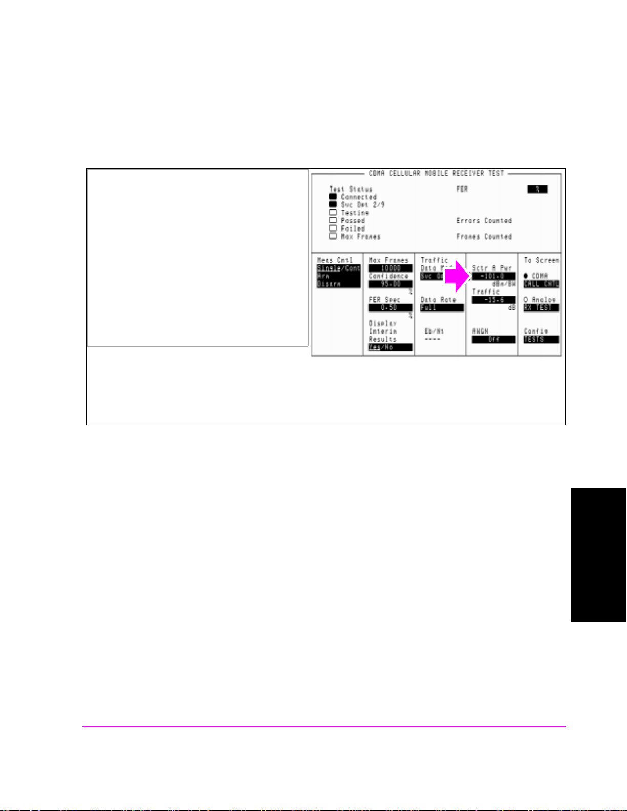
7. Adjust Sector A Power (test parameter Îor ).
Manual Operation:
1. Position the cursor at the Sctr A Pwr field.
2. Set the value with the DATA keys. (Refer to the
applicable standard for test parameters).
3. Press the ENTER key or the knob to enter the
value.
Chapter 3, CDMA Receiver Tests
Measuring Single Tone Desensitization
The value for Sector A Power is referred to as Ior .
HP-IB Syntax
"CDMA:CELL:ASEC -101" !sets Sctr A Ior to -101 dBm/BW
CDMA Receiver Tests
Chapter 3
95
S:\HPe8285A\APPMOD\BOOK\CHAPTERS\amrcvrt.fb
Page 97

Chapter 3, CDMA Receiver Tests
Measuring Single Tone Desensitization
8. Set the FER specification.
Manual Operation:
1. Position the cursor at the FER Spec field.
2. Set the value with the DATA keys. (Refer to the
applicable standard for the recommended FER
specification.
3. Press the ENTER key or the knob to enter the
value.
In the FER Spec field, FER is expressed in percent. In the TIA IS-98 standards, FER is expressed without
units. Example: If the TIA IS-98 required FER is 0.01, enter a value of 1.00 in this field.
Frame errors result when the Test Set determines that the frame data it received from the MSUT does not
match the frame data sent.
HP-IB Syntax
"MEAS:CDM:FER:CONF:LIM 1" !sets the FER specification to 1%.
96
S:\HPe8285A\APPMOD\BOOK\CHAPTERS\amrcvrt.fb
Page 98
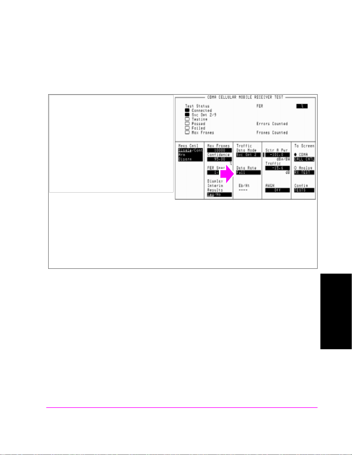
9. Set the data rate.
Manual Operation:
1. Position the cursor at the Data Rate field.
2. Press the knob to display a list of choices.
3. Position the cursor at the desired data rate.
(Refer to the applicable standard for
recommended data rate specifications.)
4. Press the knob to set the data rate.
Chapter 3, CDMA Receiver Tests
Measuring Single Tone Desensitization
Service Option 2 data rate choices are: Full=9600 bps, Half=4800 bps, Quarter=2400 bps, Eighth=1200 bps
Service Option 9 data ra te choices are: Ful l =144 00 bps, Half=7200 bps , Quar t er= 3 600 bps , Ei gh th = 180 0 bp s
When the traffic channel’s data rate is reduced the amount of processing gain is also reduced. To compensate
for this reduction, Traffic E
is increased (refer to tables in applicable test standards such as IS-98).
c/Ior
HP-IB Syntax
"MEAS:CDMA:CALL:TRAF:DATA:RATE ‘FULL’" !sets the data rate to 9600 bps (for Svc Opt 2)
or 14400 bps (for Svc Opt 9).
CDMA Receiver Tests
Chapter 3
97
S:\HPe8285A\APPMOD\BOOK\CHAPTERS\amrcvrt.fb
Page 99

Chapter 3, CDMA Receiver Tests
Measuring Single Tone Desensitization
10. Set up display to show interim results (Optional).
Manual Operation:
1. Position the cursor at the Display Interim
Results field.
2. Press the knob to toggle the selection to Yes
.
Setting up the display to show interim results allows real time observation of FER test results. If you are
interested in ob serving the p rogress of an FER test or the p oint a t w hich frame errors occur, you must select Yes
in the Display Interim Results field.
HP-IB Syntax
"DISP:FER:INT:RES ‘YES’" !displays interim FER test results.
98
S:\HPe8285A\APPMOD\BOOK\CHAPTERS\amrcvrt.fb
Page 100

11. Arm a single measurement.
Manual Operation:
1. Position the cursor at the Arm field.
2. Press the knob to arm a measurement.
Chapter 3, CDMA Receiver Tests
Measuring Single Tone Desensitization
When a measurement is running, the Testing
annunciator will be lit.
HP-IB Syntax
"TRIG:MODE:RETR SING" !selects Single measurement mode.
"TRIG:AST ‘ARM’" !arms the measurement.
CDMA Receiver Tests
Chapter 3
99
S:\HPe8285A\APPMOD\BOOK\CHAPTERS\amrcvrt.fb
 Loading...