

Page 1

Agilent Technologies E8285A CDMA
Mobile Station Test Set
Assembly Level Repair
Firmware Version: A.01.29 to A.02.04 (100-1000, 1700-2000 MHz)
Firmware Version: A.04.53 and above (800-1000, 1700-2000 MHz)
CALL CONTROL UTILITIES
Answer Print Printer I/O config Help
Call/
End/
Page
USER
K1'
K1
K2'
K2
K3'
K3
Assign
K4
Release
K5
Shift
Register Tests Config Previous Message
Release
CDMA SCREENS
Cell config Spectrum SMS
Call
Gen
control
MS report MS FER
RX test
Ref set
Increment
10
Low limit
IBASIC
reset
Cancel
Authen-
control
tication
TX test
TX
range
DATA FUNCTIONS DATA
Meter
Average
Increment
Increment
set
x 10
High limit
ANALOG SCREENS
Call
Duplex Spectrun
control
RX test TX test AF
7 8 9
4 5 6
1 2 3
0 . +/-
Yes
No
Ratio
On/Off
W
DUPLEX OUTRF IN/OUTPOWER ANTENNA IN VOLUME AUDIO OUT AUDIO IN
analyzer
analyzer
%dBHz
High
Preset
Hold
Meas
reset
Address
Local
Save
Recall
Enter
Ghz
dBm
dB
MHz
V
%
kHz
mV
s
mW
µV
ms
Low
DO NOT apply RF
when in standby
Max power 2.5W
Max power 60 mW Max 12V peak Max
Agilent Part Number E8285-90033
Revision C
Printed in U.S.A.
June 2000
42V peak
Page 2

Notice
Information contained in this document is subject to change without
notice.
All Rights Reserved. Reproduction, adaptation, or translation without
prior written permission is prohibited, except as allowed under the
copyrigh t laws.
This material may be reproduced by or for the U.S. Government
pursuant to the Copyright License under the cl ause at DFARS
52.227-7013 (APR 1988).
© Copyright 2000 Agilent Technologies
2
S:\agilent\e8285\ALR\Book\chapters\front.fm
Page 3

Manufacturer’s Declaration
This statement is provided to comply with the requirements of the
German Sound Emission Directive, from 18 January 1991.
This product has a sound pres sur e emission ( at t he ope rato r posit ion) <
70 dB(A).
• Sound Pressure Lp < 70 dB(A).
• At Operator Position.
• Normal Operation.
• According to ISO 7779:1988/EN 27779:1991 (Type Test).
Herstellerbescheinigung
Diese Information steht im Zusammenhang mit den Anf orderungen der
Maschinenlärminformationsverordnung vom 18 Januar 1991.
• Schalldruckpegel Lp < 70 dB(A).
•Am Arbeitsplatz.
• Normaler Betr i e b.
• Nach ISO 7779:1988/EN 27779:1991 (Typprüfung).
3
Page 4

Safety Considerations
!
GENERAL
This product and related documentation must be reviewed for
familiarization with safety markings and instructions before operation.
This product has been designed and tested in accordance with IEC
Publication 1010, “Safety Requirements for Electronic Measuring
Apparatus,” and has been s u pplied in a safe condition. This instruction
documentation contains information and warnings which must be
followed by the user to ensure safe operation and to maintain the
product in a safe condition.
SAFETY EARTH GROUND
A uninterruptible safety earth ground must be provided fro m the main
power source to the product input wiring terminals, power cord, or
supplied power cord set.
CHASSIS GROUND TERMINAL
To prevent a potential shock hazard, always connect the rear -panel
chassis ground terminal to earth ground when operating this
instrument from a dc power source.
SAFETY SYMBOLS
Indicates instrument damage can occur if indicated oper ating limits are
exceeded. Refer to the instructions in this guide.
Indicates hazardous voltages.
Indicates earth (ground) terminal
WARNING A W ARNING note denotes a hazard. It calls attention to a
procedure, practice, or the like, which, if not correctly
performed or adhered to, could result in personal injury. Do not
proceed beyond a W ARNING s ign until the indicated conditi ons
are fully understood and met.
CAUTION A CAUTION note denotes a hazard. It calls attention to an operation
procedure, practic e, or the like, which, if not correctly performed or
adhered to, could result in damage to or destruction of part or all of t he
product. Do not proceed beyond an CAUTION note until the indicated
conditions are fully understood and met .
4
S:\agilent\e8285\ALR\Book\chapters\front.fm
Page 5

Safety Considerations for this Instrument
WARNING This product is a Safety Class I instrument (provided with a
protective earthing ground incorporated in the power cord). The
mains plug shall only be inserted in a socket outlet provided with a
protective earth contact. Any interruption of the protective conductor
inside or outside of the product is li kely to make the product
dangerous. Intentional interruption is prohibited.
Whenever it is likely that the protection has been impaired, the
instrument must be made inoperative and be secured against any
unintended operation.
If this instrument is to be energized via an autotransformer (for
voltage reduction), make sure the common terminal is connected to
the earth terminal of the power source.
If this product is not us ed as specified, the protec tion provid ed by t he
equipment could be impaired. This product must be used in a normal
condition (in which all means for protection are intact) only.
No operator serviceable parts in this product. Refer servicing to
qualified personnel. To prevent electrical shock, do not remove
covers.
Servicing instructions are for use by qualified personnel only. To
avoid electrical shock, do not perform any servicing unless you are
qualified to do so.
The opening of covers or removal of parts is likely to expose
dangerous voltages. Disconnect the product from all voltage sources
while it is being opened.
Adjustments described in the manual are performed with power
supplied to the instrument while protective covers are removed.
Energy available at many points may, if contacted, result in personal
injury.
The power cord is connected to internal capacitors that my remain
live for 5 seconds after disconnecting the plug from its power supply.
For Continued protection against fire hazard, replace the line fuse(s)
only with 250 V fuse(s) or the same current rating and type (for
example, normal blow or time delay). Do not use repaired fuses or
short circuited fuseholder s.
5
Page 6

CAUTION Always use the three -prong ac power cord supplied with this product.
Failure to ensure adequate earth grounding by not using this cord may
cause product damage.
This product is designed for use in Installation Category II and
Pollution Degree 2 per IEC 1010 and IEC 664 respectively. For indoor
use only.
This product has autoranging line voltage input, be sure the supply
voltage is within the specified range.
V entilation Require ments: When installing the prod uct in a cabinet, the
convection into and out of the product must not be restri cted. The
ambient temperature (outside the cabinet) must be less than the
maximum operating temperature of the product by 4° C for every 100
watts dissipated in the cabinet. If the total power dissipated in the
cabinet is greater than 800 watts, then forced convection must be used.
6
S:\agilent\e8285\ALR\Book\chapters\front.fm
Page 7

Product Markings
CE - the CE mark is a registered trademark of the European
Community. A CE mark accompanied by a year indicated the year the
design was proven.
CSA - the CSA mark is a registered trademark of the Canadian
Standards Association.
7
Page 8

Agilent Technologies Warranty Statement
for Commercial Products
E8285A CDMA Mobile Station T es t Set
Duration of Warranty: One Year
1. Agilent warrants Ag ilent hardwar e, a ccessories and supplies aga inst
defects in materials and workmans hip for the period sp ecified above .
If Agilent receives notice of such defect s during the w arranty peri od,
Agilent will, at its option, either repair or replace products which
prove to be defective. Replacement prod ucts may be either new or
like-new.
2. Agilent warrants that Agilent software will not fail to execute its
programming instructions, for the period specified above, due to
defects in material and workmanshi p when properly installed and
used. If Agi l en t re ceives notic e o f su ch d e fe cts during the war ra n ty
period, Agilent will replace softwa re media which does not execute
its programming instructions due to such defects.
3. Agilent does not warrant that the operation of Agilent products will
be uninterrupted or error free. If Agilent is unable, within a
reasonable time, to repair or replace any product to a condition as
warranted, customer will be enti tled to a refund of the purchase
price upon prompt return of the product.
4. Agilent products may contain remanufactured parts equivalent to
new in performance or may have been subject to incident al use.
5. The warranty period begins on the date of delivery or on the date of
installation if installed by Agilent. If customer schedules or delays
Agilent installation more than 30 days after delivery, warranty
begins on the 31st day from delivery.
6. Warranty does not apply to defects resulting from (a) improper or
inadequate maintenance or calibration, (b) sof tware, interfacing,
parts or supplies not supplied by Agilent, (c) unauthorized
modification or misuse, (d) operation outside of the published
environmental specifications for the product, or (e) improper site
preparation or maintenance.
7. TO THE EXTENT ALLOWED BY LOCAL LAW, THE ABOVE
WARRANTIES ARE EXCLUSIVE AND NO OTHER WARRANTY
OR CONDITION, WHETHER WRITTEN OR ORAL IS
EXPRESSED OR IMPLIED AND AGILENT SPECIFICALLY
DISCLAIMS ANY IMPLIED WARRANTIES OR CONDITIONS OR
MERCHANTABILITY, SATISFACTORY QUALITY, AND FITNESS
FOR A PARTICULAR PURPOSE.
8
S:\agilent\e8285\ALR\Book\chapters\front.fm
Page 9

8. Agilent will be liable for damage to tangibl e property per incident up
to the greater of $300,000 or the actual amount paid for the product
that is the subject of the claim, and for damages for bodily injury or
death, to the extent that all suc h damages are d etermined by a cou rt
of competent jurisdiction to have been directly caused by a defective
Agilent product.
9. TO THE EXTENT ALLOWED BY LOCAL LAW, THE REMEDIES
IN THIS WARRANTY STATEMENT ARE CUSTOMER’S SOLE
AND EXCLUSIVE REMEDIES. EXCEPT AS INDICATED ABOVE,
IN NO EVENT WILL AGILENT OR ITS SUPPLIERS BE LIABLE
FOR LOSS OF DATA OR FOR DIRECT, SPECIAL, INCIDENTAL,
CONSEQUENTIAL (INCLUDING LOST PROFIT OR DATA), OR
OTHER DAMAGE, WHETHER BASED IN CONTRACT, TORT, OR
OTHERWISE.
FOR CONSUMER TRANSACTIONS IN AUSTRALIA AND NEW
ZEALAND: THE WARRANTY TERMS CONTAINED IN THIS
STATEMENT, EXCEPT TO THE EXTENT LAWFULLY
PERMITTED, DO NOT EXCLUDE RESTRICT OR MODIFY AND
ARE IN ADDITION TO THE MANDATORY STATUTORY RIGHTS
APPLICABLE TO THE SALE OF THIS PRODUCT TO YOU.
9
Page 10

DECLARATION OF CONFORMITY
according to ISO/IEC Guide 22 and EN 45014
Manufacturer’s Name:
Agilent Technologies
Manufacturer’s Address:
Spokane Division
24001 E. Mission Avenue
Liberty Lake, Washington 99019-9599
USA
declares that the product
Product Name:
Model Number:
Product Options:
CDMA Mobile Station Test Set
Agilent Technologies E8285A
All
conforms to the following Product specifications:
Safety: IEC 61010-1:1990+A1+A2 / EN 61010-1:1993+A2
EMC: CISPR 11:1990/EN 55011:1991- Group 1, Class A
IEC 61000-3-2:1995 / EN 61000-3-2: 1995
EN 50082-1:1992
IEC 801-3:1984 3V/m
IEC 801-4:1988 0.5 kV Sig. Lines, 1 kV Power Lines
Supplementary Information:
This product herewith complies with the requirements of
the Low Voltage Directive 73/23/EEC and the EMC
Directive 89/336/EEC and carries the CE-marking
accordingly.
Spokane, Washington USA November 20, 1998
European Contact: Your local Agilent Technologies and Service Office or Agilent Technologies GmbH
Department ZQ/Standards Europe, Herrenbe rger Strasse 130, D-71034 Böbl inger, Germany (FAX+49-7031-14-3143)
10
Vince Roland
Reliability & Regulatory
Engineeri ng Manager
S:\agilent\e8285\ALR\Book\chapters\front.fm
Page 11

Table 1
United States of America:
Agilent Technologies
Test and Measurement Call
Center
P.O. Box 4026
Englewood, CO 80155-4026
(tel) 1 800 452 4844
Japan:
Agilent Technologies Japan Ltd.
Measurement Assistance Center
9-1 Takakura-Cho, Hachioji-Shi,
Tokyo 192-8510, Japan
(tel) (81) 456-56-7832
(fax) (81) 426-56-7840
Asia Pacific:
Agilent Technologies
19/F, Cityplaz a One,
111 Kings Road,
Taikoo shing, Hong Kong, SAR
Canada:
Agilent Technologies
Canada Inc.
5159 Spectrum Way
Mississauga, Ont ar io
L4W 5G1
(tel) 1 877 894 4414
Latin America:
Agilent Technologies
Latin America Region
Headquarters
5200 blue Lagoon Drive,
Suite #950
Miami, Florida 33126
U.S. A.
(tel) (305) 267 4245
(fax) (305) 267 4286
Europe:
Agilent Technologies
European Marketing
Organization
P.O. Box 999
1180 AZ Amstelveen
The Netherlands
(tel) (3120) 547 9999
Australia/New Zealand:
Agilent Technologies
Australia Pty Ltd
347 Burwood Highway
Forest Hill, Victoria 3131
(tel) 1 800 629 485 (Australia)
(fax) (61 3) 9272 0749
(tel) 0 800 738 378 (New
Zealand)
(fax) (64 4) 802 6881
(tel) (852) 2599 7899
(fax) (852) 2506 9233
11
Page 12

Agilent Technologies E8285A Support
Contacts
The documentation supplied with your Test Set is an excellent source of
reference, application, and service information. Please use these
manuals if you are experiencing technical problems:
Table 2 Support Documentation
User’s Guide Quick Reference Guide
Application Guide Assembly Level Repair
Reference Guide CD-ROM
If you have used the manuals and still have application questions,
contact your local Agilent Technologies Sales Representative.
Repair assistance is available for the Agilent E8285A CDMA Mobile
Station Test Set from the factory by phone and e-mail. External and
internal Agilent users can contact the factory via email. Par ts
information is also available from Agilent.
When calling or writing for repair assistance, please have the following
information ready:
• Instrument model number (E8285A)
• Instrument Serial Number (tag located on the rear panel).
• Installed options - if any (tag located on the rear panel).
• Instrument firmware revision (displayed at the top of the screen
when the Test Set is powered up, and is also displayed on the
CONFIGURE screen).
Support Telephone Numbers:
1 800 827 3848 (RF Comms Service Assistance, U.S. only)
1 509 921 3848 (RF Comms Service Assistance, International)
1 800 227 8164 (Agilent Direct Parts Ordering, U.S. only)
1 800 403 0801 (Agilent Instrument Support Center, U.S. only)
1 916 783 0804 (Agilent Service Parts Identification, U.S. & Intl.)
12
S:\agilent\e8285\ALR\Book\chapters\front.fm
Page 13
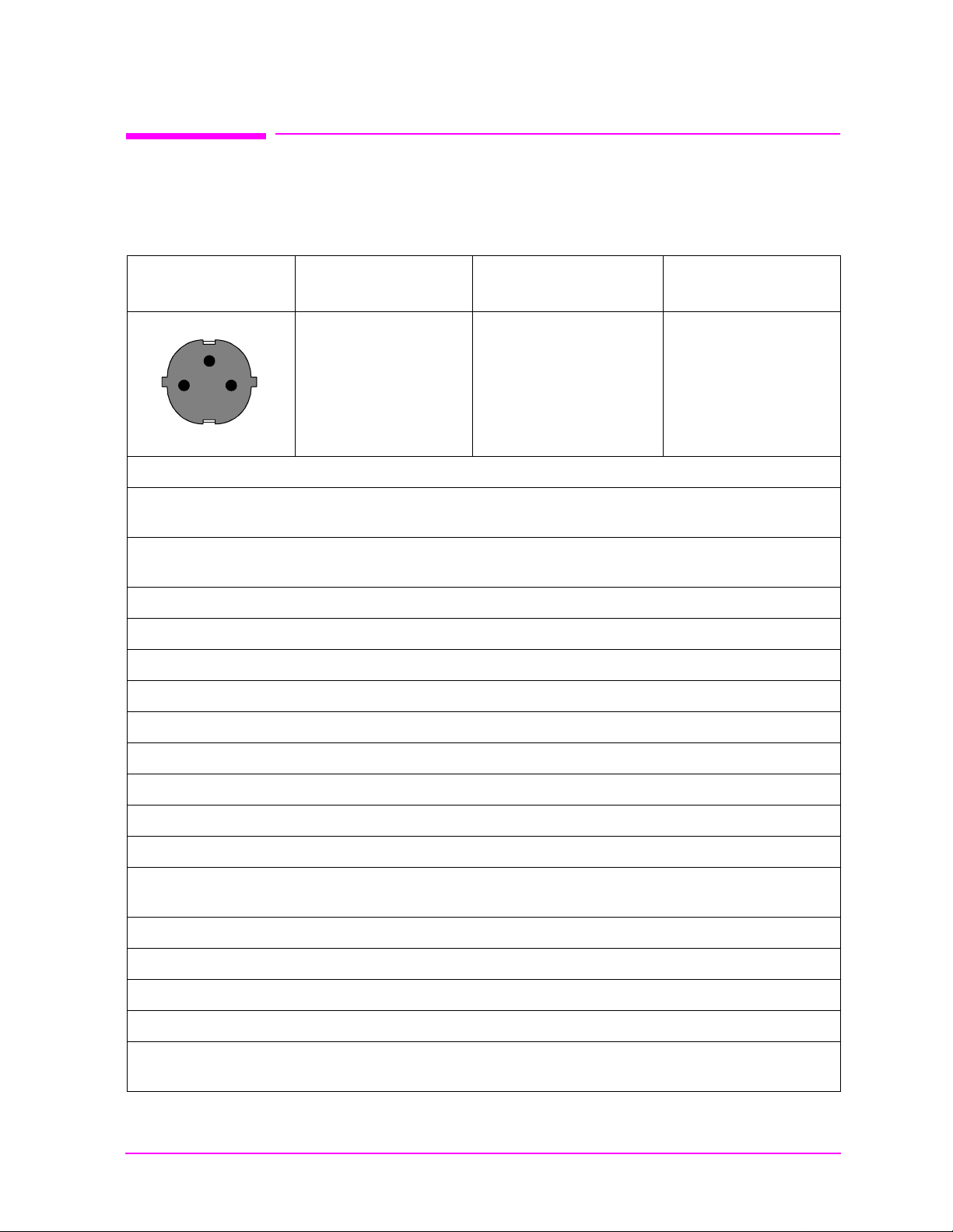
Table 3
Earth
Ground
Line Neutral
Power Cables
Plug type
Plug Descriptions
male/female
Straight/Straight
Straight/90
°
Agilent Part #
(cable & plug)
8120-1689
8120-1692
Cable Descriptions
79 inches, mint gray
79 inches, mint gray
Used in the following locations:
Bangladesh, Belgium, Benin, Bolivia, Boznia-Herzegovina, Bulgaria, Burkina Faso, Burma,
Burundi,Byelarus
Cameroon, Canary Islands, Central African Republic, Chad, Chile, Comoros, Congo, Croatia,
Czech Republic, Czechoslovakia
Denmark, Djibouti
East Germany, Egypt, Estonia, Ethiopia
Finland, France, French Guiana, French Indian Ocean Areas
Gabon, Gaza Strip, Geor gia, Germany, Gozo, Greece
Hungary
Iceland, Indonesia, Iran, Iraq, Israel, Italy, Ivory Coast
Jordan
Kazakhstan, Korea, Kyrgystan
Latvia, Lebanon, Libya, Lithuania, Luxembourg
Macedonia, Madeira Islands, Malagasy Republic, Mali, Malta, Mauritania, Miquelon, Moldova,
Mongolia, Morocco, Mozambique
Nepal, Netherlands, Netherlands Antilles, Niger, Norway
Oman
Pakistan, Paraguay, Poland, Portugal
Rep. South Africa, Romania, Russia, Rwanda
Saudi Arabia (220V), Senegal, Slovak Republic, Slovenia, Somalia, Spain, Spanish Africa, Sri
Lanka, St. Pierce Islands
13
Page 14
Plug type
Earth
Ground
Line Line
Earth
Ground
Line Neutral
Plug Descriptions
male/female
Agilent Part #
(cable & plug)
Sweden, Syria
Tajikistan, Thailand, Togo, Tunisa, Turkey, Turkmenistan
USSR, Ukraine, Uzbekistan
W estern Africa, Western Sahara
Yugoslavia
Zaire
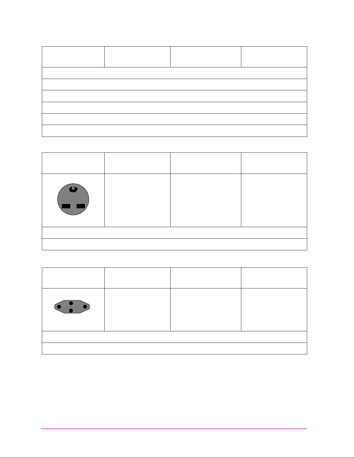
Table 4
Cable Descriptions
Plug Type
Plug Descriptions
male/female
Straight/Straight
Straight/90°
Used in the following locations:
Peru
Table 5
Plug Type
Plug Descriptions
male/female
Straight/Straight
Straight/90°
Agilent Part #
(cable & plug)
Cable Descriptions
8120-0698 90 inches, black
Agilent Part #
(cable & plug)
8120-2104
8120-2296
Cable Descriptions
79 inches, gray
79 inches, gray
Used in the following locations:
Switzerland
14
S:\agilent\e8285\ALR\Book\chapters\front.fm
Page 15

Table 6
125V
Earth
Ground
LineNeutral
Plug Type
Plug Descriptions
male/female
Straight/Straight
Straight/90°
Straight/Straight
Agilent Part #
(cable & plug)
8120-1378
8120-1521
8120-1751
Used in the following locations:
American Samoa
Bahamas, Barbados, Belize, Bermuda, Brazil
Caicos, Cambodia, Canada, Cayman Islands, Columbia, Costa Rica, Cuba
Dominican Republic
Ecuador, El Salvador
French West Indies
Guam, Guatemala, Guyana
Cable Descriptions
90 inches, jade gray
90 inches, jade gray
90 inches, jade gray
Haiti, Honduras
Jamaica
Korea
Laos, Leeward and Windward Islands, Liberia
Mexico, Midway Islands
Nicaragua
Other Pacific Islands
Panama, Philippines, Puerto Rico
Saudi Arabia (115V, 127V), Suriname
Taiwan, Tobago, Trinidad, Trust Territories of Pacific Islands
Turks Island
United States
Venezuela, Vietnam, Virgin Islands of the U.S.
Wa ke Island
15
Page 16

Table 7
JIS C 8303, 100 V
Earth
Ground
LineNeutral
Earth
Ground
Line
Neutral
Plug Type
Plug Descriptions
male/female
Straight/Straight
Straight/90°
Used in the following locations:
Japan
Table 8
Plug Type
Plug Descriptions
male/female
90°/Straight
90°/90°
Straight/Straight
Agilent Part #
(cable & plug)
8120-4753
8120-4754
Agilent Part #
(cable & plug)
8120-2956
8120-2957
8120-3997
Cable Descriptions
90 inches, dark gray
90 inches, dark gray
Cable Descriptions
79 inches, gray
79 inches, gray
79 inches, gray
Used in the following locations:
Denmark
Greenland
16
S:\agilent\e8285\ALR\Book\chapters\front.fm
Page 17

Table 9
Earth
Ground
Line
Neutral
Line
Neutral
Earth
Ground
Plug Type
Plug Descriptions
male/female
Straight/Straight
Straight/90°
Used in the following locations:
Botswana
India
Lesotho
Malawi
South-West Africa (Namibia), Switzerland
Zambia, Zimbabwe
Table 10
Agilent Part #
(cable & plug)
8120-4211
8120-4600
Cable Description
79 inches, mint gray
79 inches, mint gray
Plug Type
Plug Descriptions
male/female
Straight/Straight
Straight/Straight
Straight/90°
Straight/90°
Used in the following locations:
System Cabinets
Agilent Part #
(cable & plug)
8120-1860
8120-1575
8120-2191
8120-4379
Cable Descriptions
60 inches, jade gray
30 inches, jade gray
60 inches, jade gray
15.5 inches, jade gray
17
Page 18

Table 11
Earth
Ground
Line
Neutral
Plug Type (Male)
Plug Descriptions
male/female
90°/Straight
90°/90°
Used in the following locations:
Bahrain, British Indian Ocean Terr., Brunei
Canton, Cyprus
Enderbury Island, Equatorial Guinea
Falkland Islands, French Pacific Islands
Gambia, Ghana, Gibraltar, Guinea
Hong Kong
Ireland
Kenya, Kuwait
Agilent Part #
(cable and plug)
8120-1351
8120-1703
Cable Descriptions
90 inches, mint gray
90 inches, mint gray
Macao, Malaysia, Mauritius
Nigeria
Qatar
Seychelles, Sierra Leone, Singapore, Southern Asia, Southern Pacific Islands, St. Helena, Sudan
Tanzania
Uganda, United Arab Emirates, United Kingdom
Yeman (Aden & Sana)
18
S:\agilent\e8285\ALR\Book\chapters\front.fm
Page 19

Table 12
Line
Neutral
Earth
Ground
Plug Type
Plug Descriptions
male/female
Straight/Straight
Straight/90°
Used in the following locations:
Argentina, Australia
China (People’s Republic)
New Zealand
Papua New Guinea
Urugray
We stern S amoa
Agilent Part #
(cable & plug)
8120-1369
8120-0696
Cable Descriptions
79 inches, gray
80 inches, gray
19
Page 20

ATTENTION
Static Sensitive
Devices
This instrument was constructed in an ESD (electro-static discharge) protected environment. This is
because most of the semi conductor devices used in this instrument are susceptible to damage by
static discharge.
Depending on the magnitude of the charge, device substrates can be punctured or destroyed by
contact or mer e pr oxim ity of a stat ic char ge. Th e r esult can cause degra dation of d evice performance,
early failure, or immediate destruction.
These charges are generated in numerous ways such as simple contact, separation of materials, and
normal motions of persons working with static sen sitive devices.
When handling or s ervicin g equi pment co ntaini ng st atic sensit ive devi ces, ad equate p r eca ution s mus t
be taken to prevent device damage or destruction.
Only those who are thoroughly familiar with industry accepted techniques for handling static
sensitive devices should attempt to service circuitry with these devices.
In all instances, measures must be taken to prevent static charge build-up on work surfaces and
persons handling the devices.
20
S:\agilent\e8285\ALR\Book\chapters\front.fm
Page 21

Contents
1. Introduction
Test Set Description . . . . . . . . . . . . . . . . . . . . . . . . . . . . . . . . . . . . . . . 26
Product Description. . . . . . . . . . . . . . . . . . . . . . . . . . . . . . . . . . . . . . . . 28
Troubleshooting Strategy . . . . . . . . . . . . . . . . . . . . . . . . . . . . . . . . . . . 36
Repair Process . . . . . . . . . . . . . . . . . . . . . . . . . . . . . . . . . . . . . . . . . . . . 37
Calibration and Performance Verification . . . . . . . . . . . . . . . . . . . . . . 38
System Power Calibration Program . . . . . . . . . . . . . . . . . . . . . . . . . . . 39
Test Equipment Needed for the System Power Calibration Program 40
E8285A Support Contacts. . . . . . . . . . . . . . . . . . . . . . . . . . . . . . . . . . . 41
Hardware and Firmware Enhancements . . . . . . . . . . . . . . . . . . . . . . 42
Ordering New Manuals . . . . . . . . . . . . . . . . . . . . . . . . . . . . . . . . . . . . . 43
2. Troubleshooting
How to Troubleshoot the Test Set . . . . . . . . . . . . . . . . . . . . . . . . . . . . 46
Self-Test Diagnostics . . . . . . . . . . . . . . . . . . . . . . . . . . . . . . . . . . . . . . . 48
Functional Diagnostics . . . . . . . . . . . . . . . . . . . . . . . . . . . . . . . . . . . . . 58
AF, RF, and CDMA Diagnostics . . . . . . . . . . . . . . . . . . . . . . . . . . . . . . 64
Frequently Encountered Diagnostic Messages . . . . . . . . . . . . . . . . . . 68
Manual Troubleshooting Procedures . . . . . . . . . . . . . . . . . . . . . . . . . . 70
Service Screen . . . . . . . . . . . . . . . . . . . . . . . . . . . . . . . . . . . . . . . . . . . . 79
3. Disassembly and Replaceable Parts
Before You Start. . . . . . . . . . . . . . . . . . . . . . . . . . . . . . . . . . . . . . . . . . . 84
Disassembly Procedures . . . . . . . . . . . . . . . . . . . . . . . . . . . . . . . . . . . . 87
Parts List . . . . . . . . . . . . . . . . . . . . . . . . . . . . . . . . . . . . . . . . . . . . . . . 105
4. Functional Verification
5. Periodic Adjustments/Calibration
Periodic Adjustments. . . . . . . . . . . . . . . . . . . . . . . . . . . . . . . . . . . . . . 126
Storing Calibration Factors. . . . . . . . . . . . . . . . . . . . . . . . . . . . . . . . . 129
Running the Periodic IQ, or IQ Demod Path Calibration Programs. 130
Periodic Calibration Menu Descriptions. . . . . . . . . . . . . . . . . . . . . . . 131
Setting the Timebase Latches . . . . . . . . . . . . . . . . . . . . . . . . . . . . . . 135
IQ Calibration Program Description . . . . . . . . . . . . . . . . . . . . . . . . . 137
IQ Demod Path Calibration Program Description. . . . . . . . . . . . . . . 139
6. Performance Tests
Procedure and Equipment. . . . . . . . . . . . . . . . . . . . . . . . . . . . . . . . . . 142
RF Generator FM Distortion
Performance Test 1 . . . . . . . . . . . . . . . . . . . . . . . . . . . . . . . . . . . . . . . 146
RF Generator FM Accuracy
Performance Test 2 . . . . . . . . . . . . . . . . . . . . . . . . . . . . . . . . . . . . . . . 149
RF Generator FM Flatness
Performance Test 3 . . . . . . . . . . . . . . . . . . . . . . . . . . . . . . . . . . . . . . . 152
RF Generator Residual FM
Performance Test 4 . . . . . . . . . . . . . . . . . . . . . . . . . . . . . . . . . . . . . . . 155
RF Generator Level Accuracy
21
Page 22

Contents
Performance Test 5 . . . . . . . . . . . . . . . . . . . . . . . . . . . . . . . . . . . . . . . 158
RF Generator Harmonics Spectral Purity
Performance Test 6 . . . . . . . . . . . . . . . . . . . . . . . . . . . . . . . . . . . . . . . 163
RF Generator Spurious Spectral Purity
Performance Test 7 . . . . . . . . . . . . . . . . . . . . . . . . . . . . . . . . . . . . . . . 165
AF Generator AC Level Accuracy
Performance Test 8 . . . . . . . . . . . . . . . . . . . . . . . . . . . . . . . . . . . . . . . 167
AF Generator DC Level Accuracy
Performance Test 9 . . . . . . . . . . . . . . . . . . . . . . . . . . . . . . . . . . . . . . . 168
AF Generator Residual Distortion
Performance Test 10 . . . . . . . . . . . . . . . . . . . . . . . . . . . . . . . . . . . . . . 169
AF Generator Frequency Accuracy
Performance Test 11 . . . . . . . . . . . . . . . . . . . . . . . . . . . . . . . . . . . . . . 170
AF Analyzer AC Level Accuracy
Performance Test 12 . . . . . . . . . . . . . . . . . . . . . . . . . . . . . . . . . . . . . . 171
AF Analyzer Residual Noise
Performance Test 13 . . . . . . . . . . . . . . . . . . . . . . . . . . . . . . . . . . . . . . 172
AF Analyzer Distortion and SINAD Accuracy
Performance Test 14 . . . . . . . . . . . . . . . . . . . . . . . . . . . . . . . . . . . . . . 173
AF Analyzer DC Level Accuracy
Performance Test 15 . . . . . . . . . . . . . . . . . . . . . . . . . . . . . . . . . . . . . . 174
AF Analyzer Frequency Accuracy to 100 kHz
Performance Test 16 . . . . . . . . . . . . . . . . . . . . . . . . . . . . . . . . . . . . . . 175
AF Analyzer Frequency Accuracy at 400 kHz
Performance Test 17 . . . . . . . . . . . . . . . . . . . . . . . . . . . . . . . . . . . . . . 176
Oscilloscope Amplitude Accuracy
Performance Test 18 . . . . . . . . . . . . . . . . . . . . . . . . . . . . . . . . . . . . . . 177
RF Analyzer Level Accuracy
Performance Test 19 . . . . . . . . . . . . . . . . . . . . . . . . . . . . . . . . . . . . . . 179
RF Analyzer FM Accuracy
Performance Test 20 . . . . . . . . . . . . . . . . . . . . . . . . . . . . . . . . . . . . . . 180
RF Analyzer FM Distortion
Performance Test 21 . . . . . . . . . . . . . . . . . . . . . . . . . . . . . . . . . . . . . . 182
RF Analyzer FM Bandwidth
Performance Test 22 . . . . . . . . . . . . . . . . . . . . . . . . . . . . . . . . . . . . . . 184
RF Analyzer Residual FM
Performance Test 23 . . . . . . . . . . . . . . . . . . . . . . . . . . . . . . . . . . . . . . 186
Spectrum Analyzer Image Rejection
Performance Test 24 . . . . . . . . . . . . . . . . . . . . . . . . . . . . . . . . . . . . . . 188
CDMA Generator RF IN/OUT Amplitude Level Accuracy
Performance Test 25 . . . . . . . . . . . . . . . . . . . . . . . . . . . . . . . . . . . . . . 190
CDMA Generator DUPLEX OUT Amplitude Level Accuracy
Performance Test 26 . . . . . . . . . . . . . . . . . . . . . . . . . . . . . . . . . . . . . . 192
CDMA Generator Modulation Accuracy
Performance Test 27 . . . . . . . . . . . . . . . . . . . . . . . . . . . . . . . . . . . . . . 194
CDMA Analyzer Average Power Level Accuracy
Performance Test 28 . . . . . . . . . . . . . . . . . . . . . . . . . . . . . . . . . . . . . . 196
CDMA Analyzer Channel Power Level Accuracy
Performance Test 29 . . . . . . . . . . . . . . . . . . . . . . . . . . . . . . . . . . . . . . 198
22
Page 23

Contents
7. Performance Test Records
RF Generator FM Distortion
Performance Test 1 Record . . . . . . . . . . . . . . . . . . . . . . . . . . . . . . . . . 202
RF Generator FM Accuracy
Performance Test 2 Record . . . . . . . . . . . . . . . . . . . . . . . . . . . . . . . . . 204
RF Generator FM Flatness
Performance Test 3 Record . . . . . . . . . . . . . . . . . . . . . . . . . . . . . . . . . 206
RF Generator Residual FM
Performance Test 4 Record . . . . . . . . . . . . . . . . . . . . . . . . . . . . . . . . . 208
RF Generator Level Accuracy
Performance Test 5 Record . . . . . . . . . . . . . . . . . . . . . . . . . . . . . . . . . 210
RF Generator Harmonics Spectral Purity
Performance Test 6 Record . . . . . . . . . . . . . . . . . . . . . . . . . . . . . . . . . 218
RF Generator Spurious Spectral Purity
Performance Test 7 Record . . . . . . . . . . . . . . . . . . . . . . . . . . . . . . . . . 221
AF Generator AC Level Accuracy
Performance Test 8 Record . . . . . . . . . . . . . . . . . . . . . . . . . . . . . . . . . 223
AF Generator DC Level Accuracy
Performance Test 9 Record . . . . . . . . . . . . . . . . . . . . . . . . . . . . . . . . . 225
AF Generator Residual Distortion
Performance Test 10 Record . . . . . . . . . . . . . . . . . . . . . . . . . . . . . . . . 226
AF Generator Frequency Accuracy
Performance Test 11 Record . . . . . . . . . . . . . . . . . . . . . . . . . . . . . . . . 228
AF Analyzer AC Level Accuracy
Performance Test 12 Record . . . . . . . . . . . . . . . . . . . . . . . . . . . . . . . . 229
AF Analyzer Residual Noise
Performance Test 13 Record . . . . . . . . . . . . . . . . . . . . . . . . . . . . . . . . 230
AF Analyzer Distortion and SINAD Accuracy
Performance Test 14 Record . . . . . . . . . . . . . . . . . . . . . . . . . . . . . . . . 231
AF Analyzer DC Level Accuracy
Performance Test 15 Record . . . . . . . . . . . . . . . . . . . . . . . . . . . . . . . . 232
AF Analyzer Frequency Accuracy to 100 kHz
Performance Test 16 Record . . . . . . . . . . . . . . . . . . . . . . . . . . . . . . . . 233
AF Analyzer Frequency Accuracy at 400 kHz
Performance Test 17 Record . . . . . . . . . . . . . . . . . . . . . . . . . . . . . . . . 234
Oscilloscope Amplitude Accuracy
Performance Test 18 Record . . . . . . . . . . . . . . . . . . . . . . . . . . . . . . . . 235
RF Analyzer Level Accuracy
Performance Test 19 Record . . . . . . . . . . . . . . . . . . . . . . . . . . . . . . . . 236
RF Analyzer FM Accuracy
Performance Test 20 Record . . . . . . . . . . . . . . . . . . . . . . . . . . . . . . . . 238
RF Analyzer FM Distortion
Performance Test 21 Record . . . . . . . . . . . . . . . . . . . . . . . . . . . . . . . . 239
RF Analyzer FM Bandwidth
Performance Test 22 Record . . . . . . . . . . . . . . . . . . . . . . . . . . . . . . . . 240
RF Analyzer Residual FM
Performance Test 23 Record . . . . . . . . . . . . . . . . . . . . . . . . . . . . . . . . 241
Spectrum Analyzer Image Rejection
Performance Test 24 Record . . . . . . . . . . . . . . . . . . . . . . . . . . . . . . . . 242
23
Page 24

Contents
CDMA Generator RF IN/OUT Amplitude Level Accuracy
Performance Test 25 Record . . . . . . . . . . . . . . . . . . . . . . . . . . . . . . . . 243
CDMA Generator DUPLEX OUT Amplitude Level Accuracy
Performance Test 26 . . . . . . . . . . . . . . . . . . . . . . . . . . . . . . . . . . . . . . 244
CDMA Generator Modulation Accuracy
Performance Test 27 Record . . . . . . . . . . . . . . . . . . . . . . . . . . . . . . . . 245
CDMA Analyzer Average Power Level Accuracy
Performance Test 28 Record . . . . . . . . . . . . . . . . . . . . . . . . . . . . . . . . 246
CDMA Analyzer Channel Power Level Accuracy
Performance Test 29 Record . . . . . . . . . . . . . . . . . . . . . . . . . . . . . . . . 247
8. Block Diagrams
Signal Flow and Interconnections . . . . . . . . . . . . . . . . . . . . . . . . . . . 250
RF Input/Output Section. . . . . . . . . . . . . . . . . . . . . . . . . . . . . . . . . . . 253
RF Analyzer Section . . . . . . . . . . . . . . . . . . . . . . . . . . . . . . . . . . . . . . 255
Spectrum Analyzer . . . . . . . . . . . . . . . . . . . . . . . . . . . . . . . . . . . . . . . 264
Audio Analyzer Section . . . . . . . . . . . . . . . . . . . . . . . . . . . . . . . . . . . 266
CDMA Analyzer Section . . . . . . . . . . . . . . . . . . . . . . . . . . . . . . . . . . . 271
CDMA Generator Section . . . . . . . . . . . . . . . . . . . . . . . . . . . . . . . . . . 275
Audio Generator Section . . . . . . . . . . . . . . . . . . . . . . . . . . . . . . . . . . 277
RF Generator Section . . . . . . . . . . . . . . . . . . . . . . . . . . . . . . . . . . . . . 279
Reference/Regulator Section . . . . . . . . . . . . . . . . . . . . . . . . . . . . . . . 284
Instrument Control Section. . . . . . . . . . . . . . . . . . . . . . . . . . . . . . . . . 287
GPIB Serial . . . . . . . . . . . . . . . . . . . . . . . . . . . . . . . . . . . . . . . . . . . . . 291
9. Service Screen
Troubleshooting with the SERVICE Screen . . . . . . . . . . . . . . . . . . . 294
24
Page 25

1 Introduction
This manual explains how to repair and calibrate the Agilent
Technologies E8285A CDMA/PCS Mobile Station Test Set; called the
“Test Set” throughout this manual.
Throughout this manual you will see this note:
NOTE Test Sets with firmware revision A.04.5X and above operate only at RF
frequencies from 800 to 1000 MHz and 1700 to 2000 MHz. A text only error
message
frequencies are set.
The purpose of this note is to bring attention to RF frequency band
coverage provided by firmware revisi on A.04.5X and above. Test Sets
with firmware revision A.02.XX and below can operate at RF
frequencies from 100 (usable to 30 MHz) to 1000 and 1700 to 2000 MHz.
“Input value out of range”, will be displayed if invalid
25
Page 26
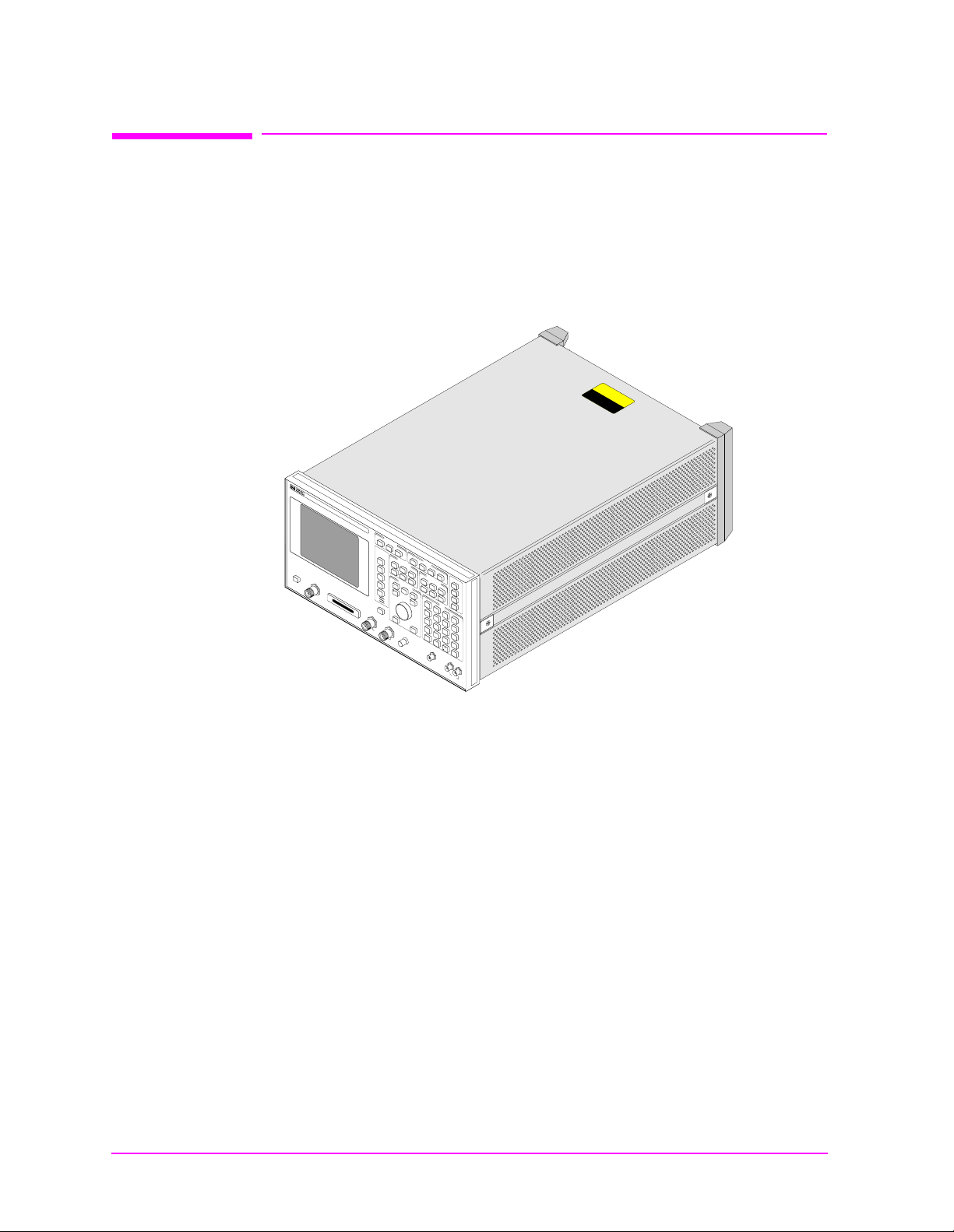
Introduction
Test Set Description
Test Set Description
Several analog and digital test instruments are integrated into the
E8285A CDMA Mobile Station Test Set to test Code Division Multiple
Access (CDMA) digital cellular, PCS, and s everal types of analog mobile
phones, such as AMPS, NAMPS, and TACS.
Figure 1-1 The E8285A CDMA Mobile Station Test Set
N
O
I
T
U
A
C
TWO PERSON LIFT
8285iso.eps
Answer
C
A
L
Call/
L
Call/
C
Pa
O
ge
N
Page
T
R
O
L
End/
En
Relea
d/
Re
se
lease
U
S
R
E
egister
R
Re
gister
K
1
'
Print Printer
K
Tests
1
C
K
Cell config
D
Tests
1
M
U
A
T
Ca
S
I
L
ll
C
Call
I
R
T
control
K
2
'
K
2
K
POW
ER
RF IN/OU
D
O
N
T
w
O
h
T
e
a
n
p
in
p
ly
s
R
t
a
n
F
d
b
y
M
a
x
p
o
w
e
r
2
.
5
W
2
K
3
'
K
3
K
3
A
s
s
ig
K
4
K
4
R
e
le
K
5
K
5
Shift
S
hift
D
U
PL
EX O
UT
M
a
x
p
o
w
e
r
I
E
E
Config
con
E
S
Spectrum
N
C
trol
on
S
fig
M
G
I/O
S report MS F
en
G
con
en
co
R
fig
ntrol
X
control
Previous
SM
R
test
X test
Pr
S
eviou
Authen-
Help
s
Authen-
ER
tication
TX test
tication
Me
T
X test
ssage
Message
A
N
A
L
O
TX
G
C
all
T
S
C
X
range
C
all
Ref
co
n
a
s
e
AN
TENN
6
0
m
W
R
range
D
ntro
control
set
E
A
E
l
T
Increm
N
A
F
Increm
10
U
en
N
t
10
M
ent
eter
Low limit
Increm
Increment
set
set
IBA
SIC
reset
Can
C
cel
an
cel
A IN
VO
LU
C
T
ent
M
IO
N
Increme
x 1
E
S
A
verage
Increment
x 10
nt
0
High lim
RX
test
RX test
it
789
4
1
0.
Y
e
O
7
4
1
0
Y
es
O
s
n/O
AU
D
up
TX
n/O
ff
ff
DIO
M
a
x
Duplex
lex
TX
test
test
56
2
No
R
atio
W
O
1
2
V
p
Preset
S
Preset
Hold
Spe
Meas
Sp
ctrun
analyzer
ectrun
Mea
reset
ana
s
re
lyz
set
er
Address
AF
Local
AF
analyzer
Lo
a
cal
nalyzer
Sav
e
Recall
Recall
D
A
T
A
8
9
5
E
nter
E
nter
6
2
G
hz
G
d
hz
Bm
dB
d
B
m
3
d
B
3
.
M
H
M
z
V
H
z
V
%
+
%
/-
+
/
-
N
o
Ra
k
tio
Hz
W
kH
m
z
V
mV
s
%
s
%
d
B
d
B
m
W
H
z
Hz
UT
µ
V
µV
m
s
m
s
H
igh
AUD
IO IN
e
a
k
Low
M
a
x
4
2
V
p
e
a
k
Some of the instrument functions in the Test Set include:
• Synthesized AM, FM, and IQ modulation signal generator
• AM, FM and IQ modulation analyzer
• Duplex offset signal generator
• SSB demodulator
• RF power meter
• Audio and RF frequency counter and RF frequency error meter
• AC and DC voltmeter
• Distortion, SINAD, and signal-to-noise-ratio meters
• Two variable audio sources
• Oscilloscope
• Spectrum analyzer and tracking generator (optional)
• Signaling encoder and decoder
• DC current meter
26 S:\agilent\e8285\ALR\Book\chapters\intro.fm
Page 27

Introduction
Test Set Description
Some of these functions are dire ctly replaceable as semblies (such as the
spectrum analyzer); some functions are digitally derived from other
assemblies (such as the oscilloscope). Most of the replaceable
assemblies are plug-in components.
Most instrument functions can be cont rolled by front-panel (local)
controls and by remote commands ( using a c onnected controll er). Power
on/off, volume, and squelch controls cannot be accessed remotely.
Controls are grouped together on display screens that are usually
associated with a specific task (suc h as making a call to a CDMA mobile
phone).
An Instrument BASIC (IB ASIC) control ler is also built into the T es t Set
to allow automated operation without using an external controller. This
computer also has the ability to be a system controller to other tes t
system instruments. Refer to the Test Set’s user’s guide for information
on using the IBASIC computer (also referred to as the IBASIC
controller).
27
Page 28

Introduction
Product Description
Product Description
The E8285A CDMA Mobile Test Set is designed to meet the needs of
Cellular Provider Point of Sale Retailers, manufacturing customers,
and other customers who require CDMA Mobile Phone test capability.
The Tes t Set is very similar to it’s predecessor, the Agilent Technologies
8924C with the addition of newly designed RF I/O module, upconverter
and downconverter assemblies. These assemblies extend the Test Set
frequency range to cover the 1800- 1900 MHz PCS Cellular band as well
as providing standard 800 MHz cellular band coverage.
Internal Ope rating System
A Motorola® 68020 − 33 MHz microprocessor acts as the ho st pro cesso r
of the Test Set. It receives commands from the front-panel co ntrols and
communicates directly with almost every assembly inside the Test Set.
The host is also in constant communication with several other
microprocessors located throughout the Test Set.
Communications to the GPIB , s erial, a nd paralle l ports are t hrough the
control int e rface assembly to th e ho st processor.
This processor is also the core for the internal IBASIC computer. The
IBASIC computer is used t o load and run var ious sof tw are pac kages f or
automated radio tests. It is also responsible for executing the internal
diagnostic routines used to troubleshoot a failing inst rument.
Instrument Frequency References
The Test Set reference ti mebase path co n s i st s o f tw o assemblies, an
ovenized high stability reference assembly and a CDMA reference
assembly. These two assemblies provide all frequency, phase, and
timing signals used to accurately synthesize all of the Test Set’s source
and analysis signals. A master reference signal can originate from
either an external source at the 10 MHz input on the rear panel, or
from the internal 10 MHz phase locked loop oscillator located on the
high stability reference asse mbly. The high stability refere nce assembly
provides timebase references for the analog assemblies and a 10 MHz
reference signal to the CDMA reference assembly. The CDMA reference
assembly uses this signal to generate clock and timing signals for
internal CDMA assemblies, provide the 10 MHz output signal to the
rear panel, and generate the AWGN (Additive White Gaussian Noise) I
& Q noise source signals.
28 S:\agilent\e8285\ALR\Book\chapters\intro.fm
Page 29

Figure 1-2 Reference Signal Generation
Introduction
Product Description
Rear Panel External
Reference In
1, 2, 5, 10 MHz
Rear Panel External
Reference Out
10 MHz
OC XO H igh Stability
Reference Assembly
10 MHz In
CDMA Reference
Assembly
AWGN
To internal analo g assemblies.
See block diagrams for mor e
information.
To internal digital assemblies.
See block diagrams for more
information.
To I/Q Modulator Assembly
29
Page 30
Introduction
Product Description
RF Analysis
RF signals connected to the front panel RF IN/OUT connector or
ANTENNA IN connector go to the RF I/O module. The signal level and
RF frequency are measured, and the level is adjusted using fixed step
and variable attenuators in the separate downconverter module.
CAUTION Over-Power Damage
The ANTENNA IN connector is only used for very low level signals
(60 mW or less), and cannot be used for Transmitter (TX) Power
measurements. Exceeding this limit may destroy the RF I/O module.
The RF IN/OUT connector is used to m easure direc t mobile transm itter
power up to 2.5 Watts continuous.
The downconverter mixes the input signal with a local oscillator signal
from the Receiver Synthesizer ass embly to produc e a 114.3 MHz, 6 14.3,
or 385.7 MHz IF signal (depending on the frequency of the received
signal). The signal goes through a bandpass filter and then on to the
Receiver assembly.
If the IF is 614.3 or 385.7 MHz, the Receiver assembly mixes the signal
with a 500 MHz local oscillator (LO) signal from the Reference
assembly to obtain the 114.3 MHz IF. If the IF is 114.3 MHz, the signal
bypasses this downconversion. The 114.3 MHz si gnal divides into two
paths.
Figure 1-3 Received Signal Downconversion
Downconverter
1200-1700 MHz from
Receiver Synthesizer
Assembly
385.7 MHz
RF I/O
RF IN/OUT
114.3 MHz
614.3 MHz
ANTENNA
IN
Power
Detector
486-1026 MHz from
Receiver Synthesizer
Assembly
Receiver Assembly
114.3 MHz
500 MHz from
Reference Assy
To LO/IF Demod Assembly
114.3 MHz
AM, FM, SSB
Demodulation
30 S:\agilent\e8285\ALR\Book\chapters\intro.fm
Page 31

AM, FM, or SSB Modulation Analysis
For AM, FM, or SSB signals, t h e 114.3 MHz signal is downconverted to
10.7 MHz and routed through a user-selected IF bandpass filter
(15 kHz or 230 kHz) that is centered around the 10.7 MHz IF. AM and
SSB signals are demodulated at this point; FM signals are
downconverted to a 700 kHz IF before demodulation. The demodulated
signal is routed to the Audio Analyzer 1 assembly for audio frequency
filtering. This assembly is also connected to the front-panel AUDIO IN
connector for direct audio measur eme n ts. Several low pass and high
pass filters can be selected, as well as a C-Message or optional CCITT
bandpass filter. Frequency and voltage measurements are then made
on this signal by the Measurement assembly. The signal is then routed
to the Audio Analyzer 2 assembly.
The Audio Analyzer 2 assembly routes the signal through a
user-selectable detector. A variable frequency notch filter may also be
selected for SINAD and distortion measurements. The detector’s si g n al
is then sent to several other assemblies:
Introduction
Product Description
• The Measurement assembly measures and displays the modulation
level (such as FM deviation) and provide the input to the
oscilloscope.
• The Signaling Source Analyzer assembly for signaling decoding.
• The rear-panel AUD MONITOR OUTPUT connector for e xternal use
of the demodulated signal.
• The front-panel VOLUME control and internal speaker to listen to
the demodulat e d sign a l .
Figure 1-4 AM, FM, and SSB Signal Demodulation and Filtering
Receiver Assembly
114.3 MHz
IF
10.7 MHz
125 MHz
Audio Analyzer 2 Assembly
Selectable Detectors
RMS
RMS*SQRT2
Pk+
Pk-
.......
15 kHz
230 kHz
IF Filters
(centered around 10.7 MHz)
Variable Freq.
Notch Filter
10 MHz from
Reference Assembly
RMS
Detector
AM Demod
SSB Demod
FM Demod
Signaling Source Analyzer
AUD MONITOR OUTPUT (Rear panel)
Measurement Assembly
Audio Analyzer 1 Assembly
AUDIO IN
(front pane l)
VOLUME
Selectable
High-Pass
Filters
Selectable
Low-Pass
Filters
DC Volts and
Audio Frequency
Measurements
31
Page 32

Introduction
Product Description
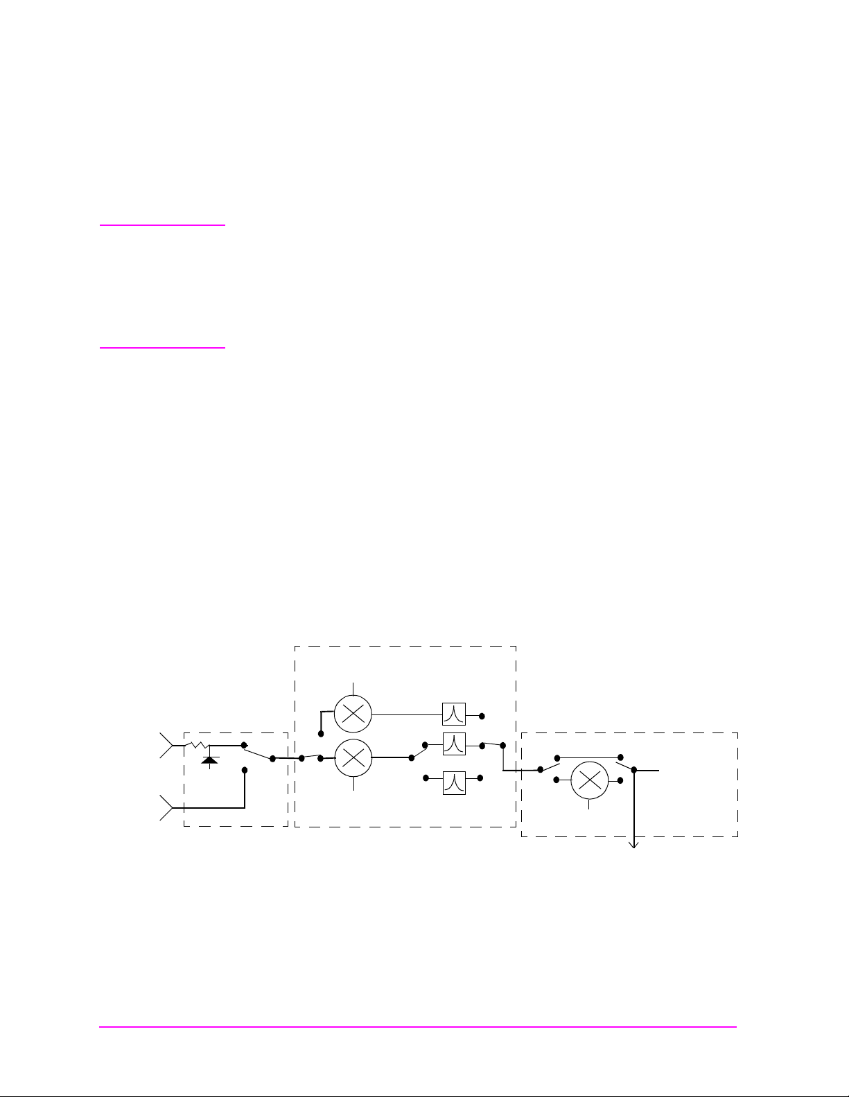
CDMA Signal Analysis
The 114.3 MHz IF also goes to the CDMA LO/IF Demodulation
assembly. This assembly provides a through path to the spec trum
analyzer (Option 102) for all RF signals, and also provides down
conversion for CDMA signals, measurements and call proce ss ing.
To do wnconvert the CDMA signal, the 114.3 MHz IF is mixed with a
117.9864 MHz local oscillator (LO) signal to produce a 3.6864 MHz IF.
(The LO signal is from an oscillator that is phase locked to a 10 MHz
signal from the CDMA Reference module.)
The 3.6864 MHz signal is split and goes to the Receiver DSP assembly,
and also through a variable-gain IF amplifier before IQ demodulation.
The demodulated I and Q baseband signals are then routed to the
Digital Cellsite assemblies.
Under control from the Pr otocol Processor as sembly, the Digital Cellsit e
assemblies use the demodulated IQ inform ation to s et up and mai ntain
calls to CDMA phones. The Digital Cellsite 1 assembly also supplies
feedback to the C D M A L O / I F Demodulation assembly to con t rol the
level of the variable-gain IF amplifier into the demodulator.
The Receive DSP assembly converts, digitizes, and provides final
analysis on the 3.6864 MHz signal to make measurements, such as rho,
timing accuracy, carrier feedthrough, and phase error.
Figure 1-5 Analyzing CDMA Signals
114.3MHz IF
from Receiver
CDMA LO/IF Demodulation Assembly
3.6864 MHz
117.9864 MHz
Demodulator
IQ
IF Gain Control
I data
Q data
T o Spectrum Analyzer
Digital Cellsite
1 & 2 Assemblies
IQ Decoding and
CDMA Generator
Data Coding
Receive DSP Assembly
CDMA IQ Modulation
Measurements
Protocol
Processor
Call Setup and
Control
32 S:\agilent\e8285\ALR\Book\chapters\intro.fm
Page 33

RF Signal Generation
The Signal Generator Synthesizer assembly creates a 500 to 1000 MHz
signal. The reference signal for the synthesizer is supplied by the High
Stability Reference assembly. The synthesizer’s fr equency is varied
using a divider network i n t he feed back ci rcuit of the ph ase loc ked lo op .
Any FM modulation signal (from the Modulation Distributi on
assembly), and the frequency sweep signal for the spectrum analyzer
and tracking generator, are integrated into this feedback loop. If a
CDMA signal is not being generated, the 500-1000 MHz signal is
passed through the I/Q Modulator assembly, bypassing the I/Q
modulator.
IQ Modulation
If a CDMA signal is being generated, the signal is I/Q modulated in the
I/Q Modulator assembly, using data from the Analog Cellsite assembly.
The Analog Cellsite assembly gets its dat a from the two Digital Cellsite
assemblies, which are controlled by the Protocol Pro cessor assembly. Up
to eight code channels of CDMA modulation data and noise may be
summed into the IQ modulator at one time. These channels provide
phone paging, synchronization, voice (traffic) transmission, and other
CDMA system functions.
Introduction
Product Description
Final Frequency Conversion and Leveling
NOTE Test Sets with firmware revision A.04.5X and above operate only at RF
frequencies from 800 to 1000 MHz and 1700 to 2000 MHz. A text only error
message
frequencies are set.
The RF Output assembly performs three tasks:
• Mixes or divides the 500 to 1000 MHz signal to produce signals
• Provides AM modulation (when selected).
• Controls the signal level out of the assembly using an Automatic
The signal from the RF Output assembly is sent to one of two paths in
the Upconverter assembly. RF frequencies from 30 MHz to 1 GHz route
through the bypass path. PCS frequencies are upconverted to supply
frequencies from 1700 to 2000 MHz. The user-selected frequency
contains desired modulation (AM, FM, or CDMA), or a continuou s wa ve
(CW) signal. The level has been adjusted to provide the required level
(after going through RF I/O assembly).
“Input value out of range”, will be displayed if invalid
below 500 MHz (down to 30 MHz). A 1 GHz LO from the Reference
assembly is used for mixing.
Level Control (ALC) loop.
33
Page 34

Introduction
Product Description
RF and Duplex Outputs
NOTE Test Sets with firmware revision A.04.5X and above operate only at RF
frequencies from 800 to 1000 MHz and 1700 to 2000 MHz. A text only error
message
frequencies are set.
The RF I/O assembly receives the signal from the Upconverter
assembly and routes it to the selected output connector: RF IN/OUT or
DUPLEX OUT. The signal first goes to a variable attenuator for level
control.
If the DUPLEX OUT connector is selected, the signal the n goes direct ly
to that connector without additional attenuation. If the RF IN/OUT
connector is used as an output, the signal passes through additional
attenuation before reaching the connec tor. This is why a greater signal
level can be output through the DUPLEX OUT connector than through
the RF IN/OUT connector.
“Input value out of range”, will be displayed if invalid
34 S:\agilent\e8285\ALR\Book\chapters\intro.fm
Page 35

Figure 1-6 RF Generation Path Overview
Introduction
Product Description
1 MHz from
Reference
Assembly
FM Mod. from
Mod. Dist.
Spec. Analyzer
Sweep
500-1000 MHz
Output Assembly
Signal Generator Synthesizer
500-1000 MHz
div/n
Cell Site
Protocol
Processor
500-1000 MHz
div/2
1 GHz from Reference Assembly
(main band)
250-500 MHz
(÷2 band)
250 kHz-250 MHz
(downconverted band)
Digital 1
Cell Site
Digital 2
RF Amplitude
Adjust fro m
Host Controller
IQ Modulator Assembly
I/Q Modulator
4 channels of
I&Q data
1 channel of
I&Q data
Amplitude
Modulator
Automatic
Level Control
Distribution Assembly.
&
ADC
Summing
RF
Amp
AM from Mod.
Analog Cell Site
AWGN (Noise) from
CDMA Reference
Upconverter Assembly
RF I/O Assembly
Variable Step
Attenuator
To the Receiver
Assembly
DUPLEX
OUT
RF IN/OUT
35
Page 36

Introduction
Troubleshooting Strategy
Troubleshooting Strategy
You can repair the Test Set yourself or s end it to your local Agilent
Technologies Instrument Support Center. Before starting a repair, you
should become familiar with basic Test Set operation using the user’s
guide.
Troubleshooting relies on built-in diagnostics. Because some diagnostic
results may be ambiguous, further interpr etation and testing may be
required. There are several diagnostic routines built into the Test Set:
• Power-up self -test diagnostics to test controller functioning. These
are automatically run when the instrument is turned on, and can
also be run after the instrument has been on.
• RF (Radio Frequency) assembly diagnostics.
• AF (Audio Frequency) assembly diagnostics.
• Digital assembly diagnostics for CDMA signals.
Troubleshooting hints in this manual include:
• Instructions on how to begin troubleshooting (see chapter 2,
"Troubleshooting").
• Block diagrams and theory of operation (this chapter and chapter 8,
"Block Diagrams").
• Detailed information about the built-in diagnostics (see chapter 2,
"Troubleshooting").
• Error message explanations (see chapter 10, "Error Messages").
36 S:\agilent\e8285\ALR\Book\chapters\intro.fm
Page 37

Repair Process
Repairing the Test Set consists of:
• Identifying the faulty ass e mb l y – see chapt er 2, "Troubl eshooting"
• Ordering a replacement assembly – see chapter 3, "Disassembly and
Replaceable Parts"
• Replacing the faulty assembly – see chapter 3, "Disassembly and
Replaceable Parts"
• Downloading calibration data – see chapter 2, "Troubleshooting" and
regenerating calibration data – see See “System Power Calibration
Program” on page 39.
• Performing periodic calibration – see chapter 5, "Periodic
Adjustments/Calibration"
• Fu n ctional Verification – see chapter 4 , "Functional Verification"
Introduction
Repair Process
37
Page 38

Introduction
Calibration and Performance Verification
Calibration and Performance Verification
The Tes t Set periodically requires some maintenance to verify that it
meets its published specifications. See “Periodic Adjustments” on page
126. Periodic Adjust men ts (calibration) consists of running several
built-in calibration programs. The recommended interval for periodic
adjustments is 12 months. An external frequency counter and dc
voltmeter are required. See Chapter 5, "Periodic
Adjustments/Calibration" on page 5.
NOTE The recommended Test Set calibration interval is 24 months. This is
accomplished by performing the performance tests (see Chapter 6,
“Performanc e Tests,” on page 141) or sending the Test Set to an Agilent
Calibration Center or other qualified calibration lab.
The performance tests verif y t h at the Te st Set performs as indicated in
the Specifications. These tests should be performed if the Test Set’s
operation is suspect, even though it passes all internal diagnostic
checks. This ident i fies whether a problem actually exists in the Test
Set, or if an application problem exists outside of the Test Set.
Several assemblies, when replaced, require running specific periodic
calibration procedures to crea te calibration factors for that assembly. In
other cases, the ca l i b ration data w ill be included wi th th e replaceme n t
assembly on a memory card. Instructions that come with the
replacement assembly explain how to downl oad the calibration data.
(This is not considered part of periodic calibration.)
NOTE When troubles h oo t i n g the Test Set, it is somet i me s de si r a b le to swap a
known-good assembly (perhaps from another Test Set) for a
suspected-fau l t y as se mb l y. If the swapped assembly requires
calibration data, most assemblies will operate well enough with the
original assembly’s calibration data to troubleshoot and run the
diagnostics. However, do not expect the Test Set to meet its
specifications . Also, some assemblies may appear to fail because of the
incorrect ca l i b ration data.
38 S:\agilent\e8285\ALR\Book\chapters\intro.fm
Page 39

System Power Calibration Program
This adjustment program is not found in ROM of the Test Set. This
program resides on a PCMCIA Memory Card, pa rt-number
E6380-61811. It has to be downloaded from the memory card.
This program generates system power calibration factors for the Test
Set. The purpose of this program is to generate calibration factors for
the RF Input/Output Section. This assures that the Test Set will meet
its power measurement accuracy specifications after repair.
An RF signal generator and a power splitter produce two signals with
the same power level. One signal is measured by the power meter, the
other is applied to the input of the Test Set. The program measures
these levels at selected frequencies and then generates calibration
factors so the Test Set readings match the power readings. These
calibration factors are stored in the Test Set.
Communication between the active instrument(s) is through the Test
Set’s GPIB port. An optional printer can be connected to the Test Set’s
GPIB, serial , or parallel port. Typically this is done from the Printer
Setup field of the SOFTWARE menu screen.
Introduction
System Power Calibration Program
To run the System Power Calibration program:
1. Connect GPIB cables from the Test Set to the signal generator and
power meter.
2. Insert the PCMCIA Memory Card, p/n E6380-61811, into the Test
Set’s memory card slot.
3. Press the Tests key to access the TESTS (M ain Me nu ) sc re e n.
4. Select the field under
5. Select
6. Select the field under
7. Select SYSPWR0
8. Select
9. Follow the instructions on the screen.
Card under the Choices: menu.
Run Test (K1 key).
Select Procedure Location:
Select Procedure Filename:
39
Page 40

Introduction
Test Equipment Needed for the System Power Calibration Program
Test Equipment Needed for the System Power
Calibration Program
For the System Power Calibration program you will need the
equipment listed in table 1-1. Because this calibration program is
written specifically for this equipment, no substitutions are possible.
Table 1-1 Equipment List for System Power Calibration Program
Equipment Ty pe
Signal Generator 8648B Option 1EA
Power Meter 436A
Power Sensor 8482A
Power Splitter 11667A
GPIB Cables (2 cables required, 3 if
GPIB printer is used.)
Printer (op tional) Any serial, parallel, or GPIB printer
Agilent Technologies
Model Number
437B
438A
EPM-441A
EPM-442A
8901B
8902A
ECP-E18A
11722A
Any GPIB cable
40 S:\agilent\e8285\ALR\Book\chapters\intro.fm
Page 41

E8285A Support Contacts
The documentation supplied with your Test Set is an excellent source of
reference, applications, and service information. Please use these
manuals if you are experiencing technical problems:
• Application information is located in the E8285 Application Guide
(p/n E8285-90019) and the GPIB Condensed Programming
Reference Guide (p/n E8285-90020).
• Operation and reference information are included in the E8285A
CDMA Mobile Station T est Set User’s Guide (p/n E8285-90018).
• Calibration and repair information in this manual.
If you have used the manuals and still have application questions,
contact your local representative.
Repair assistance is available from the factor y by phone and email.
Internal Agilent Technologies users can contact the factory through
email. Parts informatio n is also av ailable from Agilent Technologies.
When calling or writing for repair assistance, please have the following
information ready:
Introduction
E8285A Support Contacts
• Instrument model number
• Instrument serial number; tag located on the rear panel.
• Installed options - if any; tag located on the rear panel.
• Instrument firmware revision; displayed at the top of the screen
when the Tes t Set is powered up, and is also displayed on the
CONFIGURE screen.
Support Telephone Numbers and Email Address
• Call Center .................................... ............................1-800-922-8920
• Instrument Support Center......................................1-800-403-0801
• RF Comms Service Assistance,
International..............................................................1-509-921-3848
U.S. only......................................................................1-800-827-3848
• Service Parts Identification,
U.S. & International...................................................1-916-783-0804
Direct Parts Ordering,
U.S. only......................................................................1-800-227-8164
• Ema il . .... ... .... ..... .. .... ..... .... .. ..... .... .. .... Spo ka ne_ Ser vice @ag ile nt .co m
41
Page 42

Introduction
Hardware and Firmware Enhancements
Hardware and Firmware Enhancements
NOTE Test Sets with firmware revision A.04.5X and above operate only at RF
frequencies from 800 to 1000 MHz and 1700 to 2000 MHz. A text only error
message
frequencies are set.
The hardware and firmw a re of the Test Set are enhanced on a
continuous basis. If an assembly is replaced, it is recommended that the
firmware be upgraded at the same time. This is important if an
assembly-level repair is performed because e xchange a ssemblies , whic h
may be of a later revision than the one being replaced, may require a
later revision of the firmware to function correctly.
“Input value out of range”, will be displayed if invalid
42 S:\agilent\e8285\ALR\Book\chapters\intro.fm
Page 43

Ordering New Manuals
The Tes t Set is designed to allow future upgrades to hardw a re and
firmware which may obsole te some of the material in this manual. For
the latest document revisions and information, call the Direct Parts
Ordering office (U.S. only), 1-800-227-8164.
For local and remote operating i nformation, including des criptions of all
controls, connectors, and programming syntax, refer to the E8285
User’s Guide, part number E8285-90018.
For application information refer to the E8285 Application Guide, p/n
E8285-90019. Also, all manuals are available on CD-ROM, p/n
E8285-10003.
Introduction
Ordering New Manuals
43
Page 44

Introduction
Ordering New Manuals
44 S:\agilent\e8285\ALR\Book\chapters\intro.fm
Page 45

2 Troubleshooting
This chapter explains how to isolate a problem to the defective assembly.
Troubleshooting uses the Test Set’s built-in diagnostics. If diagnostics can’t
identify the faulty assembly, supplementary info rmation in the form of manual
troubleshooting procedures is provided.
45
Page 46

Troubleshooting
How to Troubleshoot the Test Set
How to Troubleshoot the Test Set
Document the resul t of e ach step in case y ou need to contact Ag il ent Technologies
for service assi stance. Gene ral trou bleshooti ng steps ar e illust rated in figure 2-2 on
page 47.
NOTE Periodic Adjustment Interval
The calibration p rog rams Periodic Calibration, IQ Calibrati on and IQ Demod Path
Calibration should be performed after the re placement of any assembly re ferred to
in table 5-1, "Assembly Calibr at ion Information" on page 127, or at lea st ever y 24
months. See Chapter 5, "Periodic Adjustments/Calibration" on page 125 for
details.
On power-up, the Test Set runs the Self-Test Diagnostic. Most of the Test Set’s
digital control functions are tested. The outcome of the test appears on the display
(if operating) and on four (DIAG) LEDs 0,1,2, 3, and 4 viewable d igi ta l c ontr oller
unit, see figure 2-1 (you must remove the external and top-interna l covers to view
the LEDs).
Figure 2-1 LEDs
Digital Controller Board
DIAG LEDs
012
J1
3
J4
CAL
MODULE
P1P2
controller5.eps
DS3 DS4
DS2
DS1
46 S:\agilent\e8285\ALR\Book\chapters\trouble.fm
Page 47

How to Troubleshoot the Test Set
Figure 2-2 Agilent E8285A Test Set Troubleshooting Flowchart
BEGIN
Power-up the Test Set to run self diagnostics.
Troubleshooting
Is display blank?
NO
Does a self test error
message appear?
NO
Run the Functional Diagnostics on
the SERVICE MENU. See "AF, RF,
NO
and CDMA Diagnostics" on page 64.
If you still suspect a problem, use the
manual troubleshooting procedures.
See "Manual Troubleshooting
Procedures" on page 70.
YES
YES
NO
NO
Fan is not running or
does T est Set shut off
after a few seconds?
YES
1. Check for a faulty fan.
2. Check for a faulty power supply.
3. Check for a faulty assembly pulling
down line voltage.
1. Check EL Display or ribbon cable.
2. Check display driver.
Refer to "Reading Front Panel or GPIB Codes" on page 51.
Is error code SRBC
or miscellaneous
hardware related?
YES
Turn off Test Set and remove external
and internal top covers. Power-up Test
Set and read Status LEDs for Self-Test
errors. Refer to "Reading LED Codes"
on page 53.
NO
NO
Problem detected?
Problem detected?
YES
YES
Repair Test Set according
to the diagnostic
recommendations.
Repair Test Set according
to findings.
NO
Perform the functional verification tests, refer to Chapter 4 , "Functional Verification" on page 111.
All OK?
YES
END
47
Page 48

Troubleshooting
Self-Test Diagnostics
Self-Test Diagnostics
On power-up the Test Set runs a diagnostic self-test. Most of the Test Set’s digital
functions are tested. The outcome of the test appears on the display (if operating)
and on four LEDs viewable and the digital controller board (you must remove the
external and top-internal covers to view the LEDs).
The self-test diagnostic can be run three ways:
1. The test runs automatically when the Test Set is turned on. After the Test Set
powers up, a message appear s at the top of the dis pla y. If one or more tests fail,
the message reports the failure with a hexadecimal code.
During the test, coded fail ure inf ormati on is dis played on four L EDs on the top
of the controller board, see figure 2 -1 on pa ge 46. The Test Set’s cover must be
removed to view these LEDs. See Chapter 3, “Disassembly and Replaceable
Parts,” on page 83 for disassembly and replacement instructions.
2. The test runs when the Test Set receives the query *TST? over GPIB. The
resultant decimal code can be read over the bus.
3. The test runs when the
menu is selected.
Self Test menu item of the Functional Diagnostics
To Start Troubleshooting
NOTE Test Sets with firmware revision A.04.5X and above operate only at RF
frequencies from 800 to 1000 MHz and 1700 to 2000 MHz. A text only error
message
frequencies are set.
1. Turn on the Test Set to automatically run the self test diagnostics.
2. After power-up, the top line of the Test Set’s display should show copyright
“Input value out of range”, will be displayed if invalid
• If the Test Set does not power up, see "If the Test Set Fails to Power-up" on
page 49.
• If all self-t est diag nostics p ass, and t he front- panel key s and knob wor k, you
can assume that the digi tal control assemblies wo rk.
information and the firmware revision code. The second line should display
All self tests passed.
• If the Test Set powers-up with
failed. Error code:<hexadecimal error code>:”
"Reading Front Panel or GPIB Codes" on page 51.
“One or more self-tests
, see
• See "Frequently Encountered Diagnostic Messages" on page 68 for other
error messages that might appear on the second line of the display.
3. The CDMA CALL CONTROL screen should be displayed. Two conditions
cause a different screen to be displayed on power-up:
48 S:\agilent\e8285\ALR\Book\chapters\trouble.fm
Page 49

Troubleshooting
Self-Test Diagnostics
o A SAVE/RECALL register named POWERON was saved to automatically
power-up the Test Set in a different state. Press the Preset key before
proceeding; this will restore the Test Set to the factory power-up condition.
oThe
Autostart Test Procedure on Power-Up: field (of the
“TESTS [Execution Conditi ons]” screen) is set to
loaded program. Press the Shift key, then press the Cancel key to stop the
program. Press the Preset key to rest ore the Test Set to the factory power-up
condition.
To turn the autostart function off, press the
Execution Cond (under the SET UP TEST SET: heading). The
autostart function is at the bottom of the screen; turn it
If the Test Set Fails to Power-up
1. Is the Test Set plugged in? Listen for fan operation. If you don’t hear it, check
the line fuse, see figure 2-3.
Figure 2-3 Fuse
EXT REF
INPUT
CSD2 SERIAL
10 MHz
OUTPUT
16X CHIP
OUTPUT
On to automatically run a
Tests key, then select
Off.
S1 SERIAL PORT
HP-IB
fuse2.eps
Line Fuse
Spare Fuse
2. If there is no image on the display, remove the Test Set’s covers and check the
power supply LEDs: +5V, −12V, +12V (see figure 2-5 on page 51). If one is
out, the power supply or regulator board is faulty. If no LEDs are lit, confirm
that the Test Set is connected to the main power source. (Also, see step 5.)
3. Check the LEDs on the Controller assembly, see figure 2-5 on page 51. The
LEDs should all light up immediately on power-up, and then go off several
seconds after a beep is heard. If the L EDs do not light when the Test Set is
powered-up, either the Controller or the Memory/SBRC assembly is faulty.
49
Page 50

Troubleshooting
Self-Test Diagnostics
4. If the Test Set does not power-up properly, but the fan operates and the power
supply voltages are correct on the Power Supply Regulator outputs, the
Controller may be failing. Check TP2 on the Controller for +5V. If +5V is
present, the Controller assembly is fau lty.
5. If there is no display, but VIDEO OUT port on the rear panel has the signal
shown in figure 2-4, then the Display assembly is faulty. If the signal is not
present, then Display Drive assembly is faulty.
Figure 2-4 VIDEO OUT Signal
500mV/div.
500µ s/div.
50 S:\agilent\e8285\ALR\Book\chapters\trouble.fm
Page 51

Figure 2-5 Diagnostic and Power Supply LEDs
Digital Controller Board DIAG LEDs
DIAG LEDs
012
J1
3
P1P2
controller5.eps
CAL
MODULE
J4
Troubleshooting
Self-Test Diagnostics
Power Supply LEDs
DS1: +5D
DS2: +12STBY
DS3: –12V
DS4: +12A
Reading Front Panel or GPIB Codes
Failure codes are listed in the table below. If more than one failure occurs, the
failure code will be the sum of the individual failure codes. The nature of the
failure and the assembly most-likely at fault is also listed.
DS3 DS4
DS2
DS1
51
Page 52

Troubleshooting
Self-Test Diagnostics
Table 2-1 Return Values for Self-Test Diagnostic Failures
Returned Error Code
Detected Failure
Failed Assembly
Hexadecimal
(displayed)
Microprocessor Digital Controller 0002 2
ROM Digital Controller 0004 4
RAM Memory/SBRC 0008 8
RAM Memory/SBRC 0010 16
Timer Controller 0020 32
Real-Time Clock Memory 0040 64
Decimal
(GPIB)
Keyboard (stuck key)
Keypad
a
0080 128
RS-232 I/O Memory/SBRC 0100 256
Serial Bus Communication
Any Non-Optional assembly
b
0200 512
Signaling Board Self-Test Signaling Source/Analyzer 0400 1024
Display Drive Self-Test Display Drive 0800 2048
Miscellaneous Hardware
a. Could also be the digital controller with a faulty key-down detector.
b.This checks the ability of the digital controller to communicate with any hardware on the bus.
c. This message occurs if expected hardware is absent or not responding to the digital controller.
Several Possible Assemblies
c
1000 4096
52 S:\agilent\e8285\ALR\Book\chapters\trouble.fm
Page 53

Troubleshooting
Self-Test Diagnostics
Reading LED Codes
When the self-test diagnostic reports a failure, more information about the failure
may be available inside the Test Set. This additional information is output to the
four LEDs on the top of the digital controller assembly. The failure codes are sent
out as code sequenc es. Figu re 2-6, "Re ading t he Sel f-Test Diagnostic. The Internal
LEDs," on page 54 and the tables following it document some of the more useful
code sequences. You may need to run the Self-Test Diagnostic several times to
decode a particular LED sequence.
NOTE The LEDs output self-test diagnostic codes only when t he Test Set is powering up.
The LEDs remain off when the self-test diagnostic is initiated through
programming or when running the functional diagnostics. To read the LED codes,
the Test Set’s cover must be removed.
If the Test Set has no faults that can be detected by the Self-Test Diagnostic, the
four LEDs on the Controller assembly will light and remain on for about ten
seconds. During that period, a short beep will be heard. Then the LEDs will
extinguish and remain off.
If a fault is d etected during the test:
1. The four LEDs will go on for about four seconds.
2. The LEDs will blink a failure code which corresponds to the error listed in
table 2-1, "Return Values for Sel f -Test Diagnostic Failures" on p age 5 2 . Figure
2-7, "First LED Patterns," on page 55 shows the blinking LED codes.
3. Two non-blinking LED codes will follow. The inter pretation of these codes
depends on the prece ding bli nking code . Two sets of the non-blinking c odes are
listed: see figure 2-8, "Non-blinking LED Codes For Serial Bus
Communication Failure," on page 56 and figure 2-9, "Non-Blinking LED
Codes for Miscellaneous Hardware Failure," on page 57.
4. If there is more than one failure, the test will loop back to step 2 and repeat
until the last failure is reported.
The pattern generated by the LEDs can be interpreted as a binary-weighting code.
The LED (labeled 0) is the least-significant bit (see figure 2-6 on page 54).
For example if the LEDs blinking pa ttern is Off, On, On, On (read ing left-to-right
or LEDs “3 2 1 0”), the binary number is 0111 or decimal 7. The error codes shown
in table 2-1, "Return Values for Self-Test Diagnostic Failures" on page 52 are
weighted by the binar y valu e. Th e weighted val ue for this exampl e is d ecimal 27 =
128 or hexadecimal 80. (This failure is easy to simulate; simply power-up the Test
Set while holding down a key.)
53
Page 54

Troubleshooting
Self-Test Diagnostics
Figure 2-6 Reading the Self-Test Diagnostic. The Internal LEDs
1. Remove the Test Set’s external cover.
2. Turn power on.
3. Read the LED sequence on the digital
controller board (see below) and compare with
the patterns below.
NOTE
LED Legend
= off
= rapid blink
= steady on or slow blink
For multiple failures, the failure patterns
described below will repeat for all failures
detected.
LED Sequences
No Failures...
The LEDs will light
for approximately 10
seconds, then all will
turn off.
012
3
Failures... three pat terns are displayed:
The first blinks rapidly
and indicates the type of
failure.
012
3
012
See the following tables.
(This example indicates
a Serial Bus
Communication
problem.)
Digital Controller Board
DIAG LEDs
012
J1
3
The second and third patterns
blink slowly and indicate
failure details.
3
012
3
(This example indicates a
faulty Audio Analyzer 1
assembly.)
J4
P2
54 S:\agilent\e8285\ALR\Book\chapters\trouble.fm
CAL
MODULE
P1
controller5.eps
Page 55

Figure 2-7 First LED Patterns
Troubleshooting
Self-Test Diagnostics
If the first LED p attern
displayed is...
0
321
Then the failure is...
Microprocessor
LED Legend
= off
ROM Checksum (See note 1.)
RAM (See note 2.)
= rapid blink
= steady on or slow blink
RAM (See note 3.)
Timer
Real-Time Clock
Keyboard (stuck key or faulty key-down detector )
Control Interface (See note 4.)
Serial Bus Communication (see figure 2-8 on page 56)
Signaling Board Self Test
Display Drive Self Test
Miscellaneous Hardware (see figure 2-9 on page 57)
NOTES
1. Second and third LED failure patte rns:
0001 and 0001 for any main ROM failure
0001 and 0002 for boot ROM failure
2. Second and third LED failure patte rns:
0001 and 0001 for Memory/SBRC board RAM failure
0001 and 0002 for Controller board RAM failure
3. Second and third LED failure patte rns:
0001 and 0001 for Memory/SBRC board RAM failure
0001 and 0010 for Memory/SBRC board RAM failure
4. Second and third LED failure patterns for Control Interface:
0001 and 0001 for Serial Port 9 failure
0001 and 0010 for Serial Port 10 failure
0001 and 0011 for Serial Port 11 failure
0001 and 0100 for Serial Port 14 failure
0001 and 1101 for Parallel Port 15 failure
0001 and 1110 for Parallel Port 16 failure
55
Page 56

Troubleshooting
Self-Test Diagnostics
Figure 2-8 Non-blinking LED Codes For Serial Bus Communication Failure
If the second and third LED
patterns displayed are....
0
321
0
Then the failure is...
321
Modulation Distribution
Output Section
Audio Analyzer 1
Audio Analyzer 2
Reference
RF Input/Output
Downconverter
Receiver
Spectrum Analyzer
Signal Generator Synthesizer
Receiver Synthesizer
Upconverter
LED Legend
= off
= rapid blink
= steady on or slow blink
LO IF/IQ Modulator
CDMA Generator Reference
Digital Cellsite
56 S:\agilent\e8285\ALR\Book\chapters\trouble.fm
Page 57

Self-Test Diagnostics
Figure 2-9 Non-Blinking LED Codes for Miscellaneous Hardware Failure
Troubleshooting
If the second and third LED
patterns displayed are....
0
321
0
LED Legend
= off
= rapid blink
= steady on or slow blink
Then the failure is...
321
Reference
Audio Filter 1 - C-Message Filter
Audio Filter 2 - 6 kHz BPF
Receive DSP
Digital Cellsite 1 and 2
= don’t care
57
Page 58

Troubleshooting
Functional Diagnostics
Functional Diagnostics
The Diagnostics (of the SERVICE7 MENU, shown in figure 2-13 on page 61)
check whether or not major portions of the Test Set are functioning. They may
pinpoint faults in the circuitry to the faulty assembly, or they may direct the use of
any or all of the AF, RF, CDMA diagnostics to more e xtensively te st the circuitry.
Accessing the Diagnostic Tests
CAUTION A fifteen minute warm up is required. The measurement limits of the SERVICE7
diagnostic tests are valid only at room temperature; that is, 20º to 25ºC (65º to
75ºF).
1. Press the Preset key.
2. Press the Tests key. The TEST (Mai n Menu) scr een appea rs, see f igure 2- 10 on
page 58.
3. Set the Select Procedure Location: field to ROM.
4. Set the Select Procedure Filename: field to SERVICE7 .
Figure 2-10 TESTS (Main Menu) Screen
5. To define test conditions, see "Define Test Conditions" on page 59. To
configure the Test Set for a printer, see "Configuring a Printer" on page 60.
6. On the Tests (Main Menu), select the Run T est field ( or pr ess K1), and wa it f or
the SERVICE MENU to appear, see figure 2-13 on page 61.
7. Choose the diagnostic test (Functional, AF, RF, or CDMA) to run by turning
the knob to move the pointer and then pressing the knob to select the test.
8. Follow the instructions on the screen.
58 S:\agilent\e8285\ALR\Book\chapters\trouble.fm
Page 59

As some of the tests run, you may be offered the options to alter test execution
conditions by selecting:
•
Loop to run the test continuously
•
Pause to pause the tests
•
Stp Fail (stop-failure) to stop on a failure
•
Sgl Step (single-step) to pause the test after each measurement
For descriptions of the diagnostic options, refer to:
• "Functional Diagnostics Menu" on page 62.
• "AF Diagnostics" on page 64
• "RF Diagnostics" on page 65
• "CDMA Diagnostics" on page 67
Define Test Conditions
1. On the TESTS (Main Menu) screen (see figure 2-13), select Exec Execution
Cond to access the TESTS (Execution Conditions) screen.
Figure 2-11 TESTS (Execution Conditions)
Troubleshooting
Functional Diagnostics
2. Set up the Output Results To: field. Select:
• Crt
• Select Printer
to view measurements only on the display.
to print the test results as well as display them on the CRT.
3. Set the Output Results For: field to All
4. Set up the If Unit-Under-Test Fails: field.
• Select Continue
• Select Stop
to continue to the next test point.
to pause testing at that p oint.
59
Page 60

Troubleshooting
Functional Diagnostics
5. Set up the Test Procedure Run Mode: field.
• Select Continuous
• Select Single Step
to run the tests continuously.
to pause after each measurement.
6. Verify that the Autostart Test Procedure on Power-Up: setting is Off
Configuring a Printer
Only perform the following steps if you want to print test results to a printer.
1. Press the Tests key.
2. On the TESTS (Main Menu) select
(Printer Setup) screen appears.
Figure 2-12 TESTS (Execution Conditions)
.
Print Printer Setup. The TESTS
3. Under PRINT SETUP:, select Model: and the printer of your choice.
4. Set the Printer Port: for the side-panel connector your printer is connected to
(Parallel 15, Serial 9, or GPIB).
If an GPIB printer i s u sed, you need to enter the printer’s two-digit bus addr ess
when the Printer Adrs field appears (Example; enter 1 or 01 for bus address
701). Also, press the
CONFIGURE screen, and set the Mode field to Control.
5. Under P AGE CONTROL: , s et the Lines/Page: and Form Feed (FF at Star t: ,
and FF at End:) parameters if necessary.
60 S:\agilent\e8285\ALR\Book\chapters\trouble.fm
Shift key, then the INST CONFIG key to access the I\O
Page 61

Figure 2-13 SERVICE7 Program Screens
TESTS (Mani Menu)
SERVICE MENU
Troubleshooting
Functional Diagnostics
RF Diagnostics
Audio Diagnostics
CDMA Diagnostics
RF Diagnostics
61
Page 62

Troubleshooting
Functional Diagnostics
Functional Diagnostics Menu
To run the Functional Diagnostics, see "Accessing the Diagnostic Tests" on page
58.
NOTE The diagnostics are intended t o he lp in locating the source of catastro phi c f ai lur es .
Occasionally, a test will fail with the test results being only s lightly out of limits.
Such failures do not ne cessa rily ind icate that the Test Set is operati ng outs id e of i ts
published specifications or that it is otherwise faulty. Further testing (such as
running the performance tests) will be required in such cases.
NOTE Many of the internal diagnostic and calibration procedures use low-level latch
commands to control the instrument settings. Many latch settings persist even
through a preset. They can only be reset by an instrument power down or by
explicitly reseting each latch. This phenomenon is the reason the message
“
Direct latch write occurred. Cycle power when done
servicing
settings persist, problems can arise in running these programs. For example,
prematurely terminating a test in a diagnostic (using the Pause and Exit keys) and
restarting another test may cause failures in that test because of improper latch
settings. It is best to run tests to completion before starting another one. Also, be
sure to cycle the power off and on when done servicing the Test Set.
.” is displayed the first time a latch is wr itten to. Because latch
Figure 2-14 Functional Diagnostics Scr ee n
Functional Diagnostics
62 S:\agilent\e8285\ALR\Book\chapters\trouble.fm
Page 63

Troubleshooting
Functional Diagnostics
RF Modules
The Average and TX power meters, Channel Power Meter, RF analyzer, IF
analyzer and spectrum analyzer are used to test the signal generator. Both the
internal and external paths of the RF/IO assembly are used in the tests.
Analog Modulation
The demodulator in the RF analyzer, and the spectrum analyzer are used to check
the accuracy, distortion, and residuals of the FM and AM frequenc ies. The co unter
is used to measure the audio frequency.
CDMA Loo p b a ck
CDMA Analyzer is used to measure Test Mode Rho on a signal from the CDMA
Generator. This test is only a rough indicator of CDMA functionality.
Self Test
The power-up Self-Test Diagnostics are run. Refer to "Self-Test Diagnostics" on
page 48.
Power Supplies
The different levels of the power supply are measured with the internal voltmeter.
63
Page 64

Troubleshooting
AF, RF, and CDMA Diagnostics
AF, RF, and CDMA Diagnostics
NOTE The diagnostics are intended t o he lp in locating the source of catastro phi c f ai lur es .
Occasionally, a test will fail with the test results being only s lightly out of limits.
Such failures do not ne cessa rily ind icate that the Test Set is operati ng outs id e of i ts
published specifications or that it is otherwise faulty. Further testing (such as
running the performance tests) will be required in such cases.
NOTE Many of the internal diagnostic and calibration procedures use low-level latch
commands to control the instrument settings. Many latch settings persist even
through a preset. They can only be reset by an instrument power down or by
explicitly reseting each latch. This phenomenon is the reason the message
“
Direct latch write occurred. Cycle power when done
servicing
settings persist, problems can arise in running these programs. For example,
prematurely terminating a test in a diagnostic (using the Pause and Exit keys) and
restarting another test may cause failures in that test because of improper latch
settings. It is best to run tests to completion before starting another one. Also, be
sure to cycle the power off and on when done servicing the Test Set.
.” is displayed the first time a latch is wr itten to. Because latch
AF Diagnostics
This program tests the audio functions of the following assemblies:
• Audio Analyzer 2
• Audio Analyzer 1
• Modulation Distribution
• Signaling Source/Analyzer (AF Generators 1 and 2 only)
• Measurement (only a few selected inputs)
After initial cabling, all tests can be run in a loop mode without further
intervention. This makes it easier to catch intermitte nt failures. To run the AF
diagnostics, see "Accessing the Diagnostic Tests" on page 58.
NOTE A fifteen minute warm up is required. The measurement limits of the SERVICE7
diagnostic tests are valid only at room temperature; that is, 20º to 25ºC (65º to
75ºF).
64 S:\agilent\e8285\ALR\Book\chapters\trouble.fm
Page 65

Figure 2-15 AF Diagnostics Screen
Audio Diagnostics
Troubleshooting
AF, RF, and CDMA Diagnostics
RF Diagnostics
When a test fails, a diagnosis is given in three parts:
• A diagnostic code.
• The name of the assembly or assemblies most likely to have failed.
• A rating of the confidence (high, medium, or low) of the diagnosis.
This program tests the RF functions of the following assemblies:
• Downconverter
• RF Output
• Signal Generator Synthesizer
• Reference
• Receiver
• Receiver Synthesizer
• Spectrum Analyzer (optional)
• RF I/O
• Upconverter
Some tests require cabling before the RF Diagnostics can be run; but all tests can
be run in a loop mode without further intervention . Running in loop mo de makes it
easier to catch interm ittent fa ilures. To run these diagnostics, see "RF Di agnost ics"
on page 65.
65
Page 66

Troubleshooting
AF, RF, and CDMA Diagnostics
NOTE A fifteen minute warm up is required. The measurement limits of the SERVICE4
diagnostic tests are valid only at room temperature; that is, 20º to 25ºC (65º to
75ºF).
NOTE Test Sets with firmware revision A.04.5X and above operate only at RF
frequencies from 800 to 1000 MHz and 1700 to 2000 MHz. A text only error
message
“Input value out of range”, will be displayed if invalid
frequencies are set.
Figure 2-16 RF Diagnostics Screen
RF Diagnostics
When a test fails, a diagnosis is given as:
• Sometimes a diagnostic code.
• The name of the assembly or assemblies most likely to have failed.
• Sometimes a rating (high, medium, or low) of the confidence of the diagnosis.
66 S:\agilent\e8285\ALR\Book\chapters\trouble.fm
Page 67

CDMA Diagnostics
The Digital Diagnostics test the assemblies required for CDMA-formatted IQ
modulation.
These assemblies include:
• CDMA Reference
• LO/IF Demod
• I/Q Modulator
• Cell Site Analog
The CDMA Reference, LO/IF Demod, and I/Q Modulator are also used when
generating or analyzing analog signals.
NOTE Before ordering a replacement assembly...
Before ordering an assembly based on the results of the diagnostics, you should
verify the diagnos ti cs by other means if possible . This could include using manual
troubleshooting pro cedures and de scriptions of the AF, RF , and CDMA diagnostics
in this chapter, and/or block diagrams in Chapter 8, “Block Diagrams,” on page
249. If you still lack confidence in troubleshooting or diagnosing the problem or
faulty assembly, call the Agilent Call Center (1-80 0-922-8 920) for tr oubleshoo ting
assistance.
Troubleshooting
AF, RF, and CDMA Diagnostics
Figure 2-17 CDMA Diagnostics Screen
CDMA Diagnostics
67
Page 68

Troubleshooting
Frequently Encountered Diagnostic Messages
Frequently Encountered Diagnostic Messages
Warning/Error Messages
NOTE Test Sets with firmware revision A.04.5X and above operate only at RF
frequencies from 800 to 1000 MHz and 1700 to 2000 MHz. A text only error
message
frequencies are set.
Error mess ages that app ear on the second line of the Test Set’s display frequently
occur while any of the SERVICE7 program diagnostic tests ar e ru nni ng. The most
complete and general list of error messages is in the “Error Messages” chapter of
the Test Set’s Reference Guide. (Some messages relating specifically to
troubleshooting can b e found i n Chapter 10 , "Error Message s" on page 2 91.) Some
of the messages you can expect to occur while running the SERVICE7 program
diagnostic tests are as follows:
“Input value out of range”, will be displayed if invalid
•
Direct latch write occurred. Cycle power when done
servicing.
This message appears the first ti me the dia gnosti c pro gram dire ctly a ddress es a
latch. The message should be ignored and cleared when you make a normal
(not a diagnostic) measurement with the Test Set. To clear this message the Test
Set should be turned off and back on again.
•
Change Ref Level, Input Port or Attenuator (if us ing
“Hold”).
Printer does not respond. This usually indicates that one or more
•
settings on the TESTS ( Printer Setup ) screen are s et incorrec tly for your pr inter.
Also, check that the printer’s power is on and that it is correctly cabled. For
GPIB printe rs make sure the printer is correctly addressed. If a serial printer is
used, you may have to change the serial communication settings on the I/O
CONFIGURE screen (press
message times out after a few se conds, and the output desti natio n is change d to
CRT by the program.
ERROR 173 IN XXXX Active/system controller req’d (where
•
”XXXX” represents a line number). Indicates that the Test Set’s internal
IBASIC computer must be set as a system control ler for some reason. This
usually indicates that the
screen was set to
screen is set to
Control and run the diagnostic again.
The SERVICE7 program commonly generates this message.
This message, and similar messages, can be generally ignored.
Shift then Inst Config to get to this screen). The
Printer Port field of the TESTS (Printer Setup)
Agilent-IB but the Mode field on the I/O CONFIGURE
Talk&Lstn instead of Control. Change the mode setting to
68 S:\agilent\e8285\ALR\Book\chapters\trouble.fm
Page 69

Time-outs
Troubleshooting
Frequently Encountered Diagnostic Messages
Certain failures may cause a frequency or voltage reading to time out, that is, the
time required for the measurement will be unreasonably long. If a timeout occurs,
measurement execution will stop and an error message will be displayed.
• If frequency or voltage readings have been successfully made before the
timeout, the assembly currently being tested or a multiplexer on the
Measurement assembly may be at fault.
• If most measurements fail, the Reference assembly may be supplying faulty
clock sign als to the Measurement assembly.
• Re-run the test to see if the timeout is intermittent.
69
Page 70

Troubleshooting
Manual Troubleshooting Procedures
Manual Troubleshooting Procedures
NOTE Test Sets with firmware revision A.04.5X and above operate only at RF
frequencies from 800 to 1000 MHz and 1700 to 2000 MHz. A text only error
message
frequencies are set.
If you are not sure a problem exists , you should attempt to duplicate the suspected
problem. This is especially important if the Test Set is being used in a new
application where misapplication, or incorrect operation of the Test Set may be
involved.
An Agilent 8924C Mobile Station Test Set combined with an Agilent 83236B
Cellular Adapter can be used to simulate a high performance CDMA base station
and may be useful in attempting to duplicate the problem.
Refer to following table to determine which diagnostic tests, performance tests,
and periodic self calibration adjustments apply to an assembly. Downloading
calibration data is discussed in Chapter 6, "Performance Tests" on page 141.
“Input value out of range”, will be displayed if invalid
Table 2-2 Relating Assemblies to Troubleshooting Aids
Assembly Name
Keypad Functional Diagnostics: Self Test No
Display No
RF I/O RF Diagnostics:
Digital Cellsite 1 & 2 Functional Diagnostics:
Upconverter RF Diagnostics: Upconverter Yes
RPG Assembly No
Front Panel No
Receive DSP Functional Diagnostics: CDMA
PCMCIA No
Signaling Source/Analyzer AF Diagnostics: Audio
Controller Functional Diagnostics: Self Test No
Memory/SBRC Functional Diagnostics : Self Test No
SERVICE7 Program Diagnostic
RF Input/Output
CDMA Loopback
Loopback
Frequency Generators 1 and 2
Test:
Sub-Test
Performance
Tes t to Perform
RF Generator:
Level Accuracy
a
Periodic Calibration
Program
PCMCIA Progra m
System Power
E6380-61811
SERVICE7:
IQ Modulator
b
Cal.-Data
Needed
Yes
Yes
No
No
c
Downconverter RF Diagnostics: Downconverter Yes
Power Supply Regulator Functional Diagnostics: Self Test No
Fans No
70 S:\agilent\e8285\ALR\Book\chapters\trouble.fm
Page 71

Troubleshooting
Manual Troubleshooting Procedures
Assembly Name
Display Drive Functional Diagnostics: Self Test No
Power
Supply
Signal
Generator
Synthesizer
LO-IF/IQ Modulator CDMA Diagnostics LO_IF/IQ
RF Output RF Diagnostics: Output Yes
Reference RF Diagnostics: Reference RF Generator: Residual FM Yes
Receiver
Synthesizer
CDMA Generator
Reference
Receiver RF Diagnostics: Receiver RF Analyzer:
Power Supply No
Spectrum
Analyzer (optional)
Control
Interface
Modulation
Distribution
SERVICE7 Program Diagnostic
Functional Diagnostics: Self Test No
RF Diagnostics:
Signal Generator Synthesizer
Mod.
RF Diagnostics: Receiver
Synthesizer
CDMA Diagnostics: CDMA Gen.
Ref.
RF Diagnostics: Spectrum
Analyzer
Functional Diagnostics: Self Test No
AF Diagnostics: Mod
Distribution Internal Paths
Test:
Sub-Test
Performance
Tes t to Perform
RF Generator: Harmonic and
Spurious Spectral Purity
RF Analyzer: Residual FM Yes
FM Accuracy
Spectrum Analyzer
AF Generator: AC L evel
Accuracy
a
Periodic Calibration
Program
SERVICE7:
IQ Modulator
SERVICE7:
IQ Modulator
SER V ICE7: Perio d ic
Calibration:
AF Gen Gain,
EXT Mod Path Gain
b
Cal.-Data
Needed
Yes
Yes
Yes
Yes
Yes
Yes
c
d
Audio
Analyzer 1
Audio
Analyzer 2
Measurement
Motherboard No
e
AF Diagnostics: Audio Analyzer 1
Internal Paths
AF Diagnostics: Audio
Analyzer 2
Functional Diagnostics: Self Test Oscill oscope SERVICE7 :
AF Analyzer:
AC Voltage Accuracy
SER V ICE7: Perio d ic
Calibration:
Audio Analyzer Offset
SER V ICE7: Perio d ic
Calibration:
VFN
Periodic Calibration:
Voltmeter Reference
Yes
Yes
Yes
a. See Chapter 6, "Performance Tests" on page 141.
b. See Chapter 5, "Periodic Adjustments/Calibration" on page 125.
c. See table 5-1, "Assembly Calibration Information" on page 127 of Chapter 5, “Periodic
Adjustments/Calibration.”
d. PCMCIA smart card supplied with kit.
e. Measurement checked indirectly by all diagnostics.
f. PCMCIA smart card supplied with kit.
f
71
Page 72

Troubleshooting
Manual Troubleshooting Procedures
Verify Test Set’s Reference Path
Out-of-Lock (OOL) LEDs
Out-of-lock (OOL) LEDs light when a phase-locked loop inside an assembly is
failing. The signal generator synthesizer and the receiver syn thesizer assemblies
have these LEDs mounted close to the top of the modules. The location of each
LED is labeled on the assembly.
Verify that the CDMA generator reference and the reference are working before
troubleshooting the receiver synthesizer and/or the signal generator synthesizer
assemblies.
Figure 2-18 Out-of-lock LEDs
DS3 DS4
DS2
DS1
SIG GEN SYNTH
Out-of-l o ck LEDS
RCVR SYNTH
CDMA Generator Reference Assembly Verification
1. Turn the Test Set off and remove the external cover.
2. Remove the bottom cover and verify that the cable is connected between the
EXT REF IN connector and J17 on the CDMA Generator Reference assembly.
3. Turn the Test Set on and verify that a 10 MHz signal is present on J15 of the
CDMA Generator Reference assembly.
If no signal or a poor signal appears at this connector, then the CDMA
Generator Reference assembly is faulty.
4. Remove the Reference assembly.
5. T u rn the Test Set on and verify that a 10 MHz s ignal is presen t on pin 20 o f J63
and pin 19 of J18. This is the reference signal from the CDMA Generator
Reference assembly.
72 S:\agilent\e8285\ALR\Book\chapters\trouble.fm
Page 73

Troubleshooting
Manual Troubleshooting Procedures
If the 10 MHz s ignal is not present at all, the n the CDMA Generator Refere nce
assembly is faulty.
If the signal is present on pin 20 but not pin 19, then the Motherboard assembly is
faulty (open or short).
Reference Verification
1. Turn the Test Set off and re-install the Reference assembly.
2. Remove the Receiver Synthesizer assembly.
3. T urn the Test Set on and verify t hat a 1 MHz signal of appr oximately −1 dBm is
present on pin 3 of J21. Th is is the refere nce signal fr om the Reference
assembly.
4. If the 1 MHz signal is not present, then the Reference assembly is probably
faulty.
It is also p ossible that an open or short ed tra ce on th e mothe rboard assembly exist s.
Check the motherboard for continuity between J21 pin 3 under the Receiver
Synthesizer assembly and J18 pin 2 under the Reference assembly, and verify that
the trace is not shorted to ground.
Receiver Synthesizer Unlocked
If the 1 MHz signal is present on pin 3 of J21, then the Receiver Synthesizer
assembly is faulty.
Signal Generator Synthesizer Unlocked
1. Turn the Test Set off and remove the Signal Generator Synthesizer assembly.
2. If the signal is present, then the Signal Generator Synthesizer as sembly is
faulty.
3. Turn the Test Set on and verify that a 1 MHz signal of about −20 dBm is
present on pin 3 of J12. Th is is the refere nce signal fr om the Reference
assembly.
If the 1 MHz signal is not present, then the Reference assembly is probably faulty.
It is also possible that an open or shorted trace on the Motherboard assembly
exists. Check the motherboard for continuity between J12 pin 3 (under the Signal
Generator Synthesizer assembly) and J34 pin 1 (under the Reference assembly),
and verify that the trace is not shorted to ground.
73
Page 74

Troubleshooting
Manual Troubleshooting Procedures
Swapping Known-Good Assemblies
Most swapped assemblies whi ch use calibrat ion data will operate well enoug h with
the original assembly’s calibration data to troubleshoot and to run the diagnostics;
do not expect the Test Set to meet its specifications. Some assemblies may appear
to fail because of incorr ect ca li brati on data . It is also import ant to keep track of th e
original assemblies in the Test Set. If calibration data is lost, the assembly will
have to be sent back to the factory.
Calibration data is generally stored in a daughter board’s socketed EEPROM on
the digital contro ller assembly. If the controller is replac ed or swapped, the or iginal
EEPROM must be put in the new Test Set’s controller. Should the EEPROM lose
its data, the entire instrum ent will require factory restoration.
The assemblies that require downloaded calibration data from a memory card are:
• Spectrum Analyzer (optional)
• Measurement
Swapping these assemblies may cause some performance specification failures if
the swapped in assembly's calibration data cannot be downloaded.
The assemblies that require on-board calibration loaded at the factory are:
• Downconverter
• Upconverter
• RF I/O
• Output Section
• Receiver
• Signal Generator Synthesizer
• Receiver Synthesizer
• Reference
Swapping these assemblies should not cause a performance problem, as their
calibration data resides with the assembly.
The assemblies that require a periodic calibration procedure are:
• CDMA Reference
• RF Input/Output
• LO IF/IQ Modulator
• Audio Analyzer 1
• Audio Analyzer 2
• Measurement
• Modulation Distribution
Generally, these assemblies can be swapped w i thout an im mediate need of
recalibration. In some cases though, a recalibration may be necessary to properly
troubleshoot the instr umen t.
74 S:\agilent\e8285\ALR\Book\chapters\trouble.fm
Page 75

Troubleshooting
Manual Troubleshooting Procedures
Further Isolating RF Failures
NOTE Test Sets with firmware revision A.04.5X and above operate only at RF
frequencies from 800 to 1000 MHz and 1700 to 2000 MHz. A text only error
message
frequencies are set.
Isolating failur es in t he RF as semblies of the Test Set can be dif ficult . One probl em
occurs when the diagnostics use the built-in RF analyzer to test the built-in RF
source, and vice versa. This is necessary to make the diagnostics self-contained,
that is, they run without external equipment.
Some general-purpose, RF test equipment will be needed:
• RF signal generator
• RF modulation analyzer or spectrum anal yzer.
Isolating the RF Analyzer
The RF Analyzer function uses the f oll owing assemblies. Refer to figu re 2- 19 and
the block diagrams in chapter 8, "Block Diagrams".
“Input value out of range”, will be displayed if invalid
• Downconverter
• Receiver
• Receiver Synthesizer
• Spectrum Analyzer (optional)
Figure 2-19 Isolating the RF Analyzer
Output
Attenuator
Splitter
Input
Power
Detector
RF I/O
ANT
IN
RF
IN/OUT
DUPLEX
OUT
OPP*
RPP†
Attenuator
Down
Conversion
Receiver
Synthesizer
Reference
Receiver &
IF
LO/IF
Demod
(FM, AM, SSB)
Spectrum
Analyzer
(optional)
RF Analyzer
FROM RF SOURCE
*OPP = Over Power Protection
†RPP = Reverse Power Protection
75
Page 76

Troubleshooting
Manual Troubleshooting Procedures
To isolate an RF analyzer problem:
1. On the Test Set:
a. Press
b. Press the
Preset.
• Set the
• Set the
Config to access the CONFIGURE screen.
RF Display field to Freq.
RF Offset field to Off.
c. Rotate the knob to the field under anal og, press the knob and se lect RF ANL
(to go to the analog RF ANALYZER screen).
• Set the
• Set the
Tune Freq to 900 MHz.
Input Port to RF IN.
2. On the external RF signal gen erator:
a. Set the frequency to 900 MHz CW.
b. Set the amplitude to 0 dBm.
c. Connect the out put to the Test Set’s RF IN/OUT connector.
3. Set the RF signal generator’s frequency to 900 and then 1800 MHz. For each
frequency reset the
Tune Freq to that frequency. The Tes t Set’s
measurements should read as follows:
TX Power should read approximately 0.001 W for each frequency.
a.
Frequency should read 900 and 1800 MHz respectively.
b.
c. If the T est Set has the optional spectrum analyzer, press the Spec Anl key to
access the analog spec trum analyz er. Observe the level and frequency of the
signal.
76 S:\agilent\e8285\ALR\Book\chapters\trouble.fm
Page 77

Isolating the RF Source
The RF generator function uses the fol lowing as semblie s. Refer to fi gure 2-20 and
the block diagrams in chapter 8, "Block Diagrams".
• LO IF/IQ Modulator
• Signal Generator Synthesizer
• Output Section
• Upconverter
Figure 2-20 Isolating the RF Source
Troubleshooting
Manual Troubleshooting Procedures
ANT
IN
RF
IN/OUT
DUPLEX
OUT
OPP
RPP
Splitter
Output
Attenuator
Input
Attenuator
Power
Detector
RF I/O
Up
Converter
Reference
Output
Section
IQ
Modulator
TO RF ANALYZER
Sig Gen
Synthesizer
RF Generator
77
Page 78

Troubleshooting
Manual Troubleshooting Procedures
To isolate the RF Source:
1. On the Test Set:
a. Press
b. Press the
c. Press the
d. Set
e. Set
f. Set
Preset.
Config key to access the CONFIGURE screen.
• Set the
• Set the
RF Display field to Freq.
RF Offset field to Off.
RF Gen key (to go to the analog RF GENERATOR screen).
RF Gen Freq to 1800 MHz.
Amplitude to 0 dBm.
Output Port to Dupl.
2. On the external RF modulation analyzer or spectrum analyzer:
a. Set the tuning for the signal generated by the Test Set.
b. Connect the analyzer’s input to the Test Set’s DUPLEX OUT connector.
3. Set the Test Set’s
RF Gen Freq to 1800 MHz and then 900 MHz. For each
frequency, the external RF analyzer should read as follows:
a. Power should read approximately 0.001 W for each frequency.
b. Frequency should read 1800 and 900 MHz respectively.
78 S:\agilent\e8285\ALR\Book\chapters\trouble.fm
Page 79

Service Screen
A large number of latc h and DAC settings use d throughout the Test Set can also be
read and/o r set to alter standard operation. The SERVICE screen uses the internal
voltmeter and frequency counter functions to monitor specific nodes in most
assemblies. Thes e funct ions a re pri mari ly in tended to a llow t he automa ted inter nal
diagnostic routines to verify proper inst ru me nt op er ati on, and to allow the inte rna l
periodic adjustment routines to modify Test Set operation.
Use these function s for fu rther trou bleshoo ting when t he diagnos tics ca nnot isol ate
a failure to a specif ic assembly. To do thi s, you must unde rstand how t o operate t he
Test Set and, especially, understand how the assemblies in the Test Set work
together.
To Access the SERVICE Screen
1. Press the Config key on the Test Set.
2. On the CONFIGURE screen, rotate the Test Set’s selector knob and select
SERVICE, see figure 2-21.
Troubleshooting
Service Screen
The SERVICE screen appears. For field descriptions, see "Field Names and
Descriptions".
Field Names and Descriptions
Voltmeter Connection
This field selects the des ired cir cuit n ode for volta ge measur ements. To change the
voltmeter connection, use the knob to select the
field. A
the list and push the cursor contr ol knob. The reading is di splayed in the
measurement field at th e top- left of the display.
Because the nodes being measured must be in the range of 0 to ±5 volts, the
measurement of some points are scaled to that measurement range. For example;
the +12 Volt reference (
−12 Volt reference (
Many of the voltage measurements are only valid after a number of instrument
settings are changed.
When run, the diagnostic routines make the necessary circuit changes and
measurements automatically, comparing the measurements to known limits for
each node.
Choices menu will appear . Mov e the cursor to the desi red circuit no de in
Voltmeter Connection
Voltage
MEAS_12V_REF) should measure about +5volts. The
MEAS_NEG_12V_REF) should measure about −5 volts.
Counter Connection
This field selects the desired circuit node to connect to the Test Set’s internal
frequency counter. The reading is displayed in the
field at the top right of the display.
Frequency measurement
79
Page 80

Troubleshooting
Service Screen
To change the counter connection, use the knob to select the Counter
Connection
node.
Figure 2-21 Service Screen
field. A Choices menu will appear. Select the desired circuit
Gate Time
This field is used to adj ust the Test Set’s internal frequency counter’s gate time. A
shorter gate time may enable you to see frequency fluctuations that might not be
seen using a longer gate time.
To change the gate time, use the knob to select the Gate Time field. When you
select the field a flashing >> cursor is displayed. Rotate the cursor control knob
until the desired gate tim e (10 to 1000 m s in 10 ms increments) is displayed, the n
press the cursor control knob.
80 S:\agilent\e8285\ALR\Book\chapters\trouble.fm
Page 81

Troubleshooting
Service Screen
Module
This field is used to manually select the module that contains the circuit latches to
be selected.
Latch
This field is used to manually select the circuit latches in the module selected in the
Module field above. The l at ches c ont rol switch, DAC, and gain set t ings wi thi n the
Test Set. The value of the selected latch is displayed and changed in the Value
field. Some settings are read only.
To set a latch:
1. Use the knob to select the
2. Move the cursor to the desired module name and press the knob to select it.
3. Use the knob to select the
4. Move the cursor to the desired latch name and press the knob to select it.
5. Use the knob to select the
6. Rotate the curso r cont ro l knob or key in a number on the keypad to modify the
value (hexadecimal).
Module . A Choices menu will appear.
latch field. A Choices menu will appear.
Value field. A fla shing >> cursor is displayed.
Value (hex)
This field displays and changes the hexadecimal value for the latch shown in the
Latch field.
RAM Initialize
Selecting this fi el d cl ea rs all SAVE registers and t es t p rog rams, and any initia li ze d
RAM disk(s), that may be in RAM. It also resets all latches to their factory
power-up configur ation. If you have sav ed one or more instrument set ups using the
SAVE function, using this function will permanently remove them.
81
Page 82

Troubleshooting
Service Screen
82 S:\agilent\e8285\ALR\Book\chapters\trouble.fm
Page 83

3 Disassembly and Replaceable
Parts
This chapter contains information for the removal and replacement of
the assemblies in the Test Set. Illustrations and a parts list are
provided for parts identification.
83
Page 84

Disassembly and Replaceable Parts
Before You Start
Before You Start
CAUTION Perform the proced ures in this chapter only at a static-safe work
station. The printed circuit assemblies in this inst rument are sensitive
to static electricity damage. Wear an anti-static wrist strap that is
connected to earth ground.
NOTE Test Sets with firmware revision A.04.5X and above operate only at RF
frequencies from 800 to 1000 MHz and 1700 to 2000 MHz. A text only error
message
frequencies are set.
Recommended Torque
• Screws: Tighten until just snug, use care not to strip threads.
• RF connectors –
“Input value out of range”, will be displayed if invalid
Tools
• SMA type: 9.0 lb-in. (102 N-cm)
• SMC type: 6.0 lb-in. (68 N-cm)
One or more of the following tools may be required to ac cess and remov e
Test Set’s assemblies.
• TX-10 Torx screwdriver
• TX-15 Torx screwdriver
• Flat-blade screwdriver
• 7-mm socket wrench
• 1/16-inch allen wrench
• 3/16 -i n ch so cke t wrench
• 1/4 -inch open-end wrench
• 5/16-inch open-end wrench
• 29-mm socket
84 S:\agilent\e8285\ALR\Book\chapters\disassembly.fm
Page 85

Ordering Replacement Parts and Support
Repair assistance is available from the factor y by phone and email.
When calling or writing for repair assistance, please have the following
information ready:
• Instrument model number
• Instrument serial number (tag located on the rear panel).
• Installed options - if any (tag located on the rear panel).
• Instrument firmware revision - displayed at the top of the screen
when the Tes t Set is powered up, and is also displayed on the
CONFIGURE screen.
Telephone Numbers and Email
• 1-800-922-8920 Agilent Technologies Call Center
• 1-800-827-3848 (Spokane Division Service Assistance, U.S. only)
• 1-509-921-3848 (Spokane Division Service Assistance, International)
Disassembly and Replaceable Parts
Before You Start
• 1-800-227-8164 (Agilent Technologies Direct Parts Ordering, U.S.
only)
• 1-916-783-0804 (Agilent Technologies Service Parts Identification,
U.S. & International)
• 1-800-403-0801 (Agilent Technologies Instrument Support Center)
• Email: spokane_service@agilent.com
Downloading Calibration Data
Most assemblies in the Test Set require calibration data. T o ensure t hat
the Test Set remains calibrated after an assembly is replaced, new
calibration data must be downloaded. When required , calibration data
is provided on a PCMCIA memory card that is included with the
replacement assembly. Refer to Table 2-2, “Relating Assemblies to
Troubleshooting Aids,” on page 70 of Chapter 2, “Troubleshooting,”to
see which modules require calibration.
85
Page 86

Disassembly and Replaceable Parts
Before You Start
Calibration Data Download Procedure
1. Switch the Test Set’s power off.
2. Remove the faulty assembly.
3. Install the replacement assembly.
4. Switch the Test Set’s power on.
5. Insert the memory card.
6. Press the Tests key.
7. Set the Select Procedure Location: field to Card.
8. Set the Select Procedure Filename: field to: DNLDCAL.
9. Press the K1 key to run the test.
10.Follow the instructions on the screen.
86 S:\agilent\e8285\ALR\Book\chapters\disassembly.fm
Page 87

Disassembly Procedures
This section provides instructions for dis ass embling the Test Set. The
procedures provided in this chapt er are mainly organized in sequential
order of Test Set disassembly. For component and assembly part
numbers refer to the "Par ts List" on p age 105. The callouts f or the parts
used in the following illustrations are the same as their descriptions in
the parts list.
External and Internal Covers
1. Remove the rear bumpers – two screws secure each bumper. See
Figure 3- 1.
2. Remove the strap handles (STRAP_HANDLE) from the Test Set.
3. Slide the external cover from the front frame.
4. To ac cess the top-s ide assemblies remo ve the screws secu ring the top
internal co v e rs and remove it . See Figure 3-2 on page 88.
Disassembly and Replaceable Parts
Disassembly Procedures
5. To access the bottom-side as semblies rem ove the scre ws securing t he
bottom internal cover and remove it. See Figure 3-2 on page 88.
Figure 3-1 Cover Removal
COVER_EXTERNAL
TRIM_STRIP_2
TRIM_STRIP_1
(Qty. 2)
BUMPER-REAR
AY,_STRAP_HANDLE
87
Page 88

Disassembly and Replaceable Parts
Disassembly Procedures
Figure 3-2 Top and Bottom Internal Covers
DIGITAL_CVR
RF_COVER
SMM4.0_10SEMPNTX
(Qty. 20)
SMM4.0_10SEMPNTX
(Qty. 20)
HOLDDOWN_PCB
SMM4.0_10SEMPNTX
FOOT,_BOTTOM (Qty. 5)
COVER_BOTTOM
SMM4.0_10SEMPNTX
SMM4.0_10SEMPNTX
88 S:\agilent\e8285\ALR\Book\chapters\disassembly.fm
Page 89

Top-Side Assemblies
1. Remove the external and internal covers , see "External and Internal
Covers" on page 87.
2. Using Figure 3-3, ide ntify the module or board assembly you wan t to
remove and lift the module or board assembly from the mother
board.
Figure 3-3 Top-Side Assemblies
REGULATOR_-KIT
DIG_CELLSITE_-KIT
ANALOG_C-SITE_KIT
DIG_CELLSITE_-KIT
PROTOCOL_PROC_-KIT
Disassembly and Replaceable Parts
Disassembly Procedures
FAN_-ASSY
DSP_-KIT
SIGNAL_SOURCE_KIT
CONTROLLER_-KIT
MEMORY_(SRBC)_KIT
MOD_DISTRIBUTION_KIT
AUDIO_ANALYZER_#1_KIT
AUDIO_ANALYZER_2_KIT
SIGGEN_SYNTH_KIT
I/Q_MOD_KIT
RF_OUTPUT_KIT
HI_STB_REFERENCE_KT
RCVR_SYNTH_KIT
GPIB/SERIAL--KIT
DISPLAY_DRIVER_KIT
MEASUREMENT_KIT
CDMA_REF_-KIT
RECEIVER_-KIT
CDMA_LO/IF_
DEMOD_KIT
SPECTRUM_
ANALYZER_KIT
89
Page 90

Disassembly and Replaceable Parts
Disassembly Procedures
Audio Analyzer and Filter Assemblies
Figure 3-4 Audio Analyzer and Filter Assemblies
AUDIO_ANALYZER_1_KIT
1/4 turn to remove or
secure board.
Opt. Description
11 CCITT_FLTR
STD C_MESS_FLTR
6KHZ_BPF_#014
90 S:\agilent\e8285\ALR\Book\chapters\disassembly.fm
Page 91

Disassembly and Replaceable Parts
Disassembly Procedures
Replacing the Controller
NOTE Restoring Calibration Data in Controller Assembly
Calibration data for the entire Test Set is stored in EEPROM on the
controller (C ONTROLLE R _ -KIT) assembly, see Figure 3-5. When
replacing th e controller as sembly, yo u m u st remove the “CAL
MODULE” daughter-board from the old cont roller assembly and ins tall
it onto the replacement controller ass embly to preserve the calibration
data for the instrument.
“Boot Co d e” is the firmware that initiali zes the Test Set on power-up. It
also is used at power-up to see if a firmware revision card has been
inserted in the PCMCIA card port. This code is stored in the “CAL
MODULE” daughter-board on the controller (CONTROLLER_-KIT)
assembly. If a new version of boot code needs to be installed, carefully
remove the old daughter-board and insert the new one, being careful of
the orientation. To replace the controller assembly:
1. Remove the external and internal covers , see "External and Internal
Covers" on page 87
2. Locate the controller board (see Figure 3-3 on page 89), disconnect
the ribbon cables (see Figure 3-5), and pull it out from the Test Set.
3. Carefully remove the CAL MODULE daughter-board from the
original assembly and install it on the replacement.
Figure 3-5 Controller and “CAL MODULE” Assemblies
RBN_34CNDCT_28AWG
J1
CONTROLLER_-KIT
P
2
P1
C
M
O
D
CA_AY_RBN
A
L
U
L
E
J4
J
1
0
J
1
1
(Not included in part list)
CAL MODULE
controller3.eps
91
Page 92

Disassembly and Replaceable Parts
Disassembly Procedures
Batteries (Memory and Regulator Assemblies)
Figure 3-6 MEMORY_(SRBC)_KIT Assembly
MEMORY_(SRBC)_KIT
BTRY_3.0V_1AH
Figure 3-7 REGULATOR_-KIT Assembly
BTRY_3.0V_1.2AH
REGULATOR_-KIT
92 S:\agilent\e8285\ALR\Book\chapters\disassembly.fm
Page 93

Bottom-Side Assemblies
1. Remove the external and internal cover, see "External and Internal
Covers" on page 87.
2. Use Figure 3-8 through Figure 3-13 to identify and rem ov e the
assembly desired.
Figure 3-8 Bottom-Side Assemblies
SR_3.58_SMA-SMA-25
Disassembly and Replaceable Parts
Disassembly Procedures
RBN-20CNDCT_28AWG-26
BRACKET_RFIO
COAXIAL_SPDT_SW
CX_F_SMB-SMB-170
CX_F_SMB-SMB-530
RBN_20CNDCT_28AWG-26
CX_A06A06_120
DNCONV_KIT
UPCONV_-KIT
Front Pa nel
RBN_20CNDCT_28AWG-40
RF/IO_KIT
SR_3.58_SMA-SMA-22
SR_2.18_SMA-SMA-24
RBN_68CNDC30AWG
CX_F_SMB-SMB-530
SR_2.18_SMA-SMA-28
PCMCIA_CARD_READER_KIT
93
Page 94

Disassembly and Replaceable Parts
Disassembly Procedures
Figure 3-9 Bottom-side Subassemblies
DNCONV_KIT
UPCONV_-KIT
PCMCIA_CARD_READER_KIT
MOTHERBOARD
RF/IO_KIT
COAXIAL_SPDT_SW
CHASSIS_AY_BOX
BRACKET_RELAY
CHASSIS
NOTE: There is a combined MOTHERBOARD/CHASSIS KIT.
94 S:\agilent\e8285\ALR\Book\chapters\disassembly.fm
Page 95

Downconverter Assembly
To r emove this assembly dis connect the cables , connectors , and 4 screws
shown in Figure 3-10.
Figure 3-10 Downconverter Removal
DNCONV_KIT
SR_3.58_SMA-SMA-25
J1
Disassembly and Replaceable Parts
RBN_20CNDCT_28AWG-26
J4
J3
J2
Disassembly Procedures
CX_F_SMB-SMB-170
CX_F_SMB-SMB-530
Upconverter Assembly
To r emove this assembly dis connect the cables , connectors , and 4 screws
shown in Figure 3-11.
Figure 3-11 Upconverter Removal
RBN_20CNDCT_28AWG-40
SR_2.18_SMA-SMA-28
SMM4.0-16SEMPNTX
(Qty. 4)
J4
downcnvrtr_disassembly.eps
CX_A06A6_120
UPCONV_-KIT
J3
J1
J2
SR_2.18_SMA-SMA-24
upcnvrtr_disassembly.eps
95
Page 96

Disassembly and Replaceable Parts
Disassembly Procedures
RF I/O and Coaxial Switch Assemblies
To remove the RF I/O or coaxial switch assembly, or other associated
components, see Figure 3-12.
Figure 3-12 RF I/O and Coaxial Switch Assemblies R emoval
CX_F_SMB-SMB-530
RBN_20CNDCT_28AWG-26
SR_3.58_SMA-SMA-25
SR_3.58_SMA-SMA-17
SR_3.58_SMA-SMA-16
RF/IO_KIT
J5
J4
J6
J7
J1
COAXIAL_SPDT_SW
SMM4.0_10SEMPNTX
(Qty. 4)
BRACKET_RFI/O
J2
SR_2.18_SMA-SMA-24
SR_3.58_SMA-SMA-22
NOTE 1: To remov e thi s ca ble, it is necess ary
to loosen the coaxial switch.
J3
NOTE 1
SR_3.58_SMA-SMA-15
SMM3.0_18_PN_TX
(Qty. 2)
TERMINATION
SMM4.0_10SEMPNTX
(Qty. 4)
BRACKET_RELAY
rfio_disassembly.eps
96 S:\agilent\e8285\ALR\Book\chapters\disassembly.fm
Page 97

PCMCIA Assembly
To rem ov e this assembly, disconnect the ribbon cable and 2 screws
securing the as se m b l y.
Figure 3-13 PCMCI A Assembly Removal
SMM4.0_10SEMPNTX
PCMCIA_CARD_READER_KIT
Disassembly and Replaceable Parts
Disassembly Procedures
RBN_68CNDC30AWG
pcmcia2.eps
97
Page 98

Disassembly and Replaceable Parts
Disassembly Procedures
Motherboard Assembly
1. Remove the external and internal covers , see "External and Internal
Covers" on page 87.
2. Remove all top and bottom si de subass emblies from t he Test Set (see
previous disassembly procedures).
3. Remove the bracket relay from the chassis, see Figure 3-14.
4. Remove the screws securing the motherboard to the chassis.
Figure 3-14 Motherboard Disassembly
SMM4.0_20MML (Qty. 12)
SMM4.0_10SEMPNTX (Qty . 13)
BRACKET_RELAY
SMM4.0_10SEMPNTX (Qty. 13)
GRD_BRKT_SMB
MOTHERBOARD
SMM4.0_10SEMPNTX
(Qty. 13)
98 S:\agilent\e8285\ALR\Book\chapters\disassembly.fm
Page 99

Front Panel Assem bly
The front-panel assembly must be removed from the T est Set’s chassis
before any of the front panel subassemblies can be removed.
Disassembly and Replaceable Parts
Disassembly Procedures
1. Remove the external and internal covers , see "External and Internal
Covers" on page 87.
2. Remove the cables, BNC nuts, and 6 screws securing the front panel
frame to the Test Set’s chassis, see Figure 3-15.
3. See Figure 3-16 on page 100 to identify the desired subassembly for
removal.
Figure 3-15 Front Panel Assembly
CORE_SHIELD_BEAD_AY
,
NUT-HEX-DBL-CHAM (Qty. 3)
SMM4.0_10SEMPNTX (Qty. 6)
99
Page 100

Disassembly and Replaceable Parts
Disassembly Procedures
Figure 3-16 Front Panel Subassemblies
DISPLAY_CVR_AY
RBN_10CNDCT28AWG
DISPLAY_-KIT
WINDOW-DISPLY
KNOB_ASSY_3/8
KNOB-31_DIA
RBN_50CNDCT28AWG
CA_-ASSY_SPEAKER
CBL_AY_VOL_CONT
CX_F_BNC-SMB
100 S:\agilent\e8285\ALR\Book\chapters\disassembly.fm
 Loading...