

Page 1

Agilent E8257D
Option HAR
User’s and Service Guide
Agilent Technologies
Page 2

Notices
© Agilent Technologies, Inc. 2007
No part of this manual may be reproduced
in any form or by any means (including
electronic storage and retrieval or translation into a foreign language) without prior
agreement and written consent from Agilent Technologies, Inc. as governed by
United States and international copyright
laws.
Manual Part Number
E8251-90319
Edition
October 2007
Printed in USA
Agilent Technologies, Inc.
1601 California Street
Palo Alto, CA 94304 USA
Warranty
The material contained in this document is provided “as is,” and is subject to being changed, without notice,
in future editions. Further, to the maximum extent permitted by applicable
law, Agilent disclaims all warranties,
either express or implied, with regard
to this manual and any information
contained herein, including but not
limited to the implied warranties of
merchantability and fitness for a particular purpose. Agilent shall not be
liable for errors or for incidental or
consequential damages in connection
with the furnishing, use, or performance of this document or of any
information contained herein. Should
Agilent and the user have a separate
written agreement with warranty
terms covering the material in this
document that conflict with these
terms, the warranty terms in the separate agreement shall control.
Technology Licenses
The hardware and/or software described in
this document are furnished under a
license and may be used or copied only in
accordance with the terms of such license.
Restricted Rights Legend
computer software” as defined in FAR
52.227-19 (June 1987) or any equivalent
agency regulation or contract clause. Use,
duplication or disclosure of Software is
subject to Agilent Technologies’ standard
commercial license terms, and non-DOD
Departments and Agencies of the U.S. Government will receive no greater than
Restricted Rights as defined in FAR
52.227-19(c)(1-2) (June 1987). U.S. Government users will receive no greater than
Limited Rights as defined in FAR 52.227-14
(June 1987) or DFAR 252.227-7015 (b)(2)
(November 1995), as applicable in any
technical data.
Safety Notices
CAUTION
A CAUTION notice denotes a hazard. It calls attention to an operating procedure, practice, or the like
that, if not correctly performed or
adhered to, could result in damage
to the product or loss of important
data. Do not proceed beyond a
CAUTION notice until the indicated
conditions are fully understood and
met.
WARNING
A WARNING notice denotes a
hazard. It calls attention to an
operating procedure, practice, or
the like that, if not correctly performed or adhered to, could result
in personal injury or death. Do not
proceed beyond a WARNING
notice until the indicated conditions are fully understood and met.
If software is for use in the performance of
a U.S. Government prime contract or subcontract, Software is delivered and
licensed as “Commercial computer software” as defined in DFAR 252.227-7014
(June 1995), or as a “commercial item” as
defined in FAR 2.101(a) or as “Restricted
Page 3

Safety Notes
The following safety notes are used throughout this document. Familiarize yourself with
each of these notes and its meaning before performing any of the procedures in this
document.
WAR NING
CAUTION
Warning denotes a hazard. It calls attention to a procedure which,
if not correctly performed or adhered to, could result in injury or
loss of life. Do not proceed beyond a warning note until the
indicated conditions are fully understood and met.
Caution denotes a hazard. It calls attention to a procedure that, if not
correctly performed or adhered to, could result in damage to or destruction
of the instrument. Do not proceed beyond a caution sign until the indicated
conditions are fully understood and met.
Definitions
• Specifications describe the performance of parameters covered by the product warranty
(temperature –0 to 55 °C, unless otherwise noted.)
• Typical describes additional product performance information that is not covered by the
product warranty. It is performance beyond specification that 80% of the units exhibit
with a 95% confidence level over the temperature range 20 to 30 °C. Typical
performance does not include measurement uncertainty.
• Nominal values indicate expected performance or describe product performance that is
useful in the application of the product, but is not covered by the product warranty.
• Characteristic Performance describes performance parameter that the product is
expected to meet before it leaves the factory, but is not verified in the field and is not
covered by the product warranty. A characteristic includes the same guard bands as a
specification.
iii
Page 4

iv
Page 5

Contents
E8257D Option HAR
Description . . . . . . . . . . . . . . . . . . . . . . . . . . . . . . . . . . . . . . . . . . . . . . . . . . . . . . . . . . . . . . . . . . 2
Verifying the Shipment . . . . . . . . . . . . . . . . . . . . . . . . . . . . . . . . . . . . . . . . . . . . . . . . . . . . . . . . 2
Block Diagram . . . . . . . . . . . . . . . . . . . . . . . . . . . . . . . . . . . . . . . . . . . . . . . . . . . . . . . . . . . . . . . 2
Specifications . . . . . . . . . . . . . . . . . . . . . . . . . . . . . . . . . . . . . . . . . . . . . . . . . . . . . . . . . . . . . . . . 3
Phase Noise . . . . . . . . . . . . . . . . . . . . . . . . . . . . . . . . . . . . . . . . . . . . . . . . . . . . . . . . . . . . . . . . 3
Maximum Level Output Power . . . . . . . . . . . . . . . . . . . . . . . . . . . . . . . . . . . . . . . . . . . . . . . . 3
Typical Performance. . . . . . . . . . . . . . . . . . . . . . . . . . . . . . . . . . . . . . . . . . . . . . . . . . . . . . . . . . . 4
Phase Noise . . . . . . . . . . . . . . . . . . . . . . . . . . . . . . . . . . . . . . . . . . . . . . . . . . . . . . . . . . . . . . . . 4
Amplitude . . . . . . . . . . . . . . . . . . . . . . . . . . . . . . . . . . . . . . . . . . . . . . . . . . . . . . . . . . . . . . . . . 4
Modulation. . . . . . . . . . . . . . . . . . . . . . . . . . . . . . . . . . . . . . . . . . . . . . . . . . . . . . . . . . . . . . . . . 6
Frequency Modulation . . . . . . . . . . . . . . . . . . . . . . . . . . . . . . . . . . . . . . . . . . . . . . . . . . . . . 6
Phase Modulation . . . . . . . . . . . . . . . . . . . . . . . . . . . . . . . . . . . . . . . . . . . . . . . . . . . . . . . . . 6
Amplitude Modulation . . . . . . . . . . . . . . . . . . . . . . . . . . . . . . . . . . . . . . . . . . . . . . . . . . . . . 7
Pulse Modulation . . . . . . . . . . . . . . . . . . . . . . . . . . . . . . . . . . . . . . . . . . . . . . . . . . . . . . . . . . 7
ALC Performance . . . . . . . . . . . . . . . . . . . . . . . . . . . . . . . . . . . . . . . . . . . . . . . . . . . . . . . . . . . 7
Ramp Sweep . . . . . . . . . . . . . . . . . . . . . . . . . . . . . . . . . . . . . . . . . . . . . . . . . . . . . . . . . . . . . . . 7
Operation . . . . . . . . . . . . . . . . . . . . . . . . . . . . . . . . . . . . . . . . . . . . . . . . . . . . . . . . . . . . . . . . . . . 8
E8257D Option HAR Using the E5500 Phase Noise Measurement Subsystem . . . . . . . . . 8
Service . . . . . . . . . . . . . . . . . . . . . . . . . . . . . . . . . . . . . . . . . . . . . . . . . . . . . . . . . . . . . . . . . . . . . 9
Troubleshooting. . . . . . . . . . . . . . . . . . . . . . . . . . . . . . . . . . . . . . . . . . . . . . . . . . . . . . . . . . . . . 9
Replaceable Parts . . . . . . . . . . . . . . . . . . . . . . . . . . . . . . . . . . . . . . . . . . . . . . . . . . . . . . . . . . 11
Performance Test . . . . . . . . . . . . . . . . . . . . . . . . . . . . . . . . . . . . . . . . . . . . . . . . . . . . . . . . . . 11
Setting up the E5500 Software . . . . . . . . . . . . . . . . . . . . . . . . . . . . . . . . . . . . . . . . . . . . . 12
10 MHz Phase Noise Test Limits . . . . . . . . . . . . . . . . . . . . . . . . . . . . . . . . . . . . . . . . . . . . 13
10 MHz Test Procedure . . . . . . . . . . . . . . . . . . . . . . . . . . . . . . . . . . . . . . . . . . . . . . . . . . . 13
Making the 10 MHz Measurement. . . . . . . . . . . . . . . . . . . . . . . . . . . . . . . . . . . . . . . . . . . 15
100 MHz Phase Noise Test Limits . . . . . . . . . . . . . . . . . . . . . . . . . . . . . . . . . . . . . . . . . . . 16
100 MHz Test Procedure . . . . . . . . . . . . . . . . . . . . . . . . . . . . . . . . . . . . . . . . . . . . . . . . . . 16
Making the 100 MHz Measurement. . . . . . . . . . . . . . . . . . . . . . . . . . . . . . . . . . . . . . . . . . 18
Appendix . . . . . . . . . . . . . . . . . . . . . . . . . . . . . . . . . . . . . . . . . . . . . . . . . . . . . . . . . . . . . . . . . . . 19
Modifying Synthesizer Self Test Limits. . . . . . . . . . . . . . . . . . . . . . . . . . . . . . . . . . . . . . . . . 19
Safety and Regulatory Information . . . . . . . . . . . . . . . . . . . . . . . . . . . . . . . . . . . . . . . . . . . . . 20
Introduction. . . . . . . . . . . . . . . . . . . . . . . . . . . . . . . . . . . . . . . . . . . . . . . . . . . . . . . . . . . . . . . 20
Cleaning the Instrument . . . . . . . . . . . . . . . . . . . . . . . . . . . . . . . . . . . . . . . . . . . . . . . . . . . . 20
Connector Care and Cleaning . . . . . . . . . . . . . . . . . . . . . . . . . . . . . . . . . . . . . . . . . . . . . . . . 20
Declaration of Conformity . . . . . . . . . . . . . . . . . . . . . . . . . . . . . . . . . . . . . . . . . . . . . . . . . . . 20
Statement of Compliance . . . . . . . . . . . . . . . . . . . . . . . . . . . . . . . . . . . . . . . . . . . . . . . . . . . . 21
Shipping Instructions . . . . . . . . . . . . . . . . . . . . . . . . . . . . . . . . . . . . . . . . . . . . . . . . . . . . . . . 21
Compliance with Canadian EMC Requirements . . . . . . . . . . . . . . . . . . . . . . . . . . . . . . . . . 21
Compliance with German FTZ Emissions Requirements . . . . . . . . . . . . . . . . . . . . . . . . . . 21
Compliance with German Noise Requirements . . . . . . . . . . . . . . . . . . . . . . . . . . . . . . . . . . 21
General Safety Considerations. . . . . . . . . . . . . . . . . . . . . . . . . . . . . . . . . . . . . . . . . . . . . . . . 22
Safety Earth Ground . . . . . . . . . . . . . . . . . . . . . . . . . . . . . . . . . . . . . . . . . . . . . . . . . . . . . 22
Before Applying Power . . . . . . . . . . . . . . . . . . . . . . . . . . . . . . . . . . . . . . . . . . . . . . . . . . . . 22
Servicing . . . . . . . . . . . . . . . . . . . . . . . . . . . . . . . . . . . . . . . . . . . . . . . . . . . . . . . . . . . . . . . 23
Electrostatic Discharge Protection . . . . . . . . . . . . . . . . . . . . . . . . . . . . . . . . . . . . . . . . . . . . . . 24
Regulatory Information . . . . . . . . . . . . . . . . . . . . . . . . . . . . . . . . . . . . . . . . . . . . . . . . . . . . . . . 25
Instrument Markings . . . . . . . . . . . . . . . . . . . . . . . . . . . . . . . . . . . . . . . . . . . . . . . . . . . . . . . 25
Contacting Agilent Sales and Service Offices. . . . . . . . . . . . . . . . . . . . . . . . . . . . . . . . . . . . . . 26
Contents-1
Page 6

Contents
Contents-2
Page 7

E8257D Option HAR
User’s and Service Guide 1
Page 8

E8257D Option HAR Description
Description
The E8257D Option HAR is a frequency divider designed to provide improved phase noise
in the 0.98 MHz to 500 MHz frequency range of the E8257D Signal Generator.
The Option HAR uses frequency division as a replacement for heterodyne mixing to create
frequencies in the 0.98 to 500 MHz range. This provides improved phase noise in this
mode. The mode will be referred to as “Divider Mode” throughout this document.
Verifying the Shipment
After the unit has been unpacked, keep the original packaging materials so it can be
used if you need to transport the instrument.
After the test set has been unpacked, keep the original packaging materials so they can be
used if you need to transport the instrument.Inspect the test set and all accessories for any
signs of damage that may have occurred during shipment. If your test set or any
accessories appear to be damaged or missing refer to “Contacting Agilent Sales and Service
Offices” on page 26.
Block Diagram
Figure 1 Block Diagram
P1 P2 P4
p/o Frac N board
N
/ 2
/ 2NRamp Swp
0.25-3.2
GHz
Divider assembly
1
2
N
/ 2
Output Board
N
/ 2
From ALC
board
ALC
TC226
ALC
Scan
Digital Control
1GHz from
Ref board
1 - 250 MHz
1
2
Opt 1EH
Filters
P3
2 User’s and Service Guide
Page 9

E8257D Option HAR Specifications
Specifications
The E8257D Option HAR provides improved absolute phase noise in the 0.98 to 500 MHz
frequency range. To achieve these improvements the Divider Mode must be turned On.
See “Operation” on page 8.
The E8257D Option HAR impacts standard instrument performance for frequencies
≤ 3.2 GHz. Standard operation for frequencies above 3.2 GHz has not been affected. If
Divider Mode is left on for frequencies outside of 0.98 to 500 MHz the “ALC Bandwidth”
will be limited to 100 Hz.
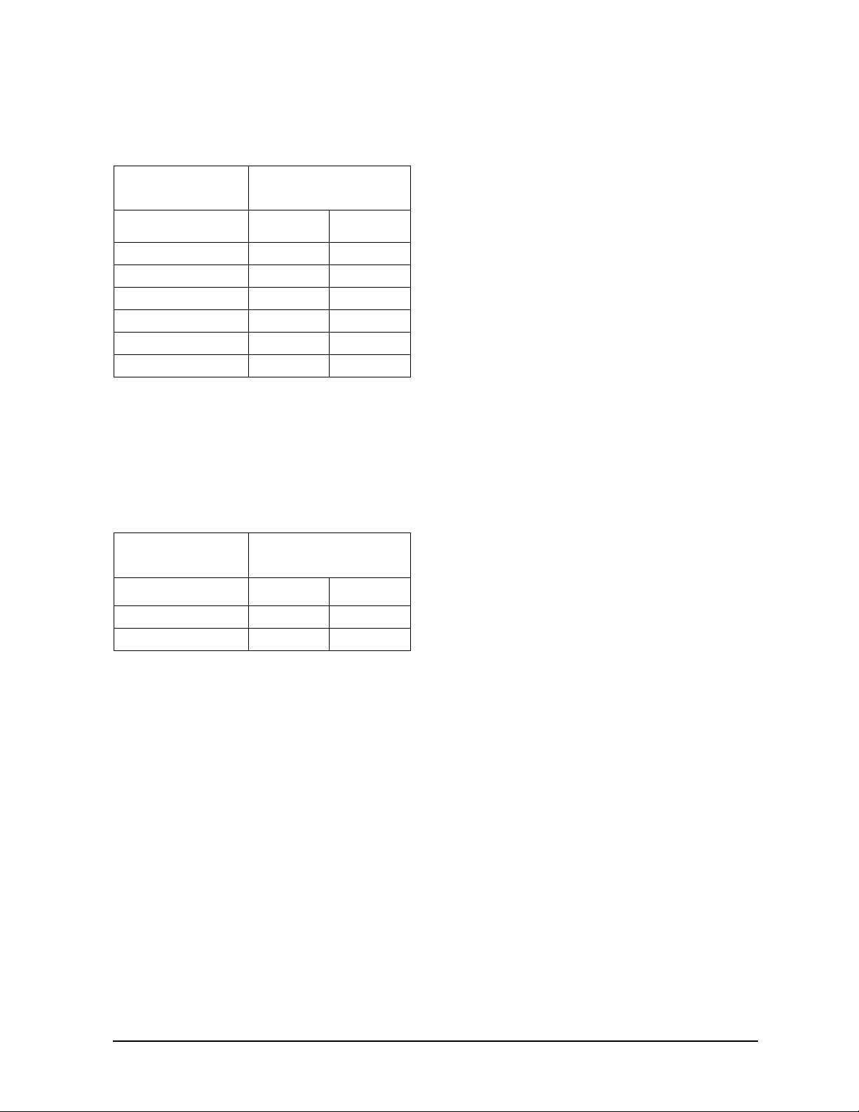
Phase Noise
Divider Mode On
Tabl e 1
Frequency 1 Hz 10 Hz 100 Hz 1 kHz 10 kHz 100 kHz
10 MHz −93 −120 −142 −152 −158 −158
100 MHz −73 −100 −122 −140 −145 −145
1. +16 dBm
E8257D Option HAR Specifications1 (25 °C)
Divider Mode Off
Standard performance per the E8257D data sheet.
Maximum Level Output Power
Divider Mode On
Typical performance see Table 4 and Table 5 on page 5.
Divider Mode Off
Table 2 Maximum Power Specification Impacts
Frequency Delta
250 kHz to 3.2 GHz −3 dB from Standard specification
> 3.2 GHz no change from standard specifications
User’s and Service Guide 3
Page 10

E8257D Option HAR Typical Performance
Typical Performance
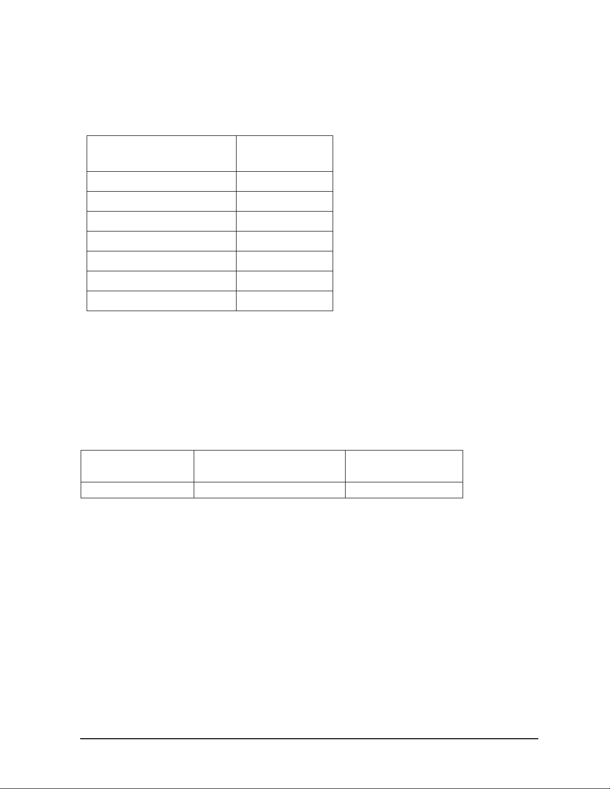
Phase Noise
Table 3 Absolute Single Sideband Phase Noise (dBc/Hz) Frequency Offset
from Carrier
1
(Typical)
2
Carrier
Frequency (MHz)
1 MHz −120 −142 −155 −160 −160 −160
10 MHz −106 −132 −148 −160 −160 −160
100 MHz −86 −112 −129 −144 −149 −149
160 MHz −81 −107 −122 −142 −145 −145
250 MHz −76 −104 −121 −138 −142 −142
500 MHz −70 −98 −115 −132 −136 −136
1. +16 dBm
Divider Mode On.
2.
1 Hz 10 Hz 100 Hz 1 kHz 10 kHz 100 kHz
Amplitude
Table 4 Option 520 Maximum Leveled Output Power1 dBm
Carrier
Frequency
1 MHz 19 19
10 MHz 19 13
100 MHz 17 11
160 MHz 17 11
250 MHz 17 10
500 MHz 16 10
Lowband Filter
Off
On
4
2
(Typical)
3
1.Amplitude accuracy is not specified in diver mode.
2.Divider Mode On.
3.Option 1EA installed. Divider mode on, without Option IEA max power is
the lower of 10 dBm, or refer to Tabl e 4.
4.For improved amplitude accuracy the lowband filters must be on.
4 User’s and Service Guide
Page 11
E8257D Option HAR Typical Performance
Table 5 Option 532 or 540 Maximum Leveled Output Power1 dBm
Carrier
Frequency
1 MHz 15 15
10 MHz 15 10
100 MHz 15 9
160 MHz 15 8
250 MHz 15 8
500 MHz 13 9
1.Amplitude accuracy is not specified in diver mode.
2.Divider Mode On.
3.Option 1EA installed. Divider mode on, without Option IEA max power is
the lower of 10 dBm, or refer to Tabl e 5.
4.For improved amplitude accuracy the lowband filters must be on.
Table 6 Harmonic Level dBc1 (Typical)
Carrier
Frequency
Lowband Filter
Off
Lowband Filter
On
4
2
2
(Typical)
3
Off On
< 10 MHz − 10 − 10
10 to 500 MHz − 10 − 55
1. Divider Mode On.
2. Harmonic levels in divider mode are high (the output
is a square wave)
User’s and Service Guide 5
Page 12

E8257D Option HAR Typical Performance
Modulation
Frequency Modulation
Table 7 Maximum FM Modulation Deviation (Typical)
Carrier Frequency kHz
> 0.98 MHz to 1.953 MHz 3.906
> 1.953 MHz to 3.906 MHz 7.8125
> 3.906 MHz to 7.813 MHz 15.625
> 7.813 MHz to 15.63 MHz 31.25
> 15.63 MHz to 31.25 MHz 62.5
> 31.25 MHz to 62.5 MHz 125
> 62.5 MHz to 125 MHz 250
> 125 MHz to 250 MHz 500
> 250 MHz to 500 MHz 1000
1.Divider Mode On.
Phase Modulation
Table 8 Maximum Phase Modulation (Typical)
Carrier Frequency
Normal Bandwidth
Mode (radians)
1
High Bandwidth
Mode (radians)
1
> 0.98 MHz to 1.953 MHz 0.0039063 0.0039063
> 1.953 MHz to 3.906 MHz 0.0078125 0.0078125
> 3.906 MHz to 7.813 MHz 0.015.625 0.015.625
> 7.813 MHz to 15.63 MHz 0.03125 0.03125
> 15.63 MHz to 31.25 MHz 0.0625 0.0625
> 31.25 MHz to 62.5 MHz 125 0.125
> 62.5 MHz to 125 MHz 250 0.250
> 125 MHz to 250 MHz 500 0.500
> 250 MHz to 500 MHz 10 1
1.Divider Mode On.
6 User’s and Service Guide
Page 13

E8257D Option HAR Typical Performance
Amplitude Modulation
AM modulation is not recommended in divider mode. In divider mode, ALC Bandwidth is
limited to 100 Hz and dynamic range is restricted below 500 MHz.
Pulse Modulation
Divider Mode On:
Standard Pulse (UNU) can not be used in divider mode. Option UNW can be used.
Divider Mode Off:
Pulse On/Off ratio is degraded by 10 dB from 2.0 to 3.2 GHz in Standard Pulse (UNU).
Option UNW is not affected.
ALC Performance
The ALC bandwidth is limited to 100 Hz in divider mode. Operation with ALC off is not
recommended.
Ramp Sweep
Ramp Sweep is unavailable with Divider Mode On.
User’s and Service Guide 7
Page 14
E8257D Option HAR Operation
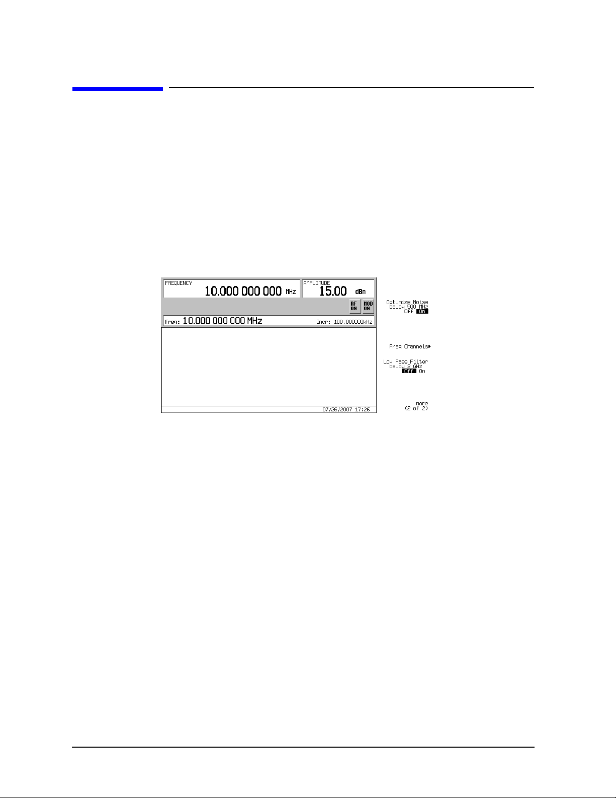
Operation
E8257D Option HAR requires firmware revision ≥ C.04.94.
To turn on the frequency divider circuitry (Divider Mode) select [Frequency] >
MORE (1 of 3) > MORE (2 of 3) > Optimize noise below 500 MHz > toggle On or Off.
The normal preset state is Off.
The SCPI command is as follows:
[:SOURce]: LFDivider ON|OFF|1|0
[:SOURce]: LFDivider?
Figure 2
Frequency Divider Circuitry
E8257D Option HAR Using the E5500 Phase Noise Measurement Subsystem
The E5500 software currently does not recognize Option HAR. To improve reference phase
noise when using your E8257D Option HAR with the E5500, manually turn the Divider
Mode On (refer to Operation), when the “Agilent E5500 Instrument Connections” window
appears.
8 User’s and Service Guide
Page 15
E8257D Option HAR Service
Service
Troubleshooting
1. Before troubleshooting E8257D Option HAR, verify that the standard instrument is
operating properly with the Divider Mode Off. If not, troubleshoot in Standard Mode.
2. For the instrument to operate properly with the Option HAR circuitry installed (Divider
Mode On or Off), licenses are needed for the following options:
•Option HAR
• Option 1EH
3. If the Phase Noise in Divider Mode is does not meet specification (refer to “Performance
Test” on page 11), replace the Divider Assembly.
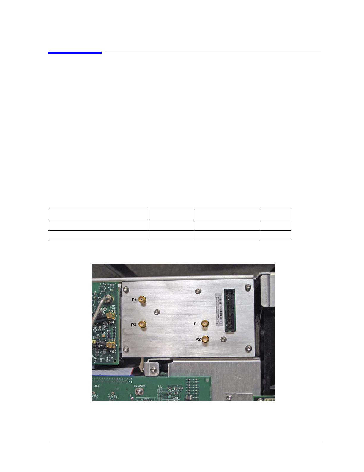
4. Measure the losses through Option HAR in Standard Mode (Divider Mode Off).
Table 9 Divider Assembly
Assembly Path Frequency Loss
Divider Assembly E8251-60433 P1 to P2 250 MHz to 3.2 GHz ≤ 3 dB
Divider Assembly E8251-60433 P4 to P3 250 MHz to 3.2 GHz ≤ 3 dB
Figure 3 Divider Assembly with Connectors Labeled
User’s and Service Guide 9
Page 16

E8257D Option HAR Service
5. If there is excessive loss in one path, replace the Divider Assembly.
6. If there is excessive loss in both paths, remove the ribbon cable from the Divider
Assembly and measure the following voltages at the end of the ribbon cable.
Pin Voltage
23 > 14.5
24 ≤ −4.5
25 > 8
26 ≤ −14.5
7. If any of the voltages are wrong, measure the same voltages on the Lowband Filter
Assembly (J6).
a. If the voltage at pin 25 is incorrect, measure the voltage on the motherboard at P142,
pin 7.
1. If the voltage at P142, pin 7 is < 8 volts, replace the Motherboard.
2. If the Motherboard is working properly, replace the Lowband Filter Assembly.
b. If the voltage on the Lowband Filter Assembly (J6) pin 23, 24 or 26 is incorrect.
1. Replace the Lowband Filter Assembly.
2. If the Lowband Filter Assembly is working properly, replace the ribbon cable from
the Lowband Filter Assembly to the Divider Assembly.
8. Set the instrument frequency to 1 MHz, Output power to maximum and RF On.
9. With all other cables connected, make the following measurements on the Divider
Assembly with a spectrum analyzer.
P2 P3
Divider Mode On Off On Off
Frequency 256 MHz 999 MHz 1 MHz 1 MHz
Amplitude −35 dBm +9 dBm +12 dBm +11 dBm
10.If the frequencies at connector P2 are incorrect.
a. Troubleshoot the standard synthesizer system.
11.If the amplitude at connector P2 is incorrect.
a. Replace the Divider Assembly.
12.If the frequencies or amplitude at connector P3 are incorrect.
a. Replace the Divider Assembly.
10 User’s and Service Guide
Page 17
E8257D Option HAR Service
Replaceable Parts
Table 10 Replaceable Parts
Description Agilent Part
Number
Option 1EH Board E8251- 60595
Div Board E8251- 60433
Ribbon Cable E8251- 60594
Cable (Frac- N to Div) E8251-20394
Cable (Div to Lowband filter) E8251- 20395
Cable (Lowband Out to Div) E8251-20396
Cable (Div to Lowband filter) E8251- 20397
• If the mother board is changed, it must be replaced with an E8251-60441 or later.
• If the modulation filter (5087-7061) is changed, reuse the thermal pad.
• If the synthesizer assembly (E8251-60328) is replaced, refer to “Appendix” on page 19 to
modify the self test limits.
Performance Test
Table 11 Performance Test Equipment
Instrument
Phase Noise System Sensitivity E5504B Option 001
Critical Specifications
(for this test)
Recommended
Model
User’s and Service Guide 11
Page 18

E8257D Option HAR Service
Setting up the E5500 Software
Step 1. If necessary, install the E5500 revision A.03.03 (or later) software.
Step 2. Open the E5500 Software User Interface.
Step 3. Select System > Asset Manager.
Step 4. Verify that the Agilent E8257D is listed under Source. If not, double-click Source
and click Next.
Step 5. In the list of Sources, select Agilent E8257D and click Next.
Step 6. In the Interface drop-down menu, select GPIB.
Step 7. In the Address field, enter the GPIB address of the E8257D. Example, 19.
Step 8. Verify that the Library field identifies Agilent Technologies VISA.
Step 9. Click Next > Finish.
Step 10. In the list of Sources, select Agilent E8257D.
Step 11. Select the icon with the green check-mark. Verify that the connection to the
selected asset has been completed. Press OK.
Step 12. Verify that the Library field identifies Agilent Technologies VISA.
Step 13. Close the Asset Manager.
Step 14. Verify that the Phase Noise System is connected as shown in Figure 4. The
connections from the 70427A should not be made at this time. The user will be
instructed to make the appropriate connections as part of the following
Performance Test procedure.
12 User’s and Service Guide
Page 19
E8257D Option HAR Service
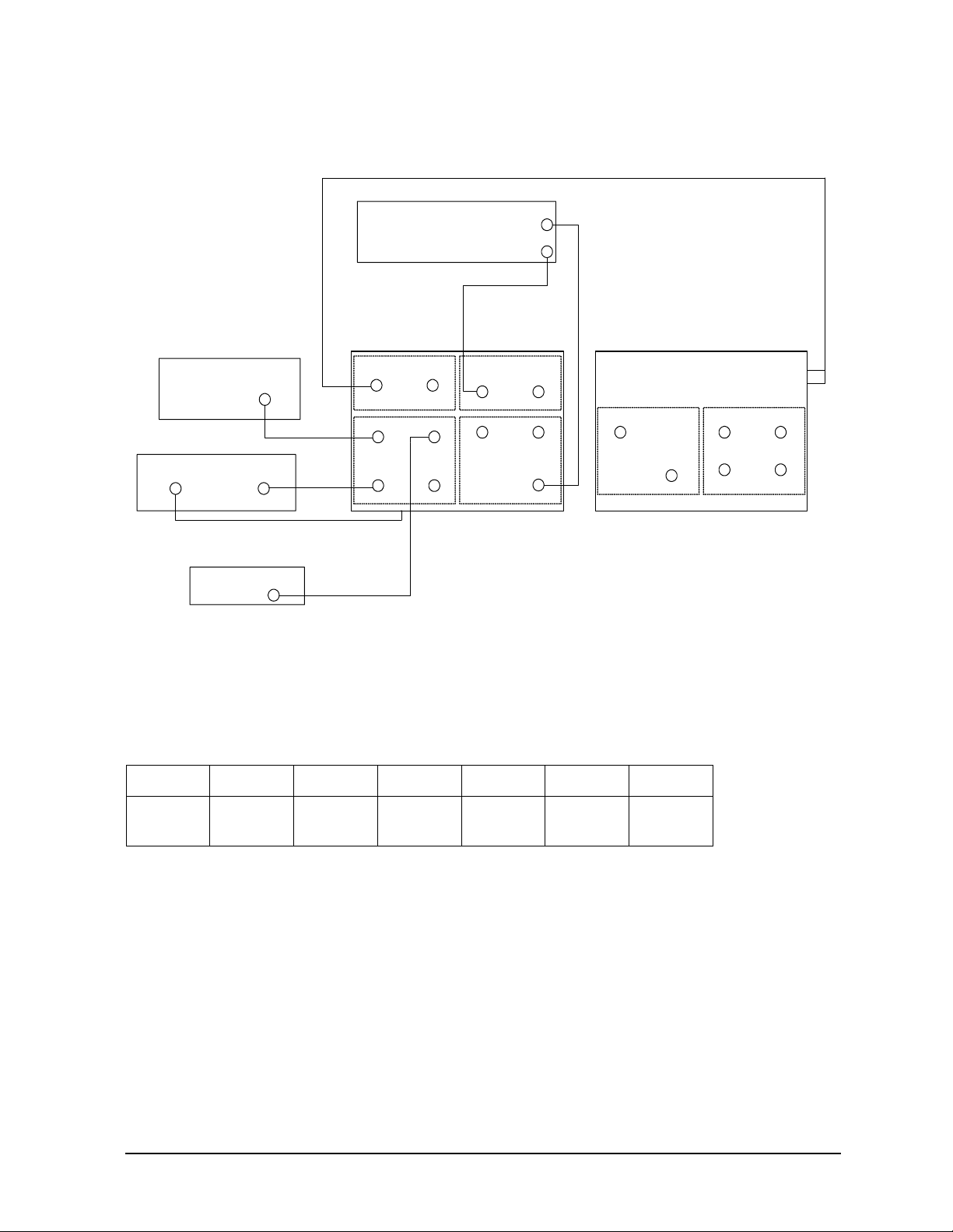
Figure 4 Test Setup Block Diagram
E8257D Option HAR under test
EXT 1 Input
RF OUTPUT 50 Ω
Spectrum Analyzer *
INPUT 50 Ω
9 kHz - 1.5 GHz
PC Controller/Digitizer *
Digitizer
Output
TO NOISE SOURCE Input on Rear Panel
Frequency Counter *
Digit izer
Input
Channel 1
70420A-001 Test Set *
SIGNAL NOISE
RF Analyzer MONITOR
ANALYZER ANALYZER
< 100 kHz < 100 MHz
REF INPUT
50 KHz -
1600 MHz
+ 15 dBm min
From
Down
Converter
1.2 -
26.5 GHz
+ 7 dBm min
To
Down
Converter
TUNE
VOLTAGE
* P/O Phase Noise Measurement System.
70427A Downconverter *
10 MHz Oven Output +18 dBm (REAR PANEL)
SIGNAL
5 MHz - 26.5 GHz
VOLTAGE CONTROL
+ 10 Volts Max
10 MHz Phase Noise Test Limits
Table 12 Phase Noi se Te st Limits
10 MHz 1 Hz 10 Hz 100 Hz 1 kHz 10 kHz 100 kHz
100 MHz +8 dBm (REAR PANEL)
AM NOISE RF Analyz er
IF
5 - 1500 MHz
µW LO
2.4 - 25.8 GHz
+10 dBm
Noise
Spec
10 MHz Test Procedure
−93 −120 −142 −152 −158 −158
Using the E5504B Phase Noise Measurement System.
Step 1. Select Define > Limit Lines.
Step 2. Enter the Noise Spec data (Table 12) in the Upper Noise Limit tab.
Step 3. Select Define > Measurement. Refer to Table 13.
User’s and Service Guide 13
Page 20

E8257D Option HAR Service
Table 13 10 MHz Phase Noise System Setup
Parameter Setting
Type and Range Tab:
Measurement Type Absolute Phase Noise
(using a phase locked loop)
Start Offset Frequency 1 Hz
Stop Offset Frequency 2 MHz (2E+6)
FFT Averages 10
FFT Quality High Resolution
Swept Quality High Resolution
Source Tab:
Carrier Source Connected Test Set
Carrier Source Frequency 10 MHz (10E+6)
Carrier Source Power +15 dBm
Detector Input Frequency No entry needed
Reference Source Power 16 dBm
VCO Tune Constant 0.1 ppm x Carrier
0.1 ppm x 10 MHz = 1 Hz/Volt
VCO Tune Range ±5 Volts
VCO Input Resistance 600 Ohms
Cal Tab:
Measure Phase Detector Constant Measure Phase Detector Constant
Calculate VCO Tune Constant Measure VCO Tune Constant
Verify calculated phase lock loop
suppression
If Limit is exceeded Use Theoretical Value
Block Diagram Tab:
Carrier Source Manual
Downconverter None
Reference Source Agilent E8257D
Phase Detector Mode Automatic Detector Selection
Test Set Tune Voltage Destination Reference Source
VCO Tune Mode DC FM
Test Set Tab:
Input Attenuation 0 dB
LNA Low Pass Filter Auto
LNA Gain Auto Gain
PLL Integrator Attenuation 0 dB
Downconverter Tab:
Input Attenuation Auto
IF Gain Auto
Microwave/Millimeter Band Microwave (0 to 26.5 GHz)
Reference Chain Reference 10 MHz
Graph Tab:
Title 10 MHz Agilent E8257D SNxxxxxxxx
Check
14 User’s and Service Guide
Page 21

E8257D Option HAR Service
Table 13 10 MHz Phase Noise System Setup
Parameter Setting
Graph Type Single- sideband Phase Noise (dBc/Hz)
X Scale Minimum 1 Hz
X Scale Maximum 100E+6
Y Scale Maximum 0
Y Scale Minimum −170
Normalize Trace Data to 1 Hz Bandwidth
Making the 10 MHz Measurement
Step 1. In the Measure drop-down menu verify that the Pause at Connect Diagram is
selected. If not, select it.
Step 2. In the Measure drop-down menu select New Measurement.
Step 3. Select Yes in the Do you want to perform a new Calibration and Measurement?
dialog box. The Agilent E5500 Instrument Connections window will appear.
Step 4. On the 70427A rear panel, remove the jumper from the 105 MHz Oven Out to 10
MHz In. Refer to Figure 4 on page 13.
Step 5. Connect the 10 MHz Oven Out on the 70427A rear panel to the Signal Input on
the 70420A.
Step 6. Turn On the Divider Mode. Refer to “Operation” on page 8
.
Step 7. Select Continue and allow Phase Noise Measurement to complete.
Step 8. Compare the estimated mean value of the trace with the noise specification line
(lower line). If the estimated mean value of the trace falls on or below the
specification line, the LNSG is regarded as having met the noise specification.
Step 9. Print the E5500 Phase Noise Plot.
Step 10. Connect the jumper that was removed in Step 4.
User’s and Service Guide 15
Page 22

E8257D Option HAR Service
100 MHz Phase Noise Test Limits
Table 14 Ph ase Noise Tes t Li mits
100 MHz 1 Hz 10 Hz 100 Hz 1 kHz 10 kHz 100 kHz
Noise
Spec
−73 −100 −122 −140 −145 −145
100 MHz Test Procedure
Using the E5504B Phase Noise Measurement System.
Step 1. Select Define > Limit Lines.
Step 2. Enter the Noise Spec data (Table 14) under the Upper Noise Limit tab.
Step 3. Select Define > Measurement. Refer to Table 15.
16 User’s and Service Guide
Page 23

E8257D Option HAR Service
Table 15 100 MHz Phase Noise System Setup
Parameter
Setting
1
Type and Range Tab:
Measurement Type Absolute Phase Noise
(using a phase locked loop)
Start Offset Frequency 1 Hz
Stop Offset Frequency 20 MHz (20E+6)
FFT Averages 10
FFT Quality High Resolution
Swept Quality High Resolution
Source Tab:
Carrier Source Connected Test Set
Carrier Source Frequency 100 MHz (100E+6)
Carrier Source Power +15 dBm
Detector Input Frequency No entry needed
Reference Source Power 16 dBm
VCO Tune Constant 0.1 ppm x Carrier
0.1 ppm x 100 MHz = 10 Hz/Volt
VCO Tune Range ±5 Volts
VCO Input Resistance 600 Ohms
Cal Tab:
Measure Phase Detector Constant Measure Phase Detector Constant
Calculate VCO Tune Constant Measure VCO Tune Constant
Verify calculated phase lock loop
suppression
If Limit is exceeded Use Theoretical Value
Check
Block Diagram Tab:
Carrier Source Manual
Downconverter None
Reference Source Agilent E8257D
Phase Detector Mode Automatic Detector Selection
Test Set Tune Voltage Destination Reference Source
VCO Tune Mode DC FM
Test Set Tab:
Input Attenuation 0 dB
LNA Low Pass Filter Auto
LNA Gain Auto Gain
PLL Integrator Attenuation 0 dB
Downconverter Tab:
Input Attenuation Auto
IF Gain Auto
Microwave/Millimeter Band Microwave (0 to 26.5 GHz)
Reference Chain Reference 10 MHz
Graph Tab:
User’s and Service Guide 17
Page 24

E8257D Option HAR Service
Table 15 100 MHz Phase Noise System Setup
Parameter
Title 100 MHz Agilent E8257D SNxxxxxxxx
Graph Type Single- sideband Phase Noise (dBc/Hz)
X Scale Minimum 1 Hz
X Scale Maximum 100E+6
Y Scale Maximum 0
Y Scale Minimum −170
Normalize Trace Data to 1 Hz Bandwidth
1.Delta settings are indicated with a bold font.
Setting
1
Making the 100 MHz Measurement
Step 1. In the Measure drop-down menu verify that the Pause at Connect Diagram is
checked. If not, select it.
Step 2. In the Measure drop-down menu select New Measurement.
Step 3. Select Yes in the Do you want to perform a new Calibration and Measurement?
dialog box. The Agilent E5500 Instrument Connections window will appear.
Step 4. Connect the 100 MHz +8 dBm Output on the 70427A rear panel to the Signal
Input on the 70420A. Refer to Figure 4 on page 13.
Step 5. Turn On the Divider Mode. Refer to “Operation” on page 8
.
Step 6. Select Continue and allow Phase Noise Measurement to complete.
Step 7. Compare the estimated mean value of the trace with the noise specification line
(lower line). If the estimated mean value of the trace falls on or below the
specification line, the LNSG is regarded as having met the noise specification.
Step 8. Print the E5500 Phase Noise Plot.
18 User’s and Service Guide
Page 25

E8257D Option HAR Appendix
Appendix
Modifying Synthesizer Self Test Limits
This procedure allows you to modify the synthesizer A6 Frac N self test limits for test 704,
after replacing the A6 Frac N assembly. (Firmware versions C.04.70 and later).
Open a browser window and type the IP address of the instrument, followed by ‘/update’ as
shown: http://xxx.xxx.xxx.xxx/update.
1. Enter the following text in the “Manual Update” form as shown below.
ll "SYNTH", 14, 0.5
ul "SYNTH", 14, 13.5
ll "SYNTH", 15, 0.5
ul "SYNTH", 15, 13.5
ll "SYNTH", 16, 1.5
ul "SYNTH", 16, 13.5
ky 53004
2. Press Execute (next to the manual update form). When the update is complete
“Operation Completed” will be displayed.
3. Cycle the power on the instrument.
If you need to revert to the standard self test limits, use the following sequence:
ll "SYNTH", 14, 1.5
ul "SYNTH", 14, 13.5
ll "SYNTH", 15, 3.0
ul "SYNTH", 15, 13.5
ll "SYNTH", 16, 2.0
ul "SYNTH", 16, 13.5
ky 51873
User’s and Service Guide 19
Page 26

E8257D Option HAR Safety and Regulatory Information
Safety and Regulatory Information
Introduction
Review this product and related documentation to familiarize yourself with safety
markings and instructions before you operate the instrument. The documentation contains
information and warnings that must be followed by the user to ensure safe operation and
to maintain the product in a safe condition.
Cleaning the Instrument
WAR NING
To prevent electrical shock, disconnect the Agilent Technologies
E8257D Option HAR from mains before cleaning. Use a dry cloth or
one slightly dampened with water to clean the external case parts.
Do not attempt to clean internally.
Connector Care and Cleaning
Cleaning connectors with alcohol shall only be done with the instrument power cord
removed, and in a well ventilated area. Allow all residue alcohol moisture to evaporate and
the fumes to dissipate prior to energizing the instrument.
WAR NING
Use isopropyl alcohol with adequate ventilation and avoid contact with eyes,
skin, and clothing. It causes skin irritation, may cause eye damage, and is
harmful if swallowed or inhaled. It may be harmful if absorbed through the skin.
Wash thoroughly after handling.
Keep isopropyl alcohol away from heat, sparks, and flame. Store in a
tightly closed container. It is extremely flammable. In case of fire, use
alcohol foam, dry chemical, or carbon dioxide; water may be
ineffective.
In case of spill, soak up the sand or earth. Flush spill area with water.
Dispose of isopropyl alcohol in accordance with all applicable
federal, state, and local environmental regulations.
Declaration of Conformity
For a copy of the manufacturer’s Declaration of Conformity for this apparatus, contact your
local Agilent Technologies office or sales representative. Refer to “Contacting Agilent Sales
and Service Offices” on page 26.
20 User’s and Service Guide
Page 27

E8257D Option HAR Safety and Regulatory Information
Statement of Compliance
This instrument has been designed and tested in accordance with IEC Publication 1010,
Safety Requirements for Electronic Measuring Apparatus, and has been supplied in a safe
condition. The instruction documentation contains information and warnings which must
be followed by the user to ensure safe operation and to maintain the instrument in a safe
condition.
Shipping Instructions
You must always call the Agilent Technologies Instrument Support Center to initiate
service before retuning your instrument to a service office. See “Contacting Agilent Sales
and Service Offices” on page 26. Always transport or ship the instrument using the
original packaging if possible. If not, comparable packaging must be used. Attach a
complete description of the failure symptoms.
Compliance with Canadian EMC Requirements
This ISM device complies with Canadian ICES-001.
Cet appareil ISM est conforme a la norme NMB du Canada.
Compliance with German FTZ Emissions Requirements
This product complies with the German FTZ 526/527 Radiated Emissions and Conducted
Emission requirements.
Compliance with German Noise Requirements
This is to declare that this instrument is in conformance with the German Regulation on
Noise Declaration for Machines (Laermangabe nach der Maschinenlaermrerordnung-3.
GSGV Deutschland).
Acoustic Noise Emission/Geraeuschemission
LpA<70 dB Lpa<70 dB
Operator Position am Arbeitsplatz
Normal Operation normaler Betrieb
per ISO 7779 nach DIN 45635 t. 19
User’s and Service Guide 21
Page 28

E8257D Option HAR Safety and Regulatory Information
General Safety Considerations
Safety Earth Ground
WAR NING
Before Applying Power
Verify that the product is configured to match the available main power source. If this
product is to be powered by autotransformer, make sure the common terminal is connected
to the neutral (grounded) side of the ac power supply.
Cautions applicable to this instrument.
CAUTION
CAUTION
This is a Safety Class I product (provided with a protective earthing
ground incorporated in the power cord). The mains plug shall only
be inserted in a socket outlet provided with a protective earth
contact. Any interruption of the protective conductor, inside or
outside of the instrument, will make the instrument dangerous.
Intentional interruption is prohibited.
Always use the three-prong ac power cord supplied with this instrument.
Failure to ensure adequate earth grounding (by not using this cord) can cause
instrument damage.
This product is designed for use in Installation Category II and Pollution
Degree 2 per IEC 61010 Second Edition and 664 respectively.
CAUTION
CAUTION
This instrument has autoranging line voltage input; be sure the supply
voltage is within the specified range.
Ventilation Requirements: When installing the instrument in a cabinet, the
convection into and out of the instrument must not be restricted. The ambient
temperature (outside the cabinet) must be less than the maximum operating
temperature of the instrument by 4 °C for every 100 watts dissipated in the
cabinet. If the total power dissipated in the cabinet is greater than 800 watts,
forced convection must be used.
22 User’s and Service Guide
Page 29

E8257D Option HAR Safety and Regulatory Information
Servicing
Warnings applicable to this instrument
WAR NING
To prevent electrical shock, disconnect the Agilent Technologies
E8257D Option HAR from the mains before cleaning. Use a dry cloth
or one slightly dampened with water to clean the external case parts.
Do not attempt to clean internally.
WAR NING
This is a Safety Class I product (provided with a protective earthing
ground incorporated in the power cord). The mains plug shall be
inserted only into a socket outlet provided with a protective earth
contact. Any interruption of the protective conductor, inside or
outside the product is likely to make the product dangerous.
Intentional interruption is prohibited.
WAR NING
WAR NING
These servicing instructions are for use by qualified personnel only.
The opening of covers or removal of parts is likely to expose
dangerous voltages. Disconnect the instrument from all voltage
sources while it is being opened.
WAR NING
This product is designed for use in Installation Category II and
Pollution Degree 2 per IEC 61010-1: 2001.
.
WAR NING
WAR NING
No operator serviceable parts inside. Refer servicing to qualified
personnel.
If this product is not used as specified, the protection provided by
the equipment could be impaired. This product must be used in a
normal condition (in which all means for protection are intact) only.
User’s and Service Guide 23
Page 30
E8257D Option HAR Electrostatic Discharge Protection
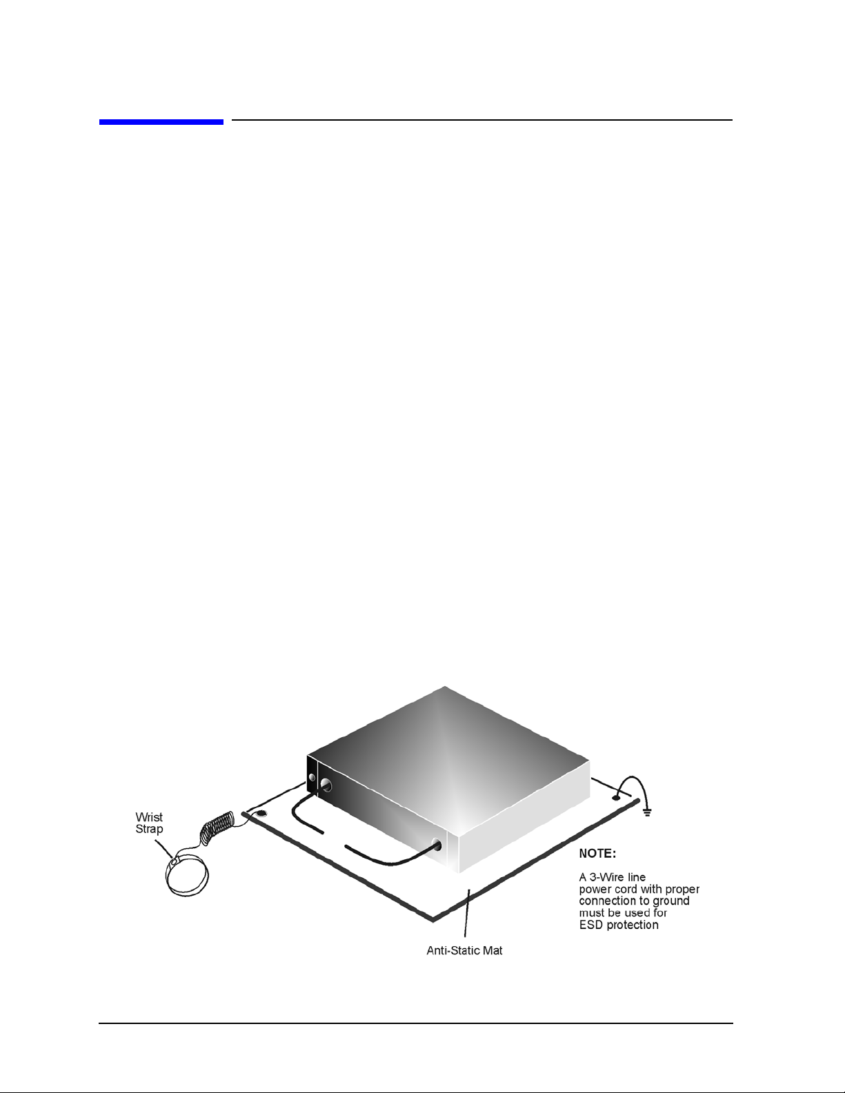
Electrostatic Discharge Protection
Protection against electrostatic discharge (ESD) is essential while removing assemblies
from or connecting cables to the network analyzer. Static electricity can build up on your
body and can easily damage sensitive internal circuit elements when discharged. Static
discharges too small to be felt can cause permanent damage. To prevent damage to the
instrument:
• always have a grounded, conductive table mat (9300-0797) in front of your test
equipment.
• always wear a grounded wrist strap (9300-1367) with grounding cord (9300-0980),
connected to a grounded conductive table mat, having a 1 MΩ resistor in series with it,
when handling components and assemblies or when making connections.
• always wear a heel strap (9300-1126) when working in an area with a conductive floor.
If you are uncertain about the conductivity of your floor, wear a heel strap.
• always ground yourself before you clean, inspect, or make a connection to a
static-sensitive device or test port. You can, for example, grasp the grounded outer shell
of the test port or cable connector briefly.
• always ground the center conductor of a test cable before making a connection to the
analyzer test port or other static-sensitive device. This can be done as follows:
1. Connect a short (from your calibration kit) to one end of the cable to short the center
conductor to the outer conductor.
2. While wearing a grounded wrist strap, grasp the outer shell of the cable connector.
3. Connect the other end of the cable to the test port and remove the short from the
cable.
Figure 5 ESD Protection Setup
24 User’s and Service Guide
Page 31

E8257D Option HAR Regulatory Information
Regulatory Information
Instrument Markings
The instruction documentation symbol. The product is marked with this symbol
when it is necessary for the user to refer to the instructions in the documentation.
This symbol indicates that the instrument requires alternating current (ac) input.
This symbol indicates separate collection for electrical and electronic equipment,
mandated under EU law as of August 13, 2005. All electric and electronic equipment
are required to be separated from normal waste for disposal (Reference WEEE
Directive, 2002/96/EC).
This symbol indicates that the power line switch is ON.
This symbol indicates that the power line switch is in the STANDBY position.
ICES/NMB-001
This symbol indicates that the power line switch is in the OFF position.
This symbol is used to identify a terminal which is internally connected to the
product frame or chassis.
The CE mark is a registered trademark of the European Community. (If accompanied
by a year, it is when the design was proven.)
The CSA mark is a registered trademark of the Canadian Standards Association.
This instrument complies with Canada: CSA 22.2 No. 000000061010-1, Second
Edition.
This is a symbol of an Industrial Scientific and Medical Group 1 Class A product.
This is a marking to indicate product compliance with the Canadian
Interference-Causing Equipment Standard (ICES-001).
Direct Current.
This is a required mark signifying compliance with an EMC requirement. The C-Tick
mark is a registered trademark of the Australian Spectrum Management Agency.
China RoHS regulations include requirements related to packaging, and require
compliance to China standard GB18455-2001.
This symbol indicates compliance with the China RoHS regulations for
paper/fiberboard packaging.
User’s and Service Guide 25
Page 32

E8257D Option HAR Contacting Agilent Sales and Service Offices
Contacting Agilent Sales and Service Offices
Assistance with test and measurement needs, and information on finding a local Agilent
office are available on the Internet at:
http://www.agilent.com/find/assist
You can also purchase accessories or documentation items on the Internet at:
http://www.agilent.com/find
If you do not have access to the Internet, contact your field engineer.
NOTE
In any correspondence or telephone conversation, refer to the product by its
model number and full serial number. With this information, the Agilent
representative can determine whether your unit is still within its warranty
period.
26 User’s and Service Guide
 Loading...