

Page 1
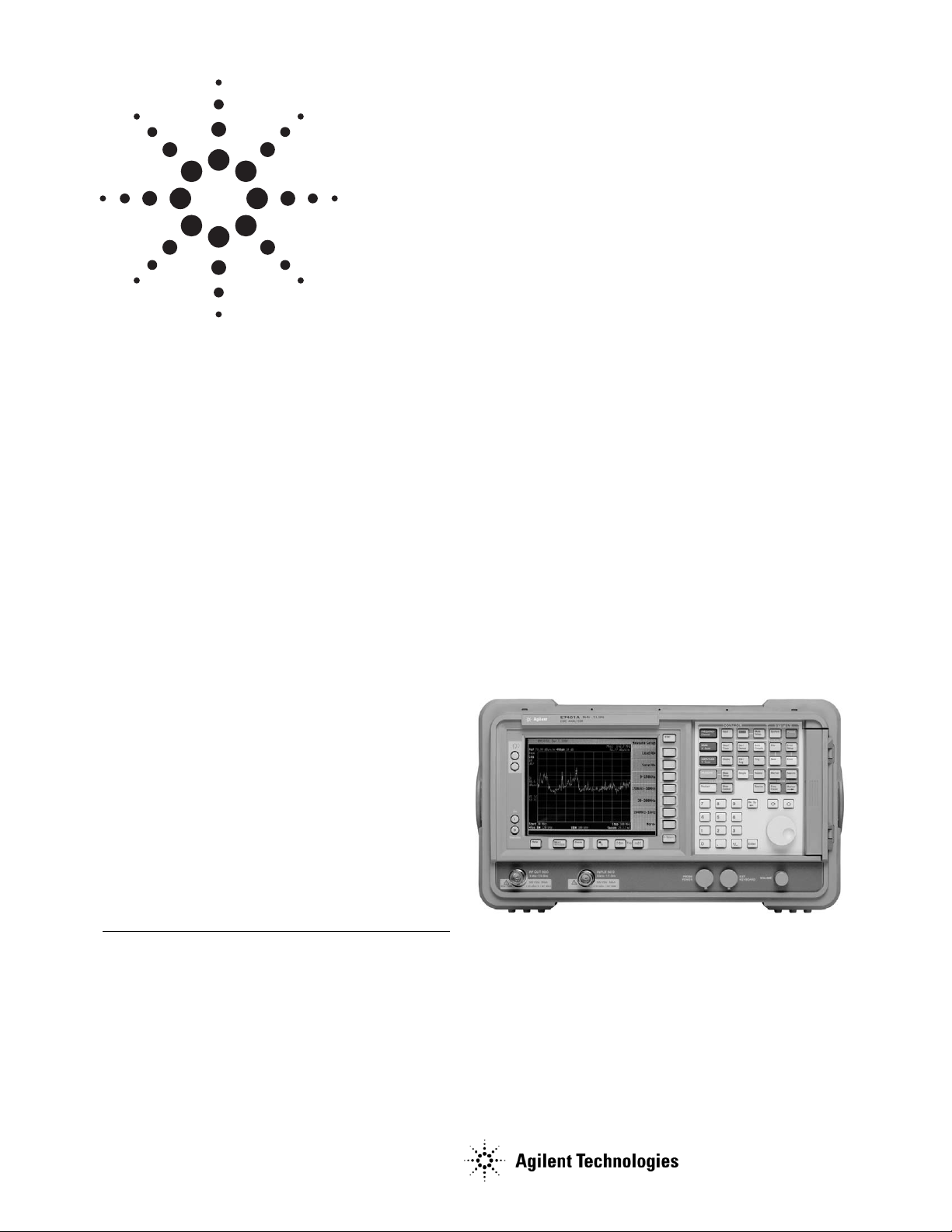
These specifications apply to the Agilent
Technologies E7402A and E7405A EMC
analyzers.
Frequency Specifications
Frequency range
E7402A
dc coupled 30 Hz1to 3.0 GHz
ac coupled 100 kHz1to 3.0 GHz
E7405A
Band LO harmonic = N
0 1- dc coupled 30 Hz1to 3.6 GHz
ac coupled 100 MHz to 3.6 GHz
1 1- 2.85 GHz to 6.7 GHz
2 2- 6.2 GHz to 13.2 GHz
3 4- 12.8 GHz to 19.2 GHz
4 4- 18.7 GHz to 26.5 GHz
Frequency reference
Aging ±1 x 10⁻⁷/year
Temperature stability ±1 x 10
-8
Settability ±1 x 10
-8
Frequency readout accuracy
(start, stop, center, marker) ±(frequency indication
x frequency reference error
2
+ span accuracy + 15% of RBW
+ 10 Hz) + 1 Hz x N
3
Specifications
All specifications apply over 0 °C to +55 °C unless otherwise noted and are covered by the product warranty. The
analyzer will meet its specifications when: it’s within the
one year calibration cycle, AUTO ALIGN [ALL] is selected,
stored a minimum 2 hours within the operating temperature range, turned on for at least 5 minutes, and Align Now
RF has been run once every 24 hour period. Typical performance describes the level at which 80% of the units will meet
or exceed with a 95% confidence level over 20 to 30 °C, but is
not covered in the product warranty. Characteristics
describe expected product performance levels that are not
covered in the product warranty.
Agilent
E7400 A-series EMC Analyzers
Data Sheet
1. Characteristic
2. Frequency reference error = (aging rate x period of time since
adjustment + settability + temperature stability
3. N = LO harmonic mixing mode
Page 2

2
Marker frequency counter
1
Accuracy
2
±(marker frequency x frequency
reference error3+ counter resolution)
Counter Resolution Selectable from 1 Hz to 100 kHz
Frequency span
Range 0 Hz (zero span), 100 Hz x N4to the
range of the spectrum analyzer
Resolution 2 Hz x N
4
Accuracy(> 2000 sweep points)
Sweep type linear ±0.5% of span
Sweep type log ±2% of span (characteristic)
Sweep time
Range
Span > 0 Hz 1 ms to 4000 s
Span = 0 Hz 50 ns5to 4000 s
Accuracy ±1%
Sweep trigger Free run, single, line, video, external,
delay, offset, and gate (Option 1D6)
Delay trigger range 1 µs to 400 s
Sweep (trace) point
range 101 to 8192
Span = 0 Hz 2 to 8192
Resolution bandwidth 1 Hz to 3 MHz (-3 dB) in
1-3-10 sequence
6
5 MHz (-3 dB) bandwidth
200 Hz6, 9 kHz, 120 kHz, 1 MHz
(-6 dB) EMI bandwidths
1 MHz (impulse) EMI bandwidth
Accuracy
1 Hz to 300 MHz (-3 dB) ±10%
1 kHz to 3 MHz (-3 dB) ±15%
5 MHz (-3 dB) ±30%
200 Hz (-6 dB) ±10%
9 kHz to 120 kHz (-6 dB) ±20%
1 MHz (-6 dB) ±10%
1 MHz (impulse) ±15%
Selectivity (characteristic)
10 Hz to 300 Hz (-3 dB) < 5:1 (-60 dB/-3 dB)
(Digital, approximately
Gaussian-shaped)
1 kHz to 3 MHz (-3 dB) < 5:1 (-60 dB/-3 dB)
(approximately
Gaussian-shaped)
200 Hz (-6 dB) < 3:1 (-40 dB/-6 dB)
(Digital, Kaizer Windows)
9 kHz, 120 kHz, 1 MHz (-6 dB) < 10:1 (-60 dB/-6 dB)
(approximately
Gaussian-shaped)
1 MHz (impulse) < 10:1 (-60 dB/-6 dB)
(approximately
Gaussian-shaped)
Video bandwidth range 30 Hz to 3 MHz7in 1-3-10
sequence
1, 3, 10 Hz for RBW’s < 1 kHz
Stability
Noise sidebands (1 kHz RBW, 30 Hz VBW and sample
detector)
Stability specifications
Specified Typical
≥ 1 kHz na -78 dBc/Hz
8
≥ 10 kHz ≤ -90 dBc/Hz
8
-94 dBc/Hz
8
> 20 kHz ≤ -100 dBc/Hz
8
-105 dBc/Hz
8
> 30 kHz ≤ -106 dBc/Hz
8
-112 dBc/Hz
8
> 100 kHz ≤ -118 dBc/Hz
8
-122 dBc/Hz
8
> 1 MHz ≤ -125 dBc/Hz
8
-127 dBc/Hz
8
> 5 MHz ≤ -127 dBc/Hz
8
-129 dBc/Hz
8
> 10 MHz ≤ -131 dBc/Hz
8
-136 dBc/Hz
8
Residual FM
1 kHz RBW, 1 kHz VBW ≤ 100 x N4Hz pk-pk in 100 ms
10 Hz RBW, 10 Hz VBW ≤ 2 x N4Hz pk-pk in 20 ms
System-related sidebands
≥ 30 kHz offset from CW signal ≤ -65 dBc + 20 Log N
4
1. Not available in RBW < 1kHz
2. Marker level to DANL > 25 dB, Span ≤ 1.5 GHz, RBW/Span ≥ 0.002
3. Frequency reference error = (aging rate x period of time since adjustment
+ settability + temperature stability
4. N = LO harmonic mixing mode
5. RBW ≥1 kHz, 2 sweep points
6. 1 Hz to 300 Hz are only available in spans of ≤ 5 MHz. This bandwidth is
not usable when the tracking generator is turned on (Option 1DN).
7. Characteristic
8. Add 20 log(N) for frequencies > 6.7 GHz.
-70
Typical performance
Spec
-90
dBc/Hz
-110
-130
1k 10k 100k 1M
Offset (Hz)
Page 3

3
Amplitude specifications
Amplitude range
Measurement range Displayed average noise level
(DANL) to maximum safe input
level
Input attenuator range
E7402A 0 to 65 dB (75 dB1), in 5 dB steps
E7405A 0 to 65 dB, in 5 dB steps
Maximum safe input level
Average continuous power +30 dBm (1 W)
Peak pulse power +50 dBm (100 W)
(input attenuator ≥ 30 dB)
Maximum dc 0 Vdc (dc coupled)
50 V (ac coupled)
1 dB gain compression (total power at input mixer2)
≥ 50 MHz 0 dB
≥ 6.7 GHz -3 dB
≥ 13.2 GHz -5 dB
Display range
Log Scale 0.1, 0.2, 0.5 dB/division and 1 to 20 dB/
division in 1 dB steps; ten divisions
displayed
RBW ≥ 1kHz 0 to -85 dB from reference level is calibrated
RBW ≤ 300 Hz 0 to -1205 dB from reference level is calibrated
Linear scale 10 divisions
Scale units dBm, dBmV, dBµV, dBµA, Amps, Volts and
Watts
Marker readout resolution
Log scale
0 to -85 dB 0.04 dB
0 to -120 (RBW ≤ 300 Hz 0.04 dB
Linear scale 0.01% of reference level
Fast sweep times for zero span (Option AYX)
Log Scale, 0 to -85 dB 0.3 dB
Linear 0.3 % of reference level
1. Characteristic
2. Mixer power level (dBm) = input power (dBm) – input attenuator (dB)
3. Typical
4. 0 to 50 dB for RBWs ≤ 300 Hz and span = 0 Hz, or when auto ranging is off,
or 0 to 30 dB for RBW = 200 Hz.
5. 0 to –70 dB range when span = 0 Hz, when RBW = 200 Hz, or when IF gain
is fixed.
Display average noise level (DANL)
1 kHz 10 Hz 1 kHz 10 Hz 1 Hz
RBW RBW w/preamp w/preamp w/preamp
on on, typical on, typical
E7402A
30 Hz to 9 kHz
3
na ≤ -93 na na na
9 kHz to 100kHz
3
na ≤ -109 na na na
100 kHz to 1 MHz
3
na ≤ -135 na na na
1 MHz to 10 MHz
3
≤ -117 ≤ -136 na ≤ -152 ≤ -162
10 MHz to 1 GHz ≤ -117 ≤ -136 ≤ -152
4
≤ -156 ≤ -166
1 GHz to 2 GHz ≤ -116 ≤ -135 ≤ -153
4
≤ -156 ≤ -166
2 GHz to 3 GHz ≤ -114 ≤ -133 ≤ -151
4
≤ -154 ≤ -164
E7405A
30 Hz to 9 kHz
3
na ≤ -93 na na na
9 kHz to 100kHz
3
na ≤ -109 na na na
100 kHz to 1 MHz
3
na ≤ -135 na na na
1 MHz to 10 MHz
3
≤ -117 ≤ -137 na ≤ -155 ≤ -165
10 MHz to 1 GHz ≤ -116 ≤ -135 ≤ -151
4
≤ -157 ≤ -167
1 GHz to 2 GHz ≤ -116 ≤ -131 ≤ -151
4
≤ -155 ≤ -165
2 GHz to 3 GHz ≤ -112 ≤ -131 ≤ -149
4
≤ -152 ≤ -162
3 GHz to 6 GHz ≤ -112 ≤ -131 na na na
6 GHz to 12 GHz ≤ -111 ≤ -130 na na na
12 GHz to 22 GHz ≤ -107 ≤ -126 na na na
22 GHz to 26.5 GHz ≤ -106 ≤ -125 na na na
Page 4

4
Frequency response (10 dB input attenuation)
Absolute1Typical Relative
flatness
2
30 Hz to 3 GHz
3
±0.5 dB na ±0.5 dB
3.0 GHz to 6.7 GHz ±1.5 dB ±0.39 dB ±1.3 dB
6.7 GHz to 13.2 GHz ±2.0 dB ±0.68 dB ±1.8 dB
13.2 GHz to 26.5 GHz ±2.0 dB ±0.86 dB ±1.8 dB
Input attenuation switching uncertainty at 50 MHz
Attenuation setting
0 dB to 5 dB ±0.3 dB
10 dB Reference
15 dB ±0.3 dB
20 to 65 dB ±(0.1 dB + 0.01 x attenuator setting)
Absolute amplitude accuracy Typical
At reference settings 4±0.34 dB ±0.13 dB
Preamp on
5
±0.37 dB ±0.14 dB
Overall amplitude ±(0.54 dB + absolute
accuracy
6
frequency response)
RF input VSWR3(at tuned frequency, 10 dB attenuation)
E7402A
100 Hz to 100 kHz 1.1:1
100 kHz to 3 GHz 1.4:1
E7405A
100 Hz to 100 kHz 1.1:1
100 kHz to 6.7 GHz 1.3:1
6.7 GHz to 13.2 GHz 1.5:1
13.2 GHz to 22 GHz 2:1
22 GHz to 26.5 GHz 2.2:1
Resolution bandwidth switching uncertainty
(Referenced to 1 kHz RBW, at reference level)
10 Hz to 3 MHz RBW ±0.3 dB
5 MHz RBW ±0.6 dB
10 Hz to 300 Hz RBW ±0.3 dB
Reference level
Range -149 dBm to max. mixer level
+ attenuator setting
Resolution
Log scale ±0.1 dB
Linear scale ±0.12% of reference level
Accuracy (reference level ±0.3 dB (-10 dBm to –60 dBm)
-attenuator setting ±0.5 dB (-60 dBm to –85 dBm)
+ preamp gain) ±0.7 dB (-85 dBm to –90 dBm)
Display scale fidelity
Log maximum cumulative
RBW ≥ 1 kHz
dB below reference level Typical
0 dB (reference) ±0.00 dB ±0.00 dB
> 0 dB to 10 dB ±0.3 dB ±0.08 dB
> 10 dB to 20 dB ±0.4 dB ±0.09 dB
> 20 dB to 30 dB ±0.5 dB ±0.10 dB
> 30 dB to 40 dB ±0.6 dB ±0.23 dB
> 40 dB to 50 dB ±0.7 dB ±0.35 dB
> 50 dB to 60 dB ±0.7 dB ±0.35 dB
> 60 dB to 70 dB ±0.8 dB ±0.39 dB
> 70 dB to 80 dB ±0.8 dB ±0.46 dB
> 80 dB to 85 dB ±1.15 dB ±0.79 dB
RBW ≤ 300 Hz (span > 0 Hz)
0 dB to 98 dB ±(0.3 dB + 0.01 x dB from
reference level)
≥ 98 dB to 120 dB ±(2.0 dB from reference level)
3
Log incremental accuracy
0 dB to 80 dB
7
±0.4 dB/4 dB from reference level
Linear accuracy ± 2% of reference level
Linear to log switching ±0.15 dB at reference level
1. Referenced to 50 MHz amplitude reference (20 °C to 30 °C)
2. Reference to midpoint between highest and lowest frequency response
deviations. (20 °C to 30 °C)
3. Characteristic
4. Reference level -20 dBm; input attenuation 10 dB; center frequency 50 MHz;
RBW 1 kHz; VBW 1 kHz; scale linear or log; span 2 kHz; sweep time
coupled, sample director, signal at reference level.
5. 1 Hz to 300 Hz are only available in spans of ≤ 5 MHz and are not usable
with tracking generator Option 1DN.
6. For reference levels 0 to 50 dBm; input attenuation 10 dB; dc coupled; RFW
1 kHz; VBW 1 kHz; scale loge range 0 to -50 dB from reference level;
sweeptime coupled; signal input 0 to 50 dB; spsn ≤ 20 kHz.
7. 0 to 50 dB for RBWs ≤ 300 Hz and span = 0 Hz, or when auto ranging is off,
or 0 to 30 dB for RBW = 200 Hz.
Page 5

5
Spurious responses
Second harmonic distortion
10 MHz to 500 MHz < -65 dBc for -30 dBm tone at
input mixer
1
500 MHz to 1.5 GHz < -75 dBc for -30 dBm tone at
input mixer
2
1.5 GHz to 2.0 GHz < -85 dBc for -10 dBm tone at
input mixer
2
> 2.0 GHz < -100 dBc for -10 dBm tone at
input mixer1(or below displayed average noise level)
Third order intermodulation distortion
100 MHz to 6.7 GHz < -85 dBc for two -30 dBm tones
at input mixer 1and > 50 kHz
separation
> 6.7 GHz < -75 dBc for two -30 dBm tones
at input mixer 1and > 50 kHz
separation
Other input related spurious
< -65 dBc, for -20 dBm tone at
input mixer
1
Residual responses (input terminated and 0 dB attenuation)
150 kHz to 6.7 GHz < -90 dBm
Amplitude ref. output
Amplitude -20 dBm (nominal)
FM demodulation
3
Input level -60 dBm + attenuator setting
Signal level 0 to -30 dB below reference
level
Quasi-peak detector specifications
The EMC analyzer displays the quasi-peak amplitude of a pulse
radio frequency on continuous wave signals. Amplitude response
conforms with Publication 16 of Comite International Special des
Perturbations Radioelectrique (CISPR) Section 1, Clause 2, as indicated in the relative quasi-peak response table.
Relative quasi-peak response to a CISPR pulse (dB)
Pulse repetition 120 kHz EMI BW 9 kHz EMI BW 200 Hz EMI BW
frequency (Hz) .03 to 1 GHz 0.150 to 30 MHz 9 kHz to 150 kHz
1000 +8.0 ±1.0 +4.5 ±1.0 –––
100 0 dB reference 40 dB reference 4+4.0 ±1.0
60 ––– ––– +3.0 ±1.0
25 ––– ––– 0 dB reference
4
20 -9.0 ±1.0 -6.5 ±1.0 –––
10 -14 ±1.5 -10.0 ±1.5 -4.0 ±1.0
5 ––– ––– -7.5 ±1.5
2 -26 ±2.0 -20.5 ±2.0 -13.0 ±2.0
1 ––– -22.5 ±2.0 -17.0 ±2.0
Isolated pulse ––– -23.5 ±2.0 -19.0 ±2.0
General specifications
Temperature range
Operating 0° C to +55° C
Storage -40° C to +75° C
EMI compatibility Conducted and radiated emis-
sions is in compliance with
CISPR Pub. 11/1990 Group 1
Class B
5
Audible noise < 40 dBa pressure and
< 4.6 Bels power (ISODP7779)
Military specification Type tested to the environmental
specifications of MIL-PRF28800F, class 3
Power requirements
ON (line1) 90 to 132 V rms, 47 to 440 Hz
195 to 250 V rms, 47 to 66 Hz
Power consumption < 300 W
Standby (line 0) Power consumption < 5 W
DC operation
Voltage 12 to 20 Vdc
Power consumption < 200 W
Measurement speed
E7402A E7405A
Local measurement rate 6≥ 45/sec ≥ 40/sec
Remote measurement as
GPIB transfer rate
7
≥ 45/sec ≥ 40/sec
RF center frequency
tuning time
8
≥ 75/ms ≥ 75/ms
Data storage (nominal)
Internal 200 traces
9
or states
External (floppy) 200 traces 9or states
1. Mixer power level (dBm) = input power (dBm) – input attenuator (dB)
2. Not available in RBW < 1kHz
3. Characteristic
4. Reference pulse amplitude accuracy relative a 66 µV CW signal
< 1.5 dB as specified in CISPR Pub 16 CISPR reference pulse: 0.44 µVs
for 30 MHz to 1 GHz, 0.316 µVs for 150 kHz to 30 MHz, 13.5 µVs for
9 kHz to 150 kHz
5. Meets Class A performance during dc operation or serial number
US41110000 or lower.
6. Characteristic; factory preset, fixed center frequency, sweep points =
101 auto align off, RBW = 1 MHz, stop frequency ≤ 3 GHz, span >
10 MHz and ≤ 600 MHz.
7. Characteristic; factory preset, fixed center frequency, sweep points =
101 auto align off, RBW = 1 MHz, stop frequency ≤ 3 GHz, span =
20 MHz, GPIB interface, display and markers off, fixed center frequency, single sweep
8. Characteristic; includes center frequency tuning and measurement plus
GPIB transfer times, stop frequency ≤ 3 GHz, sweep points = 101,
display and markers off, single sweep
9. When storing a 401-point trace plus the instrument state
Page 6

6
Weight (without options)
E7402A 14.9 kg (32.9 lbs.)
E7405A 17.1 kg (37.7 lbs.)
Dimensions
Without handle 222 mm(H) x 409 mm(D) x 373
mm(W)
With handle (max.) 222 mm(H) x 516 mm(D) x 416
mm(W)
Inputs/outputs
Front panel connectors
Input 50 Ω type N (f)
Option BAB 50 Ω APC 3.5 (m)
RF Out 50 Ω type N (f)
Probe power +15 Vdc, -12.6 Vdc at 150 mA max.
characteristic
Ext. keyboard 6-pin mini-DIN, PC keyboards (for
entering screen titles and file names)
Speaker front-panel knob controls volume
Headphone 3.5 mm (1/8 inch) miniature audio jack
Power output 0.2 W into 4 Ω
1
Amptd ref. output 50 Ω, BNC (f)
Rear panel connectors
10 MHz ref out 50 Ω, BNC (f), > 0 dBm
1
10 MHz ref in 50 Ω, BNC (f), -15 to +10 dBm
1
Gate trig/ext. trig in BNC (f), 5 V TTL
Gate hi swp out BNC (f), 5 V TTL
VGA output VGA compatible monitor, 15-pin D-SUB,
(31.5 kHz horizontal, 60 Hz vertical sync
rates, non-interlaced) Analog RGB 640 x
480
IF and sweep ports
Aux IF output BNC (f), 21.4 MHz, nominal -10 to
-70 dBm1(uncorrected)
Aux video out BNC (f), 0 to 1 V1(uncorrected)
Hi swp In BNC (f), low stops sweep (5 V TTL)
Hi swp out BNC (f), (5 V TTL)
Swp out BNC (f), 0 to +10 V1ramp
GPIB interface
Standard (Option A4H) IEEE-488 bus connector
Serial interface
(Option 1AX) RS-232, 9-pin D-SUB (m)
Parallel interface
Standard 25-pin D-SUB (f), printer port only
1. Characteristic
Page 7

7
Option specifications
Option 1DN tracking generator
Frequency range 9 kHz to 3.0 GHz
Output power level range
Range -2 to -66 dBm
Resolution 0.1 dB
Absolute accuracy ±0.75 dB
(at 50 MHz)
Output vernier range 8 dB
Output attenuator range 0 to 56 dB, 8 dB steps
Output flatness
9 kHz to 10 MHz ±3.0 dB
10 MHz to 3.0 GHz ±2.0 dB
Effective source match (characteristic)
0 dB attenuation < 2.0:1 (0 dB attenuation)
≥ 8 dB attenuation < 1.5:1 (≥ 8 dB attenuation)
Spurious output
Harmonic spurs (-1 dBm output)
9 kHz to 3 GHz <-25 dBc
Non-harmonic spurs
9 kHz to 2 GHz <-27 dBc
2 GHz to 3 GHz <-23 dBc
Dynamic range Maximum output power –
displayed average noise level
Power sweep range (-10 dBm to -1 dBm) –
(source attenuator setting)
Preamplifier (standard) 1 MHz to 3 GHz
(nominal gain 20 dB)
Page 8

Option ordering information
ESA/EMC Spectrum Analyzer Configuration Guide
literature number 5968-3412E
Additional information
EMC Precompliance Solutions, brochure,
literature number 5968-2516E
http://www.agilent.com/find/EMC
Agilent Technologies’ Test and Measurement Support, Services, and Assistance
Agilent Technologies aims to maximize the value you receive, while minimizing your
risk and problems. We strive to ensure that you get the test and measurement
capabilities you paid for and obtain the support you need. Our extensive support
resources and services can help you choose the right Agilent products for your
applications and apply them successfully. Every instrument and system we sell has
a global warranty. Support is available for at least five years beyond the production life
of the product. Two concepts underlie Agilent’s overall support policy: “Our Promise”
and “Your Advantage.”
Our Promise
Our Promise means your Agilent test and measurement equipment will meet its
advertised performance and functionality. When you are choosing new equipment, we will help you with product information, including realistic performance
specifications and practical recommendations from experienced test engineers.
When you receive your new Agilent equipment, we can help verify that it works
properly and help with initial product operation.
Your Advantage
Your Advantage means that Agilent offers a wide range of additional expert test
and measurement services, which you can purchase according to your unique technical and business needs. Solve problems efficiently and gain a competitive edge
by contracting with us for calibration, extra-cost upgrades, out-of-warranty repairs,
and onsite education and training, as well as design, system integration, project
management, and other professional engineering services. Experienced Agilent
engineers and technicians worldwide can help you maximize your productivity, optimize the return on investment of your Agilent instruments and systems, and obtain
dependable measurement accuracy for the life of those products.
www.agilent.com/find/emailupdates
Get the latest information on the products and applications you select.
Agilent T&M Software and Connectivity
Agilent’s Test and Measurement software and connectivity products, solutions and
developer network allows you to take time out of connecting your instruments to
your computer with tools based on PC standards, so you can focus on your tasks,
not on your connections. Visit
www.agilent.com/find/connectivity
for more information.
For more information on Agilent Technologies’ products, applications or services,
please contact your local Agilent office. The complete list is available at:
www.agilent.com/find/contactus
Product specifications and descriptions in this document subject to change
without notice.
© Agilent Technologies, Inc. 2003 – 2005, 2001
Printed in USA, April 14, 2005
5968-3662E
Phone or Fax
United States:
(tel) 800 829 4444
(fax) 800 829 4433
Canada:
(tel) 877 894 4414
(fax) 800 746 4866
China:
(tel) 800 810 0189
(fax) 800 820 2816
Europe:
(tel) 31 20 547 2111
Japan:
(tel) (81) 426 56 7832
(fax) (81) 426 56 7840
Korea:
(tel) (080) 769 0800
(fax) (080)769 0900
Latin America:
(tel) (305) 269 7500
Taiwan:
(tel) 0800 047 866
(fax) 0800 286 331
Other Asia Pacific Countries:
(tel) (65) 6375 8100
(fax) (65) 6755 0042
Email: tm_ap@agilent.com
Contacts revised: 9/17/04
Agilent Email Updates
 Loading...