

Page 1

Agilent 6000 Series
Oscilloscopes
User’s Guide
Agilent Technologies
Page 2

Notices
© Agilent Technologies, Inc. 2005-2007
No p art o f this manu al may be re produce d in
any form or by any means (including electronic storage and retrieval or translation
into a foreign language) without prior agreement and written consent from Agilent
Technologies, Inc. as governed by United
States and international copyright laws.
Manual Part Number
54684-97015
Edition
Fifth Edition, January 2007
Printed in Malaysia
Agilent Technologies, Inc.
395 Page Mill Road
Palo Alto, CA 94303 USA
A newer version of this manual
may be available at
www.agilent.com/find/mso6000
Software Revision
This guide was written for version 04.00 of
the Agilent 6000 Series Oscilloscope software.
Trademark Acknowledgments
Java is a U.S. trademark of Sun Microsystems, Inc.
Sun, Sun Microsystems, and the Sun Logo
are trademarks or registered trademarks of
Sun Microsystems, Inc. in the U.S. and other
countries.
Windows and MS Windows are U.S. registered trademarks of Microsoft Corporation.
Warranty
The material contained in this document is provided “as is,” and is subject to being changed, without notice,
in future editions. Further, to the maximum extent permitted by applicable
law, Agilent disclaims all warranties,
either express or implied, with regard
to this manual and any information
contained herein, including but not
limited to the implied warranties of
merchantability and fitness for a particular purpose. Agilent shall not be
liable for errors or for incidental or
consequential damages in connection with the furnishing, use, or performance of this document or of any
information contained herein. Should
Agilent and the user have a separate
written agreement with warranty
terms covering the material in this
document that conflict with these
terms, the warranty terms in the separate agreement shall control.
Technology Licenses
The hardware and/or software described in
this document are furnished under a license
and may be used or copied only in accordance with the terms of such license.
Restricted Rights Legend
If software is for use in the performance of a
U.S. Government prime contract or subcontract, Software is delivered and licensed as
“Commercial computer software” as
defined in DFAR 252.227-7014 (June 1995),
or as a “commercial item” as defined in FAR
2.101(a) or as “Restricted computer software” as defined in FAR 52.227-19 (June
1987) or any equivalent agency regulation or
contract clause. Use, duplication or disclosure of Software is subject to Agilent Technologies’ standard commercial license
terms, and non-DOD Departments and
Agencies of the U.S. Government will
receive no greater than Restricted Rights as
defined in FAR 52.227-19(c)(1-2) (June
1987). U.S. Government users will receive
no greater than Limited Rights as defined in
FAR 52.227-14 (June 1987) or DFAR
252.227-7015 (b)(2) (November 1995), as
applicable in any technical data.
Safety Notices
CAUTION
A CAUTION notice denotes a hazard. It calls attention to an operating procedure, practice, or the like
that, if not correctly performed or
adhered to, could result in damage
to the product or loss of important
data. Do not proceed beyond a
CAUTION notice until the indicated
conditions are fully understood and
met.
WARNING
A WARNING notice denotes a
hazard. It calls attention to an
operating procedure, practice, or
the like that, if not correctly performed or adhered to, could result
in personal injury or death. Do not
proceed beyond a WARNING
notice until the indicated conditions are fully understood and
met.
6000 Series Oscilloscope User’s Guide
Page 3

In This User’s Guide…
1Getting Started
2 Front-Panel Controls
3 Viewing and Measuring Digital Signals
4 Triggering the Oscilloscope
This guide shows you how to use the 6000 Series oscilloscopes.
It contains the following chapters and topics:
Unpacking and setting up your oscilloscope, using Quick Help.
A quick overview of the front-panel controls.
How to connect and use the digital channels of a mixed-signal
oscilloscope (MSO).
Trigger modes, coupling, noise rejection, holdoff, external
trigger and more. Edge, pulse width, and pattern triggering.
CAN, duration, I
TV/video, and USB triggering modes.
2
C, Nth Edge Burst, LIN, sequence, SPI,
5 Making Measurements
XY mode, FFTs, math functions, using cursors, automatic
measurements.
6 Displaying Data
Using pan and zoom; normal, average, peak detect, and high
resolution (smoothing) modes; noise rejection modes, glitch
capture, and more.
7 Saving and Printing Data
Printing waveforms, saving setups and data, and using the file
explorer.
8 Reference
Upgrading a DSO to an MSO, adding memory, software updates,
I/O, synchronizing instruments with the 10 MHz reference
clock, warranty status, digital signal probing, and more.
9 Characteristics and Specifications
This chapter give the specifications and characteristics of the
oscilloscope.
6000 Series Oscilloscope User’s Guide 3
Page 4

The Agilent 6000 Series oscilloscopes deliver powerful features
and high performance:
• 100 MHz, 300 MHz, 500 MHz, and 1 GHz bandwidth models.
• Up to 4 GSa/s sample rate.
• Powerful triggering including analog HDTV, I
2
C, SPI, LIN,
CAN, and USB.
• USB, LAN, and GPIB ports make printing, saving and
sharing data easy.
• 2-channel and 4-channel Digital Storage Oscilloscope (DSO)
models.
• 2+16-channel and 4+16-channel Mixed Signal Oscilloscope
(MSO) models.
• Color XGA display on 6000A Series models.
• 6000L models are LXI class C compliant, in a 1 unit high
package.
• An MSO lets you debug your mixed-signal designs using up
to four analog signals and 16 tightly correlated digital
signals simultaneously.
The 6000 Series oscilloscopes feature MegaZoom III technology:
• Most responsive deep memory.
• Highest definition color display (6000A models).
• Fastest waveform update rates, uncompromised.
• You can easily upgrade a 6000A or 6000L Series oscilloscope
from a DSO to an MSO.
• You can easily increase memory depth of a 6000A Series
oscilloscope. Maximum memory depth is standard in 6000L
Series oscilloscopes.
•You can easily add SPI and I
2
C decode or CAN and LIN
automotive trigger and decode.
For more information about 6000 Series oscilloscopes, see
www.agilent.com/find/mso6000.
4 6000 Series Oscilloscope User’s Guide
Page 5
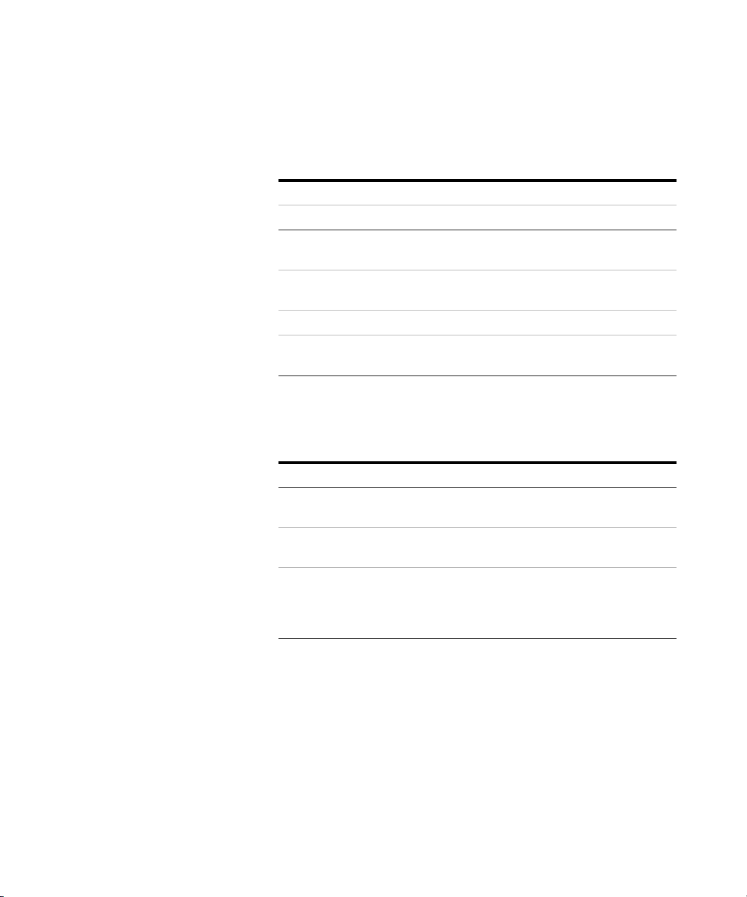
Tab l e 1 6000 Series Oscilloscopes Model Numbers and Sampling Rates
Bandwidth 100 MHz 300 MHz 500 MHz 1 GHz
Maximum Sample Rate 2 GSa/s 2 GSa/s 4 GSa/s 4 GSa/s
2-Channel + 16 Logic
Channels MSO
4-Channel + 16 Logic
Channels MSO
2-Channel DSO DSO6012A DSO6032A DSO6052A DSO6102A
4-Channel DSO DSO6014A,
MSO6012A MSO6032A MSO6052A MSO6102A
MSO6014A MSO6034A MSO6054A MSO6104A
DSO6014L
DSO6034A DSO6054A,
DSO6054L
DSO6104A,
DSO6104L
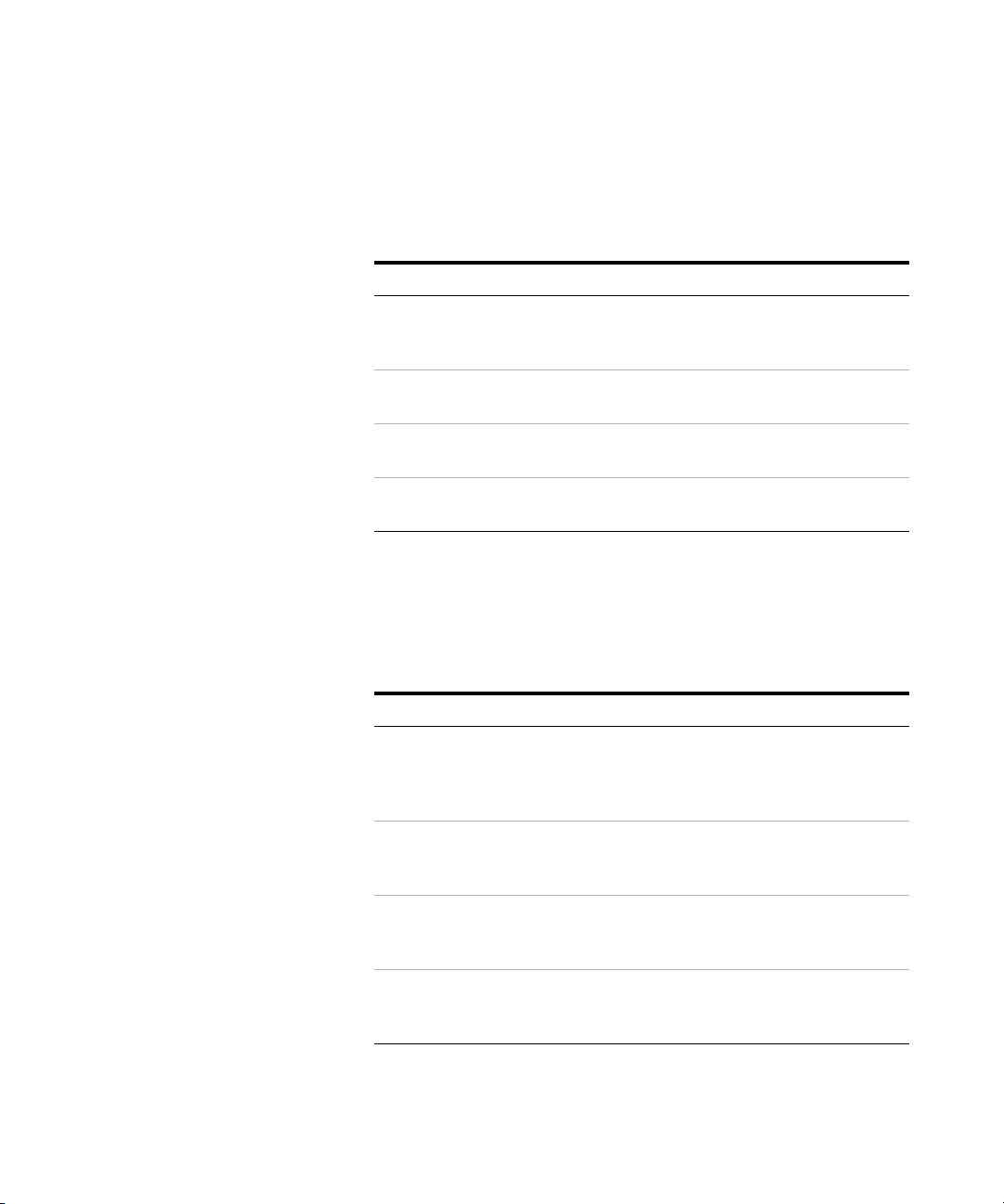
Tab l e 2 6000 Series Oscilloscopes Secure Environment Mode Option
Oscilloscope History Action
New order. No history. Order Option SEC. The Secure option
will be installed at the factory.
Previously purchased, no confidential
trace or user data has been stored.
Previously purchased, confidential
trace or user data has been stored.
Order N5427A. Return unit to Service
Center for Secure option installation.
Order N5427A. Replace acquisition
board. Destroy old acquisition board.
Return unit to Service Center for
Secure option installation.
6000 Series Oscilloscope User’s Guide 5
Page 6
Memory upgrades can be easily installed without returning the
oscilloscope to a Service Center. These upgrades are licensed.
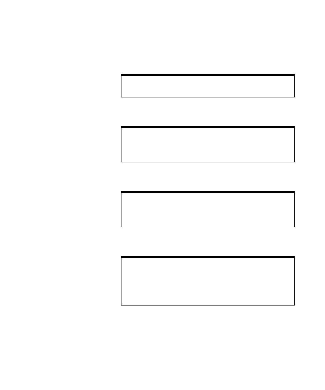
Tab l e 3 6000 Series Oscilloscopes Memory Depth Option Numbers
Maximum Memory Depth 1 Mpts 2 Mpts 8 Mpts
MSO/DSO6012A, MSO/DSO6014A,
MSO/DSO6032A, MSO/DSO6034A
oscilloscopes
MSO/DSO6052A, MSO/DSO6054A
oscilloscopes
MSO/DSO6102A, MSO/DSO6104A
oscilloscopes
DSO6014L, DSO6054L, DSO6104L
oscilloscopes
standard 2ML 8ML
standard 2MH 8MH
standard 2MH 8MH
n/a n/a standard
The following options can be easily installed without returning
the oscilloscope to a Service Center. These upgrades are
licensed.
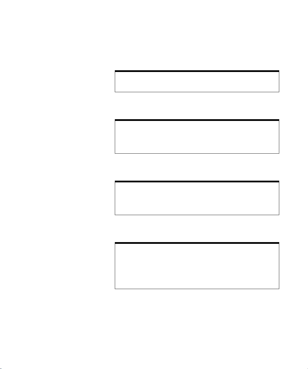
Tab l e 4 6000 Series Oscilloscopes Options
Licensed Option Order
Mixed Signal Oscilloscope (MSO) Order N2914A or N2915A (see data
sheet*). You can easily install this
option yourself. The logic cable kit is
supplied with the MSO license.
I2C/SPI serial decode option (for 4
channel or 4+16 channel models only)
Order N5423A after purchase (Option
LSS at time of purchase). You can
easily install this option yourself.
CAN/LIN automotive triggering and
decode (for 4 channel or 4+16 channel
models only)
N5406A FPGA dynamic probe N5406A with Option 001
Order N5424A after purchase (Option
AMS at time of purchase). You can
easily install this option yourself.
(Oscilloscope-locked license) or
Option 002 (PC-locked license).
6 6000 Series Oscilloscope User’s Guide
Page 7

*Visit www.agilent.com/find/mso6000 to view the 6000A Series and 6000L Series
data sheets.
6000 Series Oscilloscope User’s Guide 7
Page 8
Built-in Quick Help
A Quick Help system is built into the oscilloscope. Instructions for using the
quick help system are given on page 52.
Digital Channels
Because all of the oscilloscopes in the Agilent 6000 Series have analog channels,
the analog channel topics in this book apply to all instruments. Whenever a topic
discusses the digital channels, that information applies only to Mixed-Signal
Oscilloscope (MSO) models or DSO models that have been upgraded to an MSO.
Using this book with the 6000L Series oscilloscopes
The 6000L Series oscilloscopes do not have a built-in display or front panel
control keys. If you are using a 6000L Series oscilloscope, and this book refers to
using front panel controls, you can use the built-in Web control feature described
on page 39 to complete the instructions.
Abbreviated instructions for pressing a series of keys
Instructions for pressing a series of keys are written in an abbreviated manner.
Instructions for pressing Key1, then pressing Key2, then pressing Key3 are
abbreviated as follows:
Press Key1 & Key2 & Key3.
The keys may be front panel keys, or softkeys, which are located directly below
the oscilloscope display.
8 6000 Series Oscilloscope User’s Guide
Page 9

Contents
1 Getting Started 19
To inspect package contents 22
To adjust the 6000A Series handle 26
To mount the oscilloscope in a rack 27
To mount 6000A Series oscilloscopes in a rack 27
To mount the 6000L Series oscilloscopes in a rack 27
To power-on the oscilloscope 31
Ventilation requirements 31
The remote interface 33
To establish a LAN connection (6000A Series) 34
To establish a LAN connection (6000L Series) 35
To establish a point-to-point LAN connection 37
To use the Web interface 38
Controlling the oscilloscope using a Web browser 39
Setting a password 41
To connect the oscilloscope probes 46
To verify basic oscilloscope operation 47
To compensate the oscilloscope probes 48
To calibrate the probes 49
Passive Probes Supported 49
Active Probes Supported 50
By 300 MHz, 500 MHz, and 1 GHz Bandwidth Models 50
By 100 MHz Bandwidth Models 51
6000 Series Oscilloscope User’s Guide 9
Page 10

Contents
Using Quick Help 52
Quick Help Languages 53
2 Front-Panel Controls 55
6000L Series Oscilloscope Controls 56
Front and Rear Panel Controls and Connectors 57
6000A Series Oscilloscope Front-Panel Controls 60
Conventions 61
Graphic Symbols in Softkey Menus 61
4-Channel 6000A Series Oscilloscope Front Panel 62
Front Panel Controls 63
2-Channel 6000A Series Oscilloscope Front Panel (differences
only) 68
Interpreting the display 69
10 6000 Series Oscilloscope User’s Guide
Page 11

6000A Series Front-Panel Operation 70
To adjust the waveform intensity 70
To adjust the display grid (graticule) intensity 70
To start and stop an acquisition 71
To make a single acquisition 72
To pan and zoom 73
Choosing Auto trigger mode or Normal trigger mode 74
Using AutoScale 74
To set the probe attenuation factor 75
Using the analog channels 77
To set up the Horizontal time base 82
To make cursor measurements 89
To make automatic measurements 90
Using Labels 91
To print the display 95
To s et the cl oc k 95
To set up the screen saver 96
To set the waveform expansion reference point 97
To perform service functions 98
User Calibration 98
Self Test 101
About Oscilloscope 101
To restore the oscilloscope to its default configuration 102
Contents
3 Viewing and Measuring Digital Signals 105
To connect the digital probes to the circuit under test 106
Acquiring waveforms using the digital channels 109
To display digital channels using AutoScale 110
Example 110
Interpreting the digital waveform display 112
To switch all digital channels on or off 113
6000 Series Oscilloscope User’s Guide 11
Page 12

Contents
To switch groups of channels on or off 113
To switch a single channel on or off 113
To change the displayed size of the digital channels 114
To reposition a digital channel 114
To change the logic threshold for digital channels 115
To display digital channels as a bus 116
4 Triggering the Oscilloscope 121
Selecting Trigger Modes and Conditions 124
To select the Mode and Coupling menu 124
Trigger modes: Normal and Auto 125
To select trigger Coupling 127
To select trigger Noise Rejection and HF rejection 127
To set Holdoff 128
12 6000 Series Oscilloscope User’s Guide
The External Trigger input 130
2-Channel oscilloscope External Trigger input 130
4-Channel oscilloscope External Trigger input 132
Trig ge r Typ es 133
To use Edge triggering 134
Trigger level adjustment 135
To use Pulse Width triggering 136
< qualifier time set softkey 138
> qualifier time set softkey 138
To use Pattern triggering 139
To use CAN triggering 141
To use Duration triggering 145
< qualifier time set softkey 147
> qualifier time set softkey 147
Page 13

To use I2C triggering 148
To use Nth Edge Burst triggering 154
To use LIN triggering 156
To use Sequence triggering 159
Define the Find: stage 161
Define the Trigger on: stage 162
Define the optional Reset on: stage 164
Adjust the trigger level 165
To use SPI triggering 166
Assign source channels to the clock, data, and frame
signals 168
Set up the number of bits in the serial data string and set values
for those data bits 171
Resetting all bits in the serial data string to one value 171
To use TV triggering 171
Example exercises 175
To trigger on a specific line of video 175
To trigger on all sync pulses 177
To trigger on a specific field of the video signal 178
To trigger on all fields of the video signal 179
To trigger on odd or even fields 180
Contents
To use USB triggering 183
The Trigger Out connector 185
Tr ig g er s 185
Source frequency 185
Source frequency/8 185
5 Making Measurements 187
To use the XY horizontal mode 188
6000 Series Oscilloscope User’s Guide 13
Page 14

Contents
Math Functions 193
Math scale and offset 194
Multiply 195
Subtract 197
Differentiate 199
Integrate 201
FFT Measurement 203
FFT Operation 205
Cursor Measurements 210
To make cursor measurements 210
Cursor Examples 214
Automatic Measurements 217
To make an automatic measurement 218
To set measurement thresholds 219
Time Measurements 221
Delay and Phase Measurements 226
Voltage Measurements 228
Overshoot and Preshoot Measurements 234
6 Displaying Data 237
Pan and Zoom 238
To pan and zoom a waveform 238
To set the waveform expansion reference point 239
Antialiasing 240
Using the XGA video output 240
Display Settings 241
Infinite persistence 241
Grid intensity 242
Vectors (connect the dots) 242
Varying the intensity to view signal detail 243
14 6000 Series Oscilloscope User’s Guide
Page 15

Acquisition Modes 245
At Slower Sweep Speeds 245
Selecting the Acquisition mode 245
Normal Mode 246
Peak Detect Mode 246
High Resolution Mode 246
Averaging Mode 247
Realtime Sampling Option 249
Using Serial Decode 251
To d ec ode I
2
C data 252
To decode SPI data 256
To decode CAN data 261
CAN Totalizer 266
To decode LIN data 268
To reduce the random noise on a signal 274
HF Reject 274
LF Reject 275
Noise rejection 275
Contents
To capture glitches or narrow pulses with peak detect and infinite
persistence 276
Using peak detect mode to find a glitch 277
How AutoScale Works 279
Undo AutoScale 279
Specifying the Channels Displayed After AutoScale 280
Preserving the Acquisition Mode During AutoScale 280
7 Saving and Printing Data 281
To configure printing 282
Selecting a print file format 282
Selecting print options 285
Print Palette 285
6000 Series Oscilloscope User’s Guide 15
Page 16

Contents
To print the display to a file 286
To print the display to a USB printer 287
Supported printers 288
Printers 288
Secure Environment Mode Option 290
Saving and recalling traces and setups 292
To Autosave traces and setups 293
To save traces and setups to internal memory or to overwrite an
existing USB mass storage device file 294
To save traces and setups to a new file on the USB mass storage
device 295
To recall traces and setups 297
To use the file explorer 298
16 6000 Series Oscilloscope User’s Guide
8 Reference 301
Upgrading to an MSO or adding memory depth 302
Software and firmware updates 302
To set up the I/O port 303
Using the 10 MHz reference clock 304
Sample clock and frequency counter accuracy 304
Supplying an external timebase reference 304
To supply a sample clock to the oscilloscope 304
To synchronize the timebase of two or more instruments 306
To check warranty and extended services status 306
To return the instrument 307
To clean the oscilloscope 307
Page 17

Digital channel signal fidelity: Probe impedance and
grounding 308
Input Impedance 308
Probe Grounding 310
Best Probing Practices 312
To replace digital probe leads 313
Binary Data (.bin) 314
Binary Data in MATLAB 314
Binary Header Format 314
Example Program for Reading Binary Data 318
Examples of Binary Files 319
9 Characteristics and Specifications 321
6000A Series and 6000L Series Environmental Conditions 322
Overvoltage Category 322
Pollution Degree 322
Pollution Degree Definitions 322
Contents
6000A Series and 6000L Series Measurement Category 323
Measurement Category 323
Measurement Category Definitions 323
6000A Series and 6000L Series Transient Withstand
Capability 324
6000A Series Oscilloscope Specifications 325
6000A Series Oscilloscope Characteristics 326
6000L Series Specifications and Characteristics 336
Performance characteristics 336
Index 343
6000 Series Oscilloscope User’s Guide 17
Page 18

Contents
18 6000 Series Oscilloscope User’s Guide
Page 19

Agilent 6000 Series Oscilloscope
User’s Guide
1
Getting Started
To inspect package contents 22
To adjust the 6000A Series handle 26
To mount the oscilloscope in a rack 27
To power-on the oscilloscope 31
Ventilation requirements 31
The remote interface 33
To establish a LAN connection (6000A Series) 34
To establish a LAN connection (6000L Series) 35
To establish a point-to-point LAN connection 37
To use the Web interface 38
To connect the oscilloscope probes 46
To verify basic oscilloscope operation 47
To compensate the oscilloscope probes 48
To calibrate the probes 49
Passive Probes Supported 49
Active Probes Supported 50
Using Quick Help 52
To get started using the oscilloscope:
✔ Unpack the oscilloscope and verify the contents.
✔ Adjust the 6000A Series oscilloscope’s handle position.
✔ Apply power to the oscilloscope.
✔ Connect the probes to the oscilloscope.
Agilent Technologies
19
Page 20

1Getting Started
✔ Verify basic oscilloscope operation and compensate the
probes.
20 6000 Series Oscilloscope User’s Guide
Page 21
Getting Started 1
Built-in Quick Help
A Quick Help system is built into the oscilloscope. Instructions for using the
quick help system are given on page 52.
Digital Channels
Because all of the oscilloscopes in the Agilent 6000 Series have analog channels,
the analog channel topics in this book apply to all instruments. Whenever a topic
discusses the digital channels, that information applies only to Mixed-Signal
Oscilloscope (MSO) models or DSO models that have been upgraded to an MSO.
Using this book with the 6000L Series oscilloscopes
The 6000L Series oscilloscopes do not have a built-in display or front panel
control keys. If you are using a 6000L Series oscilloscope, and this book refers to
using front panel controls, you can use the built-in Web control feature described
on page 39 to complete the instructions.
Abbreviated instructions for pressing a series of keys
Instructions for pressing a series of keys are written in an abbreviated manner.
Instructions for pressing Key1, then pressing Key2, then pressing Key3 are
abbreviated as follows:
Press Key1 & Key2 & Key3.
The keys may be front panel keys, or softkeys, which are located directly below
the oscilloscope display.
6000 Series Oscilloscope User’s Guide 21
Page 22

1Getting Started
To inspect package contents
✔ Inspect the shipping container for damage.
If your shipping container appears to be damaged, keep the
shipping container or cushioning material until you have
inspected the contents of the shipment for completeness and
have checked the oscilloscope mechanically and electrically.
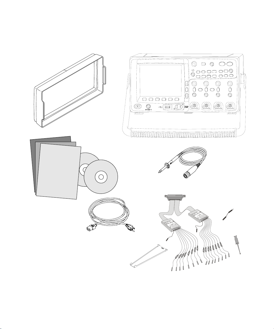
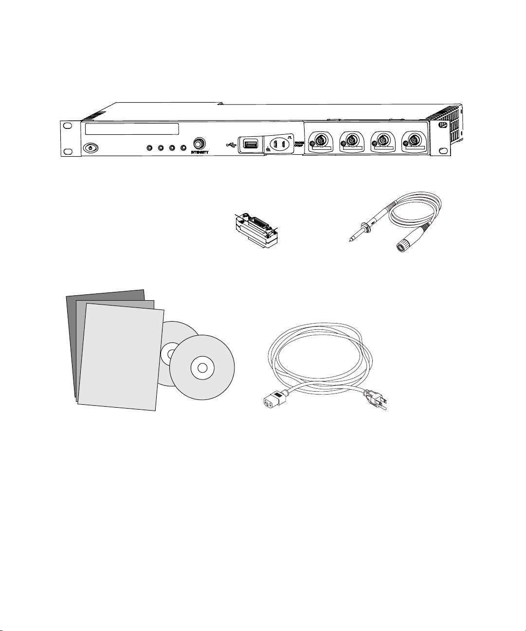
✔ Verify that you received the following items and any optional
accessories you may have ordered:
• 6000 Series Oscilloscope
• Front-panel cover (6000A Series only)
• Power cord (see Table 7 on page 32)
• LAN Crossover Cable 5061-0701 (6000L Series only)
• GPIB cable extender P/N 5183-0803 (6000L Series only)
• 50 ohm feedthrough termination adapter P/N 0960-0301
(Qty. 4 supplied with DSO6014L only)
• Oscilloscope probes
• Two probes for 2-channel models
• Four probes for 4-channel models
• 10074C probes for 100 MHz bandwidth models
• 10073C probes for all other models
• Manuals
• User’s Guide
• Service Guide
• Programmer’s Quick Start Guide
• CD-ROM containing the Programmer’s Reference Guide
• Automation-Ready Software CD-ROM
• MSO Models: digital probe kit (54620-68701) and digital
cable guide (54684-42301)
22 6000 Series Oscilloscope User’s Guide
Page 23
Getting Started 1
Front-panel cover
Manuals and
CD-ROMs
Power cord
(Part numbers given
on page 32)
*Digital Probe Kit contains:
54620-61801 16-channel cable (qty 1)
5959-9334 2-inch probe ground leads (qty 5)
5090-4833 Grabber (qty 20)
Digital probe replacement parts are listed on page 313
6000A Series
Oscilloscope
Oscilloscope probes
10073C or 10074C
(Qty 2 or 4)
Digital Probe Kit*
(MSO models only)
Digital
cable guide
(MSO models only)
Package contents for 6000A Series oscilloscopes
6000 Series Oscilloscope User’s Guide 23
Page 24
1Getting Started
50 ohm feedthrough
termination adapter
P/N 0960-0301, Qty. 4
6000L Series Oscilloscope
GPIB cable extender
P/N 5183-0803
Oscilloscope Probes
10073C or 10074C
Qty. 4
Manuals and
CD-ROMs
Power cord
(Part numbers given
on page 32)
Package contents for 6000L Series oscilloscopes
24 6000 Series Oscilloscope User’s Guide
Page 25

Getting Started 1
Tab l e 5 Accessories available
Model Description
N2918A 6000 Series Oscilloscope Evaluation Kit
1180CZ Testmobile oscilloscope cart (requires N2919A adapter kit)
N2919A Testmobile Adapter Kit
N2916A 6000A Rackmount Kit
54684-44101 Front-panel cover
N2605A-097 USB cable
10833A GPIB cable, 1 m long
10073C Passive probe, 10:1, 500 MHz, 1.5 m
10074C Passive probe, 10:1, 100 MHz, 1.5 m
54620-68701 Digital probe kit
54684-42301 Digital probe cable guide (cable tray)
0960-0301 50-Ohm Feedthrough
1130A InfiniiMax 1.5 GHz InfiniiMax differential probe amplifier
1141A InfiniiMax 200 MHz differential probe (with 1142A power supply)
1144A 800 MHz active probe (with 1142A power supply)
1145A 750 MHz 2-channel active probe (with 1142A power supply)
1156A 1.5 GHz active probe
01650-61607 16:16 logic cable and terminator (use with header on target sys.)
54620-68701 16:2 x 8 logic input probe assembly ( standard with MSO models)
1146A 100 kHz Current probe, AC/DC
10070C 1:1 Passive Probe
10072A Fine-pitch probe kit
10075A 0.5 mm IC clip kit
10076A 100:1, 4 kV 250 MHz probe
E2613B 0.5 mm Wedge probe adapter, 3-signal, qty 2
E2614A 0.5 mm Wedge probe adapter, 8-signal, qty 1
E2615B 0.65 mm Wedge probe adapter, 3-signal, qty 2
E2616A 0.65 mm Wedge probe adapter, 8-signal, qty 1
E2643A 0.5 mm Wedge probe adapter, 16-signal, qty 1
E2644A 0.65 mm Wedge probe adapter, 16-signal, qty 1
N2772A 20 MHz differential probe
N2773A Power supply for N2772A
N2774A 50 MHz current probe AC/DC
N2775A Power supply for N2774A
You can search for these parts at www.agilent.com or at www.parts.agilent.com.
6000 Series Oscilloscope User’s Guide 25
Page 26
1Getting Started
To adjust the 6000A Series handle
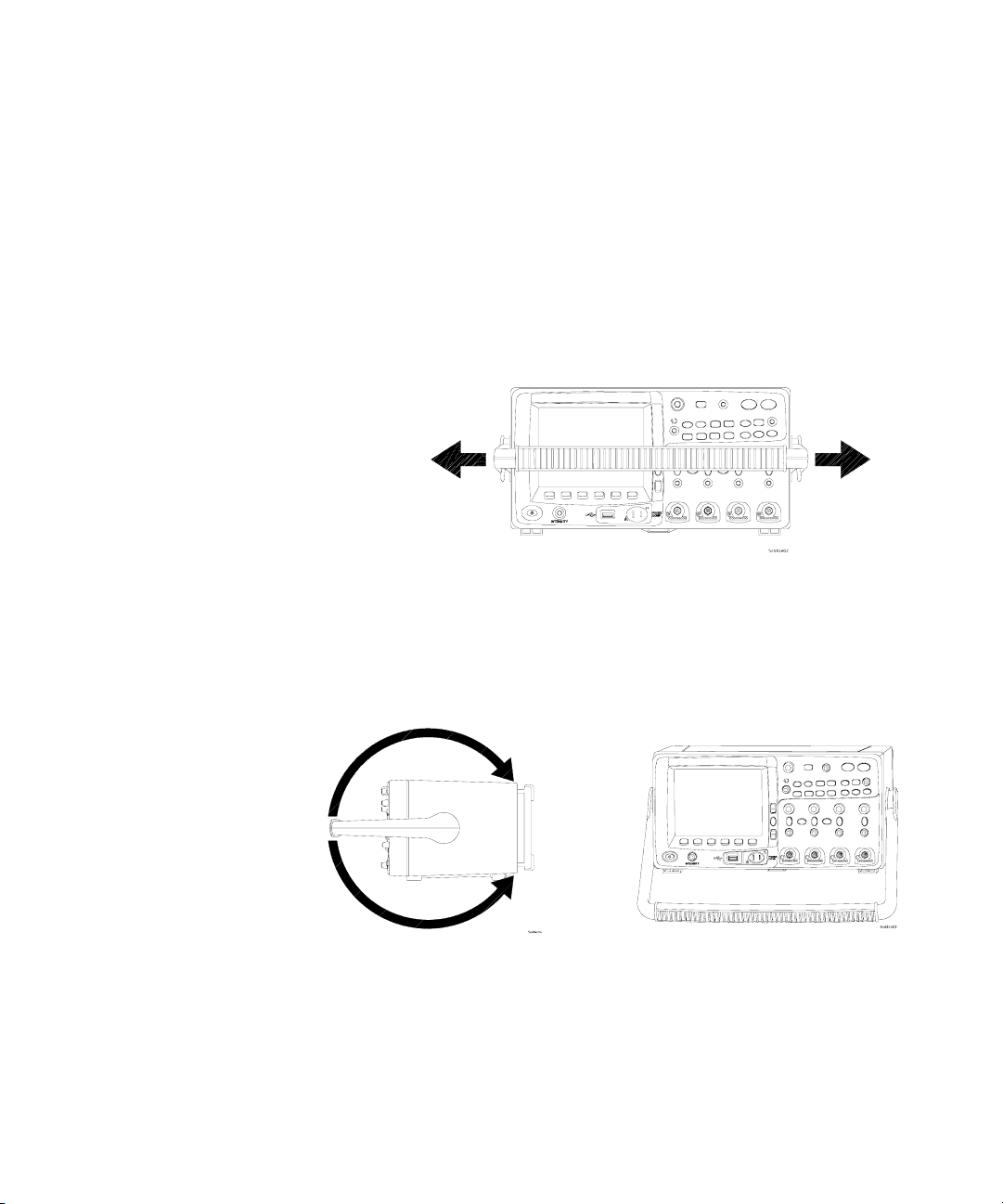
You can use the oscilloscope’s handle for carrying the
instrument, or you can use it as a stand to tilt the instrument up
for easier viewing of its display.
1 Grasp the handle hubs on each side of the instrument and
pull the hubs out until they stop.
26 6000 Series Oscilloscope User’s Guide
2 Without releasing the hubs, rotate the handle to the desired
position. Then release the hubs. Continue rotating the handle
until it clicks into a set position.
Page 27

To mount the oscilloscope in a rack
The 6000 Series oscilloscopes can be mounted into Electronic
Industries Association (EIA) standard 19-inch (487-mm) rack
cabinets.
To mount 6000A Series oscilloscopes in a rack
Purchase and install the N2916A rack mount kit. Instructions
are included in the kit.
To mount the 6000L Series oscilloscopes in a rack
The 6000L Series oscilloscope is supplied with all necessary
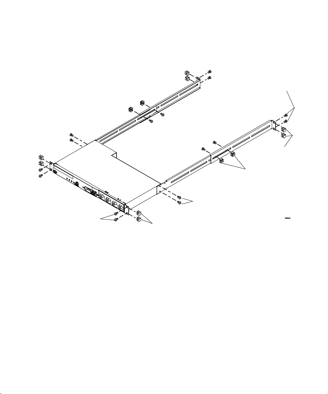
hardware for installation into a standard EIA 19-inch rack.
Tab l e 6 Rack Mount Hardware Supplied
Getting Started 1
Quantity Description Agilent Part
2 Front Extender Support D6104-01201
2 Rear Extender Support D6104-01202
4 Rear Extender Screw (M3 x 6 mm) 0515-0430
4 Dress Screw (10-32 x 0.0625) 0570-1577
8 Rail Screw (10-32 x 0.375) 2680-0281
12 Clip-nut (10-32) 0590-0804
Number
Tools required (not supplied)
• #2 Phillips screwdriver
• T20 Torx driver
• T10 Torx driver
6000 Series Oscilloscope User’s Guide 27
Page 28
1Getting Started
Step 4
If needed
Step 1,
step 5
Step 3
If needed
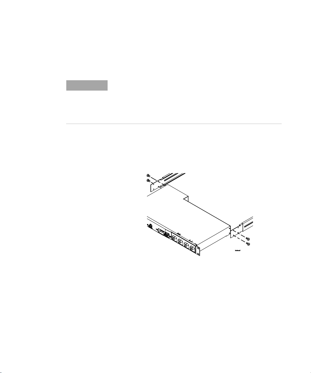
1 Loosely attach the Front Extender Supports to the Rear
Extender Supports with four (4) clip-nuts and four (4) of the
10-32 x 0.375 Rail Screws. (The screws require a Torx T20
driver.) Choose the correct set of slots in the supports such
that their overall length is approximately correct for the
depth of your cabinet.
28 6000 Series Oscilloscope User’s Guide
Step 2
Page 29
Getting Started 1
2 Fasten the Rack Mount Extenders to the oscilloscope chassis
with the four (4) M3 x 6 mm screws, using a Torx T10 driver
as follows:
NOTE
The sets of holes in the Rack Mount Extenders are slightly offset. This was
done to ensure that the Rack Mount Extenders are attached to the
oscilloscope at the correct points so that the oscilloscope’s ventilation
area is not obscured. The holes in the Rack Mount Extenders will align
with the correct holes in the oscilloscope and the screws will go in easily.
Do not force the screws into the wrong holes.
a Attach a Rack Mount Extender to the left side of the
oscilloscope using two (2) of the M3 x 6 mm screws in the
inner set of holes on the Rack Mount Extender.
Use inner
holes in
extender
Use outer
holes in
extender
b Attach the other Rack Mount Extender to the right side of
the oscilloscope using two (2) of the M3 x 6 mm screws in
the outer set of holes on the rack mount extender.
3 Place the instrument in the rack. Install the four (4)
10-32 x 0.625 Dress Screws in the chassis front ears to secure
the front of the instrument to the rack. Use the Phillips
screwdriver.
4 Align the ears in the Rear Mount Extenders with the correct
set of holes in the rear of the rack and secure the Rack Mount
6000 Series Oscilloscope User’s Guide 29
Page 30

1Getting Started
Extenders to the rack using the four (4) remaining
10-32 x 0.375 Rail Screws. Use the Torx T20 driver.
5 Securely attach the Rear Extender Supports to the Front
Extender Supports by tightening the four (4) 10-32 x 0.375
Rail Screws screws that you loosely attached in step 1.
30 6000 Series Oscilloscope User’s Guide
Page 31

To power-on the oscilloscope
1 Connect the power cord to the rear of the oscilloscope, then
to a suitable AC voltage source.
The oscilloscope automatically adjusts for input line voltages
in the range 100 to 240 VAC. Ensure that you have the correct
line cord. See Table 7 on page 32. The line cord provided is
matched to the country of origin.
Getting Started 1
WARNING
Ventilation requirements
Always use a grounded power cord. Do not defeat the power cord
ground.
2 Press the power switch.
The power switch is located on the lower left corner of the
front panel. Some front panel lights will come on and the
oscilloscope will be operational in a few seconds.
The air intake and exhaust areas must be free from
obstructions. Unrestricted air flow is required for proper
cooling.
6000A Ventilation Requirements
The fan draws air in from underneath the oscilloscope and
pushes it out behind the oscilloscope. Always ensure that the
air intake and exhaust areas are free from obstructions.
When using the oscilloscope in a bench-top setting, provide at
least 4" (100 mm) clearance behind and above the oscilloscope
for proper cooling.
6000L Ventilation Requirements
The fan draws air from the left and pushes it to the right.
Ensure that air flow is not obstructed.
6000 Series Oscilloscope User’s Guide 31
Page 32
1Getting Started
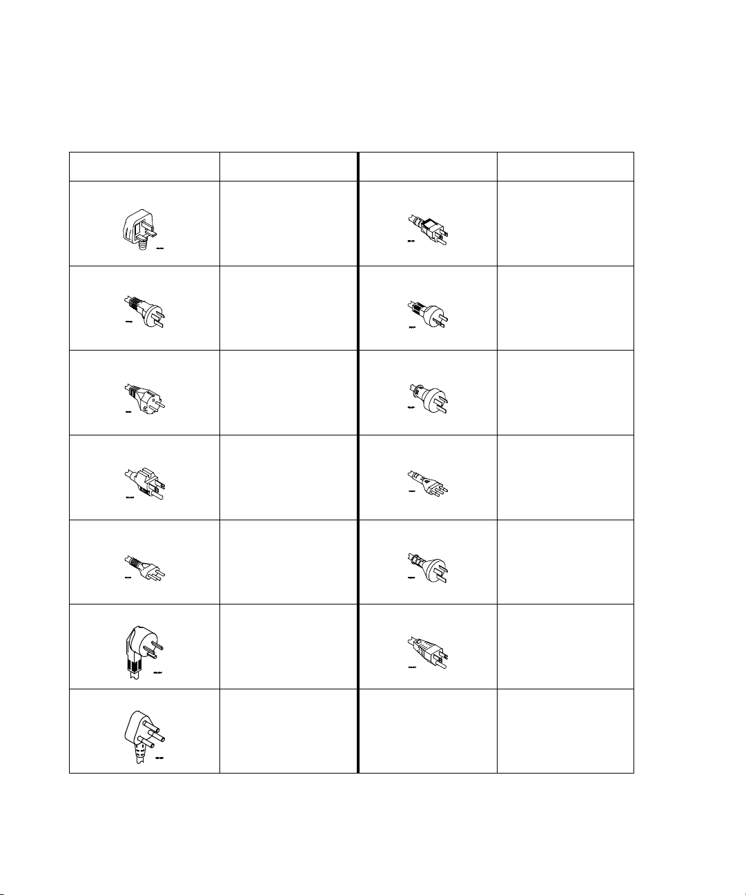
Tab l e 7 Power Cords
Plug Type Cable Part Number Plug Type Cable Part Number
Opt 900 (U.K.) 8120-1703 Opt 918 (Japan) 8120-4754
Opt 901 (Australia) 8120-0696 Opt 919 (Israel) 8120-6799
Opt 902 (Europe) 8120-1692 Opt 920 (Argentina) 8120-6871
Opt 903 (U.S.A.) 8120-1521 Opt 921 (Chile) 8120-6979
Opt 906 (Switzerland) 8120-2296 Opt 922 (China) 8120-8377
Opt 912 (Denmark) 8120-2957 Opt 927 (Thailand) 8120-8871
Opt 917 (South Africa) 8120-4600
32 6000 Series Oscilloscope User’s Guide
Page 33
The remote interface
Getting Started 1
You can communicate with all 6000 Series oscilloscopes via
LAN, USB, or GPIB. 6000A Series oscilloscopes can also be
controlled using the front panel keys. The 6000L Series
oscilloscopes do not have a keyboard or display, so
communication must be established via LAN, USB, or GPIB.
The Automation Ready CD-ROM provided with the oscilloscope
contains connectivity software to enable communication over
these interfaces. Refer to the instructions provided on the
CD-ROM to install this software on your PC.
Remote commands can be issued via LAN, USB, or GPIB. These
commands are generally used when the oscilloscope is under
program control for automated test and data acquisition.
Information about controlling the oscilloscope through remote
commands is contained in the 6000 Series Oscilloscopes
Programmer’s Quick Start Guide. To access this document
online, direct your web browser to
www.agilent.com/find/mso6000 and select Library.
All 6000 Series oscilloscopes feature a built-in Web server
(requires software version 4.0 or greater; see page 302 for
software updating instructions). Using the Web browser you can
set up measurements, monitor waveforms, capture screen
images and operate the oscilloscope remotely.
Detailed Connectivity Information
For detailed connectivity information, refer to the Agilent Technologies
USB/LAN/GPIB Connectivity Guide, which you can download from the
Agilent web site at the following URL:
www.agilent.com/find/connectivity.
6000 Series Oscilloscope User’s Guide 33
Page 34
1Getting Started
To establish a LAN connection (6000A Series)
1 If the controller PC isn’t already connected to the local area
network (LAN), do that first.
2 Get the oscilloscope’s network parameters (hostname,
domain, IP address, subnet mask, gateway IP, DNS IP, etc.)
from your network administrator.
3 Connect the oscilloscope to the local area network (LAN) by
inserting the LAN cable into the “LAN” port on the rear
panel of the oscilloscope.
4 On the oscilloscope, ensure the controller interface is
enabled:
a Press the Utility key.
b Using the softkeys, press I/O and Control.
c Use the Entry knob to select “LAN”; then, press the Control
softkey again.
5 Configure the oscilloscope’s LAN interface:
a Press the Configure softkey until “LAN” is selected.
b Press the LAN Settings softkey.
c Press the Addresses softkey. Use the IP Options softkey and
the Entry knob to select DHCP, AutoIP, or netBIOS. Use
the Modify softkey (and the other softkeys and the Entry
knob) to enter the IP Address, Subnet Mask, Gateway IP,
and DNS IP values. When you are done, press the return
(up arrow) softkey.
d Press the Domain softkey. Use the Modify softkey (and the
other softkeys and the Entry knob) to enter the Host name
and the Domain name. When you are done, press the
return (up arrow) softkey.
NOTE
34 6000 Series Oscilloscope User’s Guide
When you connect the oscilloscope to a LAN it is a good practice to limit
access to the oscilloscope by setting a password. By default, the
oscilloscope is not password protected. See page 41 to set a password.
Page 35
To establish a LAN connection (6000L Series)
1 Connect a cable from your site Local Area Network (LAN) to
the LAN port on the rear panel of the oscilloscope.
2 Switch on the oscilloscope power. When the LAN indicator
illuminates green, the LAN is connected as configured. This
may take a few minutes. The oscilloscope will attempt to
connect to the LAN using DHCP, AutoIP, then Manual, in that
order (when enabled). These connection methods can be
enabled or disabled using the Config softkey in the LAN
Settings Menu.
3 Open a web browser and enter the oscilloscope’s hostname in
the address field. The oscilloscope’s Web page will be
displayed.
Hostname
If you do not know the oscilloscope’s hostname you can reset
the hostname as follows:
1 Press and release the Reset button (see page 56, 57) on the
front panel of the 6000L Series oscilloscope. This will reset
the hostname to that which is printed on the label near the
oscilloscope’s power cord connection. The following LAN
parameters will be reset:
• Hostname
• IP address
• Domain name
• VISA address
• Password (see page 41.)
Getting Started 1
NOTE
6000 Series Oscilloscope User’s Guide 35
When you connect the oscilloscope to a LAN it is a good practice to limit
access to the oscilloscope by setting a password. By default, the
oscilloscope is not password protected. See page 41 to set a password.
Page 36
1Getting Started
NOTE
Any time you modify the oscilloscope’s hostname it will break the
connection between the oscilloscope and the LAN. You will need to
re-establish communication to the oscilloscope using the new hostname.
For more information about connecting to the oscilloscope,
refer to the Agilent Technologies Connectivity Guide for Agilent
USB, LAN, and GPIB interfaces. A printable electronic copy of
the Connectivity Guide can be found at
www.agilent.com/find/connectivity.
36 6000 Series Oscilloscope User’s Guide
Page 37

To establish a point-to-point LAN connection
Stand-alone connection to a PC
The following procedure describes how to establish a
point-to-point (stand alone) connection to the oscilloscope. This
is useful if you want to control the oscilloscope using a laptop
computer or a stand-alone computer.
1 Install Agilent I/O Libraries Suite from the CD that was
supplied with the oscilloscope. If you do not have the CD you
can download the I/O Libraries Suite from
www.agilent.com/find/iolib.
2 Connect your PC to the oscilloscope using a cross-over LAN
cable. (The 5061-0701 LAN crossover cable is supplied with
6000L Series oscilloscopes.)
3 Switch on the oscilloscope power. When the LAN indicator
illuminates green, the LAN is connected as configured. This
may take a few minutes.
4 Start the Agilent Connection Expert application from the
Agilent I/O Libraries Suite program group.
5 When the Agilent Connection Expert application is
displayed, select Refresh All.
6 Right Click LAN and select Add Instrument.
7 In the Add Instrument window, the LAN line should be
highlighted; select OK.
8 In the LAN Instrument window, select Find Instruments…
9 In the Search for instruments on the LAN window, LAN and
Look up hostnames should be checked.
10 Select the Find Now key. (NOTE: It may take up to three
minutes before the instrument is found. If the instrument is
not found the first time, wait about one minute and try
again.)
11 When the instrument is found, select OK and OK to close the
Add Instrument windows.
Getting Started 1
Now the instrument is connected and the instrument’s Web
interface may be used.
6000 Series Oscilloscope User’s Guide 37
Page 38

1Getting Started
To use the Web interface
All 6000 Series oscilloscopes include a built-in Web server
(requires software version 4.0 and above). See page 302 for
information about updating your oscilloscope’s software.
When you connect to the oscilloscope using a computer and web
browser, you can:
• Control the oscilloscope using the Remote Front Panel
function.
• Activate the Identify function (see page 44) to identify a
particular instrument by causing it’s front panel light to
blink.
• View information about the oscilloscope like its model
number, serial number, host name, IP address, and VISA
connect string.
• View oscilloscope firmware version information and upload
new firmware into the oscilloscope.
• View and modify the oscilloscope’s network configuration
and status information.
38 6000 Series Oscilloscope User’s Guide
Page 39
Controlling the oscilloscope using a Web browser
Getting Started 1
A built-in Web server allows communication and control via a
Java™-enabled Web browser. Measurements can be set up,
waveforms can be monitored, screen images can be captured,
and the oscilloscope can be operated remotely. Also, SCPI
(Standard Commands for Programmable Instrumentation)
commands can be sent over the LAN.
Microsoft Internet Explorer 6 is the recommended Web browser
for communication and control of the oscilloscope. Other Web
browsers may work but are not guaranteed to work with the
oscilloscope. The Web browser must be Java-enabled with Sun
Microsystems™ Java Plug-in.
Operating the oscilloscope using a Web browser
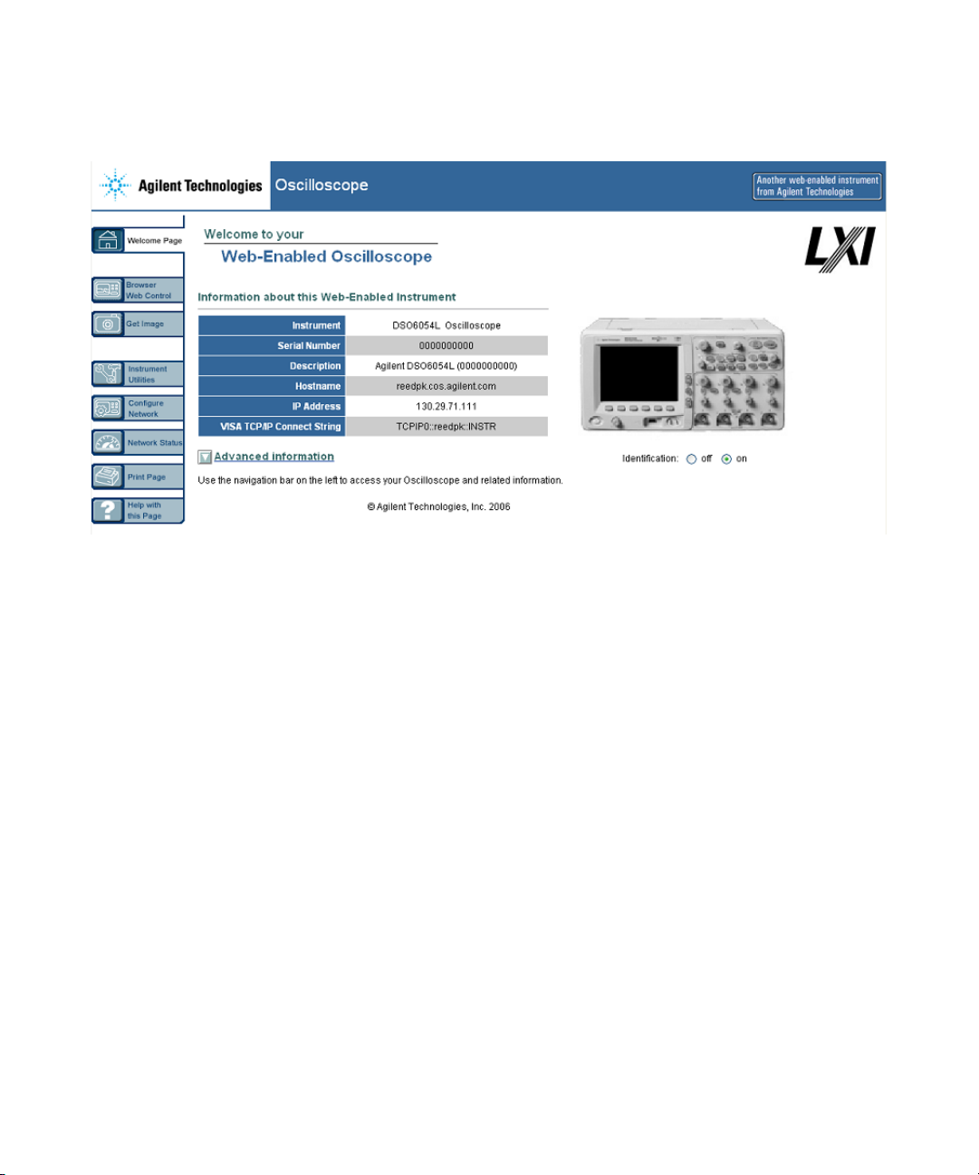
1 Connect the oscilloscope to your LAN (see page 34 or 35), or
establish a point-to-point connection (see page 37). It is
6000 Series Oscilloscope User’s Guide 39
Page 40
1Getting Started
possible to use a point-to-point connection (see page 37), but
using a LAN is the preferred method.
2 When the oscilloscope’s Web page is displayed, select
Browser Web Control, then select Remote Front Panel. After a few
seconds the Remote Front Panel appears.
NOTE
If Java is not installed on your PC, you will be prompted to install the
Sun Microsystems Java Plug-in. This plug-in must be installed on the
controlling PC for Remote Front Panel operation.
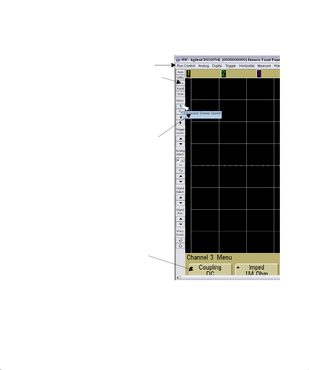
3 Use the Main Menu and the Function Keys to control the
oscilloscope. This is a manual way to control an oscilloscope
which is normally controlled by a remote program.
40 6000 Series Oscilloscope User’s Guide
Page 41
Step 1
Getting Started 1
Setting a password
Whenever you connect the oscilloscope to a LAN, it is good
practice to set a password to prevent unauthorized access to the
oscilloscope via Web browser.
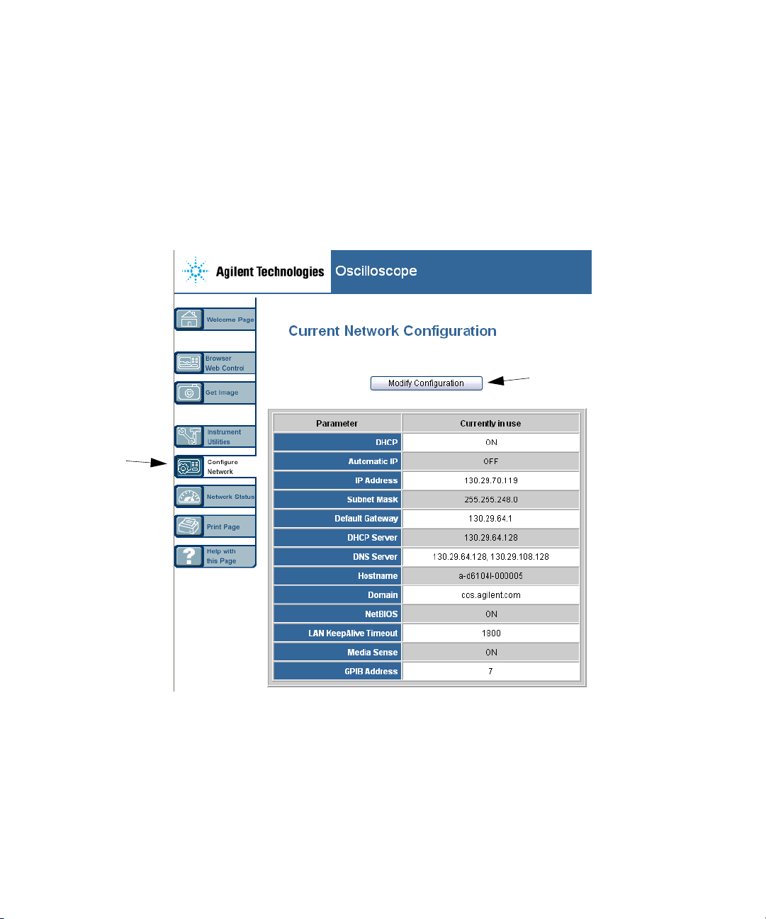
1 Select the Configure Network tab from the instrument’s
Wel come page.
Step 2
6000 Series Oscilloscope User’s Guide 41
Page 42
1Getting Started
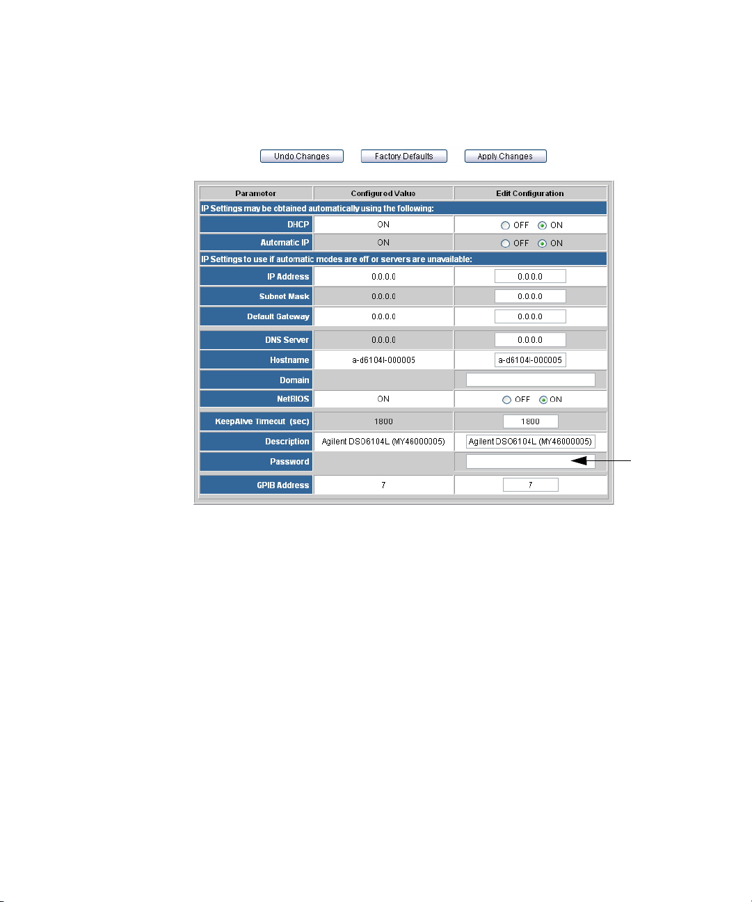
2 Select the Modify Configuration button.
3 Enter your desired password.
4 To reset the password:
• 6000A Series oscilloscopes - Press Utility & I/O & LAN Reset.
• 6000L Series oscilloscopes - Press the
the front panel.
42 6000 Series Oscilloscope User’s Guide
LAN RESET button on
Step 3
Page 43
Main Menu
Function Keys
Hint appears
when you
roll over with
mouse
Getting Started 1
Softkeys
(Left-click to
select, Rightclick for
Quick Help
6000 Series Oscilloscope User’s Guide 43
Page 44
1Getting Started
Scrolling and Monitor Resolution
When using a monitor resolution of 1024 x 768 or less on the
remote computer, you need to scroll to access the full remote
front panel. To display the remote front panel without scroll
bars, use a monitor resolution greater than 1024 x 768 on your
computer’s display.
Identify Function
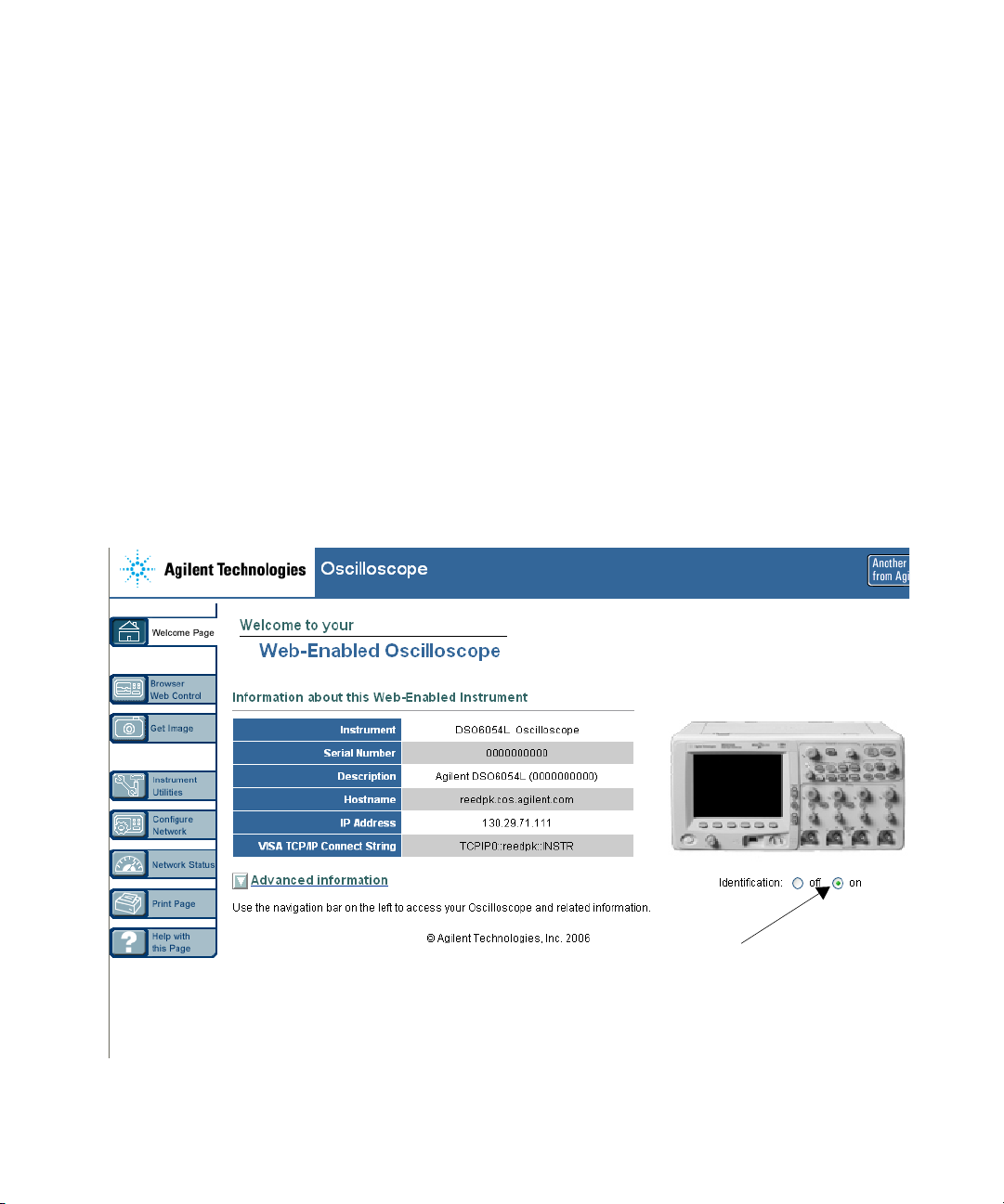
Select the Identify On button (located below the picture of the
oscilloscope) on the oscilloscope’s web page. The LAN indicator
on the front of the 6000L Series oscilloscope will flash green to
identify the oscilloscope until you switch Identify off. On the
6000A Series oscilloscope, an “Identify” message will be
displayed and you will need to press a Softkey to continue. This
feature is useful when trying to locate a specific instrument in a
rack of equipment.
Identify Button
44 6000 Series Oscilloscope User’s Guide
Page 45

Getting Started 1
For more information about connecting the oscilloscope to a
LAN see the Agilent Technologies Connectivity Guide for
Agilent USB, LAN, and GPIB interfaces. For a printable
electronic copy of the Connectivity Guide direct your Web
browser to www.agilent.com and search for Connectivity Guide.
6000 Series Oscilloscope User’s Guide 45
Page 46
1Getting Started
To connect the oscilloscope probes
The analog input impedance of the 100 MHz oscilloscopes is
fixed at 1 MΩ. The 1 MΩ mode is for use with many passive
probes and for general purpose measurements. The high
impedance minimizes the loading effect of the oscilloscope on
the circuit under test. If a 50 Ω input impedance is required,
attach a 50 ohm feedthrough termination adapter such as
Agilent part number 0960-0301 to the oscilloscope’s channel
input BNC connector.
The analog input impedance of the 300 MHz, 500 MHz, and
1 GHz oscilloscopes can be set to either 50 Ω or 1 MΩ. The 50 Ω
mode matches 50 Ω cables and some active probes commonly
used in making high frequency measurements. This impedance
matching gives you the most accurate measurements since
reflections are minimized along the signal path.
1 Connect the supplied oscilloscope probe to an oscilloscope
channel BNC connector on the front panel of the
oscilloscope.
2 Connect the retractable hook tip on the probe tip to the
circuit point of interest. Be sure to connect the probe ground
lead to a ground point on the circuit.
CAUTION
CAUTION
46 6000 Series Oscilloscope User’s Guide
Do not exceed 5 Vrms at the BNC in 50 Ω mode on the Agilent 6000
Series oscilloscopes. Input protection is enabled in 50 Ω mode and the
50 Ω load will disconnect if greater than 5 Vrms is detected. However
the inputs could still be damaged, depending on the time constant of
the signal. The 50 Ω input protection mode on the Agilent 6000 Series
oscilloscopes only functions when the oscilloscope is powered on.
The probe ground lead is connected to the oscilloscope chassis and
the ground wire in the power cord. If you need to measure between
two live points, use a differential probe. Do not negate the protective
action of the ground connection to the oscilloscope. The oscilloscope
must remain grounded through its power cord.
Page 47
Getting Started 1
CAUTION
Maximum input voltage for analog inputs:
CAT I 300 Vrms, 400 Vpk; transient overvoltage 1.6 kVpk
CAT II 100 Vrms, 400 Vpk
with 10073C or 10074C 10:1 probe: CAT I 500 Vpk, CAT II 400 Vpk
To verify basic oscilloscope operation
If you have a 6000L Series oscilloscope, you will need to start a
Web control session, as described on page 39.
1 Press the Save/Recall key on the front panel, then press the
Default Setup softkey. (The softkeys are located directly below
the display on the front panel.) The oscilloscope is now
configured to its default settings.
2 Connect an oscilloscope probe from channel 1 to the Probe
Comp signal terminal on the front panel.
3 Connect the probe’s ground lead to the ground terminal that
is next to the Probe Comp terminal.
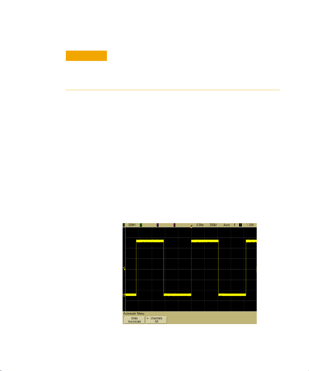
4 Press AutoScale.
5 You should see a waveform on the oscilloscope’s display
similar to this:
6000 Series Oscilloscope User’s Guide 47
Page 48

1Getting Started
r
If you see the waveform, but the square wave is not shaped
correctly as shown above, perform the procedure “To
compensate the oscilloscope probes” on page 48.
If you do not see the waveform, ensure your power source is
adequate, the oscilloscope is properly powered-on, and the
probe is connected securely to the front-panel oscilloscope
channel input BNC and to the Probe Comp terminal.
To compensate the oscilloscope probes
You should compensate your oscilloscope probes to match their
characteristics to the oscilloscope’s channels. A poorly
compensated probe can introduce measurement errors.
1 Perform the procedure “To verify basic oscilloscope
operation” on page 47.
2 Use a nonmetallic tool to adjust the trimmer capacitor on the
probe for the flattest pulse possible. The trimmer capacitor is
located on the probe BNC connector.
Perfectly compensated
Over compensated
Under compensated
comp.cd
3 Connect probes to all other oscilloscope channels (channel 2
of a 2-channel oscilloscope, or channels 2, 3, and 4 of a
4-channel oscilloscope). Repeat the procedure for each
channel. This matches each probe to each channel.
The process of compensating the probes serves as a basic test to
verify that the oscilloscope is functional.
48 6000 Series Oscilloscope User’s Guide
Page 49
To calibrate the probes
Getting Started 1
The oscilloscope can accurately calibrate its analog oscilloscope
channels to certain active probes, such as InfiniiMax probes.
Other probes, such as the 10073C and 10074C passive probes,
do not require calibration. The Calibrate Probe softkey will be
grayed-out (displayed in faint text) when a connected probe
does not require calibration.
When you connect a probe that can be calibrated (such as an
InfiniiMax probe), the Calibrate Probe softkey in the channel’s
menu will become active. Connect the probe to the Probe Comp
terminal, and the probe ground to the Probe Comp ground
terminal. Press the Calibrate Probe softkey and follow the
instructions on the display.
NOTE
Passive Probes Supported
When calibrating a differential probe, connect the positive lead to the
Probe Comp terminal and the negative lead to the Probe Comp ground
terminal. You may need to connect an alligator clip to the ground lug to
allow a differential probe to span between the Probe Comp test point and
ground. A good ground connection ensures the most accurate probe
calibration.
The following passive probes can be used with the 6000 Series
oscilloscopes. Any combination of passive probes can be used.
Tab l e 8 Passive Probes
Passive Probes Quantity Supported
10070C 4
10073C 4
10074C 4
10076A 4
6000 Series Oscilloscope User’s Guide 49
Page 50

1Getting Started
Active Probes Supported
By 300 MHz, 500 MHz, and 1 GHz Bandwidth Models
Active probes that do not have their own external power supply
require substantial power from the AutoProbe interface. (The
AutoProbe interface is present on the 300 MHz, 500 MHz, and
1 GHz bandwidth models.) “Quantity Supported” indicates the
maximum number of each type of active probe that can be
connected to the oscilloscope. If too much current is drawn
from the AutoProbe interface, an error message will be
displayed, indicating that you must momentarily disconnect all
probes to reset the AutoProbe interface.
Tab l e 9 Active Probes for 300 MHz, 500 MHz, and 1 GHz bandwidth
models
Active Probes Quantity Supported
1130A 2
1131A 2
1132A 2
1134A 2
1141A with 1142A power supply 4
1144A with 1142A power supply 4
1145A with 1142A power supply 2
1147A 2
1156A 4
1157A 4
1158A 4
N2772A with N2773A power supply 4
N2774A with N2775A power supply 4
50 6000 Series Oscilloscope User’s Guide
Page 51

By 100 MHz Bandwidth Models
The following active probes use their own power supply.
Therefore, they can be used on all 6000 Series oscilloscopes,
including the 100 MHz bandwidth models.
Many active probes have a 50 Ω output impedance. The input
impedance of 6000 Series 100 MHz bandwidth models is fixed at
1MΩ. When connecting these probes to 6000 Series 100 MHz
bandwidth models, a 50 Ω feedthrough terminator (such as
Agilent part number 0960-0301 is required).
Tab l e 1 0 Active Probes for All 6000 Series Oscilloscopes
Active Probes Quantity Supported
1141A with 1142A power supply 4
1144A with 1142A power supply 4
1145A with 1142A power supply 2
N2772A with N2773A power supply 4
Getting Started 1
N2774A with N2775A power supply 4
6000 Series Oscilloscope User’s Guide 51
Page 52
1Getting Started
Using Quick Help
To view Quick Help on 6000L Series oscilloscopes:
Start a Web browser control session as described on page 39
and select Remote Front Panel. To view Quick Help information,
right-click on the softkey. Help is not available for front panel
keys; only softkeys.
To view Quick Help on 6000A Series oscilloscopes
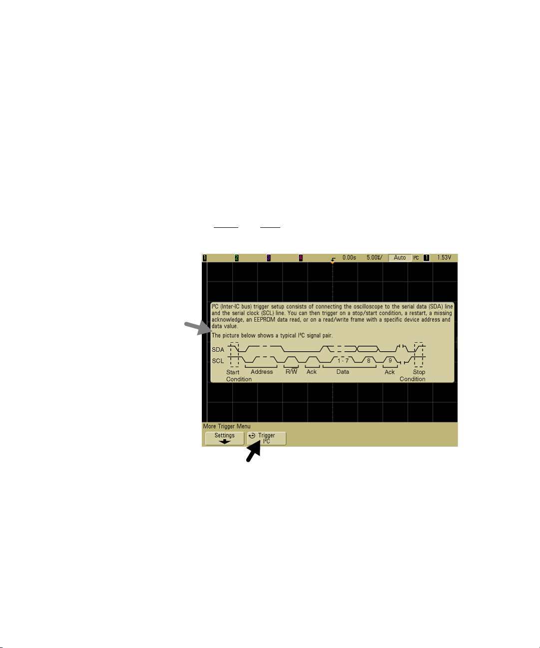
1 Press and hold down the key or softkey for which you would
like to view help.
Quick Help Message
Press and Hold 6000A Front Panel Key or Softkey
or Right-Click Softkey when using Web browser control
You can set Quick Help to close when you release the key (this is
the default mode) or to remain on the screen until another key
is pressed or a knob is turned. To select this mode, press the
Utility key, then press the Language softkey, then press the Help
Remain/Help Close softkey.
52 6000 Series Oscilloscope User’s Guide
Page 53

Quick Help Languages
At the time this manual was published, Quick Help was
available in English, Simplified Chinese, Japanese, German,
French, and Russian.
To choose a Quick Help language in the oscilloscope:
1 Press Utility, then press the Language softkey.
2 Repeatedly press and release the next Language softkey until
the desired language is selected.
If Quick Help updates become available, you can download the
updated Quick Help language file and load it into the
oscilloscope.
To download the 6000 Series Oscilloscope Quick Help Language
Support file:
1 Direct your web browser to www.agilent.com/find/mso6000.
2 On the resulting page, select Technical Support, then select
Software Downloads & Utilities.
Getting Started 1
6000 Series Oscilloscope User’s Guide 53
Page 54

1Getting Started
54 6000 Series Oscilloscope User’s Guide
Page 55

Agilent 6000 Series Oscilloscope
User’s Guide
2
Front-Panel Controls
6000L Series Oscilloscope Controls 56
6000A Series Oscilloscope Front-Panel Controls 60
6000A Series Front-Panel Operation 70
Agilent Technologies
55
Page 56
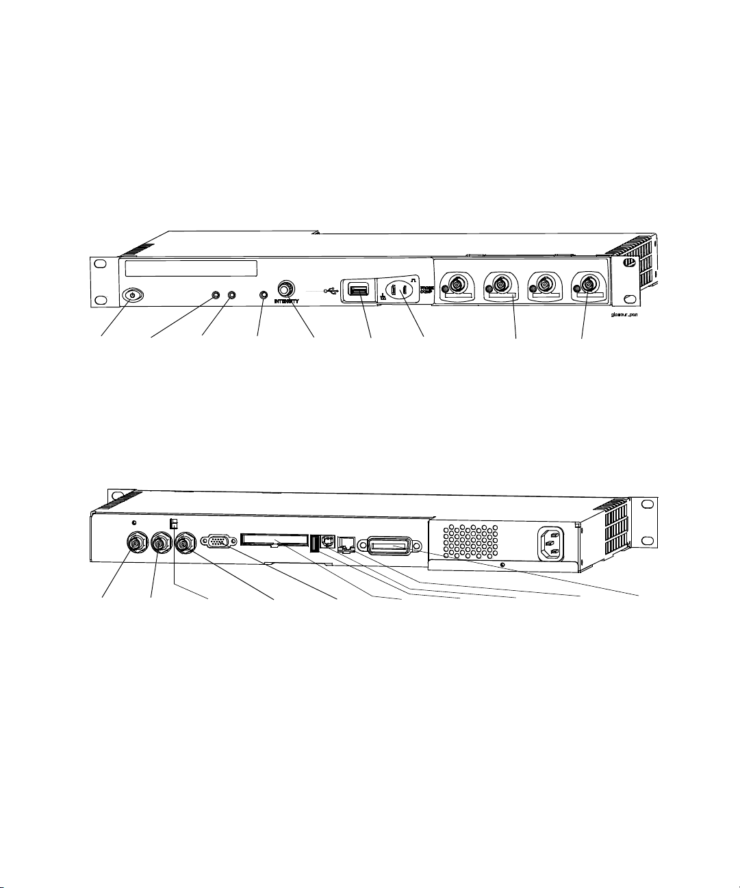
2 Front-Panel Controls
6000L Series Oscilloscope Controls
The 6000L Series oscilloscope is designed to be remotely
controlled. Therefore the front panel layout is simple.
Front Panel
1
Power
Switch
10
External
Trigger
Input
2
Power
Indicator
11
Trigger
Output
3
LAN
Status
Indicator
12
Calibration
Protect
Switch
4
Reset
Switch
13
10 MHz
Reference
Output
5
Intensity
Control
Rear Panel
XGA Video
Output
14
6
USB
Port
Channels
Terminals
15
Digital
Input
7
Probe
Comp
16
USB Host
Port
8
AutoProbe
Interface
17
USB
Device
Port
9
Channel
Inputs
18
LAN
Connector
19
GPIB
Connector
56 6000 Series Oscilloscope User’s Guide
Page 57

Front and Rear Panel Controls and Connectors
1. Power Switch Press once to switch power on; press again to
switch power off. See page 31.
2. Power Indicator Illuminates green when power is on.
3. LAN Status Indicator This indicator illuminates green when a
LAN connection has been detected and is connected as
configured. The LAN status indicator illuminates red when the
following LAN faults occur:
• failure to acquire a valid IP address
• detection of a duplicate IP address
• failure to renew an already acquired DHCP lease
The LAN status indicator flashes green when the identify
function is activated (see page 44).
4. Reset Switch When power is on, press and release this
recessed pushbutton to default LAN parameters. See page 35.
Front-Panel Controls 2
5. Intensity Control Rotate clockwise to increase analog
waveform intensity; counterclockwise to decrease. You can vary
the intensity control to bring out signal detail, much like an
analog oscilloscope. Digital channel waveform intensity is not
adjustable. More details about using the Intensity control to
view signal detail are on page 243.
6. USB Host Port Connect a USB compliant mass storage device
to store or recall oscilloscope setup files or waveforms. You can
also use the USB port to update the oscilloscope’s system
software or Quick Help language files if updates are available.
You do not need to take special precautions before removing the
USB mass storage device from the oscilloscope (you do not need
to “eject” it). Simply unplug the USB mass storage device from
the oscilloscope when the file operation is complete. More
information on using the USB port is given in Chapter 7, “Saving
and Printing Data,” starting on page 281.
6000 Series Oscilloscope User’s Guide 57
Page 58

2 Front-Panel Controls
CAUTION
Only connect USB devices to the USB host port. Do not attempt to
connect a host computer to this port to control the oscilloscope. Use
the USB device port if you want to connect a host (see the 6000 Series
Oscilloscope Programmer’s Quick Start Guide for details).
7. Probe Compensation Terminals Use the signal at these
terminals to match each probe’s characteristics to the
oscilloscope channel to which it is connected. See page 48.
8. AutoProbe Interface (Not available on 100 MHz bandwidth
models.) When you connect a probe to the oscilloscope, the
AutoProbe Interface attempts to determine the type of probe
and set its parameters in the Probe menu accordingly. See
page 75. Note: Although the 100 MHz models lack the AutoProbe
interface, they do have a probe sense ring around the BNC.
Therefore, the probe attenuation factor will be automatically set
when you connect a compatible probe such as the 10073C or
10074C.
9. Channel Input BNC Connector Attach the oscilloscope probe
or BNC cable to the BNC connector. This is the channel’s input
connector.
10. External Trigger Input Allows you to trigger the oscilloscope
using an external signal. See page 130.
11. Trigger Output This output is related to the oscilloscope’s
internal trigger signal. See page 185.
12. Calibration Protect Switch Set this switch to “Protect” to
prevent unwanted re-calibration. See page 98.
13. 10 MHz Reference Input/Output You can input a signal,
synchronizing multiple instruments, or you can output this
instrument’s reference signal. See page 304.
14. XGA Video Output You can connect an external display to
the oscilloscope for viewing waveforms. See page 240.
58 6000 Series Oscilloscope User’s Guide
Page 59

Front-Panel Controls 2
15. Digital Channels Input If you purchased the MSO upgrade
you can view and trigger on digital signals. See page 105.
16. USB Host Port Connect a USB compliant mass storage
device to store or recall oscilloscope setup files or waveforms.
You can also use the USB port to update the oscilloscope’s
system software or Quick Help language files if updates are
available. You do not need to take special precautions before
removing the USB mass storage device from the oscilloscope
(you do not need to “eject” it). Simply unplug the USB mass
storage device from the oscilloscope when the file operation is
complete. More information on using the USB port is given in
Chapter 7, “Saving and Printing Data,” starting on page 281.
CAUTION
Only connect USB devices to the USB host port. Do not attempt to
connect a host computer to this port to control the oscilloscope. Use
the USB device port if you want to connect a host (see the 6000 Series
Oscilloscope Programmer’s Quick Start Guide for details).
17. USB Device Port You can use this port for remote control of
the oscilloscope by connecting to a PC host computer. See the
6000 Series Oscilloscope Programmer’s Quick Start Guide for
details.
18. LAN Connector You can use this port to connect to the
oscilloscope and control it via your LAN. This standard LAN
port is not Auto-MDIX compliant. See page 34 or page 35.
19. GPIB Connector This connector is for connecting the
oscilloscope to a General Purpose Interface Bus. See the 6000
Series Oscilloscope Programmer’s Quick Start Guide for
details.
6000 Series Oscilloscope User’s Guide 59
Page 60
2 Front-Panel Controls
6000A Series Oscilloscope Front-Panel Controls
This is an introduction to the front-panel controls of the Agilent
6000A Series oscilloscope. Generally, you set up the front-panel
controls and then make a measurement.
The keys on the front panel bring up softkey menus on the
display that provide access to oscilloscope features. Many
softkeys use the Entry knob to select values.
Six softkeys are located below the display. To understand the
symbols used in the softkey menus and throughout this guide,
see “Conventions” on page 61.
Note that the Digital Select key, not the Entry knob, is used to
select digital channels when you want to reposition a digital
channel waveform.
NOTE
The simplest way to set up the oscilloscope is to connect it to the signals
of interest and press the AutoScale key.
60 6000 Series Oscilloscope User’s Guide
Page 61
Conventions
Throughout this book, the front-panel keys and softkeys are
denoted by a change in font. For example, the Cursors key is in
the Measure section of the front panel. The Acq Mode softkey is
the left-most softkey when the Acquire menu is displayed.
In this manual, instructions for pressing a series of keys are
written in an abbreviated manner. Pressing the Utility key, then
the I/O softkey, then the Show I/O Config softkey is abbreviated
as follows:
Press Utility & I/O & Show I/O Config.
Graphic Symbols in Softkey Menus
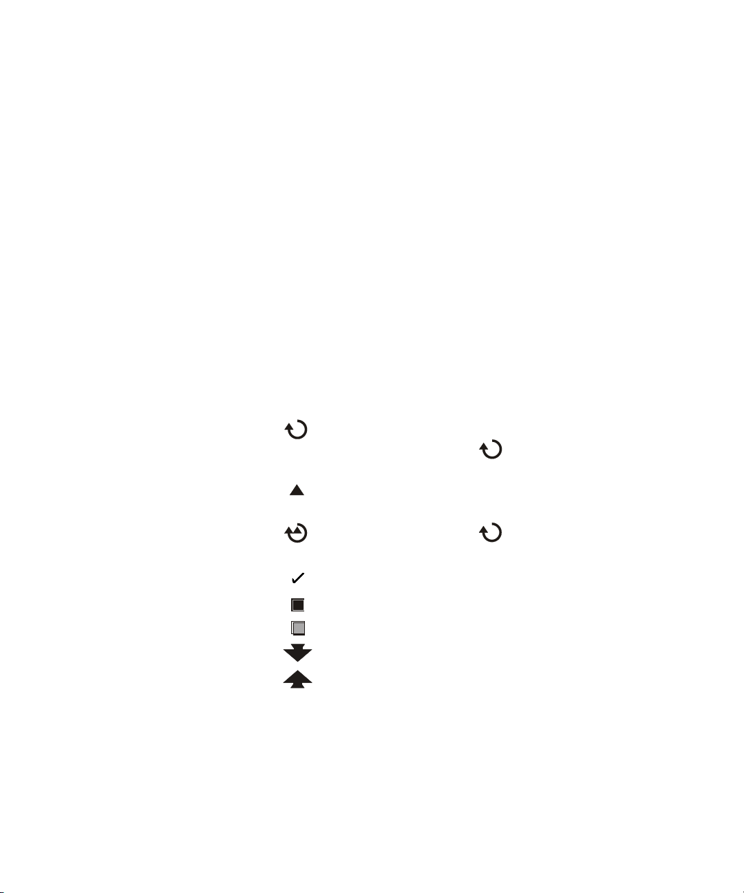
The following graphic symbols appear in the oscilloscope’s
softkey menus. The softkey menus appear at the bottom of the
display, just above the six softkeys.
Use the Entry knob to adjust the parameter. The Entry knob
is located on the front panel. The symbol above the knob is
illuminated when this control is active.
Front-Panel Controls 2
Press the softkey to display a pop up with a list of choices.
Repeatedly press the softkey until your choice is selected.
Use the Entry knob labeled or press the softkey to adjust
the parameter.
Option is selected and operational.
Feature is on. Press the softkey again to turn the feature off.
Feature is off. Press the softkey again to turn the feature on.
Press the softkey to view the menu.
Press the softkey to return to the previous menu.
6000 Series Oscilloscope User’s Guide 61
Page 62
2 Front-Panel Controls
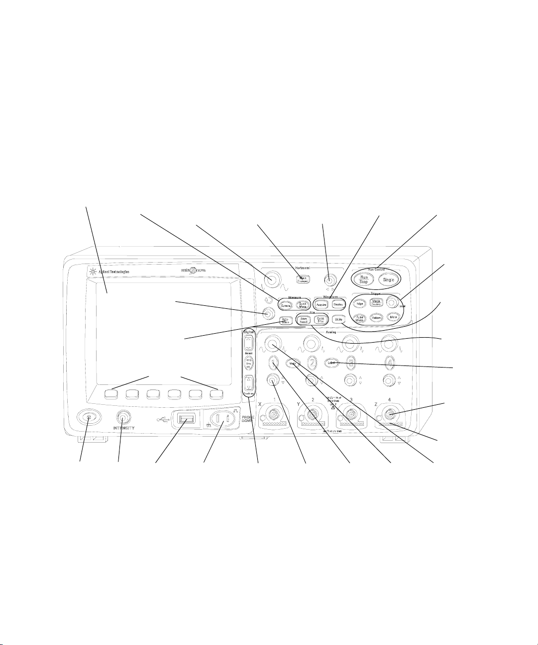
4-Channel 6000A Series Oscilloscope Front Panel
The following diagram shows the front panel of the 6000A
Series 4-channel oscilloscopes. The controls of the 2-channel
oscilloscopes are very similar. For a diagram showing the
differences of the 2-channel oscilloscope, see page 68.
22
Display
1
Power
switch
Measure
2
Intensity
Control
21
Keys
AutoScale
USB
Port
Sweep Speed
23
Entry
Knob
24
Key
25
Softkeys
3
20
Horizontal
Control
4
Probe
Compensation
Terminals
19
Horizontal
Main/Delayed
Key
5
Digital
Channel
Controls
Horizontal
Delay
Control
6
Vertical
Position
Control
18
7
Channel
On/Off
Key
17
Waveform
Keys
8
Math
Key
16
Run
Controls
15
Trigger
Controls
14
Utility
Key
13
File Keys
12
Label Key
11
Channel
Input BNC
10
AutoProbe
Interface
9
Vertical
Sensitivity
Control
Figure 1 6000A Series 4-Channel Oscilloscope Front Panel
62 6000 Series Oscilloscope User’s Guide
Page 63

Front Panel Controls
1. Power Switch Press once to switch power on; press again to
switch power off. See page 31.
2. Intensity Control Rotate clockwise to increase analog
waveform intensity; counterclockwise to decrease. You can vary
the intensity control to bring out signal detail, much like an
analog oscilloscope. Digital channel waveform intensity is not
adjustable. More details about using the Intensity control to
view signal detail are on page 243.
3. USB Host Port Connect a USB compliant mass storage device
to store or recall oscilloscope setup files or waveforms. You can
also use the USB port to update the oscilloscope’s system
software or Quick Help language files if updates are available.
You do not need to take special precautions before removing the
USB mass storage device from the oscilloscope (you do not need
to “eject” it). Simply unplug the USB mass storage device from
the oscilloscope when the file operation is complete. More
information on using the USB port is given in Chapter 7, “Saving
and Printing Data,” starting on page 281.
Front-Panel Controls 2
CAUTION
Only connect USB devices to the USB host port. Do not attempt to
connect a host computer to this port to control the oscilloscope. Use
the USB device port if you want to connect a host (See the 6000 Series
Oscilloscope Programmer’s Quick Start Guide for details).
4. Probe Compensation Terminals Use the signal at these
terminals to match each probe’s characteristics to the
oscilloscope channel to which it is connected. See page 48.
5. Digital Channel Controls These controls switch the digital
channels on/off, and can be used to select a digital channel for
repositioning on the display. You can press the D15 Thru D0 key
to show the Digital Channel Menu above the softkeys. See
Chapter 3, “Viewing and Measuring Digital Signals,” starting on
page 105.
6000 Series Oscilloscope User’s Guide 63
Page 64

2 Front-Panel Controls
6. Vertical Position Control Use this knob to change the
channel’s vertical position on the display. There is one Vertical
Position control for each channel. See “Using the analog
channels” on page 77.
7. Channel On/Off Key Use this key to switch the channel on or
off, or to access the channel’s menu in the softkeys. There is one
Channel On/Off key for each channel. See “Using the analog
channels” on page 77.
8. Math Key The Math key provides access to FFT (Fast Fourier
Transform), multiply, subtract, differentiate, and integrate
functions. See “Math Functions” on page 193.
9. Vertical Sensitivity Use this knob to change the vertical
sensitivity (gain) of the channel. See “Using the analog
channels” on page 77.
10. AutoProbe Interface (Not available on 100 MHz bandwidth
models.) When you connect a probe to the oscilloscope, the
AutoProbe Interface attempts to determine the type of probe
and set its parameters in the Probe menu accordingly. See
page 75. Note: Although the 100 MHz models lack the AutoProbe
interface, they do have a probe sense ring around the BNC.
Therefore, the probe attenuation factor will be automatically set
when you connect a compatible probe such as the 10073C or
10074C.
11. Channel Input BNC Connector Attach the oscilloscope probe
or BNC cable to the BNC connector. This is the channel’s input
connector.
12. Label Key Press this key to access the Label menu, which
lets you enter labels to identify each trace on the oscilloscope
display. See page 91.
13. File Keys Press the File key to access file functions such as
save or recall a waveform or setup. Or press the Quick Print key
to print the waveform from the display. See “Saving and
recalling traces and setups” on page 292.
64 6000 Series Oscilloscope User’s Guide
Page 65

Front-Panel Controls 2
14. Utility Key Press this key to access the Utility menu, which
lets you configure the oscilloscope’s I/O settings, printer
configuration, file explorer, service menu, and other options.
15. Trigger Controls These controls determine how the
oscilloscope triggers to capture data. See “Choosing Auto trigger
mode or Normal trigger mode” on page 74 and Chapter 4,
“Triggering the Oscilloscope,” starting on page 121.
16. Run Controls Press Run/Stop to make the oscilloscope begin
looking for a trigger. The Run/Stop key will illuminate in green.
If the trigger mode is set to “Normal,” the display will not
update until a trigger is found. If the trigger mode is set to
“Auto,” the oscilloscope looks for a trigger, and if none is found,
it will automatically trigger, and the display will immediately
show the input signals. In this case, the background of the Auto
indicator at the top of the display will flash, indicating that the
oscilloscope is forcing triggers.
Press Run/Stop again to stop acquiring data. The key will
illuminate in red. Now you can pan across and zoom-in on the
acquired data.
Press Single to make a single acquisition of data. The key will
illuminate in yellow until the oscilloscope triggers. See “To start
and stop an acquisition” on page 71.
17. Waveform Keys The Acquire key lets you set the
oscilloscope to acquire in Normal, Peak Detect, Averaging, or
High Resolution modes (see “Acquisition Modes” on page 245),
and lets you turn Realtime sampling off or on (see page 249).
The Display key lets you access the menu where you can select
infinite persistence (see page 241), switch vectors on or off (see
page 242), and adjust the display grid (graticule) intensity (see
page 242).
18. Horizontal Delay Control When the oscilloscope is running,
this control lets you set the acquisition window relative to the
trigger point. When the oscilloscope is stopped, you can turn
this knob to pan through the data horizontally. This lets you see
6000 Series Oscilloscope User’s Guide 65
Page 66

2 Front-Panel Controls
the captured waveform before the trigger (turn the knob
clockwise) or after the trigger (turn the knob counterclockwise).
See “To set up the Horizontal time base” on page 82.
19. Horizontal Main/Delayed Key Press this key to access the
menu where you can split the oscilloscope display into Main
and Delayed sections, and where you can select XY and Roll
modes. You can also select horizontal time/division vernier and
select the trigger time reference point on this menu. See “To set
up the Horizontal time base” on page 82.
20. Horizontal Sweep Speed Control Turn this knob to adjust the
sweep speed. This changes the time per horizontal division on
the display. When adjusted after the waveform has been
acquired and the oscilloscope is stopped, this has the effect of
stretching out or squeezing the waveform horizontally. See “To
set up the Horizontal time base” on page 82.
21. Measure Keys Press the Cursors key to switch on cursors
that you can use for making measurements. Press the Quick
Meas key to access a set of predefined measurements. See
Chapter 5, “Making Measurements,” starting on page 187.
22. Display The display shows captured waveforms using a
different color for each channel. For more information about
display modes see Chapter 6, “Displaying Data,” starting on
page 237. Signal detail is displayed using 256 levels of intensity.
For more information about viewing signal detail see “Varying
the intensity to view signal detail” on page 243.
23. Entry Knob The entry knob is used to select items from
menus and to change values. Its function changes based upon
which menu is displayed. Note that the curved arrow
symbol above the entry knob illuminates whenever the
entry knob can be used to select a value. Use the entry knob to
select among the choices that are shown on the softkeys.
66 6000 Series Oscilloscope User’s Guide
Page 67

Front-Panel Controls 2
24. AutoScale Key When you press the AutoScale key the
oscilloscope will quickly determine which channels have
activity, and it will turn these channels on and scale them to
display the input signals. See “How AutoScale Works” on
page 279
25. Softkeys The functions of these keys change based upon
the menus shown on the display directly above the keys.
6000 Series Oscilloscope User’s Guide 67
Page 68
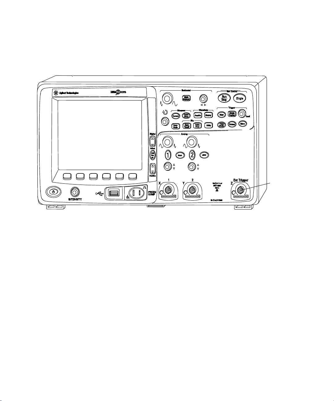
2 Front-Panel Controls
2-Channel 6000A Series Oscilloscope Front Panel (differences only)
External
Trigger
Input
Figure 2 6000A Series 2-Channel Oscilloscope Front Panel
The differences between the front panel of the 4-channel
oscilloscopes and the 2-channel oscilloscopes are:
• The 2-channel oscilloscope has two sets of channel controls
• The 2-channel oscilloscope’s external trigger input is on the
front panel instead of the rear panel. Some trigger features
differ. See “The External Trigger input” on page 130.
68 6000 Series Oscilloscope User’s Guide
Page 69
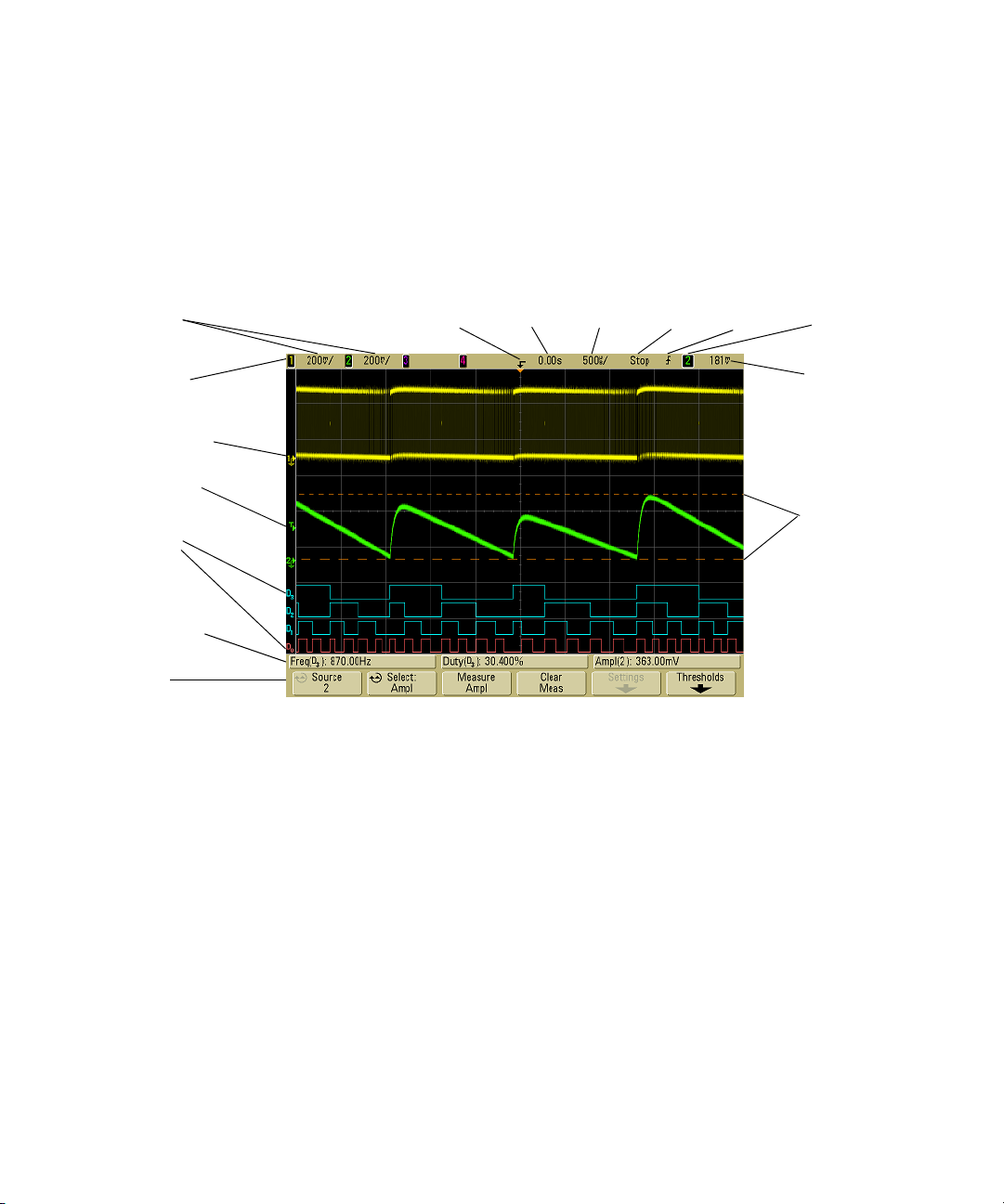
Interpreting the display
The oscilloscope display contains channel acquisitions, setup
information, measurement results, and softkeys for setting up
parameters.
Front-Panel Controls 2
Analog
channel
sensitivity
Status line
Analog
channels and
ground levels
Trigger Level
Digital
channels
Measurement
line
Softkeys
Trigger point,
time reference
Delay
time
Sweep
speed
Run/Sto
p mode
Trigger
type
Trigger
source
Trigger level
or digital
threshold
Cursor
markers
defining
measurement
Figure 3 Interpreting the display
Status line The top line of the display contains vertical,
horizontal, and trigger setup information.
Display area The display area contains the waveform
acquisitions, channel identifiers, and analog trigger and ground
level indicators. Each analog channel’s information appears in a
different color.
Measurement line This line normally contains automatic
measurement and cursor results, but can also display advanced
trigger setup data and menu information.
Softkeys The softkeys let you set up additional parameters for
the selected mode or menu.
6000 Series Oscilloscope User’s Guide 69
Page 70
2 Front-Panel Controls
6000A Series Front-Panel Operation
This section provides a brief overview of operating the
front-panel controls. Detailed oscilloscope operating
instructions are provided in later chapters.
Digital Channels
Because all of the oscilloscopes in the 6000 Series have analog channels, the
analog channel topics in this book apply to all instruments. Whenever a topic
discusses the digital channels, that information applies only to Mixed-Signal
Oscilloscope (MSO) models or DSO models that have been upgraded to an MSO.
To adjust the waveform intensity
The Intensity control is at the lower left corner of the front
panel near the power switch.
• To decrease waveform intensity, rotate the Intensity control
counter-clockwise.
• To increase waveform intensity, rotate the Intensity control
clockwise.
The intensity control does not affect digital channel intensity.
Digital channel intensity is fixed.
To adjust the display grid (graticule) intensity
1 Press the Display key.
2 Turn the Entry knob to change the intensity of the
displayed grid. The intensity level is shown in the Grid softkey
and is adjustable from 0 to 100%.
Each major vertical division in the grid corresponds to the
vertical sensitivity shown in the status line at the top of the
display.
Each major horizontal division in the grid corresponds to the
sweep speed time shown in the status line at the top of the
display.
70 6000 Series Oscilloscope User’s Guide
Page 71
Front-Panel Controls 2
NOTE
To change the analog waveform intensity, turn the Intensity knob at the
lower-left corner of the front panel. The digital waveform intensity is not
adjustable.
To start and stop an acquisition
• When you press the Run/Stop key, it illuminates in green and
the oscilloscope is in continuous running mode.
The oscilloscope examines the input voltage at each probe,
and updates the display whenever the trigger conditions are
met. Trigger processing and screen update rate are optimized
based on the oscilloscope settings. The oscilloscope displays
multiple acquisitions of the same signal similar to the way an
analog oscilloscope displays waveforms.
• When you press the Run/Stop key again, it illuminates in red,
and the oscilloscope is stopped.
“Stop” is displayed in the trigger mode position in the status
line at the top of the display. You can pan and zoom the
stored waveform by turning the horizontal and vertical
control knobs.
• To manually run and stop 6000L models start the Remote
Front Panel (see page 39) and select Run Control from the
Main Menu or press ctrl+R for run/stop or ctrl+S for single.
When the oscilloscope is running and you press the Run/Stop
key, it will flash until the current acquisition is completed. If the
acquisition completes immediately, the Run/Stop key will not
flash.
At slower sweep speeds, you may not want to wait for the
acquisition to finish. Just press Run/Stop again. The acquisition
will stop immediately and a partial waveform will be displayed.
You can display the results of multiple acquisitions using
infinite persistence. See “Infinite persistence” on page 241.
6000 Series Oscilloscope User’s Guide 71
Page 72
2 Front-Panel Controls
To make a single acquisition
Memory Depth/Record Length
Run/Stop versus Single
When the oscilloscope is running, the trigger processing and update rate are
optimized over the memory depth.
Single
Single acquisitions always use the maximum memory available—at least twice as
much memory as acquisitions captured in Run mode—and the oscilloscope
stores at least twice as many samples. At slow sweep speeds, the oscilloscope
operates at a higher sample rate when Single is used to capture an acquisition
due to the increased memory available. To acquire data with the longest possible
record length, press the Single key.
Running
When running, versus taking a single acquisition, the memory is divided in half.
This allows the acquisition system to acquire one record while processing the
previous acquisition, dramatically improving the number of waveforms per second
processed by the oscilloscope. While running, maximizing the rate at which
waveforms are drawn on the display provides the best picture of your input signal.
When you press the Single key it illuminates in yellow and the
oscilloscope starts the acquisition system, searching for the
trigger condition. When the trigger condition is met, the
captured waveform is displayed, the Single key is extinguished
and the Run/Stop key illuminates in red.
• Use the Single key to view single-shot events without
subsequent waveform data overwriting the display.
• To manually make a single acquisition on 6000L models start
the Remote Front Panel (see page 39) and select Run Control
from the Main Menu or press ctrl+S for single.
Use Single when you want the maximum sample rate and the
maximum memory depth for pan and zoom. (See “To pan and
zoom” on page 73)
1 Set the trigger mode to Normal (see “Trigger modes: Normal
and Auto” on page 125 for instructions).
This keeps the oscilloscope from automatically triggering
immediately.
72 6000 Series Oscilloscope User’s Guide
Page 73

Front-Panel Controls 2
2 If you are triggering on analog channel events, turn the
Trigger Level knob to the trigger threshold to a level that your
waveform will cross.
3 To begin a single acquisition, press the Single key.
When you press Single, the display is cleared, the trigger
circuitry is armed, the Single key is illuminated yellow, and
the oscilloscope will wait until a trigger condition occurs
before it displays a waveform.
When the oscilloscope triggers, the single acquisition is
displayed and the oscilloscope is stopped (the Run/Stop key is
illuminated in red).
4 To acquire another waveform, press Single again.
Auto Single
Auto-trigger will generate a trigger for you if one is not found in
the predetermined time (about 40 ms) after you press Single. If
you want to make a single acquisition and you are not
particularly interested in triggering the acquisition (for
example, if you are probing a DC level), set the trigger mode to
Auto (see page 125) and press the Single key. If a trigger
condition occurs, it will be used; if a trigger doesn’t happen, an
untriggered acquisition will be taken.
To pan and zoom
You can pan across and zoom-in on a waveform even when the
acquisition system is stopped.
1 Press the Run/Stop key to stop acquisitions (or press the
Single key and allow the oscilloscope to acquire the waveform
and stop). The Run/Stop key is illuminated red when the
oscilloscope is stopped.
2 Turn the sweep speed knob to zoom horizontally and turn the
volts/division knob to zoom vertically.
The ∇ symbol at the top of the display indicates the time
reference point where the zoom-in/zoom-out is referenced.
3 Turn the Delay Time knob () to pan horizontally and turn
the channel’s vertical position knob ( ) to pan vertically.
6000 Series Oscilloscope User’s Guide 73
Page 74

2 Front-Panel Controls
Choosing Auto trigger mode or Normal trigger mode
The stopped display may contain several triggers worth of
information, but only the last trigger acquisition is available for
pan and zoom.
For more information about Pan and Zoom see page 238.
In Auto trigger mode, the oscilloscope automatically triggers
and captures waveforms when you press Run.
If you press Run when the oscilloscope is in Normal trigger
mode, a trigger must be detected before an acquisition can
complete.
In many cases, a triggered display is not needed to check signal
levels or activity. For these applications, use Auto trigger mode
(which is the default setting). If you only want to acquire
specific events as specified by the trigger settings, use Normal
trigger mode.
You can select the trigger mode by pressing the Mode/Coupling
key, then the Mode softkey.
For more detailed discussion of Auto trigger mode and Normal
trigger mode, see “Trigger modes: Normal and Auto” on page 125.
Using AutoScale
To configure the oscilloscope quickly, press the AutoScale key to
display the connected signal(s) that are active.
To undo the effects of AutoScale, press the Undo AutoScale
softkey before pressing any other key. This is useful if you have
unintentionally pressed the AutoScale key or do not like the
settings AutoScale has selected and want to return to your
previous settings.
To make the oscilloscope remain in the acquisition mode you
have chosen, press the AutoScale Acq Mode softkey and select
Preserve Acquisition Mode. Otherwise, the acquisition mode will
default to Normal whenever the AutoScale key is pressed.
74 6000 Series Oscilloscope User’s Guide
Page 75
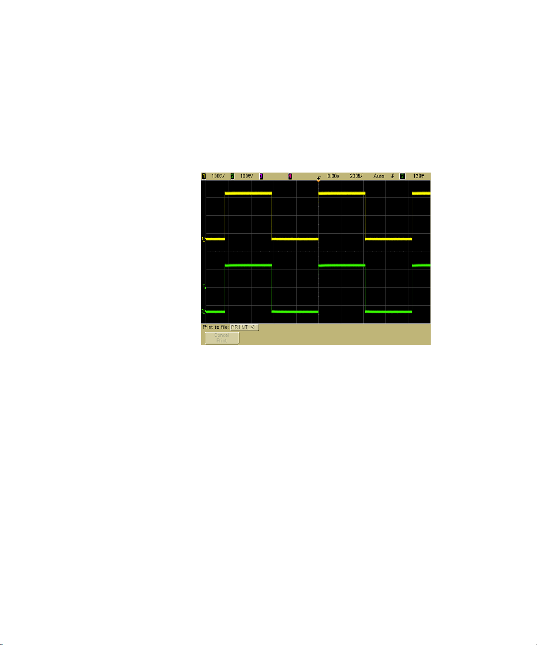
Front-Panel Controls 2
Example Connect the oscilloscope probes for channels 1 and 2 to the
Probe Comp output on the front panel of the instrument. Be
sure to connect the probe ground leads to the ground lug beside
the Probe Comp output. Set the instrument to the factory
default configuration by pressing the Save/Recall key, then the
Default Setup softkey. Then press the AutoScale key. You should
see a display similar to the one shown below.
Figure 4 AutoScale of oscilloscope channels 1 and 2
For an explanation of how AutoScale works, see “How
AutoScale Works” on page 279.
To set the probe attenuation factor
Passive Probes
All 6000 Series oscilloscopes including the 100 MHz models
recognize passive probes such as the 10073C and 10074C. These
probes have a pin on their connector that connects to the ring
around the oscilloscope’s BNC connector. Therefore, the
oscilloscope will automatically set the attenuation factor for
recognized Agilent passive probes.
6000 Series Oscilloscope User’s Guide 75
Page 76

2 Front-Panel Controls
Passive probes that do not have a pin that connects to the ring
around the BNC connector will not be recognized by the
oscilloscope, and you must set the probe attenuation factor
manually.
Active Probes
All 6000 Series oscilloscopes except the 100 MHz bandwidth
models (MSO/DSO6012A and MSO/DSO6014A/L) have an
AutoProbe interface. Most Agilent active probes are compatible
with the AutoProbe interface. The AutoProbe interface uses a
series of contacts directly below the channel’s BNC connector to
transfer information between the oscilloscope and the probe.
When you connect a compatible probe to the oscilloscope, the
AutoProbe interface determines the type of probe and sets the
oscilloscope’s parameters (units, offset, attenuation, coupling,
and impedance) accordingly.
Manually Setting the Probe Attenuation Factor
If you connect a probe that the oscilloscope does not
automatically identify, you can set the attenuation factor as
follows:
1 Press the channel key
2 Press the Probe softkey
3 Turn the Entry knob to set the attenuation factor for the
connected probe.
The attenuation factor can be set from 0.1:1 to 1000:1 in a 1-2-5
sequence. The probe attenuation factor must be set properly for
measurements to be made correctly.
76 6000 Series Oscilloscope User’s Guide
Page 77
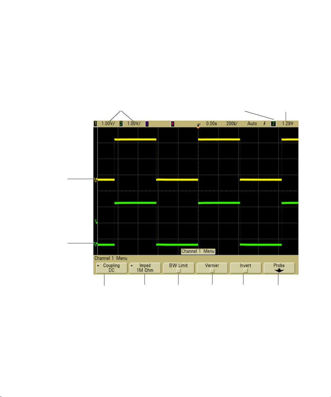
Channel 1
ground level
Using the analog channels
Connect the oscilloscope probes for channels 1 and 2 to the
Probe Comp output on the front panel of the instrument.
1 Press the 1 key in the Analog section of the oscilloscope’s
front panel to display the Channel 1 menu.
Channel,
Volts/div
Front-Panel Controls 2
Trigger
source
Trigger level
or threshold
Channel 2
ground level
Channel
coupling
Input
impedance
Bandwidth
limit
Channel
vernier
Invert
channel
Probe
menu
Pressing an analog channel key displays the channel’s menu
and turns the display of the channel on or off. The channel is
displayed when the key is illuminated.
On 6000L models, select Analog from the Main Menu and use
the menu.
6000 Series Oscilloscope User’s Guide 77
Page 78
2 Front-Panel Controls
Turning channels off
You must be viewing the menu for a channel before you can turn it off. For
example, if channel 1 and channel 2 are turned on and the menu for channel 2 is
being displayed, to turn channel 1 off, press 1 to display channel 1 menu, then
press 1 again to turn channel 1 off.
Vertical sensitivity Turn the large knob above the channel key
to set the sensitivity (volts/division) for the channel. The
vertical sensitivity knob changes the analog channel sensitivity
in a 1-2-5 step sequence (with a 1:1 probe attached). The analog
channel Volts/Div value is displayed in the status line.
Vernier Press the Vernier softkey to turn on vernier for the
selected channel. When Vernier is selected, you can change the
channel’s vertical sensitivity in smaller increments. The channel
sensitivity remains fully calibrated when Vernier is on. The
vernier value is displayed in the status line at the top of the
display.
When Vernier is turned off, turning the volts/division knob
changes the channel sensitivity in a 1-2-5 step sequence.
Vertical expansion The default mode for expanding the signal
when you turn the volts/division knob is vertical expansion
about the ground level of the channel. To set the expansion
mode to expand about the center of the screen instead, press
Expand in the Utility&Options&Preferences&Expand menu and
select Center.
Ground level The ground level of the signal for each displayed
analog channel is identified by the position of the icon at the
far-left side of the display.
Vertical posit ion Turn the small vertical position knob ( ) to
move the channel’s waveform up or down on the display. The
voltage value momentarily displayed in the upper right portion
of the display represents the voltage difference between the
vertical center of the display and the ground level ( ) icon. It
also represents the voltage at the vertical center of the display if
vertical expansion is set to expand about ground.
78 6000 Series Oscilloscope User’s Guide
Page 79
Front-Panel Controls 2
Measurement Hints
If the channel is DC coupled, you can quickly measure the DC component of the
signal by simply noting its distance from the ground symbol.
If the channel is AC coupled, the DC component of the signal is removed, allowing
you to use greater sensitivity to display the AC component of the signal.
2 Press the channel’s on/off key, then press the Coupling softkey
to select the input channel coupling.
Coupling changes the channel's input coupling to either AC
(alternating current) or DC (direct current). AC coupling
places a 3.5 Hz high-pass filter in series with the input
waveform that removes any DC offset voltage from the
waveform. When AC is selected, “AC” is illuminated on the
front panel next to the channel position knob ( ).
• DC coupling is useful for viewing waveforms as low as
0 Hz that do not have large DC offsets.
• AC coupling is useful for viewing waveforms with large DC
offsets. When AC coupling is chosen, you cannot select
50Ω mode. This is done to prevent damage to the
oscilloscope.
Note that Channel Coupling is independent of Trigger Coupling.
To change Trigger coupling see page 127.
3 Press the Imped (impedance) softkey.
NOTE
The input impedance of the MSO/DSO6012A and MSO/DSO6014A/L
(100 MHz bandwidth) oscilloscope is fixed at 1 MΩ. Therefore, the
impedance selection is not available on these models.
When you connect an AutoProbe, self-sensing probe, or a compatible
InfiniiMax probe, the oscilloscope will automatically configure the
oscilloscope to the correct impedance.
The analog channel input impedance can be set to either
1M Ohm or 50 Ohm by pressing the Imped softkey.
6000 Series Oscilloscope User’s Guide 79
Page 80

2 Front-Panel Controls
• 50 Ohm mode matches 50-ohm cables commonly used in
making high frequency measurements, and 50-ohm active
probes. This impedance matching gives you the most
accurate measurements since reflections are minimized
along the signal path. When 50 Ohm is selected, “50Ω” is
illuminated on the front panel next to the channel position
knob. The oscilloscope automatically switches to 1 M Ohm
mode to prevent possible damage if AC coupling is
selected.
• 1M Ohm mode is for use with many passive probes and for
general-purpose measurements. The higher impedance
minimizes the loading effect of the oscilloscope on the
circuit under test.
4 Press the BW Limit softkey to turn on bandwidth limiting.
Pressing the BW Limit softkey turns the bandwidth limit on or
off for the selected channel. When bandwidth limit is on, the
maximum bandwidth for the channel is approximately
25 MHz on the 300 MHz, 500 MHz, and 1 GHz bandwidth
oscilloscope models and approximately 20 MHz for the
100 MHz bandwidth oscilloscope models. For waveforms
with frequencies below this, turning bandwidth limit on
removes unwanted high frequency noise from the waveform.
The bandwidth limit also limits the trigger signal path of any
channel that has BW Limit turned on.
When BW Limit is selected, “BW” is illuminated on the front
panel next to the channel position knob ( ).
5 Press the Invert softkey to invert the selected channel.
When Invert is selected, the voltage values of the displayed
waveform are inverted. Invert affects how a channel is
displayed, but does not affect triggering. If the oscilloscope is
set to trigger on a rising edge, it remains set to trigger on a
same edge (triggers at the same point on the waveform) after
the channel is inverted.
Inverting a channel will also change the result of any
function selected in the Math menu or any measurement.
6 Press the Probe softkey to display the channel probe menu.
80 6000 Series Oscilloscope User’s Guide
Page 81
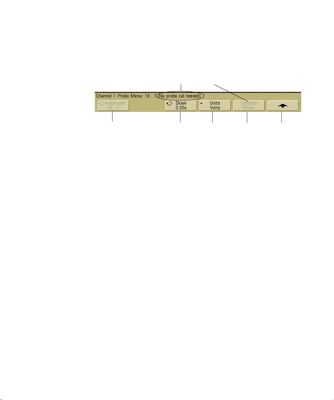
Front-Panel Controls 2
This menu lets you select additional probe parameters such
as attenuation factor and units of measurement for the
connected probe.
Probe calibration not needed, not available.
Attenuation
factor
Skew adjust
Measurement
units
Calibrate
probe
Return to
previous menu
• Probe Attenuation — See “To set the probe attenuation
factor” on page 75.
• Skew — When measuring time intervals in the ns range,
small differences in cable length can affect the
measurement. Use Skew to remove cable-delay errors
between any two channels.
Probe the same point with both probes, then press Skew
and turn the Entry knob to enter the amount of skew
between channels. Each analog channel can be adjusted
±100 ns in 10 ps increments for a total of 200 ns
difference.
The skew setting is reset to zero when you press
Save/Recall&Default Setup.
• Probe Units — Press the Units softkey to select the proper
measurement unit for the connected probe. Select Volts for
a voltage probe and select Amps for a current probe.
Channel sensitivity, trigger level, measurement results,
and math functions will reflect the measurement units you
have selected.
• Calibrate Probe — See “To calibrate the probes” on page 49.
6000 Series Oscilloscope User’s Guide 81
Page 82
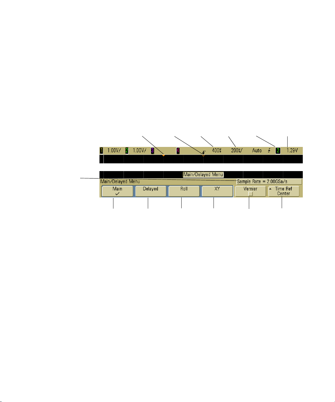
2 Front-Panel Controls
To set up the Horizontal time base
1 Press the Main/Delayed key in the Horizontal section of the
front panel.
To manually control the horizontal time base on 6000L models
start the Remote Front Panel (see page 39) and select Horizontal
from the Main Menu or press ctrl+N.
Current
sample rate
Main sweep
mode
The Main/Delayed menu lets you select the horizontal mode
(Main, Delayed, Roll, or XY), and set the time base vernier and
time reference.
The current sample rate is displayed above the Vernier and Time
Ref softkeys.
Main mode
1 Press the Main softkey to select Main horizontal mode.
Trigger
point
Delayed
sweep mode
Time
reference
Roll
mode
Delay
time
XY
mode
Sweep
speed
Trigger
source
Time base
vernier
Trigger level
or threshold
Time
reference
Main horizontal mode is the normal viewing mode for the
oscilloscope.When the oscilloscope is stopped, you can use
the Horizontal knobs to pan and zoom the waveform.
2 Turn the large knob (time/division) in the Horizontal section
and notice the change it makes to the status line.
82 6000 Series Oscilloscope User’s Guide
Page 83

Front-Panel Controls 2
When the oscilloscope is running in Main mode, use the large
Horizontal knob to change sweep speed and use the small
knob ( ) to set the delay time. When the oscilloscope is
stopped, use these knobs to pan and zoom your waveform.
The sweep speed (seconds/division) value is displayed in the
status line.
3 Press the Vernie r softkey to turn on the time base vernier.
The Ver nier softkey lets you change the sweep speed in
smaller increments with the time/division knob. The sweep
speed remains fully calibrated when Vernier is on. The value
is displayed in the status line at the top of the display.
When Vernier is turned off, the Horizontal sweep speed knob
changes the time base sweep speed in a 1-2-5 step sequence.
4 Note the setting of the Time Ref (time reference) softkey.
Time reference is the reference point on the display for delay
time. Time reference can be set to one major division from
the left or right edge, or to the center of the display.
A small hollow triangle (∇
) at the top of the display grid
marks the position of the time reference. When delay time is
set to zero, the trigger point indicator () overlays the time
reference indicator.
Turning the Horizontal sweep speed knob will expand or
contract the waveform about the time reference point (∇).
Turning the Horizontal delay time ( ) knob in Main mode
will move the trigger point indicator () to the left or right of
the time reference point (∇).
The time reference position sets the initial position of the
trigger event within acquisition memory and on the display,
with delay set to 0. The delay setting sets the specific location
of the trigger event with respect to the time reference
position. The time reference setting affects the delayed sweep
as described in the following ways:
• When the horizontal mode is set to Main, the delay knob
positions the main sweep relative to the trigger. This delay
is a fixed number. Changing this delay value does not
affect the sweep speed.
6000 Series Oscilloscope User’s Guide 83
Page 84

2 Front-Panel Controls
• When the horizontal mode is set to Delayed, the delay
knob controls the position of the delayed sweep window
inside the main sweep display. This delay value is
independent of sampling interval and sweep speed.
Changing this delay value does not effect the position of
the main window.
5 Turn the delay knob ( ) and notice that its value is
displayed in the status line.
The delay knob moves the main sweep horizontally, and it
pauses at 0.00 s, mimicking a mechanical detent. Changing
the delay time moves the sweep horizontally and indicates
how far the trigger point (solid inverted triangle) is from the
time reference point (hollow inverted triangle ∇). These
reference points are indicated along the top of the display
grid. The previous figure shows the trigger point with the
delay time set to 400 µs. The delay time number tells you how
far the time reference point is located from the trigger point.
When delay time is set to zero, the delay time indicator
overlays the time reference indicator.
All events displayed left of the trigger point happened before
the trigger occurred, and these events are called pre-trigger
information. You will find this feature very useful because
you can now see the events that led up to the trigger point.
Everything to the right of the trigger point is called
post-trigger information. The amount of delay range
(pre-trigger and post-trigger information) available depends
on the sweep speed selected and memory depth.
Delayed mode
Delayed sweep is an expanded version of main sweep. When
Delayed mode is selected, the display divides in half and the
delayed sweep icon displays in the middle of the line at the
top of the display. The top half of the display shows the main
sweep and the bottom half displays the delayed sweep.
Delayed sweep is a magnified portion of the main sweep. You
can use delayed sweep to locate and horizontally expand part of
the main sweep for a more detailed (higher-resolution) analysis
of signals.
84 6000 Series Oscilloscope User’s Guide
Page 85

Front-Panel Controls 2
The following steps show you how to use delayed sweep. Notice
that the steps are very similar to operating the delayed sweep in
analog oscilloscopes.
1 Connect a signal to the oscilloscope and obtain a stable
display.
2 Press Main/Delayed.
3 Press the Delayed softkey.
To change the sweep speed for the delayed sweep window, turn
the sweep speed knob. As you turn the knob, the sweep speed is
highlighted in the status line above the waveform display area.
The area of the main display that is expanded is intensified and
marked on each end with a vertical marker. These markers
show what portion of the main sweep is expanded in the lower
half. The Horizontal knobs control the size and position of the
delayed sweep. The delay value is momentarily displayed in the
upper-right portion of the display when the delay time ( )
knob is turned.
To change the sweep speed for the main sweep window, press
the Main softkey, then turn the sweep speed knob.
6000 Series Oscilloscope User’s Guide 85
Page 86
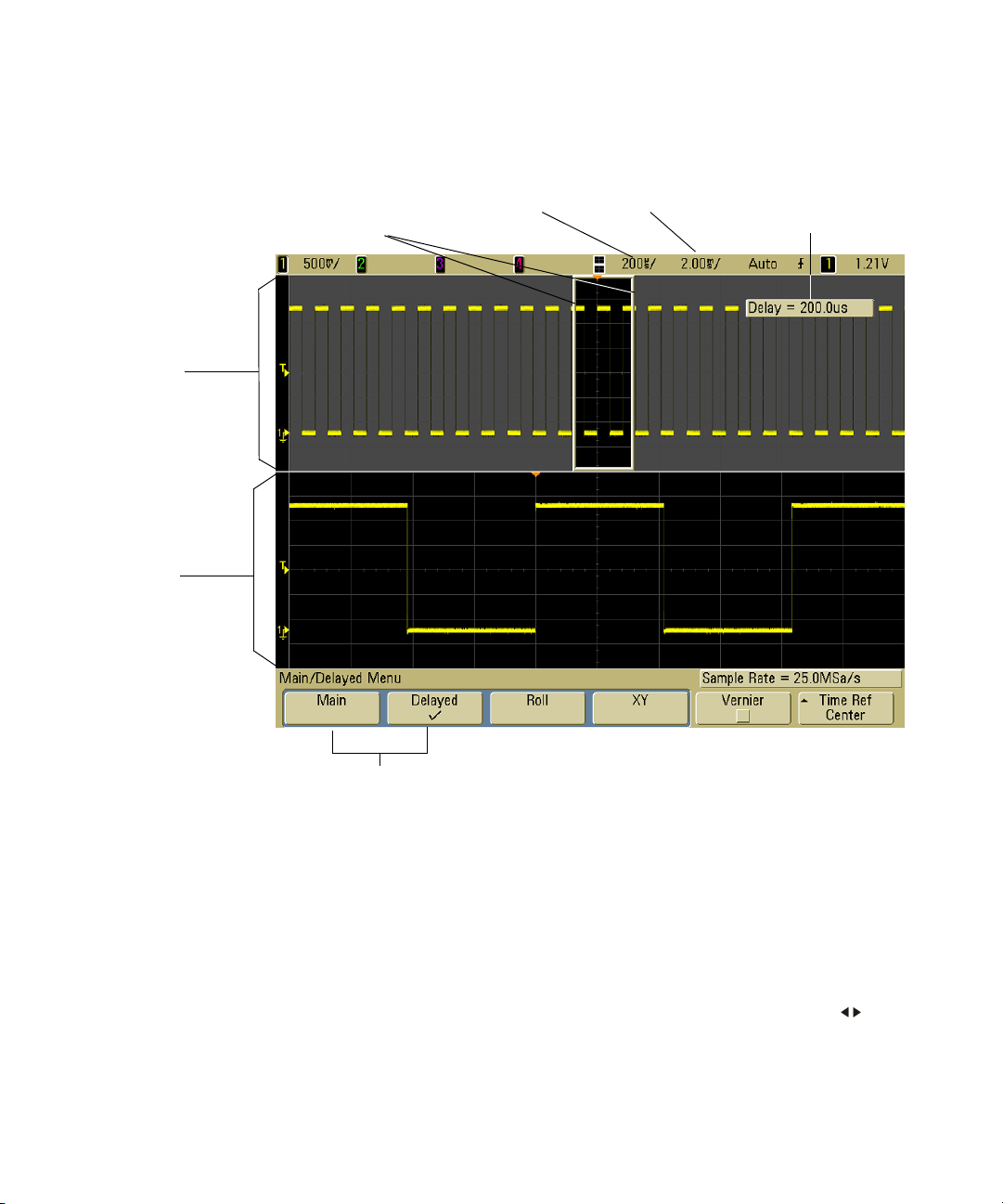
2 Front-Panel Controls
Main sweep
window
Delayed sweep
window
These markers define the
beginning and end of the
delayed sweep window
Time/div for
delayed sweep
Time/div for
main sweep
Delay time
momentarily displays
when the delay time
knob is turned
Select main or
delayed sweep
The area of the main display that is expanded is intensified and
marked on each end with a vertical marker. These markers
show what portion of the main sweep is expanded in the lower
half. The Horizontal knobs control the size and position of the
delayed sweep. The delay value is momentarily displayed in the
upper-right portion of the display when the delay time ( )
knob is turned.
86 6000 Series Oscilloscope User’s Guide
Page 87

Front-Panel Controls 2
To change the sweep speed for the delayed sweep window, turn
the sweep speed knob. As you turn the knob, the sweep speed is
highlighted in the status line above the waveform display area.
The time reference position sets the initial position of the
trigger event within acquisition memory and on the display,
with delay set to 0. The delay setting sets the specific location of
the trigger event with respect to the time reference position.
The time reference setting affects the delayed sweep in the
following ways.
When the horizontal mode is set to Main, the delay positions the
main sweep relative to the trigger. This delay is a fixed number.
Changing this delay value does not affect the sweep speed.
When the horizontal mode is set to Delayed, the delay controls
the position of the delayed sweep window inside the main
sweep display. This delay value is independent of sampling
interval and sweep speed.
To change the sweep speed for the main sweep window, press
the Main softkey, then turn the sweep speed knob.
For information about using delayed mode for measurements,
refer to Chapter 5, “Making Measurements,” starting on page
187.
Roll mode
• Press the Main/Delayed key, then press the Roll softkey.
• Roll mode causes the waveform to move slowly across the
screen from right to left. It only operates on time base
settings of 500 ms/div and slower. If the current time base
setting is faster than the 500 ms/div limit, it will be set to
500 ms/div when Roll mode is entered.
• In Normal horizontal mode, signal events occurring before
the trigger are plotted to the left of the trigger point (t) and
signal events after the trigger plotted to the right of the
trigger point.
6000 Series Oscilloscope User’s Guide 87
Page 88
2 Front-Panel Controls
• In Roll mode there is no trigger. The fixed reference point on
the screen is the right edge of the screen and refers to the
current moment in time. Events that have occurred are
scrolled to the left of the reference point. Since there is no
trigger, no pre-trigger information is available.
If you would like to pause the display in Roll mode press the
Single key. To clear the display and restart an acquisition in Roll
mode, press the Single key again.
Use Roll mode on low-frequency waveforms to yield a display
much like a strip chart recorder. It allows the waveform to roll
across the display.
XY mode
XY mode changes the display from a volts-versus-time display to
a volts-versus-volts display. The time base is turned off. Channel
1 amplitude is plotted on the X-axis and Channel 2 amplitude is
plotted on the Y-axis.
You can use XY mode to compare frequency and phase
relationships between two signals. XY mode can also be used
with transducers to display strain versus displacement, flow
versus pressure, volts versus current, or voltage versus
frequency.
Use the cursors to make measurements on XY mode waveforms.
For more information about using XY mode for measurements,
refer to “To use the XY horizontal mode” on page 188.
Z-Axis Input in XY Display Mode (Blanking)
When you select the XY display mode, the time base is turned off. Channel 1 is the
X-axis input, channel 2 is the Y-axis input, and channel 4 (or the External trigger
on 2-channel models) is the Z-axis input. If you only want to see portions of the Y
versus X display, use the Z-axis input. Z-axis turns the trace on and off (analog
oscilloscopes called this Z-axis blanking because it turned the beam on and off).
When Z is low (<1.4 V), Y versus X is displayed; when Z is high (>1.4 V), the trace
is turned off.
88 6000 Series Oscilloscope User’s Guide
Page 89

To make cursor measurements
You can use the cursors to make custom voltage or time
measurements on oscilloscope signals, and timing
measurements on digital channels.
• To manually control Cursors on 6000L models start the
Remote Front Panel (see page 39) and select Measure from
the Main Menu or press ctrl+C to access the oscilloscope’s
Cursors Menu.
1 Connect a signal to the oscilloscope and obtain a stable
display.
2 Press the Cursors key. View the cursor functions in the
softkey menu:
• Mode — Set the cursors to measure voltage and time
(Normal), or display the binary or hexadecimal logic value
of the displayed waveforms.
• Source — selects a channel or math function for the cursor
measurements.
• X Y — Select either the X cursors or the Y cursors for
adjustment with the Entry knob.
• X1 and X2 — adjust horizontally and normally measure
time.
• Y1 and Y2 — adjust vertically and normally measure
voltage.
• X1 X2 and Y1 Y2 — move the cursors together when turning
the Entry knob.
Front-Panel Controls 2
NOTE
6000 Series Oscilloscope User’s Guide 89
If you intend to make cursor measurements on a trace that you recall from
memory, be sure to recall both setup and trace. See “To recall traces and
setups” on page 297.
For more information about using the cursors, see “To make
cursor measurements” on page 210.
Page 90

2 Front-Panel Controls
To make automatic measurements
You can use automatic measurements on any channel source or
any running math function. Cursors are turned on to focus on
the most recently selected measurement (right-most on the
measurement line above the softkeys on the display).
1 Press the Quick Meas key to display the automatic
measurement menu.
To manually control Quick Measurements on 6000L models
start the Remote Front Panel (see page 39) and select
Measure from the Main Menu or press ctrl+M to access the
oscilloscope’s Quick Measurements Menu.
2 Press the Source softkey to select the channel or running
math function to be measured.
Only channels or math functions that are displayed are
available for measurements. If you choose an invalid source
channel for a measurement, the measurement will default to
the nearest in the list that makes the source valid.
If a portion of the waveform required for a measurement is
not displayed or does not display enough resolution to make
the measurement, the result will be displayed with a message
such as greater than a value, less than a value, not enough
edges, not enough amplitude, incomplete, or waveform is
clipped to indicate that the measurement may not be reliable.
3 Choose a type of measurement by pressing the Select softkey,
then turn the Entry knob to select the desired
measurement from the popup list.
4 Press the Measure softkey to make the selected measurement.
5 To stop making measurements and erase the measurement
results from the measurement line above the softkeys, press
the Clear Meas softkey.
For more information about automatic measurements, see
“Automatic Measurements” on page 217.
90 6000 Series Oscilloscope User’s Guide
Page 91
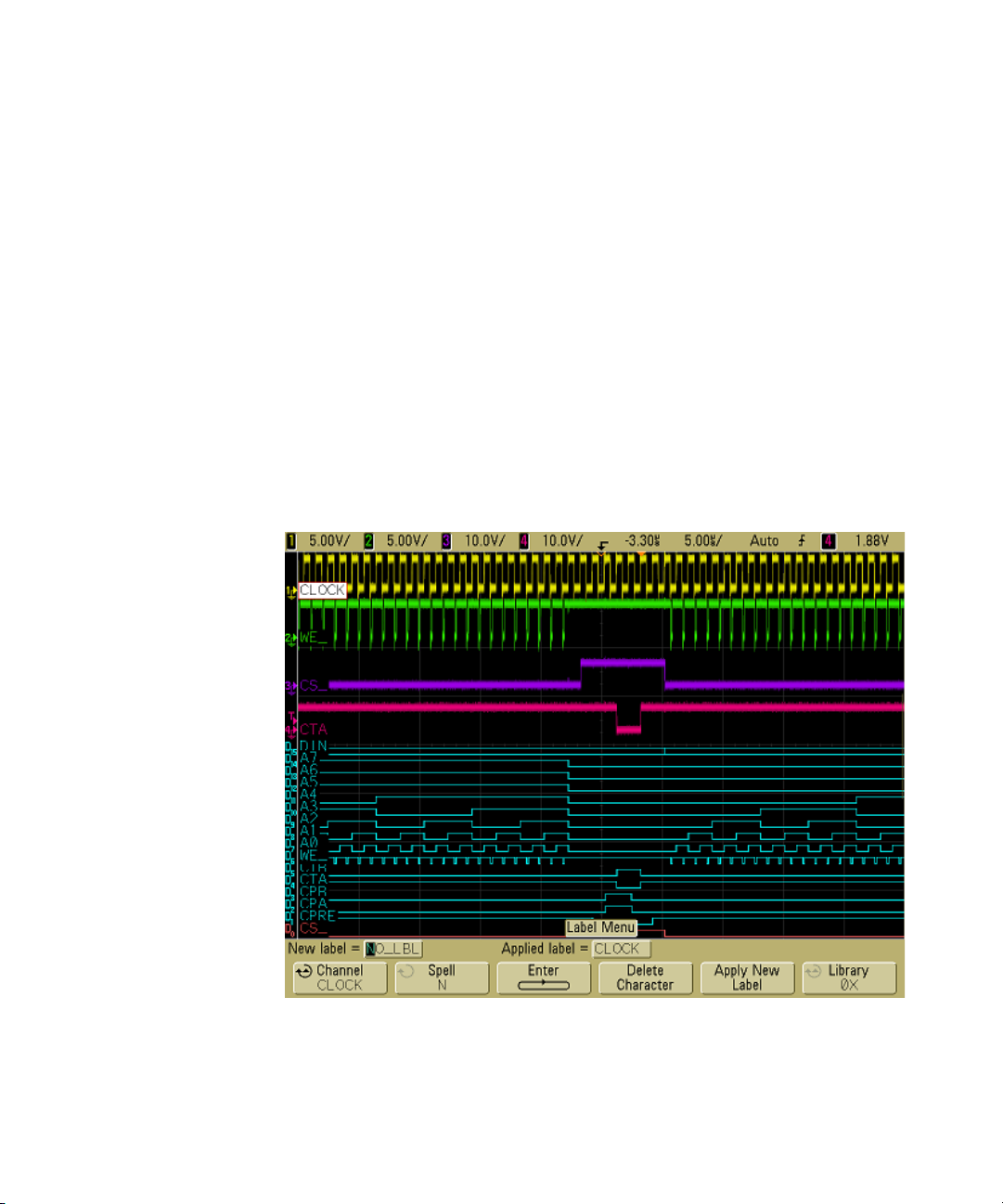
Using Labels
Front-Panel Controls 2
You can define labels and assign them to each analog input
channel, or you can turn labels off to increase the waveform
display area. Labels can also be applied to digital channels on
MSO models.
To turn the label display on or off
1 Press the Label key on the front panel.
This turns on display labels for the analog and digital
channels. When the Label key is illuminated, the labels for
displayed channels are displayed at the left edge of the
displayed traces. The figure below shows an example of the
default labels assigned when you turn the label display on.
The channel labels default to their channel number.
2 To turn the labels off, press the Label key until it is not
illuminated.
6000 Series Oscilloscope User’s Guide 91
Page 92
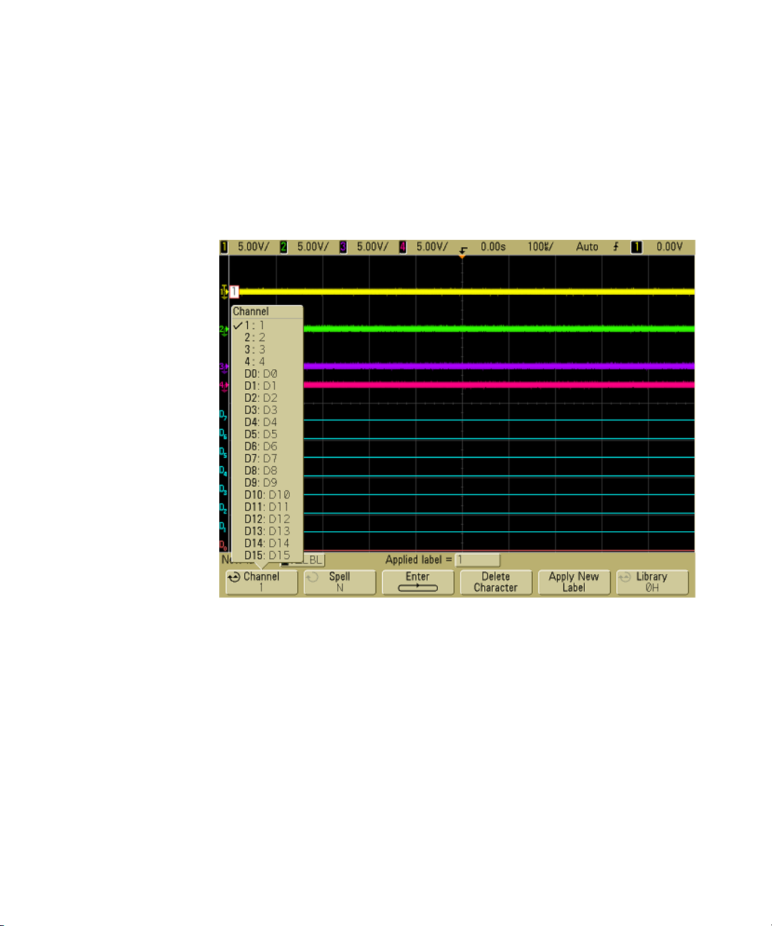
2 Front-Panel Controls
To assign a predefined label to a channel
1 Press the Label key.
2 Press the Channel softkey, then turn the Entry knob or
successively press the Channel softkey to select a channel for
label assignment.
The figure above shows the list of channels and their default
labels. The channel does not have to be turned on to have a
label assigned to it.
3 Press the Library softkey, then turn the Entry knob or
successively press the Library softkey to select a predefined
label from the library.
4 Press the Apply New Label softkey to assign the label to your
selected channel.
5 Repeat the above procedure for each predefined label you
want to assign to a channel.
92 6000 Series Oscilloscope User’s Guide
Page 93
Front-Panel Controls 2
To define a new label
1 Press the Label key.
2 Press the Channel softkey, then turn the Entry knob or
successively press the softkey to select a channel for label
assignment.
The channel does not have to be turned on to have a label
assigned to it. If the channel is turned on, its current label
will be highlighted.
3 Press the Spell softkey, then turn the Entr y knob to select the
first character in the new label.
Turning the Entry knob selects a character to enter into the
highlighted position shown in the "New label =" line above
the softkeys and in the Spell softkey. Labels can be up to six
characters in length.
4 Press the Enter softkey to enter the selected character and to
go to the next character position.
You may position the highlight on any character in the label
name by successively pressing the Enter softkey.
5 To delete a character from the label, press the Enter softkey
until the letter you want to delete is highlighted, then press
the Delete Character softkey.
6 When you are done entering characters for the label, press
the Apply New Label softkey to assign the label to the selected
channel.
When you define a new label, it is added to the nonvolatile label
list.
Label Assignment Auto-Increment Features
When you assign a label ending in a digit, such as ADDR0 or DATA0, the
oscilloscope automatically increments the digit and displays the modified label in
the “New label” field after you press the Apply New Label softkey. Therefore, you
only need to select a new channel and press the Apply New Label softkey again
to assign the label to the channel. Only the original label is saved in the label list.
This feature makes it easier to assign successive labels to numbered control lines
and data bus lines.
6000 Series Oscilloscope User’s Guide 93
Page 94
2 Front-Panel Controls
Label List Management
When you press the Library softkey, you will see a list of the last 75 labels used.
The list does not save duplicate labels. Labels can end in any number of trailing
digits. As long as the base string is the same as an existing label in the library, the
new label will not be put in the library. For example, if label A0 is in the library and
you make a new label called A12345, the new label is not added to the library.
When you save a new user-defined label, the new label will replace the oldest
label in the list. Oldest is defined as the longest time since the label was last
assigned to a channel. Any time you assign any label to a channel, that label will
move to the newest in the list. Thus, after you use the label list for a while, your
labels will predominate, making it easier to customize the instrument display for
your needs.
When you reset the label library list (see next topic), all of your custom labels will
be deleted, and the label list will be returned to its factory configuration.
To reset the label library to the factory default
1 Press Utility&Options&Preferences.
CAUTION
Pressing the Default Library softkey will remove all user-defined labels
from the library and set the labels back to the factory default. Once
deleted, these user-defined labels cannot be recovered.
2 Press the Default Library softkey.
This will delete all user-defined labels from the library and
set the labels in the library back to the factory default.
However, this does not default the labels currently assigned
to the channels (those labels that appear in the waveform
area).
Defaulting labels without erasing the default library.
Selecting Default Setup in the Save/Recall menu will set all channel labels back
to the default labels but does not erase the list of user-defined labels in the
library.
94 6000 Series Oscilloscope User’s Guide
Page 95
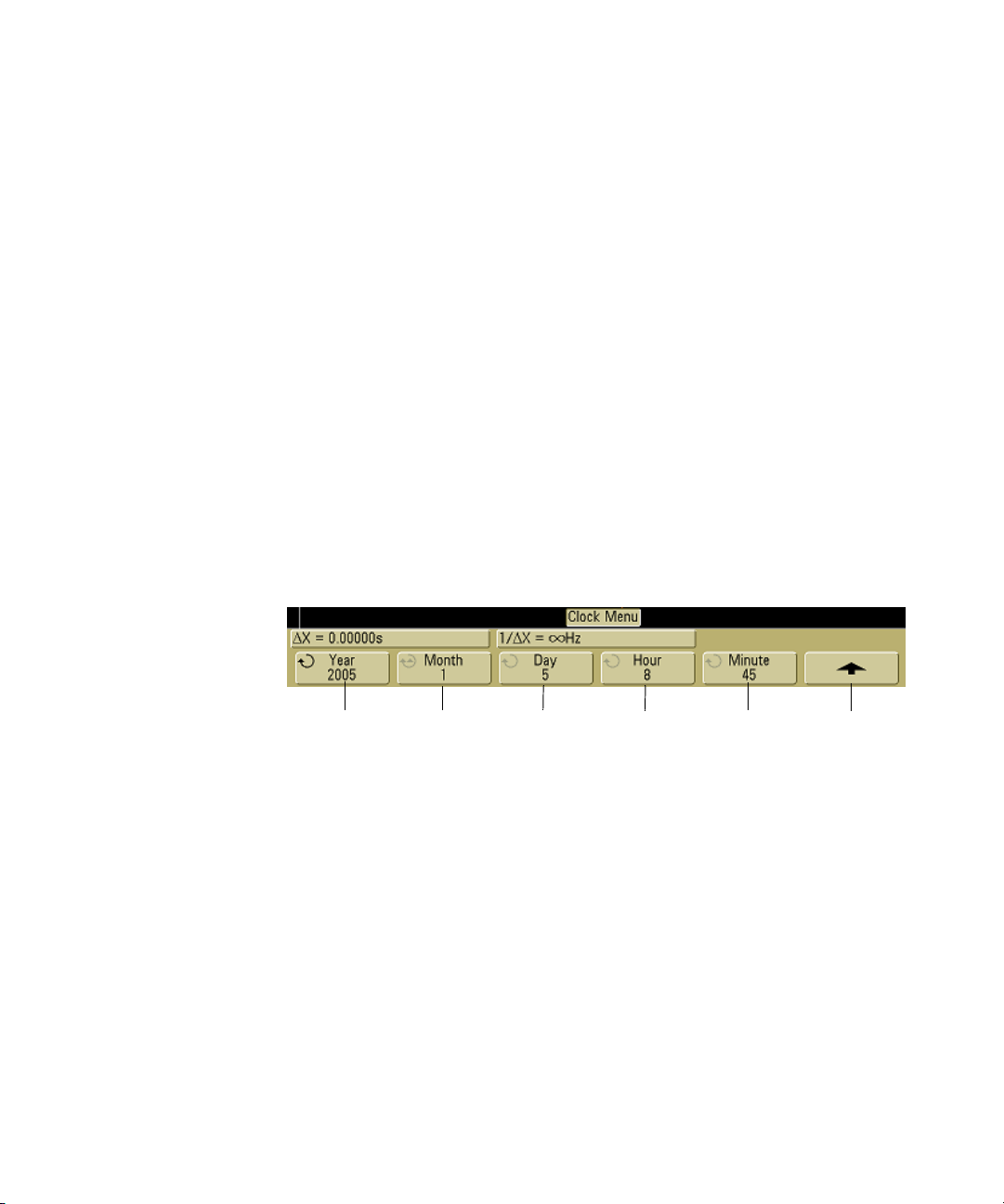
To print the display
You can print the complete display, including the status line
and softkeys, to a USB printer or to a USB mass storage device
by pressing the Quick Print key. You can stop printing by
pressing the Cancel Print softkey.
To set up your printer, press Utility&Print Config.
For more information on printing, see “To configure
printing” on page 282.
To set the clock
The Clock menu lets you set the current date and time of day
(24-hour format). This time/date stamp will appear on hardcopy
prints and directory information on the USB mass storage
device.
To set the date and time, or to view the current date and time:
1 Press Utility&Options&Clock.
Front-Panel Controls 2
Year set Month set Return to
2 Press the Ye ar , Month, Day, Hour or Minute softkey and rotate
the Entry knob to set to the desired number.
The hours are shown in the 24-hour format. So 1:00 PM is hour
13.
The real-time clock only allows selection of valid dates. If a day
is selected and the month or year is changed so the day is
invalid, the day is automatically adjusted.
6000 Series Oscilloscope User’s Guide 95
Day set Hour set Minute set
previous menu
Page 96
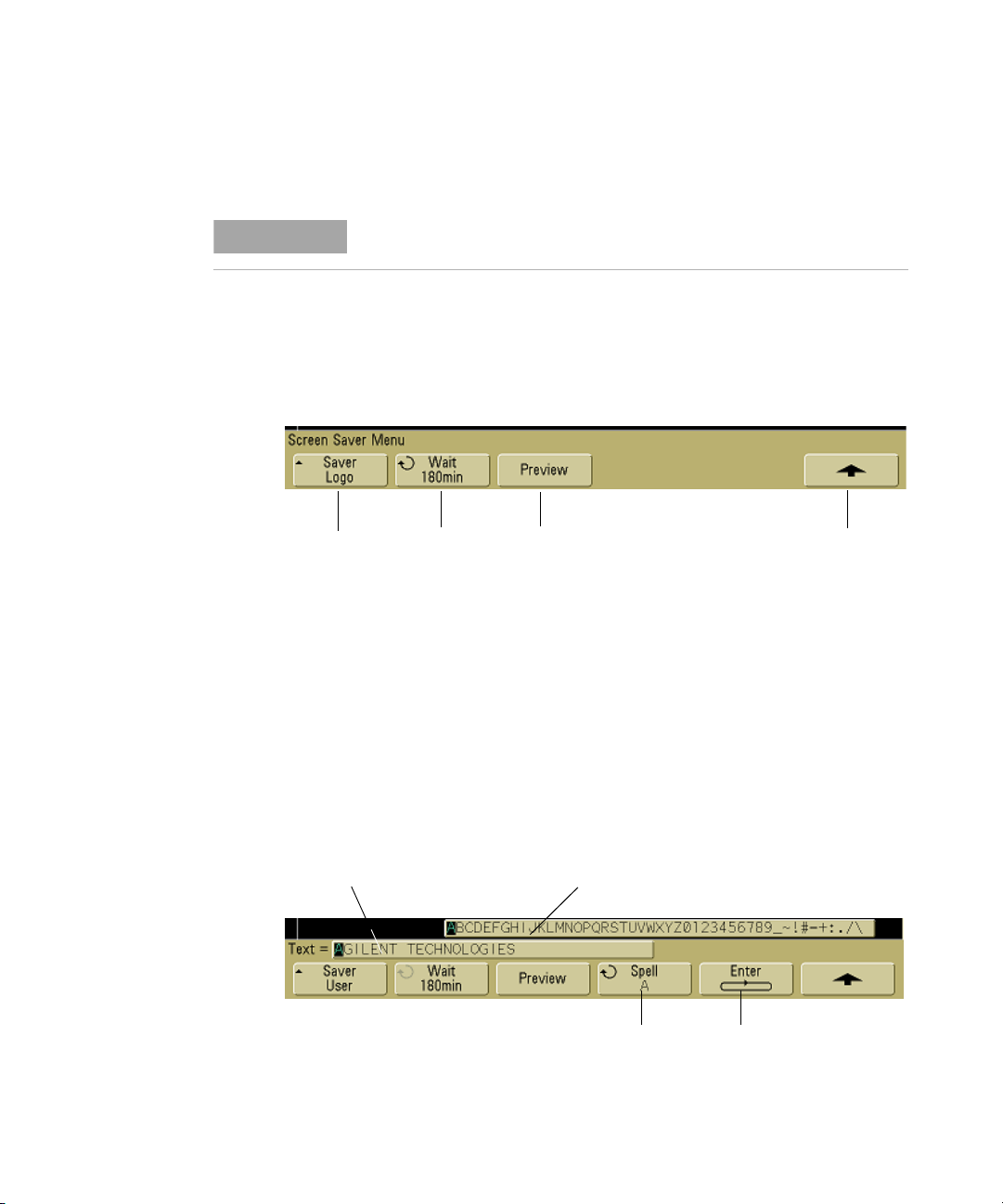
2 Front-Panel Controls
To set up the screen saver
NOTE
Screen saver
image
The Screen Saver is disabled on 6000L models.
The oscilloscope can be configured to turn on a display screen
saver when the oscilloscope has been idle for a specified length
of time.
1 Press Utility&Options&Preferences&Screen Saver to display the
screen saver menu.
Screen saver
time delay
Preview
Return to
previous menu
2 Press the Saver softkey to select the screen saver type.
The screen saver can be set to Off, to display any of the
images shown in the list, or can display a user-defined text
string.
If User is selected, press the Spell softkey to select the first
character of the text string. Use the Entry knob to choose a
character. Then press the Enter softkey to advance to the next
character and repeat the process. The resultant string is
displayed in the "Text =" line above the softkeys.
User-defined
text string
List of characters displayed
when Entry knob is turned
Select
characters
Advance to next
character
96 6000 Series Oscilloscope User’s Guide
Page 97

3 Turn the Entry knob to select the number of minutes to wait
before the selected screen saver activates.
When you turn the Entry knob, the number of minutes is
displayed in the Wait softkey. The default time is 180 minutes
(3 hours).
4 Press the Preview softkey to preview the screen saver you
have selected with the Saver softkey.
5 To view the normal display after the screen saver has started,
press any key or turn any knob.
To set the waveform expansion reference point
• Press Utility&Options&Preferences&Expand and select Ground or
Center.
When you change a channel's volts/division setting, the
waveform display can be set to expand (or compress) about the
signal ground level or the center of the display.
Expand About Ground The displayed waveform will expand
about the position of the channel's ground. This is the default
setting. The ground level of the signal is identified by the
position of the ground level ( ) icon at the far-left side of the
display. The ground level will not move when you adjust the
vertical sensitivity (volts/division) control.
Front-Panel Controls 2
If the ground level is off screen, the waveform will expand about
the top or bottom edge of the screen based on where the ground
is off screen.
Expand About Center The displayed waveform will expand
about the center of the display.
6000 Series Oscilloscope User’s Guide 97
Page 98
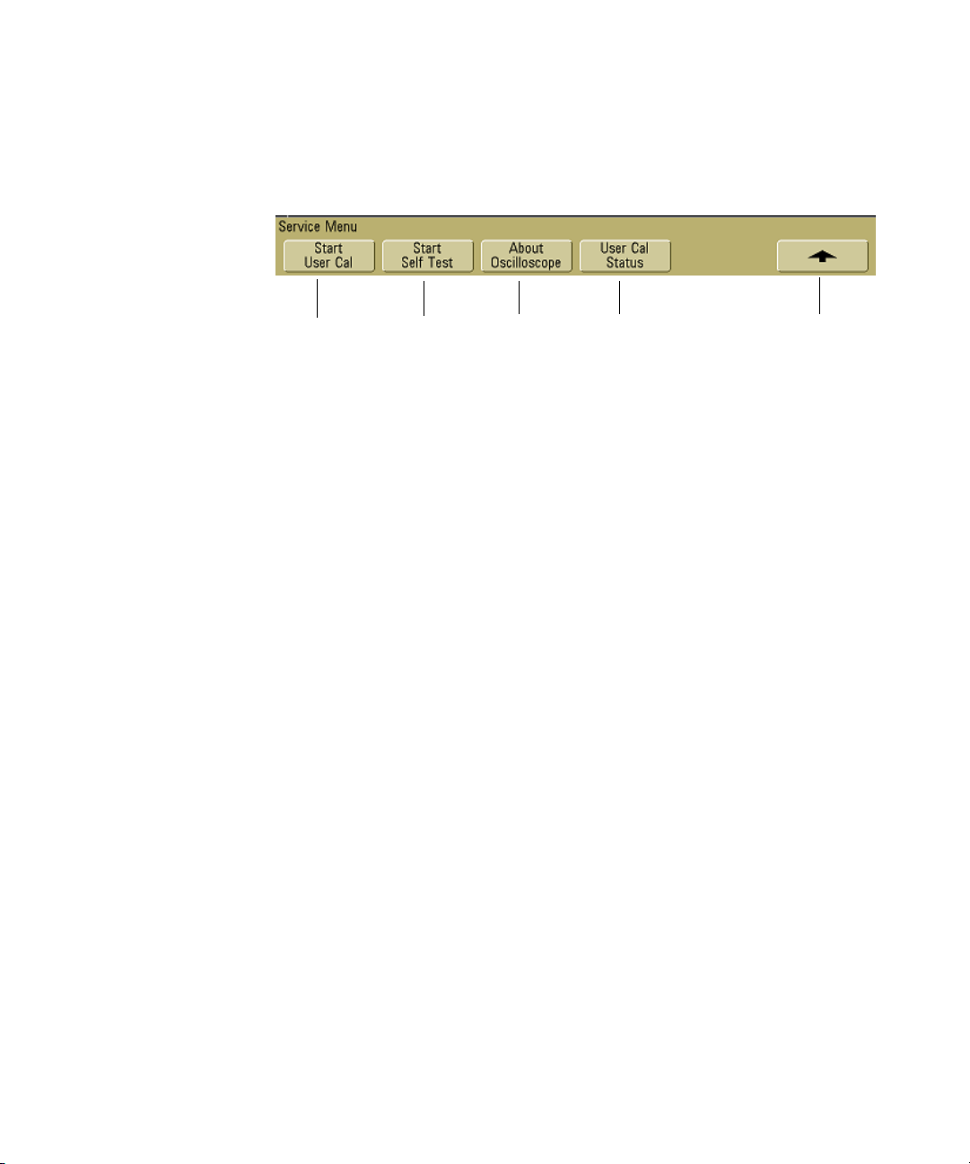
2 Front-Panel Controls
To perform service functions
• Press the Utility&Service to display the service menu.
Start
User Cal
User Calibration
Start
Self Test
About
Oscilloscope
User Cal
status
Return to
previous menu
The Service Menu lets you:
• Perform User Cal on the oscilloscope.
• View User Cal status.
• Perform instrument Self Test.
• View information about your oscilloscope model number,
code revision information, and User Cal status.
Perform user-calibration:
• Each year or after 2000 hours of operation.
• If the ambient temperature is >10° C from the calibration
temperature.
• If you want to maximize the measurement accuracy.
The amount of use, environmental conditions, and experience
with other instruments help determine if you need shorter User
Cal intervals.
User Cal performs an internal self-alignment routine to
optimize the signal path in the oscilloscope. The routine uses
internally generated signals to optimize circuits that affect
channel sensitivity, offset, and trigger parameters. Disconnect
all inputs and allow the oscilloscope to warm up before
performing this procedure.
98 6000 Series Oscilloscope User’s Guide
Page 99
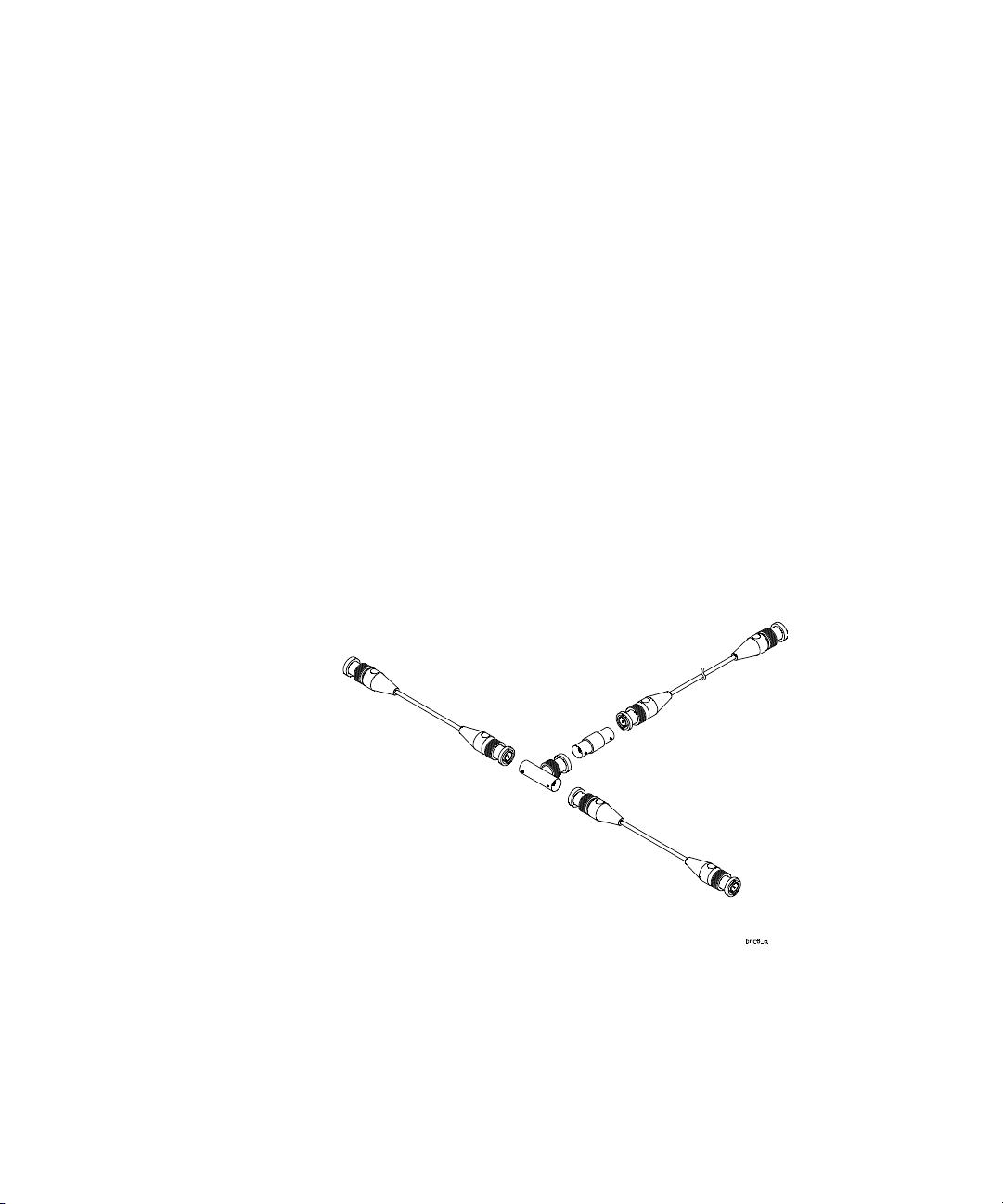
To Channel 1
Front-Panel Controls 2
Performing User Cal will invalidate your Certificate of
Calibration. If NIST (National Institute of Standards and
Technology) traceability is required, perform the Performance
Verification procedure in the Agilent 6000 Series Oscilloscopes
Service Guide using traceable sources.
To perform User Cal
1 Set the rear-panel CALIBRATION switch to UNPROTECTED.
2 Connect short (12 inch maximum) equal length cables to each
analog channel’s BNC connector on the front of the
oscilloscope. You will need two equal-length cables for a
2-channel oscilloscope or four equal-length cables for a
4-channel oscilloscope.
Use 50Ω RG58AU or equivalent BNC cables when performing
User Cal.
For a 2-channel oscilloscope, connect a BNC tee to the equal
length cables. Then connect a BNC(f)-to-BNC(f) (also called a
barrel connector) to the tee as shown below.
Longer cable
to TRIG OUT
To Channel 2
Figure 5 User Calibration cable for 2-channel oscilloscope
6000 Series Oscilloscope User’s Guide 99
Page 100
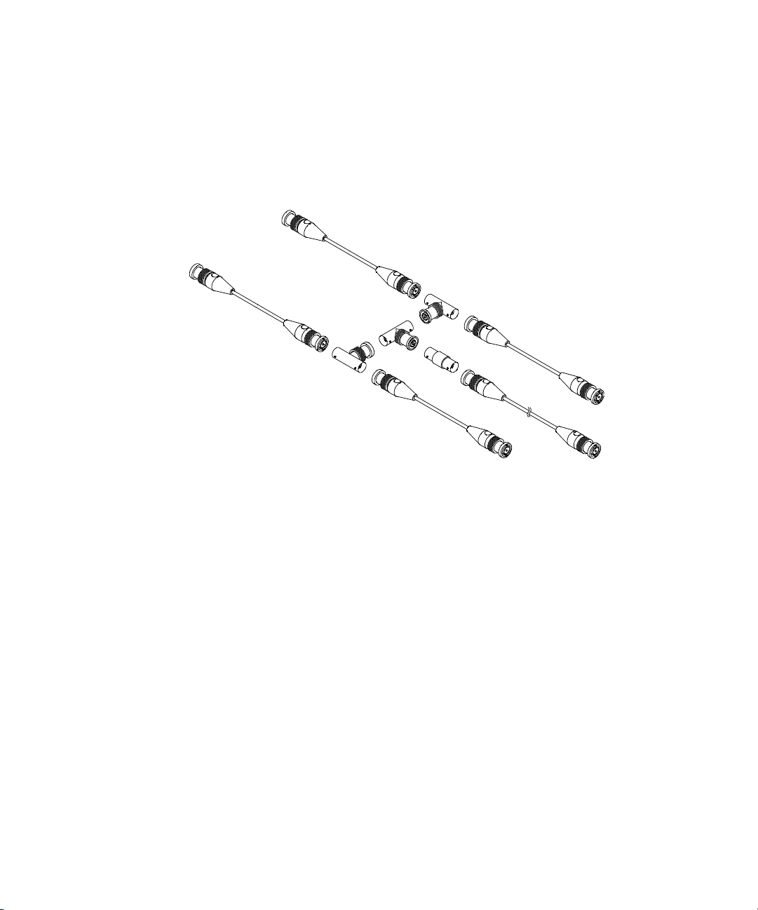
2 Front-Panel Controls
To Channel 2
To Channel 1
For a 4-channel oscilloscope, connect BNC tees to the
equal-length cables as shown below. Then connect a
BNC(f)-to-BNC(f) (barrel connector) to the tee as shown
below.
To Channel 3
Longer cable
To Channel 4
to TRIG OUT
Figure 6 User Calibration cable for 4-channel oscilloscope
1 Connect a BNC cable (40 inches maximum) from the TRIG
OUT connector on the rear panel to the BNC barrel
connector.
2 Press the Utility key, then press the Service softkey.
3 Begin the Self Cal by pressing the Start User Cal softkey.
4 When the User Cal is completed, set the rear-panel
CALIBRATION switch to PROTECTED.
User Cal Status
Pressing Utility&Service&User Cal Status displays the summary
results of the previous User Cal, and the status of probe
calibrations for probes that can be calibrated. Note that passive
100 6000 Series Oscilloscope User’s Guide
 Loading...