

Page 1
Keysight DDR Setup
Assistant
User’s Guide
Page 2

Notices
CAUTION
WARNING
© Keysight Technologies 2013-2014
No part of this manual may be reproduced in
any form or by any means (includ ing electronic storage and retrieval or translation
into a foreign language) without prior agreement and written consent from Keysight
Technologies as governed by United States
and international copyright laws.
Software Release
06.00.0000
Edition
August 2014
Available in electronic format only
Keysight Technologies
1900 Garden of the Gods Road
Colorado Springs, CO 80907 USA
Warranty
THE MATERIAL CONTAINED IN THIS
DOCUMENT IS PROVIDED "AS IS," AND IS
SUBJECT TO BEING CHANGED, WITHOUT
NOTICE, IN FUTURE EDITIONS. FURTHER,
TO THE MAXIMUM EXTENT PERMITTED BY
APPLICABLE LAW, KEYSIGHT DISCLAIMS
ALL WARRANTIES, EITHER EXPRESS OR
IMPLIED WITH REGARD TO THIS MANUAL
AND ANY INFORMATION CONTAINED
HEREIN, INCLUDING BUT NOT LIMITED TO
THE IMPLIED WARRANTIES OF
MERCHANTABILITY AND FITNESS FOR A
PARTICULAR PURPOSE. KEYSIGHT SHALL
NOT BE LIABLE FOR ERRORS OR FOR
INCIDENTAL OR CONSEQUENTIAL
DAMAGES IN CONNECTION WITH THE
FURNISHING, USE, OR PERFORMANCE OF
THIS DOCUMENT OR ANY INFORMATION
CONTAINED HEREIN. SHOULD KEYSIGHT
AND THE USER HAVE A SEPARATE WRITTEN
AGREEMENT WITH WARRANTY TERMS
COVERING THE MATERIAL IN THIS
DOCUMENT THAT CONFLICT WITH THESE
TERMS, THE WARRANTY TERMS IN THE
SEPARATE AGREEMENT WILL CONTROL.
Technology Licenses
The hardware and/or software described in
this document are furnished under a license
and may be used or copied only in accordance with the terms of such license.
52.227-14 (June 1987) or DFAR
252.227-7015 (b)(2) (November 1995), as
applicable in any technical data.
Safety Notices
A CAUTION notice denotes a hazard. It
calls attention to an operating procedure, practice, or the like that, if not
correctly performed or adhered to,
could result in d amage to the prod uct
or loss of important data. Do not proceed beyond a CAUTION notice until
the indicated conditions are fully
understood and met.
A WARNING notice denotes a hazard.
It calls attention to an operating procedure, practice, or the like that, if not
correctly performed or adhered to,
could result in personal injury or
death. Do not proceed beyond a
WARNING notice until the indicated
conditions are fully understood and
met.
Restricted Rights Legend
If software is for use in the performance of a
U.S. Government prime contract or subcontract, Software is delivered and licensed as
"Commercial computer software" as defined
in DFAR 252.227-7014 (June 1995), or as a
"commercial item" as defined in FAR
2.101(a) or as "Restricted computer software" as defined in FAR 52.227-19 (June
1987) or any equivalent agency regulation or
contract clause. Use, duplication or disclosure of Software is subject to Keysight Technologies’ standard commercial license
terms, and non-DOD Departments and
Agencies of the U.S. Government will receive
no greater than Restricted Rights as defined
in FAR 52.227-19(c)(1-2) (June 1987). U.S.
Government users will receive no greater
than Limited Rights as defined in FAR
2 DDR Setup Assistant User’s Guide
Page 3

Safety Summary
CAUTION
WARNING
General Do not use this product in any manner not specified by the manufacturer. The protective features of
The following general safety precautions must be observed during all phases of operation of this
instrument. Failure to comply with these precautions or with specific warnings or operating
instructions in the product manuals violates safety standards of design, manufacture, and intended
use of the instrument. Keysight Technologies assumes no liability for the customer's failure to comply
with these requirements. Product manuals are provided with your instrument on CD-ROM and/or in
printed form. Printed manuals are an option for many products. Manuals may also be available on
the Web. Go to www.keysight.com and type in your product number in the Search field at the top of
the page.
this product may be impaired if it is used in a manner not specified in the operation instructions.
Before Applying
Power
Ground the
Instrument
Fuses See the user's guide or operator's manual for information about line-fuse replacement. Some
Do Not Operate in
an Explosive
Atmosphere
Do Not Remove the
Instrument Cover
Cleaning Clean the outside of the instrument with a soft, lint-free, slightly dampened cloth. Do not use
Do Not Modify the
Instrument
Verify that all safety precautions are taken. Make all connections to the unit before applying power.
Note the instrument's external markings described in “Safety Symbols”.
If your product is provided with a grounding type power plug, the instrument chassis and cover must
be connected to an electrical ground to minimize shock hazard. The ground pin must be firmly
connected to an electrical ground (safety ground) terminal at the power outlet. Any interruption of
the protective (grounding) conductor or disconnection of the protective earth terminal will cause a
potential shock hazard that could result in personal injury.
instruments contain an internal fuse, which is not user accessible.
Do not operate the instrument in the presence of flammable gases or fumes.
Only qualified, service-trained personnel who are aware of the hazards involved should remove
instrument covers. Always disconnect the power cable and any external circuits before removing the
instrument cover.
detergent or chemical solvents.
Do not install substitute parts or perform any unauthorized modification to the product. Return the
product to an Keysight Sales and Service Office for service and repair to ensure that safety features
are maintained.
In Case of Damage Instruments that appear damaged or defective should be made inoperative and secured against
unintended operation until they can be repaired by qualified service personnel.
A CAUTION notice denotes a hazard. It calls attention to an operating procedure, practice,
or the like that, if not correctly performed or adhered to, could result in damage to the
product or loss of important data. Do not proceed beyond a CAUTION notice until the
indicated conditions are fully understood and met.
A WARNING notice denotes a hazard. It calls attention to an operating procedure,
practice, or the like that, if not correctly performed or adhered to, could result in
personal injury or death. Do not proceed beyond a WARNING notice until the indicated
conditions are fully understood and met.
DDR Setup Assistant User’s Guide 3
Page 4
Safety Symbols
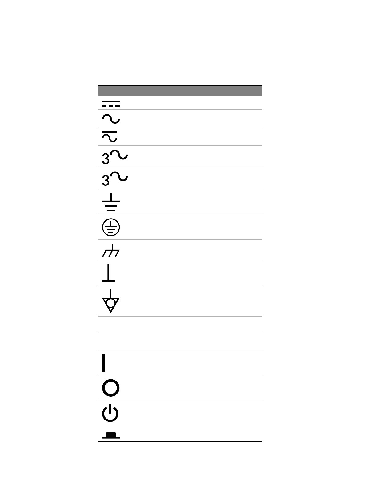
Table 1 Safety Symbol
Symbol Description
Direct current
Alternating current
Both direct and alternating current
Three phase alternating current
Three phase alternating current
Earth ground terminal
Protective earth ground terminal
Frame or chassis ground terminal
N Neutral conductor on permanently
L Line conductor on permanently installed
Terminal is at earth potential
Equipotentiality
installed equipment
equipment
On (mains supply)
Off (mains supply)
Standby (mains supply). The instrument is
not completely disconnected from the
mains supply when the power switch is in
the standby position
In position of a bi-stable push switch
4 DDR Setup Assistant User’s Guide
Page 5

Symbol Description
Out position of a bi-stable push switch
Equipment protected throughout by
DOUBLE INSULATION or REINFORCED
INSULATION
Caution, refer to accompanying
documentation
Caution, risk of electric shock
Do not apply around or remove from
HAZARDOUS LIVE conductors
Application around and removal from
HAZARDOUS LIVE conductors is
permitted
Caution, hot surface
Ionizing radiation
CAT I IEC Measurement Category I
CAT II Measurement Category II
CAT III Measurement Category III
CAT IV Measurement Category IV
DDR Setup Assistant User’s Guide 5
Page 6
Compliance and Environmental Information
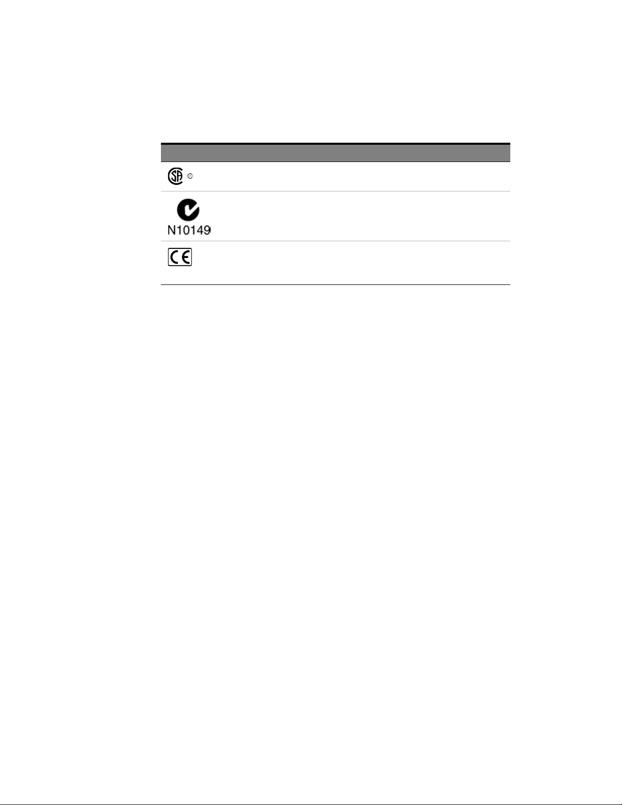
Table 2 Compliance and Environmental Information
Safety Symbol Description
CSA is the Canadian certification mark to demonstrate compliance with the Safety
requirements.
The C-tick mark is a registered trademark of the Spectrum Management
Agency of Australia. This signifies compliance with the Australia EMC
Framework regulations under the terms of the Radio Communication Act
of 1992.
CE compliance marking to the EU Safety and EMC Directives.
ISM GRP-1A classification accord ing to the international EMC stand ard.
ICES/NMB-001 compliance marking to the Canadian EMC standard.
6 DDR Setup Assistant User’s Guide
Page 7
DDR Setup Assistant—At a Glance
The DDR Setup Assistant is a wizard-like application that helps you set up your logic analyzer
properly for DDR/LPDDR data capture and analysis.
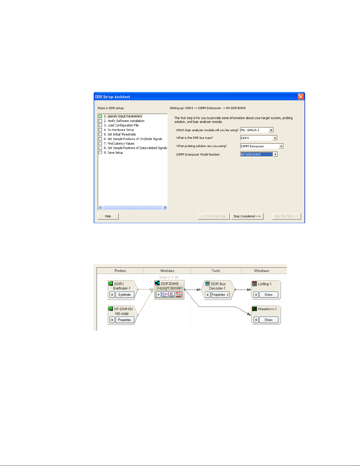
Once you have completed the set up steps using the DDR Setup Assistant, the Keysight Logic and
Protocol Analyzer application will have the appropriate Probes, Modules, Tools, and Windows set up,
similar to those shown in the example Overview tab below.
Typically, the resulting Overview tab will contain:
• DDR3 Eyefinder — used to set up the appropriate sample positions for capturing DDR data.
• General purpose probe tool — shows how to connect the probe to logic analyzer pods.
• Four-card logic analyzer module (16962A or 16960A) or U4154A/B Logic Analyzer module.
• DDR Bus Decoder — decodes the captured data.
• Listing window — to display decoded data.
• Optional Waveform window — to display state or timing waveforms.
• It is best to add Waveform windows immediately after the logic analyzer module because, when
displaying large amounts of waveform data, decoding can slow down the waveform display.
See Also
DDR Setup Assistant User’s Guide 7
"In This Guide" on page 8
Page 8

In This Guide
For an overview and list of features, see: "DDR Setup Assistant—At a Glance" on page 7
First, this guide describes the options for probing DDR devices and the logic analysis system
hardware and software required before you can use the DDR Setup Assistant.
• "Options for Probing DDR Devices" on page 13
• "Before Using the DDR Setup Assistant" on page 29
Next, this guide provides more in-depth information about the steps taken when using the DDR
Setup Assistant:
To use the automated test application, see:
• "Step - Specify Input Parameters" on page 37
• "Step - Verify Software Installation" on page 38
• "Step - Load Configuration File" on page 40
• "Step - Do Hardware Setup" on page 43
• "Step - Set Initial Thresholds" on page 46
• "Step - Set Sample Positions of Clk/CS Signals (only applicable to U4154A/B Logic Analyzer)"
on page 47
• "Step - Set Sample Positions of Command/Addr Signals (only applicable to U4154A/B Logic
Analyzer)" on page 49
• "Step - Set Sample Positions of Ctrl/Addr Signals (not applicable to U4154A/B Logic Analyzer)"
on page 51
• "Step - Find Latency Values" on page 53
• "Step - Set Sample Positions of Data-related Signals (not applicable to U4154A/B logic
analyzer)" on page 64
• "Step - Set Sample Positions of Data Read/Write (only applicable to U4154A/B Logic Analyzer)"
on page 65
• "Step - Save Setup" on page 68
• "Setup Complete" on page 69
Then, there is more in-depth information on using the logic analyzer's automated Thresholds and
Sample Positions set up (also known as normal logic analyzer eye finder), using DDR3 Eyefinder, and
validating DDR setups once you have completed the sampling position set up.
• "Setting Up Thresholds and Sample Positions on DDR Address/Control Signals" on page 71
• "Using DDR3 Eyefinder" on page 79
• "Using Eyescan (for U4154A/B Logic Analyzer Module)" on page 109
• "Validating the DDR Setup" on page 111
Finally, this guide introduces you to the other tools used for capturing and analyzing data from DDR
systems and provides pointers to additional documentation.
• "Capturing Data (Triggering)" on page 113
• "Decoding Captured Data" on page 117
For a printable version of this online help, see: "DDR Setup Assistant Online Help".
See Also
8 DDR Setup Assistant User’s Guide
• DDR probe manuals.
• DDR Bus Decoder Online Help
•DDR Compliance Tool online help.
Page 9

Contents
Safety Summary 3
Compliance and Environmental Information 6
DDR Setup Assistant—At a Glance 7
In This Guide 8
1 Options for Probing DDR Devices
DDR3 DIMM Interposers 14
FS2352 1867 DDR3 DIMM Probe from FuturePlus 15
Nexus DDR3 DIMM Interposer 16
N4835A (FS2351) DDR3 DIMM Interposer (Discontinued) 17
N4821B (FS2350) DDR3 DIMM Interposer (Discontinued) 18
DDR3 SODIMM Interposers 19
FS2354 DDR3 SODIMM Interposer 19
Nexus DDR3 SODIMM Interposer 20
DDR3 BGA Probes 21
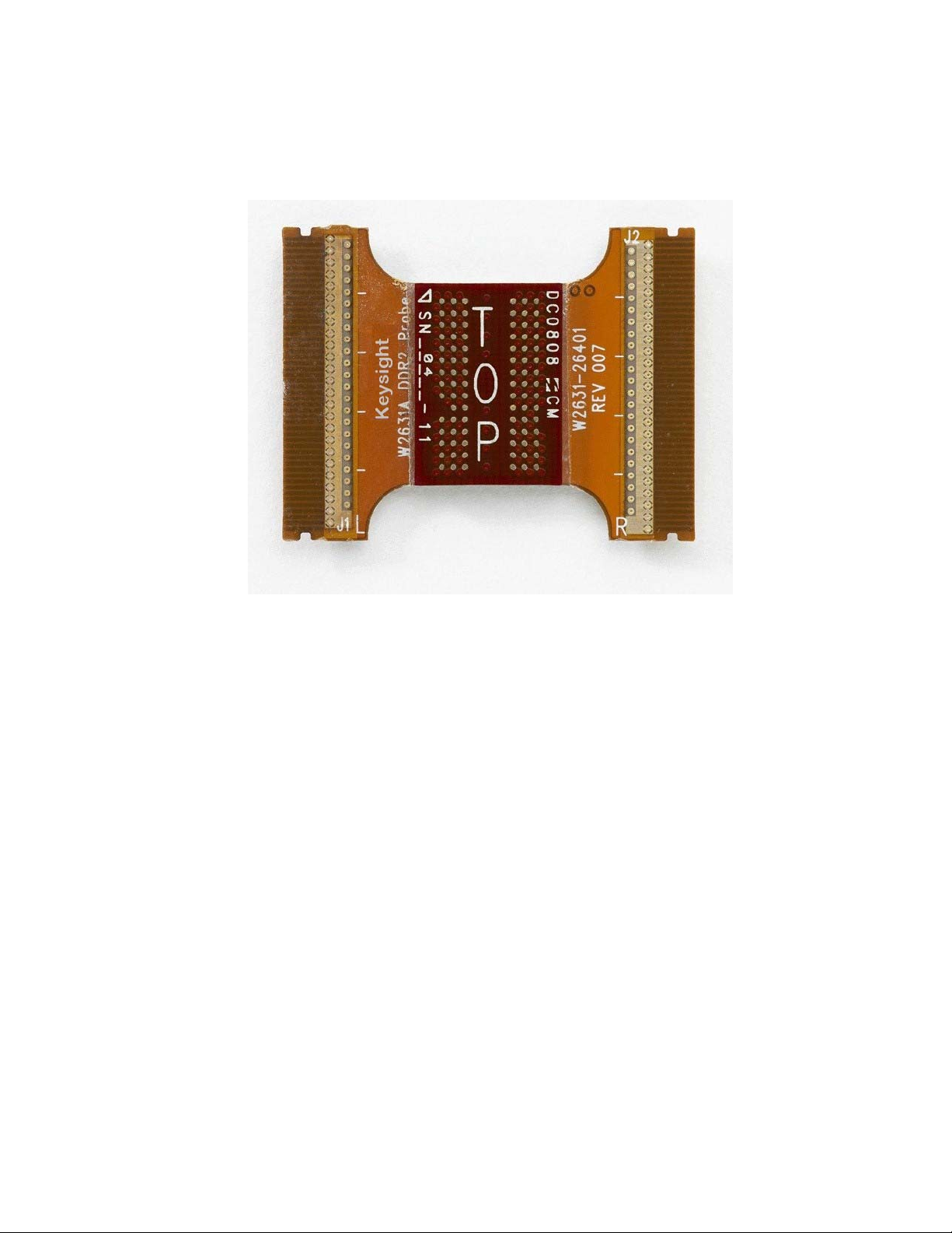
W3633A DDR3 BGA x8 Probe 21
W3631A DDR3 BGA x16 Probe 22
DDR3 Midbus Probes 23
N4834A DDR3 Midbus Probe (Discontinued) 23
DDR2 BGA Probes 24
W2633A/B, W2634A DDR2 BGA x8 Probe 24
W2631A/B, W2632A DDR2 BGA x16 Probe 24
LPDDR BGA Probes 26
W2638A LPDDR BGA x32 Probe 26
W2637A LPDDR BGA x16 Probe 26
Custom Midbus Probing 27
Soft Touch / Soft Touch Pro Embedded Custom Midbus Probing 27
2 Before Using the DDR Setup Assistant
Logic Analysis System Hardware Requirements 30
Installing Required and Optional Software 31
Tuning Your DDR DUT to Make the Best Measurements 32
DDR Setup Assistant User’s Guide 9
Page 10

Contents
Setting Up Read and Write Traffic in the DUT 33
3 Using the DDR Setup Assistant
Starting the DDR Setup Assistant 36
Step - Specify Input Parameters 37
Step - Verify Software Installation 38
Step - Load Configuration File 40
Step - Do Hard ware Setup 43
Step - Set Initial Thresholds 46
Step - Set Sample Positions of Clk/CS Signals (only applicable to U4154A/B Logic
Analyzer) 47
Step - Set Sample Positions of Command/Addr Signals (only applicable to U4154A/B Logic
Analyzer) 49
Step - Set Sample Positions of Ctrl/Addr Signals (not applicable to U4154A/B Logic
Analyzer) 51
If there are problems with finding Ctrl/Addr sample positions 52
Step - Find Latency Values 53
Taking a Mode Register Settings (MRS) Trace 54
Setting Latency Values in DDR Bus Decoder 57
Setting Latency Values in DDR3 Eyefinder 59
Setting Latency Values in Eyescan 60
Step - Set Sample Positions of Data-related Signals (not applicable to U4154A/B logic
analyzer) 64
Step - Set Sample Positions of Data Read/Write (only applicable to U4154A/B Logic
Analyzer) 65
To find and set sample positions for DDR4 Data related signals 66
Step - Save Setup 68
Setup Complete 69
4 Setting Up Thresholds and Sample Positions on DDR Address/Control Signals
Setting Up Thresholds and Sample Positions 72
Solving Problems with Thresholds and Sample Positions Set Up 76
No eye finder or eye scan eyes for Address and Command 76
Clock edges "too close together" error message on Run 76
10 DDR Setup Assistant User’s Guide
Page 11

5 Using DDR3 Eyefinder
Getting Started with DDR3 Eyefinder (for 16962A/16960A) 80
Before Running DDR3 Eyefinder 80
Your First DDR3 Eyefinder Scan (16962A logic analyzers only) 80
Setting Scan Options 91
Setting DDR Bus Specifications 91
Setting Scan Mode 92
Setting Scan Options 93
Performing Scans 97
Setting Sample Positions 98
Adjusting the Display Scale 98
Changing the Time Bucket Scaling and Colors 99
Adjusting the Eye Sensitivity 100
Adjusting Sample Positions 101
Viewing Signal Swing vs. Time 103
Contents
Solving DDR3 Eyefinder Problems 104
If scans stick on Runs in DDR3 Eyefinder 104
If there are no transitions in DDR3 Eyefinder 104
If eyes show tri-stating 104
If eyes are closed 105
If there are multiple eyes 106
If eye scan results are noisy 106
6 Using Eyescan (for U4154A/B Logic Analyzer Module)
7 Validating the DDR Setup
Validating Data in the Trace 112
8 Capturing Data (Triggering)
Recalling DDR Favorite Triggers 114
Triggering on Valid Commands 115
Burst Triggering 116
9 Decoding Captured Data
DDR Bus Decoder 118
DDR Setup Assistant User’s Guide 11
Page 12

Contents
A Setting Data Sample Positions with the 1695x Logic Analyzers
B DDR Glossary
Index
12 DDR Setup Assistant User’s Guide
Page 13

DDR Setup Assistant
User’s Guide
1 Options for Probing DDR De-
vices
There are several different Keysight and third-party options for probing a DDR device under test
(DUT).
DDR3 • “DDR3 DIMM Interposers" on page 14
• “FS2352 1867 DDR3 DIMM Probe from FuturePlus" on page 15
• “Nexus DDR3 DIMM Interposer" on page 16
• “N4835A (FS2351) DDR3 DIMM Interposer (Discontinued)" on page 17
• “N4821B (FS2350) DDR3 DIMM Interposer (Discontinued)" on page 18
• “DDR3 SODIMM Interposers" on page 19:
• “FS2354 DDR3 SODIMM Interposer" on page 19
• “Nexus DDR3 SODIMM Interposer" on page 20
• “DDR3 BGA Probes" on page 21:
• “W3633A DDR3 BGA x8 Probe" on page 21
• “W3631A DDR3 BGA x16 Probe" on page 22
• “DDR3 Midbus Probes" on page 23:
• “N4834A DDR3 Midbus Probe (Discontinued)" on page 23
DDR2 • “DDR2 BGA Probes" on page 24:
• “W2633A/B, W2634A DDR2 BGA x8 Probe" on page 24
• “W2631A/B, W2632A DDR2 BGA x16 Probe" on page 24
LPDDR • “LPDDR BGA Probes" on page 26:
• “W2638A LPDDR BGA x32 Probe" on page 26
• “W2637A LPDDR BGA x16 Probe" on page 26
Custom • “Custom Midbus Probing" on page 27:
• “Soft Touch / Soft Touch Pro Embedded Custom Midbus Probing" on page 27
Page 14
1 Options for Probing DDR Devices
DDR3 DIMM Interposers
• “FS2352 1867 DDR3 DIMM Probe from FuturePlus" on page 15
• “Nexus DDR3 DIMM Interposer" on page 16
• “N4835A (FS2351) DDR3 DIMM Interposer (Discontinued)" on page 17
• “N4821B (FS2350) DDR3 DIMM Interposer (Discontinued)" on page 18
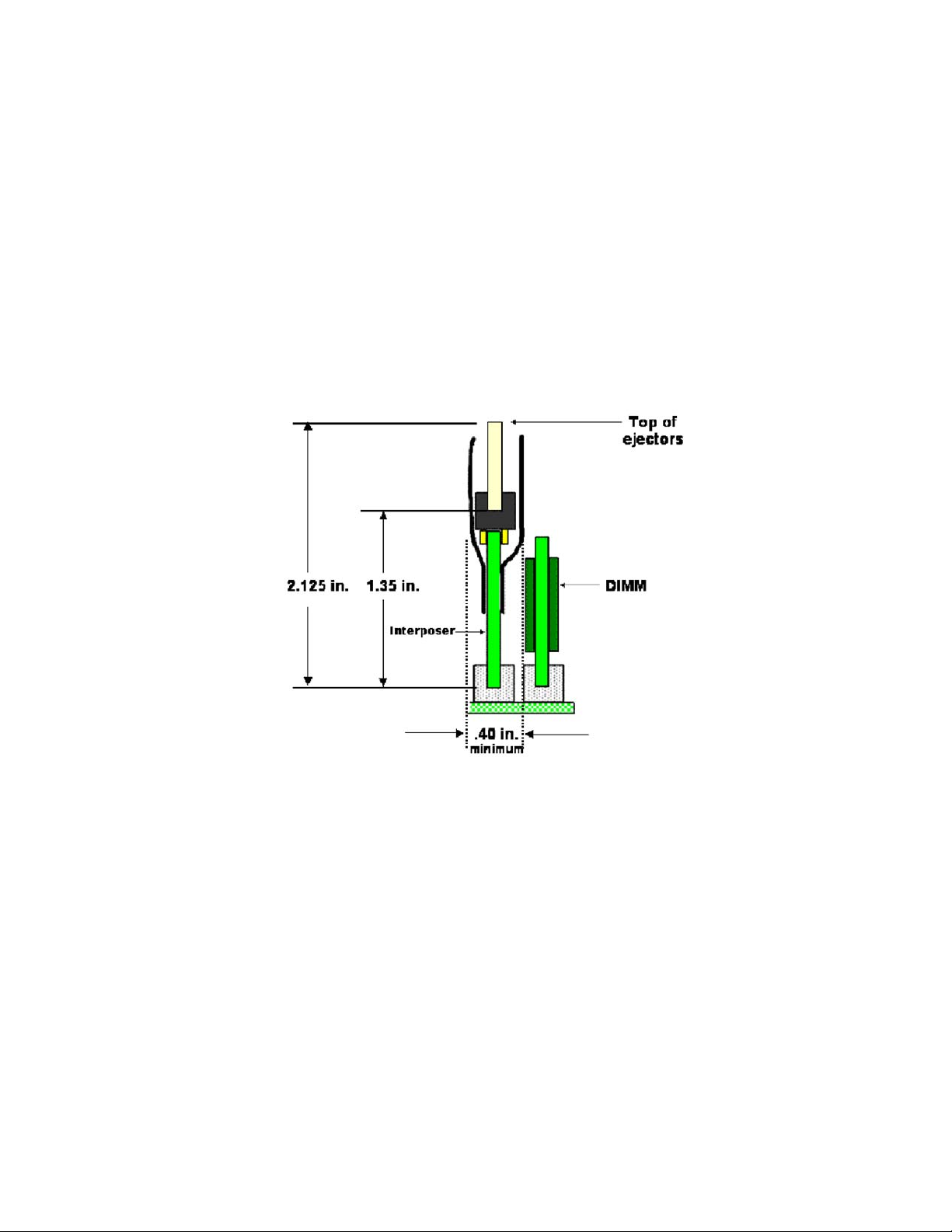
Handling DIMM
Interposers
Handle interposers carefully.
• Provide strain relief for cables.
• Store and ship flat.
Using DIMM
Interposers
14 DDR Setup Assistant User Guide
1 First, make sure that the device under test boots without the interposer.
2 Power down the device under test.
3 Insert interposer into the DIMM socket.
4 Fan headers out on either side of interposer.
5 Insert the DIMM into the interposer.
6 Make connections to the logic analyzer pod cables as shown in the configuration file's
general-purpose probe tool.
Page 15
FS2352 1867 DDR3 DIMM Probe from FuturePlus
Options for Probing DDR Devices 1
Configuration Files
for FS2352
For More
Information
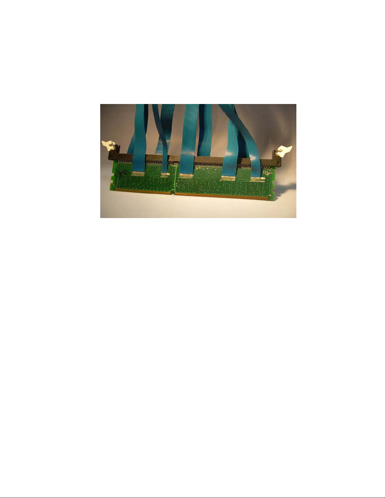
FS2352 1867 DIMM probe from FuturePlus works with 16962A logic analyzer modules only.
The default location for FuturePlus configuration files is: C:\Documents and Settings\All Users\
Shared Documents\Keysight Technologies\Logic Analyzer\Default Configs\FuturePlus
• Search for "FS2352" on the "FuturePlus web site".
DDR Setup Assistant User Guide 15
Page 16
1 Options for Probing DDR Devices
Nexus DDR3 DIMM Interposer
Configuration Files
for Nexus DDR3
DIMM Interposer
For More
Information
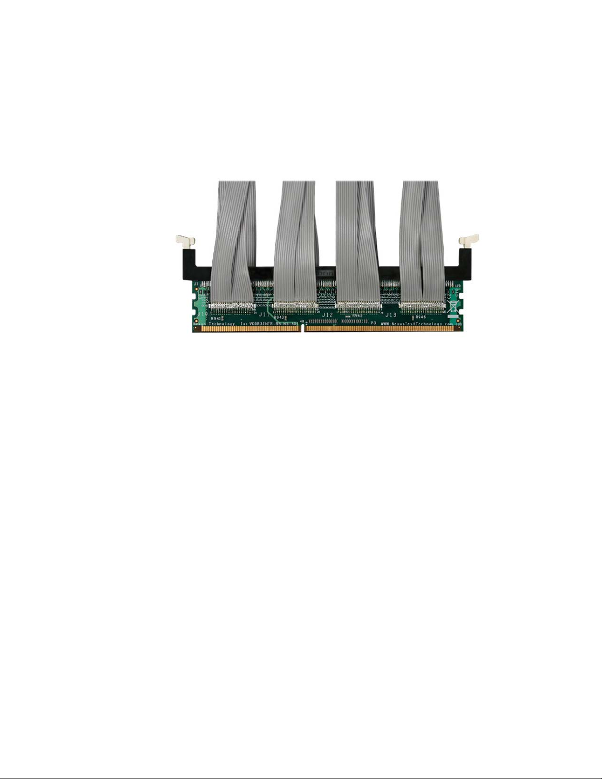
The Nexus DDR3 DIMM interposer works with 16962A logic analyzer modules only.
The default location for Nexux configuration files is: C:\Documents and Settings\All Users\Shared
Documents\Keysight Technologies\Logic Analyzer\Default Configs\Nexus
•See "NT-DDR3DIHS information on the Nexus Technology web site".
16 DDR Setup Assistant User Guide
Page 17
N4835A (FS2351) DDR3 DIMM Interposer (Discontinued)
CAUTION
Options for Probing DDR Devices 1
Configuration File
for N4835A
For More
Information
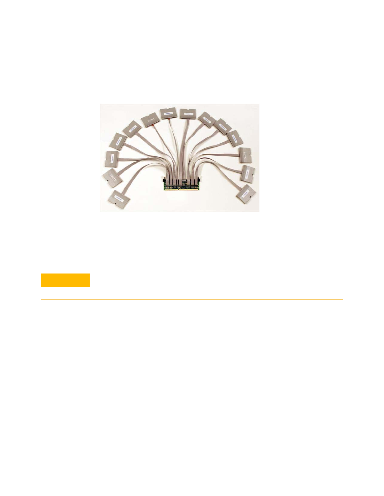
N4835A (FS2351) works with 16960A or 16962A logic analyzer modules.
There is one configuration file for the N4835A DDR3 DIMM interposer at all data rates.
* CK0 is double probed on N4835A. You can run eye finder and eye scan (that is, logic analyzer
Thresholds and Sample Positions set up) on the sample of CK0 that is not used as the actual clock.
Make sure you have the proper N4835A configuration file for the N4835A (FS2351) interposer.
While the pod connections are the same as with the N4821B (FS2350) interposer's 1066/1333
configuration, the signal mapping is not the same!
See "To load a configuration file" (in the online help).
•See Keysight N4835A DDR3 DIMM Interposer Installation Guide which can be found on the
"Keysight web site".
DDR Setup Assistant User Guide 17
Page 18
1 Options for Probing DDR Devices
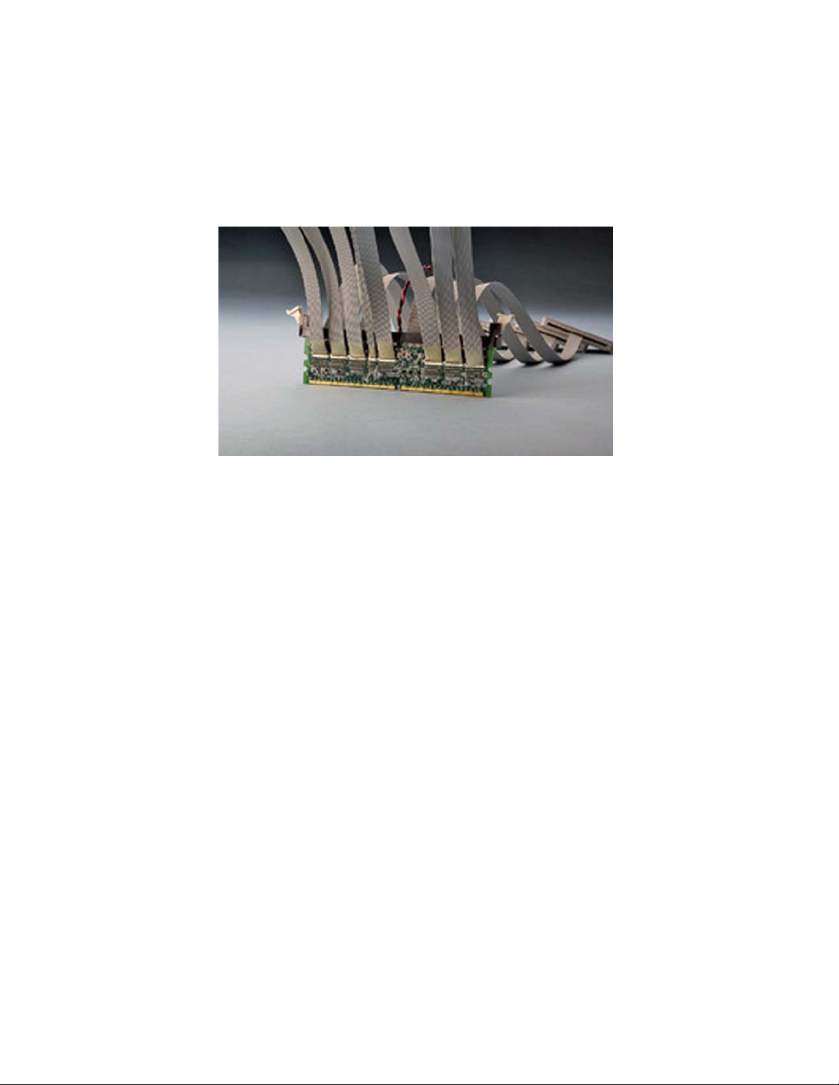
N4821B (FS2350) DDR3 DIMM Interposer (Discontinued)
Configuration Files
for N4821B
For More
Information
N4821B (FS2350) works with 16960A or 16962A logic analyzer modules.
There is one configuration file for the 16962A logic analyzer at all data rates. There are two
configuration files for the 16960A logic analyzer module: one for 800/1600 data rates, and one for
1066/1333 data rates.
See "To load a configuration file" (in the online help).
• Search for "FS2350" on the "FuturePlus web site".
18 DDR Setup Assistant User Guide
Page 19
DDR3 SODIMM Interposers
• “FS2354 DDR3 SODIMM Interposer" on page 19
• “Nexus DDR3 SODIMM Interposer" on page 20
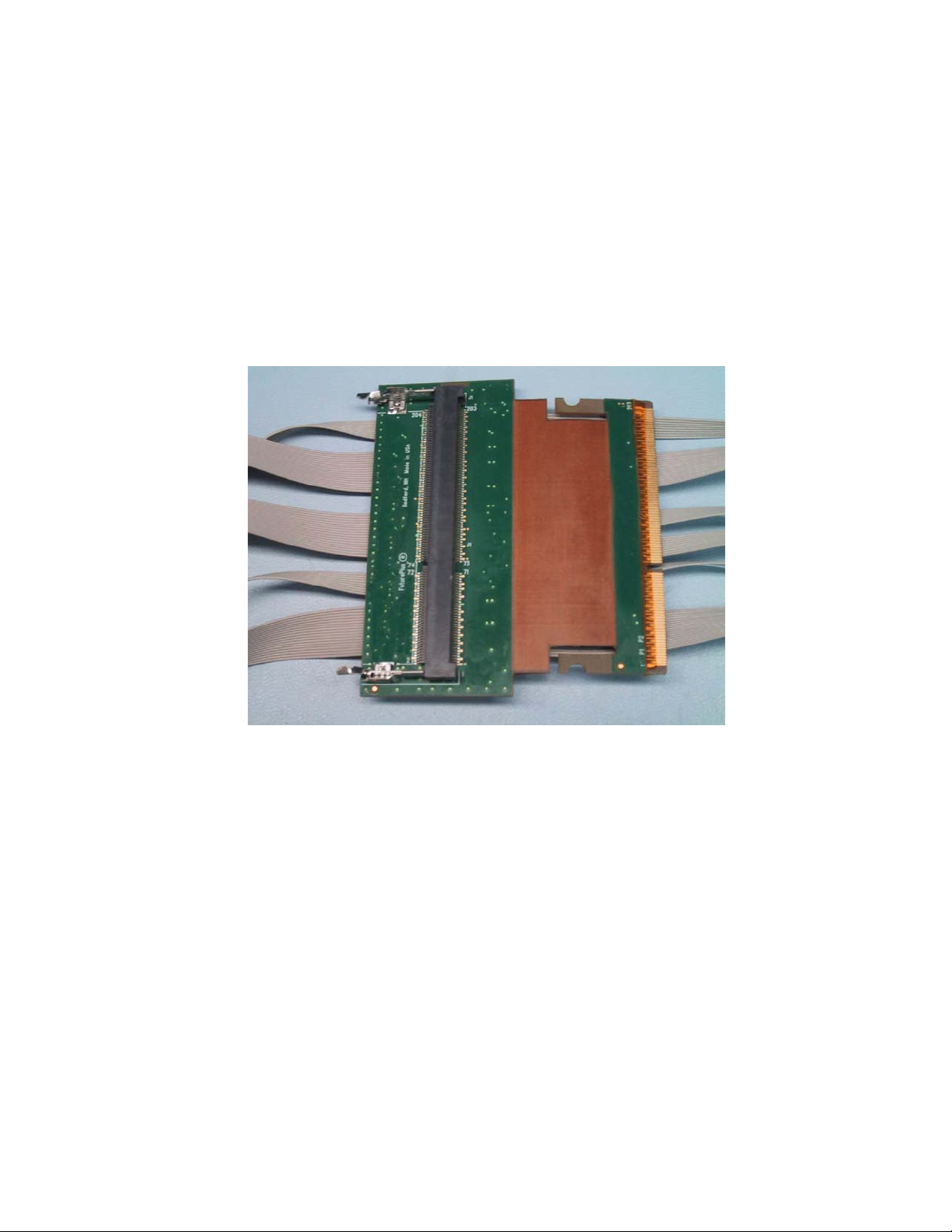
FS2354 DDR3 SODIMM Interposer
Options for Probing DDR Devices 1
FS2354 SODIMM works with 16962A logic analyzer modules only.
Configuration Files
for FS2354
For More
The default location for FuturePlus configuration files is: C:\Documents and Settings\All Users\
Shared Documents\Keysight Technologies\Logic Analyzer\Default Configs\FuturePlus
• Search for "FS2354" on the "FuturePlus web site".
Information
DDR Setup Assistant User Guide 19
Page 20
1 Options for Probing DDR Devices
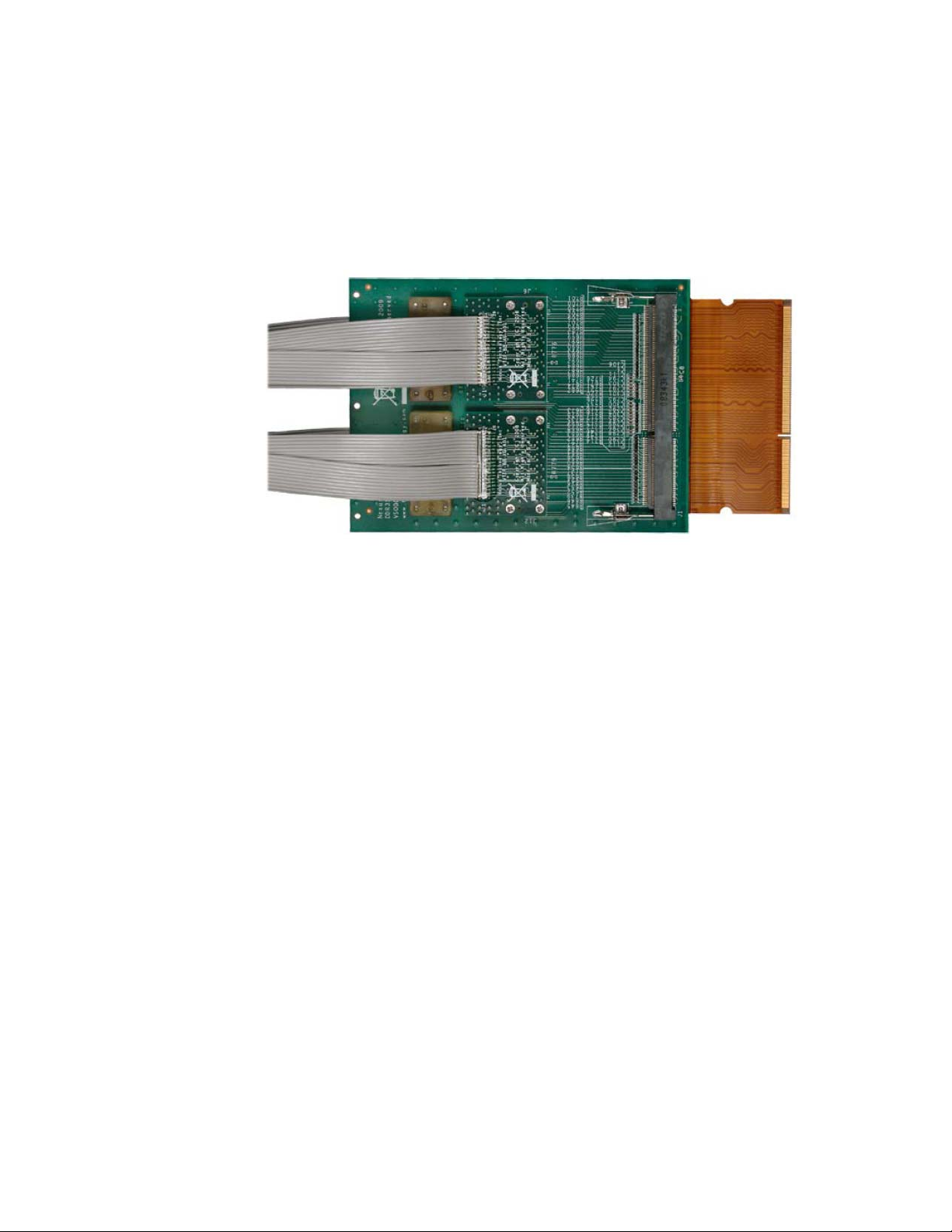
Nexus DDR3 SODIMM Interposer
Configuration Files
for Nexus DDR3
SODIMM
Interposer
For More
Information
Nexus DDR3 SODIMM interposer works with 16962A logic analyzer modules only.
The default location for Nexux configuration files is: C:\Documents and Settings\All Users\Shared
Documents\Keysight Technologies\Logic Analyzer\Default Configs\Nexus
•See "NT-DDR3SOIHS information on the Nexus Technology web site".
20 DDR Setup Assistant User Guide
Page 21
DDR3 BGA Probes
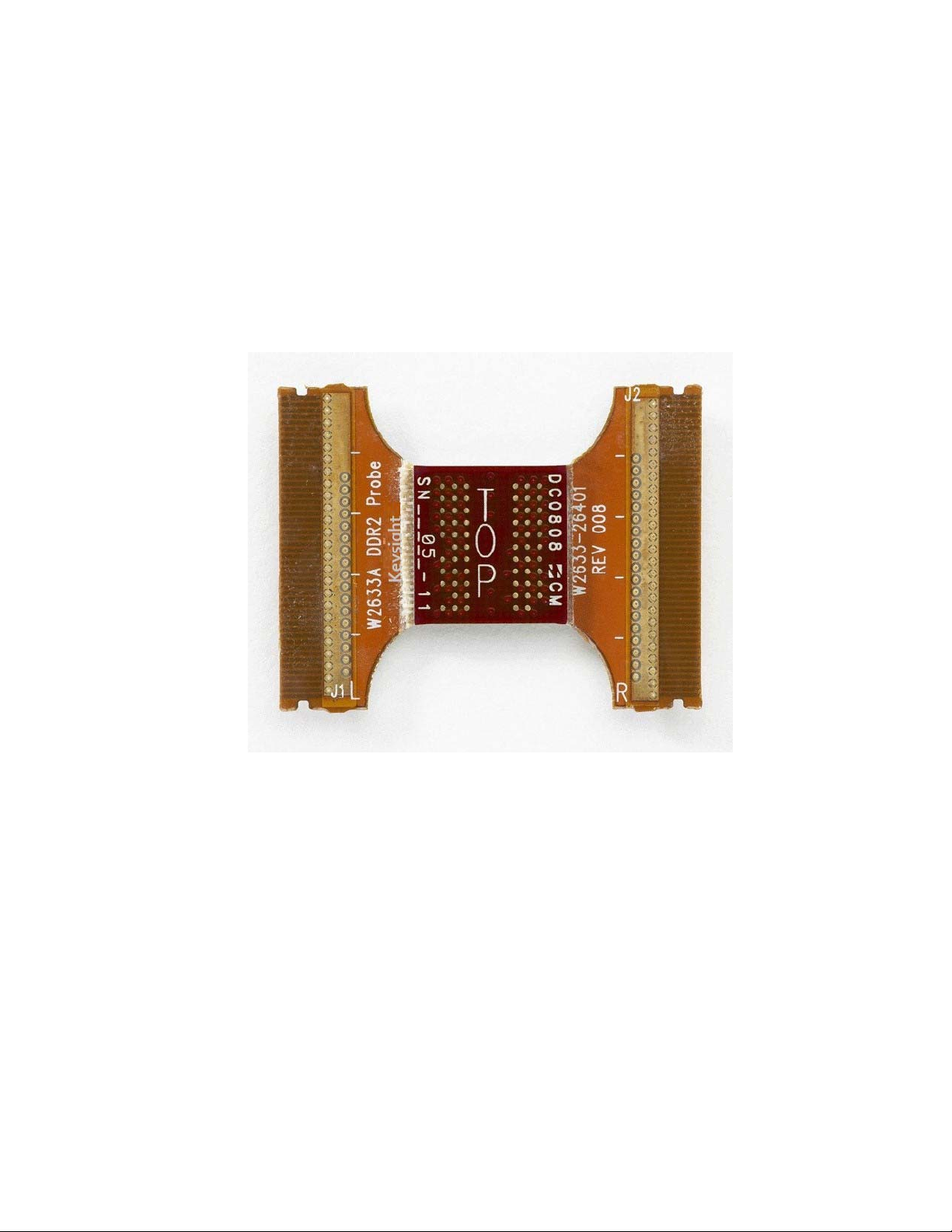
W3633A DDR3 BGA x8 Probe
Options for Probing DDR Devices 1
• “W3633A DDR3 BGA x8 Probe" on page 21
• “W3631A DDR3 BGA x16 Probe" on page 22
The DDR3 BGA probes work with 16950A/B or 16962A logic analyzer modules, and there separate
configuration files for each. There are also separate configuration files for the x8 and x16 probes.
Configuration Files
See "To load a configuration file" (in the online help).
for W3633A Probe
For More
Information, See
DDR Setup Assistant User Guide 21
• Keysight W3630 Series DDR3 DRAM BGA Probes Installation Guide which can be found on the
"Keysight web site".
Page 22
1 Options for Probing DDR Devices
W3631A DDR3 BGA x16 Probe
Configuration Files
for W3631A Probe
For More
Information, See
See "To load a configuration file" (in the online help).
• Keysight W3630 Series DDR3 DRAM BGA Probes Installation Guide which can be found on the
"Keysight web site".
22 DDR Setup Assistant User Guide
Page 23
DDR3 Midbus Probes
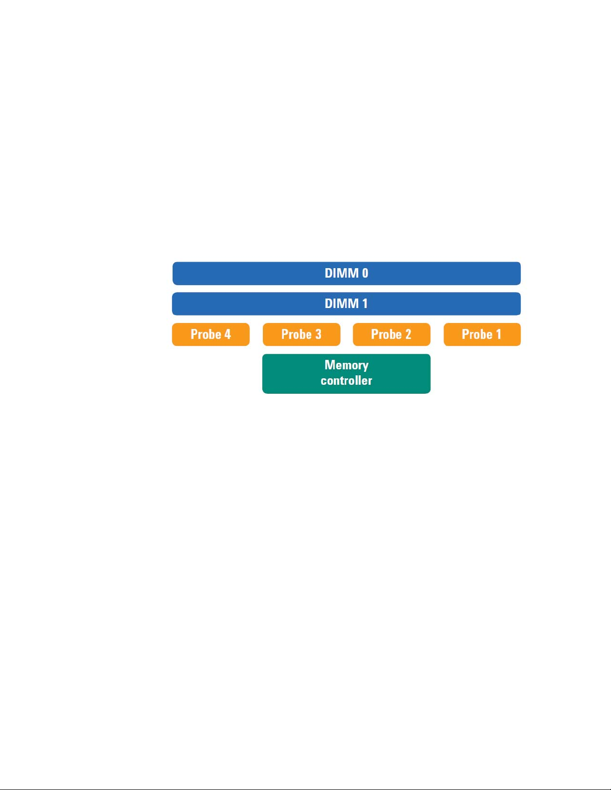
DDR3 midbus probes require special footprints to be designed into the device under test, and they
require double probing. Limited quantities of these probes were available.
• “N4834A DDR3 Midbus Probe (Discontinued)" on page 23
N4834A DDR3 Midbus Probe (Discontinued)
For embedded DDR3 design or validation board design with no constraints on board spaces, the
N4834A double probed soft touch probe can be used for midbus probing. The N4834A comes in sets
of 4 double probed soft touch probes for connection to four footprints on the board.
Options for Probing DDR Devices 1
Configuration Files
for N4834A Probe
For More
Information
The N4834A DDR3 midbus probe works with 16960A or 16962A logic analyzer modules.
See "To load a configuration file" (in the online help).
• Search for "N4834A" on the "Keysight web site".
DDR Setup Assistant User Guide 23
Page 24
1 Options for Probing DDR Devices
DDR2 BGA Probes
• “W2633A/B, W2634A DDR2 BGA x8 Probe" on page 24
• “W2631A/B, W2632A DDR2 BGA x16 Probe" on page 24
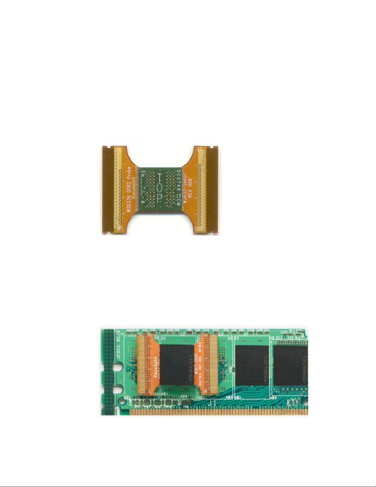
The DDR2 BGA probes work with 16950A/B or 16962A logic analyzer modules, and there separate
configuration files for each. There are also separate configuration files for the x8 and x16 probes.
W2633A/B, W2634A DDR2 BGA x8 Probe
Configuration Files
for W2633A/B,
W2634A Probes
For More
Information, See
W2631A/B, W2632A DDR2 BGA x16 Probe
See "To load a configuration file" (in the online help).
• Keysight W2630 Series DDR2 DRAM BGA Probes Installation Guide which can be found on the
"Keysight web site".
24 DDR Setup Assistant User Guide
Page 25

Options for Probing DDR Devices 1
Configuration Files
for W2631A/B,
W2632A Probes
For More
Information, See
See "To load a configuration file" (in the online help).
• Keysight W2630 Series DDR2 DRAM BGA Probes Installation Guide which can be found on the
"Keysight web site".
DDR Setup Assistant User Guide 25
Page 26
1 Options for Probing DDR Devices
LPDDR BGA Probes
• “W2638A LPDDR BGA x32 Probe" on page 26
• “W2637A LPDDR BGA x16 Probe" on page 26
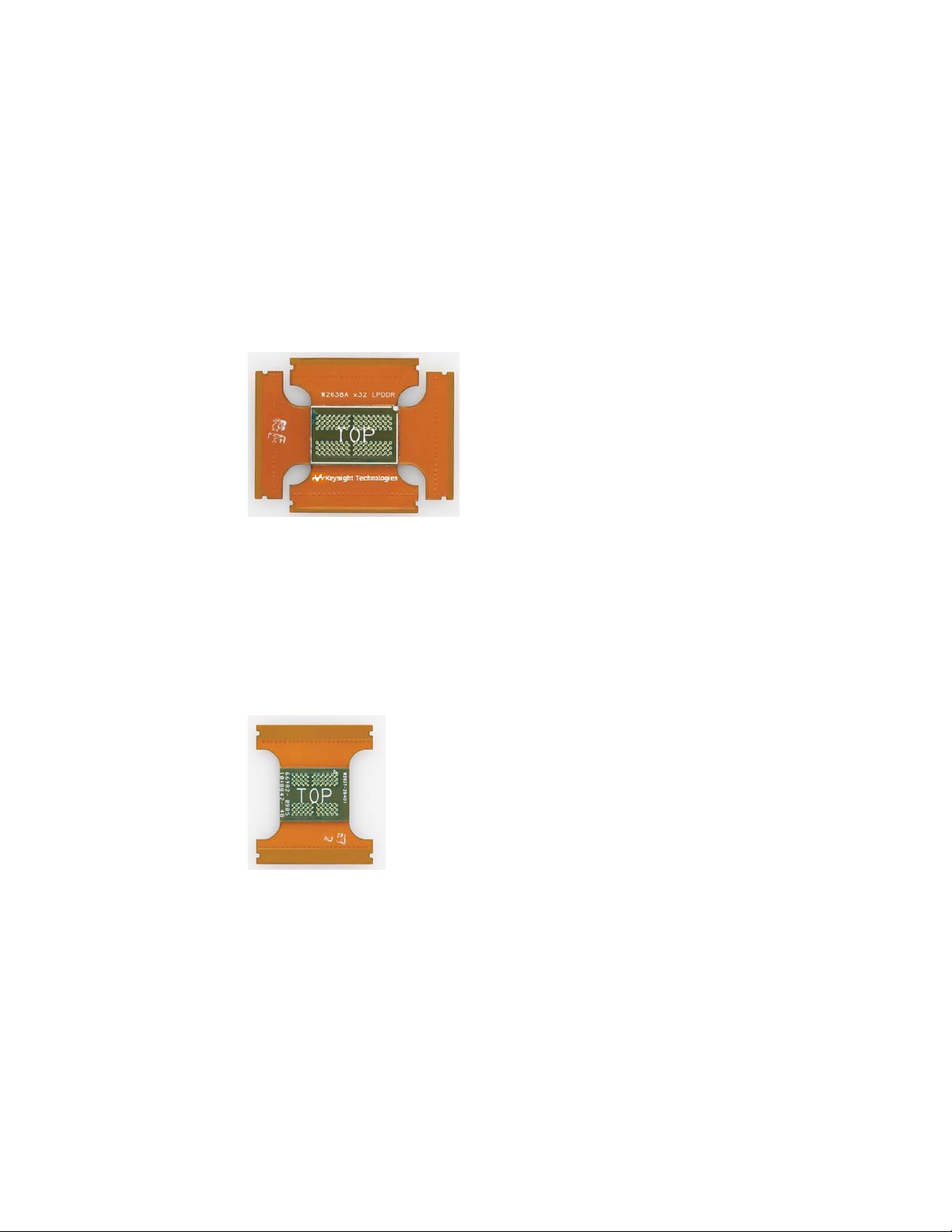
The LPDDR BGA probes work with 16950A/B or 16962A logic analyzer modules, and there separate
configuration files for each.
W2638A LPDDR BGA x32 Probe
Configuration Files
for W2638A Probe
For More
Information, See
W2637A LPDDR BGA x16 Probe
Configuration Files
for W2637A Probe
For More
Information, See
See "To load a configuration file" (in the online help).
• W2637A and W2638A LPDDR BGA Probes / W2639A Oscilloscope Adapter Board User's Guide
which can be found on the "Keysight web site".
See "To load a configuration file" (in the online help).
• W2637A and W2638A LPDDR BGA Probes / W2639A Oscilloscope Adapter Board User's Guide
which can be found on the "Keysight web site".
26 DDR Setup Assistant User Guide
Page 27

Custom Midbus Probing
For custom midbus probing, you can design Soft Touch or Soft Touch Pro footprints into your device
under test and route signals to the footprint pads.
• “Soft Touch / Soft Touch Pro Embedded Custom Midbus Probing" on page 27
Soft Touch / Soft Touch Pro Embedded Custom Midbus Probing
You can design Soft Touch or Soft Touch Pro footprints into your device under test (DUT) and route
signals to the footprint pads. Because this type of probing is custom, DUT designs are unique.
However, there are some common things to consider.
Because DDR data reads and writes occur at different times relative to the bus (and sampling) clock,
you must use the logic analyzer's dual sample sampling clock mode (see "Dual Sample Sampling
Clock Mode" (in the online help)). This affects how signals are probed and mapped to logic analyzer
pods.
Other considerations for embedded Soft Touch footprints for 16962A or 16960A logic analyzers:
• The CK0, Address, and Control bits should be placed on one Soft Touch footprint. This is a
requirement for DDR3 Eyefinder. Also, you must connect the address and control signals to a
different logic analyzer module than the data /strobe signals. Solutions for DDR logic analysis
require a module minimum of two logic analyzer modules.
• The CK0 signal must be probed differentially and must be connected to the pod 1 clock of the
clocking module (this is the second card up from the bottom of the mainframe).
• The CKE0 signal should be connected to the clock input on pod 2 of the master module. When
setting up the state sampling clock options in the logic analyzer, select:
• CKE0 – latched high for capture out of reset.
• CKE0 – enabled high as clock qualifier.
• Make sure there are no signal stubs!
• Optional: consider routing a copy of the CS#0 signal to the Pod 4 clock input on the master
module.
• The minimum signals required for DDR logic analysis tools are:
• CK0, COMMAND, CS#, Data_W, Data_R, CKE*, BA, ADDR, RowADDR, and ColADDR.
• Custom triggers may require additional signals.
Options for Probing DDR Devices 1
Configuration Files
for Soft Touch
Probes
For More
Information, See
DDR Setup Assistant User Guide 27
With custom probing, you will likely have custom configuration files. Be sure to include a
general-purpose probe tool in your Overview configuration to describe how logic analyzer pod
connectors should be connected to the probes.
To simplify the procedure of custom configuration file creation, Keysight provides the DDR/LPDDR
Custom Configuration Creator tool. The tool ensures that all the layout information needed by
DDR/LPDDR Decoder is included in the created configuration file. This tool is a part of the Keysight
DDR Setup Assistant and Eyefinder software package. Therefore, the tool is available only after you
install this package. To know more about this tool, refer to its online help that gets installed with this
tool’s software.
• Keysight Technologies E5400-Pro Series Soft Touch Connectorless Probes User's Guide which
can be found on the "Keysight web site".
• Keysight Technologies Soft Touch Connectorless Probes User's Guide which can be found on the
"Keysight web site".
Page 28

1 Options for Probing DDR Devices
28 DDR Setup Assistant User Guide
Page 29

DDR Setup Assistant
User’s Guide
2 Before Using the DDR Setup
Assistant
Logic Analysis System Hardware Requirements / 30
Installing Required and Optional Software / 31
Tuning Your DDR DUT to Make the Best Measurements / 32
Setting Up Read and Write Traffic in the DUT / 33
Once you have chosen a solution for probing your DDR device, you must make sure you have the
required logic analysis system hardware and software. This includes any necessary probe to logic
analyzer cable adapters.
There are also some things you can do to prepare your DDR device under test in order to make the
best measurements.
Page 30

2 Before Using the DDR Setup Assistant
Logic Analysis System Hardware Requirements
To capture DDR Command, Address, Control, and Data signals, a four-card, 68-channel per card,
logic analyzer card set with sufficient state analysis speed is required. The 16962A and 16960A logic
analyzer cards meet these requirements.
A six-slot logic analysis system frame is required for the four-card logic analyzer. The 16902B logic
analysis system frame meets the requirement.
Besides these, you can also use the 136 channel U4154A/B Logic Analyzer module installed in the
Keysight AXIe chassis to capture DDR signals.
30 DDR Setup Assistant User Guide
Page 31

Before Using the DDR Setup Assistant 2
NOTE
Installing Required and Optional Software
While the DDR Setup Assistant works with the Keysight Logic Analyzer application on a computer
remotely connected to logic analyzer hardware, we recommend you run the DDR Setup Assistant
on the logic analysis system that contains the logic analyzer hardware. This is because the logic
analyzer's automated Thresholds and Sample Positions set up (also known as logic analyzer eye
finder) and DDR3 Eyefinder run faster in this configuration.
You can use the Windows operating system's Remote Desktop Connection feature to log into the
logic analysis system that has the logic analyzer hardware. The Remote Desktop Connection
provides good performance.
Before you begin using the DDR Setup Assistant, make sure the required software (and any desired
optional software) is installed.
This software can be downloaded from the Keysight web site at:
"www.keysight.com/find/la-sw-download"
Required Software The following software is required in order to use the DDR Setup Assistant:
• Keysight Logic Analyzer Application Software, version 04.00 or higher.
• DDR2 and DDR3 Bus Decoder (B4621B, requires a license), version 04.00 or higher. This software
decodes the captured signals, showing commands, cycle types, etc. DDR configuration files are
included with the bus decoder and many of them assume the bus decoder is present.
• DDR3 Eyefinder, version 04.00 or higher. This software is necessary to set sample positions for
Data signals.
• If you have a third-party (non-Keysight) probe, there may be third-party software that is also
required.
Optional DDR
Tools
The following software is optional but is useful for DDR analysis:
• DDR2/3 Protocol Compliance and Analysis Tool (B4622B, requires a license), version 04.00 or
higher. This is an automated test application that evaluates captured LPDDR/LPDDR2 and
DDR/DDR2/DDR3 data against a set of user-defined limits to help you validate that a memory
system is operating properly. When used with the U4154A/B module, it can evaluate LPDDR3 and
DDR4 data as well.
DDR Setup Assistant User Guide 31
Page 32

2 Before Using the DDR Setup Assistant
Tuning Your DDR DUT to Make the Best Measurements
There are a couple things you can do to prepare your DDR device under test for making
measurements:
• Turn off data scrambling.
• Turn off power management (for initial measurements).
32 DDR Setup Assistant User Guide
Page 33

Setting Up Read and Write Traffic in the DUT
READ and WRITE traffic in the DDR device under test (DUT) is required for both Read and Write
signal sampling set up. For example:
• Random pattern data tests:
• Memtest 86 test #7.
• Memory test with alternating patterns:
• Memtest 86 test #5.
• Video clips.
Before Using the DDR Setup Assistant 2
DDR Setup Assistant User Guide 33
Page 34

2 Before Using the DDR Setup Assistant
34 DDR Setup Assistant User Guide
Page 35

DDR Setup Assistant
User’s Guide
3 Using the DDR Setup Assis-
tant
Starting the DDR Setup Assistant / 36
Step - Specify Input Parameters / 37
Step - Verify Software Installation / 38
Step - Load Configuration File / 40
Step - Do Hardware Setup / 43
Step - Set Initial Thresholds / 46
Step - Set Sample Positions of Clk/CS Signals (only applicable to U4154A/B Logic Analyzer) / 47
Step - Set Sample Positions of Command/Addr Signals (only applicable to U4154A/B Logic Analyzer) /
49
Step - Set Sample Positions of Ctrl/Addr Signals (not applicable to U4154A/B Logic Analyzer) / 51
Step - Find Latency Values / 53
Step - Set Sample Positions of Data-related Signals (not applicable to U4154A/B logic analyzer) / 64
Step - Set Sample Positions of Data Read/Write (only applicable to U4154A/B Logic Analyzer) / 65
Step - Save Setup / 68
Setup Complete / 69
Page 36

3 Using the DDR Setup Assistant
NOTE
Starting the DDR Setup Assistant
While the DDR Setup Assistant works with the Keysight Logic Analyzer application on a computer
remotely connected to logic analyzer hardware, we recommend you run the DDR Setup Assistant
on the logic analysis system that contains the logic analyzer hardware. This is because the logic
analyzer's automated Thresholds and Sample Positions set up (also known as logic analyzer eye
finder) and DDR3 Eyefinder run faster in this configuration.
You can use the Windows operating system's Remote Desktop Connection feature to log into the
logic analysis system that has the logic analyzer hardware. The Remote Desktop Connection
provides good performance.
1 After installing the DDR Setup Assistant, double-click the DDR Setup Assistant icon on your
desktop to start the DDR Setup Assistant.
The DDR Setup Assistant automatically starts the Keysight Logic Analyzer application if it is not
already started.
36 DDR Setup Assistant User Guide
Page 37
Step - Specify Input Parameters
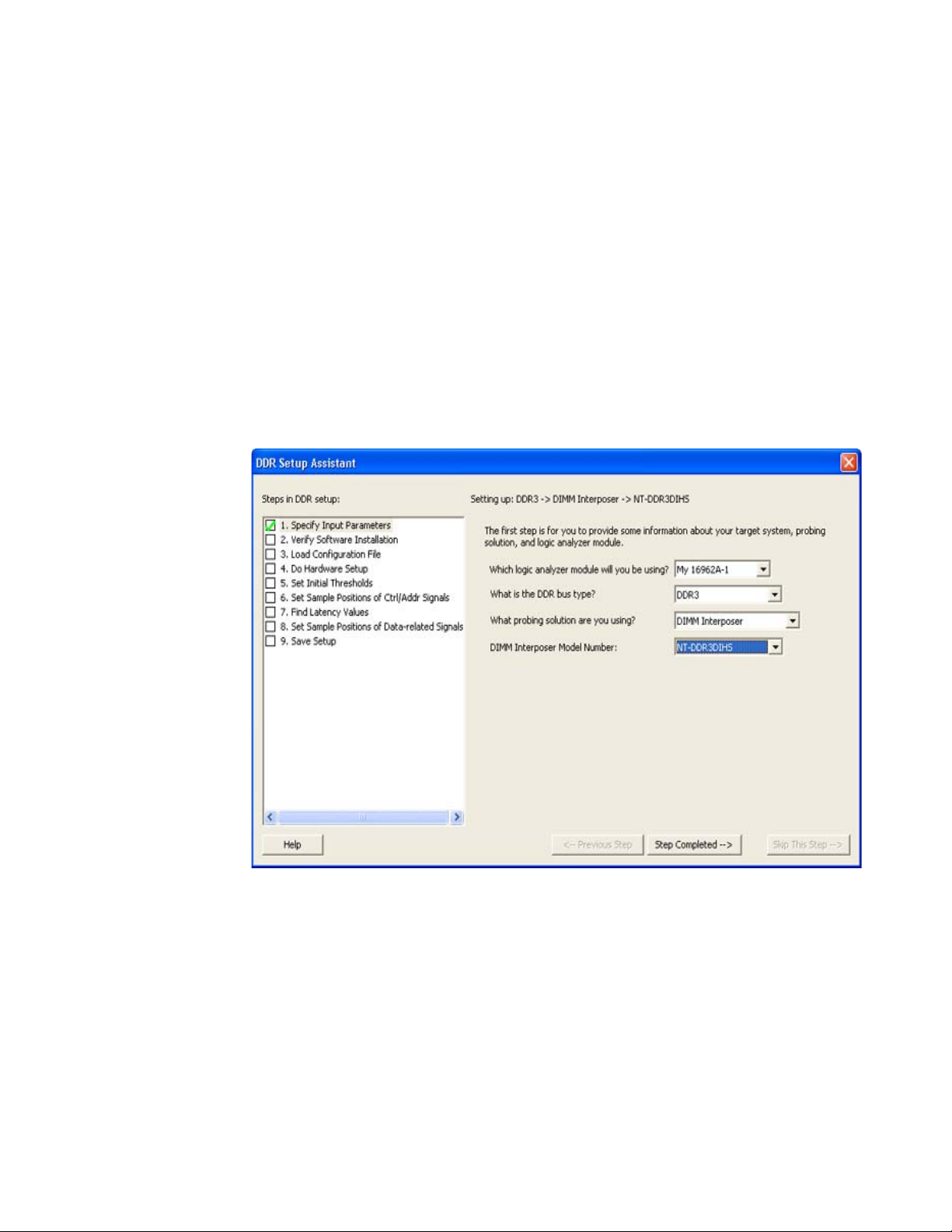
In this step, you give the DDR Setup Assistant relevant information about your DDR test setup.
1 Select the name of the logic analyzer module that will be used to capture DDR signals.
2 Select the DDR bus type.
3 Specify your probing solution (see “Options for Probing DDR Devices" on page 13).
Depending on the probing solution you select, you may have additional input parameters to
specify. For example:
• When you select the BGA probing solution, you have an additional selection for your DRAM type
and data width.
• When you select the DIMM Interposer probing solution, there is an additional selection for the
model number.
• When you select the Softtouch probing solution, there are no other input parameters to specify.
Using the DDR Setup Assistant 3
4 When you are finished selecting input parameters, click Step Completed -->.
The selections you make in this step identify your setup for the automated DDR Setup Assistant
actions that follow.
Next • “Step - Verify Software Installation" on page 38
DDR Setup Assistant User Guide 37
Page 38
3 Using the DDR Setup Assistant
Step - Verify Software Installation
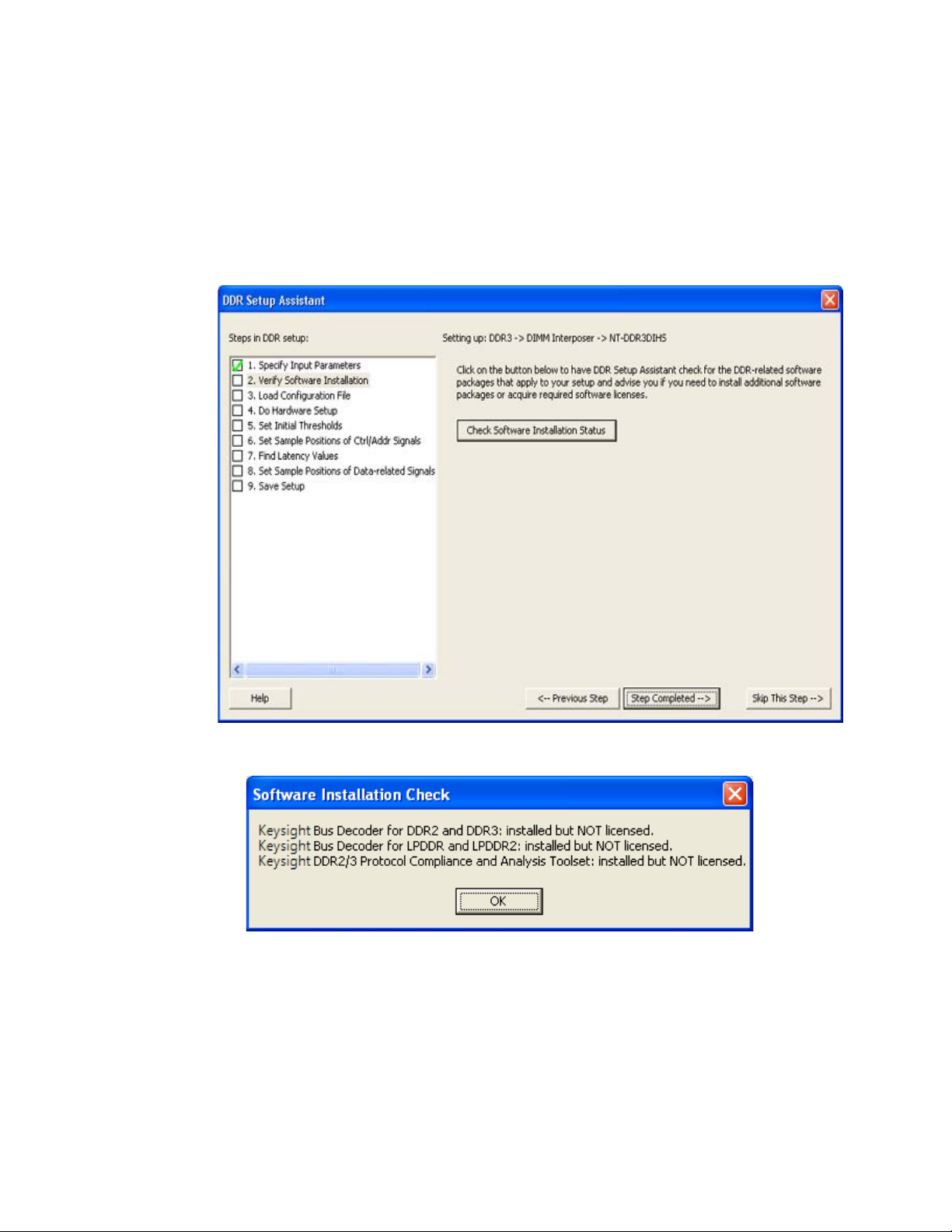
In this step, the DDR Setup Assistant checks to see if the required and optional DDR analysis
software has been installed.
1Click Check Software Installation Status.
When the check is complete, an information with the software installation status appears.
2 If you need to install software:
a Close the DDR Setup Assistant.
b Close the Keysight Logic Analyzer application.
c Install the software (see “Installing Required and Optional Software" on page 31).
d Restart the Keysight Logic Analyzer application.
e Restart the DDR Setup Assistant.
f Continue with the DDR set up steps.
3Click Step Completed -->.
38 DDR Setup Assistant User Guide
Page 39

Next • “Step - Load Configuration File" on page 40
Using the DDR Setup Assistant 3
DDR Setup Assistant User Guide 39
Page 40
3 Using the DDR Setup Assistant
NOTE
Step - Load Configuration File
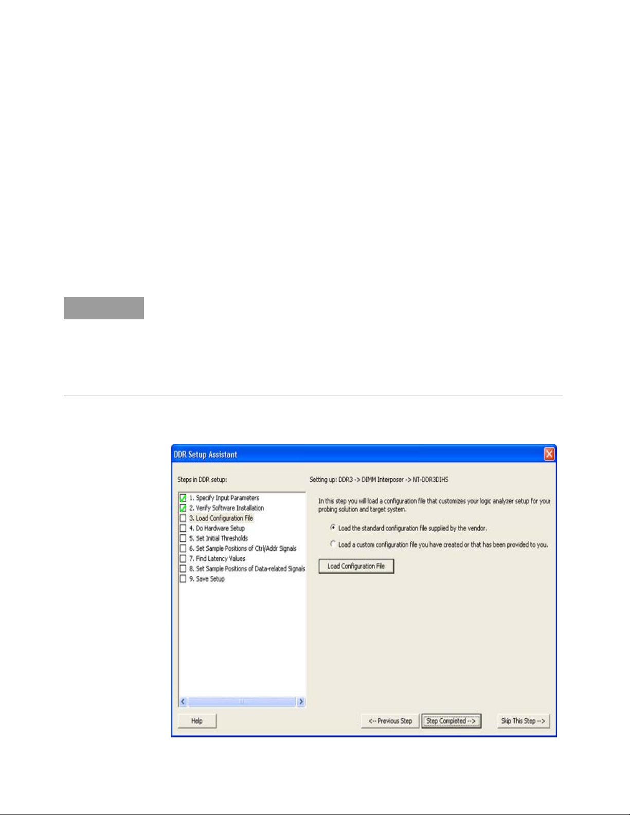
In this step, the DDR Setup Assistant loads the selected XML configuration file.
1 Select whether you want to load an Keysight-supplied standard configuration file (if you are using
an Keysight probing solution) or a custom configuration file (if you are using a custom probing
solution).
If you select to load a standard configuration file, the DDR Setup Assistant automatically tries to
locate and load an appropriate configuration file based on the input parameters you selected in
the first step. The file is loaded from the set of standard configuration files. The default location
for these standard configuration files is:
C:\Documents and Settings\All Users\Documents\Keysight Technologies\Logic Analyzer\
Default Configs\Keysight\
If you select to load a custom configuration file, the DDR Setup Assistant allows you to navigate
to the custom configuration file location and select it for loading.
To simplify the procedure of custom configuration file creation, Keysight3 provides the
DDR/LPDDR Custom Configuration Creator tool. The tool ensures that all the layout
information needed by DDR/LPDDR Decoder is included in the created configuration file. This
tool is a part of the Keysight DDR Setup Assistant and Eyefinder software package. Therefore,
the tool is available only after you install this package.
To know more about this tool, refer to its online help that gets installed with this tool’s
software.
2Click Load Configuration File.
40 DDR Setup Assistant User Guide
Page 41
Using the DDR Setup Assistant 3
• If the DDR Setup Assistant cannot find the configuration file for a probe, an error dialog is
displayed, and you are given an opportunity to browse for the file.
• If you are using a Soft Touch probing solution, a file browser appears for you to select the
configuration file for your custom probing solution.
• In some cases, you may know of a modified configuration file that should be used for a
particular probing setup. In this case, you can manually load the configuration file.
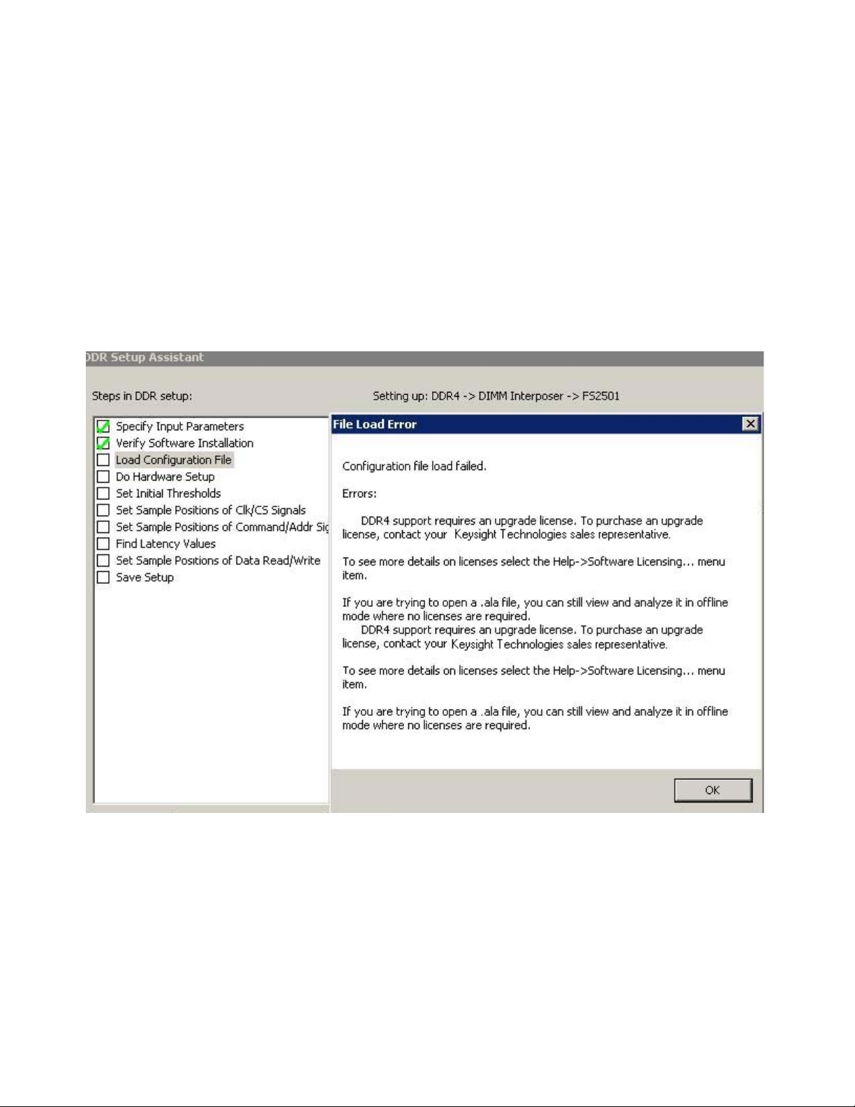
• If you selected DDR4 or LPDDR3 as the DDR Bus Type in Step 1 of the wizard and you do not
have the B4621B (for DDR) and B4623B (for LPDDR) software licenses installed, then you will
not be able to load a standard or a custom DDR4/LPDDR3 configuration file in this step. In
such a situation, the following error message will be displayed. To get DDR4 and LPDDR3
support, you must purchase the B4621B and B4623B license respectively.
3 If necessary, navigate to the configuration file.
The default location for standard configuration files is:
C:\Documents and Settings\All Users\Documents\Keysight Technologies\Logic Analyzer\
Default Configs\Keysight\
Then, select the file and click Open.
4Click Step Completed -->.
Configuration files typically include:
• A general purpose probe tool to define the mapping between device under test signals and logic
analyzer pods. If the configuration file doesn't include one, you can add it yourself. See "To define
probes" (in the online help).
DDR Setup Assistant User Guide 41
Page 42

3 Using the DDR Setup Assistant
• A DDR Bus Decoder tool for decoding the captured data. If the configuration file doesn't include
one, you can add it yourself. See "To add new tools" (in the online help).
For more information about the configuration files provided for the different DDR probing options,
see “Options for Probing DDR Devices" on page 13.
Next • “Step - Do Hardware Setup" on page 43
42 DDR Setup Assistant User Guide
Page 43
Step - Do Hardware Setup
The DDR Setup Assistant takes no actions in this step; it just waits until you tell it the step is
completed.
In this step, you must make the proper connections between the device under test and the logic
analyzer. This includes:
• Connecting the probing solution to the device under test. (For more information, see Chapter 1,
“Options for Probing DDR Devices,” starting on page 13.)
• Connecting the probing solution to the logic analyzer.
When connecting the probing solution to the logic analyzer, the configuration's probe set maps out
the probing solution to logic analyzer connection. To access the probe set's mapping:
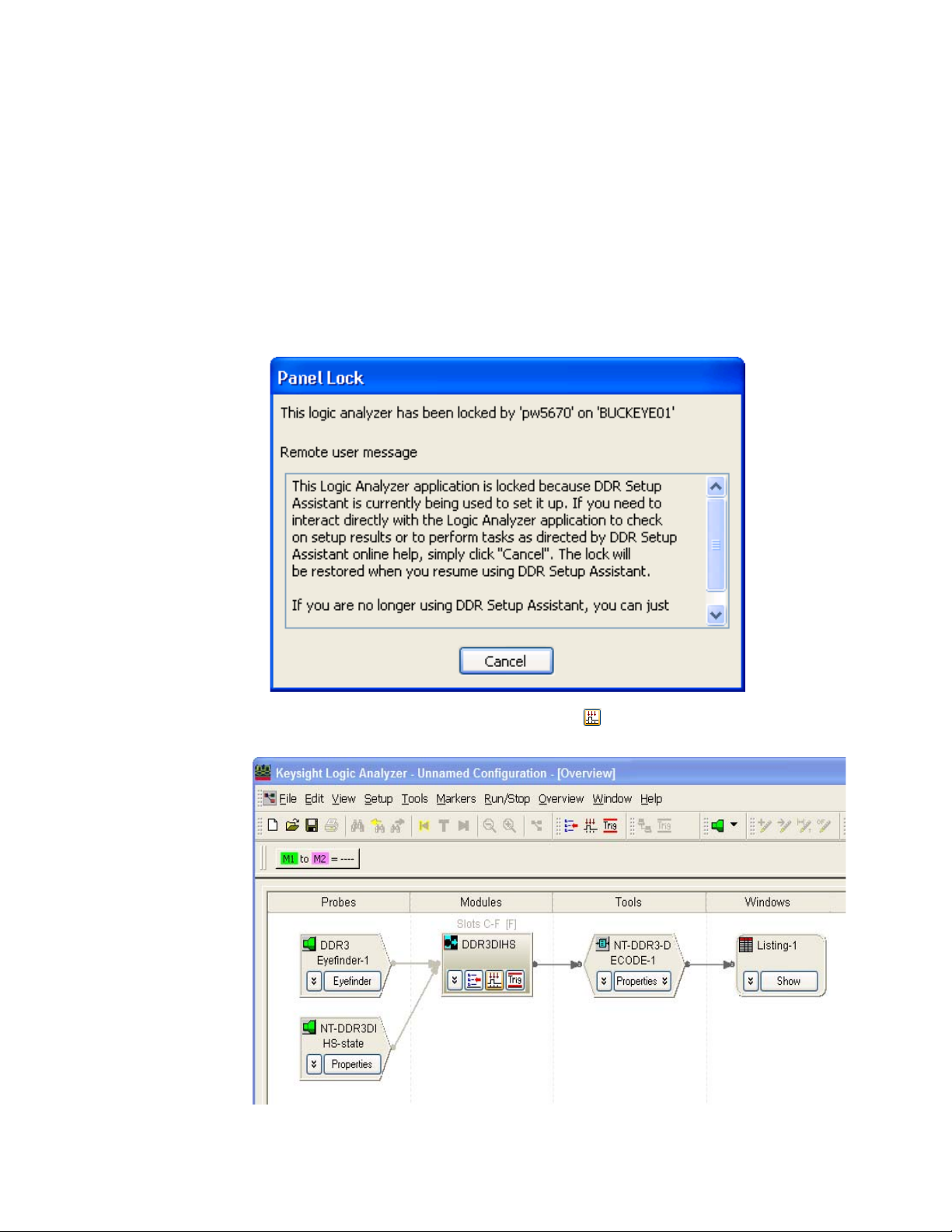
1 Go to the Keysight Logic Analyzer application.
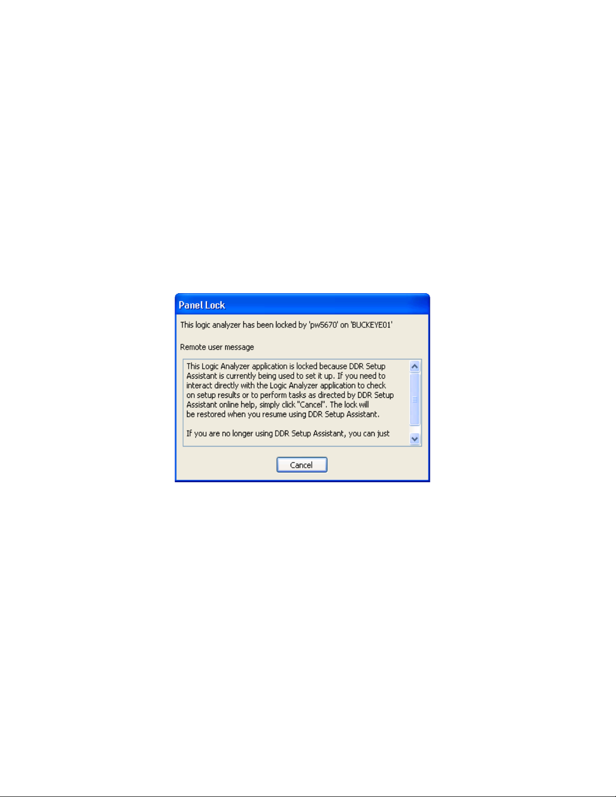
2 You may have to click Cancel in the Panel Lock dialog.
Using the DDR Setup Assistant 3
3In the Keysight Logic Analyzer application, click the Overview tab (or the System Overview icon) to
view the Overview window.
In the Overview window, you see a picture of the Probes, Modules, Tools, and Windows used in
the configuration.
4 Click the probe's Properties button.
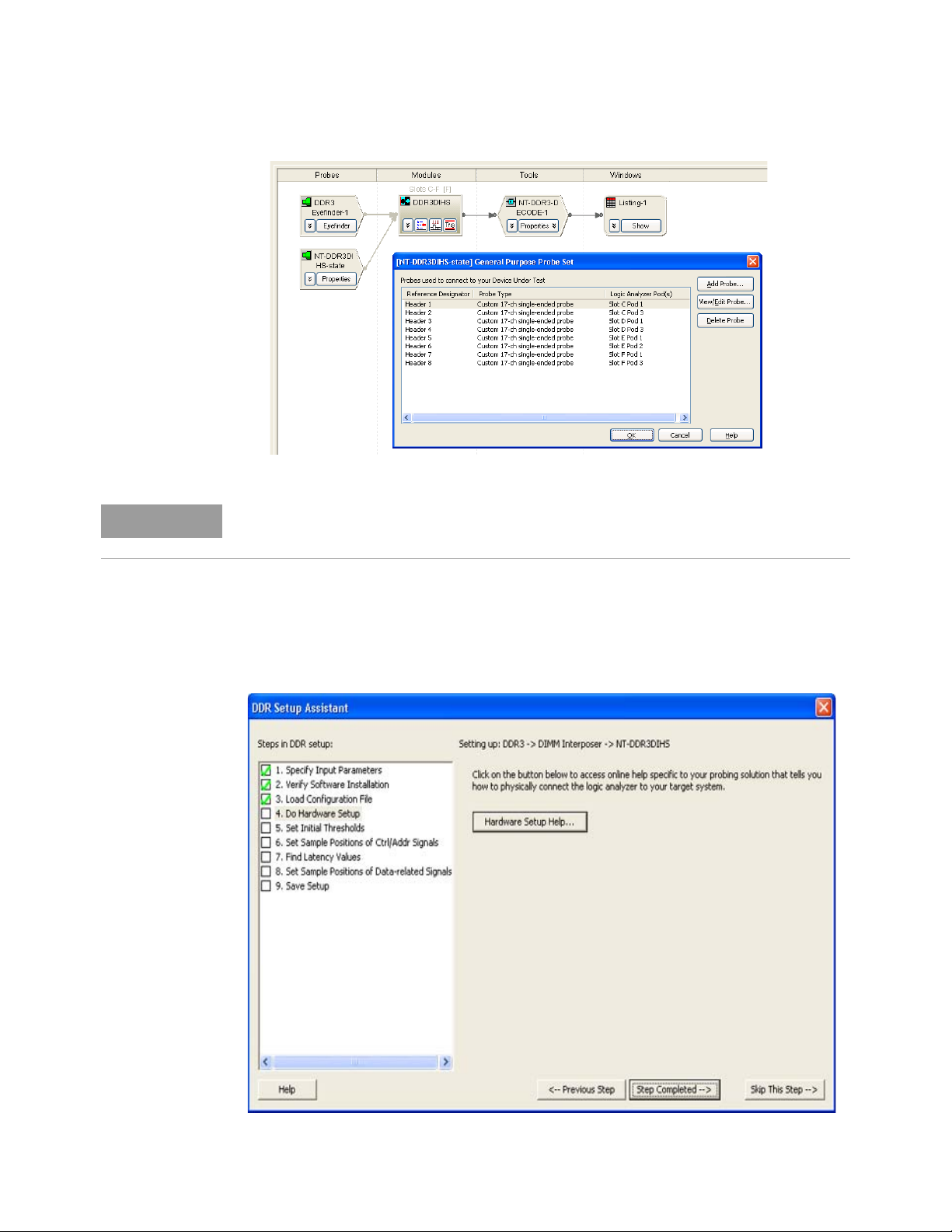
The General Purpose Probe Set dialog shows how the probe's reference designators map to the
logic analyzer pod cables. For example:
DDR Setup Assistant User Guide 43
Page 44
3 Using the DDR Setup Assistant
NOTE
The General Purpose Probe Set mapping is different for each configuration. Yours will like be
different than the one shown in the previous screen.
5 Carefully connect the probes to the logic analyzer pod cables using the mapping shown in the
General Purpose Probe Set dialog.
After you have made the proper probing solution to device under test and probing solution to logic
analyzer connections, click Step Completed -->.
44 DDR Setup Assistant User Guide
Page 45

Next • “Step - Set Initial Thresholds" on page 46
Using the DDR Setup Assistant 3
DDR Setup Assistant User Guide 45
Page 46
3 Using the DDR Setup Assistant
Step - Set Initial Thresholds
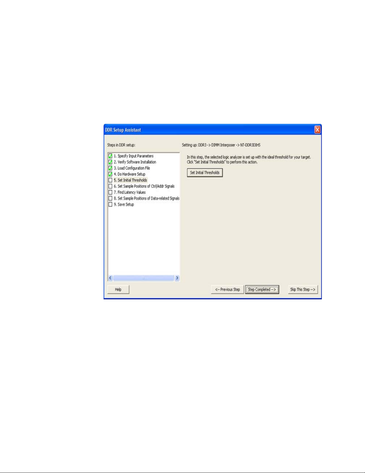
In the Set Initial Thresholds step, the DDR Setup Assistant automatically sets the initial threshold
voltages and detects if there are any problems with the settings.
1 Set up your device under test to have read and write traffic (see “Setting Up Read and Write
Traffic in the DUT" on page 33).
2Click Set Initial Thresholds.
The DDR Setup Assistant analyzes the swing of certain control signals to determine the best
threshold voltage settings.
3 If there are problems with the automated initial threshold voltage settings, use the default
threshold specified by the configuration file.
4Click Step Completed -->.
Next • “Step - Set Sample Positions of Ctrl/Addr Signals (not applicable to U4154A/B Logic
Analyzer)" on page 51
46 DDR Setup Assistant User Guide
Page 47
Using the DDR Setup Assistant 3
NOTE
Step - Set Sample Positions of Clk/CS Signals (only applicable to U4154A/B Logic Analyzer)
In this step, you set the sample positions of clock and chip select signals when using the U4154A/B
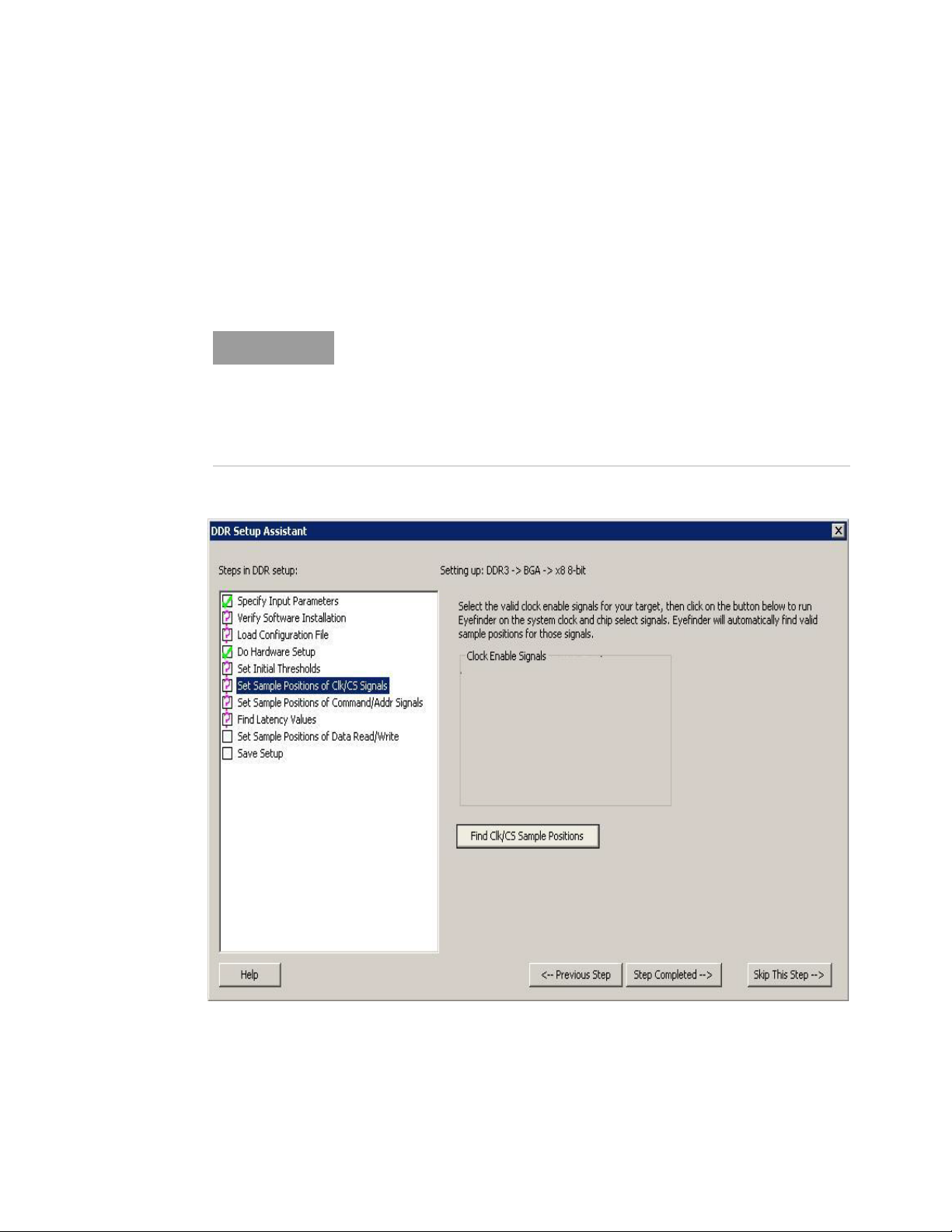
Logic Analyzer module. For this step, DDR Setup Assistant runs the eyescan feature of the U4154A/B
Logic Analyzer module to automatically calculate and set the optimal sample positions for the clock
and chip select signals.
This step is only applicable to the U4154A/B Logic Analyzer.
If you selected DDR4 as the bus type in step 1 - Specify Input Parameters, then
an additional field DDR4 Command Latency is displayed in this step.
DDR4 Command latency is defined as the number of clocks from chip select
going low until the command and address busses are valid.
Select valid clock enable signals and specify a value (ranging from 0 to 6) for
DDR4 Command Latency.
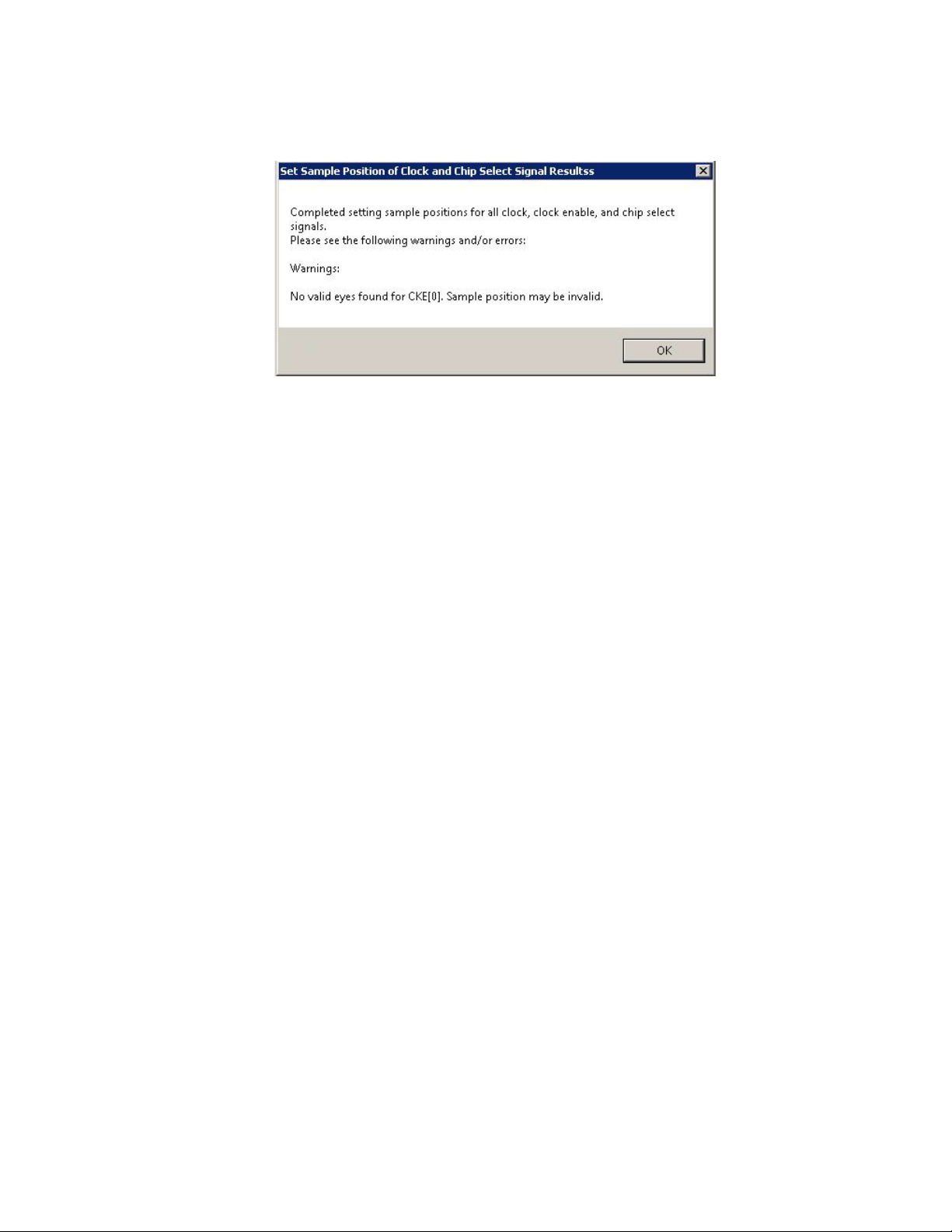
1 Click Find Clk/CS Sample Positions.
2 If the eyescan run completes but gives you warnings, you should check the warnings and re-run if
necessary.
DDR Setup Assistant User Guide 47
Page 48
3 Using the DDR Setup Assistant
3 When the clock and chip select signal sample positions have been properly set, click Step
Completed -->.
Next • “Step - Set Sample Positions of Command/Addr Signals (only applicable to U4154A/B Logic
Analyzer)" on page 49
48 DDR Setup Assistant User Guide
Page 49
Using the DDR Setup Assistant 3
Step - Set Sample Positions of Command/Addr Signals (only applicable to U4154A/B Logic Analyzer)
In this step, you set the sample positions of command and address signals when using the U4154A/B
Logic Analyzer module. For this step, DDR Setup Assistant runs the eyescan feature of the U4154A/B
Logic Analyzer module to automatically calculate and set the optimal sample positions for the
command and address signals.
This step is only applicable to the U4154A/B Logic Analyzer.
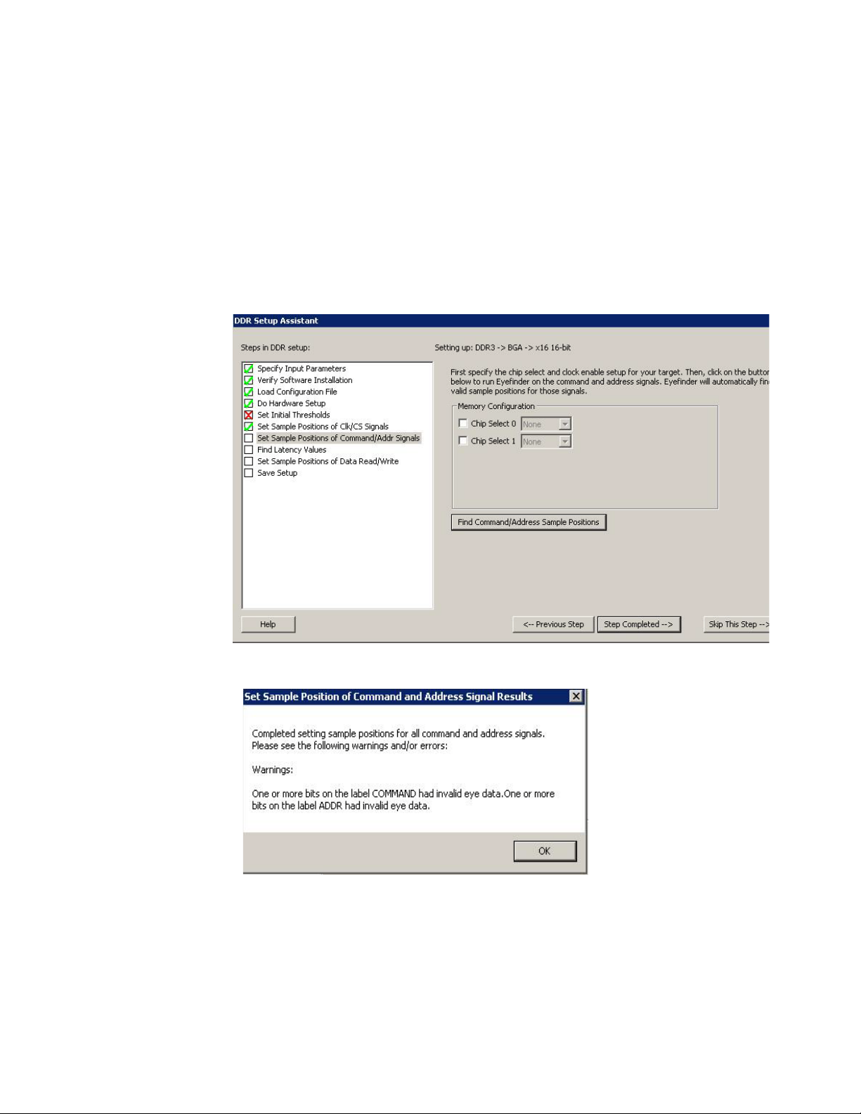
1 Click Find Command/Address Sample Positions.
2 If the eyescan run completes but gives you warnings, you should check the warnings and re-run if
necessary.
You should determine the cause of these messages by looking at the Keysight Logic Analyzer
application's Thresholds and Sample Positions dialog and perhaps re-running the set up. See
“Setting Up Thresholds and Sample Positions on DDR Address/Control Signals" on page 71.
3 When the command and address signal sample positions have been properly set, click Step
Completed -->.
Next • “Step - Find Latency Values" on page 53
DDR Setup Assistant User Guide 49
Page 50

3 Using the DDR Setup Assistant
50 DDR Setup Assistant User Guide
Page 51
Using the DDR Setup Assistant 3
Step - Set Sample Positions of Ctrl/Addr Signals (not applicable to U4154A/B Logic Analyzer)
In this step, the DDR Setup Assistant runs the logic analyzer Thresholds and Sample Positions set up
(also known as normal logic analyzer eye finder) to set the sample positions of the Control and
Address signals.
This step is not applicable to the U4154A/B Logic Analyzer.
1 Again, make sure your device under test has read and write traffic (see “Setting Up Read and
Write Traffic in the DUT" on page 33).
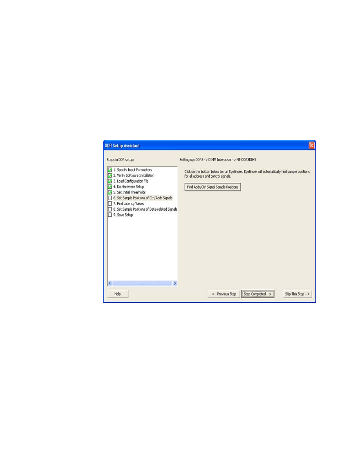
2Click Find Addr/Ctrl Signal Sample Positions.
3 If the Thresholds and Sample Positions set up cannot run for some reason, click Addr/Ctrl Signal
Sample Position Help... (which directs you to “If there are problems with finding Ctrl/Addr sample
positions" on page 52).
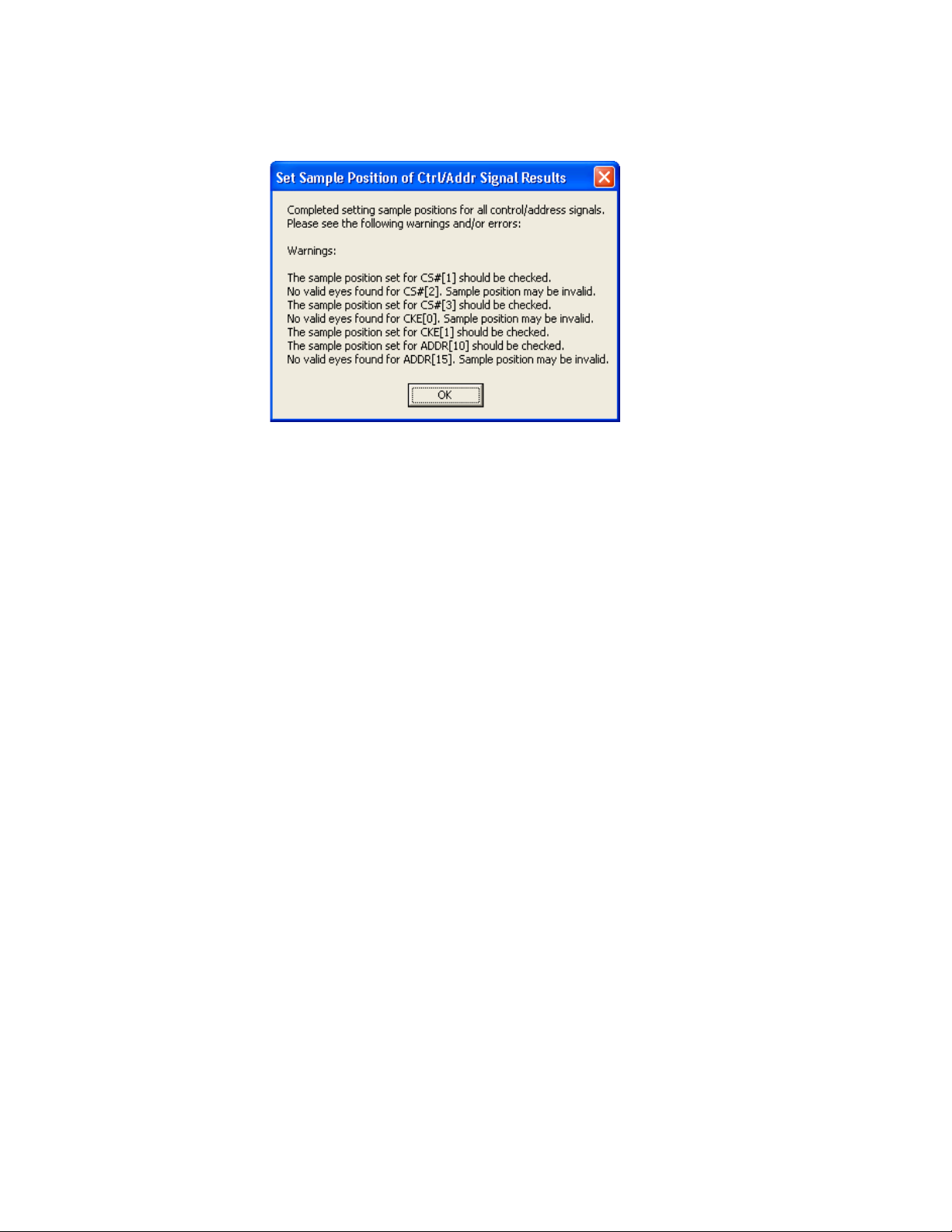
4 If the Thresholds and Sample Positions set up run completes but gives you warnings, you should
check the warnings and re-run if necessary.
DDR Setup Assistant User Guide 51
Page 52
3 Using the DDR Setup Assistant
For example, in the previous dialog, it may be that the CS#1-3, CKE0-1, ADDR15 signals are not
being used, and these messages can safely be ignored. However, ADDR10 is generally used, so
you should determine the cause of these messages by looking at the Keysight Logic Analyzer
application's Thresholds and Sample Positions dialog and perhaps re-running the set up. See
Chapter 4, “Setting Up Thresholds and Sample Positions on DDR Address/Control Signals,”
starting on page 71.
5 When the Addr/Ctrl signal sample positions have been properly set, click Step Completed -->.
Next • “Step - Find Latency Values" on page 53
If there are problems with finding Ctrl/Addr sample positions
Generally, problems finding the Ctrl/Addr signal sample positions are basic. Check these things:
• Make sure the device under test is powered on and that the probing solution connections to the
device under test and to the logic analyzer are good.
• Make sure there is memory traffic on the DDR bus. Dense traffic is better than sparse traffic when
running the logic analyzer Thresholds and Sample Positions set up to determine the Ctrl/Addr
signal sample positions.
See Also • “Solving Problems with Thresholds and Sample Positions Set Up" on page 76
52 DDR Setup Assistant User Guide
Page 53
Step - Find Latency Values
NOTE
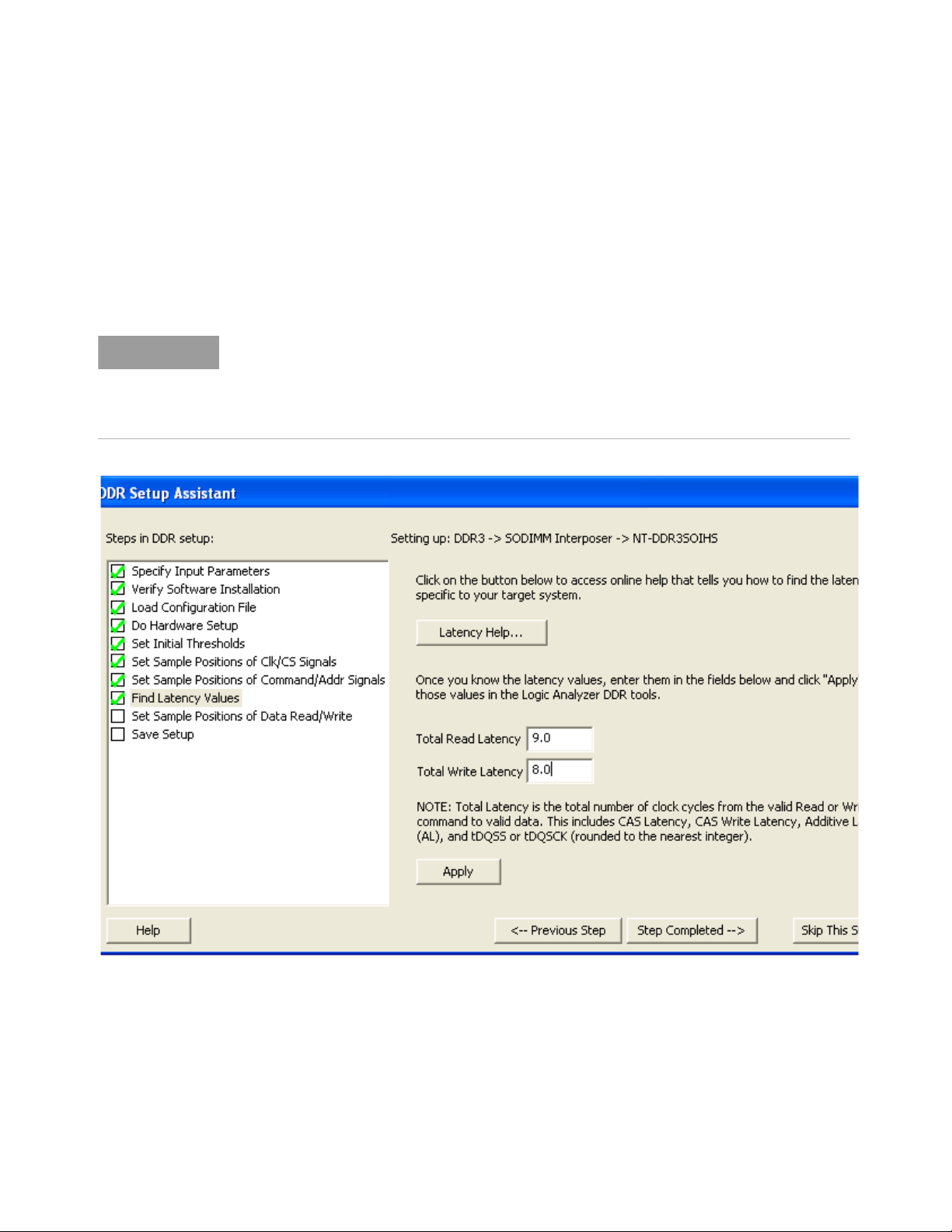
In this step, if you don't already know the latency values of the device under test, you set up the
Mode Register Settings (MRS) trigger, take a trace, and scan it for latency values. See:
• “Taking a Mode Register Settings (MRS) Trace" on page 54
When you have the proper latency values for the device under test, enter the values into the DDR
Setup Assistant; then, click Apply.
The latency values that you specify in this step represent the total latency for your system and
therefore should include parameters that affect total latency. For instance, if your system has
Additive Latency (AL), then you must include it in the Total Latency values. Similarly, if tDQSS
or tDQSCK parameters are greater than one full clock cycle, then you must add these values
(rounded to the nearest integer) in the Total Latency values.
Using the DDR Setup Assistant 3
When you apply the latency values settings, the DDR Setup Assistant automatically transfers these
settings to the DDR Bus Decoder and in the DDR3 Eyefinder / Eyescan.
You can also modify the DDR Bus Decoder and DDR3 Eyefinder / Eyescan settings yourself (or edit
them later) by following these instructions:
• “Setting Latency Values in DDR Bus Decoder" on page 57
• “Setting Latency Values in DDR3 Eyefinder" on page 59
• “Setting Latency Values in Eyescan" on page 60
DDR Setup Assistant User Guide 53
Page 54
3 Using the DDR Setup Assistant
When you have found and transferred the latency values, click Step Completed -->.
Next • “Step - Set Sample Positions of Data-related Signals (not applicable to U4154A/B logic
analyzer)" on page 64
• “Step - Set Sample Positions of Data Read/Write (only applicable to U4154A/B Logic
Analyzer)" on page 65
Taking a Mode Register Settings (MRS) Trace
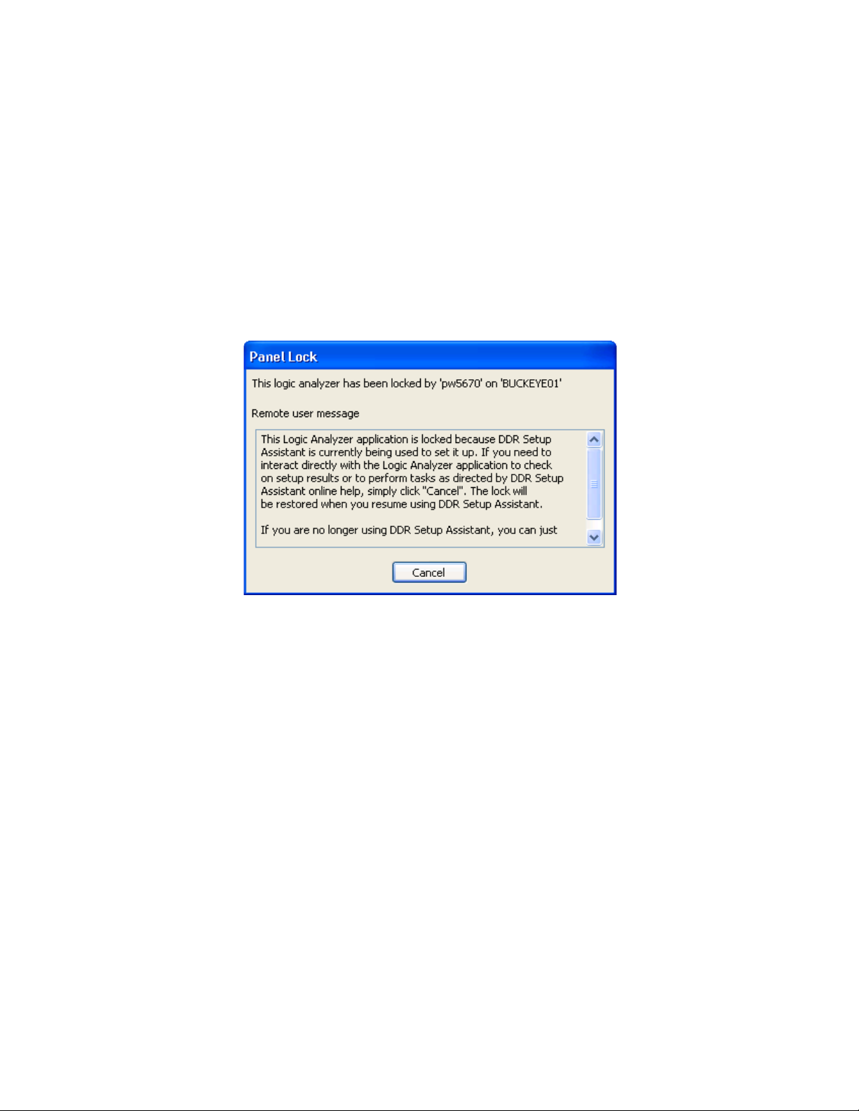
1 Go to the Keysight Logic and Protocol Analyzer application.
2 You may have to click Cancel in the Panel Lock dialog.
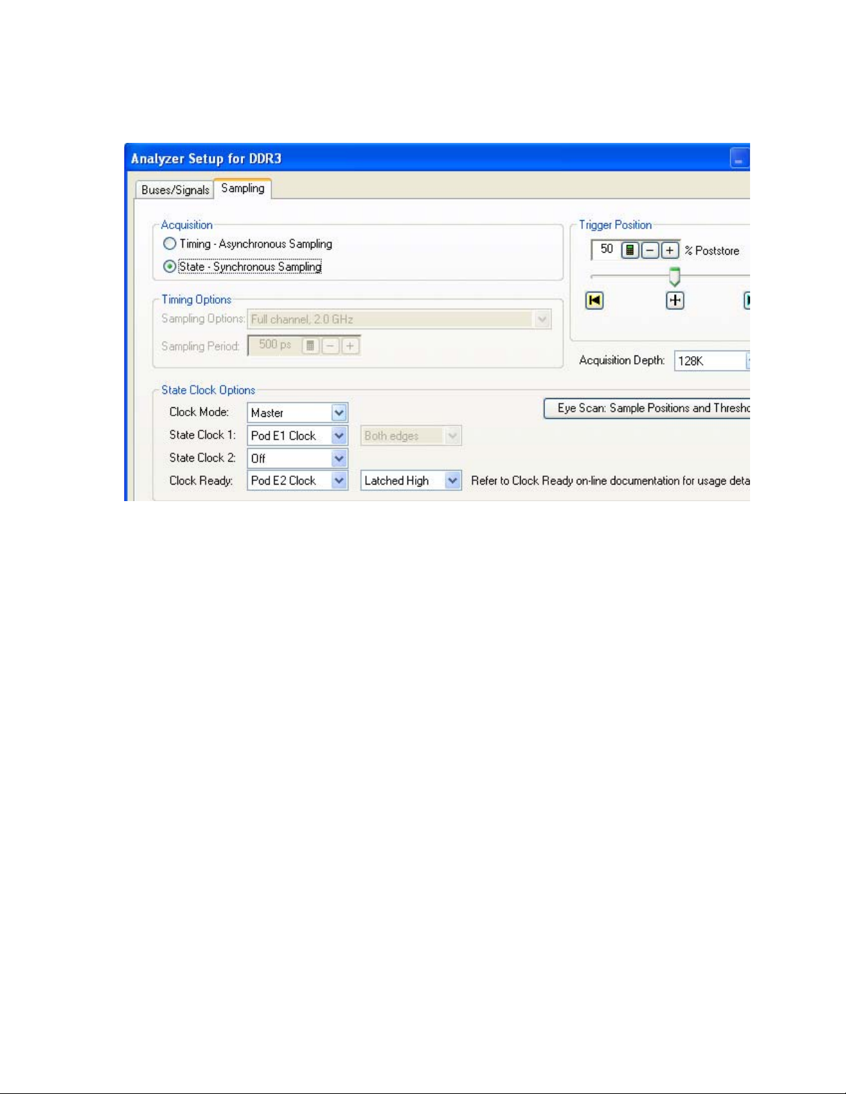
3 For 16962A or 16960A Logic Analyzers - In the Keysight and Protocol Logic Analyzer
application's Sampling Setup, change the Clock Ready state clock option to Latched High for the
clock input of Pod 2 (Clk2) as displayed in the following screen.
54 DDR Setup Assistant User Guide
Page 55
Using the DDR Setup Assistant 3
The CKE0 signal is routed to the CLK input on pod 2 of the logic analyzer module and CK0 is
routed to the CLK input on pod 1.
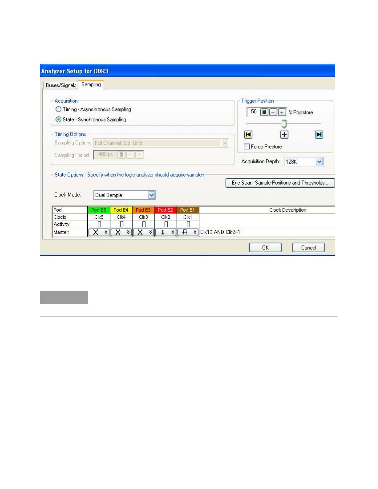
For U4154A/B Logic Analyzers - In the Keysight Logic and Protocol Analyzer application's
Sampling Setup, set the clock input of Pod 2 (Clk2) as the state clock qualifier - Qualifier -High as
displayed in the following screen. Notice that the Qualifier - High option is represented by "1" in
the following screen.
DDR Setup Assistant User Guide 55
Page 56
3 Using the DDR Setup Assistant
NOTE
4 Power off the device under test.
5In the Keysight Logic Analyzer application's Advanced Trigger dialog, recall the Mode Register
Settings trigger.
If your device under test does not complete Mode Register Setting before the first memory write,
change the Mode Register Settings trigger by replacing the sequence step that triggers on the first
memory write with the "Run until user stop" trigger function. (Do not change the default storage.)
6 Run the logic analyzer with Mode Register Settings trigger (clock ready latched high on
CKE0_qual)
The logic analyzer runs status shows "Waiting for trigger in Trigger Step 1...".
7 Power on the device under test.
8In the Keysight Logic Analyzer application's Listing window, go to the trigger.
The trigger is the first Write to Memory.
9 Scroll backward from the trigger to find the last Latency settings before the memory write.
56 DDR Setup Assistant User Guide
Page 57
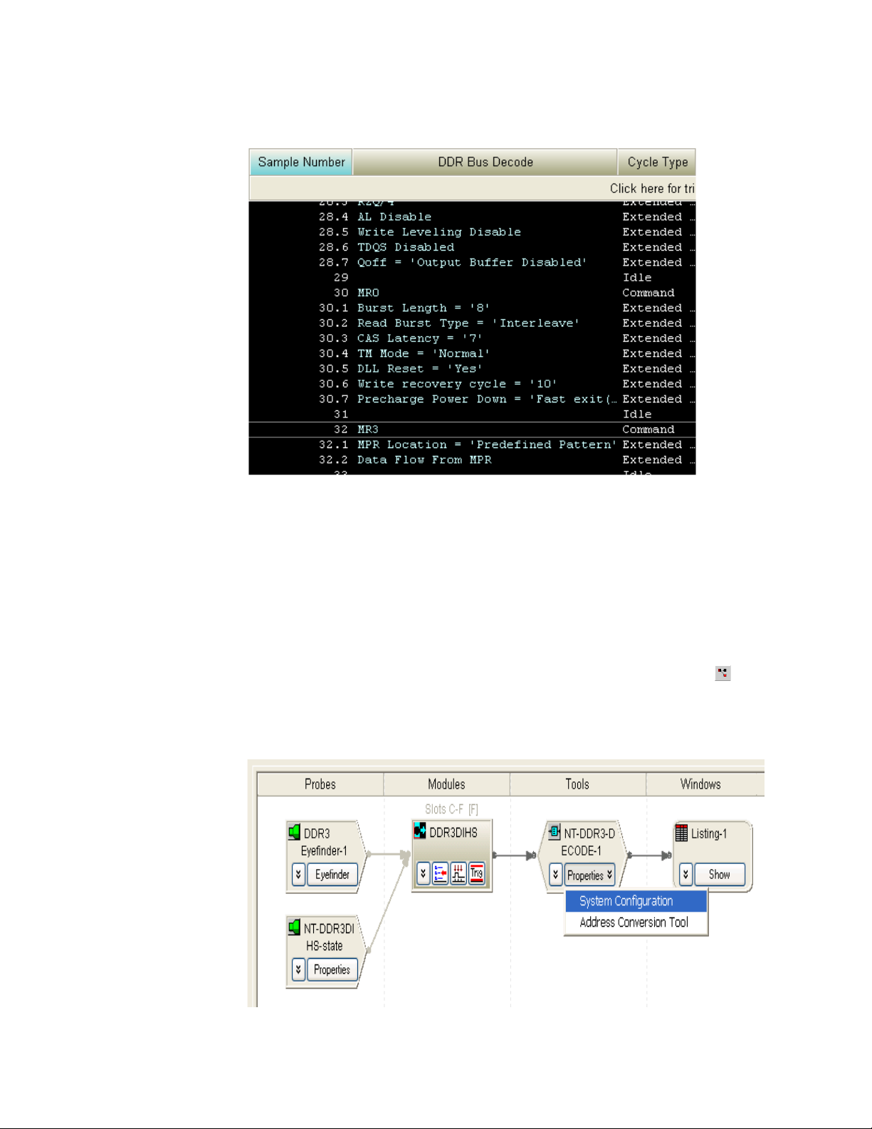
Using the DDR Setup Assistant 3
10 Record the values for:
• Read latency.
• Write latency.
• Burst length.
• Burst type (sequential or interleaved).
Setting Latency Values in DDR Bus Decoder
To set the device under test's latency and burst values in the DDR Bus Decoder:
1In the Keysight Logic and Protocol Analyzer application, click the Overview tab (or the System
Overview icon) to view the Overview window.
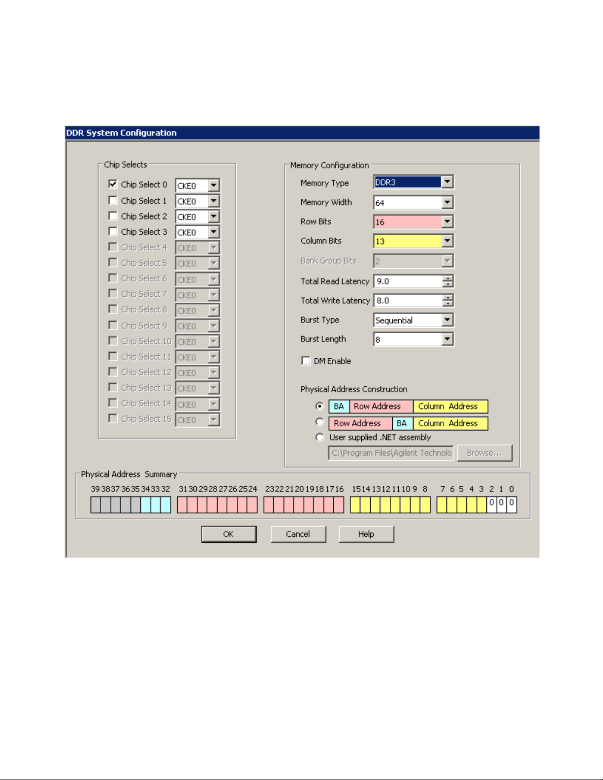
2 In the DDR Bus Decoder tool (in the Tools column), click the Properties button and choose System
Configuration.
DDR Setup Assistant User Guide 57
Page 58
3 Using the DDR Setup Assistant
The System Configuration dialog is displayed.
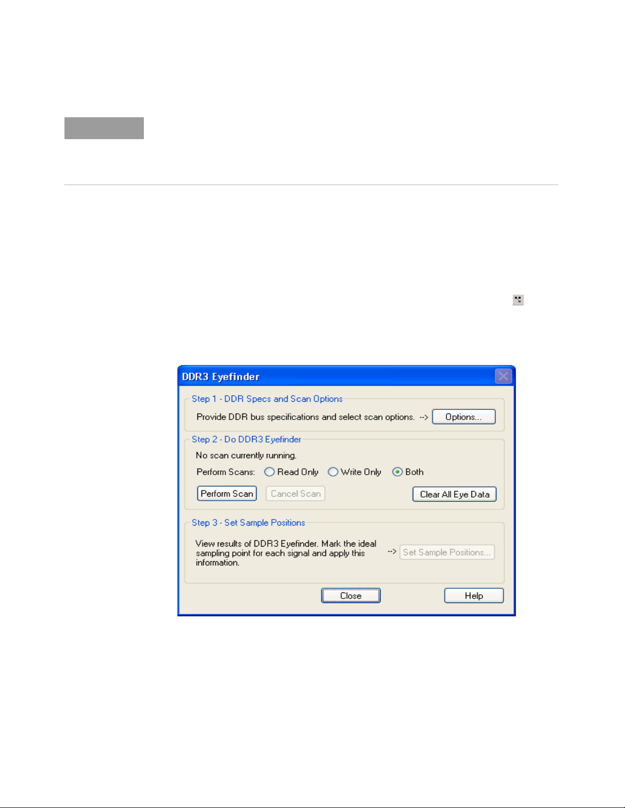
3 In the System Configuration dialog, enter or select:
• The appropriate Chip Select and CKE for the device under test.
• Total Read Latency(or Read Offsetin some decoders) — Enter the total Read latency value
recorded earlier.
• Total Write Latency(or Write Offsetin some decoders) — Enter the total Write latency value
recorded earlier.
58 DDR Setup Assistant User Guide
Page 59
NOTE
The latency values that you specify in the System Configuration dialog represent the total
latency for your system and therefore should include parameters that affect total latency. For
instance, if your system has Additive Latency (AL), then you must include it in the Total Latency
values. Similarly, if tDQSS or tDQSCK parameters are greater than one full clock cycle, then
you must add these values (rounded to the nearest integer) in the Total Latency values.
• Burst Type— Enter the Burst type value recorded earlier.
• Burst Length— Enter the Burst length value recorded earlier.
4Click OK.
Setting Latency Values in DDR3 Eyefinder
To set the device under test's latency and burst values in DDR3 Eyefinder:
1In the Keysight Logic and Protocol Analyzer application, click the Overview tab (or the System
Overview icon) to view the Overview window.
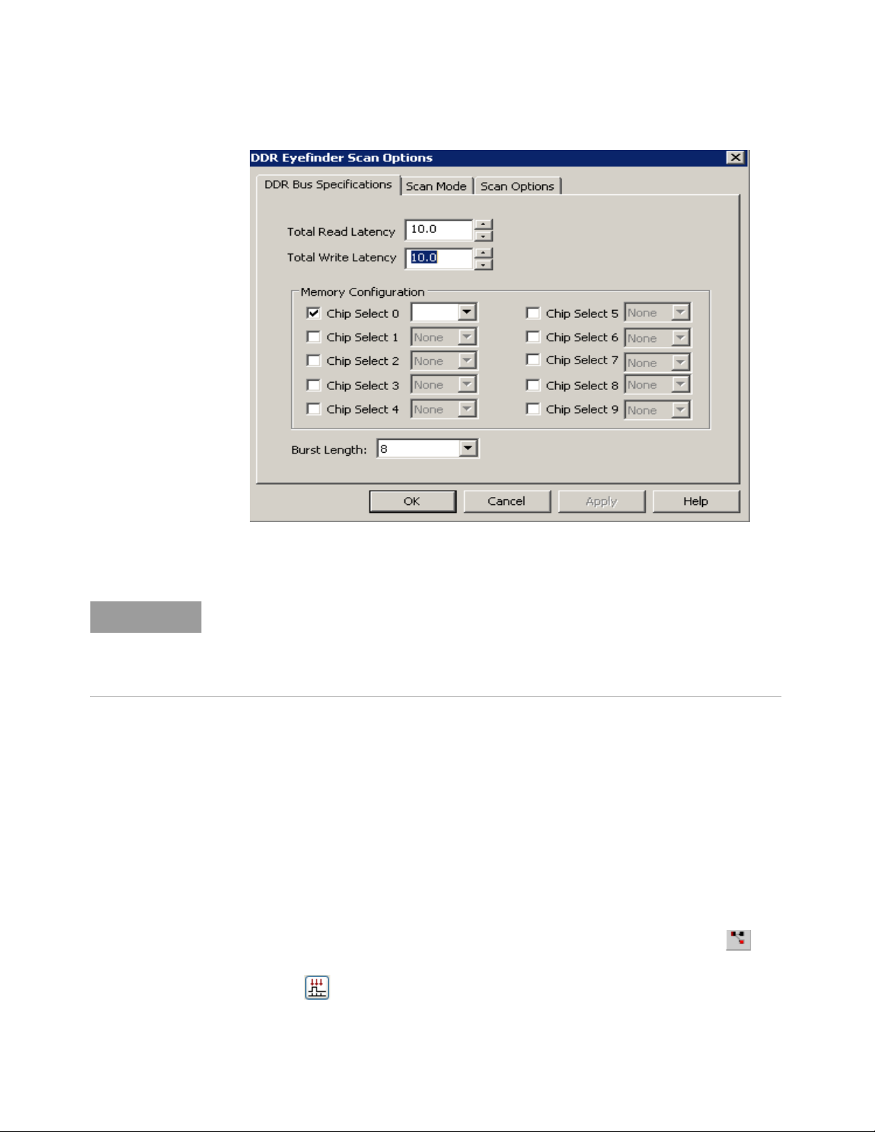
2 In the DDR3 Eyefinder probe (in the column on the left), click the Eyefinder button.
3 In the DDR3 Eyefinder dialog, click Options....
Using the DDR Setup Assistant 3
4 In the DDR3 Eyefinder Scan Options dialog's DDR Bus Specifications tab, enter or select:
DDR Setup Assistant User Guide 59
Page 60
3 Using the DDR Setup Assistant
NOTE
• Total Read Latency— Enter the total read latency value recorded earlier.
• Total Write Latency— Enter the total Write latency value recorded earlier.
The latency values that you specify in the DDR3 Eyefinder represent the total latency for your
system and therefore should include parameters that affect total latency. For instance, if your
system has Additive Latency (AL), then you must include it in the Total Latency values.
Similarly, if tDQSS or tDQSCK parameters are greater than one full clock cycle, then you must
add these values (rounded to the nearest integer) in the Total Latency values.
• Memory Configuration— Choose the appropriate Chip Select(s) for the memory path being
traced.
• Burst Length— Enter the Burst length value recorded earlier.
5Click OK.
Setting Latency Values in Eyescan
When using the U4154A/B Logic Analyzer module, you can modify the device under test's latency
and burst values in Eyescan. The Eyescan feature of U4154A/B displays the default latency values or
the latency values that you initially set using the DDR Setup Assistant tool. If required, you can
modify these values for subsequent eyescan runs.
To modify the latency and burst values using the Eyescan feature:
1 In the Keysight Logic and Protocol Analyzer application, click the Overview tab (or the
System Overview icon) to view the Overview window.
2 Click the Sampling Setup icon in the U4154A/B logical module displayed under the
Modules column in the Overview window.
The Sampling tab of the Analyzer Setup dialog box is displayed.
60 DDR Setup Assistant User Guide
Page 61
Using the DDR Setup Assistant 3
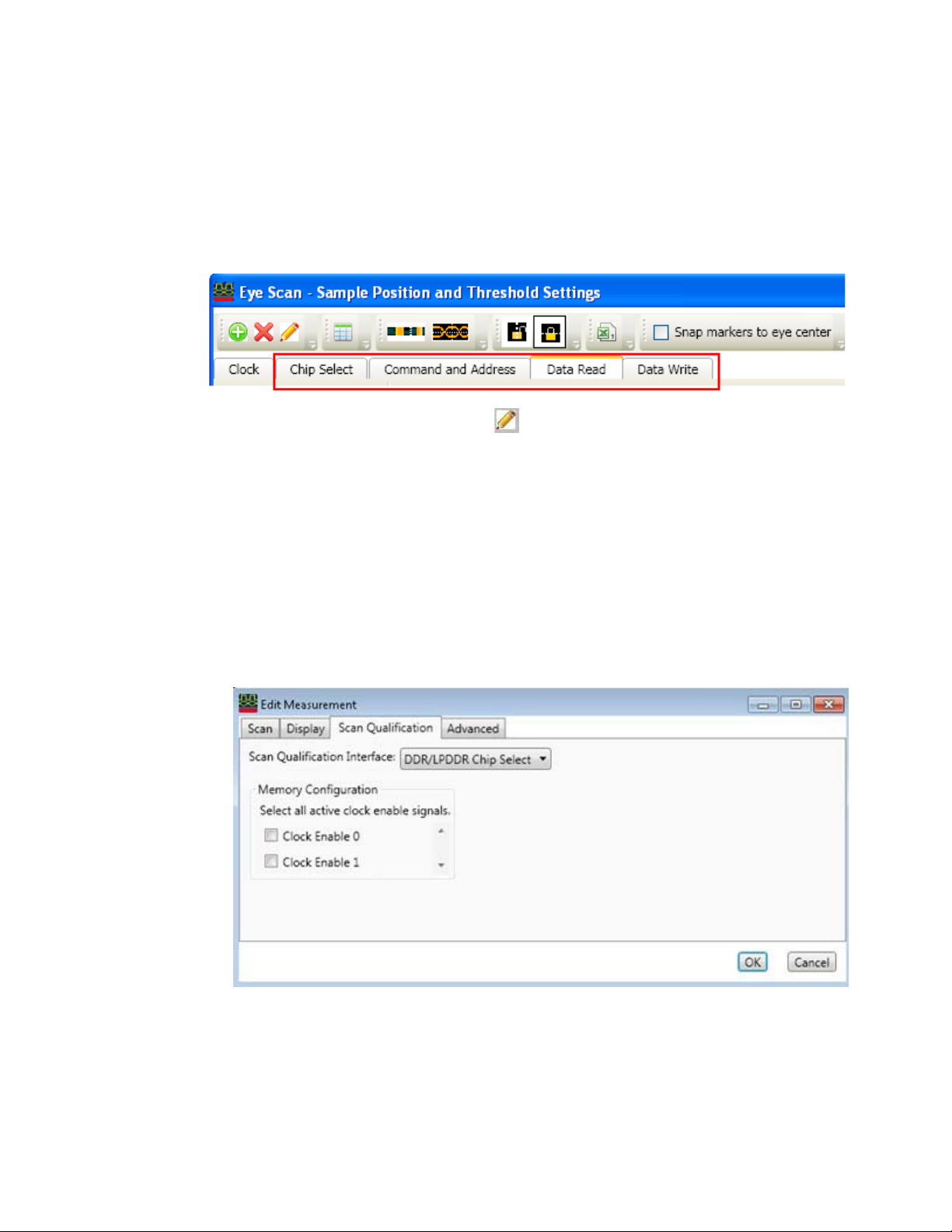
3 Click the Eye Scan: Sample Positions and Thresholds... button.
The Eye Scan - Sample Position and Threshold Settings dialog box is displayed.
4 In the Eye Scan - Sample Position and Threshold Settings dialog box, select the tab for Chip
Select, Command and Address, Data Read or Data Write to modify the scan qualification for the
appropriate signals.
5 Click the Edit Current Measurement toolbar button.
The Edit Measurement dialog box is displayed.
6 Click the Scan Qualification tab in this dialog box.
7 Based on the signals tab you selected in step 4, the options are displayed in the Scan
qualification interface listbox. Select one of the following options from this listbox:
• DDR/LPDDR Chip Select option - to modify the scan qualification for chip select signals.
• DDR/LPDDR Command and Address option - to modify the scan qualification for command
and address signals.
• DDR Data Read option - to modify the scan qualification for data read signals.
• DDR Data Write option - to modify the scan qualification for data write signals.
On selecting the DDR/LPDDR Chip Select option in the previous step, the following fields are
displayed for chip select scan qualification:
8 For the DDR/LPDDR Chip Select signals, make the appropriate selections based on the active
clock enable signals.
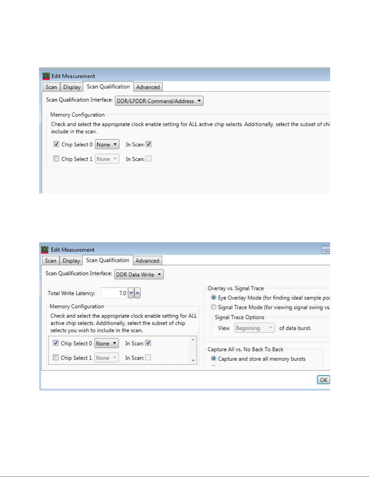
On selecting the DDR/LPDDR Command and Address option in the step 7, the following fields are
displayed for scan qualification:
DDR Setup Assistant User Guide 61
Page 62
3 Using the DDR Setup Assistant
9 For the DDR/LPDDR Command and Address signals, make the appropriate Memory
Configuration selections based on the chip selects used in the DUT.
On selecting the DDR/LPDDR Data Read or Data Write interface in step 7, the following fields are
displayed for scan qualification:
10 For DDR Data Read or Write signals:
g The DUT's Total Read/Write Latency value that you set up in the initial DDR setup is displayed.
If needed, modify this value. To find an appropriate value of Total Read/Write Latency, you can
set up the Mode Register Settings (MRS) trigger, take a trace, and scan it for latency values.
62 DDR Setup Assistant User Guide
Page 63

Using the DDR Setup Assistant 3
NOTE
The latency values specified here represent the total latency for your system and therefore
should include parameters that affect total latency. For instance, if your system has Additive
Latency (AL), then you must include it in the Total Latency values. Similarly, if tDQSS or
tDQSCK parameters are greater than one full clock cycle, then you must add these values
(rounded to the nearest integer) in the Total Latency values.
h In the Memory Configuration section, choose the appropriate Chip Select(s) for the memory
path being traced.
i In the Burst Length field, specify the number of words read or written for each read/write
command. To find appropriate value of Burst Length for the DUT, you can set up the Mode
Register Settings (MRS) trigger, take a trace, and scan it for burst length.
11 Click OK to confirm the settings.
You can save the modified latency and burst values in the Logic Analyzer .ala or .xml
configuration file.
DDR Setup Assistant User Guide 63
Page 64
3 Using the DDR Setup Assistant
Step - Set Sample Positions of Data-related Signals (not applicable to U4154A/B logic analyzer)
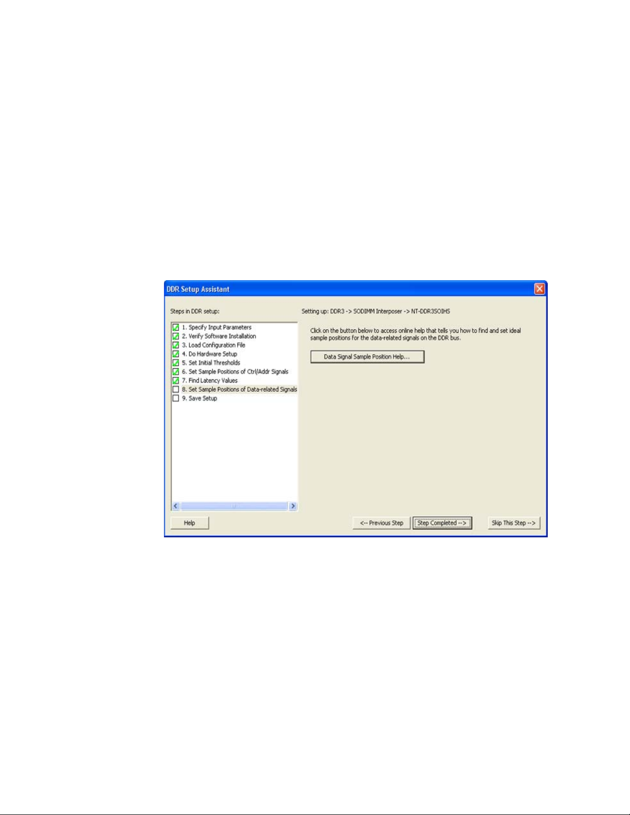
In this step, you set the sample positions of Data signals.
• With the 16960A or 16962A logic analyzers, use DDR3 Eyefinder to set the sample positions of
data signals. See “Your First DDR3 Eyefinder Scan (16962A logic analyzers only)" on page 80.
• With the 16950A/B or 16951B logic analyzers, use the logic analyzer's timing zoom feature to set
the sample positions of data signals. See Appendix A, “Setting Data Sample Positions with the
1695x Logic Analyzers,” starting on page 119.
This step is not applicable to U4154A/B Logic Analyzer module. For setting the sample positions of
Data signals when using the U4154A/B module, refer to the topic “Step - Set Sample Positions of
Data Read/Write (only applicable to U4154A/B Logic Analyzer)" on page 65.
After setting the sample positions of Data signals, click Step Completed -->.
Next • “Step - Save Setup" on page 68
64 DDR Setup Assistant User Guide
Page 65
Using the DDR Setup Assistant 3
NOTE
Step - Set Sample Positions of Data Read/Write (only applicable to U4154A/B Logic Analyzer)
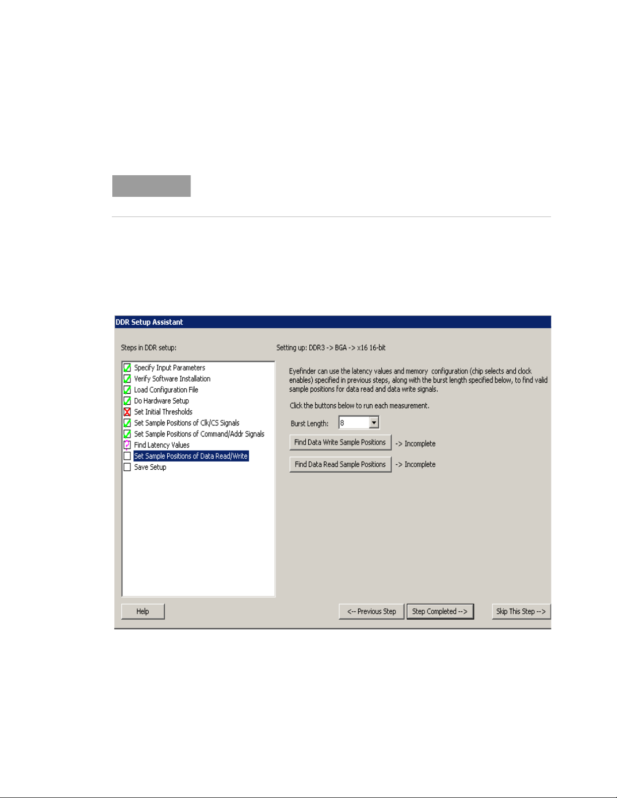
In this step, you set the sample positions of Data signals when using the U4154A/B Logic Analyzer
module.
The fields displayed in this step differ if you selected DDR4 bus type in step 1.
Therefore, the procedure for setting sample positions for DDR4 Data signals is
described separately in this topic.
For this step, DDR Setup Assistant runs the eyescan feature of the U4154A/B Logic Analyzer module
to automatically calculate and set the optimal sample positions for the data signals.
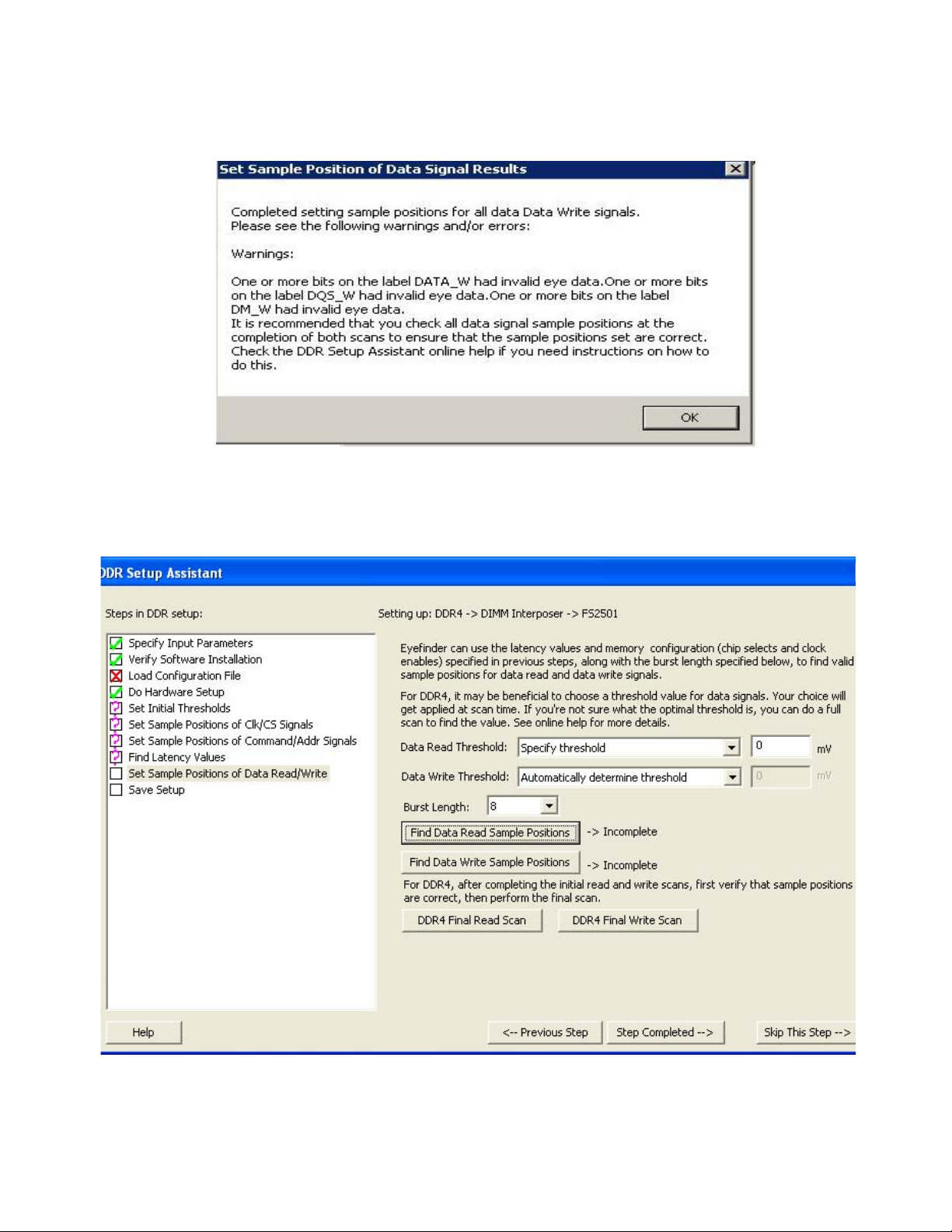
• Click Find Data Write Sample Positions to find the optimal and valid sample positions for the data
write signals.
• Click Find Data Read Sample Positions to find the optimal and valid sample positions for the data
read signals.
If the eyescan run completes but gives you warnings, you should check the warnings and re-run the
eyescan in this step.
DDR Setup Assistant User Guide 65
Page 66
3 Using the DDR Setup Assistant
After setting the sample positions of Data signals, click Step Completed -->.
To find and set sample positions for DDR4 Data related signals
66 DDR Setup Assistant User Guide
Page 67

Using the DDR Setup Assistant 3
1 Set the threshold for DDR4 data read and write signals. You can set the threshold in either of the
following two ways:
• From the Data Read Threshold and Data Write Threshold listboxes, select the Automatically
determine threshold option to let DDR Setup Assistant automatically determine the best
threshold setting. The middle of the signal swing is used in this case.
• From the Data Read Threshold and Data Write Threshold listboxes, select the Specify
threshold option to manually specify the threshold value. This is particularly useful in case of
DDR4 signals for which the automatically determined threshold value may not be an ideal
threshold to use.
If you selected to manually specify the threshold value for DDR4 data signals, you can
determine the best threshold setting by performing the following steps:
i Access the already open Logic and Protocol Analyzer application. To do this, you need to
cancel the "Panel Lock" dialog displayed by DDR Setup Assistant.
ii Open the Setup dialog box of the logic analyzer module.
iii Click the Sampling tab.
iv Click the Eye Scan: Sample Positions and Thresholds button
v Click the Data Read measurement tab.
vi Click Edit Current Measurement toolbar button and then select Do full time/voltage scan
in the Scan tab.
vii Click OK.
viii Run the eyescan measurement by clicking Run this measurement.
ix View the eyescan results to decide which threshold is likely to result in the best eye
openings. Note down the threshold value. If required, you can unlock the threshold
settings to move the threshold marker.
x Click the Data Write measurement tab.
xi Repeat steps vi-ix to view threshold for the Data Write measurement.
xii Once you have noted down the threshold that would result in best eye openings, click
Cancel to cancel the Eye scan - Sample Positions and Threshold Settings dialog.
xiii Click Cancel again to cancel the Analyzer Setup dialog.
xiv Access the already open DDR Setup Assistant and specify the obtained threshold values
in the Data Read Threshold and Data Write Threshold fields.
2 Select the Burst Length.
3 Click Find Data Read Sample Positions to find the optimal and valid sample positions for the data
read signals based on the specified threshold settings.
4 Click Find Data Write Sample Positions to find the optimal and valid sample positions for the data
write signals based on the specified threshold settings.
5 Once you have verified that the obtained sample positions for DDR4 data read and write signals
are correct, perform a final scan. You perform a final scan by clicking the DDR4 Final Read Scan
and DDR4 Final Write Scan buttons.
A final scan is a comparatively shorter scan than a main scan and is used to perform a final
setting to fine tune the obtained sample positions. A final scan verifies that the sample positions
are optimal not just for the first bit but for all 8 bits in the burst.
Based on the fine tuning needed, a final scan may result in only a minor change or no change at
all to the sample positions.
Next “Step - Save Setup" on page 68
DDR Setup Assistant User Guide 67
Page 68
3 Using the DDR Setup Assistant
Step - Save Setup
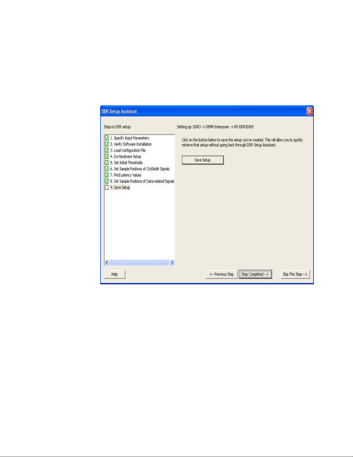
In this step, save your logic analyzer setup so that it can be opened later without having to perform
the DDR Setup Assistant steps again..
1Click Save Setup.
2 In the Save Setup dialog, browse to the location where you want to save the setup file, enter the
file name, and click Save.
3 In the message dialog that says the setup was saved successfully, click OK.
4Click OK.
After saving the configuration, click Step Completed -->.
Next • “Setup Complete" on page 69
68 DDR Setup Assistant User Guide
Page 69
Setup Complete
Using the DDR Setup Assistant 3
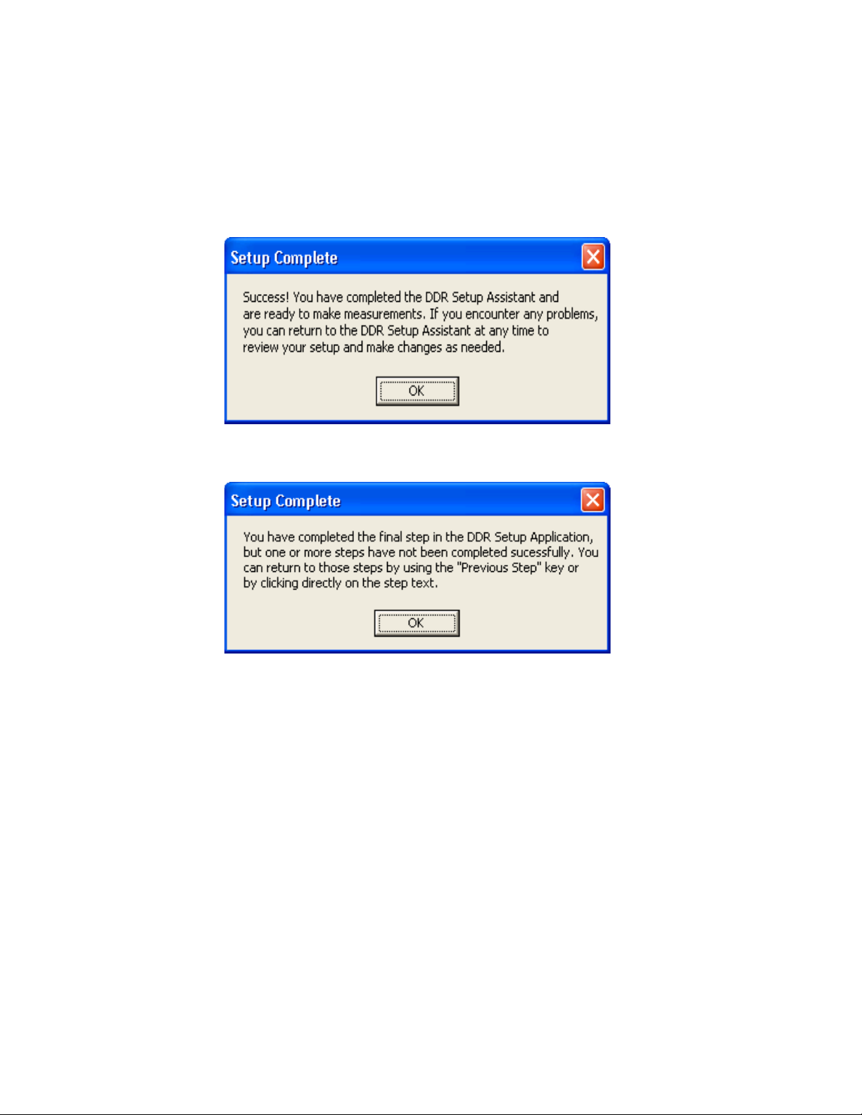
After clicking Step Completed --> in the last step of the DDR Setup Assistant, you get a Setup
Complete message.
The Setup Complete mesasge will tell you if any of the steps still need to be completed.
When the DDR setup is complete, you can use the DDR bus decoder and other tools to analyze
captured data.
See Also • “Setting Up Thresholds and Sample Positions on DDR Address/Control Signals" on page 71
• “Using DDR3 Eyefinder" on page 79
• “Validating the DDR Setup" on page 111
• “Capturing Data (Triggering)" on page 113
• “Decoding Captured Data" on page 117
DDR Setup Assistant User Guide 69
Page 70

3 Using the DDR Setup Assistant
70 DDR Setup Assistant User Guide
Page 71

DDR Setup Assistant
User’s Guide
4 Setting Up Thresholds and
Sample Positions on DDR Address/Control Signals
Setting Up Thresholds and Sample Positions / 72
Solving Problems with Thresholds and Sample Positions Set Up / 76
The Thresholds and Sample Positions dialog in the Keysight Logic Analyzer application's sampling
setup tab (also known as normal logic analyzer eye finder), is used to set the sampling positions of
the DDR address and control signals. This is necessary before DDR3 Eyefinder can be used to set the
data signal sample positions on 16960A or 16962A logic analyzers.
For U4154A/B logic analyzer, the DDR Setup Assistant sets the sampling positions on DDR
command, address, and data read and write signals using the U4154A/B eyescan feature. This
feature is also available in the Keysight Logic Analyzer application. You can also set the threshold
and sample positions on individual channels of U4154A/B using the Eye Scan - Sample positions
and Threshold Settings dialog box accessible by clicking the Eye scan: Sample Positions and
threshold button in the Sampling tab of the Setup dialog box.
The DDR Setup Assistant runs the Thresholds and Sample Positions set up for you; however, it may
run into some problems that require you to open and re-run the set up.
Page 72
4 Setting Up Thresholds and Sample Positions on DDR Address/Control Signals
Setting Up Thresholds and Sample Positions
The Thresholds and Sample Positions set up (also known as normal logic analyzer eye finder) is used
to set the sampling positions of the DDR address and control signals. This is necessary before DDR3
Eyefinder can be used to set the data signal sample positions (on 16962A and 16960A logic
analyzers).
1 Go to the Keysight Logic Analyzer application.
2 If you are currently using the DDR Setup Assistant, you may have to click Cancel in the Panel Lock
dialog.
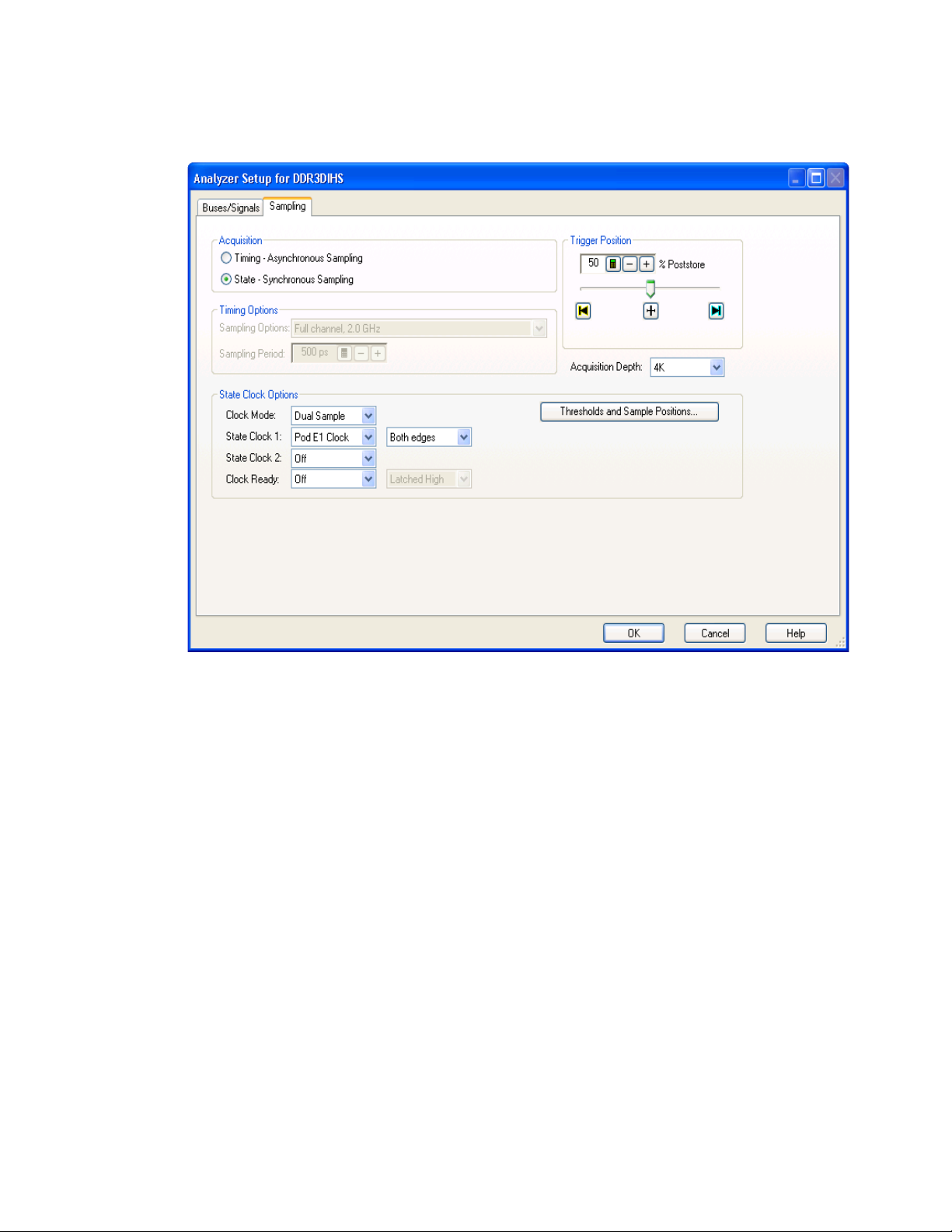
3In the Keysight Logic Analyzer application, click the Sampling Setup icon.
4 In the Sampling Setup dialog, click Thresholds and Sample Positions....
72 DDR Setup Assistant User Guide
Page 73
Setting Up Thresholds and Sample Positions on DDR Address/Control Signals 4
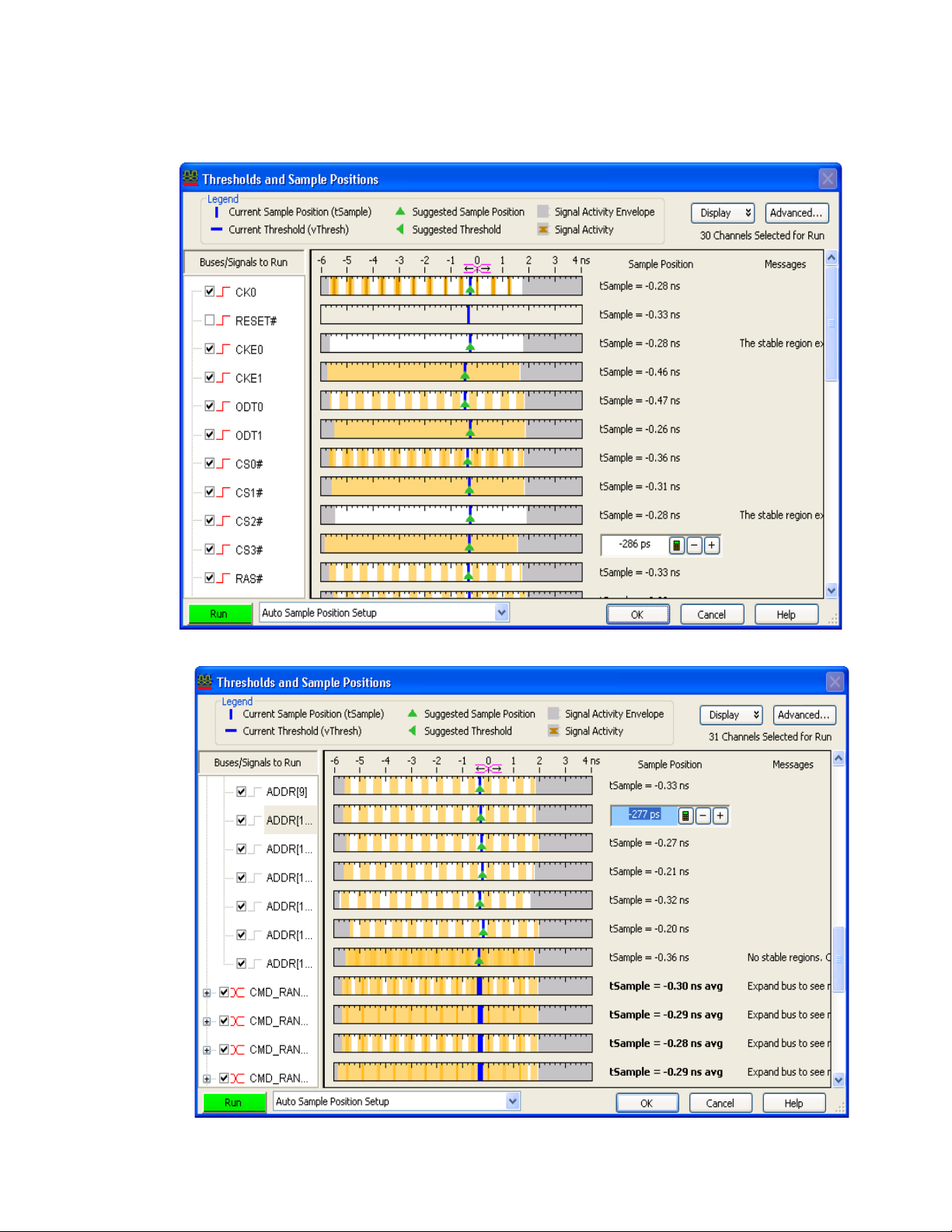
5 In the Thresholds and Sample Positions dialog, make sure the address and control signal sample
positions are aligned.
6 If necessary, click Run to rerun the Thresholds and Sample Positions set up.
The resulting sampling positions should be aligned and just left of zero (0).
DDR Setup Assistant User Guide 73
Page 74
4 Setting Up Thresholds and Sample Positions on DDR Address/Control Signals
74 DDR Setup Assistant User Guide
Page 75
Setting Up Thresholds and Sample Positions on DDR Address/Control Signals 4
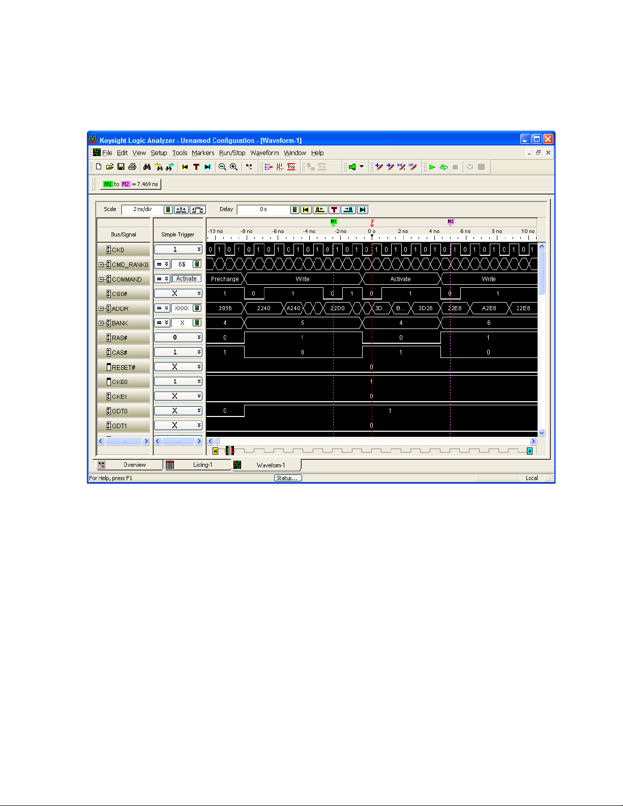
7 Take a trace to ensure that Command, CK, BANK, and ADDR are sampled correctly.
Because we are sampling on both the rising and falling edges of CK, you want to check that the
rising edge of CK must be in the middle of CS# low.
DDR Setup Assistant User Guide 75
Page 76
4 Setting Up Thresholds and Sample Positions on DDR Address/Control Signals
Solving Problems with Thresholds and Sample Positions Set Up
• “No eye finder or eye scan eyes for Address and Command" on page 76
• “Clock edges "too close together" error message on Run" on page 76
No eye finder or eye scan eyes for Address and Command
Possible Cause: Possible Solution:
The DDR device under test's
power saving mode allows
Address and Control signals
to float when CKE is low.
With 2T signaling, Address is
only valid while CS# is low.
Try these steps:
1 To verify the issue:
a In Timing mode, trigger on CKE = low.
b Check if the Address and Command signals appear to be tri-stated while CKE=low, that is,
there are rapid changes in signals during CKE=low relative to activity during CKE=high.
2 Disable Power saving mode in target BIOS until sample positions are set.
3 Or Clock Ready set to Enable High.
• Set Sample positions for Address/Ctrl to same position as CS#.
Clock edges "too close together" error message on Run
Possible causes and solutions:
Possible Cause: Possible Solution:
Poor signal integrity on clock
signal.
You are attempting to take a
trace from reset.
Power management (clocks
tri-state).
Check the clock signal quality by sampling the signal in timing mode, by using the logic analyzer
Thresholds and Sample Positions set up in state mode, or by using an oscilloscope.
In the sampling setup, set Clock Ready to latch high on CKE0.
Try these steps:
1 To verify the issue, in timing mode, Trigger on both CKE = low. Check if the clock appears to
stop or tri-state when both CKEs are low.
2 Change the CK0 threshold voltage setting from "differential" to 50 mV. This helps prevent the
Clock edge error message as CK0 fluctuates at 0 V during tri-state.
3 Or, disable Power Management mode in target BIOS.
4 Or, use Clock Ready set to Enable High. (For older interposers, this works for single rank DIMMs
if used on Dual Rank DIMMs. Some data from CKE1 rank could be lost when CKE0 is low when
CKE1 isn't low. Newer FuturePlus interposers OR the CKE0 and CKE1 signals which is good for
Dual and Quad Rank DIMMs.)
5 Or, consider using the 4 GHz (250 ps) half channel timing mode on Ad dr/Ctrl signals for power
management debug. You can also use the 8 GHz (125 ps) quarter channel timing mode, where
E5386A adapters are typically used to reduce the number of probes and connectors required.
76 DDR Setup Assistant User Guide
Page 77
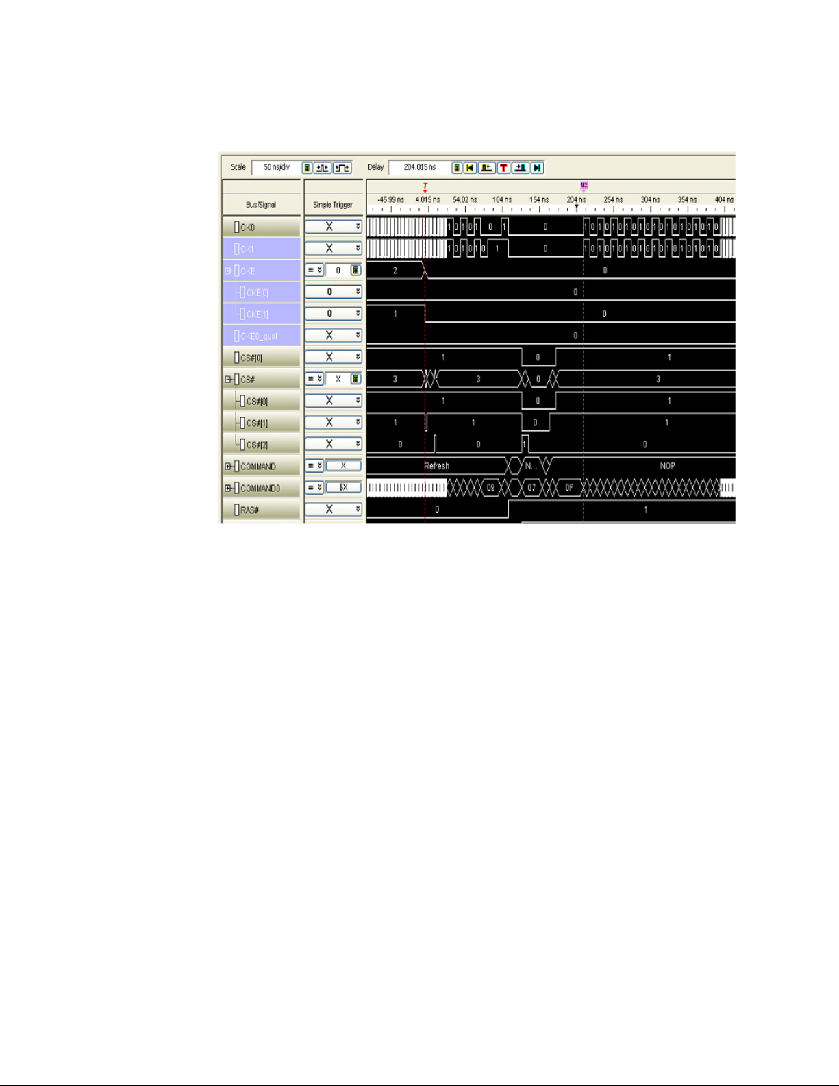
What to Expect if
Clocks Tri-State
Setting Up Thresholds and Sample Positions on DDR Address/Control Signals 4
When CKE and CKE1 are both low – system entering self refresh - clocks will turn off.
When the clock tri-states, the Waveform display will be different:
• Time tags will be wrong for approximately 40 cycles before and after the clock tri-states.
• However, sampled data is accurate.
• The DDR Bus Decoder decodes self refresh and power down modes.
• It is best to view the Listing display in this situation.
DDR Setup Assistant User Guide 77
Page 78

4 Setting Up Thresholds and Sample Positions on DDR Address/Control Signals
78 DDR Setup Assistant User Guide
Page 79

DDR Setup Assistant
NOTE
User’s Guide
5 Using DDR3 Eyefinder
Getting Started with DDR3 Eyefinder (for 16962A/16960A) / 80
Setting Scan Options / 91
Performing Scans / 97
Setting Sample Positions / 98
Viewing Signal Swing vs. Time / 103
Solving DDR3 Eyefinder Problems / 104
DDR3 Eyefinder is similar to the logic analyzer Thresholds and Sample Positions set up (also known
as normal logic analyzer eye finder) except that it is specifically designed to find DDR3 data signal
eyes, given the relationship between DDR3 control/address signals and data signals. DDR3 Eyefinder
also provides additional features to help you locate data signal eyes and properly set sample
positions, including the ability to analyze scan data using different scales, color schemes, and
filtering.
DDR3 Eyefinder can be used with the 16960A and 16962A logic analyzers. It cannot be used with
the 16950A/B logic analyzers.
DDR3 Eyefinder is unable to perform threshold scans when used with the 16960A logic analyzer,
and only time scans are available.
See Also • Logic analyzer Thresholds and Sample Positions set up ("To automatically adjust state sampling
positions and threshold voltages" (in the online help))
Page 80

5 Using DDR3 Eyefinder
Getting Started with DDR3 Eyefinder (for 16962A/16960A)
• “Before Running DDR3 Eyefinder" on page 80
• “Your First DDR3 Eyefinder Scan (16962A logic analyzers only)" on page 80
Before Running DDR3 Eyefinder
Before running DDR3 Eyefinder, you must set the sample positions for the control/address signals
using the DDR Setup Assistant (see “Using the DDR Setup Assistant" on page 35) or the logic
analyzer Thresholds and Sample Positions set up (also known as normal logic analyzer eyefinder, see
"To automatically adjust state sampling positions and threshold voltages" (in the online help)).
After setting the control/address signal sample positions, you can set up and run DDR3 Eyefinder
scans.
Your First DDR3 Eyefinder Scan (16962A logic analyzers only)
We recommend your first DDR3 Eyefinder scan be a "threshold" scan to give you a good first picture
of the signal eyes and proper sampling positions. This type of scan can take about an hour to
complete, but the results are worthwhile.
1 Go to the Keysight Logic Analyzer application.
2 If you are using the DDR Setup Assistant, you may have to click Cancel in the Panel Lock dialog.
3In the Keysight Logic Analyzer application, click the Overview tab (or the System Overview icon) to
view the Overview window.
4 In the DDR3 Eyefinder probe (in the column on the left), click the Eyefinder button.
80 DDR Setup Assistant User Guide
Page 81
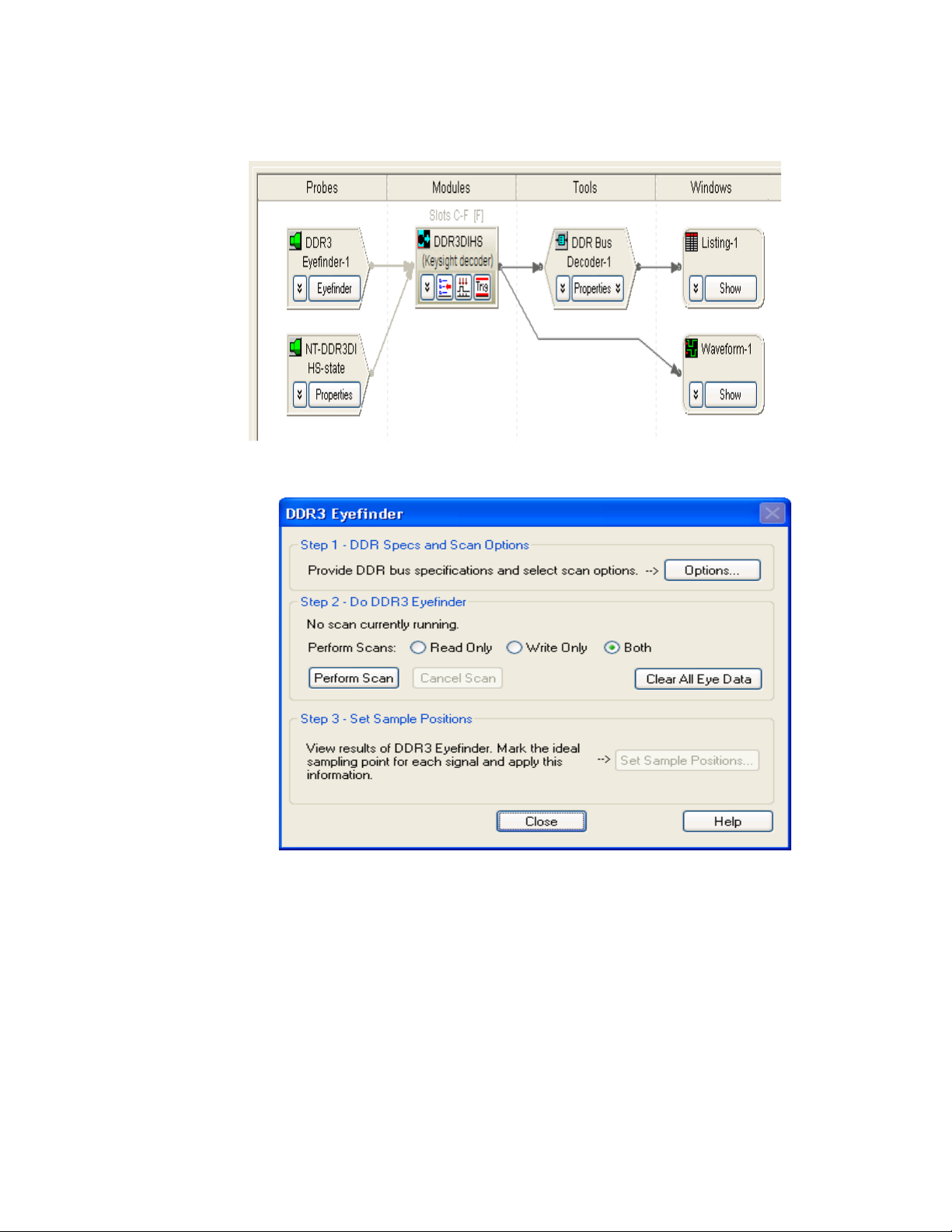
5 In the DDR3 Eyefinder dialog, first provide the scan values:
Using DDR3 Eyefinder 5
a Click Options....
b In the DDR Eyefinder Scan Options dialog's DDR Bus Specifications tab, enter the appropriate
Total Read Latency, Total Write Latency, Memory Configuration, and Burst Length values.
DDR Setup Assistant User Guide 81
Page 82
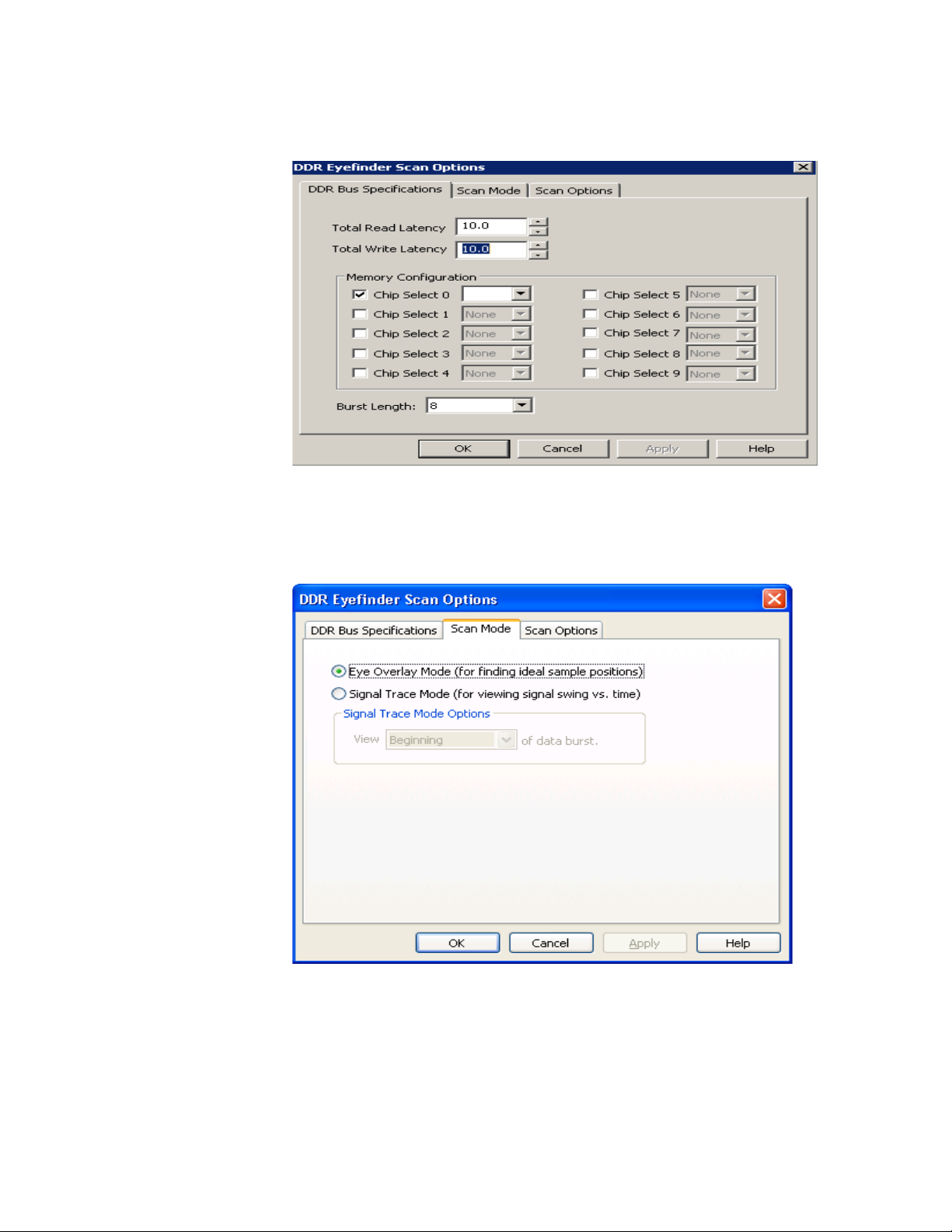
5 Using DDR3 Eyefinder
If you do not know the appropriate values for your device under test, you can find the
appropriate scan values using an Mode Register Settings (MRS) trigger as described in “Step -
Find Latency Values" on page 53 and “Setting Latency Values in DDR3 Eyefinder" on page 59.
c In the Scan Mode tab, use the recommended settings (eye overlay mode).
d In the Scan Options tab, use the recommended settings (time and threshold scan, medium
resolution, and full range).
82 DDR Setup Assistant User Guide
Page 83
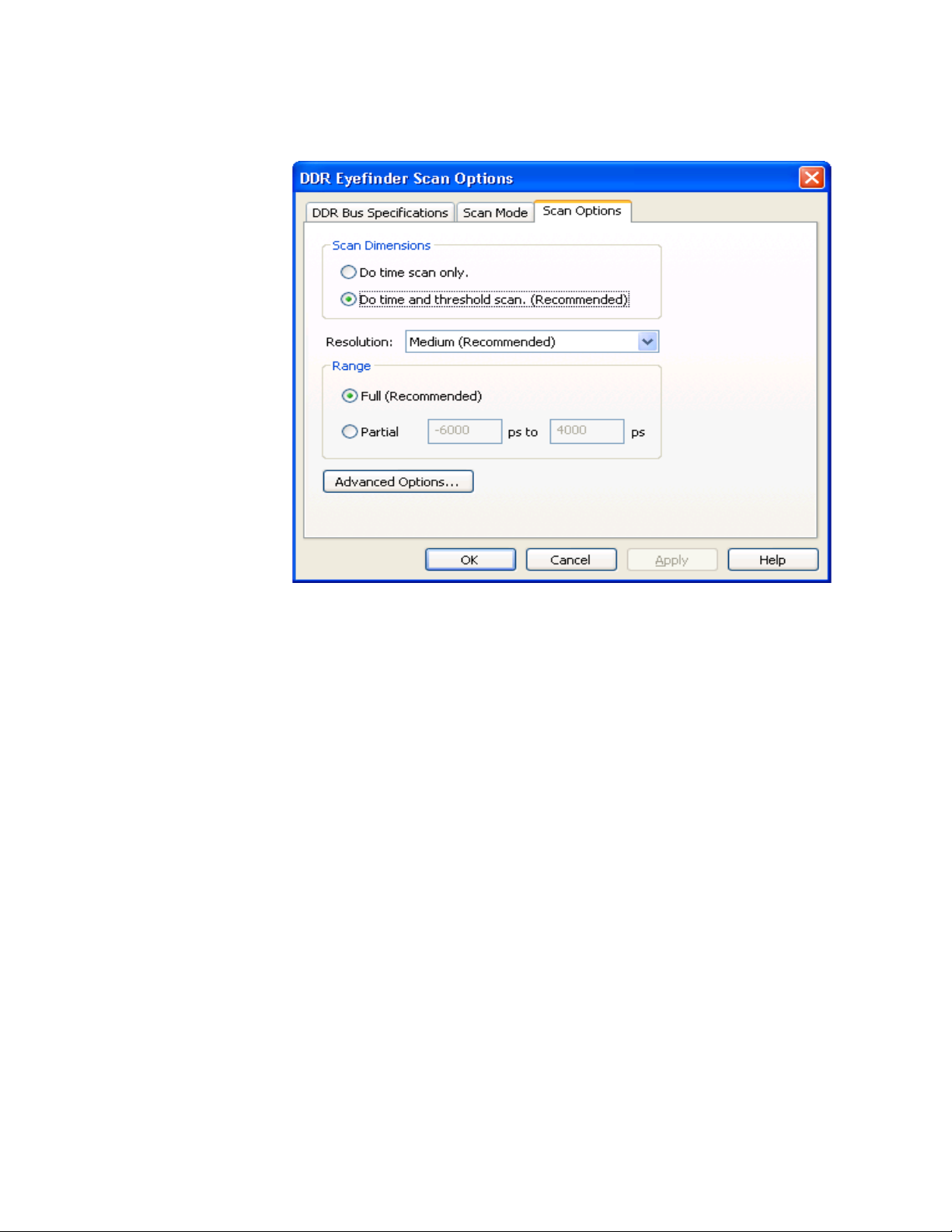
Using DDR3 Eyefinder 5
e Click OK to save the scan values/options and close the dialog.
For more information on setting scan values and options, see “Setting Scan Options" on page 91.
6 Back in the DDR3 Eyefinder dialog, select Both read and write scans; then, click Perform Scan to
run DDR3 Eyefinder scan.
As configured in the previous steps, the scan takes over an hour to complete. The DDR3 Eyefinder
run status is shown in the dialog.
DDR Setup Assistant User Guide 83
Page 84
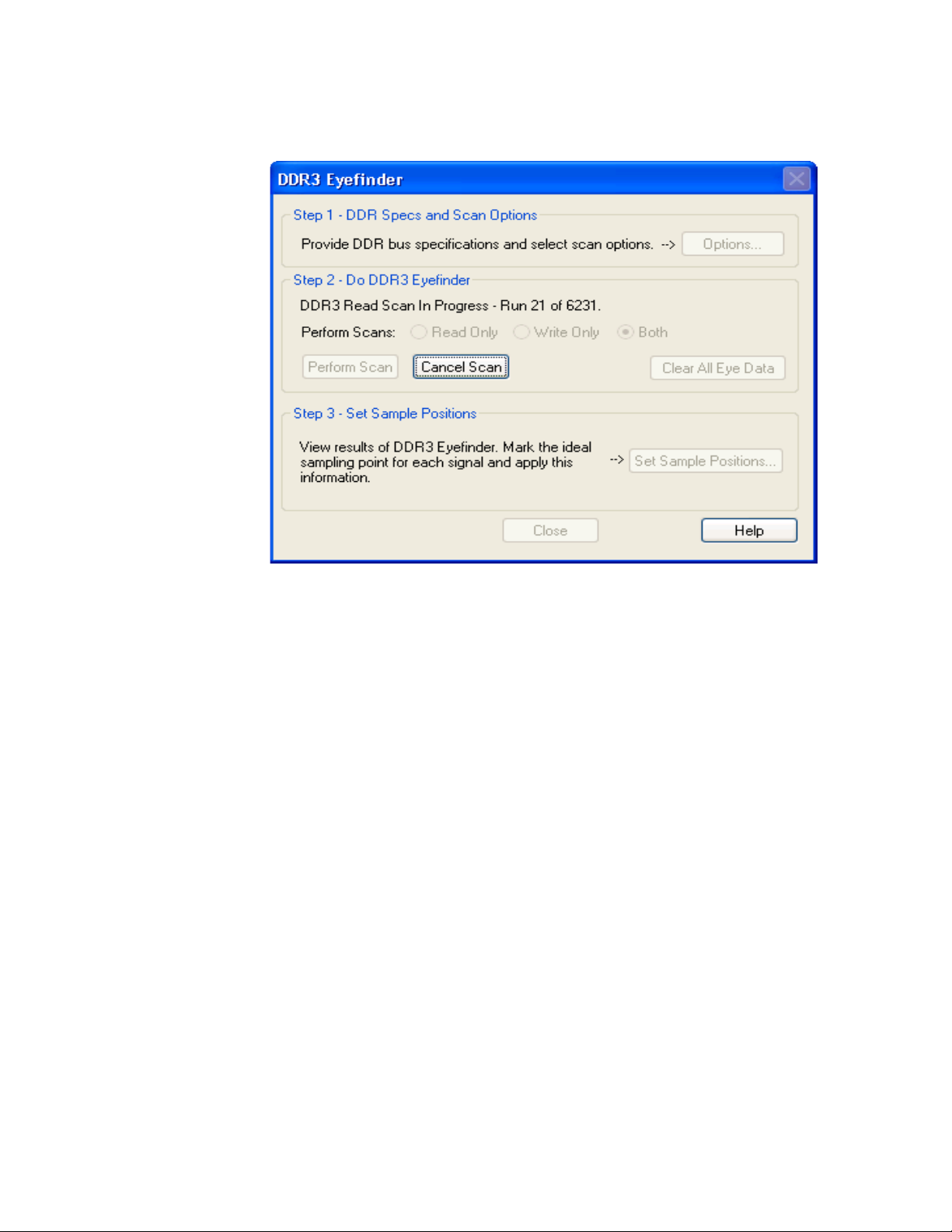
5 Using DDR3 Eyefinder
For more information on performing scans, see “Performing Scans" on page 97.
7 After the read and write scans complete, click Set Sample Positions... to view the scan results and
set the sample positions.
8 In the Set Sample Positions dialog:
84 DDR Setup Assistant User Guide
Page 85
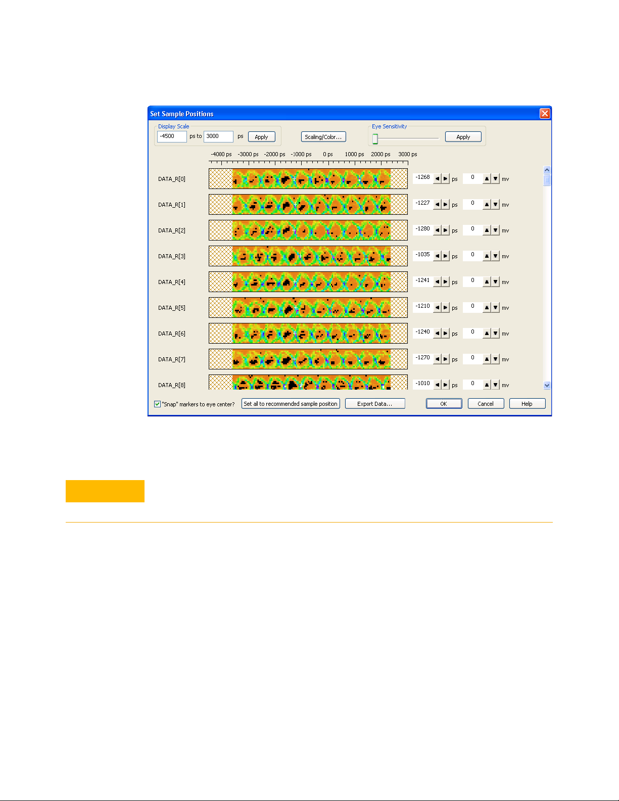
Using DDR3 Eyefinder 5
CAUTION
a Click Set all to recommended sample position.
The white crosshair markers show the recommended sample positions (see the following
example).
Recommended sample positions might be at incomplete eyes nearest the last sample position
settings. Always visually inspect the results of setting all to the recommended sample positions
(see the next step).
DDR Setup Assistant User Guide 85
Page 86
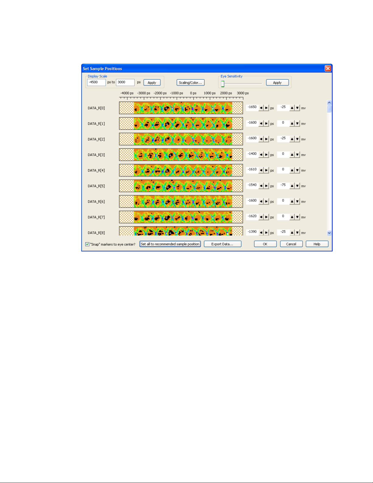
5 Using DDR3 Eyefinder
b Scroll though the signals and adjust sample positions as necessary. You can uncheck the
"Snap" markers to eye center? option for greater control over the sample position placement.
• Single-click to move to center of suggested eyes.
• When there is only one obvious eye, pick that eye.
• If there are problems, see “Solving DDR3 Eyefinder Problems" on page 104.
Take note of the eye positions for each group of eight signals. You may notice byte shifts on
eight bit boundaries as shown in the following example.
86 DDR Setup Assistant User Guide
Page 87
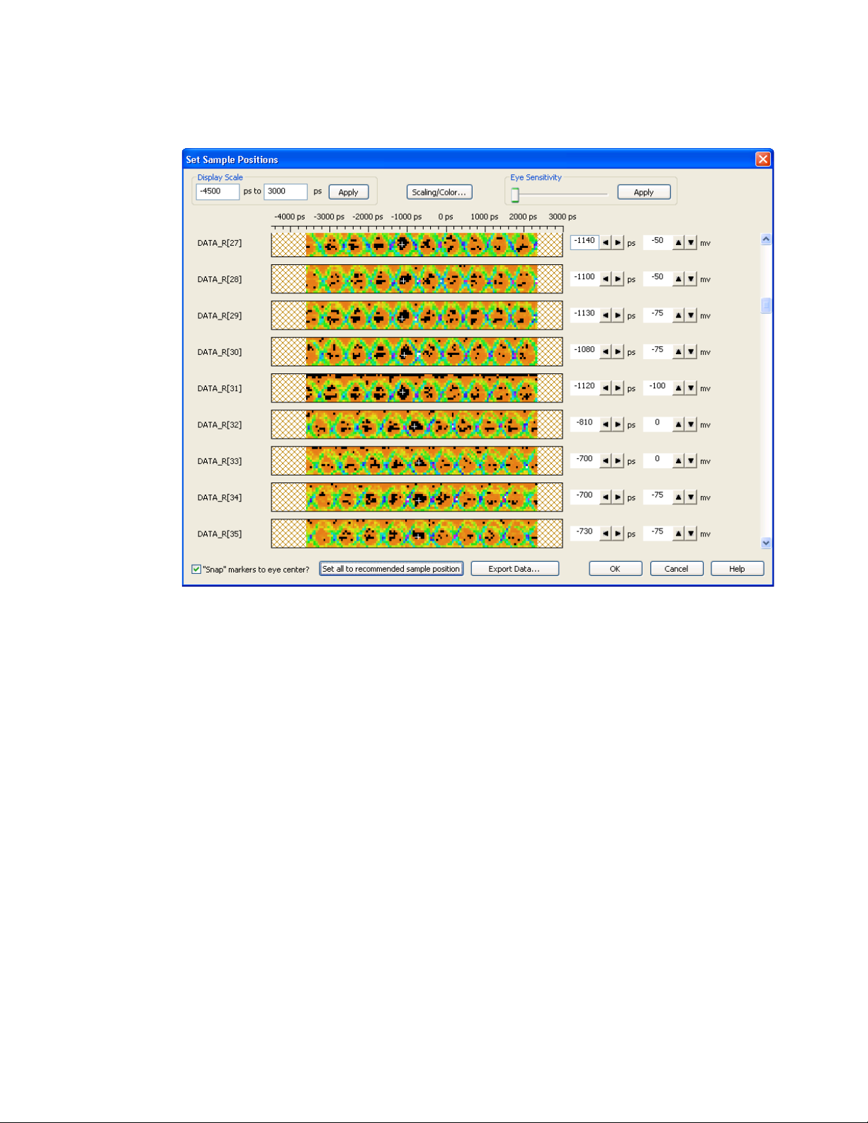
Using DDR3 Eyefinder 5
It's important to note the eye positions for each byte lane (set of eight signals) because the
strobe signal eyes are roughly at the same position as the corresponding byte lane. Knowing
this can help you select the correct eyes for the strobe signals. The following example shows
strobe eye position differences.
DDR Setup Assistant User Guide 87
Page 88
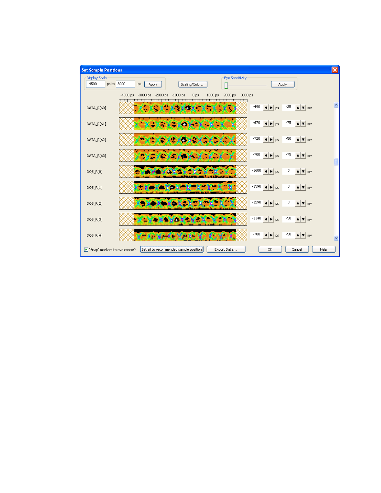
5 Using DDR3 Eyefinder
Data write signal eyes appear in different positions than data read signal eyes, as shown in the
following example.
88 DDR Setup Assistant User Guide
Page 89
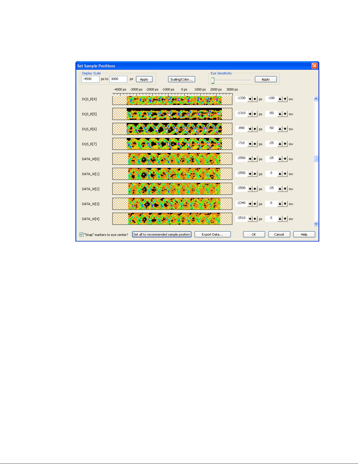
Using DDR3 Eyefinder 5
Sometimes for data read or write signals, two eyes appear. You can use the Do not store
back-to-back memory bursts advanced scan option to prevent this (see “Setting Advanced Scan
Options" on page 95). Higher resolution scans will also help clear up uncertainties.
You may notice signals that are not used, as in the following example.
DDR Setup Assistant User Guide 89
Page 90
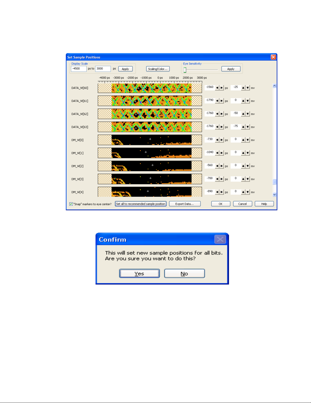
5 Using DDR3 Eyefinder
c When you are done setting sample positions, click OK. Then, click Yes in the confirmation
dialog.
d In the message dialog that says the sample positions have been successfully applied, click OK.
9Click Close to close the DDR3 Eyefinder dialog.
If you are running the DDR Setup Assistant, you have completed “Step - Set Sample Positions of
Data-related Signals (not applicable to U4154A/B logic analyzer)" on page 64. Return to the DDR
Setup Assistant, and continue with “Step - Save Setup" on page 68.
After running DDR3 Eyefinder to set sample positions for read and write signals, you are ready to
capture DDR3 traces with the logic analyzer.
See Also • “Setting Scan Options" on page 91
• “Performing Scans" on page 97
• “Setting Sample Positions" on page 98
• “Solving DDR3 Eyefinder Problems" on page 104
90 DDR Setup Assistant User Guide
Page 91
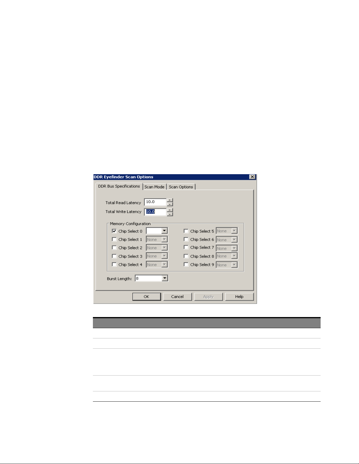
Setting Scan Options
The first step in using DDR3 Eyefinder is to set the scan values and options. In the DDR Eyefinder
Scan Options dialog, there are tabs for:
• “Setting DDR Bus Specifications" on page 91
• “Setting Scan Options" on page 93
• “Setting Scan Mode" on page 92
There is also a dialog for:
• “Setting Advanced Scan Options" on page 95
Setting DDR Bus Specifications
In the DDR Eyefinder Scan Options dialog's DDR Bus Specifications tab, you enter the basic
characteristics of the DDR bus.
Using DDR3 Eyefinder 5
Field Description
Total Read Latency The total number of clock cycles from the valid Read command to valid data.
Total Write Latency The total number of clock cycles from the valid Write command to valid data.
Note: The latency values that you specify here represent the total latency for your system and therefore should include parameters
that affect total latency. For instance, if your system has Additive Latency (AL), then you must include it in the Total Latency values.
Similarly, if tDQSS or tDQSCK parameters are greater than one full clock cycle, then you must add these values (rounded to the
nearest integer) in the Total Latency values.
Memory Configuration Make the appropriate Memory Configuration selections based on the chip selects used
Burst Length This is the number of words read or written for each read/write command.
DDR Setup Assistant User Guide 91
in the device under test.
Page 92
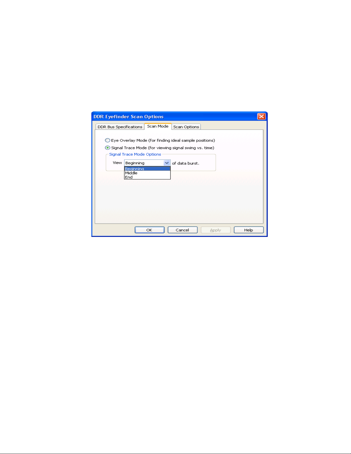
5 Using DDR3 Eyefinder
Setting Scan Mode
You can find the appropriate values for Total Read Latency, Total Write Latency, and Burst Length using an
Mode Register Settings (MRS) trigger as described in “Step - Find Latency Values" on page 53 and
“Setting Latency Values in DDR3 Eyefinder" on page 59.
In the DDR Eyefinder Scan Options dialog's Scan Mode tab, you can specify the scan mode.
92 DDR Setup Assistant User Guide
Page 93
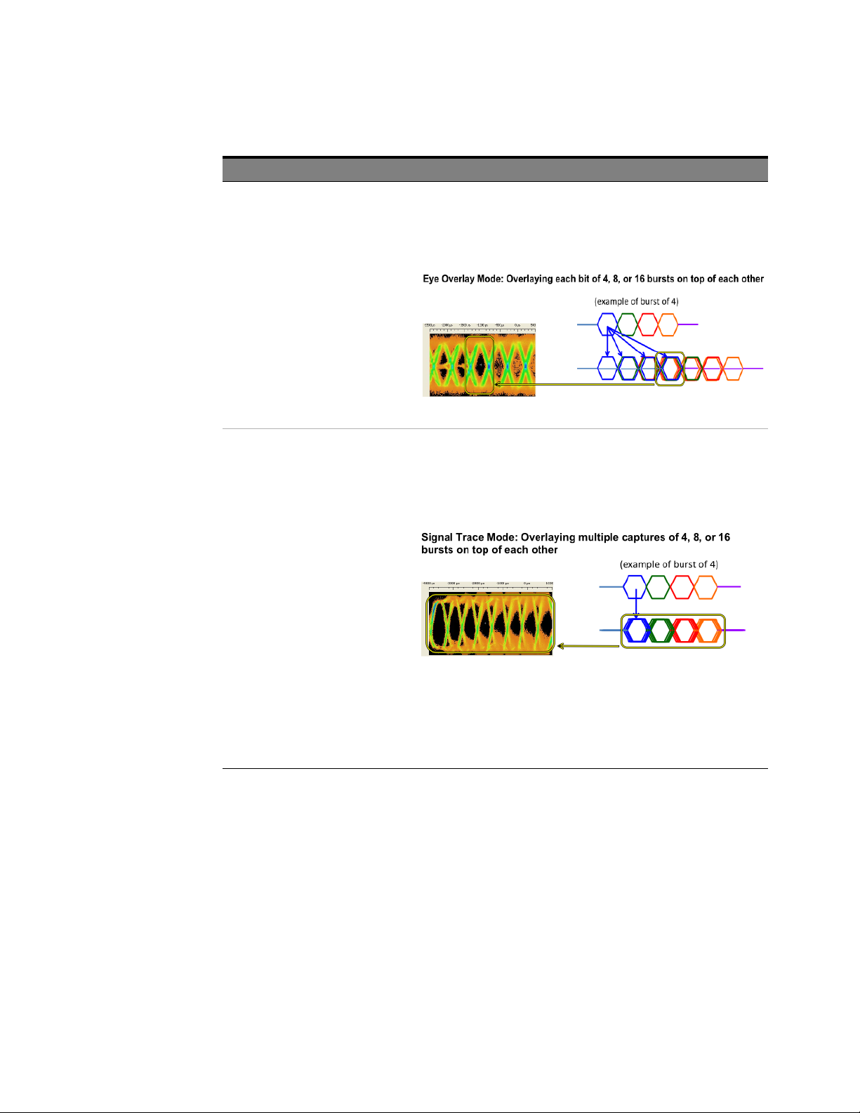
Scan Mode Use
Using DDR3 Eyefinder 5
Eye Overlay Mode Use this mode when setting sample positions for data signals.
Signal Trace Mode Use this mode for viewing signal swing vs. time. Al though sample positions can be
In this mode, DDR3 Eyefinder overlays the eyes for each bit in a burst in order to show a
composite eye, without tri-state or noise, that helps you locate the best sample
position.
checked and modified in this mode, it is generally not recommended.
In this mode, DDR3 Eyefinder overlays complete bursts in order to provide additional
qualitative insight into the signal integrity on the DDR system at the logic analyzer
probe location.
When the Signal Trace Mode is selected, you can select from these data burst areas to
view:
• Beginning— Scans are made at the beginning of a data burst.
• Middle— Scans are made at the middle of the data burst.
•End— Scans are made at the end of the data burst.
For more information, see
“Viewing Signal Swing vs. Time" on page 103.
Setting Scan Options
In the DDR Eyefinder Scan Options dialog's Scan Options tab, you can specify the scan type, the
scan resolution, and the scan range.
DDR Setup Assistant User Guide 93
Page 94
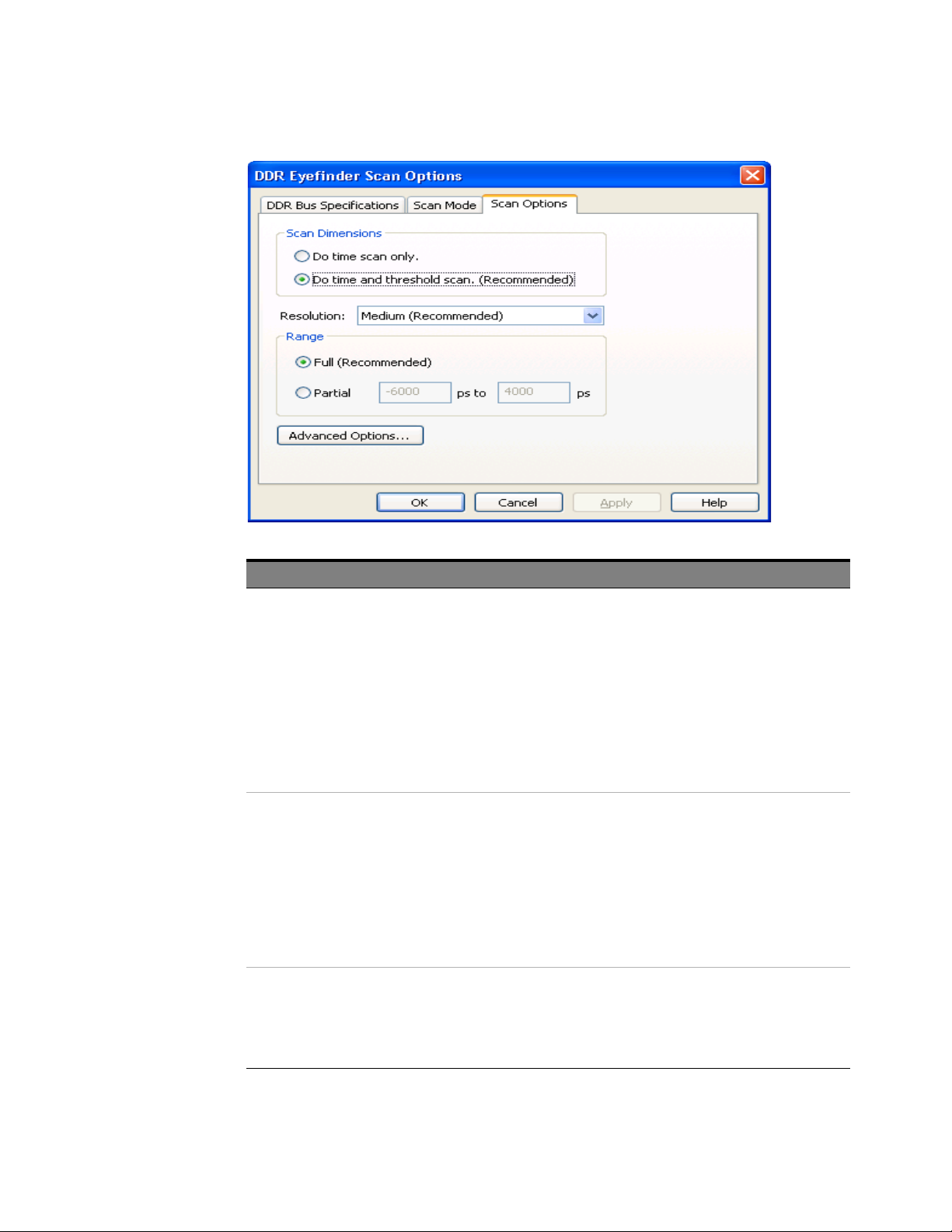
5 Using DDR3 Eyefinder
Scan Options Application/Use
Scan Type Time scans d ivide the sample position time range into "buckets". During the scan, many
Resolution You can select from these resolutions:
Range Full performs the scan over the full sample position time range.
samples are taken at different signal delay settings (and one threshold voltage), and the
number of signal transitions that occur in the buckets is recorded. When the scan
completes, buckets that have a greater number of transitions are colored brighter or
with more intensity than buckets with fewer transitions. Buckets with no transitions
have no color. This gives you a picture of where signal crossing points occur and can tell
you where to set sample positions. Time scans are done at a single threshold voltage
setting and provide the fastest scan for setting sample positions.
Time and threshold scans divide time buckets vertically into voltage range buckets.
During the scan, different threshold voltage settings are used as well as different delay
settings. The scan resul ts show more signal detail and help you better identify eyes and
proper sampling positions. Threshold scans take longer because they scan voltages as
well as time.
• Ultra Fine (Slowest)— 5 ps time, 5 mV threshold resolution — uses the most
buckets, and the scan takes longest to run.
• Fine— 10 ps time, 10 mV threshold resolution — uses many buckets, and the scan
takes longer to run.
• Medium-Fine— 25 ps time, 20 mV threshold resolution — uses setting between Fine
and Medium.
• Medium (Recommended)— 50 ps time, 50 mV threshold resolution — uses an
intermediate number of buckets and results in an intermed iate scan time.
• Coarse (Fastest)— 50 ps time, 75 mV threshold resolution — uses fewer buckets,
and scans complete in a shorter amount of time.
Partial lets you narrow the time range and perform faster scans. However, be careful
when changing these values. If you scan too short a time range, you could miss the
proper signal eyes.
Generally, you use this option when there is a portion of a signal you want to view in
more detail and you want to shorten the time it takes the scan to run.
See Also • “Setting Advanced Scan Options" on page 95
94 DDR Setup Assistant User Guide
Page 95
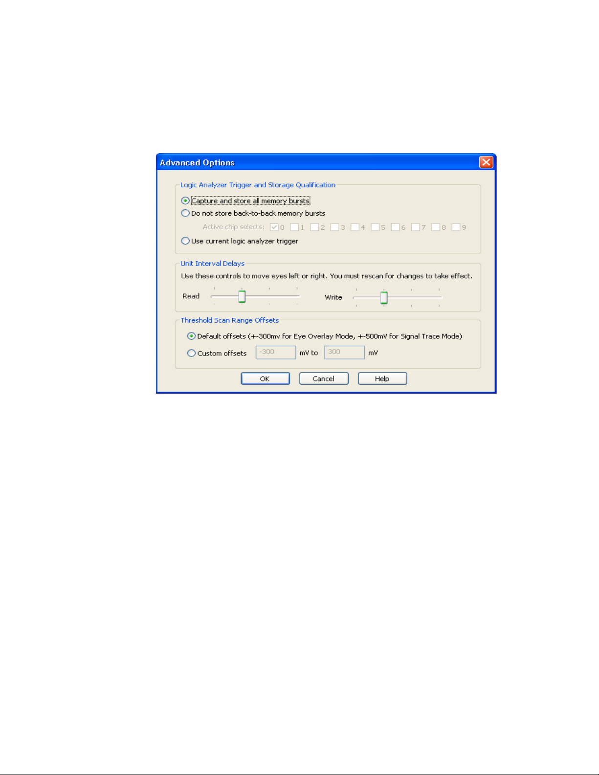
Using DDR3 Eyefinder 5
Setting Advanced Scan Options
In the DDR Eyefinder Scan Options dialog's Scan Options tab, you can click Ad vanced Options... to
change advanced scan options.
DDR Setup Assistant User Guide 95
Page 96

5 Using DDR3 Eyefinder
Field Description
Logic Analyzer Trigger and Storage
Qualification
Unit Interval Delays If the eyes in which you want to set the sampl ing position are outside of the adjustment
Capture and store all memory bursts — this is the default setting.
Do not store back-to-back memory bursts — you can use this to eliminate the "double
eye" effect in scan results.
Use current logic analyzer trigger — this lets you further customize the samples that are
used in scans.
range, you can use these "coarse delay" ad justments to move the signals left or right (in
relation to the zero time) by Unit Interval (clock cycle) amounts.
It is unlikely that you will have to change the unit interval delays when using the proper
configuration files and Total Read Latency and Total Write Latency settings.
After making coarse delay ad justments, you must rescan and set the sampling positions
again.
Background: There are two ways to move the DDR3 Eyefinder display window and scan
the appropriate location for the Read and Write data valid windows:
1 By adjusting the Total Read Latency setting for the Read eyes and Total Write
Latency for the Write eyes. See “Setting DDR Bus Specifications" on page 91.
2 By adjusting the Unit Interval Delays sliders. In the extreme right position, the delay
is zero between the qualified clock edge and the data. Each mark to the left
represents a whole clock cycle. The Unit Interval Delays sliders are usually used
only for two scenarios:
• When setting up a new configuration for a new probe or embedded midbus
application where delays from the routing require adjustment in the DDR3
Eyefinder display.
• When adjusting for significant changes in the data rate compared to the range
of the specification for a specific configuration. For instance, most DDR3 probes
are set up expecting DDR 3 800-1600.
Moving the slider to the left results in the data eyes moving left in the display after
rerunning a scan. If the slider is all the way to the right and the data eyes need to move
further to the right, reduce the Total Read Latency and Total Write Latency settings in
the DDR3 Eyefinder tool. Once you determine the correct Latency settings to capture
the data eyes, use the same latency values in the DDR Bus Decoder.
Threshold Scan Range Offsets Lets you specify a custom vertical range to use for threshold scans. This option lets you
either:
• See a portion of a signal in more detail (and shorten the scan time).
• See more of the signal swing (and lengthen the scan time).
Note that the default offsets are different depend ing on the selected Scan Mode.
96 DDR Setup Assistant User Guide
Page 97
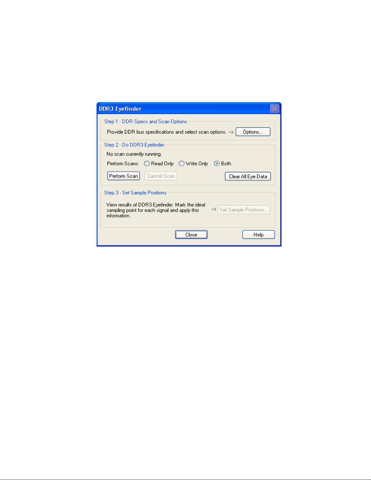
Performing Scans
Using DDR3 Eyefinder 5
When performing DDR3 Eyefinder scans, you can perform read only scans or write only scans, you
can cancel scans, and you can clear eye data.
To run scans 1Click Perform Scan to start a scan using the currently set options (see “Setting Scan Options" on
page 91).
To select Read
Only, Write Only,
• If you are only interested in setting the sample positions of data read or data write signals, you can
choose Read Only or Write Only.
or Both read and
write scans
To cancel a scan 1Click Cancel Scan to stop a currently running scan.
To clear all eye
1Click Clear All Eye Data to clear all DDR3 Eyefinder scan data.
data
DDR Setup Assistant User Guide 97
Page 98
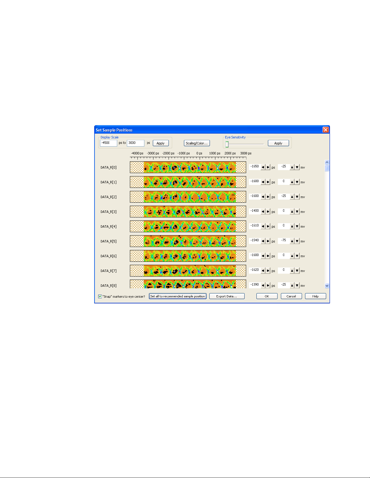
5 Using DDR3 Eyefinder
Setting Sample Positions
After performing DDR3 Eyefinder scans, when setting sample positions, you can change the display
settings to help identify the proper eye locations, and you can adjust the recommended sample
positions.
To do this, click Set Sample Positions... in the DDR3 Eyefinder dialog. This opens the Set Sample
Positions dialog.
The Set Sample Positions dialog gives you these capabilities:
• “Adjusting the Display Scale" on page 98
• “Changing the Time Bucket Scaling and Colors" on page 99
• “Adjusting the Eye Sensitivity" on page 100
• “Adjusting Sample Positions" on page 101
The Export Data...button lets you export the underlying eye scan data to a CSV format file that can be
imported into Microsoft Excel or other data visualization tools. For more information on the format of
the exported CSV data, please contact your local Keysight sales representative.
Adjusting the Display Scale
In the upper left corner of the Set Sample Positions dialog, there is a Display Scale box for adjusting
the scale of the display. This lets you zoom in on a particular eye(s) or zoom out to the full scale of
the data that was scanned. After you enter the desired values of the range, click Apply.
98 DDR Setup Assistant User Guide
Page 99
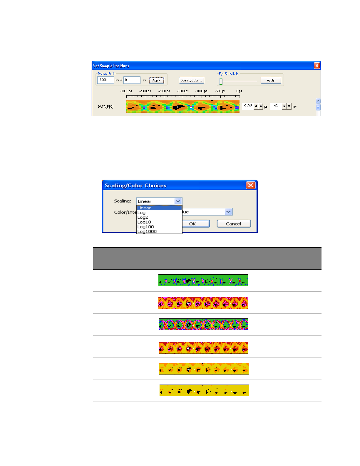
Changing the Time Bucket Scaling and Colors
To change the time bucket scaling and color/intensity settings in the Set Sample Positions dialog:
1Click Scaling/Color....
2 In the Scaling/Color Choices dialog, select the Scaling drop-down and choose the desired
scaling:
Using DDR3 Eyefinder 5
Scaling: Example Notes
Linear (Color graded)
Log (Color graded)
Log2 (Golor graded)
Log10 (Color graded)
Log100 (Color graded)
Log1000 (Color graded)
3 In the Scaling/Color Choices dialog, select the Color/Intensity drop-down and choose the desired
color scheme or intensity:
DDR Setup Assistant User Guide 99
Page 100
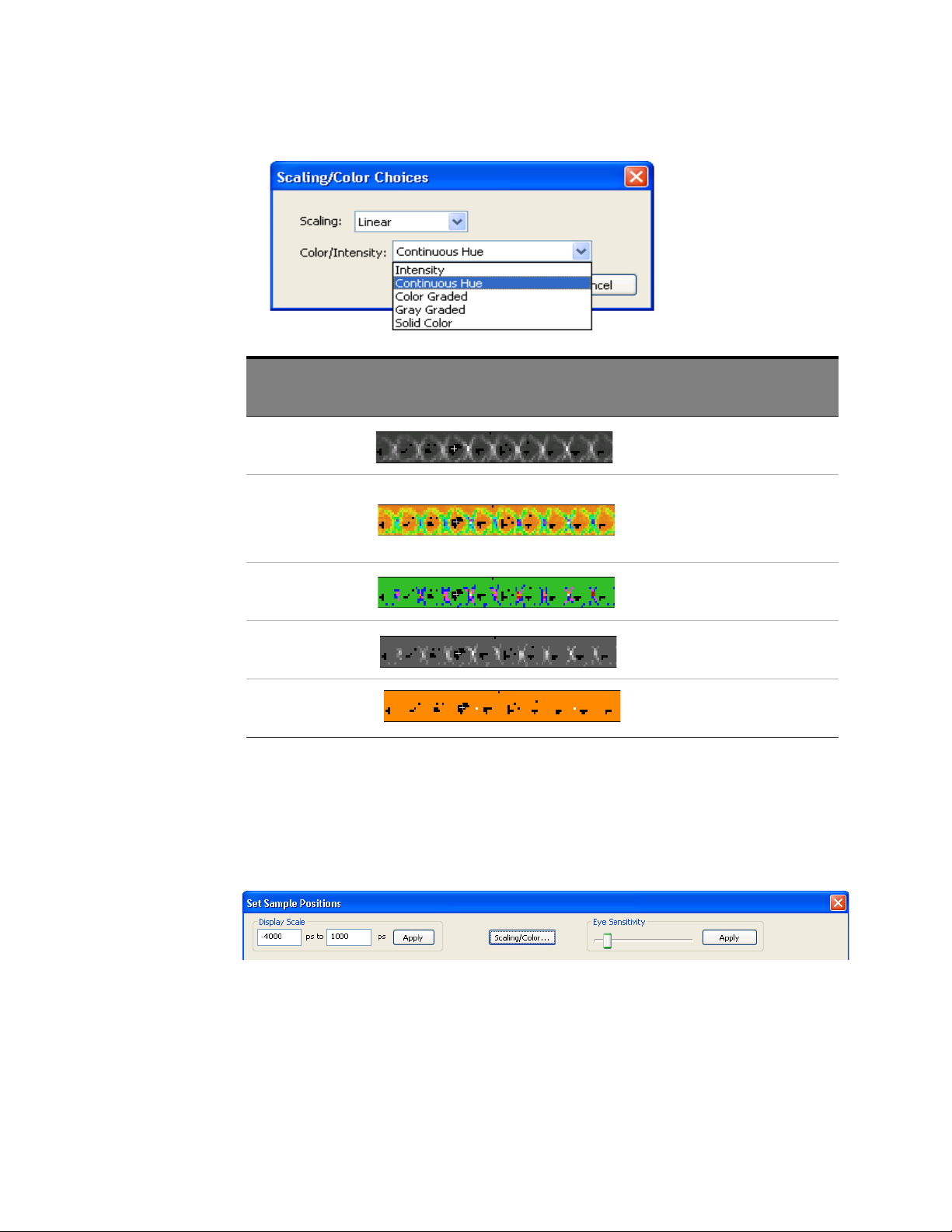
5 Using DDR3 Eyefinder
Color/Intensity: Example Notes
Intensity (Linear scaling)
Continuous Hue (Linear scaling)
Color Graded (Linear scaling)
Gray Graded (Linear scaling)
Solid Color (Linear scaling)
4Click OK to make the scaling color change.
Adjusting the Eye Sensitivity
To adjust the eye sensitivity in the Set Sample Positions dialog:
1Drag the Eye Sensitivity slider; then, click Apply.
Continuous hue appears the same for all
Log scales.
Changing the sensitivity does not affect any of the collected data, it just hides lower intensity values
so that you can more easily identify the signal eyes.
Some examples of decreased sensitivity are shown in the following table.
100 DDR Setup Assistant User Guide
 Loading...