

Page 1

Programmer’s Guide
Publication number 01660-97024
First edition, November 1997
For Safety information, Warranties, and Regulatory
information, see the pages behind the Index.
Copyright Hewlett-Packard Company 1992-1997
All Rights Reserved
HP 1660C/CS/CP-Series Logic
Analyzers
Page 2

ii
Page 3
In This Book
Introduction to Programming the
1
HP 1660C/CS/ CP
This programmer’s guide contains general
information, instrument level commands,
logic analyzer commands, oscilloscope
module commands, pattern generator
module commands, and programming
examples for the HP 1660C/CS/CP-Series
Logic Analyzers. This guide focuses on
how to program the instrument over the
HP-IB and the RS-232-C interfaces. For
information on the Ethernet, refer to the
LAN User’s Guide.
Instruments covered by the
HP 1660C/CS/CP-Series
Programmers Guide
The HP 1660C/CS/CP-Series Logic
Analyzers are available with or without
oscilloscope measurement capabilities.
The HP 1660C-series contains only a logic
analyzer. The HP 1660CS-series contains
both a logic analyzer and a digitizing
oscilloscope. The HP 1660CP-series
contains both a logic analyzer and a
pattern generator. The HP
1660C/CS/CP-series differs from the HP
1660A/AS-series in having a hard disk
drive and optional Ethernet capability.
2
3
4
5
6
7
8
9
10
11
12
Programming Over HP-IB
Programming Over RS-232-C
Programming and
Documentation Conventions
Message Communica ti on
and System Functions
Status Reporting
Error Message
Common Commands
Instrument Commands
SYSTem Subsystem
MMEMory Sub system
INTermodule Subsystem
What is in the
HP1660C/CS/CP-Series
Programmer’s Guide?
The HP1660C/CS/CP-Series
Programmer’s Guide is organized in six
parts.
13
14
MACHine Subsystem
WLISt Subsystem
iii
Page 4

Part 1 Part 1 consists of chapters 1 through 7 and contains general
information about programming basics, HP-IB and RS-232-C interface
requirements, documentation conventions, status reporting, and error
messages.
If you are already familiar with IEEE 488.2 programming and HP-IB or
RS-232-C, you may want to just scan these chapters. If you are new to
programming the system, you should read part 1.
Chapter 1 is divided into two sections. The first section, "Talking to the
Instrument," concentrates on program syntax, and the second section,
"Receiving Information from the Instrument," discusses how to send queries
and how to retrieve query results from the instrument.
Read either chapter 2, "Programming Over HP-IB," or chapter 3,
"Programming Over RS-232-C" for information concerning the physical
connection between the HP 1660C/CS-Series Logic Analyzer and your
controller.
Chapter 4, "Programming and Documentation Conventions," gives an
overview of all instructions and also explains the notation conventions used
in the syntax definitions and examples.
Chapter 5, "Message Communication and System Functions," provides an
overview of the operation of instruments that operate in compliance with the
IEEE 488.2 standard.
Chapter 6 explains status reporting and how it can be used to monitor the
flow of your programs and measurement process.
Chapter 7 contains error message descriptions.
Part 2 Part 2, chapters 8 through 13, explains each command in the
command set for the overall logic analyzer. These chapters are organized
in subsystems with each subsystem representing a front-panel menu.
The commands explained in this part give you access to common commands,
instrument commands, system level commands, disk commands, and
intermodule measurement commands. This part is designed to provide a
concise description of each command.
Part 3 Part 3, chapters 14 through 27 explain each command in the
subsystem command set for the logic analyzer. Chapter 27 contains
information on the SYSTem:DATA and SYSTem:SETup commands for
the logic analyzer.
The commands explained in this part give you access to all the commands
used to operate the logic analyzer portion of the HP 1660C/CS/CP-Series
iv
Page 5
15
SFORmat Subsy stem
system. This part is designed to provide
a concise description of each command.
Part 4 Part 4, chapters 28 through 36
explain each command in the subsystem
command set for the oscilloscope. The
information covered in Part 4 is only
relevant to models containing an
oscilloscope.
The commands explained in this part give
you access to all the commands used to
operate the oscilloscope portion of the
HP 1660CS-series system. This part is
designed to provide a concise description
of each command.
Part 5 Part 5, chapters 37 through 42
explain each command in the subsystem
command set for the pattern generator.
The information covered in Part 5 is only
relevant to models containing a pattern
generator.
The commands explained in this part give
you access to all the commands used to
operate the pattern generator portion of
the HP 1660CP-series system. This part
is designed to provide a concise
description of each command.
STRigger (STRace) Subsystem
16
17
18
19
20
21
22
23
24
25
SLISt Subsystem
SWAVeform Subsystem
SCHart Subsystem
COMPare Subsystem
TFORmat Subsystem
TRIGger {TRACe} Subsystem
TWAVeform Subsystem
TLISt Subsyste m
SPA Subsystem
26
27
28
29
SYMbol Subsystem
DATA and SETup Commands
Oscilloscope Root Level
Commands
ACQuire Subsystem
v
Page 6

Part 6 Part 6, chapter 43, contains program examples of actual tasks
that show you how to get started in programming the HP
1660C/CS/CP-Series Logic Analyzers. The complexity of your programs
and the tasks they accomplish are limited only by your imagination.
These examples are written in HP BASIC 6.2; however, the program
concepts can be used in any other popular programming language that
allows communications over HP-IB or RS-232buses.
vi
Page 7
30
CHANnel Subsystem
31
32
33
34
35
36
37
38
39
DISPlay Subsystem
MARKer Subsystem
MEASure Subsyste m
TIMebase Subsystem
TRIGger Subsystem
WAVeform Subs ystems
Programing the Pattern Generator
FORMat Sub system
SEQuence Subsystem
40
41
42
43
MACRo Subsystem
SYMBol Subsystem
DATA and SETup Commands
Programming Examples
Index
vii
Page 8

viii
Page 9

Part 1
General Information
Page 10

Page 11

1
Introduction to Programming the HP 1660C/CS/CP
Page 12

Introduction
This chapter introduces you to the basics of remote programming, and
is organized in two sections. The first section, "Talking to the
Instrument," concentrates on initializing the bus, program syntax and
the elements of a syntax instuction. The second section, "Receiving
Information from the Instrument," discusses how queries are sent and
how to retrieve query results from the mainframe instruments.
The programming instructions explained in this book conform to
IEEE Std 488.2-1987, "IEEE Standard Codes, Formats, Protocols, and
Common Commands." These programming instructions provide a
means of remotely controlling the HP 1660C/CS/CP-series logic
analyzers. There are three general categories of use. You can:
• Set up the instrument and start measurements
• Retrieve setup information and measurement results
• Send measurement data to the instrument
The instructions listed in this manual give you access to the
measurements and front panel features of the HP 1660C/CS/CP-series.
The complexity of your programs and the tasks they accomplish are
limited only by your imagination. This programming guide is designed
to provide a concise description of each instruction.
1–2
Page 13

Talking to the Instrument
In general, computers acting as controllers communicate with the
instrument by sending and receiving messages over a remote
interface, such as HP-IB or RS-232-C. Instructions for programming
the HP 1660C/CS/CP-series will normally appear as ASCII character
strings embedded inside the output statements of a "host" language
available on your controller. The host language’s input statements are
used to read in responses from the HP 1660C/CS/CP-series.
For example, HP 9000 Series 200/300 BASIC uses the OUTPUT
statement for sending commands and queries to the HP
1660C/CS/CP-series logic analyzers. After you send a query, you can
read the response using the ENTER statement. All programming
examples in this manual are presented in HP BASIC.
Example This BASIC statement sends a command that causes the logic
analyzer’s machine 1 to be a state analyzer:
OUTPUT XXX;":MACHINE1:TYPE STATE" <terminator>
Each part of this BASIC statement is explained in this section.
1–3
Page 14

Introduction to Programming the HP 1660C/CS/CP
Initialization
Initialization
To make sure the bus and all appropriate interfaces are in a known state,
begin every program with an initialization statement. BASIC provides a
CLEAR command that clears the interface buffer. If you are using HP-IB,
CLEAR will also reset the parser in the logic analyzer. The parser is the
program resident in the logic analyzer that reads the instructions you send to
it from the controller.
After clearing the interface, you could preset the logic analyzer to a known
state by loading a predefined configuration file from the disk.
Refer to your controller manual and programming language reference manual
for information on initializing the interface.
Example This BASIC statement would load the configuration file "DEFAULT " (if it
exists) into the logic analyzer.
OUTPUT XXX;":MMEMORY:LOAD:CONFIG ’DEFAULT ’"
Refer to chapter 11, "MMEMory Subsystem" for more information on the
LOAD command.
Example This program demonstrates the basic command structure used to program
the HP 1660C/CS/CP/ cp-series logic analyzers.
10 CLEAR XXX !Initialize instrument interface
20 OUTPUT XXX;":SYSTEM:HEADER ON"!Turn headers on
30 OUTPUT XXX;":SYSTEM:LONGFORM ON" !Turn longform on
40 OUTPUT XXX;":MMEM:LOAD:CONFIG ’TEST E’" !Load configuration file
50 OUTPUT XXX;":MENU FORMAT,1" !Select Format menu for machine 1
60 OUTPUT XXX;":RMODE SINGLE" !Select run mode
70 OUTPUT XXX;":START" !Run the measurement
1–4
Page 15
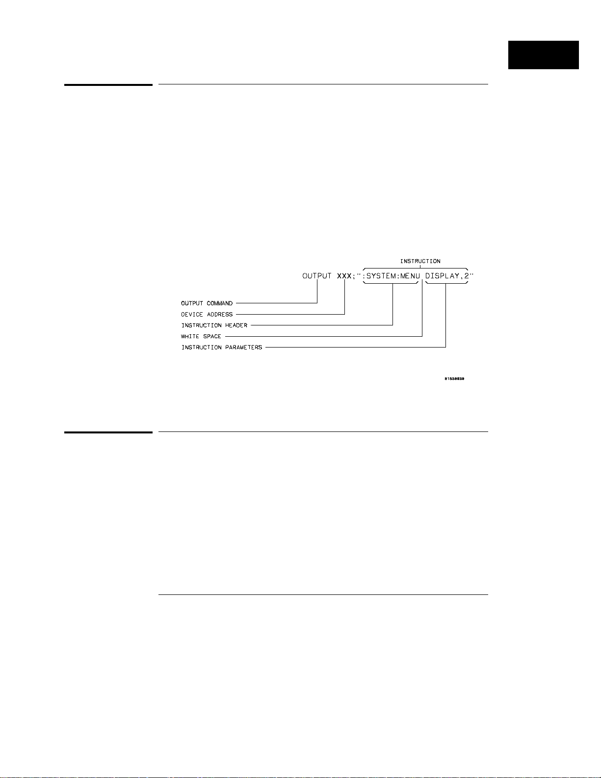
Figure 1-1
Introduction to Programming the HP 1660C/CS/CP
Instr uction Syntax
Instruction Syntax
To program the logic analyzer remotely, you must understand the command
format and structure. The IEEE 488.2 standard governs syntax rules
pertaining to how individual elements, such as headers, separators,
parameters and terminators, may be grouped together to form complete
instructions. Syntax definitions are also given to show how query responses
will be formatted. Figure 1-1 shows the three main syntactical parts of a
typical program statement: Output Command, Device Address, and
Instruction. The instruction is further broken down into three parts:
Instruction header, White space, and Instruction parameters.
Program Message Syntax
Output Command
The output command depends on the language you choose to use.
Throughout this guide, HP 9000 Series 200/300 BASIC 6.2 is used in the
programming examples. If you use another language, you will need to find
the equivalents of Basic Commands, like OUTPUT, ENTER and CLEAR to
convert the examples. The instructions are always shown between the
double quotation marks.
1–5
Page 16

Introduction to Programming the HP 1660C/CS/CP
Device Address
Device Address
The location where the device address must be specified also depends on the
host language that you are using. In some languages, this could be specified
outside the output command. In BASIC, this is always specified after the
keyword OUTPUT. The examples in this manual use a generic address of
XXX. When writing programs, the number you use will depend on the cable
you use, in addition to the actual address. If you are using an HP-IB, see
chapter 2, "Programming over HP-IB." If you are using RS-232-C, see
chapter 3, "Programming Over RS-232-C."
Instructions
Instructions (both commands and queries) normally appear as a string
embedded in a statement of your host language, such as BASIC, Pascal or C.
The only time a parameter is not meant to be expressed as a string is when
the instruction’s syntax definition specifies block data. There are just a few
instructions that use block data.
Instructions are composed of two main parts: the header, which specifies the
command or query to be sent; and the parameters, which provide additional
data needed to clarify the meaning of the instruction. Many queries do not
use any parameters.
Instruction Header
The instruction header is one or more keywords separated by colons (:). The
command tree in figure 4-1 illustrates how all the keywords can be joined
together to form a complete header (see chapter 4, "Programming and
Documentation Conventions").
The example in figure 1-1 shows a command. Queries are indicated by
adding a question mark (?) to the end of the header. Many instructions can
be used as either commands or queries, depending on whether or not you
have included the question mark. The command and query forms of an
instruction usually have different parameters.
1–6
Page 17

Introduction to Programming the HP 1660C/CS/CP
Instruction Terminator
When you look up a query in this programmer’s guide, you’ll find a paragraph
labeled "Returned Format" under the one labeled "Query." The syntax
definition by "Returned format" will always show the instruction header in
square brackets, like [:SYSTem:MENU], which means the text between the
brackets is optional. It is also a quick way to see what the header looks like.
White Space
White space is used to separate the instruction header from the instruction
parameters. If the instruction does not use any parameters, white space
does not need to be included. White space is defined as one or more spaces.
ASCII defines a space to be a character, represented by a byte, that has a
decimal value of 32. Tabs can be used only if your controller first converts
them to space characters before sending the string to the instrument.
Instruction Parameters
Instruction parameters are used to clarify the meaning of the command or
query. They provide necessary data, such as: whether a function should be
on or off, which waveform is to be displayed, or the search pattern. Each
instruction’s syntax definition shows the parameters, as well as the range of
acceptable values . This chapter’s "Parameter Data Types" section has all of
the general rules about acceptable values.
When there is more than one parameter, they are separated by commas (,).
White space surrounding the commas is optional.
Instruction Terminator
An instruction is executed after the instruction terminator is received. The
terminator is the NL (New Line) character. The NL character is an ASCII
linefeed character (decimal 10).
The NL (New Line) terminator has the same function as an EOS (End Of
String) and EOT (End Of Text) terminators.
1–7
Page 18

Introduction to Programming the HP 1660C/CS/CP
Header Types
Header Types
There are three types of headers: Simple Command, Compound Command,
and Common Command.
Simple Command Header
Simple command headers contain a single keyword. START and STOP are
examples of simple command headers typically used in this logic analyzer.
The syntax is:
<function><terminator>
When parameters (indicated by <data>) must be included with the simple
command header, the syntax is:
<function><white_space><data><terminator>
Example :RMODE SINGLE<terminator>
Compound Command Header
Compound command headers are a combination of two or more program
keywords. The first keyword selects the subsystem, and the last keyword
selects the function within that subsystem. Sometimes you may need to list
more than one subsystem before being allowed to specify the function. The
keywords within the compound header are separated by colons. For
example, to execute a single function within a subsystem, use the following:
:<subsystem>:<function><white_space><data><terminator>
Example :SYSTEM:LONGFORM ON
To traverse down one level of a subsystem to execute a subsystem within
that subsystem, use the following:
<subsystem>:<subsystem>:<function><white_space>
<data><terminator>
1–8
Page 19

Introduction to Programming the HP 1660C/CS/CP
Example :MMEMORY:LOAD:CONFIG "FILE "
Common Command Header
Common command headers control IEEE 488.2 functions within the logic
analyzer, such as, clear status. The syntax is:
*<command header><terminator>
No white space or separator is allowed between the asterisk and the
command header. *CLS is an example of a common command header.
Combined Commands in the Same Subsystem
To execute more than one function within the same subsystem, a semicolon
(;) is used to separate the functions:
:<subsystem>:<function><white
space><data>;<function><white space><data><terminator>
Example :SYSTEM:LONGFORM ON;HEADER ON
Duplicate Keyw ords
Duplicate Keywords
Identical function keywords can be used for more than one subsystem. For
example, the function keyword MMODE may be used to specify the marker
mode in the subsystem for state listing or the timing waveforms:
:SLIST:MMODE PATTERN - sets the marker mode to pattern in the state
•
listing.
:TWAVEFORM:MMODE TIME - sets the marker mode to time in the timing
•
waveforms.
SLIST and TWAVEFORM are subsystem selectors, and they determine which
marker mode is being modified.
1–9
Page 20

Introduction to Programming the HP 1660C/CS/CP
Query Usage
Query Usage
Logic analyzer instructions that are immediately followed by a question mark
(?) are queries. After receiving a query, the logic analyzer parser places the
response in the output buffer. The output message remains in the buffer
until it is read or until another logic analyzer instruction is issued. When
read, the message is transmitted across the bus to the designated listener
(typically a controller).
You use query commands to find out how the logic analyzer is currently
configured. They are also used to get results of measurements made by the
logic analyzer.
Example This instruction places the current full-screen time for machine 1 in the
output buffer.
:MACHINE1:TWAVEFORM:RA NGE?
To prevent the loss of data in the output buffer, the output buffer must be
read before the next program message is sent. Sending another command
before reading the result of the query will cause the output buffer to be
cleared and the current response to be lost. This will also generate a
"QUERY UNTERMINATED" error in the error queue. For example, when you
send the query :TWAVEFORM:RANGE? , you must follow that with an input
statement. In BASIC, this is usually done with an ENTER statement.
In BASIC, the input statement, ENTER XXX; Range, passes the value
across the bus to the controller and places it in the variable Range.
Additional details on how to use queries is in the section, "Receiving
Information from the Instrument" on page 1-15.
1–10
Page 21

Introduction to Programming the HP 1660C/CS/CP
Program Header Options
Program Header Options
Program headers can be sent using any combination of uppercase or
lowercase ASCII characters. Logic analyzer responses, however, are always
returned in uppercase.
Both program command and query headers may be sent in long form
(complete spelling), short form (abbreviated spelling), or any combination of
long form and short form.
Programs written in long form are easily read and are almost selfdocumenting. The short form syntax conserves the amount of controller
memory needed for program storage and reduces the amount of I/O activity.
The rules for short form syntax are discussed in chapter 4, "Programming and
Documentation Conventions."
Example Either of the following examples turns on the headers and long form.
Long form:
OUTPUT XXX;":SYSTEM:HEADER ON;LON GFORM ON"
Short form:
OUTPUT XXX;":SYST:HEAD ON;LONG ON"
1–11
Page 22

Introduction to Programming the HP 1660C/CS/CP
Parameter Data Types
Parameter Data Types
There are three main types of data used in parameters. They are numeric,
string, and keyword. A fourth type, block data, is used only for a few
instructions: the DATA and SETup instructions in the SYSTem subsystem
(see chapter 10); and the CATalog, UPLoad, and DOWNload instructions in
the MMEMory subsystem (see chapter 11). These syntax rules also show how
data may be formatted when sent back from the HP 1660C/CS/CP-series as a
response.
The parameter list always follows the instruction header and is separated
from it by white space. When more than one parameter is used, they are
separated by commas. You are allowed to include one or more white spaces
around the commas, but it is not mandatory.
Numeric data
For numeric data, you have the option of using exponential notation or
suffixes to indicate which unit is being used. However, exponential notation
is only applicable to the decimal number base. Tables 5-1 and 5-2 in chapter
5, "Message Communications and System Functions," list all available
suffixes. Do not combine an exponent with a unit.
Example The following numbers are all equal:
28 = 0.28E2 = 280E-1 = 28000m = 0.028K
The base of a number is shown with a prefix. The available bases are binary
(#B), octal (#Q), hexadecimal (#H), and decimal (default).
Example The following numbers are all equal:
#B11100 = #Q34 = #H1C = 28
You may not specify a base in conjunction with either exponents or unit
suffixes. Additionally, negative numbers must be expressed in decimal.
1–12
Page 23

Introduction to Programming the HP 1660C/CS/CP
Parameter Data Types
When a syntax definition specifies that a number is an integer, it means that
the number should be whole. Any fractional part would be ignored,
truncating the number. Numeric parameters that accept fractional values are
called real numbers.
All numbers are expected to be strings of ASCII characters. Thus, when
sending the number 9, you send a byte representing the ASCII code for the
character "9" (which is 57, or 0011 1001 in binary). A three-digit number,
like 102, will take up three bytes (ASCII codes 49, 48 and 50). This is taken
care of automatically when you include the entire instruction in a string.
String data
String data may be delimited with either single (’) or double (") quotation
marks. String parameters representing labels are case-sensitive. For
instance, the labels "Bus A" and "bus a" are unique and should not be used
indiscriminately. Also pay attention to the presence of spaces, because they
act as legal characters just like any other. So, the labels "In" and " In" are
also two different labels.
Keyword data
In many cases a parameter must be a keyword. The available keywords are
always included with the instruction’s syntax definition. When sending
commands, either the long form or short form (if one exists) may be used.
Uppercase and lowercase letters may be mixed freely. When receiving
responses, upper-case letters will be used exclusively. The use of long form
or short form in a response depends on the setting you last specified via the
SYSTem:LONGform command (see chapter 10).
1–13
Page 24

Introduction to Programming the HP 1660C/CS/CP
Selecting Multiple Subsystems
Selecting Multiple Subsystems
You can send multiple program commands and program queries for different
subsystems on the same line by separating each command with a semicolon.
The colon following the semicolon enables you to enter a new subsystem.
The syntax is:
<instruction header><data>;:<instruction header><data>
<terminator>
Multiple commands may be any combination of simple, compound, and
common commands.
Example :MACHINE1:ASSI GN2;:SYSTE M:HEAD ERS ON
1–14
Page 25

Receiving Information from the Instrument
After receiving a query (logic analyzer instruction followed by a
question mark), the logic analyzer interrogates the requested function
and places the answer in its output queue. The answer remains in the
output queue until it is read, or until another command is issued.
When read, the message is transmitted across the bus to the
designated listener (typically a controller). The input statement for
receiving a response message from a logic analyzer’s output queue
usually has two parameters: the device address and a format
specification for handling the response message.
All results for queries sent in a program message must be read before
another program message is sent. For example, when you send the
query :MACHINE1:ASSIGN?, you must follow it with an input
statement. In BASIC, this is usually done with an ENTER statement.
The format for handling the response messages depend on both the
controller and the programming language.
Example To read the result of the query command :SYSTEM:LONGFORM? you can
execute this Basic statement to enter the current setting for the long form
command in the numeric variable Setting.
ENTER XXX; Setting
1–15
Page 26

Introduction to Programming the HP 1660C/CS/CP
Response Header Options
Response Header Options
The format of the returned ASCII string depends on the current settings of
the SYSTEM HEADER and LONGFORM commands. The general format is
<instruction_header><space><data><terminator>
The header identifies the data that follows (the parameters) and is controlled
by issuing a :SYSTEM:HEADER ON/OFF command. If the state of the
header command is OFF, only the data is returned by the query.
The format of the header is controlled by the :SYSTEM:LONGFORM ON/OFF
command. If long form is OFF , the header will be in its short form and the
header will vary in length, depending on the particular query. The separator
between the header and the data always consists of one space.
A command or query may be sent in either long form or short form, or in any
combination of long form and short form. The HEADER and LONGFORM
commands only control the format of the returned data, and, they have no
effect on the way commands are sent.
Refer to chapter 10, "SYSTem Subsystem" for information on turning the
HEADER and LONGFORM commands on and off.
Example The following examples show some possible responses for a
:MACHINE1:SFORMAT:THRESHOLD2? query:
with HEADER OFF:
<data><terminator>
with HEADER ON and LONGFORM OFF:
:MACH1:SFOR:THR2 <white_space>< data><terminator>
with HEADER ON and LONGFORM ON:
:MACHINE1:SFORMAT:THRESHOLD2 <w hite_space><data><terminat or>
1–16
Page 27

Introduction to Programming the HP 1660C/CS/CP
Response Data Formats
Response Data Formats
Both numbers and strings are returned as a series of ASCII characters, as
described in the following sections. Keywords in the data are returned in the
same format as the header, as specified by the LONGform command. Like
the headers, the keywords will always be in uppercase.
Example The following are possible responses to the MACHINE1: TFORMAT: LAB?
’ADDR’ query.
Header on; Longform on
MACHINE1:TFORMAT:LABEL "ADDR ",19,POSITIVE<terminator>
Header on;Longform off
MACH1:TFOR:LAB "ADDR ",19,POS<terminator>
Header off; Longform on
"ADDR ",19,POSITIVE<terminator>
Header off; Longform off
"ADDR ",19,POS<terminator>
Refer to the individual commands in Parts 2 through 4 of this guide for
information on the format (alpha or numeric) of the data returned from each
query.
1–17
Page 28

Introduction to Programming the HP 1660C/CS/CP
String Variables
String Variables
Because there are so many ways to code numbers, the HP
1660C/CS/CP-series handles almost all data as ASCII strings. Depending on
your host language, you may be able to use other types when reading in
responses.
Sometimes it is helpful to use string variables in place of constants to send
instructions to the HP 1660C/CS/CP-series, such as, including the headers
with a query response.
Example This example combines variables and constants in order to make it easier to
switch from MACHINE1 to MACHINE2. In BASIC, the & operator is used for
string concatenation.
5 OUTPUT XXX;":SELECT 1" !Select the logic analyzer
10 LET Machine$ = ":MACHINE2" !Send all instructions to machine 2
20 OUTPUT XXX; Machine$ & ":TYPE STATE" !Make machine a state analyzer
30 ! Assign all labels to be positive
40 OUTPUT XXX; Machine$ & ":SFORMAT:LABEL ’CHAN 1’, POS"
50 OUTPUT XXX; Machine$ & ":SFORMAT:LABEL ’CHAN 2’, POS"
60 OUTPUT XXX; Machine$ & ":SFORMAT:LABEL ’OUT’, POS"
99 END
If you want to observe the headers for queries, you must bring the returned
data into a string variable. Reading queries into string variables requires little
attention to formatting.
Example This command line places the output of the query in the string variable
Result$.
ENTER XXX;Result $
In the language used for this book (HP BASIC 6.2), string variables are casesensitive and must be expressed exactly the same each time they are used.
1–18
Page 29

Introduction to Programming the HP 1660C/CS/CP
Numeric Base
The output of the logic analyzer may be numeric or character data depending
on what is queried. Refer to the specific commands, in Part 2 of this guide,
for the formats and types of data returned from queries.
Example The following example shows logic analyzer data being returned to a string
variable with headers off:
10 OUTPUT XXX;":SYSTEM:HEADER OFF"
20 DIM Rang$[30]
30 OUTPUT XXX;":MACHINE1:TWAVEFORM:RANGE?"
40 ENTER XXX;Rang$
50 PRINT Rang$
60 END
After running this program, the controller displays: +1.00000E-05
Numeric Base
Most numeric data will be returned in the same base as shown onscreen.
When the prefix #B precedes the returned data, the value is in the binary
base. Likewise, #Q is the octal base and #H is the hexadecimal base. If no
prefix precedes the returned numeric data, then the value is in the decimal
base.
Numeric Variables
If your host language can convert from ASCII to a numeric format, then you
can use numeric variables. Turning off the response headers will help you
avoid accidently trying to convert the header into a number.
Example The following example shows logic analyzer data being returned to a numeric
variable.
10 OUTPUT XXX;":SYSTEM:HEADER OFF"
20 OUTPUT XXX;":MACHINE1:TWAVEFORM:RANGE?"
30 ENTER XXX;Rang
40 PRINT Rang
50 END
1–19
Page 30
Introduction to Programming the HP 1660C/CS/CP
Definite-Length Block Response Data
This time the format of the number (such as, whether or not exponential
notation is used) is dependant upon your host language. In Basic, the output
will look like: 1.E-5
Definite-Length Block Response Data
Definite-length block response data, also referred to as block data, allows any
type of device-dependent data to be transmitted over the system interface as
a series of data bytes. Definite-length block data is particularly useful for
sending large quantities of data, or, for sending 8-bit extended ASCII codes.
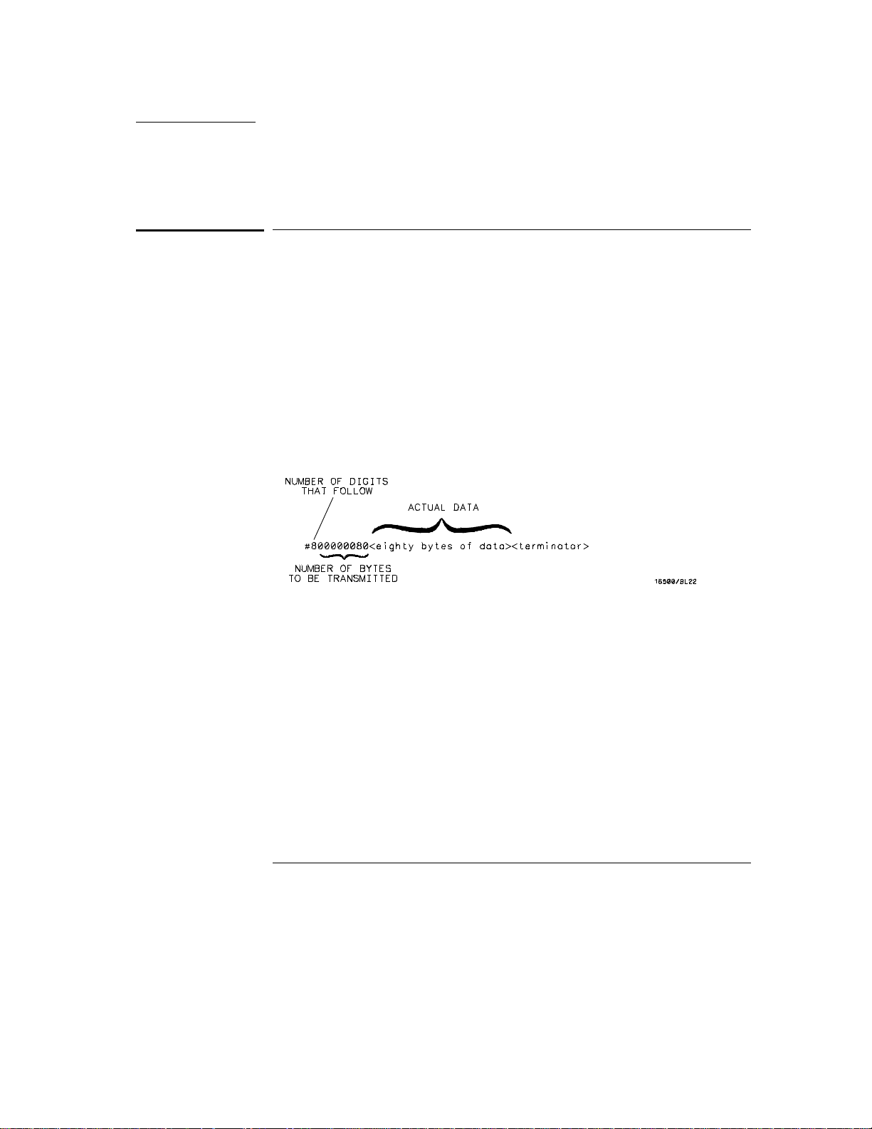
The syntax is a pound sign ( # ) followed by a non-zero digit representing the
number of digits in the decimal integer. Following the non zero digit is the
decimal integer that states the number of 8-bit data bytes to follow. This
number is followed by the actual data.
Indefinite-length block data is not supported on the HP1660C/CS-series.
For example, for transmitting 80 bytes of data, the syntax would be:
Figure 1-2
Definite-length Block Response Data
The "8" states the number of digits that follow, and "00000080" states the
number of bytes to be transmitted, which is 80.
1–20
Page 31

Introduction to Programming the HP 1660C/CS/CP
Multiple Queries
Multiple Queries
You can send multiple queries to the logic analyzer within a single program
message, but you must also read them back within a single program message.
This can be accomplished by either reading them back into a string variable
or into multiple numeric variables.
Example You can read the result of the query :SYSTEM:HEADER?;LONGFORM? into
the string variable Results$ with the command:
ENTER XXX; Results$
When you read the result of multiple queries into string variables, each
response is separated by a semicolon.
Example The response of the query :SYSTEM:HEADER?:LONGFORM? with HEADER
and LONGFORM turned on is:
:SYSTEM:HEADER 1;:SYSTEM:LONGFORM 1
If you do not need to see the headers when the numeric values are returned,
then you could use numeric variables. When you are receiving numeric data
into numeric variables, the headers should be turned off. Otherwise the
headers may cause misinterpretation of returned data.
Example The following program message is used to read the query
:SYSTEM:HEADERS?;LONGFORM? into multiple numeric variables:
ENTER XXX; Result1, Result2
1–21
Page 32

Introduction to Programming the HP 1660C/CS/CP
Instrument Status
Instrument Status
Status registers track the current status of the logic analyzer. By checking
the instrument status, you can find out whether an operation has been
completed, whether the instrument is receiving triggers, and more.
Chapter 6, "Status Reporting," explains how to check the status of the
instrument.
1–22
Page 33

2
Programming Over HP-IB
Page 34

Introduction
This section describes the interface functions and some general
concepts of the HP-IB. In general, these functions are defined by
IEEE 488.1 (HP-IB bus standard). They deal with general bus
management issues, as well as messages which can be sent over the
bus as bus commands.
2–2
Page 35

Programming Over HP-IB
Interface Capabilities
Interface Capabilities
The interface capabilities of the HP 1660C/CS/CP-series, as defined by IEEE
488.1 are SH1, AH1, T5, TE0, L3, LE0, SR1, RL1, PP0, DC1, DT1, C0, and E2.
Command and Data Concepts
The HP-IB has two modes of operation: command mode and data mode. The
bus is in command mode when the ATN line is true. The command mode is
used to send talk and listen addresses and various bus commands, such as a
group execute trigger (GET). The bus is in the data mode when the ATN line
is false. The data mode is used to convey device-dependent messages across
the bus. These device-dependent messages include all of the instrument
commands and responses found in chapters 8 through 36 of this manual.
Addressing
By attaching the logic analyzer printers or controller to the HP-IB port, you
automatically place the HP-IB interface into "talk-only" or "talk/listen" mode.
Talk-only mode must be used when you want the logic analyzer to talk
directly to a printer without the aid of a controller. Addressed talk/listen
mode is used when the logic analyzer will operate in conjunction with a
controller. When the logic analyzer is in the addressed talk/listen mode, the
following is true:
Each device on the HP-IB resides at a particular address ranging from 0 to
•
30.
The active controller specifies which devices will talk and which will listen.
•
An instrument may be talk-addressed, listen-addressed, or unaddressed by
•
the controller.
2–3
Page 36

Programming Over HP-IB
Communicating Over the HP-IB Bus (HP 9000 Series 200/300 Co ntroller)
If the controller addresses the instrument to talk, it will remain configured to
talk until it receives:
an interface clear message (IFC)
•
another instrument’s talk address (OTA)
•
its own listen address (MLA)
•
a universal untalk (UNT) command.
•
If the controller addresses the instrument to listen, it will remain configured
to listen until it receives:
an interface clear message (IFC)
•
its own talk address (MTA)
•
a universal unlisten (UNL) command.
•
Communicating Over the HP-IB Bus (HP 9000 Series
200/300 Controller)
Because HP-IB can address multiple devices through the same interface card,
the device address passed with the program message must include not only
the correct instrument address, but also the correct interface code.
Interface Select Code (Selects the Interface)
Each interface card has its own interface select code. This code is used by
the controller to direct commands and communications to the proper
interface. The default is always "7" for HP-IB controllers.
Instrument Address (Selects the Instrument)
Each instrument on the HP-IB port must have a unique instrument address
between decimals 0 and 30. The device address passed with the program
message must include not only the correct instrument address, but also the
correct interface select code.
2–4
Page 37

Programming Over HP-IB
Local, Remote, and Local Lockout
Example For example, if the instrument address is 4 and the interface select code is 7,
the instruction will cause an action in the instrument at device address 704.
DEVICE ADDRESS = (Interface Select Code) X 100 + (Instrument
Address)
Local, Remote, and Local Lockout
The local, remote, and remote with local lockout modes may be used for
various degrees of front-panel control while a program is running. The logic
analyzer will accept and execute bus commands while in local mode, and the
front panel will also be entirely active. If the HP 1660C/CS/CP series is in
remote mode, the logic analyzer will go from remote to local with any
front-panel activity. In remote with local lockout mode, all controls (except
the power switch) are entirely locked out. Local control can only be restored
by the controller.
CAUTION
Cycling the power will restore local control, but this will also reset certain
HP-IB states. It also resets the logic analyzer to the power-on defaults and
purges any acquired data in the acquisition memory.
The instrument is placed in remote mode by setting the REN (Remote
Enable) bus control line true, and then addressing the instrument to listen.
The instrument can be placed in local lockout mode by sending the local
lockout (LLO) command (see SYSTem:LOCKout in chapter 9, "Instrument
Commands"). The instrument can be returned to local mode by either
setting the REN line false, or sending the instrument the go to local (GTL)
command.
2–5
Page 38

Programming Over HP-IB
Bus Commands
Bus Commands
The following commands are IEEE 488.1 bus commands (ATN true). IEEE
488.2 defines many of the actions which are taken when these commands are
received by the logic analyzer.
Device Clear
The device clear (DCL) or selected device clear (SDC) commands clear the
input and output buffers, reset the parser, clear any pending commands, and
clear the Request-OPC flag.
Group Execute Trigger (GET)
The group execute trigger command will cause the same action as the
START command for Group Run: the instrument will acquire data for the
active waveform and listing displays.
Interface Clear (IFC)
This command halts all bus activity. This includes unaddressing all listeners
and the talker, disabling serial poll on all devices, and returning control to the
system controller.
2–6
Page 39

3
Programming Over RS-232-C
Page 40

Introduction
This chapter describes the interface functions and some general
concepts of the RS-232-C. The RS-232-C interface on this instrument
is Hewlett-Packard’s implementation of EIA Recommended Standard
RS-232-C, "Interface Between Data Terminal Equipment and Data
Communications Equipment Employing Serial Binary Data
Interchange." With this interface, data is sent one bit at a time, and
characters are not synchronized with preceding or subsequent data
characters. Each character is sent as a complete entity without
relationship to other events.
3–2
Page 41

Programming Over RS-232-C
Interface Operation
Interface Operation
The HP 1660C/CS/CP-series can be programmed with a controller over
RS-232-C using either a minimum three-wire or extended hardwire interface.
The operation and exact connections for these interfaces are described in
more detail in the following sections. When you are programming an HP
1660C/CS/CP-series over RS-232-C with a controller, you are normally
operating directly between two DTE (Data Terminal Equipment) devices as
compared to operating between a DTE device and a DCE (Data
Communications Equipment) device.
When operating directly between two DTE devices, certain considerations
must be taken into account. For a three-wire operation, XON/XOFF must be
used to handle protocol between the devices. For extended hardwire
operation, protocol may be handled either with XON/XOFF or by
manipulating the CTS and RTS lines of the RS-232-C link. For both threewire and extended hardwire operation, the DCD and DSR inputs to the logic
analyzer must remain high for proper operation.
With extended hardwire operation, a high on the CTS input allows the logic
analyzer to send data, and a low disables the logic analyzer data transmission.
Likewise, a high on the RTS line allows the controller to send data, and a low
signals a request for the controller to disable data transmission. Because
three-wire operation has no control over the CTS input, internal pull-up
resistors in the logic analyzer assure that this line remains high for proper
three-wire operation.
RS-232-C Cables
Selecting a cable for the RS-232-C interface depends on your specific
application, and, whether you wish to use software or hardware handshake
protocol. The following paragraphs describe which lines of the HP
1660C/CS/CP-series Logic Analyzer are used to control the handshake
operation of the RS-232-C relative to the system. To locate the proper cable
for your application, refer to the reference manual for your computer or
controller. Your computer or controller manual should describe the exact
handshake protocol your controller can use to operate over the RS-232-C
bus. Also in this chapter you will find HP cable recommendations for
hardware handshake.
3–3
Page 42

Programming Over RS-232-C
Minimum Three-Wire Interface with Software Protocol
Minimum Three-Wire Interface with Software Protocol
With a three-wire interface, the software (as opposed to interface hardware)
controls the data flow between the logic analyzer and the controller. The
three-wire interface provides no hardware means to control data flow
between the controller and the logic analyzer. Therefore, XON/OFF protocol
is the only means to control this data flow. The three-wire interface provides
a much simpler connection between devices since you can ignore hardware
handshake requirements.
The communications software you are using in your computer/controller must
be capable of using XON/XOFF exclusively in order to use t hree-wire interface
cables. For example, some communications software packages can use
XON/XOFF but are also dependent on the CTS, and DSR lines being true to
communicate.
The logic analyzer uses the following connections on its RS-232-C interface
for three-wire communication:
Pin 7 SGND (Signal Ground)
•
Pin 2 TD (Transmit Data from logic analyzer)
•
Pin 3 RD (Receive Data into logic analyzer)
•
The TD (Transmit Data) line from the logic analyzer must connect to the RD
(Receive Data) line on the controller. Likewise, the RD line from the logic
analyzer must connect to the TD line on the controller. Internal pull-up
resistors in the logic analyzer assure the DCD, DSR, and CTS lines remain
high when you are using a three-wire interface.
Extended Interface with Hardware Handshake
With the extended interface, both the software and the hardware can control
the data flow between the logic analyzer and the controller. This allows you
to have more control of data flow between devices. The logic analyzer uses
the following connections on its RS-232-C interface for extended interface
communication:
3–4
Page 43

Programming Over RS-232-C
Extended Interface with Hardware Handshake
Pin 7 SGND (Signal Ground)
•
Pin 2 TD (Transmit Data from logic analyzer)
•
Pin 3 RD (Receive Data into logic analyzer)
•
The additional lines you use depends on your controller’s implementation of
the extended hardwire interface.
Pin 4 RTS (Request To Send) is an output from the logic analyzer which
•
can be used to control incoming data flow.
Pin 5 CTS (Clear To Send) is an input to the logic analyzer which
•
controls data flow from the logic analyzer.
Pin 6 DSR (Data Set Ready) is an input to the logic analyzer which
•
controls data flow from the logic analyzer within two bytes.
Pin 8 DCD (Data Carrier Detect) is an input to the logic analyzer which
•
controls data flow from the logic analyzer within two bytes.
Pin 20 DTR (Data Terminal Ready) is an output from the logic analyzer
•
which is enabled as long as the logic analyzer is turned on.
The TD (Transmit Data) line from the logic analyzer must connect to the RD
(Receive Data) line on the controller. Likewise, the RD line from the logic
analyzer must connect to the TD line on the controller.
The RTS (Request To Send), is an output from the logic analyzer which can
be used to control incoming data flow. A true on the RTS line allows the
controller to send data and a false signals a request for the controller to
disable data transmission.
The CTS (Clear To Send), DSR (Data Set Ready), and DCD (Data Carrier
Detect) lines are inputs to the logic analyzer, which control data flow from
the logic analyzer. Internal pull-up resistors in the logic analyzer assure the
DCD and DSR lines remain high when they are not connected. If DCD or
DSR are connected to the controller, the controller must keep these lines
along with the CTS line high to enable the logic analyzer to send data to the
controller. A low on any one of these lines will disable the logic analyzer data
transmission. Pulling the CTS line low during data transmission will stop
logic analyzer data transmission immediately. Pulling either the DSR or DCD
line low during data transmission will stop logic analyzer data transmission,
but as many as two additional bytes may be transmitted from the logic
analyzer.
3–5
Page 44
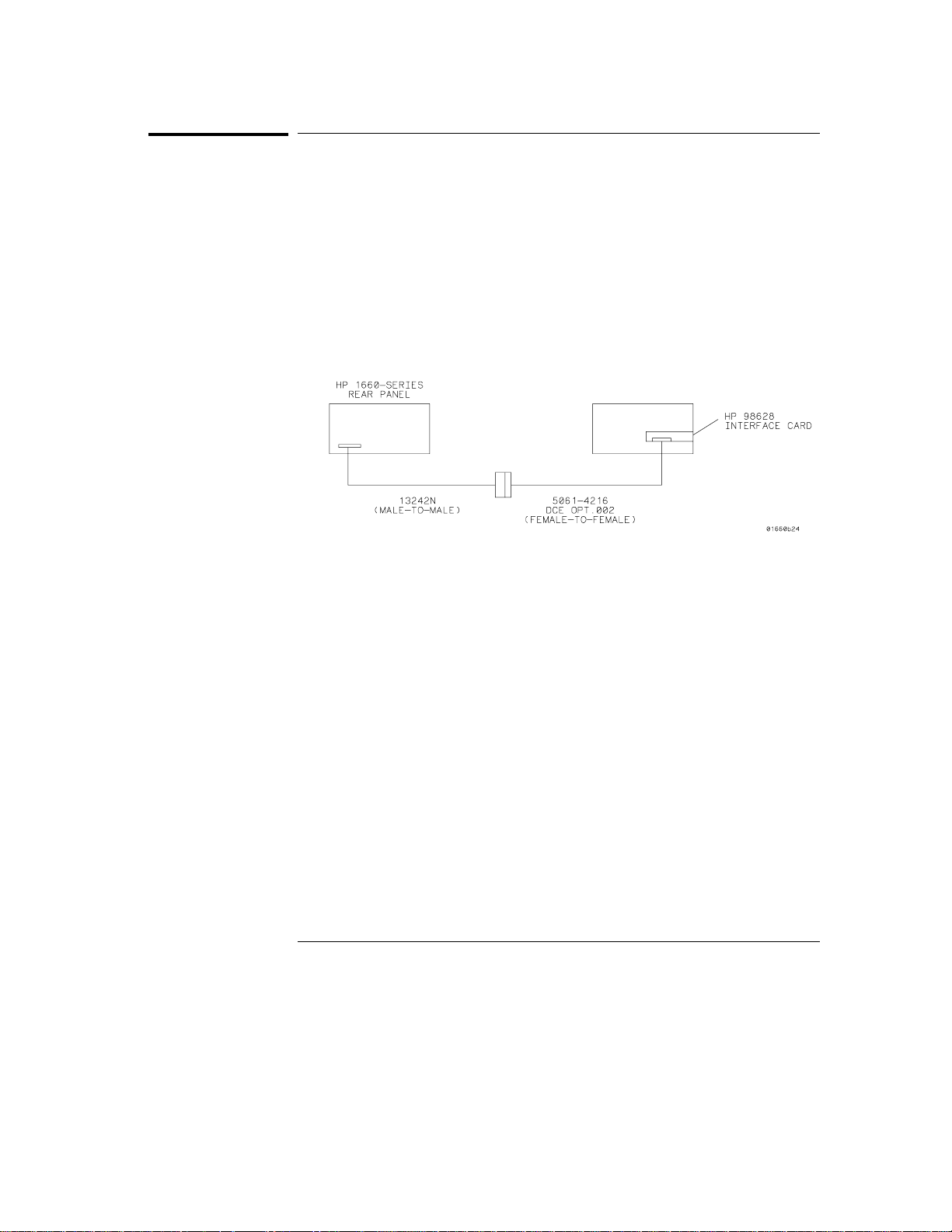
Figure 3-1
Programming Over RS-232-C
Cable Exampl es
Cable Examples
HP 9000 Series 300
Figure 3-1 is an example of how to connect the HP 1660C/CS/CP-series to the
HP 98628A Interface card of an HP 9000 series 300 controller. For more
information on cabling, refer to the reference manual for your specific
controller.
Because this example does not have the correct connections for hardware
handshake, you must use the XON/XOFF protocol when connecting the logic
analyzer.
Cable Example
HP Vectra Personal Computers and Compatibles
Figures 3-2 through 3-4 give examples of three cables that will work for the
extended interface with hardware handshake. Keep in mind that these
cables should work if your computer’s serial interface supports the four
common RS-232-C handshake signals as defined by the RS-232-C standard.
The four common handshake signals are Data Carrier Detect (DCD), Data
Terminal Ready (DTR), Clear to Send (CTS), and Ready to Send (RTS).
Figure 3-2 shows the schematic of a 25-pin female to 25-pin male cable. The
following HP cables support this configuration:
HP 17255D, DB-25(F) to DB-25(M), 1.2 meter
•
HP 17255F, DB-25(F) to DB-25(M), 1.2 meter, shielded.
•
In addition to the female-to-male cables with this configuration, a
male-to-male cable 1.2 meters in length is also available: HP 17255M,
DB-25(M) to DB-25(M), 1.2 meter
3–6
Page 45
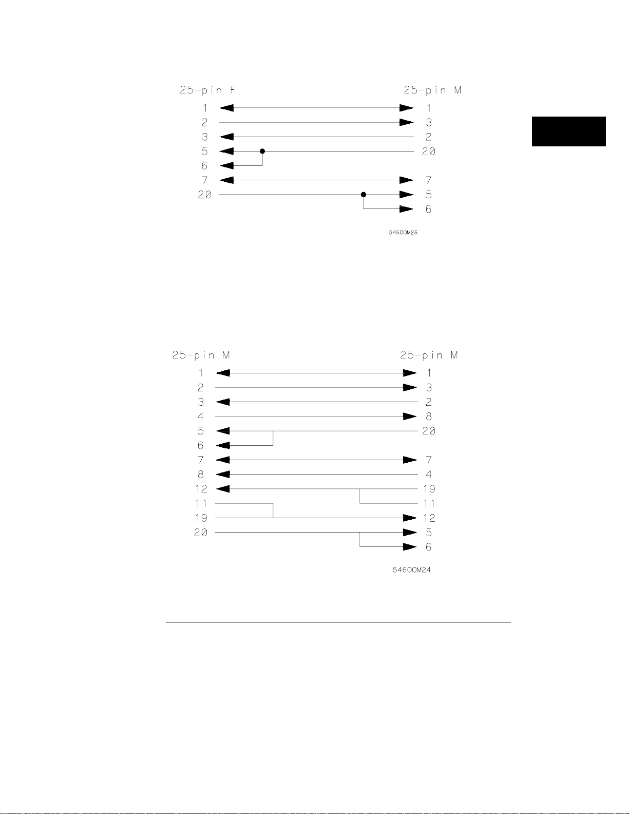
Figure 3-2
Programming Over RS-232-C
Cable Exampl es
25-pin (F) to 25-pin (M) Cable
Figure 3-3 shows the schematic of a 25-pin male to 25-pin male cable 5
meters in length. The following HP cable supports this configuration:
HP 13242G, DB-25(M) to DB-25(M), 5 meter
•
Figure 3-3
25-pin (M) to 25-pin (M) Cable
3–7
Page 46
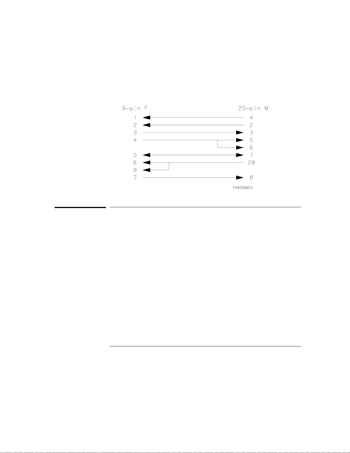
Figure 3-4
Programming Over RS-232-C
Configuring the Logic Analzer Interface
Figure 3-4 shows the schematic of a 9-pin female to 25-pin male cable. The
following HP cables support this configuration:
HP 24542G, DB-9(F) to DB-25(M), 3 meter
•
HP 24542H, DB-9(F) to DB-25(M), 3 meter, shielded
•
HP 45911-60009, DB-9(F) to DB-25(M), 1.5 meter
•
9-pin (F) to 25-pin (M) Cable
Configuring the Logic Analzer Interface
The RS-232-C menu field in the System External I/O Menu allows you access
to the RS-232-C External I/O menu where the RS-232-C interface is
configured. If you are not familiar with how to configure the RS-232-C
interface, refer to the logic analyzer’s User’s Guide.
3–8
Page 47

Programming Over RS-232-C
Interface Capabilities
Interface Capabilities
The baud rate, stopbits, parity, protocol, and databits must be configured
exactly the same for both the controller and the logic analyzer to properly
communicate over the RS-232-C bus. The RS-232-C interface capabilities of
the HP 1660C/CS/CP-series are listed below:
Baud Rate: 110, 300, 600, 1200, 2400, 4800, 9600, or 19.2k
•
Stop Bits: 1, 1.5, or 2
•
Parity: None, Odd, or Even
•
Protocol: None or Xon/Xoff
•
Data Bits: 8
•
Protocol
NONE With a three-wire interface, selecting NONE for the protocol
does not allow the sending or receiving device to control data flow. No
control over the data flow increases the possibility of missing data or
transferring incomplete data.
With an extended hardwire interface, selecting NONE allows a hardware
handshake to occur. With hardware handshake, the hardware signals control
dataflow.
Xon/Xoff Xon/Xoff stands for Transmit On/Transmit Off. With this
mode, the receiver (controller or logic analyzer) controls data flow, and,
can request that the sender (logic analyzer or controller) stop data flow.
By sending XOFF (ASCII 19) over its transmit data line, the receiver
requests that the sender disables data transmission. A subsequent XON
(ASCII 17) allows the sending device to resume data transmission.
Data Bits
Data bits are the number of bits sent and received per character that
represent the binary code of that character. Characters consist of either 7 or
8 bits, depending on the application. The HP 1660C/CS/CP-series supports
8-bit only.
8-Bit Mode Information is usually stored in bytes (8 bits at a time).
With 8-bit mode, you can send and receive data just as it is stored,
without the need to convert the data.
3–9
Page 48

Programming Over RS-232-C
RS-232-C Bus Addressing
The controller and the HP 1660C/CS/CP-series must be in the same bit mode
to properly communicate over the RS-232-C. This means that the controller
must have the capability to send and receive 8-bit data.
See Also For more information on the RS-232-C interface, refer to the logic analyzer’s
User’s Guide. For information on RS-232-C voltage levels and connector
pinouts, refer to the logic analyzer’s Service Guide.
RS-232-C Bus Addressing
The RS-232-C address you must use depends on the computer or controller
you are using to communicate with the logic analyzer.
HP Vectra Personal Computers or compatibles
If you are using an HP Vectra Personal Computer or compatible, it must have
an unused serial port to which you connect the logic analyzer’s RS-232-C
port. The proper address for the serial port is dependent on the hardware
configuration of your computer. Additionally, your communications software
must be configured to address the proper serial port. Refer to your computer
and communications software manuals for more information on setting up
your serial port address.
HP 9000 Series 300 Controllers
Each RS-232-C interface card for the HP 9000 Series 300 Controller has its
own interface select code. This code is used by the controller for directing
commands and communications to the proper interface by specifying the
correct interface code for the device address.
Generally, the interface select code can be any decimal value between 0 and
31, except for those interface codes which are reserved by the controller for
internal peripherals and other internal interfaces. This value can be selected
through switches on the interface card. For example, if your RS-232-C
interface select code is 9, the device address required to communicate over
the RS-232-C bus is 9. For more information, refer to the reference manual
for your interface card or controller.
3–10
Page 49

Programming Over RS-232-C
Lockout Command
Lockout Command
To lockout the front-panel controls, use the Mainframe command LOCKout.
When this function is on, all controls (except the power switch) are entirely
locked out. Local control can only be restored by sending the :LOCKout
OFF command.
CAUTION
See Also For more information on this command see chapter 9, "Instrument
Cycling the power will also restore local control, but this will also reset
certain RS-232-C states. It also resets the logic analyzer to the power-on
defaults and purges any acquired data in the acquisition memory of all the
installed modules.
Commands."
3–11
Page 50

3–12
Page 51

4
Programming and Documentation Conventions
Page 52

Introduction
This chapter covers the programming conventions used in
programming the instrument, as well as the documentation
conventions used in this manual. This chapter also contains a detailed
description of the command tree and command tree traversal.
4–2
Page 53

Programming and Documentation Conventions
Truncation Rule
Truncation Rule
The truncation rule for the keywords used in headers and parameters is:
If the long form has four or fewer characters, there is no change in the
•
short form. When the longform has more than four characters the short
form is just the first four characters, unless the fourth character is a
vowel. In that case only the first three characters are used.
There are some commands that do not conform to the truncation rule by design.
These will be not ed in their respective description pages.
Some examples of how the truncation rule is applied to various commands
are shown in table 4-1.
Table 4-1
Truncation Examples
Long Form Short Form
OFF OFF
DATA DATA
START STAR
LONGFORM LONG
DELAY DEL
ACCUMULATE ACC
4–3
Page 54

Programming and Documentation Conventions
Infinity Representation
Infinity Representation
The representation of infinity is 9.9E+37 for real numbers and 32767 for
integers. This is also the value returned when a measurement cannot be
made.
Sequential and Overlapped Commands
IEEE 488.2 makes the distinction between sequential and overlapped
commands. Sequential commands finish their task before the execution of
the next command starts. Overlapped commands run concurrently; therefore,
the command following an overlapped command may be started before the
overlapped command is completed. The overlapped commands for the
HP 1660C/CS/CP-series are STARt and STOP.
Response Generation
IEEE 488.2 defines two times at which query responses may be buffered.
The first is when the query is parsed by the instrument and the second is
when the controller addresses the instrument to talk so that it may read the
response. The HP 1660C/CS/CP-series will buffer responses to a query when
it is parsed.
Syntax Diagrams
At the beginning of each chapter in Parts 2 through 4, "Commands," is a
syntax diagram showing the proper syntax for each command. All characters
contained in a circle or oblong are literals, and must be entered exactly as
shown. Words and phrases contained in rectangles are names of items used
with the command and are described in the accompanying text of each
command. Each line can only be entered from one direction as indicated by
the arrow on the entry line. Any combination of commands and arguments
that can be generated by following the lines in the proper direction is
syntactically correct. An argument is optional if there is a path around it.
When there is a rectangle which contains the word "space," a white space
character must be entered. White space is optional in many other places.
4–4
Page 55

Programming and Documentation Conventions
Notation Conventions and Definitions
Notation Conventions and Definitions
The following conventions are used in this manual when describing
programming rules and example.
< > Angular brackets enclose words or characters that are used to symbolize a
program code parameter or a bus command
::= "is defined as." For example, A ::= B indicates that A can be replaced by B in
any statement containing A.
| "or." Indicates a choice of one element from a list. For example, A | B
indicates A or B, but not both.
... An ellipsis (trailing dots) is used to indicate that the preceding element may
be repeated one or more times.
[ ] Square brackets indicate that the enclosed items are optional.
{ } When several items are enclosed by braces and separated by vertical bars (|),
one, and only one of these elements must be selected.
XXX Three Xs after an ENTER or OUTPUT statement represent the device
address required by your controller.
<NL> Linefeed (ASCII decimal 10).
The Command Tree
The command tree (figure 4-1) shows all commands in the HP
1660C/CS/CP-series logic analyzers and the relationship of the commands to
each other. Parameters are not shown in this figure. The command tree
allows you to see what the HP 1660C/CS/CP-series’ parser expects to receive.
All legal headers can be created by traversing down the tree, adding
keywords until the end of a branch has been reached.
4–5
Page 56

Programming and Documentation Conventions
Tree Travers al Rules
Command Types
As shown in chapter 1, "Header Types," there are three types of headers.
Each header has a corresponding command type. This section shows how
they relate to the command tree.
System Commands The system commands reside at the top level of
the command tree. These commands are always parsable if they occur at
the beginning of a program message, or are preceded by a colon. START
and STOP are examples of system commands.
Subsystem Commands Subsystem commands are grouped together
under a common node of the tree, such as the MMEMORY commands.
Common Commands Common commands are independent of the tree,
and do not affect the position of the parser within the tree. *CLS and
*RST are examples of common commands.
Tree Traversal Rules
Command headers are created by traversing down the command tree. For
each group of keywords not separated by a branch, one keyword must be
selected. As shown on the tree, branches are always preceded by colons. Do
not add spaces around the colons. The following two rules apply to traversing
the tree:
A leading colon (the first character of a header) or a <terminator> places the
parser at the root of the command tree.
Executing a subsystem command places you in that subsystem until a leading
colon or a <terminator> is found. The parser will stay at the colon above the
keyword where the last header terminated. Any command below that point
can be sent within the current program message without sending the
keywords(s) which appear above them.
4–6
Page 57

Programming and Documentation Conventions
Tree Traversal Rules
The following examples are written using HP BASIC 6.2 on a HP 9000 Series
200/300 Controller. The quoted string is placed on the bus, followed by a
carriage return and linefeed (CRLF). The three Xs (XXX) shown in this
manual after an ENTER or OUTPUT statement represents the device address
required by your controller.
Example 1 In this example, the colon between SYSTEM and HEADER is necessary since
SYSTEM:HEADER is a compound command. The semicolon between the
HEADER command and the LONGFORM command is the required <program
message unit separator> . The LONGFORM command does not need
SYSTEM preceding it, since the SYSTEM:HEADER command sets the parser
to the SYSTEM node in the tree.
OUTPUT XXX;":SYSTEM:HEADER ON;LON GFORM ON"
Example 2 In the first line of this example, the subsystem selector is implied for the
STORE command in the compound command. The STORE command must
be in the same program message as the INITIALIZE command, since the
<program message terminator> will place the parser back at the root
of the command tree.
A second way to send these commands is by placing MMEMORY: before the
STORE command as shown in the fourth line of this example 2.
OUTPUT XXX;":MMEMORY:INITIALIZE;STORE ’FILE ’,’FILE
DESCRIPTION’"
or
OUTPUT XXX;":MMEMORY:INITIALIZE "
OUTPUT XXX;":MMEMORY:STORE ’FILE ’,’FILE DESCRIPTION’"
Example 3 In this example, the leading colon before SYSTEM tells the parser to go back
to the root of the command tree. The parser can then see the
SYSTEM:PRINT command.
OUTPUT XXX;":MMEM:CATALOG?;:SYS TEM:PRINT ALL"
4–7
Page 58
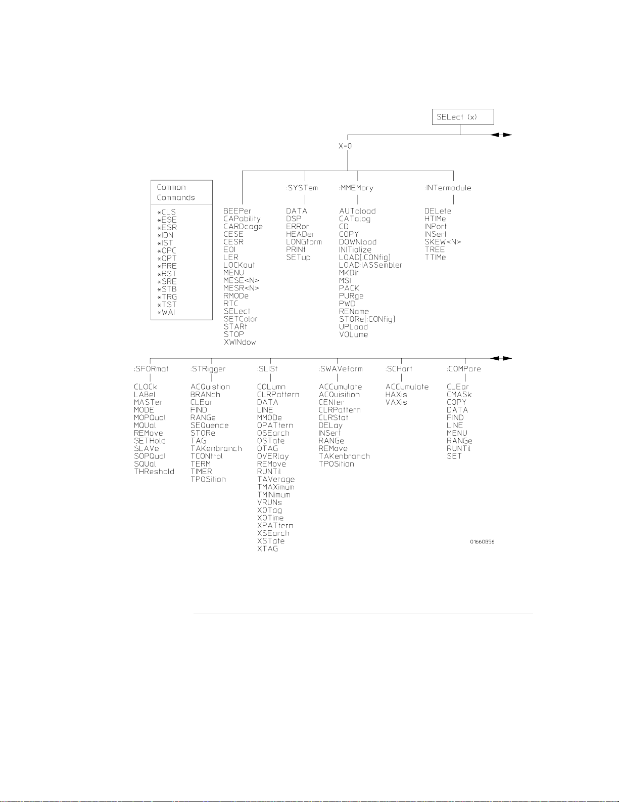
Figure 4-1
Programming and Documentation Conventions
Tree Travers al Rules
HP 1660C/CS/CP-series Command Tree
4–8
Page 59
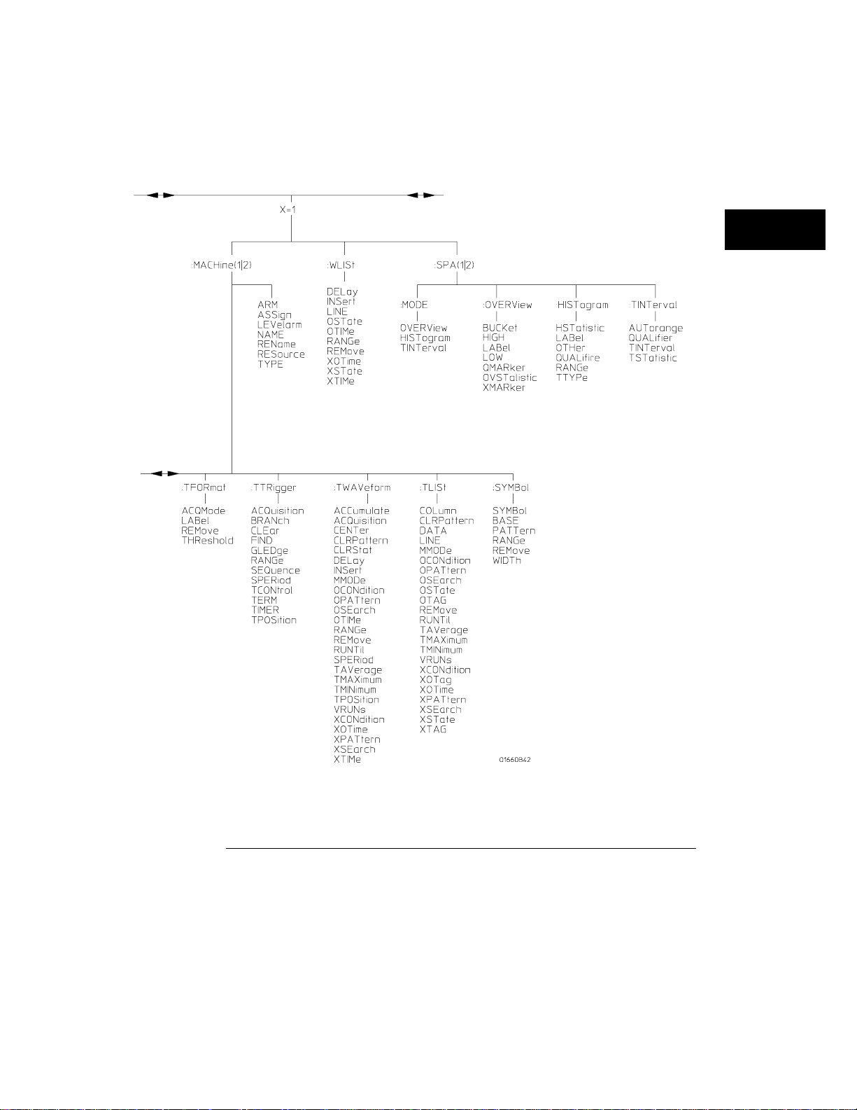
Figure 4-1 (continued)
Programming and Documentation Conventions
Tree Traversal Rules
HP 1660C/CS /CP-series Command Tree (continued)
4–9
Page 60
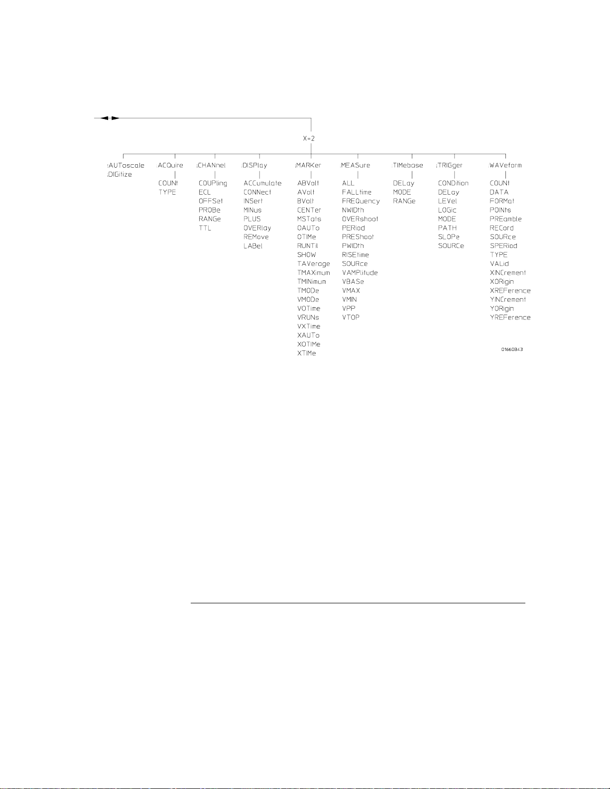
Figure 4-1 (continued)
Programming and Documentation Conventions
Tree Travers al Rules
HP 1660C/CS /CP-series Command Tree (continued)
4–10
Page 61

Table 4-2
Alphabetic Command Cross-Reference
Programming and Documentation Conventions
Tree Traversal Rules
Command Subsystem
ABVOLt MARKer
ACCumulate SCHart, SWAVeform, TWAVeform,
DISPlay
ACQMode TFORmat
ACQuisition STRigger, SWAVeform, TTRigger,
TWAVeform
ALL MEASure
ARM MACHine
ASSign MACHine
AUToload MMEMory
AUTorange TINTerval
AUToscale MODULE LEVEL
AVOLt MARKer
BASE SYMBol
BEEPer Instrument
BRANch STRigger, TTRigger
BUCKet OVERView
BVOLt MARKer
CAPability Instrument
CARDcage Instrument
CATalog MMEMory
CD MMEMory
CENTer SWAVeform, TWAVeform, MARKer
CESE Instrument
CESR Instrument
CLEar COMPare, STRigger, TTRigger
CLOCk SFORmat
CLRPattern SLISt, SWAVeform, TLISt, TWAVeform
CLRStat SWAVeform, TWAVeform
CMASk COMPare
COLumn SLISt, TLISt
CONDition TRIGger
CONNect DISPlay
COPY COMPare, MMEMory
COUNt ACQuire, WAVeforml
COUPling CHANNel
DATA COMPare, SLISt, SYSTem, TLISt,
WAVeform
DELay SWAVeform, TWAVeform, WLISt,
TIMebase. TRI Gger
Command Subsystem
DELete INTermodule
DIGitize ROOT
DOWNload MMEMory
DSP SYSTem
ECL CHANnel
EOI Instrument
ERRor SYSTem
FALLtime MEASure
FIND COMPare, STRigger, TTRigger
FORMat WAVeform
FREQuency MEASure
GLEDge TTRigger
HAXis SCHart
HEADer SYSTem
HIGH OVERView
HISTogram SPA, MODE
HSTatistic HISTogram
HTIMe INTermodule
INITialize MMEMory
INPort INTermodule
INSert INTermodule, SWAVeform, TWAVeform,
WLISt, DISPlay
LABel SFORmat , TFORmat, DISPlay, OVE RView,
HISTogram
LER Instrument
LEVel TRIGger
LEVelarm MACHine
LINE COMPare, SLISt, TLISt, WLISt
LOAD MMEMory
LOCKout Instrument
LOGic TRIGger
LONGform SYSTem
LOW OVERView
MACHine Instrument
MASTer SFORmat
MENU COMPare, Instrument
MESE I nstrument
MESR Instrument
MINus DISPlay
4–11
Page 62

Programming and Documentation Conventions
Tree Travers al Rules
Table 4-2 (continued)
Alphabetic Command Cross-Reference (continued)
Command Subs ystem
MKDir MMEMory
MMEMory Instrument
MMODe SLISt, TLISt, TWAVeform
MODE SFORmat, TIMebase, TRIGger, SPA
MOPQual SFORmat
MQUal SFORmat
MSI MMEMory
MSTats MARKer
NAME MACHine
NWIDth M EASure
OAUTo MARKer
OCONdition TLISt, TWAVef or m
OFFSet CHANnel
OMARker OVERView
OPATtern SLISt, TLISt, TWAVeform
OSEarch SLISt, TLISt, TWAVeform
OSTate SLISt, TLISt, WLISt
OTAG SLISt, TLISt
OTHer HISTogram
OTIMe TWAVeform, WLISt, MARKer
OVERlay SLISt, DISPlay
OVERshoot MEASure
OVERView SPA
OVSTatistic OVERView
PACK MMEMory
PATH TRIGger
PATTern SYMBol
PERiod MEASure
PLUS DISPlay
POINts WAVeform
PREamble WAVeform
PREShoot MEASure
PRINt SYSTem
PROBe CHANnel
PURGe MMEMory
PWD MMEMory
PWIDth MEASure
QUALifier HISTogram, TI NTerval
Command Subsystem
RANGe COM Pare, STRigger, SWAVefo rm,
SYMBol, TTRigger, TWAVe form, WLISt,
CHANnel, TIMebase, HISTogram
RECord WAVeform
REMove SFORmat, SLISt, SWAVeform, SYMBol,
TFORmat, TLISt, TWAVeform, DISPlay
REName MACHine, MMEMory
RESource MACHine
RISetime MEASure
RMODe Instrument
RTC Instrument
RUNTil COMPare, SLISt, TLISt, TWAVeform,
MARKer
SELect Instrument
SEQuence STRigger, TTRigger
SET COMPare
SETColor Instrument
SETHold SFORmat
SETup SYSTem
SHOW MARKer
SKEW INTermodule
SLAVe SFORmat
SLOPe TRIGger
SOPQual SFORmat
SOURce MEASure, TRIGger, WAVeform
SPA Instrument
SPERiod TTRIGger, TWAVeform, WAVeform
SQUal SFORmat
STARt Instrument
STOP Instrument
STORe MMEMory, STRigger
TAG STRigger
TAKenbranc STRigger, SWAVeform
TAVerage SLI St, TLISt, TWAVeform, MARKer
TCONtrol STRigger, TTRigger
TERM STRigger, TTRigger
THReshold SFORmat, TFORmat
TIMER STRigger, TTRigger
TINTerval SPA, MODE, TINTerval
4–12
Page 63

Table 4-2 (continued)
Alphabetic Command Cross-Reference (continued)
Programming and Documentation Conventions
Tree Traversal Rules
Command Subsystem
TMAXimum SLISt, TLISt, TWAVeform, MARKer
TMINimum SL ISt, TLISt, TWAVeform, MARKer
TMODe MA RKer
TPOSition STRigger, SWAVeform , TTRigger,
TWAVeform
TREE INTermodule
TSTatistic TINTerval
TTIMe INTermodule
TTL CHANnel
TTYPe HISTogram
TYPE MACHine
UPLoad MMEMory
VALid WAVeform
VAMPlitude MEASure
VAXis SCHart
VBAse MEASure
VMAX MEASure
VMIN MEASure
VMODe MARKer
VOLume MMEMory
VOTime MARKer
VPP MEASure
VRUNs SLISt, TLISt, TWAVeform, MARKer
VTOP MEASure
Command Subsystem
VXTime MARKer
WIDTh SYMBol
WLISt Instrument
XAUTo MARKer
XCONdition TLISt, TWAVeform
XINCrment WAVeform
XMARker OVERView
XORigin WAVeform
XOTag SLISt, TLISt
XOTime SLISt, TLISt, TWAVeform, WLISt,
MARKer
XPATtern SLISt, TLISt, TWAVeform
XREFrence WAVeform
XSEarch SLISt, TLISt, TWAVeform
XSTate SLISt, TLISt, WLISt
XTAG SLISt, TLISt
XTIMe T WAVeform, WLISt, M ARKer
YINCreme nt WAVeform
YORigin WAVeform
YREFerence WAVeform
XWINdow Instrument
4–13
Page 64

Programming and Documentation Conventions
Command Set Organization
Command Set Organization
The command set for the HP 1660C/CS/CP-series logic analyzers is divided
into 28 separate groups: common commands, instrument commands, system
commands and 25 sets of subsystem commands. Each of the 28 groups of
commands is described in a separate chapter in Parts 2 through 4,
"Commands." Each of the chapters contain a brief description of the
subsystem, a set of syntax diagrams for those commands, and finally, the
commands for that subsystem in alphabetical order. The commands are
shown in the long form and short form using upper and lowercase letters. As
an example AUToload indicates that the long form of the command is
AUTOLOAD and the short form of the command is AUT. Each of the
commands contain a description of the command, its arguments, and the
command syntax.
Subsystems
There are 25 subsystems in this instrument. In the command tree (figure
4-1) they are shown as branches, with the node above showing the name of
the subsystem. Only one subsystem may be selected at a time. At power on,
the command parser is set to the root of the command tree; therefore, no
subsystem is selected. The 25 subsystems in the HP 1660C/CS/CP-series logic
analyzers are:
SYSTem - controls some basic functions of the instrument.
•
MMEMory - provides access to the internal disk drive.
•
INTermodule - provides access to the Intermodule bus (IMB).
•
MACHine - provides access to analyzer functions and subsystems.
•
WLISt - allows access to the mixed (timing/state) functions.
•
SFORmat - allows access to the state format functions.
•
STRigger - allows access to the state trigger functions.
•
SLISt - allows access to the state listing functions.
•
SWAVeform - allows access to the state waveforms functions.
•
SCHart - allows access to the state chart functions.
•
COMPare - allows access to the compare functions.
•
4–14
Page 65

Programming and Documentation Conventions
Program Examples
TFORmat - allows access to the timing format functions.
•
TTRigger - allows access to the timing trigger functions.
•
TWAVeform - allows access to the timing waveforms functions.
•
TLISt - allows access to the timing listing functions.
•
SYMBol - allows access to the symbol specification functions.
•
ACQuire - sets up acquisition conditions for the digitize function.
•
CHANnel - controls the oscilloscope channel display and vertical axis.
•
DISPlay - allows data to be displayed.
•
MARKer - allows access to the oscilloscope’s time and voltage markers.
•
MEASure - allows automatic parametric measurements.
•
TIMebase - controls the oscilloscope timebase and horizontal axis.
•
TRIGger - allows access to the oscilloscope’s trigger functions.
•
SPA - provides access to software profiling functions and subsystems.
•
WAVeform - used to transfer waveform data from the oscilloscope to a
•
controller.
Program Examples
The program examples in the following chapters and chapter 43,
"Programming Examples," were written on an HP 9000 Series 200/300
controller using the HP BASIC 6.2 language. The programs always assume a
generic address for the HP 1660C/CS/CP-series logic analyzers of XXX.
In the examples, you should pay special attention to the ways in which the
command and/or query can be sent. Keywords can be sent using either the
long form or short form (if one exists for that word). With the exception of
some string parameters, the parser is not case-sensitive. Uppercase and
lowercase letters may be mixed freely. System commands like HEADer and
LONGform allow you to dictate what forms the responses take, but they have
no affect on how you must structure your commands and queries.
4–15
Page 66

Programming and Documentation Conventions
Program Examples
Example The following commands all set the Timing Waveform Delay to 100 ms.
Keywords in long form, numbers using the decimal format.
OUTPUT XXX;":MACHINE1:TWAVEFORM:DELAY .1"
Keywords in short form, numbers using an exponential format.
OUTPUT XXX;":MACH1:TWAV:DEL 1E-1"
Keywords in short form using lowercase letters, numbers using a suffix.
OUTPUT XXX;":mach1:twav:del 100ms"
In these examples, the colon shown as the first character of the command is
optional on the HP 1660C/CS/CP-series. The space between DELay and the
argument is required.
4–16
Page 67

5
Message Communication and System Functions
Page 68

Introduction
This chapter describes the operation of instruments that operate in
compliance with the IEEE 488.2 (syntax) standard. It is intended to
give you enough basic information about the IEEE 488.2 Standard to
successfully program the logic analyzer. You can find additional
detailed information about the IEEE 488.2 Standard in ANSI/IEEE Std
488.2-1987, "IEEE Standard Codes, Formats, Protocols, and Common
Commands."
The HP 1660C/CS/CP-series is designed to be compatible with other
Hewlett-Packard IEEE 488.2 compatible instruments. Instruments
that are compatible with IEEE 488.2 must also be compatible with
IEEE 488.1 (HP-IB bus standard); however, IEEE 488.1 compatible
instruments may or may not conform to the IEEE 488.2 standard.
The IEEE 488.2 standard defines the message exchange protocols by
which the instrument and the controller will communicate. It also
defines some common capabilities, which are found in all IEEE 488.2
instruments. This chapter also contains a few items which are not
specifically defined by IEEE 488.2, but deal with message
communication or system functions.
The syntax and protocol for RS-232-C program messages and
response messages for the HP 1660C/CS/CP-series are structured very
similar to those described by 488.2. In most cases, the same structure
shown in this chapter for 488.2 will also work for RS-232-C. Because
of this, no additional information has been included for RS-232-C.
5–2
Page 69

Message Commu nication and System Functio ns
Protocols
Protocols
The protocols of IEEE 488.2 define the overall scheme used by the controller
and the instrument to communicate. This includes defining when it is
appropriate for devices to talk or listen, and what happens when the protocol
is not followed.
Functional Elements
Before proceeding with the description of the protocol, a few system
components should be understood.
Input Buffer The input buffer of the instrument is the memory area
where commands and queries are stored prior to being parsed and
executed. It allows a controller to send a string of commands to the
instrument which could take some time to execute, and then proceed to
talk to another instrument while the first instrument is parsing and
executing commands.
Output Queue The output queue of the instrument is the memory area
where all output data (<response messages>) are stored until read by
the controller.
Parser The instrument’s parser is the component that interprets the
commands sent to the instrument and decides what actions should be
taken. "Parsing" refers to the action taken by the parser to achieve this
goal. Parsing and executing of commands begins when either the
instrument recognizes a <program message terminator> (defined later in
this chapter) or the input buffer becomes full. If you wish to send a long
sequence of commands to be executed and then talk to another
instrument while they are executing, you should send all the commands
before sending the <program message terminator>.
5–3
Page 70

Message Commun ication and System Functions
Protocols
Protocol Overview
The instrument and controller communicate using <program message>s and
<response message>s. These messages serve as the containers into which
sets of program commands or instrument responses are placed. <program
message>s are sent by the controller to the instrument, and <response
message>s are sent from the instrument to the controller in response to a
query message. A <query message> is defined as being a <program
message> which contains one or more queries. The instrument will only talk
when it has received a valid query message, and therefore has something to
say. The controller should only attempt to read a response after sending a
complete query message, but before sending another <program message>.
The basic rule to remember is that the instrument will only talk when
prompted to, and it then expects to talk before being told to do something
else.
Protocol Operation
When the instrument is turned on, the input buffer and output queue are
cleared, and the parser is reset to the root level of the command tree.
The instrument and the controller communicate by exchanging complete
<program message>s and <response message>s. This means that the
controller should always terminate a <program message> before attempting
to read a response. The instrument will terminate <response message>s
except during a hardcopy output.
If a query message is sent, the next message passing over the bus should be
the <response message>. The controller should always read the complete
<response message> associated with a query message before sending another
<program message> to the same instrument.
The instrument allows the controller to send multiple queries in one query
message. This is referred to as sending a "compound query." As will be
noted later in this chapter, multiple queries in a query message are separated
by semicolons. The responses to each of the queries in a compound query
will also be separated by semicolons.
Commands are executed in the order they are received.
5–4
Page 71

Message Commu nication and System Functio ns
Syntax Diagrams
Protocol Exceptions
If an error occurs during the information exchange, the exchange may not be
completed in a normal manner. Some of the protocol exceptions are shown
below.
Command Error A command error will be reported if the instrument
detects a syntax error or an unrecognized command header.
Execution Error An execution error will be reported if a parameter is
found to be out of range, or if the current settings do not allow execution
of a requested command or query.
Device-specific Error A device-specific error will be reported if the
instrument is unable to execute a command for a strictly device
dependent reason.
Query Error A query error will be reported if the proper protocol for
reading a query is not followed. This includes the interrupted and
unterminated conditions described in the following paragraphs.
Syntax Diagrams
The example syntax diagram is in this chapter are similar to the syntax
diagrams in the IEEE 488.2 specification. Commands and queries are sent to
the instrument as a sequence of data bytes. The allowable byte sequence for
each functional element is defined by the syntax diagram that is shown.
The allowable byte sequence can be determined by following a path in the
syntax diagram. The proper path through the syntax diagram is any path
that follows the direction of the arrows. If there is a path around an element,
that element is optional. If there is a path from right to left around one or
more elements, that element or those elements may be repeated as many
times as desired.
5–5
Page 72
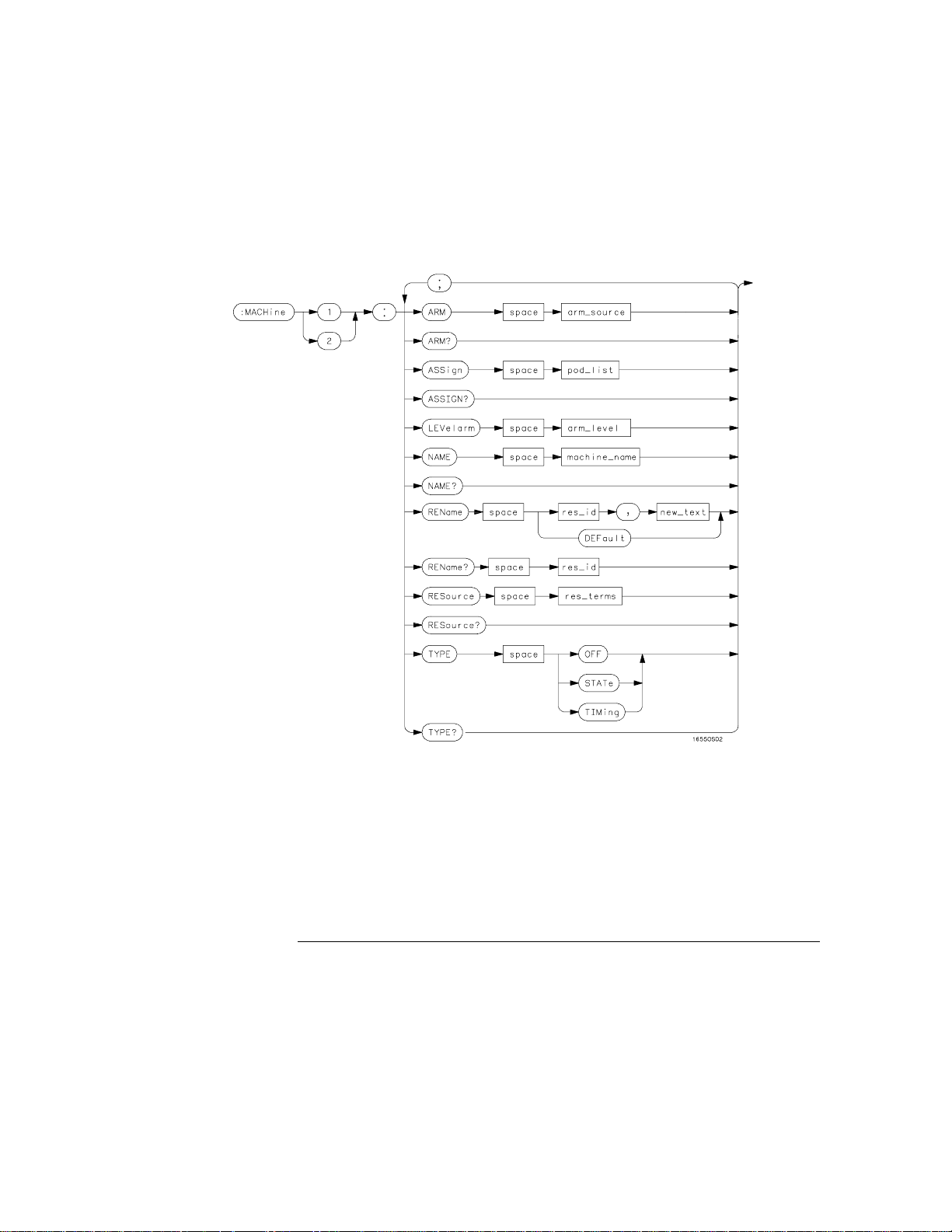
Figure 5-1
Message Commun ication and System Functions
Syntax Diagrams
Example syntax diagram
5–6
Page 73

Message Commu nication and System Functio ns
Syntax Overview
Syntax Overview
This overview is intended to give a quick glance at the syntax defined by
IEEE 488.2. It will help you understand many of the things about the syntax
you need to know.
IEEE 488.2 defines the blocks used to build messages which are sent to the
instrument. A whole string of commands can therefore be broken up into
individual components.
Figure 5-1 is an example syntax diagram and figure 5-2 shows a breakdown of
an example <program message>. There are a few key items to notice:
A semicolon separates commands from one another. Each <program
•
message unit> serves as a container for one command. The <program
message unit>s are separated by a semicolon.
A <program message> is terminated by a <NL> (new line). The
•
recognition of the <program message terminator>, or <PMT>, by the
parser serves as a signal for the parser to begin execution of commands.
The <PMT> also affects command tree traversal (Chapter 4,
"Programming and Documentation Conventions").
Multiple data parameters are separated by a comma.
•
The first data parameter is separated from the header with one or more
•
spaces.
The header MACHine1:ASSign 2,3 is an example of a compound header. It
•
places the parser in the machine subsystem until the <NL> is encountered.
A colon preceding the command header returns you to the top of the
•
command tree.
5–7
Page 74
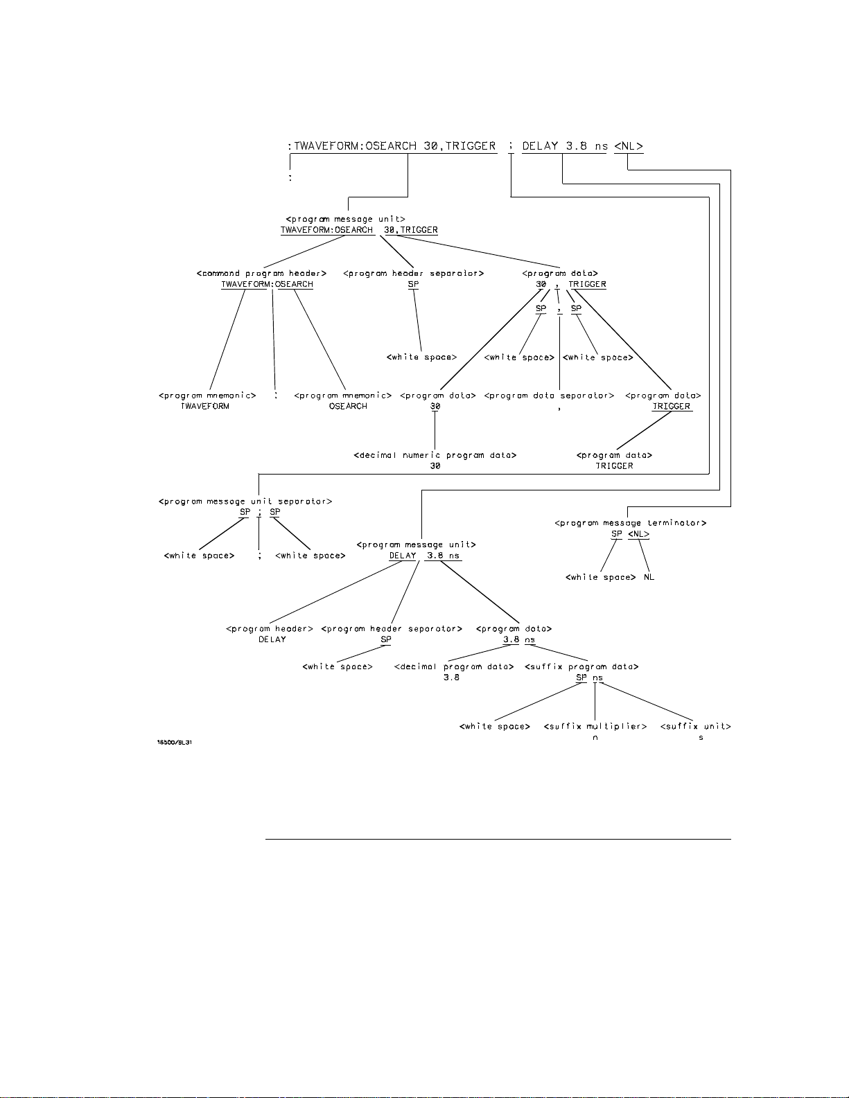
Figure 5-2
Message Commun ication and System Functions
Syntax Overview
<program message> Parse Tree
5–8
Page 75

Message Commu nication and System Functio ns
Syntax Overview
Upper/Lower Case Equivalence
Upper and lower case letters are equivalent. The mnemonic SINGLE has
the same semantic meaning as the mnemonic single.
<white space>
<white space> is defined to be one or more characters from the ASCII set of
0 - 32 decimal, excluding 10 decimal (NL). <white space> is used by several
instrument listening components of the syntax. It is usually optional, and can
be used to increase the readability of a program.
Suffix Multiplier The suffix multipliers that the instrument will accept
are shown in table 5-1.
Table 5-1
<suffix mult>
Value Mnemonic
1E18 EX
1E15 PE
1E12 T
1E9 G
1E6 MA
1E3 K
1E-3 M
1E-6 U
1E-9 N
1E-12 P
1E-15 F
1E-18 A
5–9
Page 76

Table 5-2
Message Commun ication and System Functions
Syntax Overview
Suffix Unit The suffix units that the instrument will accept are shown
in table 5-2.
<suffix unit>
Suffix Referenced Unit
V Volt
S Second
5–10
Page 77

6
Status Reporting
Page 78

Introduction
Status reporting allows you to use information about the instrument in
your programs, so that you have better control of the measurement
process. For example, you can use status reporting to determine
when a measurement is complete, thus controlling your program, so
that it does not get ahead of the instrument. This chapter describes
the status registers, status bytes and status bits defined by IEEE
488.2 and discusses how they are implemented in the
HP 1660C/CS/CP-series logic analyzers. Also in this chapter is a
sample set of steps you use to perform a serial poll over HP-IB.
The status reporting feature available over the bus is the serial poll.
IEEE 488.2 defines data structures, commands, and common bit
definitions. There are also instrument-defined structures and bits.
The bits in the status byte act as summary bits for the data structures
residing behind them. In the case of queues, the summary bit is set if
the queue is not empty. For registers, the summary bit is set if any
enabled bit in the event register is set. The events are enabled via the
corresponding event enable register. Events captured by an event
register remain set until the register is read or cleared. Registers are
read with their associated commands. The *CLS command clears all
event registers and all queues except the output queue. If *CLS is
sent immediately following a <program message terminator>, the
output queue will also be cleared.
6–2
Page 79
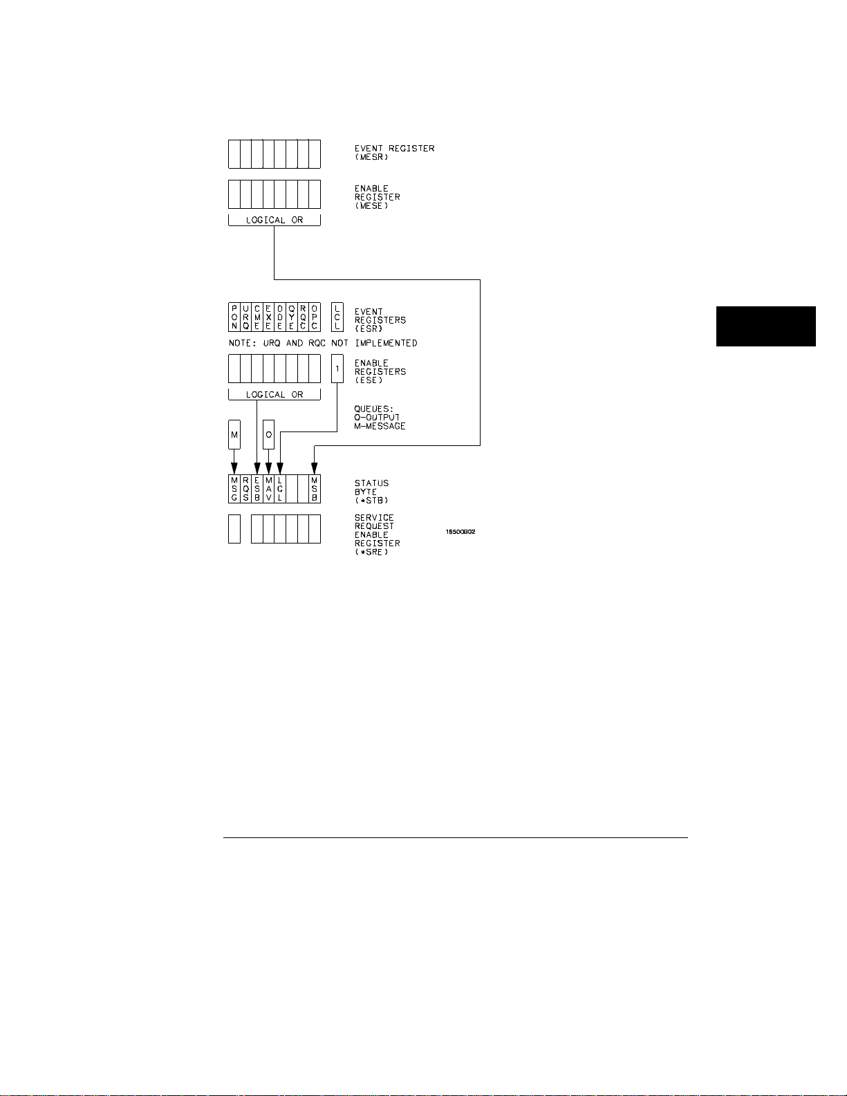
Figure 6-1
Status Repor ting
Status Byte Structures and Concepts
6–3
Page 80

Status Reporting
Event Status Register
Event Status Register
The Event Status Register is an IEEE 488.2 defined register. The bits in this
register are "latched." That is, once an event happens which sets a bit, that
bit will only be cleared if the register is read.
Service Request Enable Register
The Service Request Enable Register is an 8-bit register. Each bit enables
the corresponding bit in the status byte to cause a service request. The sixth
bit does not logically exist and is always returned as a zero. To read and
write to this register, use the *SRE? and *SRE commands.
Bit Definitions
The following mnemonics are used in figure 6-1 and in chapter 8, "Common
Commands".
MAV - message available
Indicates whether there is a response in the output queue.
ESB - event status bit
Indicates if any of the conditions in the Standard Event Status Register are
set and enabled.
MSS - master summary status
Indicates whether the device has a reason for requesting service. This bit is
returned for the *STB? query.
RQS - request service
Indicates if the device is requesting service. This bit is returned during a
serial poll. RQS will be set to 0 after being read via a serial poll (MSS is not
reset by *STB?).
6–4
Page 81
Status Repor ting
Bit Definitions
MSG - message
Indicates whether there is a message in the message queue (Not
implemented in the HP 1660C/CS/CP-series).
PON - power on
Indicates power has been turned on.
URQ - user request
Always returns a 0 from the HP 1660C/CS/CP-series.
CME - command error
Indicates whether the parser detected an error.
The error numbers and strings for CME, EXE, DDE, and QYE can be read from a
device-defined queue (which is not part of IEEE 488.2) with the query
:SYSTEM:ERROR?.
EXE - execution error
Indicates whether a parameter was out of range, or inconsistent with current
settings.
DDE - device specific error
Indicates whether the device was unable to complete an operation for device
dependent reasons.
QYE - query error
Indicates whether the protocol for queries has been violated.
RQC - request control
Always returns a 0 from the HP 1660C/CS/CP-series.
OPC - operation complete
Indicates whether the device has completed all pending operations. OPC is
controlled by the *OPC common command. Because this command can
appear after any other command, it serves as a general-purpose operation
complete message generator.
6–5
Page 82

Status Reporting
Key Features
LCL - remote to local
Indicates whether a remote to local transition has occurred.
MSB - module summary bit
Indicates that an enable event in one of the modules Status registers has
occurred.
Key Features
A few of the most important features of Status Reporting are listed in the
following paragraphs.
Operation Complete
The IEEE 488.2 structure provides one technique that can be used to find
out if any operation is finished. The *OPC command, when sent to the
instrument after the operation of interest, will set the OPC bit in the
Standard Event Status Register. If the OPC bit and the RQS bit have been
enabled, a service request will be generated. The commands that affect the
OPC bit are the overlapped commands.
Example OUTPUT XXX;"*SRE 32 ; *ESE 1" !enables an OPC service
request
Status Byte
The Status Byte contains the basic status information which is sent over the
bus in a serial poll. If the device is requesting service (RQS set), and the
controller serial-polls the device, the RQS bit is cleared. The MSS (Master
Summary Status) bit (read with *STB?) and other bits of the Status Byte are
not be cleared by reading them. Only the RQS bit is cleared when read.
The Status Byte is cleared with the *CLS common command.
6–6
Page 83
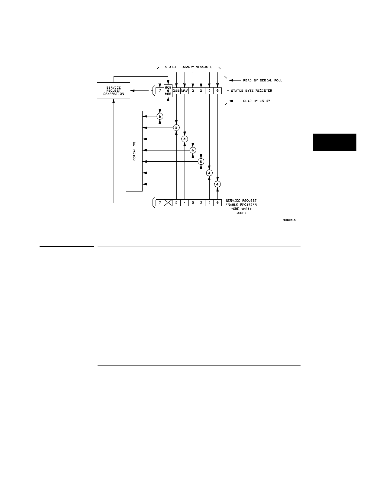
Figure 6-2
Status Repor ting
Serial Poll
Service Request Enabling
Serial Poll
The HP 1660C/CS/CP-series supports the IEEE 488.1 serial poll feature.
When a serial poll of the instrument is requested, the RQS bit is returned on
bit 6 of the status byte.
6–7
Page 84

Status Reporting
Serial Poll
Using Serial Poll (HP-IB)
This example will show how to use the service request by conducting a serial
poll of all instruments on the HP-IB bus. In this example, assume that there
are two instruments on the bus: a Logic Analyzer at address 7 and a printer at
address 1.
The program command for serial poll using HP BASIC 6.2 is Stat =
SPOLL(707). The address 707 is the address of the logic analyzer in the this
example. The command for checking the printer is Stat = SPOLL(701)
because the address of that instrument is 01 on bus address 7. This
command reads the contents of the HP-IB Status Register into the variable
called Stat. At that time bit 6 of the variable Stat can be tested to see if it is
set (bit 6 = 1).
The serial poll operation can be conducted in the following manner:
1 Enable interrupts on the bus. This allows the controller to see the
SRQ line.
2 Disable interrupts on the bus.
3 If the SRQ line is high (some instrument is requesting service) then
check the instrument at address 1 to see if bit 6 of its status register is
high.
4 To check whether bit 6 of an instruments status register is high, use
the following BASIC statement: IF BIT (Stat, 6) THEN
5 If bit 6 of the instrument at address 1 is not high, then check the
instrument at address 7 to see if bit 6 of its status register is high.
6 As soon as the instrument with status bit 6 high is found check the
rest of the status bits to determine what is required.
The SPOLL(707) command causes much more to happen on the bus than
simply reading the register. This command clears the bus automatically,
addresses the talker and listener, sends SPE (serial poll enable) and SPD
(serial poll disable) bus commands, and reads the data. For more
information about serial poll, refer to your controller manual, and
programming language reference manuals.
After the serial poll is completed, the RQS bit in the HP 1660C/CS/CP-series
Status Byte Register will be reset if it was set. Once a bit in the Status Byte
Register is set, it will remain set until the status is cleared with a *CLS
command, or the instrument is reset.
6–8
Page 85

7
Error Messages
Page 86

Introduction
This chapter lists the error messages that relate to the
HP 1660C/CS/CP-series logic analyzers.
7–2
Page 87

Device Dependent Errors
Device Dependent Errors
200 Label not found
201 Pattern string invalid
202 Qualifier invalid
203 Data not available
300 RS-232-C error
Command Errors
–100 Command error (unknown command)(generic error)
–101 Invalid character received
–110 Command header error
–111 Header delimiter error
–120 Numeric argument error
–121 Wrong data type (numeric expected)
–123 Numeric overflow
–129 Missing numeric argument
–130 Non numeric argument error (character,string, or block)
–131 Wrong data type (character expected)
–132 Wrong data type (string expected)
–133 Wrong data type (block type #D required)
–134 Data overflow (string or block too long)
–139 Missing non numeric argument
–142 Too many arguments
–143 Argument delimiter error
–144 Invalid message unit delimiter
Error Messages
7–3
Page 88

Error Messages
Execution Errors
Execution Errors
–200 Can Not Do (generic execution error)
–201 Not executable in Local Mode
–202 Settings lost due to return-to-local or power on
–203 Trigger ignored
–211 Legal command, but settings conflict
–212 Argument out of range
–221 Busy doing something else
–222 Insufficient capability or configuration
–232 Output buffer full or overflow
–240 Mass Memory error (generic)
–241 Mass storage device not present
–242 No media
–243 Bad media
–244 Media full
–245 Directory full
–246 File name not found
–247 Duplicate file name
–248 Media protected
Internal Errors
–300 Device Failure (generic hardware error)
–301 Interrupt fault
–302 System Error
–303 Time out
–310 RAM error
–311 RAM failure (hardware error)
–312 RAM data loss (software error)
–313 Calibration data loss
–320 ROM error
7–4
Page 89

–321 ROM checksum
–322 Hardware and Firmware incompatible
–330 Power on test failed
–340 Self Test failed
–350 Too Many Errors (Error queue overflow)
Query Errors
–400 Query Error (generic)
–410 Query INTERRUPTED
–420 Query UNTERMINATED
–421 Query received. Indefinite block response in progress
–422 Addressed to Talk, Nothing to Say
–430 Query DEADLOCKED
Error Messages
Query Erro rs
7–5
Page 90

7–6
Page 91

Part 2
Mainframe Commands
Page 92

Page 93

8
Common Commands
Page 94

Introduction
The common commands are defined by the IEEE 488.2 standard.
These commands must be supported by all instruments that comply
with this standard. Refer to figure 8-1 and table 8-1 for the common
commands syntax diagram.
The common commands control some of the basic instrument
functions; such as, instrument identification and reset, how status is
read and cleared, and how commands and queries are received and
processed by the instrument. The common commands are:
*CLS
•
*ESE
•
*ESR
•
*IDN
•
*IST
•
*OPC
•
*OPT
•
*PRE
•
*RST
•
*SRE
•
*STB
•
*TRG
•
*TST
•
*WAI
•
Common commands can be received and processed by the HP
1660C/CS/CP-series logic analyzers, whether they are sent over the
bus as separate program messages or within other program messages.
If an instrument subsystem has been selected and a common
command is received by the instrument, the logic analyzer will remain
in the selected subsystem.
8–2
Page 95

Common Commands
Example If the program message in this example is received by the logic
analyzer, it will initialize the disk and store the file and clear the status
information. This is not be the case if some other type of command is
received within the program message.
":MMEMORY:INITIALIZE;*CLS; STORE ’FILE ’,’DESCRIPTION’"
Example This program message initializes the disk, selects the module in slot A,
then stores the file. In this example, :MMEMORY must be sent again
to re-enter the memory subsystem and store the file.
":MMEMORY:INITIALIZE;:SELECT 1;:MMEMORY:STORE ’FILE ’,
’DESCRIPTION’"
Status Registers
Each status register has an associated status enable (mask) register.
By setting the bits in the status enable register you can select the
status information you wish to use. Any status bits that have not been
masked (enabled in the enable register) will not be used to report
status summary information to bits in other status registers.
Refer to chapter 6, "Status Reporting," for a complete discussion of
how to read the status registers and how to use the status information
available from this instrument.
Table 8-1 Common Command Parameter Values
Parameter Values
mask An integer, 0 through 255.
pre_mask An integer, 0 through 65535.
8–3
Page 96
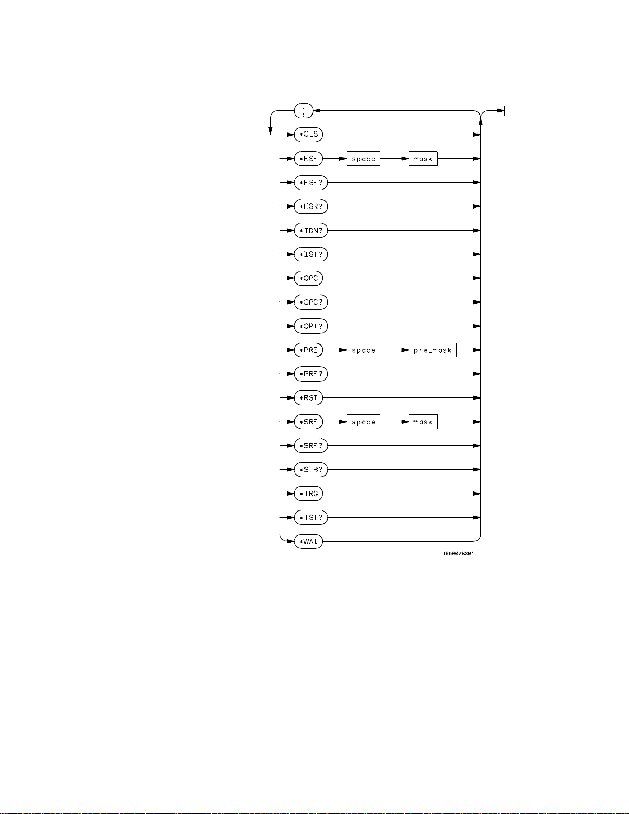
Figure 8-1
Common Commands
Common Commands Syntax Diagram
8–4
Page 97

*CLS (Clear Status)
Command *CLS
The *CLS common command clears all event status registers, queues, and
data structures, including the device defined error queue and status byte. If
the *CLS command immediately follows a <program message terminator>,
the output queue and the MAV (Message Available) bit will be cleared. Refer
to chapter 6, "Status Reporting," for a complete discussion of status.
Example OUTPUT XXX; "*CLS"
*ESE (Event Status Enable)
Command *ESE <mask>
Common Commands
*CLS (Clear Status)
The *ESE command sets the Standard Event Status Enable Register bits.
The Standard Event Status Enable Register contains a bit to enable the
status indicators detailed in table 8-2. A 1 in any bit position of the Standard
Event Status Enable Register enables the corresponding status in the
Standard Event Status Enable Register. Refer to Chapter 6, "Status
Reporting" for a complete discussion of status.
<mask> An integer from 0 to 255.
Example In this example, the *ESE 32 command will enable CME (Command Error),
bit 5 of the Standard Event Status Enable Register. Therefore, when a
command error occurs, the event summary bit (ESB) in the Status Byte
Register will also be set.
OUTPUT XXX; "*ESE 32"
Query *ESE?
The *ESE query returns the current contents of the enable register.
8–5
Page 98

Common Commands
*ESR (Event Status Register)
Returned Format <mask><NL>
Example OUTPU T XXX;"*ESE?"
Table 8-2 Standard Event Status Enable Register
Bit Position Bit Weig ht En ables
7 128 PON - Power On
6 64 URQ - User Request
5 32 CME - Command Error
4 16 EXE - Execution Error
3 8 DDE - Device Dependent Error
2 4 QYE - Query Error
1 2 RQC - Request Control
0 1 OPC - Operation Complete
*ESR (Event Status Register)
Query *ESR?
The *ESR query returns the contents of the Standard Event Status Register.
Reading the register clears the Standard Event Status Register.
Returned Format <status><NL>
<status> An integer from 0 to 255.
Example If a command error has occurred, and bit 5 of the ESE register is set, the
string variable Esr_event$ will have bit 5 (the CME bit) set.
10 OUTPUT XXX;"*ESE 32" !Enables bit 5 of the status register
20 OUTPUT XXX;"*ESR?" !Queries the status register
30 ENTER XXX; Esr_event$ !Reads the query buffer
8–6
Page 99

Common Commands
*ESR (Event Status Register)
Table 8-3 shows the Standard Event Status Register. The table details the
meaning of each bit position in the Standard Event Status Register and the
bit weight. When you read Standard Event Status Register, the value
returned is the total bit weight of all the bits that are high at the time you
read the byte.
Table 8-3
Standard Event Status Register
Bit Position Bit Weight Bit Name C o ndition
7 128 PON 0 = register read - not in power up mode
1 = power up
6 64 URQ 0 = user request - not used - always zero
5 32 CME 0 = no command errors
1 = a command eror has been detected
4 16 EXE 0 = no execution errors
1 = an execution error has been detected
3 8 DDE 0 = no device dependent error has been detected
1 = a device dependent error has been detected
2 4 QYE 0 = no query errors
1 = a query error has been detected
1 2 RQC 0 = request control - not used - always zero
0 1 OPC 0 = operation is not complete
1 = operation is c omplete
8–7
Page 100

Common Commands
*IDN (Identification Number)
*IDN (Identification Number)
Query *IDN?
The *IDN? query allows the instrument to identify itself. It returns the string:
"HEWLETT-PACKARD,1660C,0,REV <revision_code>"
The model number reflects the model you issue the command to, but the
1660CS models also return 1660C. An *IDN? query must be the last query in
a message. Any queries after the *IDN? in the program message are ignored.
Returned Format
HEWLETT-PACKAR D,1660C,0, REV <rev ision code>
<revision
code>
Example OUTPU T XXX;"*IDN?"
Four-digit code in the format XX.XX representing the current ROM revision.
*IST (Individual Status)
Query *IST?
The *IST query allows the instrument to identify itself during parallel poll by
allowing the controller to read the current state of the IEEE 488.1 defined
"ist" local message in the instrument. The response to this query is
dependent upon the current status of the instrument.
Figure 8-2 shows the *IST data structure.
Returned Format
<id> 0 or 1
<id><NL>
1 Indicates the "ist" local message is false.
0 Indicates the "ist" local message is true.
Example OUTPU T XXX;"*IST?"
8–8
 Loading...