

Page 1

Installation and Service Guide
Agilent Serial Distribution Network (SDN)
78581B Agilent CareNet Controller (ACC)
Part Number 78581-92000
Printed in the U.S.A. February 1, 2001
First Edition
Page 2

Notice
Proprietary
Information
Warranty
This document contains proprietary information that is protected by
copyright. All Rights Reserved. Reproduction, adaptation, or translation
without prior written permission is prohibited, except as allowed under the
copyright laws.
Agilent Technologies, Inc.
3000 Minuteman Road
Andover, MA 01810-1099
(978) 687-1501
Publication number
78581-92000
Printed in USA
The information contained in this document is subject to change without
notice.
Agilent Technologies makes no warranty of any kind with regard to this
material, including, but not limited to, the implied warranties or
merchantability and fitness for a particular purpose.
Agilent Technologies shall not be liable for errors contained herein or for
incidental or consequential damages in connection with the furnishing,
performance, or use of this material.
Printing History
Copyright and
Trademarks
New editions of this document will incorporate all material updated since
the previous edition.
The documentation printing date and part number indicate its current
edition. The printing date changes when a new edition is printed (minor
corrections and updates that are incorporated at reprint do not cause the
date to change). The document part number changes when extensive
technical changes are incorporated.
First Edition. . . . . . . . . . . . . . . . . . . . . . . . . . . . . February 2001
Copyright © Agilent Technologies, Inc. 2001
Page 3

Contents
1. Introduction . . . . . . . . . . . . . . . . . . . . . . . . . . . . . . . . . . . . . . . . . . . . 1-1
SDN System Description . . . . . . . . . . . . . . . . . . . . . . . . . . . . . . . . . . . . . . . . . . . . . . . . 1-1
SDN Components . . . . . . . . . . . . . . . . . . . . . . . . . . . . . . . . . . . . . . . . . . . . . . . . . . 1-1
SDN Operation. . . . . . . . . . . . . . . . . . . . . . . . . . . . . . . . . . . . . . . . . . . . . . . . . . . . .1-1
Operating Reliability — Failure/Restart . . . . . . . . . . . . . . . . . . . . . . . . . . . . . . . . 1-3
SDN Configurations . . . . . . . . . . . . . . . . . . . . . . . . . . . . . . . . . . . . . . . . . . . . . . . . 1-3
Agilent CareNet Controller (ACC), Model 78581B . . . . . . . . . . . . . . . . . . . . . . . . . . . 1-4
ACC Controls and Indicators . . . . . . . . . . . . . . . . . . . . . . . . . . . . . . . . . . . . . . . . . 1-5
ACC Servicing . . . . . . . . . . . . . . . . . . . . . . . . . . . . . . . . . . . . . . . . . . . . . . . . . . . . . 1-5
Cables, Wall Boxes, and Faceplates . . . . . . . . . . . . . . . . . . . . . . . . . . . . . . . . . . . . . . . 1-6
Branch Cables . . . . . . . . . . . . . . . . . . . . . . . . . . . . . . . . . . . . . . . . . . . . . . . . . . . . . 1-6
Local Distribution Cables (LDC) . . . . . . . . . . . . . . . . . . . . . . . . . . . . . . . . . . . . . . 1-6
Wall Boxes and Face Plates . . . . . . . . . . . . . . . . . . . . . . . . . . . . . . . . . . . . . . . . . .1-6
SDN Components . . . . . . . . . . . . . . . . . . . . . . . . . . . . . . . . . . . . . . . . . . . . . . . . . . . . . . 1-7
78599AI SDN Cabling Installation Kits . . . . . . . . . . . . . . . . . . . . . . . . . . . . . . . . .1-7
M3199AI Installation Materials . . . . . . . . . . . . . . . . . . . . . . . . . . . . . . . . . . . . . . . 1-8
M3180A Wall Mount Kit . . . . . . . . . . . . . . . . . . . . . . . . . . . . . . . . . . . . . . . . . . . . . 1-8
Intended Use of Device . . . . . . . . . . . . . . . . . . . . . . . . . . . . . . . . . . . . . . . . . . . . . . . . . 1-8
2. Theory of Operation . . . . . . . . . . . . . . . . . . . . . . . . . . . . . . . . . . . . . 2-1
Overview . . . . . . . . . . . . . . . . . . . . . . . . . . . . . . . . . . . . . . . . . . . . . . . . . . . . . . . . . . . . .2-1
SDN Theory of Operation . . . . . . . . . . . . . . . . . . . . . . . . . . . . . . . . . . . . . . . . . . . . . . .2-2
SDN General Description . . . . . . . . . . . . . . . . . . . . . . . . . . . . . . . . . . . . . . . . . . . .2-2
Logic Convention. . . . . . . . . . . . . . . . . . . . . . . . . . . . . . . . . . . . . . . . . . . . . . . . . . .2-3
SDN Topology . . . . . . . . . . . . . . . . . . . . . . . . . . . . . . . . . . . . . . . . . . . . . . . . . . . . . 2-5
Applications of SDN Operation . . . . . . . . . . . . . . . . . . . . . . . . . . . . . . . . . . . . . . . . . . 2-6
Instrument Communication on the SDN . . . . . . . . . . . . . . . . . . . . . . . . . . . . . . . 2-6
SDN Timing Overview . . . . . . . . . . . . . . . . . . . . . . . . . . . . . . . . . . . . . . . . . . . . . . . 2-7
Autopoll Mode . . . . . . . . . . . . . . . . . . . . . . . . . . . . . . . . . . . . . . . . . . . . . . . . . . . . . 2-8
SDN Data Structure — System and Instrument Messages . . . . . . . . . . . . . . . . . . . . . 2-9
System Messages . . . . . . . . . . . . . . . . . . . . . . . . . . . . . . . . . . . . . . . . . . . . . . . . . . . 2-9
Instrument Messages. . . . . . . . . . . . . . . . . . . . . . . . . . . . . . . . . . . . . . . . . . . . . . . 2-10
SDN Normal Operation . . . . . . . . . . . . . . . . . . . . . . . . . . . . . . . . . . . . . . . . . . . . . . . . 2-11
SDN Data Timing Specifications . . . . . . . . . . . . . . . . . . . . . . . . . . . . . . . . . . . . . 2-11
Instrument Status Message . . . . . . . . . . . . . . . . . . . . . . . . . . . . . . . . . . . . . . . . . 2-11
SDN/Autopoll . . . . . . . . . . . . . . . . . . . . . . . . . . . . . . . . . . . . . . . . . . . . . . . . .2-12
ONLINE/OFFLINE . . . . . . . . . . . . . . . . . . . . . . . . . . . . . . . . . . . . . . . . . . . . . 2-12
NETWORK/LOCAL . . . . . . . . . . . . . . . . . . . . . . . . . . . . . . . . . . . . . . . . . . . . . 2-12
SDN Status and Error Conditions . . . . . . . . . . . . . . . . . . . . . . . . . . . . . . . . . . . . 2-12
ACC Error Conditions — SDN Failure Detection . . . . . . . . . . . . . . . . . . . . . . . . 2-13
ACC Theory of Operation . . . . . . . . . . . . . . . . . . . . . . . . . . . . . . . . . . . . . . . . . . . . . . 2-14
Main PCB (78581-60200) . . . . . . . . . . . . . . . . . . . . . . . . . . . . . . . . . . . . . . . . . . . 2-14
Transition Board (78581-61253) . . . . . . . . . . . . . . . . . . . . . . . . . . . . . . . . . . . . . 2-15
Power Supply (M2604-60002) . . . . . . . . . . . . . . . . . . . . . . . . . . . . . . . . . . . . . . . 2-15
Contents-1
Page 4

3. SDN and ACC System Level Troubleshooting . . . . . . . . . . . . . . . . . 3-1
SDN Troubleshooting Overview . . . . . . . . . . . . . . . . . . . . . . . . . . . . . . . . . . . . . . . . . . 3-1
Troubleshooting Resources, Tools, and Equipment . . . . . . . . . . . . . . . . . . . . . . . . . . 3-3
SDN Troubleshooting Flowchart . . . . . . . . . . . . . . . . . . . . . . . . . . . . . . . . . . . . . . 3-3
STEP #1: Review Customer’s System Configuration . . . . . . . . . . . . . . . . . . . . . . 3-5
STEP #2: Examine System and Gather Symptoms . . . . . . . . . . . . . . . . . . . . . . . 3-5
SDN Connections . . . . . . . . . . . . . . . . . . . . . . . . . . . . . . . . . . . . . . . . . . . . . . . 3-5
SDN Error Messages and Error Codes . . . . . . . . . . . . . . . . . . . . . . . . . . . . . . 3-5
Diagnose the Problem as SDN or Non-SDN . . . . . . . . . . . . . . . . . . . . . . . . . .3-6
Noisy Branch. . . . . . . . . . . . . . . . . . . . . . . . . . . . . . . . . . . . . . . . . . . . . . . . . . .3-6
SDN and Non-SDN Related Problems. . . . . . . . . . . . . . . . . . . . . . . . . . . . . . . 3-7
Action. . . . . . . . . . . . . . . . . . . . . . . . . . . . . . . . . . . . . . . . . . . . . . . . . . . . . . . . .3-7
STEP #3: Evaluate the Breadth of the Problem . . . . . . . . . . . . . . . . . . . . . . . . . . 3-8
Action. . . . . . . . . . . . . . . . . . . . . . . . . . . . . . . . . . . . . . . . . . . . . . . . . . . . . . . . .3-8
STEP #4: Self-Test Check of SDN Interface Circuitry . . . . . . . . . . . . . . . . . . . . . 3-8
STEP #5: Isolating a Problem on A Local Distribution Network (LDN)
With Two or More Instruments . . . . . . . . . . . . . . . . . . . . . . . . . . . . . . . . . . . . . . 3-11
Miscellaneous Items . . . . . . . . . . . . . . . . . . . . . . . . . . . . . . . . . . . . . . . . . . . . . . .3-12
Recap of Troubleshooting Procedures: . . . . . . . . . . . . . . . . . . . . . . . . . . . . . . . .3-12
Reverification Instructions. . . . . . . . . . . . . . . . . . . . . . . . . . . . . . . . . . . . . . . . . . 3-13
Cable Verification Procedures. . . . . . . . . . . . . . . . . . . . . . . . . . . . . . . . . . . . 3-13
Hardware Problems . . . . . . . . . . . . . . . . . . . . . . . . . . . . . . . . . . . . . . . . . . . . 3-14
Verify Instrument End of the Branch Cable . . . . . . . . . . . . . . . . . . . . . . . . 3-14
Verify Proper Operation of Priority Wires . . . . . . . . . . . . . . . . . . . . . . . . . .3-15
SDN Bedside:. . . . . . . . . . . . . . . . . . . . . . . . . . . . . . . . . . . . . . . . . . . . . . . . . . 3-15
Ground Check Procedure. . . . . . . . . . . . . . . . . . . . . . . . . . . . . . . . . . . . . . . . 3-16
4. ACC Maintenance . . . . . . . . . . . . . . . . . . . . . . . . . . . . . . . . . . . . . . . 4-1
ACC Maintenance . . . . . . . . . . . . . . . . . . . . . . . . . . . . . . . . . . . . . . . . . . . . . . . . . . . . . . 4-1
ACC Failure, Power Up, and Power Down Procedures. . . . . . . . . . . . . . . . . . . . 4-1
5. Parts List. . . . . . . . . . . . . . . . . . . . . . . . . . . . . . . . . . . . . . . . . . . . . . . 5-1
Part Numbers . . . . . . . . . . . . . . . . . . . . . . . . . . . . . . . . . . . . . . . . . . . . . . . . . . . . . . . . . 5-1
6. Component Installation and Disassembly Procedures . . . . . . . . . . 6-1
Overview . . . . . . . . . . . . . . . . . . . . . . . . . . . . . . . . . . . . . . . . . . . . . . . . . . . . . . . . . . . . .6-1
Typical SDN System Interconnecting Parts . . . . . . . . . . . . . . . . . . . . . . . . . . . . .6-1
Installation Responsibilities—Customer and Agilent Technologies . . . . . . . . . . . . . 6-3
Customer Installation Responsibilities . . . . . . . . . . . . . . . . . . . . . . . . . . . . . . . . . 6-3
Agilent Installation Responsibilities . . . . . . . . . . . . . . . . . . . . . . . . . . . . . . . . . . . 6-4
7. Site Preparation/Installation Checklists . . . . . . . . . . . . . . . . . . . . . 7-1
Introduction . . . . . . . . . . . . . . . . . . . . . . . . . . . . . . . . . . . . . . . . . . . . . . . . . . . . . . . . . .7-1
Verification Procedures . . . . . . . . . . . . . . . . . . . . . . . . . . . . . . . . . . . . . . . . . . . . . . . . . 7-8
Overview of SDN/ACC Installation and System
Communication Verification Procedures . . . . . . . . . . . . . . . . . . . . . . . . . . . . . . . 7-8
Planning and Configuration Review . . . . . . . . . . . . . . . . . . . . . . . . . . . . . . . . . . .7-8
Standalone Instrument Verification and Installation . . . . . . . . . . . . . . . . . . . . . 7-8
Contents-2
Page 5

8. Installation. . . . . . . . . . . . . . . . . . . . . . . . . . . . . . . . . . . . . . . . . . . . . 8-1
SDN Installation . . . . . . . . . . . . . . . . . . . . . . . . . . . . . . . . . . . . . . . . . . . . . . . . . . . . . . 8-1
SDN Wiring Installation. . . . . . . . . . . . . . . . . . . . . . . . . . . . . . . . . . . . . . . . . . . . . 8-1
Instrument Connection to the SDN . . . . . . . . . . . . . . . . . . . . . . . . . . . . . . . . . . . 8-1
System Communication Verification . . . . . . . . . . . . . . . . . . . . . . . . . . . . . . . . . . 8-1
Practical Checks . . . . . . . . . . . . . . . . . . . . . . . . . . . . . . . . . . . . . . . . . . . . . . . . . . . 8-1
Test and Inspection Procedures . . . . . . . . . . . . . . . . . . . . . . . . . . . . . . . . . . . . . . 8-2
When to Perform . . . . . . . . . . . . . . . . . . . . . . . . . . . . . . . . . . . . . . . . . . . . . . . . . . 8-4
Installation Tools, Materials, and Equipment . . . . . . . . . . . . . . . . . . . . . . . . . . . 8-4
SDN Installation Restrictions and Limitations . . . . . . . . . . . . . . . . . . . . . . . . . . 8-4
ACC . . . . . . . . . . . . . . . . . . . . . . . . . . . . . . . . . . . . . . . . . . . . . . . . . . . . . . . . . . 8-5
Cables . . . . . . . . . . . . . . . . . . . . . . . . . . . . . . . . . . . . . . . . . . . . . . . . . . . . . . . . 8-5
Wall Boxes . . . . . . . . . . . . . . . . . . . . . . . . . . . . . . . . . . . . . . . . . . . . . . . . . . . . 8-6
ACC Mounting Location. . . . . . . . . . . . . . . . . . . . . . . . . . . . . . . . . . . . . . . . . . . . . 8-6
Rack Mounting . . . . . . . . . . . . . . . . . . . . . . . . . . . . . . . . . . . . . . . . . . . . . . . . . 8-6
Service Access . . . . . . . . . . . . . . . . . . . . . . . . . . . . . . . . . . . . . . . . . . . . . . . . . 8-6
AC Power Source . . . . . . . . . . . . . . . . . . . . . . . . . . . . . . . . . . . . . . . . . . . . . . . 8-6
Environmental Conditions . . . . . . . . . . . . . . . . . . . . . . . . . . . . . . . . . . . . . . . 8-7
Important Instructions . . . . . . . . . . . . . . . . . . . . . . . . . . . . . . . . . . . . . . . . . . . . . 8-7
ACC Wall Mounting Procedures and Power Installation . . . . . . . . . . . . . . . . . . . . . 8-8
Plywood Panel Mounting Procedures — Customer’s Responsibility . . . . . . . . . 8-8
ACC Wall Mounting Procedures . . . . . . . . . . . . . . . . . . . . . . . . . . . . . . . . . . . . . . 8-8
Install Cable Enclosures, Wall Boxes, and Branch Cables . . . . . . . . . . . . . . . . . . . . 8-9
Install Branch Cable Enclosures. . . . . . . . . . . . . . . . . . . . . . . . . . . . . . . . . . . . . . 8-9
Selecting Conduit Size . . . . . . . . . . . . . . . . . . . . . . . . . . . . . . . . . . . . . . . . . . . . . . 8-9
Formula . . . . . . . . . . . . . . . . . . . . . . . . . . . . . . . . . . . . . . . . . . . . . . . . . . . . . 8-10
Example . . . . . . . . . . . . . . . . . . . . . . . . . . . . . . . . . . . . . . . . . . . . . . . . . . . . . 8-10
Install Standard NEMA Switch Wall Boxes . . . . . . . . . . . . . . . . . . . . . . . . . . . . 8-11
Install Branch Cables . . . . . . . . . . . . . . . . . . . . . . . . . . . . . . . . . . . . . . . . . . . . . . 8-11
SDC Standard System Distribution Cable . . . . . . . . . . . . . . . . . . . . . . . . . . . . . 8-12
XSDC Extended System Distribution Cable . . . . . . . . . . . . . . . . . . . . . . . . . . . 8-12
Unshielded Twisted Pair Distribution Cable . . . . . . . . . . . . . . . . . . . . . . . . . . . 8-12
SDC and XSDC Wall Box Connections. . . . . . . . . . . . . . . . . . . . . . . . . . . . . . . . 8-12
SDN on UTP Wall Boxes Connections . . . . . . . . . . . . . . . . . . . . . . . . . . . . . . . . 8-15
UTP Connections . . . . . . . . . . . . . . . . . . . . . . . . . . . . . . . . . . . . . . . . . . . . . . . . . 8-15
Parts Required . . . . . . . . . . . . . . . . . . . . . . . . . . . . . . . . . . . . . . . . . . . . . . . . 8-16
Equipment Needed . . . . . . . . . . . . . . . . . . . . . . . . . . . . . . . . . . . . . . . . . . . . 8-16
Procedures . . . . . . . . . . . . . . . . . . . . . . . . . . . . . . . . . . . . . . . . . . . . . . . . . . . . . . . . . . 8-18
ACC Procedures (78581B). . . . . . . . . . . . . . . . . . . . . . . . . . . . . . . . . . . . . . . . . . 8-18
Perform Final Operational Check . . . . . . . . . . . . . . . . . . . . . . . . . . . . . . . . 8-18
Serial Communication Controller (SCC) Procedures (78581A) . . . . . . . . . . . 8-19
Terminate UTP Cable at Patch Panel. . . . . . . . . . . . . . . . . . . . . . . . . . . . . . 8-19
Terminate UTP Cable at Wall Box . . . . . . . . . . . . . . . . . . . . . . . . . . . . . . . . 8-20
Qualify UTP Cable . . . . . . . . . . . . . . . . . . . . . . . . . . . . . . . . . . . . . . . . . . . . . 8-21
Install Local Distribution Cables . . . . . . . . . . . . . . . . . . . . . . . . . . . . . . . . . . . . 8-23
Connect LDC from Wall Box to Instrument(s) . . . . . . . . . . . . . . . . . . . . . . . . . 8-24
Terminate Variable Length LDC . . . . . . . . . . . . . . . . . . . . . . . . . . . . . . . . . . . . . 8-25
Terminate SDC and XSDC Connections. . . . . . . . . . . . . . . . . . . . . . . . . . . . . . . 8-26
Contents-3
Page 6

9. SDN/ACC System Safety . . . . . . . . . . . . . . . . . . . . . . . . . . . . . . . . . . 9-1
Compliance with IEC 60601-1-1 . . . . . . . . . . . . . . . . . . . . . . . . . . . . . . . . . . . . . . . . . . 9-1
Device Grounding on the SDN . . . . . . . . . . . . . . . . . . . . . . . . . . . . . . . . . . . . . . . . . . .9-2
10. SDN/ACC Specifications . . . . . . . . . . . . . . . . . . . . . . . . . . . . . . . . 10-1
SDN Specifications . . . . . . . . . . . . . . . . . . . . . . . . . . . . . . . . . . . . . . . . . . . . . . . . . . . .10-1
ACC Specifications. . . . . . . . . . . . . . . . . . . . . . . . . . . . . . . . . . . . . . . . . . . . . . . . . . . .10-3
Cleaning. . . . . . . . . . . . . . . . . . . . . . . . . . . . . . . . . . . . . . . . . . . . . . . . . . . . . . . . . . . . .10-4
System Symbols . . . . . . . . . . . . . . . . . . . . . . . . . . . . . . . . . . . . . . . . . . . . . . . . . . . . . .10-4
Contacts. . . . . . . . . . . . . . . . . . . . . . . . . . . . . . . . . . . . . . . . . . . . . . . . . . . . . . . . . . . . .10-5
Contents-4
Page 7

SDN System Description
The Serial Distribution Network (SDN) is a local area communications
network designed to share patient physiological parameters and other
data among bedside instruments, information centers (IC), recorders,
thermal printers, computer systems, and other information systems
connected to the system. The SDN is a digital communications network
that allows real-time transfer of digitized patient data between these
instruments. The communication protocol, data formatting, and hardware
implementation is intended to be flexible enough to accommodate a
variety of communication needs in the patient monitoring environment for
present and future expansion.
Introduction
Section 1: Introduction
SDN
Components
SDN Operation
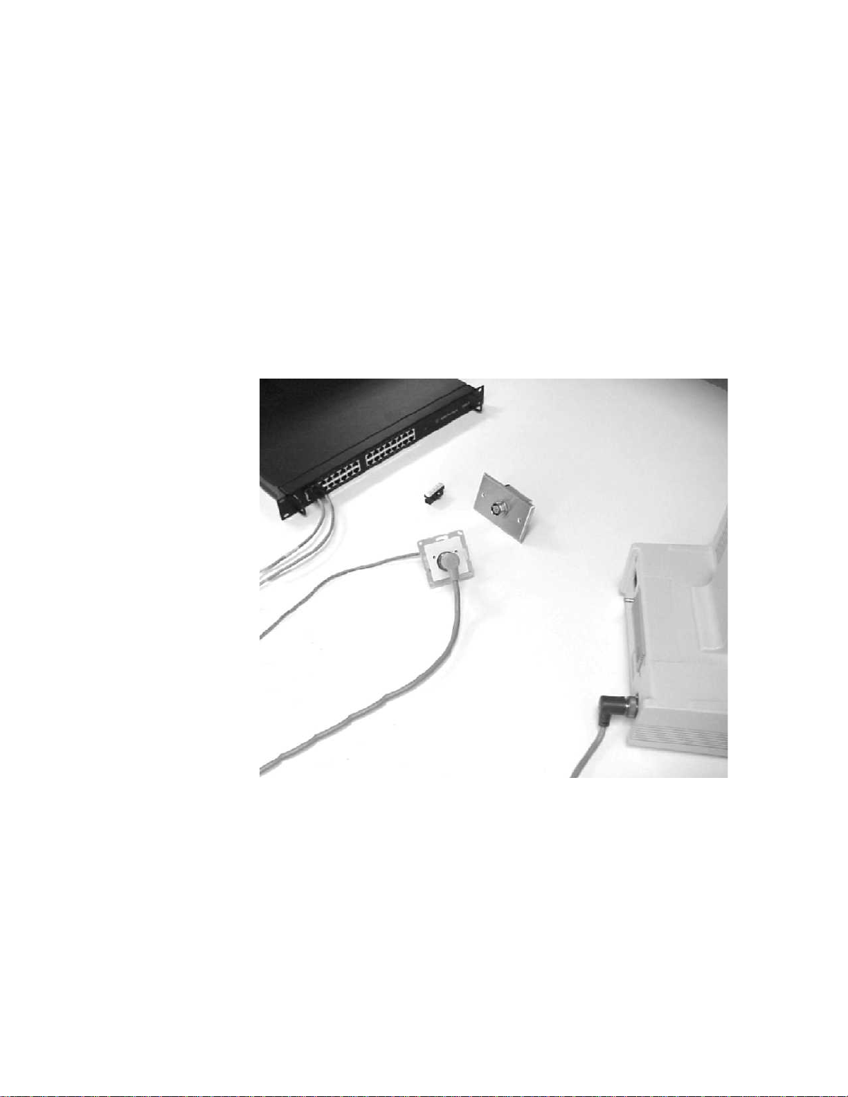
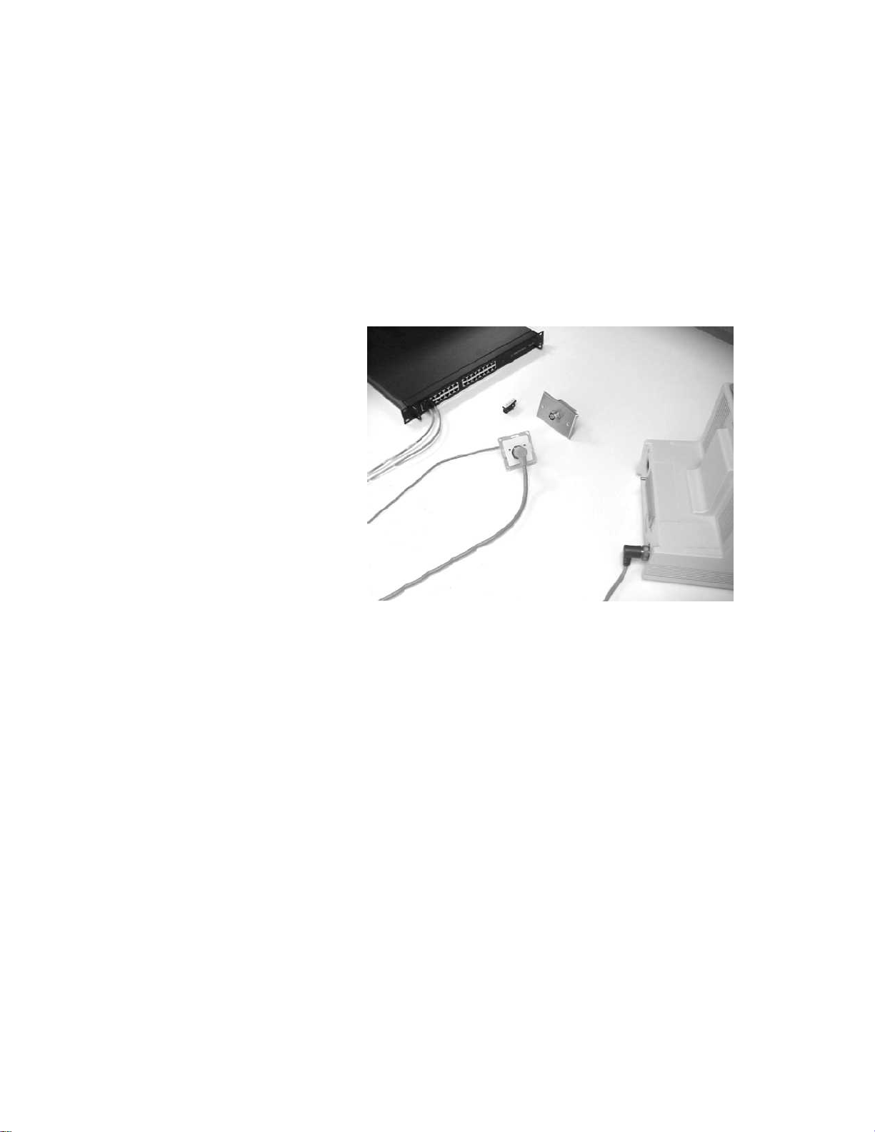
The components of the SDN consist of the model 78581B Agilent CareNet
Controller (ACC), the SDN interface circuitry located within each
instrument connected to the SDN, and the system distribution cables
(branch cables), local distribution cables, and the associated wallbox
hardware, connectors and receptacles. The components of the SDN are
shown on page 1-2, and a typical SDN configuration is illustrated in Figure
1-2 on page 1-3.
The SDN functions automatically without user interaction and without
direct patient connections. Digitized patient information from each
instrument (branch) is transmitted serially at regular intervals (called poll
cycles) over branch cables to the ACC. The ACC sequentially receives,
synchronizes, and rebroadcasts the digitized patient information to all
instruments connected to the SDN. This patient data is received for use by
each instrument via the SDN interface circuity resident in each
instrument. Patient data are not restricted or allocated by the network,
but are accepted from, and transmitted to, all instruments within the
system. Each instrument decides for itself which patient information it
wants to acquire and process. Each instrument gets a chance to transmit
and receive patient information every poll cycle. A poll cycle lasts 32 ms,
thus, there are approximately 32 poll cycles per second.
Digitized patient information transmitted over the SDN may be either
waveforms (for ECG, pressure, and respiration) or parametric information
(for heart rate/pulse, pressure valves, and respiration rate). The SDN data
transmission rate of 3.6 Mbits can provide up to 7700 usable 12-bit data
1-1
Page 8
SDN System Description
words per 32-millisecond poll cycle. The SDN is a half-duplex network
using terminated shielded twisted pair cable(s). All data is transmitted
differentially and serially using block code modulation. A detailed
description of the SDN system theory of operation is given in a subsequent
section of this manual.
Within the connected instruments, SDN interface circuitry provides the
link between the serial digital network, and the instrument connected to
the SDN (except the ACC) has basically the same interface circuitry, most
of which is contained on a custom integrated circuit called the SDN
Interface Circuit Chip (SIC Chip). A detailed description of the SIC Chip
theory of operation is given in a subsequent section of this manual.
1-2
Figure 1-1. SDN Components
Page 9

Introduction
CCU/PCU ER
AIC
8
Bedsides
4 Telepaks
015
16 31
Tele
Mainframe
Figure 1-2. Typical SDN Configuration
Operating Reliability — Failure/Restart
Power Failure: ACC operation resumes automatically after power
restoration. Loss of power to the ACC will not affect local operation
between instruments on a branch that do have power. Loss of power at
one instrument on a branch will not disrupt system communication of
other instruments on the same branch or any other branch of the network.
ACC
AIC
4 Bedsides
AIC
4 Bedsides
4 Telepaks
SDN Configurations
Various combinations of patient monitors and patient information centers
may be connected to the ACC providing the system is configured within
the certain restrictions and limitations.
The ACC can accommodate up to 32 separate branch cables emanating
from it to the wall boxes (instruments). Of the 32 total branches, 24 may
connect to HP and Agilent bedside instruments (one patient per branch—
see note below), 6 may connect to information centers, and 2 may connect
to computerized systems. Refer to the installation section of this manual
for a complete listing of SDN System, ACC, cables, and wall boxes
restrictions and limitations.
1-3
Page 10

Agilent CareNet Controller (ACC), Model 78581B
Agilent CareNet Controller (ACC), Model 78581B
The Agilent CareNet Controller (ACC), model 78581B, is the active node—
in essence the heart—of the Serial Distribution Network (SDN). The
primary functions of the ACC are to provide the physical system
communications link to the instruments connected to the SDN, to establish
the SDN data polling cycles, and to control the data flow, timing,
synchronization, and distribution throughout the system.
The ACC functions in conjunction with the SDN Interface Circuitry located
within each instrument connected to the SDN, and with the system
distribution cables (branch cables), local distribution cables, and the
associated wallbox hardware, connectors and receptacles. A typical SDN
system configuration is illustrated in Figure 1-2 on page 1-3.
Once each poll cycle, data from each instrument is transmitted over the
branch cables to the ACC. All this data are received in sequence,
synchronized, and controlled by the ACC, then transmitted (broadcast)
simultaneously to all of the instruments connected to the SDN during each
32-millisecond poll cycle. The data sent over the SDN bus is received for
use by each instrument via the SDN interface circuitry residing in each
instrument. The ACC cannot store, restrict, or allocate specific
distribution of SDN data.
The ACC controls the data communication sequence during the 32millisecond poll cycle by issuing a variety of system messages that
originate in the ACC. A complete description of system messages,
instrument messages, the SDN data communicating sequence and SDN bus
direction control is described in the SDN system theory of operation
section of this manual.
Additionally, the ACC performs some basic fault detection isolation to
ensure reliability of SDN system communications. Also included in the
ACC are resident self-diagnostic routines for fault detection,
troubleshooting, and servicing of the ACC.
The ACC consists of a metal chassis with cover, a Power Supply Assembly,
a Terminal Interconnect PC board, and a Control/Driver PC board. The
model 78581B Agilent CareNet Controller is illustrated on in Figure 1-3 on
page 1-5.
The Control/Driver PC board contains all the electronic circuitry required
to control the data flow, timing, and distribution of SDN data throughout
the system.
The Terminal Interconnect PC board contains the RJ-45 connection to
connect the branch cables to the ACC, and the signal feed-through ribbon
cables to the Control/Driver PC board.
The Power Supply assembly contains the power ON/OFF indicator, and a
5-volt linear DC voltage supply used to power the circuitry on the Control/
1-4
Page 11

Introduction
Driver PC board. This model of the ACC does not have a power ON/OFF
switch. Power comes on as soon as it’s connected to AC by power cord. To
disconnect the power, remove the plug from the wall receptacle.
ACC Controls and Indicators
There are no operator controls located on the ACC. Once the power cord is
connected and the ACC is running properly, no operator adjustments are
necessary.
The green power ON/OFF indicator is visible on the rear. When
illuminated, it indicates 5-volt power is available from the ACC power
supply.
ACC Servicing
The ACC has been designed for ease of servicing. PC board and assembly
replacement is the primary method of repair. Troubleshooting tests and
integrity routines are specified in detail the ACC Troubleshooting section
of this manual. Complete disassembly procedures of the ACC are
described in the Installation section of this manual.
Figure 1-3. Agilent 78581B Agilent CareNet Controller
1-5
Page 12

Cables, Wall Boxes, and Faceplates
Cables, Wall Boxes, and Faceplates
Branch Cables
There are three types of branch cables that are permanently installed to
provide long distance connection between the ACC and the wall box; the
standard System Distribution Cable (SDC), the Extended System
Distribution Cable (XSDC), and Category 5 Unshielded Twisted Pair
(UTP).
The length of Unshielded Twisted Pair runs must be less than 90 meters
(295 ft.). The length of each standard SDC must be less than 152 meters
(500 ft.). The length of each XSDC must be less than 304 meters (1000 ft.).
Only two XSDC runs are allowable per ACC. Branch cable runs must be
continuous; no splicing or mixing cable types is allowed.
Local Distribution Cables (LDC)
The SDN allows ease and flexibility of user placement of instruments.
Local distribution cables (LDC) must be used for local serial connection
from the wall box/face plate to the instrument, and to other instruments.
The LDC allows bedside instruments to be easily interchanged simply by
connecting them to their new locations.
Wall Boxes and Face Plates
Wall Boxes: only standard size, NEMA, single- or dual-gang, switch wall
boxes with conduit knockouts (KOs) may be used. The depth of the wall
box must be at least 7.0 cm (2.75 in). Wall boxes are usually supplied by
the customer; however, two types are available from Agilent Technologies.
Face Plates: Pre-punched, NEMA, single- or dual-gang faceplates for the
SDN; SDN on UTP US and European wall boxes. Faceplates are included
with the wall box connector kits.
1-6
Page 13

SDN Components
Introduction
Installation of a complete Serial Distribution Network requires the
ordering and selection of several instruments, SDN system components
and options. These include the model 78581B ACC and options from the
78599AI/Cabling Installation Kit to provide Local Distribution Cables
(LDC) and connector hardware. Branch cables are ordered separately
using their associated Agilent part number.
Refer to the Installation section of this manual for a complete description
of the installation instructions and responsibilities for properly installing
the ACC, the cables, and the wall boxes. The general SDN instrument
interconnection procedures are also given in the installation section;
however, the specific details of instrument wiring procedures and ‘tuning”
the instruments into the SDN communications network are explained in
detail in the associated instrument’s service manual.
The ACC may be mounted on a standard 19 inch telecommunications rack.
It may also be wall mounted on a properly prepared wall, using the wall
mount kit (M3180AI),
within the specified length limitations. No special tools are required for
installation—only screw drivers, cable strippers, and pliers are needed.
Environmental conditions, service access requirements, and free space
surrounding the ACC are detailed in the Installation section of this
manual.
that permits the length of each branch cable to be
System Distribution Cable (SDC) 100-ft. reel
Extended System
Distribution Cables (XSDC)
UTP Category 5 Orange 1000-ft. reel 8120-6770
78599AI SDN Cabling Installation Kits
— J01 Single Gang SDN Face Plate/Connector Kit
— J02 Dual Gang SDN Face Plate/Connector Kit
— J12 SDN/UTP Single Wall Box Quantity 1
— J13 SDP/UTP Single Wall Box Quantity 8
— J14 SDN/UTP Dual Wall Box Quantity 1
— J15 SDN/UTP Dual Wall Box Quantity 8
Table 1-1: SDN Branch Cables
250-ft. reel
500-ft. reel
750-ft. reel
1000-ft. reel
8120-3502
8120-3775
8120-3774
8120-3777
8120-3776
1-7
Page 14

Intended Use of Device
— JJ1 SDN on UTP parts (European) Quantity 1
— JJ2 SDN on UTP parts (European) Quantity 8
— J03 3-Foot Local Distribution Cable (LDC)(81 20-3591)
— J06 6-Foot Local Distribution Cable (LDC)(81 20-3587)
— J10 10-Foot Local Distribution Cable (LDC)(8120-3588)
— J20 20-Foot Local Distribution Cable (LDC)(8120-3589)
— J50 50-Foot Variable Length LDC Kit
— J52 Extra SDN Connectors (Two)
— J54 Fifty Feet of Unterminated LDC
M3199AI Installation Materials
— P01 UTP Plenum (Orange) Cat. 5 Cable 1000 Feet
M3180A Wall Mount Kit
Intended Use of Device
The Signal Distribution Network (SDN) allows the sharing of patient
physiological parameters and other electronic data among bedside
instruments, central station processors and displays, recorders, thermal
printers, and other computerized systems.
Warning
United States Federal Law restricts this device to sale by or on the
order of a physician.
This product is not suitable for installation in the patient care
vicinity.
— J03 RJ45 to SDN Cable Connector
— A14 Wall Mount Kit (78581-61257)
1-8
Page 15

Overview
Theory of Operation
Section 2: Theory of
Operation
Theory of operation consists of two distinct subsections:
• SDN Theory of Operation
• ACC Theory of Operation
SDN Theory of Operation describes the overall system Serial Distribution
Network (SDN), its normal operating characteristics, applications, and
error conditions, the format of the SDN digital data, and the SDN system
communications protocol as well as the local distribution network (LDN)
communications protocol. The SDN system communication protocol and
data formatting assures compatibility between a variety of different
instruments communicating together over the SDN. The communication
protocol and hardware implementation is intended to be flexible enough
to accommodate a variety of communication needs in the patient
monitoring environment for the present and for future expansion.
ACC Theory of Operation describes the detailed operating theory of the
Agilent CareNet Controller (ACC). Included in this section are functional
descriptions of the Power Supply Assembly, the Terminal Interconnect PC
board, and the detailed operating principles of the Control/Driver PC
board which includes the transmit/receive driver circuitry, the retiming
circuitry, and the control circuitry.
2-1
Page 16

SDN Theory of Operation
SDN Theory of Operation
SDN General Description
The Serial Distribution Network (SDN) is a digital communications
network designed to share patient physiological parameters and other
data among all instruments connected directly to the SDN.
The SDN uses cables containing a twisted shielded pair of wires to connect
the instruments to the Agilent CareNet Controller (ACC). Digitized patient
data is transmitted SERIALLY through the wires of the NETWORK. The
ACC circuitry manages the timing and DISTRIBUTION of the digital
patient data. Hence, it is appropriately named the SERIAL DISTRIBUTION
NETWORK.
The SDN is a half-duplex network using terminated shielded twisted pair
cable(s) to carry serial digital data. All SDN data is transmitted
differentially and serially using block code modulation. Brief explanations
of the SDN terms are given below.
Term Definition
SDN Data Physiological information such as parameters or
waveforms, or non-physiological information such
as bed labels, annotation, alarm messages, or timeof-day.
Digital Using binary logic where a high voltage level is
called a one (1) and a low voltage level is called a
zero (0).
Serial A string of ones (1) and zeros (0) in a row create
defined words, similar to alphabetic letters used to
define known words. However, the SDN words are
all the same length. These words are combined to
make up messages. Different messages have
different lengths.
Half-Duplex Signals move in one direction at a time over the
data wires. Instruments using the SDN never talk
and listen at the same time.
Block Coded A digital coding scheme that facilitates sending
serial digital data by insuring not too many ones (1)
or zeros (0) are transmitted. Timing information is
extracted from the frequent edge transitions (0 to 1,
or 1 to 0). This keeps all instruments synchronized
while minimizing the bandwidth required.
2-2
Page 17

Theory of Operation
Term Definition
Shielded Twisted Pair
Custom Cable
LAN Unshielded Twisted
Pair Category 5
Differential Two wires carry the same signal, with opposite
Termination In order for differential signals to remain clean, the
A cable containing two wires which carry all digital
data on the SDN. The two wires are twisted together
to minimize interference from magnetic fields, and
encased in a braided shield to limit interference
from electrostatic fields. The cable is custom
designed with carefully controlled impedance and is
well shielded to guarantee noise immunity and
ensure system performance. It is necessary to use
only Agilent supplied cables in SDN systems.
A cable containing four pairs of wires. One pair
carries all digital data on the SDN. The wires are
twisted together to minimize interference from
magnetic fields. UTP, unlike shielded twisted pair, is
not encased in a braided shield.
polarity. These two wires are designated as positive
and negative. For a digital one (1), the positive wire
is at a high voltage and the negative wire is at a low
voltage; vice versa for a digital zero (0). The voltage
between these wires (high to low, 1 to 0) is
approximately 3 volts (1.5V minimum, 4V
maximum).
length of the cable must appear infinite to the
circuitry. The cable’s impedance is matched by 120
ohms of resistance connected between the two data
wires at both ends of the branch (at the ACC and at
the instrument). Termination is contained in each
instrument.
Logic Convention
Data Wires (SDC or XSDC)
Positive (+) Wire Pink colored wire
Negative (–) Wire Blue colored wire
High State (1) (True) Pink wire potential is positive with respect to blue wire
Low State (0) (False) Pink wire potential is negative with respect to blue wire
Positive Transition Transition from low state to high state
Negative Transition Transition from high state to low state
by at least 1.5V
by at least 1.5V
2-3
Page 18

SDN Theory of Operation
SDN Quiescent State Pink wire biased O.4V more negatively than blue wire.
Data Wires (LDC only)
Positive (+) Wire Pink colored wire
Negative (–) Wire Blue colored wire
Priority Wires (LDC only)
Positive (+) Wire Gray colored wire
Negative (–) Wire Black colored wire
True State Black wire positive with respect to gray wire
False State Black wire negative with respect to gray wire
UTP
Positive (+) Wire Blue wire with white stripe
Data wires are quiescent during dead time.
Negative (–) Wire White wire with blue stripe
Ground Green wire
2-4
Page 19
SDN Topology
Theory of Operation
The SDN uses a star topology that consists of up to 32 individual branches
emanating from the center of the star—the ACC. Only one ACC may be
used per SDN. One SDN can accommodate up to 24 bedside instruments
(one patient per branch), 6 information centers (ICs), and 2 computerized
monitoring systems. For details on specific operational and topological
limitations, refer to the Installation section.
A typical SDN configuration is illustrated below.
Figure 2-1. Typical SDN Configuration
2-5
Page 20

Applications of SDN Operation
Applications of SDN Operation
Configurations of the SDN will vary from installation to installation. The
SDN is designed to be flexible enough to accommodate a variety of
communication needs in the patient monitoring environment, for the
present and for future expansion. Many hospitals have more than one care
unit. For example, there might be separate care units such as an ICU, a
CCU, an MICU, and an SICU. SDN communication between instruments
can be customized at installation.
One of the applications on the SDN is the OVERVIEW display. This feature
provides a split display screen showing “home bed” and “source bed”
patient information. This OVERVIEW mode can be entered either
manually for observation or automatically upon patient alarm. Any bed/
patient within the same care unit can be displayed in this manner.
Softkeys on the monitor are used to form subgroups under the care of
each nurse, called care groups, to match nursing assignments. The features
of split display screens, message transfer, alarm alert, and care group
configuration are all possible using the digital Serial Distribution Network.
In addition, any defined message can be transmitted via serial digital data
without requiring any changes to network hardware. There are 63
physiological function codes of which 42 are defined and 21 are reserved
for future use. The SDN is flexible enough to accommodate configuration
changes at the bedside instrument via plug-in modules without any system
modifications, user interaction, or hardware changes. Also, SDN
instruments may be disconnected at any time and moved to other system
locations and reconnected without bringing the network down.
Another application on the SDN is the TUNING feature at an Information
Center. This feature provides the ability to choose which patients/beds are
monitored at the IC. Patient information viewed at the IC is displayed in
dedicated positions on the display screen called SECTORS.
The sectors may be individually TUNED to any bedside instrument using
the softkeys. Any number of ICs may tune to the same patient/bed. The
first IC to be tuned to a bedside is called the “primary” IC for that bedside
instrument, and furnishes recordings when requested from that bedside.
Sectors on other ICs displaying the same bedside information are called
“consulting sectors.” All sectors tuned to a given bedside report patient
alarms.
Instrument Communication on the SDN
The ACC is the active node of the SDN. It functions to provide the system
communications link and to control the data flow, timing, synchronization,
and distribution throughout the system. The ACC functions in conjunction
with the SDN interface circuitry located within each instrument connected
to the SDN. The SDN interface circuitry drives and receives SDN data over
2-6
Page 21

SDN Timing Overview
Theory of Operation
the branch cables for instrument-to-system communication via the ACC,
and also over the local distribution cable(s) for instrument-to-instrument
communication when the local distribution network (LDN) exists.
Only one instrument broadcasts patient data at a time and the ACC
rebroadcasts that information from that branch to all other branches on
the system. The ACC functions as a rotary switch successively allowing
each branch to transmit data to all other branches. The communication
system is designed so every instrument gets a chance to transmit all its
available data within predetermined cycles. The functional operation and
timing sequence of the SDN communication cycle is described below.
Most information is broadcast by the SDN instruments once every system
cycle, or approximately once every second, such as bed labels, derived
parameters and time-of- day. Other system information, such as
physiological waveform data, is broadcast once every poll cycle or 32
times a second. The ACC controls data communication on the SDN in
blocks of time called system cycles. One system cycle lasts 1.024 seconds
and is made up of 32 separate poll cycles.
Poll Cycle: One poll cycle lasts 32 milliseconds. Each poll cycle is made up
of three distinct segments, which are:
SYNC TAP 4 MS DEAD TIME TALK TIME
Sync Tap. The sync tap acts as a system synchronization strobe. It is sent
by the ACC to all branches (instruments) simultaneously to synchronize
the instrument’s transceivers and to initiate the beginning of a new poll
cycle. The sync tap also contains coded status information.
4 Ms Dead Time. The 4 ms dead time is an enforced quiet time that
immediately follows the sync tap.
During the 4 ms dead time each instrument reads data stored by the SDN
interface circuitry during the previous poll cycle and stores data to be sent
during this poll cycle. This is the only time SDN data can be loaded into
and retrieved from the instrument’s SDN interface circuitry.
Talk Time. During the talk time a talk tap message is sent to one branch at
a time starting with branch 0 to grant permission to talk on the SDN.
When a talk tap has been received, the instrument on that branch
transmits all of the data stored in its transmit memory. When finished, the
ACC senses silence on the branch and sends a talk tap to the next branch.
The amount of data transmitted during the talk time varies from branch to
branch and changes from poll cycle to poll cycle, so talk taps do not occur
in the same place every cycle. After all branches have been polled once, no
more data is transferred until the next poll cycle.
2-7
Page 22

SDN Data Structure — System and Instrument Messages
Autopoll Mode
In the event that the ACC goes down (loses power, for example), all
instruments on the same branch continue to communicate with each other
in the autopoll mode. Autopoll means that the first instrument (closest to
the wall box) sends sync taps and talk taps to itself and the other
instruments on the branch. The timing is exactly the same as normal SDN
operation. When the ACC resumes proper operation, the instrument
automatically leaves the autopoll mode and returns to SDN
communication.
SDN Data Structure — System and Instrument Messages
Digitized information travels serially on the SDN in 12-bit words. These
words are grouped together in a string to form complete messages. The
SDN uses two types of messages: system messages which originate in the
ACC or in the first instrument on branch when in the autopoll mode and
instrument messages that originate in the instruments.
System Messages
System messages originate in the ACC. System messages consist of three
separate 12-bit words and have the following structure:
FLUSH
Flush: The flush is a unique sequence of 12 bits (101010101010) that are
used to clear the line of capacitive charging to ensure reliable detection of
logic levels. The flush word always follows any silence on the SDN bus.
System Delimiter: The system delimiter is another unique sequence of 12
bits (100000111111) that are used to help the instruments’ transceivers
recognize the system message and establish synchronization.
System Status Word: The system status word consists of either a sync tap
or a talk tap.
Sync Tap: The sync tap carries encoded information to indicate whether
the current poll cycle is the first poll cycle in the system cycle (master poll
cycle), to flag “fire axe” and “poll overflow” error conditions (see “SDN
Status and Error Conditions” on page 2-12), and to identify the “autopoll”
operating mode (see “Autopoll Mode” on page 2-8).
SYSTEM
DELIMITER
SYSTEM STATUS
WORD
2-8
Page 23

Theory of Operation
Talk Tap: The talk tap carries encoded information to indicate the branch
number and to identify the “autopoll” operating mode.
Note
Instrument Messages
INSTRUMENT
DELIMITER
Since the status information is block encoded, there is not a one-to-one
correspondence between status values and bits of the status words. The
condition of these bits are indicated on the status LEDs on the ACC and on
the display screens of the SDN instruments. See “SDN Status and Error
Conditions” on page 2-12.
Instrument messages originate in the instrument. These instrument
messages comprise of all the data broadcast on the SDN, such as
waveforms, derived parameters, alarm status, text messages, bed labels,
time-of-day, and many others. Instrument messages vary in length (i.e.,
number of words) but always consist of the following structure.
HEADER
HEADER
Instrument Delimiter: The instrument delimiter is a unique 12-bit word
(110010011111) used to mark the beginning and the end of the message.
Header: The header is always four words long (48 bits) and is used to
label the content of the message body. The second word is called the
“signature.” Listening instruments examine the signature to determine
whether they want to capture this message.
BODY
INSTRUMENT
DELIMETER
Body: The body of the instrument message contains the actual data. The
number of data words in the body depends upon the type of message being
sent.
2-9
Page 24

SDN Normal Operation
SDN Norma l Operation
This section contains the SDN data timing specifications and a description
of the instrument status message.
SDN Data Timing Specifications
During normal operation SDN digital data travels on the SDN at 3.6 Mbit;
the bit cell width is 1/3,600,000 seconds, or 277.78 ns.
10101
277.78ns
Bit Cell Width
Therefore, the 12-bit word is 3.33 µs long. One poll cycle lasts 32 ms, but
not all of this time is available to transmit data. Considering all of the
overhead time (see breakdown below), approximately 7700 words of data
can be transmitted in every poll cycle. Overhead time consists of the
following:
a. Sync tap (10µs)
b. Dead time (4 ms)
c. Time to listen for activity on each branch before sending a talk tap
(3.33 µs per branch)
d. Talk taps (10µs per branch)
e. Time to listen for silence before going on to the next branch (12.22 µs
per branch)
f. Headers and delimiters in messages
Instrument Status Me ssage
Once every system cycle (approximately once a second) each instrument
connected to the SDN broadcasts a message called the Instrument Status
Message. The content of this message allows all other instruments to
identify its operational status. Contained in every Instrument Status
Message are the following:
2-10
Page 25

Theory of Operation
a. Instrument Identification: Each instrument can be identified as any
SDN bedside monitor, IC, or computer. For bedsides the instrument
identification gives branch number and type of bedside monitor.
b. SDN Communication Error Flags: A variety of SDN system errors are
identified and flagged in the instrument status message. Refer to the
Troubleshooting section for details on the network test and SDN
system troubleshooting.
c. Status Indicators: Three unique status indicators reflect the
instrument’s ability to communicate on the SDN. The three status
indicator bits in the instrument status message are described below.
Each bit can have a value of 0 or 1. In normal operation the status
indicator bits are set to 1.
SDN/Autopoll
ONLINE/OFFLINE
NETWORK/LOCAL
The normal operating mode is SDN. The ACC’s sync tap indicates to the
instruments that they are in the SDN mode. If operation of the ACC fails
(loses power for example), then one instrument on each branch generates
its own sync taps and talk taps that it sends to itself and to the other
instruments on that branch. Thus, the local communication is maintained.
The locally generated sync tap indicates to the instruments on that branch
that the branch is operating in Autopoll mode.
If the ACC becomes active again, then the branch automatically returns to
the SDN mode.
The normal operating mode is ONLINE. The ONLINE status indicates that
an instrument has examined itself and is ready and able to operate
reliably on the SDN. At power up an instrument is OFFLINE. When it
successfully completes its own initialization it may put itself in the
ONLINE state.
The normal operating mode is NETWORK. The NETWORK status indicates
that an instrument is synchronized with the system cycle. This is
important because most of the data on the SDN is sent only once each
system cycle, during a specific poll cycle. An instrument must synchronize
with the master poll cycle in order to know when to transmit specific data.
At power up an instrument is in LOCAL mode and starts searching for the
beginning of a system cycle. As soon as a valid system cycle has been
found, the instrument may set itself in NETWORK mode.
SDN Status and Error Conditions
SDN system status and error conditions can be viewed on the IC display,
bedside, and indicated on the ACC via LED status and error code
indicators. A detailed description of the SDN system errors is described in
the SDN troubleshooting section.
2-11
Page 26

SDN Normal Operation
ACC Error Conditions — SDN Failure Detection
The functional operation of the ACC can be checked and verified to ensure
reliable operation. During normal operation, the following LEDs on the
Control/Driver PC board are illuminated continuously:
RED DS1 (MSB) flickers
RED DS4 (LSB)
GREEN DS5 (RUN)
RED DS6 (Ti)
DS6
DS5
2-12
DS1 DS2 DS4DS3 DS8 DS7
The ACC is designed to detect and isolate certain fault conditions which
may be present on the SDN bus.
Fire Axe: One type of fault condition that could occur is the presence of
activity on a branch which has not yet been sent a talk tap. The ACC
senses the branch for 3.3 µs before sending a talk tap message. If activity
is detected during this time, then no talk tap is sent and the ACC skips
over that branch automatically and cuts it off from the rest of the SDN.
This condition is called “fire axe”, and is indicated at the ACC by
illuminating the yellow fire axe LED DS8. However, if no activity is
detected on a branch, the ACC checks to ensure that the SDN bus is biased
correctly (in the low state). If the bias is correct, a talk tap is issued.
Otherwise, the branch is fire axed.
Poll Cycle Overflow: Another fault condition detected by the ACC is a
poll cycle overflow condition. The yellow poll cycle LED DS7 is illuminated
signifying a poll cycle has overflowed if, before the next sync tap, all 32
branches do not receive a talk tap and an opportunity to transmit all their
data.
Page 27

ACC Theory of Operation
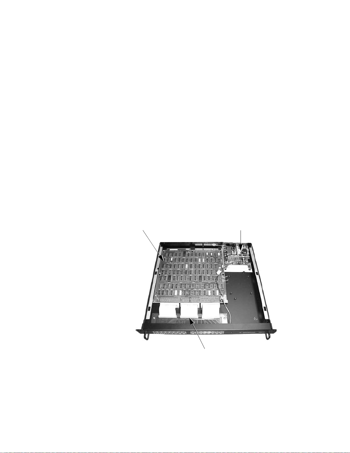
The ACC consists of three PC boards (refer to Figure 2-2):
•Main PCB
• Transition board assembly
• Power supply
Main PCB (78581-60200)
The Main PCB is considered the control/drive board. It connects up to 32
branch cables via the Transition Board to provide timed multiplexed
communication links and system synchronization. The circuitry on the
PCB sets up a polling cycle that allows each branch access to the SDN bus
in a sequential manner. Data coming in from one branch is received and
then “broadcast” simultaneously to the remaining branches of the SDN. As
each branch transmits in sequence, the SCC buffers, retimes, and
retransmits the data.
Theory of Operation
System communications is controlled, timed, and synchronized by the
ACC issuing regular system sync messages every 32 milliseconds and a
master sync message every second.
When power is supplied, the MODE switch is sensed for normal operation.
The ACC then issues a SYNC TAP message to all branches connected to
the ACC. The ACC senses the poll timer for 4 ms elapsed time to allow the
instruments to unload their receive buffers and load their transmit
buffers. Then, branch 0 is set up for a TALK TAP message by first sensing
the branch for activity and line state (polarity 1 or 0). If activity is sensed
within a 2.7 microsecond window, or the line is in the logic 1 state, then
the branch is considered faulty (FIRE AXE condition) and is skipped over
without a TALK TAP being issued. However, if no activity is sensed, a
TALK TAP message is transmitted out the branch in which the branch
number is embedded. The branch number is a 6-bit block encoded word
derived from the Block Code ROM. The 5-bit branch binary counter is the
ROM address pointer.
After the TALK TAP message has been transmitted, the ACC turns around
the line drivers and receivers and senses for activity from branch 0 and,
also, turns on the “broadcast” to all remaining branches. The ACC senses
for transmission activity for 12.2 microseconds and will timeout and
switch to the next branch if no activity is sensed. Activity is defined as one
or more positive transitions trapped within the 12.2 microsecond window.
The ACC senses the end-of-transmission by detecting 12.2 microseconds of
continuous silence; no positive transitions for example. The next branch in
sequence is then sensed for silence (no activity) and issued a TALK TAP
message in the same manner. Each branch is polled sequentially until all
32 branches have been issued a TALK TAP message. The last branch
2-13
Page 28
ACC Theory of Operation
polled at the end of 32 milliseconds must be branch 31 for TALK TAP
messages. If not, the poll cycle is in error and an error flag is set in the
next SYNC TAP message to indicate a POLL OVERLFOW; for example,
system overload or poll sync loss.
Transition Board (78581-61253)
This PCB interfaces from the RJ45 connector to the main PCB. There are
32 ports label from 0 through 31. Port 0 is the master time port for the
central stations. Ports 1 through 24 are bedside ports. Ports 25 through 31
are for other central stations, computers, or mainframes. The transition
board supplies the input/output data from the bedside to and from other
devices.
Power Supply (M2604-60002)
This is a 5V automatic switch power supply. It supplies power for the main
PCB, power on LED and the 5V indicator LED on the rear of the power
supply board.
Power SupplyMain PC Board
Transition Board
Figure 2-2. Internal Components of the ACC
2-14
Page 29

SDN and ACC System Level Troubleshooting
Section 3: SDN and ACC
System Level
Troubleshooting
Caution
Service and repair of the SDN system components is to be performed by
authorized service personnel only.
SDN Troubleshooting Overview
This section describes a logical approach for service personnel to diagnose
and identify the source of an SDN system problem and to isolate the
problem to the instrument/cable level for service and/or repair. The
troubleshooting procedures are presented simply and logically, and should
be followed in the sequence indicated.
The following troubleshooting procedures are written to minimize
disturbance to system patient monitoring and to avoid (and to determine
the need for) bringing down the entire SDN communications system.
When troubleshooting a new SDN system installation (not a patient
connected SDN system), it may be more expedient to power down the ACC
in order to checkout the cables and swap the Control/Driver PC board in
the ACC. Discretion must be applied according to the constraints of the
situation.
The content of this text presumes that the service person is familiar with
Agilent monitoring instrumentation and has a basic understanding of the
SDN system operation, specifically:
• SDN Architecture and Topology
• Agilent CareNet Controller
• Structure of System Cycle and Poll Cycle
•SDN Status
– Autopoll/SDN
– Offline/Online
–Local/Network
• SDN Interface Board — Functional Block Level
– Activity Detection, Autopoll Enable
– Priority Wires (Upstream/Downstream)
– Last Box Detection, Termination
3-1
Page 30

SDN Troubleshooting Overview
In addition, service personnel must be aware of the structure of the SDN
system being troubleshot with respect to:
The following abbreviations are used throughout this section:
•Care Units
•Bed Label/Branch Assignments
• IC Tuning
•IC/Branch Assignments
•BS — Bedside Monitor
• CS — Central Station
• LDC — Local Distribution Cable
• LDN — Local Distribution Network
• M/T — Monitor/Terminal; an SDN Bedside
• NT — Network Test
• IC — Information Center
• ACC — Agilent CareNet Controller
• SDC — System Distribution Cable
• XSDC — Extended System Distribution cable
• SDN — Serial Distribution Network
• SDNIF — SDN Interface
A simplified block diagram of the SDN system components is shown in the
following:
BS or CS
SDNIF
LDC
SDC
Wall Box
ACC
SDC LDC
Wall Box
Figure 3-1. SDN Components—Simplified Block Diagram
BS or CS
SDNIF
3-2
Page 31

SDN and ACC System Level Troubleshooting
Troubleshooting Resources, Tools, and Equipment
The following resources are available with the SDN instruments to
facilitate troubleshooting the SDN system:
•INOP Messages
•Overview Function
•Network Test
• Self-Test Routines
• Error Codes
• Instrument Service Manuals
A flat blade screwdriver and a 50-foot LDC are recommended when
troubleshooting the components of the SDN system.
яюэьыъщшчцхфущщтсрпьоцщнмулът
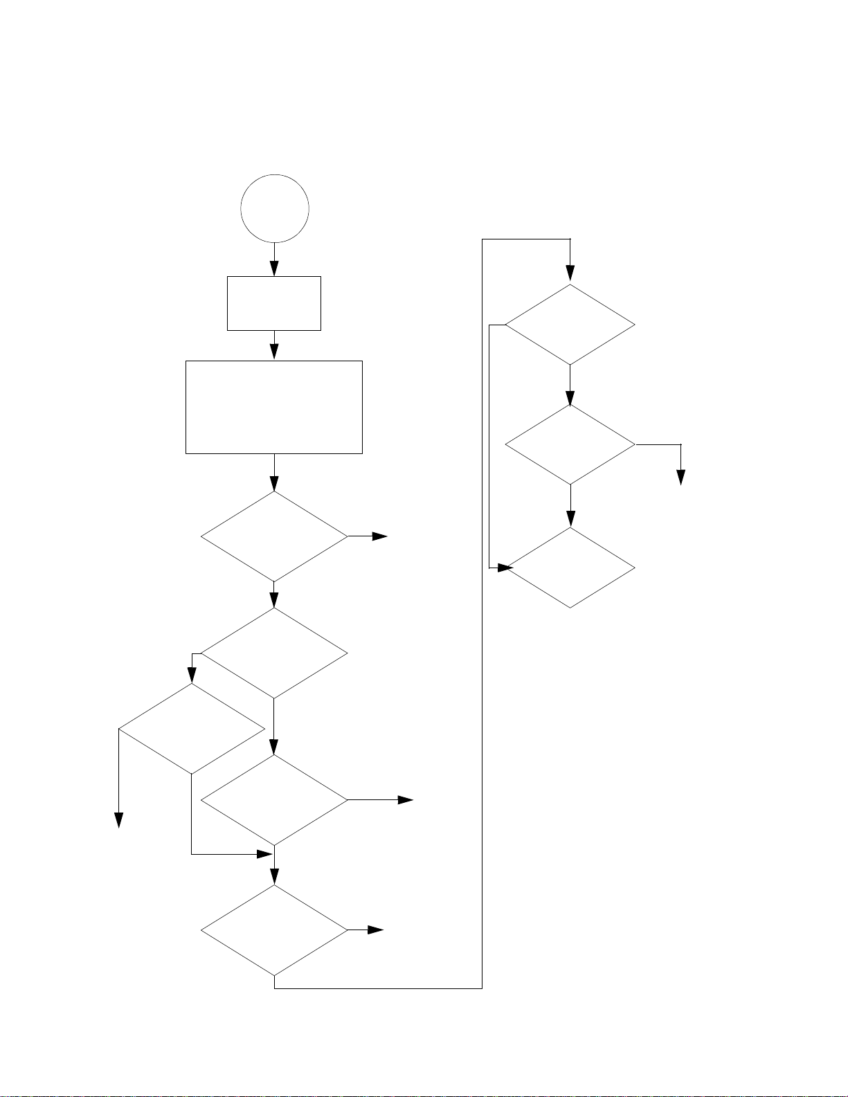
The SDN troubleshooting steps are outlined in a simplified SDN system
troubleshooting flowchart illustrated on page 3-4. Follow the steps
indicated in the sequence shown. Until you are familiar with the
troubleshooting flowchart procedure, refer to the detailed troubleshooting
procedures referenced for each step.
3-3
Page 32
Troubleshooting Resources, Tools, and Equipment
Figure 3-2. SDN System Troubleshooting Flowchart
Start
Step 1
Review system
configuration.
Step 2
Examine system.
1. Check if SDN is connected.
2. Network Test, Self-Test.
3. Error and INOP messages.
4. FIREAXE and overflow LEDs.
SDN
communication
problem (Receive,
Transmit).
Yes
FIRE AXE
LED
on?
Yes
No
Troubleshoot
instrument
Not
all
instrumentson the
instrumentsare on
the branch?
Isolate to one
instrument on
How many
branch are
affected?
How many
More
Step 5
branch.
All
than
one
ACC
Error
Troubleshoot
ACC
(and cable)
One
Troubleshoot
instrument
(and cable)
Troubleshoot
3-4
Look for Noisy
Nonoisy
branch
ACC
Branch
Found branch
No
Step 3
Evaluatebreadth
of problem.
Single Branch (SDN interface,
Step 4
Instrument
Self-Test
Multiple
branches
cable, or ACC)
Troubleshoot
Troubleshoot
ACC
instrument
(See
product’s
service
manual)
Page 33

SDN and ACC System Level Troubleshooting
яыььхсхньшфтщхъфьяфтхьщр спшълтсщр
Obtain a basic understanding of the customer’s system architecture and
topology, and familiarize yourself with the SDN configuration.
Review the instrument branch assignments, care unit definitions, and IC
tuning ranges. Pay particular attention to the configuration of bedsides: to
which IC they are hard-wired, and where they are being monitored.
Review the configuration of IC groups.
If the system configuration documentation is not available, use the branch
number assignment label located inside the ACC and the Network Test to
review the SDN system configuration.
STEP #2: Examine System and Gather Symptoms
An instrument using the SDN such as IC or bedside is more likely to be the
source of a problem than the SDN hardware such as the interconnecting
cables or the ACC. With this in mind, start by looking for the obvious
product malfunctions. To do this, use the resources available and evaluate
the results.
SDN Connections
SDN Error Messages
and Error Codes
SDN COMM FAILURE —
DUPLICATE BED
SDN COMM FAILURE —
ILLEGAL BED NUMBER
• Assure that the instrument is SDN connected.
• Examine INOP messages and error codes.
• Check FIRE AXE and OVERFLOW LEDs in the ACC.
Evaluate the results of the resources listed above to determine if there is
an SDN or non-SDN problem before continuing with this procedure.
The following messages can be found at the bedside, the central station, or
the telemetry mainframe.
Table 3-1: SDN Error Messages
SDN Error Messages Description
Indicates there is another bed on the system
using the same bed number as this bed. No
data is transmitted on SDN. Message appears
at top of screen.
Indicates this bed is not connected to a
branch in the range #1 through #24. No data
is transmitted on SDN. Message appears at the
top of the screen.
SDN EQUIP MALF Indicates disruption to SDN communication.
Problem may be in this instrument or in SDN.
3-5
Page 34

Troubleshooting Resources, Tools, and Equipment
Table 3-1: SDN Error Messages (Continued)
SDN Error Messages Description
NO OVERVIEW FUNCTIONS
AVAIL AB LE
NO DATA FROM BEDS IN UNIT In this Care Unit there are no beds in the
NO DATA FROM BED A bed which was currently being viewed in
Monitor/terminal is not connected to the
SDN, or it is getting no signals from the ACC;
i.e., it is operating in the Autopoll mode.
same group as this bed and no beds in the All
Beds Care group.
the OVERVIEW section of the screen has
stopped communicating on the SDN. The
message remains until the bed returns or
display is cleared with the CLEAR hard key or
until NEXTBED softkey is used to view
another bed.
Indicates discontinued or cut off data.
Displayed in sector(s) for which no data is
available—in inverse video. If the patient has
been moved or discharged, there are several
ways to clear this message.
Tune the sector to a different bed in the
system using SETUP and NEW BED keys. A
new bed label, waveform data, etc., will
appear if the new bed is active on the
network.
Diagnose the Problem
as SDN or
Non-SDN
Noisy Branch
3-6
NO RECORDER AVAILABLE This message appears when either stored
waveform or real time waveform recordings
are requested if IC recorder is out of paper or
its door is open (IC message CHECK PAPER/
DOOR RECORDER #_____ or NO RECORDER
ON LINE). This message appears for any
record request (stored, real time, or delayed)
if the M/T is in the Autopoll mode or if there
is no primary monitoring IC for this bedside.
Using the symptoms and information gathered in the previous steps,
diagnose and isolate the problem as a malfunction of a specific product or
a problem with the SDN system communication.
Some SDN and non-SDN product related symptoms are listed below.
1. Remove each RJ45 connector one at a time to determine which is the
noisy branch.
Page 35

SDN and ACC System Level Troubleshooting
2. Check the FIRE AXE LED to see if it is still lit and then replace the
RJ45 connector.
3. Check the next branch.
SDN and
Non-SDN Related
Problems
SDN Related Problems Non-SDN Related Problems
Instrument missing on
•
Network Test
Wrong status code for
•
instrument on Network
Test
SDN Error Codes:
•
0 - - - 8 - - - Monitor/
Terminal
5- - - D- - - IC
*If SDN error codes and non-SDN error codes occur, both subsystems must be
considered
Loss of data from one SDN
•
instrument to another
OVERFLOW or FIRE AXE
•
LED illuminated in the
ACC
Refer to the following table for SDN and non-SDN related problems.
Instrument not SDN connected
•
*Product error codes, but none of which
•
are
0 - - - 8 - - - Monitor/Terminal
5- - - D- - - IC
Loss of data at its source
•
Note
Action
• If a product malfunction has been clearly identified, then
troubleshoot that product (or non-SDN subsystem, such as an IC and
recorder) according to the troubleshooting procedures specified in
the associated product’s service manual.
It is highly recommended that the instrument(s) be disconnected from the
SDN during troubleshooting. SDN connections between ICs should be
disconnected when troubleshooting one IC in an IC group if the others are
remaining connected to the network.
• If the FIRE AXE LED in the ACC is illuminated or flickering, look for
a noisy branch. See “Cable Verification Procedures” on page 3-13.
• If SDN communication errors are indicated, and if no specific
product is immediately identified, then go to “STEP #3: Evaluate the
Breadth of the Problem” on page 3-8.
3-7
Page 36

Troubleshooting Resources, Tools, and Equipment
STEP #3: Evaluate the Breadth of the Problem
Decide whether this is a single branch problem or a multiple branch
problem. Find out how many branches are unable to communicate
properly on the SDN; how many branches are unable to receive data from
any other instrument and/or unable to transmit data to any other
instrument.
Test the reception of the bedside with the OVERVIEW mode or with the
NETWORKTEST. Test the reception of ICs under normal monitoring.
Test the transmission of the bedside with the NETWORK TEST at another
bedside or with the OVERVIEW mode at another bedside.
If multiple instruments were missing from the NETWORK TEST display
(STEP #2) or gave status codes other than 001 C normal operation or 0030
self-test, then a multiple branch problem is indicated.
Action
• If more than one branch cannot receive at all or transmit at all, then
troubleshoot the ACC. Refer to the ACC Troubleshooting section.
Other possible sources of multiple branch problems (lower
probability) are given on page 3-12.
• If only 1 branch cannot receive at all or transmit at all, then go to
STEP #4.
Other possible sources of single branch problems (lower probability)
are given on page 3-12.
STEP #4: Self-Test Check of SDN Interface Circuitry
The problem has now been isolated to a system communication problem
on one branch. The problem could reside in the SDN interface board, SDN
cabling, or branch specific circuitry in the ACC. Refer to Figure 3-3.
Note
The SDN interface residing in the bedside/mainframe or IC is more likely to
be the cause of the problem than the branch specific circuitry in the ACC.
Each instrument’s self-test routine checks a portion of its own SDN interface
circuitry (SIC chip, buffer RAM, signature RAM).
3-8
Page 37

SDN and ACC System Level Troubleshooting
Possible Source of Problem
M/T or IC
Wall Box
SDN
Interface
Figure 3-3. SDN Interface Problem Area
If not already done, run the instrument’s self-test on each SDN instrument
on the faulty branch.
Refer to instrument’s service manual for details. Some codes identify
faulty instrument circuitry.
If an instrument malfunction is indicated, troubleshoot that product’s SDN
interface according to the instructions described in the associated
product’s service manual.
Branch Specific Circuitry
in the ACC
ACC
M/T or IC
SDN
Interface
Figure 3-4. SDN Instrument Malfunction
If no specific instrument malfunction is indicated, refer to the following
figure:
Wall Box
ACC
3-9
Page 38

Troubleshooting Resources, Tools, and Equipment
M/T or IC
Wall Box
SDN
Interface
Figure 3-5. SDN Non-Instrument Malfunction
• If the problem affects only one instrument or all the instruments on
the branch, go to STEP #5.
• If the problem does not affect all instruments on the branch, it can
be concluded that the ACC and cabling running up to, but not
including the last “good” instrument, are functioning properly. Go to
STEP #5.
The problem is located in one of the following places:
a. SDN Interface PC Board (drivers, receivers and relays and other
circuitry were not tested in instrument’s self-test routine).
ACC
Caution
b. ACC (components which are branch-specific)
c. Cables/Connectors (LDC, wall box, SDC, connection to ACC)
In order to verify which part of the branch is faulty, it is now necessary to
swap the branch with a known good branch:
At ACC, disconnect RJ45 connectors and jump wires to an unused branch.
CAUTION — Ability to view swapped monitor/terminal:
• If the “unused branch” is not in the same Unit (e.g., same ICU) as the
former branch, then it cannot be viewed in OVERVIEW mode.
Unused bedside branches will be in Care Unit 1 if default values
were programmed in the IC(s) at installation.
• If the “unused branch” is outside the tuning range of the IC, then it
cannot be viewed at that IC.
3-10
Page 39

SDN and ACC System Level Troubleshooting
Warning
Caution
Caution
Warning — Reconnection Warning — Disconnect SDN patient before
swapping:
Disconnect the patient from the monitor/terminal before swapping
branches in the ACC.
EXTEND TEST mode can be used to generate waveforms for
verification.
CAUTION — Disconnection Caution — Data will be missed:
• While a monitor/terminal is disconnected, no alarms are available
from that monitor/terminal at the IC or at any other monitor/
terminal in the OVERVIEW mode.
• While an IC is disconnected, it generates no alarms or alarm
recordings.
CAUTION — Use Appropriate Unused Branch Number:
• For a monitor/terminal, the “unused branch” must be branch #1
through #24. Make sure that the “unused branch” does not have a
telemetry bedside assigned to it.
If a monitor/terminal is placed on branches #0 or #25 through #31,
the message “SDN COMMUNICATION ERROR — ILLEGAL BED
NUMBER” will be displayed. The bedside will be able to receive data,
but will not be able to transmit data.
• For an IC, the “unused branch” must be branch #0 or #25 through
#31.
Make sure that the “unused branch” does not have a telemetry
bedside assigned to it.
STEP #5: Isolating a Problem on A Local Distribution Network (LDN) With Two or More Instruments
The problem has been isolated to one of the SDN interface boards, or to
one of the LDC or system distribution cables (SDC or XSDC).
A problem on the LDN might affect any number of instruments on the
branch.
A problem in one SDN interface might affect other instruments on that
branch without impairing its own function on the SDN.
3-11
Page 40

Troubleshooting Resources, Tools, and Equipment
Miscellaneous Items
The preceding troubleshooting procedures provide a general methodology
which captures the majority of electronic hardware failures. However,
several problems can be identified which will not be caught, and are
elaborated below.
a. Cable checking was not always explicitly stated as a possible problem
source. However, cables should be checked for continuity and shorts
when suspect using the cable verification procedure specified on page
3-13.
Cable intermittents: Moving cables with intermittent connections can
cause symptoms to disappear or reappear unpredictably.
b. Excessive noise on one branch can impair communications on all
branches. This can occur if a raw cable with no wall box connector is
wired to the ACC and the raw ends are shorting to each other or to
conduit. This can also occur if the wall box connections are loose or
LDCs are loosely connected. The FIRE AXE LED will usually be
illuminated. Instruments may disappear and reappear on the Network
Test, or their status may change from 001 C. Noisy branches can be
identified by low voltage levels below ground and high levels above 5V.
Proceed with cable verification procedure specified on page 3-13.
c. Hospital ground may not meet the system specification. If this is
suspected, refer to the ground check procedure on page 3-13.
d. The hospital has installed cables (other than Agilent Technologies SDN
or Agilent Technologies Analog cables) in violation of Agilent
Technologies distance and shielding specifications. The new cables are
causing interference.
e. Overloaded system — Constant or intermittent overflow: In an
overloaded system some branch will be transmitting at the end of the
32 ms poll cycle. All higher numbered branches get no chance to
transmit. The OVERFLOW LED will be illuminated or flickering in the
ACC. True chronic overflow is highly improbable with the current set
of products in a fully loaded system (24 monitor/terminals, 6 ICs, and
PDMS).
Recap of Troubleshooting Procedures:
STEP #1: Review System Architecture
STEP #2: Examine System — gather symptoms
• Determine if the problem involves SDN connected equipment
• Error codes and INOPs
3-12
• ACC LEDs
Page 41

STEP #3: Run Network Test: Evaluate breadth of problem (more than one
branch = ACC problem)
STEP #4: One branch: run instrument self-test to check SDN interface and
isolate to ACC or local distribution network
STEP #5: Isolate to one instrument on Local Distribution Network
Reverification Instructions
Three forms of communication should be verified: reception, transmission,
and interactive protocol.
a. Reception.
b. Transmission.
SDN and ACC System Level Troubleshooting
To verify the monitor in a care unit with other beds, put it in a Care
Group with them and view beds in OVERVIEW mode. Show the bed
roster to verify the new bed label corresponding with the current
branch.
Cable Verification
Procedures
Run the Network Test on an (unswapped) monitor/terminal. The
Network Test determines whether instruments in the swapped
configuration are active on the SDN and are able to transmit the proper
instrument status message. The Network Test shows all instruments on
the system except the instrument displaying the test, regardless of Care
Unit definition or IC tuning limits.
To verify the monitor/terminal: View this bed at another monitor/
terminal or at an IC.
To verify an IC: View hard-wired telemetry bedside monitors on a
monitor/terminal in the OVERVIEW mode or view the Network Test on
a monitor/terminal.
c. Interactive Protocol.
To verify the monitor/terminal: Request a real time recording from the
monitor/terminal to the IC.
To verify the IC: Request a real time recording from any bedside
connected to that IC.
Cable check procedures are appropriate in the following situations:
• New system installation cable verification
• Upgrades to existing SDN system involving new branches
• SDN Troubleshooting
• When a cable is suspected to be faulty
• When the FIRE AXE LED is illuminated in ACC
• Reverification after repair of cable problem
3-13
Page 42

Troubleshooting Resources, Tools, and Equipment
These procedures address the following problems:
•Hardware problems
• Shorts in data wires and priority wires
• Opens in data wires and priority wires
•Miswiring
•Voltage levels (ACC drivers)
• Cable identification
•Ground checking
Hardware Problems
Verify Instrument End
of the Branch Cable
The cable verification procedures for hardware problems are separated
into two steps.
The first step is performed at the ACC end of the branch and is used to
verify the functional operation of the ACC drivers and the absence of
shorts in the data wires.
The second step is performed at the SDN instrument end of the branch (IC
or monitor/terminal) and identifies opens in the data wires and verifies
proper operation of priority wires. Miswiring of blue and pink data wires
is evident. This procedure is valid whether or not instruments are
connected to the branches. Refer to the following section.
Check for opens between the ACC and instrument
a. Disconnect the local distribution cable (LDC) from the wall box
connector and from the instrument.
Using a digital multimeter, check the LDC for continuity, opens and
shorts.
b. If no problem is found with the LDC, power down the ACC—see page 4-
1.
c. Measure the resistance of the system distribution cable at the
instrument end as follows. Refer to connector pin illustrations shown
in Figure 3-6.
3-14
PIN A(+) — — to — — PIN E(–) = 120 Ohms (+11 Ohms; - 5 Ohms)
PIN A(±) — — to — — PIN D (GND) =
PIN E(-) — — to — — PIN D (GND) = ∞
∞
Page 43

SDN and ACC System Level Troubleshooting
Verify Proper Operation
of Priority Wires
SDN Bedside:
With the ACC running and the instruments connected to the branch,
measure the priority wire voltage from the downstream connector on the
last instrument—most downstream instrument—on the branch as indicated
on the following connector pins. Refer to the connector pin illustrations
shown in Figure 3-6.
MEASUREMENT NOMINAL VOLTAGE
MEASURED WITH DVM
PIN C (±)——to——PIN B (–) = ≥3.0V
PIN C (±)——to——PIN D (GND) = ≥0.6V
PIN B (–)——to——PIN D (GND) = ≥3.6V
PIN C (+)——to——PIN A or PIN E =
PIN B (–)——to——PIN A or PIN E = ∞
PIN A (±) ----------------> DATA WIRE — PINK (positive)
PIN B (–) ----------------> PRIORITY WIRE — BLACK (negative)
PIN C (+) ----------------> PRIORITY WIRE — GRAY (positive)
∞
PIN D (GND) ----------------> DRAIN WIRES — GROUND
PIN E (–) ----------------> DATA WIRE — BLUE (negative)
3-15
Page 44

Troubleshooting Resources, Tools, and Equipment
78534A Moni tor/Terminal
Downstream Con ne ctor (gray)
Pin B (–)
Priority Wire—Black
(negative)
Pin C (+)
Priority Wire—Gray
(positive)
Pin A (+)
Data Wire—Pink
(positive)
Pin E (–)
Data Wire—Blue
(negative)
Pin D (GND)
Drain Wires—Ground
3-16
Ground Check
Procedure
Figure 3-6. SDN Downstream Connector Gray
The maximum ground potential difference between the third wire ground
delivered to an ACC and the third wire ground delivered to any of its SDN
instruments, with the SDN cables disconnected, is 500 mV RMS.
The following check will usually indicate if a grounding problem exists on
a given branch without taking the whole system down.
a. At the end of the branch cable in question turn off and unplug the
instruments using that branch.
b. Measure the voltage between the ground coming through the SDN wall
box and the third wire ground of each instrument’s wall outlet. The
value measured on an voltmeter must not exceed 500 mV RMS.
Page 45

ACC Maintenance
ACC Maintenance
Section 4: ACC Maintenance
The Agilent CareNet Controller (ACC) is a ROM-driven microprogrammed
state machine self-contained on the Control/Driver PC board for ease of
serviceability.
Once installed and running properly, the ACC requires virtually no
periodic maintenance or servicing. However, when an electrical problem is
evident within the ACC, isolation of the problem and repair can be
accomplished using the troubleshooting procedures and self-test routines
listed in Section 3: SDN and ACC System Level Troubleshooting.
Caution
Ground wrist strap must be worn and grounded to the ACC chassis.
ACC Failure, Power Up, and Power Down Procedures
When the ACC has to be powered down for service or during a power
failure, the system communications is interrupted. If any of the branches
have more than one instrument daisy-chained on that branch, the local
distribution network (LDN) takes over and allows the daisy-chained
instruments to communicate with each other in the autopoll mode. When
power is cut off to the ACC, the following occurs to the instruments
connected to the SDN branches:
Bedside Nothing perceptible happens. The monitor goes into the autopoll mode
automatically, but nothing happens to the wave forms. When attempting
to enter the OVERVIEW mode or OVERVIEW SETUP mode, the monitor
displays the message NO OVERVIEW FUNCTION AVAILABLE. When
power is restored to the ACC, the bedside display blanks for a couple of
seconds, and then resumes SDN communications.
Information Center (IC) All sectors will display “No Data From Bed.”
When power is restored to the ACC, the SDN bedsides that were blanked
now reappear at the IC.
4-1
Page 46

ACC Maintenance
4-2
Page 47

Part Numbers
Parts List
Section 5: Part s List
Wall Box
Minimum Depth =
2-3/4 in.
Figure 5-1. SDN Faceplate/Connector Kits-Component Locations (78599AI-J01, JO2, and J53)
Single Gang
78581-00150
Figure 5-2. SDN Faceplates, Single- or Dual-Gang
Dual Gang
78581-00160
5-1
Page 48
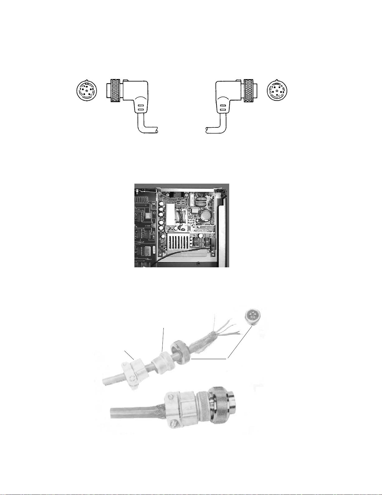
Part Numbers
Jade
Gray
Cocoa
Brown
3 ft. 78599AI-J03
(8120-3591)
6 ft. 78599AI-J06
Figure 5-3. Standard Length Local Distribution Cables (LDC)
Figure 5-4. Power Supply Assembly (M2604-60002)
Solid
Backshell
Cable
Clamp
Upstream
Male Plug
Connector
Figure 5-5. Variable Length LDC Kit (78599A-J50)
5-2
Page 49

LDC Cable Not
Included in Kit
Cable
Clamp
Solid
Backshell
Parts List
Upstream
Male Plug
Connector
Order Cable
Separately
AS 78599AI-J54
Filler
Strips
Blue
Wire
Downstream
Male Plug
Connector
Figure 5-6. Connector LDC Kit (78599AI-J52)
Pink
Wire
Braided
Shield
SDC or SXDC
Drain
Wire
Foil
Figure 5-7. SDC and XSDC System Distribution Cables
5-3
Page 50

Part Numbers
RJ45
Connector
SDC or SXDC
Option J03 (78581-60350)
Drain
Wire
Connector Components
Included in J52 Kit
M3199AI
Blue
Wire
Pink
Wire
Braided
Shield
Figure 5-8. SDC and XSDC System Distribution Cables with
M3199AI Option J03 for Runs Longer than Allowed with UTP Cable
Part Number Description
78581-68200 Main PCB
78581-61253 Transition board assembly
M2604-60002 Power supply
78581-61257 Wall mount
78581-61080 Second ground wire
78581-61251 Cover assembly
78581-61250 Chassis assembly
78581-61256 LED cable assembly
78581-60350 RJ45 to SDN cable
78581-61254 Transition board cable
78581-61255 Power cable assembly
2110-0454 Pico fuse, 7A (Main PCB)
5-4
Page 51

Overview
Component Installation and Disassembly Procedures
Section 6: Component
Installation and Disassembly
Procedures
The Serial Distribution Network (SDN) consists of an Agilent CareNet
Controller (ACC) with up to 32 signal distribution cables (branch cables)
emanating from it to each wall box, the connectors, switch wall boxes, and
local distribution cables that interconnect the wall box to the instruments.
The essential parts used to interconnect the SDN system components are
illustrated in Figure 6-1 on page 6-2. See “Parts List” on page 5-1 for a
complete listing of SDN and ACC parts, and specifications.
Caution
Cables and parts supplied by Agilent Technologies, Inc. must be used in
the installation of the SDN system, or the warranty may be void.
This installation section describes the site preparation and installation
responsibilities as well as the detailed installation instructions for
installing the parts of the SDN. An overview of the SDN and ACC
installation, system communication verification procedures, and the
recommended installation sequence to follow is given on page 7-8.
Within certain limitations, various combinations of bedside monitors and
central station displays may be connected to the SDN via branch cables.
The instruments connected to the SDN are ordered separately from the
SDN components. The installation requirements for these instruments are
outlined in detail in separate documents. Refer to the associated
instrument’s service manual.
Typical SDN System Interconnecting Parts
Examples of typical SDN system configurations are illustrated at the
beginning of this document. Although the number of branch cables and the
types of instruments used may vary per the installation, the component
parts used to interconnect the SDN system are illustrated in Figure 6-1.
See “Parts List” on page 5-1 for a complete listing of SDN and ACC parts,
options, and installation kits.
6-1
Page 52

Installation Responsibilities—Customer and Agilent Technologies
110 Edge
Connector
ACC
Wall Box
(USA)
Wall Box
(European)
Branch
Cables
Monitor
Connected
with LDC
Figure 6-1. Component Parts of a Typical SDN System
Installation Responsibilities—C ustomer and Agilent Technologies
The site preparation installation responsibilities for installing the
component parts of the SDN are outlined below. Specific details of Agilent
Technologies Customer Engineer’s (CE’s) responsibilities for installation
and verification are given in this section.
Refer to the Site Preparation Check Lists shown on page 7-1 to ensure
proper timing of’ installation requirements and materials.
Customer Installation Responsibilities
• Determine the SDN system configuration (assisted by Agilent
Technologies sales/service personnel).
• Order the Agilent CareNet Controller (ACC), LDCs, LDC connector
kits and faceplates, installation options, and other instruments.
• Choose the installation sites for the ACC and connecting system
instruments.
6-2
Page 53

Component Installation and Disassembly Procedures
• Measure each length of branch cable and order the appropriate
branch cable spools. Refer to page 8-11 for spool sizes and related
part numbers. Consider service loops — order 10% longer cable
lengths. NO SPLICING — BRANCH CABLE RUNS MUST BE
CONTINUOUS.
• Prepare the sites:
– Ensure sites conform to environmental specifications.
– Install AC power receptacles within 1.8 m (6 ft.) of instruments
connected to the SDN, and install AC power receptacles within
1.5 m (5 ft.) of the ACC.
– Install wall mounts, consoles, etc. for mounting monitoring and
display instruments.
• Supply and install branch cable enclosures (conduit, troughs,
raceways, etc.) when necessary.
• Supply and install NEMA switch wall boxes near each instrument (2
3/4-inch depth minimum with conduit knockouts).
• Receive and store equipment and instruments.
• Install and test UTP cable using Category 5 rules with AMP 110 edge
connectors.
• Supply a standard 19" telecommunications rack or:
• Mount a plywood panel 40.6 cm wide x 50.8 cm high x 1.9 cm deep,
minimum (16 in. W x 20 in. H x 3/4 in. D) to wall surface at the
chosen ACC site location. DO NOT MOUNT ACC TO WALL
SURFACE.
• Install branch cables from plywood panel (ACC site location) to the
switch wall boxes. Leave at least a 4-foot service loop at the plywood
panel (ACC).
• Supply certification of Category 5 UTP installation to Agilent
installer.
• Ensure cable installation conforms to local building codes.
• Schedule Agilent Technologies service personnel to interconnect
parts and instruments of the SDN.
• Schedule key operator training for SDN system operation.
Agilent Installation Responsibilities
• Assist customer in planning system configuration.
• Inspect each instrument site for conformance to environmental
specifications and service access requirements.
• Supply system distribution branch cables, connectors, and
faceplates.
• Mount the ACC to the plywood panel or rack mount.
• Connect branch cables to each wall box.
• Connect branch cables to the ACC.
• Install the instruments.
• Connect the instruments to the SDN.
• Perform comprehensive system verification procedures.
• Train key operators to ensure proper SDN system operation.
6-3
Page 54

Installation Responsibilities—Customer and Agilent Technologies
6-4
Page 55

Introduction
Site Preparation/Installation Checklists
Section 7: Site Preparation/
Installation Checklists
The following pages contain the checklists for site preparation and
installation.
7-1
Page 56

Introduction
Agilent Technologies Representative Checklist
Prior to Installation
(New Hospital Building)
___ Conference with hospital personnel.
___ Conference with hospital architect.
___ Establish type of patient monitors at bedside and remote
areas.
___ Establish Information Center customization (alarms, scales,
and recording parameters, for example).
___ Review the definition of Care Units, bed labels, and tuning
ranges with hospital personnel.
___ Architect aware of number of conduit runs required.
___ Architect aware of recommended conduit size. Refer to
Table 8-1 on page 8-10.
___ Architect aware that no other wires should be run in the
same conduit with signal cables.
___ Architect aware that AC power, diathermy cables, and so on
should be run far enough away from site to prevent
interference—at least 0.3 m (1 ft.) away.
___ Architect aware that Agilent Technologies recommends
NEMA conduit switch wall boxes with a minimum depth of 7
cm (2 3/4 in.) with conduit knockouts (such as RACO 560 or
562).
___ Architect aware that builder must supply and install Bedside
and Information Center wall boxes.
___ Architect given dimension of the SDN Agilent CareNet
Controller (ACC).
___ Architect aware that plywood panel must be mounted at the
ACC site location 40.6 cm high x 50.8 cm wide x 1.9 cm deep
(16 in. H x 20 in. W x 3/4 in. D) minimum for wall mounting.
If rack mounting, architect aware that 19"
telecommunications rack supplied.
___ Architect aware that Agilent Technologies supplies bedside
and Information Center switch wall box faceplates with LDC
connector kits.
___ Architect aware that Agilent Technologies supplies SDN
Agilent CareNet Controller (ACC) which is to be installed by
Agilent Technologies service personnel.
7-2
___ Architect aware that Agilent Technologies will supply
instrument wall mounts which are to be installed by the
builder.
Page 57

Site Preparation/Installation Checklists
___ Architect aware that individual 3-wire AC outlets are
recommended for each beside instrument, each Information
Center, computer, and the ACC.
___ Cables have been identified by bed number or remote site
number and ordered after cable length from point-to-point
has been carefully measured by the hospital. Order at least
10% longer overrun to prevent a cable too short to do the job.
Refer to “Install Branch Cables” on page 8-11 for cable
ordering information, and order the associated spools to
accommodate branch cable run requirements.
NO SPLICING—CONTINUOUS CABLE RUNS ONLY.
___ Architect aware that the builder must install cables (and
cable enclosures when necessary).
___ Confirmed day scheduled for patient monitoring equipment
installation with hospital personnel assigned.
___ The “clerk of works” has a move-in day assigned for the
equipment.
Note
Go over checklist and correspondence again; it will be worth the effort!
Oversights will cause delays; delays often run costs up exponentially.
7-3
Page 58

Introduction
Agilent Technologies Representative Checklist
Prior to Installation
(Established Hospital Building)
___ Conference with Superintendent.
___ Establish site locations in building.
___ Establish number of bedside units and review the definitions
of Care Units, bed labels, tuning ranges.
___ Establish type of patient monitors at bedside and remote
areas.
___ Establish type of Information Center customization (alarms,
scales, and recording parameters, for example).
___ Plant engineer (or electrician)/architect aware of the number
of conduit runs.
___ Plant engineer/architect aware that he should call for
recommended conduit for all cable runs, that installation is
the responsibility of the hospital. Refer to table Table 8-1 on
page 8-10.
___ Plant engineer aware that hospital is responsible for
supplying and installing wall boxes—NEMA conduit switch
wall boxes with a minimum depth of 7cm (2 3/4 in.) with
conduit knockouts (such as RACO 560 or 562).
___ Outline dimensions and specifications given to plant
engineer/architect of recommended NEMA bedside switch
wall boxes (such as RACO 560 or 562).
___ Plant engineer/electrician aware that cable pulling is the
responsibility of the hospital and “pull boxes” are required
(local electrical code) at recommended intervals based on
number of conduit bends and cable length.
___ Plant engineer/electrician/architect aware that no other
wires should be run in the same conduit with signal cables.
___ Plant engineer aware that installation of Agilent Technologies
supplied wall mounts is the responsibility of the hospital.
___ Plant engineer/electrician/architect aware that AC power
diathermy cables, and so on should be run far enough away
from site to prevent interference—at least 0.3 m (1 ft.) away.
___ Plant engineer given dimension of the SDN Agilent CareNet
Controller (ACC).
___ Plant engineer aware that plywood panel must be mounted at
the ACC site location 40.6 cm high x 50.8 cm wide x 1.9 cm
deep (16 in. H x 20 in. W x 3/4 in. D) minimum, if unit is wall
mounted. If rack mounting, aware that 19"
telecommunications rack must be mounted.
7-4
Page 59

Site Preparation/Installation Checklists
___ Plant engineer aware that LAN cable must be Cat. 5,
installed, and certified.
___ Plant engineer/electrician aware of the number and location
of AC power 3-wire (one ground wire) outlets.
Note
Note
Each IC requires two AC outlets and each recorder or hard copier requires
one AC outlet.
___ Point-to-point cable length measurements according to bed
numbers have been received. Order at least 10% overrun to
prevent getting a cable too short to do the job.
NO SPLICING—CONTINUOUS CABLE RUNS ONLY.
___ Confirmed move-in date with administrator and electrician.
___ Confirmed move-in date with head nurse so that patients in
wing will be assured minimum discomfort while the
installation is being made.
___ The “clerk of the works” has a move-in day assigned for the
equipment.
Go over the check list and correspondence again; it will be worth the effort!
Oversights will cause delays; delays often run cost up exponentially.
7-5
Page 60

Introduction
Architect Checklist
Prior to Installation
___ Builder knows the number, size, and location of conduit runs.
___ Builder knows the number, location, and voltage of AC power
outlets.
___ Builder knows location and number of each type of system
outlet box.
___ Builder/electrician aware that he must install switch wall
boxes (and conduit when necessary).
___ Builder and electrician aware that only patient monitor
signal cables can be run in conduit and that AC power,
diathermy cables, and so on, should be run far enough away
to prevent interference—at least 0.3 m (1 ft.) away.
___ Builder aware that Agilent Technologies requires NEMA
conduit switch wall boxes at each bedside station, remote
station, and possibly at the Patient Information Center.
___ Builder aware that Agilent Technologies will supply
faceplates for standard NEMA switch wall boxes.
___ Builder aware that Agilent Technologies will supply SDN
Agilent CareNet Controller (ACC).
___ Builder aware that Agilent Technologies may supply SDN or
LAN cables.
___ Builder aware of mounting requirements of brackets and
shelves if these are to be used.
7-6
Page 61

Building
___ Route from receiving dock to system site can accommodate
Area Layout
___ Floor plan has been established and permits access to
___ Storage area is available for manuals, accessories, and
Environment
___ Floor can support equipment.
___ Ventilation or air conditioning maintains ambient
Site Preparation/Installation Checklists
Hospital Representative Checklist
Prior to Installation
equipment (ceilings, stairways, corridors, elevators, and so
on).
equipment for service and operation.
consumables. Contact your local Agilent representative for
space requirements.
temperature between 5° C and 30° C (41° F and 86° F) at
less than 80% relative humidity.
Electrical Power
___ Power distribution type has been established and proper
receptacles provided. Proper hospital grade connector has
been selected and Agilent representative notified of selection.
___ Grounding precautions have been taken.
___ A separate circuit, capable of handling present and future
loads, has been installed.
Miscellaneous
___ Review definition of Care Units, bed labels, and tuning
ranges with hospital personnel.
___ Variable length cables have been measured and specified
with related labels.
___ Conduit and outlet box installation has been planned and
completed.
___ Sufficient consumables have been ordered.
___ Bedside station, remote area, and Patient Information Center
instrument mounts have been planned/installed.
___ Plywood panel has been installed at the ACC site location, if
mounting unit on the wall or access to 19”
telecommunications rack if rack mounting unit.
___ Operator training for medical personnel has been scheduled.
7-7
Page 62

Verification Procedures
Verification Procedures
Overview of SDN/ACC Installation and System Communication Verification Procedures
The following overview depicts the recommended order of on-site
customer engineering activities during SDN/ACC component installation.
Refer to the associated section as indicated to perform the detailed
installation procedures and follow the SDN/ACC installation procedures
in the sequence indicated.
1. Planning and configuration review
2. Standalone instrument verification and installation
3. SDN wiring installation
4. Instrument connection to the SDN
5. System communication verification
6. Simple practical checks
Planning and Configuration Review
Make sure all instruments and SDN components of the SDN
communication system have been received and delivered to the
appropriate installation site.
Review SDN system configuration.
Standal one Instrument Veri fication and Installation
Unpack the instruments at their installation location. Follow the detailed
unpacking instructions supplied with each instrument.
It is recommended that proper operation of the instrument be verified
prior to mounting. Use the performance verification procedures listed in
each product’s service manual, including any self-test procedures, to
properly verify the functional operation of the instrument.
Refer to “SDN Error Messages and Error Codes” on page 3-5 for a listing of
SDN fault messages for instruments not connected to the SDN.
Unpack the ACC and mount it to a 19” rack. Optionally, wall mount it to
the installed plywood panel (refer to “ACC Wall Mounting Procedures and
Power Installation” on page 8-8). Verify the functional operation of the
ACC by plugging it in and checking the LEDs.
7-8
Page 63

SDN Installation
SDN Wiring Installation
UTP, SDC, or XSDC cables should be continuous from the location of the
ACC to the wallbox. Refer to pages 8-11 through 8-16 for more
information.
Instrument Connection to the SDN
Connect the instruments to their associated wall boxes using LDC cables.
Plug in any ACC terminated LDCs to the upstream connector in the IC.
Daisy-chain ICs which are to share one branch. Turn on power to the
instruments. Ensure that each SDN bedside instrument is in Demo Mode.
Installation
Section 8: Installation
System Communication Verification
Verify the tuning range of each IC. Tune in SDN bedsides at IC. This
checks the SDN broadcast function of those bedsides and the SDN receive
function of the IC. Refer to the detailed procedures given in the IC
documentation.
Ensure that each SDN bedside instrument is in Demo Mode.
If instruments are missing, note their branch numbers and refer to “SDN
and ACC System Level Troubleshooting” on page 3-1.
Practical Checks
At each SDN bedside, verify that the UNIT ROSTER and BED LABEL
correspond with what the hospital staff wants at that location. Errors
indicate mistakes in wiring to the correct branch or mistakes in IC
programming.
Enter OVERVIEW mode for each bedside and verify the SDN receive
communication function of each SDN bedside. Step through several beds
using the NEXT BED softkey. Notice the bed label change. Press the
CLEAR hardkey.
While at each SDN bedside, request a REAL TIME recording and verify the
interactive SDN communication between bedsides and ICs. Press REAL
TIME softkey, select a waveform to be recorded (softkey), look for message
8-1
Page 64

SDN Installation
“CONTINUOUS RECORDING” at top of screen, wait about five seconds and
press the STOP softkey.
Reset each IC and verify that there are no error codes. Examine the
recorder strip to verify that ICs sharing the same recorder(s) are all on the
same SDN branch. Verify that each IC has a unique Box No. (0-3) and IC
I.D. No. (1-6).
Test and Inspection Procedures
The following test and inspection procedures are done by an Agilentqualified service provider at the time of installation or repair.
Test Block
Name
Visual:
ower On:
P
erformance:
P
Test or Inspection to Perform
For installation, perform visual inspection of shipping
case and contents. All other cases inspect installed
device.
1. Power on device.
2. Examine all LED’s on the main PCB for normal
operation. The following is “normal operation”
• LED condition
DS6 Solid Red On
DS5 Solid Green On
DS1 Fast Flicker Red On
DS2 Off (Red)
DS3 Off (Red)
DS4 Solid Red On
DS8 Off (Yellow)
DS7 Off (Yellow)
Refer to Figure 8-1.
Examine the green LED on the front of the unit and the
LED on the power supply on the rear of the unit.
Are all LEDs indicating normal operation?
1. Verify correct cable to branch location by turning on
the bedside monitor and checking for proper branch
numbering.
2. Perform operational checkout. Scroll through all
connected beds in Overview, or tune in all
connected beds into the central station.
Does the system pass the performance checkout?
Expected Test
Results
No visible damage V:P or V:F
Expected answer
is “Yes”
Expected answer
is “Yes”
What to Record on
Service Record
Where P=Pass and F=Fail
PO:P or PO:F
Where P=Pass and F=Fail
P:P or P:F
Where P=Pass and F=Fail
8-2
Page 65

Installation
Test Block
Name
Test or Inspection to Perform
Figure 8-1. Main PCB Board LED Locations
DS6
DS1 DS2 DS4DS3 DS8 DS7
Expected Test
Results
What to Record on
Service Record
DS5
Safety:
1. Has the secondary ground wire been attached to the
78581B? If “No” proceed to step 2
2. Attach secondary ground if missing or visually
inspect ground connections at both ends of the
attached secondary ground, then proceed to step 3.
3. Confirm that all locations for all connected
branches are at the same ground potential.
Procedure: Measure the voltage between the ground
coming through the SDN wall box and the third wire
ground of each instrument’s wall outlet (power outlet).
The value should be less than or equal to 0.5V RMS.
-OR-
Perform Safety (1) test on all the connected devices.
• If “yes”, done and record S: P.
• If “no”, proceed to step 4.
4. Look at all bedsides for either an attached
secondary ground wire or a M1965A potential
separator connected to each bed where the voltage
was greater than 0.5V RMS.
• If “yes”, done and record S: P.
• If “no”, proceed to step 5.
5. Install secondary ground wire to bedside for any
connection where the ground potential was greater
than 0.5 V RMS.
Done and record S: P.
Expected answer
is passed
S:P or S:F
Where P=Pass and
F=Fail.
8-3
Page 66

SDN Installation
When to Perform
SERVICE EVENT Test Blocks Required
Installation
Repair
Main PCB
Power Supply
Perform Visual, Power On, Performance, and Safety Test
Blocks
Perform Power On, and Performance Test Blocks.
Perform Power On, Performance, and Safety Test Blocks.
Upgrades
Add additional branch
terminations
All other Service Events Perform Power On, Performance, and Safety Test Blocks.
Installation Tools, Materials, and Equipment
The recommended installation tools, materials and equipment that are
required to properly install the components of the Serial Distribution
Network are listed below.
•Screwdrivers:
–Posidrive #2
– Flathead, medium blade, 8-inch shaft
• Insulation stripping tool:
– Ideal Industries, Sycamore, Ill.
– Catalog No. 45-128 (or equivalent)
• Heat gun (for heat shrink tubing)
• Wire strippers, for 20 and 16 gauge wire
• Hand drill or power screwdriver
Perform Power On, Performance, and Safety Test Blocks for
each additional branch.
SDN Installation Restrictions and Limitations
The ACC can accommodate up to 32 separate branch cables emanating
from it to the wall boxes (instruments) connected to the SDN. Various
combinations of patient monitors and patient information center displays
may be connected to the SDN providing the system is configured within
the restrictions and limitations listed here.
• Up to 24 patients may be connected to the SDN (one patient per
branch).
• Up to 6 information centers (ICs) may be connected to the SDN.
• Only compatible Agilent instruments may be connected to the SDN.
• Up to 2 telemetry main frames can be daisy chained.
• Up to 2 computer systems may be connected to the SDN.
8-4
Page 67

Installation
Note
ACC
Cables
Do not daisy-chain Information Centers.
• Branches #1 through #24 are dedicated for patient connected
instruments (bedside monitors)—one patient per branch.
• Branches #0, and #25 through #31 are dedicated for non-patient
connected instruments (ICs and computer systems).
• Mounting location must conform to the environmental specifications
outlined in this manual.
• Mounting location must be within 1.5 m (5 ft.) of an AC power line
source.
• ACC is designed to be rack-mounted. However, it can be mounted on
a plywood panel using the wall mount kit so that the branch cable
runs come into the side of the ACC. Be sure to provide the minimum
service access.
• Any Category 5 UTP can be used. Agilent may supply orange colored,
plenum rated UTP.
• All LAN or UTP runs must be Category 5 certified or qualified.
• All SDC or XSDC system distribution cables must be supplied by
Agilent. No other type or brand may be substituted.
• Each branch cable run from the ACC to a switch wall box must be
continuous; no splicing, no mixing cable types.
• Maximum branch cable lengths (ACC to wall box):
– SDC standard system distribution cable length must be less than
152 meters (500 feet). This requires the use of M3199AI Option
J03.
– XSDC extended system distribution cable length must be less
than 304 meters (1000 feet). This requires the use of M3199AI
Option J03.
– The length of unshielded twisted pair runs must be less than 90
meters (295 ft.).
• Up to two separate XSDCs may be connected to the ACC.
• Branch cables must be routed as far away as possible from AC power
lines, air conditioning systems, diathermy units, and so on, to
minimize RF and AC interference (at least 0.3 m; 1 ft. away).
• Do not route or place branch cables with other electrical cables in
the same cable enclosure. Branch cables may be grouped together in
the same enclosure.
• Up to 6 speedy cards can be connected.
8-5
Page 68

SDN Installation
• Up to 2 local distribution cables (LDC) and 2 MFs may be daisychained to one branch (wall box).
• The maximum total length of all LDCs on a branch must be less than
15 meters (50 feet).
• LDC may be run directly from an IC to the ACC.
Wall Boxes
ACC Mounting Location
Warning
• Only standard sized, single- or dual-gang, NEMA switch wall boxes
with conduit knockouts only—no cable clamps (such as RACO 560 or
562) may be used
(wall box minimum depth = 7 cm; 23/4 in.).
The use of non-standard wall boxes must be approved by Agilent. In
addition, the customer must provide mating faceplates containing
the appropriate size connector hole when using non-standard wall
boxes.
• Wall box location must accommodate the LDC cable length
limitations.
The Agilent CareNet Controller (ACC) may be wall mounted, vertically, at
any convenient central location that permits the length of each branch
cable to be less than 152 meters (500 ft.), when using SDC cables, with the
exception of up to two (2) XSDC branch cable runs which can measure up
to 304 meters (1000 feet) each. Branch cables extend from the ACC to the
wall boxes. If using UTP, the length must be less that 90 meters (295 ft.).
Do not install within eight feet of a patient bedside. The ACC is not
suitable for use near a patient bedside. The patient vicinity includes a
volume of 5 feet (1.5m) around the patient bedside and 8 feet (2.5m)
above the floor.
Rack Mounting
Service Access
AC Power Source
8-6
Standard 19" telecommunications rack.
It is required that the ACC be centrally located to facilitate servicing. Do
not mount the ACC inside a closet or underneath a display console. The
mounting location must provide for adequate service access and have the
required free space around the ACC.
The ACC must be wall mounted within 1.5 meters (5 feet) of an AC power
line source.
Page 69

Installation
Environmental
Conditions
Important Instructions
The ACC mounting location must have adequate ventilation and air
circulation, and be in a relatively dust/lint-free, static-free environment.
The operating environmental characteristics of the ACC mounting location
must conform to the environmental specifications listed.
Temperature Range (ambient): Operating 0
Humidity: Up to 95% RH
Altitude: Operating to 4600 meters (15,000 ft.)
• Allow a minimum of 5.08 cm (2 in.) of clearance on top and bottom.
• Allow a minimum of 1 m (3 ft.) of free space in for service access.
• Do not mount in an unventilated area such as a closet or console.
• Mount within 1.5 m (5 ft.) of an A.C. power source.
• When disconnecting from power, pull the cord cap.
• Power Requirements:
100 - 240V at 50 - 60 Hz
• Power Consumption:
80 VA.
o
C to 55 o C (32 o F to 131 o F)
• Heat Dissipation:
51.6 kg/cal/hr (204.8 BTU/hr.).
• Line Conditioning Requirements: None
•Weight:
14.1 lb. (6.4 kg).
8-7
Page 70

ACC Wall Mounting Procedures and Power Installation
ACC Wall Mounti ng Procedures and Power Installation
Plywood Panel Mounting Procedures — Customer’s Responsibility
If you are not rack mounting the ACC, it must be mounted directly to a
plywood panel that is securely fastened to the wall surface. The plywood
panel minimum dimensions are 50.8 cm high x 50.8 cm wide x 1.9 cm deep
(20 in. by 20 in. by 3/4 in.). You must also use the wall mount kit.
Since wall constructions vary from hospital to hospital, it is the customer’s
responsibility to provide the plywood wall panel and fasten it to the wall
surface at the chosen ACC installation site. It must be mounted with the
cables entering from the side.
ACC Wall Mounting Procedures
It is Agilent Technologies’ responsibility to mount the ACC to the plywood
panel at the chosen location.
a. Orient the mount on the wall so that the ACC has its connection ports
pointing towards either side.
b. Using the wall mount, measure and mark on the plywood panel where
the holes will be located. Drill a #28 hole (size 0.14 in.) at each location.
Make sure the holes are level from the top of the plywood panel.
c. Positing the wall mount over the pre-drilled holes and screw a #10
wood screw into each hole.
d. Mount the ACC onto the wall mount and secure with the rack screws.
ACC Rests on
Support
Use Rack Screws To
Secure ACC to Wall
Mount
Figure 8-2. ACC shown with wall mount
Note
8-8
Never mount the ACC with the ports facing up or down as this could cause
damage to the cables or connections.
Page 71

Install Cable Enclosures, Wall Boxes, and Branch Cables
It is the customer’s responsibility to install standard NEMA switch wall
boxes, cable enclosures, and the required number of branch cables from
the ACC to each wall box. Installation of the wall boxes and branch cables
must be done in accordance with local and national building codes.
Install Branch Cable Enclosur e s
It is the customer’s responsibility to supply and install suitable cable
enclosures such as conduit, troughs, raceways, and so on to protect the
branch cables from damage.
Cable enclosures must be dedicated for SDN branch cable runs, or may be
grouped together. Do not route or place branch cables with other electrical
cables in a cable enclosure.
Cable enclosures must be located as far away as possible—at least 0.3
meters (1 ft.) away—from AC power lines, air conditioning systems,
diathermy units, and so on to minimize RF and AC interference.
Installation
Selecting Conduit Size
The size of the cable enclosure is based on the size and number of branch
cables running together in the enclosure. The cable or group of cables may
occupy up to 30% of the cross-sectional area of the cable enclosure.
A simplified method for selecting the appropriate conduit size is
illustrated in Table 8-1 on page 8-10.
For single branch cable runs, it is recommended that 3/4-inch conduit be
used for SDC and 1-inch conduit be used for XSDC.
Conduit size is directly dependent upon the bends and corners that occur
in the run. As a general rule, when conduit bends and corners exist, the
conduit size must be chosen so that the cable(s) occupy up to 30% of the
cross-sectional area. For straight conduit runs, the enclosed cable(s) may
occupy up to 50% of the cross-sectional area.
The following table lists the cross-sectional areas and sizes of SDN branch
cables, some common 780 analog cables, and several conduit sizes
8-9
Page 72

Install Cable Enclosures, Wall Boxes, and Branch Cables
.
Table 8-1: Selecting Conduit Size
Formula
Cables
UTP Cables 0.196 0.03
SDN Cables:
SDC, Part No. 8120-3502
XSDC, Part No. 8120-
3595
Conduit Sizes: 0.75 0.44
Using the formula and the examples given below, calculate the correct size
conduit to be used to enclose the branch cables in each run.
Conduit Cross-Sectional Area = 3.33 x (Sum of Cables Cross-Sectional
Areas)
Diameter (inches)
Nominal
0.34 0.09
0.44 0.15
1.00 0.79
1.25 1.54
2.00 3.14
3.00 7.07
Cross-sectional
Area (sq. inches)
Note
8-10
Example
If the conduit cross-sectional area does not exactly equal the cross-sectional
area of the standard conduit sizes, select the next largest size.
One (1) XSDC and two (2) SDC branch cables are to run together in one
conduit. What is the proper size conduit to use?
Conduit Cross-Sectional Area = 3.33 (0.15 ± 0.09 + 0.09) sq. in.
Conduit Cross-Sectional Area = 1.10 sq. in.
Therefore, the 1 1/4-inch conduit (1.54 sq. in.) should be used.
Page 73

Install Standard NEMA Switch Wall Boxes
It is the customer’s responsibility to supply and install standard NEMA
switch wall boxes with conduit knockouts within the local distribution
cable length limitations of where the instrument site will be.
Installation
Note
Note
Install Branch Cables
Minimum depth of the wall box must be at least 7 cm (2 3/4 in.).
When installing XSDC branch cable runs, use dual-gang wall boxes to
facilitate connector installation.
Agilent Technologies will supply and install faceplates onto NEMA wall
boxes. Faceplates are included in each SDN connector kit.
Standard single-gang SDN/UTP faceplate, 1 hole, 78599AI-J12
Standard dual-gang SDN/UTP faceplate, 1 hole, 78599Al-J14
The use of non-standard wall boxes must be approved by Agilent
Technologies prior to installation. When non-standard wall boxes are used,
the customer must supply the associated faceplates with the appropriate size
connector hole.
Agilent Technologies supplies three different spool lengths of SDC branch
cable and two different spool lengths of XSDC branch cable. The customer
must determine the length of each branch cable run and add
approximately 10% overrun. Order the associated spools of branch cable to
accommodate your branch cable requirements. Refer to the following
spool listing and associated part numbers.
Caution
The customer is responsible for installing each branch cable run from the
ACC to each wall box. Label both ends of each branch cable with an
appropriate destination l.D. (bed number, room number).
Branch cable runs must be continuous; do not splice cables or mix cable
types.
Only branch cable supplied by Agilent Technologies may be used to
interconnect the component parts of the SDN. No other type or brand
of cable may be substituted, or the warranty may be void.
There are three types of branch cables used to interconnect the ACC to the
wall box; unshielded twisted pair (UTP), the standard system distribution
cable (SDC), and extended system distribution cable (XSDC). Refer to
“SDN Installation Restrictions and Limitations” on page 8-4.
8-11
Page 74

Install Cable Enclosures, Wall Boxes, and Branch Cables
SDC Standard System Distribution Cable
Maximum length per branch cable run: 152 meters (500 feet)
SDC Cable Diameter: 0.8 cm (0.34 inch) dia.
SDC Weight per 30.5 meters (100 feet): 2.9 kg (6.3 lbs)
SDC Spool Lengths: 152-meter (500-ft.) — part number 8120-3774
76-meter (250-ft.) — part number 8120-3775
30.5-meter (100-ft.) — part number 8120-3502
XSDC Ext ended System Distribution Cable
Maximum length per branch cable run: 304 meters (1000 feet)
XSDC Cable Diameter: 1.1 cm (0.44 inch)
XSDC Weight per 30.5 meters (100 feet): 4.2 kg (9.4 lbs)
XSDC Spool Size: 304-meter (1000-ft.) — part number 8120-3776
229-meter (750-ft.) — part number 8120-3777
Unshielded Twisted Pair Distribution Cable
UTP Orange Plenum Rated—UTP cable 1000' M3199AI-P01
SDC and XSDC Wall Box Connections
It is the customer’s responsibility to install standard NEMA switch wall
boxes at convenient locations that are within the length limits of the local
distribution cables (LDC). Minimum depth of the switch wall box must be
at least 7 cm (2 3/4 inches).
a. Pull the branch cable through the switch wall box so that there is at
least 20 cm (8 inches) of free cable to work on.
b. Strip off approximately 6.4 cm (2.5 inches) of insulation from the cable
end exposing the braided shield. Use care not to cut or damage the
braided shield.
c. Carefully, unravel the braided shield from the cable and separate the
drain wire. Cut off the first 5 cm (2 inches) of braided shield and fold
8-12
Page 75
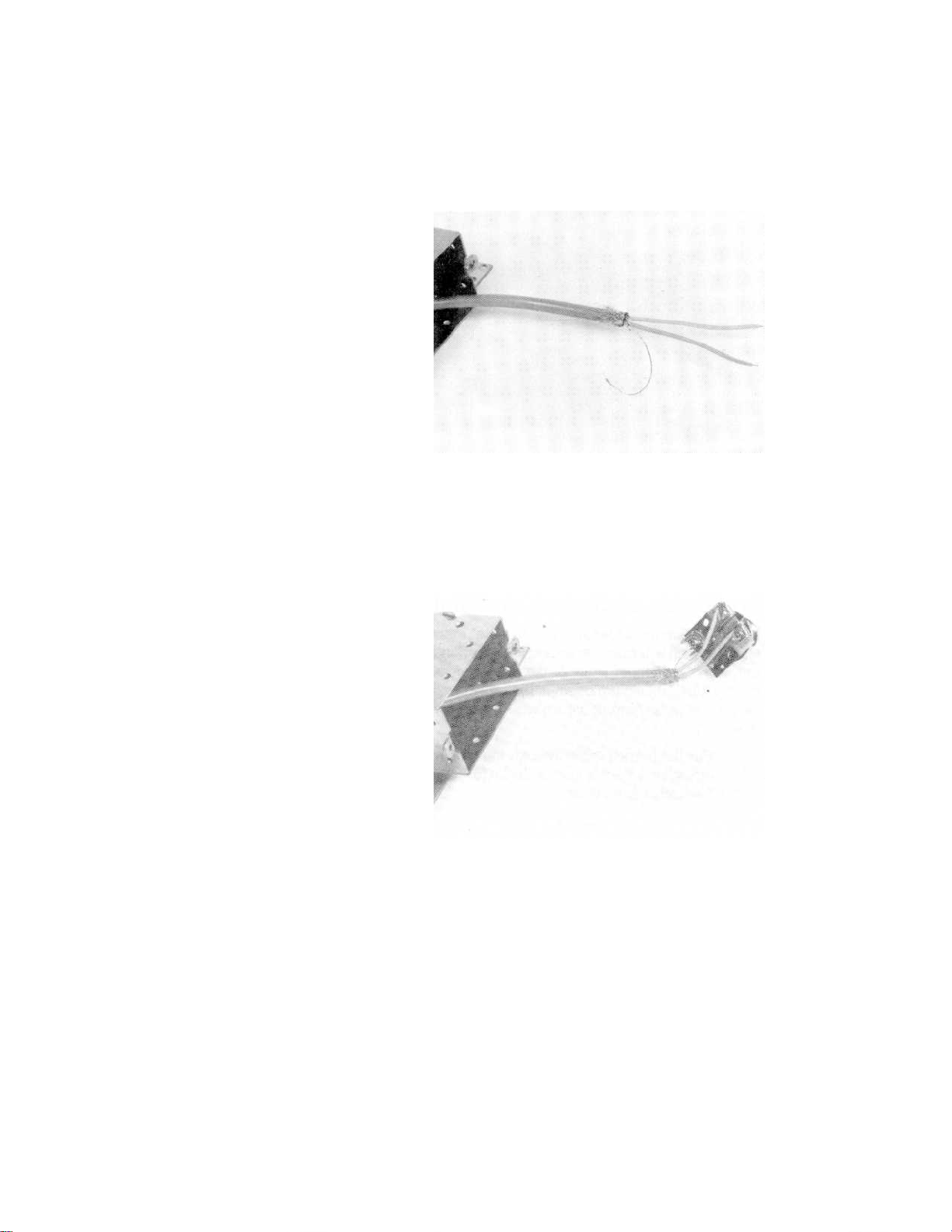
Installation
back the rest of the shield—at least 1.3 cm (1/2 inch)—OVER THE
CABLE INSULATION.
d. Remove the foil and filler strips from the cable end and separate the
PINK, BLUE, and drain wires.
e. Attach the drain wire to the GND terminal connector on the PC board/
SDN connector assembly. Wrap the drain wire completely around the
terminal screw.
f. With the drain wire extended directly below the PC board/connector
assembly, lay the PINK and BLUE wires over their respective terminal
connectors and trim the ends at the appropriate length to allow the
bare end of the PINK and BLUE wires to be wrapped clockwise threequarters of the way around the terminal screw.
g. Strip off the insulation from the wire ends. Using long nose pliers, bend
the bare wire end into a loop and attach to the appropriate terminal.
h. Place the PC board/SDN connector assembly into the shield cover and
secure it in place using the knurled ring. Make sure the connector fits
8-13
Page 76

Install Cable Enclosures, Wall Boxes, and Branch Cables
correctly into the key slot of the shield cover and it is fastened
securely.
i. Place the cable insulation with folded back braided wire on the bottom
edge of the shield cover and clamp securely. The braid should be
securely fastened to ensure a good electrical connection between braid
and shield.
8-14
j. Attach the protective plate to the top of the shield cover using the two
screws provided and tighten securely.
Page 77
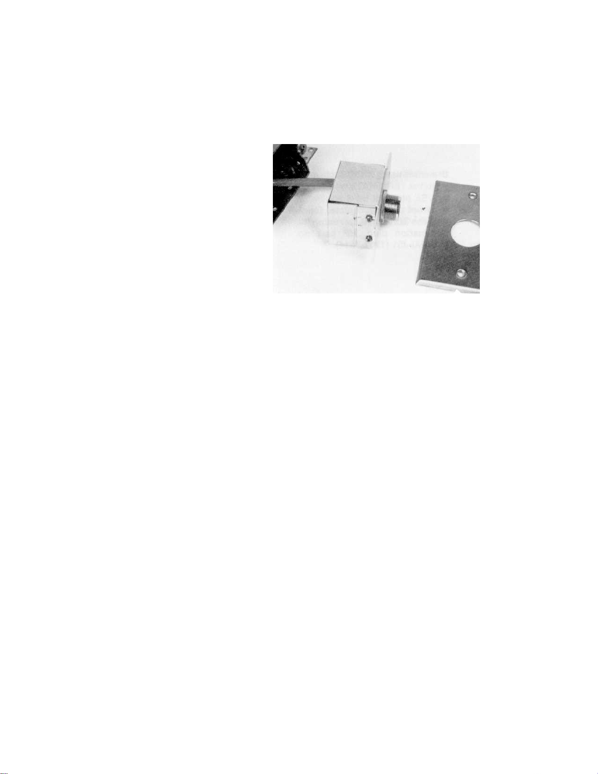
Installation
k. Insert the shield cover/SDN connector assembly into the switch wall
box. Carefully loop the excess branch cable behind the shield cover and
push in as far as possible.
l. Attach the faceplate to the switch wall box. Align the holes of the shield
cover with the switch wall box and secure the faceplate using the
screws provided.
SDN on UTP Wall Boxes Connections
Wall Box Kits for SDN on UTP are available to fit both standard U.S.
electrical wall boxes [NEMA, single or dual gang with conduit knockouts,
minimum depth = 4.0 cm (1.6 in.)] and typical European wall boxes
[minimum depth = 4.0 cm (1.6 in.)]. SDN/UTP single gang switch, Wall Box
Kits are shown below for both U.S. (Options J12 and J13) and European
(Options JJ1 and JJ2) versions. The kits include the following components.
1. SDN/UTP shield box (with cover) for SDN connection to UTP cable PCB
assembly (compatible with world wide requirements and screened
twisted pair (STP) cable).
2. PCB assembly (in the connector box).
3. SDN connector for LDC cable.
4. Black anodized ring nut on SDN connector for external identification
of SDN on UTP installation.
5. Standard, prepunched, single gang wall plate for SDN/UTP connector.
6. Screw connection for cable earth ground (European version).
7. Tie wrap for use with Screened Twisted Pair (ScTP) cable only (not
shown).
8-15
Page 78

Install Cable Enclosures, Wall Boxes, and Branch Cables
UTP Connections
It is the customer’s responsibility to install the Category 5 UTP cable,
terminate both ends, and certify the UTP installation. RJ45 connections
must be at the ACC and 110 edge connector must be terminated at the wall
box.
Parts Required
Equipment Needed
Parts required to install the UTP cable are listed in the following table.
Quantity Description Part Numbers
1 per ACC branch LDC Cable 78599AI
Option J03 – 3 ft. LDC cable
Option J06 – 6 ft. LDC cable
Option J10 – 10 ft. LDC cable
Option J20 – 20 ft. LDC cable
1 per ACC branch SDN/UTP single
gang wall box
unit
SDN/UTP dual
gang wall box kit
1 per SDC or
XSDC cable
Equipment needed to install the UTP cable is listed in the following table.
RJ45 to
connector cable
78599AI
Option J12 – Quantity 1
Option J13 – Quantity 8
Option JJ1 – Quantity 1 (European)
Option JJ2 – Quantity 8 (European)
78599AI
Option J14 – Quantity 1
Option J15 – Quantity 8
M3199AI J03
8-16
Quantity Description Part Numbers
1 Microtest PentaScanner Kit Contact Anixter (see notes
below)
1 Test Adapter, 568A wiring Amp 558908-I
1 Test Adapter, 568B wiring Amp 558909-1
1 110 Punch Tool
1 Screwdriver - Pozi drive #1
1 Screwdriver - Pozi drive #2
Page 79

Installation
Note
Before performing the installation, familiarize yourself with the operation of
the Microtest PentaScanner.
The Microtest PentaScanner cannot be ordered from Agilent. It can be
ordered from the Anixter Corporation.
Fax or mail a purchase order to:
Anixter Corp.
200 Denton Drive
Methuen, Ma. 01844
USA
Phone: 978-682-8870
Fax: 978-682-4744
Provide the following information:
Part number: HP-161851
Bill-to address
Ship-to address
Select the language and voltage you require for your application from the
following list. If no specification is made, a North American, 11O V version
will be supplied.
North American
110 V
French
German
Spanish
Italian
UK
Australian
Japanese
22O V or 11O V
220 V
22OV or 110 V
220V
240 V, 220 V, or 11O V
240 V
11O V
8-17
Page 80

Procedures
Procedures
ACC Procedures (78581B)
The following procedures describe the detailed steps for installing a Serial
Distribution Network (SDN) between an instrument wall box and the ACC
using UTP cable.
The customer is responsible for the following steps:
1. Terminate UTP cable at the ACC end with RJ45 connector.
2. Terminate UTP cable at Wall Box with a 110 edge connector (AMP).
Agilent recommends that the above steps be performed by a licensed LAN
installer who will certify the terminated UTP cable. The Agilent installer is
responsible for the following steps:
1. Qualify UTP cable if necessary. See “Qualify UTP Cable” on page 8-21.
2. Complete wall box installation. See “SDN on UTP Wall Boxes
3. Perform final operational check.
Connections” on page 8-15.
Perform Final
Operational Check
Symptom Possible Cause Corrective Action
Bed not showing at
Central Station
No Overview capability ACC is off Plug in power cord.
No LEDs on ACC Defective power supply or power not
1. Plug in ACC.
2. Inspect ACC for proper operation of LEDs.
3. Turn on Central Station and all bedsides.
4. Verify that all bedsides have functioning Overview screens.
5. Verify that all bedsides are displayed at the Central Station.
If all instruments do not operate properly, use the troubleshooting
table below to correct the problem.
Bed connected to wrong branch at ACC. Move cable to the port that is
connected to the bedside.
Bed not configured at Central Station Configure bed at Central
Station.
Overview not configured On at bedside Configure Overview On at
Bedside. Check ACC for fire
axes.
Ensure that power cord is
connected.
connected.
Replace power supply.
8-18
6. Perform test and inspection matrix.
Page 81

Serial Communication Controller (SCC) Procedures (78581A)
The following procedures describe the detailed steps for installing a Serial
Distribution Network (SDN) between an instrument wall box and the
Serial Communication Controller (SCC) using UTP cable. Procedures for
connecting the SCC to a patch panel are given for both RJ 45 and 110
punch-down type systems.
Agilent recommends that these steps be performed by a licensed LAN
installer who will certify the terminated UTP cable.
Agilent is responsible for the following steps:
1. Qualify UTP cable
2. Complete wall box installation
3. Wire patch cable to SCC
4. Connect patch cable to patch panel
5. Perform final operational check
Installation
Terminate UTP Cable at
Patch Panel
1. Locate SCC.
2. Locate SCC patch panel for new installation.
Patch panel must be within 8 feet of the SCC.
3. Determine if UTP cable been terminated at patch panel.
• If YES, proceed to next section, “Terminate UTP Cable at Wall
Box.”
• If NO, terminate patch panel as follows.
4. Terminate UTP cable at patch panel.
a. Strip back UTP cable insulation no more than 2 inches, keeping
twists in wire pairs within 0.5 inch of termination at patch panel.
b. Lay twisted cable over patch panel punch-down connectors.
c. Using punch tool, punch wires following color code on rear of patch
panel. For ease of installation, start wiring patch panel at lowest
port and proceed to highest port.
Refer to the following diagram for UTP cable color coding and proper wire
connection.
8-19
Page 82

Procedures
Terminate UTP Cable at
Wall Box
1. Go to bedside wall box and record any numbers associated with UTP
cable.
2. Terminate wall box end of UTP cable to match diagram below.
a. Strip back UTP cable insulation no more than 2 inches, keeping
twists in wire pairs within 0.5 inch of termination to punch down
edge connector.
b. Lay twisted pairs over edge connector.
c. Using punch tool, punch connector as shown below following color
coding shown above.
If using a barrel style connector instead of a punch down style,
insert connector ends into appropriate slots of stuffer cap.
Make sure conductor ends are flush with back of conductor slots.
An optional stuffer punch down tool (AMP 556706-1) can be used to
insert wires into the edge connector stuffer cap.
d. Have the UTP installation certified as Category 5 by a licensed LAN
installer.
8-20
Page 83

Installation
Qualify UTP Cable
Note
If the UTP cable installation has not been qualified within the past 12
weeks, Agilent or an Agilent representative must requalify the installation.
Following is the procedure for qualification.
Calibration of the PentaScanner must be done the day of the test.
1. Insert newly terminated end of wall box UTP edge connector into test
adapter B.
2. Attach the short RJ 45 patch cord between Microtest 2-way Injector
and test adapter B.
3. Go to patch panel near SCC.
4. Attach an RJ 45 patch cord between Microtest PentaScanner Tester
and patch panel port to be tested.
5. Turn on PentaScanner and start Autotest.
If tester displays “Injector not found,” move RJ 45 patch cord until
correct port is found. This port should be labeled as that bed number.
6. Perform Autotest (see PentaScanner User’s Guide for proper use of
Microtest PentaScanner).
The following table gives acceptable values.
Tests Specifications
Cable Length Less than 90 meters (295 ft.)
Splices in Cable None
DC Resistance Less than 8.5 ohms
Mutual Capacitance Less than 5.6 nanoFarads per 90 meters (295 ft.)
Structural return loss 1 - 20 Mhz: 23 dB
20 -100 Mhz: 23 -10 log (f120) dB
Impedance 100 ohms +1- 15%
8-21
Page 84

Procedures
Tests Specifications
Attenuation (per 90
meters) @200C)
NEXT (>90 meters)
7. Record test values and port label.
If port has no label, assign a bed or branch number to that port.
Freq.(Mhz) NEXT (dB) Attenuation
0.772 64 1.6
1.0 62 1.9
4.0 53 3.9
8.0 48 5.3
10.0 47 5.9
16.0 44 7.4
20.0 42 8.3
25.0 41 9.5
31.25 39 10.6
62.5 35 15.4
100.0 32 19.8
(dB)
Note
Symptom Possible Cause Corrective Action
Failed cable-length test Cable> 90 m (295 ft.) Install SDC or XSDC cable
Failed noise test Noise sources close to UTP
Failed splice-in-cable test Damaged UTP Cable Re-pull UTP cable
Failed wire-map test Broken wire in UTP Cable Re-terminate indicated wire, or
Test values may be stored in the PentaScanner and then downloaded to a PC
or printer to obtain a printed report of all tested branches. The PentaScanner
automatically calculates and reports all tests with either a pass or fail status.
8. If test values meet specifications, the cable is qualified.
If not, use the troubleshooting table below.
Install SDC or ScTP cable
cable
re-pull UTP cable
Crossed pairs in UTP Cable Re-terminate indicated pairs
Wrong adapter used in
PentaScanner test
Match PentaScanner adapter to
patch panel wiring — A or B
8-22
Page 85

Installation
Symptom Possible Cause Corrective Action
Failed impedance test Check cable jacket for
Category 5
Failed NEXT test Cross talk from other pairs Re-terminate punchdown
Check cable jacket for
Category 5
When cables are qualified for all bedsides and central station locations,
remove Tester and Injector.
If cable not Category 5, repull
Category 5 cable
connections at both ends. If it
still fails, check wiring for wiring
scheme — A or B.
If cable not Category 5, repull
Category 5 cable
Install Local Distribution Cables
Installation of local distribution cables (LDC) is the responsibility of
Agilent Technologies service personnel. Refer to “SDN Installation
Restrictions and Limitations” on page 8-4.
Local distribution cables (LDC) are used for local series connection from
the wall box to the instruments downstream. Up to two (2) separate
instruments may be connected together via LDCs to each wall box—one
patient per branch.
The local distribution cables are supplied in four standard lengths to meet
most installation requirements. Unique keying along with color-coding
connectors prevent erroneous cable connections. Each connector contains
a metal retaining ring that holds the LDC cable to the connector receptacle
to prevent accidental disconnection and to provide continuous shielding
and ground path. The standard length LDCs are listed below.
Table 8-2: Standard Length LDCs
LDC Length
0.9 meters (3 ft.) 78599AI-JO3 (8120-3591)
1.8 meters (6 ft.) 78599AI-J06 (8120-3587)
3.0 meters (10 ft.) 78599AI-J10 (8120-3588)
6.1 meters (20 ft.) 78599AI-J20 (8120-3589)
The variable length LDC is available to meet the installation requirements
not fulfilled by the standard length LDCs. The variable length LDC is
terminated on one end with a standard gray color-coded connector and
open on the other end. This open end allows the cable to be cut to any
Agilent Technologies
Part Number
8-23
Page 86

Procedures
desired length and terminated at the installation site with the associated
colored connector. Raw LDC and up/downstream connectors are available
also to fabricate LDCs as required.
Table 8-3: Variable Length LDCs
Variable Length LDC Agilent Technologies Part Number
15.2 meters (50 ft.) 78599AI-J50. Includes molded connector one end and
downstream connector to be installed on other end.
15.2 meters (50 ft.) 78599Al-J54. Includes one 15.2 cm (50 ft.) length of
unterminated LDC.
78599AI-J52. Includes two SDN connectors—upstream
and downstream.
Instructions for terminating the SDN connector onto the open end of the
LDC are specified in detail on page 8-25. The length of the LDC is subject
to the restrictions and limitations specified on page 8-4.
Connect LDC from Wall Box to Instrument(s)
Connectors on the local distribution cables are mechanically keyed and
color-coded to prevent erroneous connection. The color on the connector
end of the LDC is either GRAY (DOWNSTREAM) or BROWN (UPSTREAM).
The upstream cable direction is from the instrument(s) towards the wall
box (ACC) and the downstream cable direction is from the wall box
towards the instrument(s). The LDC connectors and receptacles are
illustrated in Figure 8-3.
8-24
Figure 8-3. LDC Connections from Bedside Instruments to Wall Box
Page 87

Installation
a. Connect the gray color-coded connector to the wall box receptacle.
Align the slots in the connector with the keys in the receptacle and
push in as far as possible. Secure the connector to the receptacle by
tightening the retaining ring onto the receptacle.
b. Connect the brown color-coded connector on the other end of the LDC
to the mating brown color-coded connector located on the instrument
(bedside monitor). Align the slots in the connector with the keys in the
receptacle and push in as far as possible. Secure the connector to the
receptacle by tightening the retaining ring onto the receptacle.
c. Connect any additional patient related instruments in series using
other local distribution cables. Observe the upstream and downstream
color-coding scheme as described above.
Caution
The sum total of all the lengths of LDCs must be less than 15.2 meters
(50 ft.).
Terminate Variable Length LDC
The following procedures can be used to terminate the variable length
LDC cable kit Agilent Technologies part number 78599AI-J50 and, also, to
terminate the 2-connector kit, Agilent Technologies part number 785-99AlJ52 and 78599Al-J54.
1. Measure and cut the open end of the LDC to the desired length. Leave
at least 0.3 meters (1 ft.) overrun to facilitate termination and
instrument servicing.
2. Insert the open end of the cable through the connector hardware as
illustrated below.
3. Strip off approximately 2.5 cm (1 in.) of insulation from the cable end
exposing the braided shield.
4. Use care not to cut or damage the braided shield.
5. Unbraid and peel back the braided shield. Separate the drain/ground
wires from the shield and twist together. Fold back the braided shield
over the cable insulation.
6. Cut off the foil and filler strips from the cable end.
7. Strip off approximately 6.3 mm (1/4 in.) of insulation from each of the
four wire ends to allow the bared end to be soldered onto the
connector contacts.
8. Solder the four wire ends and the drain wire to the respective terminal
contacts as indicated below.
8-25
Page 88

Procedures
9. Connect:
PINK WIRE (positive) ---------->pin A
BLACK WIRE (negative) ---------- >pin B
GRAY WIRE (positive) ---------- >pin C
DRAIN WIRE (GND) ---------- >pin D
BLUE WIRE (negative) ---------- >pin E
10. Slide the connector locking ring forward over the connector as far as
possible.
11. Screw the backshell onto the connector and tighten.
12. Gently, slide the cable clamp over the folded back braided shield and
screw the clamp onto the backshell. Do not twist the connector; twist
the cable clamp.
13. Tighten down both cable clamps uniformly. Trim off excess braided
shield.
Terminate SDC and XSDC Connections
The following procedures can be used to terminate the variable length SDC
or XSDC cable. You will need the 78599AI Option J52 kit. From this kit,
use the supplied light gray, male connector.
1. Measure and cut the open end of the SDC or XSDC cable to the desired
length. Leave at least 0.3 meters (1 ft.) overrun to facilitate termination
and instrument servicing.
2. Insert the open end of the cable through the connector hardware as
illustrated in the previous figure.
3. Strip off approximately 2.5 cm (1 in.) of insulation from the cable end
exposing the braided shield.
4. Use care not to cut or damage the braided shield.
5. Unbraid and peel back the braided shield. Separate the drain/ground
wires from the shield and twist together. Fold back the braided shield
over the cable insulation.
6. Cut off the foil and filler strips from the cable end.
8-26
Page 89

Installation
7. Strip off approximately 6.3 mm (1/4 in.) of insulation from each of the
two wire ends to allow the bared end to be soldered onto the connector
contacts.
8. Solder the two wire ends and the drain wire to the respective terminal
contacts as indicated below.
9. Connect:
PINK WIRE (positive) ---------->pin A
DRAIN WIRE (GND) ---------- >pins B, C, and D
BLUE WIRE (negative) ---------- >pin E
10. Slide the connector locking ring forward over the connector as far as
possible.
11. Screw the backshell onto the connector and tighten.
12. Gently, slide the cable clamp over the folded back braided shield and
screw the clamp onto the backshell. Do not twist the connector; twist
the cable clamp.
13. Tighten down both cable clamps uniformly. Trim off excess braided
shield.
14. After you create the cable, screw the connector to the M3199AI option
J03 (78581-60350).
15. Plug the RJ45 end into the appropriate port on the ACC. Refer to the
following figures.
8-27
Page 90
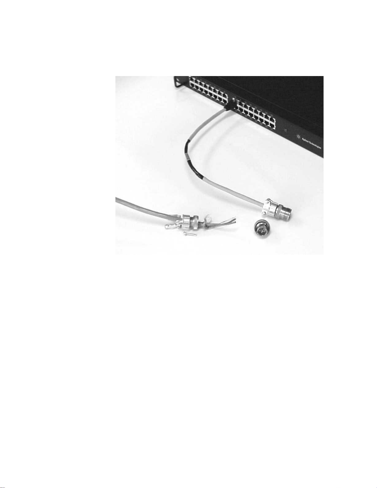
Procedures
8-28
Page 91

Section 9: SDN/ACC System
Compliance with IEC 60601-1-1
Connecting the ACC to other medical and non-medical devices creates a
medical electrical system. Such systems must comply with IEC 60601-1-1,
the Collateral standard to the General Medical Safety standard (IEC
60601) that specifies medical electrical system safety requirements. This
standard was developed to address safety issues raised by the increasing
sophistication of medical systems, interfacing of medical equipment to
other devices, and migration of computers and laboratory instrumentation
into the patient care environment. This standard is primarily intended for
the systems integrator (installer) who creates the medical system.
SDN/ACC System Safety
Safety
The basic philosophy of this system safety standard is to assure that
connecting a medical device to any other device will not cause a safety
hazard for the patient, the operator, or their surroundings. That is, any
system as a whole, or any non-medical device in the patient care vicinity,
must provide the same level of safety as an individual medical device that
complies with 60601-1.
In practice, this means that the combined chassis leakage current of a
medical device and any directly interconnected device must be less than
500 µA (300 µA in the US). If the combined leakage current exceeds 500
µA, the system integrator is responsible for taking actions to reduce the
leakage current and bring the system into compliance.
responsible for indicating in their product labeling appropriate steps for an
integrator to take to bring a system into compliance.
IEC 60601-1-1 specifically allows the use of equipment that complies with
IEC XXX (for example, IEC 60950 for computers or IEC 61010 for
laboratory equipment) in the patient care environment provided that the
chassis leakage current meets the medical specifications. Meeting these
specifications may require the use of a separating transformer. This
means, for example, that an IEC 60950 compliant device (for example, a
Vectra computer) may be placed next to a patient if it is powered through
a separating transformer.
Manufacturers are
9-1
Page 92

Device Grounding on the SDN
Device Groundi ng on the SDN
SDN is a ground referenced communication protocol. It requires that the
chassis of each device connected to the SDN be interconnected for proper
operation. Failure to maintain this connection may result in
communication errors and poor performance. In order to maintain a safe
system, each device may also require a redundant Protective Earth (PE).
The ACC has been designed to use a redundant PE to insure compliance
with IEC 601-1-1 when connected to an SDN. The second PE connection
insures system safety. When the ACC is powered using electrical conduit,
the conduit provides the second PE. But when the ACC is powered using a
power cord, the second PE can be made using the green/yellow wire
exiting the ACC. This wire should be connected to the building ground.
The SDN wall box provides for attachment of a PE connection. This
connection point should be connected to the building ground. The second
PE connections along with measurement of the voltage between the ACC
and any SDN medical device ensures system safety.
9-2
Figure 9-1. Second Ground on Rear of ACC
Page 93

SDN Specifications
SDN/ACC Specifications
Section 10: SDN/ACC
Specifications
Table 10-1: SDN Specifications
SDN System
Specifications
Patients Up to 24 patients may be connected to the
SDN
Central Stations Up to 6 information centers may be
connected to the SDN.
Computer Systems Up to 2 computer systems may be
connected to the SDN
SDN Instrumentation Only compatible Agilent instruments may
be connected to the SDN
Instruments Connected to
a Branch
ACC Branch Wiring ACC Branches #1 through #24 are
Up to 2 instruments may be connected to
each branch of the SDN (one patient per
branch) with a maximum of six “speedy
cards”
dedicated for patient connected
instruments. Only one patient per branch.
ACC Branches #0, and #25 through #31 are
dedicated for non-patient connected
instruments (ICs and computer systems).
Value
Wall Box Dimensions Only standard size, NEMA, single- or dual-
gang, switch wall boxes with conduit
knockouts (KOs) may be used. Minimum
depth = 7.0 cm (2.75 in.).
SDN Grounding The maximum difference in ground
potential between the third wire ground
delivered to an ACC and the third wire
ground delivered to any of its SDN
instruments, with the SDN system and local
distribution cables disconnected, is 500 mV
rms.
10-1
Page 94

SDN Specifications
SDN System
Specifications
SDN Data Transmission
Rate
SDN System Distribution
Cables
Value
Clock rate of 3.6 Mbits provides a maximum
of 7700 useable 12-bit data words per
second.
• All XSDC and SDC cables may be supplied
by Agilent.
• Plenum rated Cat. 5 UTP cable can be
supplied by either Agilent or the
customer.
• Each branch cable run from the ACC to a
wall box MUST BE CONTINUOUS; no
splicing, no mixing cable types.
•Maximum branch cable length:
ACC standard distribution cable length
must be less than 152 meters (500 feet)
for SDC.
XSDC extended system distribution cable
length must be less than 304 meters (1000
feet).
UTP cable length must be less than 90
meters (295 feet). M3199AI option P01.
• Up to 2 separate XSDCs may be connected
to the ACC.
• Up to 2 local distribution cables (LDC)
and 2 instruments may be linked to one
branch. Maximum total length of all LDCs
on a branch must be less than 15 meters
(50 ft.).
• Cable enclosures (troughs, raceways,
conduit, and so on) must be dedicated to
branch cable runs only.
• Branch cables must be located at least
0.3 m (1 ft.) away from AC power lines, air
conditioning systems, diathermy units,
and so on, to avoid RF and AC
interference.
10-2
Page 95

ACC Specifications
SDN/ACC Specifications
Table 10-2: ACC Specifications
Electrical Characteristics Value
Power Requirements 100 to 240 VAC -10% to +6% 50-60 Hz
Power Consumption 80 VA
Heat Dissipation 51.6 kg/cal/hr
(204.8 BTU/hr)
Line Conditioning None
Leakage Current Less than 300 microamps
–Class I
– Equipment not suitable for use in the presence of a flammable
anesthetic mixture with air, oxygen, or nitrous oxide.
– IPX0 enclosure not protected against ingress of liquids.
– Mode of operation: Continuous
Table 10-3: Physical Characteristics
Physical Characteristics Value
Dimensions 1.735" (4.41 cm) x 17.665" (44.87 cm) x
17.25" (43.8 cm) (without wings)
Dimensions of optional
wall mount assembly
Weight 14.1 pounds (6.4 kg)
Weight with wall mount
assembly
Service Access Ability to pull ACC forward in the rack-
2.5" (6 cm) x 20.0" (51 cm) x 17.4" (44 cm)
24.2 pounds (11.0 kg)
mounted option leaving power cord and
secondary ground cable long. LEDs are
visible with cover on, but replacement
requires removal.
10-3
Page 96

Cleaning
Table 10-4: Environmental Characteristics
Cleaning
Environmental
Characteristics
Operating Temperature
Storage Temperature
Humidity
Altitude Operating = up to 4600 meters
Under normal conditions, cleaning is not required. However if you wish to
clean the ACC:
1. Unplug the ACC from the power source.
2. Wipe external surfaces with soft cloth dampened in soapy water
(wring out excess water). Be sure not to get fluid inside the ACC.
3. Let the ACC dry completely before use.
o
0
to 55o C (32o F to 131o C)
o
C to 75o C (-40o F to 167 oF)
-40
Up to 95% RH @ 40
(15,000 ft.)
Non-operating = up to 15,300 meters
(50,000 ft.)
Value
o
C (104o F)
System Symbols
10-4
The following is an explanation of the symbols found on the hardware
components of the Agilent CareNet Controller:
Symbol Explanation
AC Line Current.
Catalog Number
Date of Manufacture
Page 97

Symbol Explanation
Protective Earth (Ground)
Serial Number
The Agilent Serial Distribution Network
(SDN)/Agilent CareNet Controller (ACC)
complies with the requirements of the
Council Directive 93/42/EEC of 14 June
1993 concerning medical devices and
carries CE-marking accordingly
Canadian Radio Equipment Compliance
(Canada Only)
SDN/ACC Specifications
Contacts
For sale by prescription only.
Authorized EU Repres entative
Agilent Technologies Deutschland GmbH
Healthcare Solutions Group
Herrenberger Strasse 130
110-140
71034 Boeblingen
Germany
Fax: (+49) 7031 464 1552
10-5
Page 98

Contacts
10-6
Page 99

Index
A
ACC
,1-5
defined
error conditions
mounting location
power failure
power indicator
power up and down
preventive maintenance
rack mounting
restart
theory of operation
troubleshooting
wall mounting
Agilent CareNet Controller. See ACC
architect’s checklist
autopoll mode
,1-1
,2-13
,8-6
,1-3
,1-5
,4-1
,4-1
,8-6
,1-3
,1-4
,4-1
,8-8
,1-1
,7-6
,2-8
B
body
instrument message
branch cable installation
branch cables
part numbers
branch cables installation
,1-6
,2-10
,8-11
,1-7
,8-9
C
cable verification
cables
, 1-6–1-7
branch
LDC
checklist
Agilent rep for established hospital
Agilent rep for new hospital
architect
hospital rep
checklists
component installation
conduit size selecting
configuration review
connecting branch cables to switch wall boxes
12, 8-15
connecting LDC from wall box to instrument
,1-6
,1-6
,7-6
, 7-1–7-8
,3-13
,7-4
,7-2
,7-7
, 6-1–6-4
,8-9
,7-8
,8-24
,8-
E
error messages
NO DATA FROM BED
NO DATA FROM BEDS IN UNIT
NO OVERVIEW FUNCTIONS AVAILABLE
NO RECORDER AVAILABLE
SDN COMM FAILURE — DUPLICATE BED
SDN COMM FAILURE — ILLEGAL BED
NUMBER
SDN EQUIP MALF
extended system distribution cable
,3-5
,3-6
,3-6
,3-6
,3-6
,3-5
,3-5
,3-5
,8-12
F
faceplates
fireaxe
flush
, 1-6–1-7
,2-13
,2-9
G
ground check
,3-16
H
header
,2-10
I
installation
tools, materials, equipment
installation restrictions
installing components
installing local distribution cables
instrument
instrument communication
instrument delimiter
instrument messages
instrument status message
, 8-1–8-28
,8-4
,8-4
, 6-1–6-4
,8-23
,2-10
,2-6
,2-10
,2-10
,2-11
L
LDC cables
local
local distribution cables. See LDC
,1-6
,2-12
,1-6
M
M3199AI
installation materials
messages
system
mounting location of ACC
,2-10
,2-9
,1-8
,8-6
Index-1
Page 100

N
network
,2-12
O
online/offline
,2-12
P
parts list
planning review
poll cycle
poll cycle overflow
power failure
power indicator
power up/down ACC
, 5-1–5-4
,7-8
,1-1,2-7
,2-13
,1-3
,1-5
,4-1
R
rack mounting the ACC
reverification
,3-13
,8-6
S
safety
, 9-1–10-5
SDC
,8-12
SDN
applications
autopoll
branch cables
cabling installation kits
components
configuration example
configurations
data structure
data timing
defined
error message
grounding
installation restrictions
instrument communication
instrument connection
instrument messages
normal operation
operation
OVERVIEW mode
status and error conditions
system description
theory of operation
timing overview
topology
troubleshooting
troubleshooting flowchart
wiring
Serial Distribution Network. See SDN
servicing
site prep
specifications
ACC
,10-3
SDN
,10-1
,2-6
,2-12
,1-7
,1-7
, 1-1, 1-2, 1-7
,1-3,2-5
,1-3
,2-9
,2-11
,1-1
,3-5
,9-2
,8-4
,2-6
,8-1
,2-10
,2-11
,1-1
,2-6
,2-12
, 1-1–1-8
,2-2–2-13
,2-7
,2-5
, 3-1–3-16
,3-4
,8-1
,1-5
, 7-1, 7-8
, 10-1–10-5
standalone instrument verification
standard system distribution cable
star topology
sync tap
system communication verification
system delimiter
system messages
system status word
,2-5
, 2-7, 2-9
,2-9
,2-9
,2-9
T
talk tap
terminating variable length LDC
theory of operation
timing
troubleshooting
,2-9
,2-7
abbreviations
ACC
,4-1
equipment
flowchart
resources
review
SDN
tools
,3-3
,3-4
,3-3
,3-12
, 3-1–3-16
,3-3
, 8-25, 8-26
, 2-1–2-13
,3-2
V
verification
standalone instrument
verification procedures
,7-8
,7-8
W
wall box installation
wall boxes
wall mounting the ACC
wiring installation
, 1-6–1-7
,8-11
,8-8
,8-1
X
XSDC
,8-12
,7-8
,8-12
,8-1
Index-2
 Loading...