

Page 1
User's Guide
HP
Reectometer
8504B
Precision
Page 2
HP part number: 08504-90046
Printed in USA March 1995
1400 Fountaingrove Parkway,
Santa Rosa, CA
95403-1799, USA
Notice.
The information contained in this document is subject to change
without notice. Hewlett-Packard makes no warranty of any kind with regard
to this material, including but not limited to, the implied warranties of
of
shall
this
merchantability
for
liable
be
not
damages
in connection
and
errors
tness
contained
with
for
the
a
particular
herein
or
furnishing,
Hewlett-P
purpose
for
.
incidental
performance
ackard
consequential
or
use
or
,
material.
.
.S
U
the
Restricted
Rights
Government
Rights
the
of
252.227-7013
Commercial
agencies
other
Legend.
subject
is
echnical
T
in
DOD
for
Computer
.
Use
restrictions
to
Data
agencies
Software
duplication,
,
as
Computer
and
subparagraphs
and
,
Restricted
set
or
forth
Software
Rights
disclosure
in
clause
by
subparagraph
at
and
FAR
at
(c)
clause
(c) (1)
(1)
(c)
ARS
DF
the
of
(2)
52.227-19
(ii)
for
c
Copyright Hewlett-P
ackard Company 1992, 1993, 1994, 1995
All Rights Reserved. Reproduction, adaptation, or translation without prior
written permission is prohibited, except as allowed under the copyright laws.
Page 3
WARNING
This is a IEC Class 1 LED product. Do not stare into beam or view
directly with optical instruments. LED radiation is emitted from the
front-panel
TEST PORT
and
REFERENCE EXTENSION A
connectors.
WARNING
ARNING
W
CAUTION
CAUTION
If this instrument is not used as specied, the protection provided by the
equipment could be impaired. This instrument must be used in a normal
condition (in which all means for protection are intact) only.
qualied
operator
No
personnel.
.
covers
Before
switch
installed.
switching
set
is
Assure
Electrostatic
connectors
.
momentarily
touching
void
A
instrument.
the
prevent
buildup of
serviceable
prevent
o
T
on
voltage
the
to
the
discharge
Therefore
the
short
rear-panel
the
sure
Be
static
electrical
this
supply
(ESD)
before
,
center
inside
parts
product,
the
of
voltage
can
connecting
and
connectors
the
that
charge
.
shock
make
power
is
damage
outer
instrument
.
servicing
Refer
LED
and
that
sure
supply
specied
the
in
circuits
cable
any
conductors
without
is
and
properly
to
radiation,
line-voltage
the
correct
the
range
associated
rear-panel
a
to
the
of
touching
rst
earth-grounded
do not
.
with
cable
remove
selector
is
fuse
rear-panel
connector
together
frame
the
.
to
This instrument has been designed and tested in accordance with IEC
Publication 348,
Safety Requirements for Electronic Measuring Apparatus
,
and has been supplied in a safe condition. The instruction documentation
contains information and warnings which must be followed by the user to
ensure safe operation and to maintain the instrument in a safe condition.
,
of
iii
Page 4

The HP 8504B at a glance
The HP 8504B precision reectometer is a high-resolution interferometer
that measures return loss. It is optimized for single-mode ber, but useful
measurements can also be made in multi-mode ber. The precision
reectometer performs measurements at 1300 nm and 1550 nm wavelengths.
Typical applications include:
Measurements of launch optics for lasers and opto-electronic integrated
circuits.
Measurements
connectors,
High-resolution
known
Measurement
refractive
between
High-resolution
Measurements
crystals
.
of passive
and isolators
measurements of
refractive
of
discontinuities
two
measurement
of
index.
bulk
ber-optic devices
.
lightwave path
material
of
index
.
path
of
devices
optic
length,
such
as
lenses
such as
based
couplers
discontinuities
a
on
expressed
AR
,
,
known
transit
as
coatings
attenuators
on
based
distance
.
time
,and
,
a
iv
Page 5
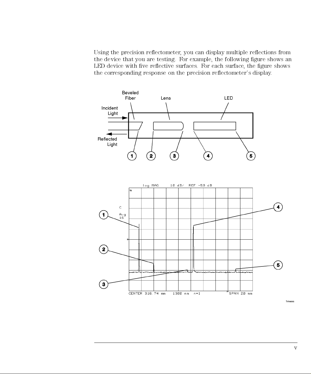
Using the precision reectometer, you can display multiple reections from
the device that you are testing. For example, the following gure shows an
LED device with ve reective surfaces.For each surface, the gure shows
the corresponding response on the precision reectometer's display.
v
Page 6
Guided procedures
reduce measurement
time
The precision reectometer provides
guided setup
and
guided calibration
procedures that help you prepare the instrument for measurements.
These procedures consist of a series of screens that present step-by-step
instructions.
Procedure Task
changed
be
adapters
Front-panel
can
Softkeys select
instrument features
guided setup
Selects light source and calibrates the instrument for
pigtailed or non-pigtailed devices.
guided calibration
Calibrates the instrument.
You can also manually calibrate the instrument for maximum exibility.
guided
for
Chapter
to
Refer
calibrations
should calibrate
You
the instrument
After
Before
The
with
be
a
in
other
\Front-P
to
available
making
precision
9/125
changed or
easily
counterclockwise direction.
adapters
adapter
2
.
the instrument:
any
reectometer's
ber-optic
m
measurement performance
, but
anel Fiber-Optic
types
complete
a
has warmed
measurements.
three
All
.
cables
cleaning.
removed
for
Useful measurements
Adapters"
.
explaination
1
for
up
front-panel
connectors
three
Simply
Chapter
in
guided
of
.
hour
connectors
unscrew
may
5
not
for
setups
are
are
be
complete
a
and
compatible
are
adapters
adapter
each
achievable
optimum.
listing
that
with
Refer
can
of
Many instrument features are available through the use of softkeys. Softkeys
are the eight keys that are located along the right-hand side of the display.
The denitions for these keys are shown on the display next to the key and
change for dierent menus.
vi
Page 7
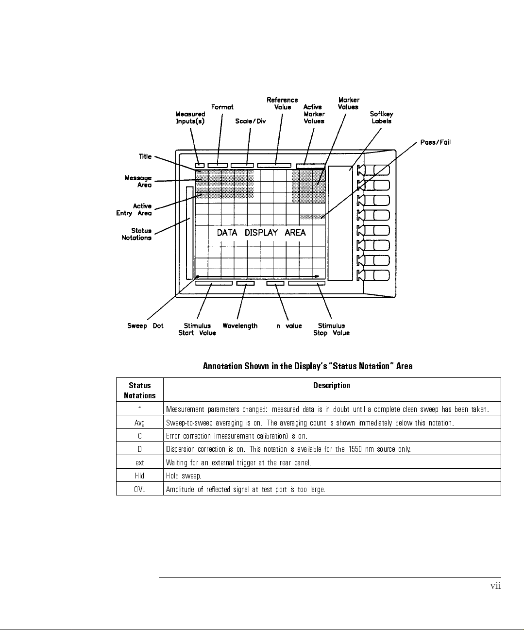
Annotation
Shown
in
the
Display's
\Status
Notation" Area
Status
Description
Notations
* Measurement parameters changed: measured data is in doubt until a complete clean sweep has been taken.
Avg Sweep-to-sweep averaging is on. The averaging count is shown immediately below this notation.
C Error correction (measurement calibration) is on.
D Dispersion correction is on. This notation is available for the 1550 nm source only.
panel.
rear
the
at
trigger
external
for an
ext W
Hld Hold sweep
OVL Amplitude
aiting
.
of
reected
signal
.
large
is too
port
test
at
vii
Page 8
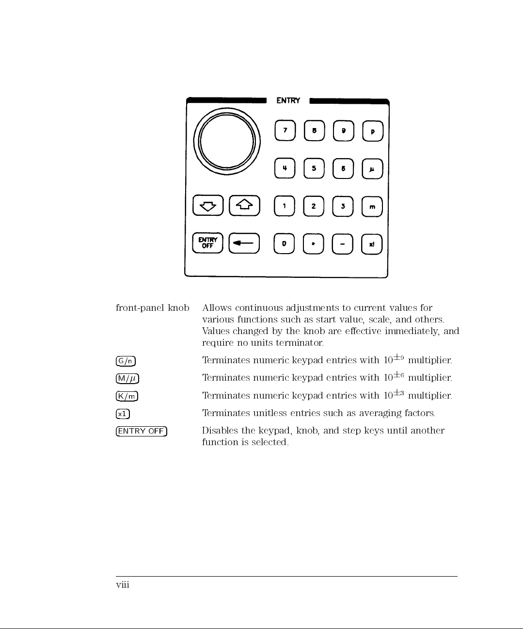
front-panel
4
5
G/n
4
5
M/
4
5
K/m
knob
alues
continuous
functions
changed
Allows
various
V
require no
erminates
T
erminates
T
erminates
T
by
terminator
units
numeric
numeric
numeric
adjustments
start
as
such
knob
the
.
keypad
keypad
keypad
to
value
eective
are
entries
entries
entries
current
scale
,
with
with
with 10
and
for
others
values
,
immediately
9
6
10
multiplier
6
6
10
multiplier
6
3
multiplier
,
.
and
.
.
.
4x15
4
ENTRY OFF
viii
Terminates unitless entries such as averaging factors.
5
Disables the keypad, knob, and step keys until another
function is selected.
Page 9
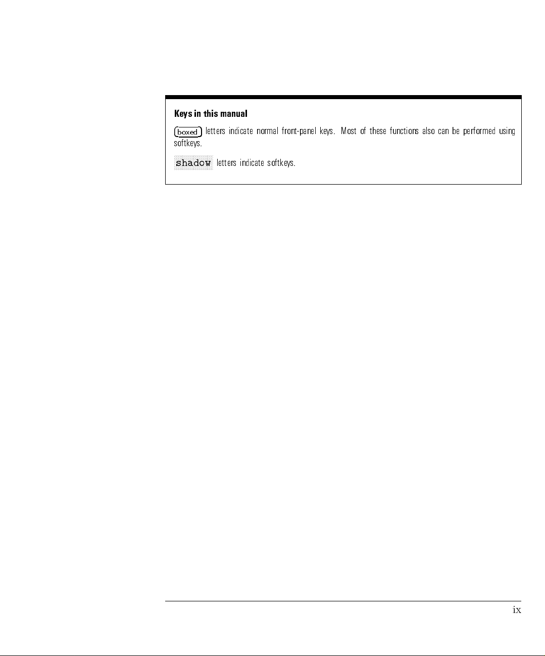
Keys in this manual
4
5
letters indicate normal front-panel keys. Most of these functions also can be performed using
boxed
softkeys.
NNNNNNNNNNNNNNNNNNNN
shadow
letters indicate softkeys.
ix
Page 10
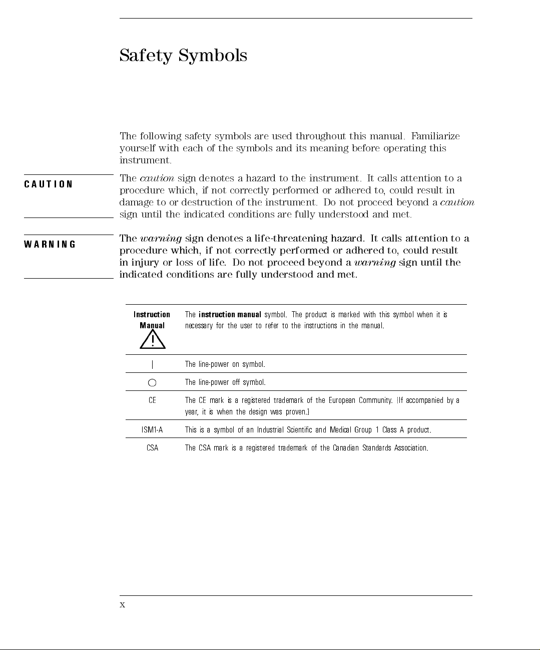
CAUTION
Safety Symbols
The following safety symbols are used throughout this manual. Familiarize
yourself with each of the symbols and its meaning before operating this
instrument.
The
caution
sign denotes a hazard to the instrument. It calls attention to a
procedure which, if not correctly performed or adhered to, could result in
damage to or destruction of the instrument. Do not proceed beyond a
caution
sign until the indicated conditions are fully understood and met.
attention to
calls
adhered
a
warning
with
manual.
the
in
It
this symbol
,could
to
sign until
result
when
beyond
and
product
instructions
hazard.
or
met.
marked
is
life-threatening
.
are
Do
the
a
correctly
proceed
not
understood
fully
symbol.
manual
refer
to
user
performed
The
the
to
denotes
warning
G
N
I
N
R
A
W
The
procedure
injury
in
indicated
Instruction
Manual
sign
which,
of
loss
or
conditions
instruction
The
necessary
if
not
life
for
a
the
is
it
L
symbol.
mark
when the
on
o
is
symbol.
registered
a
design was
trademark
proven.)
a
y
accompanied
(If
European
the
of
Community
.
b
line-power
j
CE
The
The
The
year
line-power
CE
it is
,
ISM1-A This is a symbol of an Industrial Scientic and Medical Group 1 Class A product.
CSA The CSA mark is a registered trademark of the Canadian Standards Association.
x
Page 11
Certication and Assistance
Hewlett-Packard Company certies that this product met its published
specications at the time of shipment from the factory.Hewlett-Packard
further certies that its calibration measurements are traceable to the United
States National Institute of Standards and Technology (NIST), to the extent
allowed by the Institute's calibration facility, and to the calibration facilities of
other International Standards Organization members.
Product maintenance agreements and other customer assistance agreements
available
are
any assistance
For
Oce.
Hewlett-P
for
, contact
ackard
your nearest
products.
Hewlett-P
ackard
Sales
and
Service
xi
Page 12

Warranty
This Hewlett-Packard instrument product is warranted against defects in
material and workmanship for a period of one year from date of shipment.
During the warranty period, Hewlett-Packard Company will, at its option,
either repair or replace products which prove to be defective.
For warranty service or repair, this product must be returned to a service
facility designated by Hewlett-Packard. Buyer shall prepay shipping charges
to Hewlett-Packard and Hewlett-Packard shall pay shipping charges to return
duties
product
the
and taxes
.
Buyer
to
for products
However
,
returned to
Buyer
shall
Hewlett-Packard
pay
shipping
all
from
charges
another
,
country
.
,
Hewlett-Packard
Hewlett-P
instructions
does
rmware
The
or
ackard
when
warrant
not
be
will
foregoing
inadequate
interfacing,
environmental
maintenance
or
NO
OTHER
W
SPECIFICALL
MERCHANT
ABILITY
warrants that
for use
with an
properly installed
the
that
uninterrupted
warranty
maintenance
unauthorized
specications
.
ARRANTY
DISCLAIMS
Y
AND
its software
instrument
operation
error-free
or
not
shall
Buyer
by
modication
for
EXPRESSED
IS
THE
FITNESS
on that
the
of
to
apply
Buyer-supplied
,
or
product,
the
OR
IMPLIED
FOR
and rmware
execute
will
instrument.
instrument,
tion
a
Limit
.
operation
,
improper
or
resulting
defects
misuse
IMPLIED
ARRANTIES
W
ARTICULAR
P
A
designated
programming
its
Hewlett-P
software
or
W
of
software
site
HEWLETT-P
.
OF
PURPOSE.
by
ackard
or
,
arranty
improper
from
or
outside
preparation
A
of
CKARD
Exclusive Remedies
THE REMEDIES PROVIDED HEREIN ARE BUYER'S SOLE AND EXCLUSIVE
REMEDIES. HEWLETT-PACKARD SHALL NOT BE LIABLE FOR ANY
DIRECT,
AMA
D
LEGAL
INDIRECT, SPECIAL, INCIDENTAL, OR CONSEQUENTIAL
ANY
OR
,
TORT
,
,
GES
THEORY
WHETHER
.
ASED
B
ON CONTRA
CT
OTHER
the
xii
Page 13
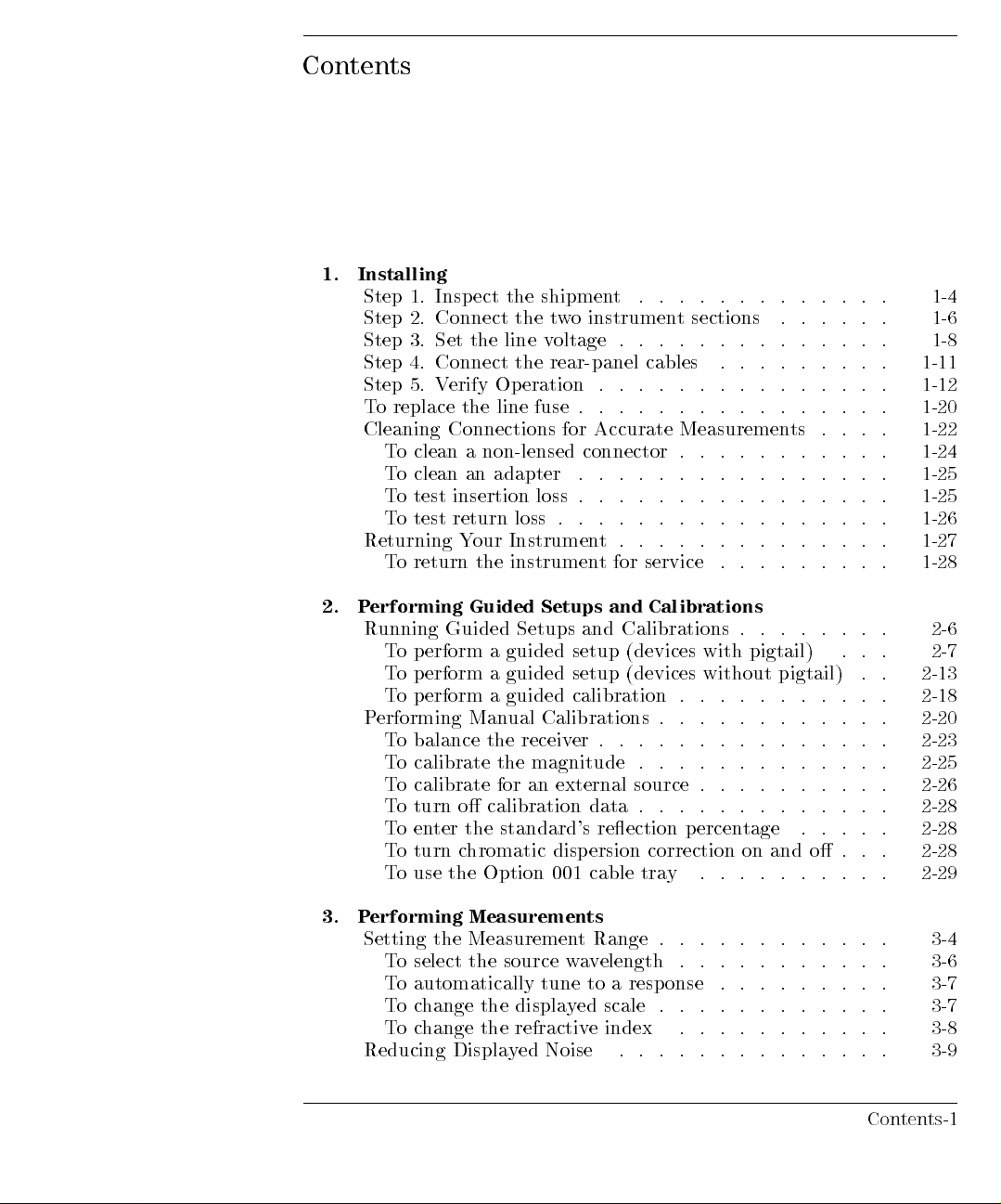
Contents
1. Installing
Step 1. Inspect the shipment . . . . . . . . . . . . .
Step 2. Connect the two instrument sections . . . . . .
Step 3. Set the line voltage . . . . . . . . . . . . . .
Step 4. Connect the rear-panel cables . . . . . . . . .
Step 5. Verify Operation . . . . . . . . . . . . . . .
To replace the line fuse . . . . . . . . . . . . . . . .
Cleaning Connections
T
T
T
T
Returning
T
erforming
P
2.
Running
T
T
T
erforming
P
T
T
To calibrate for an external source . . . . . . . . . .
To turn o calibration data . . . . . . . . . . . . .
Toenter the standard's reection percentage . . . . .
Toturnchromatic dispersion correction on and o . . .
To use the Option 001 cable tray . . . . . . . . . .
clean
o
clean
o
test
o
test
o
return
o
erform a
p
o
erform
p
o
erform
p
o
balance
o
calibrate
o
non-lensed
a
adapter
an
insertion
return
our
Y
the
loss
loss
Instrumen
instrumen
Guided Setups
Guided
Setups
guided
guided
a
guided
a
ual
Man
receiv
the
magnitude
the
for Accurate
connector
.
.
.
.
.
.
.
.
.
.
.
t
for
t
and
and Calibrations
(devices
setup
(devices
setup
calibration
Calibrations
.
.
er
Measurements
. .
.
.
. .
. .
. .
. .
. .
.
.
. .
. .
.
.
.
.
.
.
service
.
Calibrations
with
without
.
.
.
.
.
.
.
. .
. .
.
.
.
.
.
.
. .
. .
.
.
.
. .
.
.
.
.
.
pigtail)
pigtail)
. .
.
. .
. .
. .
.
.
.
.
.
. .
. .
. .
.
.
.
.
.
.
. .
. .
.
.
.
.
.
.
.
. .
.
.
. .
.
.
.
.
.
.
.
.
.
. .
.
.
.
.
.
.
.
.
.
.
. .
.
1-4
1-6
1-8
1-11
1-12
1-20
1-22
.
1-24
.
1-25
.
1-25
.
1-26
.
1-27
.
1-28
.
2-6
.
2-7
.
.
2-13
2-18
.
2-20
2-23
.
2-25
.
2-26
2-28
2-28
2-28
2-29
3.
erforming
P
Measurements
Setting the Measuremen
To select the source w
To automatically tune to a response
hange the displa
Toc
hange the refractive index
Toc
Reducing Display
t Range .
yed scale .
ed Noise
. . .
avelength . .
. . . .
. . . . . . .
. . . .
. . . . . . . .
. . . . . . . . .
. . . .
. . . . .
. . . . . . .
. . . .
. . . . . . . . . .
Contents-1
3-4
3-6
3-7
3-7
3-8
3-9
Page 14

To reduce the displayed noise . . . . . . . . . . . .
Using Markers ...... ...... ...... ... 3-12
To display a peak response . . . . . . . . . . . . .
Tochange the measurement range . . . . . . . . . .
Tomake relative measurements . . . . . . . . . . .
To position a xed reference marker . . . . . . . . .
Tochange the peak denition . . . . . . . . . . . .
To turn markers o . . . . . . . . . . . . . . . .
Creating Limit Lines . . . . . . . . . . . . . . . . .
Toenter limit-line segments . . . . . . . . . . . . .
To display or hide limit lines . . . . . . . . . . . .
To turn on limit testing . . . . . . . . . . . . . .
. .
. .
. .
.
.
.
.
.
.
.
Lines
Memory
to
t
register
a
register
user
t
disk .
a
le
a
external
external
external
an
disk
a
and
displa
plot
prin
t or plot
Limit
.
.
.
.
.
.
le
le
driv
Audible
.
y
.
Registers
to
.
.
.
.
.
Files
to
.
.
. .
.
.
disk
.
.
e
. .
. . . . . . . . . . . . . .
traces
States
memory
States
name
measuremen
ter/plotter
.
.
.
.
.
.
.
.
.
.
.
.
.
.
. .
. .
.
.
.
.
arnings
W
.
.
tand
e
typ
.
.
.
.
.
.
.
.
.
.
.
.
.
.
.
.
.
.
.
.
.
.
.
.
. .
.
.
.
.
.
.
.
.
.
.
. .
.
.
. .
.
.
.
.
. .
.
.
.
.
.
.
.
parameter
address
and
.
.
.
.
.
.
.
.
.
.
.
.
. .
.
.
.
.
.
.
.
.
.
.
.
.
.
.
.
.
v
.
.
.
.
.
.
.
.
.
.
.
.
.
.
.
.
.
.
.
.
.
.
. .
.
. .
.
.
.
.
alues
.
.
.
.
.
.
.
.
.
.
.
.
.
. .
.
. .
.
.
.
.
. .
.
.
.
.
.
.
.
. .
.
.
.
utorial:
T
Storing
view
o
T
ving
Sa
sa
o
T
recall
o
T
increase
o
T
ving
Sa
sa
o
T
c
o
T
recall
o
T
delete
o
T
format
o
T
connect
o
T
Changing
To adjust displayed colors . . . . . . . . . . . . .
To turn on the warning beep . . . . . . . . . . . .
To turn o the \done" beep . . . . . . . . . . . .
Printing and Plotting . . . . . . . . . . . . . . . .
To print the display . . . . . . . . . . . . . . . .
plot
o
T
prin
o
T
en
o
T
abort a prin
To
Using
Traces
memory
Instrumen
to
e
v
a
Instrumen
to
e
v
hange
an
an
Colors
the
or
t
the
ter
3-11
3-16
3-16
3-16
3-17
3-17
3-18
3-19
3-23
3-23
3-24
3-25
3-34
.
3-35
.
3-36
.
3-38
3-38
.
3-39
.
3-40
.
3-41
.
3-42
.
3-43
.
3-43
.
3-43
3-44
.
.
3-45
3-45
3-45
3-46
3-47
3-48
3-48
.
3-49
.
3-49
.
3-50
Contents-2
Page 15
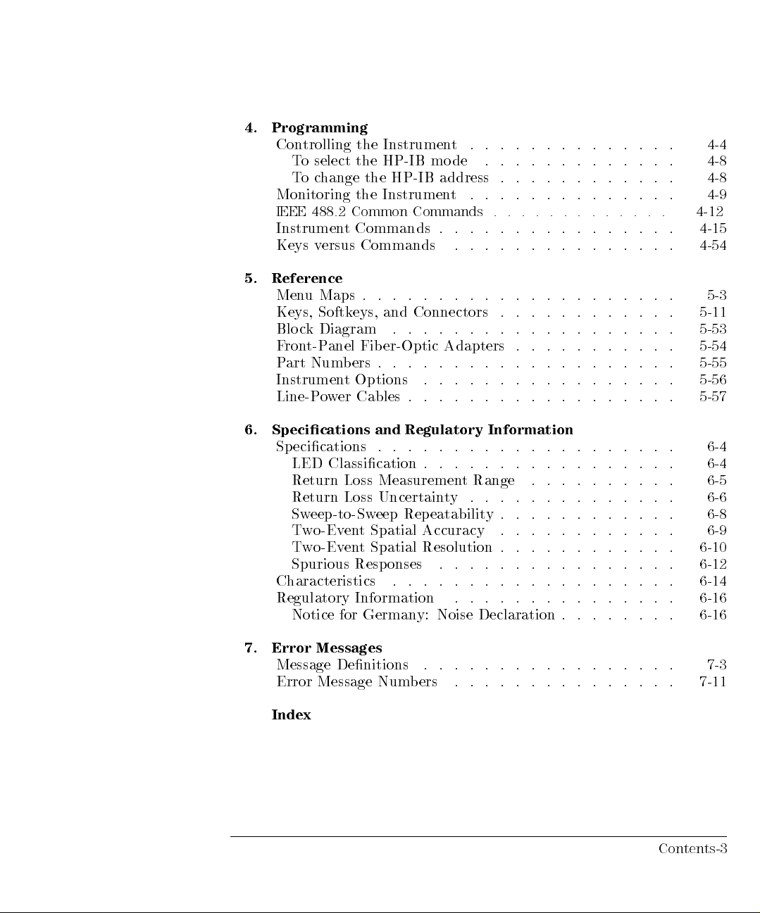
4. Programming
Controlling the Instrument . . . . . . . . . . . . . .
To select the HP-IB mode . . . . . . . . . . . . .
Tochange the HP-IB address . . . . . . . . . . . .
Monitoring the Instrument . . . . . . . . . . . . . .
IEEE 488.2 Common Commands . . . . . . . . . . . . . 4-12
Instrument Commands . . . . . . . . . . . . . . . .
Keys versus Commands . . . . . . . . . . . . . . .
5. Reference
MenuMaps . . . . . . . . . . . . . . . . . . . . .
Keys, Softkeys, and Connectors . . . . . . . . . . . .
. .
.
.
.
.
.
.
.
.
.
.
.
.
.
.
.
Diagram
ck
Blo
anel Fib
t-P
ron
F
Num
art
P
Instrumen
w
Line-P
o
b
t
er
.
er-Optic Adapters
. .
. .
ers
Options
Cables
.
. .
.
.
. .
.
. .
.
.
.
.
.
. .
. .
.
.
.
.
.
.
.
.
.
.
.
.
.
.
.
.
.
.
.
.
.
. .
.
.
.
.
.
.
.
.
.
.
.
.
4-4
4-8
4-8
4-9
4-15
4-54
5-3
5-11
.
5-53
5-54
.
.
5-55
.
.
5-56
.
.
5-57
.
.
.
.
y
. .
.
.
Range
t
.
.
.
.
. .
Information
.
.
.
.
.
.
.
.
.
.
.
.
.
.
.
.
.
.
y
. .
. .
. .
. .
. .
. .
.
.
.
.
.
.
. .
.
.
.
.
.
.
.
.
.
.
.
.
.
.
.
Specications
6.
ecications
Sp
LED
Return
Return Loss
Sweep-to-Sw
Tw
Tw
Spurious
and
Classication
Loss
Spatial
t
en
o-Ev
Spatial Resolution
t
en
o-Ev
Resp
Regulatory
.
.
.
.
.
.
.
Measuremen
Rep
t
eatabilit
Uncertain
eep
Accuracy
onses
.
Characteristics . . . . . . . . . . . . . . . . . . .
Regulatory Information . . . . . . . . . . . . . . .
Notice for Germany: Noise Declaration . . . . . . . .
7. Error Messages
Message
Message
Error
Denitions
Num
.
.
.
.
.
.
.
.
. .
.
ers
b
.
.
.
.
.
.
. .
.
.
.
Index
6-4
.
.
.
.
.
6-4
.
.
.
.
.
6-5
.
.
.
.
.
6-6
.
.
.
.
.
6-8
.
.
.
.
.
6-9
.
.
.
.
.
6-10
.
.
.
.
.
6-12
.
.
.
.
.
6-14
6-16
6-16
.
.
.
.
.
. .
.
.
.
7-3
7-11
Contents-3
Page 16

Contents
Page 17
1
Installing
Page 18
WA
RN
IN
Installing
This chapter shows you how to install your precision reectometer and how
to verify that it is operating properly. Be sure to save the shipping containers
in the event that the instrument should need to be returned to HP.Itis
important to have the correct packaging.
Refer to Chapter 6 for information on operating conditions such as
temperature.
If you should ever need to clean the cabinet, use a damp cloth only.
continued protection
G
For
same type
correct
The
and ratings
fuse types
against re
use of
. The
are listed
hazard, replace
fuses
other
rear
the
on
or
panel
line
materials
each
of
prohibited.
is
instrument
with
only
fuse
section.
N
I
N
R
A
W
ON
I
T
U
A
C
CAUTION
out
and
(outside
If
, then
for
to
of
of
the
forced
a
external
an
that
power
a cabinet,
in
the
watts
100
cabinet
via
common
its
supply
.
the
ambient temperature
maximum
dissipated
greater
is
G
If
voltage
neutral
When
product
the
cabinet)
the
product
the
power
total
reduction,
(earthed
installing
product
this
convection
is
pole)
the
not
must
be
must
4
by
C
dissipated
be
must
sure
make
the
of
product
restricted. The
be
than
less
every
for
the
in
used.
energized
be
to
autotransformer
terminal
convection
operating
the
in
800
than
connected
is
into
temperature
cabinet.
watts
This product is designed for use in INSTALLATION CATEGORY II and
POLLUTION DEGREE 2, per IEC 1010 and 664 respectively.
1-2
Page 19
Installing
Contents
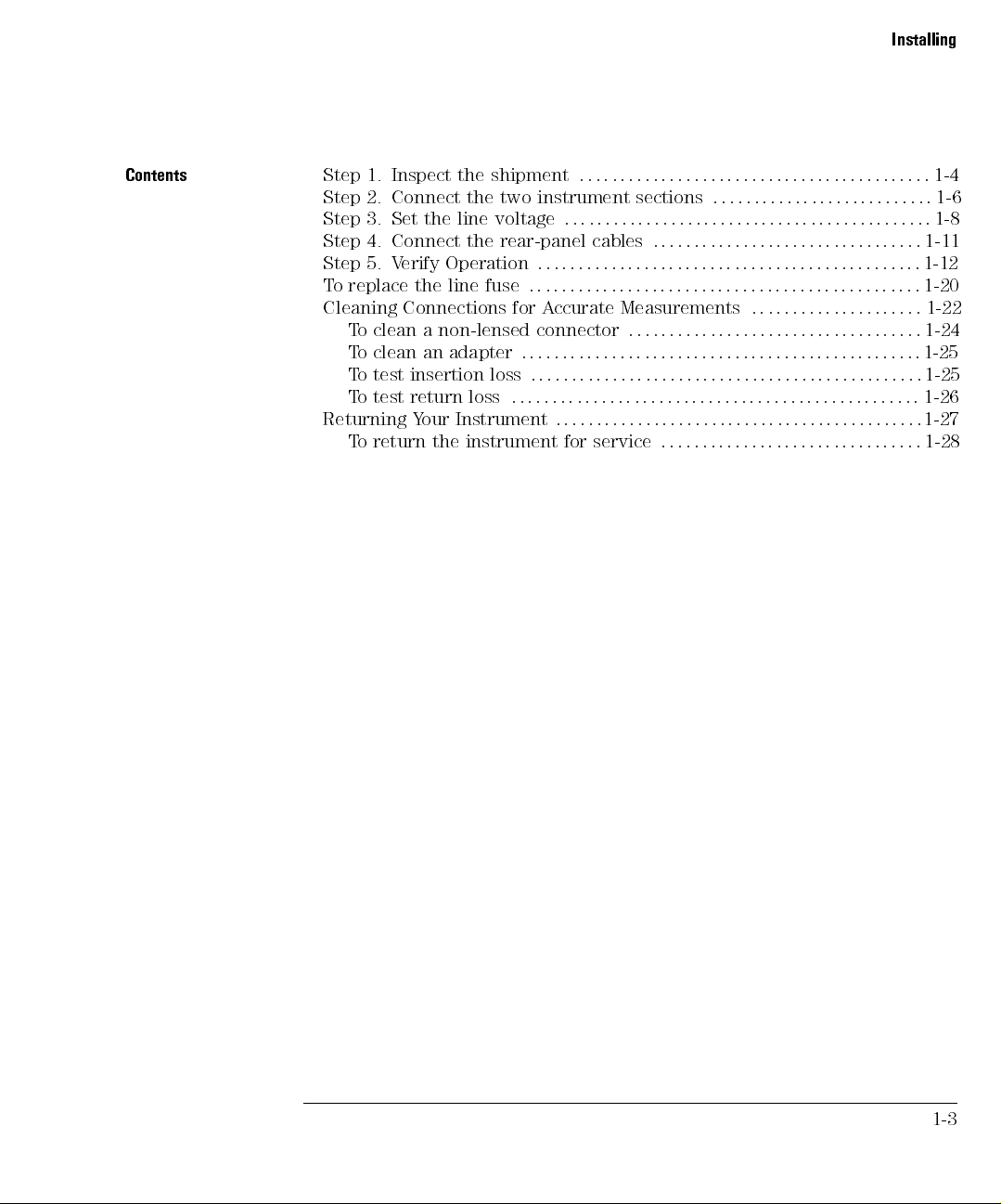
Step 1. Inspect the shipment
Step 2. Connect the two instrument sections
Step 3. Set the line voltage
Step 4. Connect the rear-panel cables
Step 5. Verify Operation
To replace the line fuse
:::::::::::::::::::::::::::::::::::::::::::
::::: ::::::: ::::::: :::::: ::
::::: ::::::: ::::::: :::::: ::::::: ::::::::: ::::
::::::: :::::: ::::::: ::::::: ::::::
:::::: ::::::: :::::: ::::::: ::::::: ::::::::: :::::
:::::: ::::::: :::::: ::::::: ::::::: ::::::::: ::::::
Cleaning Connections for Accurate Measurements
To clean a non-lensed connector
To clean an adapter
To test insertion loss
To test return loss
Instrument
our
return
o
Y
the
Returning
T
instrument
:::::::::::::::::::::::::::::::::::::::::::::::::
::::::::::::::::::::::::::::::::::::::::::::::::
:::::: :::::: ::::::: ::::::: :::::: ::::::::: :::::::::
:
:
:
for
::::: ::::::: :::::: ::::::: ::::::: ::::
:
:
:
:
:
:
:
:
:
:
:
:
:
:
:
:
:
:
:
:
:
:
:
:
:
service
:
:::::: ::::::: :::::: ::
:
:
:
:
:
:
:
:
:
:
:
:
:
:
:
:
:
:
:
:
:
:
:
:
::
::
::
::
:
:
1-4
1-6
1-8
1-11
1-12
1-20
1-22
1-24
1-25
1-25
1-26
1-27
:
:
:
:
:
:
:
1-28
:
:
:
:
:
:
:
1-3
Page 20
Step 1. Inspect the shipment
Verify that all system components ordered have arrived by comparing the
shipping forms to the original system purchase order. Inspect all shipping
containers.
If your shipment is damaged or incomplete, save the packing materials
and notify both the shipping carrier and the nearest Hewlett-Packard
sales and service oce. HP will arrange for repair or replacement of
damaged or incomplete shipments without waiting for a settlement from
transportation
the
problems
Notify
company
.
.
the
customer engineer
HP
of any
1-4
Page 21
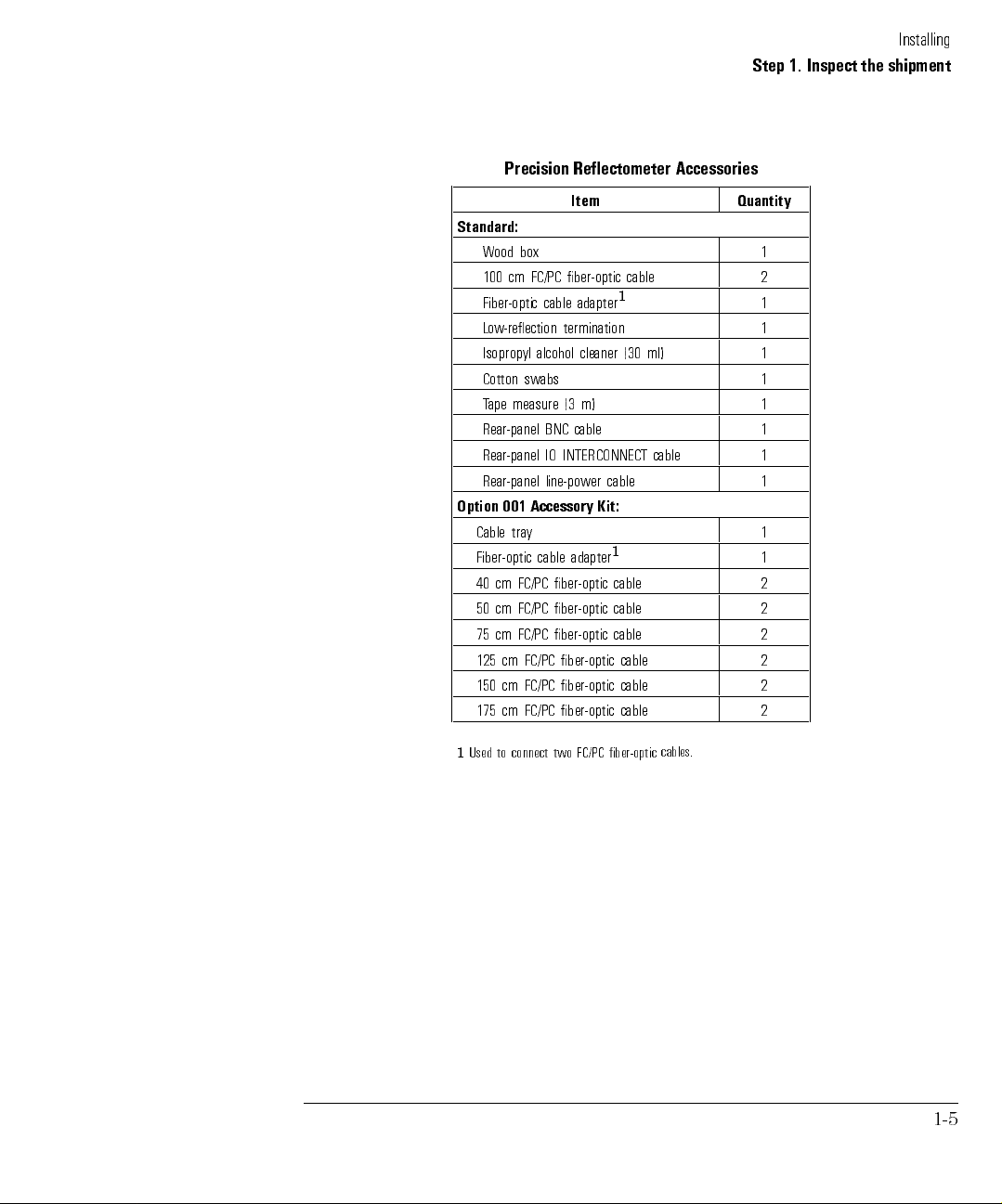
Precision Reectometer Accessories
Item Quantity
Standard:
Wood box 1
100 cm FC/PC ber-optic cable 2
Fiber-optic cable adapter
1
Low-reection termination 1
Isopropyl alcohol cleaner (30 ml) 1
Cotton swabs 1
Tape measure (3 m) 1
cable
001
tra
cm
cm
cm
cm
cm
cm
BNC
IO
Accessory
y
cable
ber-optic
FC/PC
ber-optic
FC/PC
ber-optic
FC/PC
FC/PC
FC/PC
FC/PC
INTERCONNEC
cable
Kit:
1
adapter
cable
cable
cable
ber-optic
cable
ber-optic cable
ber-optic
cable
cable
T
Rear-panel
Rear-panel
Rear-panel line-power
Option
Cable
Fiber-optic
40
50
75
125
150
175
Installing
Step 1. Inspect the shipment
1
1
1
1
1
1
2
2
2
2
2
2
cables.
ber-optic
FC/PC
two
connect
to
Used
1
1-5
Page 22
Step 2. Connect the two instrument sections
WARNING
Always disconnect and separate the two instrument sections before lifting
or moving the instrument. Otherwise, you may harm yourself or damage
the instrument.
1. Verify that serial number labels on the two instrument sections contain
the same serial number.You'll nd these labels on the precision
reectometer's rear panel. Make sure that the serial number and options
listed on the labels match the serial number and options listed on the
shipping document.
in)
so
.
in
that
front
the
of
the
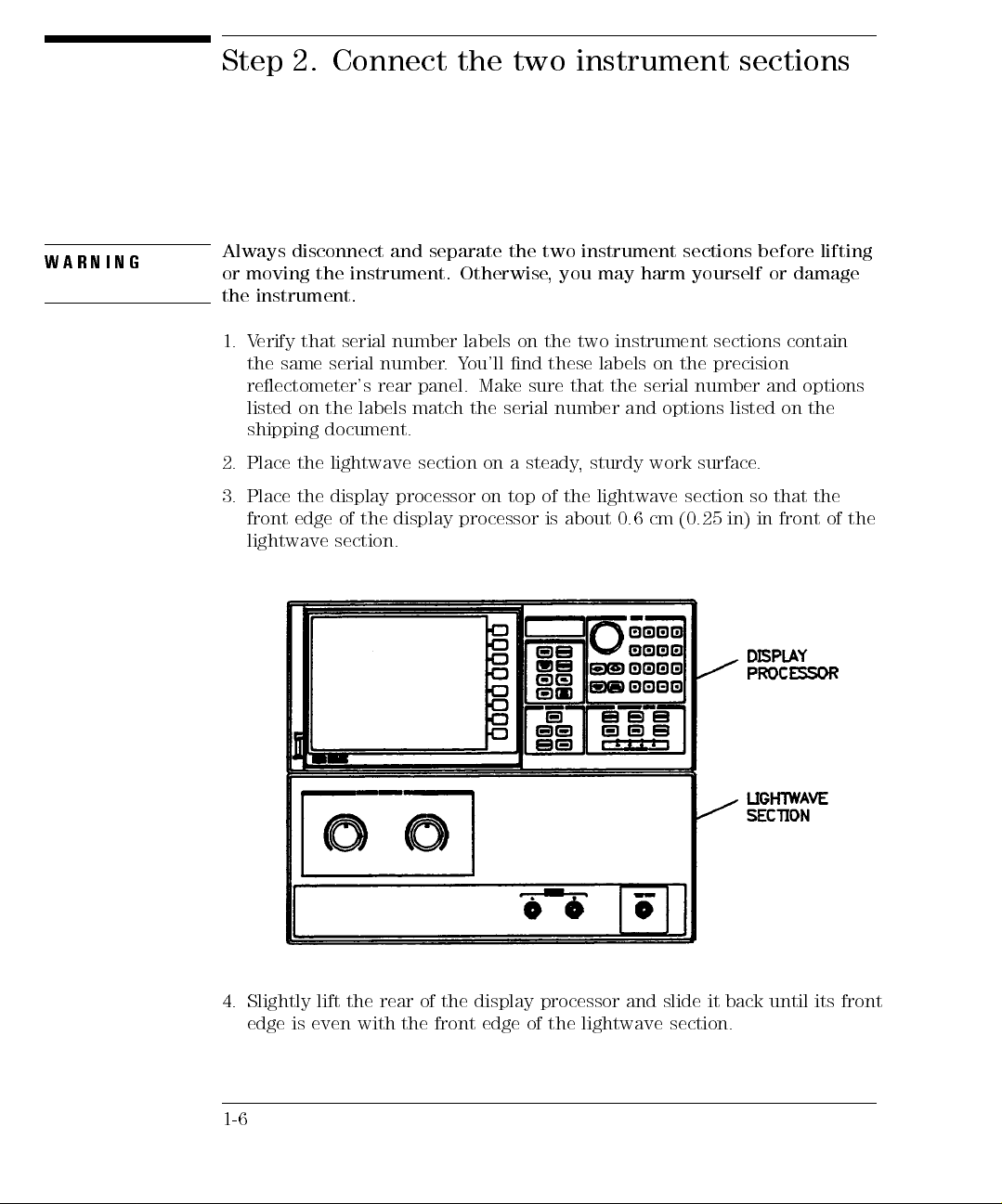
2. Place
Place
3.
front
lightwave
the lightwave
the display
of the
edge
section.
section on
processor on
a steady
top
display processor
of
is
sturdy
,
the
about
work
lightwave
cm
0.6
surface
section
(0.25
4. Slightly lift the rear of the display processor and slide it back until
edge is even with the front edge of the lightwave section.
1-6
its front
Page 23
Installing
Step 2. Connect the two instrument sections
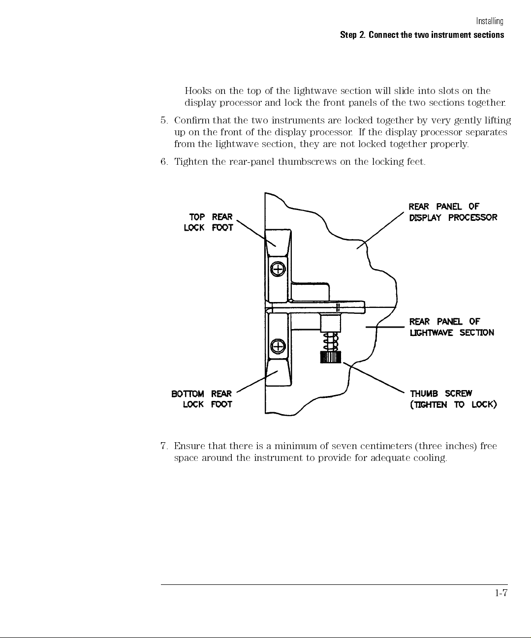
Hooks on the top of the lightwave section will slide into slots on the
display processor and lock the front panels of the two sections together.
5. Conrm that the two instruments are locked together by very gently lifting
up on the front of the display processor. If the display processor separates
from the lightwave section, they are not locked together properly.
6. Tighten the rear-panel thumbscrews on the locking feet.
7. Ensure that there is a minimum of seven centimeters (three inches) free
space around the instrument to provide for adequate cooling.
1-7
Page 24
Step 3. Set the line voltage
CAUTION
Severe damage to the instrument can result if line voltage settings are
incorrect when power is applied.
The line-power
.
Determine
1.
should
voltage
line
the
not
be connected to the precision reectometer at this time.
of
power
C
A
the
source
cords
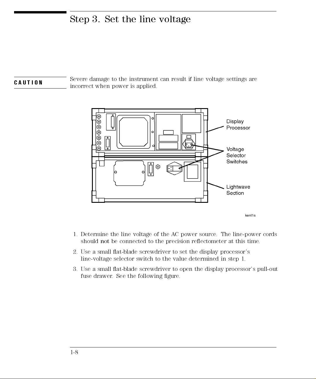
2. Use a small at-blade screwdriver to set the display processor's
line-voltage selector switch to the value determined in step 1.
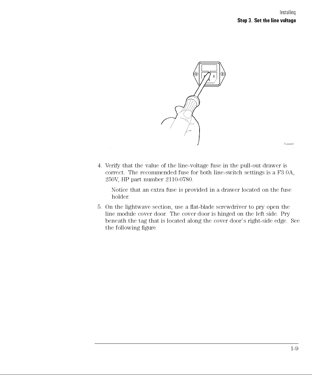
3. Use a small at-blade screwdriver to open the display processor's pull-out
fuse
drawer
following
the
See
.
gure.
1-8
Page 25
Installing
Step 3. Set the line voltage
V
4.
correct.
250V
On
5.
line
beneath
the
erify
,
Notice
holder
the
module
following
that the
The
part
HP
that
.
lightwave
cover
the
value of
the
recommended
extra
2110-0780.
fuse
number
an
section,
.
door
located
is
that
tag
gure
line-voltage
fuse
is provided
a
use
cover
The
along
fuse
both line-switch
for
a
in
at-blade
door
screwdriver
is
cover
the
hinged
the
in
drawer
door's
pull-out
settings
located
to
the
on
right-side
drawer
on
pry
left
a
is
the
open
side.
edge
is
F3.0A,
fuse
the
Pry
.
See
1-9
Page 26
Installing
Step 3. Set the line voltage
be
must
position,
in
and
voltage
rotate
N
O
I
T
U
A
C
Do
the
line
module
attempt
not
completely
to
or
removed
the
non-repairable
line
the
from
selector
damage
module
cam
will result.
rotated
,
to
The
the
cam
proper
installed
is
it
while
reinstalled.
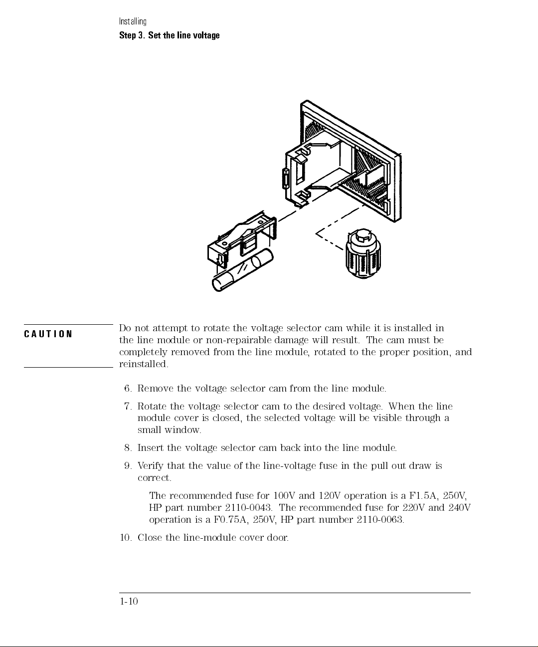
6. Remove
7. Rotate
the voltage
the voltage
selector
selector
cam
cam
to
from
the
line
the
desired
module
voltage
.
When
.
the
line
module cover is closed, the selected voltage will be visible through a
small window.
8. Insert the voltage selector cam back into the line module.
9. Verify that the value of the line-voltage fuse in the pull out draw is
correct.
recommended
The
fuse
for
100V
and
120V
operation
F1.5A, 250V
a
is
,
HP part number 2110-0043. The recommended fuse for 220V and 240V
operation is a F0.75A, 250V
10. Close the line-module cover door
, HP part number 2110-0063.
.
1-10
Page 27
Step 4. Connect the rear-panel cables
WARNING
N
O
I
T
U
A
C
This is a Safety Class 1 Product (provided with a protective earthing
ground incorporated in the power cord). The mains plug shall only be
inserted in a socket outlet provided with a protective earth contact.
Any interruption of the protective conductor inside or outside of the
instrument is likely to make the instrument dangerous. Intentional
interruption is prohibited.
Always use the three-prong AC power cord supplied with this instrument.
Failure
to ensure
instrument damage
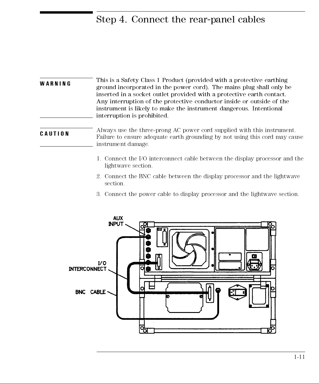
I/O
Connect
1.
lightwave
Connect
2.
the
section.
BNC
the
adequate earth
.
interconnect
between
cable
grounding
cable
the
by
between
display
display
the
processor
processor
the
and
and
lightwave
cause
may
cord
this
using
not
section.
Connect
3.
the
power
cable
to
display
processor
and
lightwave
the
section.
the
1-11
Page 28
Step 5. Verify Operation
This step takes approximately 20 minutes to complete.
Equipment Required
The following equipment is supplied with the precision reectometer.
Two 100 cm FC/PC ber-optic cables.
One ber-optic cable coupling adapter.
One low-reection ber-optic termination.
Tighten
connectors
Over-tightening
measurements.
sheet
data
Turn
1.
hour
one
Clean
2.
Refer to
for
the
all
properly
under-tightening
or
nger
ys
Alwa
torque
y
an
precision
connectors
connectors
tighten
recommendations.
reectometer
.
cable
connectors
and
\Cleaning Connections
in
result
can
consistent
a
in
and
on,
front-panel
ccurate
A
for
misalignment
manner
it
allow
optical
Measurements"
and
Refer
.
to
ports
warm
nonrepeatable
manufacturer's
the
to
for
up
.
for
information on cleaning connectors.
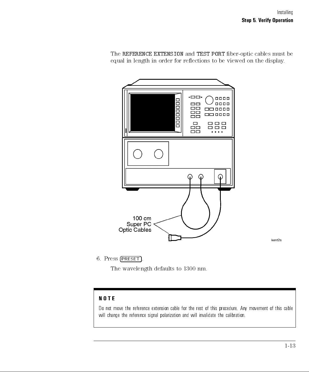
3. Attach one of the 100 cm ber-optic cables to the front-panel
TEST PORT
connector.
at
least
When mating Super PC connectors, check to see that the keyways on
inserted
PC cable
Super
the
connectors
there is a protective cap on the free end of the ber-optic cable
4. If
.
connectors
are
into
on
slots
the
it.
5. Attach the other 100 cm ber-optic cable between the front-panel
REFERENCE EXTENSION
connectorsAandB.
1-12
mating
the
, remove
Page 29
Installing
Step 5. Verify Operation
The
REFERENCE EXTENSION
equal in length in order for reections to be viewed on the display.
and
TEST PORT
ber-optic cables must be
6. Press
N
Do not move the reference extension cable for the rest of this procedure
will change the reference signal polarization and will invalidate the calibration.
4
PRESET
The wavelength defaults to 1300 nm.
OTE
5
.
y movement
.An
of this cable
1-13
Page 30
Installing
Step 5. Verify Operation
7. Press
4
CAL
5
and then
GUIDED CAL
.
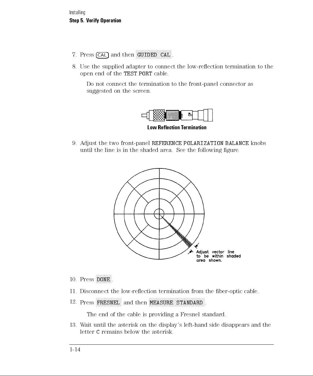
8. Use the supplied adapter to connect the low-reection termination to the
NNNNNNNNNNNNNNNNNNNNNNNNNNNNNNNN
open end of the
TEST PORT
cable.
Do not connect the termination to the front-panel connector as
suggested on the screen.
Low Reection Termination
9.
djust
A
until
the
the
two
line
front-panel
the
in
is
REFERENCE
shaded
area.
POLARIZATION
following
the
See
BALANCE
gure
knobs
.
10.
Disconnect
11.
12.
Press
The end of the cable is providing
.
DONE
the low-reection
NNNNNNNNNNNNNNNNNNNNN
NN
FRESNEL
and then
termination
NNNNNNNNNNNNNNNNNNNNN
NNNNNNNNNNNNNNNNNNNNNNNNN
from
MEASURE STANDARD
a Fresnel standard.
the
NNNN
.
ber-optic
cable
.
N
N
N
N
N
N
N
N
N
N
NN
N
N
Press
13. Wait until the asterisk on the display's left-hand side disappears and the
letterCremains below the asterisk.
1-14
Page 31
Installing
Step 5. Verify Operation
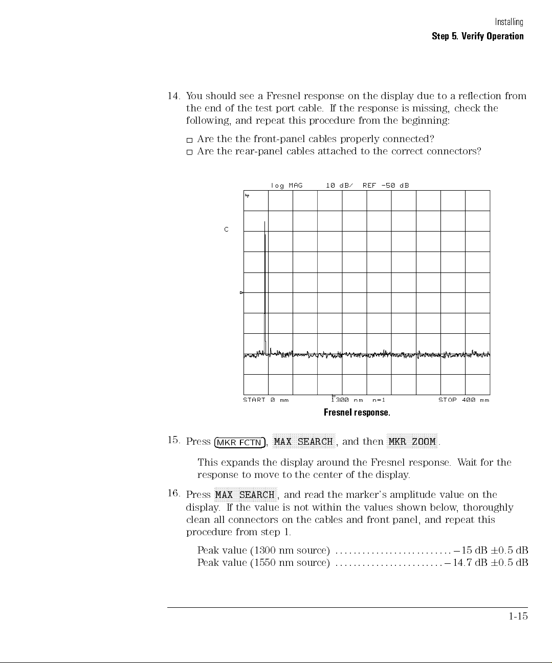
14. You should see a Fresnel response on the display due to a reection from
the end of the test port cable. If the response is missing, check the
following, and repeat this procedure from the beginning:
Are the the front-panel cables properly connected?
Are the rear-panel cables attached to the correct connectors?
response.
Fresnel
15.
Press
4
MKR FCTN
NNNNNNNNNNNNNNNNNNNNNNNNNNNNNNNN
5
,
MAX SEARCH
, and then
NNNNNNNNNNNNNNNNNNNNNNNNNN
MKR ZOOM
.
This expands the display around the Fresnel response.Wait for the
response to move to the center of the display.
NN
N
N
N
N
N
N
N
N
N
N
NN
N
N
N
N
N
N
N
N
N
N
N
NN
N
N
N
N
16.
N
Press
display
MAX
.
SEARCH
the
If
value
and
,
not within
is
read
the
the
values
marker's
clean all connectors on the cables and front
procedure
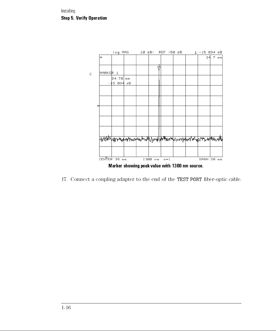
Peak value
Peak value (1550 nm
from step 1.
(1300 nm source)
source)
::::::: :::::: ::::::: ::
:::::: :::::: ::::::: :::::
amplitude
shown
value
below
panel, and repeat this
::::
on the
thoroughly
,
0
15 dB
0
14.7 dB
6
0.5 dB
6
0.5 dB
1-15
Page 32
Installing
Step 5. Verify Operation
17.
1-16
Connect
coupling
a
Marker showing
adapter to
peak
the
value
end
with
of
the
1300
TEST
nm
source.
PORT
ber-optic
cable
.
Page 33
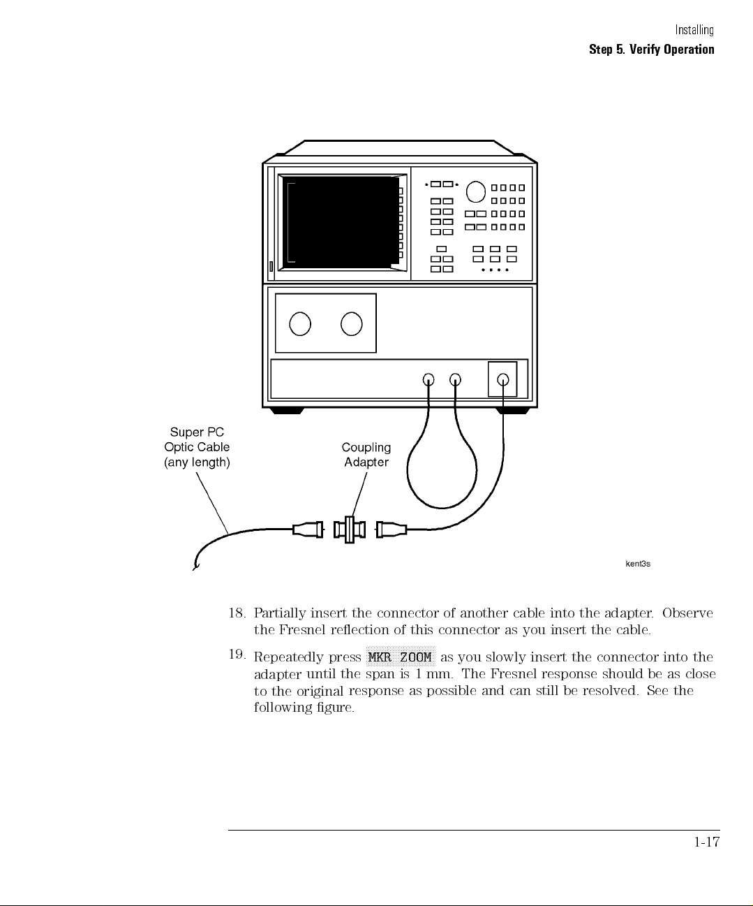
Installing
Step 5. Verify Operation
18. Partially insert the connector of another cable into the adapter. Observe
the Fresnel reection of this connector as you insert the cable.
19.
Repeatedly press
adapter
original
the
to
following gure
until
NNNNNNNNNNNNNNNNNNNNNNNNNN
MKR ZOOM
span
the
response
.
as you slowly insert the connector into the
resolved.
be
should
is
as
mm.
1
possible
The Fresnel
can still
and
response
be
See
as
close
the
1-17
Page 34
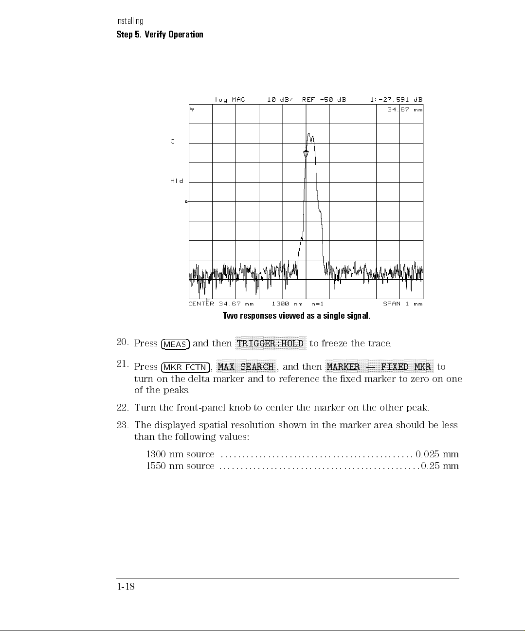
Installing
Step 5. Verify Operation
signal.
single
a
as
20.
21.
Press
Press
turn on
the
of
4
MEAS
4
MKR
the delta
peaks
5
F
.
and
CTN
T
then
N
N
N
N
,
5
MAX
marker
responses
wo
N
N
N
N
NN
N
N
TRIGGER:HOLD
N
N
N
N
NN
NN
N
N
N
N
N
N
SEARCH
and
N
N
N
N
N
N
N
N
N
N
N
N
N
N
N
N
N
N
N
N
N
N
to
viewed
N
N
N
N
NN
N
N
N
N
N
N
N
N
N
N
N
and
,
reference
N
N
N
N
N
then
to
freeze
N
N
N
N
N
N
N
N
N
MARKER
xed
the
NN
N
the
N
NN
N
trace
N
N
N
N
N
N
N
N
!
marker
N
N
N
N
N
N
.
N
N
NN
NN
N
N
N
N
N
FIXED
to
N
N
N
N
N
N
N
N
N
N
MKR
zero
N
N
N
N
N
N
N
to
one
on
22. Turn the front-panel knob to center the marker on the other peak.
23. The displayed spatial resolution shown in the marker area should be less
than the following values:
1300 nm source
source
nm
1550
:::::::::::::::::::::::::::::::::::::::::::::
:
:
:
:
:
:
:
:
:
::
:
:
:
:
:
:
:
:
:
:
::
:
:
:
:
:
:
:
:
:
:
:
::
:
:
:
:
:
:
:
0.025 mm
0.25
::
:
:
mm
1-18
Page 35
Installing
Step 5. Verify Operation
24.
25.
26.
4
Press
Press
PRESET
4
MENU
Remove
procedure
the
from
.
5
and then
5
coupling
step
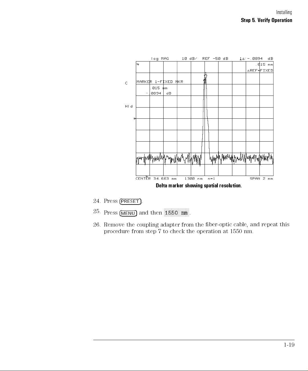
Delta
N
N
N
1550
adapter
to
7
marker
N
N
N
N
N
N
N
N
N
check
N
N
N
N
N
N
nm
from
showing
N
NN
N
N
.
the
the
spatial
ber-optic
operation
resolution.
cable
1550
at
,and
nm.
repeat this
1-19
Page 36
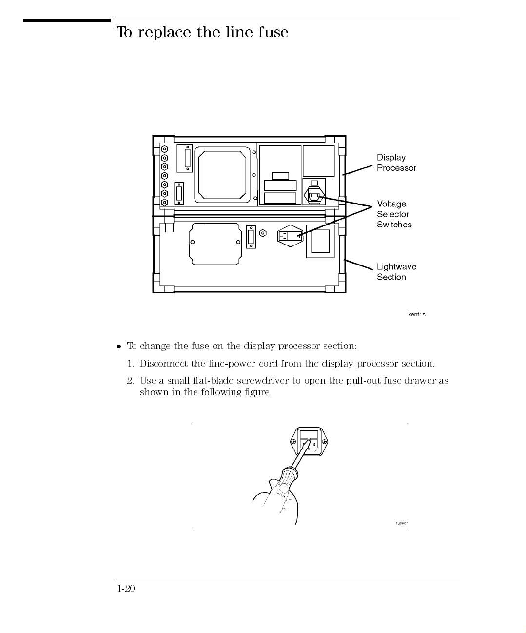
To replace the line fuse
T
1.
2.
1-20
o
change
the
Disconnect
small at-blade
Use a
shown
in the
the
on
fuse
line-power
the
screwdriver
following gure
display
cord
processor
from
to
.
the
open
section:
display
pull-out
the
processor
fuse
section.
drawer
as
Page 37
To replace the line fuse
3. The recommended fuse for both line-switch settings is a F3.0A, 250V,
HP part number 2110-0780.
Notice that an extra fuse is provided in a drawer located on the fuse
holder.
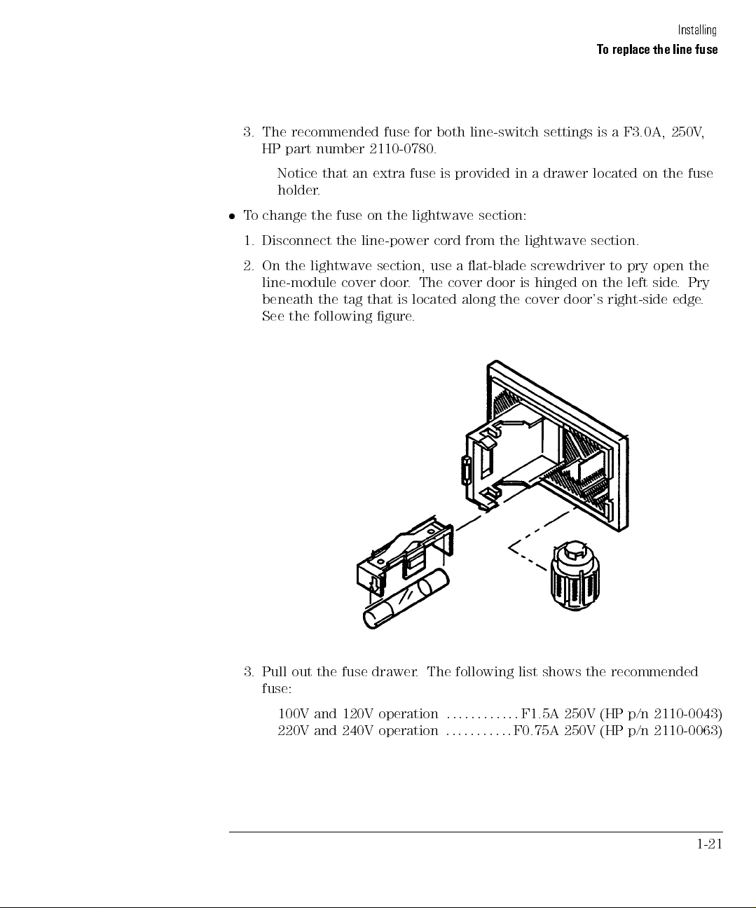
To change the fuse on the lightwave section:
1. Disconnect the line-power cord from the lightwave section.
2. On the lightwave section, use a at-blade screwdriver to pry open the
line-module cover door. The cover door is hinged on the left side. Pry
beneath the tag that is located along the cover door's right-side edge.
.
See
the
following
gure
Installing
the fuse
out
Pull
3.
fuse:
100V and 120V operation
220V and 240V operation
drawer
.
The
:
following
::::::: :::::
:::::: ::::
recommended
list
shows
the
F1.5A 250V (HP p/n 2110-0043)
F0.75A 250V (HP p/n 2110-0063)
1-21
Page 38
Cleaning Connections for Accurate
Measurements
Accurate and repeatable measurements require clean connections. Use the
following guidelines to achieve the best possible performance when making
measurements on a ber-optic system:
Keep connectors covered when not in use.
Use dry connections whenever possible.
Use the cleaning methods described in this section.
CAUTION
care in
Use
When
sure
or
Because
ensure
gaps
inserting a
that
adapter
of
good
damaged
,
the
.
the
connections
index-matching
connections
dry
Use
connections
Dry
Diamond
40
,
return
dB
(and can
ackard
example
has
improve
Hewlett-P
handling all
ber-optic
ber-optic connector
does
end
ber
cores
of
size
small
oor
P
.
contamination,
,
ends
ber
Dry
be
or
used
better
.
connectors
with
,
compounds
.
can
HMS-10/HP
loss
degrade) performance
strongly
recommends that
connectors
touch
not
in
used
connections
are
physically
FC/PC,
making
,
DIN,
into a
the
a
.
.
front-panel
outside
optical
result
and
easier
of the
bers
from
improper
clean
to
contacting
ST).
and
connection
wet
index matching
adapter
mating connector
care must
,
misalignment,
core
and
use
to
and
connectors
connection
dry
a
If
probably
will
compounds NOT
make
,
be
removal
keep
(for
used
of
clean.
not
be applied to their instruments and accessories. Some compounds,suchas
gels, may be dicult to remove and can contain damaging particulates.If
you think the use of such compounds is necessary, refer to the compound
manufacturer for information on application and cleaning procedures.
Cleaning
Accessories
Item HP Part Number
Isopropyl alcohol 8500-5344
Cotton swabs 8520-0023
Small foam swabs 9300-1223
Compressed dust remover (non-residue) 8500-5262
to
air
1-22
Page 39
Inspecting
Cables
Fiber-Optic
Consistent
indication
insertion
the
your
test
you
the
and
future
receipt,
in
Connector
lightwave
as
little
as
another
is
better
the
physically
although
Dust Caps Provided with Lightwave Instruments
measurements
have
you
that
and/or
loss
cables
the
retain
degradation
any
if
insertion)
(or
dB
.
of
connector
0.1
important
larger
(the
contacting
dB
40
to
30
Cleaning Connections for Accurate Measurements
Item HP Part Number
Laser shutter cap 08145-64521
FC/PC dust cap 08154-44102
Biconic dust cap 08154-44105
DIN dust cap 5040-9364
HMS10/HP dust cap 5040-9361
ST dust cap 5040-9366
lightwave
your
with
connections
good
of
is
values
It
.
return
common.
loss
for
data
occurred.
has
important
one
are
performance
a measure
is
, the
loss
have
return
accessories
and
measured
loss
Typical
with high
loss
factor
the
connectors
more
is
However
.
lightwave
your
insertion
comparison,
for
than
less
of
smaller the
return
equipment
you
,
cables
and
loss
you
performance
of
dB
1
connectors
reection:
reection).
better
losses
good
a
are
wish
may
accessories
or
be
loss
able
return
will
characteristic
and
,
loss
Return
.
reection
less
the
The
than 50
Installing
to know
.If
upon
tell
to
of
sometimes
loss
best
dB,
a
You can visually inspect your cables
Although it is not necessary, visual inspection of ber ends can be helpful. Contamination or
imperfections on the cable end face can be detected as well as cracks or chips in the ber itself. Use
a microscope (100X to 200X magnication) to inspect the entire end face for contamination, raised
metal,
Visible
keep
dents
or
imperfections
bers
the
in the
from
as
metal
touching
not
contacting).
well
the
as
ber
imperfections.
other
y
an
not
y
ma
core
Inspect
performance (unless
aect
imperfections
the
chips.
and
cracks
ber for
the
1-23
Page 40
Installing
Cleaning Connections for Accurate Measurements
To clean a non-lensed connector
CAUTION
Do not use any type of foam swab to clean optical ber ends.Foam swabs
can leave lmy deposits on ber ends that can degrade performance.
1. Apply isopropyl alcohol to a clean lint-free cotton swab or lens paper.
Cotton swabs can be used as long as no cotton bers remain on the ber
end after cleaning.
2. Before cleaning the ber end, clean the ferrules and other parts of the
connector
Apply
3.
Clean
4.
paper
Some
remove
them.
.
isopropyl
ber
the
and
back
amount
particles
This
alcohol
with
end
across
forth
wiping
of
when
technique
new
a
to
swab
the
the
mild
or
application
remove
can
clean lint-free
lens paper
or
several
end
ber
scrubbing
alcohol
of
displace
or
cotton swab
.Move
times.
ber
the
of
alone
particles
the
will
swab
end
not
smaller
or lens
or
help
can
remove
than
paper.
lens
micron.
Immediately
5.
lens
6. Blow
ltered, dry
ber
the
.
paper
across the
, compressed
end face
ber
the
dry
connector end
.
end
air.
a
with
face from
Aim the
clean,
dry
distance
a
compressed
lint-free
,
gas
of
6
at
cotton
to
a
swab
inches
8
shallow
using
angle
Nitrogen gas or compressed dust remover can also be used.
one
or
to
CAUTION
Do not shake,tip, or invert compressed air canisters, because this releases
particles in the can into the air. Refer to instructions provided on the
compressed
soon
As
7.
air
as
canister
the
.
connector
cover it
connect
,
dry
is
or
for
.
use
later
1-24
Page 41
Cleaning Connections for Accurate Measurements
To clean an adapter
1. Apply isopropyl alcohol to a clean foam swab.
Cotton swabs can be used as long as no cotton bers remain after
cleaning. The foam swabs listed in this section's introduction are small
enough to t into adapters.
Although foam swabs can leave lmy deposits, these deposits are very
thin, and the risk of other contamination buildup on the inside of
adapters greatly outweighs the risk of contamination by foam swabs.
.
swab
adapter
foam
with
clean,
a
dry
foam
,
swab
.
2. Clean
3. Dry
the adapter
the inside
with the
of the
Installing
be
air.
used.
this
on
releases
the
, compressed
ltered,
compressed
the
.
using
.
air
dust
Refer
adapter
,
the
air
the
or
gas
or
,
tip
can
canister
compressed
invert
into
through
Blow
4.
Nitrogen
N
O
I
T
U
A
C
Do
particles
in
shake
not
compressed
dry
also
remover
air
to
can
because
canisters
,
instructions provided
To test insertion loss
Use an appropriate lightwave source and a compatible lightwave receiver to
test insertion loss. Examples of test equipment congurations include the
following equipment:
Option
71451A
71450A
HP
built-in
HP 8702 or HP 8703 lightwave component analyzer system
HP 83420 lightwave test set with an HP 8510 network analyzer
HP 8153 lightwave multimeter with a source and power sensor module
or HP
white
light
source.
optical
spectrum
analyzers
with
002
1-25
Page 42
Installing
Cleaning Connections for Accurate Measurements
To test return loss
Use an appropriate lightwave source, alightwave receiver, and lightwave
coupler to test return loss. Examples of test equipment congurations include
the following equipment:
HP 8703 lightwave component analyzer
HP 8702 analyzer with the appropriate source, receiver, and lightwave
coupler
HP 8504 precision reectometer
8153 lightwave
HP
conjunction with
81554SM
HP
multimeter with
a lightwave
source
dual
and
coupler
81534A
HP
source
a
power
and
return loss
sensor
module
module
in
1-26
Page 43
Returning Your Instrument
It is unlikely that your precision reectometer should need to be returned
to the Hewlett Packard. However, if you do need to return it, repackage
the instrument using the original shipping containers and materials or their
equivalents. Hewlett-Packard oces can provide packaging materials identical
to the original materials.
CAUTION
Packaging materials not specied can result in instrument damage. Never
use styrene pellets to package electronic instruments. The pellets do not
adequately
and can
generate static
cushion
instrument,
the
electricity.
do
not
prevent
instrument
all
movement,
1-27
Page 44

Installing
Returning Your Instrument
To return the instrument for service
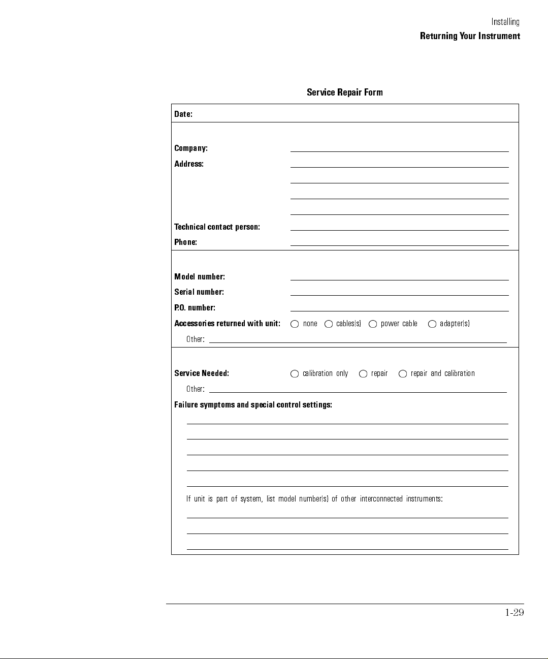
1. Fill out the repair form (located on the next page), and place it in the box
with the instrument. Send a copy of any noted error messages or other
helpful performance data.
2. To help prevent damage during transit, pack the instrument in the
factory packaging materials. Although the original shipping materials
or equivalents are best; the following instructions result in acceptable
packaging:
reduce
rap the
a. W
ESD damage
instruments
or
F
b.
double-walled,
strength.
accommodate
of
sides
Surround
c.
protect
to
packing
Sealed
from
plastic
Cap.
Air
provide
instrument in
.
weigh
that
corrugated
The
instrument
the
the
the
foam
Air
sheeting
Wrapping
carton
the
equipment
module
is
must
instrument.
for
and
available
not
Corporation,
with
lled
the instrument
sucient protection
anti-static
less
cardboard
both
be
Allow
packing
three
with
prevent
to
the
,
Hayward,
1-1/4
and also
plastic
than
best
inch
to
(120 lb),
54 kg
carton
large
at
of
enough
least
material.
inches
four
to
movement
alternative
California
bubbles
air
several
times
prevent movement
3. Seal the carton with strong nylon adhesive tape.
4. Mark the carton FRAGILE, HANDLE WITH CARE.
5. Retain copies of all shipping papers.
159
three
.
the
kg
and
to
of
the
in
is
94545.
Use
this
in
possibility
a
use
(350
strong
four
packing
carton.
.-240
.D
S
pink
material
in
lb) test
enough to
inches
material
If
Air
Cap
Air
anti-static
carton.
the
of
on all
TM
Cap
is
should
1-28
Page 45
Date:
Company:
Address:
Technical contact person:
Phone:
number:
Model
number:
Serial
number:
.
.O
P
Accessories
returned
with
Other:
unit:
Service Repair Form
cables(s)
none
power
Returning Your Instrument
adapter(s)
cable
Installing
Service
Other:
Failure
If
Needed:
symptoms
is
unit
part
and
of
special
system,
control
list model
number(s)
calibration
settings:
only
of
other
repair
interconnected
repair
instruments:
and
calibration
1-29
Page 46
Installing
Returning Your Instrument
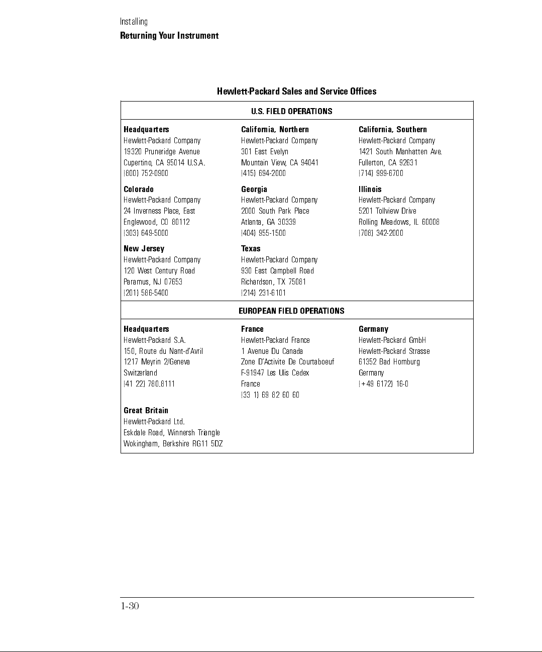
Hewlett-Packard Sales and Service Oces
U.S. FIELD OPERATIONS
Headquarters
Hewlett-Packard Company
19320 Pruneridge Avenue
Cupertino, CA 95014 U.S.A.
(800) 752-0900
Colorado
Hewlett-Packard Company
24 Inverness Place, East
Englewood, CO 80112
649-5000
(303)
Jersey
New
y
Compan
ackard
Hewlett-P
Road
Century
est
W
120
07653
NJ
aramus,
P
586-5400
(201)
Headquarters
S.A.
ackard
Hewlett-P
vril
Nant-d'A
Me
yrin
du
2/Geneva
150, Route
1217
Switzerland
780.8111
22)
(41
Britain
Great
Hewlett-Packard Ltd.
Eskdale Road, Winnersh Triangle
Wokingham, Berkshire RG11 5DZ
California, Northern
Hewlett-Packard Company
301 East Evelyn
Mountain View, CA 94041
(415) 694-2000
Georgia
Hewlett-Packard Company
2000 South Park Place
Atlanta, GA 30339
955-1500
(404)
exas
T
Compan
ackard
Hewlett-P
Road
Campbell
East
930
75081
Richardson,
(214)
EUROPEAN
TX
231-6101
FIELD
OPERA
France
France
ackard
Hewlett-P
Canada
Du
venue
1A
Courtaboeuf
De
D'Activite
Zone
Cedex
Ulis
es
L
F-91947
France
60
60
82
69
1)
(33
y
TIONS
California, Southern
Hewlett-Packard Company
1421 South Manhatten Ave.
Fullerton, CA 92631
(714) 999-6700
Illinois
Hewlett-Packard Company
5201 Tollview Drive
Rolling Meadows, IL 60008
342-2000
(708)
Germany
GmbH
ackard
Hewlett-P
Bad
y
Strasse
Homburg
16-0
Hewlett-Packard
61352
German
6172)
(+49
1-30
Page 47
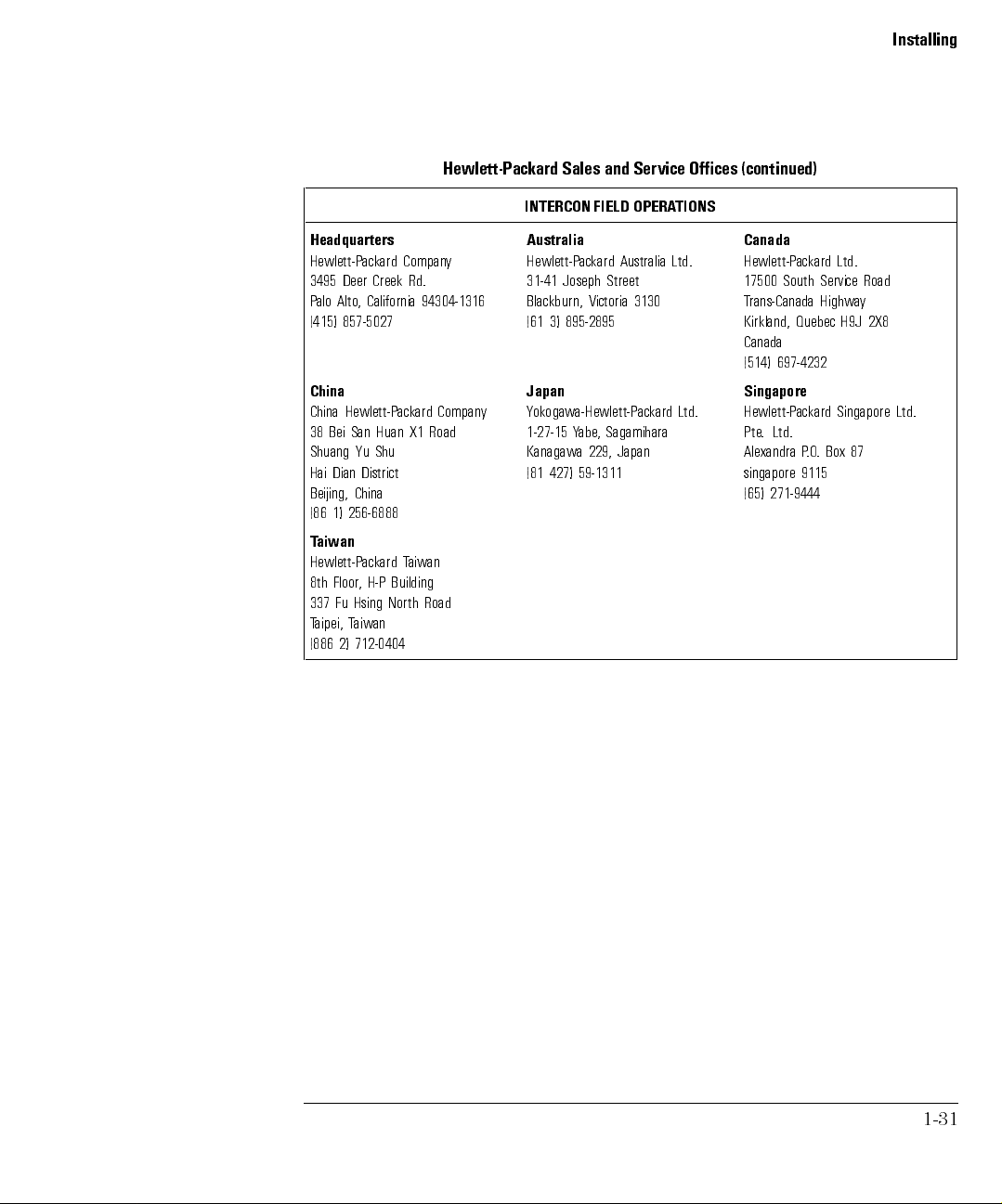
Hewlett-Packard Sales and Service Oces (continued)
INTERCON FIELD OPERATIONS
Installing
Headquarters
Hewlett-Packard Company
3495 Deer Creek Rd.
Palo Alto, California 94304-1316
(415) 857-5027
China
China Hewlett-Packard Company
Road
Huan X1
Bei San
38
Shu
u
Y
Shuang
District
Hai Dian
China
Beijing,
256-6888
1)
(86
aiwan
T
aiwan
T
ackard
Hewlett-P
Building
H-P
Floor,
8th
Road
North
Hsing
Fu
337
aiwan
T
aipei,
T
712-0404
2)
(886
Australia
Hewlett-Packard Australia Ltd.
31-41 Joseph Street
Blackburn, Victoria 3130
(61 3) 895-2895
Japan
Yokogawa-Hewlett-Packard Ltd.
, Sagamihara
Yabe
1-27-15
Japan
Kanagawa
(81 427)
229,
59-1311
Canada
Hewlett-Packard Ltd.
17500 South Service Road
Trans-Canada Highway
Kirkland, Quebec H9J 2X8
Canada
(514) 697-4232
Singapore
Hewlett-Packard Singapore Ltd.
. Ltd.
Pte
87
Box
.
.O
Alexandra
P
singapore 9115
271-9444
(65)
1-31
Page 48

Installing
Page 49
2
erforming
P
Guided
and Calibrations
Setups
Page 50
Performing Guided Setups and Calibra-
tions
This chapter shows you how to perform a
calibrations
, and manual calibrations. Calibrating the precision reectometer
guided setups,aguided
consists of balancing the receiver and then calibrating the magnitude. These
two procedures ensure maximum accuracy for your measurements. They
remove DC osets and polarization sensitivity. They also set a calibrated
reference level.
Guided setups not only calibrate the instrument, but they also select the
display
source
and
Manually calibrating
instructions
the instrument
both
for
is generally
pigtailed
non-pigtailed
and
faster that
using
devices
the
.
guided
calibration.
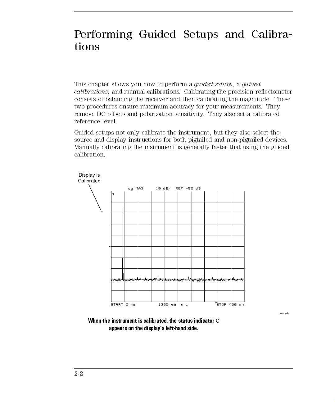
When the instrument is calibrated, the status indicator
appears on the display's left-hand side.
2-2
C
Page 51
Performing Guided Setups and Calibrations
Contents
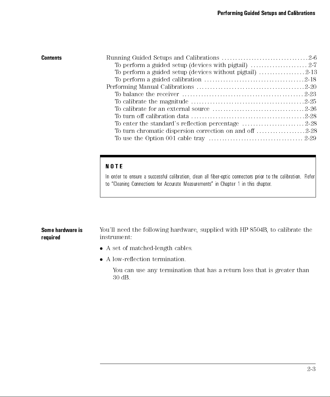
hardware
Some
required
Running Guided Setups and Calibrations
To perform a guided setup (devices with pigtail)
To perform a guided setup (devices without pigtail)
To perform a guided calibration
Performing Manual Calibrations
To balance the receiver
To calibrate the magnitude
::::: ::::::: :::::: ::::::: ::::::: ::::::::
:::::: ::::::: ::::::: :::::: ::::::: ::::::::: :::
::::::::::::::::::::::::::::::::::::::::::
To calibrate for an external source
To turn o calibration data
:::::: :::::: ::::::: ::::::: :::::: ::::::::: :
To enter the standard's reection percentage
To turn chromatic dispersion correction on and o
tray
cable
successful
for
001
calibration, clean
Accurate
Measurements"
, supplied
Option
the
use
o
T
E
T
O
N
a
ensure
to
order
In
need
Connections
following hardware
the
\Cleaning
to
ou'll
is
Y
:::::: ::::::: ::::::: :::::: ::::::
:::::: :::::: ::::::: ::
:::::: ::::::: ::::
:::::: ::::::: ::::::: :::::: ::::::: ::::
:::::: :::::: ::::::: ::::::: :::::: ::
:::::: ::::::: ::::::: :::
:::::: ::::::: :::::
:
:
:
:
:
:
:
:
:
:
:
:
:
:
:
:
:
:
:
:
:
:
:
:
:
:
:
:
:
:
:
:
:
:
calibration.
the
to
1in
HP
prior
this
8504B
chapter
,
.
calibrate
to
all ber-optic
Chapter
in
connectors
with
:
the
2-6
2-7
2-13
2-18
2-20
2-23
2-25
2-26
2-28
2-28
2-28
2-29
Refer
instrument:
matched-length cables
set of
A
A low-reection termination.
.
You can use any termination that has a return loss that is greater than
30 dB.
2-3
Page 52

Performing Guided Setups and Calibrations
Matched-length cables
ensure response is
visible
During calibrations and subsequent measurements, two cables must be
connected to the precision reectometer. One cable connects the device
being measured to the front-panel
front-panel
EXTENSION
PORT
The relative lengths of these two cables determine the position of the Fresnel
reection (from the end of the
REFERENCE EXTENSION
may not be visible on the screen. This is shown in the following gure.
REFERENCE EXTENSION A
cable must be equal in length (or slightly shorter) than the
cable.
cable is too long or too short, the measured response
TEST PORT
andBconnectors. The
TEST PORT
. The other cable connects the
REFERENCE
TEST
cable) on the screen. If the
2-4
lengths determine response position.
Cable
Page 53
Performing Guided Setups and Calibrations
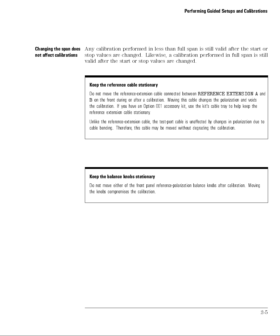
Changing the span does
not aect calibrations
Any calibration performed in less than full span is still valid after the start or
stop values are changed. Likewise, a calibration performed in full span is still
valid after the start or stop values are changed.
Keep the reference cable stationary
Do not move the reference-extension cable connected between
B
on the front during or after a calibration. Moving this cable changes the polarization and voids
REFERENCE EXTENSION A
and
the calibration. If you have an Option 001 accessory kit, use the kit's cable tray to help keep the
reference extension cable stationary.
to
Unlike the
reference-extension cable
cable bending.
balance
the
eep
K
move
not
Do
compromises
knobs
the
Therefore,
knobs
either
of
this
stationary
front
the
calibration.
the
the
,
y
ma
cable
reference-polarization
panel
test-port
moved
be
cable
without
unaected
is
degrading
balance
y
b
the
knobs
changes
calibration.
after
polarization
in
calibration.
due
Moving
2-5
Page 54
Running Guided Setups and Calibrations
This section shows you how to perform
guided setups
for pigtailed or
nonpigtailed devices. (A pigtail is a length of ber-optic cable which usually
terminates in a connector.) Guided setups can be started using either the
4
PRESET
5or4
SYSTEM
5
keys. Using the
4
PRESET
5
key has the advantage of
setting the instrument to a known state.
During a
guided calibration
, a polar vector display shows polarization
balance between two receivers in the instrument. After manually adjusting
precision
the
,
polarization
the
balance
using
reectometer mathematically
between the
complete
calibrate
specied
the
the
for
TEST PORT
calibration, a
magnitude.
standard
the
cable and
The displayed
in
front-panel
the
compensates for
the
REFERENCE
standard cable
percentage
knobs
any polarization
known
of
response
reectance
of
EXTENSION
reectance
scaled
is
.
to
match
imbalance
T
.
paths
used
is
the
o
to
value
2-6
Page 55
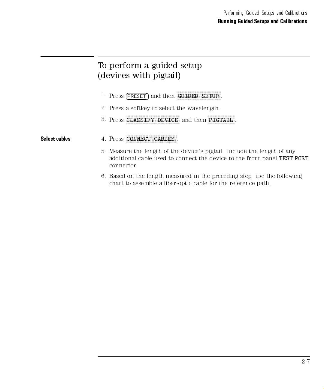
To perform a guided setup
(devices with pigtail)
Performing Guided Setups and Calibrations
Running Guided Setups and Calibrations
Select
cables
1.
Press
4
PRESET
5
and then
NNNNNNNNNNNNNNNNNNNNNNNNNNNNNNNNNNNNNN
GUIDED SETUP
2. Press a softkey to select the wavelength.
3.
NNNNNNNNNNNNNNNNNNNNNNNNNNNNNNNNNNNNNNNNNNNNNNN
Press
CLASSIFY DEVICE
and then
NNNNNNNNNNNNNNNNNNNNNNN
PIGTAIL
NNNNNNNNNNNNNNNNNNNNNNNNNNNNNNNNNNNNNNNNNNNN
Press
4.
Measure
5.
additional
connector
Based
6.
chart
CONNECT
the
cable
.
the
on
assemble
to
CABLES
length of
used
length
.
the device's
connect
to
measured
ber-optic
a
pigtail. Include
the device
preceding
the
in
for
cable
.
the
.
front-panel
to the
step
reference
the length
the
use
,
path.
any
of
PORT
TEST
following
2-7
Page 56
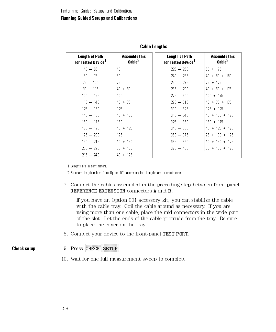
Performing Guided Setups and Calibrations
Running Guided Setups and Calibrations
Cable Lengths
Length of Path
for Tested Device
engths
L
1
Standard
2
Connect
7.
REFERENCE
If
with the
1
40 | 65 40
50 | 75 50
75 | 100 75
90 | 115 40 + 50
100 | 125 100
115 | 140 40 + 75
125 | 150 125
140 | 165 40 + 100
175
|
150
190
|
165
200
|
175
215
|
190
225
|
200
240
|
215
centimeters.
in
are
from
cables
length
cables
the
EXTENSION
an
have
you
cable tray
Assemble this
150
+
40
175
+
40
+
50
+
40
001
Option
assembled
Option
.Coil
2
Cable
125
150
150
175
L
kit.
accessory
in
connectors
accessory
001
cable
the
engths
the
A
Length of Path
for Tested Device
1
225 | 250 50 + 175
240 | 265 40 + 50 + 150
250 | 275 75 + 175
265 | 290 40 + 50 + 175
275 | 300 100 + 175
290 | 315 40 + 75 + 175
300 | 325 175 + 125
315 | 340 40 + 100 + 175
350
|
325
365
|
340
375
|
350
390
|
365
400
|
375
centimeters.
in
are
between
B
.
you
step
can
necessary
as
stabilize
preceding
and
kit,
around
150
40
75
40
50
If
.
using more than one cable, place the mid-connectors in the wide part
of the slot. Let the ends of the cable protrude from the tray.Besure
to place the cover on the tray.
Assemble this
+
+
+
+
+
Cable
175
125
100
150
150
2
175
+
175
+
175
+
175
+
front-panel
cable
the
are
you
Check
setup
8. Connect your device to the front-panel
9.
Press
N
N
NN
N
N
N
N
N
N
N
CHECK
N
N
N
N
N
N
N
N
N
N
N
N
NN
N
N
N
SETUP
NN
N
N
N
N
N
.
10. W
2-8
TEST PORT
complete.
.
Page 57
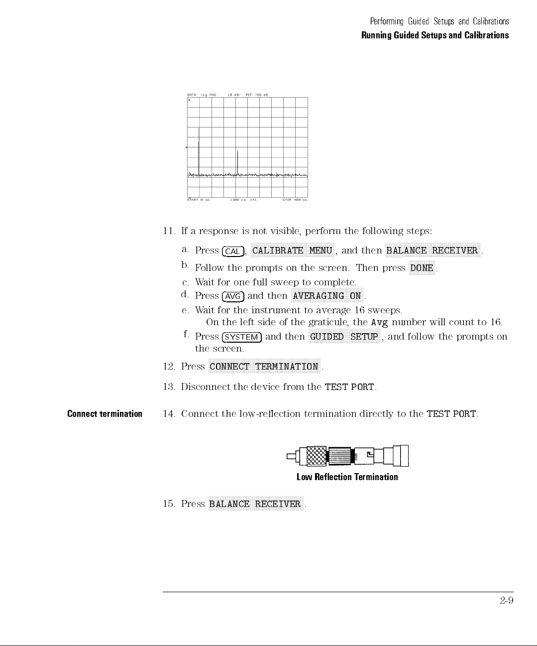
Performing Guided Setups and Calibrations
Running Guided Setups and Calibrations
Connect termination
NN
N
N
N
N
N
N
N
BALANCE
press
.
number
N
N
and
,
steps:
N
NN
NN
NN
NN
NN
DONE
follow
following
perform
,
visible
not
4
CAL
the
one
for
4
G
V
A
the
for
the
4
SYSTEM
screen.
N
N
N
N
N
NN
NN
N
N
N
N
the
N
N
N
N
N
N
N
N
N
N
N
NN
is
NN
NN
NN
N
N
N
N
N
N
N
,
5
CALIBRATE
prompts
sweep
full
then
and
5
instrument
side
left
and
5
NN
NN
N
N
N
N
N
N
N
N
N
N
N
N
N
N
N
N
TERMINATION
device from
N
N
N
N
N
N
NN
N
N
N
N
N
N
N
N
N
N
NN
N
N
N
N
N
N
N
N
N
N
N
N
NN
on the
N
N
N
N
N
N
AVERAGING
the
of
then
N
N
N
N
N
N
N
N
N
N
N
N
N
N
Low
N
N
N
N
N
N
N
NN
N
N
N
N
N
NN
N
N
N
N
N
MENU
complete
to
N
N
N
N
N
N
N
to
graticule
N
N
N
N
GUIDED
N
N
N
N
N
N
N
the
Reection
N
.
response
a
If
11.
a.
Press
b.
ollow
F
Wait
c.
d.
Press
ait
W
e.
On
f.
Press
the
N
N
Press
12.
13.
14. Connect the low-reection termination directly to the
15. Press
CONNECT
Disconnect
N
N
BALANCE RECEIVER
the
N
N
N
N
NN
NN
NN
screen. Then
N
N
N
N
N
N
N
N
N
average
N
N
N
N
N
N
N
N
N
NN
.
TEST
and
,
N
N
NN
NN
N
N
N
N
NN
N
N
then
.
N
N
N
N
N
N
N
N
N
.
ON
16
the
,
N
N
N
N
N
N
N
N
N
N
N
SETUP
PORT
Termination
sweeps
Avg
N
N
N
N
N
N
.
N
N
N
N
N
N
N
N
N
N
N
N
N
N
N
N
RECEIVER
N
N
N
N
N
N
N
N
N
N
.
will
the
TEST PORT
N
N
N
NN
NN
NN
NN
count
prompts
N
N
N
N
N
N
N
.
16.
to
on
.
2-9
Page 58
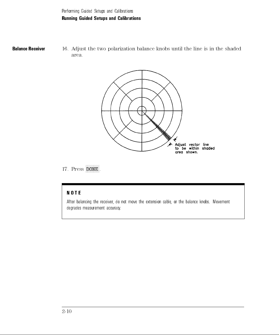
Performing Guided Setups and Calibrations
Running Guided Setups and Calibrations
Balance Receiver
16. Adjust the two polarization balance knobs until the line is in the shaded
area.
N
N
N
N
NN
N
N
N
N
N
N
N
N
Press
17.
E
T
O
N
DONE
.
After
degrades
2-10
balancing
measurement
the
receiver
accurac
extension
the
move
not
do
,
.
y
cable
balance knobs.
the
or
,
Movement
Page 59
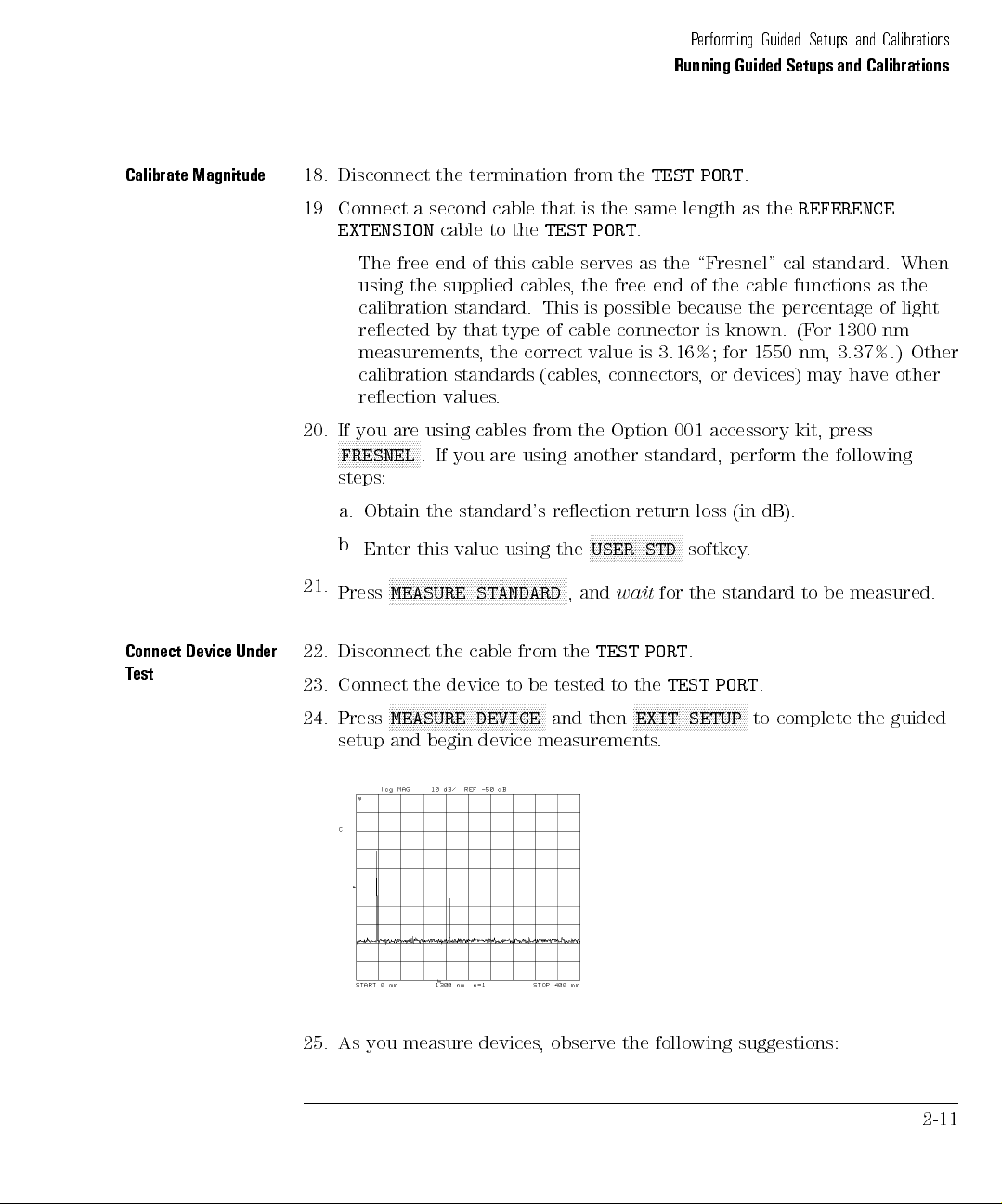
Performing Guided Setups and Calibrations
Running Guided Setups and Calibrations
Calibrate Magnitude
Under
Connect
T
Device
est
18. Disconnect the termination from the
19. Connect a second cable that is the same length as the
EXTENSION
cable to the
TEST PORT
TEST PORT
.
.
REFERENCE
The free end of this cable serves as the \Fresnel" cal standard. When
using the supplied cables, the free end of the cable functions as the
calibration standard. This is possible because the percentage of light
reected by that type of cable connector is known. (For 1300 nm
measurements, the correct value is 3.16%; for 1550 nm, 3.37%.) Other
calibration standards (cables, connectors, or devices) may have other
reection values.
press
20.
are
you
If
NN
N
N
N
N
N
N
N
N
N
N
N
N
N
N
N
FRESNEL
NN
NN
NN
using
If
.
you
cables
are
from
using
Option
the
another
001
standard,
accessory
perform
kit,
the
steps:
dB).
(in
N
N
N
N
N
STD
for
PORT
NN
N
N
N
N
N
.
N
N
N
N
N
TEST
N
N
N
N
N
NN
loss
softkey
standard
the
.
PORT
N
N
N
N
N
N
N
N
N
N
N
N
N
SETUP
.
N
N
N
to
.
complete
be measured.
to
a.
b.
21.
Press
Disconnect
22.
Connect
23.
Press
24.
setup
Obtain
Enter
N
N
N
N
N
MEASURE
N
N
N
N
N
MEASURE
and begin
N
NN
the
NN
N
N
the
this
N
N
N
NN
standard's
using
value
N
N
N
N
N
N
N
N
N
N
N
N
NN
N
N
N
N
N
N
N
N
N
N
N
N
N
N
N
N
N
N
N
STANDARD
from
cable
the
be
N
N
N
N
N
N
device
N
to
N
N
N
N
N
N
N
N
NN
NN
N
N
N
N
N
N
N
N
N
N
N
N
N
N
DEVICE
device measurements
reection
N
N
N
N
the
USER
N
N
N
N
N
N
and
,
TEST
the
tested
then
and
N
N
N
N
to
return
NN
N
N
N
N
wait
the
N
N
EXIT
NN
following
guided
the
25. As you measure devices
, observe the following suggestions:
2-11
Page 60
Performing Guided Setups and Calibrations
Running Guided Setups and Calibrations
Use the
4
START
5
and
4
STOP
5,4
CENTER
5
and
4
5
, and marker keys to
SPAN
optimize the displayed response.
Reducing the span increases measurement speed, improve
resolution, and increase dynamic range.
To improve the signal-to-noise ratio, use averaging. Turn on averaging
by pressing
4
AVG
5
and then
NNNNNNNNNNNNNNNNNNNNNNNNNNNNNNNNNNNNNNNNNNNNNNNNNN
AVERAGING on OFF
so that
highlighted.
NNNNNNNN
ON
is
2-12
Page 61
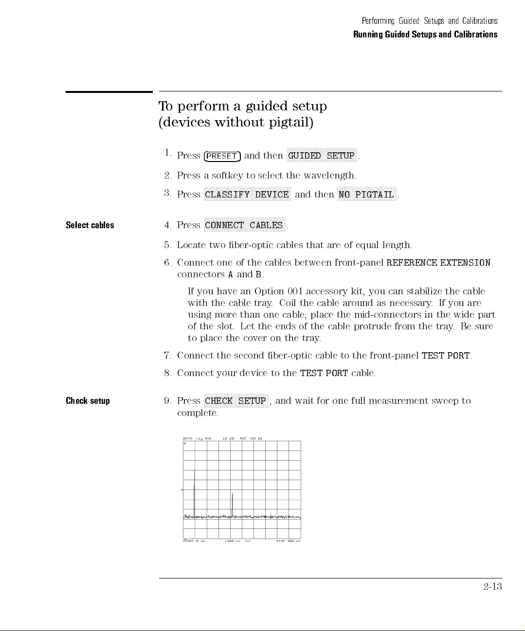
To perform a guided setup
(devices without pigtail)
Performing Guided Setups and Calibrations
Running Guided Setups and Calibrations
Select
Check
cables
setup
1.
Press
4
PRESET
5
and then
NNNNNNNNNNNNNNNNNNNNNNNNNNNNNNNNNNNNNN
GUIDED SETUP
2. Press a softkey to select the wavelength.
3.
NNNNNNNNNNNNNNNNNNNNNNNNNNNNNNNNNNNNNNNNNNNNNNN
Press
CLASSIFY DEVICE
and then
NNNNNNNNNNNNNNNNNNNNNNNNNNNNNNNN
NO PIGTAIL
NNNNNNNNNNNNNNNNNNNNNNNNNNNNNNNNNNNNNNNNNNNN
Press
4.
5.
6.
CONNECT
Locate
Connect
connectors
you
If
with
using
the
of
place
to
7. Connect
8. Connect
N
N
Press
9.
CHECK
CABLES
ber-optic cables
two
the
of
one
and
A
an
have
tray
cable
the
than
more
Let
slot.
cover
the
second
the
device
your
N
N
N
N
N
N
N
N
N
N
N
N
N
NN
NN
NN
NN
N
N
N
N
N
SETUP
B
Option
N
.
that are
cables between
.
accessory
001
the
Coil
.
place
,
cable
one
the
of
ends
the
tray
the
on
ber-optic
TEST
the
to
N
NN
N
N
N
,
and
wait
front-panel
cable
cable
.
cable
PORT
one
for
of equal
around
the
to
complete.
.
.
length.
REFERENCE
can
you
kit,
necessary
as
mid-connectors
protrude
the
cable
full
from
front-panel
.
measurement
stabilize
.
in
the
TEST
sweep
EXTENSION
cable
the
are
you
If
wide
the
Be
.
tray
.
PORT
to
part
sure
2-13
Page 62
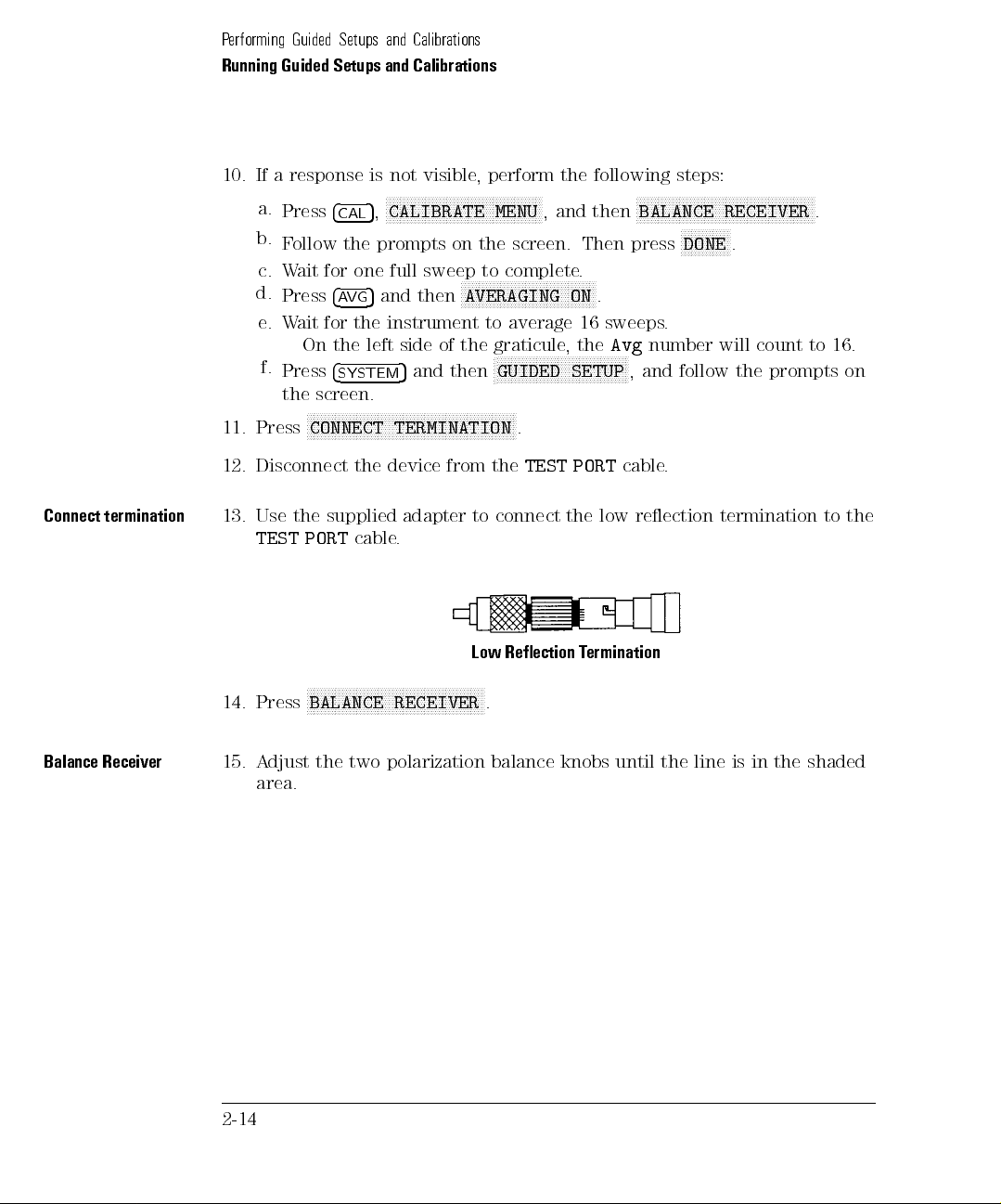
Connect
termination
Performing Guided Setups and Calibrations
Running Guided Setups and Calibrations
10. If a response is not visible, perform the following steps:
N
a.
Press
4
b.
Follow the prompts on the screen. Then press
c. Wait for one full sweep to complete.
d.
Press
4
NNNNNNNNNNNNNNNNNNNNNNNNNNNNNNNNNNNNNNNNNNN
5
,
CALIBRATE MENU
CAL
5
and then
AVG
, and then
NNNNNNNNNNNNNNNNNNNNNNNNNNNNNNNNNNNNNN
AVERAGING ON
N
NNNNNNNNNNNNNNNNNNNNNNNNNNNNNNNNNNNNNNNNNNNNNNNNN
BALANCE RECEIVER
NNNNNNNNNNNNNN
DONE
.
e. Wait for the instrument to average 16 sweeps.
On the left side of the graticule,the
f.
Press
4
SYSTEM
5
and then
NNNNNNNNNNNNNNNNNNNNNNNNNNNNNNNNNNNNN
N
GUIDED SETUP
Avg
number will count to 16.
, and follow the prompts on
the screen.
NNNNNNNNNNNNNNNNNNNNNNNNNNNNNNNNNNNNNNNNNNNNNNNNNNNNNNNNNNN
Press
11.
Disconnect
12.
Use
13.
TEST
CONNECT
supplied
the
PORT
TERMINATION
device
the
adapter
.
cable
from
.
TEST
the
connect the
to
cable
PORT
low reection
.
.
termination
.
the
to
Balance
Receiver
14.
15. A
2-14
Press
djust the
area.
N
N
N
N
N
N
N
N
N
N
N
N
N
N
N
NN
NN
N
N
N
N
BALANCE
two polarization
N
N
N
N
N
N
N
N
N
NN
NN
N
N
N
N
N
N
RECEIVER
N
N
N
N
Low
N
N
N
N
.
balance
Reection
ermination
T
knobs
until
the
line
shaded
the
in
is
Page 63
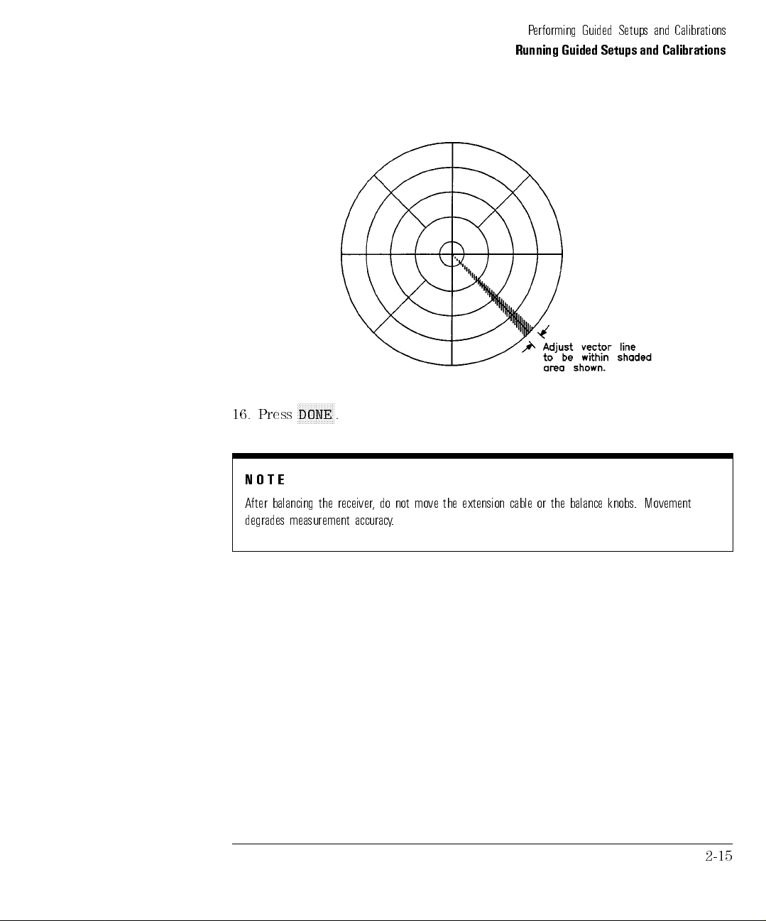
16.
Press
N
N
N
N
N
N
N
N
DONE
Performing Guided Setups and Calibrations
Running Guided Setups and Calibrations
N
N
N
N
N
N
.
T
O
N
balancing
After
degrades
E
measurement
the
receiver
accurac
the extension
move
not
do
,
.
y
cable or
Movement
knobs.
balance
the
2-15
Page 64
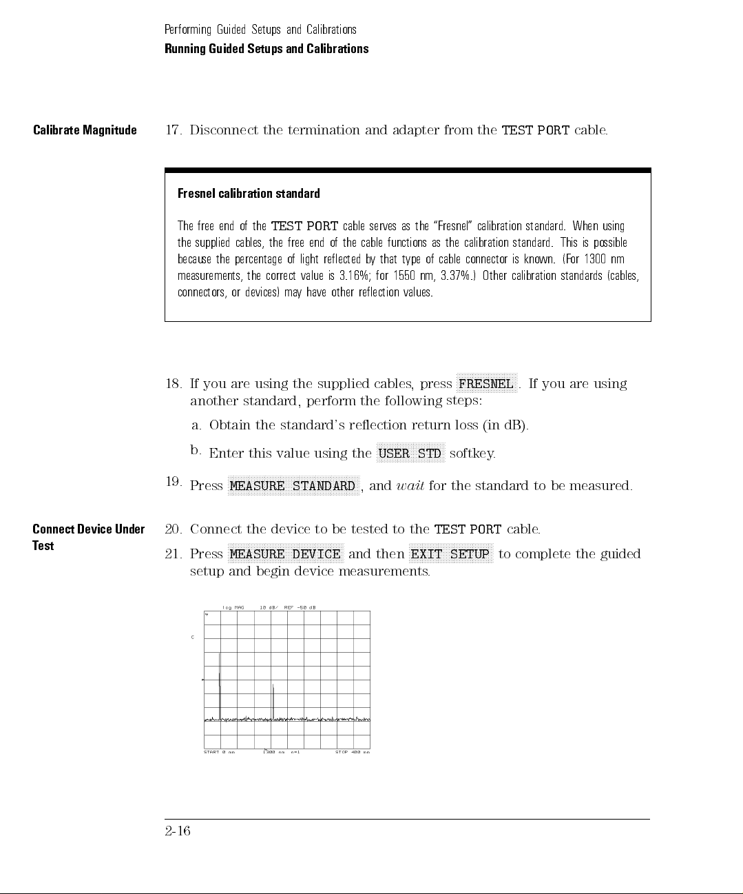
Performing Guided Setups and Calibrations
Running Guided Setups and Calibrations
Calibrate Magnitude
Connect
T
Device Under
est
17. Disconnect the termination and adapter from the
TEST PORT
cable.
Fresnel calibration standard
The free end of the
TEST PORT
cable serves as the \Fresnel" calibration standard. When using
the supplied cables, the free end of the cable functions as the calibration standard. This is possible
because the percentage of light reected by that type of cable connector is known. (For 1300 nm
measurements, the correct value is 3.16%; for 1550 nm, 3.37%.) Other calibration standards (cables,
connectors, or devices) may have other reection values.
NN
N
N
N
N
N
N
N
N
N
N
N
N
N
N
N
N
N
N
N
N
N
press
,
the
reection
the
N
N
N
N
N
NN
N
N
N
,
tested
N
N
N
N
and
cables
following
N
N
N
N
N
N
N
N
N
USER
wait
and
to
then
return
N
N
N
N
NN
N
the
N
N
N
EXIT
N
N
N
N
STD
N
N
N
N
N
N
N
N
N
N
N
for
TEST
N
N
N
N
N
N
FRESNEL
steps:
loss
softkey
standard
the
PORT
NN
NN
NN
NN
N
N
N
N
SETUP
N
(in
N
N
dB).
.
cable
N
N
N
to
are
If you
.
measured.
be
to
.
complete the
using
guided
18. If
another
a.
b.
19.
Press
Connect the
20.
Press
21.
you are
Obtain
Enter
N
N
N
N
N
MEASURE
N
N
N
N
N
MEASURE
using
standard,
standard's
the
value
this
N
N
N
NN
N
N
N
N
N
N
N
N
N
N
N
N
N
device
NN
NN
NN
N
N
N
N
N
N
N
N
N
N
N
N
N
supplied
the
perform
using
N
N
N
N
N
N
N
N
N
N
N
N
N
N
N
N
N
STANDARD
be
to
N
N
N
N
N
N
N
N
N
N
N
N
N
N
NN
DEVICE
setup and begin device measurements.
2-16
Page 65
Performing Guided Setups and Calibrations
Running Guided Setups and Calibrations
22. As you measure devices, observe the following suggestions:
Use the
4
START
5
and
4
STOP
5,4
CENTER
5
and
4
5
, and marker keys to
SPAN
optimize the displayed response.
Reducing the span increases measurement speed, improve
resolution, and increase dynamic range.
To improve the signal-to-noise ratio, use averaging. Turn on averaging
by pressing
4
AVG
5
and then
NNNNNNNNNNNNNNNNNNNNNNNNNNNNNNNNNNNNNNNNNNNNNNNNNN
AVERAGING on OFF
so that
highlighted.
NNNNNNNN
ON
is
2-17
Page 66
Performing Guided Setups and Calibrations
Running Guided Setups and Calibrations
To perform a guided calibration
1. Press
2.
3.
Press
Press
4
PRESET
5
NNNNNNNNNNNNNNNNNNNNNNN
1300 nm
4
5
and then
CAL
.
or
NNNNNNNNNNNNNNNNNNNNNNN
1550 nm
NNNNNNNNNNNNNNNNNNNNNNNNNNNNNNNN
GUIDED CAL
to select the source wavelength.
.
4. Locate two ber-optic cables that are of equal length.
5. Connect one of the cables between front-panel
.
B
and
plan
plan
A
measure
to
guided
a
measure
to
device
a
setup
device
a
that
(devices
that
has
with
does
connectors
you
If
6.
o
\T
you
If
7.
perform
REFERENCE EXTENSION
have
continue
in
a
pigtail,
a
pigtail)"
not
following steps:
front-panel
the
to
perform
o
cable
guided
a
setup
a. Connect
b. Continue
pigtail)" in
the
at
second
step
this
ber-optic
in
13
chapter
\T
.
chapter
this
pigtail,
TEST
(devices
at step
the
do
PORT
without
13 in
.
.
2-18
Page 67

Performing Guided Setups and Calibrations
Running Guided Setups and Calibrations
2-19
Page 68
Performing Manual Calibrations
The precision reectometer allows you to control many of the aspects of
calibrations.For example, you can change the reection percentage (return
loss) used during magnitude calibrations for the standard. You can also
prevent the application of calibration data to the measured data.
A full calibration consists of two procedures:
Balance internal receiver.
Magnitude calibration.
guided
these
and
procedures
separately
Both of
these procedures
calibrations.
This section
are included
shows you
in guided
how to
setups
run
.
Calibrating
devices
Calibration
provided
are
pigtailed
standards
guided
the
shown
As
steps
the
has
termination
end
the
the
is
magnitude
A
reection
in
used
pigtail,
a
of a
same length
at
to
during
connected directly
is
cable
calibration
end
the
measured response
value is
displayed.
setup
calibrated
balance
the
During
.
the
as
consists
the
of
to match
procedure
devices
receiver
to
magnitude
the
pigtail
is
of
PORT
TEST
the amplitude
there
,
or
with
calibration
TEST
the
calibration,
connected
measuring
cable
are
without
PORT
the
to
\standard"
a
The
.
the
of
dierences
slight
pigtails
the
.
low-reection
connector
ber-optic
a
PORT
TEST
instrument
\standard"
If
instead
of
then
so
between
device
the
cable
connector
known
scales
the
that
of
at
that
.
the
true
The ber-optic cables supplied with the precision reectometer can be used as
calibration standards. This is because the cable's open end is a very accurate
and repeatable calibration standard. (The insertion loss at the front panel
connection is not taken into account.)
The
return
loss
the ber
of
end
of
these
cables
known
is
to
following
the
have
values:
nm
1300
1550 nm
:
:
::
:
:
:
:
:
:
:
:
:
:
::
:
:
:
::::::::::::::::::::
:
:
:
:
:
:
:
:
::
:
:
:
:
:
:
:
:
:
:::::: :::::: ::::::: ::
(3.16%
dB
15
:
::
:
:
14.7 dB (3.37% reection)
reection)
2-20
Page 69
Performing Guided Setups and Calibrations
Performing Manual Calibrations
The values listed above are derived from the following formulas:
Ensuring accuracy of
low-level reections
015dB
014:7dB
=10
=10
Log0:
Log0:
0316
0337
You can direct the precision reectometer to use your own calibration-
standard values during a magnitude calibration. Using your own optical
device of known reectance for a standard can improve dynamic accuracy.
When observing reections at low levels, perform the balance receiver
calibration periodically after a full calibration to ensure better accuracy.
Periodically balancing the receiver helps to remove small \drifts" when
the
when
often
incoming
block
a
arms
operation
two
most
at
for
into
light
diagram
interferometer
the
of
of
polarizations.
least
of
the
two
the
receiver
The
hour
one
orthogonal
instrument.) A
generates
and
reference
the
,
receiver
balance
prior
displaying
instrument
.
use
to
olarization
P
receiver
The
polarizations.
photodiode
the interference
arm reections
calibration ensures
very small
allowed to
is not
balance
a
contains
to
(Refer
optical
the
mixes
in
signal
to
needs
that
signals.
calibration:
polarization
Diagram
\Block
elds
polarization.
each
about
be
condition
this
This drifting
occurs
temperature stabilize
story
inside
the
y
an
splits
that
splitter
for
5
Chapter
in
"
two
the
reected
equally
from
proper
ensure
o
T
between
split
met.
is
the
During balance
receiver calibration,
the
TEST
PORT
cable
terminated
is
with
reection
low
a
termination. This means substantially that the only light that hits both receiver detector diodes is from
the mirror in the reference light path. The polarization of this light is then adjusted by the front panel
reference polarization balance knobs such that the responses from each detector are equal, or balanced.
Subsequent measurements of polarization-independent return loss are then insensitive to polarization
transformations of the ber in the test arm.
2-21
Page 70
Performing Guided Setups and Calibrations
Performing Manual Calibrations
Reduce the eects of
chromatic dispersion at
1550 nm
External
sources
can
used
You can turn o the use of chromatic dispersion correction data. This allows
you to use your own correction methods.
When making measurements at 1550 nm, the amount of chromatic dispersion
experienced by the light traveling in the reference path will be less than
that in the path of the device being tested. This is due to that fact that, in
most cases, light traveling in the path with the device being tested is all in
ber. However, part of the reference path is in an open beam (inside the HP
8504B). This mismatch in dispersion results in a broadening and subsequent
drop in the peak value of the displayed reection \impulse".
The peak value decreases monotonically as a function of the length of the
corrected
been
has
dispersion
the
of 17
order
open
subsequent
In
be
external
convenience
a
the
kHz
features
an
use
mismatch.
precision
reectometer
ps/(nm)(km). The
dB.
6
0.3
of
beam,
the eects
uncertainties
addition
to the
source
for users
are
an
user.)
When
not
source
external
typical
signal.
external
with
eect
This
The
.
result of
the
to
path
the
If
are very
due to
internal
1300
for measurements
very
with
The
using
applied
to
"
source
external
an
to
learn
source
external
measurement
the
how
.
consistent
is
instrument
this correction
device
dicult
chromatic dispersion
and
nm
(The
.
advanced
must
source
calibrate the
to
and
assumes
being
remove
to
nm
1550
external
applications
be
normal
,
data.
dispersion
a
leaves
tested
sources
source
able
residual
a
both
is
the
from
approach
can
you
,
input
It
.
modulated
be
to
calibration
to
Refer
error
in
measurement;
can
provided
is
not
is
and correction
calibrate for
\To
precision reectometer
coecient
ber
5
use
meant
out
on
and
dB
an
with
.
for
for
by
the
as
a
an
27
2-22
Page 71
Performing Guided Setups and Calibrations
Performing Manual Calibrations
To balance the receiver
1. Turn the precision reectometer on, and allow it to warm up for at least
one hour.
2. Locate two ber-optic cables that are of equal length.
If you plan to measure a device that has a pigtail, the cables must be
equal to (or up to 240 mm shorter than) the length of the pigtail.
3. Connect one of the cables between front-panel
.
and
connectors
you plan
4. If
low-reection termination
.
cable
plan
you
If
5.
termination
E
T
O
N
reference
the
move
not
Do
reference
the
change
will
B
A
to measure
measure
to
directly
to
extension
signal
device
a
to
device
a
TEST
the
cable
polarization
that
TEST
that
the
for
and
PORT
PORT
rest
will
does
using
a pigtail,
has
.
this
of
invalidate
not
procedure
the
NNNNNNNNNNNNNNNNNNNNNNNNNNNNNNNNNNNNNNNNNNNN
6. Press
7.
8.
4
5
and then
CAL
NNNNNNNNNNNNNNNNNNNNNNNNNNNNNNNNNNNNNNNNNNNNNNNNNN
Press
BALANCE RECEIVER
two
Adjust
the
CALIBRATE MENU
polarization
.
balance
.
knobs
until
area.
REFERENCE EXTENSION
have
the
pigtail,
a
remaining
connect
y
An
.
connect
ber-optic
low-reection
a
movement
this
of
calibration.
the shaded
in
is
line
the
a
cable
2-23
Page 72
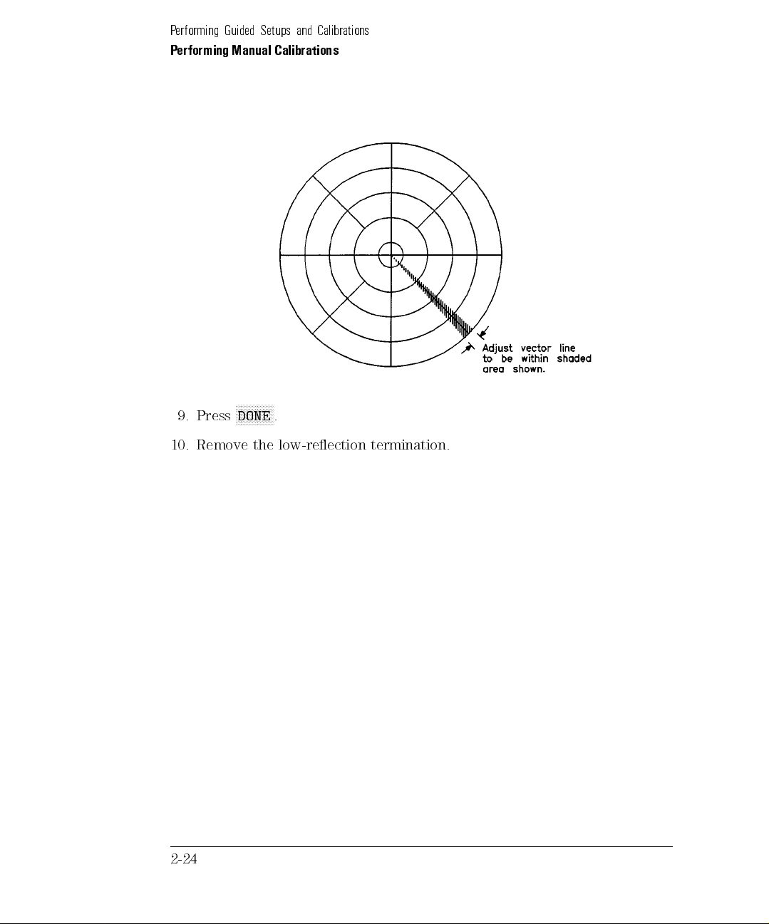
Performing Guided Setups and Calibrations
Performing Manual Calibrations
N
N
N
N
N
N
N
N
N
N
N
N
N
N
Press
9.
DONE
.
10.
Remove
low-reection
the
termination.
2-24
Page 73
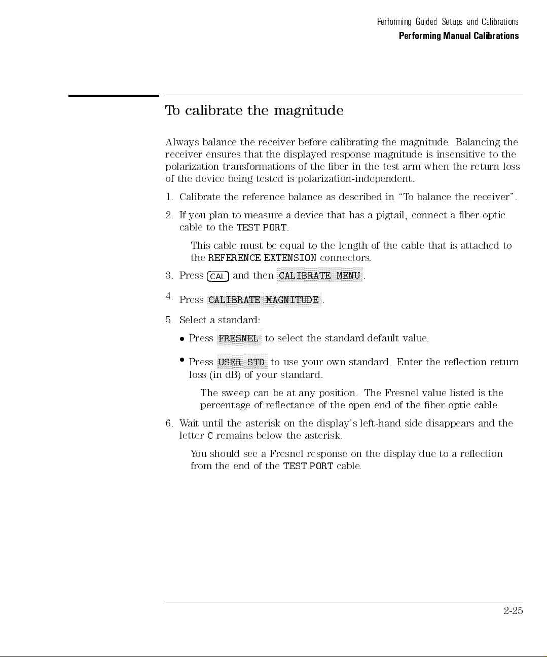
Performing Guided Setups and Calibrations
Performing Manual Calibrations
To calibrate the magnitude
Always balance the receiver before calibrating the magnitude. Balancing the
receiver ensures that the displayed response magnitude is insensitive to the
polarization transformations of the ber in the test arm when the return loss
of the device being tested is polarization-independent.
1. Calibrate the reference balance as described in \To balance the receiver".
2. If you plan to measure a device that has a pigtail, connect a ber-optic
cable to the
TEST PORT
.
is the
cable
to
return
.
3.
4.
5.
This cable
the
REFERENCE
4
Press
CAL
N
N
N
Press
CALIBRATE
a
Select
Press
Press
(in
loss
The
percentage of
must be
and
5
N
N
N
NN
NN
N
N
N
N
N
N
N
N
N
standard:
N
N
NN
N
N
N
N
N
N
N
N
N
FRESNEL
N
N
N
N
N
N
N
N
N
N
N
NN
USER
dB)
sweep
EXTENSION
then
N
N
N
N
N
N
N
N
N
N
N
N
N
N
N
N
N
N
N
N
N
N
N
N
N
N
N
N
N
N
N
N
N
STD
your
of
can
equal to
N
N
N
N
N
N
N
N
N
NN
NN
N
N
N
N
CALIBRATE
N
N
N
N
N
N
N
N
N
N
N
N
NN
NN
N
N
N
N
N
N
N
MAGNITUDE
the
select
to
N
your own
use
to
standard.
any
at
be
reectance
length
the
connectors
N
NN
NN
N
N
N
N
N
N
N
N
N
N
N
N
MENU
N
N
N
N
N
N
.
standard
position.
the
of
cable
the
of
.
N
N
N
N
N
N
N
N
N
N
.
default
value
standard. Enter
Fresnel
The
of
end
open
the
value
ber-optic
the
that
.
attached
is
reection
listed
6. Wait until the asterisk on the display's left-hand side disappears and the
letterCremains below the asterisk.
You should see a Fresnel response on the display due to a reection
from the end of the
TEST PORT
cable.
2-25
Page 74
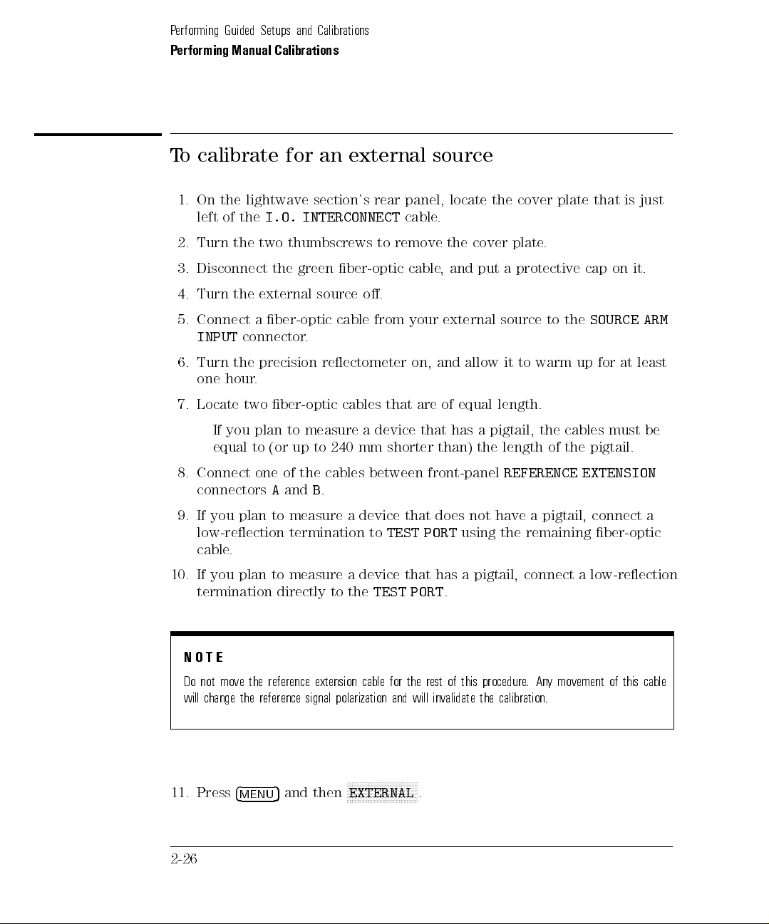
Performing Guided Setups and Calibrations
Performing Manual Calibrations
To calibrate for an external source
1. On the lightwave section's rear panel, locate the cover plate that is just
left of the
I.O. INTERCONNECT
cable.
2. Turn the two thumbscrews to remove the cover plate.
3. Disconnect the green ber-optic cable, and put a protective cap on it.
4. Turn the external source o.
5. Connect a ber-optic cable from your external source to the
INPUT
6. Turn
one
Locate
7.
Connect
8.
connector
the precision
.
hour
two
plan
you
If
to
equal
one
connectors
plan
you
If
9.
low-reection
.
cable
plan to
If you
10.
termination directly to the
.
ber-optic
measure
to
to
up
(or
the
of
.
B
and
A
measure
to
termination
measure a
reectometer on,
are
a
mm
between
device
a
to
device
that
device
shorter
TEST
that
that
that
cables
240
cables
TEST PORT
allow
and
equal length.
of
a
has
the
than)
front-panel
not
does
using
PORT
pigtail,
a
has
.
warm
to
it
pigtail, the
length of
REFERENCE
pigtail,
a
have
remaining
the
connect
NOTE
movement
Any
Do
will
not move
change
the
the
reference
reference
extension
signal
cable
polarization
for
and
the
will
of
rest
invalidate
procedure
this
the calibration.
.
SOURCE ARM
for
up
cables
the
must
pigtail.
EXTENSION
connect
ber-optic
low-reection
a
of
at
this
least
be
a
cable
11. Press
2-26
4
MENU
5
and then
NNNNNNNNNNNNNNNNNNNNN
NNNNN
EXTERNAL
.
Page 75
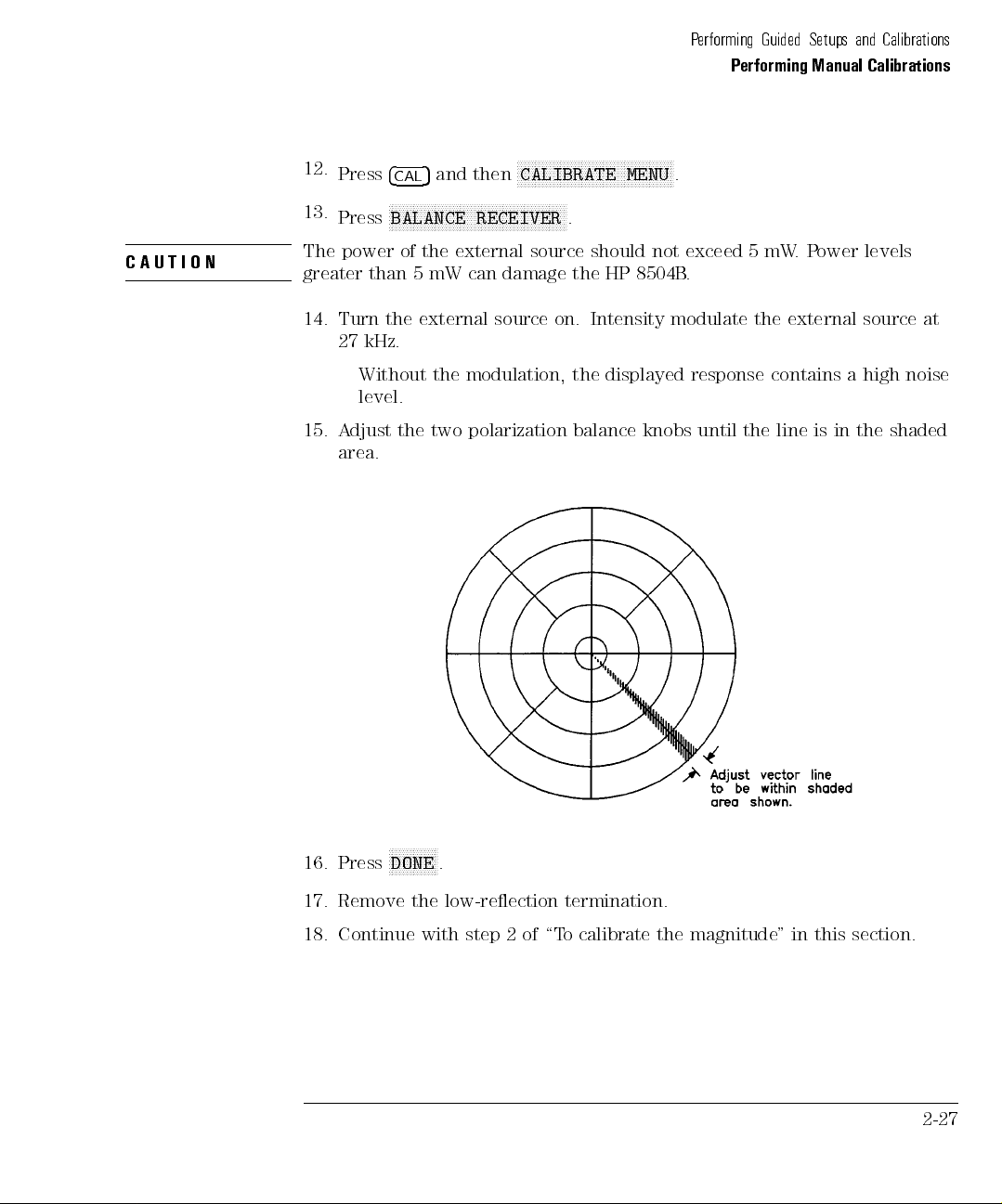
Performing Guided Setups and Calibrations
Performing Manual Calibrations
CAUTION
12.
13.
Press
4
5
and then
CAL
NNNNNNNNNNNNNNNNNNNNNNNNNNNNNNNNNNNNNNNNNNNNNNNNNN
Press
BALANCE RECEIVER
NNNNNNNNNNNNNNNNNNNNNNNNNNNNNNNNNNNNNNNNNNNN
CALIBRATE MENU
.
.
The power of the external source should not exceed 5 mW.Power levels
greater than 5 mW can damage the HP 8504B.
14. Turn the external source on. Intensity modulate the external source at
27 kHz.
Without the modulation, the displayed response contains a high noise
level.
15.
djust
A
the
polarization
two
balance
knobs
shaded
the
in
is
line
the
until
area.
16. Press
Remove
17.
Continue
18.
NNNNNNNNNNNNNN
DONE
the
with
.
low-reection
of
2
step
termination.
o calibrate
\T
magnitude
the
section.
this
in
"
2-27
Page 76
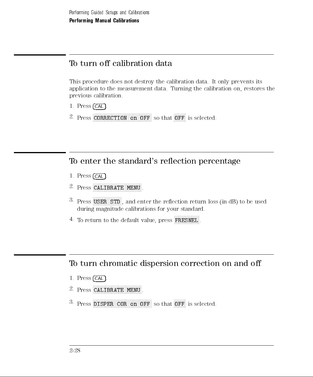
Performing Guided Setups and Calibrations
Performing Manual Calibrations
To turn o calibration data
This procedure does not destroy the calibration data. It only prevents its
application to the measurement data. Turning the calibration on, restores the
previous calibration.
1. Press
2.
o
T
1.
2.
3.
4.
4
5
.
CAL
NNNNNNNNNNNNNNNNNNNNNNNNNNNNNNNNNNNNNNNNNNNNNNNNNNNN
N
Press
CORRECTION on OFF
standard's
enter
Press
Press
Press
the
4
.
5
CAL
N
N
N
N
N
N
N
N
N
N
N
N
N
N
N
N
N
NN
N
N
N
CALIBRATE
N
N
N
N
N
N
N
N
N
N
NN
N
N
N
N
N
N
N
N
N
N
USER
STD
N
N
N
N
during magnitude
return to
To
the
N
N
N
N
N
N
N
N
N
N
N
NN
N
N
N
N
MENU
N
N
,
and
enter
calibrations
default
N
N
N
.
value
NNNNNNNNNN
so that
N
OFF
reection
reection
the
your
for
N
N
N
press
,
FRESNEL
is selected.
return
standard.
N
N
N
N
N
N
N
N
N
N
N
N
N
N
N
N
percentage
dB)
(in
loss
NN
N
N
.
to
be
used
To turn chromatic dispersion correction on and o
1.
2.
3.
2-28
Press
4
.
5
CAL
N
N
N
N
N
N
N
NN
N
N
N
N
N
N
N
N
N
Press
CALIBRATE
NNNNNNNNNNNNNNNNNNNNNNNNN
NNNNNNN
Press
DISPER COR on OFF
N
N
N
N
N
N
N
N
N
N
NN
N
N
N
N
N
N
N
N
NN
N
N
N
N
MENU
.
NNNNNNNNNNNNNNNNNNNNN
so that
NNNNNNN
OFF
NNNN
is selected.
Page 77
Performing Guided Setups and Calibrations
Performing Manual Calibrations
To use the Option 001 cable tray
The maximum length of cable that can be coiled inside the tray is
approximately 200 cm (79 inches).
CAUTION
1. Connect one end of the ber-optic cable to the front panel
EXTENSION B
connector.
REFERENCE
2. Coil the cable in the tracy as shown in the following gure. Do not allow
any more cable outside the cable tray than is necessary.
If the cable must be lengthened inside the tray by using two cables and
an adapter
cable tray
Connect
3.
REFERENCE
optic
Fiber
diameters
stretching
Attach
4.
.
the
EXTENSION
cable
than
less
cable
the
the top
the connectors
, put
remaining
be
can
mm
50
.
the
onto
the
of
end
connector
A
irrepairably
inches).
(2
body
main
adapter
and
ber-optic
.
damaged
damage
This
the
of
cable to
by
cable
foam
the
in
bending
mainly caused
is
.
tray
cutout
the front-panel
into circles
it
inside
with
by
the
2-29
Page 78
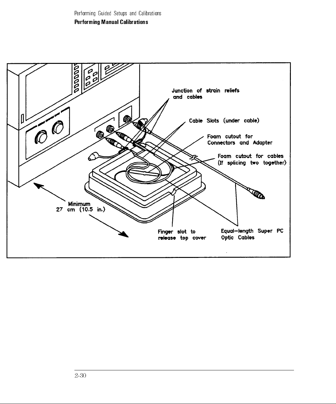
Performing Guided Setups and Calibrations
Performing Manual Calibrations
2-30
Page 79
3
erforming
P
Measurements
Page 80
Contents
Performing Measurements
Once you've calibrated the precision reectometer, you're ready to make
measurements. In this chapter, you'll learn about changing the measurement
range, temporarily storing traces, and changing the colors on the display.
You'll also learn how to use displayed markers and how to test the shape
of displayed responses using limit lines. Limit lines are valuable tools for
pass/fail testing on production lines.
The last section of this chapter shows you how to create hard copies of the
screen,
the
plotter
printer
a
display
the precision
points and
on
reectometer can
instrument parameters
Setting
Reducing
Using
Creating
Storing Traces to Memory
the Measurement
select the
o
T
automatically
o
T
change
o
T
change
o
T
Displayed
reduce
o
T
Markers
display
o
T
To change the measurement range
To make relative measurements
To position a xed reference marker
To change the peak denition
To turn markers o
Limit
enter
o
T
To display or hide limit lines
To turn on limit testing
Tutorial: Using Limit Lines
To view memory traces
or
source
displayed
the
refractive
the
displayed
the
:
:
:
:
peak
a
Lines
limit-line
Range
wavelength
to
tune
Noise
:
:
:
:
:
:
:
:
response
::::: ::::::: :::::: ::::::: ::::::: ::::::::: ::::::::
:
:
:
:
:
:
segments
addition
In
.
print or
.
:
:
:
:
response
a
:
:
:
scale
:
:
index
::
::
:
:
:
:
:
:
:
::
:
:
noise
::
::
::
::
:
:
:
:
:
:
:
:
::::::: ::::::: :::::: ::::::: ::::::: :::
::::: ::::::: ::::::: :::::: ::::::: :::::::
:
:
:
:
:
:
::
:
:
:
:
:
:::::: :::
::::::: :::::
::::::
::::::: :
::::::: :
:::::::::::::::::::::::::
::::: ::::::: ::::::: ::::::
:
:
:
:
:
:
:
:
:
:
:
:
:
:
:
:
:
:
:
::
::
:
:
:
:
:
hardcopies
of
:
:
:
:
:
:
:
:
:
:
:
:
:
:
:
:
:
:
:
:
:
:
:
:
:
:
:
:
:
:
:
:
:
:
:
:
:
:
:
:
:
:
:
:
:
:
:
:
:
:
:
:
:
::
:
all
::
:
:
:
:
:
:
:
:
:
:
:
:
:
:
:
:
:
:
:
:
:
:
:
:
:
:
::
::
:
:
:
:
:
:
:
::
:
:
:
:
getting
to
listing
plot a
:
:
:
:
:
:
:
:
:
:
:
:
:
:
:
:
:
::
:
:
:
:
:
:
:
:
:
::
:
:
:
:
::
::
:
:
:
:
:
:
:
:
:
:
:
:
::
::
::
:
:
:
:
:
:
:
:
::
:
:
:
:
:
:
:::::: ::::::: :::::: ::::::: ::::::: :
::::::::::::::::::::::::::::::::
:
:
:
::
:
:
:
:
:
:
:
:
:
:
::
:
:::::: :::::: ::::::: ::::::
:::::: :::::: ::::::: ::::::
:::::::::::::::::::::::::
of
measurement
:
:
:
:
:
:
:
:
:
:
:
:
:
:
:
:
:
:
:
:
::
:
:
:
:
:
:
:
:
:
:
:
:
:
:
:
::
:
:
:
:
:
:
:
::
::
:
:
:
:
:
:
:
:
:
:
:
:
:
::
::
:
:
::
::
::
::
:
:
:
:
:
:
:
:
:
:
::
::
:
:
:
:
:
:
:
:
:
:
:
:
::
:
:
:
:
:
:
:
:
:
:
:
:
::
:
:
:
:
:
::::::
::::::::
::::::::::
::::::::::::
::::::: :::::
:
::
:
:
::
:
:
3-4
:
:
:
:
:
3-6
:
:
:
:
3-7
:
:
:
:
3-7
:
:
:
:
:
3-8
:
:
:
:
:
3-9
:
:
:
:
:
3-11
:
:
:
:
3-12
:
:
:
3-16
::
3-16
3-16
3-17
3-17
3-18
3-19
:
:
:
3-23
:
:
:
3-23
3-24
3-25
3-34
3-35
3-2
Page 81
Performing Measurements
Performing Manual Calibrations
Contents (continued)
Saving Instrument States to Registers
To save to a register
To recall a register
To increase user memory
Saving Instrument States to Files
To save to a disk
To change a le name
To recall an external le
To delete an external le
To format an external disk
To connect a disk drive
Changing
adjust
o
T
turn on
To
turn o
o
T
Printing
print the
o
T
plot
o
T
print
o
T
enter
o
T
abort
o
T
Colors
and
the
and
displayed
the warning
the \done"
Plotting
display
display
plot
or
printer/plotter
the
print
a
:::::: ::::::: ::::::: :::::: ::::::: ::::::::: ::::::
::::: ::::::: ::::::: :::::: ::::::: ::::::::: :::::::::
:::::::::::::::::::::::::::::::::::::::::::
:::::: ::::::: ::::::: :::::: ::::::: :::::
:::::: ::::::: :::::: ::::::: ::::::: ::::::::: ::::::::::
::::: ::::::: :::::: ::::::: ::::::: ::::::::: ::::::
:::::: :::::: ::::::: ::::::: :::::: ::::::::: :::
:::::: ::::::: :::::: ::::::: ::::::: ::::::::: :
::::::: ::::::: :::::: ::::::: ::::::: ::::::::
:::::::::::::::::::::::::::::::::::::::::::::
arnings
::
:
:
beep
:
:
:
:
:
beep
:
:
:
:
:
:
:
:
:
:
:
:
:
:
:
:
W
:
:
:
:
:
type
:
:
:
:
:
:
:
:
:
:
:
::
:
:
:
:
:
:
:
:
:
:
:
:
:
:
and
:
:
:
:
:
:
udible
A
colors
:
:
measurement
plot
or
::::: ::::::: :::::: ::::::: ::::::: ::
:
:
:
:
:
:
:
:
:
:
:
:
:
:
:
:
:
:
:
:
:
:
:
:
:
:
:
:
:
:
:
:
:
:
:
:
:
:
:
:
:
:
:
::
::
::
::
:
:
:
:
:
:
:
:
:
:
:
:
::
::
::
::
:
:
:
:
:
:
:
:
:
:
:
:
:
:
:
:
:
:
:
:
:
:
:
:
:
:
::
::
:
:
:
:
:
:
:
:
:
:
:
:
:
:
:
:
:
:
:
:
:
:
:
:
:
:
:
:
:
:
:
::
::
:
:
:
:
:
:
:
:
:
:
:
:
:
:
:
:
:
:
:
:
:
:
:
:
:
:
:
::
::
:
:
:
:
:
:
:
:
:
:
:
:
:
:
:
:
:
:
:
:
:
:
:
:
:
:
:
::
:
:
:
:
:
:
:
:
:
:
:
:
:
:
:
::
:
:
parameter
address
and
:
:
:
:
:
:
:
:
values
:
:
:
:
:
:
:
:
:
:
:
:
:
:
:
:
:
:
:
::
:
:
:
:
:
:
:
:
:
:
::
:
:
:
:
:
:
:
3-36
3-38
3-38
3-39
3-40
3-41
3-42
3-43
3-43
3-43
3-44
3-45
:
:
:
:
:
:
3-45
::
::
::
3-45
:
:
:
:
:
:
3-46
:
:
:
:
:
:
:
3-47
:
:
:
:
:
3-48
::
:
:
:
:
:
3-48
:
:
:
:
:
3-49
:
:
:
:
:
:
3-49
:
:
:
:
:
:
3-50
:
:
:
:
:
:
3-3
Page 82
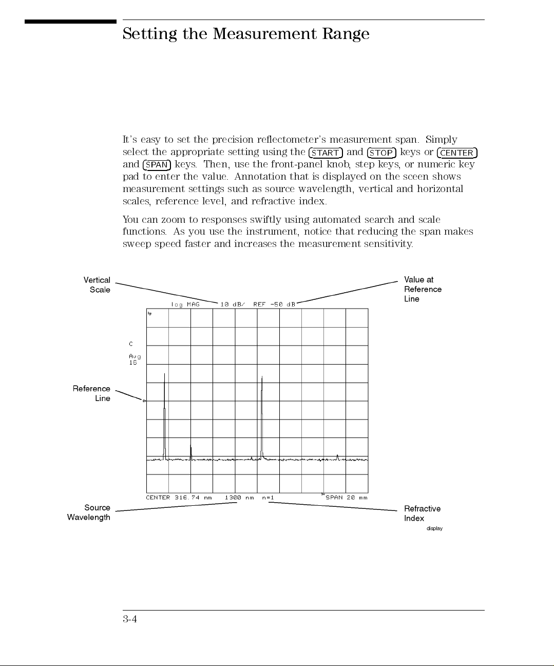
Setting the Measurement Range
It's easy to set the precision reectometer's measurement span. Simply
select the appropriate setting using the
and
4
5
keys. Then, use the front-panel knob, step keys, or numeric key
SPAN
4
START
5
and
4
STOP
5
keys or
4
CENTER
pad to enter the value. Annotation that is displayed on the sceen shows
measurement settings such as source wavelength, vertical and horizontal
scales, reference level, and refractive index.
You can zoom to responses swiftly using automated search and scale
makes
span
functions
.
sweep speed
you
As
faster and
the
use
increases the
instrument,
reducing
notice
that
measurement sensitivity
the
.
5
3-4
Page 83
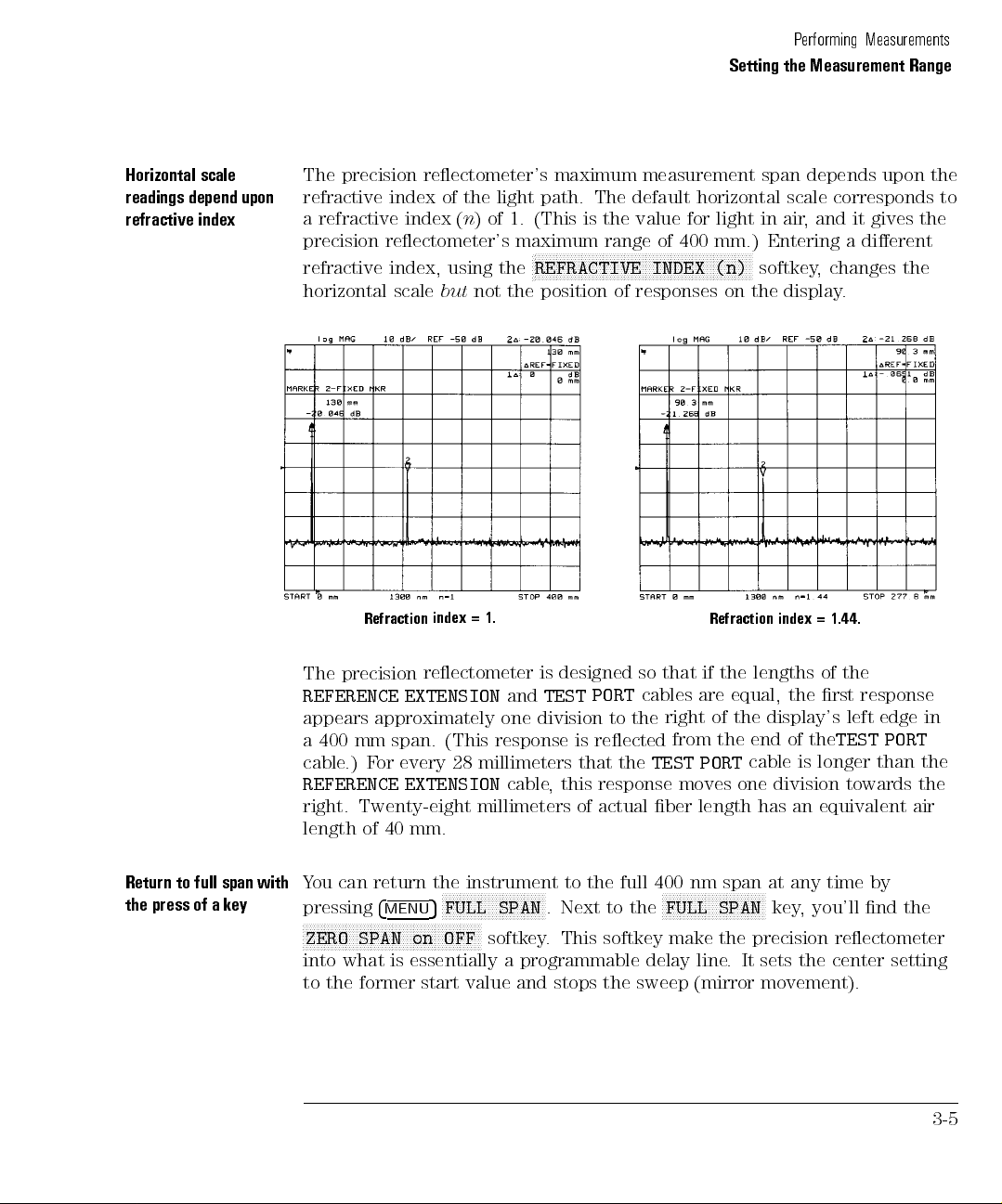
Performing Measurements
Setting the Measurement Range
Horizontal scale
readings depend upon
refractive index
The precision reectometer's maximum measurement span depends upon the
refractive index of the light path. The default horizontal scale corresponds to
a refractive index (n) of 1. (This is the value for light in air, and it gives the
precision reectometer's maximum range of 400 mm.) Entering a dierent
refractive index, using the
horizontal scale
Refraction
precision
The
REFERENCE
appears
400
a
cable
approximately
mm
or
F
.)
but
index
reectometer
EXTENSION
(This
span.
28
every
not the position of responses on the display.
=
millimeters
REFERENCE EXTENSION
NNNNNNNNNNNNNNNNNNNNNNNNNNNNNNNNNNNNNNNNNNNNNNNNNNNNNNNNNNNNN
N
REFRACTIVE INDEX (n)
1.
designed
is
PORT
TEST
and
the
division
one
response
to
reected
is
that
the
that
so
cables
right
TEST
if
are
from
PORT
softkey, changes the
Refraction
the
of
the end
index
lengths
equal,
display's left
the
the
of the
cable is
1.44.
=
the
of
response
rst
edge in
TEST PORT
longer than
cable, this response moves one division towards the
the
right. Twenty-eight millimeters of actual ber length has an equivalent air
length of 40 mm.
Return
press
the
with
span
full
to
key
a
of
ou
Y
pressing
N
NN
N
return
can
4
MENU
N
N
NN
N
N
N
N
N
N
N
N
N
N
NN
N
N
N
N
N
N
N
N
N
N
ZERO SPAN on OFF
the
N
N
N
N
5
FULL
N
N
NN
N
N
N
N
N
N
N
N
N
instrument to
NN
N
N
N
N
N
N
N
N
N
N
N
N
N
N
N
N
N
N
N
N
SPAN
N
N
N
N
NN
N
softkey. This
into what is essentially a programmable delay line
the
N
N
N
the
to
Next
.
N
N
N
N
N
N
N
N
FULL
N
N
N
NN
N
N
N
N
N
N
SPAN
N
N
N
N
N
N
N
NN
N
you'll
,
key
nd
the
softkey make the precision reectometer
. It sets the center setting
by
time
any
at
span
nm
400
full
to the former start value and stops the sweep (mirror movement).
3-5
Page 84
Performing Measurements
Setting the Measurement Range
The sweep can be
stopped
External sources can be
used
Normally, the precision reectometer sweeps the measurement range
continually. Single sweeps are available by pressing
4
MEAS
NNNNNNNNNNNNNNNNNNN
N
5
SINGLE
.Each
time this softkey is pressed, one sweep is taken and then the sweep stops.
You also can force any sweep to restart at the beginning regardless of the
current sweep position. This is especially valuable in wide measurement
spans where sweeps take a few seconds to complete.To restart a sweep,
press
4
NNNNNNNNNNNNNNNNNNNNNNNNNNNNNNNNNNNNNNNNNNNNNNN
5
MEAS
MEASURE RESTART
.
In addition to the internal 1300 nm and 1550 nm sources, you can connect an
external source for the measurements. The external source input is provided
meant
not
is
It
normal
data.
how
.
.
calibration
Refer
calibrate
to
to
\T
and
o
the
convenience
a
as
typical
the
for
correction
calibrate
precision
select
To
Press
1.
2.
Press
The
users
for
When
.
user
features
for an
are
external source
reectometer for
source
the
4
N
.
5
MENU
NN
NN
NN
N
N
N
N
N
N
N
N
N
N
N
N
N
nm
1300
N
NNNNNNNNNNNNNNNNNNNNNNNNN
EXTERNAL
N
NN
N
N
or
1550
selection turns o the internal sources. The external
with
using
applied
not
"
use with
wavelength
NN
NN
NN
NN
N
N
N
N
N
N
N
N
N
N
N
N
nm
very
an
in
N
to
advanced
external
the
to
Chapter
external
an
select
applications
,
source
measurement
learn
to
2
source
wavelength.
the
source input is provided as a convenience for users with very advanced
applications. Note that normal calibration and correction features are
not available with an external source . Use the entry keys to enter the
wavelength
of
the
external
source.
3-6
Page 85
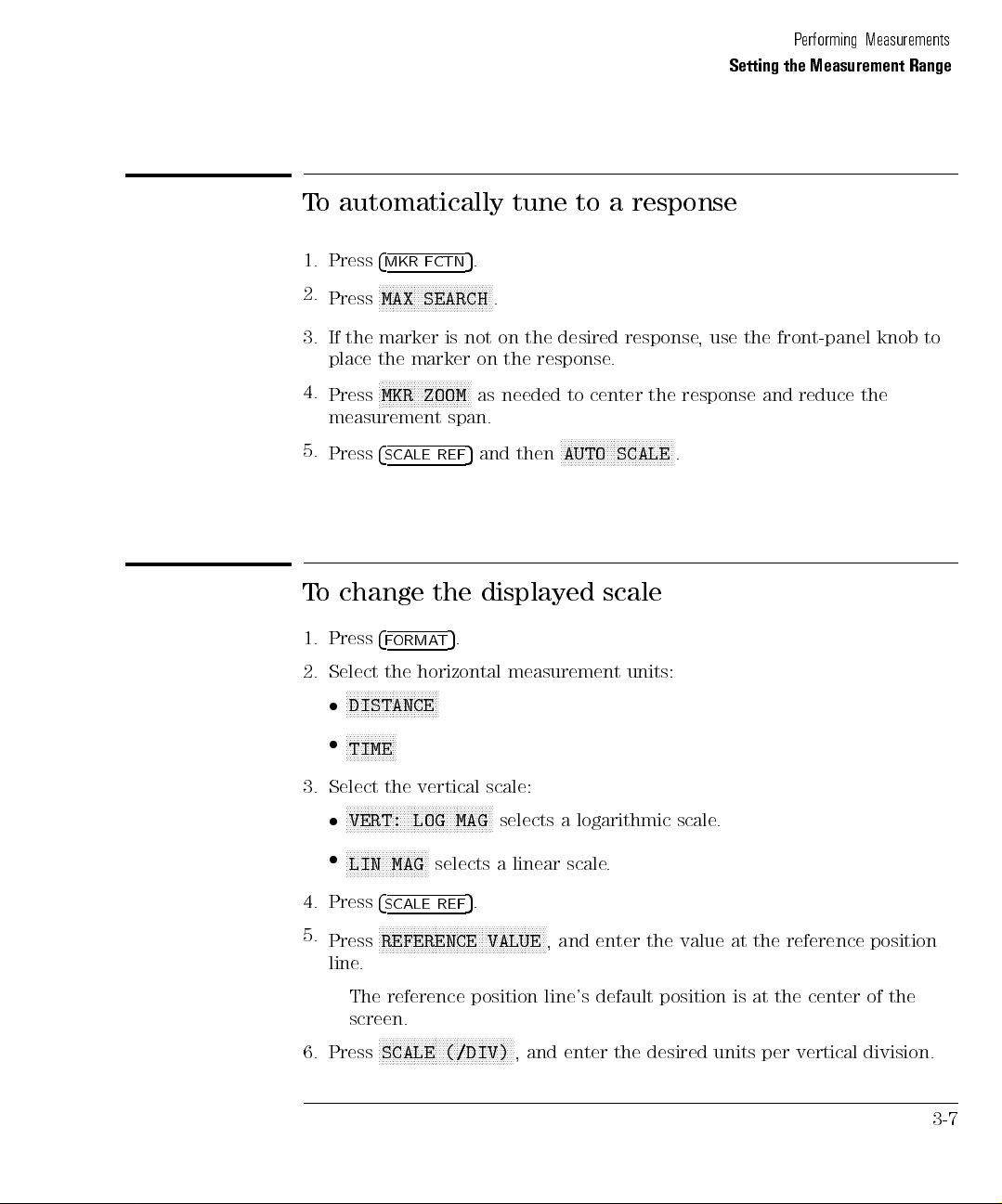
To automatically tune to a response
Performing Measurements
Setting the Measurement Range
1. Press
2.
Press
4
MKR FCTN
5
.
NNNNNNNNNNNNNNNNNNNNNNNNNNNNNNNN
MAX SEARCH
.
3. If the marker is not on the desired response, use the front-panel knob to
place the marker on the response.
NNNNNNNNNNNNNNNNNNNNNNNNN
Press
N
MKR ZOOM
as needed to center the response and reduce the
4.
measurement span.
5.
T
1.
2.
o
4
Press
SCALE
change the
4
Press
F
the
Select
N
NN
NN
N
N
N
N
N
N
DISTANCE
N
N
N
N
N
N
N
N
NN
N
TIME
ORMA
horizontal
N
N
N
N
N
N
N
N
N
N
N
N
N
N
N
N
N
REF
5
T
N
5
.
and then
displayed
N
AUTO
scale
measurement
SCALE
units:
.
N
N
NN
NN
NN
NN
N
N
N
N
N
N
N
N
N
N
N
N
N
N
N
N
N
NN
NN
3. Select the vertical scale:
NNNNNNNNNNNNNNNNNNNNNNNNNNNNNNNNNNNNNNNNN
VERT: LOG MAG
NNNNNNNNNNNNNNNNNNNNNNN
LIN MAG
selects a linear scale.
selects a logarithmic scale.
4.
5.
SCALE REF
N
N
N
N
N
N
NN
N
N
N
Press
REFERENCE VALUE
.
5
N
N
N
N
NN
N
N
N
N
N
N
N
N
N
N
N
NN
N
N
N
N
N
N
N
N
N
N
NN
N
N
N
N
N
, and enter the value at the reference position
4
Press
line.
The reference position line's default position is at the center of the
screen.
6. Press
NNNNNNNNNNNNNNNNNNN
SCALE (/DIV)
NNNNNNNNNNNNNNNNNNN
, and enter the desired units per vertical division.
3-7
Page 86
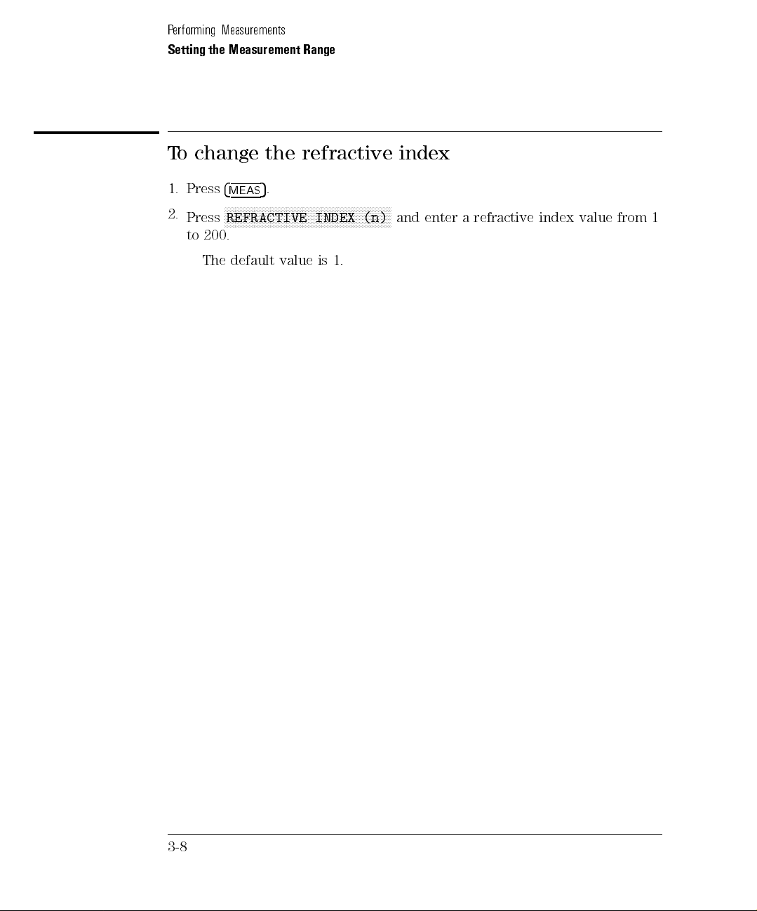
Performing Measurements
Setting the Measurement Range
To change the refractive index
1. Press
2.
4
5
MEAS
NNNNNNNNNNNNNNNNNNNNNNNNNNNNNNNNNNNNNNNNNNNNNNNNNNNNNNNNNNNNNN
Press
REFRACTIVE INDEX (n)
to 200.
The default value is 1.
.
and enter a refractive index value from 1
3-8
Page 87
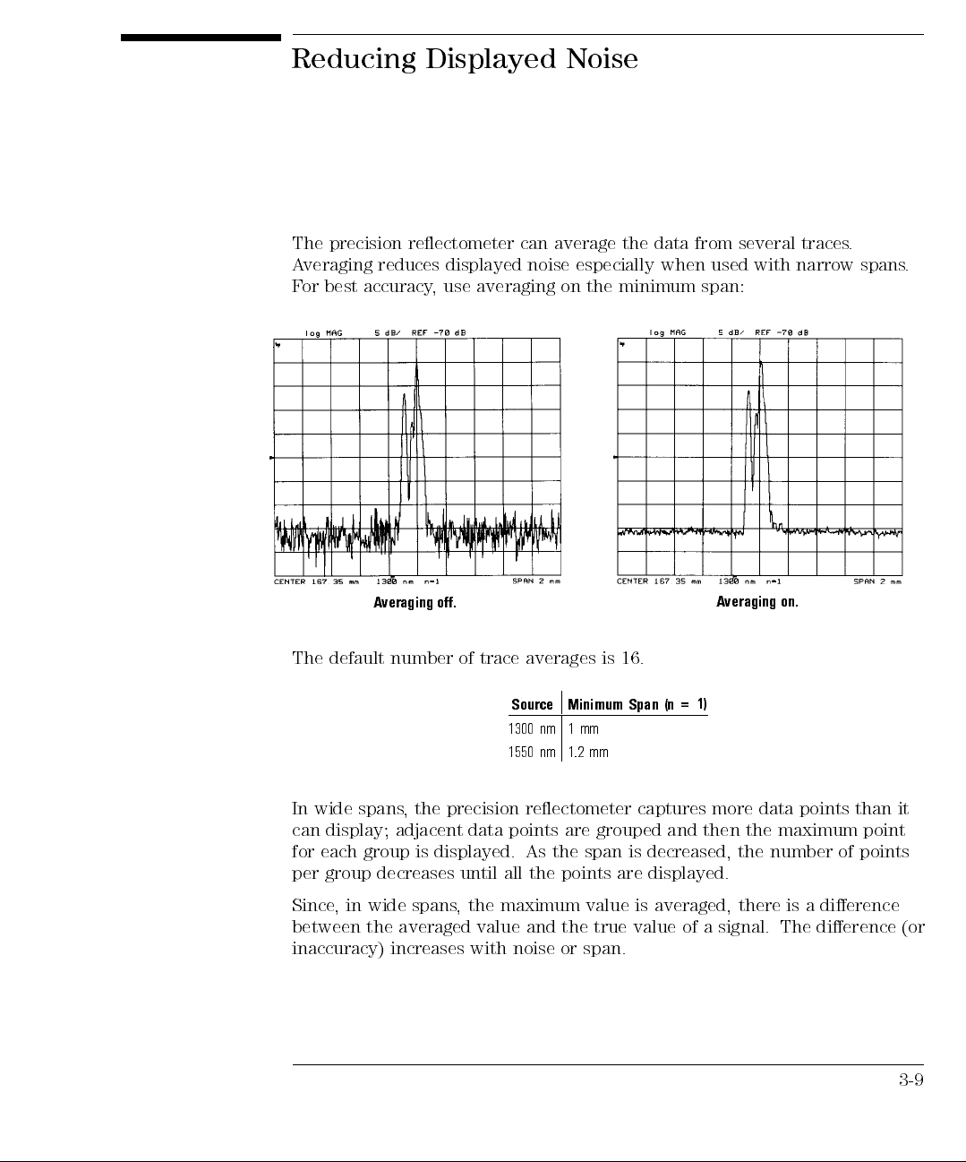
Reducing Displayed Noise
The precision reectometer can average the data from several traces.
Averaging reduces displayed noise especially when used with narrow spans.
For best accuracy, use averaging on the minimum span:
on.
The
default
veraging
A
number
o.
of
trace
averages
is
Source Minimum
1300nm1
mm
16.
Span
veraging
A
1)
=
(n
1550 nm 1.2 mm
In wide spans, the precision reectometer captures more data points than it
can display; adjacent data points are grouped and then the maximum point
points
displayed.
is
group
each
for
decreases
group
per
Since, in wide spans
until
,the
As
displayed.
all
the
points
are
maximum value is averaged, there is a dierence
decreased,
is
span
the
between the averaged value and the true value of
the number
a signal. The dierence (or
of
inaccuracy) increases with noise or span.
3-9
Page 88

Performing Measurements
Reducing Displayed Noise
The following equation shows the algorithm:
Sn
An=
Kn+01
where:
An= current average
Sn= current measurement
Kn=nforn<F or F for nF
F = averaging factor
1
1
(
0
K
n
A
n01
)
3-10
Page 89
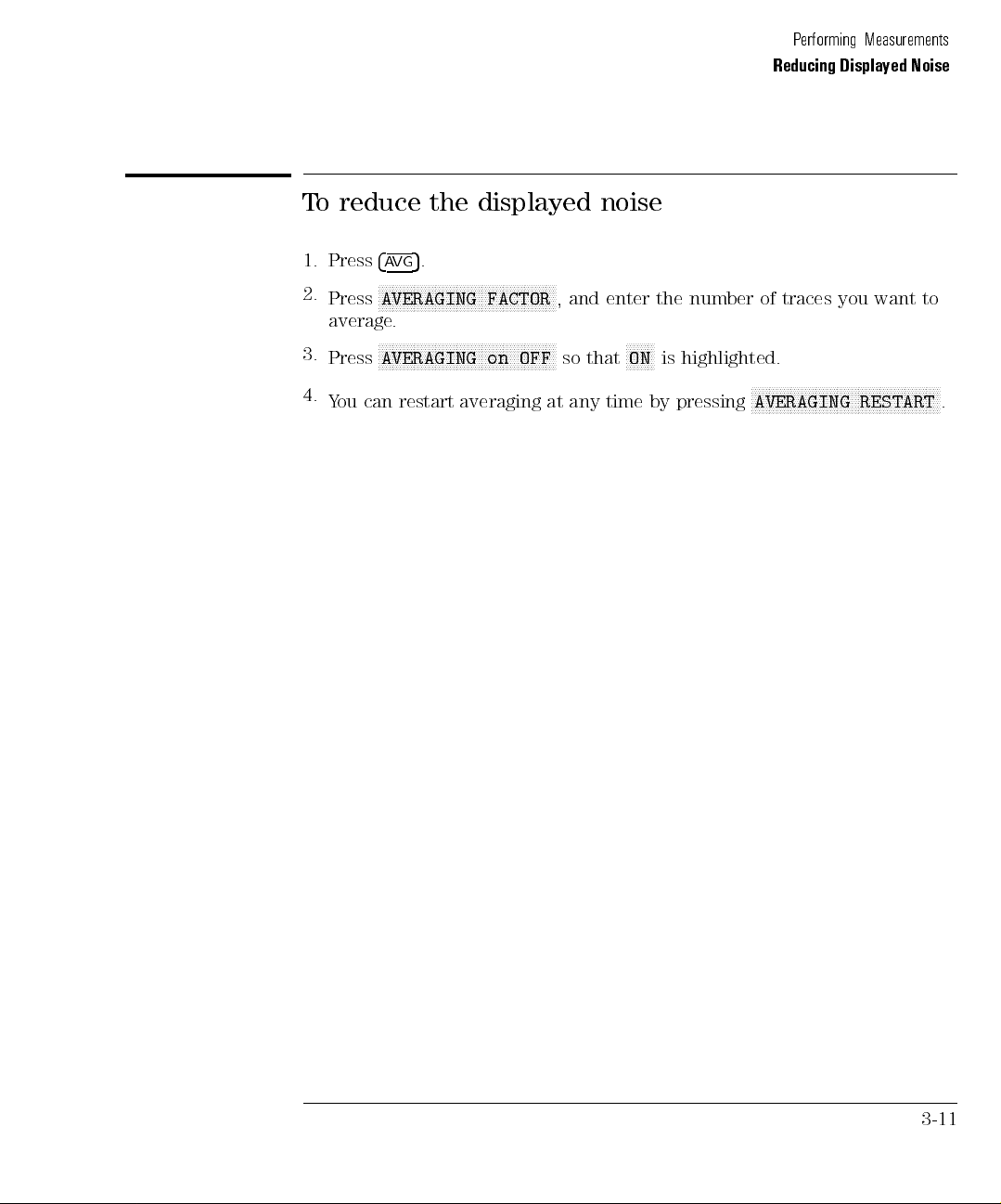
To reduce the displayed noise
Performing Measurements
Reducing Displayed Noise
1. Press
2.
3.
4.
4
5
.
AVG
NNNNNNNNNNNNNNNNNNNNNNNNNNNNNNNNNNNNNNNNNNNNNNNNNN
Press
AVERAGING FACTOR
average.
NNNNNNNNNNNNNNNNNNNNNNNNNNNNNNNNNNNNNNNNNNNNNNNNNN
Press
AVERAGING on OFF
You can restart averaging at any time by pressing
, and enter the number of traces you want to
so that
NNNNNNNN
ON
is highlighted.
NNNNNNNNNNNNNNNNNNNNNNNNNNNNNNNNNNNNNNNNNNNNNNNNNNNNN
AVERAGING RESTART
.
3-11
Page 90
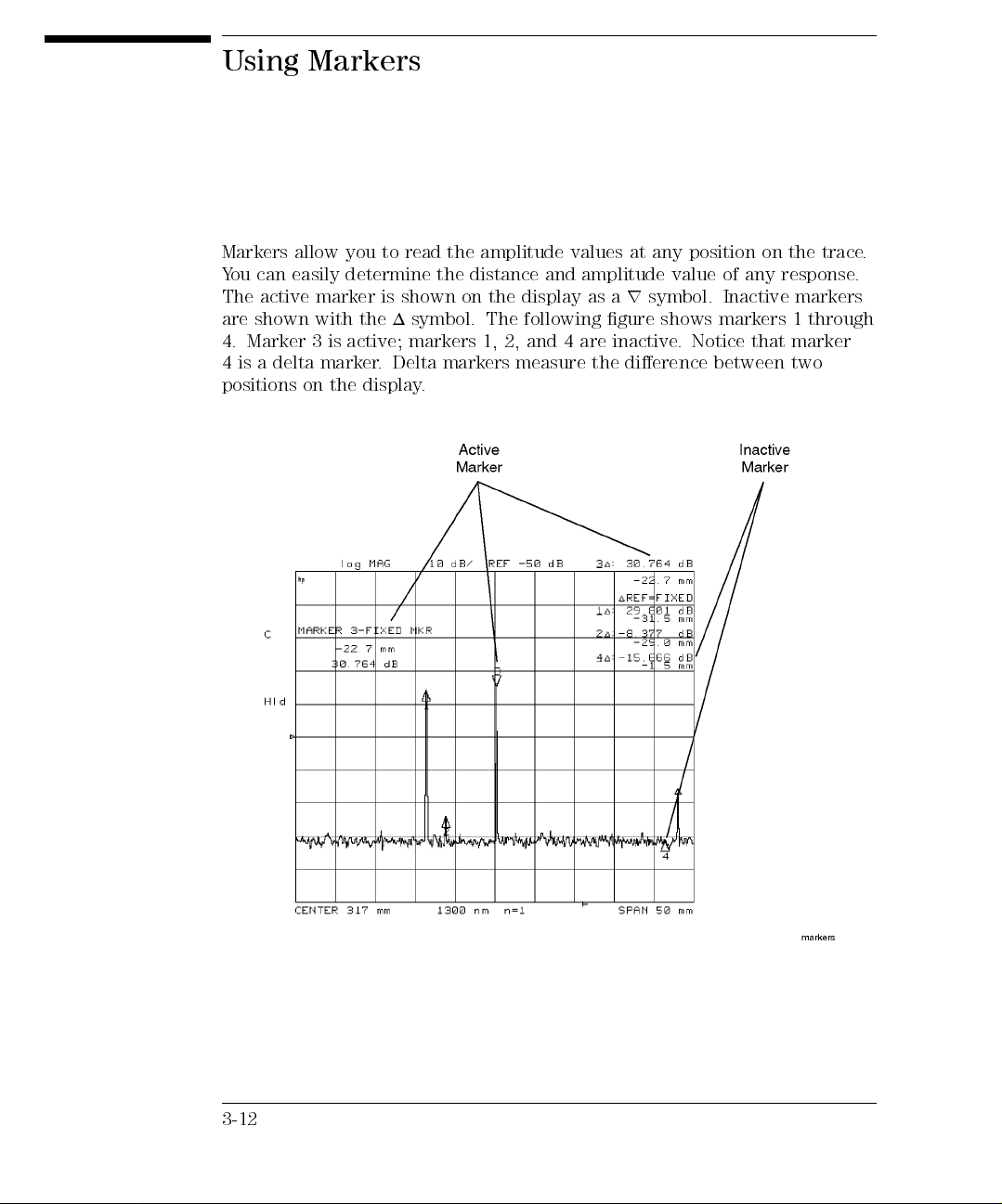
Using Markers
Markers allow you to read the amplitude values at any position on the trace.
You can easily determine the distance and amplitude value of any response.
The active marker is shown on the display as arsymbol. Inactive markers
are shown with the 1 symbol. The following gure shows markers 1 through
4. Marker 3 is active; markers 1, 2, and 4 are inactive. Notice that marker
4 is a delta marker. Delta markers measure the dierence between two
positions on the display.
3-12
Page 91
markers
1
relative
display
values
Performing Measurements
Using Markers
Markers are accessed from two front-panel keys:
Use
4
5
to display up to four markers, an additional xed marker,and
MRK
delta markers.
Use
4
MKR FCTN
measurement span based on marker positions.
The active marker can be moved to any point on the trace. When a
logarithmic amplitude scale is used, response values are displayed in dB;
when a linear amplitude scale is used, values are shown as the ratio of
reected power to the incident power. The displayed marker values are valid
even when the measured data is above or below the range displayed on the
screen.
displaying
When
designated
be
relative
delta
than
delta
distance
reference
inactive
the
character
5
to search for peak responses and to change the
markers
four
the
of
any
delta
the
as
(or
displayed
is
marker
appears
markers
reference
time)
next to
,
marker
amplitude
and
a
as
triangles
the
small
.)
marker
The
.
1
one
If
displayed
this
from
character
the
of
number
markers
reference
(This
.
markers
the
on
xed
a
or
show
marker
character
the
is
trace
point
the
The
.
smaller
is
reference
.
can
,
the
a
is
marker
xed
The
marker
delta
special
reference
What if a memory trace
is displayed?
dene a
can
ou
Y
peak
.
trace
the
set
NN
NN
xed
a
on
N
N
FIXED
N
N
on
screen;
the
N
NN
NN
N
N
N
N
N
N
N
N
N
N
N
N
N
N
N
N
peak to
MKR
current
the
to
N
N
N
N
N
. Other
marker
be
a
andb, shown
a
it
N
N
N
N
N
N
N
N
N
N
N
N
N
N
N
N
N
N
VALUE
active
markers can
.
identied.
must
trace
not
is
N
N
NN
NN
N
N
a
3-13
standard
four
the
of
Each
marker
xed
the
However
limited
position
marker
then
If both data and memory are displayed, the marker values apply to the data
trace. If memory only is displayed, the marker values apply to the memory
trace.
ou
Y
The
increase and then decrease
oors, in order to be dened as a peak.
If peak excursion is dened as 20 dB
in the following gure
,
to
the
position,
activated
be
change
can
default
the
trace
xed
value
.
marker
by
and
the
is
markers
can
N
N
N
N
N
N
N
Use
FIXED
. The
pressing
values
their
amplitude
The
.
dB
6
, relative to the surrounding responses or noise
, must be at least 20 dB in order to be considered
can
position
be
N
N
N
N
N
N
NN
NN
N
N
N
N
N
N
N
N
N
MKR
xed marker
N
N
N
N
N
N
N
N
NN
NN
NN
NN
MARKER
referenced
variation
value
N
POSITION
NN
NN
NN
NN
N
N
N
N
N
N
N
N
N
FIXED
!
required
species
, then the values of
N
N
can
N
N
N
N
N
to
the
N
N
N
and
be
NN
NN
N
N
N
N
N
N
N
MARKER
the
for
amount that
anywhere
N
N
N
N
N
N
N
N
N
N
N
NN
NN
N
N
N
N
N
N
N
N
N
N
N
N
N
N
positioned
be
only
to
Page 92
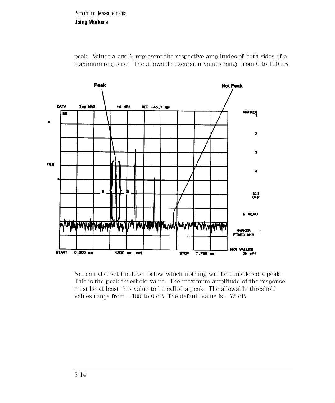
Performing Measurements
Using Markers
peak. Valuesaandbrepresent the respective amplitudes of both sides of a
maximum response. The allowable excursion values range from 0 to 100 dB.
You can also set the level below which nothing will be considered a peak.
This is the peak threshold value. The maximum amplitude of the response
must be at least this value to be called a peak. The allowable threshold
.
dB
75
is
values
3-14
range
from
0
100
to
default
The
.
dB
0
value
0
Page 93
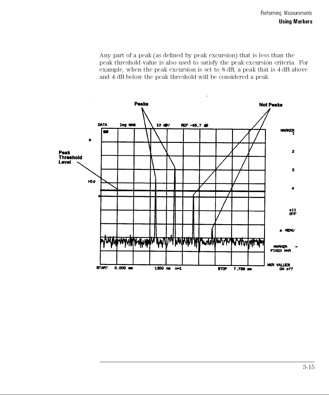
Performing Measurements
Using Markers
Any part of a peak (as dened by peak excursion) that is less than the
peak threshold value is also used to satisfy the peak excursion criteria. For
example, when the peak excursion is set to 8 dB, a peak that is 4 dB above
and 4 dB below the peak threshold will be considered a peak.
3-15
Page 94
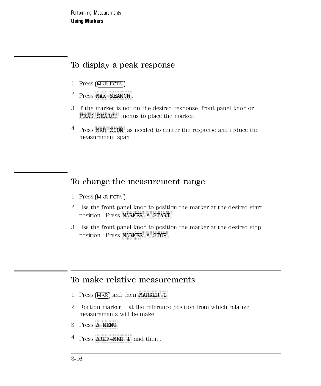
Performing Measurements
Using Markers
To display a peak response
1. Press
2.
3. If the marker is not on the desired response, front-panel knob or
4.
o
T
1.
2.
3.
4
MKR FCTN
NNNNNNNNNNNNNNNNNNNNNNNNNNNNNNNN
Press
MAX SEARCH
NNNNNNNNNNNNNNNNNNNNNNNNNNNNNNNNNNN
PEAK SEARCH
NNNNNNNNNNNNNNNNNNNNNNNNNN
Press
MKR ZOOM
measurement
change
Press
the
Use
position.
the
Use
position.
the
4
CTN
F
MKR
front-panel
Press
front-panel
Press
5
.
.
menus to place the marker.
as needed to center the response and reduce the
span.
measurement
.
5
position
to
knob
N
N
N
N
N
N
N
N
N
N
N
N
N
MARKER
knob
NN
NN
N
N
N
N
N
N
N
N
N
N
MARKER
N
N
NN
NN
N
N
N
NN
NN
N
N
N
N
N
1
to
N
N
N
N
N
1
N
N
N
N
N
N
N
N
N
N
START
position
N
N
N
N
N
N
N
N
N
N
STOP
N
NN
N
N
N
NN
range
marker
the
N
NN
NN
at
desired
the
.
marker
the
NN
at
desired
the
.
start
stop
make
o
T
Press
1.
osition marker
2. P
relative
4
5
MKR
then
and
1 at the reference position from which relative
measurements will be make
NNNNNNNNNNNNNNNNNNNN
3. Press
4.
Press
1 MENU
NNNNNNNNN
1REF=MKR 1
.
NNNNNNNNNNNNNNNNNNNNNNN
3-16
measurements
N
MARKER
.
1
N
N
N
N
N
N
N
NN
N
N
N
N
N
N
N
N
N
N
N
NN
N
N
N
.
and then .
Page 95

Performing Measurements
Using Markers
5.
To position a xed reference marker
1.
2.
3.
4.
NNNNNNNNNNNNNNNNNNNNNNNNNN
Press
MARKER 2
Press
4
5
MKR
NNNNNNNNNNNNNNNNNNNNNNNNNNNNNNNNNNNNNNNNNNNNNNN
Press
1REF= FIXED MKR
NN
NN
N
N
N
N
N
N
N
N
N
N
N
N
Press
FIXED
osition the
P
N
N
N
N
N
N
N
N
N
N
N
FIXED
ou
Y
N
N
N
N
N
N
MARKER
softkeys.
NN
N
N
NN
N
N
N
N
can
NN
N
N
N
N
N
N
N
N
MKR
N
N
N
N
N
N
N
N
N
N
N
N
also
N
N
N
!
to read delta values (marker 20marker 1).
and then
N
N
N
NN
NN
MKR
marker using
N
N
N
N
N
N
N
N
VALUE
N
N
N
N
N
N
N
N
FIXED
NNNNNNNNNNNNNNNNNNNN
1MENU
N
NN
NN
NN
N
N
N
N
N
N
N
N
N
N
N
N
N
N
MENU
N
N
N
N
N
N
NN
NN
.
specify the
N
N
N
N
N
N
N
N
N
N
N
N
N
N
N
N
N
N
N
NN
N
MKR
.
.
N
N
N
N
N
N
FIXED
position
N
N
N
N
N
or
.
NN
NN
N
N
N
N
N
N
N
N
N
N
N
N
N
N
N
N
MKR POSITION
value
4
F
MKR
N
N
N
N
N
CTN
N
N
N
N
5
N
N
N
using
N
NN
NN
N
N
N
N
N
N
N
N
N
the
NN
N
N
N
N
N
N
N
N
N
N
N
N
MARKER
N
N
N
N
and
4
5
MKR
N
N
N
N
N
N
N
N
N
N
N
N
!
N
N
N
N
N
N
N
FIXED
N
N
N
NN
N
N
N
N
N
N
N
N
N
N
N
N
N
N
N
N
N
N
N
N
MKR
o change
T
1.
Press
4
MKR FCTN
N
2.
3.
4.
NNNNNNNNNNNNNNNNNNNNNNNNNNNNNNNNNN
Press
DEFINE PEAK
value
the
Enter
NN
N
N
N
N
N
N
N
N
N
N
Press
PEAK
considered a peak.
peak
the
5
and then
that
N
N
N
N
N
N
N
N
NN
N
N
N
N
N
N
N
N
N
N
THRESHOLD
and then
denes
N
N
N
N
N
N
N
NN
N
N
N
denition
NNNNNNNNNNNNNNNNNNNNNNNNNNNNNNNNNNN
PEAK SEARCH
N
NNNNNNNNNNNNNNNNNNNNNNNNNNNNNNNNNNNNNNNNNNN
PEAK EXCURSION
peak.
a
the
enter
and
.
value
.
below
which
nothing
will
be
3-17
Page 96

Performing Measurements
Using Markers
To turn markers o
1. Press
2.
Press
4
5
.
MKR
NNNNNNNNNNNNNNNNNNNNNNN
all OFF
.
3-18
Page 97
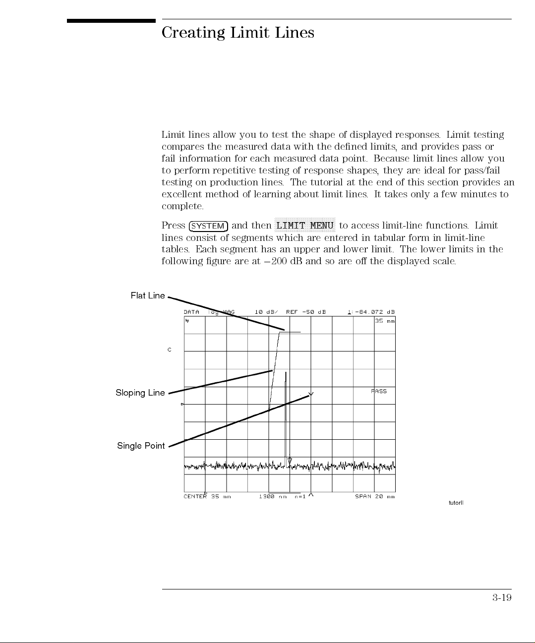
Creating Limit Lines
Limit lines allow you to test the shape of displayed responses. Limit testing
compares the measured data with the dened limits, and provides pass or
fail information for each measured data point. Because limit lines allow you
to perform repetitive testing of response shapes, they are ideal for pass/fail
testing on production lines. The tutorial at the end of this section provides an
excellent method of learning about limit lines. It takes only a few minutes to
complete.
NNNNNNNNNNNNNNNNNNNNNNNNNNNNNNNN
Limit
4
Press
SYSTEM
consist
lines
.
tables
following
Each
gure
then
and
5
segments which
of
are
at
has
0
200
segment
LIMIT
upper
an
dB
to
MENU
are entered
lower
and
are
so
and
access
in tabular
limit.
the
o
limit-line
form in
The
displayed
functions
lower limits
scale.
.
limit-line
in the
3-19
Page 98
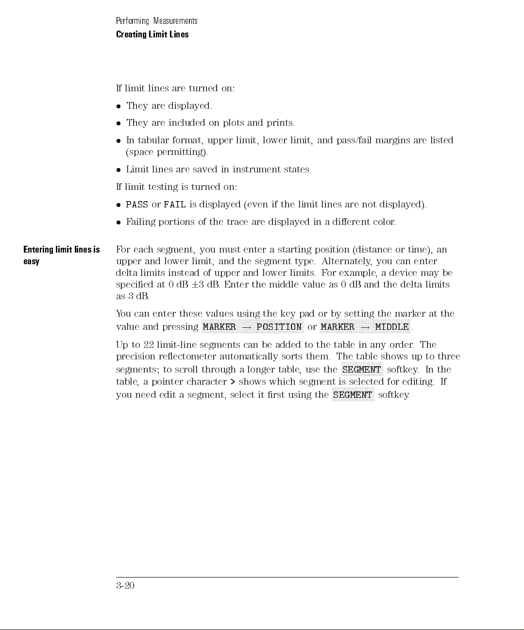
Entering
easy
limit
lines
Performing Measurements
Creating Limit Lines
If limit lines are turned on:
They are displayed.
They are included on plots and prints.
In tabular format, upper limit, lower limit, and pass/fail margins are listed
(space permitting).
Limit lines are saved in instrument states.
If limit testing is turned on:
PASSorFAIL
portions
ailing
F
is
or
F
upper
delta
specied
as
each
3
and
limits
.
dB
segment,
lower
instead
dB
0
at
is displayed (even if the limit lines are not displayed).
.
the
of
you must
limit,
upper
of
dB
3
6
trace
and
Enter
.
are
enter a
segment
the
and
the
displayed
starting
lower
middle
type
limits
value
dierent
a
in
position
Alternately
.
example
or
F
.
0
as
color
(distance
you
,
,a
dB and
time),
or
can enter
device may
delta
the
an
limits
Y
value
Up to
pressing
and
22 limit-line
N
N
N
N
MARKER
segments
values
these
enter
can
ou
precision reectometer
segments;
table
you
to
pointer character
,a
a segment,
edit
need
through
scroll
3-20
the
using
N
N
N
N
N
N
N
N
N
N
NN
N
N
N
N
N
N
N
N
!
can
NN
N
N
N
N
N
N
N
N
N
N
N
N
N
POSITION
be
N
automatically sorts
longer
a
>
shows
select it
which segment
rst using
key
N
N
N
N
N
N
N
N
N
N
added
table
pad
N
N
N
,
N
N
or
the
to
them.
use
the
by
or
N
N
N
N
N
N
N
N
N
N
N
N
MARKER
table
The
the
is
NN
NN
N
SEGMENT
setting
N
N
N
N
N
N
N
N
N
N
N
N
N
N
NN
!
any
in
table
NN
N
N
N
N
N
N
N
N
N
N
N
N
N
N
N
SEGMENT
selected
N
N
N
N
N
N
N
N
N
N
N
N
N
N
NN
the
NN
N
N
N
N
N
N
N
N
N
MIDDLE
order
shows
N
N
N
N
NN
softkey
for
N
N
softkey
marker at
N
N
N
N
N
N
N
N
N
N
.
The
.
up
.
editing.
.
to
In
the
three
the
If
Page 99
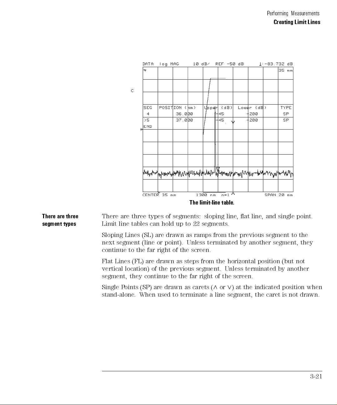
Performing Measurements
Creating Limit Lines
There
segment
are
three
types
are
There
line
Limit
Sloping
segment
next
continue
three
tables
Lines
to
(SL)
(line
the
types
hold
can
are
or point).
far right
segments:
of
up
drawn
of the
limit-line
The
segments
22
to
ramps
as
Unless terminated
screen.
sloping
from
table.
line
.
the
line
at
,
previous
by another
single
and
,
segment
segment, they
point.
to
the
Flat Lines (FL) are drawn as steps from the horizontal position (but not
vertical location) of the previous segment. Unless terminated by another
segment, they continue to the far right of the screen.
Single Points (SP) are drawn as carets (^or_) at the indicated position when
drawn.
not
stand-alone
When
.
used
terminate
to
a
line
segment,
the caret
is
3-21
Page 100
Performing Measurements
Creating Limit Lines
Indications of pass/fail
conditions
be
can
lines
Limit
shifted
Several indications of pass or fail status are provided when limit testing is on:
A
PASSorFAIL
The trace vector leading to any measured point that is out of limits is
message is displayed at the right of the display.
displayed in a dierent color. It appears normal on a print or plot.
The limit fail beeper sounds if it is turned on.
An asterisk * is shown next to any listed point that is out of limits.
A bit is set in the HP-IB status byte.
E
T
O
N
a
of
number
changing
move
to
of
can
checked
be
Limits are
device
measurement
can
lines
Limit
to
limits
the
specications
lines away
limit
the
detail.
trace
at
only
specication
of
out
points.
oset
be
correspond
dier in
that
from the
actual
the
without displa
horizontally
with a
stimulus or
measured
data
ying
or
change in
data trace
the
If
points.
sure
Be
.
FAIL
This
test
.
setup
It can
vertically
the
amplitude.
temporarily for
point
to
density
specify
useful
is
or
,
also
visual
insucient,
is
suitable
a
for
device
for
used
be
examination
NOTE
The three
N
N
N
N
N
NN
N
N
N
POSITION
limit
the
3-22
NN
N
N
N
N
N
oset
N
N
N
N
N
N
N
N
N
N
segments
NNNNNNNNNNNNNNNNNNNNNNNNNNNNNNNNNNNNNNNNNNNNNNNNN
N
(
ys
ke
AMPLITUDE OFFSET
N
N
N
N
N
NN
N
N
N
N
N
N
N
N
N
N
NN
N
OFFSET
look out
)
shift
of
the
place
check
,
limit
N
,
MARKER
segments but
the
if
see
to
NNNNNNNNNNNNNNNNNNNNNNNNNNNNNNNNNNNNNNNNNNNNNNNNNNNNNN
AMP.OFF.
!
values
limit
the
change
not
do
position
y
have
been shifted
in
,
and
in
or
table
the
amplitude
If
.
.
 Loading...