

Page 1

BenchCel Microplate Handler
User Guide
Original Instructions
Page 2

Notices
WARNING
CAUTION
Manual Part Number
G5580-90000 Revision B
November 2020
Copyright
© Agilent Technologies, Inc. 2020
No part of this manual may be reproduced
in any form or by any means (including
electronic storage and retrieval or
translation into a foreign language) without
prior agreement and written consent from
Agilent Technologies, Inc. as governed by
United States and international copyright
laws.
Contact Information
Agilent Technologies Inc.
Automation Solutions
5301 Stevens Creek Blvd.
Santa Clara, CA 95051
USA
Web:
https://www.agilent.com
Contact page:
https://www.agilent.com/en/contactus/page
Documentation feedback:
documentation.automation@agilent.com
Acknowledgments
Microsoft® and Windows® are either
registered trademarks or trademarks of the
Microsoft Corporation in the United States
and other countries.
Warranty
The material contained in this document is
provided “as is,” and is subject to being
changed, without notice, in future editions.
Further, to the maximum extent permitted
by applicable law, Agilent disclaims all warranties, either express or implied, with
regard to this manual and any information
contained herein, including but not limited
to the implied warranties of merchantability
and fitness for a particular purpose. Agilent
shall not be liable for errors or for incidental
or consequential damages in connection
with the furnishing, use, or performance of
this document or of any information contained herein. Should Agilent and the user
have a separate written agreement with
warranty terms covering the material in this
document that conflict with these terms,
the warranty terms in the separate agreement shall control.
Technology Licenses
The hardware and/or software described in
this document are furnished under a license
and may be used or copied only in
accordance with the terms of such license.
Restricted Rights Legend
If software is for use in the performance of
a U.S. Government prime contract or
subcontract, Software is delivered and
licensed as “Commercial computer
software” as defined in DFAR 252.227-7014
(June 1995), or as a “commercial item” as
defined in FAR 2.101(a) or as “Restricted
computer software” as defined in FAR
52.227-19 (June 1987) or any equivalent
agency regulation or contract clause. Use,
duplication or disclosure of Software is
subject to Agilent Technologies’ standard
commercial license terms, and non-DOD
Departments and Agencies of the U.S.
Government will receive no greater than
Restricted Rights as defined in FAR 52.22719(c)(1-2) (June 1987). U.S. Government
users will receive no greater than Limited
Rights as defined in FAR 52.227-14
(June1987) or DFAR 252.227-7015 (b)(2)
(November 1995), as applicable in any
technical data.
Safety Notices
A WARNING notice denotes a hazard. It calls attention to an operating
procedure, practice, or the like that, if
not correctly performed or adhered
to, could result in personal injury or
death. Do not proceed beyond a
WARNING notice until the indicated
conditions are fully understood and
met.
CAUTION notice denotes a hazard.
A
It calls attention to an operating procedure, practice, or the like that, if not
correctly performed or adhered to,
could result in damage to the product
or loss of important data. Do not proceed beyond a
the indicated conditions are fully
understood and met.
CAUTION notice until
Page 3

Contents
Preface . . . . . . . . . . . . . . . . . . . . . . . . . . . . . . . . . . . . . . . . . . . . . . . . . . . . . . . . . . . . . . . . . . . . . . . . . . . . . . . . . . . . . . v
About this guide. . . . . . . . . . . . . . . . . . . . . . . . . . . . . . . . . . . . . . . . . . . . . . . . . . . . . . . . . . . . . . . . . . . . . . . vi
Accessing product user information . . . . . . . . . . . . . . . . . . . . . . . . . . . . . . . . . . . . . . . . . . . . . . . . . . . . viii
1. Safety guidelines. . . . . . . . . . . . . . . . . . . . . . . . . . . . . . . . . . . . . . . . . . . . . . . . . . . . . . . . . . . . . . . . . . . . . . . . . 1
General safety information . . . . . . . . . . . . . . . . . . . . . . . . . . . . . . . . . . . . . . . . . . . . . . . . . . . . . . . . . . . . . 2
Safety and regulatory compliance . . . . . . . . . . . . . . . . . . . . . . . . . . . . . . . . . . . . . . . . . . . . . . . . . . . . . . . 3
Emergency stops . . . . . . . . . . . . . . . . . . . . . . . . . . . . . . . . . . . . . . . . . . . . . . . . . . . . . . . . . . . . . . . . . . . . . 5
Safety equipment and features . . . . . . . . . . . . . . . . . . . . . . . . . . . . . . . . . . . . . . . . . . . . . . . . . . . . . . . . . 8
Potential safety hazards . . . . . . . . . . . . . . . . . . . . . . . . . . . . . . . . . . . . . . . . . . . . . . . . . . . . . . . . . . . . . . 10
2. Introduction . . . . . . . . . . . . . . . . . . . . . . . . . . . . . . . . . . . . . . . . . . . . . . . . . . . . . . . . . . . . . . . . . . . . . . . . . . . . . 13
BenchCel Microplate Handler description . . . . . . . . . . . . . . . . . . . . . . . . . . . . . . . . . . . . . . . . . . . . . . . 14
Hardware overview . . . . . . . . . . . . . . . . . . . . . . . . . . . . . . . . . . . . . . . . . . . . . . . . . . . . . . . . . . . . . . . . . . . 15
Integration options for workstations . . . . . . . . . . . . . . . . . . . . . . . . . . . . . . . . . . . . . . . . . . . . . . . . . . . . 25
Labware considerations. . . . . . . . . . . . . . . . . . . . . . . . . . . . . . . . . . . . . . . . . . . . . . . . . . . . . . . . . . . . . . . 27
Software description . . . . . . . . . . . . . . . . . . . . . . . . . . . . . . . . . . . . . . . . . . . . . . . . . . . . . . . . . . . . . . . . . 29
3. Installing BenchCel Microplate Handler . . . . . . . . . . . . . . . . . . . . . . . . . . . . . . . . . . . . . . . . . . . . . . . . . 35
Installation workflow . . . . . . . . . . . . . . . . . . . . . . . . . . . . . . . . . . . . . . . . . . . . . . . . . . . . . . . . . . . . . . . . . 36
Verifying laboratory requirements . . . . . . . . . . . . . . . . . . . . . . . . . . . . . . . . . . . . . . . . . . . . . . . . . . . . . . 37
Unpacking BenchCel Microplate Handler . . . . . . . . . . . . . . . . . . . . . . . . . . . . . . . . . . . . . . . . . . . . . . . . 42
Mounting the robot . . . . . . . . . . . . . . . . . . . . . . . . . . . . . . . . . . . . . . . . . . . . . . . . . . . . . . . . . . . . . . . . . . . 44
About integrating devices in a BenchCel Workstation . . . . . . . . . . . . . . . . . . . . . . . . . . . . . . . . . . . . . 47
Connecting the power source. . . . . . . . . . . . . . . . . . . . . . . . . . . . . . . . . . . . . . . . . . . . . . . . . . . . . . . . . . 50
Connecting the pendant directly to the BenchCel device . . . . . . . . . . . . . . . . . . . . . . . . . . . . . . . . . . 51
Connecting the pendant through the Robot Disable Hub . . . . . . . . . . . . . . . . . . . . . . . . . . . . . . . . . . 53
Connecting and disconnecting the air source . . . . . . . . . . . . . . . . . . . . . . . . . . . . . . . . . . . . . . . . . . . . 55
Connecting the computer . . . . . . . . . . . . . . . . . . . . . . . . . . . . . . . . . . . . . . . . . . . . . . . . . . . . . . . . . . . . . 57
Installing the shield . . . . . . . . . . . . . . . . . . . . . . . . . . . . . . . . . . . . . . . . . . . . . . . . . . . . . . . . . . . . . . . . . . . 61
4. Setting up the BenchCel device. . . . . . . . . . . . . . . . . . . . . . . . . . . . . . . . . . . . . . . . . . . . . . . . . . . . . . . . . . 63
Setup workflow . . . . . . . . . . . . . . . . . . . . . . . . . . . . . . . . . . . . . . . . . . . . . . . . . . . . . . . . . . . . . . . . . . . . . . 64
Starting up and shutting down . . . . . . . . . . . . . . . . . . . . . . . . . . . . . . . . . . . . . . . . . . . . . . . . . . . . . . . . . 66
Creating BenchCel device in the VWorks software. . . . . . . . . . . . . . . . . . . . . . . . . . . . . . . . . . . . . . . . 68
Opening BenchCel Diagnostics . . . . . . . . . . . . . . . . . . . . . . . . . . . . . . . . . . . . . . . . . . . . . . . . . . . . . . . . 73
Creating profiles . . . . . . . . . . . . . . . . . . . . . . . . . . . . . . . . . . . . . . . . . . . . . . . . . . . . . . . . . . . . . . . . . . . . . 76
Initializing the device . . . . . . . . . . . . . . . . . . . . . . . . . . . . . . . . . . . . . . . . . . . . . . . . . . . . . . . . . . . . . . . . . 82
Setting and managing teachpoints . . . . . . . . . . . . . . . . . . . . . . . . . . . . . . . . . . . . . . . . . . . . . . . . . . . . . 84
iiiBenchCel Microplate Handler User Guide
Page 4

Contents
5. Setting sensor thresholds. . . . . . . . . . . . . . . . . . . . . . . . . . . . . . . . . . . . . . . . . . . . . . . . . . . . . . . . . . . . . . . . 99
Overview for setting sensor thresholds . . . . . . . . . . . . . . . . . . . . . . . . . . . . . . . . . . . . . . . . . . . . . . . . 100
Calculating the Plate presence threshold. . . . . . . . . . . . . . . . . . . . . . . . . . . . . . . . . . . . . . . . . . . . . . . 102
Determining the optimum Orientation sensor offset . . . . . . . . . . . . . . . . . . . . . . . . . . . . . . . . . . . . . 107
Calculating the Orientation threshold . . . . . . . . . . . . . . . . . . . . . . . . . . . . . . . . . . . . . . . . . . . . . . . . . . 111
Worksheet for setting sensor thresholds. . . . . . . . . . . . . . . . . . . . . . . . . . . . . . . . . . . . . . . . . . . . . . . 113
6. Preparing for a run. . . . . . . . . . . . . . . . . . . . . . . . . . . . . . . . . . . . . . . . . . . . . . . . . . . . . . . . . . . . . . . . . . . . . . 115
Workflow for operating the BenchCel Microplate Handler . . . . . . . . . . . . . . . . . . . . . . . . . . . . . . . . 116
Handling the labware racks . . . . . . . . . . . . . . . . . . . . . . . . . . . . . . . . . . . . . . . . . . . . . . . . . . . . . . . . . . 117
Filling and emptying the labware racks . . . . . . . . . . . . . . . . . . . . . . . . . . . . . . . . . . . . . . . . . . . . . . . . 119
Installing and uninstalling the labware racks. . . . . . . . . . . . . . . . . . . . . . . . . . . . . . . . . . . . . . . . . . . . 123
Performing pre-run checks . . . . . . . . . . . . . . . . . . . . . . . . . . . . . . . . . . . . . . . . . . . . . . . . . . . . . . . . . . . 128
7. Maintenance and troubleshooting. . . . . . . . . . . . . . . . . . . . . . . . . . . . . . . . . . . . . . . . . . . . . . . . . . . . . . . 129
Routine maintenance. . . . . . . . . . . . . . . . . . . . . . . . . . . . . . . . . . . . . . . . . . . . . . . . . . . . . . . . . . . . . . . . 130
Cleaning up after a protocol run . . . . . . . . . . . . . . . . . . . . . . . . . . . . . . . . . . . . . . . . . . . . . . . . . . . . . . 132
Replacing the fuse . . . . . . . . . . . . . . . . . . . . . . . . . . . . . . . . . . . . . . . . . . . . . . . . . . . . . . . . . . . . . . . . . . 134
Hardware problems . . . . . . . . . . . . . . . . . . . . . . . . . . . . . . . . . . . . . . . . . . . . . . . . . . . . . . . . . . . . . . . . . 137
Software error messages . . . . . . . . . . . . . . . . . . . . . . . . . . . . . . . . . . . . . . . . . . . . . . . . . . . . . . . . . . . . 139
Diagnostic tools . . . . . . . . . . . . . . . . . . . . . . . . . . . . . . . . . . . . . . . . . . . . . . . . . . . . . . . . . . . . . . . . . . . . 146
Adjusting the stacker gripper pressure. . . . . . . . . . . . . . . . . . . . . . . . . . . . . . . . . . . . . . . . . . . . . . . . . 158
Reporting problems . . . . . . . . . . . . . . . . . . . . . . . . . . . . . . . . . . . . . . . . . . . . . . . . . . . . . . . . . . . . . . . . . 162
A. Quick reference. . . . . . . . . . . . . . . . . . . . . . . . . . . . . . . . . . . . . . . . . . . . . . . . . . . . . . . . . . . . . . . . . . . . . . . . . 165
Rack-release button indicator light . . . . . . . . . . . . . . . . . . . . . . . . . . . . . . . . . . . . . . . . . . . . . . . . . . . . 166
BenchCel Diagnostics - Controls tab. . . . . . . . . . . . . . . . . . . . . . . . . . . . . . . . . . . . . . . . . . . . . . . . . . . 167
BenchCel Diagnostics - Jog/Teach tab . . . . . . . . . . . . . . . . . . . . . . . . . . . . . . . . . . . . . . . . . . . . . . . . 170
BenchCel Diagnostics - Labware tab . . . . . . . . . . . . . . . . . . . . . . . . . . . . . . . . . . . . . . . . . . . . . . . . . . 173
BenchCel Diagnostics - General Settings tab . . . . . . . . . . . . . . . . . . . . . . . . . . . . . . . . . . . . . . . . . . . 178
BenchCel Diagnostics - Profiles tab . . . . . . . . . . . . . . . . . . . . . . . . . . . . . . . . . . . . . . . . . . . . . . . . . . . 179
Teachpoint Details dialog box . . . . . . . . . . . . . . . . . . . . . . . . . . . . . . . . . . . . . . . . . . . . . . . . . . . . . . . . 182
iviv
BenchCel Microplate Handler User Guide
Page 5

Preface
This preface contains the following topics:
• “About this guide” on page vi
• “Accessing product user information” on page viii
v
Page 6

Preface
About this guide
About this guide
Who should read this guide
This user guide is for people with the following job roles:
Job role Responsibilities
Installer Unpacks, installs, and tests the device before it is used.
Integrator Configures hardware and writes software.
Lab manager,
administrator, or
technician
Operator Performs the daily production work on the device and solves
What this guide covers
This guide describes the G5580A BenchCel Microplate Handler and earlier R-Series
models. This guide covers installation, setup, operation, and maintenance.
This guide does not provide instructions for the following:
• Agilent devices that are integrated with the BenchCel Microplate Handler in a
workstation configuration, such as the Bravo Platform, PlateLoc Thermal
Microplate Sealer, Microplate Labeler, and Labware MiniHub
• Third-party devices
For more information about these topics, see the relevant user guides for these
products.
• Manages the automation system that contains the device
• Develops the applications that are run on the system
• Develops training materials and standard operating
procedures for operators
routine problems.
Software version
This guide is applicable for the following software:
• BenchCel Diagnostics 21.3.0, which is included in VWorks software 14.0 and later.
• BenchCel Diagnostics versions included in VWorks software 12.3 – 13.1.x.
What is new in this edition
and
Description See…
Added descriptions for VWorks software
14.0.
vi
“Software description” on page 29
BenchCel Microplate Handler User Guide
Page 7

Description See…
Preface
About this guide
Related guides
Updated the Robot Disable Hub
descriptions to specify the 3-Port Robot
Disable Hub.
Updated the instructions for creating the
device file to include how to select the
teachpoint for an integrated device.
Updated the profile and teachpoint
descriptions and procedures to reflect
changes introduced in VWorks software
14.0.
Updated the fuse replacement procedure
to make the description consistent for
both 115 V and 230 V power.
Added a description of the indicators on
the Controls tab.
• “Safety equipment and features” on
page 8
• “Connecting the pendant through
the Robot Disable Hub” on page 53
“Specifying BenchCel accessibility at
other devices” on page 72
• “Creating profiles” on page 76
• “Setting and managing teachpoints”
on page 84
• “BenchCel Diagnostics - Profiles
tab” on page 179
“Replacing the fuse” on page 134
“BenchCel Diagnostics - Controls tab” on
page 167
You should use this guide in conjunction with the following guides:
• Automation Solutions Products General Safety Guide. Provides general safety
information and describes potential safety hazards that you might encounter when
using Automation Solutions products. A copy of this safety guide is included with
your shipment.
• VWorks software guides:
– VWorks Automation Control Setup Guide. Explains how to define labware and
labware classes, liquid classes, and pipetting techniques.
The VWorks 14.0 version also explains the VWorks compliance features and
how to set up an experiments databases.
– VWorks Automation Control User Guide. Explains how to create protocols, and
set task parameters for each device in the system.
• BenchCel Microplate Handler Quick Guide. The quick guide summarizes the
instructions in this user guide.
• Agilent Technologies device user guides. These guides explain how to set up and
use the devices that you integrate with the BenchCel Microplate Handler, such as
the Bravo Platform User Guide.
• Third-party device user documents, if applicable. These guides explain how to set
up and use the third-party devices.
BenchCel Microplate Handler User Guide
vii
Page 8

Preface
Accessing product user information
Accessing product user information
About this topic
This topic describes the different formats of user information and explains how to
access it for the Agilent Automation Solutions products.
Where to find user information
The user information is available in the following locations:
• Knowledge base. The help system for the Automation Solutions products is
available from:
– Help menu within the VWorks software: Select Help > Knowledge Base or press
F1.
– From the Windows desktop: Select Start ( ) > All Apps > Agilent
Technologies > VWorks Knowledge Base.
For guidelines on using the VWorks context-sensitive help and knowledge base
features, see Using the knowledge base, below.
• PDF files. The PDF files of the user guides are installed with the VWorks software
(C:\Program Files (x86)\Agilent Technologies\VWorks\UserGuides) and are
available in the VWorks Knowledge Base.
• Website. You can search the online VWorks Knowledge Base or download the latest
version of any PDF file from the Agilent website at www.agilent.com/chem/askb.
Accessing safety information
Safety information for the Agilent Automation Solutions devices appears in the
Automation Solutions Products General Safety Guide and in the corresponding device
safety guide or user guide.
You can also search the knowledge base or the PDF files for safety information.
Using the knowledge base
Knowledge base topics are displayed using web browser software such as Microsoft
Edge.
Note: If you want to use Internet Explorer to display the topics, you might have to allow
local files to run active content (scripts and ActiveX controls). To do this, in Internet
Explorer, open the Internet Options dialog box. Click the Advanced tab, locate the
Security section, and select Allow active content to run in files on my computer.
viii
BenchCel Microplate Handler User Guide
Page 9

Accessing product user information
Opening the help topic for an area in the VWorks window
Preface
To access the context-sensitive help feature:
1 In the main window of the VWorks software, click the help button . The pointer
changes to . Notice that the different icons or areas are highlighted as you
move the pointer over them.
2 Click an icon or area of interest. The relevant topic or document opens.
BenchCel Microplate Handler User Guide
ix
Page 10
Preface
Accessing product user information
Features in the Knowledge Base window
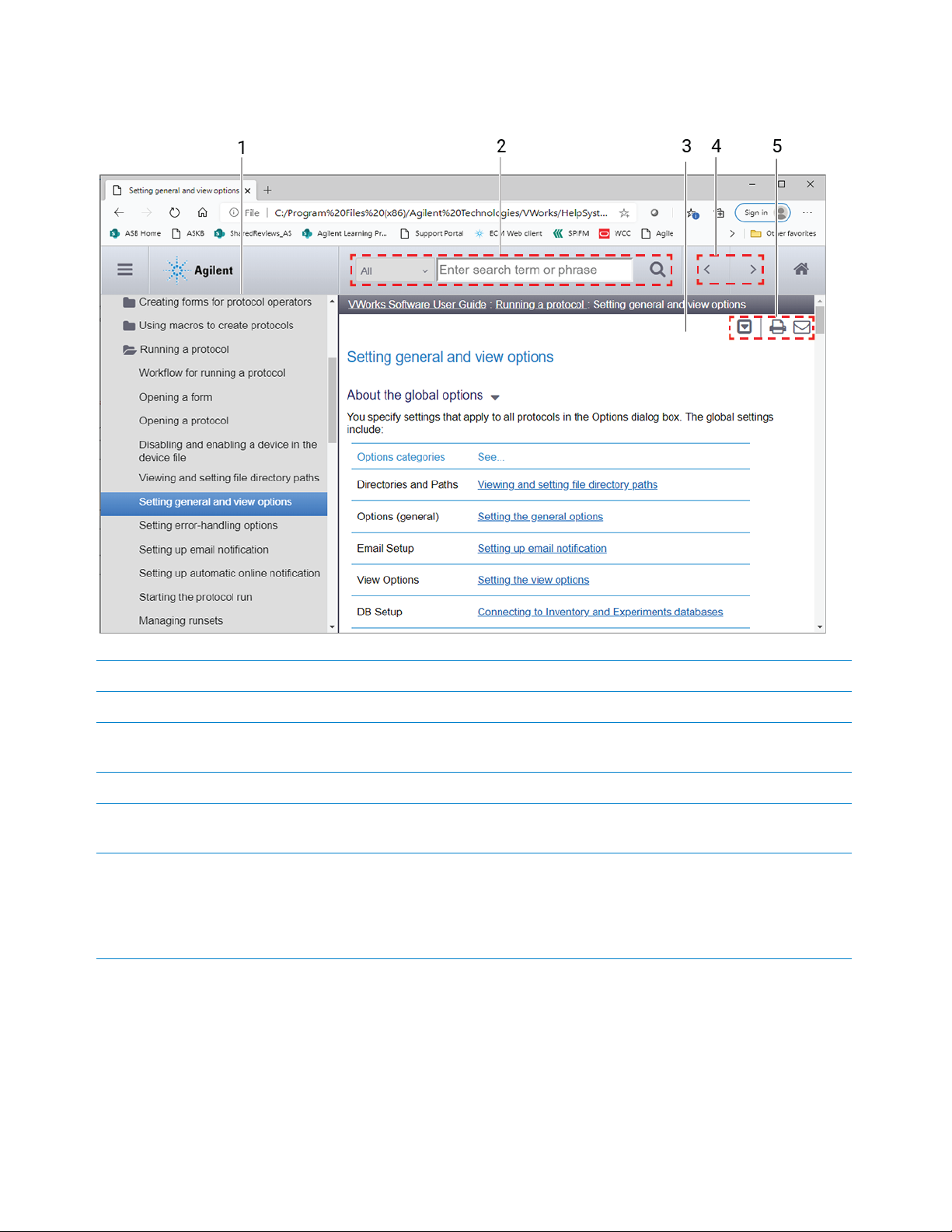
Step For this task...
1 Contents pane. Lists all the books and the table of contents of the books.
2 Search. Allows you to search the Knowledge Base (all products or selected products) using
keywords.
3 Topic area. Displays the selected online help topic.
4 Navigation buttons. Enable you to navigate through the next or previous topics listed in the Contents
tab.
5 Toolbar buttons: Enable you to:
• Expand or collapse all the sections in a topic that has drop-down headings.
• Print the topic.
• Send feedback by email for a given topic.
x
BenchCel Microplate Handler User Guide
Page 11

1 Safety guidelines
This chapter contains the following topics for the BenchCel Microplate Handler:
• “General safety information” on page 2
• “Safety and regulatory compliance” on page 3
• “Emergency stops” on page 5
• “Safety equipment and features” on page 8
• “Potential safety hazards” on page 10
1
Page 12
1 Safety guidelines
WARNING
General safety information
General safety information
Before installing and using the device
Before using the BenchCel Microplate Handler, make sure that you are properly trained
in:
• General laboratory safety
• The correct and safe operation of the BenchCel Microplate Handler
• The correct and safe operation of devices used in combination with the BenchCel
Microplate Handler
Changing or modifying the BenchCel safety equipment may prevent the safe
operation of the BenchCel Microplate Handler, invalidate its safety compliance, and
lead to personal injury or property damage. Any customer who does not use the
supplied safety equipment or who modifies the supplied safety equipment assumes
full responsibility for providing an appropriate level of safety for its operators and for
providing the applicable safety compliance marking and documentation.
General safety precautions
For the general safety precautions, the intended product use statement, and the list of
safety labels, see the Automation Solutions Products General Safety Guide.
The following figure shows the location of the safety label on the BenchCel Microplate
Handler.
Figure
Safety label location (front view and side view)
2
BenchCel Microplate Handler User Guide
Page 13

Related information
For information about... See...
1 Safety guidelines
Safety and regulatory compliance
General precautions, intended product
use statement, and list of safety labels
Regulatory compliance “Safety and regulatory compliance” on
Stopping in an emergency “Emergency stops” on page 5
Safety equipment “Safety equipment and features” on page 8
Potential hazards specific to the
BenchCel Microplate Handler
Safety and regulatory compliance
About this topic
This topic lists the compliance regulations and standards for the BenchCel Microplate
Handler.
Note: Earlier models of the BenchCel Microplate Handler may not comply with all the
standards listed in this topic.
Automation Solutions Products General
Safety Guide
page 3
“Potential safety hazards” on page 10
Compliance information
The BenchCel Microplate Handler is considered partly completed machinery as defined
by the Machinery Directive of the European Union. Therefore, the BenchCel Microplate
Handler is provided with a Declaration of Incorporation and no CE marking. The
BenchCel Microplate Handler is intended to be integrated into a conforming completed
machine (workstation). A customer in the European Union (EU) that acquires a
standalone BenchCel Microplate Handler is responsible for this integration and for CE
marking the completed workstation. The BenchCel Microplate Handler is designed to
comply with the standards listed in the table below.
Unless specifically requested by the customer, BenchCel Workstations provided by
Agilent Technologies are configured to conform to the Machinery Directive and bear
the CE marking. The Declaration of Conformity shipped with the BenchCel Workstation
describes the specific configuration that has been evaluated for conformity. Any
deviations from the specified configuration may invalidate the Declaration of
Conformity. See the Declaration of Conformity for details.
An EU customer that requests Agilent Technologies to provide a nonconforming
BenchCel Workstation must assume responsibility as the manufacturer for completing
the workstation in conformity with the applicable directives, including the Machinery
Directive. In the case of a nonconforming BenchCel Workstation, each component that
Agilent Technologies supplies will carry a Declaration of Conformity or Declaration of
Incorporation, as appropriate, to be used by the manufacturer to compile the technical
construction file.
BenchCel Microplate Handler User Guide
3
Page 14

1 Safety guidelines
Safety and regulatory compliance
Regulatory Compliance Standard
EMC
European Union EMC Directive 2014/30/EU
Canada ICES/NMB-001:2006
Australia/New Zealand AS/NZS CISPR 11:2011
RoHS
European Union RoHS Directive 2011/65/EU
Safety
European Union Machinery Directive 2006/42/EC
IEC 61326-1:2012 / EN 61326-1:2013
Low Voltage Directive 2014/35/EU
IEC 61010-1:2001 / EN61010-1:2001
IEC 61010-2-081:2001+A1:2003 /
EN 61010-2-081:2002+A1:2003
Canada CAN/CSA-C22.2 No. 61010-1-04
CAN/CSA-C22.2 No. 61010-2-081-04
USA ANSI/UL 61010-1:2004
Electromagnetic compatibility
If the BenchCel Microplate Handler causes interference with radio or television
reception, which can be determined by turning the device off and on, try one or more of
the following measures:
• Relocate the radio or television antenna.
• Move the device away from the radio or television.
• Plug the device into a different electrical outlet, so that the device and the radio or
television are on separate electrical circuits.
• Make sure that all peripheral devices are also certified.
• Make sure that appropriate cables are used to connect the device to peripheral
equipment.
• Consult your equipment dealer, Agilent Technologies, or an experienced technician
for assistance.
Changes or modifications not expressly approved by Agilent Technologies could void
the user's authority to operate the equipment.
Sound emission declaration
Sound pressure: Lp < 70 dB according to EN ISO 779:2010.
4
BenchCel Microplate Handler User Guide
Page 15

Schalldruckpegel: Lp < 70 dB nach EN ISO 779:2010.
WARNING
CAUTION
WARNING
Related information
For more information about… See…
General safety and labels “General safety information” on page 2
Safety hazards “Potential safety hazards” on page 10
Stopping in an emergency “Emergency stops” on page 5
Safety equipment “Safety equipment and features” on page 8
Emergency stops
The BenchCel Microplate Handler is equipped with an interlock circuit and emergencystop pendant.
1 Safety guidelines
Emergency stops
To avoid potential injury, Agilent recommends that you install a main emergency
stop button (Robot Disable Hub) that will stop the BenchCel robot and all other
devices on the safety interlock circuit simultaneously. In addition, all operators must
be instructed in the emergency stop procedure.
You might not be able to resume a protocol after an emergency stop. Do not use an
emergency stop to pause a run. To pause and continue a run, use the appropriate
commands in the automation software.
Stopping in an emergency
After pressing the emergency-stop button, the robot arm might have momentum and
continue to move until it comes to the end of its travel in the x-axis, z-axis, or thetaaxis or until it bumps into an obstacle. Stay clear of the robot until it stops moving.
To perform an emergency stop:
Press the red button on the pendant. The safety interlock circuit is interrupted,
disabling the robot motors. The BenchCel Microplate Handler operation stops.
BenchCel Microplate Handler User Guide
5
Page 16
1 Safety guidelines
Emergency stops
Recovering from an emergency stop
After you press the button on the emergency-stop pendant, the robot stops. One of the
following occurs:
• If you stopped a protocol run, a dialog box opens in the VWorks software.
• If you stopped the robot while diagnosing problems in BenchCel Diagnostics, a
motor-disable message appears on the screen.
Use the following procedure to recover in either case.
To recover the BenchCel device after an emergency stop:
1 If the robot dropped labware before or during the emergency stop, remove labware
that was dropped. Also remove labware at teachpoints or other locations.
2 If the BenchCel robot attempted to place labware at a location that was not free, a
collision might have occurred resulting in misalignment of the robot gripper. Check
the robot gripper alignment:
a Move the robot arms so that they are perpendicular to the x-axis.
b Make sure the bottom of the robot gripper pads are perpendicular to the robot
arms. If they are not, contact Agilent Technical Support.
Figure
Gripper alignment: (A) correct alignment, and (B) incorrect alignment
A) Correct alignment
B) Incorrect - misaligned
3 To re-enable the motors:
a At the emergency-stop pendant, turn the button clockwise to release it.
6
BenchCel Microplate Handler User Guide
Page 17

1 Safety guidelines
Emergency stops
b In the VWorks software message dialog box, select an appropriate option to
continue:
Selection Description
Diagnostics Opens the BenchCel Diagnostics dialog box. See step 4.
Note: This selection is available only when you are in the
middle of a protocol run and not while you are in BenchCel
Diagnostics.
Retry Attempts to restart the current command or task in the
run.
Ignore and
continue
Abort Aborts the current command or task in the run. Select
Ignores the current command or task and continues to the
next command or task in the protocol sequence.
Abort if you have determined that the protocol run is not
recoverable.
4 Optional. In BenchCel Diagnostics, use the available commands to manually move
If a physical crash occurred, always start BenchCel Diagnostics to home the robot and
verify teachpoints.
Related information
For information about… See…
Pausing and resuming protocol runs VWorks Automation Control User Guide
Using commands in BenchCel
Diagnostics
Complete list of available commands
in BenchCel Diagnostics
For a full description of the selections, see the VWorks Automation Control User
Guide.
the robot or other components, including:
• Release the microplate that the robot is currently holding.
• Upstack the microplate that the robot is currently holding.
• Replace the lid on the microplate.
• Home the robot.
• Verify teachpoints.
For details, see “Diagnostic tools” on page 146.
“Diagnostic tools” on page 146
“Quick reference” on page 165
Reporting a problem “Reporting problems” on page 162
BenchCel Microplate Handler User Guide
7
Page 18

1 Safety guidelines
WARNING
Safety equipment and features
Safety equipment and features
About this topic
This topic describes the safety equipment and features of the BenchCel Microplate
Handler that are required to protect operators from moving-parts hazards.
Changing or modifying the BenchCel safety equipment may prevent the safe
operation of the BenchCel Microplate Handler, invalidate its safety compliance, and
lead to personal injury or property damage. Any customer who does not use the
supplied safety equipment or who modifies the supplied safety equipment assumes
full responsibility for providing an appropriate level of safety for its operators and for
providing the applicable safety compliance marking and documentation.
Shields
Make sure the BenchCel device is enclosed in the supplied shield. The shield restricts
access to the BenchCel robot while the BenchCel Microplate Handler is operating.
Figure
BenchCel front shield
8
Additional shields may be required on devices that are integrated with the BenchCel
Microplate Handler, such as the Bravo Platform.
In addition, a light curtain connected to the safety interlock circuit may be required.
BenchCel Microplate Handler User Guide
Page 19

WARNING
To reduce the risk of injury from moving parts, ensure that the BenchCel shield and
WARNING
WARNING
the shields for any integrated devices are installed on the workstation.
Operating the Bravo Platform or Microplate Centrifuge with Loader without a safety
shield or a light curtain connected to the safety interlock circuit increases the risk of
injury.
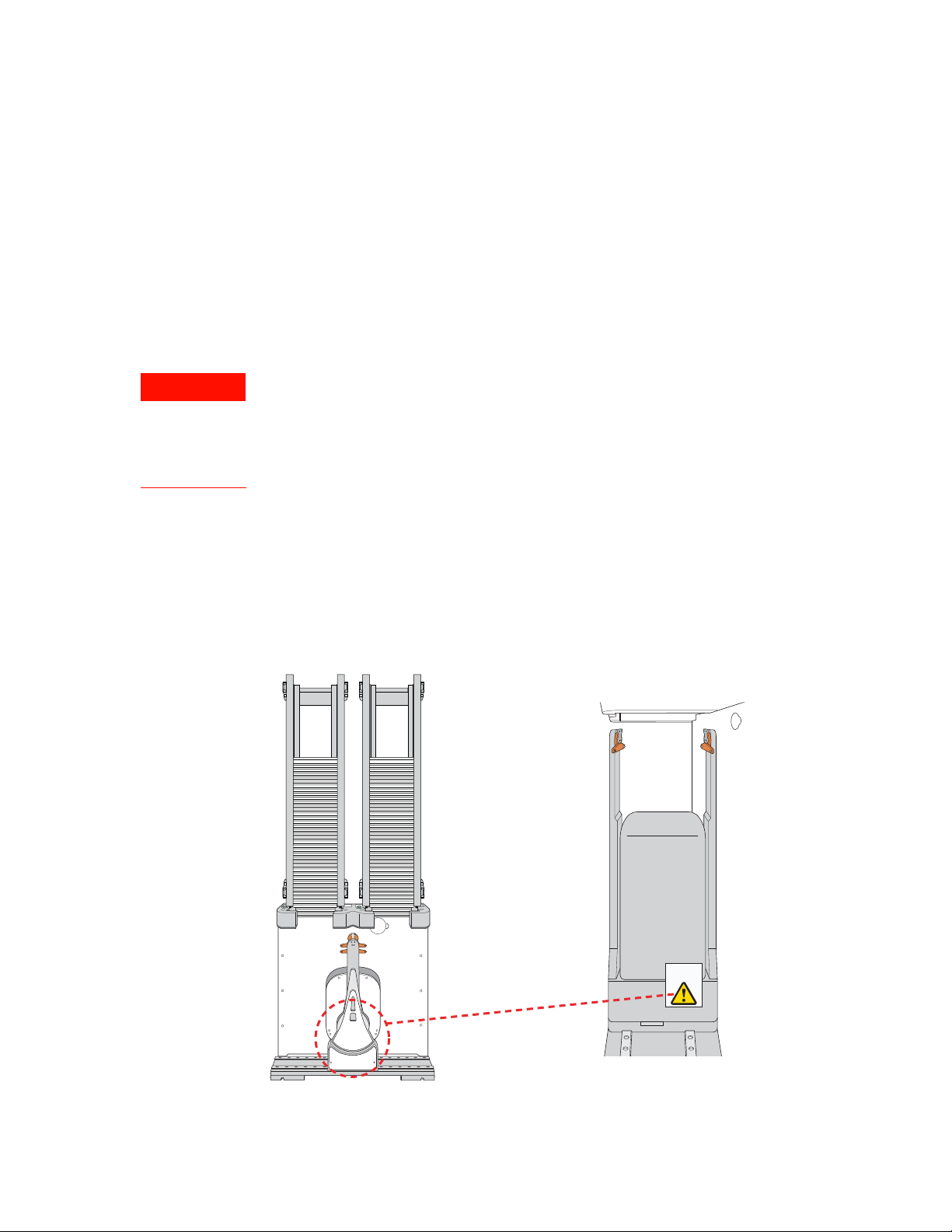
Safety interlock circuit
To avoid potential injury, Agilent recommends that you install a main emergency
stop button (Robot Disable Hub) that will stop the BenchCel robot and all other
devices on the safety interlock circuit simultaneously. In addition, all operators must
be instructed in the emergency stop procedure.
The BenchCel Microplate Handler has a safety interlock circuit that is designed to
protect operators from moving-parts hazards. The safety interlock circuit must be
closed for the device to operate. The pendant connects to the safety interlock circuit.
Pressing the red button on the pendant trips the interlock circuit and causes the motion
of the BenchCel operation to stop.
1 Safety guidelines
Safety equipment and features
Figure
When the BenchCel device is integrated with another device that has a safety interlock
circuit, such as the Bravo Platform, Agilent Technologies uses the Robot Disable Hub to
connect all the devices on the interlock circuit. Pressing the red button on a pendant or
interrupting a light curtain connected to the Robot Disable Hub will trip the safety
interlock circuit and stop all the devices connected to the circuit.
Figure
Related information
For information about… See…
Emergency-stop pendant
Robot Disable Hub
Pendants Power
Devices
Rx
Light Curtain
Tx
BenchCel Microplate Handler User Guide
Stopping in an emergency “Emergency stops” on page 5
Product compliance “Safety and regulatory compliance” on
page 3
9
Page 20

1 Safety guidelines
WARNING
WARNING
Potential safety hazards
For information about… See…
Moving parts and other hazards “Potential safety hazards” on page 10
Safety labels and general information “General safety information” on page 2
Reporting a problem “Reporting problems” on page 162
Potential safety hazards
About this topic
This topic contains precautions about potential hazards that are specific to the
BenchCel Microplate Handler. In addition to the following potential hazards, make sure
that you understand how to avoid the general hazards described in the Automation
Solutions Products General Safety Guide.
The potential hazards that you can encounter when using the BenchCel Microplate
Handler include the following:
• “Moving parts” on page 10
• “Sharp edges and pinch hazards” on page 11
• “Infrared LED injury hazard” on page 11
• “Static electricity” on page 12
• “Improper access or use” on page 12
• “Lifting hazard” on page 12
Moving parts
10
To minimize potential injury, the BenchCel device is designed to stop immediately if the
robot head hits an obstacle while it is in operation. However, be aware that the robot
moves with considerable force in the vertical or z-axis direction and could pierce your
skin with one of its grippers.
Not all circumstances can be foreseen and serious injury is possible. It is the
responsibility of every operator to follow warnings and safety labels and keep out of the
robot’s workspace whenever it is likely to move.
The BenchCel Microplate Handler has moving parts that can injure you if you deviate
from the procedures given in this guide. Keep your fingers, hair, clothing, and jewelry
away from the BenchCel Microplate Handler while it is in motion.
To avoid potential injury, do not touch the BenchCel Microplate Handler as you start
the software. The robot head moves when the device initializes.
BenchCel Microplate Handler User Guide
Page 21

WARNING
Never touch any of the moving parts or attempt to remove or add labware while the
WARNING
WARNING
WARNING
BenchCel Microplate Handler is in operation. The robot head moves with
considerable force and can cause pinching, piercing, or bruising injury if you are in
the path of the robot head or gripper.
Sharp edges and pinch hazards
Pinch hazard! Keep your fingers out of the path of the labware racks when you mount
the racks on the BenchCel device.
Use the rack handle to carry the labware racks. Do not hold a rack by the interior
edges. The interior edges might have sharp surfaces that could cause cuts if handled
improperly.
Figure Sharp surfaces on labware rack
1 Safety guidelines
Potential safety hazards
Infrared LED injury hazard
BenchCel Microplate Handler User Guide
Do not stare directly at the light-emitting diodes (LEDs) inside the stacker heads
when the device is on. Such exposure to the LEDs can cause eye injury.
Each BenchCel stacker head contains seven infrared LEDs that detect the presence of
a labware rack, microplates, and microplate notches. The LEDs are capable of
dissipating 100 mW of power. Do not stare directly at the LEDs when the BenchCel
Microplate Handler is turned on.
11
Page 22

1 Safety guidelines
CAUTION
CAUTION
WARNING
CAUTION
Potential safety hazards
Static electricity
Improper access or use
The rack-release button at the top of the stacker head on the BenchCel device is
sensitive to static electricity. Static electricity can cause a potential loss of motor
control and loss of communication with the BenchCel device. Ensure that you
discharge any potential static electricity before touching the rack-release button. To
discharge static electricity, you can touch the white painted or metal surface of the
BenchCel device before touching the rack-release button.
Improper use by an untrained user could damage the BenchCel Microplate Handler.
For example, the robot gripper could collide with a stacker if a teachpoint is not
defined properly.
Ensure that only fully trained BenchCel administrators have access to the user account
passwords.
Lifting hazard
The BenchCel device without labware racks weighs 28 – 51 kg (61.7 – 112.4 lb),
depending on the configuration. Attempting to lift or move the BenchCel device
without assistance could cause personal injury. Request assistance and use proper
lifting techniques when lifting or moving the device.
If the BenchCel Microplate Handler is incorrectly packaged and moved by someone
other than an Agilent employee, the device may be damaged. Such damage is not
covered by the warranty.
Before moving a BenchCel Microplate Handler, ensure the new location meets the
laboratory requirements.
Related information
For more information about… See…
General safety “General safety information” on page 2
Stopping in an emergency “Emergency stops” on page 5
Shields, pendants, and safety
interlock circuit
“Safety equipment and features” on page 8
12
Locations of hardware components “Hardware overview” on page 15
Site laboratory requirements “Verifying laboratory requirements” on
page 37
Reporting problems with the
BenchCel Microplate Handler
“Reporting problems” on page 162
BenchCel Microplate Handler User Guide
Page 23

2Introduction
This chapter contains the following topics:
• “BenchCel Microplate Handler description” on page 14
• “Hardware overview” on page 15
• “Integration options for workstations” on page 25
• “Labware considerations” on page 27
• “Software description” on page 29
13
Page 24

2 Introduction
BenchCel Microplate Handler description
BenchCel Microplate Handler description
Description
The BenchCel Microplate Handler is a microplate-processing automation device that:
• Stores stacks of labware (microplates, tip boxes, and tube racks) to be processed
during a protocol run.
• Moves labware to and from integrated devices such as the Bravo Platform,
PlateLoc Thermal Microplate Sealer, or Microplate Labeler for processing.
Figure
BenchCel Microplate Handler with safety shield and two labware racks
Configurations
14
The BenchCel Microplate Handler is available in three options:
• BenchCel 2R has two stackers that support two labware racks
• BenchCel 4R has four stackers that support four labware racks
• BenchCel 6R has six stackers that support six labware racks
The BenchCel Microplate Handler is included in the following standard Agilent
workstations:
• G5590A BenchCel Workstation
• G5591A Bravo BenchCel Workstation
BenchCel Microplate Handler User Guide
Page 25

Related information
WARNING
For more information about… See…
2 Introduction
Hardware overview
Agilent devices that you can integrate
in a BenchCel Workstation
Hardware component description “Hardware overview” on page 15
Automation-ready labware “Labware considerations” on page 27
Safety information “Safety guidelines” on page 1
Hardware overview
About this topic
This topic describes the hardware features of the BenchCel device. Note that the
figures in this topic show a BenchCel 2R device with two stackers that support two
labware racks. All the major components and functions are the same for the
BenchCel 4R (four stackers) and BenchCel 6R (six stackers).
Do not operate the BenchCel Microplate Handler without the safety shield. Doing so
increases the risk of injury.
“Integration options for workstations” on
page 25
BenchCel Microplate Handler User Guide
15
Page 26

2 Introduction
1
2
3
4
5
6
7
8
9
Hardware overview
Front view
Item Feature Description
1 Labware
rack
2 Stacker
head
The accessory that stores labware to be processed in a run.
For details, see “Labware racks” on page 24.
The structure at which:
• A labware rack is loaded. Two sensors inside of each
stacker head detect the presence of the racks.
• A microplate is checked for type and orientation using a
plate-presence sensor and four plate-orientation sensors.
• A microplate is lowered into the stacker grippers to begin
a run.
See “Stacker head” on page 20 for the location and detailed
descriptions of the sensors.
3 Air
pressure
regulator
The knob that you turn to adjust the air pressure inside the
device. Compressed air is used to move components inside
the stacker heads. Each regulator controls the air pressure to
the two adjacent stacker heads. For details, see “Adjusting the
stacker gripper pressure” on page 158.
4 Safety
shield
The clear panel that is installed on the front of the BenchCel
device to prevent access while it is in operation.
16
BenchCel Microplate Handler User Guide
Page 27
2 Introduction
theta-axis
+
--
Hardware overview
Item Feature Description
5 Pendant The component that is part of the safety interlock circuit,
which must be closed for the BenchCel device to operate.
Pressing the raised button on the pendant interrupts the
safety circuit and disables the robot motors. Use this method
of stopping the robot for emergencies only.
6 Rack-
release
button
7 Robot
head
The button that unlocks the rack for removal. The rack-release
button at the top of each stacker head displays different
colors to indicate the state of the stacker head:
• Green. The labware rack is installed correctly on the
BenchCel device and the microplates are unloaded. The
stack of microplates are ready for processing or you can
unlock and remove the labware rack.
• Flashing green. The labware rack is unlocked and can be
removed.
• Blue. The stack of microplates is loaded. You cannot
unlock and remove the labware rack.
• Red. The clamps are open without a rack installed. Do not
install a rack until the clamps are closed.
The component that moves horizontally along the x-axis and
vertically along the z-axis.
+
z-axis
--
--
x-axis
8 Robot
arms
Two parallel structures that are attached to and rotate about
the robot head along the theta-axis.
BenchCel Microplate Handler User Guide
+
17
Page 28
2 Introduction
Hardware overview
Item Feature Description
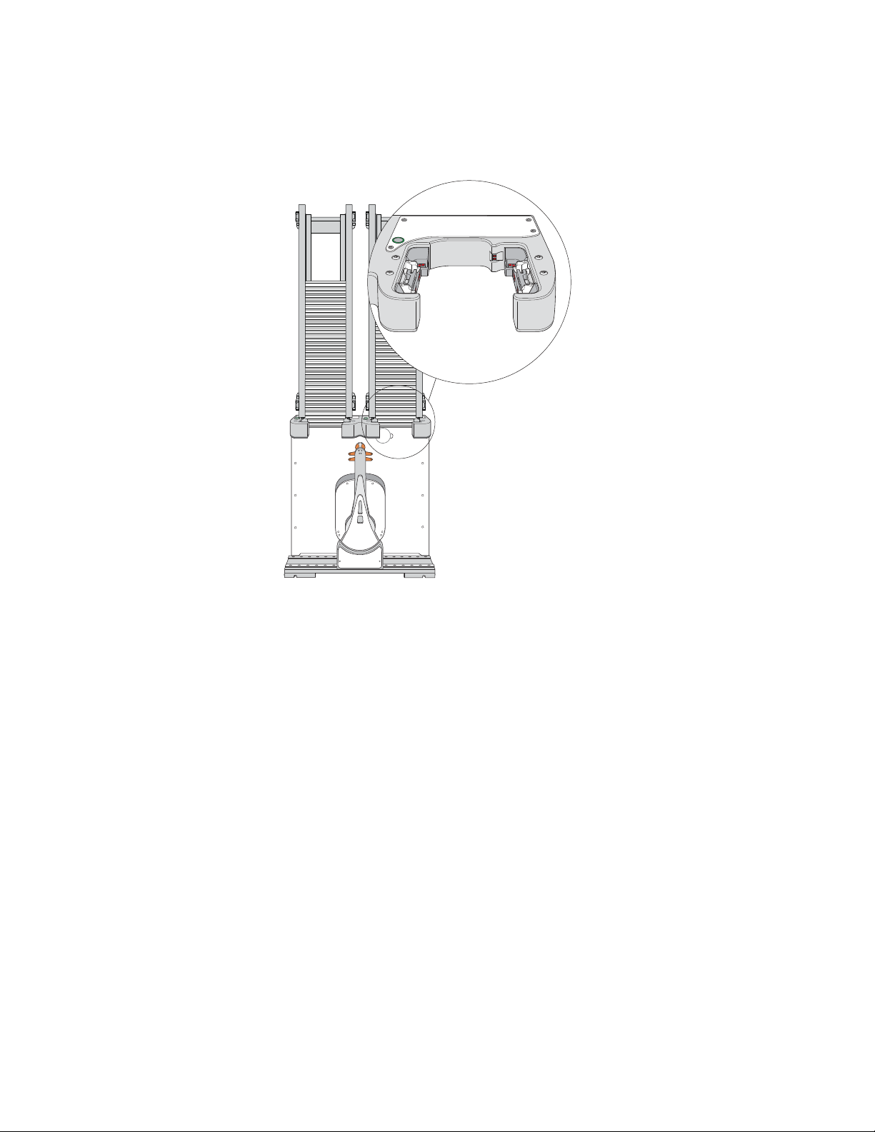
Back view
9 Robot
grippers
The structures inside the robot arms that close and open to
hold and release a microplate. Using the provided software,
you can adjust the distance between the grippers to hold a
microplate loosely or tightly.
Robot grippers
1
2
3
4
5
6
18
BenchCel Microplate Handler User Guide
Page 29

Item Feature Description
2 Introduction
Hardware overview
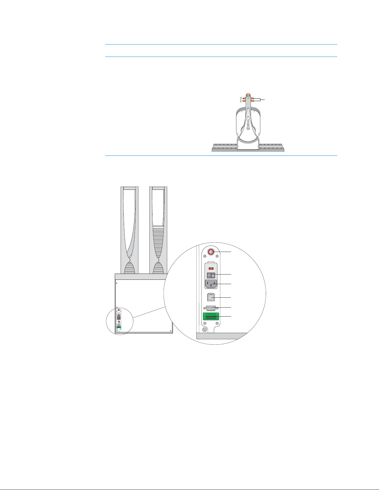
1 Air-input
fitting
2 Power
Connects the air tubing to the BenchCel device. Compressed
air is used to actuate components inside the stacker head.
Turns on or off the power to the BenchCel device.
switch
3 AC power
Connects the power cord to the BenchCel device.
entry
4 Ethernet
port
Connects the Ethernet cable from the controlling computer to
the BenchCel device to allow communication between the
computer and the device. Use this port as an alternative to the
serial connection.
5 Serial port Connects the serial cable from the controlling computer to the
BenchCel device to allow communication between the
computer and the device. Use this port as an alternative to the
Ethernet connection.
6 Pendant
port
Connects the emergency-stop pendant to the safety interlock
circuit. The connection is made either directly or through an
emergency-stop control, such as the Robot Disable Hub.
IMPORTANT The safety interlock circuit must be closed for
the BenchCel Microplate Handler to operate.
BenchCel Microplate Handler User Guide
19
Page 30
2 Introduction
Hardware overview
Stacker head
At the top of the BenchCel device are stacker heads that contain infrared sensors and
mechanical components that load and unload microplates during operation.
The following table lists and describes the various components inside the stacker head.
20
BenchCel Microplate Handler User Guide
Page 31

Feature Description
Plate-presence sensor
Rack-presence sensors
2 Introduction
Hardware overview
Plate-presence
sensor
Rack-presence
sensors
Detects the presence of a microplate in the stack. One platepresence sensor is on the back wall of each stacker head.
Detect the presence of labware racks. Two rack sensors are on
the back wall of each stacker head.
BenchCel Microplate Handler User Guide
21
Page 32

2 Introduction
A
B
C
D
E
F
G
H
I
J
K
L
M
N
O
P
1234
5678
9 101112131415161718192021222324
Notches
Plate-orientation sensor
A
B
C
D
E
F
G
H
I
J
K
L
M
N
O
P
1234
5678
9 101112131415161718192021222324
Notches
Clamps
Hardware overview
Feature Description
Plate-orientation
sensors
Detect the presence of notches in microplates. Four sensors are
in the inside corners of each stacker head. For details of how the
sensors work, see “Setting sensor thresholds” on page 99.
Clamps Close and open the grippers at the bottom of the labware rack to
hold and release microplates during loading, unloading,
downstacking, and upstacking processes. Two clamps are
inside each stacker head. Compressed air is used to open and
close the clamps.
22
BenchCel Microplate Handler User Guide
Page 33

2 Introduction
Shelves
Hardware overview
Feature Description
Shelves Provide leveling surfaces for the microplates, thus ensuring
accurate robot gripping, during the downstacking process. Two
shelves (four leveling surfaces) are inside each stacker head.
Compressed air is used to move the shelves.
BenchCel Microplate Handler User Guide
23
Page 34

2 Introduction
1
2
3
Hardware overview
Labware racks
The labware racks are available in two models:
• Front-load rack in 250-mm and 660-mm sizes
• Top-load rack in 660-mm and 860-mm sizes
Both rack models have the following basic components.
Figure
Front-load rack components
24
Item Name Description
1 Carrying handle The top-load and front-load racks have fold-down
carrying handles.
2 Tabs A pair of vertical tabs are located at the bottom on the
rack sides. The tabs insert into slots on the device
when you mount the rack onto the device.
3 Stacker grippers A gripper is located on the interior bottom of each tab.
The pair of grippers hold a microplate during the
labware loading, unloading, downstacking, and
upstacking processes. A clamp in the device opens
and closes the grippers.
BenchCel Microplate Handler User Guide
Page 35

2 Introduction
Microplate
Integration options for workstations
The following figure shows a closeup view of a labware rack, with the stacker grippers
holding a microplate. The front wall of the rack is not shown to reveal the stacker
grippers that are hidden from view.
Figure
Related information
For more information about… See…
Automation-ready labware “Labware considerations” on page 27
Software that controls the BenchCel
Microplate Handler
Safety information “Safety guidelines” on page 1
Installation requirements “Verifying laboratory requirements” on
Labware rack closeup view showing microplate held by the stacker grippers
“Software description” on page 29
page 37
Integration options for workstations
About this topic
You can integrate Agilent devices with the BenchCel Microplate Handler to create a
BenchCel Workstation. The BenchCel robot can move labware to and from these
devices as specified by the protocol you create.
This topic lists some of the devices that can be integrated with the BenchCel
Microplate Handler.
Agilent devices
The following figure shows an example of a BenchCel Workstation.
BenchCel Microplate Handler User Guide
25
Page 36

2 Introduction
Integration options for workstations
Figure
six stackers, and (
Example of BenchCel Workstation: (1) computer, (2) Bravo Platform, (3) BenchCel with
4) Labware MiniHub
The following Agilent devices can be integrated with the BenchCel Microplate Handler.
:
Item Device Description
Related information
For more information about… See…
BenchCel Microplate Handler features “Hardware overview” on page 15
Safety information “Safety guidelines” on page 1
Installation requirements “Installing BenchCel Microplate Handler” on
1 Bravo Platform Dispenses liquids.
2 Labware MiniHub Stores labware.
3 Microplate Labeler Prints barcodes and applies the
barcode labels to microplates.
4 Microplate Centrifuge with
Centrifuges microplates.
Automated Loader
5 PlateLoc Thermal Microplate
Applies seal on microplates.
Sealer
page 35
26
BenchCel Microplate Handler User Guide
Page 37

Labware considerations
Microplate
About this topic
This topic provides guidelines for selecting automation-ready labware for use in the
BenchCel Microplate Handler.
Acceptable microplates
The BenchCel device is designed to handle labware that comply with the standards
ANSI/SLAS 1-2004 (R2012) through ANSI/SLAS 4-2004 (R2012). For use of
nonconforming labware, contact Agilent Technical Support.
The BenchCel device uses gripping mechanisms to hold microplates securely and
repeatably in the labware rack and in the robot arms. The BenchCel device typically
holds the microplates halfway between the top of the microplate and the top of the
microplate skirt (5 to 10 mm above the bottom of the microplate).
In the following figure, notice the gripper-microplate contact point.
2 Introduction
Labware considerations
Figure
Lidded microplates
Microplates that do not have lids or have shallow lids (lids that do not reach the
microplate skirt) provide enough clearance to allow secure and repeatable gripping.
Microplates with deeper lids can be more challenging, because the microplate must be
held by the skirt. If the skirt is too flexible, the stacker grippers will bend the skirt. The
bent skirt can grip the microplate lid stacked beneath, inadvertently removing the lid.
Note: Some labware vendors might offer alternative lids that are shallower. Contact the
vendor for details.
Labware rack closeup view showing microplate held by the stacker grippers
BenchCel Microplate Handler User Guide
27
Page 38

2 Introduction
Labware considerations
Figure
Lidded microplate examples
Challenging microplate characteristics
Microplates that have the following characteristics might require additional setup time
to ensure repeatable performance for the BenchCel device:
• Microplate material. Although you can adjust the robot grip distance to compensate
for a microplate’s flexibility, some microplates are too soft and tend to bend in the
robot grippers or become warped after thermal cycling. (for example, low-profile
polypropylene PCR microplates).
• Manufacturing variance. Gross variations in microplate dimensions can reduce
repeatability of secure gripping. In addition, because the BenchCel device uses
reflected light to sense microplate presence and orientation, variations in the
reflective properties of the microplates can affect optimal operation.
• Microplate design. Some microplates have special features specifically designed
for particular instruments but are not optimized for the BenchCel device.
• Thermal cycling effects. Microplates that have been through thermal cycling might
become warped.
• Tall labware. Especially tall tube racks and tip boxes that are taller than 65 mm
might pose challenges in the BenchCel device. Contact Agilent Technical Support
about acceptable tall labware.
• Extra long lid. Some microplates that have lids that extend past the microplate skirt
tend to pose challenges for the BenchCel device. Contact Agilent Technical Support
for guidance.
No lid: excellent
gripper clearance
Shallow lid: good
gripper clearance
Deep lid: no gripper
clearance, must be
held by the skirt
Related information
28
For more information about… See…
Defining labware in the software VWorks Automation Control Setup Guide
Location of plate-orientation sensors “Stacker head” on page 20
How the plate-orientation sensors
work
“Setting sensor thresholds” on page 99
BenchCel Microplate Handler User Guide
Page 39

For more information about… See…
BenchCel Microplate Handler features “Hardware overview” on page 15
Safety information “Safety guidelines” on page 1
Installation requirements “Installing BenchCel Microplate Handler” on
Software description
About this topic
This topic describes the software that you can use to set up, control, and troubleshoot
the BenchCel Microplate Handler.
VWorks software 13.1.x
2 Introduction
Software description
page 35
VWorks 13.1.x enables you to:
• Set up user accounts and privileges
• Set up your devices
• Define labware, liquid classes, and pipetting techniques
• Manage labware inventory
• Create protocols and forms, and run the protocols
VWorks 13.1.x uses the Windows Registry to store records, such as labware definitions
and device profiles, and uses the local file system to store VWorks files, such as device
files and protocols.
BenchCel Microplate Handler User Guide
29
Page 40

2 Introduction
Software description
VWorks software 14.0 and later versions
VWorks 14.0 and later versions are available as VWorks Plus and VWorks Standard
editions. Both editions consist of Agilent OpenLab components and VWorks software.
VWorks Plus includes features that support compliance with Part 11 of Title 21 of the
Code of Federal Regulations (21 CFR Part 11). You use the VWorks software to control
your automation devices
OpenLab components
• Control Panel and Shared Services. Control Panel is the user interface for Shared
Services, which are set of administrative services. An administrator uses Control
Panel to configure VWorks user access, software licenses, and storage.
• Storage types. Shared Services uses a different storage type for each VWorks
edition:
– VWorks Plus. Uses Content Management to store VWorks files, records of
interest, and audit trails. The files are stored in a predefined VWorks Project
folder in the Content Management repository. A system administrator can use
the Content Browser to view and edit the project structure and contents.
– VWorks Standard. Uses the local file system. Shared Services stores the files in
a predefined VWorks Project folder.
/VWorks Projects/VWorks
Note: Unlike earlier versions, the Windows Registry is not used for storing
records, such as labware definitions and device profiles.
VWorks software
You use the VWorks software to do the following:
• VWorks Plus only. Log audit trails and manage record states
• Define labware, liquid classes, and pipetting techniques
• Manage labware inventory (storage devices only)
• Track experiments, if applicable
• Set up devices
• Create protocols and forms, and run the protocols
30
BenchCel Microplate Handler User Guide
Page 41

2 Introduction
Software description
Figure
VWorks software window
BenchCel ActiveX control
You can use the BenchCel ActiveX control instead of the VWorks software to control
the BenchCel Microplate Handler. The BenchCel ActiveX control enables the BenchCel
device to interact with a third-party lab automation system.
BenchCel Diagnostics software
Accessed through the VWorks software or the BenchCel ActiveX control, Diagnostics
enables you to do the following:
• Create and manage profiles. The software uses the information in the profile to
communicate between the BenchCel device and the controlling computer. You
create profiles using the Profiles tab in BenchCel Diagnostics when you set up the
BenchCel Microplate Handler.
BenchCel Microplate Handler User Guide
31
Page 42

2 Introduction
Software description
Figure
BenchCel Diagnostics Profiles tab
Note: In VWorks v14.0 and later versions, BenchCel Diagnostics includes an
activity log for the current session in a box at the bottom of the window. The
Profiles tab also includes a table that displays variables that were modified
since the last was last saved. The VWorks software records these events and
stores the information in the Main log. For details on the logs, see the VWorks
Automation Control User Guide.
• Set and edit teachpoints. Teachpoints are locations that the BenchCel robot will go
to and from during a protocol run. You set teachpoints using the Diagnostics
Controls tab when you set up the BenchCel Microplate Handler.
Figure
BenchCel Diagnostics Controls tab
32
BenchCel Microplate Handler User Guide
Page 43

2 Introduction
Software description
• Diagnose problems. You can use the Jog/Teach tab on the Diagnostics Controls
page to move and adjust individual hardware components. These controls are
useful for diagnosing and troubleshooting problems.
Figure
BenchCel Diagnostics Jog/Teach tab
While testing new or troubleshooting labware definitions, you can change
parameters to refine the labware definition. Diagnostics includes a Labware tab on
the Controls page, which enables you to adjust the labware definitions.
Alternatively, you can use the Labware Editor to update the labware definitions.
Figure
BenchCel Diagnostics Labware tab
BenchCel Microplate Handler User Guide
33
Page 44

2 Introduction
Software description
• Change general device settings. After diagnosing problems, you can change some
of the device settings to repair problems or to optimize operation.
Related information
For more information about... See...
Creating and running protocols in
VWorks
Figure
BenchCel Diagnostics General Settings tab
VWorks Automation Control User Guide
VWorks setup instructions VWorks Automation Control Setup Guide
Setting up profiles and teachpoints “Setup workflow” on page 64
Using Diagnostics to troubleshoot
problems
BenchCel ActiveX control BenchCel ActiveX User Guide
“Diagnostic tools” on page 146
34
BenchCel Microplate Handler User Guide
Page 45

3 Installing BenchCel Microplate Handler
This chapter contains the following topics:
• “Installation workflow” on page 36
• “Verifying laboratory requirements” on page 37
• “Unpacking BenchCel Microplate Handler” on page 42
• “Mounting the robot” on page 44
• “About integrating devices in a BenchCel Workstation” on page 47
• “Connecting the power source” on page 50
• “Connecting the pendant directly to the BenchCel device” on page 51
• “Connecting the pendant through the Robot Disable Hub” on page 53
• “Connecting and disconnecting the air source” on page 55
• “Connecting the computer” on page 57
• “Installing the shield” on page 61
35
Page 46

3 Installing BenchCel Microplate Handler
WARNING
Installation workflow
Installation workflow
About this topic.
This topic presents the sequence of installation procedures for the BenchCel Microplate
Handler. Typically, an integrated BenchCel Workstation will be installed for you.
Changing the configuration or components of the installed workstation might
invalidate the safety compliance and lead to personal injury or equipment damage.
Workflow
Step For this task… See…
1 Verify that the installation
location meets the site
requirements.
2 Unpack the computer and
connect the monitor,
power, mouse, and
keyboard.
3 Install the VWorks
software.
4 Unpack the BenchCel
device.
5 Install the BenchCel risers,
if applicable.
6 Mount the robot head on
the BenchCel device.
7 Integrate external devices. “About integrating devices in a BenchCel
8 Connect the BenchCel
Microplate Handler:
Power
“Verifying laboratory requirements” on
page 37
Manufacturer’s instructions
• VWorks Automation Control Installation
Guide (VWorks 14.0 and later)
• Software release notes (VWorks 13.1.x)
“Unpacking BenchCel Microplate Handler”
on page 42
Agilent Technical Support
“Mounting the robot” on page 44
Workstation” on page 47
“Connecting the power source” on page 50
36
Pendant • “Connecting the pendant directly to the
BenchCel device” on page 51
• “Connecting the pendant through the
Robot Disable Hub” on page 53
Air supply “Connecting and disconnecting the air
source” on page 55
Computer “Connecting the computer” on page 57
BenchCel Microplate Handler User Guide
Page 47

3 Installing BenchCel Microplate Handler
Verifying laboratory requirements
Step For this task… See…
9 Install the safety shield. “Installing the shield” on page 61
10 Install the labware racks. “Installing and uninstalling the labware
racks” on page 123
11 Install the integrated
devices.
12 Set up the BenchCel device
profile and set the
teachpoints.
Related information
For information about… See…
Installing external devices External device user documentation
Setting up the BenchCel Microplate
Handler
Defining labware and writing protocols VWorks Automation Control Setup Guide
Verifying laboratory requirements
Installation guide for the device.
“Setup workflow” on page 64
“Setting up the BenchCel device” on
page 63
Laboratory space
Laboratory table or bench requirements
Make sure the table for the BenchCel Microplate Handler has the following:
• Proximity to power and air sources
• Enough space to accommodate the complete configuration of the BenchCel
Microplate Handler, computer, monitor, pendant, and integrated devices.
• Enough strength to support the weight of the BenchCel Microplate Handler and
integrated devices without excessive shaking or movement.
• Be fixed in place, for example, casters that lock.
• Sufficient clearance on the back side of the BenchCel Microplate Handler to access
power, communication, and air tubing connections and for maintenance tasks.
• Proper height for any operator to comfortably operate the BenchCel Microplate
Handler
The table must be level in the direction of the width and the depth of the platform.
Using a traditional bubble level, the table should be leveled such that the bubble is
centered between the two limit lines of the level.
The table surface must have a thickness relative to the material that will prevent
warping when the BenchCel Microplate Handler and computer are set upon the table.
BenchCel Microplate Handler User Guide
37
Page 48

3 Installing BenchCel Microplate Handler
Verifying laboratory requirements
The table surface must be attached to the table frame.
The table frame must have:
• A leveling mechanism in the feet or casters.
• Dimensions that enable support of the table surface without overhang.
Space requirements
The minimum space requirements for your BenchCel Microplate Handler depends on
its configuration and labware rack size. The following table lists dimensions for a
BenchCel Microplate Handler in a two-, four-, or six-stack configuration.
Dimension Two stacks Four stacks Six stacks
Height, device without Risers 46.3 cm 46.3 cm 46.3 cm
Height, device with Risers (146-mm) 60.8 cm 60.8 cm 60.8 cm
Labware rack height* (250-mm,
660-mm, 860-mm)
Width 43.2 cm 86.4 cm 129.5 cm
Depth 20.3 cm 20.3 cm 20.3 cm
Weight, approximate**
without rack
with rack (660 mm, front-loading)
*Approximately 30-mm of the rack height sits down inside the BenchCel stacker head.
The overall height of a BenchCel device on risers with racks installed is as follows:
82.8 cm (250-mm rack)
126.0 cm (660-mm rack)
1438 cm (860-mm rack)
See the following figure.
**The rack weight is for the front-loading style rack and does not include liquid-filled
microplates. The weight differs slightly between the top-loading and front-loading rack
types.
———
28 kg
32.5 kg
39.5 kg
48.6 kg
51 kg
64.6 kg
38
BenchCel Microplate Handler User Guide
Page 49

3 Installing BenchCel Microplate Handler
250 mm
828 mm
1438 mm
1260 mm
660 mm
860 mm
Verifying laboratory requirements
Figure Example of BenchCel on risers with six stacks showing height requirements of 250-mm, 660-mm, and
860-mm racks
Addition of devices
If you are integrating an Agilent device or third-party device with your BenchCel
Microplate Handler, make sure you include adequate space to accommodate these
devices. See the device user documentation for space requirement information.
Electrical requirements
The BenchCel Microplate Handler has the following power requirements. For power
requirements of other devices in an integrated workstation, see the applicable device
user documentation.
Utility Requirement
Electrical 100–240 V~, 50/60 Hz
Operating AC current 5 A at 120 V~, 2.5 A at 240 V~
Fuse
Compressed air requirements
The BenchCel Microplate Handler requires the use of clean, dry, compressed air to
move pneumatic components inside the device. The compressed air can be from the
following sources:
• Centralized source (house)
• Compressed-air cylinders
• Portable pumps
5 A, 250 V, 5
× 20 mm, fast acting
BenchCel Microplate Handler User Guide
39
Page 50

3 Installing BenchCel Microplate Handler
CAUTION
CAUTION
Verifying laboratory requirements
Using oil compressors can cause oil to leak into the BenchCel Microplate Handler
and void your warranty.
Air pressure greater than 0.69 MPa (100 psi) can damage the BenchCel Microplate
Handler.
To maintain the desired air supply in the device, the BenchCel Microplate Handler
requires a source of air as follows:
Requirement Value
Quality Clean, dry, compressed
Flow rate 34.0 Lpm (1.2 cfm)
Pressure 0.65–0.69 MPa (95–100 psi)
Environmental requirements
The lab must meet the following environmental requirements.
Requirement Value
Ambient temperature
Humidity condition
Elevation 1–2000 m
Make sure the BenchCel Microplate Handler is located away from the following:
• Heat and air conditioning ducts.
• Direct sunlight.
Computer requirements
The requirements of the controlling computer depend on the lab automation software
you are using.
• VWorks 14.0 or later, see the installation guide for the software.
• VWorks 13.1.x, see the software release notes.
For third-party automation software, see the user documentation supplied with the
product.
5–40
°C
10–90%
RH, non-condensing
Networking considerations
40
The supplied computer comes with a serial port and two Ethernet ports. You can
connect the computer to the BenchCel Microplate Handler using either the serial port or
one of the Ethernet ports. You can use the second Ethernet port to connect the
BenchCel Microplate Handler User Guide
Page 51

computer to your local area network (LAN). You must provide an Ethernet cable for the
WARNING
LAN connection and make sure the lab has the proper network hookups for the
connection.
If you are supplying your own computer, consider whether you will:
• Connect the computer to the BenchCel Microplate Handler using a serial or
• Connect the computer to your LAN.
Connecting the BenchCel Microplate Handler to a company or general network can
potentially cause injury. Remote computer operators might accidentally initiate an
operation that causes the robot to move unexpectedly, possibly injuring nearby lab
personnel.
If you plan to connect the computer to the BenchCel Microplate Handler and to your
company’s LAN, the computer might require two Ethernet cards. Two Ethernet cards
allow the BenchCel Microplate Handler to operate on an isolated network.
Related information
3 Installing BenchCel Microplate Handler
Verifying laboratory requirements
Ethernet connection.
For information about… See…
Lab requirements for external devices External device user documentation
Contacting technical support “Reporting problems” on page 162
Installing the BenchCel Microplate
Handler
“Installation workflow” on page 36
BenchCel Microplate Handler User Guide
41
Page 52

3 Installing BenchCel Microplate Handler
WARNING
Unpacking BenchCel Microplate Handler
Unpacking BenchCel Microplate Handler
About this topic
This topic describes how to unpack the BenchCel Microplate Handler from the shipping
containers.
Shipping containers
The shipping containers include:
• BenchCel crate containing the BenchCel device.
• Peripherals box containing the following packages:
– BenchCel utility kit
– Pendant
– BenchCel robot head
– Safety shield with hardware
– Labware racks
• Computer box
Depending on the configuration ordered, additional packages or items can be included.
Before you start
Verify the following:
1 BenchCel utility kit contents. At a minimum, the kit contains the following:
• Power cord
• Serial and Ethernet cables, and Ethernet switch
• Tubing for air line
• Software CD-ROM
2 Site specifications. Ensure the installation site meets the requirements. See
“Verifying laboratory requirements” on page 37.
Note the dimensions of the shipping container before moving it to make sure you
have adequate clearance through doorways and passages.
3 Tools and equipment requirements. Obtain the following:
• Large screwdriver to open the shipping crate
• Hex wrenches: 5-mm and 2-mm for mounting the robot head
• Cart for moving the BenchCel device
4 Personnel requirements. Make sure two people are available to lift the BenchCel
device from the crate.
The BenchCel device without labware racks weighs 28 – 51 kg (61.7 – 112.4 lb),
depending on the configuration. Attempting to lift or move the BenchCel device
without assistance could cause personal injury. Request assistance and use proper
lifting techniques when lifting or moving the device.
42
BenchCel Microplate Handler User Guide
Page 53

Procedure
CAUTION
The packing materials and shipping container were designed to protect the device.
Packing the BenchCel device using other materials might damage the device and
void your warranty. Save the packing materials and shipping container in case you
are required to move or ship the BenchCel device.
To unpack the BenchCel Microplate Handler:
1 Use a large screwdriver to open the BenchCel device shipping container.
2 Lift the contents out of the container and set each item carefully on the lab bench
or final location where you want to install the device.
3 Remove the packing foam from the device.
4 Remove components from the plastic bags or other packing material.
5 Inspect the unpacked items.
About installing risers
The 146-mm tall risers can be installed to the underside of the BenchCel device at each
end to lift the device above the table surface. The risers are required for integrating the
BenchCel device with certain devices in a workstation. In you are integrating a
BenchCel Microplate Handler on risers, the Agilent installer will install the BenchCel
risers before mounting the robot head on the BenchCel device.
3 Installing BenchCel Microplate Handler
Unpacking BenchCel Microplate Handler
BenchCel Microplate Handler User Guide
43
Page 54

3 Installing BenchCel Microplate Handler
CAUTION
Mounting the robot
Mounting the robot
About this topic
Typically, the BenchCel Microplate Handler will be installed for you. However, this topic
provides a reference for how to mount the robot on the BenchCel device.
Procedure
Do not use the robot arms to lift the robot. Doing so could damage the arms. Ensure
that you lift the robot by the base and the head. Dropping or bumping the robot can
damage the electronics. Handle the robot carefully.
Figure Correct and incorrect lift points on the robot head
44
To mount the robot on the BenchCel device:
1 Remove the shipping bracket from the BenchCel x-axis carriage as follows:
a Refer to the following figure to locate the BenchCel x-axis carriage.
b Loosen the two large black bracket screws that prevent the x-axis carriage
from moving during shipping.
c Use a 5-mm hex wrench to remove the four screws that secure the shipping
bracket to the x-axis carriage.
d Carefully lift the shipping bracket straight up, ensuring that you do not scratch
the electronics.
BenchCel Microplate Handler User Guide
Page 55

3 Installing BenchCel Microplate Handler
Stacker head
x-axis
carriage
x-axis carriage
(closeup view)
Alignment pins
Mounting the robot
Figure
BenchCel device with shipping bracket removed from the x-axis carriage
2 Slide the x-axis carriage into position directly under a stacker head opening.
3 Inspect the x-axis carriage and ensure any cables are recessed.
4 Using the correct lift points, grasp the robot head and, carefully, lower it onto the
x-axis carriage, aligning the two holes on the robot z-column bottom with the dowel
pins on the x-axis carriage.
5 Gently slide the robot downwards. When the robot is in position, push down on it to
ensure the electronics are fully connected.
6 Gently rotate the robot arms to one side to expose the two screw holes on the
robot base. Insert the two 35-mm M6 screws and tighten to secure the robot to the
base.
Figure
BenchCel robot with rotated arms to expose screw holes in the base
7 Lift the robot head from the base to expose the remaining two screw holes in the
base. While firmly supporting the robot head, install the two 45-mm M6 screws to
finish securing the robot base to the x-axis carriage.
BenchCel Microplate Handler User Guide
45
Page 56

3 Installing BenchCel Microplate Handler
WARNING
1
2
Mounting the robot
Figure
The robot head may not remain in the up position. The robot head can drop,
potentially pinching your fingers. Ensure that you support the weight of the robot
head while it is in the up position.
BenchCel robot head in up position: (1) mounting screw holes and (2) front panel
8 Gently lower the robot head onto the base.
9 To secure the front panel to the robot base, use a 2-mm hex wrench to install the
Related information
For more information about… See…
Installation requirements “Verifying laboratory requirements” on
Installing the BenchCel Microplate
Handler
two screws.
page 37
“Installation workflow” on page 36
46
BenchCel Microplate Handler User Guide
Page 57

3 Installing BenchCel Microplate Handler
WARNING
IMPORTANT
About integrating devices in a BenchCel Workstation
About integrating devices in a BenchCel Workstation
About this topic
Typically, the BenchCel Microplate Handler, any supplied devices, and the safety
equipment in a workstation will be installed for you.
This topic provides basic integration concepts: how integration plates are used and
how to adjust device positions. The workstation layout and the device integration
procedures can vary, depending on the combination of devices you are integrating and
the desired configuration.
Before you start
Changing the configuration or components of the installed workstation might
invalidate the safety compliance and lead to personal injury or equipment damage.
Contact Agilent Technical Support if you want to install the BenchCel device on risers
or integrate a new device.
Make sure you have the following:
• The external devices you want to integrate
• Two integration plates for the BenchCel device
• Integration plate for each external device
• 4-mm hex wrench
• 3-mm hex wrench
Installing the BenchCel device integration plate
The BenchCel device integration plates have locking mechanisms that keep the
BenchCel device and any external device in position during a run. The integration plates
must be installed under the BenchCel device.
To install the BenchCel device integration plate:
1 Position the integration plates on the benchtop.
2 If risers are required in the integration, install the risers on the integration plates.
3 Place the BenchCel device on the integration plates or risers.
4 Tighten the screws to secure the device on the integration plates.
Installing the external device integration plate
BenchCel Microplate Handler User Guide
You can integrate an external device on the left or right side of the BenchCel device. For
each external device, you must install the integration plate that is specific to that
device.
47
Page 58

3 Installing BenchCel Microplate Handler
Clamp screw
Integration plate BenchCel device
About integrating devices in a BenchCel Workstation
To install the external device and integration plate:
1 Depending on whether you are integrating a device to the left or right of the
BenchCel device, loosen the left or right clamp screw using the 3-mm hex wrench.
See the following figure.
As you loosen the screw, the left or right clamp opens.
Figure
Clamp screw (left side) on BenchCel device
2 Mount the external device on its integration plate. Tighten the bolts or screws to
secure the device on the integration plate.
3 Place the external device and integration plate next to the BenchCel device.
48
Figure
External device and integration plate next to the BenchCel device
BenchCel Microplate Handler User Guide
Page 59

3 Installing BenchCel Microplate Handler
Tighten slightly
so that the plate
can still move.
About integrating devices in a BenchCel Workstation
4 Use the 3-mm hex wrench to slightly tighten the BenchCel device integration plate
clamp screw. You will not tighten the screw all the way until the devices are
correctly aligned.
Figure
Integration plate clamp screw
5 Visually inspect the position of the integrated device relative to the BenchCel
device. The two devices should be aligned along the y-axis (front-to-back direction)
so that the BenchCel robot can place a microplate on the plate stage accurately. If
the devices are not properly aligned, slide the devices along the y-axis until they
appear to be correctly aligned.
Note: You will verify and refine the alignment when you set up the teachpoints
for the external devices.
6 Repeat the procedure for each external device.
Related information
For more information about… See…
Integration options “Integration options for workstations” on
BenchCel Microplate Handler
installation requirements
External device installation
requirements
Installing the BenchCel Microplate
Handler
Setting up the BenchCel Microplate
Handler
BenchCel Microplate Handler User Guide
page 25
“Verifying laboratory requirements” on
page 37
External device user documentation
“Installation workflow” on page 36
“Setup workflow” on page 64
49
Page 60

3 Installing BenchCel Microplate Handler
WARNING
Connecting the power source
Connecting the power source
About this topic
This topic explains how to connect the BenchCel Microplate Handler to a grounded
power source.
Before you start
Make sure you have the supplied power cord.
Ensure that the power cords are in good condition and are not frayed. Use of frayed or
damaged power cords can cause injury. Use of incorrect power cords can cause
damage to the device.
Connecting the power source
To connect the BenchCel device to a grounded power source:
1 Plug one end of the power cord into the AC power entry located on the back of the
BenchCel Microplate Handler.
2 Plug the other end of the cord into an AC outlet with grounded circuit.
Related information
For more information about… See…
Figure
Connectors on the back of the BenchCel Microplate Handler
50
Electrical requirements “Verifying laboratory requirements” on
page 37
Installing the BenchCel Microplate
Handler
“Installation workflow” on page 36
BenchCel Microplate Handler User Guide
Page 61

3 Installing BenchCel Microplate Handler
IMPORTANT
Connecting the pendant directly to the BenchCel device
For more information about… See…
Setting up the BenchCel Microplate
Handler
Operating the BenchCel Microplate
Handler
“Setup workflow” on page 64
“Workflow for operating the BenchCel
Microplate Handler” on page 116
Connecting the pendant directly to the BenchCel device
About this topic
If you are integrating the BenchCel Microplate Handler with devices that are not
equipped with safety interlock circuitry, for example, the PlateLoc Sealer or the
Microplate Labeler, use the procedure in this topic to connect the emergency-stop
pendant.
Figure
Emergency-stop pendant
The pendant must be connected to close the safety interlock circuit. The circuit must
be closed for the device to operate.
If the BenchCel Microplate Handler is integrated with devices that are equipped with
safety interlock circuitry, such as the Bravo Platform, you connect the pendant through
a main emergency-stop control, such as the Robot Disable Hub. See “Connecting the
pendant through the Robot Disable Hub” on page 53.
BenchCel Microplate Handler User Guide
51
Page 62

3 Installing BenchCel Microplate Handler
Connecting the pendant directly to the BenchCel device
Procedure
To connect the pendant directly to the BenchCel device:
Connect the pendant cable to the pendant port on the back of the BenchCel device.
Related information
For more information about… See…
Stopping in an emergency “Emergency stops” on page 5
Safety interlock circuit “Safety interlock circuit” on page 9
Installing the BenchCel Microplate
Handler
“Installation workflow” on page 36
52
BenchCel Microplate Handler User Guide
Page 63

3 Installing BenchCel Microplate Handler
Connecting the pendant through the Robot Disable Hub
Connecting the pendant through the Robot Disable Hub
About this topic
Read this topic if you are integrating the BenchCel Microplate Handler with other
devices that are equipped with safety interlock circuitry, such as the Bravo Platform.
This topic describes how to connect the emergency-stop pendants for the integrated
devices through the Robot Disable Hub, which provides a main emergency-stop control
for the workstation.
Figure
Figure Robot Disable Hub, 3-Port
Emergency-stop pendant
Robot Disable Hub overview
The Robot Disable Hub can connect the interlock circuits of up to three devices and a
light curtain. Pressing the red button on a pendant connected through the Robot
Disable Hub will trip the interlock circuit, causing all the devices on the circuit to stop.
The Robot Disable Hub has the following connectors, controls, and indicators:
Figure
• Pendants connectors accommodate the BenchCel pendant and up to two
• Devices connectors accommodate the BenchCel device and up to two other
• Light Curtain connectors connect to the corresponding light curtain receiver (Rx)
• Power status indicator lights green when the unit is connected to power.
BenchCel Microplate Handler User Guide
Robot Disable Hub connections (front and back views)
additional pendants.
devices with interlock circuits.
and transceiver (Tx) cables.
53
Page 64

3 Installing BenchCel Microplate Handler
IMPORTANT
Devices
Pendants Power
Light Curtain
Rx
Tx
00220
Bravo
Back
00220c
2
1
3
4
5
6
7
Connecting the pendant through the Robot Disable Hub
• Power entry port connects to the supplied 24W power adapter, which in turn
connects to the power cord.
• Light Curtain Enable/Bypass switch enables or disables the light curtain. You set the
switch to Bypass during the installation. After installing the light curtain and
connecting all the devices, you set the switch to Enable.
Any unused Pendants connectors require E-stop jumpers to close the interlock circuit.
Example of connections using Robot Disable Hub
The following figure and table provide an example of connecting the BenchCel device
and the Bravo Platform through the Robot Disable Hub.
54
Item Description Connects from Connects to Robot
1 Extension cable Bravo pendant
port
Disable Hub
Devices connector
2 Pendant cable Pendant 1 Pendants connector
3 Pendant cable Pendant 2 Pendants connector
4 Extension cable BenchCel pendant
port
Devices connector
5 Jumper Jumper Pendants connector
BenchCel Microplate Handler User Guide
Page 65

3 Installing BenchCel Microplate Handler
WARNING
Connecting and disconnecting the air source
Item Description Connects from Connects to Robot
6,7Light curtain transmitter and
receiver cables
(not shown)
Bravo Light
Curtain
Related information
For more information about… See…
Stopping in an emergency “Emergency stops” on page 5
Safety interlock circuit “Safety interlock circuit” on page 9
Installing the BenchCel Microplate
Handler
“Installation workflow” on page 36
Connecting and disconnecting the air source
Disable Hub
Light Curtain
connectors
About this topic
Compressed air is used to move parts inside the BenchCel Microplate Handler. This
topic explains how to connect the BenchCel Microplate Handler to the air source and
check the connections for leaks before use.
Before you start
Make sure you have the supplied air tubing.
Working with open, charged air lines can result in injury. Turn off the compressed air
line when disconnecting or reconnecting devices that use compressed air. Contact
your facilities department or Agilent Technical Support with questions about setting
up the air line.
Connecting the air source
To connect the BenchCel device to the air source:
1 Turn off the air at the source (house, cylinder, or pump).
2 Connect one end of the air tubing to the air source (house, cylinder, or pump), and
then connect the free end of the tubing to the quick disconnect fitting at the airinput port.
To connect the tubing, push the end of the tubing into the quick disconnect fitting
at the air source and on the back of the BenchCel Microplate Handler.
BenchCel Microplate Handler User Guide
55
Page 66

3 Installing BenchCel Microplate Handler
CAUTION
Connecting and disconnecting the air source
Figure
Air tubing connection on the back of the BenchCel Microplate Handler
Checking the air connections
To check the air connections:
1 With the air source turned off, gently tug the air tubing at each connection.
If you feel resistance at the connection, the tubing has been properly installed.
2 Turn on the air at the source (house, cylinder, or pump).
3 Listen near each connection for hissing sounds that might indicate a leak.
If you hear hissing sounds, turn off the air at the source, check and tighten the
connections, and then turn on the air again. If the problem persists, contact your
facilities department or Agilent Technical Support.
To air source (house,
cylinder, or pump)
Disconnecting the air source
Before moving or shipping the BenchCel Microplate Handler and before performing
maintenance or cleaning, disconnect the air tubing.
Do not pull the tubing out of the orange quick-disconnect fitting. Doing so can
damage the fitting.
To disconnect the air tubing from the BenchCel device
1 Turn off the air at the source (house, cylinder, or pump).
2 Push and hold the locking collar against the fitting, and then gently pull the air
tubing out.
Note: Alternatively, you can use the SMC Pneumatics tool (TG-2) to aid in this
task. See the manufacturer’s documentation for use instructions. Contact your
local SMC parts supplier for ordering details.
56
BenchCel Microplate Handler User Guide
Page 67

3 Installing BenchCel Microplate Handler
Push and hold the locking collar.
Gently pull out the tubing.
Connecting the computer
Related information
For more information about... See...
Air-source requirements “Verifying laboratory requirements” on
How to set up the BenchCel Microplate
Handler
How to operate the BenchCel
Microplate Handler
Figure
Quick-disconnect fitting (close-up view)
page 37
“Setup workflow” on page 64
“Workflow for operating the BenchCel
Microplate Handler” on page 116
Connecting the computer
About this topic
This topic explains how to connect the controlling computer to the BenchCel
Microplate Handler.
Before you start
Make sure you have the following:
• Ethernet cable (supplied) or RS-232 DB9 serial cable
• Ethernet switch (supplied) for Ethernet connections only
Connecting the controlling computer
You can connect the computer to the BenchCel Microplate Handler in one of the
following ways:
• Serial connection. You can use the supplied RS-232 DB9 serial cable to connect the
computer to the BenchCel Microplate Handler.
BenchCel Microplate Handler User Guide
57
Page 68

3 Installing BenchCel Microplate Handler
Connecting the computer
• Ethernet connection. You can use the supplied Ethernet cable to connect the
computer to the BenchCel Microplate Handler. The Agilent configured computer
has two Ethernet ports. You can use one port to connect to the BenchCel
Microplate Handler and the other to connect to your company network.
To connect the controlling computer to the BenchCel device:
1 Turn off the computer.
2 Serial connection only. Do the following:
a Connect the female end of the serial cable to a COM port on the controlling
computer. Note the number of the COM port. You will provide this number in
the software.
b Connect the male end of the serial cable to the serial port on the back of the
BenchCel Microplate Handler.
Figure
Serial connector on the BenchCel Microplate Handler (back view)
3 Ethernet connection only. Do the following:
a Connect one end of the Ethernet cable to the back of the BenchCel device.
b Connect the free end of the Ethernet cable to any available port on the Ethernet
switch.
58
BenchCel Microplate Handler User Guide
Page 69

3 Installing BenchCel Microplate Handler
WARNING
Connecting the computer
Figure
Ethernet connector on the BenchCel Microplate Handler (back view)
Configuring the computer network card (Ethernet connection only)
The computer configured by Agilent Technologies is already set up to communicate
with the BenchCel Microplate Handler. No change to the network card IP address is
required.
If you are using a computer that was not configured by Agilent Technologies, make
sure the value of the network card IP address and subnet mask are as follows:
• IP address: 192.168.0.1
• Subnet mask: 255.255.255.0
Connecting the BenchCel Microplate Handler to a company or general network can
potentially cause injury. Remote computer operators might accidentally initiate an
operation that causes the robot to move unexpectedly, possibly injuring nearby lab
personnel.
If your computer will be connected to your LAN, make sure the computer has a second
network card. The second network card can have a dynamic IP address.
Connecting the computer to external devices (Ethernet connection only)
To connect the external devices to the controlling computer:
1 Connect one end of the Ethernet cable to the Ethernet port on the external device.
See the device user documentation for details.
2 Connect the free end of the Ethernet cable to any available port on the Ethernet
switch.
BenchCel Microplate Handler User Guide
59
Page 70

3 Installing BenchCel Microplate Handler
Connecting the computer
Related information
For more information about… See…
The controlling computer requirements “Verifying laboratory requirements” on
The Ethernet switch The Ethernet switch user documentation
IP addresses The Microsoft Windows user
page 37
documentation
Installing the BenchCel Microplate
Handler
Setting up the BenchCel Microplate
Handler
Operating the BenchCel Microplate
Handler
“Installation workflow” on page 36
“Setup workflow” on page 64
“Workflow for operating the BenchCel
Microplate Handler” on page 116
60
BenchCel Microplate Handler User Guide
Page 71

Installing the shield
WARNING
About this topic
This topic explains how to install the safety shield on the front of the BenchCel
Microplate Handler. Additional shields may be required depending on the workstation
configuration. Typically, the BenchCel Microplate Handler and workstation safety
equipment will be installed for you.
Changing the configuration or components of the installed workstation might
invalidate the safety compliance and lead to personal injury or equipment damage.
Before you start
Make sure you have the following:
• 3-mm hex wrench
• Low-head M5 screws (supplied)
• 1 shield for each pair of stackers
For example, a BenchCel Microplate Handler with six stackers requires three
shields, as the following figure shows.
3 Installing BenchCel Microplate Handler
Installing the shield
BenchCel Microplate Handler User Guide
61
Page 72

3 Installing BenchCel Microplate Handler
Top view - back
Insert screws
Installing the shield
Procedure
To install the safety shield:
1 Place the safety shield on the front of the BenchCel Microplate Handler centered
between the pair of stackers. The ledge of the shield should sit on the top of the
device.
2 Insert the four M5 screws into the shield.
Figure
Safety shield on BenchCel Microplate Handler with two stackers (top view)
3 Tighten the screws using the M3 hex wrench.
4 Repeat steps 1 to 3 for each pair of stackers on the BenchCel Microplate Handler.
Related information
62
For more information about… See…
Safety shield description “Hardware overview” on page 15
Safety information “Safety guidelines” on page 1
Installing the BenchCel Microplate
Handler
Setting up the BenchCel Microplate
Handler
Operating the BenchCel Microplate
Handler
“Installation workflow” on page 36
“Setup workflow” on page 64
“Workflow for operating the BenchCel
Microplate Handler” on page 116
BenchCel Microplate Handler User Guide
Page 73

4 Setting up the BenchCel device
This chapter explains how to set up the BenchCel Microplate Handler for operation.
This chapter contains the following topics:
• “Setup workflow” on page 64
• “Starting up and shutting down” on page 66
• “Creating BenchCel device in the VWorks software” on page 68
• “Opening BenchCel Diagnostics” on page 73
• “Creating profiles” on page 76
• “Initializing the device” on page 82
• “Setting and managing teachpoints” on page 84
63
Page 74

4 Setting up the BenchCel device
Setup workflow
Setup workflow
About this topic
This topic presents the workflow for setting up the BenchCel Microplate Handler for
operation.
Before you start
Before setting up the BenchCel Microplate Handler, you should already have definitions
for the labware you want to use. For instructions on how to define labware in the
VWorks software, see the VWorks Automation Control Setup Guide.
Before setting teachpoints (step 7 in the setup workflow), you should also adjust the
BenchCel sensor thresholds for each type of labware that you use. For details, see
“Setting sensor thresholds” on page 99.
Workflow
The following table presents the steps for setting up the BenchCel Microplate Handler.
After setting up the BenchCel Microplate Handler for the first time, you will not likely
change any of the settings in the procedure unless you add a device, replace a device, or
move the BenchCel Microplate Handler.
64
BenchCel Microplate Handler User Guide
Page 75

Step For this task… See…
Set and edit teachpoints
for external devices.
Write protocols.
Create a profile for
each external device.
Create a profile.
Create a device file and add the
BenchCel device in VWorks.
Add external devices
to the device file.
Start up the workstation.
Set the sensor thresholds
for your labware.
4 Setting up the BenchCel device
Setup workflow
1
“Starting up and shutting down” on page 66
2 “Creating BenchCel device in the VWorks software” on
page 68
3 “Creating profiles” on page 76
4 User documentation for the devices
5 User documentation for the devices
6 “Setting sensor thresholds” on page 99
7 “Setting and managing teachpoints” on page 84
8 VWorks Automation Control User Guide
Related information
BenchCel Microplate Handler User Guide
For more information about… See…
Installation procedures “Installation workflow” on page 36
Operating the BenchCel Microplate
Handler
“Workflow for operating the BenchCel
Microplate Handler” on page 116
Troubleshooting problems “Maintenance and troubleshooting” on
page 129
65
Page 76

4 Setting up the BenchCel device
WARNING
IMPORTANT
Starting up and shutting down
Starting up and shutting down
About this topic
This topic explains how to start up and shutdown the BenchCel Microplate Handler.
Starting up the device
To avoid potential injury do not touch the BenchCel Microplate Handler as you start
the software. The robot head moves when the device initializes.
The BenchCel safety interlock circuit must be closed for the device to operate.
To start up the BenchCel Microplate Handler:
1 On the back of the BenchCel Microplate Handler, press the power switch to the on
(I) position.
Figure
Every time you turn on the BenchCel Microplate Handler, the robot homes (the
robot is sent to the factory-defined home position for each axis of motion). If the
BenchCel robot does not home, make sure power to the robot has been restored.
(See “Recovering from an emergency stop” on page 6 to reset the emergency-stop
button.) If the button has been reset and the robot still does not home, turn off the
device, check the connections, and turn it on again.
Power switch on the BenchCel Microplate Handler (back)
2 Turn on all other devices integrated with the BenchCel Microplate Handler. See the
device user documentation for instructions.
3 Turn on the compressed air supply to the BenchCel Microplate Handler.
66
BenchCel Microplate Handler User Guide
Page 77

4 Turn on the controlling computer. See the user documentation from the computer
manufacturer.
5 To start the VWorks software, do one of the following:
• Double-click the shortcut icon on the Windows desktop
• Go to the Windows start menu () > All Apps > Agilent Technologies >
VWorks.
Shutting down the BenchCel Microplate Handler
Shut down the BenchCel Microplate Handler if you intend to:
• Leave it unused for a long period of time.
• Service the device.
• Move it to another location.
To shut down the BenchCel Microplate Handler:
1 Follow the post-run clean-up procedure after the last protocol run. See “Cleaning up
after a protocol run” on page 132.
2 Exit the VWorks software.
3 If you use devices that require a vacuum pump, turn off power at the pump if the
pump module has an on/off switch.
4 Turn off the compressed air to the BenchCel Microplate Handler and other devices.
5 Turn off the BenchCel Microplate Handler. To do this, on the back of the device,
press the power switch to the off (O) position.
4 Setting up the BenchCel device
Starting up and shutting down
Figure
Power switch on the BenchCel Microplate Handler (back)
6 Turn off other devices in the BenchCel Microplate Handler.
BenchCel Microplate Handler User Guide
67
Page 78

4 Setting up the BenchCel device
Creating BenchCel device in the VWorks software
Related information
For information about… See…
Setting up the BenchCel Microplate
Handler
Cleaning up after a protocol run “Cleaning up after a protocol run” on
Troubleshooting startup or shutdown
problems
“Setup workflow” on page 64
page 132
“Maintenance and troubleshooting” on
page 129
Creating BenchCel device in the VWorks software
About this topic
Read this topic if you are an administrator responsible for managing Agilent devices
that are controlled by the VWorks software. This topic describes how to add and delete
new BenchCel devices in the VWorks software.
The VWorks software uses the information in a device file to communicate with and
operate devices within the lab automation system.
• If your computer was configured by Agilent Technologies. The correct device
configuration is already set up for communication with the BenchCel Microplate
Handler. You are not required to create a new BenchCel device in the software
unless you want to reference different profiles, integrate additional devices with the
workstation, or change the rack size. To establish communication, you must
initialize the device.
• If you configured your own computer. You must add a device in the VWorks
software for the BenchCel Microplate Handler. You must also add devices in the
software for any devices that are physically integrated with the workstation.
For detailed information about device files and associations with profiles, teachpoints,
and labware definitions, see the VWorks Automation Control User Guide. For
instructions on how to add third-party devices, see the Device Driver User Guide.
Devices and device files defined
A device is an item in your lab automation system that has an entry in a VWorks device
file. A device can be a robot, an instrument, or a location in a lab automation system
that can hold a piece of labware.
The device file (*.dev) stores information for all the devices in an integrated system,
including:
• Type of device (for example, BenchCel device)
• Device configuration information (for example, approach height, allowed or
prohibited labware, and so on)
• Profile to use
68
BenchCel Microplate Handler User Guide
Page 79

Creating a device file
If you are setting up the BenchCel Microplate Handler for the first time, you will create a
device file. You add the BenchCel device and the external devices to the device file.
To create a device file:
1 Log in to the VWorks software as an Administrator.
2 In the VWorks window, choose File > New > Device.
3 Choose File > Save. In the Save File As dialog box, type a file name (*.dev), select the
4 Setting up the BenchCel device
Creating BenchCel device in the VWorks software
A Device File tab appears in the VWorks window.
storage location, and click Save:
4 VWorks Plus only. If an audit trail is being logged for records in the development
state, the Audit Comment dialog box opens. Select or type the audit comment, and
then click OK.
Adding the device to a device file
Before you begin:
• Ensure that any devices are physically networked to the computer.
• Turn on the devices.
To add devices to a device file:
1 In the VWorks window, verify that the correct device file is open.
To open a device file, choose File > Open > Device. In the Open File dialog box,
locate and select your device file (*.dev), and then click Open.
2 In the Available Devices area, double-click the BenchCel icon. Or, drag the BenchCel
icon to the Device File tab.
BenchCel Microplate Handler User Guide
69
Page 80

4 Setting up the BenchCel device
IMPORTANT
Creating BenchCel device in the VWorks software
Note: To show or hide the list of available devices, choose View > Available
Devices.
3 In the Device File tab, select the BenchCel-n icon.
4 Under BenchCel Properties, type a Name for the device. By default, the software
assigns BenchCel-n, and increments the number for each BenchCel device that you
add.
To identify the specific BenchCel, the device name should include the device serial
number.
5 In the Profile list, select a profile for the device.
If the Profile list is empty, open BenchCel Diagnostics and create a profile. Then
return to the Profile list under BenchCel Properties and select the new profile.
70
To use different configurations of the same device in different protocols, you can save
time by creating a different device file for each configuration. For example, if you
change a pipette head on a pipettor, you can simply open the device file that contains
the device with the appropriate profile instead of editing the profile selection in the
device file.
6 On the Device File tab, expand the BenchCel device icon to show the list of stackers,
and then click the Stacker 1 icon. The corresponding stacker properties appear.
BenchCel Microplate Handler User Guide
Page 81

4 Setting up the BenchCel device
IMPORTANT
Creating BenchCel device in the VWorks software
Set the desired values for the following properties. Use the default values for the
remaining properties.
Property Description
Allowed/prohibited
labware
Optional. Click if you want to specify labware
restrictions for this location. The Allowed/prohibited
labware dialog box appears. For details on the labware
classes, see the VWorks Automation Control Setup Guide.
Note: If the button is not visible, click the empty field.
Stack Height Type the maximum height (mm) of the rack you are
using at this location. For example, type 660 if you are
using a 660-mm tall rack.
Do not change the default value of the Teachpoint for robot BenchCel property. For
example, the stacker 1 teachpoint identity is 1, the identity of stacker 2 is 2, and so
forth.
Repeat this step for each stacker.
7 Select File > Save.
If you are creating a new device file, the Save File As dialog box appears so that you
can specify a name and location for your device file (*.dev).
Alternatively, you can select File > Save All to save the device file and the current
protocol file at the same time.
8 VWorks Plus only. If an audit trail is being logged, the Audit Comment dialog box
opens. Select or type the audit comment, and then click OK.
BenchCel Microplate Handler User Guide
71
Page 82

4 Setting up the BenchCel device
Creating BenchCel device in the VWorks software
Specifying BenchCel accessibility at other devices
For any device in the workstation that the BenchCel robot will access, use the following
procedure to set the Teachpoint for robot Agilent BenchCel property in the device file
after you set the BenchCel teachpoint at the given device.
To set the Teachpoint for robot Agilent BenchCel property at a device:
1 In the VWorks window, open the device file that contains the BenchCel robot.
2 In the Devices area, click the location in the device that the BenchCel robot will
access.
For example, if the device file contains the BenchCel and Bravo devices, click the
Bravo deck location that the BenchCel robot will access.
3 In the Location Properties for the selected location, click the setting for the
Teachpoint for robot Agilent BenchCel property.
In the following example, the BenchCel robot will transfer labware to and from
Bravo deck location 3. In the Bravo Location Properties for deck location 3, the
Bravo 3 teachpoint is selected. The teachpoint name, Bravo 3, is assigned when
this teachpoint is set in BenchCel Diagnostics.
72
4 Select File > Save to save the change to the device file.
5 VWorks Plus only. If an audit trail is being logged, the Audit Comment dialog box
opens. Select or type the audit comment, and then click OK.
BenchCel Microplate Handler User Guide
Page 83

Related information
For information about… See…
VWorks software VWorks Automation Control User Guide
4 Setting up the BenchCel device
Opening BenchCel Diagnostics
Setting up BenchCel Microplate
Handler
Profiles “Creating profiles” on page 76
Teachpoints “Setting and managing teachpoints” on
Opening BenchCel Diagnostics
About this topic
To establish communication between the host computer and the device, you initialize
the device. You can initialize the device in the following ways:
• Diagnostics. To control the device using the Diagnostics software.
• VWorks window. To use VWorks to control the device, for example, to run a
protocol, you initialize the devices in the VWorks window.
This topic describes what happens during initialization.
“Setup workflow” on page 64
page 84
Procedure
To open Diagnostics:
1 In the VWorks window, ensure that the correct device file is open.
To open a device file, choose File > Open > Device, and then select the appropriate
device file (*.dev) in the Open File dialog box.
2 In the Devices area of the opened device file tab, highlight the device icon, and then
click Device diagnostics.
Alternatively, you can double-click the device icon.
BenchCel Microplate Handler User Guide
73
Page 84

4 Setting up the BenchCel device
Opening BenchCel Diagnostics
The device’s diagnostics dialog box opens.
Figure BenchCel Diagnostics window with Profiles page displayed
74
Note: For VWorks 14.0 and later versions, the Profiles page contains log areas.
BenchCel Microplate Handler User Guide
Page 85

Related information
For information about… See…
VWorks software VWorks Automation Control User Guide
4 Setting up the BenchCel device
Opening BenchCel Diagnostics
Setting up BenchCel Microplate
Handler
Profiles “Creating profiles” on page 76
Teachpoints “Setting and managing teachpoints” on
BenchCel Diagnostics features “Diagnostic tools” on page 146
“Setup workflow” on page 64
page 84
BenchCel Microplate Handler User Guide
75
Page 86

4 Setting up the BenchCel device
IMPORTANT
CAUTION
Creating profiles
Creating profiles
About this topic
The computer configured by Agilent Technologies already has the correct profile to
communicate with the BenchCel Microplate Handler. A new BenchCel profile is not
required unless you want to set up unique communication settings or use a different
teachpoint file.
If you are using a computer other than one configured by Agilent Technologies, you
must create a BenchCel profile. This topic describes how to create BenchCel profiles.
You must also create profiles for devices that are integrated with the BenchCel
Microplate Handler. For instructions on how to create the profiles for other Agilent
devices, see the corresponding device user documentation. For instructions on how to
create profiles for a third-party device, see the applicable device driver user guide.
Profiles
Each BenchCel Microplate Handler you install requires a unique profile, which enables
unique communication settings.
A profile is a collection of settings that manages how you connect to devices. The
software stores each profile in a device profile file (.xml).
Note: VWorks software version 13.1.x and earlier versions use the Windows Registry to
store the device profile.
A BenchCel profile does the following:
• Specifies the port used to establish communication between the BenchCel
Microplate Handler and the controlling computer.
• References a teachpoint file. For a description of teachpoint files, see “Setting and
managing teachpoints” on page 84.
• Specifies the number of stackers for the BenchCel Microplate Handler.
You use the BenchCel Diagnostics software to create and manage profiles.
Note: The profile is referenced by a device file. For information about device files, see
“Creating BenchCel device in the VWorks software” on page 68. For a detailed
description of the relationships between the device file, profile, and teachpoint file, see
the VWorks Automation Control User Guide.
Creating BenchCel profiles
Each profile can be used by multiple protocols. Deleting, renaming, or changing the
parameters for a profile based on one protocol can invalidate other protocols that
use the same profile.
76
Note: Unless you login to the VWorks software as an Administrator or Technician, only
the Profile list and the Initialize this profile button are available in the Profile
Management area of the Profiles page.
BenchCel Microplate Handler User Guide
Page 87

4 Setting up the BenchCel device
Creating profiles
To create a BenchCel profile:
1 Open BenchCel Diagnostics.
2 On the Profiles page, click Create a new profile.
3 In the Create Profile dialog box, type a name, and click OK. Use a profile name that
identifies the specific configuration, for example, you can use the device serial
number.
The change appears in the log area at the bottom of the page. For a description of
this area, see “About the profile logs” on page 80.
VWorks Plus only. If an audit trail is being logged for records in the development
state, the Audit Comment dialog box opens. Select or type the audit comment, and
then click OK.
4 In the Settings area, select one of the following:
• Ethernet connection. Select This BenchCel is connected via ethernet, and
proceed to step 5.
• Serial connection. Select This BenchCel is connected via serial, and go to step 6.
5 Ethernet connection only. Click Find available device to select the device to
associate with the profile. In the Discovered BioNet Devices dialog box that opens:
a Select the correct Ethernet adapter for the device connection. A list of devices
appear.
b In the list of devices that appear, select the BenchCel device. If you have
multiple BenchCel devices on the network, use the MAC Address to identify the
BenchCel device you want. To successfully communicate with the BenchCel
device, the Status column must display New or Matched for the device.
BenchCel Microplate Handler User Guide
77
Page 88

4 Setting up the BenchCel device
IMPORTANT
Creating profiles
Note: To determine the MAC address, you can turn off all other BenchCel
devices so that only one appears in the Discovered BioNet Devices dialog
box.
c Click OK.
6 Serial connection only.
a Select the COM port number on the controlling computer.
b Select Use flow control to stop the flow of data from the computer before it
overruns the device communication buffer. This option helps to optimize
communication over the serial connection.
78
7 If you want to create a profile for a BenchCel Microplate Handler that has a different
number of stacks than the one connected to the controlling computer, set the
Number of stacks value.
During initialization, the software automatically detects the actual number of stacks on
the BenchCel Microplate Handler. If this number differs from the number specified by
the profile, an error message appears and gives you the option to Abort, Retry, or Ignore.
If you click Ignore, the software overwrites the Number of stacks value with the actual
number of stacks.
8 Make a backup copy of the teachpoint file. If the original teachpoint file becomes
lost or damaged, you can use the backup copy instead of resetting all the
teachpoints and creating a new file.
a In the Teachpoint File area, click New.
b In the Save the Teachpoint File dialog box (VWorks 14.0 or later) or the Save As
dialog box (VWorks 13.1.x), locate the teachpoint file for your profile.
BenchCel Microplate Handler User Guide
Page 89

4 Setting up the BenchCel device
CAUTION
Creating profiles
Note: The default teachpoint file name is Teachpoints_<profilename>.xml,
where <profilename> is the name of the profile.
c Append the teachpoint file name with the word backup, and then click Save.
Note: The Teachpoint File area displays the file storage location.
9 In the Teachpoint File area, click , and in the Select a Teachpoint File dialog
If the teachpoint file was copied from another computer, you must verify the
teachpoints for the new profile before using the profile.
BenchCel Microplate Handler User Guide
VWorks Plus only. If an audit trail is being logged for records in the development
state, the Audit Comment dialog box opens. Select or type the audit comment, and
then click OK.
box, locate and select your original teachpoint file, and then click Open.
You will edit the teachpoints in this file in another procedure.
79
Page 90

4 Setting up the BenchCel device
CAUTION
Creating profiles
10 Click Update this profile to save the changes.
VWorks Plus only. If an audit trail is being logged, the Audit Comment dialog box
opens. Select or type the audit comment, and then click OK.
11 To establish communication with the BenchCel Microplate Handler, click Initialize
this profile.
To prevent a potential hardware collision, make sure you have verified the
teachpoints before using a profile.
If you are setting up the BenchCel Microplate Handler for the first time, return to
“Creating BenchCel device in the VWorks software” on page 68 and select the profile
name (step 5).
About the profile logs
VWorks 14.0 and later versions only. The Profiles page contains two log areas:
• Table of variables that have been modified since the last time the profile was
• Text box that contains a running log of updates to profiles for the current
updated. The table lists the old and new values for each setting you change. The
software clears the table when you click Update this profile, and logs the
information in the text box at the bottom of the page.
diagnostics session. This profile log activity is included in the VWorks Main Log. For
details on the Main Log, see the VWorks Automation Control User Guide.
80
BenchCel Microplate Handler User Guide
Page 91

4 Setting up the BenchCel device
Creating profiles
Figure
Log area in Profiles tab
Related information
For information about See...
Adding a device in VWorks software “Creating BenchCel device in the VWorks
Setting teachpoints “Setting and managing teachpoints” on
BenchCel Microplate Handler User Guide
software” on page 68
page 84
81
Page 92

4 Setting up the BenchCel device
Initializing the device
Initializing the device
About this topic
To establish communication between the computer and the BenchCel Microplate
Handler, you initialize the BenchCel device. You can initialize the BenchCel Microplate
Handler in the following ways:
• BenchCel Diagnostics. To control the BenchCel Microplate Handler using BenchCel
Diagnostics, initialize the profile in BenchCel Diagnostics.
• VWorks window. To control the BenchCel Microplate Handler from the VWorks
window, for example, to run a protocol, initialize the device in the VWorks window.
Before you start
Ensure that you have added the BenchCel device to a VWorks device file and that you
have a valid BenchCel profile.
Initializing the device in Diagnostics
To initialize a profile in BenchCel Diagnostics:
1 In the VWorks window, open the device file for the profile that you want to initialize.
To open a device file, choose File > Open > .Device. In the Open File dialog box, select
the file, and then click Open.
2 Click No if the Would you like to initialize devices now? message appears.
3 In the device file tab, select the device, and then click Device diagnostics to open the
BenchCel Diagnostics dialog box.
82
BenchCel Microplate Handler User Guide
Page 93

4 In the Profiles tab, ensure that the correct profile is selected in the Profile name list,
and then click Initialize this profile to start initializing the selected profile.
Initializing the device in the VWorks software
To initialize the device from the VWorks window:
1 In the VWorks window, open the device file.
To open a device file, choose File > Open > .Device. In the Open File dialog box,
select the file, and then click Open.
2 In the Devices area, highlight the device that you want to establish communication
with, and verify that the correct profile is selected in the BenchCel Properties area.
4 Setting up the BenchCel device
Initializing the device
3 Click Initialize selected devices or Initialize all devices.
BenchCel Microplate Handler User Guide
83
Page 94

4 Setting up the BenchCel device
Setting and managing teachpoints
Related information
For information about See...
Adding a device in VWorks software “Creating BenchCel device in the VWorks
Creating a profile “Creating profiles” on page 76
Setting and managing teachpoints
About this topic
This topic describes teachpoints and how to set them.
Teachpoints defined
software” on page 68
A teachpoint is a set of coordinates that define where the robot can pick up or place
labware. The location can be on an external device or a platepad. You set, edit, and save
teachpoints in BenchCel Diagnostics. The teachpoints are displayed as plus signs ( )
in the graphical display area in the BenchCel Diagnostics dialog box.
Note: The graphical display area also shows teachpoints ( ) at the stacks. These
teachpoints are preset at the factory and should not be changed.
Figure
Example teachpoints for labware pickup and placement location at integrated devices
Teachpoint files
84
The teachpoints you set are saved in the XML format in a teachpoint file. The default
teachpoint file name is Teachpoints_<profilename>.xml, where <profilename> is the
name of the profile. The Teachpoint File area in the Profiles page displays the file path.
BenchCel Microplate Handler User Guide
Page 95

You must use one teachpoint file for each BenchCel device. If you integrate a new
IMPORTANT
Verify the teachpoint.
Lock the device positions.
Determine the
teachpoint coordinates.
Record the teachpoint.
Edit the teachpoint if required.
device with the BenchCel Microplate Handler, you can add the new teachpoints to the
existing file. If you have multiple BenchCel devices in a workstation, you must create a
teachpoint file for each BenchCel device in the workstation.
The teachpoint file is referenced by a profile. For information about profiles, see
“Creating profiles” on page 76.
Workflow for setting teachpoints
Step For this task… See…
4 Setting up the BenchCel device
Setting and managing teachpoints
1
“Determining the teachpoint coordinates” on page 86
2 “Locking the device positions” on page 90
3 “Recording the teachpoint coordinates” on page 91
4 “Verifying the teachpoints” on page 96
5 “Editing existing teachpoints” on page 97
6 Set the Teachpoint for robot Agilent
BenchCel property in the device file.
“Specifying BenchCel accessibility at other devices” on
page 72
Before you start
BenchCel Microplate Handler User Guide
Before you start changing teachpoints, ensure that you have a backup copy of the
teachpoint file. If the original teachpoint file becomes lost or damaged, you can use the
backup copy instead of resetting all the teachpoints and creating a new file.
• Verify that the labware you want to use has a corresponding labware entry in the
software. To view the labware entries, click Tools > Labware Editor in the VWorks
window.
• Initialize the correct profile in BenchCel Diagnostics. For details, see “Initializing the
device” on page 82.
85
Page 96

4 Setting up the BenchCel device
WARNING
Setting and managing teachpoints
Determining the teachpoint coordinates
To prevent potential injury, make sure no one else can issue commands at the
controlling computer while you are manually determining the teachpoint coordinates.
To determine the coordinates of the pickup and placement location:
1 Place two or three spare microplates in a labware rack, and then install the rack on
the BenchCel Microplate Handler. For instructions, see “Filling and emptying the
labware racks” on page 119 and “Installing and uninstalling the labware racks” on
page 123.
2 Open BenchCel Diagnostics for the BenchCel device that you are setting up.
3 On the Profiles page, look in the Teachpoint File area to make sure the correct
teachpoint file is loaded. You will be adding new teachpoints to this file.
86
4 In the Controls tab, select the labware definition from the Labware list.
BenchCel Microplate Handler User Guide
Page 97

4 Setting up the BenchCel device
Setting and managing teachpoints
5 In the graphical display area, click Stacker at the top of the rack that contains the
spare microplates. In the menu that appears, click Load plates.
The BenchCel device moves the stack down and holds the stack in the stacker
grippers, or supports the stack on the stacker shelf, as specified in the labware
definition.
6 In the graphical display area, click the plus sign ( ) at the stacker head that
contains the spare microplates. In the menu that appears, click Downstack from
Stacker.
The robot head moves under the stacker and holds the first spare microplate in its
grippers.
7 On the Controls page, click the Jog/Teach tab.
BenchCel Microplate Handler User Guide
87
Page 98

4 Setting up the BenchCel device
Setting and managing teachpoints
8 Click Go Home. The robot head moves to its home position at the center of the
BenchCel Microplate Handler.
Note: The microplate is still in the robot grippers from step 6.
9 In the Motors Enabled area, clear the check boxes for X and Theta to disable the
x-axis and theta-axis motors. The z-axis motor is still enabled (the Z box is
selected).
10 With the robot grippers holding the spare microplate, gently push or pull the robot
head and arms close to the teachpoint location. Position the robot head and arms
so that the microplate rests in the target microplate location.
88
BenchCel Microplate Handler User Guide
Page 99

4 Setting up the BenchCel device
Click to select jog increment.
Setting and managing teachpoints
11 To fine-tune the teachpoint until you are able to place the microplate in the target
location, use the following methods:
• Visually inspect the position of the microplate relative to the plate stage. If the
robot is not aligned with the plate stage along the y-axis (front-to-back
direction), move the robot into the safe zone, physically slide the external
device and its integration plate along the y-axis, move the robot back and see if
the robot arms are aligned with the plate stage. You might have to loosen the
clamp screw to slide the device (see “About integrating devices in a BenchCel
Workstation” on page 47).
• To move the robot head up or down in small, precise increments, open
BenchCel Diagnostics. On the Controls page Jog/Teach tab, select the jog
increment from the corresponding list, and then click Up () or Down ().
• With the x-axis and theta-axis motors disabled, gently push or pull the robot
side to side so that the robot arms are able to place the microplate on the plate
stage.
The microplate should sit level on the target location. In addition, the robot arms
should not come in contact with any part of the target platepad, plate stage, or
other surfaces.
12 Visually inspect the position of the microplate on the target location. It should be
centered on the location. If it is not, ensure that the x-axis and theta-axis motors are
disabled on the Jog/Teach tab, and then manually move the robot head to the
microplate at the location.
BenchCel Microplate Handler User Guide
89
Page 100

4 Setting up the BenchCel device
CAUTION
Tighten the screw to lock
the devices in position.
Setting and managing teachpoints
Locking the device positions
Tightening the clamp screw can cause the teachpoint to shift. Make sure you verify
the teachpoint coordinates after locking the device position.
Before you record the teachpoint, lock the devices in their positions.
To lock the devices in their positions:
1 Tighten the BenchCel integration plate clamp screw using the 3-mm hex wrench.
2 Check the teachpoint coordinates again. See “Determining the teachpoint
coordinates” on page 86.
90
BenchCel Microplate Handler User Guide
 Loading...