

Page 1

Agilent B1500A
Semiconductor Device
Analyzer
Programming Guide
Agilent Technologies
Page 2

Notices
© Agilent Technologies 2005, 2006, 2007
No part of this manual may be reproduced in
any form or by any means (including electronic storage and retrieval or translation
into a foreign language) without prior agreement and written consent from Agilent
Technologies, Inc. as governed by United
States and international copyright laws.
Manual Part Number
B1500-90012
Edition
Edition 1, August 2005
Edition 2, April 2006
Edition 3, June 2007
Agilent Technologies, Inc.
5301 Stevens Creek Blvd
Santa Clara, CA 95051 USA
Warranty
The material contained in this document is provided “as is,” and is subject to being changed, without notice,
in future editions. Further, to the maximum extent permitted by applicable
law, Agilent disclaims all warranties,
either express or implied, with regard
to this manual and any information
contained herein, including but not
limited to the implied warranties of
merchantability and fitness for a particular purpose. Agilent shall not be
liable for errors or for incidental or
consequential damages in connection with the furnishing, use, or performance of this document or of any
information contained herein. Should
Agilent and the user have a separate
written agreement with warranty
terms covering the material in this
document that conflict with these
terms, the warranty terms in the separate agreement shall control.
Tec hn ol og y L i c e ns es
The hardware and/or software described in
this document are furnished under a license
and may be used or copied only in accordance with the terms of such license.
defined in FAR 52.227-19(c)(1-2) (June
1987). U.S. Government users will receive
no greater than Limited Rights as defined in
FAR 52.227-14 (June 1987) or DFAR
252.227-7015 (b)(2) (November 1995), as
applicable in any technical data.
Restricted Rights Legend
If software is for use in the performance of a
U.S. Government prime contract or subcontract, Software is delivered and licensed as
“Commercial computer software” as
defined in DFAR 252.227-7014 (June 1995),
or as a “commercial item” as defined in FAR
2.101(a) or as “Restricted computer software” as defined in FAR 52.227-19 (June
1987) or any equivalent agency regulation or
contract clause. Use, duplication or disclosure of Software is subject to Agilent Technologies’ standard commercial license
terms, and non-DOD Departments and
Agencies of the U.S. Government will
receive no greater than Restricted Rights as
Page 3

Page 4

In This Manual
This manual provides the information to control the Agilent B1500 via GPIB
interface using an external computer, and consists of the following chapters:
•“Programming Basics”
This chapter provides basic information to control the Agilent B1500.
• “Remote Mode Functions”
This chapter explains the functions of the Agilent B1500 in the remote mode.
• “Programming Examples”
This chapter lists the GPIB commands and explains the programming examples
for each measurement mode or function. The examples have been written in the
Microsoft Visual Basic .NET or the HP BASIC language.
• “Command Reference”
This chapter provides the complete reference of the GPIB commands of the
Agilent B1500.
• “Error Messages”
This chapter lists the error codes, and explains them.
Microsoft, Windows, and Visual Basic are registered trademarks of Microsoft Corporation. All other trademarks are the
property of their respective owners.
Page 5

Contents
1. Programming Basics
Before Starting. . . . . . . . . . . . . . . . . . . . . . . . . . . . . . . . . . . . . . . . . . . . . . . . . . . . 1-3
About Examples . . . . . . . . . . . . . . . . . . . . . . . . . . . . . . . . . . . . . . . . . . . . . . . . . 1-4
Getting Started . . . . . . . . . . . . . . . . . . . . . . . . . . . . . . . . . . . . . . . . . . . . . . . . . . . . 1-5
To Reset the Agilent B1500 . . . . . . . . . . . . . . . . . . . . . . . . . . . . . . . . . . . . . . . . 1-6
To Read Query Response . . . . . . . . . . . . . . . . . . . . . . . . . . . . . . . . . . . . . . . . . . 1-6
To Perform Self-Test . . . . . . . . . . . . . . . . . . . . . . . . . . . . . . . . . . . . . . . . . . . . . 1-6
To Perform Self-Calibration. . . . . . . . . . . . . . . . . . . . . . . . . . . . . . . . . . . . . . . . 1-6
To Perform Diagnostics . . . . . . . . . . . . . . . . . . . . . . . . . . . . . . . . . . . . . . . . . . . 1-7
To Enable Source/Measurement Channels. . . . . . . . . . . . . . . . . . . . . . . . . . . . . 1-7
To Select the Measurement Mode . . . . . . . . . . . . . . . . . . . . . . . . . . . . . . . . . . . 1-7
To Force Voltage/Current . . . . . . . . . . . . . . . . . . . . . . . . . . . . . . . . . . . . . . . . . . 1-9
To Set the SMU Integration Time . . . . . . . . . . . . . . . . . . . . . . . . . . . . . . . . . . 1-11
To Set the Measurement Range . . . . . . . . . . . . . . . . . . . . . . . . . . . . . . . . . . . . 1-12
To Pause Command Execution. . . . . . . . . . . . . . . . . . . . . . . . . . . . . . . . . . . . . 1-13
To Start Measurement. . . . . . . . . . . . . . . . . . . . . . . . . . . . . . . . . . . . . . . . . . . . 1-13
To Force 0 V. . . . . . . . . . . . . . . . . . . . . . . . . . . . . . . . . . . . . . . . . . . . . . . . . . . 1-13
To Disable Source/Measurement Channels . . . . . . . . . . . . . . . . . . . . . . . . . . . 1-14
To Control ASU . . . . . . . . . . . . . . . . . . . . . . . . . . . . . . . . . . . . . . . . . . . . . . . . 1-14
To Control SCUU. . . . . . . . . . . . . . . . . . . . . . . . . . . . . . . . . . . . . . . . . . . . . . .1-15
To Read Error Code/Message. . . . . . . . . . . . . . . . . . . . . . . . . . . . . . . . . . . . . . 1-16
To Read Spot Measurement Data. . . . . . . . . . . . . . . . . . . . . . . . . . . . . . . . . . . 1-16
To Read Sweep Measurement Data . . . . . . . . . . . . . . . . . . . . . . . . . . . . . . . . . 1-17
To Read Time Stamp Data . . . . . . . . . . . . . . . . . . . . . . . . . . . . . . . . . . . . . . . . 1-18
To Perform High Speed Spot Measurement. . . . . . . . . . . . . . . . . . . . . . . . . . . 1-19
Command Input Format . . . . . . . . . . . . . . . . . . . . . . . . . . . . . . . . . . . . . . . . . . . 1-20
Header. . . . . . . . . . . . . . . . . . . . . . . . . . . . . . . . . . . . . . . . . . . . . . . . . . . . . . . . 1-20
Numeric Data . . . . . . . . . . . . . . . . . . . . . . . . . . . . . . . . . . . . . . . . . . . . . . . . . . 1-21
Terminator . . . . . . . . . . . . . . . . . . . . . . . . . . . . . . . . . . . . . . . . . . . . . . . . . . . . 1-22
Special Terminator . . . . . . . . . . . . . . . . . . . . . . . . . . . . . . . . . . . . . . . . . . . . . . 1-22
Agilent B1500 Programming Guide, Edition 3
Page 6

Contents
Separator . . . . . . . . . . . . . . . . . . . . . . . . . . . . . . . . . . . . . . . . . . . . . . . . . . . . . 1-22
Data Output Format. . . . . . . . . . . . . . . . . . . . . . . . . . . . . . . . . . . . . . . . . . . . . . . 1-23
Conventions . . . . . . . . . . . . . . . . . . . . . . . . . . . . . . . . . . . . . . . . . . . . . . . . . . . 1-23
ASCII Data Output Format . . . . . . . . . . . . . . . . . . . . . . . . . . . . . . . . . . . . . . . 1-24
Binary Data Output Format . . . . . . . . . . . . . . . . . . . . . . . . . . . . . . . . . . . . . . . 1-34
GPIB Interface Capability . . . . . . . . . . . . . . . . . . . . . . . . . . . . . . . . . . . . . . . . . . 1- 52
Status Byte . . . . . . . . . . . . . . . . . . . . . . . . . . . . . . . . . . . . . . . . . . . . . . . . . . . . . 1-53
Programming Tips . . . . . . . . . . . . . . . . . . . . . . . . . . . . . . . . . . . . . . . . . . . . . . . 1-55
To Confirm the Operation . . . . . . . . . . . . . . . . . . . . . . . . . . . . . . . . . . . . . . . . 1-56
To Confirm the Command Completion . . . . . . . . . . . . . . . . . . . . . . . . . . . . . . 1-56
To Disable the Auto Calibration . . . . . . . . . . . . . . . . . . . . . . . . . . . . . . . . . . . 1-56
To Optimize the Measurement Range . . . . . . . . . . . . . . . . . . . . . . . . . . . . . . . 1-57
To Optimize the Integration Time . . . . . . . . . . . . . . . . . . . . . . . . . . . . . . . . . . 1-57
To Disable the ADC Zero Function . . . . . . . . . . . . . . . . . . . . . . . . . . . . . . . . . 1-57
To Optimize the Source/Measurement Wait Time. . . . . . . . . . . . . . . . . . . . . . 1-58
To Use the Internal Program Memory . . . . . . . . . . . . . . . . . . . . . . . . . . . . . . . 1-59
To Get Time Data with the Best Resolution . . . . . . . . . . . . . . . . . . . . . . . . . . 1-59
To Use Sweep Source as a Constant Source . . . . . . . . . . . . . . . . . . . . . . . . . . 1-59
To Start Measurements Simultaneously. . . . . . . . . . . . . . . . . . . . . . . . . . . . . . 1-59
To Perform Quasi-Sampling Measurement . . . . . . . . . . . . . . . . . . . . . . . . . . . 1-60
To Interrupt Command Execution . . . . . . . . . . . . . . . . . . . . . . . . . . . . . . . . . . 1-60
To Use Programs for Agilent 4142B . . . . . . . . . . . . . . . . . . . . . . . . . . . . . . . . 1-61
To Use Programs for Agilent 4155/4156. . . . . . . . . . . . . . . . . . . . . . . . . . . . . 1-62
To Use Programs for Agilent E5260/E5270 . . . . . . . . . . . . . . . . . . . . . . . . . . 1-64
2. Remote Mode Functions
Measurement Modes . . . . . . . . . . . . . . . . . . . . . . . . . . . . . . . . . . . . . . . . . . . . . . . 2-3
Spot Measurements . . . . . . . . . . . . . . . . . . . . . . . . . . . . . . . . . . . . . . . . . . . . . . 2-4
Pulsed Spot Measurements . . . . . . . . . . . . . . . . . . . . . . . . . . . . . . . . . . . . . . . . 2-5
Staircase Sweep Measurements. . . . . . . . . . . . . . . . . . . . . . . . . . . . . . . . . . . . . 2-6
Agilent B1500 Programming Guide, Edition 3
Page 7

Contents
Multi Channel Sweep Measurements. . . . . . . . . . . . . . . . . . . . . . . . . . . . . . . . . 2-8
Pulsed Sweep Measurements . . . . . . . . . . . . . . . . . . . . . . . . . . . . . . . . . . . . . . 2-10
Staircase Sweep with Pulsed Bias Measurements . . . . . . . . . . . . . . . . . . . . . . 2-12
Quasi-Pulsed Spot Measurements . . . . . . . . . . . . . . . . . . . . . . . . . . . . . . . . . . 2-15
Binary Search Measurements. . . . . . . . . . . . . . . . . . . . . . . . . . . . . . . . . . . . . . 2-17
Linear Search Measurements . . . . . . . . . . . . . . . . . . . . . . . . . . . . . . . . . . . . . . 2-19
Sampling Measurement . . . . . . . . . . . . . . . . . . . . . . . . . . . . . . . . . . . . . . . . . . 2-21
Quasi-static CV Measurement . . . . . . . . . . . . . . . . . . . . . . . . . . . . . . . . . . . . . 2-23
Spot C Measurement . . . . . . . . . . . . . . . . . . . . . . . . . . . . . . . . . . . . . . . . . . . . 2-26
Pulsed Spot C Measurement. . . . . . . . . . . . . . . . . . . . . . . . . . . . . . . . . . . . . . . 2-27
CV (DC bias) Sweep Measurement . . . . . . . . . . . . . . . . . . . . . . . . . . . . . . . . . 2-29
Pulsed Sweep CV Measurement . . . . . . . . . . . . . . . . . . . . . . . . . . . . . . . . . . . 2-31
C-f Sweep Measurement . . . . . . . . . . . . . . . . . . . . . . . . . . . . . . . . . . . . . . . . . 2-33
CV (AC level) Sweep Measurement . . . . . . . . . . . . . . . . . . . . . . . . . . . . . . . . 2-35
C-t Sampling Measurement . . . . . . . . . . . . . . . . . . . . . . . . . . . . . . . . . . . . . . . 2-37
Synchronous Output. . . . . . . . . . . . . . . . . . . . . . . . . . . . . . . . . . . . . . . . . . . . . . .2-39
Automatic Abort Function. . . . . . . . . . . . . . . . . . . . . . . . . . . . . . . . . . . . . . . . . . 2-41
Parallel Measurement Function . . . . . . . . . . . . . . . . . . . . . . . . . . . . . . . . . . . . . . 2-43
To Set Measurement Channels. . . . . . . . . . . . . . . . . . . . . . . . . . . . . . . . . . . . . 2-43
To Enable Parallel Measurement . . . . . . . . . . . . . . . . . . . . . . . . . . . . . . . . . . . 2-43
Program Memory. . . . . . . . . . . . . . . . . . . . . . . . . . . . . . . . . . . . . . . . . . . . . . . . . 2-44
Using Program Memory. . . . . . . . . . . . . . . . . . . . . . . . . . . . . . . . . . . . . . . . . . 2-44
Digital I/O Port. . . . . . . . . . . . . . . . . . . . . . . . . . . . . . . . . . . . . . . . . . . . . . . . . . . 2-47
Accessories. . . . . . . . . . . . . . . . . . . . . . . . . . . . . . . . . . . . . . . . . . . . . . . . . . . . 2-48
Digital I/O Internal Circuit. . . . . . . . . . . . . . . . . . . . . . . . . . . . . . . . . . . . . . . . 2-49
Trigger Function. . . . . . . . . . . . . . . . . . . . . . . . . . . . . . . . . . . . . . . . . . . . . . . . . . 2-50
Trigger Input. . . . . . . . . . . . . . . . . . . . . . . . . . . . . . . . . . . . . . . . . . . . . . . . . . . 2-51
Trigger Output . . . . . . . . . . . . . . . . . . . . . . . . . . . . . . . . . . . . . . . . . . . . . . . . .2-53
Using Trigger Function . . . . . . . . . . . . . . . . . . . . . . . . . . . . . . . . . . . . . . . . . . 2-55
Agilent B1500 Programming Guide, Edition 3
Page 8

Contents
Trig In/Out Internal Circuit . . . . . . . . . . . . . . . . . . . . . . . . . . . . . . . . . . . . . . . 2-61
Initial Settings . . . . . . . . . . . . . . . . . . . . . . . . . . . . . . . . . . . . . . . . . . . . . . . . . . . 2-62
3. Programming Examples
Programming Basics for Visual Basic .NET Users. . . . . . . . . . . . . . . . . . . . . . . . 3-4
To Create Your Project Template. . . . . . . . . . . . . . . . . . . . . . . . . . . . . . . . . . . . 3-4
To Create Measurement Program. . . . . . . . . . . . . . . . . . . . . . . . . . . . . . . . . . . . 3-5
High-Speed Spot Measurements . . . . . . . . . . . . . . . . . . . . . . . . . . . . . . . . . . . . . . 3-9
Spot Measurements . . . . . . . . . . . . . . . . . . . . . . . . . . . . . . . . . . . . . . . . . . . . . . . 3-12
Pulsed Spot Measurements . . . . . . . . . . . . . . . . . . . . . . . . . . . . . . . . . . . . . . . . . 3-15
Staircase Sweep Measurements . . . . . . . . . . . . . . . . . . . . . . . . . . . . . . . . . . . . . 3-18
Pulsed Sweep Measurements . . . . . . . . . . . . . . . . . . . . . . . . . . . . . . . . . . . . . . . 3-28
Staircase Sweep with Pulsed Bias Measurements . . . . . . . . . . . . . . . . . . . . . . . 3-32
Quasi Pulsed Spot Measurements . . . . . . . . . . . . . . . . . . . . . . . . . . . . . . . . . . . . 3-36
Linear Search Measurements. . . . . . . . . . . . . . . . . . . . . . . . . . . . . . . . . . . . . . . . 3-39
Binary Search Measurements . . . . . . . . . . . . . . . . . . . . . . . . . . . . . . . . . . . . . . . 3-42
Multi Channel Sweep Measurements . . . . . . . . . . . . . . . . . . . . . . . . . . . . . . . . . 3-45
Sampling Measurements . . . . . . . . . . . . . . . . . . . . . . . . . . . . . . . . . . . . . . . . . . . 3-49
Quasi-static CV Measurements. . . . . . . . . . . . . . . . . . . . . . . . . . . . . . . . . . . . . . 3-54
High-Speed Spot C Measurement. . . . . . . . . . . . . . . . . . . . . . . . . . . . . . . . . . . . 3-59
Spot C Measurements . . . . . . . . . . . . . . . . . . . . . . . . . . . . . . . . . . . . . . . . . . . . . 3-65
CV (DC Bias) Sweep Measurements . . . . . . . . . . . . . . . . . . . . . . . . . . . . . . . . . 3-69
Pulsed Spot C Measurements . . . . . . . . . . . . . . . . . . . . . . . . . . . . . . . . . . . . . . . 3-74
Pulsed Sweep CV Measurements . . . . . . . . . . . . . . . . . . . . . . . . . . . . . . . . . . . . 3-78
Agilent B1500 Programming Guide, Edition 3
Page 9

Contents
CV (AC Level) Sweep Measurement . . . . . . . . . . . . . . . . . . . . . . . . . . . . . . . . . 3-83
C-f Sweep Measurements . . . . . . . . . . . . . . . . . . . . . . . . . . . . . . . . . . . . . . . . . . 3-88
C-t Sampling Measurements . . . . . . . . . . . . . . . . . . . . . . . . . . . . . . . . . . . . . . . . 3-93
Using Program Memory . . . . . . . . . . . . . . . . . . . . . . . . . . . . . . . . . . . . . . . . . . . 3-98
Tips to use program memory . . . . . . . . . . . . . . . . . . . . . . . . . . . . . . . . . . . . . . 3-99
Using Trigger Function . . . . . . . . . . . . . . . . . . . . . . . . . . . . . . . . . . . . . . . . . . . 3-104
Reading Time Stamp Data . . . . . . . . . . . . . . . . . . . . . . . . . . . . . . . . . . . . . . . . . 3-116
Reading Binary Output Data . . . . . . . . . . . . . . . . . . . . . . . . . . . . . . . . . . . . . . . 3-117
Using Programs for 4142B . . . . . . . . . . . . . . . . . . . . . . . . . . . . . . . . . . . . . . . . 3-120
Using Programs for 4155B/4156B/4155C/4156C. . . . . . . . . . . . . . . . . . . . . . . 3-122
4. Command Reference
Command Summary . . . . . . . . . . . . . . . . . . . . . . . . . . . . . . . . . . . . . . . . . . . . . . . 4-3
Command Parameters . . . . . . . . . . . . . . . . . . . . . . . . . . . . . . . . . . . . . . . . . . . . . 4-11
Command Reference . . . . . . . . . . . . . . . . . . . . . . . . . . . . . . . . . . . . . . . . . . . . . . 4-22
AAD . . . . . . . . . . . . . . . . . . . . . . . . . . . . . . . . . . . . . . . . . . . . . . . . . . . . . . . . . 4-23
AB . . . . . . . . . . . . . . . . . . . . . . . . . . . . . . . . . . . . . . . . . . . . . . . . . . . . . . . . . . 4-24
ACH . . . . . . . . . . . . . . . . . . . . . . . . . . . . . . . . . . . . . . . . . . . . . . . . . . . . . . . . . 4-26
ACT . . . . . . . . . . . . . . . . . . . . . . . . . . . . . . . . . . . . . . . . . . . . . . . . . . . . . . . . . 4-27
ACV . . . . . . . . . . . . . . . . . . . . . . . . . . . . . . . . . . . . . . . . . . . . . . . . . . . . . . . . . 4-28
ADJ. . . . . . . . . . . . . . . . . . . . . . . . . . . . . . . . . . . . . . . . . . . . . . . . . . . . . . . . . .4-28
ADJ?. . . . . . . . . . . . . . . . . . . . . . . . . . . . . . . . . . . . . . . . . . . . . . . . . . . . . . . . . 4-29
AIT . . . . . . . . . . . . . . . . . . . . . . . . . . . . . . . . . . . . . . . . . . . . . . . . . . . . . . . . . . 4-30
AV . . . . . . . . . . . . . . . . . . . . . . . . . . . . . . . . . . . . . . . . . . . . . . . . . . . . . . . . . . .4-32
AZ . . . . . . . . . . . . . . . . . . . . . . . . . . . . . . . . . . . . . . . . . . . . . . . . . . . . . . . . . .4-34
BC . . . . . . . . . . . . . . . . . . . . . . . . . . . . . . . . . . . . . . . . . . . . . . . . . . . . . . . . . .4-34
BDM. . . . . . . . . . . . . . . . . . . . . . . . . . . . . . . . . . . . . . . . . . . . . . . . . . . . . . . . . 4-35
BDT . . . . . . . . . . . . . . . . . . . . . . . . . . . . . . . . . . . . . . . . . . . . . . . . . . . . . . . . . 4-35
Agilent B1500 Programming Guide, Edition 3
Page 10

Contents
BDV. . . . . . . . . . . . . . . . . . . . . . . . . . . . . . . . . . . . . . . . . . . . . . . . . . . . . . . . . 4-36
BGI. . . . . . . . . . . . . . . . . . . . . . . . . . . . . . . . . . . . . . . . . . . . . . . . . . . . . . . . . . 4-37
BGV . . . . . . . . . . . . . . . . . . . . . . . . . . . . . . . . . . . . . . . . . . . . . . . . . . . . . . . . 4-39
BSI . . . . . . . . . . . . . . . . . . . . . . . . . . . . . . . . . . . . . . . . . . . . . . . . . . . . . . . . . 4-41
BSM. . . . . . . . . . . . . . . . . . . . . . . . . . . . . . . . . . . . . . . . . . . . . . . . . . . . . . . . . 4-42
BSSI . . . . . . . . . . . . . . . . . . . . . . . . . . . . . . . . . . . . . . . . . . . . . . . . . . . . . . . . 4-45
BSSV . . . . . . . . . . . . . . . . . . . . . . . . . . . . . . . . . . . . . . . . . . . . . . . . . . . . . . . . 4-46
BST . . . . . . . . . . . . . . . . . . . . . . . . . . . . . . . . . . . . . . . . . . . . . . . . . . . . . . . . . 4-47
BSV . . . . . . . . . . . . . . . . . . . . . . . . . . . . . . . . . . . . . . . . . . . . . . . . . . . . . . . . . 4-48
BSVM . . . . . . . . . . . . . . . . . . . . . . . . . . . . . . . . . . . . . . . . . . . . . . . . . . . . . . . 4-49
CA . . . . . . . . . . . . . . . . . . . . . . . . . . . . . . . . . . . . . . . . . . . . . . . . . . . . . . . . . . 4-50
*CAL? . . . . . . . . . . . . . . . . . . . . . . . . . . . . . . . . . . . . . . . . . . . . . . . . . . . . . . . 4-51
CL . . . . . . . . . . . . . . . . . . . . . . . . . . . . . . . . . . . . . . . . . . . . . . . . . . . . . . . . . . 4-52
CLCORR . . . . . . . . . . . . . . . . . . . . . . . . . . . . . . . . . . . . . . . . . . . . . . . . . . . . . 4-53
CM . . . . . . . . . . . . . . . . . . . . . . . . . . . . . . . . . . . . . . . . . . . . . . . . . . . . . . . . . 4-53
CMM . . . . . . . . . . . . . . . . . . . . . . . . . . . . . . . . . . . . . . . . . . . . . . . . . . . . . . . . 4-54
CN . . . . . . . . . . . . . . . . . . . . . . . . . . . . . . . . . . . . . . . . . . . . . . . . . . . . . . . . . . 4-55
CORR?. . . . . . . . . . . . . . . . . . . . . . . . . . . . . . . . . . . . . . . . . . . . . . . . . . . . . . . 4-57
CORRDT . . . . . . . . . . . . . . . . . . . . . . . . . . . . . . . . . . . . . . . . . . . . . . . . . . . . . 4-58
CORRDT? . . . . . . . . . . . . . . . . . . . . . . . . . . . . . . . . . . . . . . . . . . . . . . . . . . . . 4-59
CORRL . . . . . . . . . . . . . . . . . . . . . . . . . . . . . . . . . . . . . . . . . . . . . . . . . . . . . . 4-60
CORRL?. . . . . . . . . . . . . . . . . . . . . . . . . . . . . . . . . . . . . . . . . . . . . . . . . . . . . . 4-60
CORRST . . . . . . . . . . . . . . . . . . . . . . . . . . . . . . . . . . . . . . . . . . . . . . . . . . . . . 4-61
CORRST? . . . . . . . . . . . . . . . . . . . . . . . . . . . . . . . . . . . . . . . . . . . . . . . . . . . . 4-61
DCORR . . . . . . . . . . . . . . . . . . . . . . . . . . . . . . . . . . . . . . . . . . . . . . . . . . . . . . 4-62
DCORR? . . . . . . . . . . . . . . . . . . . . . . . . . . . . . . . . . . . . . . . . . . . . . . . . . . . . . 4-63
DCV . . . . . . . . . . . . . . . . . . . . . . . . . . . . . . . . . . . . . . . . . . . . . . . . . . . . . . . . . 4-64
DI . . . . . . . . . . . . . . . . . . . . . . . . . . . . . . . . . . . . . . . . . . . . . . . . . . . . . . . . . . . 4-65
DIAG? . . . . . . . . . . . . . . . . . . . . . . . . . . . . . . . . . . . . . . . . . . . . . . . . . . . . . . . 4-66
DO . . . . . . . . . . . . . . . . . . . . . . . . . . . . . . . . . . . . . . . . . . . . . . . . . . . . . . . . . . 4-67
DV . . . . . . . . . . . . . . . . . . . . . . . . . . . . . . . . . . . . . . . . . . . . . . . . . . . . . . . . . . 4-68
DZ . . . . . . . . . . . . . . . . . . . . . . . . . . . . . . . . . . . . . . . . . . . . . . . . . . . . . . . . . . 4-69
Agilent B1500 Programming Guide, Edition 3
Page 11

Contents
EMG? . . . . . . . . . . . . . . . . . . . . . . . . . . . . . . . . . . . . . . . . . . . . . . . . . . . . . . . . 4-70
END . . . . . . . . . . . . . . . . . . . . . . . . . . . . . . . . . . . . . . . . . . . . . . . . . . . . . . . . . 4-70
ERC . . . . . . . . . . . . . . . . . . . . . . . . . . . . . . . . . . . . . . . . . . . . . . . . . . . . . . . . . 4-71
ERM . . . . . . . . . . . . . . . . . . . . . . . . . . . . . . . . . . . . . . . . . . . . . . . . . . . . . . . . . 4-72
ERR? . . . . . . . . . . . . . . . . . . . . . . . . . . . . . . . . . . . . . . . . . . . . . . . . . . . . . . . . 4-73
ERS?. . . . . . . . . . . . . . . . . . . . . . . . . . . . . . . . . . . . . . . . . . . . . . . . . . . . . . . . . 4-74
FC. . . . . . . . . . . . . . . . . . . . . . . . . . . . . . . . . . . . . . . . . . . . . . . . . . . . . . . . . . . 4-75
FL . . . . . . . . . . . . . . . . . . . . . . . . . . . . . . . . . . . . . . . . . . . . . . . . . . . . . . . . . . 4-75
FMT . . . . . . . . . . . . . . . . . . . . . . . . . . . . . . . . . . . . . . . . . . . . . . . . . . . . . . . . . 4-76
*IDN? . . . . . . . . . . . . . . . . . . . . . . . . . . . . . . . . . . . . . . . . . . . . . . . . . . . . . . . 4-78
IMP. . . . . . . . . . . . . . . . . . . . . . . . . . . . . . . . . . . . . . . . . . . . . . . . . . . . . . . . . . 4-79
IN . . . . . . . . . . . . . . . . . . . . . . . . . . . . . . . . . . . . . . . . . . . . . . . . . . . . . . . . . . . 4-80
LGI . . . . . . . . . . . . . . . . . . . . . . . . . . . . . . . . . . . . . . . . . . . . . . . . . . . . . . . . . . 4-81
LGV . . . . . . . . . . . . . . . . . . . . . . . . . . . . . . . . . . . . . . . . . . . . . . . . . . . . . . . . . 4-82
LMN. . . . . . . . . . . . . . . . . . . . . . . . . . . . . . . . . . . . . . . . . . . . . . . . . . . . . . . . . 4-83
LOP? . . . . . . . . . . . . . . . . . . . . . . . . . . . . . . . . . . . . . . . . . . . . . . . . . . . . . . . . 4-84
*LRN? . . . . . . . . . . . . . . . . . . . . . . . . . . . . . . . . . . . . . . . . . . . . . . . . . . . . . . . 4-85
LSI . . . . . . . . . . . . . . . . . . . . . . . . . . . . . . . . . . . . . . . . . . . . . . . . . . . . . . . . . . 4-91
LSM . . . . . . . . . . . . . . . . . . . . . . . . . . . . . . . . . . . . . . . . . . . . . . . . . . . . . . . . . 4-92
LSSI . . . . . . . . . . . . . . . . . . . . . . . . . . . . . . . . . . . . . . . . . . . . . . . . . . . . . . . . . 4-93
LSSV . . . . . . . . . . . . . . . . . . . . . . . . . . . . . . . . . . . . . . . . . . . . . . . . . . . . . . . .4-94
LST? . . . . . . . . . . . . . . . . . . . . . . . . . . . . . . . . . . . . . . . . . . . . . . . . . . . . . . . . 4-95
LSTM . . . . . . . . . . . . . . . . . . . . . . . . . . . . . . . . . . . . . . . . . . . . . . . . . . . . . . . . 4-97
LSV . . . . . . . . . . . . . . . . . . . . . . . . . . . . . . . . . . . . . . . . . . . . . . . . . . . . . . . . . 4-98
LSVM. . . . . . . . . . . . . . . . . . . . . . . . . . . . . . . . . . . . . . . . . . . . . . . . . . . . . . . .4-99
MCC . . . . . . . . . . . . . . . . . . . . . . . . . . . . . . . . . . . . . . . . . . . . . . . . . . . . . . . . 4-99
MDCV . . . . . . . . . . . . . . . . . . . . . . . . . . . . . . . . . . . . . . . . . . . . . . . . . . . . . . 4-100
MI . . . . . . . . . . . . . . . . . . . . . . . . . . . . . . . . . . . . . . . . . . . . . . . . . . . . . . . . . 4-101
ML . . . . . . . . . . . . . . . . . . . . . . . . . . . . . . . . . . . . . . . . . . . . . . . . . . . . . . . . . 4-102
MM . . . . . . . . . . . . . . . . . . . . . . . . . . . . . . . . . . . . . . . . . . . . . . . . . . . . . . . . 4-103
MSC . . . . . . . . . . . . . . . . . . . . . . . . . . . . . . . . . . . . . . . . . . . . . . . . . . . . . . . . 4-105
MT . . . . . . . . . . . . . . . . . . . . . . . . . . . . . . . . . . . . . . . . . . . . . . . . . . . . . . . . . 4-106
Agilent B1500 Programming Guide, Edition 3
Page 12

Contents
MTDCV . . . . . . . . . . . . . . . . . . . . . . . . . . . . . . . . . . . . . . . . . . . . . . . . . . . . 4-108
MV . . . . . . . . . . . . . . . . . . . . . . . . . . . . . . . . . . . . . . . . . . . . . . . . . . . . . . . . 4-109
NUB? . . . . . . . . . . . . . . . . . . . . . . . . . . . . . . . . . . . . . . . . . . . . . . . . . . . . . . 4-110
*OPC? . . . . . . . . . . . . . . . . . . . . . . . . . . . . . . . . . . . . . . . . . . . . . . . . . . . . . . 4-110
OS . . . . . . . . . . . . . . . . . . . . . . . . . . . . . . . . . . . . . . . . . . . . . . . . . . . . . . . . . 4-111
OSX . . . . . . . . . . . . . . . . . . . . . . . . . . . . . . . . . . . . . . . . . . . . . . . . . . . . . . . . 4-111
PA . . . . . . . . . . . . . . . . . . . . . . . . . . . . . . . . . . . . . . . . . . . . . . . . . . . . . . . . . 4-112
PAD . . . . . . . . . . . . . . . . . . . . . . . . . . . . . . . . . . . . . . . . . . . . . . . . . . . . . . . . 4-113
PAX . . . . . . . . . . . . . . . . . . . . . . . . . . . . . . . . . . . . . . . . . . . . . . . . . . . . . . . . 4-114
PDCV. . . . . . . . . . . . . . . . . . . . . . . . . . . . . . . . . . . . . . . . . . . . . . . . . . . . . . . 4-115
PI . . . . . . . . . . . . . . . . . . . . . . . . . . . . . . . . . . . . . . . . . . . . . . . . . . . . . . . . . . 4-116
PT . . . . . . . . . . . . . . . . . . . . . . . . . . . . . . . . . . . . . . . . . . . . . . . . . . . . . . . . . 4-117
PTDCV . . . . . . . . . . . . . . . . . . . . . . . . . . . . . . . . . . . . . . . . . . . . . . . . . . . . . 4-118
PV . . . . . . . . . . . . . . . . . . . . . . . . . . . . . . . . . . . . . . . . . . . . . . . . . . . . . . . . . 4-119
PWDCV . . . . . . . . . . . . . . . . . . . . . . . . . . . . . . . . . . . . . . . . . . . . . . . . . . . . . 4-120
PWI . . . . . . . . . . . . . . . . . . . . . . . . . . . . . . . . . . . . . . . . . . . . . . . . . . . . . . . . 4-121
PWV . . . . . . . . . . . . . . . . . . . . . . . . . . . . . . . . . . . . . . . . . . . . . . . . . . . . . . . 4-122
QSC . . . . . . . . . . . . . . . . . . . . . . . . . . . . . . . . . . . . . . . . . . . . . . . . . . . . . . . . 4-123
QSL . . . . . . . . . . . . . . . . . . . . . . . . . . . . . . . . . . . . . . . . . . . . . . . . . . . . . . . . 4-123
QSM . . . . . . . . . . . . . . . . . . . . . . . . . . . . . . . . . . . . . . . . . . . . . . . . . . . . . . . 4-124
QSO . . . . . . . . . . . . . . . . . . . . . . . . . . . . . . . . . . . . . . . . . . . . . . . . . . . . . . . . 4-125
QSR . . . . . . . . . . . . . . . . . . . . . . . . . . . . . . . . . . . . . . . . . . . . . . . . . . . . . . . . 4-126
QST . . . . . . . . . . . . . . . . . . . . . . . . . . . . . . . . . . . . . . . . . . . . . . . . . . . . . . . . 4-127
QSV . . . . . . . . . . . . . . . . . . . . . . . . . . . . . . . . . . . . . . . . . . . . . . . . . . . . . . . . 4-129
QSZ . . . . . . . . . . . . . . . . . . . . . . . . . . . . . . . . . . . . . . . . . . . . . . . . . . . . . . . . 4-131
RC . . . . . . . . . . . . . . . . . . . . . . . . . . . . . . . . . . . . . . . . . . . . . . . . . . . . . . . . . 4-132
RCV . . . . . . . . . . . . . . . . . . . . . . . . . . . . . . . . . . . . . . . . . . . . . . . . . . . . . . . 4-133
RI . . . . . . . . . . . . . . . . . . . . . . . . . . . . . . . . . . . . . . . . . . . . . . . . . . . . . . . . . . 4-134
RM . . . . . . . . . . . . . . . . . . . . . . . . . . . . . . . . . . . . . . . . . . . . . . . . . . . . . . . . . 4-135
*RST . . . . . . . . . . . . . . . . . . . . . . . . . . . . . . . . . . . . . . . . . . . . . . . . . . . . . . . 4-136
RU . . . . . . . . . . . . . . . . . . . . . . . . . . . . . . . . . . . . . . . . . . . . . . . . . . . . . . . . . 4-136
RV . . . . . . . . . . . . . . . . . . . . . . . . . . . . . . . . . . . . . . . . . . . . . . . . . . . . . . . . . 4-137
Agilent B1500 Programming Guide, Edition 3
Page 13

Contents
RZ . . . . . . . . . . . . . . . . . . . . . . . . . . . . . . . . . . . . . . . . . . . . . . . . . . . . . . . . . 4-138
SAL. . . . . . . . . . . . . . . . . . . . . . . . . . . . . . . . . . . . . . . . . . . . . . . . . . . . . . . . . 4-138
SAP. . . . . . . . . . . . . . . . . . . . . . . . . . . . . . . . . . . . . . . . . . . . . . . . . . . . . . . . . 4-139
SAR . . . . . . . . . . . . . . . . . . . . . . . . . . . . . . . . . . . . . . . . . . . . . . . . . . . . . . . . 4-140
SCR . . . . . . . . . . . . . . . . . . . . . . . . . . . . . . . . . . . . . . . . . . . . . . . . . . . . . . . . 4-140
*SRE . . . . . . . . . . . . . . . . . . . . . . . . . . . . . . . . . . . . . . . . . . . . . . . . . . . . . . . 4-141
*SRE? . . . . . . . . . . . . . . . . . . . . . . . . . . . . . . . . . . . . . . . . . . . . . . . . . . . . . .4-142
SSL. . . . . . . . . . . . . . . . . . . . . . . . . . . . . . . . . . . . . . . . . . . . . . . . . . . . . . . . . 4-143
SSP . . . . . . . . . . . . . . . . . . . . . . . . . . . . . . . . . . . . . . . . . . . . . . . . . . . . . . . . . 4-144
SSR. . . . . . . . . . . . . . . . . . . . . . . . . . . . . . . . . . . . . . . . . . . . . . . . . . . . . . . . . 4-146
ST . . . . . . . . . . . . . . . . . . . . . . . . . . . . . . . . . . . . . . . . . . . . . . . . . . . . . . . . . 4-147
*STB? . . . . . . . . . . . . . . . . . . . . . . . . . . . . . . . . . . . . . . . . . . . . . . . . . . . . . .4-148
TACV . . . . . . . . . . . . . . . . . . . . . . . . . . . . . . . . . . . . . . . . . . . . . . . . . . . . . . . 4-149
TC. . . . . . . . . . . . . . . . . . . . . . . . . . . . . . . . . . . . . . . . . . . . . . . . . . . . . . . . . . 4-150
TDCV. . . . . . . . . . . . . . . . . . . . . . . . . . . . . . . . . . . . . . . . . . . . . . . . . . . . . . . 4-151
TDI . . . . . . . . . . . . . . . . . . . . . . . . . . . . . . . . . . . . . . . . . . . . . . . . . . . . . . . . . 4-152
TDV . . . . . . . . . . . . . . . . . . . . . . . . . . . . . . . . . . . . . . . . . . . . . . . . . . . . . . . . 4-153
TGMO . . . . . . . . . . . . . . . . . . . . . . . . . . . . . . . . . . . . . . . . . . . . . . . . . . . . . . 4-154
TGP. . . . . . . . . . . . . . . . . . . . . . . . . . . . . . . . . . . . . . . . . . . . . . . . . . . . . . . . . 4-155
TGPC . . . . . . . . . . . . . . . . . . . . . . . . . . . . . . . . . . . . . . . . . . . . . . . . . . . . . . . 4-157
TGSI. . . . . . . . . . . . . . . . . . . . . . . . . . . . . . . . . . . . . . . . . . . . . . . . . . . . . . . . 4-158
TGSO . . . . . . . . . . . . . . . . . . . . . . . . . . . . . . . . . . . . . . . . . . . . . . . . . . . . . . . 4-159
TGXO. . . . . . . . . . . . . . . . . . . . . . . . . . . . . . . . . . . . . . . . . . . . . . . . . . . . . . . 4-159
TI . . . . . . . . . . . . . . . . . . . . . . . . . . . . . . . . . . . . . . . . . . . . . . . . . . . . . . . . . . 4-160
TM . . . . . . . . . . . . . . . . . . . . . . . . . . . . . . . . . . . . . . . . . . . . . . . . . . . . . . . . . 4-161
TMACV . . . . . . . . . . . . . . . . . . . . . . . . . . . . . . . . . . . . . . . . . . . . . . . . . . . . . 4-162
TMDCV . . . . . . . . . . . . . . . . . . . . . . . . . . . . . . . . . . . . . . . . . . . . . . . . . . . . . 4-163
TSC. . . . . . . . . . . . . . . . . . . . . . . . . . . . . . . . . . . . . . . . . . . . . . . . . . . . . . . . . 4-164
TSQ. . . . . . . . . . . . . . . . . . . . . . . . . . . . . . . . . . . . . . . . . . . . . . . . . . . . . . . . . 4-165
TSR. . . . . . . . . . . . . . . . . . . . . . . . . . . . . . . . . . . . . . . . . . . . . . . . . . . . . . . . . 4-165
*TST? . . . . . . . . . . . . . . . . . . . . . . . . . . . . . . . . . . . . . . . . . . . . . . . . . . . . . . 4-166
TTC. . . . . . . . . . . . . . . . . . . . . . . . . . . . . . . . . . . . . . . . . . . . . . . . . . . . . . . . . 4-168
Agilent B1500 Programming Guide, Edition 3
Page 14

Contents
TTI . . . . . . . . . . . . . . . . . . . . . . . . . . . . . . . . . . . . . . . . . . . . . . . . . . . . . . . . 4-169
TTV . . . . . . . . . . . . . . . . . . . . . . . . . . . . . . . . . . . . . . . . . . . . . . . . . . . . . . . . 4-171
TV . . . . . . . . . . . . . . . . . . . . . . . . . . . . . . . . . . . . . . . . . . . . . . . . . . . . . . . . . 4-172
UNT? . . . . . . . . . . . . . . . . . . . . . . . . . . . . . . . . . . . . . . . . . . . . . . . . . . . . . . . 4-172
VAR . . . . . . . . . . . . . . . . . . . . . . . . . . . . . . . . . . . . . . . . . . . . . . . . . . . . . . . . 4-173
VAR? . . . . . . . . . . . . . . . . . . . . . . . . . . . . . . . . . . . . . . . . . . . . . . . . . . . . . . . 4-173
WACV . . . . . . . . . . . . . . . . . . . . . . . . . . . . . . . . . . . . . . . . . . . . . . . . . . . . . . 4-174
WAT . . . . . . . . . . . . . . . . . . . . . . . . . . . . . . . . . . . . . . . . . . . . . . . . . . . . . . . . 4-175
WDCV . . . . . . . . . . . . . . . . . . . . . . . . . . . . . . . . . . . . . . . . . . . . . . . . . . . . . . 4-177
WFC. . . . . . . . . . . . . . . . . . . . . . . . . . . . . . . . . . . . . . . . . . . . . . . . . . . . . . . . 4-178
WI . . . . . . . . . . . . . . . . . . . . . . . . . . . . . . . . . . . . . . . . . . . . . . . . . . . . . . . . . 4-179
WM . . . . . . . . . . . . . . . . . . . . . . . . . . . . . . . . . . . . . . . . . . . . . . . . . . . . . . . . 4-181
WMACV . . . . . . . . . . . . . . . . . . . . . . . . . . . . . . . . . . . . . . . . . . . . . . . . . . . . 4-182
WMDCV . . . . . . . . . . . . . . . . . . . . . . . . . . . . . . . . . . . . . . . . . . . . . . . . . . . . 4-183
WMFC . . . . . . . . . . . . . . . . . . . . . . . . . . . . . . . . . . . . . . . . . . . . . . . . . . . . . . 4-184
WNU? . . . . . . . . . . . . . . . . . . . . . . . . . . . . . . . . . . . . . . . . . . . . . . . . . . . . . . 4-185
WNX . . . . . . . . . . . . . . . . . . . . . . . . . . . . . . . . . . . . . . . . . . . . . . . . . . . . . . . 4-186
WS . . . . . . . . . . . . . . . . . . . . . . . . . . . . . . . . . . . . . . . . . . . . . . . . . . . . . . . . . 4-189
WSI . . . . . . . . . . . . . . . . . . . . . . . . . . . . . . . . . . . . . . . . . . . . . . . . . . . . . . . . 4-190
WSV . . . . . . . . . . . . . . . . . . . . . . . . . . . . . . . . . . . . . . . . . . . . . . . . . . . . . . . 4-192
WSX. . . . . . . . . . . . . . . . . . . . . . . . . . . . . . . . . . . . . . . . . . . . . . . . . . . . . . . . 4-194
WT . . . . . . . . . . . . . . . . . . . . . . . . . . . . . . . . . . . . . . . . . . . . . . . . . . . . . . . . 4-195
WTACV . . . . . . . . . . . . . . . . . . . . . . . . . . . . . . . . . . . . . . . . . . . . . . . . . . . . . 4-197
WTDCV. . . . . . . . . . . . . . . . . . . . . . . . . . . . . . . . . . . . . . . . . . . . . . . . . . . . . 4-198
WTFC. . . . . . . . . . . . . . . . . . . . . . . . . . . . . . . . . . . . . . . . . . . . . . . . . . . . . . . 4-199
WV . . . . . . . . . . . . . . . . . . . . . . . . . . . . . . . . . . . . . . . . . . . . . . . . . . . . . . . . 4-200
WZ? . . . . . . . . . . . . . . . . . . . . . . . . . . . . . . . . . . . . . . . . . . . . . . . . . . . . . . . . 4-202
XE . . . . . . . . . . . . . . . . . . . . . . . . . . . . . . . . . . . . . . . . . . . . . . . . . . . . . . . . . 4-203
5. Error Messages
Error Codes . . . . . . . . . . . . . . . . . . . . . . . . . . . . . . . . . . . . . . . . . . . . . . . . . . . . . . 5-3
Agilent B1500 Programming Guide, Edition 3
Page 15

Contents
Operation Error. . . . . . . . . . . . . . . . . . . . . . . . . . . . . . . . . . . . . . . . . . . . . . . . . . 5-3
Self-test/Calibration Error . . . . . . . . . . . . . . . . . . . . . . . . . . . . . . . . . . . . . . . . 5-15
Agilent B1500 Programming Guide, Edition 3
Page 16

Contents
Agilent B1500 Programming Guide, Edition 3
Page 17

1 Programming Basics
Page 18

Programming Basics
This chapter describes basic information to control the Agilent B1500, and contains
the following sections:
• “Before Starting”
• “Getting Started”
• “Command Input Format”
• “Data Output Format”
• “GPIB Interface Capability”
•“Status Byte”
• “Programming Tips”
1-2 Agilent B1500 Programming Guide, Edition 3
Page 19

Programming Basics
Before Starting
Before Starting
Before sta rting the pr ogramming using the Agilent FLEX command , perform
following.
1. If the EasyEXPERT software is running, terminate it as shown b elow:
a. Select the menu function File > Exit on the EasyEXPERT main window.
b. Click [x] at the upper right corner of the Start EasyEXPERT button.
2. Select All Programs > Agilent IO Libraries Suite > Agilent Connection Expert
from the Start menu. The Agilent Connection Expert window appears.
3. At the Instrument I/O on this PC area, highlight GPIB0, and click the Change
Properties... button. The Agilent 82350 PCI GPIB Interface - GPIB0 window
appears.
4. Set the GPIB Address value to the number (ex: 17) as you want.
5. Remove the check from the System Controller box.
6. Remove the check from the Auto-discover instruments connected to this
interface box.
7. Click the OK button on the Agilent 82350 PCI GPIB Interf ace - GPIB0 windo w.
8. On the Reboot Required dialog box, click the Reboot Now button, and reboot
the B1500A.
NOTE Start EasyEXPERT Button
Leave the Start EasyEXPERT button on the B1500A screen. The button must be
displayed on the screen or minimized to the Windows task bar. The Start
EasyEXPERT service must be run to control the Agilent B1500A from an external
computer.
Agilent B1500 Programming Guide, Edition 3 1-3
Page 20

Programming Basics
Before Starting
About Examples
In this section, command execution examples are written in HP BASIC. See the
following instructions for your guidance.
1. Use the ASSIGN statement to assign the I/O path for controlling instruments.
In the next example, the select code of the external computer is 7 and the GPIB
address of the B1500 is 17.
10 ASSIGN @B1500 TO 717
2. Use the OUTPUT statement to send commands to instruments, as shown below.
OUTPUT @B1500;"*RST"
It is available to send multiple commands as shown below.
OUTPUT @B1500;"*CN;MM2,1"
3. Use the ENTER statement to get a query response or data from instruments.
1-4 Agilent B1500 Programming Guide, Edition 3
Page 21

Programming Basics
Getting Started
Getting Started
This section explains the following basic operations. In this section, th e HP BASIC
language is used for the examples.
• “To Reset the Ag ilent B1500”
• “To Read Query Response”
• “To Perform Self-Test”
• “To Perform Self-Calibration”
• “To Perform Diagnostics”
• “To Enable Source/Measurement Channels”
• “To Select the Measurement Mode”
• “To Force Voltage/Current”
• “To Set the SMU Integration Time”
• “To Set the Measurement Range”
• “To Pause Command Execution”
• “To Start Measurement”
• “To Force 0 V”
• “To Disable Source/Measurement Channels”
• “To Control ASU”
• “To Control SCUU”
• “To Read Error Code/Message”
• “To Read Spot Measurement Data”
• “To Read Sweep Measurement Data”
• “To Read Time Stamp Data”
• “To Perform High Speed Spot Measurement”
Agilent B1500 Programming Guide, Edition 3 1-5
Page 22

Programming Basics
Getting Started
To Reset the Agilent B1500
The B1500 returns to the initial settings by the *RST command.
Example OUTPUT @B1500;"*RST"
For the initial settings, see “Initial Settings” on page 2-62.
To Read Query Response
If you enter a query command such as the *TST?, ERR? and so on, the B1500 puts
an ASCII format response to the query buf fer that can stor e only o ne respon se. Read
the response as soon as possible after entering a query command.
Example OUTPUT @B1500;"NUB?"
ENTER @B1500;A
This example returns the number of data stored in the data output buffer.
To Perform Self-Test
The B1500 starts the self-test by the *TST? command. The *TST? command also
returns the test result.
Example OUTPUT @B1500;"*TST?"
ENTER @B1500;Code
IF Code<>0 THEN DISP "FAIL: SELF-TEST"
This example starts the self-test, and reads the test result code. For the test result
code, see “*TST?” on page 4-166.
To Perform Self-Calibration
The B1500 starts the self-calibration by the *CAL? command.
Example OUTPUT @B1500;"*CAL?"
ENTER @B1500;Result
IF Result<>0 THEN DISP "FAIL: CALIBRATION"
This example starts the self-calibration, and reads the result, pass or fail. For details,
see “*CAL?” on page 4-51.
1-6 Agilent B1500 Programming Guide, Edition 3
Page 23

Programming Basics
Getting Started
To Perform Diagnostics
The B1500 starts the diagnostics by the DIAG? command, and returns the result.
You must specify the diagnostics item by the command parameter. Available
parameter values are:
1: Trigger In/Out diagnostics
3: High volt age LED diagnostics
4: Digital I/O diagnostics
To perform diagnostics 1, connect a BNC cable between the Ext Trig In terminal
and the Ext Trig Out terminal before starting the diagnostics.
To perform diagnostics 4, disconnect any cable from the digital I/O port.
Example OUTPUT @B1500;"DIAG? 1"
ENTER @B1500;Result
IF Result<>0 THEN DISP "FAIL: DIAGNOSTICS"
This example starts the Trigger In/Out diagnostics, and reads the result, pass or fail.
For details, see “DIAG?” on page 4-66.
To Enable Source/Measurement Channels
The measurement channels or source channels can be enabled by closing the output
switch. To close the switch, send the CN command. The B1500 closes the output
switch of the specified channels.
Example OUTPUT @B1500;"CN 1"
This example enables channel 1 (the module i nstalled in slot 1 of the B150 0). If you
do not specify the channel, the CN command enables all channels.
To Select the Measurement Mode
The B1500 provides the measurement modes listed in Table 1-1. To select the
measurement mode, send the MM command. In the table, the Mode No. means a
command parameter of the MM command.
Syntax MM Mode#[,Ch#[,Ch#] ... ]
where, Mode# specifies the Mode No., and Ch# specifies the measurement channel.
The available number of measuremen t channels depend s on the meas urement m ode.
For details, see “MM” on page 4-103.
Agilent B1500 Programming Guide, Edition 3 1-7
Page 24

Programming Basics
Getting Started
Example OUTPUT @B1500;"MM 2,1"
This example sets the staircase sweep measurement, and assigns channel 1 (the
module installed in slot 1 of the B1500) as the measurement channel.
NOTE The Mode No. is not assigned for the high speed spot measurement. See “To
Perform High Speed Spot Measurement” on page 1-19. The high speed spot
measurement does not need the MM command.
For the source output commands available for each measurement mode, see Table
1-3 on page 1-10.
Table 1-1 Measurement Mode
Measurement Mode (measurement parameter) Mode No.
Spot Measurement (current or voltage) 1
Staircase Sweep Measurement (current or voltage) 2
Pulsed Spot Measurement (current or voltage) 3
Pulsed Sweep Measurement (current or voltage) 4
Staircase Sweep with Pulsed Bias Measurement (current or voltage) 5
Quasi-Pulsed Spot Measurement (current or voltage) 9
Sampling Measurement (current or voltage) 10
Quasi-static CV Measurement (capacitance) 13
Linear Search Measurement (current or voltage) 14
Binary Search Measurement (current or voltage) 15
Multi Channel Sweep Measurement (current or voltage) 16
Spot C Measurement (impedance) 17
CV (DC bias) Sweep Measurement (impedance-DC voltage) 18
Pulsed Spot C Measurement (impedance) 19
Pulsed Sweep CV Measurement (impedance-voltage) 20
Frequency Sweep Measurement (impedance-frequency) 22
CV (AC level) Sweep Measurement (impedance-AC voltage) 23
C-t Sampling Measurement (impedance) 26
High Speed Spot Measurement (current, voltage, or impedance) NA
1-8 Agilent B1500 Programming Guide, Edition 3
Page 25

To Force Voltage/Current
The commands listed in Table 1-2 is used to force voltage or current. These
commands start to force the voltage or current immediately when the command is
executed. They can be used regardless of the measurement mode.
See Table 1-3 for the commands available for each measurement mode. The
commands just set the source channel condition, and the source channel starts the
output by the start trigger, such as the XE command. For more details of the
commands, see Chapter 4, “Command Reference.”
Table 1-2 Voltag e /Current Output Commands
Command Description
DV Applies DC voltage from SMU immediately.
DI Applies DC current from SMU immediately.
FC/ACV Applies AC voltage from MFCMU immediately.
DCV Applies DC bias from MFCMU immediately.
Programming Basics
Getting Started
TDV Applies DC voltage from SMU, and returns the time data.
TDI Applies DC current from SMU, and returns the time data.
FC/TACV Applies AC voltage from MFCMU, and returns the time data.
TDCV Applies DC bias from MFCMU, and returns the time data.
Example OUTPUT @B1500;"DV 1,0,5"
This example just forces 5 V using channel 1 (the module installed in slot 1 of the
B1500) with auto ranging.
Agilent B1500 Programming Guide, Edition 3 1-9
Page 26

Programming Basics
Getting Started
Table 1-3 Measurement Mode and Available Source Output Commands
Measurement Mode Command
Staircase Sweep Measurement WV(/WSV) or WI(/WSI)
Pulsed Spot Measurement PV/PT or PI/PT
Pulsed Sweep Measurement PWV/PT(/WSV) or PWI/PT(/WSI)
Staircase Sweep with Pulsed Bias
Measurement
Quasi-Pulsed Spot Measurement BDV
Sampling Measurement MV, MI
Quasi-static CV Measurement QSV
Linear Search Measurement LSV(/LSSV) or LSI(/LSSI)
Binary Search Measurement BSV(/BSSV) or BSI(/BSSI)
Multi Channel Sweep Measurement WNX, and WV or WI
CV (DC bias) Sweep Measurement WDCV
Pulsed Spot C Measurement PDCV/PTDCV
Pulsed Sweep CV Measurement PWDCV/PTDCV
Frequency Sweep Measurement WFC
CV (AC level) Sweep Measurement WACV
C-t Sampling Measurement MDCV
WV(/WSV) or WI(/WSI), and PV/PT or
PI/PT
1-10 Agilent B1500 Programming Guide, Edition 3
Page 27

Programming Basics
Getting Started
To Set the SMU Integration Time
To adjust the balance of the SMU’s measurement accuracy and speed, change the
integration time or the number of averaging samples of the A/D converter (ADC) by
using the AV command. The AV command is compatible with the AV command of
the Agilent 4142B.
For accurate and reliable measurement, set the integration time longer or set the
number of samples larger. For details about the integration ti me settings, see
Chapter 4, “Command Reference.”
The Agilent B1500 has the following two typ es of the A/D converter. Use the AAD
command to select the type of ADC, and use the AIT command to set the integration
time or the number of samples.
Type of ADC Description
High-speed ADC Effective for the high speed measurement. In the multi
channel sweep measurement mode (MM16), multiple
measurement channels can perform synchronous
measurements.
The number of averaging samples must be set by the
AIT or AV command.
High-resolution ADC Effective for the accurate meas ur ement. Cann ot b e u sed
for the pulsed measurement channel and the
simultaneous measurement channel.
The integration time must be set by the AIT command.
Example The following example sets the number of samples to 10 for the high-speed A/D
converter.
OUTPUT @B1500;"AV 10,1"
The following example sets the power line cycle mode (PLC) for both the
high-speed ADC and the high-resolution ADC. And channel 1 uses the
high-resolution ADC and other channels use the high-speed ADC.
OUTPUT @B1500;"*RST"
OUTPUT @B1500;"AIT 0,2"
OUTPUT @B1500;"AIT 1,2"
OUTPUT @B1500;"AAD 1,1"
Agilent B1500 Programming Guide, Edition 3 1-11
Page 28

Programming Basics
Getting Started
To Set the Measurement Range
To set the measurement range, send the following command:
Command Description
RI Sets the current measurement range. Available for the
current measurements that use the XE command. Not
available for the high speed spot measurement.
TI, TTI Sets the current measurement channel/range, and performs
the high speed spot measurement.
RV Sets the voltage measurement range. Available for the
voltage measurements that use the XE command. Not
available for the high speed spot measurement.
TV, TTV Sets the voltage measurement channel/range, and performs
the high speed spot measurement.
RC Sets the impedance measurement range. Available for the
CV sweep/spot C measurements.
TC, TTC Sets the impedance measurement channel/range, and
performs the high speed spot measurement.
For the current measurement with the auto ranging mode, you can specify the
coverage of each measurement range. To specify the coverage, send the RM
command.
For details, see Chapter 4, “Command Reference.”
Example This example sets the voltage measurement ranging mode of channel 1 to auto.
OUTPUT @B1500;"RV 1,0"
This example sets the current measurement ranging mode of channel 1 to auto, and
specifies coverage between 9 % and 90 % o f the rang e valu e or between 90 mA and
180 mA for the 200 mA range.
OUTPUT @B1500;"RI 1,0"
OUTPUT @B1500;"RM 1,3,90"
NOTE To use 1 pA ra nge of ASU
Set the 1 pA limited auto ranging mode or t he 1 pA fixed ran ge mode. Or enabl e the
1 pA range for the auto ranging mode by using the SAR command. See “SAR” on
page 4-140.
1-12 Agilent B1500 Programming Guide, Edition 3
Page 29

To Pause Command Execution
To pause command execution until the specified wait time elapses, send the PA
command.
Example OUTPUT @B1500;"PA 5"
If this command is sent, the B1500 waits 5 seconds before executing the next
command.
To Start Measurement
To start measurement other than the high speed spot measurement, send the XE
command.
Example OUTPUT @B1500;"XE"
This starts the measurement specified by the MM command.
For the high speed spot measurement, see “To Perform High Speed Spot
Measurement” on page 1-19.
Programming Basics
Getting Started
To Force 0 V
To force 0 V immediately, send the DZ command. The B1500 memorizes the
present source output settings of the specified channel, and changes the specified
channel output to 0 V. If you do not specify the channel, the DZ command function
is effective for all channels.
Example OUTPUT @B1500;"DZ 1"
If this command is sent, the B1500 memorizes the current settings of channel 1 (the
module installed in slot 1 of the B1500), and changes channel 1 output to 0 V.
To restore the settings stored by the DZ command, send the RZ command. For
details, see Chapter 4, “Command Reference.”
Agilent B1500 Programming Guide, Edition 3 1-13
Page 30

Programming Basics
Getting Started
To Disable Source/Measurement Channels
T o dis able the chan nels, s end the C L com mand . Th e B1500 op ens the output switch
of the specified channels. Opening the output switch disables the channel.
Example OUTPUT @B1500;"CL 1"
This example disables channel 1 (the modu le install ed in slot 1 of the B1500) . If you
do not specify the channel, the CL command disables all channels.
To Control ASU
This function is available for the B1500 that is installed with the high resolution
SMU (HRSMU). Atto Sense and Switch Unit (ASU) has two inpu ts, SMU input for
the HRSMU and AUX input for the other instrument. And the ASU input to output
connection can be controlled by the following commands. When the B1500 is
turned on, the SMU input will be connected to the ASU output. However, the SMU
output switch will be off at this time.
Table 1-4 ASU Input Output Connection Control
Previous Connection Command Subsequent Connection
SMU side, Output on/off SAP slot, 1 AUX side
SMU side, Output off CN slot SMU side, Output on
SAP slot, 0
AUX side CN slot
SAP slot, 0
CL [slot] SMU side, Output off
SMU side, Output on CL [slot]
where, slot must be the slot number assigned to the slot that installs the HRSMU
connected to the ASU. See “SAL”, “SAP”, and “SAR” on page 4-140 for the other
function and control commands of the ASU.
When the SMU side is connected to the ASU output, the source output on/off can be
controlled by the CN/CL command. And then the SAP slot, 1 command is used to
change the output connection to the AUX side. When the AUX side is connected,
the output of the instrument connected to the AUX input is appeared to the ASU
output immediately.
1-14 Agilent B1500 Programming Guide, Edition 3
Page 31

To Control SCUU
SCUU (SMU CMU Unify Unit) can be used with one capacitance measurement unit
(CMU) and two SMUs (MPSMU or HRSMU). The SCUU cannot be used with the
HPSMU or when only one SMU is connected. The SCUU input to output
connection can be controlled by the following commands. When the B1500 is
turned on, the SCUU input to output connection is not made (open).
Table 1-5 SCUU Input Output Connection Control
SCUU output connection after the command
Command
CMUH/Force1/Sense1 CMUL/Force2/Sense2
SSP slot, 1 Force1/Sense1 Open
SSP slot, 2 Open Force2/Sense2
SSP slot, 3 Force1/Sense1 Force2/Sense2
SSP slot, 4 CMUH CMUL
Programming Basics
Getting Started
where, slot means the number assigned to the slot that installs the CMU.
Force1/Sense1 is connected to the SMU installed in the slot numbered slot-1.
Force2/Sense2 is connected to the SMU installed in the slot numbered slot-2. When
the SCUU input to output connection is made, the measurement unit output switch
will be automatically set to ON.
When the connection is changed from SMU to CMU, the SMU output will be set as
follows. The other setup parameters are not changed.
Output voltage 0 V
Output range 100 V
Compliance 20 mA
Series resistance OFF
When the connection is changed from CMU to SMU, the SMU output will be set as
follows. The other setup parameters are not changed.
Output voltage 0 V
Output range 20 V
Compliance 100 μA
Series resistance Condition before the connection i s changed from SMU to CMU
Agilent B1500 Programming Guide, Edition 3 1-15
Page 32

Programming Basics
Getting Started
To Read Error Code/Message
If any error occurs, the B1500 will not put the measurement data into the data output
buffer. Hence, confirm that no error has occurred before reading the measurement
data. To read the error code, enter the ERR? command, and to read the error
message, enter the EMG? command.
Example OUTPUT @B1500;"ERR? 1"
ENTER @B1500;Code
IF Code<>0 THEN
OUTPUT @B1500;"EMG? ";Code
ENTER @B1500;Msg$
PRINT "ERROR: ";Msg$
ELSE
::
This example checks the error buffer, and prints the error message on the computer
screen if any error code is stored in the error buffer.
To Read Spot Measurement Data
After the spot measurements, the B1500 puts the measurement data into its output
data buffer. You can read the data as shown below. For the data output format, see
“Data Output Format” on page 1-23.
Example 1 For the HP BASIC users, use the ENTER statement. The example stores the header
information and the measurement data included in the ASCII data set by the FMT5
command into the Head$ and Mdata variables respectively.
ENTER @B1500 USING "#,3A,12D,X";Head$,Mdata
Example 2 For the Microsoft Visual Basic .NET with Agilent T&M Programmer’s Toolkit
users, use the Read, ReadList, UnbufferedRead methods and so on. The example
stores the header information and the measurement data included in the ASCII data
set by the FMT5 command into the head and mdata variables respectively.
ret_value = B1500.Read(True)
head = Left(ret_val, 3)
mdata = Val(Right(ret_val, 12))
1-16 Agilent B1500 Programming Guide, Edition 3
Page 33

Programming Basics
Getting Started
To Read Sweep Measurement Data
For the sweep measurements, the measurement data will be put into the data output
buffer after every step measurement. You can read the data as shown below. For the
data output format, see “Data Output Format” on page 1-23.
• To read data after sweep measurement
This way waits for the measurement completion by using the *OPC? command
after the XE command, and reads the sweep data (all step measurement data) at
once after the sweep measurement is completed.
Example:
B1500.WriteLine("FMT 5,0") ’terminator=comma
B1500.WriteLine("XE")
B1500.WriteLine("*OPC?")
rep = B1500.Read(True)
ret_val = B1500.ReadListAsStringArray() ’string array
For i = 0 To nop - 1 ’nop=number of sweep steps
head = Left(ret_val(i), 3)
mdata = Val(Right(ret_val(i), 12))
ddata = "Data = " & mdata & ", Header = " & head
Console.WriteLine(ddata)
Next i
For the specific example, see Table 3-5 on page 3-19.
• To read data after every step measurement
This way starts to read the data after the XE command. You do not need to wait
for the sweep measurement completion. So you can check the result data before
the sweep measurement is completed.
Example:
B1500.WriteLine("FMT 5,0") ’terminator=comma
B1500.TerminationCharacter = Chr(44) ’Chr(44)=comma
B1500.TerminationCharacterEnabled = True ’enables comma
B1500.WriteLine("XE")
For i = 0 To nop - 1 ’nop=number of sweep steps
ret_val = B1500.Read(True) ’string
head = Left(ret_val, 3)
mdata = Val(Right(ret_val, 12))
ddata = "Data = " & mdata & ", Header = " & head
Console.WriteLine(ddata)
Next i
For the specific example, see Table 3-6 on page 3-22.
Agilent B1500 Programming Guide, Edition 3 1-17
Page 34

Programming Basics
Getting Started
To Read Time Stamp Data
NOTE This function is not available for the quasi-pulsed spot measuremen t (MM 9), search
measurement (MM 14 or 15), and the 4 byte binary data output (FMT 3 or 4).
T o read the time data with the best resolution (100 μs), clear the timer every 100 s or
less (for FMT 1, 2, or 5), or 1000 s or less (for FMT 11, 12, 15, 21, 22, or 25).
The time stamp function records the time from timer reset (Time=0 s) to the start of
measurement. This function is enabled by the TSC command. The timer count is
cleared/reset by the TSR command.
For example, the output data in the staircase sweep measurement will be as follows:
Block1 [,Block2] . . . . <terminator>
BlockN (N: integer) = Time1,Data1 [,Time2,Data2] ... [,Source_data]
TimeN (N: integer) is the time from timer reset to the start of DataN measurement.
Without the TSC command, you can get the time data by the following commands:
• TDV / TDI (for voltage/current output by using a SMU),
TDCV / TACV (for DC voltage/AC voltage output by using the MFCMU):
Starts source output, and returns the time data from timer reset (TSR command)
to the start of output.
Example:
OUTPUT @B1500;"TDV 1,0,20"
ENTER @B1500 USING "#,5X,13D,X";Time
PRINT "Time="; Ti me ;" se c"
• TTV / TTI (for voltage/current measurement by using a SMU),
TTC (for impedance measurement by using the MFCMU):
Executes high speed spot measurement, and returns the measurement data and
the time data from timer reset (TSR command) to the start of measurement.
Example:
OUTPUT @B1500;"TTV 1,0"
ENTER @B1500 USING "#,5X,13D,X";Time
ENTER @B1500 USING "#,5X,13D,X";Mdata
PRINT "Data="; Md at a; " at ";T im e; "s ec "
• TSQ: Returns the time data from timer reset (TSR command) to this command.
Example:
OUTPUT @B1500;"TSR" !Resets count
:
OUTPUT @B1500;"TSQ" !Returns time data
ENTER @B1500 USING "#,5X,13D,X";Time
PRINT "Time="; Ti me ;" se c"
1-18 Agilent B1500 Programming Guide, Edition 3
Page 35

Programming Basics
Getting Started
To Perform High Speed Spot Measurement
The high speed spot measurement does not need the MM and XE commands to set
the measurement mode and start measurement. To start and perform the high speed
spot measurement immediately , send the TI command for current measurement, the
TV command for voltage measurement, or the TC command for impedance
measurement. The following example program measures current by using the TI
command, and displays the measurement result data on the computer screen.
Example
10 ASSIGN @B1500 TO 717
20 OUTPUT @B1500;"*RST"
30 OUTPUT @B1500;"FMT 5"
40 OUTPUT @B1500;"CN 1,2,3,4"
50 OU TP UT @B1 50 0; "D V 1, 0, 0"
60 OUTPUT @B1500;"DV 2,0,0"
70 OU TP UT @B1 50 0; "D V 3, 0, 2"
80 OU TP UT @B1 50 0; "D V 4, 0, 5"
90 OUTPUT @B1500;"TI 4,0"
100 ENTER @B1500 USING "#,3A,12D,X";Head$,Data
110 PRINT Head$,Data
120 OUTPUT @B1500; "D Z"
130 OUTPUT @B1500; "C L"
140 END
Line
Number
Description
10 Assigns the I/O path to control the B1500.
20 Initializes the B1500.
30 Sets the data output format (ASCII with header and <,>).
40 Enables channels 1, 2, 3, and 4.
50 to 80 Forces the DC voltage. Channel 1 and 2 force 0 V, channel 3 forces
2 V, and channel 4 forces 5 V with auto ranging.
90 Performs th e high speed spot measurement using channel 4 with
auto ranging.
100 to 110 Prints the header data and measurement data on the screen.
120 Forces 0 V. All channels force 0 V.
130 Disables all channels.
Agilent B1500 Programming Guide, Edition 3 1-19
Page 36

Programming Basics
Header
Numeric Data Terminator
,
SP : Space
;
Separator
SP
SP
SP
Alpha Character
(A to Z, a to z)
*
?
Command Input Format
Command Input Format
Agilent FLEX commands (GPIB commands for the Agilent B1500) are composed
of a header, numeric data, an d terminator, as shown in the following synt ax diagra m.
B1500 Control Command Syntax Diagram
NOTE Terminator
Terminator is necessary to enter the command to the Agilent B1500. For the
available terminators, see “Terminator” and “Special Terminator” on page 1-22.
Header
The header is the command name, always contains alpha characters, and is not
upper or lowercase sensitive. Some command names also contain an asterisk (*) or
question mark (?). The following figure shows the syntax diagram for a header.
Header Syntax Diagram
1-20 Agilent B1500 Programming Guide, Edition 3
Page 37

Programming Basics
Fixed Point Data
Integer Data
Floating Point Data
Digit
(0 to 9)
−
SP
SP : Space
SP
+
Digit
(0 to 9)
−
SP
SP
: Space
SP
+
Digit
(0 to 9)
Digit
(0 to 9)
− SP
SP
: Space
SP
+
Digit
(0 to 9)
−
+
e
E
Digit
(0 to 9)
*1
*1: Here must be 2 digits or less.
Command Input Format
Numeric Data
Numeric data are the command parameters. You can enter numeric data directly
after the header or insert spaces between the header and numeric data. Some
parameters require integer data. The following figure shows the syntax diagram for
numeric dat a.
Numeric Data Syntax Diagram
The following 3 figures show the syntax diagrams for integer, fixed point, and
floating point data, respectively.
Integer Data Syntax Diagram
Fixed Point Data Syntax Diagram
Floating Point Data Syntax Diagram
Agilent B1500 Programming Guide, Edition 3 1-21
Page 38

Programming Basics
CR
EOI
LF
LF
^
EOI
^
CR
EOI
LF
LF
^
;
Command Input Format
Terminator
The terminator completes the GPIB command entry and starts command execution.
The following figure shows the terminator syntax diagram.
Terminator Syntax Diagram
Special Terminator
If a semicolon (;) is inserted before the terminator, as shown in the following figure,
the preceding commands are not executed until the next command line is input and
another terminator is input, without a preceding semicolon. The command lines are
then executed together.
Special Terminator Syntax Diagram
Separator
If you enter multiple commands, use semicolons (;) to separate the commands.
Spaces are allowed before and after the semicolons. Command execution starts
when the terminator is received, not when the semicolon is received. You can input
multiple commands of up to a total of 256 characters (including the terminator). If
you input more than 256 characters, the input buffer overflows, and an error is
indicated.
Use commas (,) to separate numeric data entries.
NOTE Do not include the reset command (*RST) or the abort command (AB) in multiple
command strings (examp le: OUTPUT @B1500;”*RST;CN”). If you do, t he other
commands in the string (example: CN) are not executed.
1-22 Agilent B1500 Programming Guide, Edition 3
Page 39

Programming Basics
Data Output Format
Data Output Format
Agilent B1500 provides the following data output formats:
• “ASCII Data Output Format”
The B1500 supports the ASCII data format that is the common format for the
instruments that support the Agilent FLEX command mode.
• “Binary Data Output Format”
The B1500 supports the 4 bytes binary data format that is the common format
for the instruments that support the Agilent FLEX command mode. The B1500
also supports the dedicated 8 bytes binary format. The binary format enables
faster data transfer time than ASCII format. You need to calculate the data to get
the measurement result.
To select the data output format, use the FMT command. See “FMT” on page 4-76.
For the query response, the returned data is always stored in the query buffer in
ASCII format, regardless of the FMT command setting.
A minimum of 17×1001×2 (34034) measurement data can be stored in the data
output buffer.
Conventions
The following conventions are used in this section.
Data Output data that the B1500 sends after a measurement.
[Data] Optional output data sent when there are multiple output data
items.
For example, source data will be sent with measurement data
after the staircase sweep measurements when the source data
output is enabled by the FMT command.
<terminator> Terminator.
<CR/LF^EOI> (two bytes) or <,> (one byte) for ASCII data.
<CR/LF^EOI> (two bytes) or <^EOI> (0 byte) for binary data.
You can select by using the FMT command.
Agilent B1500 Programming Guide, Edition 3 1-23
Page 40

Programming Basics
Data Output Format
ASCII Data Output Format
This section describes the ASCII data output format, and the elements of the data.
•“Time Stamp”
•“Data Format”
• “Data Elements”
Time Stamp
The B1500 can record the time when the measurement is started, and sends the time
data (Time). This function is enabled by the TSC command. The time data will be
sent just before the measurement data.
For example, in the staircase sweep measurements, the data will be as shown below.
Block1 [,Block2] . . . . <terminator>
where, BlockN (N: integer) = Time1,Data1 [,Time2,Data2] ... [,Source_data], then
TimeN (N: integer) is the time from timer reset to the start of DataN measurement.
The timer count is cleared/reset by the TSR command (Time=0).
The time stamp function is not available for the following measurements.
• High speed spot measurement
• Quasi-pulsed spot measurement (MM9)
• Linear search measurement (MM14)
• Binary search measurement (MM15)
1-24 Agilent B1500 Programming Guide, Edition 3
Page 41

Programming Basics
Data Output Format
Data Format
The data output format depends on the measurement mode as shown below.
High Speed Spot Data <terminator> (by TI, TV, TMACV, or TMDCV command)
Time,Data <terminator> (by TTI or TTV command)
Para1,Para2 <terminator> (by TC command)
Time,Para1,Para2 <terminator> (by TTC command)
Data is the value measured by the channel you specify in the command. Time is the
time from timer reset to the start of measurement. Para1 and Para2 are the primary
parameter and the secondary parameter (ex: Cp and G) measured b y the CMU. They
are selected by the IMP command.
Spot Data1 [,Data2] . . . . <terminator>
DataN (N: integer) is the value measured by a channel. The order of Data is defined
by the MM command.
Spot C,
Pulsed Spot,
Pulsed Spot C,
Quasi-Pulsed Spot
Staircase Sweep,
Multi Channel
Sweep
Data <terminator>
Data is the value measured by the channel you specify by using the MM command.
For the pulsed spot C measurement, Data consists of the following data:
Para1,Para2
For the spot C measurement, Data consists of the following data:
Para1,Para2 [,Osc_level,Dc_bias]
Para1 and Para2 are the primary and secondary parameters (ex: Cp and G). They
are selected by the IMP command. See Table 4-8 on page 4-19. And Osc_level and
Dc_bias are the monitor values of the oscillator level (AC signal level) and the DC
bias respectively. They are sent if the data output is enabled by the LMN command.
Block1 [,Block2] . . . . <terminator>
Block1 is the block of data measured at the first sweep point.
Block2 is the block of data measured at the second sweep point.
where Block consists of the following data:
Data1 [,Data2] . . . . [,Source_data]
DataN (
by the MM command. Source_data is the sweep source output value. It is sent if the
data output is enabled by the FMT command.
N:
integer) is the value measured by a channel. The order of Data is defined
Agilent B1500 Programming Guide, Edition 3 1-25
Page 42

Programming Basics
Data Output Format
Pulsed Sweep,
Pulsed Sweep CV,
CV (DC or AC)
Sweep,
Frequency Sweep,
Staircase Sweep
with Pulsed Bias
Quasi-static CV Block1 [,Block2] . . . . <terminator>
Block1 [,Block2] . . . . <terminator>
Block1 is the block of data measured at the first sweep point.
Block2 is the block of data measured at the second sweep point.
where Block consists of the following data:
Data [,Source_data]
Data is the value measured by the channel you specify by using the MM command.
Source_data is the sweep source output value. It is sent if the data output is enabled
by the FMT command.
For the pulsed sweep CV measurement, Data consists of the following data:
Para1,Para2
For the CV (DC bias) sweep, CV (AC level) sweep, and frequency sweep, Data
consists of the following data:
Para1,Para2 [,Osc_level,Dc_bias]
Para1 and Para2 are the primary and secondary parameters (ex: Cp and G). They
are selected by the IMP command. See Table 4-8 on page 4-19. And Osc_level and
Dc_bias are the monitor values of the oscillator level (AC signal level) and the DC
bias respectively. They are sent if the data output is enabled by the LMN command.
Block1 is the block of the data measured at the first sweep point.
Block2 is the block of the data measured at the second sweep point.
where Block consists o f the following data:
Linear Search,
Binary Search
[DataL,] DataC [,Source_data]
DataL is the leakage current measurement data. DataC is the capacitance
measurement data. Source_data is the sweep source output value. DataL and
Source_data are sent if the data output is enabled by the QSL or FMT command.
Data_search [,Data_sense]<terminator>
This is the data at the measurement point closest to the search tar get. Data_search is
the value forced by the search output channel. Data_sense is the value measured by
the search monitor channel. It is sent if data output is enabled by the BSVM
command for the binary search, or the LSVM command for the linear search.
1-26 Agilent B1500 Programming Guide, Edition 3
Page 43

Programming Basics
Data Output Format
Sampling,
C-t Sampling
Block1 [,Block2] . . . . <terminator>
Block1 is the block of the data measured at the first sampling point.
Block2 is the block of the data measured at the second sampling point.
where Block consists o f the following data:
[Sampling_no,] Data1 [,Data2] . . . .
Sampling_no is the sampling point index, and is returned by entering the FMT
command with mode<>0. This value depends on the sampling interval setting and
the measurement time. If the measurement time is shorter than the sampling
interval, Sampling_no will be N of BlockN (N: 1, 2, 3 . . . ).
DataN (N: integer) is the data measured by one unit. The order of Data is specified
by the MM command. Sampling_no and Data values can be discarded when the
range changing is occurred while the measurement with auto or limited auto
ranging.
If the measurement time is longer than the sampling interval, Sampling_no is not N
of BlockN. For example, if the measurement time is longer than the sampling
interval and shorter than twice the sampling interval, then the Sampling_no is 2 for
Block1, and 4 for Block2. In general, the measurement time depends on the
measurement value and the A/D converter settings.
For the C-t sampling, Data consists of the following data:
Para1,Para2
Para1 and Para2 are the primary parameter and the secondary parameter (ex: Cp
and G). They are selected by the IMP command. See Table 4-8 on page 4-19.
TDI, TDV, TSQ,
TACV, TDCV
command
Time <terminator>
Time is the time from timer reset to the start of output.
Agilent B1500 Programming Guide, Edition 3 1-27
Page 44

Programming Basics
Data Output Format
Data Elements
The data (Data, Source_data, Time, Sampling_no, Data_search, Data_sense,
Osc_level, and Dc_bias) are the string as shown below.
Data FMT command
ABCDDDDDDDDDDDD
ABCDDDDDDDDDDDDD
EEEFGDDDDDDDDDDDDD
DDDDDDDDDDDD
DDDDDDDDDDDDD
FMT1 or FMT5
FMT11 or FMT15
FMT21 or FMT25
FMT2
FMT12 or FMT22
The data elements depends on the FMT command setting. Details of the elements
are described on the following pages.
A: Status. One character.
B: Channel number. One character.
C: Data type. One character.
D: Data. Twelve digits or 13 digits.
E: Status. Three digits.
F: Channel number. One character.
G: Data type. One character.
1-28 Agilent B1500 Programming Guide, Edition 3
Page 45

Programming Basics
Data Output Format
A Status. One character.
• Status for Source_data:
Priority of appearance is W<E.
AExplanation
W Data is for the first or intermediate sweep step.
E Data is for the last sweep step.
• Status for measurement data: See Table 1-9 on page 1-33.
For SMU, the priority of appearance is as follows:
• For the quasi-pulsed spot measurement: N<T<C<V<X<G or S
• For other measurement: N<G<S<T<C<V<X
B Channel number of the measurement/source channel. One character.
BExplanation BExplanation
A Channel 1 F Channel 6
B Channel 2 G Channel 7
C Channel 3 H Channel 8
D Channel 4 I Channel 9
E Channel 5 J Channel 10
C Data type. One character. See Table 1-6 on page 1-31.
D Measurement data, output data, time data, or sampling index. Twelve or 13 digits
depends on FM T setting, whi ch may be one of the follo wing:
• sn.nnnnnEsnn or sn.nnnnnnEsnn
• snn.nnnnEsnn or snn.nnnnnEsnn
• snnn.nnnEsnn or snnn.nnnnEsnn
where,
s: Sign, + or -.
n: Digit, 0 to 9.
E: Exponent symbol.
Agilent B1500 Programming Guide, Edition 3 1-29
Page 46

Programming Basics
Data Output Format
E Status. Three digits. Ignore status for the Time value.
• Status for Source_data: Priority of appearance is W<E.
EEE Explanation
W Data is for the first or intermediate sweep step.
E Data is for the last sweep step.
• Status for measurement data:
For SMU status, see Table 1-7 on page 1-32.
For CMU status, see Table 1-8 on page 1-32.
If multiple status conditions are found, the sum of the EEE values is returned.
For example, if an A/D converter overflow occurred, and an SMU was
oscillating during the measurements, the returned EEE value is 3 (=1+2).
F Channel number of the source/measurement module. One character.
F Explanation F Explanation
A Channel 1 F Channel 6
B Channel 2 G Channel 7
C Channel 3 H Channel 8
D Channel 4 I Channel 9
E Channel 5 J Channel 10
V Ground unit (GNDU)
Z Status code for extraneous data in the channel.
TSQ command response or invalid data is
returned.
1-30 Agilent B1500 Programming Guide, Edition 3
Page 47

G Data type. One character. Also see Table 1-6 on page 1-31.
GExplanation
V Voltage measurement value (V)
I Current measurement value (A)
v Voltage output value (V)
i Current ou tput value (A)
f Frequency (Hz)
z invalid data
Table 1-6 Data Type
CExplanation
V Voltage (V)
I Current (A)
Programming Basics
Data Output Format
F Frequency (Hz)
C or G Explanation
Z Impedance, resistance, or reactance (Ω)
Y Admittance, conductance, or susceptance (S)
C Capacitance (F)
L Inductance (H)
R Phase (radian)
P Phase (degree)
D Dissipation factor
Q Quality factor
X Sampling index
T Time (second)
Agilent B1500 Programming Guide, Edition 3 1-31
Page 48

Programming Basics
Data Output Format
Table 1-7 SMU Status
EEE Explanation
128 E OD (End of Data).
Table 1-8 CMU Status
EEE Explanation
1 A/D converter overflowed.
2 One or more units are oscillating.
4 Another unit reached its compliance setting.
8 This unit reached its compliance setting.
16 Target value was not found within the search range.
32 Search measurement was automatically stopped.
64 Invalid data is returned. D is not used.
1 A/D converter overflowed.
2 CMU is in the NULL loop unbalance condition.
4 CMU is in the IV amplifier saturation condition.
8 Not assigned.
16 Not assigned.
32 Not assigned.
64 Invalid data is returned. D is not used.
128 E OD (End of Data).
1-32 Agilent B1500 Programming Guide, Edition 3
Page 49

Table 1-9 Status for Measurement Data
AExplanation
N No status error occurred.
T Another channel reached its compliance setting.
C This channel reached its compliance setting.
V M easurement data is over the measurement range. Or the sweep
measurement was aborted by the automatic stop function or power
compliance. D will be 199.999E+99 (no meaning).
X O ne or more chan nels are oscillating. Or source output did not sett le
before measurement.
G For linear or binary search measurement, the target value was not found
within the search range. Returns the source output value.
For quasi-pulsed spot meas urement, th e detection t ime was over the limit
(3 s for Short mode, 12 s for Long mode).
Programming Basics
Data Output Format
a
b
S For linear or binary search measurement, the search measurement was
stopped. Returns the source output value. See status of Data_sense.
For quasi-pulsed spot measurement, output slew rate was too slow to
c
perform the settling detection.
Or quasi-pulsed source channel reached
the current compliance before the source output voltage changed 10 V
from the start voltage.
d
U CMU is in the NULL loop unbalance condition.
D CMU is in the IV amplifier saturation condition.
a. Make the wait time or delay time longer. Or make the current compli-
ance larger. For pulsed measurement, make the pulse width longer, or
make the pulse base value closer to the pulse peak value. For current
output by limited auto ranging, make the output range lower.
b. Mak e the current compliance or start voltage larger. Or set the detection
interval to Long. If this status occurs with the Long mode, perform the
spot measurement.
c. Make the current compliance larger. Or set the detection interval to
Long. If this status occurs with the Long mode, perform the spot measurement or pulsed spot measurement.
d. Perform the pulsed spot measurement or spot measurement.
Agilent B1500 Programming Guide, Edition 3 1-33
Page 50

Programming Basics
Data Output Format
Binary Data Output Format
This section describes the binary data output format, and the elements of the data.
•“Time Stamp”
• “Data Resolution”
•“Data Format”
• “4 Bytes Data Elements”
• “8 Bytes Data Elements”
Time Stamp
The B1500 can record the time when the measurement is started, and sends the time
data (Time). This function is enabled by the TSC command. The time data will be
sent just before the measurement data.
For example, in the staircase sweep measurements, the data will be as shown below.
Block1 [Block2] . . . . <terminator>
where, BlockN (N: integer) = Time1 Data1 [Time2 Data2] ... [Source_data], then
TimeN (N: integer) is the time from timer reset to the start of DataN measurement.
The timer count is cleared/reset by the TSR command (Time=0).
The time stamp function is not available for the following measurements.
• 4 bytes binary data format (FMT3 or FMT4)
• High speed spot measurement
• Quasi-pulsed spot measurement (MM9)
• Linear search measurement (MM14)
• Binary search measurement (MM15)
1-34 Agilent B1500 Programming Guide, Edition 3
Page 51

Programming Basics
Data Output Format
Data Resolution
The 4 bytes binary data format provides the following data resolution. To use this
data format, enter the FMT3 or FMT4 command. The resolution of the SMU
measurement value will be larger than the measurement resolution of the B1500’s
high resol ution A/D converter. For Range value, see “4 Bytes Data Elements” on
page 1-39.
• SMU measurement value (voltage or current): Range / 50000
• SMU output value (voltage or current): Range / 20000
• CMU measurement value (resistance or reactance): Range / 2
• CMU measurement value (conductance or susceptance): 1 / (Range × 212)
• CMU oscillator level monitor value (Vac), DC bias monitor value (Vdc),
frequency (Hz): Range / 50000
• CMU DC bias output value: 2 mV
The 8 bytes binary data format provides the following data resolution. To use this
data format, enter the FMT13 or FMT14 command. For Range value, see “8 Bytes
Data Elements” on page 1-45.
12
• SMU measurement/output value (voltage or current): Range / 1000000
• CMU measurement value (resistance or reactance): Range / 2
24
• CMU measurement value (conductance or susceptance): 1 / (Range × 224)
• CMU oscillator level monitor value (Vac), DC bias monitor value (Vdc),
frequency (Hz): Range / 1000000
• CMU DC bias output value: 1 mV
Agilent B1500 Programming Guide, Edition 3 1-35
Page 52

Programming Basics
Data Output Format
Data Format
The data output format depends on the measurement mode as shown below.
High Speed Spot Data <terminator> (by TI, TV, TMACV, or TMDCV command)
Time Data <terminator> (by TTI or TTV command)
Para1 Para2 <terminator> (by TC command)
Time Para1 Para2 <terminator> (by TTC command)
Data is the value measured by the channel you specify in the command. Time is the
time from timer reset to the start of measuremen t. Para1 and Para2 are R (Ω) and X
(Ω), or G (S) and B (S) respectively measured by the CMU. They will be
automatically selected by the B1500, and will be a couple without data overflow.
Time is available for the 8 bytes binary data format (FMT13 or FMT14) and not
available for the 4 bytes binary data format (FMT3 or FMT4)
Spot Data1 [Data2] . . . . <terminator>
DataN (N: integer) is the value measured by a channel. The order of Data is defined
by the MM command.
Spot C,
Pulsed Spot,
Pulsed Spot C,
Quasi-Pulsed Spot
Data <terminator>
Data is the value measured by the channel you specify by using the MM command.
For the pulsed spot C, Data consists of the following data:
Para1 Para2
For the spot C, Data consists of the following data:
Para1 Para2 [Osc_level Dc_bias]
Para1 and Para2 are R (Ω) and X (Ω), or G (S) and B (S) respectively. They will be
automatically selected by the B1500, and will be a couple without data overflow.
And Osc_level and Dc_bias are the monitor values of the oscillator level (AC signal
level) and the DC bias respectively . They are sent if the data out put is enabled by t he
LMN command.
1-36 Agilent B1500 Programming Guide, Edition 3
Page 53

Programming Basics
Data Output Format
Staircase Sweep,
Multi Channel
Sweep
Pulsed Sweep,
Pulsed Sweep CV,
CV (DC or AC)
Sweep,
Frequency Sweep,
Staircase Sweep
with Pulsed Bias
Block1 [Block2] . . . . <terminator>
Block1 is the block of data measured at the first sweep point. Block2 is the block of
data measured at the second sweep point. where Block consists of the following
data:
Data1 [Data2] . . . . [Source_data]
DataN (N: integer) is the value measured by a channel. The order of Data is defined
by the MM command. Source_data is the sweep source output value. It is sent if the
data output is enabled by the FMT command.
Block1 [Block2] . . . . <terminator>
Block1 is the block of data measured at the first sweep point. Block2 is the block of
data measured at the second sweep point. Block consists of the following data:
Data [Source_data]
Data is the value measured by the channel you specify by using the MM command.
Source_data is the sweep source output value. It is sent if the data output is enabled
by the FMT command.
For the pulsed sweep CV measurement, Data consists of the following data:
Para1 Para2
For the CV (DC bias) sweep, CV (AC level) sweep, and frequency sweep, Data
consists of the following data:
Para1 Para2 [Osc_level Dc_bias]
Para1 and Para2 are R (Ω) and X (Ω), or G (S) and B (S) respectively. They will be
automatically selected by the B1500, and will be a couple without data overflow.
And Osc_level and Dc_bias are the monitor values of the oscillator level (AC signal
level) and the DC bias respectively. They are sent if the data out put is enabled by t he
LMN command.
Quasi-static CV Block1 [Block2] . . . . <terminator>
Block1 is the block of the data measured at the first sweep point.
Block2 is the block of the data measured at the second sweep point.
where Block consists o f the following data:
[DataL
] Da
taC [Source_data]
DataL is the leakage current measurement data. DataC is the capacitance
measurement data. Source_data is the sweep source output value. DataL and
Source_data are sent if the data output is enabled by the QSL or FMT command.
Agilent B1500 Programming Guide, Edition 3 1-37
Page 54

Programming Basics
Data Output Format
Linear Search,
Binary Search
Sampling,
C-t Sampling
Data_search [Data_sense]<terminator>
This is the data at the measurement point closest to the search tar get. Data_search is
the value forced by the search output channel. Data_sense is the value measured by
the search monitor channel. It is sent if data output is enabled by the BSVM
command for the binary search, or the LSVM command for the linear search.
Available for the 8 bytes binary data format (FMT13 or FMT14).
Block1 [Block2] . . . . <terminator>
Block1 is the block of the data measured at the first sampling point.
Block2 is the block of the data measured at the second sampling point.
where Block consists o f the following data:
[Sampling_no] Data1 [Data2] . . . .
Sampling_no is the sampling point index, and is returned by entering the FMT
command with mode<>0. This value depends on the sampling interval setting and
the measurement time. If the measurement time is shorter than the sampling
interval, Sampling_no will be N of BlockN (N: 1, 2, 3 . . . ).
DataN (N: integer) is the data measured by one unit. The order of Data is specified
by the MM command. Sampling_no and Data values can be discarded when the
range changing is occurred while the measurement with auto or limited auto
ranging.
If the measurement time is longer than the sampling interval, Sampling_no is not N
of BlockN. For example, if the measurement time is longer than the sampling
interval and shorter than twice the sampling interval, then the Sampling_no is 2 for
Block1, and 4 for Block2. In general, the measurement time depends on the
measurement value and the A/D converter settings.
TDI, TDV, TSQ,
TACV, TDCV
command
For the C-t sampling, Data consists of the following data:
Para1 Para2
Para1 and Para2 are R (Ω) and X (Ω), or G (S) and B (S) respectively. They will be
automatically selected by the B1500, and will be a couple without data overflow.
Available for the 8 bytes binary data format (FMT13 or FMT14).
Time <terminator>
Time is th
1-38 Agilent B1500 Programming Guide, Edition 3
e time from timer reset to the start of output.
Page 55

4 Bytes Data Elements
65432107 65432107 65432107 65432107
Byte 1 Byte 2 Byte 3 Byte 4
AB C D E F
To use the 4 bytes binary data format, enter the FMT3 or FMT4 command.
The data (Data, Source_data, Sampling_no, Data_search, Data_sense, Osc_level,
and Dc_bias) will be sent as the binary value shown in Figure 1-1.
Figure 1-1 4 Bytes Binary Data Output Format
A: Type. One bit.
B: Parameter. One bit.
C: Range. Five bits. Range value used to calculate the data.
D: Data count. 17 bits.
E: Status. Three bits.
F: Channel number. Five bits.
Programming Basics
Data Output Format
These data elements are described in the following pages.
Agilent B1500 Programming Guide, Edition 3 1-39
Page 56

Programming Basics
Data Output Format
A Type. One bit.
AExplanation
0 Data other than measurement data.
1 Measurement data.
B Parameter. One bit.
B for SMU data for CMU data
0 Voltage Resistance or reactance
1 Current or Capacitance Conductance or susceptance
C Range. Five bits. Range value used to calculate the data.
for SMU data
C
V I C Z AC DC F
01000 (8) 0.5 V 1 pA 1 pF 00000 (0) 1 Ω
01001 (9) 5 V 10 pA 10 pF 00001 (1) 10 Ω
01010 (10) 100 pA 100 pF 00010 (2) 100 Ω
01011 (11) 2 V 1 nA 1 nF 00011 (3) 1 kΩ 8 V 1 kHz
01100 (12) 20 V 10 nA 10 nF 00100 (4) 10 kΩ 16 mV 12 V 10 kHz
01101 (13) 40 V 100 nA 100 nF 00101 (5) 100 kΩ 32 mV 25 V 100 kHz
01110 (14) 100 V 1 μA1 μF00110 (6) 1 MΩ 64 mV 1 MHz
01111 (15) 200 V 10 μA10 μF00111 (7) 10 MΩ 125 mV 100 V
10000 (16) 100 μA100 μF 01000 (8) 100 MΩ 250 mV
10001 (17) 1 mA 1 mF 01001 (9) 1 GΩ
10010 (18) 10 mA 10 mF 01010 (10) 10 GΩ
10011 (19) 100 mA 100 mF 01011 (11) 100 GΩ
10100 (20) 1 A 1 F
11111 (31) Invalid data is returned.
C
for CMU data
1-40 Agilent B1500 Programming Guide, Edition 3
Page 57

Programming Basics
Data Output Format
D (SMU data) Data coun t. This value is expr essed in 17 -bit binary data . The measurement data and
the source data can be calculated by the following formula.
Measurement data = Count × Range / 50000
Source data = Count × Range / 20000
where, Count is the D value, and Range is the measurement range or output range
given by C.
For the decimal value of C, the Range value of current and capacitance data will be
10^(C-20).
If the top bit of D is 0, Count is posit ive and equal to the value given by the
following 16 bits.
If the top bit of D is 1, Count is negative. Calculate Count by subtracting 65536
(10000000000000000 in binary) from the value given by the following 16 bits.
Example:
If the output binary data is:
11010110000100111000100000000001
then,
Type: Measurement data (A=1)
Parameter: Current (B=1)
Range: 1 nA=10^(11-20) A (C=01011 in bin ary, C=11 in decimal)
Count: 5000 (D=00001001110001000)
Status: Normal condition (E=000)
Channel: SMU1 (channel number 1) (F=00001)
Measurement data = 5000 × 1E–9 / 5E+4 = 100 pA
NOTE B=1 and C=10100 means that HPSMU used 1 A range or MPSMU used 200 mA
range. Then use Range=1 to calculate the data for both HPSMU and MPSMU.
Range=0.2 is not available even if the range value is 200 mA.
Agilent B1500 Programming Guide, Edition 3 1-41
Page 58

Programming Basics
Data Output Format
D (CMU data) Data count. This value is expressed in 17-bit binary data. The measurem ent data and
the output data can be calculated by the following formula.
Resistance or reactance = Count × Range / 2
12
Conductance or susceptance = Count / (212 × Range)
OSC level monitor value = Count × Range / 50000
DC bias monitor value = Count × Range / 50000
DC bias output value = Count / 500
Output signal frequency = Count × Range / 50000
where, Count is the D value, and Range is the measurement range or output range
given by C.
For the decimal value of C, the Range value of resistance, reactance, conductance,
and susceptance data will be 10^C Ω.
If the top bit of D is 0, Count is posit ive and equal to the value given by the
following 16 bits.
If the top bit of D is 1, Count is negative. Calculate Count by subtracting 65536
(10000000000000000 in binary) from the value given by the following 16 bits.
Example:
If the output binary data is:
10001000000011111010000000001000
then,
Type: Measurement data (A=1)
Parameter: Resistance (or reactance) (B=0)
Range: 10 kΩ =10^4 (C=00100 in binary, C=4 in decimal)
Count: 4000 (D=00000111110100000)
Status: Normal condition (E=000)
Channel: 8 (F=01000)
Measurement data = 4000 × 10000 / 2
12
= 9.76 kΩ
1-42 Agilent B1500 Programming Guide, Edition 3
Page 59

Programming Basics
E Status. Three bits.
• Status for Source_data:
Priority of appearance is 001<010.
EExplanation
001 Data is for the first or intermediate sweep step.
010 Data is for the last sweep step.
• Status for measurement data. See Table 1-10.
For SMU, the priority of appearance is as follows:
• For the quasi-pulsed spot measurement: 0<1<2<3<4<6 or 7
• For other measurement: 0<6<7<1<2<3<4
F Channel number of the measurement/source channel. Five bits.
FExplanation
Data Output Format
00001 (1) Channel 1.
00010 (2) Channel 2.
00011 (3) Channel 3.
00100 (4) Channel 4.
00101 (5) Channel 5.
00110 (6) Channel 6.
00111 (7) Channel 7.
01000 (8) Channel 8.
01001 (9) Channel 9.
01010 (10) Channel 10.
11111 (31) Invalid data is returned.
Agilent B1500 Programming Guide, Edition 3 1-43
Page 60

Programming Basics
Data Output Format
Table 1-10 Status for Measurement Data
EExplanation
000 (0) No status error occurred.
001 (1) For SMU: Another channel reached its compliance setting.
For CMU: CMU is in the NULL loop unbalance condition.
010 (2) For SMU: This channel reached its compliance setting.
For CMU: CMU is in the IV amplifier saturation condition.
011 (3) Measurement data is over the measurement range. Or the sweep
measurement was aborted by the automatic stop function or power
compliance. Meaningless value will be returned to D.
100 (4) For SMU: One or more channels are oscillating. Or source output did
not settle before measurement.
110 (6) F or linear or binary search measurement, the target value was not
found within the search range. Returns the source output value.
a
For quasi-pulsed spot measurement, the detection time was over the
limit (3 s for Short mode, 12 s for Long mode).
b
111 (7) For linear or binary search measurement, the search measurement was
stopped. Returns the source output value. See status of Data_sense.
For quasi-pulsed spot measurement, output slew rate was too slow to
c
perform the settling detection.
Or quasi-pulsed source channel
reached the current compliance before the source output voltage
changed 10 V from the start voltage.
d
a. Make the wait time or delay time longer. Or make the current compli-
ance larger. For pulsed measurement, make the pulse width longer, or
make the pulse base value closer to the pulse peak value. For current
output by limited auto ranging, make the output range lower.
b. Make the current compliance or start voltage larger . Or set the detection
interval to Long. If this status occurs with the Long mode, perform the
spot measurement.
c. Make the current compliance larger. Or set the detection interval to
Long. If this status occurs with the Long mode, perform the spot measurement or pulsed spot measurement.
d. Perform the pulsed spot measurement or spot measurement.
1-44 Agilent B1500 Programming Guide, Edition 3
Page 61

8 Bytes Data Elements
65432107 65432107 65432107 65432107
Byte 5
Byte 6
Byte 7
Byte 8
65432107 65432107 65432107 65432107
Byte 1
Byte 2
Byte 3
Byte 4
A
B
C
D
E
G
F
65432107 65432107 65432107 65432107
Byte 5 Byte 6 Byte 7 Byte 8
65432107 65432107 65432107 65432107
Byte 1 Byte 2 Byte 3 Byte 4
A
B
H
F
For time data:
For measurement data and source data:
To use the 8 bytes binary data format, enter the FMT13 or FMT14 command.
The data (Data, Source_data, Sampling_no, Data_search, Data_sense, Osc_level,
and Dc_bias) will be sent as the binary val ue shown in Fig ure 1-2. The format of the
time data (Time) will be different from the others.
Figure 1-2 8 Bytes Binary Data Output Format
A: Type. One bit.
B: Parameter. Seven bits.
C: Range. One byte. Range value used to calculate the data.
Programming Basics
Data Output Format
D: Data count. Fo ur bytes.
E: Status. One byte.
F: Channel number. Five bits.
G: A/D converter. Three bits.
H: Time data count. Six bytes.
These data elements are described in the following pages.
Agilent B1500 Programming Guide, Edition 3 1-45
Page 62

Programming Basics
Data Output Format
A Type. One bit.
AExplanation
0 Data other than measurement data.
1 Measurement data.
B Parameter. Seven bits.
BExplanation
0000000 (0) SMU voltage measurement or output data (V)
0000001 (1) SMU current measurement or output data (A)
0000010 (2) SMU QSCV capacitance measurement data (F)
0000011 (3) Time data (second)
0000110 (6) Sampling index
0000111 (7) CMU output signal frequency data (Hz)
0001000 (8) CMU oscillator level output data (Vac)
0001001 (9) CMU DC bias output data (Vdc)
0001010 (10) CMU oscillator level monitor data (Vac)
0001011 (11) CMU DC bias monitor data (Vdc)
0001100 (12) CMU resistance measurement data (Ω)
0001101 (13) CMU reactance measurement data (Ω)
0001110 (14) C MU conductance measurement data (S)
0001111 (15) CMU susceptance measurement data (S)
0010000 (16) SMU QSCV leakage current averaging value (A), in transition
0010001 (17) SMU QSCV voltage V
(V), before voltage transition
0
0010010 (18) SMU QSCV voltage V (V), after voltage transition
0010011 (19) SMU QSCV leakage current IL
(A), before voltage transition
0
0010100 (20) SMU QSCV leakage current IL (A), after voltage transition
0010101 (21) SMU QSCV charge current I (A), in transition
0010110 (22) SMU QSCV voltage averaging value (V), in transition
0010111 (23) SMU QSCV sink SMU current setup value (A)
1-46 Agilent B1500 Programming Guide, Edition 3
Page 63

C Range. One byte. Range value used to calculate the data.
for SMU data for CMU data
C
V I C Z AC DC F
00000000 (0) 1 Ω
00000001 (1) 10 Ω
00000010 (2) 100 Ω
00000011 (3) 1 kΩ 8 V 1 kHz
00000100 (4) 10 kΩ 16 mV 12 V 10 kHz
00000101 (5) 100 kΩ 32 mV 25 V 100 kHz
00000110 (6) 1 MΩ 64 mV 1 MHz
00000111 (7) 10 MΩ 125 mV 100 V
00001000 (8) 0.5 V 1 pA 1 pF 100 MΩ 250 mV
Programming Basics
Data Output Format
00001001 (9) 5 V 10 pA 10 pF 1 GΩ
00001010 (10) 100 pA 100 pF 10 GΩ
00001011 (11) 2 V 1 nA 1 nF 100 GΩ
00001100 (12) 20 V 10 nA 10 nF
00001101 (13) 40 V 100 nA 100 nF
00001110 (14) 100 V 1 μA1 μF
00001111 (15) 200 V 10 μA10 μF
00010000 (16) 100 μA 100 μF
00010001 (17) 1 mA 1 mF
00010010 (18) 10 mA 10 mF
00010011 (19) 100 mA 100 mF
00010100 (20) 1 A 1 F
00011111 (31) Invalid data is returned.
Agilent B1500 Programming Guide, Edition 3 1-47
Page 64

Programming Basics
Data Output Format
D Data count. This value is expressed in 4 bytes binary data. The measurement data
and the output data can be calculated by the following formula.
Resistance or reactance = Count × Range / 2
24
Conductance or susceptance = Count / (224 × Range)
DC bias output value = Count / 10 00
Data other than the above parameters = Count × Range / 1000000
where, Count is the D value, and Range is the measurement range or output range
given by C.
For the decimal value of C, the Range value of current and capacitance data will be
10^(C-20), and the Range value of resistance, reactance, conductance, and
susceptance data will be 10^C Ω.
If the top bit of D is 0, Count is posit ive and equal to the value given by the
following 31 bits.
If the top bit of D is 1, Count is negative. Calculate Count by subtracting
2147483648 (10000000000000000000000000000000 in binary) from the value
given by the following 31 bits.
Example:
If the output binary data is:
1000000100001011000000000000000110000110101000000000000000000001
then,
Type: Measurement data (A=1)
Parameter: Current (B=0000001)
Range: 1 nA=10^(11-20) A (C=01011 in bin ary, C=11 in decimal)
Count: 100000 (D=00000000000000011000011010100000)
Status: Normal condition (E=00000000)
ADC: High speed ADC (G=000)
Channel: SMU1 (channel number 1) (F=00001)
Measurement data = 100000 × 1E–9/1E+6 = 100 pA
NOTE B=0000001 and C=00010100 means that HPSMU used 1 A range or MPSMU used
200 mA range. Then use Range=1 to calculate the data for both HPSMU and
MPSMU. Range=0.2 is not available even if the range value is 200 mA.
1-48 Agilent B1500 Programming Guide, Edition 3
Page 65

Programming Basics
E Status. One byte. Meaningless for the Time data.
• Status for Source_data:
Priority of appearance is 001<010.
EExplanation
00000001 Data is for the first or intermediate sweep step.
00000010 Data is for the last sweep step.
• Status for measurement data. See Table 1-11.
For SMU, the priority of appearance is as follows:
• For the quasi-pulsed spot measurement: 0<1<2<4<8<16 or 32
• For other measurement: 0<16<32<1<2<4 <8
F Channel number of the measurement/source channel. Five bits.
FExplanation
Data Output Format
00001 (1) Channel 1.
00010 (2) Channel 2.
00011 (3) Channel 3.
00100 (4) Channel 4.
00101 (5) Channel 5.
00110 (6) Channel 6.
00111 (7) Channel 7.
01000 (8) Channel 8.
01001 (9) Channel 9.
01010 (10) Channel 10.
11010 (26) Status code for extraneous data in the channel. TSQ command
response or invalid data is returned.
11111 (31) Invalid data is returne d.
Agilent B1500 Programming Guide, Edition 3 1-49
Page 66

Programming Basics
Data Output Format
Table 1-11 Status for Measurement Data
EExplanation
00000000 (0) No status error occurred.
00000001 (1) Measurement data is over the measurement range. Or the sweep
measurement was aborted by the automatic stop function or power
compliance. Meaningless value will be returned to D.
00000010 (2) For SMU: One or more channels are oscillating. Or source output did
not settle before measurement.
For CMU: CMU is in the NULL loop unbalance condition.
00000100 (4) For SMU: Another channel reached its compliance setting.
For CMU: CMU is in the IV amplifier saturation condition.
00001000 (8) For SMU: This channel reached its compliance setting.
00010000 (16) For linear or binary search measurement, the target value was not
found within the search range. Returns the source output value.
a
For quasi-pulsed spot measurement, the detection time was over the
limit (3 s for Short mode, 12 s for Long mode).
b
00100000 (32) For linear or binary search measurement, the search measurement was
stopped. Returns the source output value. See status of Data_sense.
For quasi-pulsed spot measurement, output slew rate was too slow to
c
perform the settling detection.
Or quasi-pulsed source channel
reached the current compliance before the source output voltage
changed 10 V from the start voltage.
d
a. Make the wait time or delay time longer. Or make the current compliance
larger . For pulsed meas urement, make the pu lse width l onger , or make the pul se
base value closer to the pulse peak value. For current output by limited auto
ranging, make the output range lower.
b. Make the current compliance or start voltage larger. Or set the detection inter-
val to Long. If this status occurs with the Long mode, perform the spot measurement.
c. Make the current compliance larger. Or set the detection interval to Long. If
this status occurs with the Long mode, perform the spot measurement or p ulsed
spot measurement.
d. Perform the pulsed spot measurement or spot measurement.
1-50 Agilent B1500 Programming Guide, Edition 3
Page 67

Programming Basics
Data Output Format
G A/D converter. Three bits. For the source data and time data, G=000.
GExplanation
000 (0) SMU High Speed ADC
001 (1) SMU High Reso lut i on ADC
010 (2) CMU ADC
H Data count for the time data. This value is expressed in 6 bytes binary data. The time
data can be calculated by the following formula.
Time = Count / 1000000
where, Count is the decimal value of H.
If the top bit of H is 0, Count is posit ive and equal to the value given by the
following 47 bits.
If the top bit of H is 1, Count is negative. Calculate Count by subtracting
140737488355328 (100000000000000000000000000000000000000000000000 in
binary) fr om the value given by the following 47 bits.
H=100000000000000000000000000000000000000000000000 means invalid data.
Example:
If the output binary data is:
0000001100000000000000000000000000000001100001101010000000000001
then,
Type: Data other than the measurement data (A=0)
Parameter: Time (B=0000011)
Count: 100000 (H=
000000000000000000000000000000011000011010100000)
Channel: SMU1 (channel number 1) (F=00001)
Time data = 100000 / 1000000 = 0.1 second
Agilent B1500 Programming Guide, Edition 3 1-51
Page 68

Programming Basics
GPIB Interface Capability
GPIB Interface Capability
The following table lists the GPIB capabilities and functions of the Agilent B1500.
These functions provide the means for an instrument to receive, process, and
transmit, commands, data, and status over the GPIB bus.
Interface Function Code Description
Source Handshake SH1 Complete capability
Acceptor Handshake AH1 Complete capability
Talker T6 Basic Talker: YES
Serial Poll: YES
Talk Only Mode: NO
Unaddress if MLA (my listen address): YES
Listener L4 Basic Listener: YES
Unaddress if MTA (my talk address): YES
Listen Only Mode: NO
Service Request SR1 Complete capability
Remote/Local RL1 Complete capability (with local lockout)
Parallel Poll PP0 No capability
Device Clear DC1 Complete capability
Device Trigger DT1 Complete capability
Controller Function C0 No capability
Driver Electronics E1 Open Collector
The B1500 responds to the following HP BASIC statements:
•ABORT (IFC)
• CLEAR (DCL or SDC. same as AB command)
• LOCAL (GTL)
• LOCAL LOCKOUT (LL0)
•REMOTE
• SPOLL (Serial Poll)
• TRIGGER (GET. same as XE command)
1-52 Agilent B1500 Programming Guide, Edition 3
Page 69

Programming Basics
Status Byte
Status Byte
Status byte bits are turned off or on (0 or 1) to represent the instrument operation
status. When you execute a serial poll, an external computer (controller) reads the
contents of the status byte, and responds accordingly. When an unmasked status bit
is set to “1”, the instrument sends an SRQ to the controller, causin g the con t roller to
perform an interrupt service routine.
Bit
Decimal
Value
0 1 Data ready
Indicates whether the output buffer is empty. If an unread
data or query response exists, this bit is set to “1”. It is set
to “0” when all the stored data has been transferred to the
controller, or when the B1500 receives a *RST, BC, FMT,
or device clear command.
12Wait
Indicates whether the instrument is in the wait status. This
bit is set to “1” when the B1500 has been set to the wait
state by the PA, WS, PAX, or WSX command. It is set to
“0” when the waiting condition is complete, or when the
B1500 receives a *RST or device clear command.
2 4 Not applicable. This bit is always set to “0”.
3 8 Interlock open
If the interlock circuit is open, and a voltage output or
voltage compliance setup value exceeds ±42 V, this bit is
set to “1” . It is set to “0” when the B1500 receives a s erial
poll, *RST, or device clear command.
Description
4 16 Set ready
If the B1500 receives a GPIB command or a trigger signal,
this bit is set to “0”. It is set to “1” when its operation is
completed. This bit is also set to “0” when the self-test or
calibration is started by front panel operation, and set to
“1” when it is completed.
Agilent B1500 Programming Guide, Edition 3 1-53
Page 70

Programming Basics
Status Byte
Bit
The status byte register can be read with either a serial poll or the *STB? query
command. Serial poll is a low-level GPIB command that can be executed by the
SPOLL command in HP BASIC, for example Status=SPOLL(@B1500).
In general, use serial polling (no t *STB?) inside interrupt service routines. Use
*STB? in other cases (not in interrupt service routine) when you want to know the
value of the Status Byte.
Decimal
Value
532Error
Indicates whether any error has occurred. If an error
occurred, this bit is set to “1”. It is set to “0” when the
B1500 receives a serial poll, *RST, ERR?, CA, *TST?,
*CAL?, DIAG? or device clear command.
6 64 RQS (You cannot mask this bit.)
Indicates whether an SRQ (Service Request) has occurred.
This bit is set to “1” whenever any other unmasked bit is
set to “1”. This causes the B1500 to send an SRQ to the
controller. It is set to “0” when the B1500 receives a serial
poll, *RST, or device clear command.
7 128 Not applicable. This bit is always set to “0”.
Description
NOTE If Bit 3 and Bit 5 are masked, they are not set to “0” by a serial poll. Also, if these
bits are masked, set to “1”, and then un masked, a serial poll does no t set them to “0”.
After a masked bit is set to “1”, removing the mask does not set Bit 6 to “1”. That is,
the B1500 does not send an SRQ to the controller. Therefore, if you remove a mask
from a bit, it is usually best to do it at the beginning of the program.
1-54 Agilent B1500 Programming Guide, Edition 3
Page 71

Programming Basics
Programming Tips
Programming Tips
This section provides the following additional information on creating measurement
programs. It is useful for check ing th e operation status, improving the measurement
speed, and so on.
• “To Confirm the Operation”
• “To Confirm the Command Completion”
• “To Disable the Auto Calibration”
• “To Optimize the Measurement Range”
• “To Optimize the Integratio n Time”
• “To Disable the ADC Zero Function”
• “To Optimize the Source/Measurement Wait T ime”
• “To Use the Internal Program Memory”
• “To Get Time Data with the Best Resolution”
• “To Use Sweep Source as a Constant Source”
• “To Start Measurements Simultaneously”
• “To Interrupt Command Execution”
• “To Use Programs for Agilent 4142B”
• “To Use Programs for Agilent 4155/4156”
• “To Use Programs for Agilent E5260/E 5270”
Agilent B1500 Programming Guide, Edition 3 1-55
Page 72

Programming Basics
Programming Tips
To Confirm the Operation
To complete the measurement program, you can insert statements to check the
B1500 operation status as shown below. This example starts the measurement,
checks the status caused by the statements before the ERR? command, reads and
displays the measurement data without errors, or displays an error message when an
error occurs.
OUTPUT @B1500;"XE"
OUTPUT @B1500;"ERR? 1"
ENTER @B1500;C od e
IF Code=0 THEN
ENTER @B1500 USING "#,3X,12D,X";Mdata
PRINT "I(A)=";Md at a
ELSE
OUTPUT @B1500;"EMG? ";Code
ENTER @B1500;M sg $
PRINT "ERROR: ";Ms g$
END IF
To Confirm the Command Completion
To check the completion of the previous command execution, use the *OPC? query
command. Entering the *OPC command before sending a command to other
equipment serves to delay its operation until the B1500 has completed its operation.
The *OPC? command is useful to control equipments sequentially.
For example, the following program segment waits until the B1500 completes the
DI command execution, and sends the XYZ command to equipmen t identified by
@Address.
OUTPUT @B1500;"DI";1,0,1.0E-10,1
OUTPUT @B1500;"*OPC?"
ENTER @B1500; A$
OUTPUT @Address;"XYZ"
To Disable the Auto Calibration
The auto calibration function triggers self-calibration automatically every 30
minutes after measurement. When the function is enabled, open the measurement
terminals frequently because calibration requires open terminals.
If you execute automatic measurements as a batch job that might leave the device
connected for over 30 minutes after the measurements, disable auto calibration.
Otherwise, the calibration might not be performed properly, or unexpected output
might appear at the measurement terminals, and it could even damage the dev ice. To
disable auto calibration, send the CM 0 command.
1-56 Agilent B1500 Programming Guide, Edition 3
Page 73

Programming Basics
Programming Tips
To Optimize the Measurement Range
The most effective way to improve measurement speed is to reduce the number of
range changes. The limited auto ranging mode is more effective than the auto
ranging mode. The fixed range mode is the most effecti ve.
Check the typical value of the measurement data, select the optimum range, and
perform measurement using the fixed range mode.
To Optimize the Integration Time
For best reliability and repeatability of the measurement data, the integration time or
the number of averaging samples of the A/D converter must be increased. This
increases the measurement time.
A long integration time and numerous samples are required for low current/ voltage
measurements. However, the values can be decreased for medium or high
current/voltage measurements. Enter the following commands:
AV Sets the number of averaging samples of the A/D converter. This
command is compatible with the AV command of the Agilent 4142B.
AAD Selects the type of the A/D converter (high-speed ADC or
high-resolution ADC) .
AIT Sets the integration time of the high-resolution ADC or the number of
averaging samples of the high-speed ADC. The AIT command covers
the function of the AV command. The last command setting is available
for the measurement.
For more information regarding these commands, see Chapter 4, “Command
Reference.”
To Disable the ADC Zero Function
This information is effective only when the high resolution A/D converter is used
for the measurement. If measurement speed is given top priority or is more
important than reliability, disable the ADC zero function by sending the AZ 0
command. This roughly halves integration time.
NOTE The ADC zero function is the function to cancel offset of the high resolution ADC.
This function is especially effective for low voltage measurements.
Agilent B1500 Programming Guide, Edition 3 1-57
Page 74
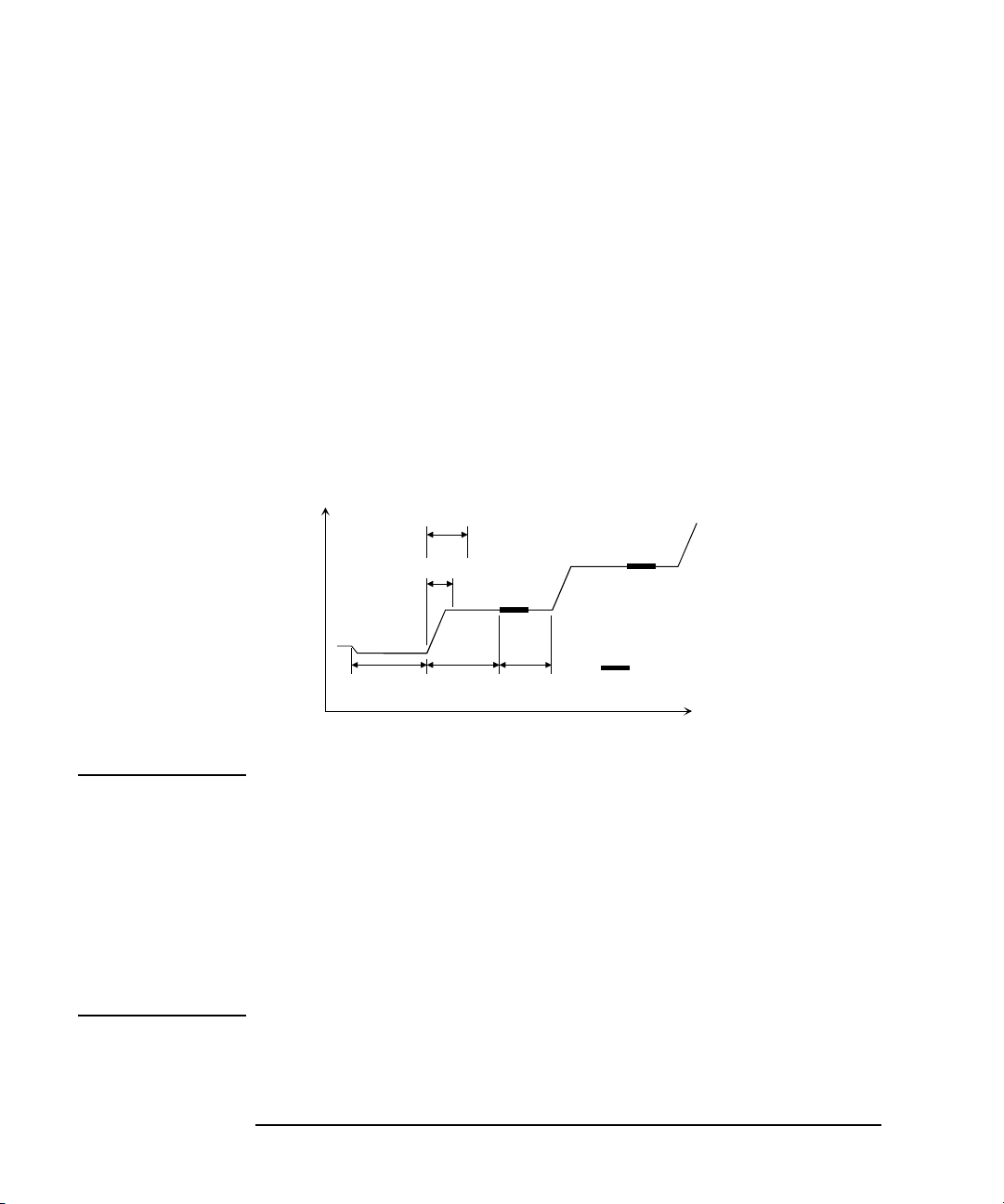
Programming Basics
Measurement wait time
Time
: Measurement
Hold time
Delay time
Source wait time
Step delay time
Programming Tips
To Optimize the Source/Measurement Wait Time
If measurement speed is given top priority or is more important than reliability, set
the wait time shorter by using the WAT command. The source wait time is the time
the source channel always waits before changing the source output value. The
measurement wait time is the time the measurement channel always waits before
starting measurement. The time is given by the following formula:
wait time = initial wait time × A+B
where, initial wait time is the time the B1500 automatically sets and you cannot
change. The initial source wait time is not the same as the initial measurement wait
time. A and B are the command parameters of the WAT command.
The wait time settings are effective for all modules.
Figure 1-3 Source/Measurement Wait Time
NOTE The wait time can be ignored if it is shorter than the delay time.
It is not easy to determine the best wait time. If you specify it too short, the
measurement may start before device characteristics stable. If too long, time will be
wasted.
The initial wait time may be too short for measurements of high capacitance or slow
response devices. Then set the wait time longer.
For measurements of low capacitance or fast response devices, if measurement
speed has top priority or is more important than reliability and accuracy, set the wait
time shorter.
1-58 Agilent B1500 Programming Guide, Edition 3
Page 75

Programming Basics
Programming Tips
To Use the Internal Program Memory
If your program repeats the setup and measurement for a number of devices, use the
internal program memory. For these measurements, using the internal program
memory reduces the command transfer time, and improves the program execution
speed.
You can enter a maximum of 2,000 programs (total 40,000 commands) into the
internal program memory. See Chapter 2, “Remote Mode Functions.”
To Get Time Data with the Best Resolution
To read the time data with the best resolu tion (100 μs), the timer must be cleared
within the following interval:
• 100 sec or less (for FMT1, 2, or 5 data output format)
• 1000 sec or less (for FMT 11, 12, 15, 21, 22, or 25 data output format)
Send the TSR command to clear the timer.
To Use Sweep Source as a Constant Source
The following setup enables sweep source to force a constant current or voltage.
• Sweep start value = Sweep stop value (for WI, WV, or WNX).
Also, setting number of sweep steps to 1 enables to perform a spot measurement.
To Start Measurements Simultaneously
Spot measurement, staircase sweep measurement, and multi channel sweep
measurement enable to use multiple measurement channels. Then the measurement
channels perform measurement in the order defined in the MM command. However ,
the measurement channels with the following setup start measurements
simultaneously.
• To set the multi channel sweep m easu remen t mode (MM 16).
• To set the measurement ranging mode to fixed (for RI or RV).
• To use the high-speed ADC (use AV).
NOTE Measurement setup is independent from source output setup. So, this simultaneous
measurement cannot be brok en by the source o utput setup. A ny set ting of t he outp ut
ranging mode is effective for the simultaneous measurement.
Agilent B1500 Programming Guide, Edition 3 1-59
Page 76

Programming Basics
Voltage or current
Measurement trigger (e.g. XE)
Hold
Start value, Stop value
Previous value
: Measurement
Delay Step delay
Sampling interval = Delay + Step delay
Programming Tips
To Perform Quasi-Sampling Measurement
The following setup enables to perform a quasi-sampling measurement. Then the
sampling interval will be sum of delay time and step delay time.
• Sets the sweep measurement mode (MM 2 or MM 16).
• Sweep start value = Sweep stop value (for WI, WV, or WNX).
• Sets hold time, delay time, and step delay time (WT).
To Interrupt Command Execution
The B1500 executes commands in the received order. However, only the following
commands can interrupt the command execution.
Table 1-12 Interrupt Commands
Command Description
AV Changes the number of averaging samples during the
measurement.
AIT Changes the A/D converter setting of the SMU during the
measurement.
ACT Changes the A/D converter setting of the MFCMU during the
measurement.
AB Aborts the command execution.
*RST Resets the B1500 during the command execution.
XE If the B1500 has been set to the wait status by the PA or PAX
command, the XE command can be used to release the wait
status. For details, see Chapter 4, “Command Reference.”
1-60 Agilent B1500 Programming Guide, Edition 3
Page 77

Programming Basics
Programming Tips
To Use Programs for Agilent 4142B
Agilent B1500 s upports m ost of t he commands and the d ata out put for mat support ed
by the Agilent 4142B Modular DC Source/Monitor. To reuse the programs created
for the Agilent 4142B, confirm the following and modify the programs if necessary.
• To remove all unsupported commands
Some commands are not supported owing to differences in the modules
supported by each instrument. See Table 1-13 that shows the commands not
supported by the B1500. Do not use these commands.
Perform the linear search or binary search measurement as a substitute for the
analog search measurement that needs the analog feedback unit (AFU).
Use a source/monitor unit (SMU) instead of the voltage source/voltage monitor
unit (VS/VMU). Note that the SMU cannot perform the differential voltage
measurements.
• FL command
The initial setting of the FL command is different. It is ON for the Agilent
4142B, and OFF for the B1500.
Add the FL1 command to use the filter.
• AV command
This command is used to set the A/D converter of the B1500.
To set the high resolution ADC installed in the B1500, use the AAD and AIT
commands.
• *TST? command
Use 11 to specify the B1500 mainframe instead of 9 that indicates the 4142B
mainframe.
Table 1-13 Modules and Comman ds Unsupported
Plug-in Module Commands
Analog Feedback Unit ASM, AT, ASV, AIV, AVI
High Current Unit PDM, PDI, PDV
High Voltage Unit POL
Voltage Source/Voltage Monitor Unit VM
Agilent B1500 Programming Guide, Edition 3 1-61
Page 78

Programming Basics
Programming Tips
To Use Programs for Agilent 4155/4156
Agilent B1500 supports commands similar to the FLEX command of the Agilent
4155B/4156B/4155C/4156C Parameter Analyzer. However, not all command sets
are fully compatible. To reuse the programs created for the Agilent 4155/4156, the
following modifications are required.
• To remove all unsupported commands
Table 1-14 shows the commands not supported by the B1500. You cannot use
these commands. The SCPI commands and 4145 syntax commands are not
supported neither.
The B1500 does not need the US and :PAGE commands that are necessary to
change the control mode of the Agilent 4155/4156.
• To check and correct the command syntax
Even if the command name is the same, the available parameters and values may
be different. Check and correct the command parameters.
• To change the FMT command parameter
Use the FMT 21, FMT 22, or F MT 25 command that sets the data output format
compatible with the 4155/4156 ASCII format.
• To delete RMD?
The B1500 does not need the RMD? command that is necessary to put the
measurement data into the output data buffer of the Agilent 4155/4156.
• FL command
The initial setting of the FL command is different. It is ON for the Agilent
4155/4156, and OFF for the B1500.
Add the FL1 command to use the filter.
• AV command
This command is used to set the A/D converter of the B1500.
To set the high resolution ADC installed in the B1500, use the AAD and AIT
commands.
• To replace TI?/TV?/TTI?/TTV? with TI/TV/TTI/TTV respectively
• To replace WM with LSM for the linear search measurement
• To replace TSQ? with TSQ
1-62 Agilent B1500 Programming Guide, Edition 3
Page 79

• If you reuse the built-in IBASIC programs:
• Change the GPIB address.
• Remove the statements to use the built-in flexible disk drive.
Table 1-14 4155/4156 FLEX Commands Unsupported
Category Command
Control mode :PAGE, US, US42
Measurement mode VM, VMD
Staircase/pulsed sweep source setup ESC
Sampling source setup MP
Quasi-static CV measurement setup QSZ?
PGU control POR, SPG, SPP, SRP
Stress source setup STC, STI, STM, STP, STT, STV
Integration time SIT, SLI
Programming Basics
Programming Tips
Measurement execution TI?, TTI?, TTV?, TV?
Time stamp TS Q?
Output data RMD?
Abort/pause/wait *WAI
Zero offset cancel GOC, SOC
SMU/PGU selector SSP
R-box RBC
External trigger STG
Network operation CLOSE, OPEN, PRN, RD?, SDSK, SPL,
SPR, WR
Status byte *CLS, *ESE(?), *ESR?
Query CMD?, *OPT?, :SYST:ERR?
Agilent B1500 Programming Guide, Edition 3 1-63
Page 80

Programming Basics
Programming Tips
To Use Programs for Agilent E5260/E5270
Agilent B1500 s upports m ost of t he commands and the d ata out put for mat support ed
by the Agilent E5260/E5270 Series of Parametric Measurement Solutions. To reuse
the programs created for the Agilent E5 260/E5270, confirm the following and
modify the programs if necessary.
• To remove all unsupported commands
Some commands are not supported owing to differences in the mainframe. See
Table 1-15 that shows the commands not supported by the B1500. The
commands will not cause errors because the B1500 will ignore these commands.
However remove these commands to reduce the load.
• *CAL?, RCV, *TST? command
Use 11 to specify the B1500 mainframe instead of 9 that indicates the
E5260/E5270 mainframe.
• DIAG? command
The B1500 does not support the front panel key test and the beeper test. So, do
not use the parameter item=2 and 5.
Table 1-15 E5260/E5270 FLEX Commands Unsupported
Category Command
Display Control RED, DFM, SPA, MPA, SCH, MCH
Keyboard Control KLC
1-64 Agilent B1500 Programming Guide, Edition 3
Page 81

2 Remote Mode Functions
Page 82

Remote Mode Functions
This chapter describes the functions of the Agilent B1500 in the remote mode, and
the initial settings.
• “Measurement Modes”
• “Synchronous Output”
• “Automatic Abort Function”
• “Parallel Measurement Function”
• “Program Memory”
• “Digital I/O Port”
• “Trig ger Fu nct i on”
• “Initial Settings”
NOTE Synchronous Output
You can use synchronous output that will be synchronized to the output of the
primary sweep or search source. The output is available for the following
measurement modes:
• “Staircase Sweep Measurements”
• “Pulsed Sweep Measurements”
• “Staircase Sweep with Pulsed Bias Measurements”
• “Binary Search Measurements”
• “Linear Search Measurements”
The synchronous source supports the output mode (voltage or current) same as the
primary source, and does not support the pulsed output.
2-2 Agilent B1500 Programming Guide, Edition 3
Page 83

Remote Mode Functions
Measurement Modes
Measurement Modes
The Agilent B1500 provides the following measurement modes.
• “Spot Measurements”
• “Pulsed Spot Measurements”
• “Staircase Sweep Measurements”
• “Multi Channel Sweep Measurements”
• “Pulsed Sweep Measurements”
• “Staircase Sweep with Pulsed Bias Measurements”
• “Quasi-Pulsed Spot Measurements”
• “Binary Search Measurements”
• “Linear Search Measurements”
• “Sampling Measurement”
• “Quasi-static CV Measurement”
• “Spot C Measurement”
• “Pulsed Spot C Measurement”
• “CV (DC bias) Sweep Measurement”
• “Pulsed Sweep CV Measurement”
• “C-f Sweep Measurement”
• “CV (AC level) Sweep Measurement”
• “C-t Sampling Measurement”
NOTE About Search Measurements
The B1500 supports search measurement to find a point on an I-V curve where a
specified condition is satisfied. For example, it searches for a breakdown voltage or
threshold voltage at a specified current.
Search measurements are performed by one or two SMUs. For two SMUs, one is the
search channel, and the other is a sense channel. When one SMU is used, it serves as
both search and sense channel. Basically, the search channel forces voltage or
current until the search stop condition is satisfied.
Agilent B1500 Programming Guide, Edition 3 2-3
Page 84

Remote Mode Functions
Voltage or cu rrent
DV/DI DV/DI Measurement trigger (e.g. XE)
Measurement time
Channel 1 output
Channel 2 output
Setup value
Previous value
Setup value
Previous value
Voltage or cu rrent
Time
: Measurement
Measurement Modes
Spot Measurements
Spot measurement is performed as shown below. The measurement channel
performs one point measurement.
Figure 2-1 Spot Measurements
1. The source channel starts output by the DV or DI command. Multiple channels
can be set.
2. The measurement channel starts measurement by a trigger, such as the XE
command. If the trigger is received during the settling time of the source
channels, measurement starts after the settling time.
If you use multiple measurement channels, the channels perform measurement
in the order defined in the MM command.
3. After measurement, the source channels continue the source output.
For 0 V output, enter the DZ command that is used to memorize the present
settings of the channel and change the output to 0 V.
NOTE The DV command is used to force voltage, and the DI command is used to force
current.
2-4 Agilent B1500 Programming Guide, Edition 3
Page 85

Pulsed Spot Measurements
Voltage or current
Pulse value
Base value
Previous value
Time
: Measurement
Hold time
Pulse width
Pulse period
Hold time
TriggerTrigger (e.g. XE)
Pulse period
PT/PV/PI
Pulsed spot measurement is performed as shown below. The measurement channel
performs one point measurement while the source channel is forcing a pulse.
Figure 2-2 Pulsed Spot Measurements
Remote Mode Functions
Measurement Modes
1. The pulse source channel sets output by the PT command and the PV or PI
command. Only one channel can be used for the pulse source.
2. The pulse source channel starts output by a trigger, such as the XE command.
3. The measurement channel starts measurement as shown i n Figure 2-2.
The channel performs measurement so that the pulse width and pulse period are
kept (the integration time setting is ignored). Only one channel can be used for
measurement.
4. After measurement, the pulse source forces the pulse base value, and keeps it.
If the next trigger occurs within the pulse period, pulse output is as follows.
• If the rest of the pulse period is longer than the hold time as shown in Figure
2-2, the pulse source waits for the rest, then starts the pulse output.
• If the rest of the pulse period is shorter than the hold time, the pulse source
waits for the hold time since the last trigger, then starts the pulse output.
For 0 V output, enter the DZ command that is used to memorize the present
settings of the channel and change the output to 0 V.
NOTE The PT command sets the pulse timing parameters, such as pulse width and pulse
period. The PV command sets voltage pulse, and the PI command sets current pu lse.
Agilent B1500 Programming Guide, Edition 3 2-5
Page 86

Remote Mode Functions
Voltage or current
Stop value
Start value
Previous value
Time
: Measurement
Hold time
Step delay time
Trigger (e.g. XE)
WT/WM/WV/WI
Delay time
Step delay time
Delay time
Measurement Modes
Staircase Sweep Measurements
Staircase sweep measurement is performed as shown below. The source channel
forces staircase sweep voltage or current, and the measurement channel performs
one point measurement at each sweep step.
Figure 2-3 Staircase Sweep Measurements
1. The staircase sweep source sets output by the WT, WM, and WV or WI
commands. Only one channel can be used for the sweep source.
2. The sweep source starts output by a trigger, such as the XE command.
3. After the hold time, the sweep source waits for the delay time.
4. After the delay time, the measurement channel starts measurement.
If you use multiple measurement channels, the channels perform measurement
in the order defined in the MM command.
5. After measurement, the sweep source waits for the rest of the step delay time if
it is set, and the sweep source changes the output value.
6. The B1500 repeats 4 and 5 for all sweep steps.
7. After the sweep measurement, the sweep source forces the start or stop value, as
specified by the WM command, and keeps it.
For 0 V output, enter the DZ command that is used to memorize the present
settings of the channel and change the output to 0 V.
2-6 Agilent B1500 Programming Guide, Edition 3
Page 87

Remote Mode Functions
Voltage or cu rrent
Start value
Time
Stop value
Primary sweep
Synchronous sweep
Previous value
Trigger (e.g. XE)
WT/WM/WV/WI
WSV/WSI
Voltage or cu rrent
Start value
Stop value
Previous value
Measurement Modes
NOTE The WT command sets the hold time, delay time, and step delay time. The WM
command sets the automatic abort function and the output after measurement. The
WV command sets the sweep voltage, and the WI command sets the sweep current.
The start and stop values must have the same polarity for log sweep.
To Use
Synchronous
Sweep Source
One more channel can be set up as a sweep source that has the output synchronized
with the staircase sweep. Refer to “Synchronous Output” on page 2-39. After the
measurement, the synchronous sweep source forces the start or stop value, as
specified by the WM command, and keeps it.
Figure 2-4 Synchronous Sweep
NOTE The WSV command sets the sweep voltage, and the WSI command sets the sweep
current. You can use the same output mode (voltage or current) as the primary
sweep. The start and stop values must have the same polarity for log sweep.
To Stop Sweep
Output
An automatic abort function is available. Refer to “Automatic Abort Function” on
page 2-41.
Even if the automatic abort function is disabled, the B1500 automatically stops
measurement if power compliance is enabled for the sweep source and the power
compliance or an automatic abort condition is detected.
Agilent B1500 Programming Guide, Edition 3 2-7
Page 88

Remote Mode Functions
Trigger (e.g. XE)
WT/WM/WV/WI
Voltage or current
Stop value
Start value
Previous value
Time
: Measurement
Hold time
Delay time
Stop value
Start value
Previous value
Voltage or current
Stop value
Start value
Previous value
Voltage or current
WNX
WNX
Primary sweep source
Second sweep source
Tenth sweep source
Step delay time
Step delay time
Delay time
Measurement Modes
Multi Channel Sweep Measurements
Multi channel sweep measurement is performed as shown below. The source
channel forces staircase sweep voltage or current, and the measurement channel
performs one point measuremen t at each sweep step . Up to ten ch annels can be used
for both sweep output and measurement. Both voltage output mode and current
output mode are available for the sweep s ources regardless o f the output mode of the
primary sweep source.
Figure 2-5 Multi Channel Sweep Measurements using High-Resolution A/D Converter
1. The primary sweep source sets output by the WV or WI comman ds. And the nth
(n=2 to 10) sweep source sets output by the WNX command.
2. The sweep sources simultaneously start output by a trigger, such as the XE
command. However, if a sweep source sets power compliance or forces
logarithmic sweep current, the sweep sources start output in the order specified
by the n value. Then the first output is forced by the channel set by the WI or
WV command.
3. After the hold time, the sweep sources wait for the delay time.
4. After the delay time, the measurement channel starts measurement. If you use
multiple measurement channels, the channels that use the high speed ADC with
the fixed ranging mode start measurement simultaneously, then other channels
perform measurement in the order defined in the MM command.
5. After measurement, the sweep source waits for the rest of the step delay time if
it is set, and the sweep source changes the output value.
2-8 Agilent B1500 Programming Guide, Edition 3
Page 89

Remote Mode Functions
Measurement Modes
6. The B1500 repeats 4 and 5 for all sweep steps.
7. After the sweep measurement, the sweep sources force the start or stop value, as
specified by the WM command, and keep it.
For 0 V output, enter the DZ command that is used to memorize the present
settings of the channel and change the output to 0 V.
NOTE The WT command sets the hold time, delay time, and step delay time. The WM
command sets the automatic abort function and the output after measurement. The
WV/WI command sets the output of the f irst sweep sou rce, and the WNX command
sets the output of the nth (n=2 to 10) sweep source. The start and stop values must
have the same polarity for log sweep.
To Stop Sweep
Output
An automatic abort function is available. Refer to “Automatic Abort Function” on
page 2-41.
Even if the automatic abort function is disabled, the B1500 automatically stops
measurement if power compliance is enabled for the sweep source and the power
compliance or an automatic abort condition is detected.
Agilent B1500 Programming Guide, Edition 3 2-9
Page 90

Remote Mode Functions
Voltage or current
Stop value
Start value
Previous value
Time
: Measurement
Hold time
Pulse period
Trigger (e.g. XE)
PT/WM/PWV/PWI
Pulse base value
Pulse width
Pulse period Pulse period
Measurement Modes
Pulsed Sweep Measurements
Pulsed sweep measurement is performed as shown below . The s ource channel forces
pulsed sweep voltage or current, and the measurement channel performs one point
measurement at each sweep step.
Figure 2-6 Pulsed Sweep Measurements
1. The pulsed sweep source sets output by the PT, WM, and PWV or PWI
commands. Only one channel can be used for the pulsed sweep source.
2. The pulsed sweep source starts output by a trigger, such as the XE command.
3. After the hold time, the measurement channel starts measurement as shown in
Figure 2-6. The channel performs measur ement so that the puls e width and pulse
period are kept (the integration time set ting is ignored) . Only one channel can be
used for measurement.
4. After measurement, the pulsed sweep source forces the pulse base value, and
waits for the rest of the pulse period. Then the pulsed sweep source changes the
output value.
5. The B1500 repeats measurement and 4 for all sweep steps.
6. After the pulsed sweep measurement, the pulsed sweep source forces the pulse
base value, and keeps it.
For 0 V output, enter the DZ command that is used to memorize the present
settings of the channel and change the output to 0 V.
2-10 Agilent B1500 Programming Guide, Edition 3
Page 91

Remote Mode Functions
Voltage or current
Start value
Time
Stop value
Pulse base value
Stop value
Synchronous sweep
Pulsed sweep
Previous value
Trigger (e.g. XE)
PT/WM/PWV/PWI
WSV/WSI
Start value
Previous value
Voltage or current
Measurement Modes
NOTE The PT command sets the hold time, pulse width, and pulse period. The WM
command sets the automatic abort function. The PWV sets the pulsed sweep
voltage, and the PWI sets the pulsed sweep current.
To Use
Synchronous
Sweep Source
One more channel can be set up as a staircase sweep source that has the output
synchronized with the pulsed sweep. Refer to “Syn chronou s Outpu t” on page 2-39.
After the measurement, the synchronous sweep source forces the start value, and
keeps it.
Figure 2-7 Synchronous Sweep
NOTE The WSV command sets the sweep voltage, and the WSI command sets the sweep
current. You can use the same output mode (voltage or current) as the pulsed sweep.
To Stop Sweep
Output
An automatic abort function is available. Refer to “Automatic Abort Function” on
page 2-41.
Even if the automatic abort function is disabled, the B1500 automatically stops
measurement if power compliance is enabled for the sweep source and the power
compliance or an automatic abort condition is detected.
Agilent B1500 Programming Guide, Edition 3 2-11
Page 92

Remote Mode Functions
Voltage or current
Start value
Time
Stop value
Pulse base value
Pulse peak value
Pulsed bias
Staircase sweep
Previous value
Trigger (e.g. XE)
WM/WV/WI
PT/PV/PI
Previous value
Voltage or current
: Measurement
Hold time
Pulse width
Pulse period
Measurement Modes
Staircase Sweep with Pulsed Bias Measurements
Staircase sweep with pulsed bias measurement is performed as shown below. The
source channel forces staircase sweep voltage or current, the pulse channel forces
pulsed bias, and the measurement channel performs one point measurement at each
sweep step.
Figure 2-8 Staircase Sweep with Pulsed Bias Measurements
1. The staircase sweep source sets output by the WM, and WV or WI commands.
Only one channel can be used for the sweep source.
2. The pulsed source sets output by the PT, and PV or PI commands. Only one
channel can be used for the pulsed source.
3. The source channels start output by a trigger, such as the XE command.
4. After the hold time, the measurement channel starts measurement as shown in
Figure 2-8. The channel performs measur ement so that the puls e width and pulse
period are kept (the integration time set ting is ignored) . Only one channel can be
used for measurement.
5. After the measurement, the sweep source changes the output value. Then the
pulsed source forces the pulse base value, and waits for the rest of the pulse
period until the next pulse output.
6. The B1500 repeats measurement and 5 for all sweep steps.
2-12 Agilent B1500 Programming Guide, Edition 3
Page 93

Remote Mode Functions
Voltage or cu rrent
Start value
Time
Stop value
Primary sweep
Synchronous sweep
Previous value
Trigger (e.g. XE)
WT/WM/WV/WI
WSV/WSI
Voltage or cu rrent
Start value
Stop value
Previous value
Measurement Modes
7. After the sweep measurement, the pulsed source forces the pulse base value, and
the sweep source forces the start or stop value, as specified by the WM
command, and keeps it.
For 0 V output, enter the DZ command that is used to memorize the present
settings of the channel and change the output to 0 V.
NOTE The WM command sets the automatic abort function and the output after
measurement. The WV command sets the sweep vo ltage, an d th e WI comm and sets
the sweep current. The start and stop values must have the same polarity for log
sweep.
The PT command sets the pulse timing parameters, such as pulse width and pulse
period. The PV command sets the voltage pulse, and the PI command sets current
pulse.
To Use
Synchronous
One more channel can be set up as a sweep source that has the output synchronized
with the staircase sweep. Refer to “Synchronous Output” on page 2-39.
Sweep Source
After the measurement, the synchronous sweep source forces the start or stop value,
as specified by the WM command, and keeps it.
Figure 2-9 Synchronous Sweep
Agilent B1500 Programming Guide, Edition 3 2-13
Page 94

Remote Mode Functions
Measurement Modes
NOTE The WSV command sets the sweep voltage, and the WSI command sets the sweep
current. You can use the same output mode (voltage or current) as the primary
sweep. The start and stop values must have the same polarity for log sweep.
To Stop Sweep
Output
An automatic abort function is available. Refer to “Automatic Abort Function” on
page 2-41.
Even if the automatic abort function is disabled, the B1500 automatically stops
measurement if power compliance is enabled for the sweep source and the power
compliance or an automatic abort condition is detected.
2-14 Agilent B1500 Programming Guide, Edition 3
Page 95
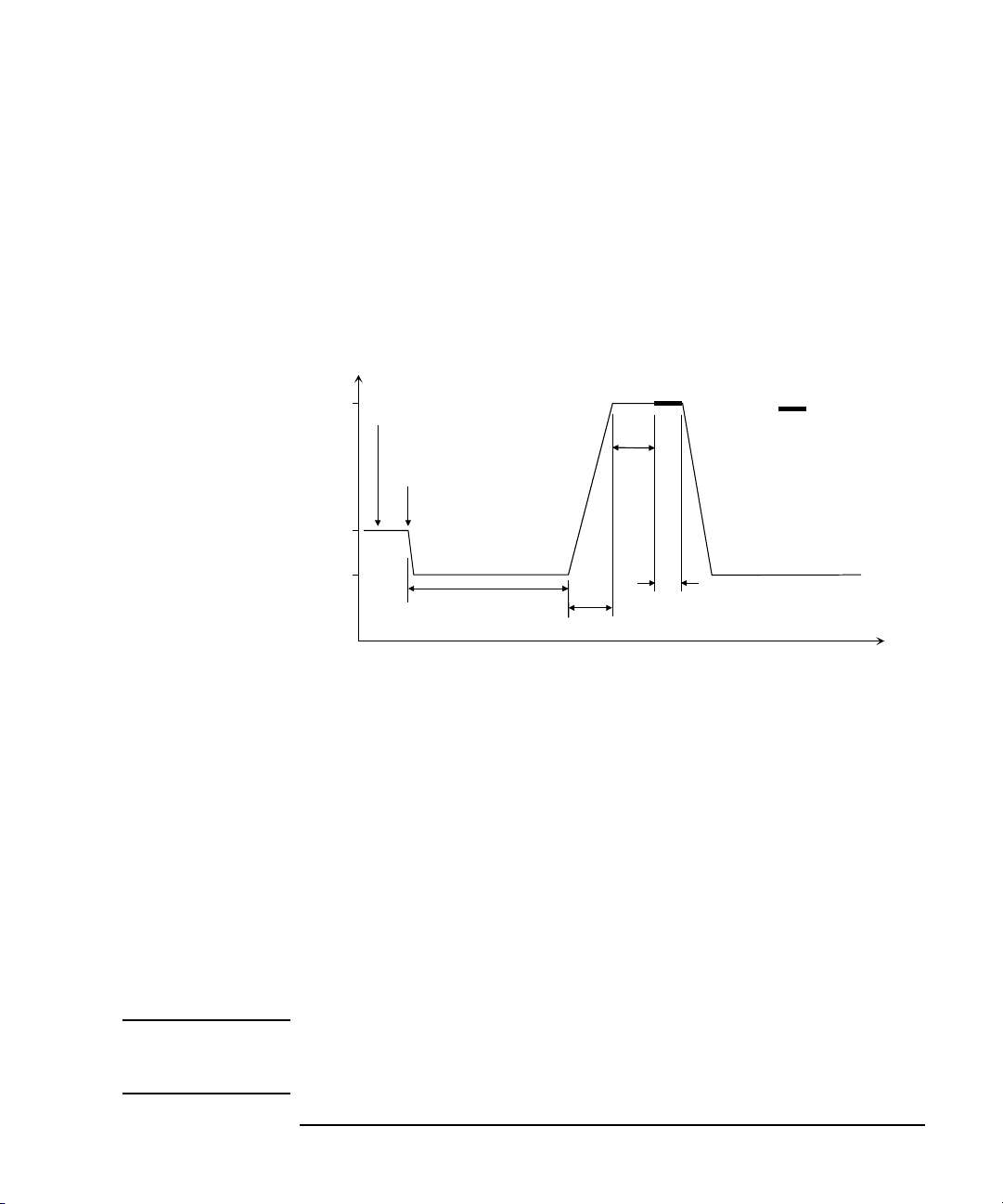
Quasi-Pulsed Spot Measurements
Voltage
Measurement time
X value
Start value
Previous value
Time
: Measurement
Hold time
Delay
time
Trigger (e.g. XE)
BDT/BDM/BDV
Settling detectio n time
The X value is the voltage whe n the settling detection is stopped.
Quasi-pulsed spot measurement is performed as shown below. The measurement
channel performs one point measurement while the source channel forces a
quasi-pulse voltage. This measurement mode can minimize the output time of the
measurement voltage. So it is effective for the breakdown voltage meas urement and
the reliability test.
Figure 2-10 Quasi-Pulsed Spot Measurements
Remote Mode Functions
Measurement Modes
1. The quasi-pulse source channel sets output by the BDT, BDM, and BDV
commands. Only one channel can be used for the quasi-pulse source.
2. The quasi-pulse source starts output by a trigger, such as the XE command.
3. After the hold time, the quasi-pulse source starts the voltage transition to the
stop value (settling detection time). Also, it performs voltage measurement
(settling detection) in the interval set by the BDM command. The voltage
transition and settling detection continue until the output voltage slew rate
becomes half of the rate when settling detection started. The slew rate depends
on the cabling and the characteristics of the device. You cannot define it directly .
In normal operation, the slew rate will be slower in the following conditions:
• When the quasi-pulse source applies voltage close to the stop value.
• When the quasi-pulse source reaches its current compliance due to the
breakdown condition of the device under test.
NOTE If the slew rate was too slow when settling detection started or if the settling
detection time was too long, an error occurs and the source returns its output to the
start value immediately. See “BDM” on page 4-35.
Agilent B1500 Programming Guide, Edition 3 2-15
Page 96

Remote Mode Functions
Measurement Modes
4. After the settling detection stops, the quasi-pulse source keeps the output.
5. After the delay time, the measurement channel starts measurement.
Only one channel can be used for measurement.
6. After measurement, the quasi-pulse source immed iately returns the output to the
start value and keeps it.
For 0 V output, enter the DZ command that is used to memorize the present
settings of the channel and change the output to 0 V.
NOTE If there is noise or skew on the output voltage, settling detection might stop at an
unexpected voltage.
NOTE The BDT command sets the hold time and delay time, and the BDM command sets
the settling detection interval and measurement mode (voltage or current); the BDV
command sets the output. Also |start-stop| must be 10 V or more.
2-16 Agilent B1500 Programming Guide, Edition 3
Page 97

Binary Search Measurements
Start
Stop
D = | Stop - Start |
+D/4
-D/2
-D/8
-D/16
(1) Normal output
Search stopped
+D/32
+D/64
: Measurement
Start
Stop
+D/4
+D/2
-D/8
-D/16
(2) Cautious output
Search stopped
+D/32
+D/64
Time
Voltage or cu rrent
Hold time
Delay time
Hold time
Delay time
Delay time
Delay time
Trigger
Trigger
BSM, BST, and
BSV or BSI
BSM, BST, and
BSV or BSI
Binary search measurement is performed as shown below. The source channel
forces voltage or current, and the measurement channel performs one point
measurement. The B1500 repeats this until the search s top condition is satisfied, an d
returns the source’s last output value. The last measurement data is also returned if it
is set by the BSVM command.
Figure 2-11 Binary Search Measurements
Remote Mode Functions
Measurement Modes
1. The search source sets output by the BSM, BST, and BSV or BSI commands.
Only one channel can be used for the search source.
2. The search source starts output by a trigger, such as the XE command.
3. After the hold time, the measurement channel waits for the delay time, and starts
measurement as shown in Figure 2-11. The measurement channel can be set by
the BGI or BGV command. Only one channel can be used for measurement.
4. After measurement, the search source changes the output value. The output
value depends on the ou tput contro l mode, normal or cauti ous, selected by the
BSM command. See Figure 2-11.
Agilent B1500 Programming Guide, Edition 3 2-17
Page 98

Remote Mode Functions
Voltage or current
Start value
Time
Stop value
Primary searc h so ur c e
Synchronous search so urce
Previous value
Trigger (e.g. XE)
BSM, BST, and BSV/BSSV or BSI/BSSI
Offset
Offset
Offset
Measurement Modes
5. The B1500 repeats measurement and 4 until the search stop condition is
satisfied. The search stop condition is one of the following conditions selected
by the BGI or BGV command .
• Measured value = Search target value ± limit
• Number of measurement points > limit
6. After the search measurement, the search source forces the start value, the stop
value, or the last output value, as specified by the BSM command, and keeps it.
For 0 V output, enter the DZ command that is used to memorize the present
settings of the channel and change the output to 0 V.
NOTE The BSM command sets the search control mode, the automatic abort function, and
the output after search. The BST command sets the hold time and delay time. The
BSV/BSI command sets the search output, and the BGI/BGV command sets the
measurement channel.
To Use
Synchronous
Output Channel
Figure 2-12 Synchronous Output
NOTE The BSSV/BSSI command sets the synchronous output. You can use the same
You can use the synchronous output channel that provides the output synchronized
with the search source. Refer to “Synchronous Output” on page 2-39. After
measurement, the synchronous channel forces the start+offset, stop+offset, or the
last output value, as specified by the BSM command, and keeps it.
output mode (voltage or current) as the search source. All output values must be
covered by the output range of the search source.
2-18 Agilent B1500 Programming Guide, Edition 3
Page 99

Linear Search Measurements
Voltage or cu rrent
Start value
Time
Stop value
Previous value
Trigger (e.g. XE)
LSM, LSTM, and LSV or LSI
: Measurement
Hold time
Delay time
Search stopped
Delay time
Linear search measurement is performed as shown below. The source channel
sweeps voltage or current, and the measurement channel performs one point
measurement at each sweep step. The B1500 stops sweep and measurement when
the search stop condition is satisfied, and returns the source’s last output value. The
last measurement data is also returned if it is set by the LSVM command.
Figure 2-13 Linear Search Measurements
Remote Mode Functions
Measurement Modes
1. The search source sets output by the LSM, LSTM, and LSV or LSI commands.
Only one channel can be used for the search source.
2. The search source starts output by a trigger, such as the XE command.
3. After the hold time, the measurement channel waits for the delay time, and starts
measurement as shown in Figure 2-13. The measurement channel can be set by
the LGI or LGV command. Only one channel can be used for the measurement.
4. After measurement, the search source changes the output value.
5. The B1500 repeats measurement and 4 until the search stop condition is
satisfied. The search stop condition is one of the following conditions selected
by the LGV or LGI command.
• Measured value is over the search target value.
• Measured value breaks the search target value.
6. After the search measurement, the search source forces the start value, the stop
value, or the last output value, as specified by the LSM command, and keeps it.
For 0 V output, enter the DZ command that is used to memorize the present
settings of the channel and change the output to 0 V.
Agilent B1500 Programming Guide, Edition 3 2-19
Page 100

Remote Mode Functions
Voltage or current
Start value
Time
Stop value
Primary search source
Synchronous search source
Previous value
Trigger (e.g. XE)
LSM, LSTM, and LSV/LSSV or LSI/LSSI
Offset
Offset
Offset
Measurement Modes
NOTE The LSM command sets the automatic abort function and the output after search.
The LSTM command sets the hold time and delay time. The LSV/LSI command
sets the search output, and the LGI/LGV command sets the measurement channel.
To Use
Synchronous
You can use the synchronous output ch annel th at pro vides outp ut synch ronized w ith
the search source. Refer to “Synchronous Output” on page 2-39.
Output Channel
After measurement, the synchronous channel forces the start+offset, stop+offset, or
the last output value, as specified by the LSM command, and keeps it.
Figure 2-14 Synchronous Output
NOTE The LSSV/LSSI command sets the synchronous output. You can use the same
output mode (voltage or current) as the search source. All output values must be
covered by the output range of the search source.
2-20 Agilent B1500 Programming Guide, Edition 3
 Loading...