

Page 1

User’s Reference
Publication number 01660-97034
Second edition, January 2000
For Safety information, Warranties, and Regulatory
information, see the pages behind the index
Copyright Agilent Technologies 1991 - 2000
All Rights Reserved
Agilent Technologies 1660A
Series 50/100-MHz State,
500-MHz Timing Logic
Analyzers
Page 2
1
Introduction
In This Book
The User’s Reference manual
contains field and feature definitions
which explain the details of the
instrument operation. Use this part
of the manual set for information on
what the menu fields do and what
they are used for. This manual
covers all 1660A Series analyzers.
The User’s Reference is divided into
two parts. The first part covers
general product information such as,
probing, using the front panel
interface, using the keyboard and
mouse, connecting a printer, disk
drive operation, the RS-232/GPIB/
Centronix interface, and the utilities
menu. The second part covers the
state and timing analyzers. It
explains the analyzer menus and
what they are used for. There are
separately tabbed chapters for each
analyzer menu, a chapter for error
messages, and a chapter for
instrument specifications. The
common menu fields which are found
in the majority of menus have been
placed in a separate chapter. You will
be referenced back to the "Common
Menu Fields" chapter when these
fields are encountered.
2
3
4
5
6
7
8
9
10
11
12
13
14
15
Probing
Using the Front Panel Interface
Using the Optional
Keyboard and Mouse
Connecting a Printer
Disk Drive Operations
The RS-232/GPIB Interface
The Utilities Menu
The Common Menu Fields
The Configuration Menu
The Format Menu
The Trigger Menu
The Listing Menu
The Waveform Menu
The Mixed Display Menu
iii
Page 3

Analyzer type considerations
In the Configuration menu you have the choice of configuring an
analyzer machine as either a State analyzer or a Timing analyzer.
Some menus in the analyzer will change depending on the analyzer
type you choose. For example, since a Timing analyzer does not use
external clocks, the clock assignment fields in the Format menu will
not be available.
If a menu field is only available to a particular analyzer type, the field
is designated (Timing only) or (State only) after the field name. If no
designation is shown, the field is available for both types.
iv
Page 4
16
The Chart Menu
17
18
19
20
The Compare Menu
Error Messages
Specifications and
Characteristics
Operator’s Service
Index
v
Page 5
vi
Page 6

Contents
1 Introduction
User Interface 1–4
Configuration Capabilities 1–5
Key Features 1–7
Accessories Supplied 1–8
Accessories Available 1–9
2 Probing
General-Purpose Probing System Description 2–5
Assembling the Probing System 2–8
3 Using the Front-Panel Interface
Front-Panel Controls 3–3
Rear-Panel Controls and Connectors 3–8
How to Power-up The Analyzer 3–10
How to Select Menus 3–11
How to Select the System Menus 3–13
How to Select Fields 3–15
How to Configure Options 3–18
How to Enter Numeric Data 3–19
How to Enter Alpha Data 3–21
How to Roll Offscreen Data 3–23
How to Use Assignment/Specification Menus 3–25
4 Using the Mouse and the Optional Keyboard
Moving the Cursor 4–3
Entering Data into a Menu 4–4
Using the Keyboard Overlays 4–5
Defining Units of Measure 4–7
Assigning Edge Triggers 4–8
Closing a Menu 4–8
Contents - 1
Page 7

Contents
5 Connecting a Printer
GPIB Printers 5–3
RS-232C Printers 5–8
Parallel Printers (1664A Only) 5–13
Connecting to Other Hewlett-Packard Printers 5–15
Printing the Display 5–17
6 Disk Drive Operations
How to Access the Disk Menu 6–5
How to Install a Disk 6–6
How to Select a Disk Operation 6–7
How to Load a File 6–8
How to Format a Disk 6–10
How to Store Files on a Disk 6–12
How to Rename a File 6–15
How to Autoload a File 6–17
How to Purge a File 6–19
How to Copy a File 6–20
How to Pack a Disk 6–22
How to Duplicate a Disk 6–23
How to Make a Directory 6–25
7 The RS-232C, GPIB, and Centronix Interface
The GPIB Interface 7–8
The RS-232C Interface 7–10
The Centronix Interface (1664A Only) 7–13
Configuring the Interface for a Controller or a Printer (1660A through 1663A
Only) 7–14
8 The System Utilities
Real Time Clock Adjustments (1660A Through 1663A Only) 8–4
Update FLASH ROM (1660A Through 1663A Only) 8–5
Display Grey Shade Adjustments 8–5
Sound On / Off 8–5
Contents - 2
Page 8

9 The Common Menu Fields
System/Analyzer Field 9–4
Menu Field 9–5
Print Field 9–6
Run/Stop Field 9–9
Base Field 9–10
Label Field 9–11
Label / Base Roll Field 9–13
10 The Configuration Menu
Name Field 10–3
Type Field 10–4
Unassigned Pods List 10–5
Activity Indicators 10–7
System / Analyzer Field 10–8
Menu Field 10–8
Print Field 10–8
Run Field 10–8
Contents
11 The Format Menu
State Acquisition Mode Field (State only) 11–4
Timing Acquisition Mode Field (Timing only) 11–5
Clock Inputs Display 11–13
Pod Field 11–14
Pod Clock Field (State only) 11–15
Pod Threshold Field 11–19
Master and Slave Clock Field (State only) 11–21
Setup/Hold Field (State only) 11–23
Symbols Field 11–25
Label and Pod Rolling Fields 11–29
Label Assignment Fields 11–30
Label Polarity Fields 11–32
Bit Assignment Fields 11–33
System / Analyzer Field 11–35
Menu Field 11–35
Contents - 3
Page 9

Contents
Print Field 11–35
Run Field 11–35
12 The Trigger Menu
Trigger Sequence Levels 12–6
Modify Trigger Field 12–8
Pre-defined Trigger Macros 12–11
Using Macros to Create a Trigger Specification 12–13
Timing Trigger Macro Library 12–14
State Trigger Macro Library 12–16
Modifying the User-level Macro 12–19
Resource Terms 12–26
Assigning Resource Term Names and Values 12–28
Label and Base Fields 12–32
Arming Control Field 12–33
Acquisition Control 12–36
Trigger Position Field 12–37
Sample Period Field 12–38
Branches Taken Stored / Not Stored Field 12–38
Count Field (State only) 12–39
13 The Listing Menu
Markers Field 13–4
Pattern Markers 13–5
Find X-pattern / O-pattern Field 13–6
Pattern Occurrence Fields 13–7
From Trigger / Start / X Marker Field 13–8
Specify Patterns Field 13–9
Contents - 4
Page 10

Stop Measurement Field 13–13
Clear Pattern Field 13–16
Time Markers 13–17
Trig to X / Trig to O Fields 13–18
Statistics Markers 13–19
States Markers (State only) 13–21
Trig to X / Trig to O Fields 13–22
Data Roll Field 13–23
Label and Base Fields 13–24
Label / Base Roll Field 13–24
System / Analyzer Field 13–25
Menu Field 13–25
Print Field 13–25
Run Field 13–25
Contents
14 The Waveform Menu
Acquisition Control Field 14–5
Accumulate Field 14–6
States Per Division Field (State only) 14–7
Seconds Per Division Field (Timing only) 14–8
Delay Field 14–9
Sample Period Display (Timing only) 14–10
Markers Field 14–12
Pattern Markers 14–13
X-pat / O-pat Occurrence Fields 14–14
From Trigger / Start / X Marker Field 14–15
X to O Display Field (Timing only) 14–16
Center Screen Field 14–17
Specify Patterns Field 14–18
Stop Measurement Field 14–22
Clear Pattern Field 14–25
Contents - 5
Page 11

Contents
Time Markers 14–26
Trig to X / Trig to O Fields 14–27
Marker Label / Base and Display 14–28
Statistics Markers 14–29
States Markers (State only) 14–31
Trig to X / Trig to O Fields 14–32
Marker Label / Base and Display 14–33
Waveform Display 14–34
Waveform Label Field 14–36
System / Analyzer Field 14–39
Menu Field 14–39
Print Field 14–39
Run Field 14–39
15 The Mixed Display Menu
Inserting Waveforms 15–3
Interleaving State Listings 15–3
Time-Correlated Displays 15–4
Markers 15–5
16 The Chart Menu
Selecting the Axes for the Chart 16–6
Y-axis Label Value Field 16–7
X-axis Label / State Type Field 16–8
Scaling the Axes 16–9
Min and Max Scaling Fields 16–10
Markers / Range Field 16–11
Contents - 6
Page 12

Pattern Markers 16–12
Find X-pattern / O-pattern Field 16–13
Pattern Occurrence Fields 16–14
From Trigger / Start / X-Marker Fields 16–15
Specify Patterns Field 16–16
Stop Measurement Field 16–19
Clear Pattern Field 16–22
Time Markers 16–23
Trig to X / Trig to O Fields 16–24
Statistics Markers 16–25
States Markers 16–27
Trig to X / Trig to O Fields 16–28
System / Analyzer Field 16–29
Menu Field 16–29
Print Field 16–29
Run Field 16–29
Contents
17 The Compare Menu
Reference Listing Field 17–5
Difference Listing Field 17–6
Copy Listing to Reference Field 17–8
Find Error Field 17–9
Compare Full / Compare Partial Field 17–10
Mask Field 17–11
Specify Stop Measurement Field 17–12
Data Roll Field 17–15
Bit Editing Field 17–16
Label and Base Fields 17–17
Label / Base Roll Field 17–17
System / Analyzer Field 17–18
Menu Field 17–18
Contents - 7
Page 13

Contents
Print Field 17–18
Run Field 17–18
18 Error Messages
Error Messages 18–3
Warning Messages 18–5
Advisory Messages 18–8
19 Specifications and Characteristics
Specifications 19–3
Specifications and Characteristics 19–4
20 Operator’s Service
Preparing For Use 20–3
To inspect the logic analyzer 20–4
Ferrites (1664A Only) 20–4
To apply power 20–6
To operate the user interface 20–6
To set the line voltage 20–7
To degauss the display 20–8
To clean the logic analyzer 20–8
To test the logic analyzer 20–8
Troubleshooting 20–9
To use the flowcharts 20–9
To check the power-up tests 20–12
To run the self-tests (1660A through 1663A) 20–13
To run the self-tests (1664A) 20–19
To test the auxiliary power 20–26
Contents - 8
Page 14

1
Introduction
Page 15

Logic Analyzer Description
The Agilent Technologies 1660A Series Logic Analyzers are part of a
new generation of general-purpose logic analyzers. The 1660A Series
consists of five different models ranging in channel width from 34
channels to 136 channels. State speed is either 50-MHz or 100-MHz
(depending on the model), and all models have 500-MHz timing
speeds. The 1660A series logic analyzers are designed as full-featured
stand-alone instruments for use by digital and microprocessor
hardware and software designers. All models have GPIB, RS-232C,
and/or Centronix interfaces for hard copy printouts and control by a
host computer.
• The 1660A has 100-MHz state speed, 130 data channels, six
data/clock channels, and both GPIB/RS-232C interfaces.
• The 1661A has 100-MHz state speed, 96 data channels, six
data/clock channels, and both GPIB/RS-232C interfaces.
• The 1662A has 100-MHz state speed, 64 data channels and four
data/clock channels, and both GPIB/RS-232C interfaces.
• The 1663A has 100-MHz state speed, 32 data channels, two
data/clock channels, and both GPIB/RS-232C interfaces.
• The 1664A has 50-MHz state speed, 32 data channels, two
data/clock channels, and a Centronix interface (GPIB/RS-232C
available as options).
Memory depth is 4 Kbytes per channel in all pod pair groupings, or
8 Kbytes per channel on one pod of a pod pair (half channel mode).
Measurement data is displayed as data listings and waveforms, and
can also be plotted on a chart or compared to a reference image.
The 50/100-MHz state analyzer has master, master/slave, and
demultiplexed clocking modes available. Measurement data can be
stamped with state or time tags. For triggering and data storage, the
state analyzer uses 12 sequence levels with two-way branching, 10
pattern resource terms, 2 range terms, and 2 timers.
1–2
Page 16

Introduction
The 500-MHz timing analyzer has conventional, transitional, and glitch
timing modes with variable width, depth, and speed selections.
Sequential triggering uses 10 sequence levels with two-way branching,
10 pattern resource terms, 2 range terms, 2 edge terms and 2 timers.
1–3
Page 17
Introduction
User Interface
User Interface
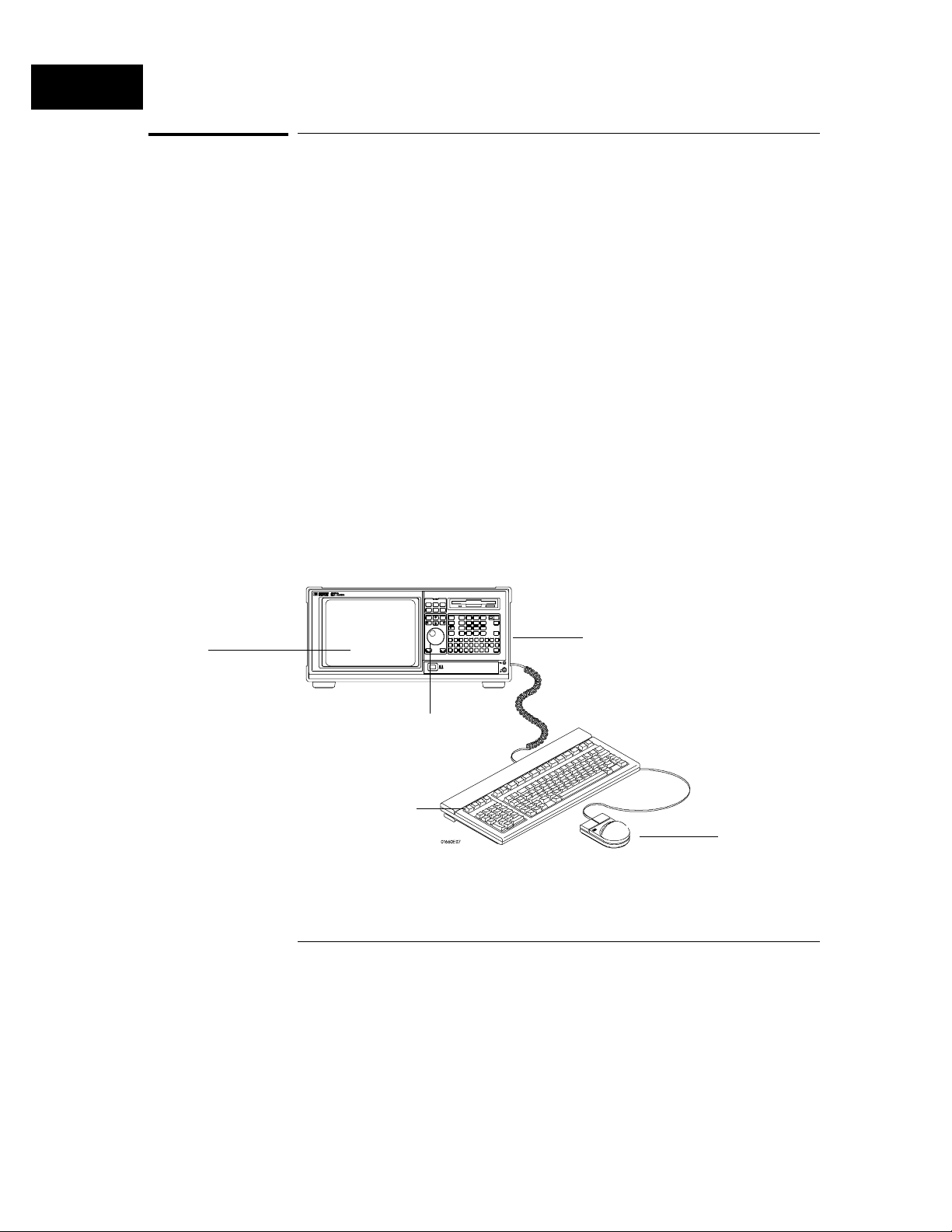
The 1660 Series analyzers have several easy-to-use user interface devices:
the knob, the front panel arrow keys and keypad, the mouse, and the optional
keyboard.
Front panel arrow keys move the highlighter to identify the desired field,
then a front panel Select key is pressed to activate the field. The knob
quickly moves the highlighter (cursor) in certain menus to highlight options
to select and to quickly change numeric assignment fields.
The keypad on the front panel is used to enter alpha and numeric data into
assignment fields. A mouse and an optional full size keyboard are also
available.
To select a field with the mouse, position the cursor (+) of the mouse over
the desired field and press the button on the upper-left corner of the mouse.
The optional keyboard can control all instrument functions by using special
function keys, the arrow keys, and the Enter key. Alpha and numeric entry is
simply typed in.
See Also "Using the Mouse and the Optional Keyboard" found later in this manual for
more information.
"Using the Front-Panel Interface" found later in this manual for more details
on using the standard interface devices.
Alpha and numeric
Display
Knob
Keyboard
Front-Panel Interface Devices
keypads
Mouse
1–4
Page 18
Introduction
Configuration Capabilities
Configuration Capabilities
The five analyzer models in the 1660 Series offer a wide variety of channel
widths and memory depth combinations. The number of data channels range
from 34 channels with the 1664A, up to 136 channels with the 1660A. In
addition, a half channel acquisition mode is available which doubles memory
depth from 4 Kbytes to 8 Kbytes per channel while reducing channel width
by half.
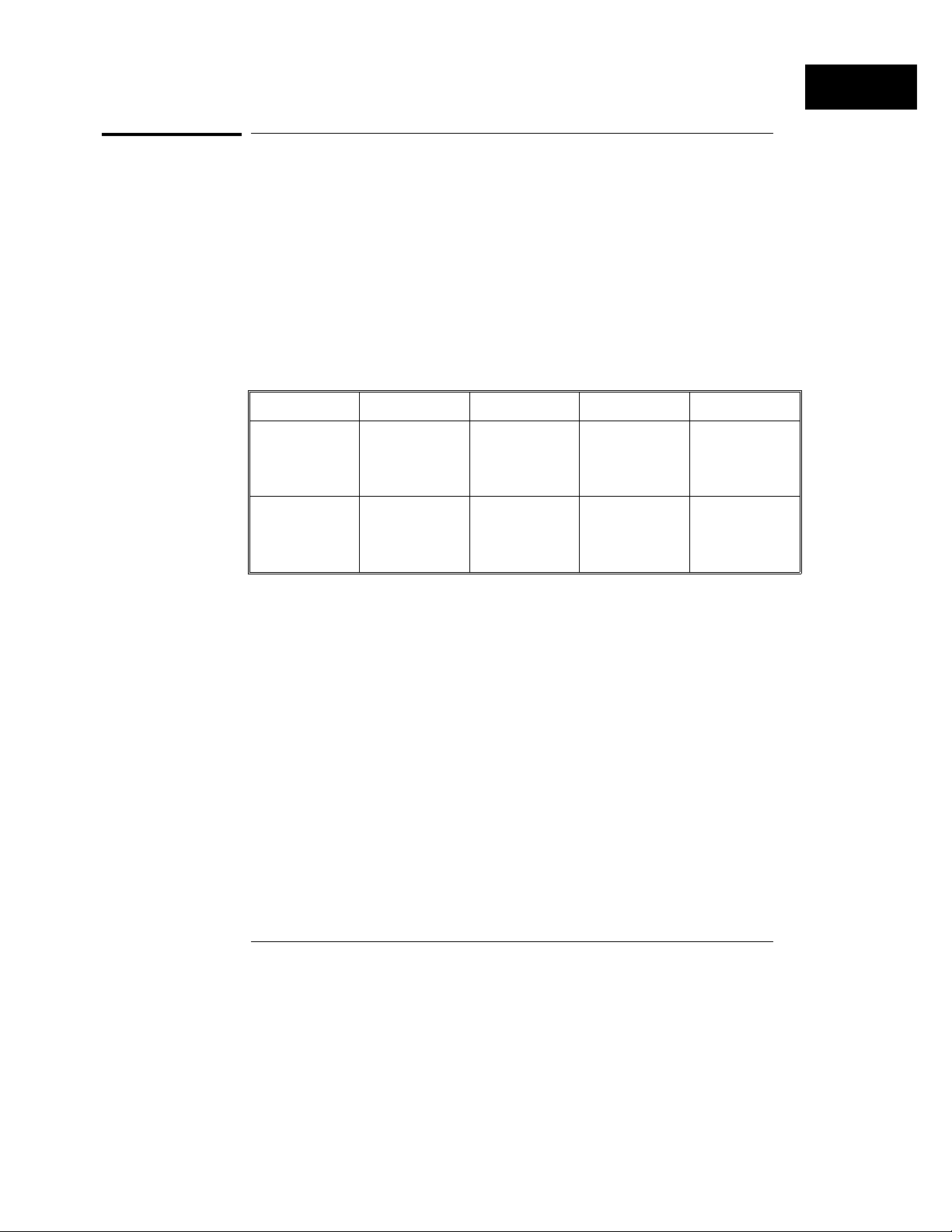
The configuration guide below illustrates the memory depth/channel width
combinations in all acquisition modes with all analyzer models.
State Analyzer Configurations
1660A 1661A 1662A 1663A 1664A
Half channel
50/100 MHz
Full channel
50/100 MHz
8K-deep / 68
chan. 65 data
+
3 data or clock
4K-deep / 136
chan. 130 data
+
6 data or clock
8K-deep / 51
chan. 48 data
+
3 data or clock
4K-deep / 102
chan. 96 data
+
6 data or clock
8K-deep / 34
chan. 32 data
+
2 data or clock
4K-deep / 68
chan. 64 data
+
4 data or clock
8K-deep / 17
chan. 16 data
+
1 data or clock
4K-deep / 34
chan. 32 data
+
2 data or clock
State Analyzer Configuration Considerations
Unused clock channels can be used as data channels.
•
With Time or State tags turned on, memory depth is reduced by half.
•
However, full depth is retained if you leave one pod pair unassigned.
Maximum of 6 clocks in the 1660A model.
•
8K-deep / 17
chan. 16 data
+
1 data or clock
4K-deep / 34
chan. 32 data
+
2 data or clock
1–5
Page 19
Introduction
Configuration Capabilities
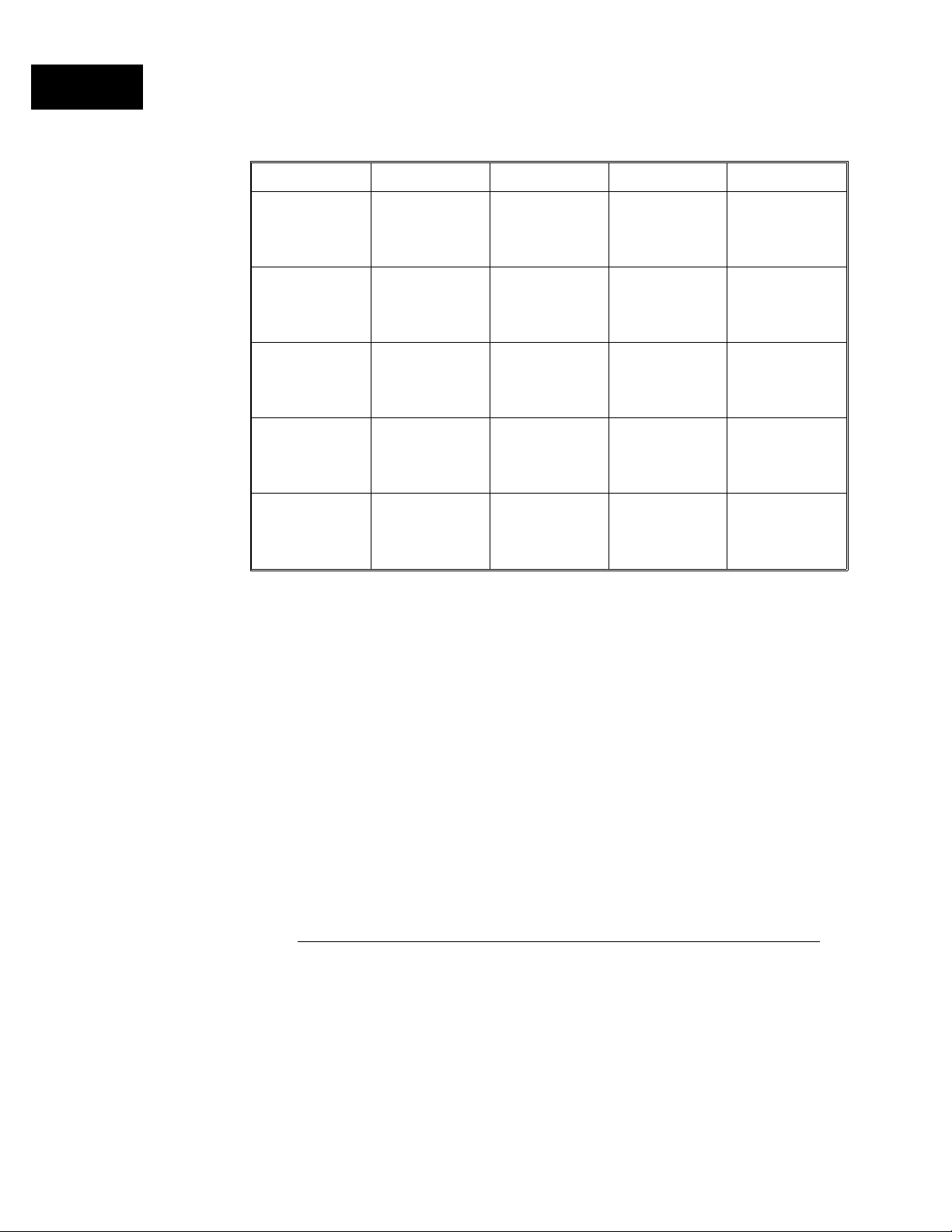
Timing Analyzer Configurations
1660A 1661A 1662A 1663A 1664A
Conventional
half channel 500 MHz
Conventional
full channel 250 MHz
Transitional
half channel 250 MHz
Transitional
full channel 125 MHz
Glitch
half channel 125 MHz
8K-deep / 68
chan. 65 data
+
3 data or clock
4K-deep / 136
chan. 130 data
+
6 data or clock
8K-deep / 68
chan. 65 data
+
3 data or clock
4K-deep / 136
chan. 130 data
+
6 data or clock
4K-deep / 68
chan. 65 data
+
3 data or clock
8K-deep / 51
chan. 48 data
+
3 data or clock
4K-deep / 102
chan. 96 data
+
6 data or clock
8K-deep / 51
chan. 48 data
+
3 data or clock
4K-deep / 102
chan. 96 data
+
6 data or clock
4K-deep / 51
chan. 48 data
+
3 data or clock
8K-deep / 34
chan. 32 data
+
2 data or clock
4K-deep / 68
chan. 64 data
+
4 data or clock
8K-deep / 34
chan. 32 data
+
2 data or clock
4K-deep / 68
chan. 64 data
+
4 data or clock
4K-deep / 34
chan. 32 data
+
2 data or clock
Timing Analyzer Configuration Considerations
Unused clock channels can be used as data channels
•
In Glitch half channel mode, memory is split between data and glitches.
•
8K-deep / 17
chan. 16 data
+
1 data or clock
4K-deep / 34
chan. 32 data
+
2 data or clock
8K-deep / 17
chan. 16 data
+
1 data or clock
4K-deep / 34
chan. 32 data
+
2 data or clock
4K-deep / 17
chan. 16 data
+
1 data or clock
8K-deep / 17
chan. 16 data
+
1 data or clock
4K-deep / 34
chan. 32 data
+
2 data or clock
8K-deep / 17
chan. 16 data
+
1 data or clock
4K-deep / 34
chan. 32 data
+
2 data or clock
4K-deep / 17
chan. 16 data
+
1 data or clock
1–6
Page 20

Introduction
Key Features
Key Features
Key features of the 1660A Series are listed below:
Analyzers
50-MHz (1664A) or 100-MHz state (1660A through 1663A), and 500-MHz
•
timing acquisition speed.
Variety of channel widths ranging from 34 channels with the 1664A, up to
•
136 channels with the 1660A.
Lightweight, passive probes for easy hookup and compatibility with
•
previous Agilent logic analyzers and preprocessors.
GPIB and RS-232C interfaces (1660A through 1663A) or Centronix
•
interface (1664A) for programming and hard copy printouts (GPIB and
RS-232C interfaces are optional on the 1664A).
Variable setup/hold time in the State analyzer.
•
External triggering to/from other instruments through rear-panel BNCs.
•
4 Kbytes-deep memory on all channels with 8 Kbytes-deep in half channel
•
modes.
Marker measurements.
•
Pre-configured trigger macros. 12 levels of trigger sequencing for state
•
and 10 levels of sequential triggering for Timing.
Both state and timing analyzers can use 10 pattern resource terms,
•
2 range terms, and 2 timer/counters to qualify and trigger on data. In
addition, the timing analyzer has 2 edge terms.
50-MHz (1664A) or 100-MHz (1660A through 1663A) time and
•
number-of-states tagging.
Full programmability.
•
State/State and mixed State/Timing displays.
•
Compare, Chart, and Waveform displays.
•
1–7
Page 21

Introduction
Accessories Supplied
Accessories Supplied
The table below lists the accessories supplied with your logic analyzer. If any
of these accessories are missing, contact your nearest Agilent Technologies
sales office.
Accessories Quantity
Probe tip assemblies Note 1
Quick Start Training Kit 1*
Programming Reference 1*
Probe cables Note 2
Grabbers (20 per pack) Note 1
Extra probe leads (5 per pack) Note 3
Operating system disks 1 (Note 4)
User’s Reference 1
Accessories pouch 1
Mouse 1
Note 1 Quantities : 8 - 1660A
6 - 1661A
4 - 1662A
2 - 1663A and 1664A
Note 2 Quantities : 4 - 1660A
3 - 1661A
2 - 1662A
1 - 1663A and 1664A
Note 3 Quantities : 8 - 1660A
6 - 1661A
4 - 1662A
2 - 1663A
0 - 1664A
Note 4 The 1664A requires an Operating System disk for turn-on and boot-up.
Operation of the analyzer is not possible without this disk.
* Standard equipment (or supplied accessory) for all models except the 1664A. Items can be
ordered as an option for the 1664A.
See Also Accessories for Agilent Logic Analyzers if you need additional accessories.
1–8
Page 22

Introduction
Accessories Available
Accessories Available
There are a number of accessories available that will make your measurement
tasks easier and more accurate. You will find these listed in Accessories for
Agilent Logic Analyzers. The table below lists additional documentation
that is available from your nearest Agilent Technologies sales office for use
with your logic analyzer.
Accessories Available Quantity
Quick Start Training Kit 1*
Programming Reference 1*
Service Guide 1
* Standard equipment for all models except the 1664A. Items can be ordered as an option for the
1664A.
Preprocessor Modules
The preprocessor module accessories enable you to quickly and easily
connect the logic analyzer to your microprocessor under test.
Included with each preprocessor module is a 3.5-inch disk which contains a
configuration file and an inverse assembler file. When you load the
configuration file, it configures the logic analyzer for making state
measurements on the microprocessor for which the preprocessor is designed.
Configuration files from other analyzers can also be loaded. For information
on translating other configuration files into the analyzer, refer to the
applicable preprocessor manual.
The inverse assembler file is a software routine that will display captured
information in a specific microprocessor’s mnemonics. The DATA field in the
State Listing is replaced with an inverse assembly field. The inverse
assembler software is designed to provide a display that closely resembles
the original assembly language listing of the microprocessor’s software. It also
identifies the microprocessor bus cycles captured, such as Memory Read,
Interrupt Acknowledge, or I/O Write.
Many of the preprocessor modules require the Agilent Technologies 10269C
General-Purpose Probe Interface. The probe interface accepts the specific
preprocessor PC board and connects it to five connectors on the
general-purpose interface to which the logic analyzer probe cables connect.
1–9
Page 23

Introduction
Accessories Available
See Also Accessories for Logic Analyzers for a list of preprocessor modules and their
descriptions.
1–10
Page 24

2
Probing
Page 25

Probing
This chapter contains a description of the probing system for the logic
analyzer. It also contains the information you need for connecting the
probe system components to each other, to the logic analyzer, and to
the system under test.
Probing Options
You can connect the logic analyzer to your system under test in one of
the following ways:
• Agilent Technologies 10320C User-Definable Interface (optional).
• Microprocessor and bus specific interfaces (optional).
• Standard general-purpose probing (provided).
• Direct connection to a 20-pin, 3M-Series type header connector
using the optional termination adapter.
The 10320C User-Definable Interface
The optional 10320C User-Definable Interface module combined with
the optional Agilent Technologies 10269C General Purpose Probe
Interface allows you to connect the logic analyzer to the
microprocessor in your target system. The 10320C includes a
breadboard that you custom wire for your system.
Another option for use with the interface module is the Agilent
Technologies 10321A Microprocessor Interface Kit. This kit includes
sockets, bypass capacitors, and a fuse for power distribution. Also
included are wire-wrap headers to simplify wiring of your interface
when you need active devices to support the connection requirements
of your system.
See Also Accessories for Agilent Logic Analyzers for additional information
about the interface module and the microprocessor interface kits.
2–2
Page 26

Probing
Microprocessor and Bus Specific Interfaces
There are a number of microprocessor and bus specific interfaces
available as optional accessories that are listed in the Accessories for
Agilent Logic Analyzers. Microprocessors are supported by
Universal Interfaces or Preprocessor Interfaces, or in some cases, both.
Universal Interfaces are aimed at initial hardware turn-on, and will
provide fast, reliable, and convenient connections to the
microprocessor system.
Preprocessor interfaces are aimed at hardware turn-on and
hardware/software integration, and will provide the following:
• All clocking and demultiplexing circuits needed to capture the
system’s operation.
• Additional status lines to further decode the operation of the CPU.
• Inverse assembly software to translate logic levels captured by the
logic analyzer into microprocessor mnemonics.
Bus interfaces will support bus analysis for the following:
• Bus support for GPIB, RS-232C, RS-449, SCSI, VME, and VXI.
General-Purpose Probing
General-purpose probing involves connecting the logic analyzer
probes directly to your target system without using any interface.
General-purpose probing does not limit you to specific hookup
schemes, for an example, as the probe interface does.
General-purpose probing uses grabbers that connect to both through
hole and surface mount components. General-purpose probing comes
as the standard probing option. You will find a full description of its
components and use later in this chapter.
The Termination Adapter
The optional termination adapter allows you to connect the logic
analyzer probe cables directly to test ports on your target system
without the probes.
2–3
Page 27
Probing
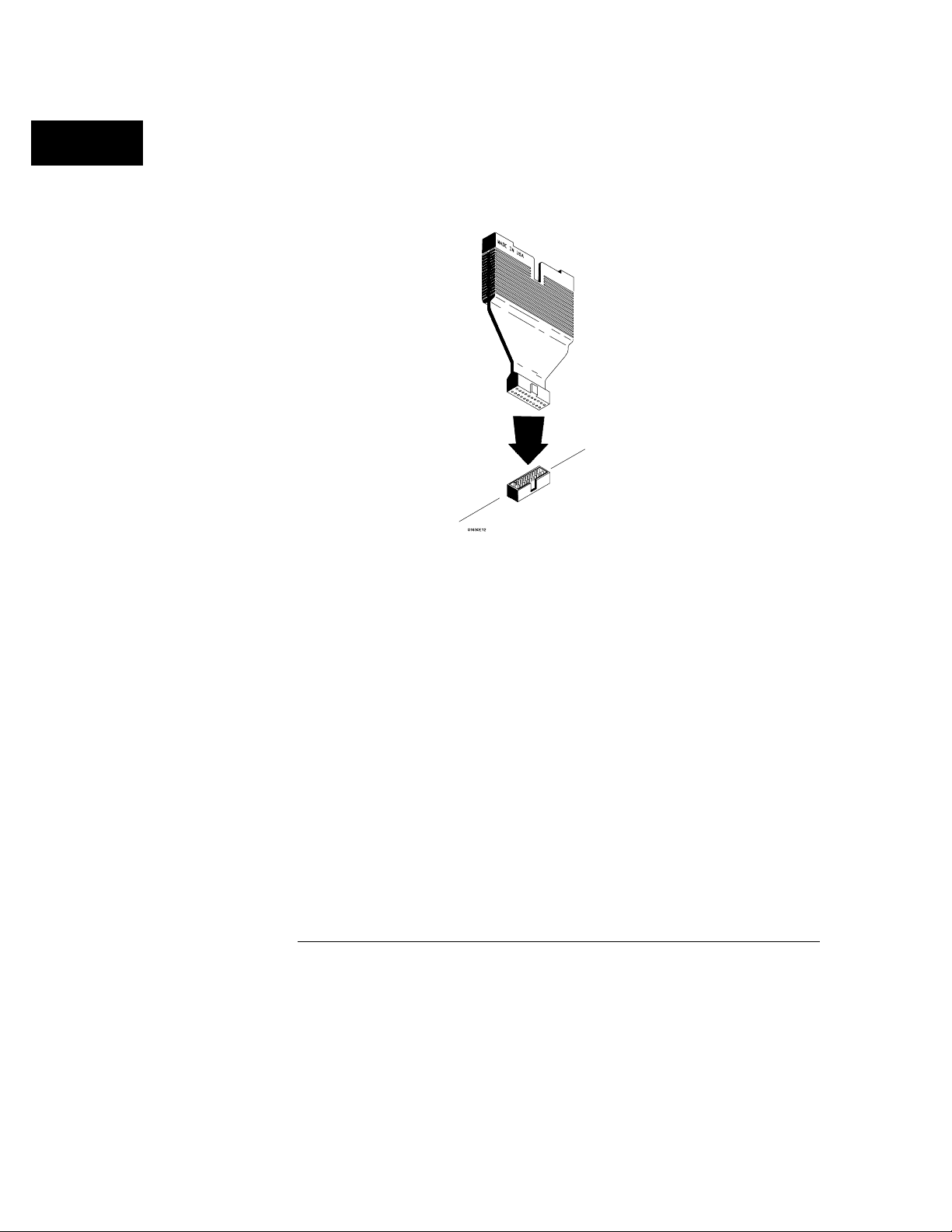
The termination adapter is designed to connect to a 20 (2x10)
position, 4-wall, low-profile, header connector which is a 3M-Series
3592 or equivalent.
Termination Adapter
2–4
Page 28
Probing
General-Purpose Probing System Description
General-Purpose Probing System Description
The standard probing system provided with the logic analyzer consists of a
probe tip assembly, probe cable, and grabbers. Because of the passive design
of the probes, there are no active circuits at the outer end of the cable. The
rest of this chapter is dedicated to general-purpose probing.
The passive probing system is similar to the probing system used with
high-frequency oscilloscopes. It consists of a series RC network
(90 kΩ in parallel with 8 pF) at the probe tip, and a shielded, resistive
transmission line. The advantages of this system include the following:
250 Ω in series with 8-pF input capacitance at the probe tip for minimal
•
loading.
Signal ground at the probe tip for high-speed timing signals.
•
Inexpensive, removable probe tip assemblies.
•
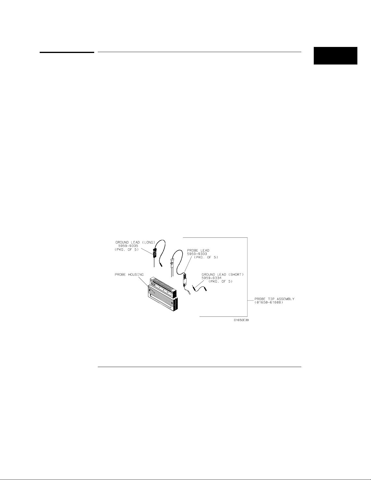
Probe Tip Assemblies
Probe tip assemblies allow you to connect the logic analyzer directly to the
target system. This general-purpose probing is useful for discrete digital
circuits. Each probe tip assembly contains 16 probe leads (data channels),
1 clock lead, a pod ground lead, and a ground tap for each of the 16 probe
leads.
Probe Tip Assembly
2–5
Page 29
Probing
General-Purpose Probing System Description
Probe and Pod Grounding
Each pod is grounded by a long, black, pod ground lead. You can connect the
ground lead directly to a ground pin on your target system or use a grabber.
To connect the ground lead to grounded pins on your target system, you
must use 0.63-mm (0.025-in) square pins, or use round pins with a diameter
of 0.66 mm (0.026 in) to 0.84 mm (0.033 in). The pod ground lead must
always be used.
Each probe can be individually grounded with a short black extension lead
that connects to the probe tip socket. You can then use a grabber or the
grounded pins on your target system in the same way you connect the data
lines.
When probing signals with rise and fall times of ≤ 1 ns, grounding each probe
lead with the 2-inch ground lead is recommended. In addition, always use
the probe ground on a clock probe.
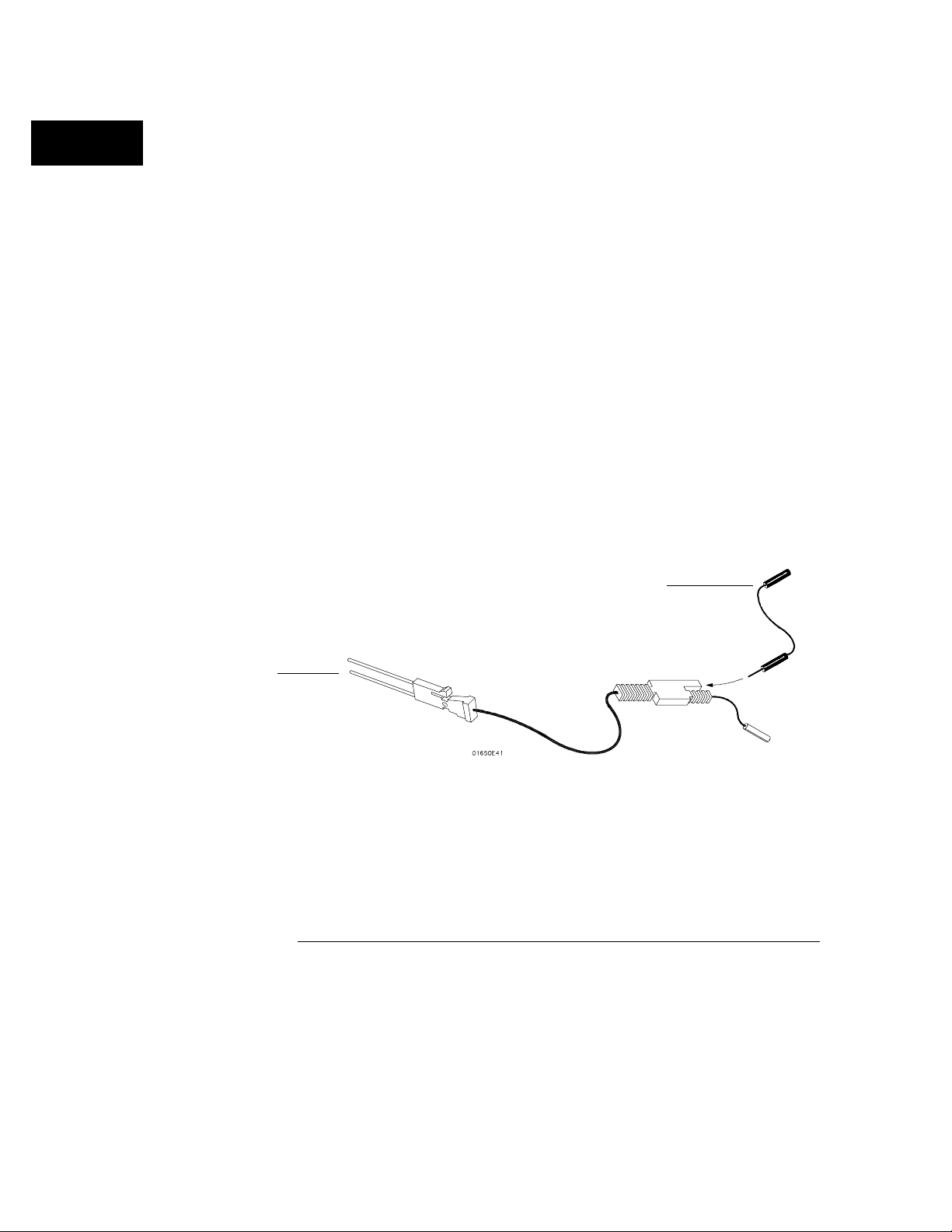
Probe Leads
The probe leads consists of one 12-inch, twisted-pair cable; one ground tap;
and one grabber. The probe lead, which connects to the target system, has
an integrated RC network with an input impedance of 100 kΩ in parallel with
approximately 8 pF, and all in series with 250 Ω. The probe lead has a
two-pin connector on one end that snaps into the probe housing.
Probe lead connector
Probe ground
Probe Ground Lead
2–6
Page 30

CAUTION
NOTE
Probing
General-Purpose Probing System Description
Grabbers
The grabbers have a small hook that fits around the IC pins and component
leads. The grabbers have been designed to fit on adjacent IC pins on either
through hole or surface mount components with lead spacing greater than or
equal to 0.050 inches.
Probe Cable
The probe cable contains 18 signal lines, 17 chassis ground lines and two
power lines for preprocessor use. The cables are woven together into a flat
ribbon that is 4.5 feet long. The probe cable connects the logic analyzer to
the pods, termination adapter, Agilent Technologies 10269C General-Purpose
Probe Interface, or preprocessor. Each cable is capable of carrying 0.33
amps for preprocessor power.
DO NOT exceed this 0.33 amps per cable or the cable will be damaged.
Preprocessor power is protected by a current limiting circuit. If the current
limiting circuit is activated, the fault condition must be removed. After the
fault condition is removed, the circuit will reset in one minute.
1663A and 1664A analyzers use the same pod labels.
Minimum Signal Amplitude
Any signal line you intend to probe with the logic analyzer probes must
supply a minimum voltage swing of 500 mV to the probe tip. If you measure
signal lines with a voltage swing of less than 500 mV, you may not obtain a
reliable measurement.
Maximum Probe Input Voltage
The maximum input voltage of each logic analyzer probe is ±40 volts peak.
Pod Thresholds
Logic analyzer pods have two preset thresholds and a user-definable pod
threshold. The two preset thresholds are ECL (−1.3 V) and TTL (+1.5 V).
The user-definable threshold can be set anywhere between −6.0 volts
and +6.0 volts in 0.05 volt increments.
All pod thresholds are set independently.
2–7
Page 31
Probing
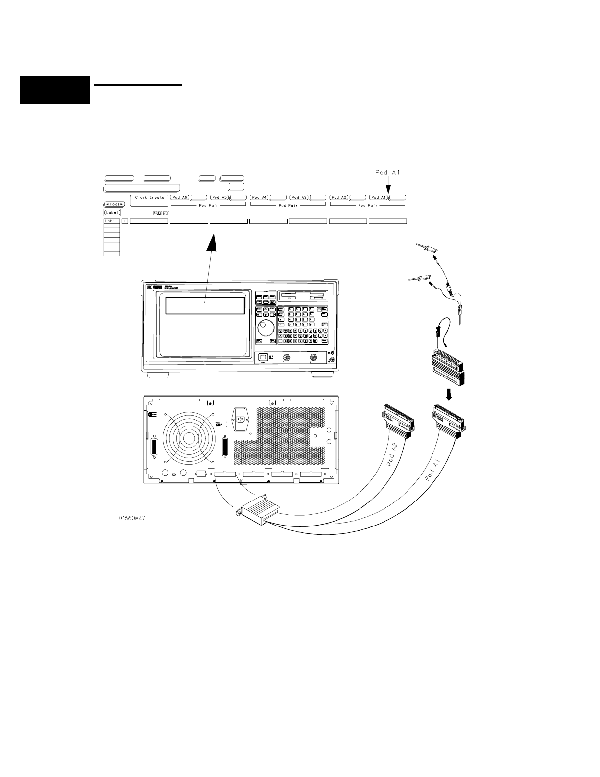
Assembling the Probing System
Assembling the Probing System
The general-purpose probing system components are assembled as shown to
make a connection between the measured signal line and the pods displayed
in the Format menu.
Connecting Probe Cables to the Logic Analyzer
2–8
Page 32
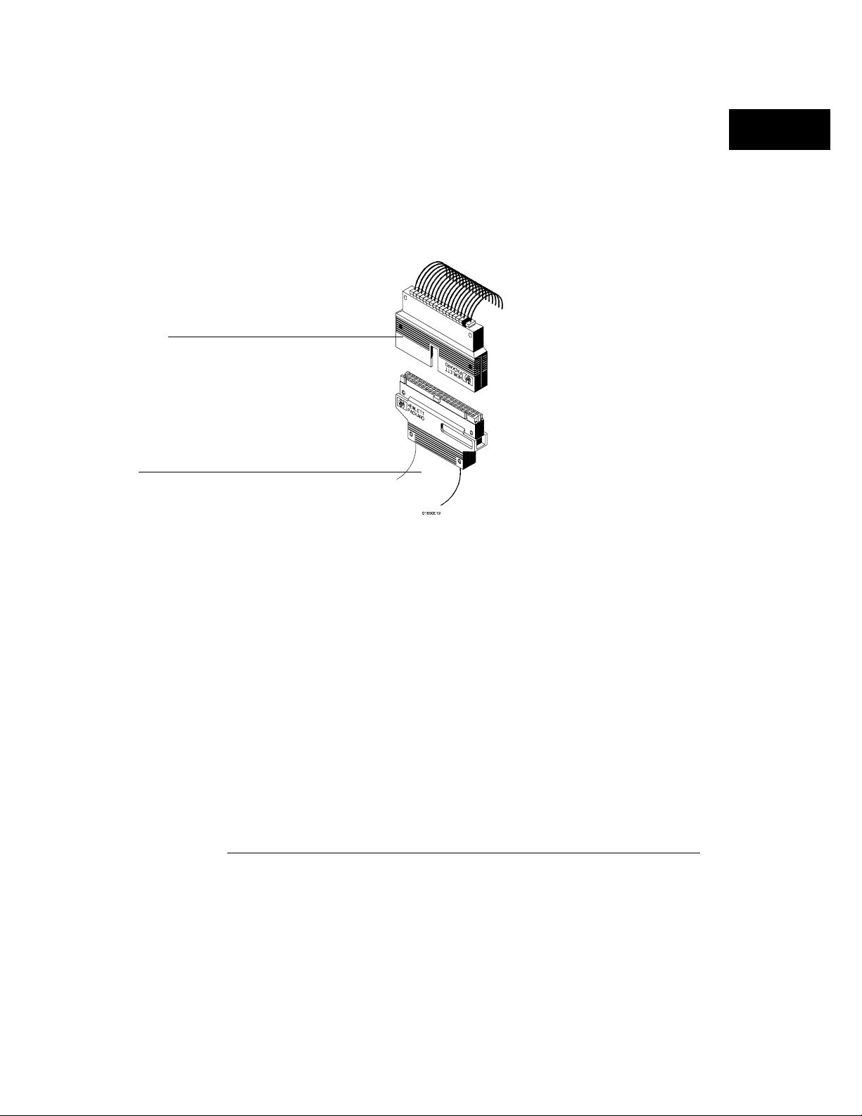
Probe tip assembly
Probing
Assembling the Probing System
Connecting Probe Cables to the Logic Analyzer
All probe cables are installed at the factory. If you need to replace a probe
cable, refer to the Service Guide that is supplied with the logic analyzer.
Connecting the Probe Tip Assembly to the Probe Cable
To connect a probe tip assembly to a cable, align the key on the cable
connector with the slot on the probe housing and press them together.
Probe cable
Connecting Probe Tip Assembly
2–9
Page 33
Probing
Assembling the Probing System
Disconnecting Probe Leads from Probe Tip Assemblies
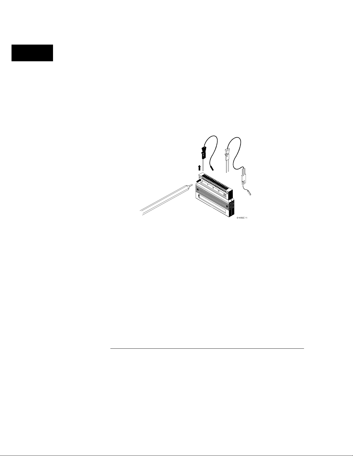
When you receive the logic analyzer, the probe leads are already installed in
the probe tip assemblies. To keep unused probe leads out of your way during
a measurement, you can disconnect them from the pod.
To disconnect a probe, insert the tip of a ball-point pen into the latch
opening. Push on the latch while gently pulling the probe out of the pod
connector as shown in the figure.
To connect the probes into the pods, insert the double pin end of the probe
into the probe housing. Both the double pin end of the probe and the probe
housing are keyed so they will fit together only one way.
Installing Probe Leads
2–10
Page 34
Probing
Assembling the Probing System
Connecting the Grabbers to the Probes
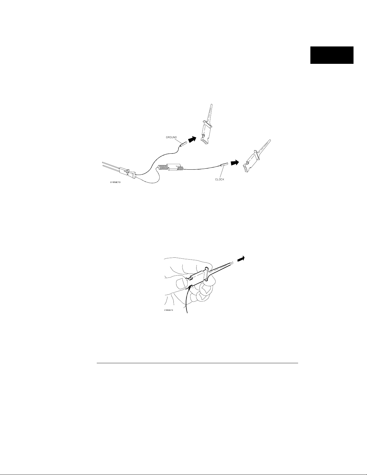
Connect the grabbers to the probe leads by slipping the connector at the end
of the probe onto the recessed pin located in the side of the grabber. If you
need to use grabbers for either the pod or the probe grounds, connect the
grabbers to the ground leads in the same manner.
Connecting Grabbers to Probes
Connecting the Grabbers to the Test Points
The grabbers have a hook that fits around the IC pins and component leads.
Connect the grabber to the test point by pushing the rear of the grabber to
expose the hook. Hook the lead and release your thumb as shown.
Connecting Grabbers to Test Points
2–11
Page 35

Probing
Assembling the Probing System
2–12
Page 36

3
Using the Front-Panel Interface
Page 37

The Front-Panel Interface
This chapter explains how to use the front-panel user interface. The
front and rear-panel controls and connectors are explained in the first
part of this chapter followed by a series of "How to Use" examples.
The front-panel interface consists of front-panel keys, a knob, and a
display. The interface allows you to configure the instrument by
moving between menus and setting parameters within the menus.
The interface then displays the measurement results. In general,
using the front-panel interface involves the following processes:
• Selecting the desired menu with the MENU keys.
• Placing the cursor on the desired field by using the arrow keys and
by rotating the knob.
• Selecting and displaying the field options or current data by
pressing the Select key.
• If necessary, selecting lower level options or entering new data by
using the knob, arrow keys, or the keypad.
• Starting and stopping data acquisition by using the Run and Stop
keys.
If you want to step through the examples on using the interface,
simply turn the power Off, then back On. Start with the section,
"How to Select Menus."
3–2
Page 38
Using the Front-Panel Interface
Front-Panel Controls
Front-Panel Controls
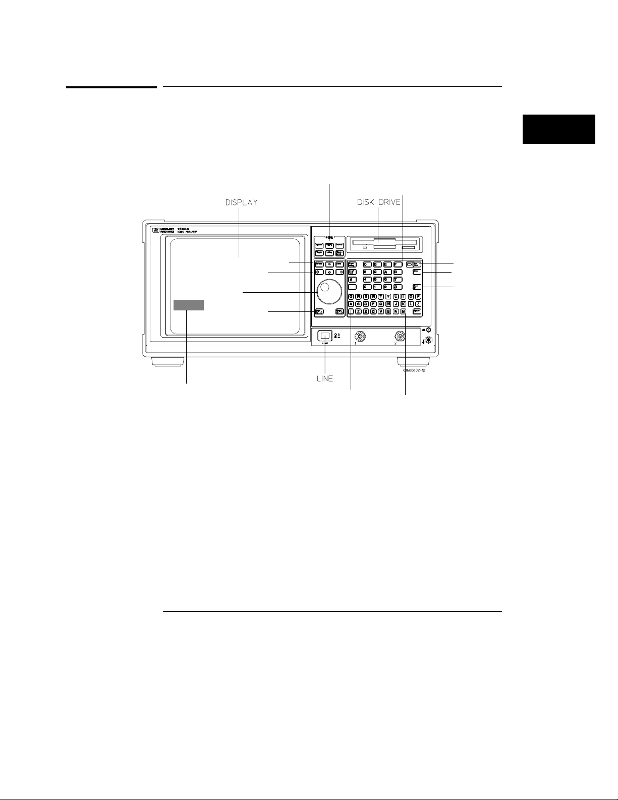
In order to apply the user interface quickly, you should know what the
following front-panel controls do.
Clear entry key
Don’t Care key
+/- key
. key
Hexadecimal
keypad
Front-Panel Layout
Cursor
Menu keys
Select/Done keys
Arrow keys
Knob
Page keys
Shift key
Alpha keypad
Run/Continue
key
Stop key
Print/All
key
The Cursor
The cursor (inverse video field) highlights interactive fields within the menus
that you want to use. Interactive fields are enclosed in boxes in each menu.
When you press the arrow keys, the cursor moves from one field to another.
MENU Keys
The menu keys allow you to quickly select the main menus in the logic
analyzer. These keys are System, Config, Format, Trigger, List, and
Waveform. The System key accesses the system menu. The Config, Format,
Trigger, List, and Waveform keys will display the menus of either analyzer
(machine) 1 or 2 respectively depending on what menu was last displayed.
3–3
Page 39

Using the Front-Panel Interface
Front-Panel Controls
System Menu Key The System key allows you to access the System
subset menus. The subset menus are the Disk, RS-232 / GPIB
(Printer/Controller for 1664A), Utilities, and Test menus.
Config Menu Key The Config menu key allows you to access either
the Timing or State Configuration menu. You exit the Config menu by
pressing another menu key.
Format Menu Key The Format menu key allows you to access either
the Timing or State Format menu. You exit the Format/Display menu by
pressing another menu key.
Trigger Menu Key The Trigger menu key allows you to access either
the Timing or State Trigger menu. You exit the Trigger menu by
pressing another menu key.
List Menu Key The List menu key allows you to access either the
Timing or State Listing menu. In addition, if the List key is pressed a
second time, the Compare menu becomes available. The available menus
depend on the type of analyzers turned on and what analyzer was
accessed last. You exit the List menu by pressing another menu key.
Waveform Menu Key The Waveform menu key allows you to access
either the Timing or State Waveform menu. In addition, if the Waveform
key is pressed a second time, the Chart menu becomes available. The
available menus depends on the type of analyzers turned on and what
analyzer was accessed last. You exit the Waveform menu by pressing
another menu key.
Select Key
The Select key initiates an interface action that is dictated by the field
currently highlighted. The highlighted field could be an option field within a
pop-up, a toggle field, an assignment field, or a Done field. For example, if
the field is a Done field, you just press the Select key to finish that task.
When option fields are selected, they either save the highlighted selection
into the configuration, or they access other pop-ups requiring another
selection or assignment. When you select an option, the pop-up either closes
automatically with the Select key or it closes when you select the Done field.
When toggle fields are selected, the field will automatically switch to the
other choice.
3–4
Page 40

Using the Front-Panel Interface
Front-Panel Controls
When you select an assignment field, it opens. When the Select key is
pressed in an opened assignment field, either a highlighted option is
assigned, or keypad entries are assigned. Then the assignment field closes.
Done Key
The Done key stops any field selection and assignment actions by saving the
current selections and closing the opened pop-up. In some fields, its action is
the same as the Select key.
Arrow Keys
The arrow keys move the cursor around the menu in a horizontal and vertical
direction, according to the direction of the arrow.
Knob
The knob has four major functions, depending on what field or pop-up menu
you are in. The knob allows you to do the following:
Increment/decrement numeric values in numeric pop-up menus.
•
Roll the offscreen display containing such things as data listings,
•
waveforms, the resource term list, sequence level list, or labels. Depending
on what display is rolled, the direction can be left, right, up, or down.
Move the cursor from option to option within a selection list.
•
Move the cursor from field to field within an assignment field.
•
Page Keys
The Page keys roll offscreen display data such as pods, labels, resource
terms, data listings, and waveforms one screen at a time. To roll data in an
up and down direction, press the up or down Page keys. To roll data in a left
to right direction, press the blue shift key prior to the left or right Page key.
When the blue shift key is pressed followed by a left or right arrow key, only
one page roll occurs. For multiple left or right paging, you must repeat the
two-key process.
If there are multiple items in a menu that need paging, the field containing
the item name turns dark indicating it is rollable. The Page keys work
independant of the knob. If there are up and down rollable data, simply press
the up or down front-panel Page keys. If there are left and right rollable data,
press the blue shift key, then the left or right Page key (Shift+Page). This
two-key sequence is repeated for each paged screen.
3–5
Page 41

Using the Front-Panel Interface
Front-Panel Controls
Run/Rep Key
The Run key starts a data acquisition in any run mode you specify. After the
acquisition, the analyzer (state or timing) is automatically forced into the last
display menu accessed.
To start a single run, press the Run/Rep key. To start a Repetitive run, press
the blue shift key, then press the Run/Rep key.
Stop key
The Stop key allows you to stop data acquisition or printing. After the
acquisition is stopped, the data displayed onscreen depends on which run
mode (single or repetitive) was used to acquire the data. In the repetitive
mode, Stop halts acquisition after the last completed single acquisition cycle.
In single mode, Stop causes the single data acquisition to be aborted and
partial data is displayed. If you print a hard copy, the Stop key stops the print.
Print/All Key
The Print/All key starts a hard copy print of the screen and any data that
appears on that screen. To print all data that is offscreen, press the blue shift
key prior to pressing the Print/All key.
Don’t Care Key
The Don’t Care key allows you to enter don’t cares (Xs) in binary, octal, and
hexadecimal pattern assignment fields. In Alpha Entry fields, this key enters
a space and moves the underscore marker to the next space.
Clear Entry Key
The Clear entry key allows you to clear assignment fields of alpha entries,
channel assignments, and numeric entries. When you press the Clear entry
key in an alpha assignment field, a cursor appears that indicates the start
point for new alpha entry.
± Key
The ± key allows you to change the sign (±) of numeric variables.
. (period) Key
The period key allows you to enter a period in a numeric entry, turn off a
channel assignment, or enter a period in an alpha assignment.
3–6
Page 42

Using the Front-Panel Interface
Front-Panel Controls
Hexadecimal Keypad
The hexadecimal keypad allows you to enter numeric values in numeric entry
fields. You enter values in the four number bases Binary, Octal, Decimal, and
Hexadecimal. The A through F keys are used for both hexadecimal and alpha
character entries.
Alpha Keypad
The alpha keypad allows you to enter letters in alpha entry fields. You enter
letters in fields where a custom name is desired.
Disk Drive
The disk drive is a 3.5 inch, double-sided, double density drive. Besides
loading the operating system, it allows you to store and load logic analyzer
configurations and inverse assembler files. There is a disk eject button
located on the right side. Press this button to eject a flexible disk from the
disk drive. The disk drive also has an indicator light. This light is illuminated
when the disk drive is operating. Wait until this light is out before removing
or inserting disks.
On 1664A analyzers, the operating system is not contained on ROM inside of
the unit, and MUST be loaded from disk when the 1664A is powered up.
Simply insert the operating system disk into the disk drive, then set the LINE
switch to ON.
3–7
Page 43
Using the Front-Panel Interface
Rear-Panel Controls and Connectors
Rear-Panel Controls and Connectors
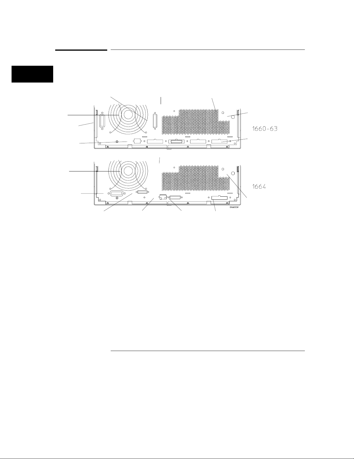
In order to apply the user interface quickly, you should know what the
following rear-panel controls do:
Fan
GPIB
Connector
Keyboard
and Mouse
Connector
Fan
GPIB
Connector
(Optional)
Rear Panel Layout
RS-232C Connector
RS-232C
Connector
(Optional)
Line Power Module
Permits selection of 110-120 or 220-240 Vac and contains the fuses for each
of these voltage ranges.
Line Power Module
Line Power Module
Keyboard
and Mouse
Connector
Parallel Printer
Connector
Intensity Control
External Trigger
BNCs
Pod Cable
Connectors
Intensity
Control
External Trigger
BNCs
Pod Cable
Connector
External Trigger BNCs
The External Trigger BNCs provide arm out and arm in connections. When
the Arming Control is configured in the Trigger menu, the Arm In signal
enters through the External Trigger In BNC and the Arm Out signal
generated by the analyzer leaves through the External Trigger Out BNC.
3–8
Page 44

Using the Front-Panel Interface
Rear-Panel Controls and Connectors
Intensity Control
Allows you to set the display brightness to a comfortable level.
Pod Cable Connectors
These are keyed connectors for connecting the pod cables. Depending on
the analyzer model, you will see a different number of pod cables.
RS-232C Connector
Standard DB-25 type connector for connecting an RS-232C printer or
controller. This interface is standard on the 1660A through 1663A, and
optional on the 1664A.
GPIB Connector
Standard GPIB connector for connecting an GPIB printer or controller. This
interface is standard on the 1660A through 1663A, and optional on the 1664A.
Parallel Printer Port Connector
Standard DB-25 type connector for connecting a Centronix printer to the
1664A. This interface is not available on the 1660A through 1663A.
Keyboard and Mouse Connector
Standard keyboard/mouse connector for connecting an optional keyboard
and/or mouse.
Fan
Provides cooling for the logic analyzer. Make sure air is not restricted from
the fan and rear-panel openings.
3–9
Page 45
Using the Front-Panel Interface
How to Power-up The Analyzer
How to Power-up The Analyzer
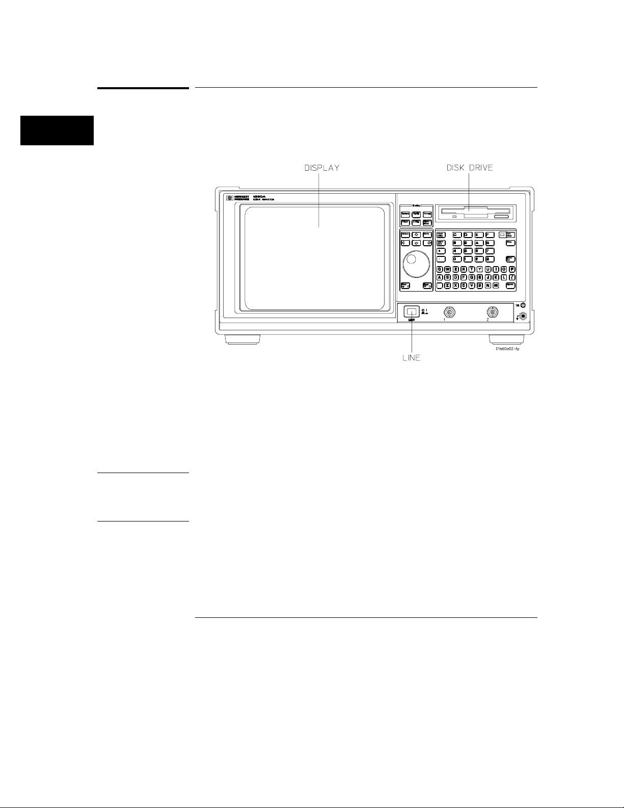
The method for powering up the analyzer is dependent on the model.
For the 1660A through 1663A, simply set the front panel LINE switch to ON.
Power On Procedure
For the 1664A, proceed as follows:
1 Insert the Operating System disk into the disk drive.
2 Set the front panel LINE switch to ON.
3 Verify "Loading System File" is displayed. If "System Disk Not
Found" is displayed, repeat procedure using the correct Operating
System disk.
NOTE It is recommended that a working copy of the master Operating System disk
be made (using the "Duplicate Disk" function in the System Menu) and used
for normal operation. Place the master Operating System disk in a safe
location, for use when the working copy is damaged or lost.
3–10
Page 46
Using the Front-Panel Interface
How to Select Menus
How to Select Menus
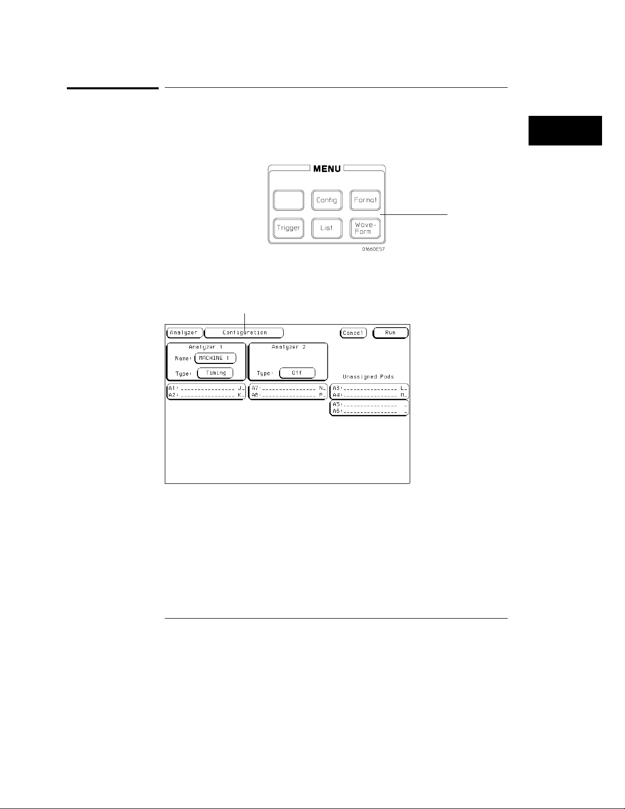
There are two ways of selecting menus.
1 Press any one of the five front-panel MENU keys.
MENU keys
2 Or, press the front-panel arrow keys and move the cursor to the menu
Name field as shown below, then press the
Menu name field
Select key.
Menu Name Field
If more than one analyzer is on, you see the selected menu of analyzer 1 or
analyzer 2 depending on what type menu was last displayed. To switch from
the machine 1 menu set to machine 2 menu set, highlight the Menu name
field, then press the Select key. Now, select analyzer 2 and the menu you
want from the pop-up menu.
3–11
Page 47
Menu selection list
(not shown on the
1664A)
Using the Front-Panel Interface
How to Select Menus
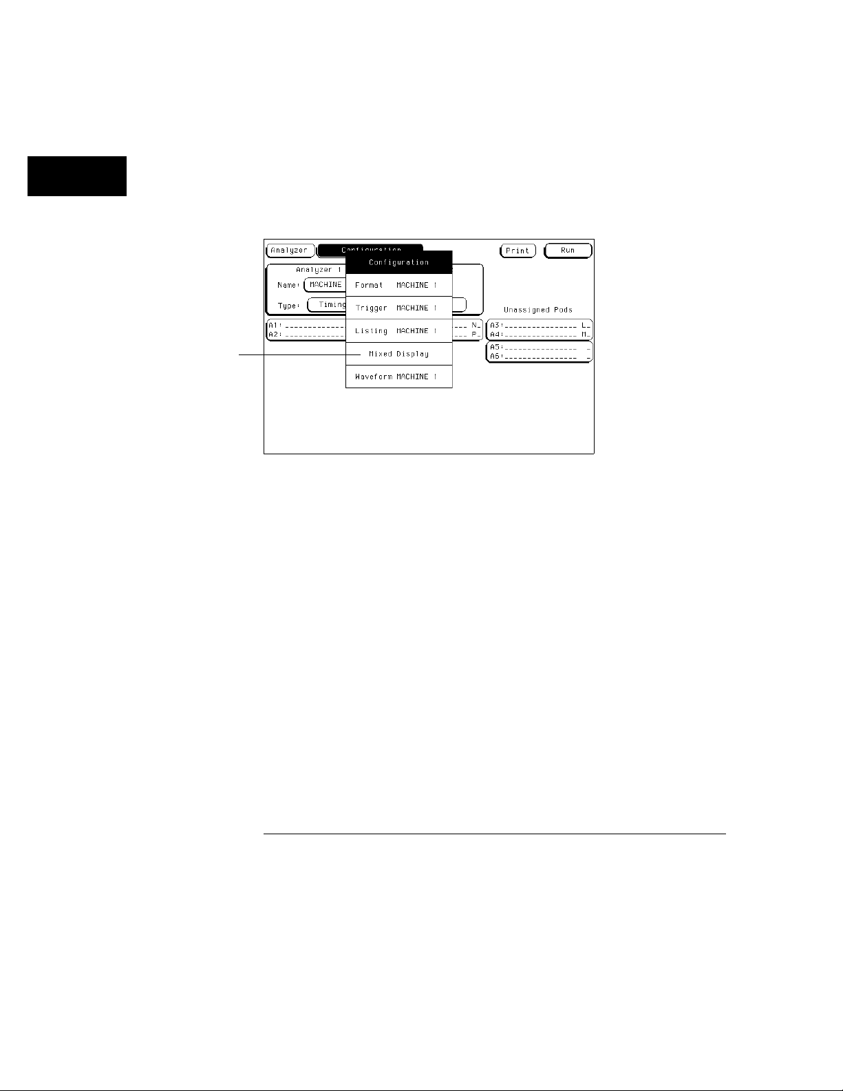
3. Press the Up/Down arrow keys or turn the knob to highlight the desired
menu name as shown below, then press the
Select key.
In many applications, both analyzers are turned on. In these cases, if a
front-panel MENU key is pressed twice, all corresponding menus for that
MENU key become available.
Complete Menu Selection List
3–12
Page 48
System key
Using the Front-Panel Interface
How to Select the System Menus
How to Select the System Menus
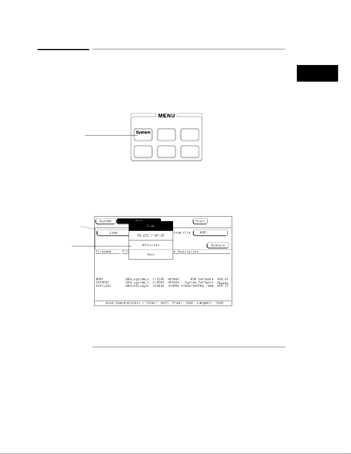
One of the six MENU keys is the System key. You use the System key to
access a set of menus that are used to configure system level parameters for
the I/O bus, clock, display, and the disk drive operations. To access the
menus under the System key, perform the following steps:
Press the System MENU key.
1
2 Press the arrow keys to highlight the menu Name field, then press the
Select key.
3 Press the Up/Down arrow keys or turn the knob to highlight the desired
System menu name as shown below, then press the
Select key.
1660A through
1663A shown.
1664A displays
"Printer/Controller"
System menu
Selection List
Menu name field
System Menus Selection List
3–13
Page 49
Using the Front-Panel Interface
How to Select the System Menus
To return to one of the analyzer menus, do the following:
4 Press any of the five MENU keys.
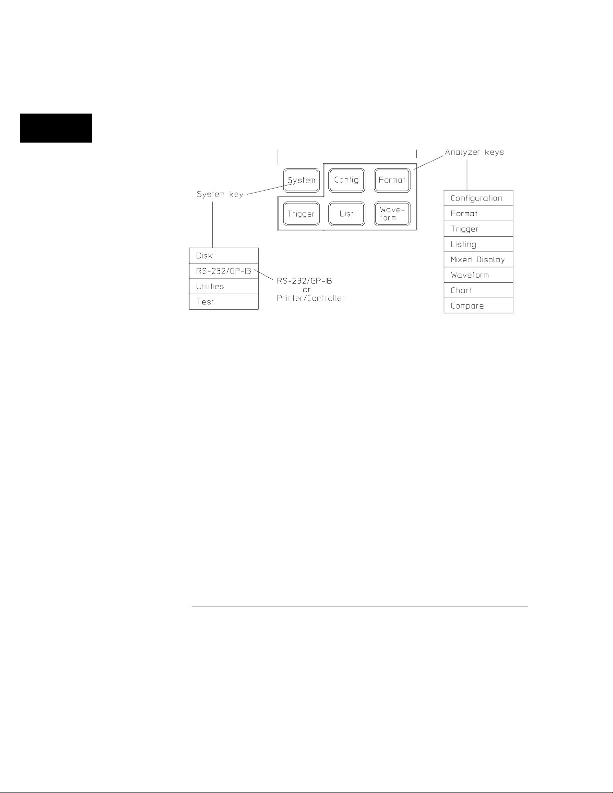
Another way to look at the System menu set and the analyzer menu set is
shown.
System and Analyzer Menu Sets
3–14
Page 50
Using the Front-Panel Interface
How to Select Fields
How to Select Fields
The process of selecting individual fields within the main menus is simply to
highlight the desired field and then press the Select key. However, depending
on what type of field you select, you will either see a pop-up menu appear, or
will see an immediate assignment in a toggle type field.
Pop-up Menus
The pop-up menu is the most common type of menu you see when you select
a field. When a pop-up appears, you see a list of two or more options. The
pop-up closes after at least one of the options are selected. The following
example guides you through field selection within a pop-up menu.
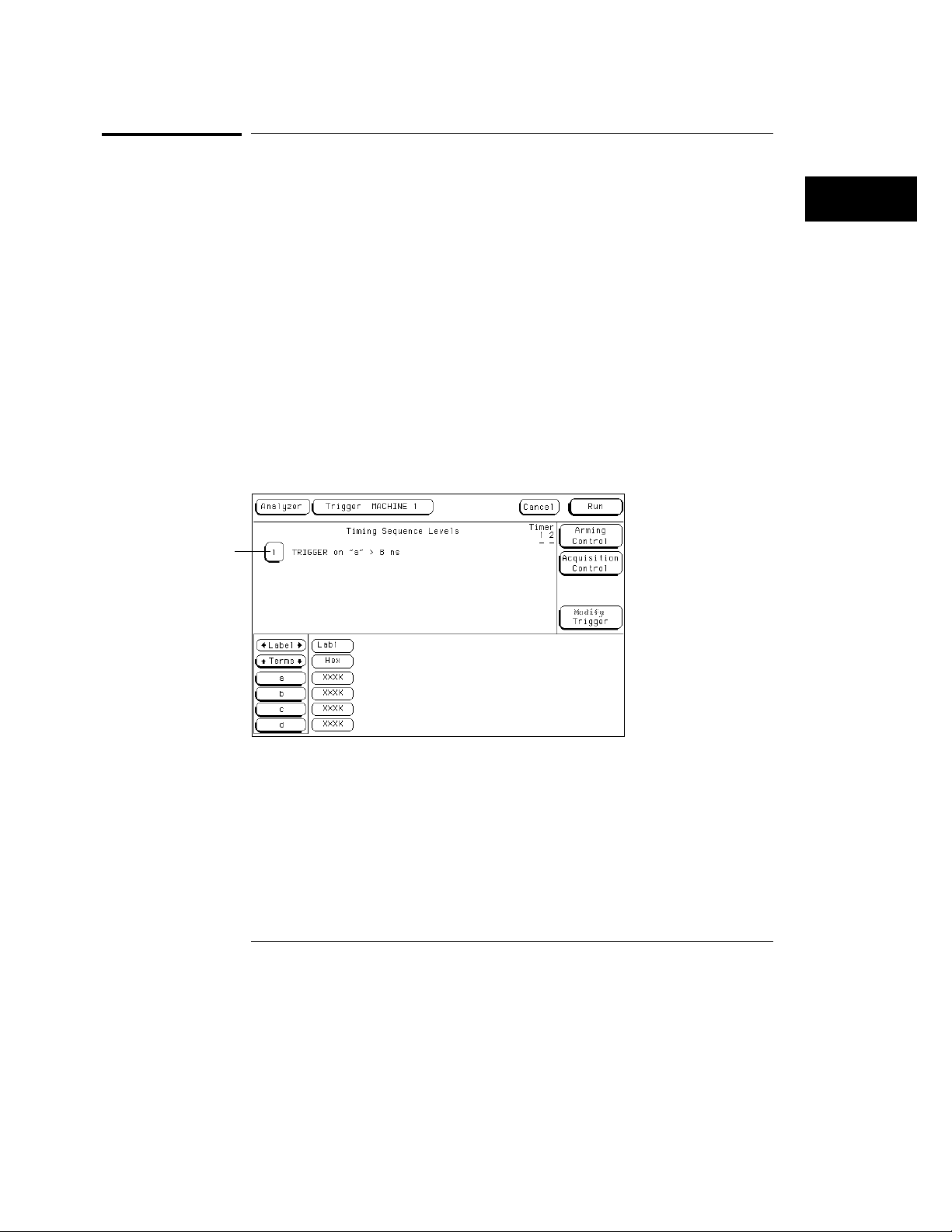
Press the front panel analyzer Trigger MENU key.
1
2 Press the arrow keys to highlight the sequence level 1 field as shown,
then press the
Select key.
Timing sequence level
number 1 field
Sequence Level 1
3–15
Page 51
"Trigger on" field
Using the Front-Panel Interface
How to Select Fields
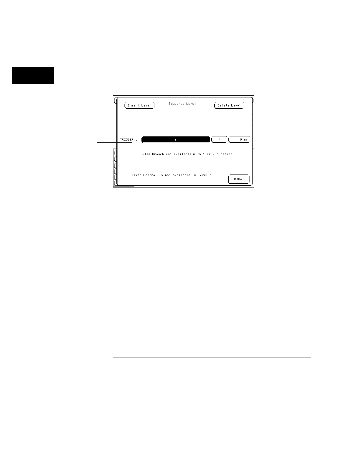
3 Press the arrow keys to highlight the "Trigger on" field as shown, then
press the
A second pop-up appears with all the variable choices for the "Trigger on"
field.
Select key.
"Trigger on" Field
4 Press the arrow keys or turn the knob to highlight any variable field,
then press either the front panel
Pop-up menus of this type do not contain a Done field. They close
automatically when you press either the Select key or the Done key, but do
not close the original pop-up.
To Close the original pop-up press the Done key.
5
You can also close the original pop-up by moving the cursor to the Done field
within the pop-up and pressing the Select key.
3–16
Done or Select keys.
Page 52
Polarity field
Using the Front-Panel Interface
How to Select Fields
Toggle Fields
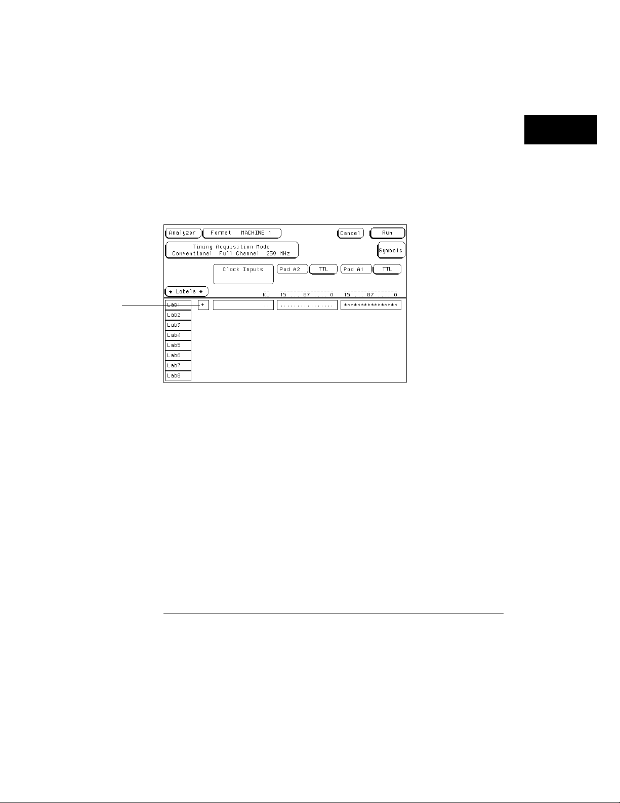
Some fields will simply toggle between two options (like, On/Off). The
following example illustrates a toggle field in the Format menu.
Press the Format MENU key.
1
2 Press the arrow keys to highlight the Polarity field as shown below,
then press the
The Polarity field toggles between positive (+) and negative (−) each time
you press the Select key. You can also toggle this particular field with the
front-panel ± key.
Select key.
Polarity Toggle Field
3–17
Page 53
Using the Front-Panel Interface
How to Configure Options
How to Configure Options
With one exception, the process of selecting an option within a pop-up menu
is the same as selecting any typical field in a main menu. When an option is
selected, it may be necessary to access several pop-up menus before all the
parameters of an option are configured. An example of selecting options is
illustrated in the analyzer Trigger menu.
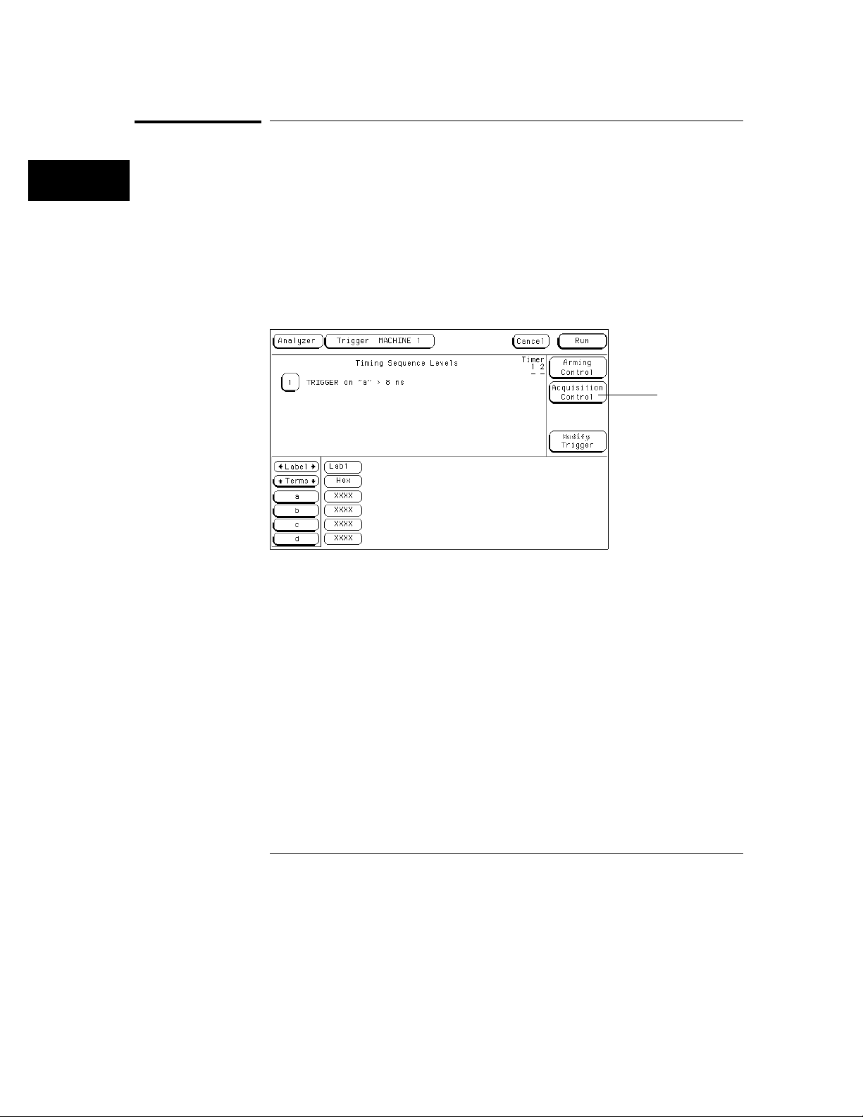
Press the analyzer Trigger MENU key.
1
2 Press the arrow keys to highlight the Acquisition Control field as
shown, then press the
Select key.
Acquisition control
field
Acquisition Control Field
3 With the Acquisition Mode Automatic field highlighted, press the
Select key.
By selecting the Acquisition Mode Automatic field, you toggle the field to
manual operation where you can configure features like the trigger position
and sample rate.
Press the arrow keys to highlight the Trigger Position Field, then press
4
Select key.
the
5 Press the Up/Down arrow keys or turn the knob to highlight a trigger
position setting. Then, press the
6 To close the Acquisition Control pop-up, press the Done key.
3–18
Select key.
Page 54
Using the Front-Panel Interface
How to Enter Numeric Data
How to Enter Numeric Data
There are a number of pop-up menus in which you enter numeric data. The
two major types are as follows:
Numeric entry with fixed units.
•
Numeric entry with variable units (for example, ms and µs).
•
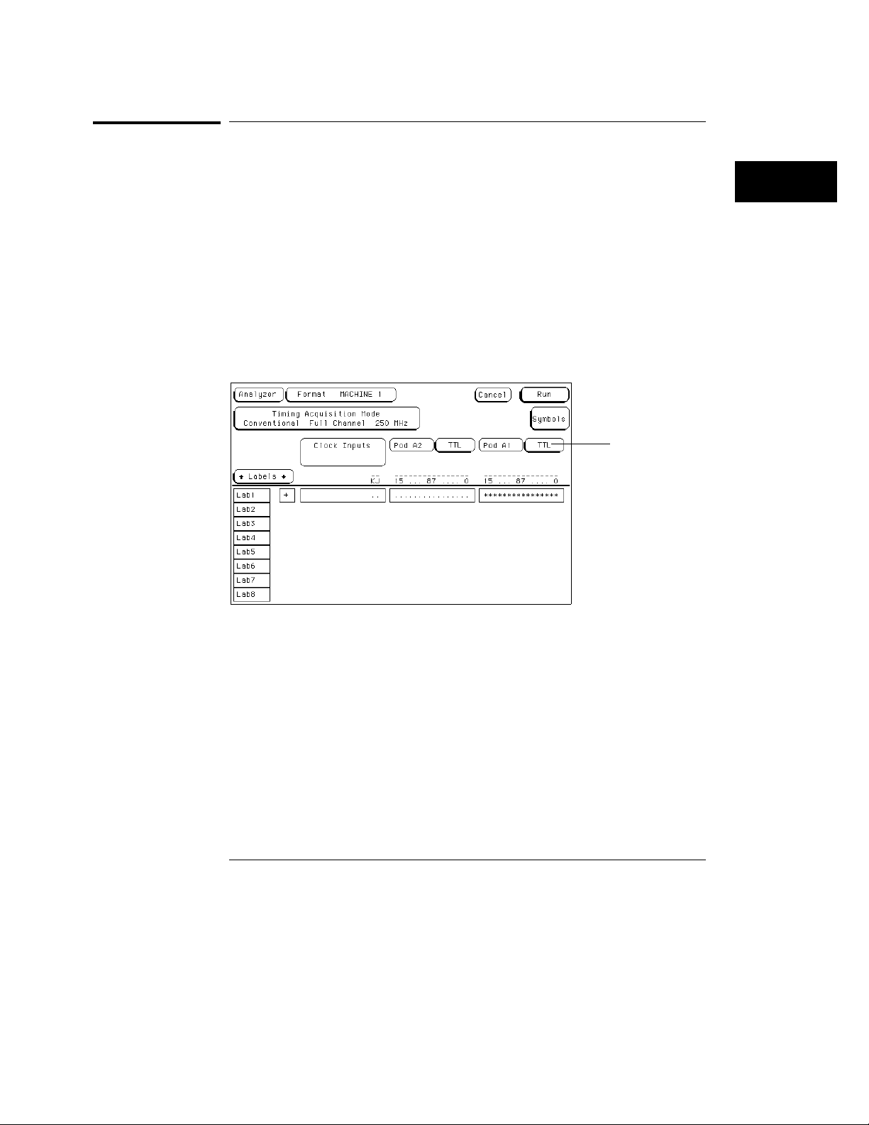
An example of a numeric entry menu in which you enter both the value and
the units is the pod threshold pop-up menu.
Press the analyzer Format MENU key.
1
2 Press the arrow keys to highlight the pod threshold field as shown
below, then press the
Select key.
Pod threshold field
Pod Threshold Field
3–19
Page 55
Using the Front-Panel Interface
How to Enter Numeric Data
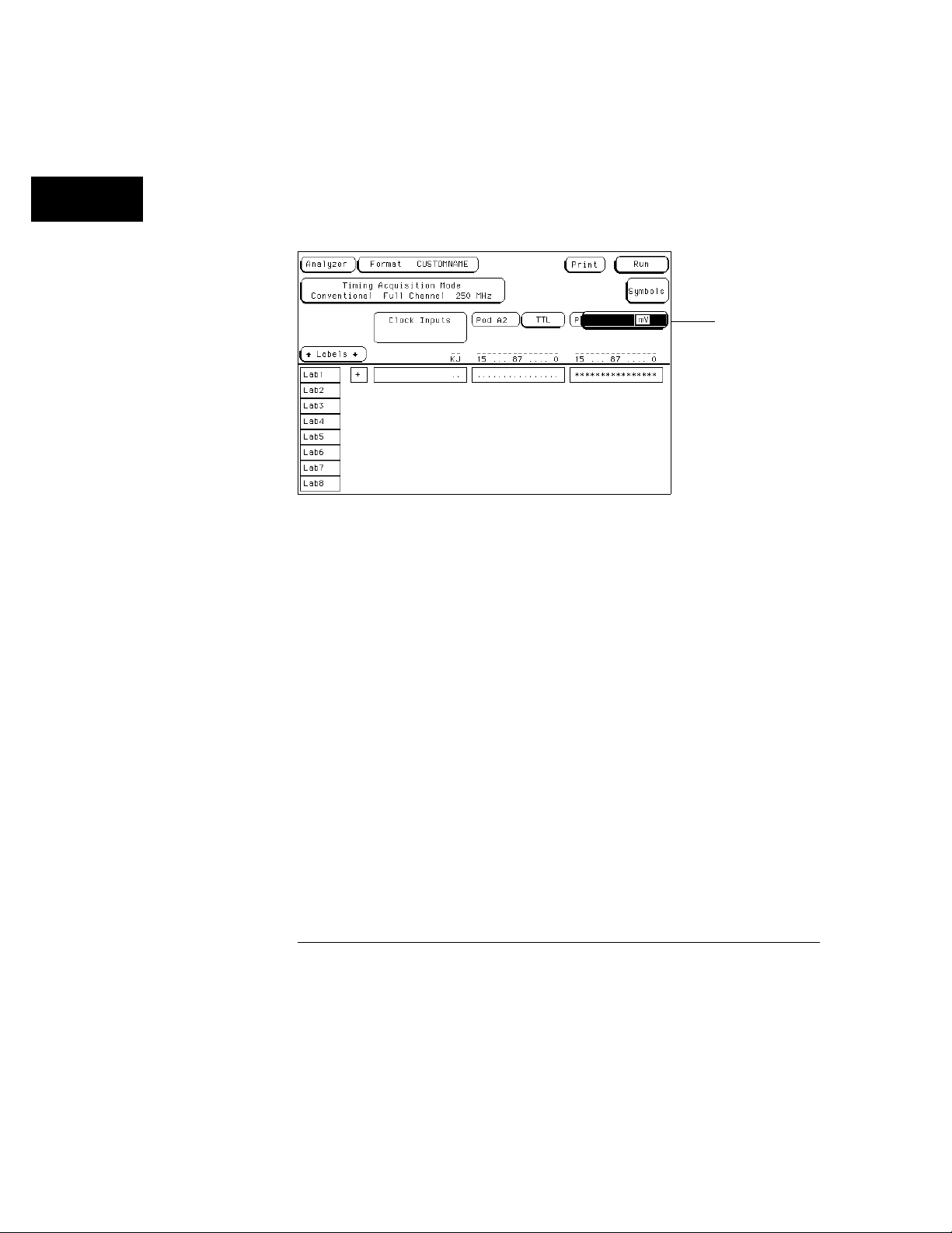
3 Press the Up/Down arrow keys or turn the knob to highlight the User
field, then press the
4 Press the arrow keys or turn the knob to set the units assignment field
Select key.
to V or mV as shown below.
Units assignment
Units Assignment field
5 Enter a value using the Hex keypad. If you want a negative threshold
voltage, press the ± key on the front panel.
6 To close the numeric assignment field, press the Select or Done keys.
3–20
Page 56
Using the Front-Panel Interface
How to Enter Alpha Data
How to Enter Alpha Data
You can customize your analyzer configuration by giving names to several
items:
The name of each analyzer.
•
Labels.
•
Symbols.
•
Filenames.
•
File descriptions.
•
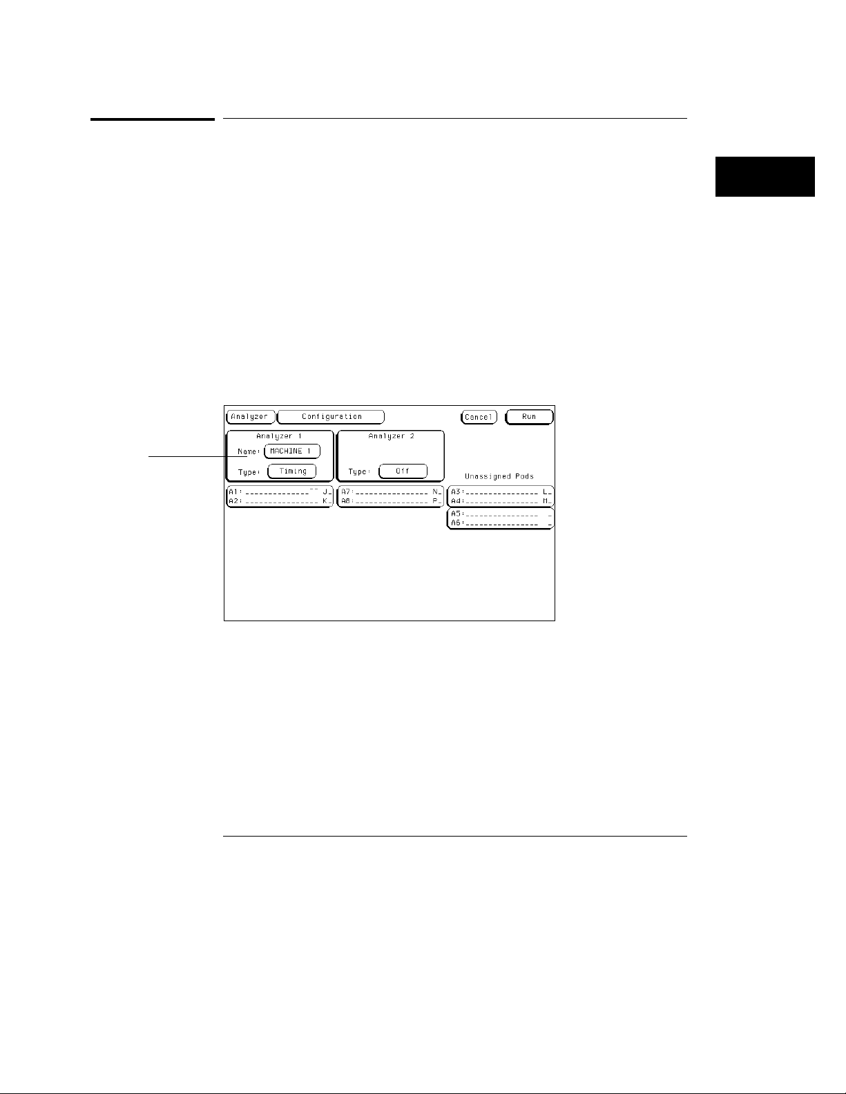
1 Press the analyzer Config MENU key.
2 Press the arrow keys to move the cursor to the Analyzer 1 "Name"
field as shown.
Analyzer 1
name field
Analyzer Name Field
3–21
Page 57
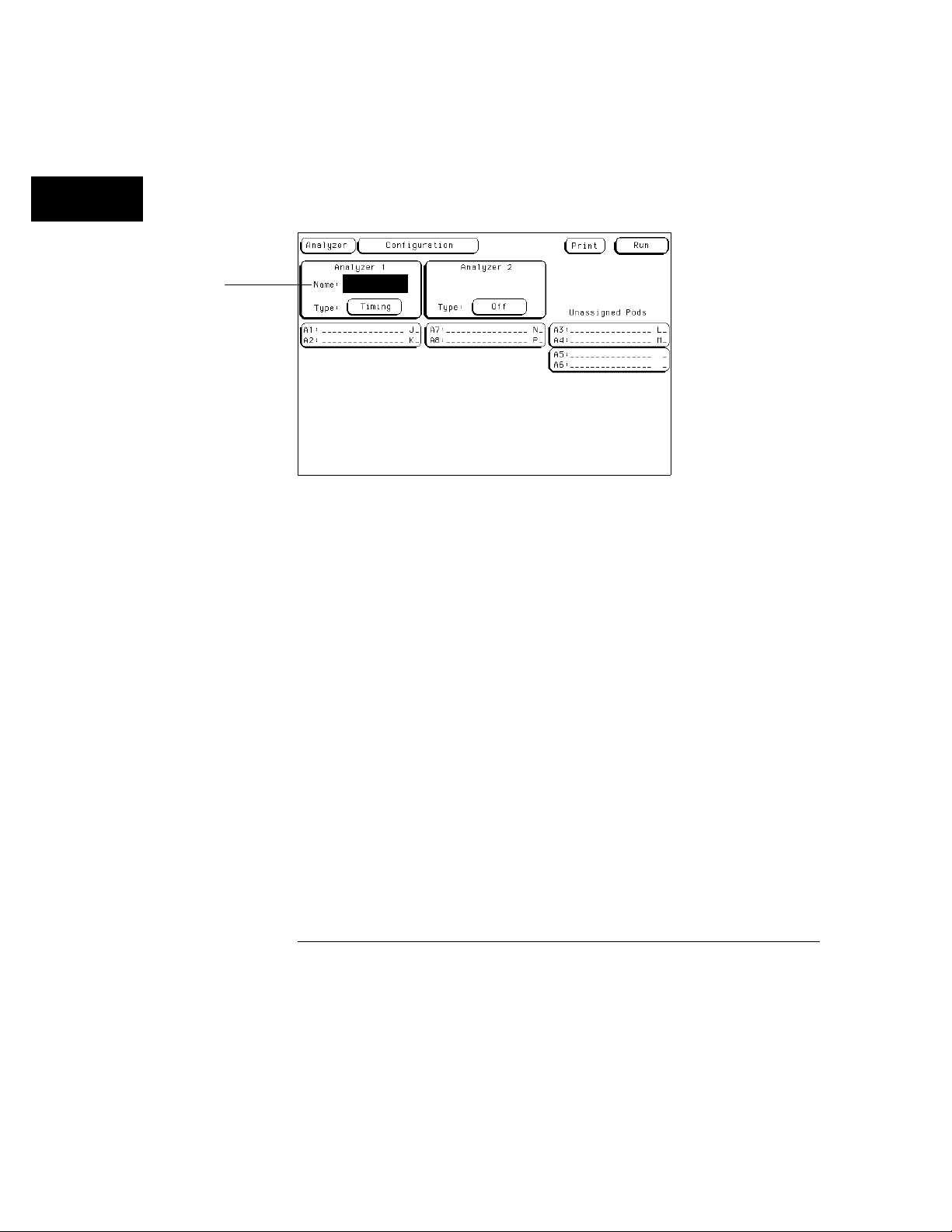
Name field
Using the Front-Panel Interface
How to Enter Alpha Data
3 Using the alpha keypad, enter a custom name as shown below.
A custom name can contain up to 10 letters. As you type the new name, the
old name is overwritten.
Alpha Entry
4 When you are finished entering a custom name, press the Done or
Select keys.
Changing Alpha Entries If you want to make changes or corrections
in the alpha entry field, use the arrow keys or the knob to position the
underscore marker under the character you want to change and type the
new letters. To quickly clear the Name field, you can press the Clear
entry key.
3–22
Page 58
Using the Front-Panel Interface
How to Roll Offscreen Data
How to Roll Offscreen Data
If there is offscreen data, it must be rolled back onscreen before it can be
viewed or acted upon. The types of data you typically find located offscreen
are Labels, Pods, Terms, Sequence Levels, and data listings. Each of the data
types have a roll field. These roll fields indicate offscreen data by becoming a
dark selectable field with small arrows showing the direction the data is
rolled. In addition, a roll indicator appears that indicates which rollable field
is currently active.
There are two ways to roll data. One is with the knob, the other is with the
Page keys. The following exercise demonstrates both ways by first having
you assign enough data to create offscreen data, then rolling the data.
Using the Knob
Press the analyzer Config MENU key.
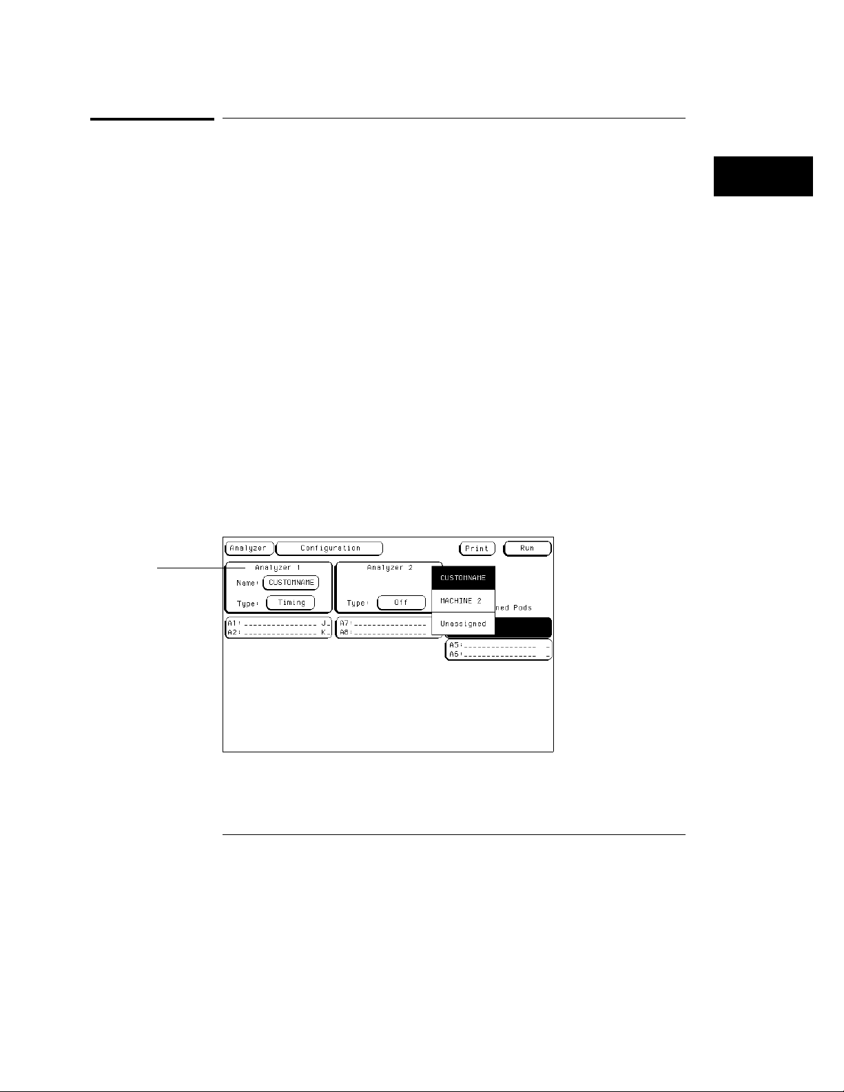
1
2 Press the arrow keys to move the cursor to the A3/A4 pod pair field in
the Unassigned Pods list, then press the
3 Press the Up/Down arrow keys or rotate the knob to move the cursor to
the custom name for Analyzer 1 as shown below, then press the
.
key
You should now have pod pairs A1/A2 and A3/A4 assigned to Analyzer 1.
Select key.
Select
Analyzer 1
Configuration menu
3–23
Page 59
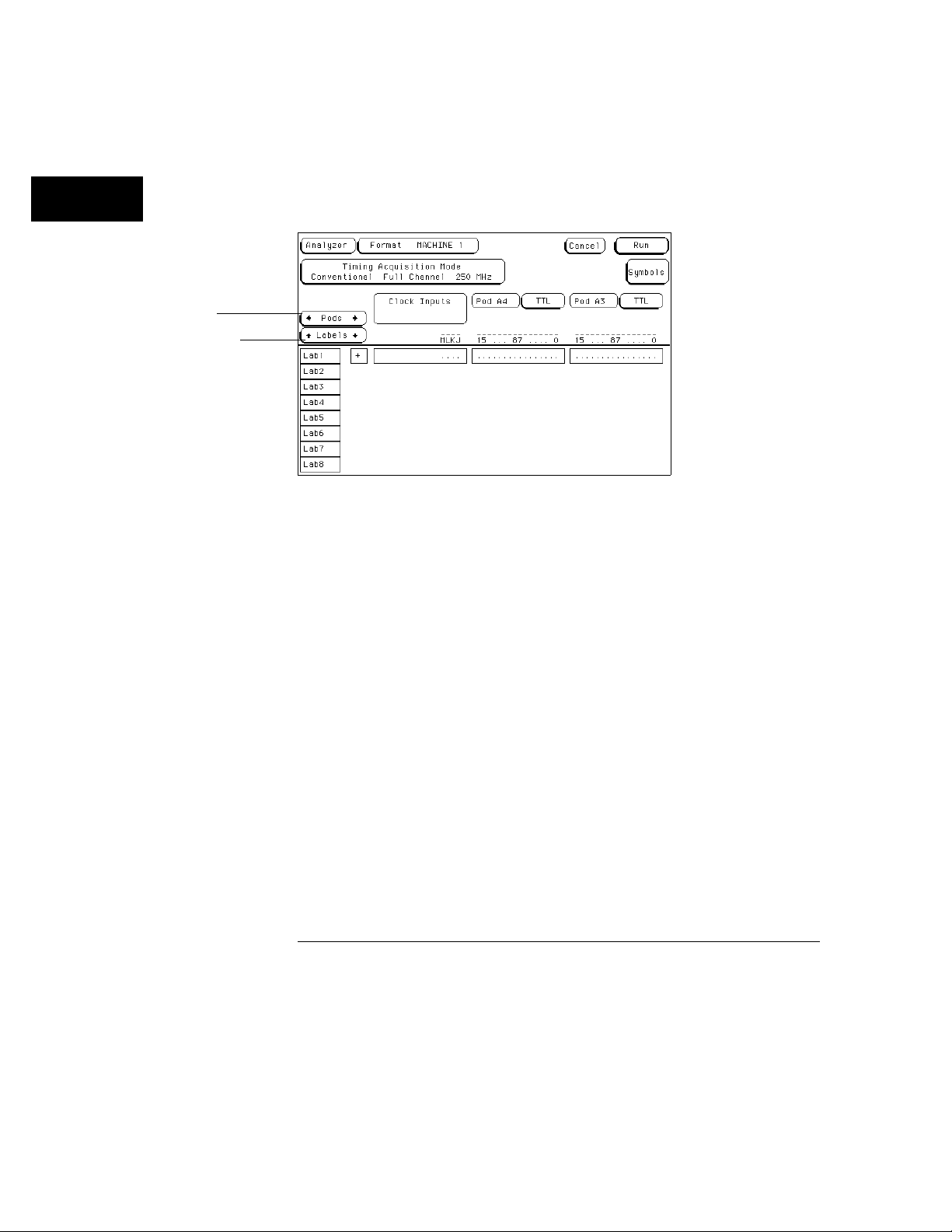
Pods roll field with roll
indicator
Labels roll field
Using the Front-Panel Interface
How to Roll Offscreen Data
4 Press the analyzer Format MENU key.
5 Notice the roll indicator in the Pods roll field as shown. Rotate the
knob and notice how pods A1 through A4 are rolled left and right.
Pods and Labels Roll Field
6 Press the Down arrow key to move the cursor to the Labels roll field
directly below the Pods roll field, then press the
Select key or just
turn the knob.
7 Notice the roll indicator now switches to the Labels roll field. Rotate
the knob and notice how the column of labels roll up and down.
Using the Page Keys
Press the Up/Down Page keys and notice how the column of labels page
8
up and down.
9 Press the Up arrow key to move the cursor back to the Pods roll field,
then press the
10 Press the blue shift key, then press a Page key.
The left and right page keys must be preceded by the blue shift key each
time. Repeat this two key sequence to page the Pods left and right.
Select key.
3–24
Page 60
Using the Front-Panel Interface
How to Use Assignment/Specification Menus
How to Use Assignment/Specification Menus
There are a number of assignment fields which you must assign or specify
what you want the instrument to do. Menus of this type are as follows:
Assigning pod channels and clock channels to labels.
•
Specifying patterns.
•
Specifying edges.
•
Assigning Pod and Clock Channels
The channel assignment fields in both state and timing analyzers appear in
the Format menus and work identically. It should be noted that if you don’t
see any channel assignment fields, it merely means you do not have any pods
assigned to this analyzer or any labels turned on. The convention for channel
assignments is as follows:
* (asterisk) indicates assigned channels
. (period) indicates un-assigned channels
To assign channels to an analyzer, do the following exercise:
1 Press the analyzer Format MENU key.
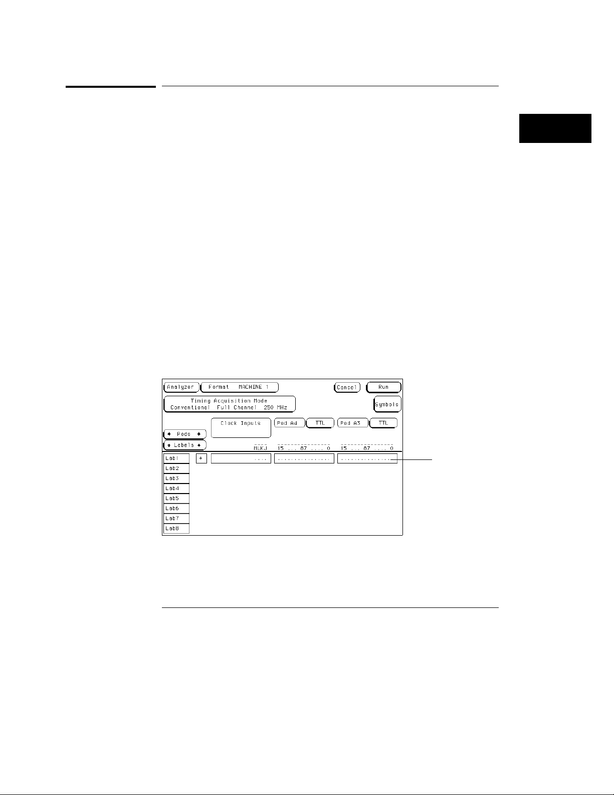
2 Press the arrow keys to move the cursor to the channel assignment
field as shown below, then press the
Select key.
Channel Assignment Field
Channel assignment
3–25
Page 61
Using the Front-Panel Interface
How to Use Assignment/Specification Menus
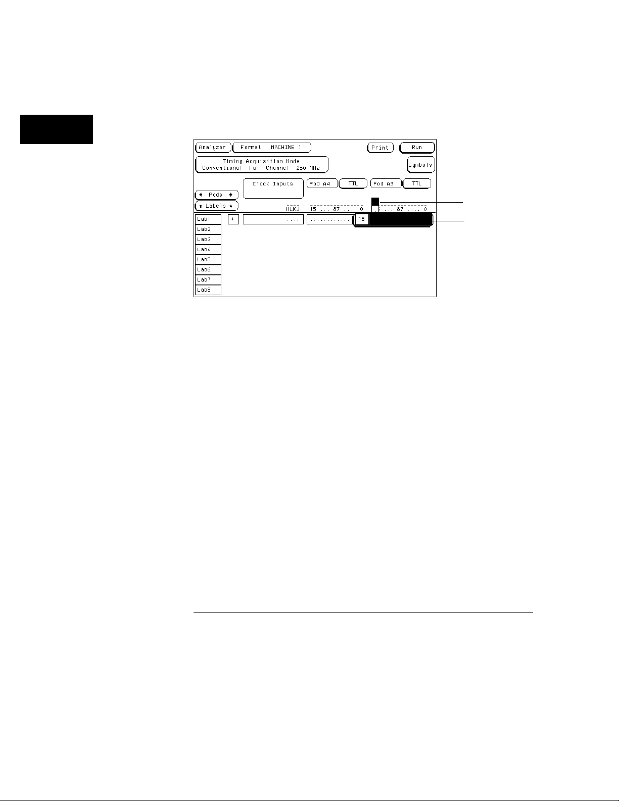
When the channel assignment field is selected, an assignment pop-up
appears showing you the bit or channel to be assigned, and the two choices
directly above it.
Assignment choices
Assignment pop-up
Channel Assignment Pop-up
3 Turn all channels on (assign an asterisk) by either pressing the Select
key or by pressing the Up arrow key.
Individual bits or channels are highlighted by moving the cursor side to side
with the left/right arrow keys or by rotating the knob. The Select key toggles
the current choice. The up arrow assigns a channel, and the down arrow
unassigns a channel. In addition, the entire bank of channels are assigned or
cleared by pressing the Clear entry key.
When you are finished assigning channels, press the Done key.
4
3–26
Page 62

Using the Front-Panel Interface
How to Use Assignment/Specification Menus
Specifying Patterns
Certain assignment fields require bit patterns to be specified. Patterns can
be specified in any one of the available number bases, except ASCII. A
pattern can contain a value or a "Don’t care."
The convention for "Don’t cares" in these menus is an "X" except in the
decimal base. If the base is set to decimal after a "don’t care" is specified, a $
character is displayed.
To specify a pattern, perform the following exercise:
Press the analyzer Trigger MENU key.
1
2 Press the arrow keys to move the cursor to the assignment field for
the "a" resource term as shown.
Resource term "a"
assignment field
Resource Term Assignment Field
3 Using the Hexadecimal keypad, enter a pattern, then press the Select
key.
In addition to using the numeric keypad, you can enter "Don’t cares" into the
entire assignment field by pressing the Clear entry key.
3–27
Page 63
Using the Front-Panel Interface
How to Use Assignment/Specification Menus
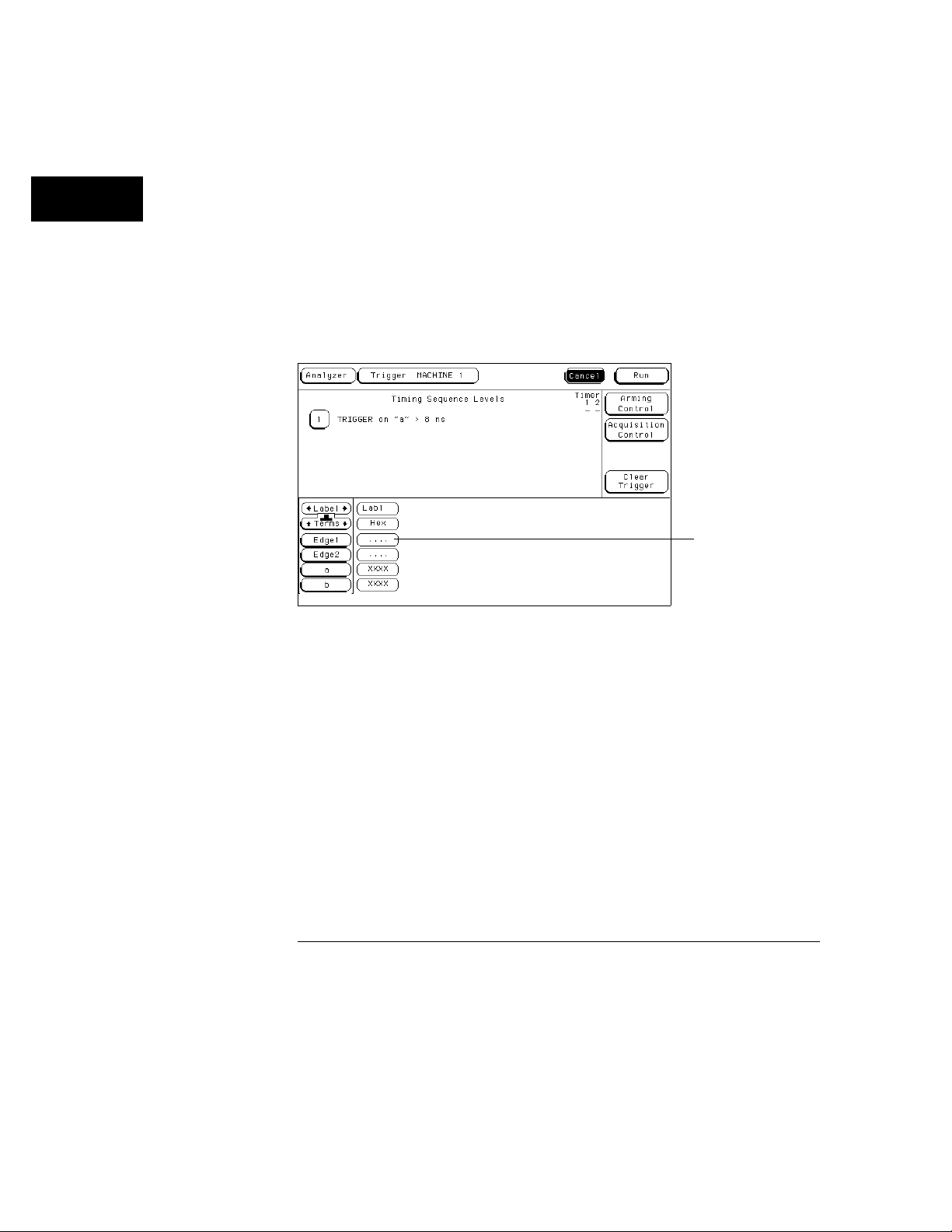
Specifying Edges
Certain assignment fields require edge assignments to be specified. An edge
can be specified in any one of the available number bases.
You can select positive-going ( ↑ ), negative-going ( ↓ ), either edge ( ↕ ) or
no edge (
To specify an edge, perform the following exercise:
Press the analyzer Trigger MENU key.
1
2 Press the arrow keys to move the cursor to the Edge 1 assignment
field as shown, then press the
. ).
Select key.
Edge and Glitch Assignment Field
3–28
Edge assignment
field
Page 64
Using the Front-Panel Interface
How to Use Assignment/Specification Menus
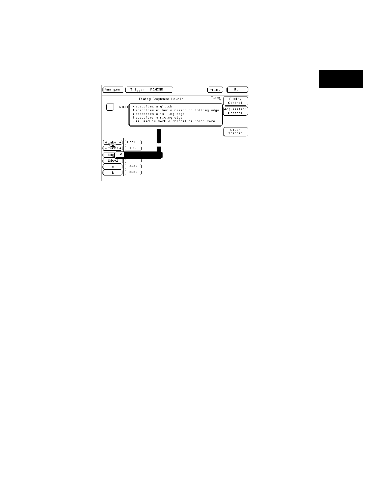
When the Edge and Glitch assignment field is selected, an assignment pop-up
appears showing you the bit or channel to be assigned, and the five choices
directly above it.
Edge and glitch
selection list
Edge and Glitch Selection List
3 Press the Up/Down arrow keys to move the cursor to the desired edge
assignment, then press the
left/right arrow key or turn the knob to move
the cursor to the next channel. Repeat step 3 until all of the desired
channels are assigned.
4 To close the assignment field, press the Done key.
Individual bits or channels are cleared by pressing the front-panel (.) period
key. The entire bank of channels are cleared by pressing the Clear entry key.
It should be noted that when you close the pop-up after specifying edges, you
see dollar signs ($ $ ... ) in the assignment field. This simply indicates the
logic analyzer can’t display the assignment correctly in the current number
base selected.
3–29
Page 65

3–30
Page 66

4
Using the Mouse and the Optional Keyboard
Page 67

The Mouse and the Optional Keyboard
This chapter explains how to use the mouse and the optional
keyboard interface (Agilent Technologies E2427A Keyboard Kit). The
keyboard and mouse can be used interchangeably with the knob and
front-panel keypad for all menu applications. The keyboard and
mouse functions fall into the two basic categories of cursor movement
and data entry.
Both the keyboard or mouse can be connected to the keyboard/mouse
connector on the rear panel of the logic analyzer. If both are
connected at the same time, the keyboard is connected to the
analyzer and the mouse is connected to the keyboard.
When the keyboard and/or mouse is connected, a graphic is included
in the RS-232 / GPIB (or Printer/Controller) menu to represent the
interface options being used.
See Also The documentation that comes with each interface device for complete
details on connecting them to each other or, to the logic analyzer.
4–2
Page 68

Using the Mouse and the Optional Keyboard
Moving the Cursor
Moving the Cursor
The keyboard cursor is the location on the screen highlighted in inverse
video. To move the cursor, follow one of the methods described below.
Keyboard Cursor Movement
There are four cursor keys marked with arrows on the keyboard. These keys
perform the following movements:
Up-pointing arrow moves the cursor up.
•
Down-pointing arrow moves the cursor down.
•
Right-pointing arrow moves the cursor to the right.
•
Left-pointing arrow moves the cursor to the left.
•
The cursor keys do not wrap. This means that pressing the right-pointing
arrow when the cursor is already at the rightmost point in a menu will have
no effect. The cursor keys do repeat, so holding the key down is the fastest
way to continue keyboard cursor movement in a given direction.
Home Key (or corner arrow) If you want to move the cursor to the
first item in a menu, press the Home key. If you want to move the cursor
to the last item in a menu, press the Home and Shift keys simultaneously.
Next and Previous Keys The Next and Previous keys are used for
paging through listings. The Next key will display the next page of data,
if one exists. The Previous key will display the previous page of data, if
one exists.
Selecting a Menu Item
To select a menu item using the optional keyboard, position the cursor (the
location highlighted in inverse video) on the desired menu item using one of
the methods described in the section “Moving the Cursor” and press either
the Return or the Select key.
4–3
Page 69

Using the Mouse and the Optional Keyboard
Entering Data into a Menu
Mouse Cursor Movement
The mouse pointer (+) is positioned around the screen by moving the mouse
about on top of a desktop or other even surface.
Selecting a Menu Item To select a menu field, simply move the
pointer on top of the desired field and press the upper-left button.
To duplicate the front-panel knob, hold down the upper-right button while
moving the mouse around the desktop. Moving the mouse up or to the right
duplicates turning the knob clockwise. Moving the mouse down or to the left
duplicates turning the knob counterclockwise.
Entering Data into a Menu
Keyboard Data Entry
When an assignment field is selected, the cursor is displayed under the
leftmost digit in the particular field. When you type in a number or letter, it is
displayed in the cursor position, and the cursor is advanced. Cursor keys
move the cursor within the assignment field. Pressing either the Return key
or the Enter key will terminate data entry for that item.
If you want to erase the data entry, press the Clear Line key, the Clear
Display key, or the Delete Line key.
Mouse Data Entry
When an assignment field is selected, a pop-up keypad or assignment menu
appears. Use the pop-up menus to assign letters, numbers, symbols, or unit
of measure. When the Done field is selected, the pop-up closes and the
selected values are entered into the assignment field.
4–4
Page 70
Using the Mouse and the Optional Keyboard
Using the Keyboard Overlays
Using the Keyboard Overlays
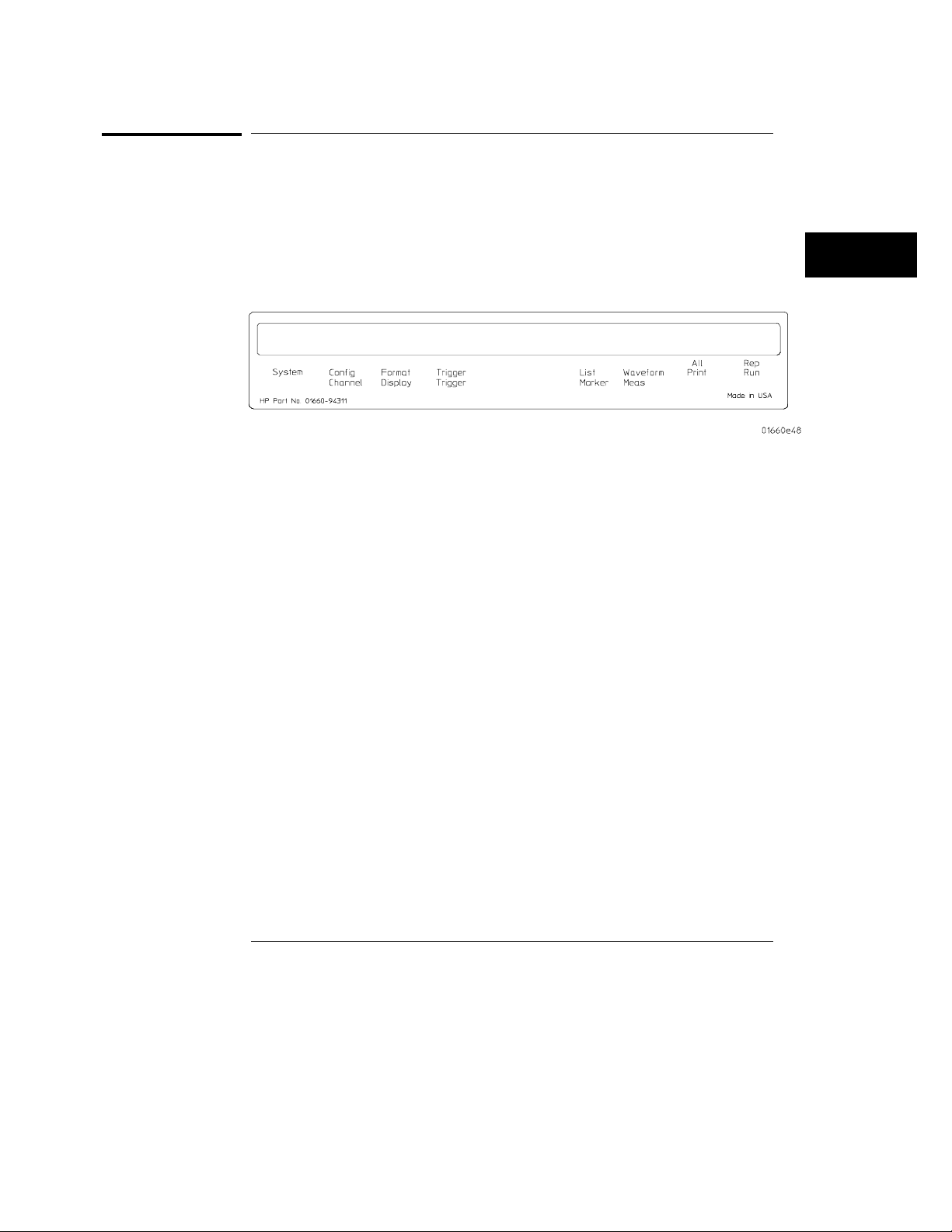
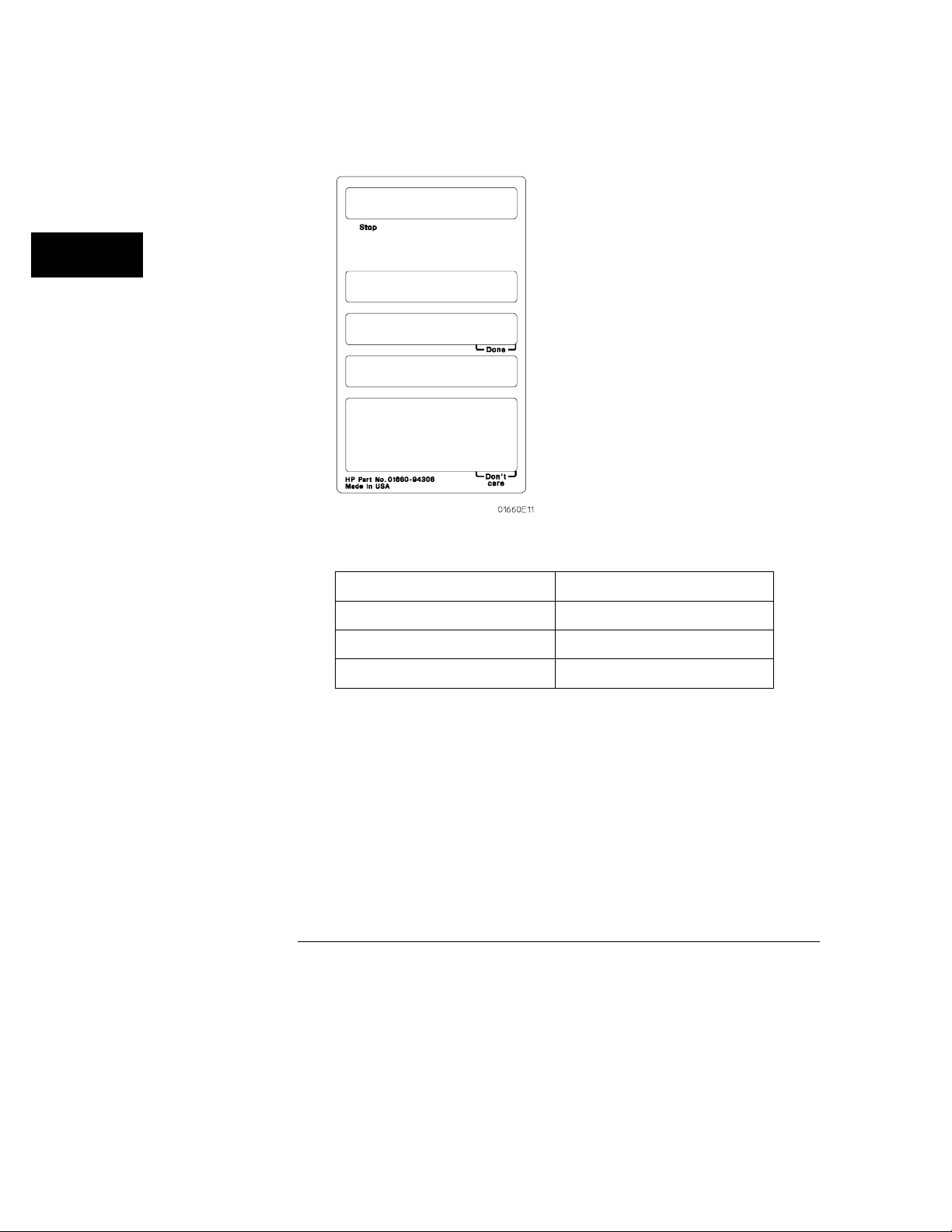
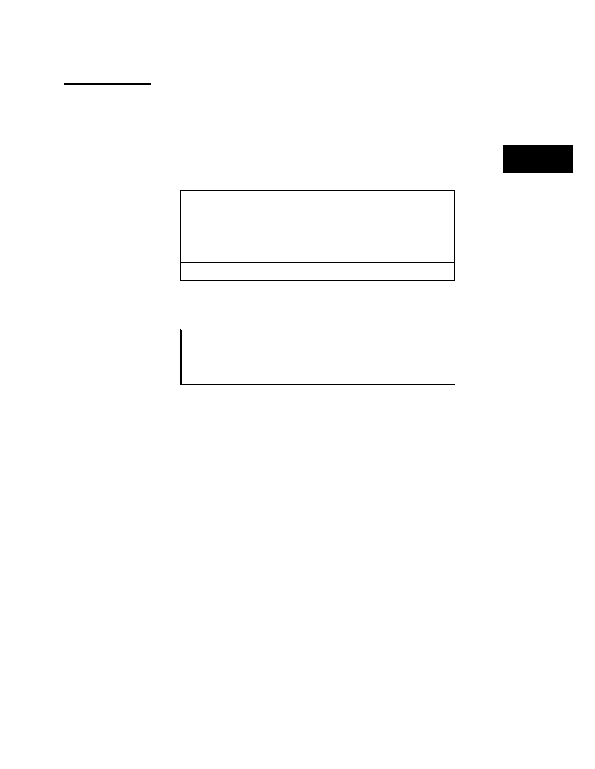
Two keyboard overlays are included in the E2427A Keyboard Kit. The
overlays shown below redefine functions of the function keys and the
numeric keypad.
Function Key Overlay
Key Function Performed
F1 Selects System subset menus
F2 Selects the Analyzer Configuration Menu (ignore Scope Channel Menu)
F3 Selects the Analyzer Format Menu (ignore Scope Display Menu)
F4 Selects the Analyzer Trigger Menu (ignore Scope Trigger Menu)
F5 Selects the Analyzer Listing Menu (ignore Scope Marker Menu)
F6 Selects the Analyzer Waveform Menu (ignore Scope Auto-Measure Menu)
F7 Selects the Print All function
F8 Selects the Run Repetitive function
4–5
Page 71
Using the Mouse and the Optional Keyboard
Using the Keyboard Overlays
Numeric Keypad Overlay
Key Function Performed
Tab Don’t care "X"
Enter Done
Stop (unlabeled) Stop
4–6
Page 72
Using the Mouse and the Optional Keyboard
Defining Units of Measure
Defining Units of Measure
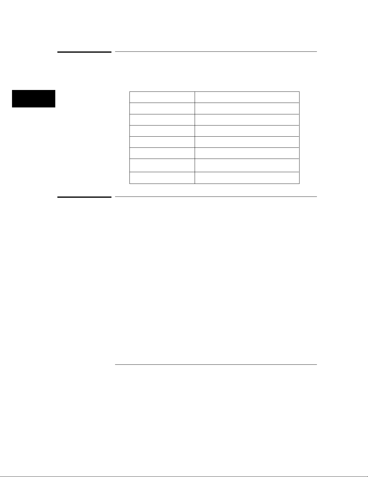
In addition to the function keys, other keys on the keyboard invoke the unit
of measure selections.
Time Units
Key Time Units
S Selects the seconds units
M Selects the milliseconds units
U Selects the microseconds units
N Selects the nanoseconds units
Voltage Units
Key Voltage Units
V Selects volts
M Selects millivolts
4–7
Page 73
Using the Mouse and the Optional Keyboard
Assigning Edge Triggers
Assigning Edge Triggers
Several keys invoke edge assignments.
Key Edge Trigger Assignment
U Selects the up or rising edge.
D Selects the down or falling edge.
R Selects the rising edge.
F Selects the falling edge.
B Selects either the rising or falling edge.
∗ (asterisk)
. (period)
Assigns a glitch.
Assigns a Don’t Care
Closing a Menu
To exit a menu, press either the Done or Enter key. The Enter key is
mapped to the Done key, so pressing either key closes the menu.
4–8
Page 74
5
Connecting a Printer
Page 75

Connecting a Printer
The logic analyzer can output its screen display to various GPIB,
RS-232C, and Centronix graphics printers (1664A only). Configured
menus as well as waveforms, listings and other data, can be printed
for complete measurement documentation.
5–2
Page 76
Connecting a Printer
GPIB Printers
GPIB Printers
The logic analyzer interfaces directly with HP PCL printers supporting the
printer command language or with Epson printers supporting the Epson
standard command set. These printers must also support GPIB and Listen
Always. Printers currently available from Hewlett-Packard with these
features include:
HP ThinkJet
•
HP LaserJet
•
HP PaintJet
•
HP DeskJet
•
HP QuietJet
•
It should be noted that an GPIB printer must always be in Listen mode, and
the analyzer’s GPIB port does not respond to service requests (SRQ) when
controlling a printer. The SRQ enable setting for the GPIB printer has no
effect on 16600B printer operation.
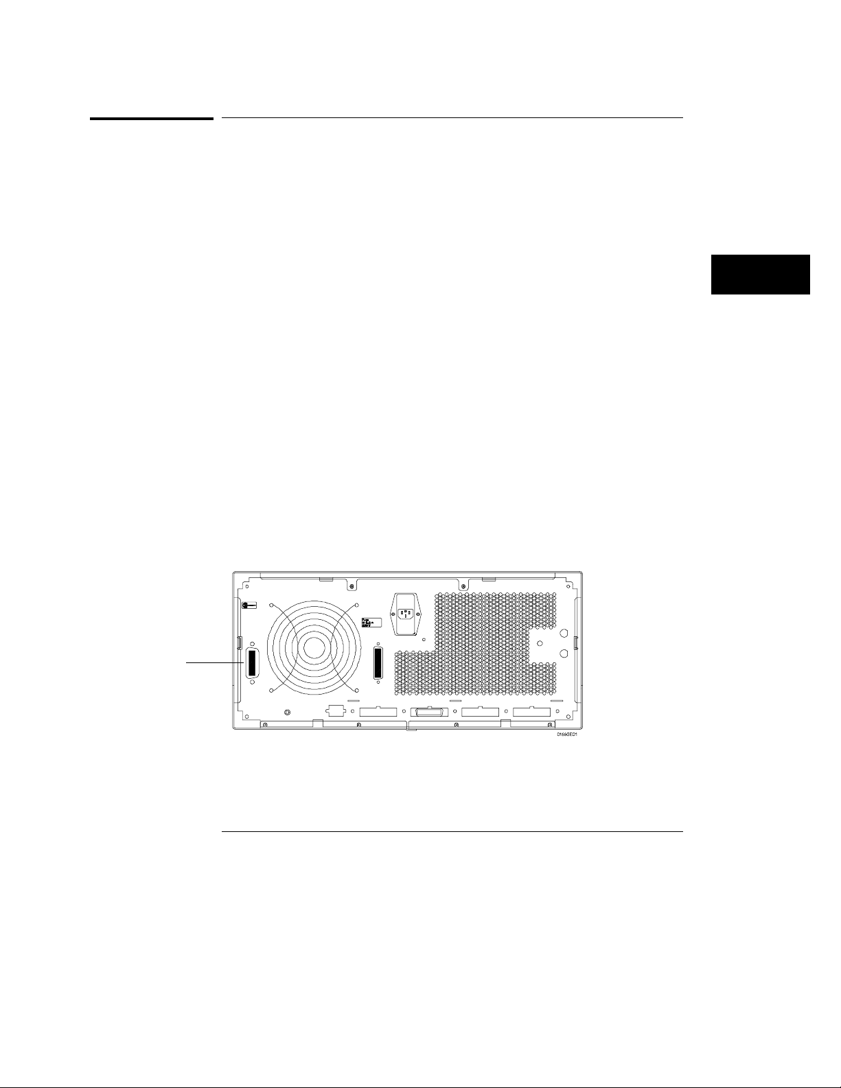
GPIB Connector
(location different
for 1664A)
GPIB Printer Setup
To set up the GPIB printer, perform the following steps:
Turn off the instrument and connect an GPIB cable from the printer
1
to the GPIB connector on the rear panel of the instrument. Turn on
the instrument.
GPIB Connector
5–3
Page 77
Connecting a Printer
GPIB Printers
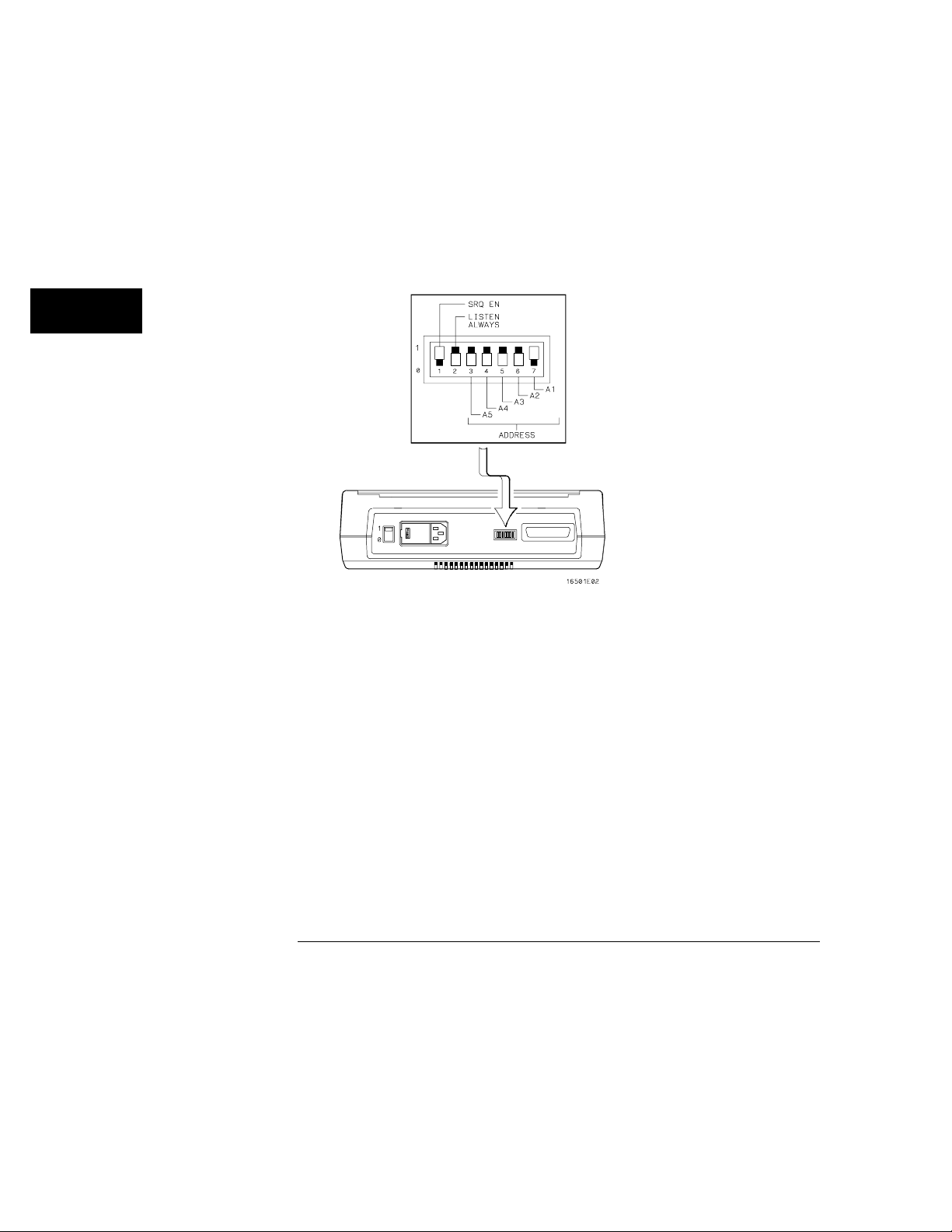
2 Make sure the printer is in Listen Always (or Listen Only). For
example, the figure below shows the GPIB configuration switches for
an GPIB ThinkJet printer. For the Listen Always mode, move the
second switch from the left to the “1" position.
Since the instrument doesn’t respond to SRQ EN (Service Request Enable),
the position of the first switch doesn’t matter.
Listen Always Switch Setting
5–4
Page 78
Connecting a Printer
GPIB Printers
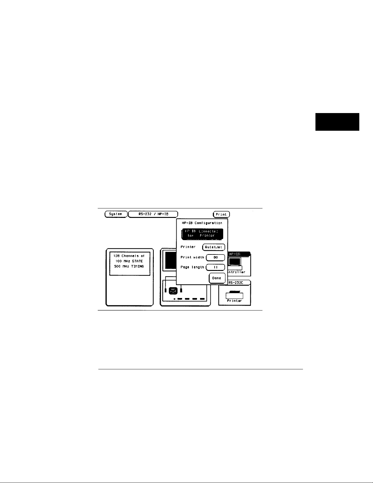
GPIB Configuration (1660A through 1663A)
From the RS-232 / GPIB menu, perform the following steps to configure the
GPIB interface for printing:
Select the GPIB field.
1
2 When the pop-up appears, select "GPIB Connected to" field, and
toggle to the
3 Select the field to the right of “Printer” and when the pop-up appears,
Printer selection.
select the printer that you’re using (like, ThinkJet or QuietJet). If
you’re using an Epson graphics printer or an Epson-compatible
printer, select
See Also "RS-232 / GPIB Interface" chapter for more information on selecting the GPIB
Address to match the setup for the GPIB printer.
Select the "Print Width" field. The print width toggles between 80 and
4
132. Select the width for your application or leave it at the default of
Alternate.
80.
Print width tells the printer that you are sending up to 80 or 132 characters
per line (when you Print All) and is totally independent of the printer itself.
GPIB Configuration Menu (1660A through 1663A)
5–5
Page 79

Connecting a Printer
GPIB Printers
If you select 132 characters per line when using other than the QuietJet
selection, the listings are printed in a compressed mode. Compressed mode
uses smaller characters to allow the printer to print more characters within a
given area.
If you select 132 characters per line for the QuietJet selection it can print a
full 132 characters per line without going to compressed mode, but the
printer must have wider paper.
If you select 80 characters per line for any printer, a maximum of 80
characters are printed per line.
Select the "Print Length" field. The print length toggles between 11
5
and 12. Select the length for your application or leave it at the default
11.
of
Print length tells the printer the page length for the type of paper you are
using.
Press the front-panel Done key.
6
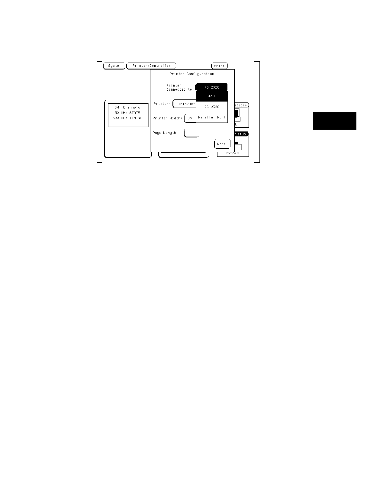
Optional GPIB Configuration (1664A)
From the Printer/Controller menu, perform the following steps to configure
the GPIB interface for printing:
Select the Printer Setup field.
1
2 When the pop-up appears, select "Printer Connected to GPIB" field,
and toggle to the
3 Select the field to the right of “Printer” and when the pop-up appears,
Printer selection.
select the printer that you’re using (like, ThinkJet or QuietJet). If
you’re using an Epson graphics printer or an Epson-compatible
printer, select
Alternate.
See Also "RS-232 / GPIB Interface" chapter for more information on selecting the GPIB
Address to match the setup for the GPIB printer.
Select the "Print Width" field. The print width toggles between 80 and
4
132. Select the width for your application or leave it at the default of
80.
Print width tells the printer that you are sending up to 80 or 132 characters
per line (when you Print All) and is totally independent of the printer itself.
If you select 132 characters per line when using other than the QuietJet
selection, the listings are printed in a compressed mode. Compressed mode
uses smaller characters to allow the printer to print more characters within a
given area.
5–6
Page 80
Connecting a Printer
GPIB Printers
GPIB Configuration Menu (1664A)
If you select 132 characters per line for the QuietJet selection it can print a
full 132 characters per line without going to compressed mode, but the
printer must have wider paper.
If you select 80 characters per line for any printer, a maximum of 80
characters are printed per line.
5–7
Page 81
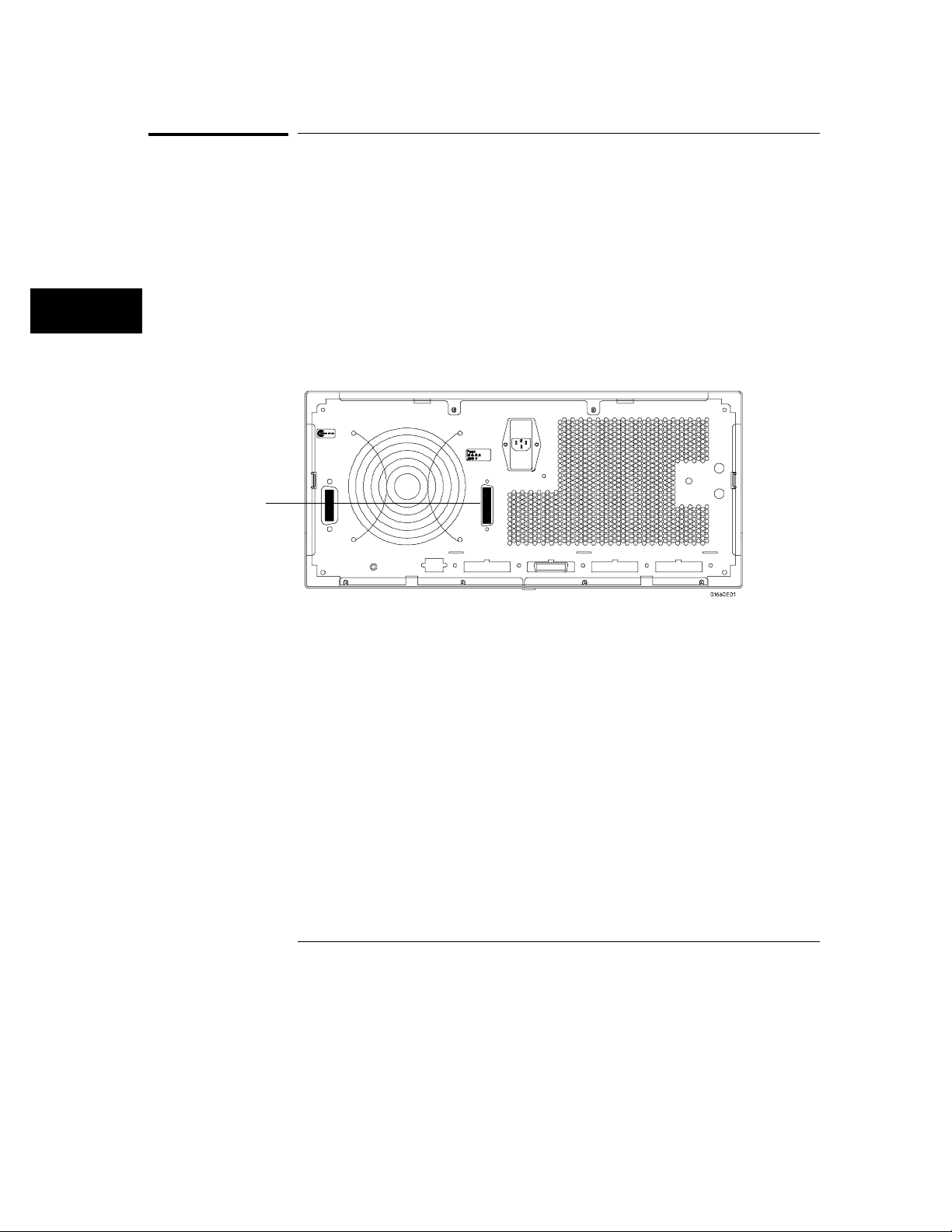
Connecting a Printer
RS-232C Printers
RS-232C Printers
The instrument interfaces directly with RS-232C printers including the HP
ThinkJet, HP QuietJet, HP LaserJet, HP PaintJet, and HP DeskJet printers.
RS-232C Printer Setup
To set up the RS-232C printer, perform the following steps:
Turn off the instrument and connect an RS-232C cable from the
1
printer to the RS-232C connector on the rear panel of the instrument.
Turn on the instrument.
RS-232C connector
(location different
on 1664A)
RS-232C Connector
5–8
Page 82
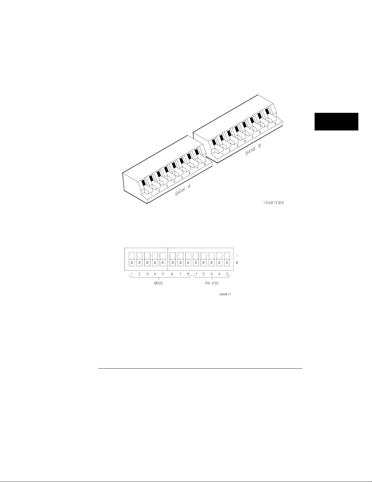
Connecting a Printer
RS-232C Printers
2 Before turning on the printer, locate the mode configuration switches
on the printer and configure them as follows:
The HP QuietJet series printers have two banks of mode function switches
•
inside the front cover. Push all the switches down to the “0" position as
shown.
For the HP 2225D (RS-232 HP ThinkJet) printer, the mode switches are
•
on the rear panel of the printer. Push all the switches down to the “0"
position as shown .
For the HP LaserJet printer, the switch settings can remain in the factory
•
default settings.
5–9
Page 83
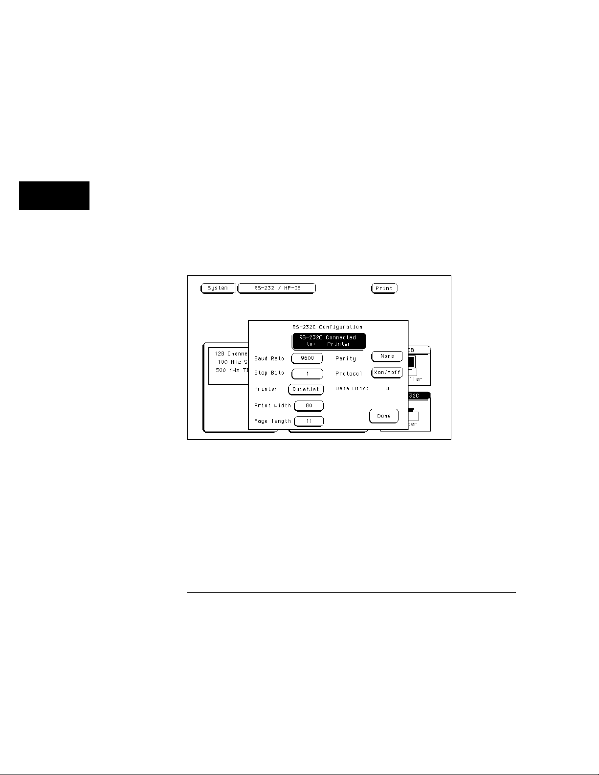
Connecting a Printer
RS-232C Printers
RS-232C Configuration (1660A through 1663A)
From the RS-232 / GPIB menu, perform the following steps to configure the
RS-232 interface for printing:
Select the RS-232 field.
1
2 When the pop-up appears, select "RS-232 Connected to" field, and
toggle to the
3 Set the baud rate, stop bits, parity, and protocol to match the setup
Printer selection as shown below.
for the RS-232C printer by selecting the appropriate fields.
4 Select the field to the right of “Printer” and when the pop-up appears,
select the printer that you’re using (like, ThinkJet or QuietJet). If
you’re using an Epson graphics printer or an Epson-compatible
printer, select
See Also "RS-232 / GPIB Interface" chapter for more information.
Alternate.
RS-232 Configuration Menu (1660A through 1663A)
5–10
Page 84
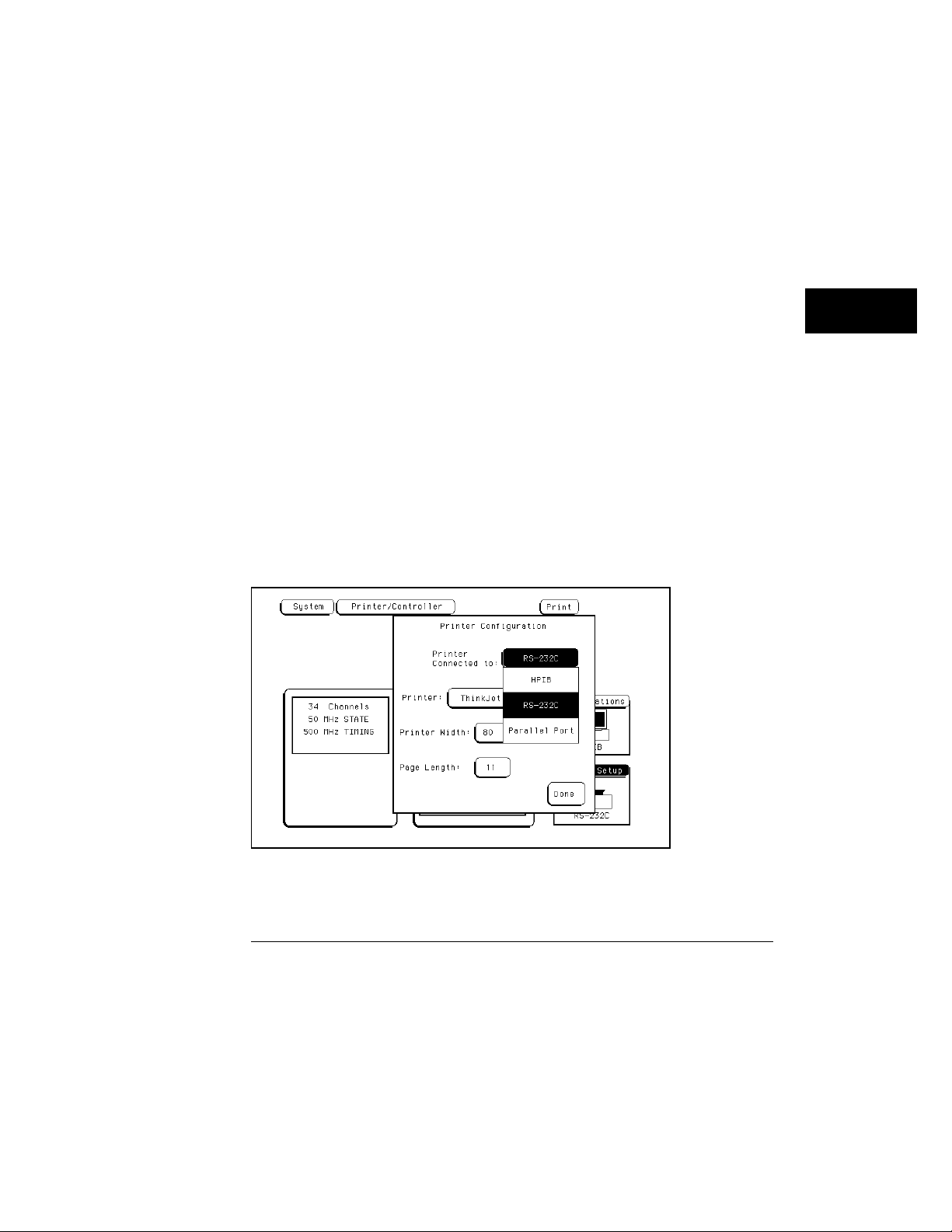
Connecting a Printer
RS-232C Printers
5 Select the "Print Width" field. The print width toggles between 80 and
132. Select the width for your application or leave it at the default of
80.
Print width tells the printer that you are sending up to 80 or 132 characters
per line (when you Print All) and is totally independent of the printer itself.
Touch the" Print Length" field and print length toggles between 11 and
6
12. Select the length for your application or leave it at the default of
11.
Print length tells the printer the page length for the type of paper you are
using.
Press the front-panel Done key.
7
Optional RS-232C Configuration (1664A)
From the Printer/Controller menu, perform the following steps to configure
the RS-232 interface for printing:
Select the Printer Setup field.
1
2 When the pop-up appears, select "Printer Connected to RS-232" field,
and toggle to the
3 Select the field to the right of “Printer” and when the pop-up appears,
Printer selection as shown below.
select the printer that you’re using (like, ThinkJet or QuietJet). If
you’re using an Epson graphics printer or an Epson-compatible
printer, select
Alternate.
RS-232 Configuration Menu (1664A)
5–11
Page 85

Connecting a Printer
RS-232C Printers
See Also "RS-232 / GPIB Interface" chapter for more information on selecting the baud
rate, stop bits, parity, and protocol to match the setup for the RS-232C
printer.
Select the "Print Width" field. The print width toggles between 80 and
4
132. Select the width for your application or leave it at the default of
80.
Print width tells the printer that you are sending up to 80 or 132 characters
per line (when you Print All) and is totally independent of the printer itself.
Touch the" Print Length" field and print length toggles between 11 and
5
12. Select the length for your application or leave it at the default of
11.
Print length tells the printer the page length for the type of paper you are
using.
Press the front-panel Done key.
6
5–12
Page 86
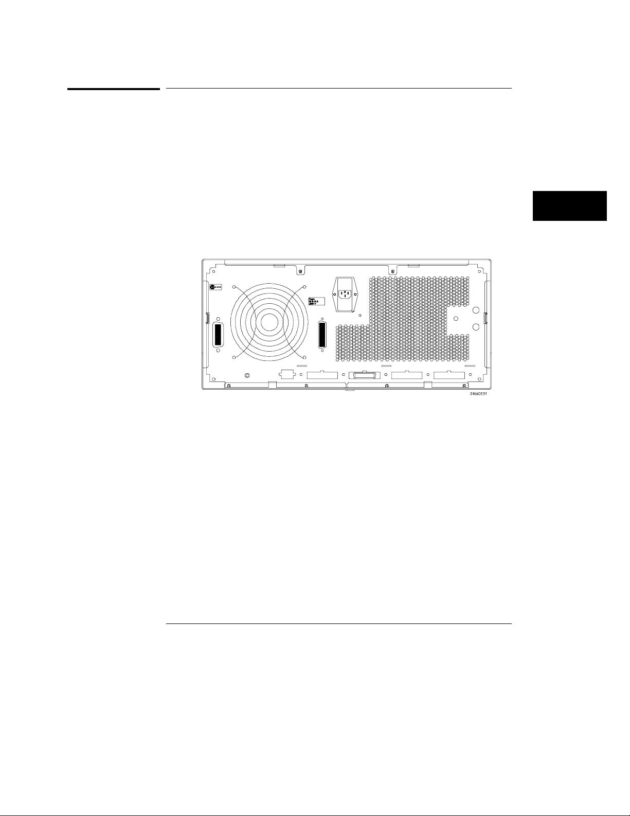
Connecting a Printer
Parallel Printers (1664A Only)
Parallel Printers (1664A Only)
The 1664A interfaces directly with Centronix (parallel) printers including the
HP ThinkJet, HP QuietJet, HP LaserJet, HP PaintJet, and HP DeskJet
printers.
Parallel Printer Setup
To set up the parallel printer, perform the following steps:
Turn off the instrument and connect a parallel cable from the printer
1
to the parallel printer port connector on the rear panel of the
instrument. Turn on the instrument.
Parallel Printer Port
connector
2 Before turning on the printer, configure the printer (switches/menu)
1
Parallel Printer Port Connector
for parallel operation. Information for parallel operation is located in
the User’s Guide provided with the printer.
Parallel Configuration
From the Printer/Controller menu, perform the following steps to configure
the Parallel interface for printing:
Select the Printer Setup field.
5–13
Page 87
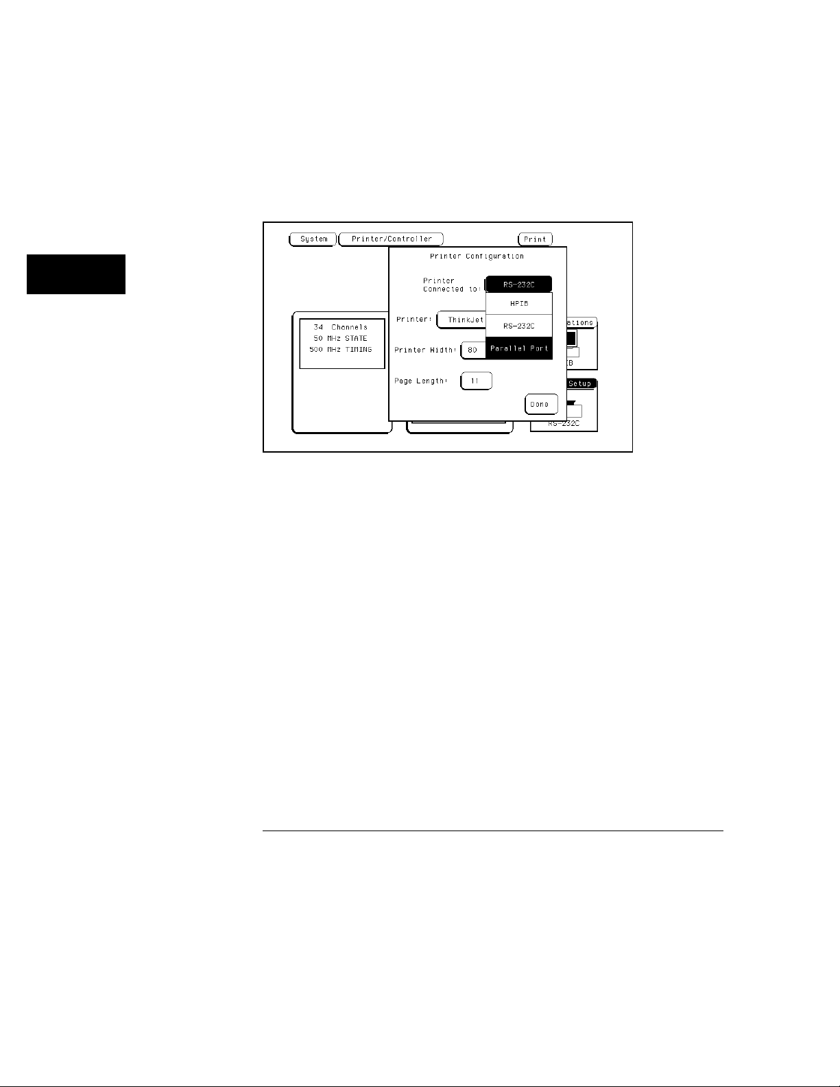
Connecting a Printer
Parallel Printers (1664A Only)
2 When the pop-up appears, select "Printer Connected to Parallel Port"
field, and toggle to the
3 Select the field to the right of “Printer” and when the pop-up appears,
Printer selection as shown below.
select the printer that you’re using (like, ThinkJet or QuietJet). If
you’re using an Epson graphics printer or an Epson-compatible
printer, select
Alternate.
Parallel Port Configuration Menu
4 Select the "Print Width" field. The print width toggles between 80 and
132. Select the width for your application or leave it at the default of
80.
Print width tells the printer that you are sending up to 80 or 132 characters
per line (when you Print All) and is totally independent of the printer itself.
Touch the" Print Length" field and print length toggles between 11 and
5
12. Select the length for your application or leave it at the default of
11.
Print length tells the printer the page length for the type of paper you are
using.
Press the front-panel Done key.
6
5–14
Page 88
Connecting a Printer
Connecting to Other Hewlett-Packard Printers
Connecting to Other Hewlett-Packard Printers
The instrument can also be used with other Hewlett-Packard graphics
printers. Simply connect the printer to the instrument using the appropriate
cable (GPIB, RS-232C, or Centronix) and configure the instrument as shown
below.
For this HP Printer Select this Printer
HP 2631G QuietJet
HP 2671G ThinkJet
HP 2673A ThinkJet
HP 9876A ThinkJet
HP 2932/34 (option 046) QuietJet
HP Printer Configuration Guide
from the pop-up
5–15
Page 89
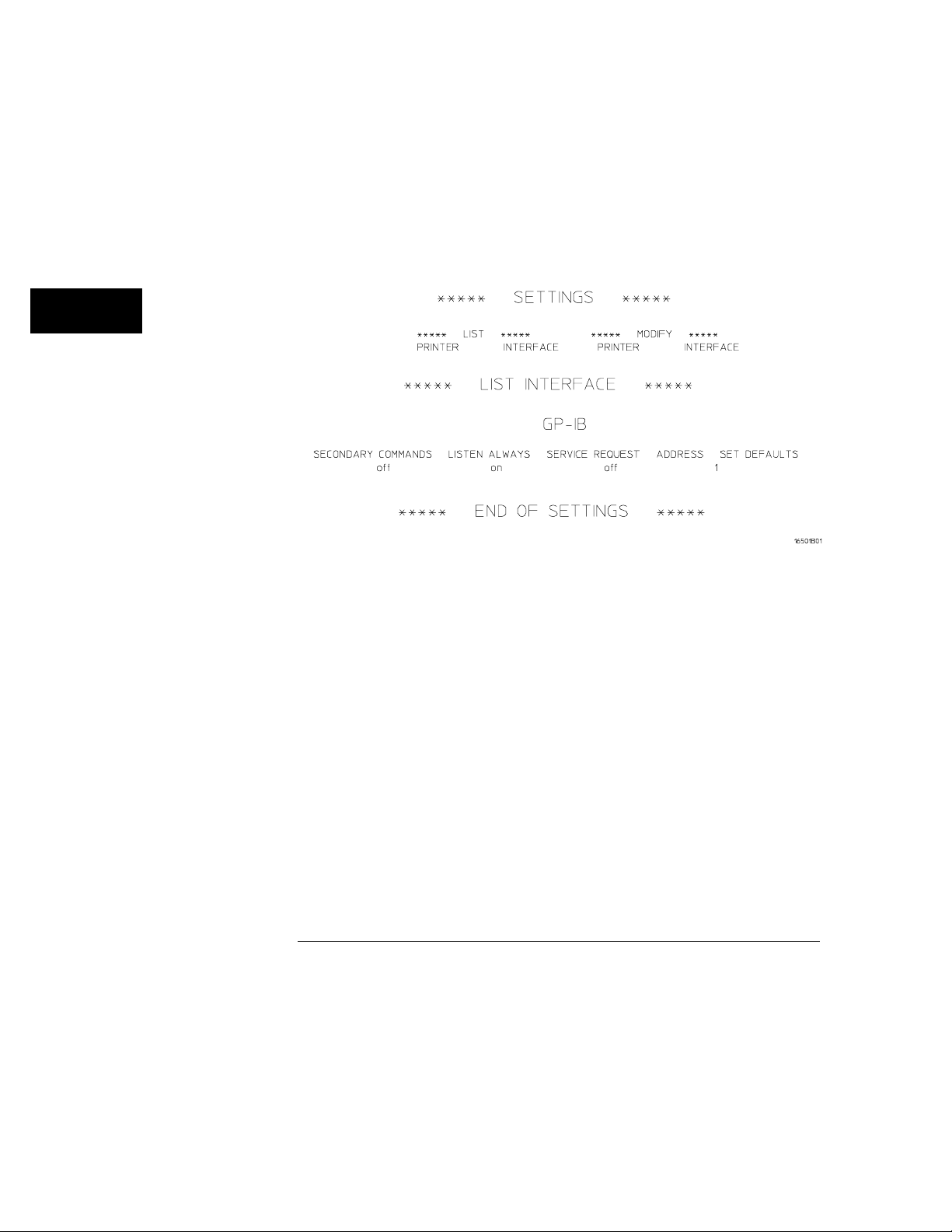
Connecting a Printer
Connecting to Other Hewlett-Packard Printers
GPIB printers must support Listen Always to work with the instrument. The
HP 82906A graphics printer is not supported because it does not support
Listen Always on GPIB.
The HP 2932A or HP 2934A option 046 printer is configured from the front
panel of the printer, instead of with switches on the rear panel. The correct
configuration for the analyzer is shown.
Front Panel Configuration for the HP 2932A or 2934A Option 046
See Also The Programming Reference Manual for information on setting up an
external controller to activate the printer.
5–16
Page 90
Connecting a Printer
Printing the Display
Printing the Display
After connecting the printer to the instrument and setting the printer and
instrument configurations, apply power to the printer.
Each menu has a Print field in the upper-right corner. Select the Print field
and a pop-up appears, displaying your choices.
Cancel is used to stop the instrument from sending data.
•
Print Screen prints everything shown on the screen.
•
Print All (available only in certain menus) prints all of the information
•
listed for that display, including any listings that do not appear on screen.
These listings can be 80 or 132 characters wide, depending on the Print
Width setting.
Print Disk is used to print measurement data to a DOS or LIF disk, which
•
can then be copied into a computer file. The Print Disk function is the
same as the Print All function except the data is printed to a disk.
To initiate a hard copy print, perform the following steps:
Using the arrow keys highlight the Print field, then press the Select key.
1
2 Select the Print Screen or Print All field, then press the Select key.
The instrument does not check the operation of the printer, so no error
messages are displayed.
See Also "Print field" in the Common Menu Fields chapter for more information on
Print Disk.
5–17
Page 91

5–18
Page 92

6
Disk Drive Operations
Page 93

Disk Drive Operations
The logic analyzer has a built in 3.5 inch, double-sided, high-density or
double-density, flexible disk drive. The disk drive is compatible with
both LIF (Logical Interchange Format) and DOS (Disk Operating
System) formats.
This chapter describes the disk operations available in the logic
analyzer and how to use them. It is organized into separate "How to"
examples demonstrating the use of the Disk menu and all the disk
operations.
The Disk Operations
Nine disk operations are available:
• Autoload
Designates a set of configuration files to be loaded automatically the
next time the analyzer is turned on.
• Copy
Any file can be copied from one disk to another, from one directory to
another, or to the same disk.
• Duplicate Disk
All volume labels, directories, and file positions from one disk are
copied exactly to another disk. The new disk is formatted to match
the source disk if it is required. All files on the destination disk will be
destroyed with this operation.
• Format Disk
Any double-sided, double-density, 3.5-inch flexible disk can be
formatted in either LIF or DOS format. The directory and all files on
the disk will be destroyed with this operation.
6–2
Page 94

Disk Drive Operations
• Load
Instrument system configurations, analyzer measurement setups,
including measurement data, and inverse assembler files for the
analyzer can be loaded from the disk drive.
• Make Directory
This function creates a new directory on a DOS disk. Files can me
saved or copied to the new directory isong the store and copy
commands.
• Pack Disk
This function packs files on a LIF disk. Packing removes all empty or
unused sectors between files on a disk so that more space is available
for files at the end of the disk.
• Purge
Any file on a disk can be purged (deleted) from the disk.
• Rename
Any filename on a disk can be changed to another name.
• Store
Instrument system configurations and analyzer measurement setups
including measurement data can be stored to the disk drive.
Disk Operation Safeguards
If there is a problem or additional information is needed to execute an
operation, a pop-up appears near the center of the screen displaying
the status of the operation (for example, it displays an error message
or prompts you to swap disk).
If executing a disk operation could destroy or damage a file, a pop-up
appears when you select Execute. If you don’t want to complete the
operation, select Cancel to cancel the operation. Otherwise, select
Continue and the operation will be continued.
6–3
Page 95
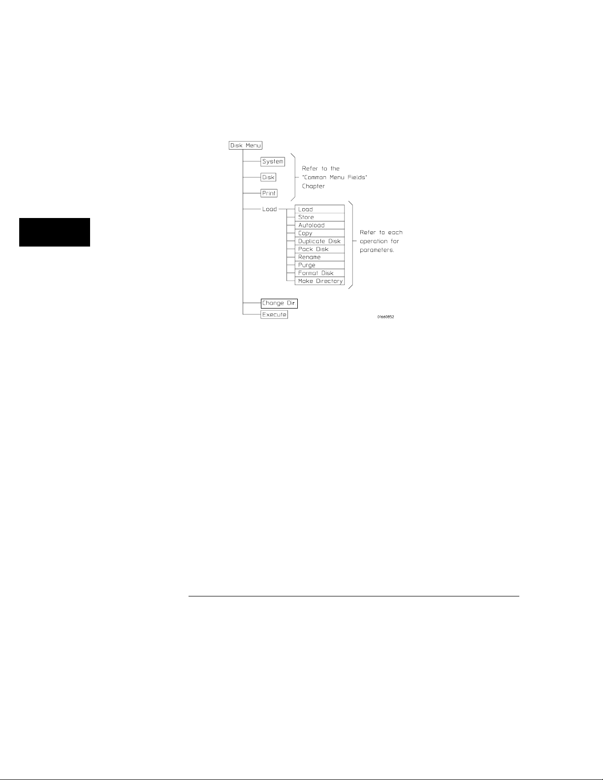
Disk Drive Operations
Menu Map
The figure below displays a menu map for the System Disk menu.
Disk Drive Menu Map
6–4
Page 96
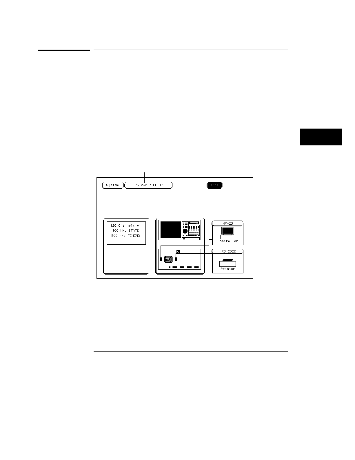
Disk Drive Operations
How to Access the Disk Menu
How to Access the Disk Menu
To access the System Disk menu, perform the following steps:
1 Press the System MENU key.
If you have just turned on the instrument, or if you have not accessed any
System menus since powerup, the first menu displayed is the Disk menu.
If you are not in the Disk menu, continue with steps 2 and 3.
Press the arrow keys to move the cursor to the menu name field as
2
shown below, then press the
3 Press the arrow keys or turn the knob to highlight the Disk field, then
press the
If you have a disk installed when the Disk menu is accessed, the analyzer
automatically reads and displays all files on the disk.
Select key.
Menu name field (displays
Printer/Controller on 1664A)
Select key.
Menu Name Field
6–5
Page 97
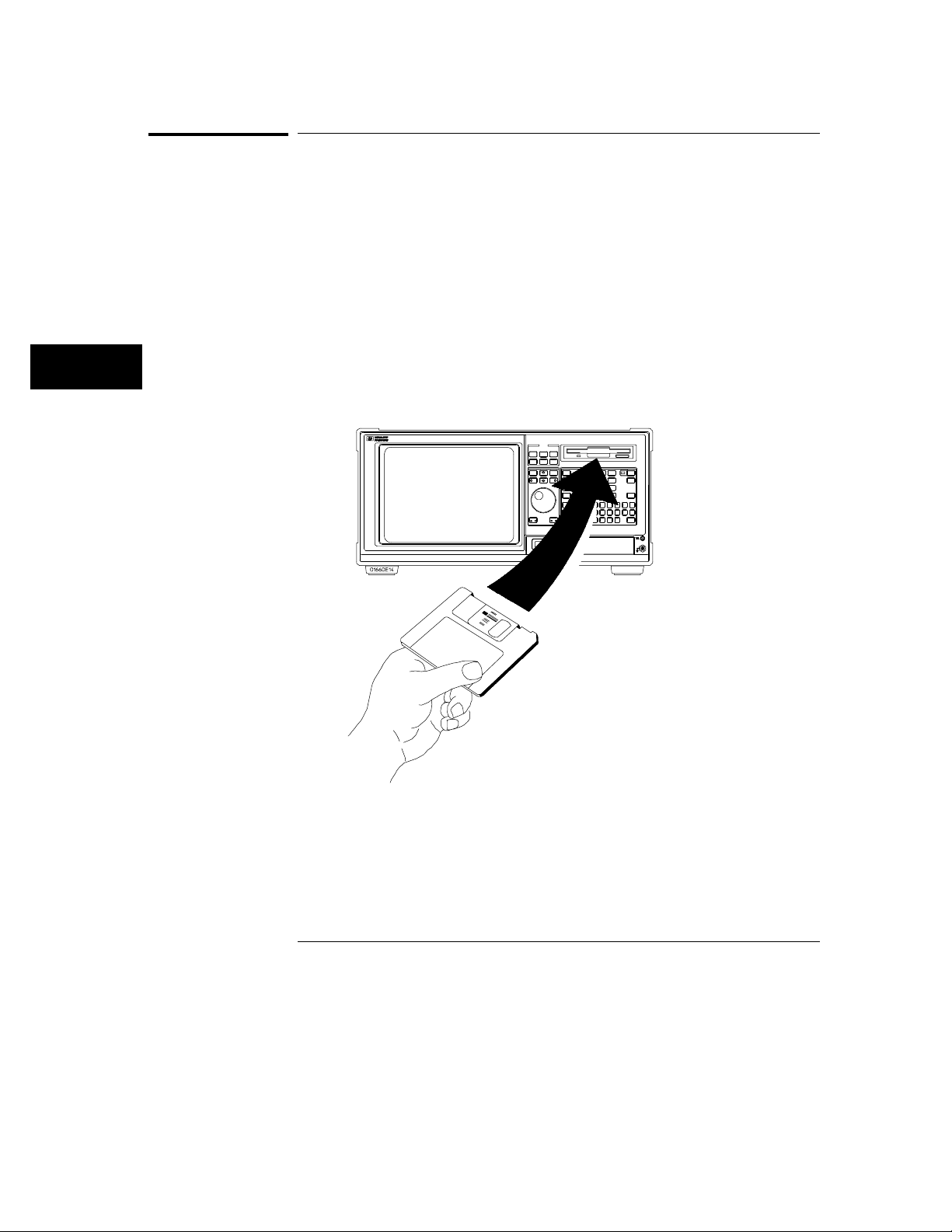
Disk Drive Operations
How to Install a Disk
How to Install a Disk
To install a flexible disk into the disk drive, perform the following steps:
1 Hold the disk so the disk label is on top and the metal auto-shutter is
away from you. See the figure below.
2 Push the disk gently, but firmly, into the disk drive until it clicks into
place.
You can use double-sided, double-density and double-sided, high-density
disks.
To display all files on any disk, insert the disk into the drive, then turn the
knob.
Installing a Disk
6–6
Page 98
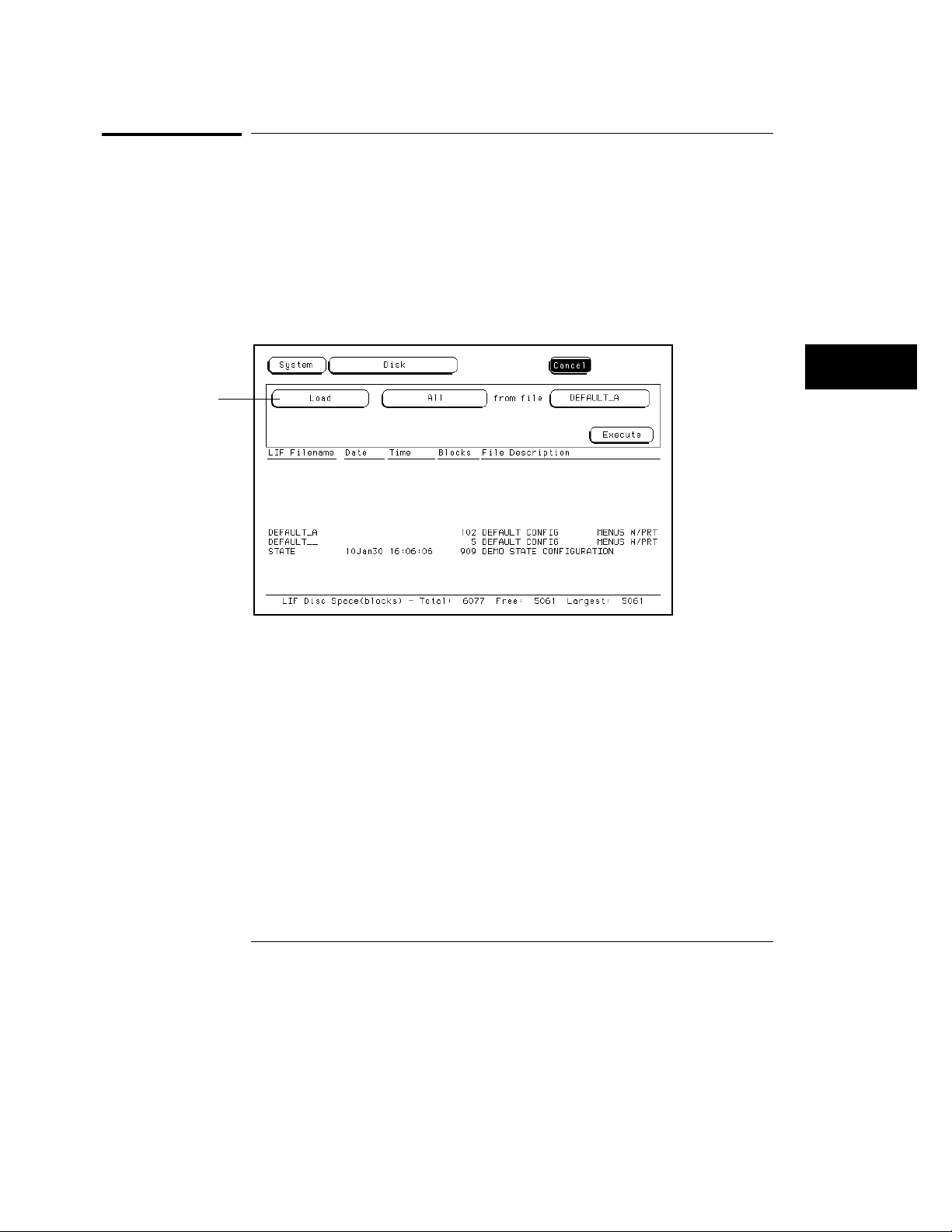
Disk operation field
Disk Drive Operations
How to Select a Disk Operation
How to Select a Disk Operation
Although some default values are provided for disk operations, a disk
operation may require additional information from the user. This information
is entered in the appropriate fields within each disk operation.
To select a disk operation, perform the following steps:
Press the arrow keys to highlight the disk operation field shown in the
1
figure below. Then press the
Select key.
Disk Operation Field
2 Turn the knob to highlight the desired disk operation field, then press
Done or Select key.
the
6–7
Page 99
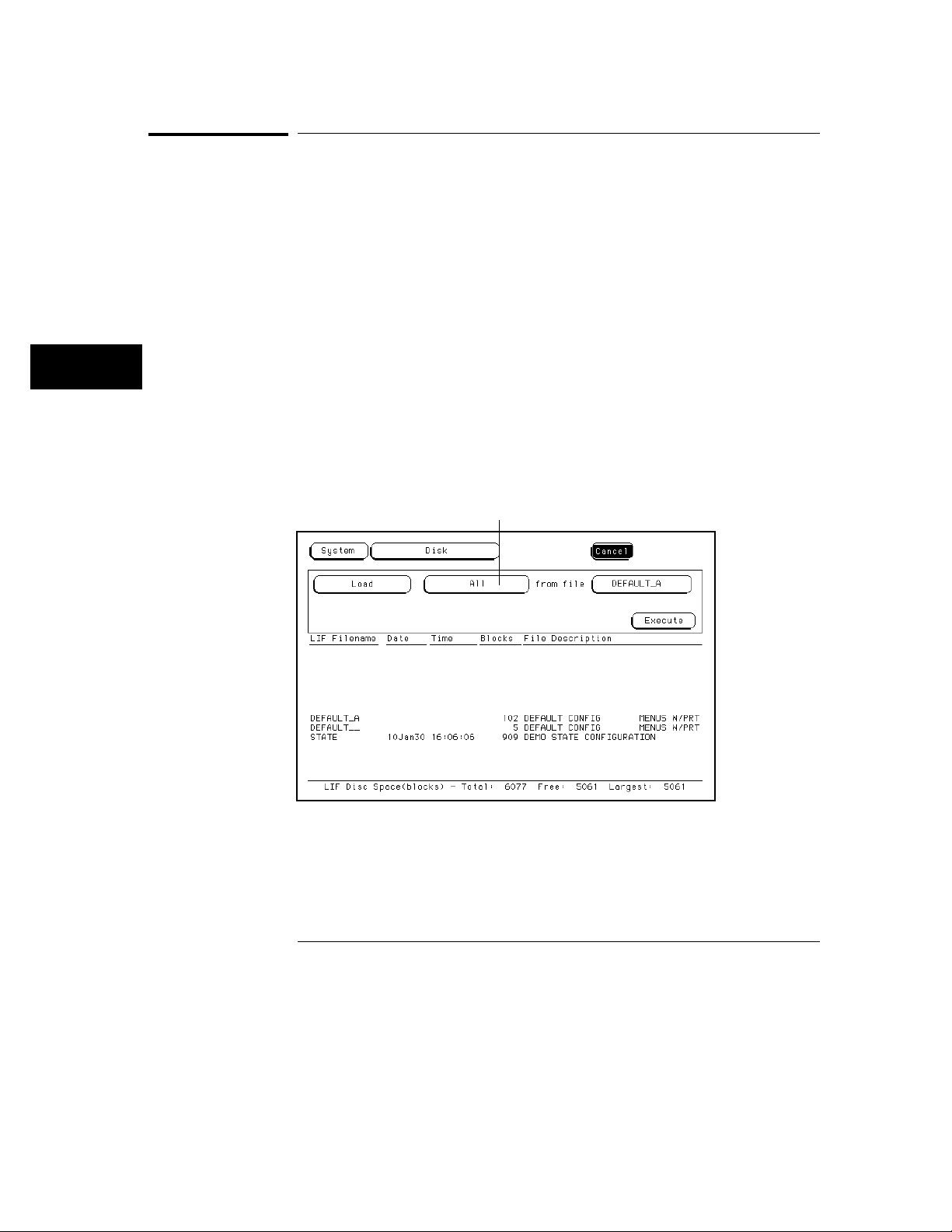
Disk Drive Operations
How to Load a File
How to Load a File
The Load operation allows you to load prestored configuration files. Use this
operation when you want to quickly restore the analyzer to a configuration
used in a previous measurement or condition.
When configurations are stored to the disk, you are given the option to store
System only, Analyzer only, or All (System and Analyzer). So, when you load
a file into the analyzer, you are given the same options.
To load a file from the disk, perform the following steps:
Insert the source disk into the disk drive.
1
2 Select the Load disk operation.
When the Load selection is made, the analyzer reads the disk directory and
displays a list of all files on the disk.
Press the arrow keys to move the cursor to the file type field shown
3
below, then press the
Select key.
File type field
File Type Parameter Field
6–8
Page 100
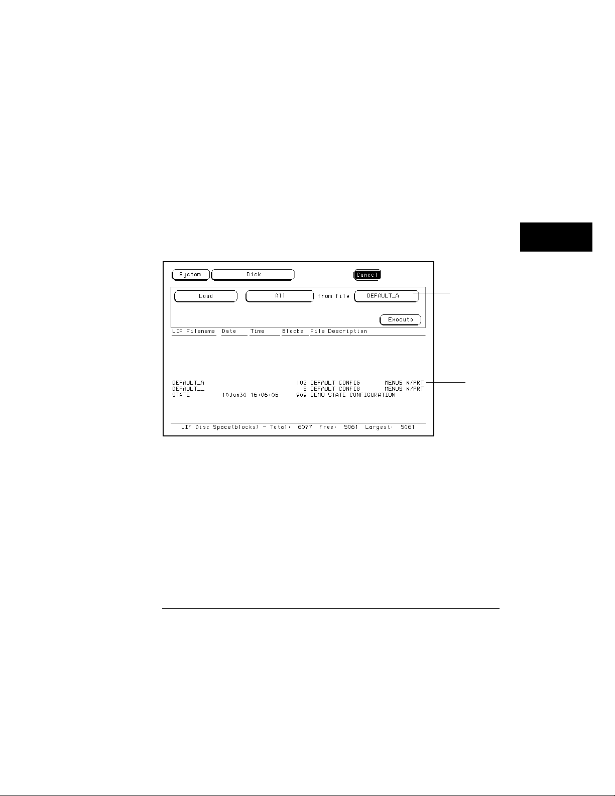
Disk Drive Operations
How to Load a File
4 Turn the knob to highlight the file type you want to load, then press
Select key.
the
The System choice loads things like Bus and display configurations.
The Analyzer choice loads analyzer menus and measurement data.
Turn the knob and notice the changing filenames in the filename field
5
shown below, and how the cursor bar scrolls the list of available files.
Using the knob, scroll to the filename you want to load.
The two spaces(_ _) after the filename designates that this file is for the
system. One space and a letter (for example, "_A") after the filename
designates that the file is for the analyzer.
Filename Selection
Filename field
6 Press the arrow keys to highlight the Execute field, then press the
Select key.
The disk drive indicator light illuminates as the file is being loaded.
Scroll bar
6–9
 Loading...