

Page 1

HP 8935 CDMA Cellular/PCS Bas e St ati o n
Main Menu
Test Set
CDMA Base Station Tests
Application Guide
Firmware Version: A.01.00 and above
HP Part N u mber E6380-90 016
Revision A
Printed in U.S.A.
November 1997
© Copyright 1997 Hewlett-Packard Company
Page 2

Notice
Main Menu
Information contained in this document is subject to change without
notice.
All Rights Reserved. Reproduction, adaptation, or translation without
prior written permission is prohibited, except as allowed under the
copyright laws.
This material may be reproduced by or for the U.S. Government
pursuant to the Copyright License under the clause at DFARS
52.227-7013 (APR 1988).
2
Page 3

Manufacturer’s Declaration
Main Menu
This statement is provided to comply with the requirements of the
German Sound Emission Directive, from 18 January 1991.
This product has a sound pressure emiss ion (a t the op er ato r posit ion) <
70 dB(A).
• Sound Pressure Lp < 70 dB(A).
• At Operator Position.
• Normal Operation.
• Accordin g to ISO 7779:1 988/EN 27779: 1991 (Type Test).
Herstellerbesch einigu ng
Diese Information steht i m Zusammenhang mit den Anf orderungen der
Maschinenlärminformationsverordnung vom 18 Januar 1991.
• Schalldruckpegel Lp < 70 dB (A ).
• Am Arbe it splatz.
• Normaler Betrieb.
• Nach ISO 7779:1988/EN 27779:1991 (Typprüfung).
3
Page 4
Safety
!
Main Menu
GENERAL
This product and related documentation must be reviewed for
familiarization with safety markings and instructions before operation.
This product has been designed and tested in accordance with IEC
Publication 1010, "Safety Requirements for Electronic Measuring
Apparatus," and has been supplied in a safe condition. This instruction
documentation contains information and warnings which must be
followed by the user to ensure safe operation and to maintain the
product in a safe condition.
SAFETY SYMBOLS
Indicates instrument damage can occur i f indic ated operat ing limits a re
exceeded. Refer to the instructions in this guide.
Indicates hazardous voltages.
Indicates earth (ground) terminal
WARNING A WARNING note denotes a hazard. It calls attention to a
procedure, practice, or the like, which, if not correctly
performed or adhered to, coul d result in personal inj ury. Do not
proceed beyond a WARNING sign until the indicated conditions
are fully understood and met.
CAUTION A CAUTION note denotes a hazard. It calls attention to an operation
procedure, practice, or the like, which, if not correctly performed or
adhered to, could result in damage to or destruction of part or all of the
product. Do not proceed beyond an CAUTION note until the indicated
conditions are fully understood and met.
Safety Considerations for this Instrument
4
Page 5
WARNING This product is a Safety Class I instrument (provided with a
Main Menu
protective earthing ground incorporated in the power cord).
!
The mains plug shall only be inserted in a socket outlet
provided with a protective earth contact. Any interruption of
the protective conductor inside or outside of the product is
likely to make the product dangerous. Intentional interruption
is prohibited.
Do not expose to or operate this instrument in outdoor
!
atmospheric conditions such as direct rain, hail, sleet, snow,
icing, sunshine or wind. Operate this instrument only within its
specified temp erature humidity conditions.
This instrument is equipped with internal ground fault circuit
!
interrupter class A.
• This device does not protect against electrical shock due to
contact with both circuit conductors or a fault in supply
wiring to product.
• Do not use extension cord to connect this product to power
receptacle. Attention-ne pas utiliser d e rallonge pour
raccorder le detecteur-disjoncteur a la prise de courant.
• Replace cordset only with HP 8120 series. Attention Remplacer uniquement par un cor do n amovible numero
8120.
• Do not use in wet location. Ne pas utiliser dans un
emplacement mouille.
WARNING Whenever it is likely that the protection has been impaired, the
instrument must be made inoperative and be secured against
any unintended operation.
If this instrument is to be energized via an autotransformer (for
voltage reduction), make sure the common terminal is
connected to the earth terminal of the power source .
If this product is not used as specified, the protection provided
by the equipment could be impaired. This product must be used
in a normal condition (in which all means for protection are
intact) only.
No operator serviceable parts in this product. Refer servicing to
qualified personnel. To prevent electrical shock, do not remove
covers.
Servicing inst ructions are for use by qualified personnel only.
To avoid electrical shock, do not perform any servicing unless
you are qualified to do so.
5
Page 6

The opening of covers or removal of parts is likely to expose
Main Menu
dangerous voltages. Disconnect the product from all voltage
sources while it is being opened.
Adjustments described in the manual are performed with
power supplied to the instrument while protective covers are
removed. Energy available at many points may, if contacted,
result in personal injury.
The power cord is connected to internal capacitors that my
remain live for 5 seconds after disconnecting the plug from its
power supply.
For Continued protection against fire hazard, replace the line
fuse(s) only with 250 V fuse(s) or the same current rating and
type (for example, normal blow or time delay). Do not use
repaired fuses or short circuited fuseholders. FUSE: T 5.0A
CAUTION Always use the three-prong ac power cord supplied with this product.
Failure to ensure adequate earth grounding by not using this cord may
cause personal injury and/or product damage.
This product is designed for use in Installation Category II and
Pollution Degree 2 per IEC 1010 and IEC 664 respectively. For indoor
use only.
This product has autoranging line voltage input, be sure the supply
voltage is within the specified range.
Ventilation Requirements: When installing the product in a cabinet,
the convection into and out of the product must not be restricted. The
ambient temperature (outside the cabinet) must be less than the
maximum operating temperature of the product by 4° C for every 100
watts dissipated in the cabinet. If the total power dissipated in the
cabinet is greater than 800 watts, then forced convection must be used.
To prevent electrical shock, disconnect instrument from mains (line)
before cleaning. Use a dry cl oth or one s lightl y da mpened wi th water to
clean the external case parts. Do not attempt to clean internally.
6
Page 7

Product Markings
Main Menu
CE - the CE mark is a registered trademark of the European
Community. A CE mark accompanied by a year indicated the year the
desi gn was proven.
CSA - the CSA mark is a registered trademark of the Canadian
Standards Association.
CERTIF ICATION
Hewlett-Packard Company certif ies tha t thi s produc t met its publ i shed
specifications at the time of shipment from the factory.
Hewlett-Packard further certifies that its calibration measurements
are traceable to the United States National Institute of Standards and
Technology, to the extent allowed by the Institute’s calibration facility,
and to the calibration facilities of other International Standards
Organization members.
7
Page 8

Warranty
Main Menu
This Hewlett-Packard instrume nt produc t i s warr anted a gainst d ef ec ts
in material and workmanship for a period of one year from date of
shipment. During the warranty period, Hewlett- Packard Company will
at its option, either repair or replace products which prove to be
defective.
For warranty service or repair, this product must be returned to a
service facility designated by HP. Buyer shall prepay shipping charges
to HP and HP shall pay s hipping cha rges, duti es, and taxes for product s
returned to HP from another country.
HP warrants that its software and firmware designated by HP for use
with an instrument will execute its programming instructions when
properly installed on that instrument. HP does not warrant that the
operation of the instrument, or software, or firmware will be
uninterrupted or error free.
LIMITATION OF WARRANTY
The foreg o in g warranty shall n o t a pply to defects resulting from
improper or inadequate maintenance by Buyer, Buyer-supplied
software or inte rfa cing, una uthor ized modification or mi suse, oper ati on
outside of the enviro nmental sp ec ifications for the product, or im proper
site preparation or maintenance.
NO OTHER WARRANTY IS EXPRESSED OR IMPLIED. HP
SPECIFICALLY DISCLAIMS THE IMPLIED WARRANTIES OF
MERCHANTABILITY AND FITNESS FOR A PARTICULAR
PURPOSE.
EXCLUSI VE REMED IE S
THE REMEDIES PROVIDED HEREIN ARE BUYER’S SOLE AND
EXCLUSIVE REMEDIES. HP SHALL NOT BE LIABLE FOR ANY
DIRECT, INDIRECT, SPECIAL, INCIDENTAL, OR
CONSEQUENTIAL DAMAGES, WHETHER BASE ON CONTRACT,
TORT, OR ANY OTHER LEGAL THEORY.
8
Page 9

ASSISTANCE
Main Menu
Main te na n c e A gr e e m en ts
Product maintenance agreements and other customer assistance
agreements are available for Hewlett-Packard products. For any
assistance, contact your nearest Hewlett-Packard Sales and Service
Office.
9
Page 10

Regional Sales Offices
Main Menu
IMPORTANT Regional Sales an d S erv ic e Of f ic es
Eastern USA
Sales Office
Hewlett-Packard Company
2101 Gather Rd.
Rockville, MD 20850
Tel: (301) 258-2000
Southern USA
Sales and Service
Hewlett-Packard Company
1995 North Park Place
Atlanta, GA 30339
Sales
Tel: (404) 955-1500
Fax: (404) 980-7292
Service
Tel: (404) 850-2544
Fax: (404) 980-7292
Western USA
Sales and Service
Hewlett-Packard Company
24 Inverness Place East
Englewood, CO 80112
Sales
Tel: (303) 649-5000
Fax: (303) 649-5787
Service
Tel: (303) 649-5512
Fax: (303) 649-5787
Eastern USA
Sales Office
Hewlett-Packard Company
2101 Gather Rd.
Rockville, MD 20850
Tel: (301) 258-2000
Southern USA
Service Center
Hewlett-Packard Company
930 E. Campbell Road
Richardson, TX 75081
Tel: (214) 699-4331
Western USA
Sales and Service
Hewlett-Packard Company
1421 South Manhattan Avenue
Fullerton, CA 92631
Sales
Tel: (714) 999-6700
Fax: (714) 778-3033
Service
Tel: (714) 758-5490
Fax: (714) 778-3033
Midwestern USA
Sales and Service
Hewlett-Packard Company
5201 Tollview Drive
Rolling Meadows, IL 60008
Tel: (708) 342-2000
Western US A
Service Center
Hewlett-Packard Company
301 E. Evelyn Avenue
Mountain View, CA 94041
Tel: (415) 694-2000
Fax: (415) 694-0601
United States of America
Customer I nformation Center
Hewlett-Packard Company
Tel: (800) 752-0900
6:00 am to 5:00 pm Pacific Tim e
Parts Direct: 1-800-227-8164
South Eastern Europe
Sales and Service
Hewlett-Packard Ges. m.b.h.
Liebigasse 1
P.O. Box 72
A-1222 Vienna, Austria
Telephone: 43 222 2500 0
Telex: 13 4425
10
European Multicountry Region
Sales and Service
Hewlett-Packard S.A.
P.O. Box 95
150, Route dv Nant_dl_AVRIL
CH-1217 Meyrin 2
Geneva, Switzerland
Telephone: (41/2 2) 780-8111
Fax: (41/22) 780-8542
North e rn Europe
Sales and Service
Hewlet t- P a cka r d Ne de rland B.V.
Startbaan 16
1187 XR
Amstelveen, The Netherlands
P.O. Box 667
Telephone: 31/ 20 5476911 X 6631
Fax: 31-20-6471825NL
Page 11

Asia
Main Menu
Sales and Service
Hewlett-Packard Asia Ltd.
22-30/F Peregrine Tower
Lippo Center
89 Queensway, Central
Hong Kong
G.P.O. Box 863 Hong Kong
Telephone: 852-848-7777
Fax: 852-868-4997
Japan
Sales and Service
Yokogawa-Hewlett-Packard Ltd.
3-29-21, Takaido-Higashi
Suginami-Ku, Tokyo 168
Telephone: 81 3 3331-6111
Fax: 81 3 3331-6631
International Sales Branch
Headquarter s
Sales and Service
Hewlett-Packard S.A.
39 Rue Veyrot
P.O. Box 365
1217 Meyrin 1
Geneva, Switzerland
Telephone: 41-22-780-4111
Fax: 41-22-780-4770
Australi a , Ne w Zea l a nd
Sales and Service
Hewlett-Packard Ltd.
P.O. Box 221
31-41 Joseph Stre et
Blackburn, Victoria 3130
Telephone: (61/ 3) 895-2895
Fax: (61/3) 898-9257
Canada
Service Center
Hewlett-Packard Ltd.
11120 178 Street
Edmonton, Alberta T5S 1P2
Canada
Telephone: (403) 486-6666
Fax: (403) 489-8764
Canada
Sales and Service
Hewlett-Pac ka rd (Canada) Ltd.
5150 Spectrum Way
Mississauga, Ontario L4W 5G1
Canada
Telephone: (416) 206-4725
Fax: (416) 206-4739
Latin America
Hewlett-Packard Company
LAHQ Mexico City
Col. Lomas de Virreyes
11000 Mexico D.F.
Mexico
Telephone: (52/ 5) 326-4000
Fax: (52/5) 202 7718
Canada
Service Center
Hewlett-Packard Company
17500 Transcanada Highway
S. Serv Road
Kirkland, Quebec H9J 2X 8
Canada
Telephone: (416) 206-3295
United Kingdom
Sales and Service
Hewlett-Packard Ltd.
Cain Road
Amen Corner
Bracknell, Berkshire
RG12 1HN
United Kingdom
Telephone: 44 344 360000
11
Page 12

12
Main Menu
Page 13

Contents
Main Menu
In This Manual. . . . . . . . . . . . . . . . . . . . . . . . . . . . . . . . . . . . . . . . . . . . 17
1. Getting Started with CDMA Test
About the Test Set. . . . . . . . . . . . . . . . . . . . . . . . . . . . . . . . . . . . . . . . . 20
Product Description . . . . . . . . . . . . . . . . . . . . . . . . . . . . . . . . . . . . . . 20
Who Should Use this Test Set . . . . . . . . . . . . . . . . . . . . . . . . . . . . . . 21
Batteries . . . . . . . . . . . . . . . . . . . . . . . . . . . . . . . . . . . . . . . . . . . . . . . 21
Getting Help . . . . . . . . . . . . . . . . . . . . . . . . . . . . . . . . . . . . . . . . . . . . 22
What’s Included with this Test Set . . . . . . . . . . . . . . . . . . . . . . . . . . 23
Manual and Automatic Operation Modes . . . . . . . . . . . . . . . . . . . . . . 24
IBASIC programs . . . . . . . . . . . . . . . . . . . . . . . . . . . . . . . . . . . . . . . . 24
Maximizing the Accuracy of Your Measurements. . . . . . . . . . . . . . . . 25
Calibration . . . . . . . . . . . . . . . . . . . . . . . . . . . . . . . . . . . . . . . . . . . . . 25
Temperature Compensation . . . . . . . . . . . . . . . . . . . . . . . . . . . . . . . 25
When to zero the power . . . . . . . . . . . . . . . . . . . . . . . . . . . . . . . . . 25
Display a CDMA Signal (Loopback Test). . . . . . . . . . . . . . . . . . . . . . . 26
Connections for CDMA Loopback Test . . . . . . . . . . . . . . . . . . . . . . . 26
Get Started with the Test Set . . . . . . . . . . . . . . . . . . . . . . . . . . . . . . 26
Generate a CDMA Signal. . . . . . . . . . . . . . . . . . . . . . . . . . . . . . . . . . 28
Display a CDMA Signal. . . . . . . . . . . . . . . . . . . . . . . . . . . . . . . . . . . 28
What to Do Next. . . . . . . . . . . . . . . . . . . . . . . . . . . . . . . . . . . . . . . . . 28
Table of Contents
Table of Contents
2. Testing CDMA Base Stations
Tests That You Can Perform with the Test Set. . . . . . . . . . . . . . . . . . 30
Setup and Configuration. . . . . . . . . . . . . . . . . . . . . . . . . . . . . . . . . . . . 31
Connections Betw een the Test Se t and th e Dev ice Un d er Tes t (D UT)
32
Synchronizing Your Base Station to the Test Set . . . . . . . . . . . . . 32
Configuring the Test Set with Your Base Station’s Information. . . 33
Choosing Between RF In/Out, Antenna and Duplex Ports . . . . . 34
Saving and Recalling Instrument Setups. . . . . . . . . . . . . . . . . . . . . 36
To Save an Instrument Setup . . . . . . . . . . . . . . . . . . . . . . . . . . . . 36
To Recall an Instrument Setup . . . . . . . . . . . . . . . . . . . . . . . . . . . 36
To Choose the Save/Recall Location . . . . . . . . . . . . . . . . . . . . . . . 36
Average Power. . . . . . . . . . . . . . . . . . . . . . . . . . . . . . . . . . . . . . . . . . . . 37
Prerequisites. . . . . . . . . . . . . . . . . . . . . . . . . . . . . . . . . . . . . . . . . . . . 37
Procedure . . . . . . . . . . . . . . . . . . . . . . . . . . . . . . . . . . . . . . . . . . . . . . 37
Results. . . . . . . . . . . . . . . . . . . . . . . . . . . . . . . . . . . . . . . . . . . . . . . . . 38
Notes . . . . . . . . . . . . . . . . . . . . . . . . . . . . . . . . . . . . . . . . . . . . . . . . . . 39
Channel Power. . . . . . . . . . . . . . . . . . . . . . . . . . . . . . . . . . . . . . . . . . . . 40
Prerequisites. . . . . . . . . . . . . . . . . . . . . . . . . . . . . . . . . . . . . . . . . . . . 40
Channel Power Calibration Procedure . . . . . . . . . . . . . . . . . . . . . . . 40
Channel Power Measurement Procedure . . . . . . . . . . . . . . . . . . . . . 41
Results. . . . . . . . . . . . . . . . . . . . . . . . . . . . . . . . . . . . . . . . . . . . . . . . . 42
Notes . . . . . . . . . . . . . . . . . . . . . . . . . . . . . . . . . . . . . . . . . . . . . . . . . . 42
Code Domain Testing . . . . . . . . . . . . . . . . . . . . . . . . . . . . . . . . . . . . . . 43
Prerequisites. . . . . . . . . . . . . . . . . . . . . . . . . . . . . . . . . . . . . . . . . . . . 43
Procedure . . . . . . . . . . . . . . . . . . . . . . . . . . . . . . . . . . . . . . . . . . . . . . 44
13
Page 14

Contents
Main Menu
Results. . . . . . . . . . . . . . . . . . . . . . . . . . . . . . . . . . . . . . . . . . . . . . . . . 45
Code Domain Measurements. . . . . . . . . . . . . . . . . . . . . . . . . . . . . . . 45
Code Domain Power . . . . . . . . . . . . . . . . . . . . . . . . . . . . . . . . . . . . 45
Fast Power. . . . . . . . . . . . . . . . . . . . . . . . . . . . . . . . . . . . . . . . . . . . 46
Code Domain Phase . . . . . . . . . . . . . . . . . . . . . . . . . . . . . . . . . . . . 46
Code Domain Timing . . . . . . . . . . . . . . . . . . . . . . . . . . . . . . . . . . . 46
Time Offset . . . . . . . . . . . . . . . . . . . . . . . . . . . . . . . . . . . . . . . . . . . 47
Frequency Error . . . . . . . . . . . . . . . . . . . . . . . . . . . . . . . . . . . . . . . 47
Carrier Feedthrough. . . . . . . . . . . . . . . . . . . . . . . . . . . . . . . . . . . . 47
Code Domain Notes . . . . . . . . . . . . . . . . . . . . . . . . . . . . . . . . . . . . . . 48
Rho (Modulation Quality) . . . . . . . . . . . . . . . . . . . . . . . . . . . . . . . . . . . 49
Prerequisites. . . . . . . . . . . . . . . . . . . . . . . . . . . . . . . . . . . . . . . . . . . . 49
Procedure . . . . . . . . . . . . . . . . . . . . . . . . . . . . . . . . . . . . . . . . . . . . . . 50
Results. . . . . . . . . . . . . . . . . . . . . . . . . . . . . . . . . . . . . . . . . . . . . . . . . 50
Transmit Spectrum . . . . . . . . . . . . . . . . . . . . . . . . . . . . . . . . . . . . . . . . 51
Prerequisites. . . . . . . . . . . . . . . . . . . . . . . . . . . . . . . . . . . . . . . . . . . . 52
Procedure . . . . . . . . . . . . . . . . . . . . . . . . . . . . . . . . . . . . . . . . . . . . . . 52
3. Utility Procedures
Beeper. . . . . . . . . . . . . . . . . . . . . . . . . . . . . . . . . . . . . . . . . . . . . . . . . . . 54
Beeper Control . . . . . . . . . . . . . . . . . . . . . . . . . . . . . . . . . . . . . . . . . . 54
Changing Between Channel Mode and Frequency Mode . . . . . . . . . . 55
Procedure to Change Between Channel and Frequency Modes . . . 55
Measuring Insertion Losses . . . . . . . . . . . . . . . . . . . . . . . . . . . . . . . . . 56
Memory Cards . . . . . . . . . . . . . . . . . . . . . . . . . . . . . . . . . . . . . . . . . . . . 57
Memory Cards and Intialization . . . . . . . . . . . . . . . . . . . . . . . . . . . . 57
Initializing SRAM Cards for Save/Recall and Data C olle ction . . 57
Oscilloscope . . . . . . . . . . . . . . . . . . . . . . . . . . . . . . . . . . . . . . . . . . . . . . 58
Selecting the Oscillo sc op e’s Inp u t . . . . . . . . . . . . . . . . . . . . . . . . . . . 58
Selecting the Oscillo sc op e’s F ilte rs . . . . . . . . . . . . . . . . . . . . . . . . . . 59
Triggering the Osc illo sc ope . . . . . . . . . . . . . . . . . . . . . . . . . . . . . . . . 59
Using the Marker. . . . . . . . . . . . . . . . . . . . . . . . . . . . . . . . . . . . . . . . 60
Online Help . . . . . . . . . . . . . . . . . . . . . . . . . . . . . . . . . . . . . . . . . . . . . . 61
Help Screen Display. . . . . . . . . . . . . . . . . . . . . . . . . . . . . . . . . . . . . . 61
Ports: HP-IB, Serial and Parallel. . . . . . . . . . . . . . . . . . . . . . . . . . . . . 62
HP-IB Port . . . . . . . . . . . . . . . . . . . . . . . . . . . . . . . . . . . . . . . . . . . . . 62
Controlling the H P-IB P ort . . . . . . . . . . . . . . . . . . . . . . . . . . . . . . 62
Serial Ports . . . . . . . . . . . . . . . . . . . . . . . . . . . . . . . . . . . . . . . . . . . . . 62
Configuring Serial Ports. . . . . . . . . . . . . . . . . . . . . . . . . . . . . . . . . 62
Using Serial Ports for Printing . . . . . . . . . . . . . . . . . . . . . . . . . . . 63
Configuring Serial Port 9 for IBASIC Communications. . . . . . . . 63
Configuring Serial Ports 10 and 11 . . . . . . . . . . . . . . . . . . . . . . . . 63
Parallel Ports . . . . . . . . . . . . . . . . . . . . . . . . . . . . . . . . . . . . . . . . . . . 64
Power Measurements . . . . . . . . . . . . . . . . . . . . . . . . . . . . . . . . . . . . . . 65
Average Power . . . . . . . . . . . . . . . . . . . . . . . . . . . . . . . . . . . . . . . . . . 65
Channel Power . . . . . . . . . . . . . . . . . . . . . . . . . . . . . . . . . . . . . . . . . . 65
Code Domain Power . . . . . . . . . . . . . . . . . . . . . . . . . . . . . . . . . . . . . . 65
Fast Power . . . . . . . . . . . . . . . . . . . . . . . . . . . . . . . . . . . . . . . . . . . . . 65
TX Power. . . . . . . . . . . . . . . . . . . . . . . . . . . . . . . . . . . . . . . . . . . . . . . 65
14
Page 15

Contents
Main Menu
Printing . . . . . . . . . . . . . . . . . . . . . . . . . . . . . . . . . . . . . . . . . . . . . . . . . 66
Configuring the Test Set for Printing . . . . . . . . . . . . . . . . . . . . . . . . 66
Printing a Screen . . . . . . . . . . . . . . . . . . . . . . . . . . . . . . . . . . . . . . . . 67
Measuring Swept Return Loss . . . . . . . . . . . . . . . . . . . . . . . . . . . . . . . 68
Software: Loading . . . . . . . . . . . . . . . . . . . . . . . . . . . . . . . . . . . . . . . . . 71
Tracking Generator. . . . . . . . . . . . . . . . . . . . . . . . . . . . . . . . . . . . . . . . 72
Using the Tracking Generator . . . . . . . . . . . . . . . . . . . . . . . . . . . . . . 72
User Keys. . . . . . . . . . . . . . . . . . . . . . . . . . . . . . . . . . . . . . . . . . . . . . . . 74
Displaying the Pre-assigned Local User Keys . . . . . . . . . . . . . . . . . 74
Assigning a Local User Key. . . . . . . . . . . . . . . . . . . . . . . . . . . . . . . . 74
Assigning a Global User Key. . . . . . . . . . . . . . . . . . . . . . . . . . . . . . . 74
To Release a User Key Assignment. . . . . . . . . . . . . . . . . . . . . . . . . . 75
Voltmeter . . . . . . . . . . . . . . . . . . . . . . . . . . . . . . . . . . . . . . . . . . . . . . . . 76
Measuring AC Level and DC Level. . . . . . . . . . . . . . . . . . . . . . . . . . 76
Table of Contents
15
Page 16

Contents
Main Menu
16
Page 17

In This Manual
Main Menu
This manual explains how to use t he HP 8935 to manually te st a CDMA
Base Station.
What is Discussed This Manual
This document presents a step-by-step approach to CDMA base station
testing using the Test Set, including what you need to know before you
can start testing.
What is Not Discussed in this Manual
General operation of the Test Set , such as changing display screens
and their associated controls, is discussed in the Reference Guide
(HP part number E6380- 90019).
Detailed operation of the Test Set’s spectr um analy zer and oscilloscope.
Although there are basic explanations in this manual, more detail is
provided in the Reference Guide.
How to control your base station, switch system, or any other software
or hardware associated with your cell site equipment. Each
manufacturer and cellular service provider has their own cell site
control and base station configuration procedures that go beyond the
scope of this documentation.
In This Manual
In This Manual
How to perform IBASIC programming operations, such as writing,
editing, copying, or cataloguing programs. Programming the
Test Set is explained in the Programming Manual (HP part number
E6380-90018), and the IBASIC language is explained in the
HP Instrument BASIC User’s Handbook (HP part numbe r
E2083-90005).
Conventions Used in This Manual
The following conventions are used throughout this manual to help
clarify instructions and reduce unnecessary text:
Test Set refers to the HP 8935.
Test Set keys are indicated like this:
Test Set screen information, such as a measurement result or an error
message, is shown like this: TX Channel Power -1.3 dBm
Preset
17
Page 18
Which Document is
Main Menu
Required?
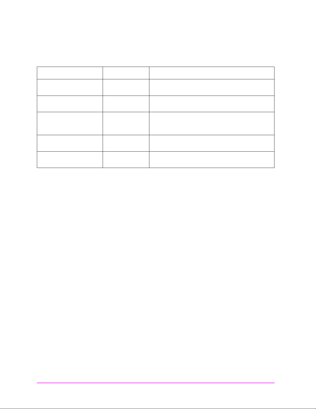
Table 1 Document Navigation
Document Pa rt Num be r Usage
The following documents ar e part of the HP 8935 document set. Use the
table to help you decide which document you need.
CDMA Application
Guide
AMPS Application Guide E6380-90017 Use this manual for makin g AMPS base stat ion
Reference Guide E6380-90019 Use this manual for screen and field descriptio ns
Programmer’s Guide E6380-90018 Use this manual to learn HP-IB syn tax and for
Assembly Level Repair
Guide
E6380-90016 Use this manual for basic CDMA m easure ments
and for getting started with the Test Set.
measurements.
and general operation information about the Test
Set.
learning ho w to program the Test S et.
E6380-90015 Use this manu al to perfor m calibra tion o n th e
Test Set and for gene r al serv ice info rmat io n.
18
Page 19

1 Getting St arted wi th CD MA Test
Main Menu
This chapter introduces you to the HP 8935 Test Set and its CDMA
functions. For information on other functions in the Test Set, see
“Which Document is Required?” on page 18. To proceed immediately to
the test procedures, see “Tests That You Can Perform with the Test
Set” on page 30.
Getting Started with CDMA
Chapter 1
Test
19
Page 20

Getting Started with CDMA Test
Main Menu
About the Test Set
About the Test Set
Product Description
This Test Set is a tool which will help you in testing CDMA base
stations at both the cellular band and the PCS band. It also allows you
to test AMPS base stations. (This guide discusses CDMA testing. For
more information a bo ut AMPS tes ti ng, refer to the Manual AMPS Ba s e
Station Tes t s Guide.)
The Test Set contains a CDMA signal generator and a frequency
translator which allow generati on of CDMA signals at both cellul ar and
PCS frequencies. Other tools include
• Code Domain Analyzer
• CDMA Analyzer
• CDMA Generator
• Spectrum Analyzer
• Power Meter (both wideband and channel)
• Oscilloscope
Other tools include
• AMPS Analyzer
• AC/DC Voltmeter
• Audio and RF Generators
• Built-in IBASIC controll er
20 Chapter 1
Page 21

Getting Started with CDMA Test
Main Menu
About the Test Set
Who Should Use this Test Set
If you are installing, commissioning or maintaining CDMA sites
operating at either the PCS frequencies or cellular frequencies, this
Test set can assist you in testing these base stations.
Batteries
There are two methods by which the Test Set backs up its RAM. One is
a set of two AA batteries mounted behind the rear panel of the Test Set.
You must periodically change these batteries. The second method of
RAM backup is an internal battery. It is not user serviceable.
CAUTION Failure to take prompt action may result in loss of RAM data including
IBASIC programs and SAVE / RECALL states stored in the RAM.
NOTE Do not use rechargeable batteries.
To change the AA batteries, use the following procedure:
1. Turn off power and unplug the Test Set.
Getting Started with CDMA
2. Remove the six screws in the rear panel using a TX-15 TORX (R)
screwdriver.
3. Remove the rear cover.
4. Replace the AA batteries.
5. Replace and reconnect the rear panel. Dispose of used batteries
properly.
Chapter 1
Test
Chapter 1 21
Page 22

Getting Started with CDMA Test
Main Menu
About the Test Set
Getting Help
If you have pro blems using t his Test Se t, and c annot find t he solu tion in
these documents or the Help screens, please use one of the following
contacts:
• Your local or re gional sales office (see "Regional Sales Offices" on
• U.S. Call Center: 800 542-4844
• Korea HP Direct: (82/2) 76 9-0800
• Canada H P Direct: (800) 387-3154
• European Call center: +31 20 547-9990
• Test and Measurement Organization on the web:
page 10)
http://www.tmo.hp.com/
22 Chapter 1
Page 23

What’s Included with this Test Set
Main Menu
The equipment commonly shipped with the base Test Set is listed
below. Options that you order with your Test Set may change this list.
• Test Set
• Documentation
• CDMA Applications Guide
• CD-ROM with the above listed manual, Manual AM PS Base
Station Tests, Assembly Level Repair Manual, Programmer’s
Guide, and HP 8935 Reference Guide in Adobe™ Acrobat Reader
format (.pdf).
• Power cord
• Cover for the front panel of the Test Set
Getting Started with CDMA Test
About the Test Set
Getting Started with CDMA
Test
Chapter 1
Chapter 1 23
Page 24

Getting Started with CDMA Test
Main Menu
Manual and Automatic Operation Modes
Manual and Automatic Operation Modes
You can operate the Test Set in either of two modes: Manual or
Automatic. Controlling the Test Set with the keypad is Manual
Operation. Controlling the Test Set with a program is Automatic
Operation.
Use Manual Mode when you want to control the Tes t Set w it h the f ron t
panel. Manual operation is described in this document.
Use Automatic Mode when you want to control the Test Set with its
internal IBASIC controller . To use the Test Set in Automatic Mode, you
must load an IBASIC program into the Test Set’s memory.
IBASIC programs
You can obtain an IBASIC program in two ways: either write it
yourself, or purchase a software package from Hewlett-Packard. To
write programs yourself, refer to the Programmer’s Guide, included
with the Test Set’s documentation.
Many of HP’s software packages are manufacturer-specific packages.
Manufacturer-specific software packages provide automated testing of
the manufacturer’s base station to greatly reduce test times and
provide test setup repeata bility. Once configured, the software typic ally
controls both the base station and the Test Set and prompts the user to
make the required connections during testing. Test results can be
printed and/or saved to a file for later use. Contact your local HP Sales
Office to find out which software packages are currently available.
24 Chapter 1
Page 25

Getting Started with CDMA Test
Main Menu
Maximizing the Accuracy of Your Measurements
Maximizing the Accuracy of Your Measurements
This Test Set is designed to make highly accur ate measurements.
However, to ensure that you have the most accurate measurements
available, you can perform the following tasks:
Calibration
You should calibrate the Test Set w henever you change a module or a dd
a hardware option. You may want to calibrate when you upgrade
firmware. See the Assembly Level Repair Manual for calibra t ion
procedures.
There is also a field named Calibrate in the CDMA ANALYZER
screen. This field is used t o cali b rate the Channel Power measurement.
See “Channel Power” on page 40. Note that cables must be removed
from the Test Set’s inputs before using Calibrate.
Temperature Compensation
The Test Set is internally compensated for temperature. However, you
will find that on some screens a zeroing f unction a ppears. F or example,
in the RF ANL screen, the TX Pwr Zero function appears. This is a
routine optimization function, and generates calibration offsets when
selected. This will compensate for temperature related drift, thereby
maximizing measurement accuracy.
The Pw r Zero functi on in t he CDMA ANALYZER screen is the same as
the TX Pwr Zero function. Cables do not need to be removed from the
Test Set’s inputs for Pwr Zero. The offsets are stored in static RAM,
and the Test System uses them when measuring Average Power with a
DUT attached. The offsets are updated whenever you zero the power
meter, and the latest values are stored for the life of the static RAM
backup battery.
When to zero the power
By default, power zeroing is performed automatically. Automated or
manual zeroing is controlled by the Auto Zero field.
If you choose to zero power manua ll y, you should zero power frequently
if the Test System is still warming up, about two to three times within
the first two hours. You should zero power occasionally even if the Test
System is on continuously. (Occasionally can mean daily, weekly or
monthly, as you choose).
Getting Started with CDMA
Chapter 1
Test
Chapter 1 25
Page 26
Getting Started with CDMA Test
Main Menu
Display a CDMA Signal (Loopback Test)
Display a CDMA Signa l (Loop back Te st )
This section will guide you through the process of displaying a CDMA
signal at a PCS frequency. It is intended to make you feel more
comfortable with using the Test Set. If you are ready to begin testing,
proceed to Chapter 2, “Testing CDMA Base Stations,” on page 29.
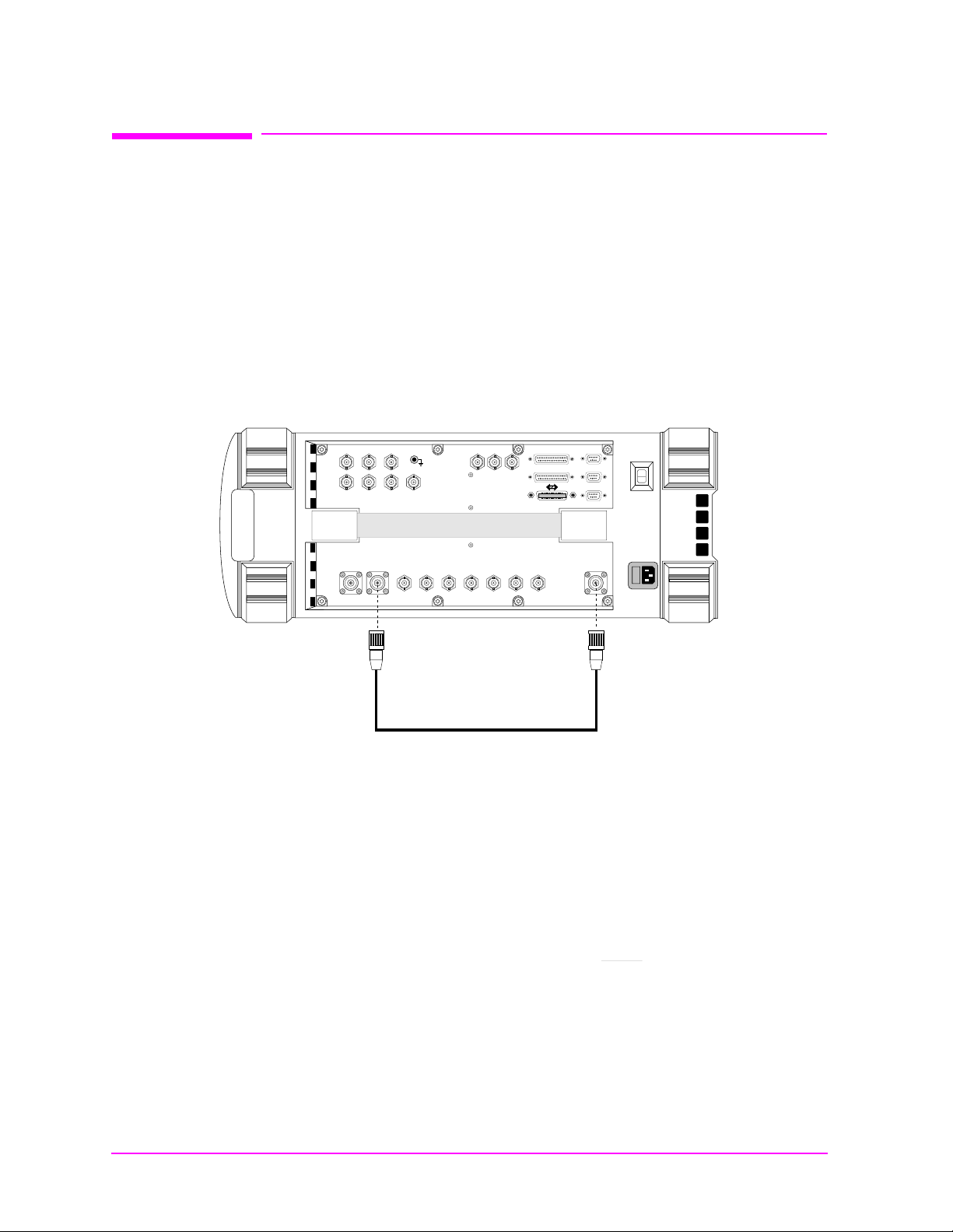
Connections for CDMA Loopback Test
Connect the Test Set in the following manner.
Figure 1-1 CDMA Loopback Test Connections
AUDIO OUT
AUDIO IN
HI LO
MODULATION
AUDIO
EXT SCOPE
OUTPUT
VIDEO
TRIG IN
OUT
16X
CHIP CLOCK
CHIP CLOCK
1.2288
19.6608
MHz OUT
MHz OUT
INPUT
MONITOR
ANT IN DUPLEX
DUPLEX OUT
Get Started with the Test Set
1. Plug in the Test Set.
2. Turn on the Test Set (or press
ANALYZER screen will be displayed.
BASEBAND OUT
QI
SYNC IN
EVEN
FRAME
TRIG/QUALIN10 MHz
SECOND
CLOCK
IN
REF OUT
REF IN
PARALLEL PORT
PARALLEL PORT
SERIA PORT
SERIA PORT
SERIA PORT
RF IN/OUT
RF IN/OUT
Preset) if it is already on. The CDMA
26 Chapter 1
3. Press the
4. Select RF Display , and set the field to Freq
Inst Config key.
.
5. Verify your con nections. See “Connec tions f or CDMA Loopback Test”
on page 26.
Page 27
Getting Started with CDMA Test
Main Menu
Display a CDMA Signal (Loopback Test)
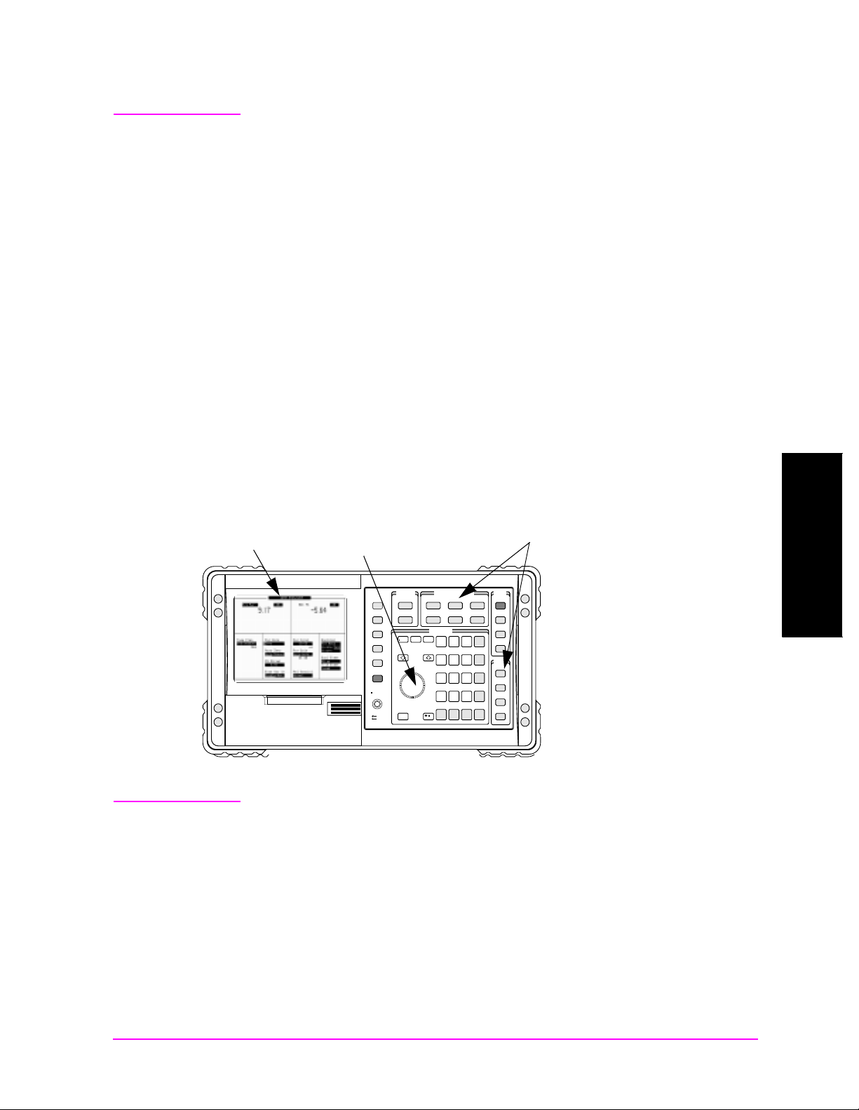
NOTE Here are so me t ips for selecting screens and fields:
• Rotate the knob to move the cursor around the screen. Reverse video
boxes indicate fields that can be selected. Press the knob to make
selections.
• A selected fi eld has a b linking doubl e arro w cursor >>. The arr ows go
away and blinking stops when the field is not selected.
• To change settings in a field on the screen, push the knob, or press
the
Enter key.
• The measurement screen is changed using the titlebar at the top of
the screen and the cursor control knob, the
GENERATOR/ANALYZER keys, or the UTILS keys.
• Use the top row of the GENERATOR/ANALYZER keys to move
around in the CDMA screens.
Figure 1-2 Using the cursor-con trol Knob or Screen Keys
Titlebar
Push the kno b to
make a selection .
Rotat e the knob
to move the
cursor, or change
settings.
USER
k1’
USER
Menu
k1
k1’
Menu
k1
k2’
Pause/
k2
Continue
k2’
Pause/
k2
Continue
k3’
k3
Ref Set
k3’
Incr
k3
10
Ref Set
k4’
Incr
10
k4
k4’
Lo Limit
k4
Release
Lo Limit
k5
Release
k5
Push to Select
Push to Select
Shift
Shift
Out of Lock
Out of Lock
Cancel
Volume
Cancel
Squelch
Volume
Squelch
Press one of the
Getting Started with CDMA
GENERATOR/ANALYZER or
UTILS keys for a shortcut to
the measurement or
configura tio n sc re e ns.
GENERATOR/ ANALYZERSOFTWARE
GENERATOR/ ANALYZERSOFTWARE
CDMA
CDMA
Gen
Anl
CDMA
CDMA
Gen
Anl
AF Anl ScopeReset
RF
RF
Gen
Anl
AF Anl ScopeReset
RF
RF
Gen
Anl
DATA ENTRY
Avg
Meter
Incr
Incr
DATA ENTRY
x 10
Set
8
7
Avg
Meter
Incr
Incr
x 10
Set
8
7
F
E
Hi limit
5
4
F
E
Hi limit
5
4
C
B
C
B
2
1
2
1
A EEX
A EEX
.
0
.
0
No
Yes
ppm
On/Off
No
Yes
W
ppm
On/Off
W
STATE
STATE
Code
Preset
Dom
Code
Preset
Meas
Dom
Reset
Spec
Hold
Meas
Anl
Reset
Spec
Hold
Anl
Save
Recall
Save
Enter
Recall
9
ADRS
Enter
9
Local
ADRS
dB
Local
GHz
dBm
dB
6
GHz
UTILS
dBm
6
UTILS
D
%
Prev
MHz
V
D
%
3
Prev
MHz
Printer
V
3
Config
Printer
Print
Config
s
Print
kHz
s
mV
I/O
+/-
kHz
Config
mV
I/O
+/-
Inst
Config
Config
Inst
Config
mW
ms
Error
Hz
%D
Message
mW
ms
V
dBV
Error
Hz
%D
Help
Message
V
dBV
Help
Chapter 1
Test
Chapter 1 27
Page 28
Getting Started with CDMA Test
Main Menu
Display a CDMA Signal (Loopback Test)
Generate a CDMA Signal
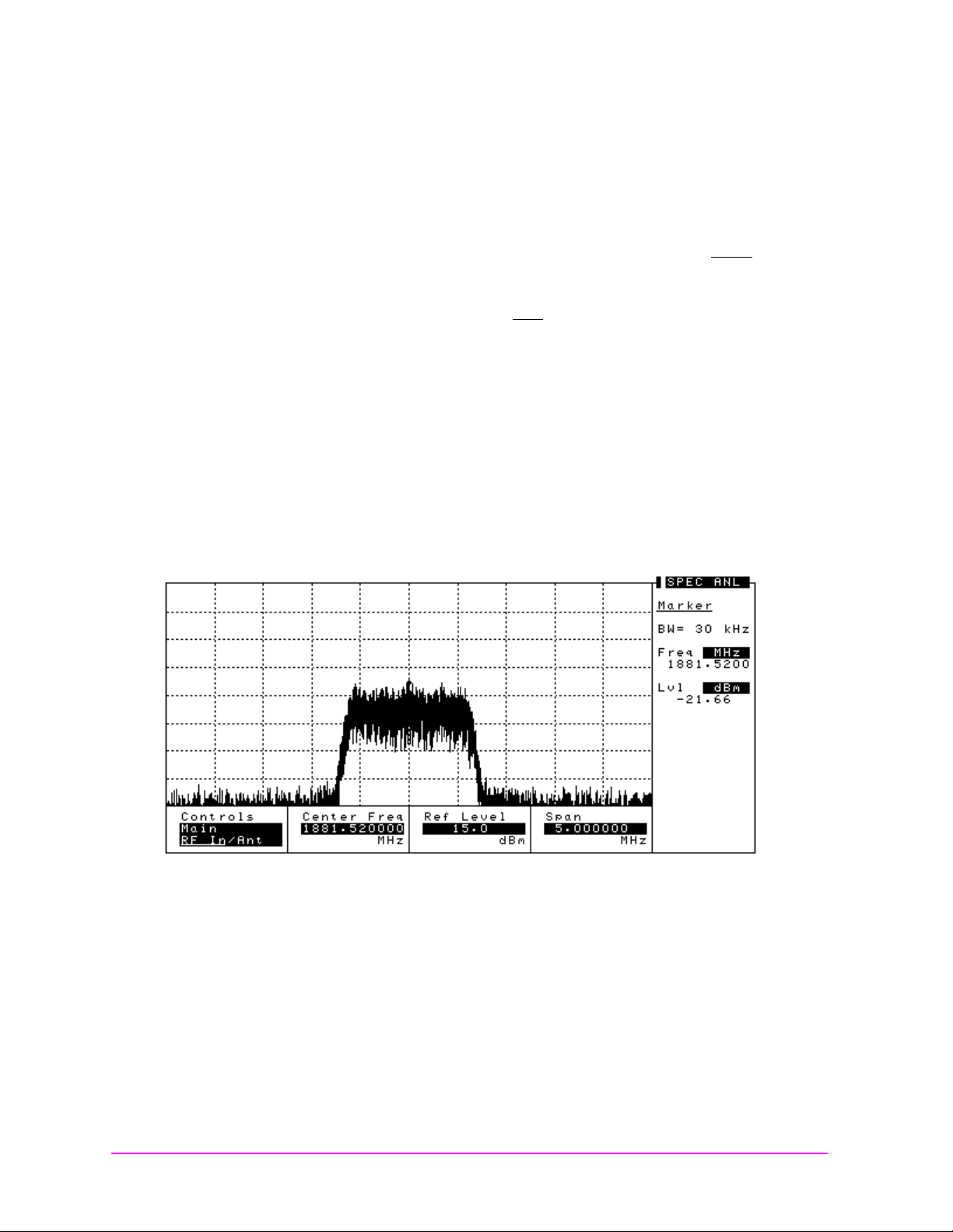
1. P ress the CDMA Gen key to go to the CDMA GENERATOR screen.
2. Select RF Gen Freq and use the keypad to set the frequency to
1881.52 MHz.
3. Select Output Port and verify that the port is set to Dupl
4. Select Amplitude and set the amplitude to −10 dB m .
5. Select Gen Dir and set it to Fwd
Display a CDMA Signal
1. P ress the CDMA Anl key to go to the CDMA ANALYZER screen.
2. Select Tune Freq and use the keypad to set the frequency to
1881.52 MHz.
3. P ress the
4. T he CDMA signal should be displayed.
Figure 1-3 CDMA Loopback Signal
Spec Anl key to go to the SPECTRUM ANALYZER screen.
.
.
What to Do Next
28 Chapter 1
Congratulations! You are now ready to begin testing your CDMA Base
Station. Proceed to Chapter 2, “Testing CDMA Base Stations.”
Page 29

2 Testing CDMA Base Stations
Main Menu
This chapter explains how to test CDMA Base Stations with the
HP 8935 Test Set. For information on performing other tasks with the
Test Set, see "Which Document is Required?" on page 18.
Testing CDMA Base Stations
Chapter 2
29
Page 30

Testing CDMA Base Stations
Main Menu
Tests That You Can Perform with the Test Set
Tests That You Can Perform with the Test Set
This Test Set is designed to perform tests you would normally use in
the setup, commissioning, and maintenance of a CDMA base station.
These tests are listed below. For other utility procedures of the Test
Set, see Chapter 3, “Utility Procedures,” on page 53.
• General
• "Setup and Configuration" on page 31
• Transmitter Tests (TX tests)
• "Average Power" on page 37
• "Channel Power" on page 40
• Frequency Error: see "Rho (Modulation Quality)" on page 49
• Carrier Feedthrough: see "Rho (Modulation Quality)" on page 49
• Time Offset: see "Rho (Modulation Quality)" on page 49
• "Rho (Modulation Quality)" on page 49
• Code Domain Phase: see "Code Domain Testing" on page 43
• Code Domain Power: see "Code Domain Testing" on page 43
• Code Domain Timing: see "Code Domain Testing" on page 43
• "Transmit Spectrum" on page 51
• Receiver Tests (RX Tests)
Receiver Tests typically require the Base Station to report FER
(Frame Error Rate), and otherwise communicate with the Test Set.
This information varies between Base Station manufacturers.
Receiver Tests made with this Test Set are performed within HP
software. See your local sales representative for available software
for your Base Stations.
30 Chapter 2
Page 31

Setup and Configuration
Main Menu
How you set up your Test Set will depend, of course, on the device you
are testing. However, there are several parameter s that are c ommon to
most setups. These are described in the following sections.
• "Connections Between the Test Set and the Device Under Test
(DUT)" on page 32
• "Configuring the Test Set with Your Base Station’s Information" on
page 33
• "Saving and Recalling Instrument Setups" on page 36
Testing CDMA Base Stations
Setup and Configuration
Chapter 2 31
Testing CDMA Base Stations
Chapter 2
Page 32
Testing CDMA Base Stations
Main Menu
Setup and Configurati on
Connections Between the Test Set and the Devi ce Unde r Test
(DUT)
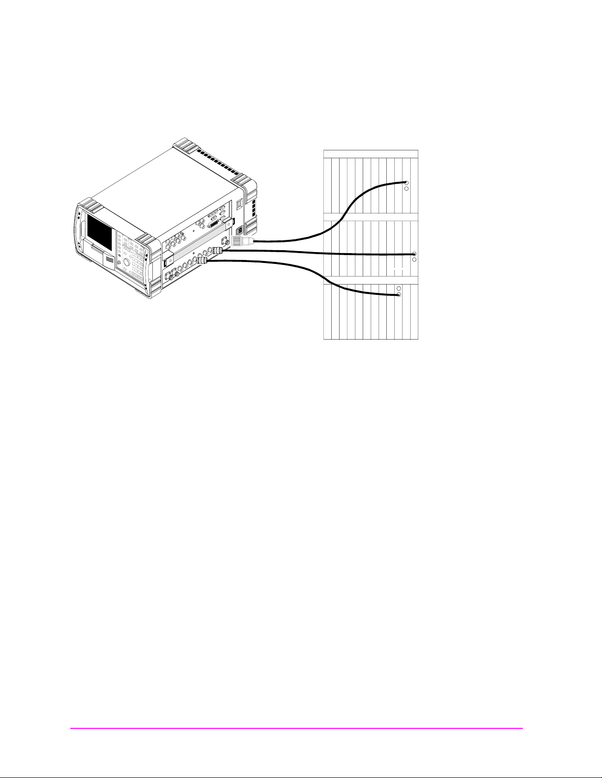
Figure 2-1 Connections for Testing a CDMA Base Station
CDMA Radio Shelves
Base Stat io n’ s
Antenna Test Port
RF IN/OUT
REF IN
SYNC IN EVEN SEC
domino30.eps
Base Station Reference Clock
(typically 10 MHz or
19.6608 MHz)
Even-Second Clock
Synchronizing Your Base Station to the Test Set
The RF signal is the signal you are testing. It typically comes from the
Base Station’s Antenna Test Port.
The Even-Second clock is used for the Time Offset measurement.
The REF IN is used for both the Time Offset and the Frequency Error
measurements. Several different signals are available, but typically
this signal is either 10 MHz or 19.6608 MHz (16x Chip Clock).
32 Chapter 2
Page 33

Testing CDMA Base Stations
Main Menu
Setup and Configuration
Configuring the Test Set with Your Base Stati on’s Info rma tio n
When you are starting to test a Base Station with the Test Set, you
must supply information about the Base Station to the Test Set.
1. Make connections to your Base Station as shown in Figure 2-1,
"Connections for Testing a CDMA Base Station," on page 32.
If you have a low level signal, you may want to use the ANT IN port
instead of the RF IN/OUT port. See "Choosing Between RF In/Out,
Antenna and Duplex Ports" on page 34.
2. Press
Preset or turn on the Test Set.
3. Select RF Channel in the CDMA ANALYZER screen. The RF signal
can be displayed either by Channel number or Frequency. See
“Changing Between Channel Mode and Frequency Mode” on page
55.
4. Enter the channel number (or frequency) of your base station.
5. Press th e
Inst Config key to go to the INSTRUMENT CONFIGURE
screen.
6. Select Ext Ref In. This is the reference signal your Base Station
provides to synchronize with the Test Set.
7. Select the reference frequency of your Base Station. Typical values
are 10 MHz or 16x the chip clock (19.6608 MHz).
8. Select Ref Select and choose either Auto, Internal or
External. Auto allows the Test Set to switch between Internal or
External References, base d on pres enc e of the Ex ter nal s ig nal a t the
Ref In port. Internal or External select either the internal or
external reference signals.
9. Press the
Spec Anl key to display the spectrum analyzer. This will give
you a visual confirmation of your signal.
Testing CDMA Base Stations
Chapter 2
Chapter 2 33
Page 34

Testing CDMA Base Stations
Main Menu
Setup and Configurati on
Choosing Between RF In/Out, Antenna and Duplex Ports
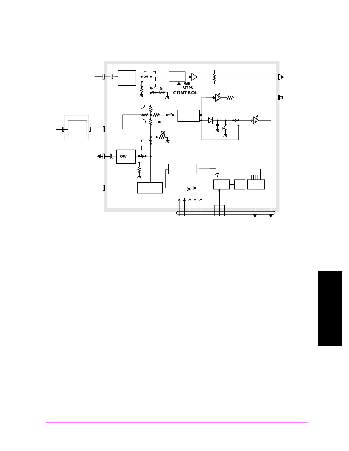
For testing input signals, you can choose between RF IN/OUT and ANT
IN. For generating signals, you can choose between RF IN/OUT and
DUPLE X OUT.
The RF IN/OUT port is for measuring transmitter signals. It has the
highest allowable input power. This port is also an output port for the
internal signal generator.
The ANT IN port is used when the signal is very low (about 200 mV).
This is an input only. It is frequently used for off-the-air measurements.
The DUPLEX OUT is the output of the signal generator. It is typically
used to test receivers and as a calibration source.
The input port is chosen by selecting the Input Port field in the
CDMA ANALYZER screen. Note that the Input Por t c annot be sel ec ted
while the Average Power measurement is displayed, since that
measurement can only be made on the RF IN/OUT port.
The output port is chosen by selecting the Output Port field in the
CDMA GENERATOR screen.
Refer to “Block Diagram for RF, DUPLE X , an d ANT Ports” on page 35
for more detail about the input ports.
34 Chapter 2
Page 35
Testing CDMA Base Stations
R
Main Menu
Figure 2-2 Block Diagram for RF, DUPLEX, and ANT Ports
RF I/O ASSEMBLY
Setup and Configuration
A2A130
TO RF
IN/OUT
SMA
FROM
ANTENNA
INPUT
100W
ATTENUATOR
HIGH
POWER
PAD 16dB
TO DUPLEX
SMA
OUTPUT
FROM
UPCONVERTER
J4
SMA
J3
SMA
J6
SMA
J2
SMA
OVER
POWER
PROTECT
-22dB
REVERSE
POWER
PROTECT
5dB
STEPS
50
-12dB
50
0-125dB
STEP ATTEN
50
-6db
0-35dB
ATTEN
CONTROL
Zeroing
Switch
ATTENUATOR
DRIVE LOGIC
D"
34%03
POWER
DETECTOR
4V PK
+5V
-12V
+12V
+15V
GND
3dB
SERIAL
I.O.
DATA
CLOCK
50
RIBBON
EN/I
CAL
ROM
ANALOG
MUX
J5
CONVERTE
SMA
J7
SMB
Avg Pwr
TX POWER
TO
DOWN-
DET_OUT
TO
RCV_DSP
Chapter 2 35
Testing CDMA Base Stations
Chapter 2
Page 36

Testing CDMA Base Stations
Main Menu
Setup and Configurati on
Saving and Recal li ng Instr ument Setups
The SAVE and RECALL functions allow you to store different
instrument setups and retrieve them later, eliminating the task of
re-configuring the Test Set. You can save these setups to any of the
following media: Internal Memory, an External PCMCIA card, or an
External RAM card.
To Save an Instrument Setup
1. If you want to select the Save medium, see "To Choose the
Save/Recall Location".
2. Ma ke any changes to the instrument that you want to save in a
register.
3. P ress and release the
Shift key then the Recall key to access the SAVE
function.
4. Use the
DATA keys or the Save menu to enter the register’s name.
To Recall an Instrument Setup
1. If you want to select the Save medium, see "To Choose the
Save/Recall Location".
2. P ress the
Recall key.
3. U se the knob to select the desired setup to be recalled from the
Recall menu.
To Choose the Save/Recall Location
1. P ress and release the Shift key then the Inst Config key to display the
I/O CONFIGURE screen.
2. Select the Save/Recall field.
3. Select the desired Save medium (Internal, Card, RAM).
36 Chapter 2
Page 37

Testing CDMA Base Stations
Main Menu
Average Power
Average Power
Average power measures the average power of full bandwidth of the
received signal. To measure the power only in a single 1.23 MHz CDMA
channel, see "Channel Power" on page 40.
This measurement is made only at the RF IN/OUT port. It can be
measured while the Base Station is active.
Prerequisites
You will need to do the following before measuring Average Power:
❏ Connect your signal to the RF IN/OUT port of the Test Set, and
connect the reference signal to the REF IN port.
❏ Know the channel number or frequency of your transmitter.
CAUTION Overpower Damage — Refer to the Test Set’s side panel for maximum
input power level. Exceeding this level can cause permanent
instrum e nt damage.
Procedure
NOTE You can zero the power meter with the Pwr Zero field to ensure the
greatest accuracy. By default, however, the power meter is
automatically zeroed.
1. Press th e
2. Zero the power meter if necessary. Select Pwr Zero to zero the
meter.
3. Select RF Channel or Tune Freq, depending on whether your
channels are selected by channel number or by frequency.
4. Enter the channel number or RF frequency of your transmitter. This
ensures that you will have the correct calibration factor for the
power measurement.
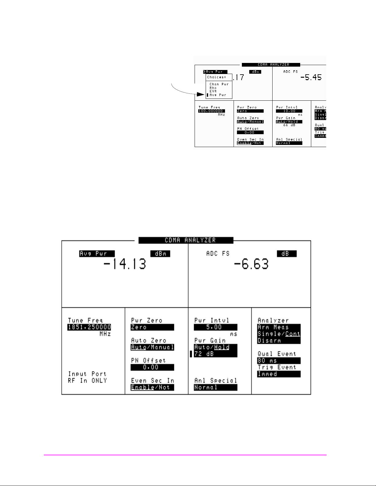
5. Select the measurement on the left side of the display (default is Avg
Pwr).
6. Select Avg Pwr from the list of choices. Now the Average Power
measurement is displayed.
CDMA Anl key to go to the CDMA ANALYZER screen.
Testing CDMA Base Stations
Chapter 2
Chapter 2 37
Page 38
Testing CDMA Base Stations
Main Menu
Average Power
Figure 2-3 Average Power Measurement List of Choices
Average Power
list of choices
7. Set the Pwr Intvl to your desired averaging time. A higher time
produces a more accurate result. Maximum value is 26.66
milliseconds.
8. T he Average power should be displayed.
Results
Figure 2-4 Average Power Measurement Results
38 Chapter 2
Page 39

Notes
Main Menu
You can control the time interval of the av er aging by c hang ing the Pwr
Intvl. Default is 5 milliseconds.
You should enter the channel number or center frequency of your
transmitter signal, since the measurement is calibrated based on that
frequency.
NOTE What is ADC FS?
ADC FS (Analog to Digital Converter Full Scale) is an indicator which
shows how close the measured power is to the maximum allowed input
power to the internal Analog-to-Digital converter (ADC).
For all measurements except Average Power, ADC FS should be in the
range of −1 to −20 dB.
For the Average Power measurement, the range is −1 to −10 dB.
Testing CDMA Base Stations
Average Power
Chapter 2 39
Testing CDMA Base Stations
Chapter 2
Page 40

Testing CDMA Base Stations
Main Menu
Channel Power
Channel Power
Channel Power measures the power in the 1 .23 MHz band of the c hosen
CDMA channel. This measurement can be made on an acti ve site (i f you
are measuring at an RF test port). This measurement is particularly
useful if you are measuring power in the presence of other signals.
Prerequisites
You will need to do the following before measuring Channel Power:
❏ Know the channel number or frequency of your transmitter.
❏ To maximize the accuracy of the Channel Power measurement,
calibrate it as needed. Conditions for calibration are:
Channel Pow er Calibration Conditions
• Whenever a 5°C ambient temperature change has occurred
• Whenever the frequency or channel number has been changed
• During or just after the 30 minute warm-up period
Channel Power Ca li br atio n Pro ce dur e
Once the prerequisites ha ve been met, use the following procedure to
calibrate Channel Power:
1. Verify that there are no cables attached to the RF IN/OUT or Ant In
ports.
2. P ress the CDMA Anl key to go to the CDMA ANALYZER screen.
3. Select RF Channel or Tune Freque nc y, depending on whether
your channels are selected by Channel Number or by frequency
4. Enter the channel number or frequency of your transmitter.
5. Select the measurement on the left side of the display. Select Chan
Pwr from the list of choices.
6. Select Calibrate to calibrate the Channel Power measurement. The
calibr at io n may require a fe w se co n ds to finish.
40 Chapter 2
Page 41

Channel Power Measurement Proced ure
Main Menu
Once the prerequisites have been met, use the following procedure to
measure Channel Power:
1. Connect your signal to the RF IN/OUT port.
Testing CDMA Base Stations
Channel Po we r
2. Press th e
CDMA Anl key to go to the CDMA ANALYZER screen.
3. Select RF Channel or Tune Frequency, depending on whether
your channels are selected by channel number or by frequency.
4. Enter the channel number or frequency of your transmitter.
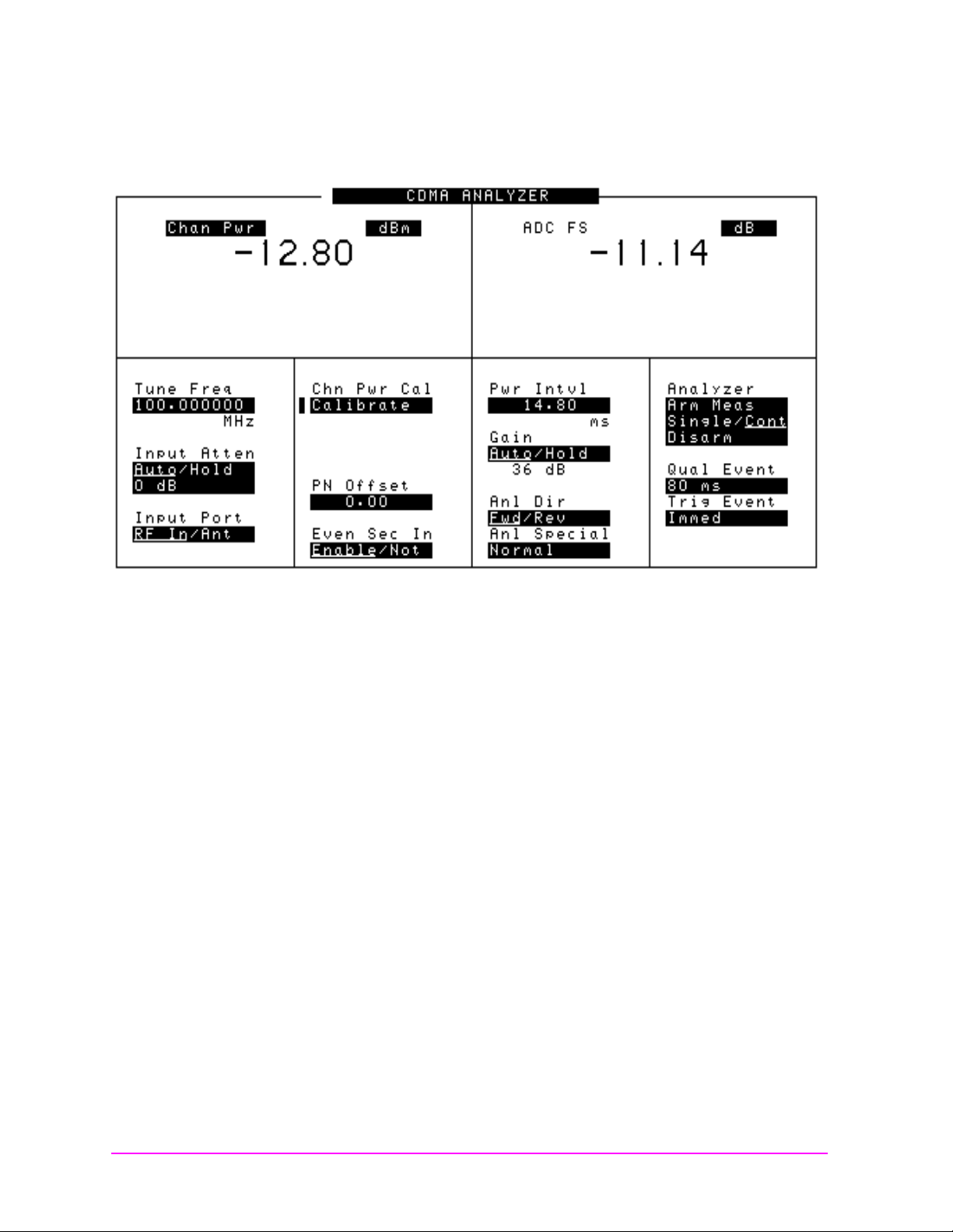
5. Select the measurement on the left side of the display. Select Chan
Pwr from the list of choices. Note that the fields change on the
CDMA ANALYZER screen.
6. The Channel Power measurement should be displayed.
NOTE What is ADC FS?
ADC FS is an indicator which shows how close the measured power is
to the maximum allowed input power to the internal Analog-to-Digital
converter (ADC).
For all measurements except Average Power, ADC FS should be in the
range of −1 to −20 dB.
For the Average Power measurement, the range is −1 to −10 dB.
Chapter 2 41
Testing CDMA Base Stations
Chapter 2
Page 42
Testing CDMA Base Stations
Main Menu
Channel Power
Results
Figure 2-5 Channel Power Measurement
Notes
This power measurement measures power in the 1.23 MHz bandwidth
of the CDMA signal, as defined by the channel nu mber or freque ncy you
have chosen. For a measurement that measures over the full input
bandwidth, see "Average Power" on page 37.
42 Chapter 2
Page 43

Code Domain Testing
Main Menu
The Code Domain Analyzer enables you to perform a suite of
measurements on your base station transmitter. These tests are
intended to be made with one or more code channels turned on. Each
code channel is represented by its Walsh code on this display.
For more detail about the Code Domain, See “Code Domain Notes” on
page 48.
Available measurements in the CODE DOMAIN ANALYZER screen
are:
• Pilot Time Toleranc e (T ime Offset)
• Frequency Offset (FrqOfs)
• Carrier Feedthrough (CarFT)(Pilot channel only)
• Code Domain Power (Power)
Testing CDMA Base Stations
Code Domain Testing
• Fast Po wer (Fast Pwr)
• Code Domain Timing (Timing)
• Code Domain Phase (Phase)
Prerequisites
You will need to do the following before making Code Domain
measurements:
❏ Connect your transmitter signal to the RF IN/OUT port of the Test
Set.
❏ Know the channel number or frequency of your transmitter.
❏ Know the PN offset for the Base Station.
CAUTION Overpower Damage — Refer to the Test Set’s side panel for maximum
input power level. Exceeding this level can cause permanent
instrum e nt damage.
Testing CDMA Base Stations
Chapter 2
Chapter 2 43
Page 44

Testing CDMA Base Stations
Main Menu
Code Domain Testing
Procedure
Use these steps to select and run the Code Domain Tests:
1. P ress the
screen.
2. U pdate the RF Chan ne l or Tune Freq field for the Base Station
being tested, if it is not already correct.
3. Select the Controls menu.
4. Select AUX from the list of choices. This will display the PN Offset
field.
5. U pdate the PN Offs et for the Base Station being tested, if it is not
already correct.
6. TmOfs, FrqOfs, and CarFT should be displayed.
7. Select the Controls menu again, and select Main.
8. Select the Measurement field and choose from Power, Fast Pwr,
Timing, or Phase.
9. Select the Controls menu again, and s elect Marker. The results for
the measurement you have chosen are displayed.
Code Dom key to go to the CODE DOMAIN ANALYZER
44 Chapter 2
Page 45
Results
Main Menu
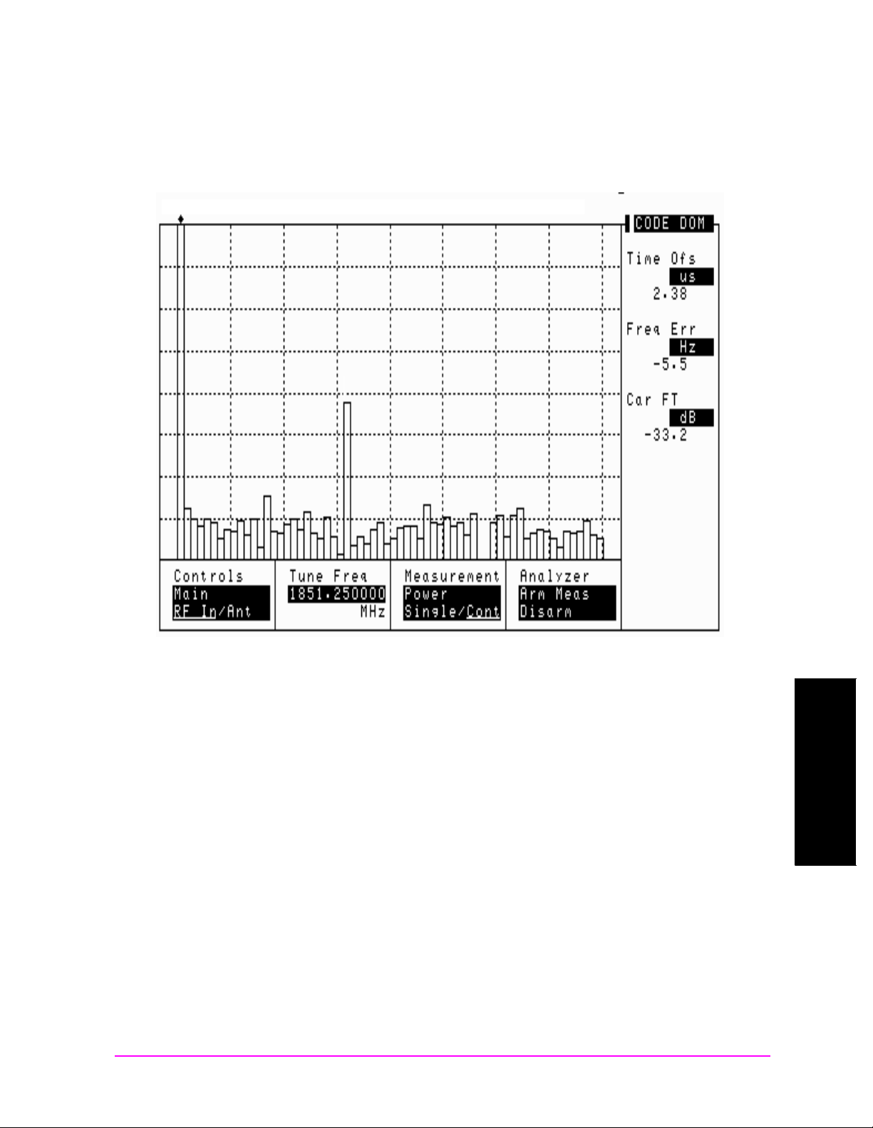
Figure 2-6 The Code Domain Analyzer Display.
Testing CDMA Base Stations
Code Domain Testing
Code Domain Measurements
Below are brief descriptions of the measurements available in the Code
Domain Analyzer.
Code Domain Power
Code Domain Power displays the power for each of the 64 Walsh
Channels, relative to the total power inside a 1.23 MHz bandwidth
centered at the Tune Frequency. Each Walsh Channel level is displayed
as an individual vertical bar. Because this is a relative measurement,
the unit of measure is always dB (not dBm or watts). This allows a
comparison of signal lev els b etw een the P il ot, Sync, Paging, and Traffic
channels.
Chapter 2 45
Testing CDMA Base Stations
Chapter 2
Page 46

Testing CDMA Base Stations
Main Menu
Code Domain Testing
Fast Power
Fast Power is a faster method of measuring Code Domain Power. A
value for Time Offset mu st be tr an sfe rred from a non-fast power
measurement before measurements begin, or when changes to the
followin g fields occur:
• Data Rate (CDMA GENERATOR screen)
• PN Offset (CDMA ANALYZER screen)
• Opt CDMA TB (INSTRUMENT CONFIGURE screen)
• Ext Ref In (INSTRUMENT CONFIGURE screen)
To transfer the Time Offset, use the following procedure.
1. Ma ke at least one of the following measurements:
• Power
• Timing
•Phase
2. Select FP Setup from the Controls menu.
3. Select Ofs Trnsfer.
4. T he offset is now transferred.
Code Domain Phase
Code Domain Phase displays the phase error for each of the 64 Walsh
channels relative to the Pilot channel. Displays above the zero reference
in the center of the screen indicate that the Walsh channel leads the
Pilot channel in phase. Displays below the zero reference in the center
of the screen indicate that the Walsh channel lags the Pilot channel in
phase. Move the marker to read the Phase for each individual channel.
Code Domain Timing
Code Domain Timing displays the time offset for each of the 64 Walsh
channels. This measurement is relative to the Pilot channel, which is
Walsh code zero. Displays above the reference indicate that the Walsh
channel is leading the Pilot channel in time. Displays below the
reference indicate that the Walsh channel is lagging the Pilot channel
in time. Move the marker to read the Timing for each individual
channel.
46 Chapter 2
Page 47
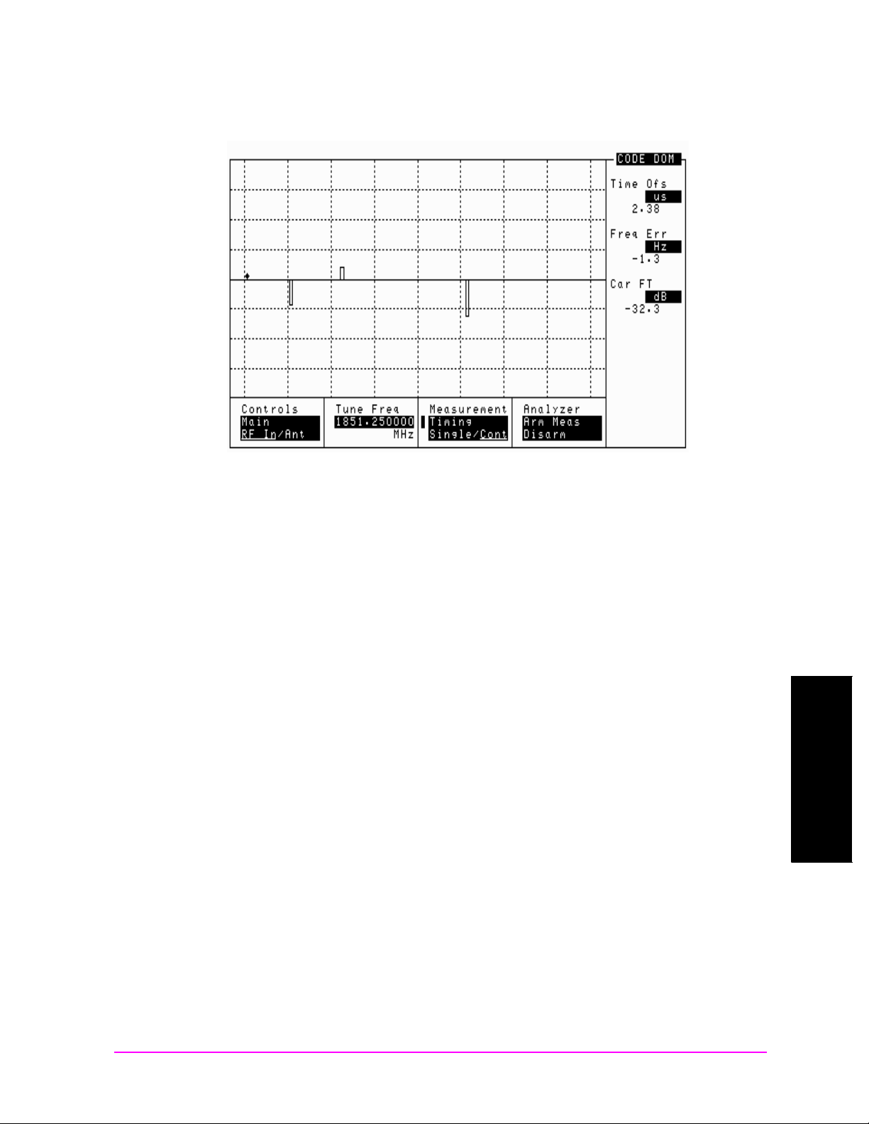
Figure 2-7 Code Domain Timing
Main Menu
Testing CDMA Base Stations
Code Domain Testing
Time Offset
Time Offset indicates how well your tr ansmitter ’s signal is time-ali gned
to system time. The displayed value takes into account the PN
Sequence Offset Index of your transmitter that i s entered on the CD MA
ANALYZER screen.
Frequen c y E r ror
Frequency error is the frequency difference between your transmitter’s
actual center frequency and the frequency (or channel) you entered.
Carrier Feedthrough
Used to measure performance of the I/Q modulator of your transmitter.
Extremely low values indicate a very good I/Q modulator. Higher values
indicate potential problems with the I/Q modulator. If Carrier
Feedthrough measures more than approximately -20 dB, there may be
problems with the Base Station. Unit of measure is dBc.
Testing CDMA Base Stations
Chapter 2
Chapter 2 47
Page 48
Testing CDMA Base Stations
Main Menu
Code Domain Testing
Code Do ma in No t e s
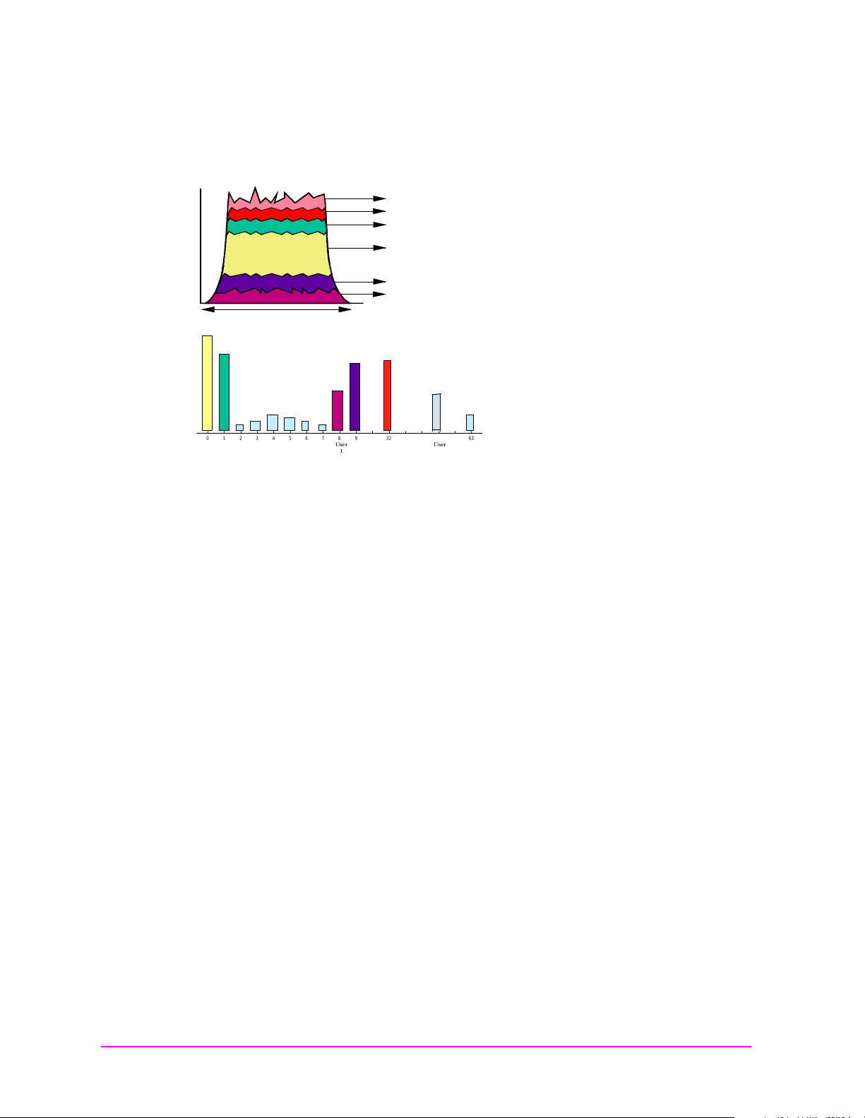
Figure 2-8 Code Domain
1.2288 MHz
freq
Other users & noise
Synch
Paging
Pilot
User #2
User #1
Frequency Domain
&REQUENCY$OMAIN
Code Domain
#ODE$OMAIN
0123456789 32 63
Pagi ng
Pilot
User
User
1
Synch
2
User
3
Walsh Code
On a spectrum analyzer, you can view the 1.23 MHz forward link
channel; it would appear as the envelope of the top figure. But how
much of the total signal, as viewed on the spectrum analyzer, is
attributed to each individual Walsh code? You cannot tell using
frequency domain analysis. This, again, requires a new measurement
method.
The measurement mode used is called "code domain analysis". In code
domain analysis, the individual Walsh codes are dec ode d and di spl ayed
individually. The c ontribution of each Walsh channel t o the tot al signal
is measured and displayed as a bar indicating the relative power in the
channel.
Figure 2-8 shows a typical display of code domain power. Note the
contribution to the total signal from the pilot, sync, and paging
channels. I n this example, there a re als o three users of traffic channels
on the forward link.
Inactive channels are important to measure, too. Ex cess power in the
inactive channels means reduced capacity in the sector.
48 Chapter 2
Page 49

Rho (Modulation Qualit y)
Main Menu
In this measurement, the modulated signal is compared to an ideal
reference waveform to determine the performance of the transmitter’s
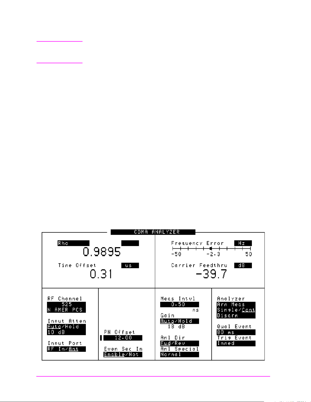
modulation circuitry. Rho values are in the range of 0 to 1. A value of 1
indicates perfect correlatio n to the reference (high modulati on quali ty ).
CDMA Base Station standards require that transmitters have rho
performance of 0.912 or higher.
With the Rho measurement, the following data is provided:
• Rho
• Frequency Error
Frequency error is the frequency difference between your
transmitter’s ac tual c enter f r eq uency a nd the frequency (or c hanne l)
you entered.
• Time Offset
Testing CDMA Base Stations
Rho (Modulation Quality)
Prerequisites
Time offset indicates how well your transmitter’s signal is
time-aligned to system time. The displayed value takes into account
the PN Sequence Offset of your transmitter.
• Carrier Feedthrough
Used to measure performance of the I/Q modulator of your
transmitter. Extremely low values indicate a very good I/Q
modulator. Higher values indicate potential problems with the I/Q
modulator. If Carrier Feedthrough measures more than
approximately −20 dB, there may be problems with the Base Station.
Unit of measure is dBc.
You will need to do the following before measuring Rho:
❏ Connect your transmitter signal to the RF IN/OUT port of the Test
Set.
❏ Connect your Even Second Clock to the Even Sec/Sync In port of the
Test Set. (Required only for Time Offset measurement)
❏ Connect your Base Station Reference signal to the REF IN port of
the Test Set.
Testing CDMA Base Stations
Chapter 2
Chapter 2 49
❏ Set up your Base Station to transmit Pilot channel only.
❏ Know the channel number or frequency of your transmitter.
❏ Know the PN offset for the Base Station.
Page 50
Testing CDMA Base Stations
Main Menu
Rho (Modulation Quality)
CAUTION Overpower Damage — Refer to the Test Set’s side panel for maximum
input power level. Exceeding this level can cause permanent
instrument damage.
Procedure
1. P ress the CDMA Anl key to go to the CDMA ANALYZER screen.
2. Select RF Channel or Tune Freque nc y, depending on whether
your channels are selected by channel number or by frequency.
3. Enter the channel number or RF frequency of your transmitter.
4. U pdate the PN Offs et for the Base Station being tested, if it is not
already correct.
5. Select the measurement on the left s ide of the display (default is Avg
Pwr).
6. Select Rho from the list of choices. Now the Rho measurement is
displayed .
7. Rho, Time Offset, Frequency Err or , a nd Ca r ri er F eedthr ough should
be displayed.
Results
Figure 2-9 Rho measurement
50 Chapter 2
Page 51
Transmi t Sp e ctrum
Main Menu
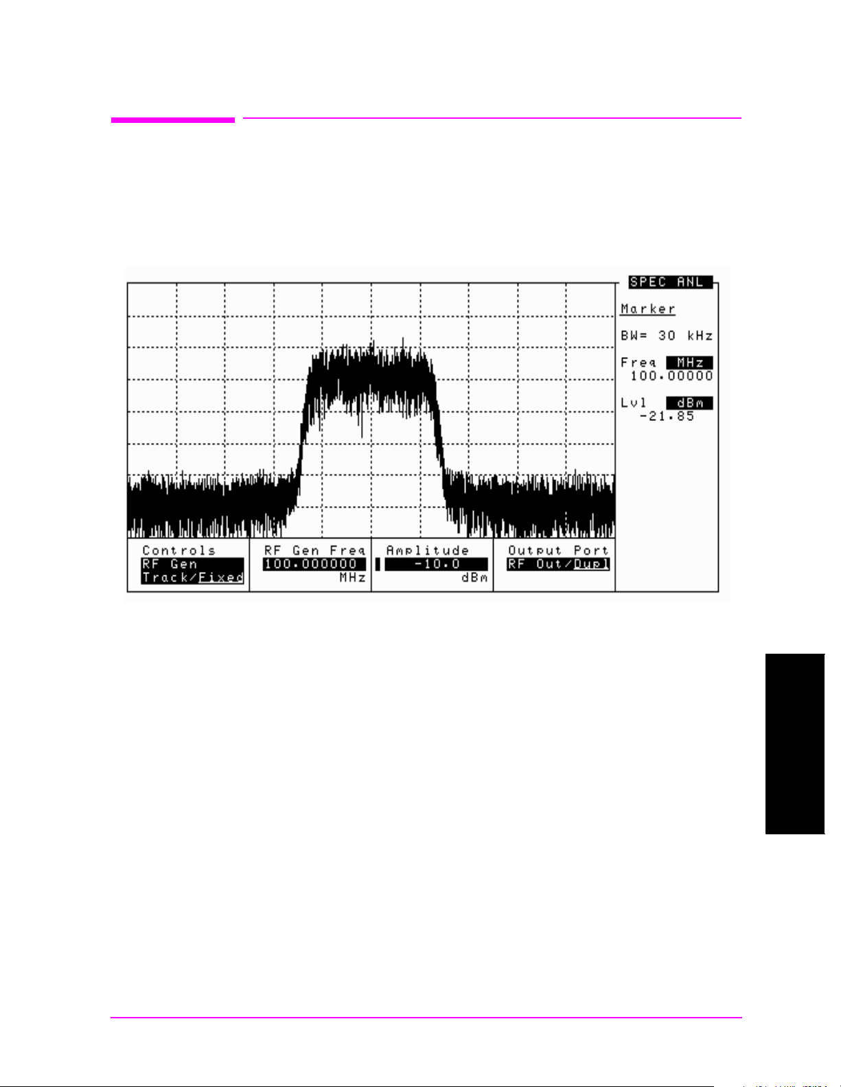
Viewing the Transmit Spectrum can give you information about your
CDMA signal and about other signals in the nearby frequencies.
Look for a CDMA signal that has the characteristic shape.
Figure 2-10 Standard CDMA Signal
Testing CDMA Base Stations
Transmit Spectrum
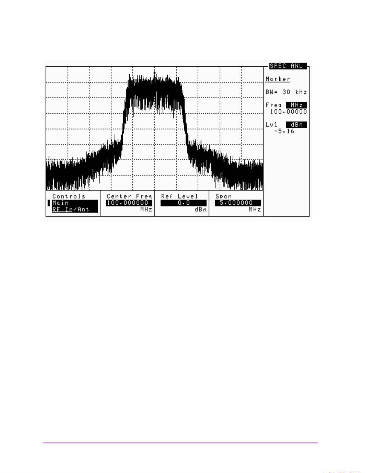
Seeing “Shoulders” on the Spectrum Analyzer display is one comm on
distortion of the CDMA shape. This problem usually occurs when there
is a problem with the power amplifier of the Base Station. The
bandwidth of the “Shoulders” is usually about twice the bandwidth of
the 1.2288 MHz CDMA signal.
Testing CDMA Base Stations
Chapter 2
Chapter 2 51
Page 52
Testing CDMA Base Stations
Main Menu
Transmit Spectrum
Figure 2-11 CDMA Signal with “Shoulders” Distortion
Prerequisites
Procedure
Sometimes the “Shoulders” also occur when there is an interfering
signal near the CDMA signal. In this case, the “Shoulders” are usually
much sma ller in bandwidt h .
You will need to do the following before you look at the transmit
spectrum:
❏ Connect your transmitter signal to either the RF IN/OUT or the
ANT IN port. You c an a lso use an a ntenna on the ANT IN port if you
want to view the signal off the air.
1. P ress the Spec Anl key to go to the SPECTRUM ANALYZER screen.
2. Select RF Channel or Tune Freque nc y, depending on whether
your desired channel is selected by channel number or by frequency.
3. Enter the channel number or frequency of your transmitter.
4. Ad just the Ref Level of the signal to better display your signal.
5. T he spectrum of your signal should be displayed. Look for
“shoulders” or interfering signals.
52 Chapter 2
Page 53

3 Utility Procedures
Main Menu
This chapter contains procedures and instructions that will help you
make the most efficient use of your Test Set.
Utility Procedu re s
Chapter 3
53
Page 54

Utility Procedures
Main Menu
Beeper
Beeper
The beeper notifies you when a message is displayed. Since a message
may be removed from the screen before you notic e it, it is better to leave
the beeper on to alert you to errors during operation.
The beeper’s volume setting is retained when the instrument is turned
off.
Beeper Control
1. P ress the Inst Config key to go to the INSTRUMENT CONFIGURE
2. Select Beeper.
3. Choose from Off, Quiet, or Loud.
screen.
54 Chapter 3
Page 55

Utility Procedures
Main Menu
Changing Between Channel Mode and Frequency Mode
Changing Betw een Channe l Mode and Freque ncy Mode
There are two ways to tune the Test Set’s Generator and Analyzer: by
channel number or by frequency. Default is channel mode, with N AMER
PCS being the default system channel standard.
Channel mode is useful when you don’t necessarily know the frequency
of the channel you are testing, but you do know the channel number
and the channel standard.
Frequency mode is useful when you are concerned about specific
frequencies. That may be when you are searching for interfering
signals, or when you want to put the Test Set in loopback mode.
• When Chan is selected, you enter the RF Generator’s and the RF
Analyzer’s channel numbers directly using the keypad or knob. You
can also choose a system channel standard.
Channel mode automatically sets the RF Generator’s and the RF
Analyzer’s frequency separation according to the system’s channel
standard.
• When Freq is selected, the RF Channel field on all screens is
replaced by frequency fields:
• RF Gen F req in the CDMA GENERATOR and RF GENERATOR
screens
• Tune Freq in the CDMA ANALYZER, RF ANALYZER, and
CODE DOMAIN ANALYZER screens
• Center Freq in the SPECTRUM ANALYZER screen
The frequency separation for frequency mode can be set in the
INSTRUMENT CONFIGURE screen.
Procedure to Change Between Channel and Frequenc y Mode s
1. Press th e Inst Config key to go to the INSTRUMENT CONFIGURE
screen.
2. Select RF Display. The value toggles between Freq
• If you selected Chan
standard fro m the RF Chan Std field.
• If you selected Freq
the RF Offset field. The frequency difference controlled by the
RF Offs et is set in the (Gen) - (Anl) field.
, you should choose your desired channel
, you can turn the RF Offset On or Off in
and Chan.
Utility Procedu re s
Chapter 3
Chapter 3 55
Page 56
Utility Procedures
Main Menu
Measuring Insertion Losses
Measuri ng In se r tio n Lo sse s
To make accurate power and receiver measurements, the signal loss
through the cables or other devices used in your test setup must be
known and entered into the Test Set’s INSTRUMENT CONFIGURE
screen to compensate for these losses.
Signal losses are measured using a built-in automated routine that
runs on the Test Set’s IBASIC controller. Losses can be calibrated at a
discrete (single) frequency or over a frequency range. This is one
routine included in a set of utility procedures called the RF TOOLS.
During the test, a calibrated signal is fed through two 6 dB
attentuators/pads (such as Mini-Circuits model NAT-6-60) and a short
type-N male-to-male cable to establish a known reference point. The
Test Set then prompts you to connect the device under test to measure
the additional loss through that device. (The pads and cable are not
part of the standard equipment shipped with the Test Set. )
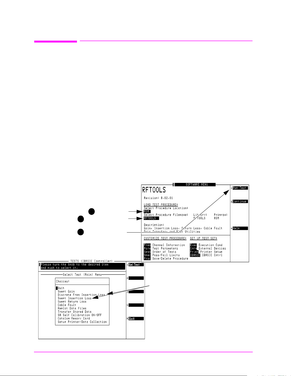
Figure 3-1 shows how to load and run the RFTOOLS routines and
select the desired insertion loss test.
Figure 3-1 Loading and Running the Insertion Loss Test
1 Select ROM
Select RFTOOLS
2
3
Select Run Test
When the screen below appears.......
...use the knob to move the cursor and
select either Discrete Freq Insertion
Loss or Swept Insertion Loss. When
run, the test prompts you to enter the
necessary test frequency information
and displays se tup dia gra ms. Make the
indicated connections and follow
instructions as you are pr ompted by the
program.
56 Chapter 3
Page 57

Memory Cards
Main Menu
The slot on the front of the Test Set is used for memory cards. The slot
is used for the following:
• Storage of Save/Recall registers
• Loading of software (either HP or self-written)
• Collecting data (only when using software)
• Upgrading firmware or software
Memory Cards and Intialization
There are several types of memory cards available, and the following
cards are used with the Test Set:
• SRAM: used for Save/Recall and data storage
Utility Procedures
Memory Cards
• Flash ROM: used when upgrading firmware
• OTP (On e Time Program mable): used for H P so ft ware
Flash ROM cannot be used for collecting data and Save/Recall.
Data cannot be loaded on Flash RAM and OTP card s with the Test Set’s
memory card slot. SRAM can be initialized with the Test Set.
Initializing SRAM Cards for Save/Recall an d Data
Collection
1. Insert the SRAM card into the slot. If the card is uninitialized, a
message will appear at the top of the displ ay.
2. Press
3. Using the knob, locate the FORMAT CARD field.
4. Select the FORMAT CARD field. A prompt will appear at the top of the
display. Pressing
Shift and IO Confg to display the I/OCONFIGURE screen.
Yes will erase and initialize the card.
Chapter 3 57
Utility Procedu re s
Chapter 3
Page 58
Utility Procedures
Main Menu
Oscilloscope
Oscilloscope
The built-in 50 kHz oscilloscope provides
• multiple triggering formats (internal and external)
• single-shot and pre-trigger viewing for single events
• full marker capability with automatic level and time readout
Time/division, volts/div ision and ve rtical of fset are di splayed and can be
changed using the front-panel knob.
Input to the Oscilloscope is provided from various sources including
direct inputs to the Audio Input and Modulation Input connectors.
Oscilloscope functions are accessed from the AF ANl and
OSCILLOSCOPE screens.
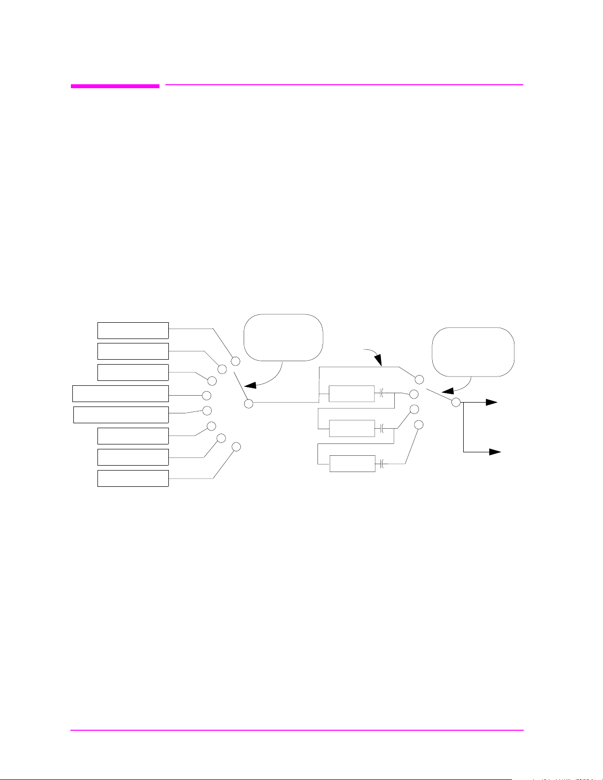
Figure 3-2 Inputs and Filters for the Oscilloscope
FM Demod
AM Demod
SSB Demo d
Audio In connector
Ext Mod connector
FM Mod
AM Mod
Audio Out
Controlled by
AF Anl In
field
Selecting the Oscil loscope ’s Input
1. Press Shift, then RF Anl to select the AF ANALYZER screen.
2. Select the AF Anl In pu t field. A list of choices should appear.
3. Select the desired input to the scope:
• FM Demod for FM dem o dula t ed audio from input signals
connected to the RF IN/OUT or ANT IN connectors.
Input
Filters
De-emp
Notch
Controlled by
Scope To
field
To
Scope
To
Audio Monitor
Out connector
58 Chapter 3
• AM Demod for AM demodulated audio from input signals
connected to the RF IN/OUT or ANT IN connectors.
• SSB Demod for SSB demodulated audio from input signals
connected to the RF IN/OUT or ANT IN connectors.
• Audio In for a signal connected to the AUDIO IN connector.
Page 59

• Ext Mod for a signal connect ed to the rear pane l MODULATION
Main Menu
INPUT connector.
• FM Mod for the FM modulated audio from the RF Gen section.
• AM Mod for the AM modulated audio from the RF Gen section.
• Audio Out for the signal present at the AUDIO OUT connector.
4. The input to the Scope is displayed on the SCOPE screen.
Selecting the Oscilloscope’s Filters
1. Press Shift, then RF Anl to select the AF ANALYZER screen.
2. Select the Scope To field. A list of choices should appear.
3. Select the desired filtering for the signal:
• Input if you want no filtering (Input is DC coupled)
• Filters to route the audio to the Oscilloscope after passing
through Filters #1 and #2. (AC coupled)
Utility Procedures
Oscilloscope
• De-emp to route the audio to the Os cilloscope after passing
through Filters #1 and #2, and the De-Emphasis circuitry.(AC
coupled)
• Notch to route the audio to the Oscilloscope after passing
through Filters #1 and #2, the De-Emphasis circuitry, and Notch
circuitry.(AC coupled)
Triggering the Oscilloscope
You can control following Triggering features of the osc illoscope:
• Trigger: external or internal
• Automated or normal triggering
• Continuous or single shot triggering
• Trigger level
• Trigger delay
The oscilloscope is triggered using the Trigger menu. Select this menu
with the following procedure:
1. Press
Shift, then Scope to go to the OSCILLOSCOPE screen.
Chapter 3 59
2. Select the Controls field, then choose Trigger from the list of
choices.
Utility Procedu re s
Chapter 3
Page 60

Utility Procedures
Main Menu
Oscilloscope
Using the Marker
The marker is used to help you make measurements with the
oscilloscope. By repositioning the marker, you can measure the level
and time.
The Marker is controlled using the Marker menu. Select this menu
with the following procedure:
1. Press
2. Select the Controls field, the choose Marker from the list of choices.
Shift, then Scope to go to the OSCILLOSCOPE screen.
60 Chapter 3
Page 61
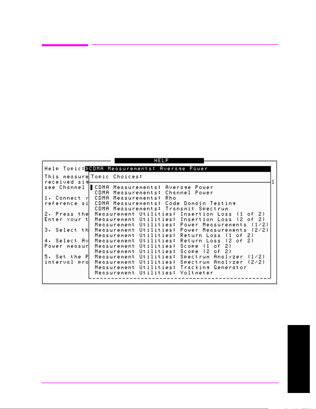
Online Help
Main Menu
Utility Procedures
Online Help
The Test Set contains help screens which briefly identify the most
commonly used features of the Test Set.
Access the Help screens by pressing the
the Help Topic of interest.
Pressing the
Prev key allows you to switch between the HELP screen
and the previous screen you had accessed. This is particularly useful
when you are following a procedure described in the HELP screen.
Help Screen Display
Figure 3-3 Help Screen Display
Help key. Use the knob to select
Chapter 3 61
Utility Procedu re s
Chapter 3
Page 62

Utility Procedures
Main Menu
Ports: HP-IB, Serial and Parallel
Ports: HP-IB, Serial and Parallel
There are three types of data ports on the Test Set: HP-IB, Serial, and
Parallel . T h ey e ach h ave specific purposes.
HP-IB Port
A special port is provided on the Test Set for IBASIC communications.
It is used to control the Test Set with an external IBASIC controller.
This port can be used with an external programming device when
writing programs, although it is also common to program the Test Set
using a serial port.
The default address of the HP-IB port is 14. This is commonly used in
IBASIC programs. An example command providing output to the port is
OUTPUT 714;”*RST” , which presets the Test Set.
It has two modes, which correspond to modes useful when
programming the Test Set. Talk&Listn is the normal mode. Use
Control only when you need to control HP-IB instruments external to
the Test Set.
Serial Ports
Controlling the HP-IB Port
1. Press Shift, then the Inst Config key to display the I/O CONFIGURE
screen.
2. Set the address of the HP-IB port with the HP-IB Adr s field.
3. U se the Mode field to set the mode to either Talk& Listn or Control.
Three serial ports are available on the Test Set. Port 9 is used for
printing, IBASIC c ontrol and d ata communications. Ports 1 0 and 11 are
used only for data communications from IBASIC.
Configuring Serial Ports
All serial ports are configured via the I/O CONFIGURE screen. Baud
Rate, Parity, Data Length, Stop Length and Flow Control are all
configured in this screen. Additionally, port 9 can be configured for
IBASIC control in this screen.
1. Press
2. Select Serial Port to choose the port you want to configure.
Shift, then I/O Config to go to the I/O CONFIGURE screen.
62 Chapter 3
3. Cha nge the settings for the port as desired.
Page 63

Utility Procedures
Main Menu
Ports: HP-IB, Serial and Parallel
NOTE Do not turn Flow Control on (set Flow Cntl to “Hardware” in the I/O
CONFIGURE screen) for the serial port until you have a device
attached to the port that can respond to the flow control
communications.
Example: Assume you have a printer attached to Serial Port 9. Power is
off to the printer. Before you start to run any IBASIC software (for
example, the RFTOOLS program), youmust make sure the printer is
attached and power is on to the printer.
Using Serial Ports for Printing
Serial Port 9 is the only serial port that can be used for printing. See
“Printing” on page 66.
1. If you want to change the serial port configuration, see “Configuring
Serial Port 9 for IBASIC Communications” on page 63. It is not
necessary to change the Serial_9 In field.
2. Press Shift, then Printer Config to display the PRINTER CONFIGURE
screen.
3. Select Printer Port. Choose Serial 9 to direct the output to
Serial Port 9.
4. Press
Print to print the screen.
Configuring Serial Port 9 for IBASIC Communica tions
The internal connection to Serial Port 9 is controlled in the I/O
CONFIGURE screen. The port has two purposes with IBASIC:
• Inst: Serial Port 9 is connected to a terminal (e.g. a PC running
Windows Terminal program). IBASIC commands are input from the
terminal and are used to control the Test Set.
• IBASIC: Serial Port 9 is c onnec ted to a device that can communicate
with an IBASIC program already running inside the Test Set.
Typically used for input/output to a PC or other device.
1. Press
Shift, then I/O Config to go to the I/O CONFIGURE screen.
2. Select Serial_ 9 In to toggle between Inst and IBASIC.
Configuring Serial Ports 1 0 a nd 11
Serial Ports 10 and 11 are only configured via IBASIC commands. See
the Programmer’s Guide for commands which control these ports.
Chapter 3 63
Utility Procedu re s
Chapter 3
Page 64

Utility Procedures
Main Menu
Ports: HP-IB, Serial and Parallel
Paralle l P or t s
There are two parallel ports on the Test Set.
Parallel Port 15 is the only pa rallel port tha t can be used for p rinting. It
can be selected in the PRINTER CONFIGURATION screen.
Both para llel ports (Port 15 and Port 16) may be u se d fo r controlling a
Base Station. The port can be put in an input or an output mode. The
data is then written or read under IBASIC control. When in either of
these modes, the printing function on Port 15 is disabled.
64 Chapter 3
Page 65

Power Mea su re m en ts
Main Menu
There are several power measurements ava ilable in this Test Set. They are listed
below, along with brief descriptions.
Average Power
CDMA ANALYZER screen. Measures the average power of the full
bandwidth of the input signal (RF IN/OUT port only). The most used
and the most accurate CDMA power measurement. Typically used
when only one CDMA signal is present. Since this measurement
measures the full bandwidth of the input signa l, if more than one s ignal
is present, the power measurement will reflect the average power of all
signals. See “Average Power” on page 37 in Chapter 2.
Channel Power
CDMA ANALYZER screen. Channel Power measures the power in the
1.23 MHz band of the chosen CDMA channel . T he f r eque ncy or c hannel
of the transmitter must first be entered in the Tune Frequency or RF
Channel field. Often used with low level signals or when making
measurements in the presence of interfering signals. Use this
measurement when there are multiple CDMA channels at the input to
the Test Set. See “Channel Power” on page 40 in Chapter 2.
Utility Procedures
Power Measurements
Code Domain Power
CODE DOMAIN screen. Measures the power for each of the 64 Walsh
Channels relative to the total power inside a 1.23 MHz bandwidth
centered at the Tune Frequency. See “Code Domain Testing” on page
43 in Chapter 2.
Fast Power
CODE DOMAIN screen. A faster method of measuring Code Domain
Power. A value for Time O ffset must be transfe rred from a non-fast
power measurement before measurements begin. See “Code Domain
Testing” on page 43 in Chapter 2.
TX Power
RF ANALYZER screen. Measures the peak power of cosine wave
signals. Used for testing FM/AM radios. Choose between Peak and
Sampled power. Do not use with CDMA, since this will result in
erroneous readings. Refer to the “HP 8935 CDMA Cellular/PCS Base
Station Test Set AMPS Base Station Tests” Manual for mo re
inform at io n.
Utility Procedu re s
Chapter 3
Chapter 3 65
Page 66

Utility Procedures
Main Menu
Printing
Printing
You can print from the Test Set via Parallel Port 15, Serial Port 9, or
the HP-IB port.
Note that data collection is not the same as printing. Data collection
can only be done from a software program.
Configuring the Test Set for Printing
1. Press Shift, then Printer Config to display the PRINTER
CONFIGURATION screen.
2. Select the Model field and choose the printer that most closely
matches your printer.
3. Select the Printer Port field and choose the port you will connect the
printer to. If necessary, use the I/O CONFIGURE screen to set up
addresses an d co mmunication modes.
a. SERIAL PORT 9: This is the uppermost serial port. Configuration
defaults are 9600, none, 8, 1, Xon/Xoff.
NOTE Do not turn Flow Control on (set Flow Cntl to “Hardware” in the I/O
CONFIGURE screen) for the serial port until you have a device
attached to the port that can respond to the flow control
communications.
Example: Assume you have a printer attached to Serial Port 9. Power is
off to the printer. Before you start to run any IBASIC software (for
example, the RFTOOLS program), youmust make sure the printe r is
attached and power is on to the printer.
b. HP-IB: The HP-IB address (HP-IB Adrs) is set to printer address
701. Enter this number as 01. Set Mode to CONTROL. (The
default add re ss 14 is reserved for an ex t er n al co n tr o lle r.)
c. PARALLEL PORT: There are two ports available. Port 15 (the
printer port) is the uppermost port.
4. Connect the proper cable to the connector you selected.
• SERIAL PORT: Use a standard NULL MODEM cable.
• HP-IB: HP-IB cable (such as HP 10833B)
66 Chapter 3
• PARALLEL PORT: Parallel cable
5. Cha nge FF (Form Feed) and Lines/Page as needed.
Page 67

Printing a Screen
Main Menu
1. Configure the Test Set for Printing.
2. Go to the screen you want to print.
Utility Procedures
Printing
3. Press th e
Hold key if you want to temporarily stop the measurement.
(Optional)
4. Press th e
Print key. Data will be sent to the printer.
5. To cancel the print, go to the PRINTER CONFIGURE screen and
select Ab or t Pr in t.
Chapter 3 67
Utility Procedu re s
Chapter 3
Page 68
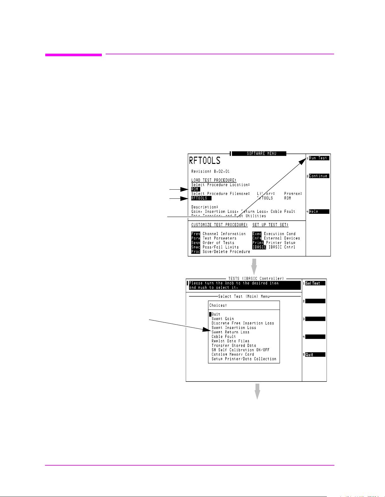
Utility Procedures
Main Menu
Measuring Swept Return Loss
Measuring Swe pt Ret urn Loss
This procedure measures the r eturn loss (VSWR) of an antenna using
an IBASIC program that is in the Test Set’s memory. An external
directional bridge must be provided (such as an Eagle RLB 150X5
Option N5A or equivalent).
Press the
the instructions illustrated on the following pages.
Figure 3-4 Loading and Running the Return Loss Program
Select RFTOOLS
Select Run Test
Menu key to access the SOFTWARE MENU screen, and follow
Select ROM
68 Chapter 3
Use the knob to move the cursor and
select Swept Return Loss.
(Next Page)
Page 69
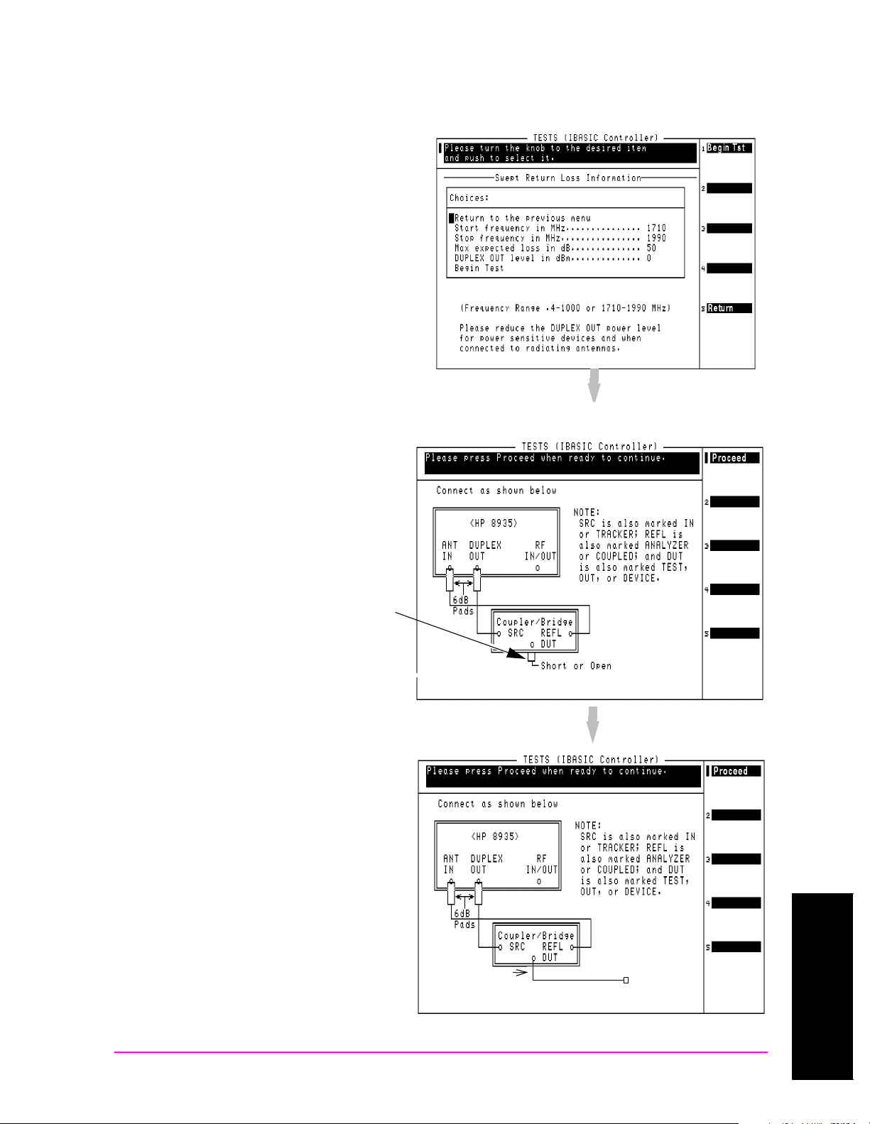
Utility Procedures
Main Menu
Measuring Swept Return Loss
Figure 3-5 Entering Swept Return Loss Measurement Information
Enter the Start an d Stop Frequency
values for the measurement.
The Max expected loss value is used to
determine the graphics scaling when the
measurement is displayed.
The DUPLEX OUT level is adj u st able
to reduce the RF level used when
measuring the loss of sensitive devices,
and to minimize the amount of
transmitted power during the test (if
necessary ).
Figure 3-6 Swept Return Loss Measurement Connections
Two 6 dB attenuators (pads), two sho rt
cables, and the return loss bridge are
used to establish a calibration
reference wit hou t th e de v ic e un de r
test connected. Press
Proceed(k1) to
continue.
As indicated by the NOTE on the
drawing, your return loss bridge may
be marked differently than shown.
When measuring the swept return lo ss
of a transmission line that is not
terminated at an antenna, terminate
the line into a 50Ω load.
After connecting your device under
test, press
Proceed(k1) to make the
measurement.
Device under test
Utility Procedu re s
Chapter 3
Termination
Chapter 3 69
Page 70
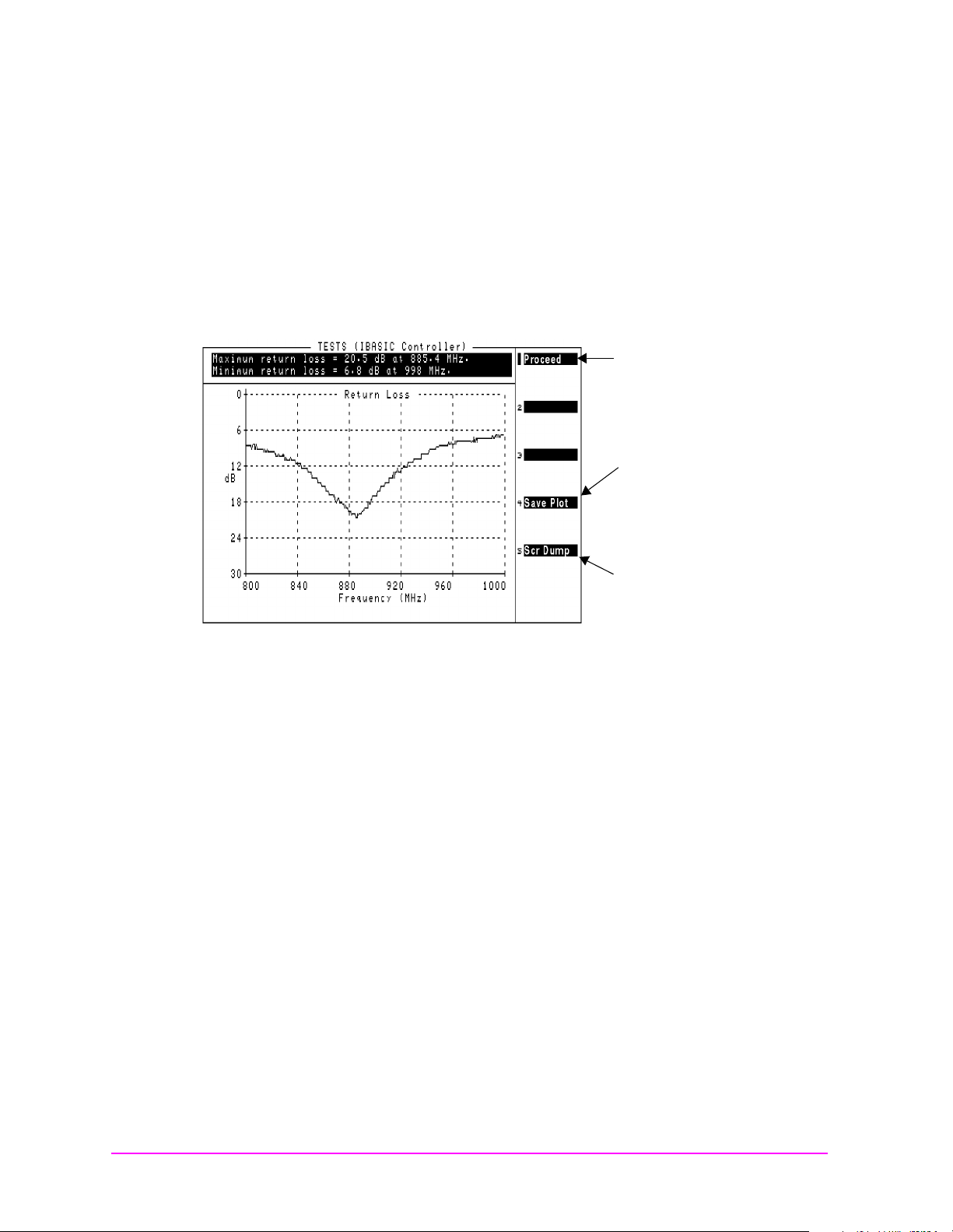
Utility Procedures
Main Menu
Measuring Swept Return Loss
The plot in Figure 3-7 is for a cellular band antenna, swept from
800 MHz to 999 MHz. The p lot ( and the text above it ) indi cates that the
maximum return loss is at 885.4 MHz. This is the point where the
antenna is radiating the maximum amount of signal being fed into it
from the return loss bridge, and therefore the Test Set is receiving the
least amount of reflected (returned) energy back.
Figure 3-7 Swept Return Loss Measurement Results
Proceed to the run the
test again or to select a
different test.
Save Plot to an
initial iz e d writeable PC
card. (See "Memory
Cards" on page 57.)
Perform a Screen
Dump to print the screen
to a connected printer.
(See "Printing" on page
66.)
70 Chapter 3
Page 71

Software: Loading
Main Menu
Instructions for loadin g software are included with th e soft ware
package. Refer to the software package’s User Guide for instructions on
how to load the software.
Utility Procedures
Software: Loading
Chapter 3 71
Utility Procedu re s
Chapter 3
Page 72

Utility Procedures
Main Menu
Tracking Generator
Tracki ng Ge ne r at or
The Tracking Generator is primarily used for measuring Return Loss
and Insertio n Loss. It also allows for quick and accurate
characterization of filters, duplexers, combiners, and RF to IF
conversions. Broadband RF devices can be characterized with single
sweeps due to the full-span sweep capability to 1 GHz. The tracking
generator also includes amplitude and frequency offset. Output from
the Tracking Generator are provided at either the side panel RF
IN/OUT or DUPLEX OUT connector.
Using the Tracking G enera tor
To measure Return Loss, see "Measuring Swept Return Loss" on page
68. To measure In sertion Loss, see "Measuring Insertion Losses" on
page 56.
Features of the Tracking Generator are listed below.
• Sweep: the start and stop frequencies of the sweep are determined
by the Spectrum Analyzer’s Main Menu. The Span determines the
band, and Center Freq defines the midpoint of the sweep.
• Offset Freq: sets the difference between the instantaneous
frequency of the Tracking Generator and the center freq uenc y of the
Spectrum Analyzer. This value can be positive or negative.
• Amplitude: sets the amplitude of the signal.
• Norm/Invert: With Norm, the Tracking Generator sweep s from low
to high frequencies. With Invert, it sweeps from high to low
frequencies.
NOTE The offset function is useful when looking at frequency translating
devices, or anytime you need to sweep around a frequency while
analyzing another. During normal operation, offset is set to “0.00”.
72 Chapter 3
Page 73
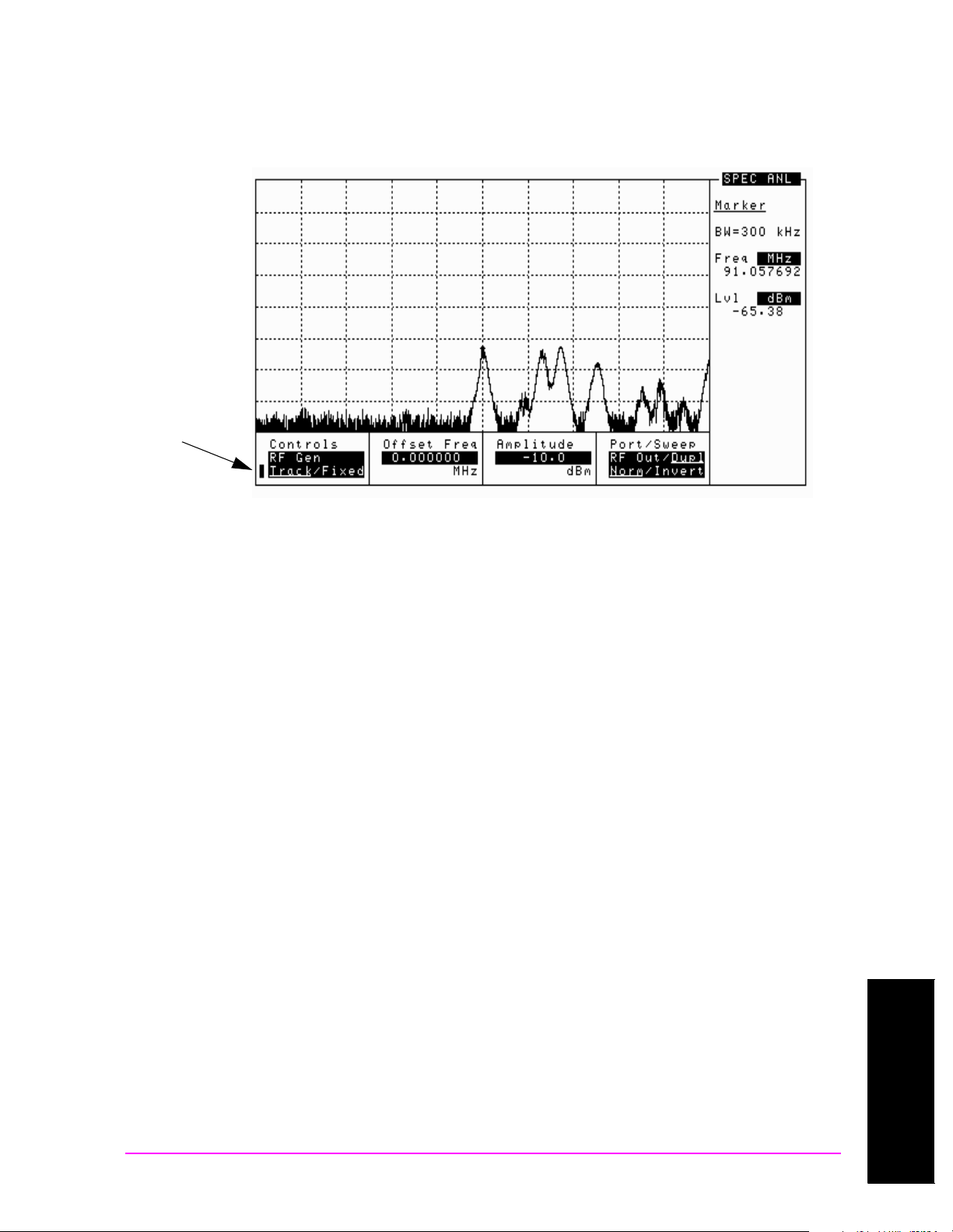
Utility Procedures
Main Menu
Tracking Generator
Figure 3-8 Spectrum Analyzer with Tracking Generator Controls
Displayed
Tracking
Generator
Controls
Chapter 3 73
Utility Procedu re s
Chapter 3
Page 74

Utility Procedures
Main Menu
User Keys
User Keys
User keys instantly access instr ume nt settings without using the knob.
You can use user keys to move quickly between fields on the same
screen, and to access field settings that are not normally available on
the screen you are using. When the user key is pressed, the cursor
instantly moves t o , an d se lects, t h e assig n ed field.
Global user keys are used to access settings that are not available on
the current screen. Three global user keys are available: k1’, k2’, and
k3’. (To use one of these keys, press
Local user keys are used to move between s etti ngs on the s c ree n that is
displayed. Five local user keys are available for each screen: k1, k2, k3,
k4, and k5. You can assign these keys yourself, or use the factory pres et
assignments.
Displaying the Pre-assigned Local User Keys
Shift, then the user key.)
1. P ress the Shift key.
2. P ress the
3. Press
Assign key (k4).
Enter. Now the factory preset keys are displayed.
Assigning a Local User Key
1. Move the cursor to the field you want to assign to a user key.
2. P ress the
3. P ress the
Shift key.
Assign key (k4).
4. P ress the user key you want to assign to the field you chose. The
number of the user key will appear beside the field when you move
the cursor.
Assigning a Global User Key
1. Move the cursor to the field you want to assign to a user key.
2. P ress the
3. P ress the
Shift key.
Assign key (k4).
74 Chapter 3
4. P ress the
Shift key.
5. P ress the user key you want to assign to the field you chose. Global
user keys are k1’, k2’, and k3’. The number of the user key does not
appear beside the field when using global user keys.
Page 75

To Release a User Key Assignment
Main Menu
Perform the same procedure for assigni ng a key, but instead of pr essing
the
Assign key (k4), press the Release key (k5).
Utility Procedures
User Keys
Chapter 3 75
Utility Procedu re s
Chapter 3
Page 76

Utility Procedures
Main Menu
Voltmeter
Voltmeter
The Voltmeter is available in the Test Set, and can measure low level
DC or AC voltages. The input to the Voltmeter is controlled by the AF
Anl In field in the AF ANALYZER screen.
CAUTION Do not exceed the rated input to the Test Set for the DC Level and AC
Level measurements. Refer to the specifications for input limits.
The connector best suited to making AC Level and DC Level
measurements is the Audio In port.
Measuring AC Level and DC Level
1. Press Shift, then AF Anl to go to the AF ANALYZER screen.
2. Select AF Anl In and choose Audio In.
3. Select Audio In Lo and choose Gnd. This sets the Audio In Lo port
to ground, which allows you to measure voltage at the Audio In Hi
port.
4. Attach a probe (for example a 1:1 oscilloscope probe) to the Audio In
Hi connector.
5. AC Level should be displayed. You may need to select AF Freq,
and choose DC Level from the list of choices, if it is not already
displayed .
76 Chapter 3
Page 77

Index
Main Menu
Index
Index
A
AC level
measuring
AC volts
measuring
ADC FS
AF Anl Input
field
AMPS testing
Analyzer
how to tune
Assembly Level Repair Manual
calibration
assigning global user keys
assigning local user keys
automatic operation
available power meas urem ents
65
average power
description
, 76
, 76
, 39
, 58
, 20
, 55
, 25
, 74
, 74
, 24
, 65
B
battery
replacing
beeper
bridge
for insertion loss
for return loss
, 21
, 54
, 56
, 68
,
C
cable
measuring insertion loss
measuring return loss
cables
for printing
HP-IB
Null Modem
Calibrate
Channel Power measurement
field
calibration
Assembly Level Repair Manual
25
Channel Power measurement
25
when you change a module
calibration offsets
call center
Europe
U.S.
, 22
Canada HP Direct
CDMA Analyzer
how to tune
CDMA Generator
channel mode
frequency mode
how to tune
CDMA Loopback Test
connections
CDMA signal
displaying
generating
screen display
CD-ROM
documentation
Cell Band CDMA testing
change battery procedure
channel mode
changing to frequency mode
when to use
channel power
description
channel standard
code domain power
fast power
congratulations
connections
CDMA Loopback Test
conventions used in his manual
17
, 66
, 66
, 66
, 25
, 25
, 22
, 22
, 55
, 55
, 55
, 55
, 26
, 26, 28
, 28
, 28
, 23
, 55
, 65
, 55
, 65
, 28
, 56
, 68
, 25
, 20
, 21
, 55
, 65
, 26
,
,
,
Index 77
Page 78

Index
Main Menu
D
DC level
measuring
DC volts
measuring
display
CDMA l oopback s i g nal
display a CDMA signal
displaying a CDMA signal
, 76
, 76
, 26
, 28
, 28
E
Eagle bridge
for insertion los s
for return loss
European Call Center
, 56
, 68
, 22
F
fast power
fields
selecting
frequency
difference
setting analyzer
setting generator
frequency mode
changing to channel m ode
how to change to channel mode
when to use
, 65
, 27
, 55
, 55
, 55
55
, 55
, 55
,
78 Index
Page 79

Index
Main Menu
Index
G
generating a CDMA signal
Generator
how to tune
Getting Help
Getting Started
global user keys
assigning
releasing
, 55
, 22
, 19
, 74
, 74
, 75
, 28
H
Help
how to get
online
screen disp l ay
hot keys
setting
HP Direct
Canada
Korea
HP-IB
port
HP-IB communications
via the serial port
HP-IB controller
internal to the Test Set
HP-IB port
controlli ng
modes
, 22
, 61
, 61
, 74
, 22
, 22
, 62
, 63
, 62
, 62
, 24
I
in this manual
insertion loss
measuring
, 56
, 17
Index 79
Page 80

Index
Main Menu
K
k1, k2, k3, k4, k5
local user keys
k1’, k2’, k3’
global user keys
knob
using
, 27
Korea HP Direct
, 74
, 74
, 22
L
loading software
local user keys
assigning
preassigned
releasing
Loopback Test
loss
measuring insertion loss
measuring return loss
, 71
, 74
, 74
, 74
, 75
, 26
, 68
, 56
M
manual operation, 24
maximizing measurement
accuracy
measurement
saving and recalling setups
measurement accuracy
maximizing
modes of the Test Set
, 25
, 25
, 24
, 36
80 Index
Page 81

Index
Main Menu
Index
O
oscilloscope
features
filter s a n d inputs
marker
selecting the filters
selecting the input
triggering
overpower damage
, 58
, 58
, 60
, 59
, 58
, 59
, 58
, 37, 43, 50
P
parallel port
input and output modes
ports 15 and 16
PCMCIA card
Flash ROM
initializing
OTP
, 57
SRAM
PCS CDMA testing
port
power
powe r m e a s u rements
preassi gn e d lo c al u se r ke y s
printi n g
probe
Product Descript ion
Programmer’s Guide
purchased software
, 57
HP-IB
, 62
HP-IB, serial, parallel
measuring AC or DC level
printing via the serial port
serial
, 62
average
channel
code domain
measurement types
measurements
TX
available
, 65
, 65
, 65
, 66
and data collection
cables
, 66
configuring the Test Set
FF (Form Feed)
how to print a screen
HP-IB
, 66
lines per page
parallel port
ports
, 66
serial port 9
via the serial port
measuring AC or DC level
, 64
, 57
, 57
, 57
, 20
, 62
, 65
, 65
, 65
, 65
, 66
, 66
, 67
, 66
, 66
, 66
, 63
, 20
, 24
, 24
, 64
, 74
, 66
, 76
, 63
, 76
R
RAM
backing up
recall
instrument setups
settings
Recall key
using
return loss
measuring
RF Analyzer
how to tune
RF cha nnel stan dard
choosing
RF Generator
how to tune
RF Offset
setting
RF Tools
measuring insertion loss
measuring return loss
, 21
, 36
, 36
, 36
, 68
, 68
, 55
, 55
, 55
, 55
, 56
, 68
Index 81
Page 82

Index
Main Menu
S
sales offices
save
instrume n t setu p s
settings
SAVE key
using
saving instrument setups
saving settings
screens
selecting
serial port
configuring
configuring for HP-IB
port 9, configuring for HP-IB
port 9, configuring for printing
ports 10 and 11
using for printing
settings
recalling
saving
setups
recalling
saving
software
loading
manufacturer-specific
purchased
RF Tools
SRAM card
initializing
systems
AMPS
CDMA
PCS CDMA
, 22
, 36
, 36
, 36
, 36
, 27
, 62
, 62
communications
communications
63
, 63
, 63
, 36
, 36
, 36
, 36
, 71
, 24
, 56, 68
, 57
, 20
, 20
, 20
, 36
, 63
, 63
, 24
T
temperature compensation
Pwr Zero
TX Pwr Zero
when to zero power
test procedure
insertion loss
return loss
Test Set
documents included
what’s in the box
time offset
and fast power
tips for selecting screens and
TMO web site
tools contain ed in the Test Set
tracking generator
,
controls disp lay
offset frequency
using
TX power
description
fields
, 72
, 25
, 25
, 56
, 68
, 27
, 22
, 65
, 65
, 73
, 72
, 23
, 72
, 25
, 23
, 25
, 20
U
U.S. Call Center
user keys
global
, 74
local
, 74
releasing
setting
Utility Procedures
, 75
, 74
, 22
, 53
82 Index
Page 83

Index
Main Menu
Index
V
voltmeter
connector
exceeding rated input
volume
controlling beep er
, 76
, 76
, 54
, 76
W
warm-up
when to zero power
web site
TMO
, 22
what to do next
What’s Included with this Test
Set
, 23
who should use theis Test Set
www.tmo.hp.com
, 25
, 28
, 22
, 21
Index 83
 Loading...