


HP 8924E CDMA Mobile Station Test Set
Introduction to Operation
Firmware Version A.02.00 and above
!
POWER
DO NOT APPLY
RF WHEN OFF
RF IN/OUT
MAX PWR
CDMA CALL CONTRO L
CDMA SCRNS
CELL
CALL
CTRL
SPECTRUM
GEN
CTRL
ANALOG SCRNS
ENCODER
RF
ANL
AF
ANL
SPEC ANL
RF
GEN
END
CALL
RANGE
RX
TEST
MSRPT
TX
TEST
DECODER
RX
TEST
ACP
TX
TEST
SCOPE
DUPLEX
CALL ANS
USER DATA
k1’
k1
k2’
k2
k3’
k3
ASSIGN
k4
RELEASE
k5
DUPLEX OUT
MAX PWR
200 mW
!
ANTENNA IN
!
6 W
FUNCTIONS
MSG
PRINTER
HELP
PRINT
DATA FUNCTIONS
REF SET
METER
INCR
INCR
: 10
SET
LO LIMIT HI LIMIT
CURSOR
CONTROL
CANCELSHIFT
I/O CONFIG CONFIG
PREV TESTS
AVG
INCR X10
PUSH TO
SELECT
INSTRUMENT STATE
ADRS
SAVE
LOCAL
RECALL
789
456
123
+
0
ON/OFF
YES
Ω
NO
%
ppm
dBµV
W
AUDIO OUTSQUELCHVOLUMEMIC/ACC
MAX
!
12 v Pk
_
HOLD
MEAS
RESET
ENTER
dB
GHz
dBm
%
MHz
V
s
kHz
mV
ms
Hz
µV
AUDIO IN
MAX
!
42 v Pk
PRESET
MEMOR
Y CARD
LOHI
HP Part No. 08924-90058
Printed in U. S. A.
August 1998
Rev. B
1

Copyright © Hewlett-Packard Company 1998
Notice
Information contained in this document is subject to change without notice.
All Rights Reserved . Reproduction, a daptation, or translation wit hout prior writ ten
permission is prohibited, except as allowed under the copyright laws.
This material may be reproduced by or for the U.S. Government pursuant to the
Copyright License under the clause at DFARS 52.227-7013 (APR 1988).
Hewlett-Packard Company
Learning Products Department
24001 E. Mission
Liberty Lake, WA 99019-9599
U.S.A.
2

Manufacturer’s Declaration
This statement is provided to comply with the requirements of
the German Sound Emission Directive, from 18 January 1991.
This product has a sound pressure emission (at the operator
position) < 70 dB(A).
• Sound Pressure Lp < 70 dB(A).
• At Operator Position.
• Normal Operation.
• According to ISO 7779:1988/EN 27779:1991 (Type Test).
Herstellerbescheinigung
Diese Information steht im Zusammenhang mit den Anforderungen der
Maschinenlärminformationsverordnung vom 18 Januar 1991.
• Schalldruckpegel Lp < 70 dB(A).
• Am Arbeitsplatz.
• Normaler Betrieb.
• Nach ISO 7779:1988/EN 27779:1991 (Typprüfung).
3

Safety
Considerations
GENERAL
This product and relat ed documen tation mu st be revie wed for fa miliar ization with
safety markings and instructions before operation.
This product has been designed and tested in accordance with IEC Publication
1010, "Safety Requirements for Electronic Measuring Apparatus," and has been
supplied in a safe condition. This instruction documentation contains information
and warnings which must be followed by the user to ensure safe operation and to
maintain the product in a safe condition.
SAFETY EARTH GROUND
A uninterruptible safety earth ground must be provided from the main power
source to the product input wiring terminals, power cord, or supplied power cord
set.
CHASSIS GROUND TERMINAL
To prevent a potential shock hazard , always conne ct the rear- panel chass is ground
terminal to earth ground when operating this instrument from a dc power source.
SAFETY SYMBOLS
Indicates instrument damage can occur if indicated operating limits are exceeded.
!
Indicates hazardous voltages.
Indicates earth (ground) terminal
WARNING
A WARNING note denotes a hazard. It calls attention to a procedure,
practice, or the like, which, if not correctly performed or adhered to, could
result in personal injury. Do not proceed beyond a WARNING sign until the
indicated conditions are fully understood and met.
CAUTION
A CAUTION note denotes a hazard. It calls attention to an operation procedure,
practice, or the like, which, if not correctly performed or adhered to, cou ld resu lt
in damage to or destruction of part or all of the product. Do not proceed beyond
an CAUTION note until the indicated conditions are fully unde rstood and met.
4

Safety Considerations for this Instrument
WARNING This product is a Safety Class I instrument (provided with a protective
earthing ground incorporated in the power cord). The mains plug shall only
be inserted in a socket outlet provided with a protective earth contact. Any
interruption of the protective conductor inside or outside of the product is
likely to make the product dangerous. Intentional in terruption is
prohibited..
Whenever it is likely that the protection has been impaired, the instrument
must be made inoperative and be secured against any unintended operation.
If this instrument is to be energized via an autotransformer (for voltage
reduction), make sure the common terminal is connected to the earth
terminal of the power source.
If this product is not used as specified, the protection provided by the
equipment could be impaired. This product must be used in a normal
condition (in which all means for protection are intact) only.
No operator serviceable parts in this product. Refer servicing to qualified
personnel. To prevent electrical shock, do not remove covers.
Servicing instructions are for use by qualified personnel only. To avoid
electrical shock, do not perform any servicing unless you are qualified to do
so.
The opening of covers or removal of parts is likely to expose dangerous
voltages. Disconnect the product from all voltage sources while it is being
opened.
Adjustments described in the manual are performed with power supplied to
the instrument while protective covers are removed. Energy available at
many points may, if contacted, result in personal inj ury.
The power cord is connected to internal capacitors that my remain live for
5 seconds after disconnecting the plug from its power supply.
For Continued protection against fire hazard, replace the line fuse(s) only
with 250 V fuse(s) or the same current rating and type (for example, normal
blow or time delay). Do not use repaired fuses or short circuited fuseholders.
5

CAUTION: Always use the three-prong ac power cord supplied with this product. Failure to ensure
adequate earth grounding by not using this cord may cause product damage.
This product is designed for use in Installation C a tegory II and Pollution Degree
2 per IEC 1010 and IEC 664 respectively.
This product has autoranging line voltage input, be sure the supply voltage is
within the specified range.
Ventilation Requirements: When installing the product in a cabinet, the
convection into and out of the product must not be restricted. The ambient
temperature (outside the cabinet) must be less than the maximum operating
temperature of the product by 4° C for every 100 watts dissipated in the cabinet.
If the total power dissipated in the cabinet is greater than 800 watts, then forced
convection must be used.
Product Markings
CE - the CE mark is a registered trademark of the European Community. A CE
mark accompanied by a year indicated the year the design was proven.
CSA - the CSA mark is a registered trademark of the Canadian Standards
Association.
6

HP 8924E
Hewett-Packard Warranty Statement for Commercial Products
Duration of
Warranty: 1 year
1. HP warrants HP hardware, accessories and supplies against defects in materials and
workmanship for the period specified above. If HP receives notice of such defects
during the warranty period, HP will, at its option, either repair or replace products
which prove to be defective. Replacement products may be either new or like-new.
2 HP warrants that HP software will not fail to execute its programming instructions, for
the period specified above, due to defects in material and workmanship wh en properly
installed and used. If HP receives notice of such defects during the warranty period, HP
will replace software media which does not execute its programming instructions due
to such defects.
3. HP does not warrant that the operation of HP products will be un interrupted or error
free. If HP is unable, within a reasonable time, to repair or replace any product to a
condition as warranted, customer will be entitled to a refund of the purchase price upon
prompt return of the product.
4 HP products may contain remanufactured parts equivalent to new in performance or
may have been subject to incidental use.
5. The warranty period begins on the date of delivery or on the date of installation if
installed by HP. If customer schedules or delays HP installation more than 30 days after
delivery, warranty begins on the 31st day from delivery.
6 Warranty does not apply to defects resulting from (a) improper or inadequate mainte-
nance or calibration, (b) software, interfac ing, parts or supplies not supplied by HP, (c)
unauthorized modification or misuse, (d) operation outside of the published environmental specifications for the product, or (e) improper site preparation or maintenance.
7 TO THE EXTENT ALLOWED BY LOCAL LAW, THE ABOVE WARRANTIES
ARE EXCLUSIVE AND NO OTHER WARRANTYOR CONDITION, WHETHER
WRITTEN OR ORAL IS EXPRESSED OR IMPLIED AND HP SPECIFICALLY
DISCLAIMS ANY IMPLIED WARRANTIES OR CONDITIONS OR MERCHANTABILITY, SATISFACTORY QUALITY, AND FITNESS FOR A PARTICULAR
PURPOSE.
8 HP will be liable for damage to tangible property per incident up to the greater of
$300,000 or the actual amount paid for the product that is the subject of the claim, and
for damages for bodily injury or death, to the extent that all such damages are determined by a court of competent jurisdiction to have been directly caused by a defective
HP product.
7

9. TO THE EXTENT ALLOWED BY LOCAL LAW, THE REMEDIES IN THIS
WARRANTY STATEMENT ARE CUSTOMER’S SOLE AND EXCLUSIVE
REMEDIES. EXCEPT AS INDICATED ABOVE, IN NO EVENT WILL HP OR ITS
SUPPLIERS BE LIABLE FOR LOSS OF DATA OR FOR DIRECT, SPECIAL,
INCIDENTAL, CONSEQUENTIAL (INCLUDING LOST PROFIT OR DATA), OR
OTHER DAMAGE, WHETHER BASED IN CONTRACT, TORT, OR
OTHERWISE.
FOR CONSUMER TRANSACTIONS IN AUSTRALIA AND NEW ZEALAND:
THE WARRANTY TERMS CONTAINED IN THIS STATEMENT, EXCEPT TO
THE EXTENT LAWFULLY PERMITTED, DO NOT EXCLUDE RESTRICT OR
MODIFY AND ARE IN ADDITION TO THE MANDATORY STATUTORY
RIGHTS APPLICABLE TO THE SALE OF THIS PRODUCT TO YOU.
8

Contents
Calibrate the Test Set 17
Table Of Contents
Calibration Procedures 18
Preset the Test Set. 20
CDMA Channel Level Calibration Procedure 21
Channel Power Measurement Calibration 23
RF Generato r Level Calibration (PC S Interface) 26
Average Power Measurement Zeroing 27
Correcting for RF Path Loss 31
Determining RF Path Loss 33
9

Contents
Set Up a Call 41
Setting Up a CDMA Call 42
Setting up a Call 43
Procedure Overview 51
Problem Solving Checklist 52
10

Contents
Mobile Station CDMA Tests 53
Table Of Contents
List of CDMA Tests 54
Rho (Transmitter Waveform Quality) 55
Minimum/Maximum Transmitter Power 57
FER (Frame Error Rate) 59
11

Contents
Mobile Station Analog Tests 65
List of Analog Tests 66
Performing a CDMA to Analog Handoff 67
Performing an Analog Call 71
Transmitter Measurements (no audio connections required) 75
Receiver Audio Distortion and Hum and Noise (requires audio connections) 78
Transmitter Audio Distortion and Hum and Noise (requires audio
connections) 83
12

Contents
Short Message Service Tests 87
Table Of Contents
List of CDMA SMS Tests 88
Sending Short Messages on the Paging/Access Channels 89
Sending Short Messages on the Traffic Channels 97
13

Contents
Authentication Tests 107
List of CDMA Authentication Tests 108
Initializing SSD to Zero 109
Updating SSD 117
Performing a Unique Challenge-Response 124
14

Contents
Protocol Logging 131
Table Of Contents
Hardware and Software Requirements 133
Connecting the Test Set to the Computer 135
Setting Up the Communications Package 137
Logging Protocol Messages 140
Control Commands for Protocol Logging 143
15

Contents
Index 149
16

1
Calibrate the Test Set
Calibrating The Test Set
Chapter 1
17

Chapter 1, Calibrate the Test Set
Calibration Procedures
Calibration Procedures
This chapter provides step-by-step procedures for performing the Test Set’s
calibration routines.
To determine when each of the following calibration procedures should be
performed, refer to the HP 8924E Users Guide, "Recommended Calibration
Procedures."
List of Procedures
If you are unfamiliar with the use of the cursor control knob, see
yourself with the CURSOR CONTROL knob." on pa ge 19
❒ CDMA Channel Level calibration - 8 minutes
❒ Channel Power Measurement calibration - 2 minutes or more
❒ RF Generator Level calibration - 15 seconds
❒ Average Power Measurement zeroing - 2 seconds
❒ RF Path Loss correction
.
"Familiarize
18

Familiarize yourself with the CURSOR CONTROL knob.
Chapter 1, Calibrate the Test Set
Calibration Procedures
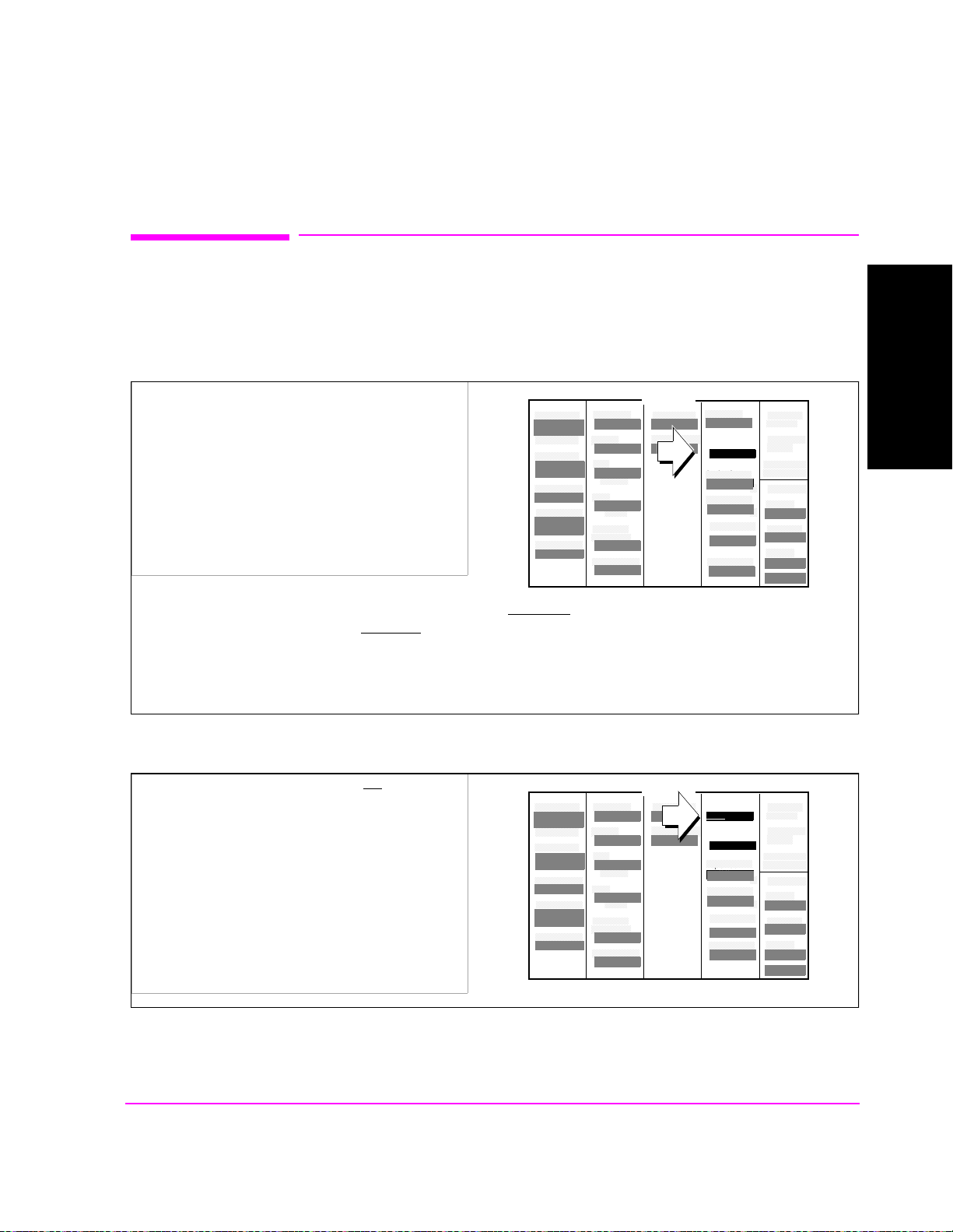
1. Position
2. Select or set
Throughout this tutorial, the terms "position," “select,” and “set” are used to
describe the interaction of the cursor (which appears as a small, lighted
rectangular box) and the fields on the screen.
Position
To position the cursor at a field, rotate the knob to move the cursor.
Select
Calibrating The Test Set
Chapter 1
To select a field, position the cursor in front of a field or menu item, and then press the
cursor-control knob.
When a field is selected, a selection may be underlined, a list of choices may be displayed, or the field may be highlighted to indicate that it is ready for a data entry. In
some cases, a message appears at the top of the display to indicate suggested actions.
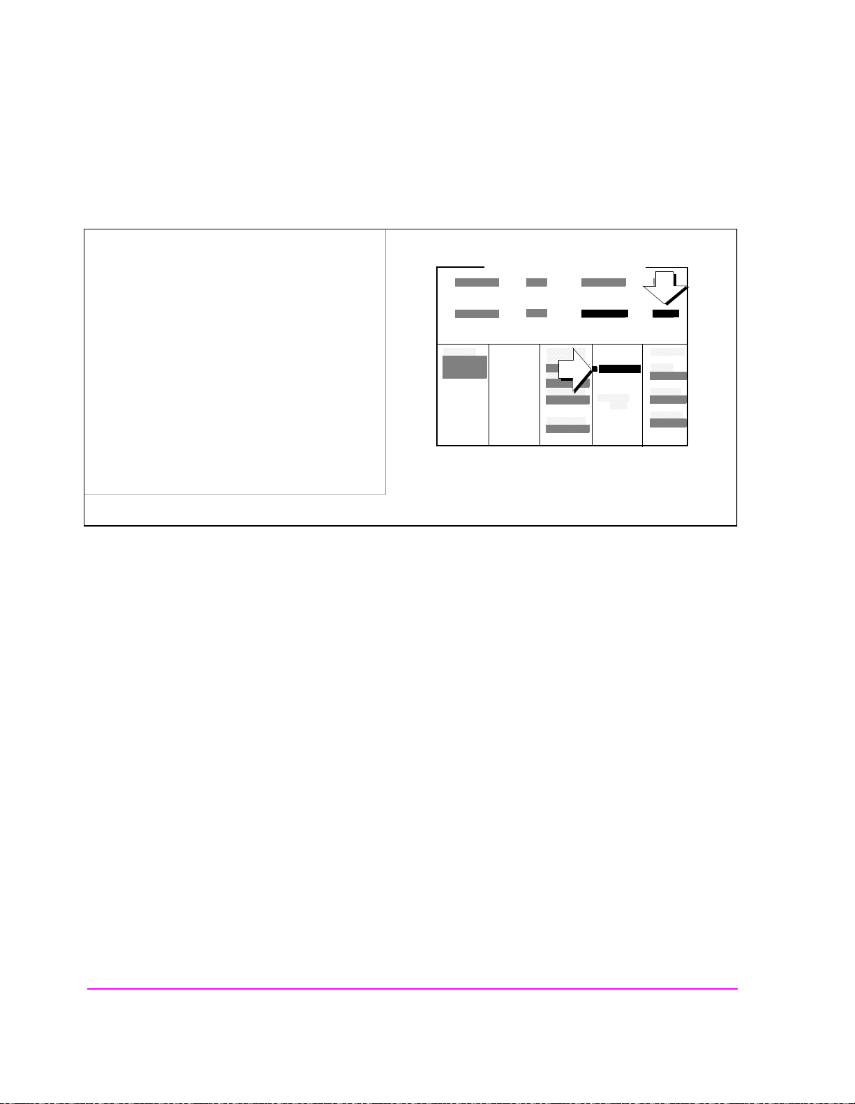
Set
To set a field, first select it, then choose a setting by either selecting from a list of
choices, underlining (such as On/Off
). or making a data entry.
If you are unfamiliar with ope rat ion of th e Test Set, se le ct sever al fie lds to se e the
what happens (rotate the cursor-control knob to move the cursor to any field and
press the knob), then press PRESET to reset the instrument.
19

Chapter 1, Calibrate the Test Set
Preset the Test Set.
Preset the Test Set.
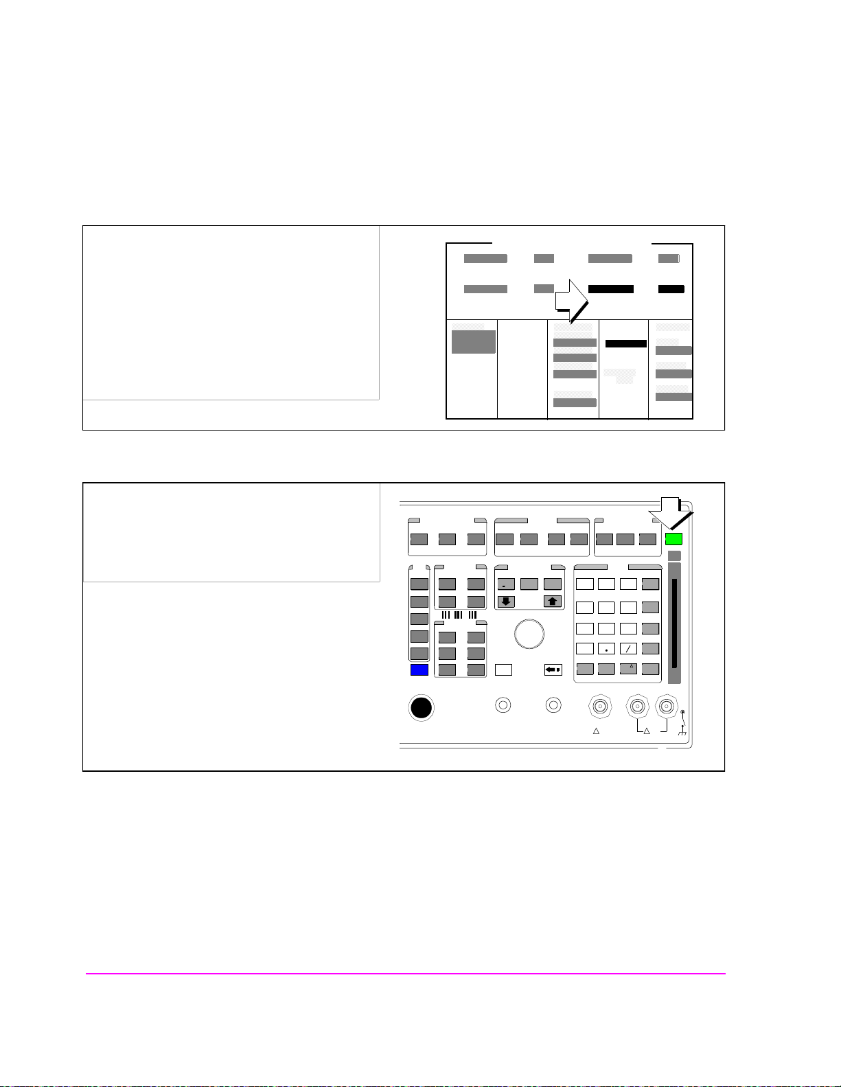
1. If the Test Set is not powered on:
a. turn on power to the PCS Interface (if one is
connected), then...
b. turn on power to the Test Set. Wait for the Test
Set to complete its power-up routine
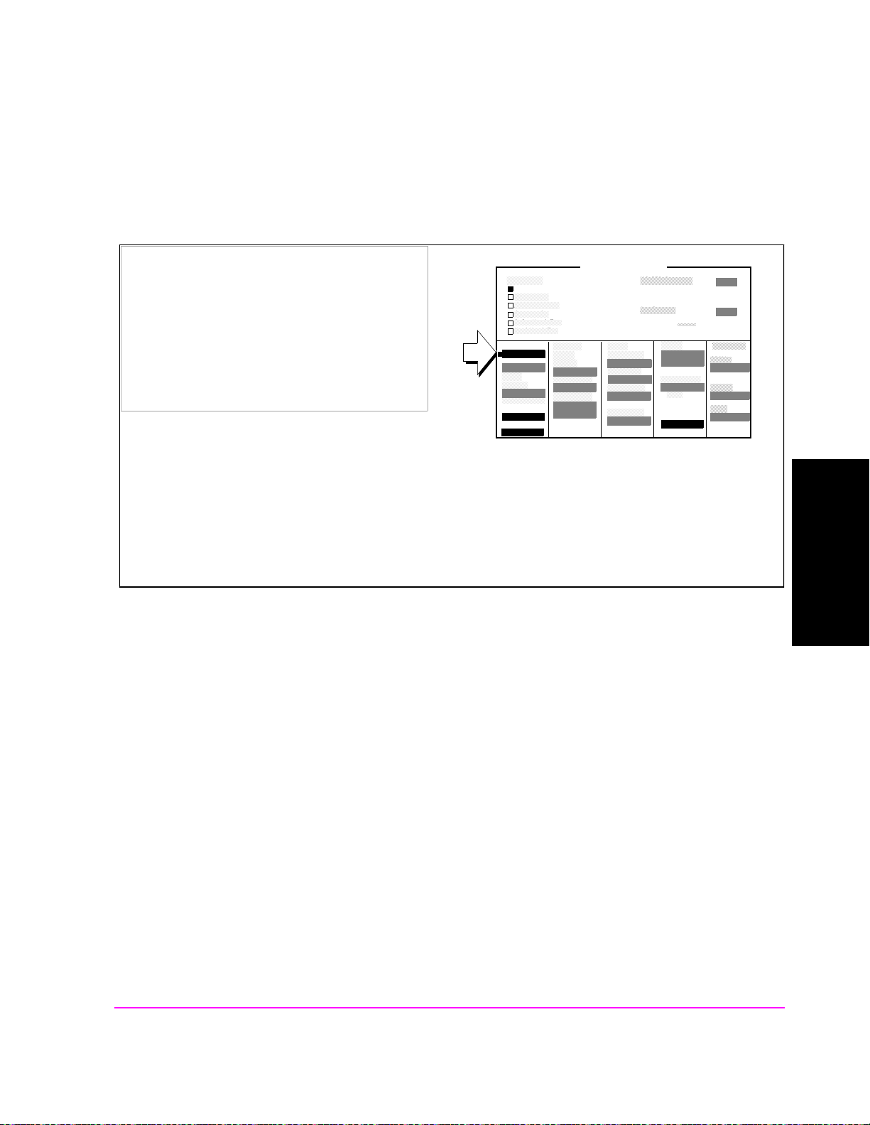
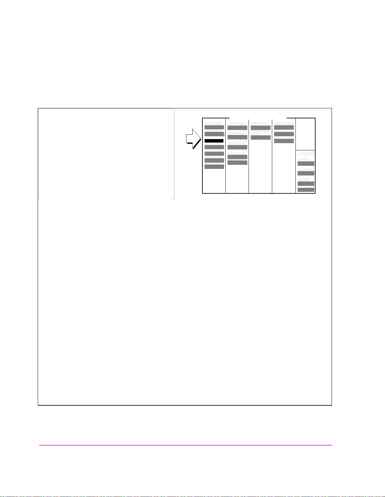
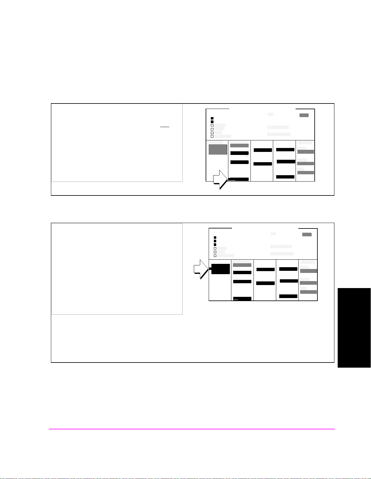
2. Press the PRESET key (to begin this procedure
in a known state).
Call Status
Transmitting
Page Sent
Access Probe
Connected
Softer Handoff
Hard Handoff
RF Channel
384
Register
Softer
Handoff
Begin/End
Answer Mode
Auto/Manual
Call Limit
None/Page
CDMA CALL CONTROL
MS FER
Report
Interval
5 frames
by # frames
On/Off
by # frames
On/Off
5
Traffic
Data Mode
Svc Opt 1
Data Type
Echo
Echo Delay
Short
Avg Power
Power Zero
MS FER Report
Avg Power
MS ID
Phone Num
5099214001
MS Database
ESN
1234
Sector A
Power
-73.0
----
dBm/BW
%
dBm
To Screen
CDMA
CALL CNTL
Analog
RX TEST
Cnfig
PRNT CNFG
Pressing the PRESET key will configure the Test Set using factory default settings, and display the CDMA
CALL CONTROL screen.
If you have the Test Set configured to operate with a PCS Interface, and you do not turn PCS Interface
power on before the Test Set, the message “PCS Interface not found. Check power, cabling or CONFIG.”
will be displayed. To correct this condition, follow the correct sequence of powering up these two units.
20

Chapter 1, Calibrate the Test Set
CDMA Channel Level Calibration Procedure
CDMA Channel Level Calibration Procedure
Approximate time: 8 minutes
1. Load the PCB_CAL procedure.
1. Press the TESTS key.
2. Select ROM from the list of choices for the
Select Procedure Location field.
3. Select PCB_CAL from the list of choices for
the Select Procedure Filename field.
2. Run the PCB_CAL Procedure.
1. Select the Run Test field.
Select Procedure Location:
ROM
Select Procedure Filename:
PCB_CAL
TESTS (Main Menu)
TESTS (Main Menu)
Calibrating The Test Set
Chapter 1
RUN TEST
2. Disconnect the mobile station from the Test
Set’s (or PCS Interface’s) RF IN/OUT port.
(The Test Set beeps several times and displays
the message to disconnect all front-panel
Select Procedure Location:
ROM
Select Procedure Filename:
PCB_CAL
cables. You only need to disconnect the RF
input from the mobile.)
3. When the PCB_CAL proce dure has completed,
cycle power to the Test Set.
At one point in the procedure, the Test Set will beep and the message "Direct latch write occurred. Cycle power
when done servicing" will appear. This is normal. Cycle pow e r when the procedure has completed.
21

Chapter 1, Calibrate the Test Set
CDMA Channel Level Calibration Procedure
Procedure Overview
The Test Set optimizes the level accuracy of CDMA code channels and the
AWGN (Additive White Gaussian Noise) generator by measuring the analog I/Q
signals using an internal DSP-based voltmeter. Level correction factors are
generated by a ROM-based program named PCB_CAL and are applied to gain
control DACs, which control the fine level adjustment in the amplitude scaling
path.
Calibrated channel power provides accurate values for Eb/Nt, the ratio between
Traffic channel power and AWGN. It is critical that these levels remain accurate.
A level accuracy error of 0.8 dB could alter FER from 0.5% to 5%.
AWGN
Diagnostic Mux
To DSP
Voltmeter
Analog I
Analog Q
Level Correction
Factors
Gain Control
DAC
Σ
I Output
Σ
Q Output
22

Chapter 1, Calibrate the Test Set
Channel Power Measurement Calibration
Channel Powe r Measurement Cal i bration
Approximate time: 2 minutes
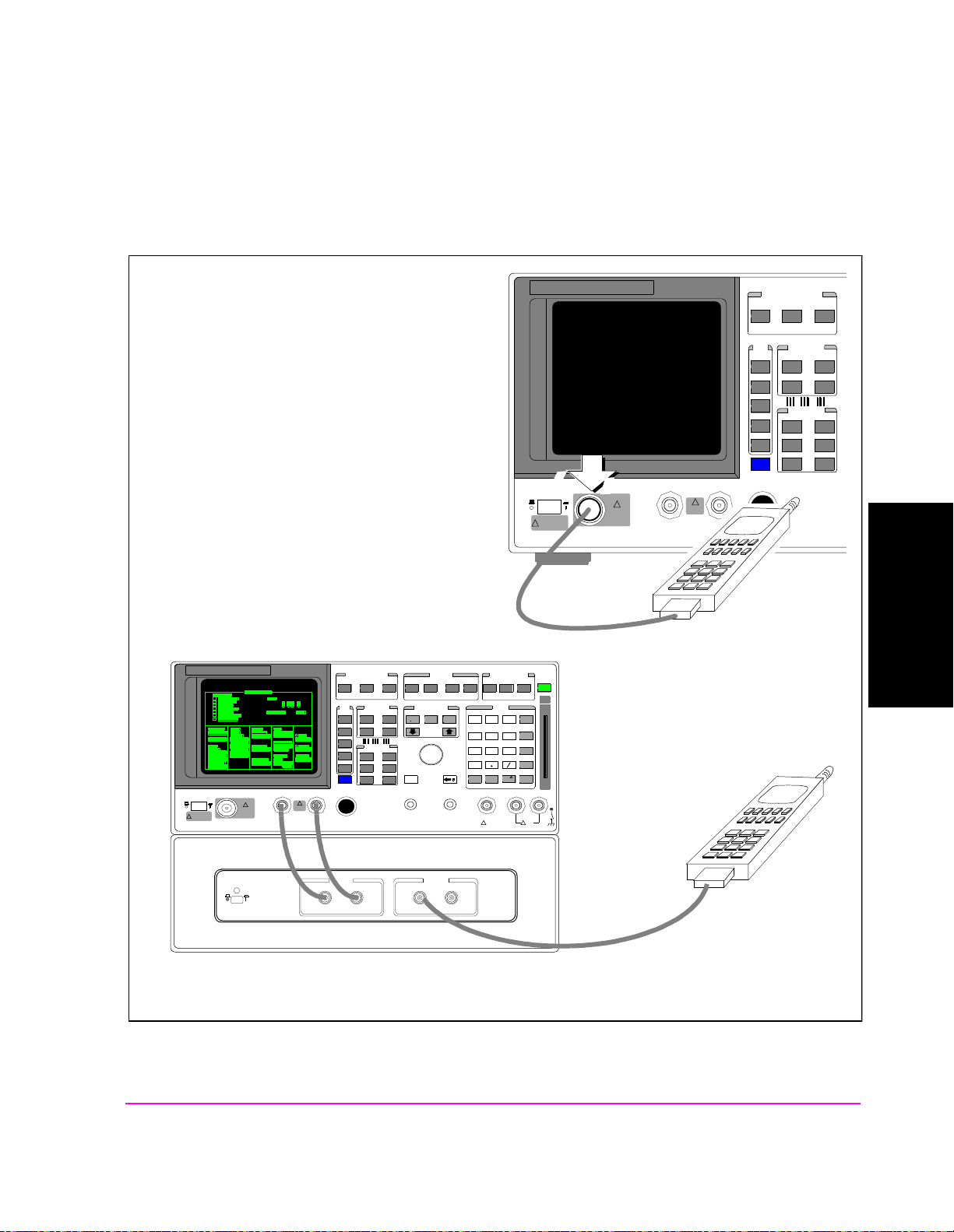
1. Connect the Test Set’s generator to the Test Set’s analyzer.
!
POWER
DO NOT APPLY
RF WHEN OFF
RF IN/OUT
MAX PWR
CDMA CALL CONTROL
CDMA SCRNS
CELL
CALL
CTRL
SPECTRUM
GEN
CTRL
ANALOG SCRNS
ENCODER
RF
ANL
AF
ANL
SPEC ANL
RF
GEN
END
CALL
RANGE
RX
TEST
MSRPT
TX
TEST
DECODER
RX
TEST
ACP
TX
TEST
SCOPE
DUPLEX
CALL ANS
USER DATA
k1’
k1
k2’
k2
k3’
k3
ASSIGN
k4
RELEASE
k5
DUPLEX OUT
MAX PWR
200 mW
!
ANTENNA IN
!
6 W
FUNCTIONS
MSG
PRINTER
HELP
PRINT
DATA FUNCTIONS
REF SET
METER
INCR
INCR
: 10
SET
LO LIMIT HI LIMIT
CURSOR
CONTROL
CANCELSHIFT
I/O CONFIG CONFIG
PREV TESTS
AVG
INCR X10
PUSH TO
SELECT
INSTRUMENT STATE
ADRS
SAVE
LOCAL
RECALL
789
456
123
+
0
ON/OFF
YES
Ω
NO
%
ppm
dBµV
W
AUDIO OUTSQUELCHVOLUMEMIC/ACC
MAX
!
12 v Pk
_
HOLD
MEAS
RESET
ENTER
dB
GHz
dBm
%
MHz
V
s
kHz
mV
ms
Hz
µV
AUDIO IN
!
Calibrating The Test Set
Chapter 1
PRESET
MEMOR
Y CARD
LOHI
MAX
42 v Pk
OR...
With
HP 83236 PCS INTERFACE
23
CDMA CALL
CALL ANS
USE DA
CDMA
k1’
CELL
CALL
k1
k2’
SPECTR
GEN
k2
k3’
k3
ANALOG
ASSIG
ENCO
RF
k4
RELE
k5
SPEC
RF
POWE
DO NOT
!
H
RF IN/
!
MAX PWR
POWER
ONOFF
83236B
PCS INTERFACE
!
MAX
ANTENNDUPLEX
FROM DUPLEX OUT TO ANT IN
TEST SET
MSG
END
HELP
RANG
REF
INCR
RX
LO HI
MSRP
TX
CURSO PUSH
DECO
RX
ACP
TXAF
SCOP
DUPL
CANCSHIFT
RF IN/OUT RF OUT only
FUNCTIO
PRINT
PRINT
DATA
METE
INCR
1.8-2.0 GHz UUT
I/O CONFI
PREV TESTS
AVG
INCR
INSTRUMENT
ADRS
SAVE
LOCA
RECA
789
456
123
+
0
Ω
YES
NO
ppm
ON/
AUDIO SQUELVOLUMIC/
MAX
!
HOLD
MEAS
PRESE
MEM
ENTE
dB
GHz
%
MHz
s
kHz
_
Hzms%
AUDIO
MAX
!
LHI

Chapter 1, Calibrate the Test Set
Channel Power Measurement Calibration
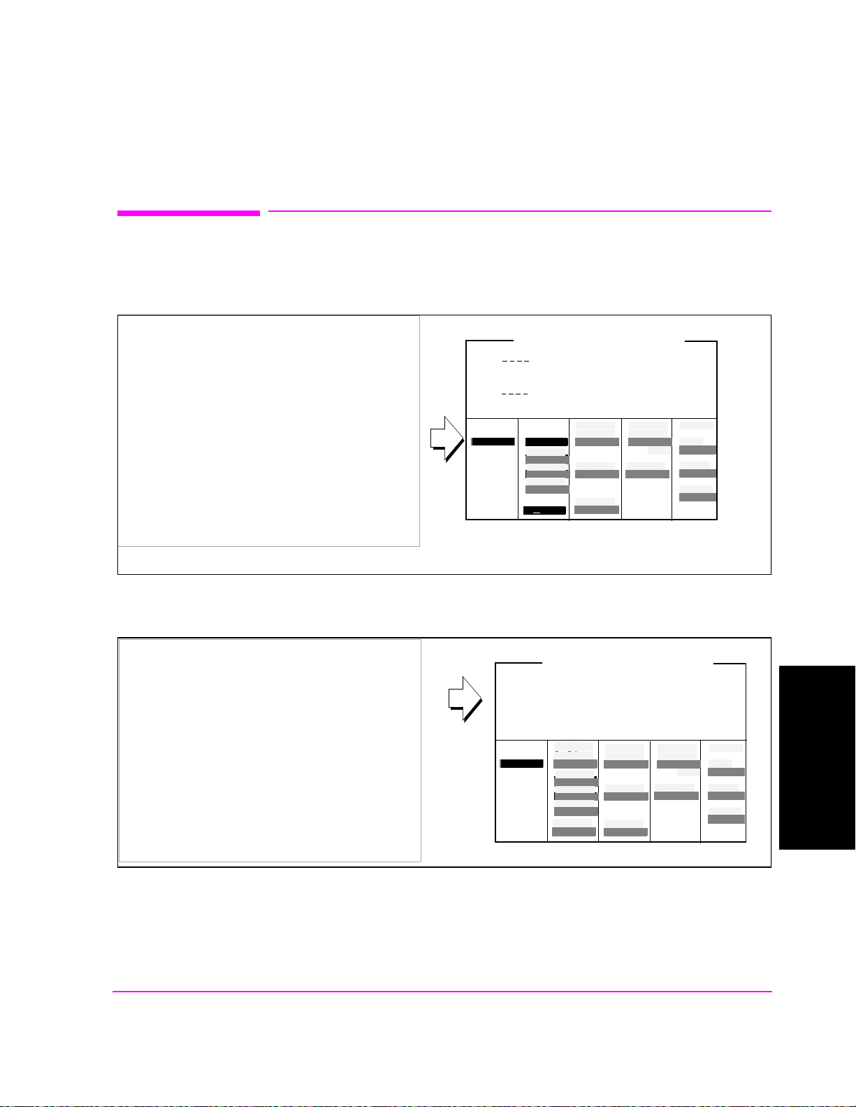
2. (Optional) Enter an alternate channel standard.
1. Press and release the SHIFT key and then press
CONFIGURE
the TESTS key to display the CONFIGURE
screen.
RF In/Out
- X.X
2. Select the Alt Chn Std field, and select a channel
standard from the list of choices.
3. Press the PREV key to return to the CDMA
CALL CONTROL screen.
Alt Chn Std
US PCS
Duplex Out
- X.X
Antenna In
- X.X
dB
Adding an alternate channel standard will increase the time required for the Test Set to perform Channel
Power Calibration, but should be performed if you will have an immediate need to test more than one type of
mobile station using more than one type of RF channel standard.
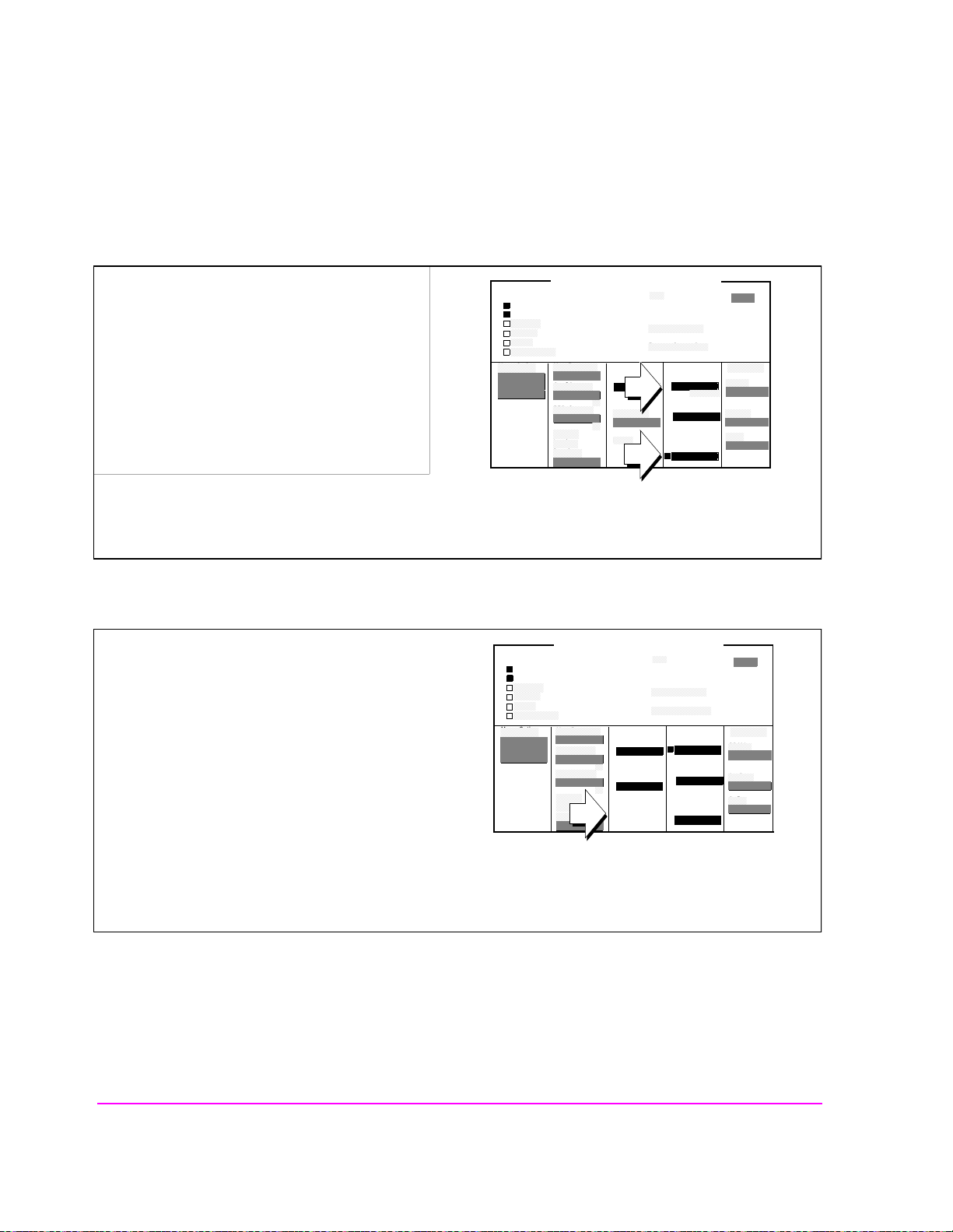
3. Select the Channel Power measurement.
1. If Chan Power is not displayed in the field as
shown, set this field to Chan Power.
Call Status
Transmitting
Page Sent
Access Probe
Connected
Softer Handoff
Hard Handoff
RF Channel
384
Register
Answer Mode
Auto/Manual
Call Limit
None/Page
CDMA CALL CONTROL
MS FER
Report
Interval
5 frames
Traffic
Data Mode
Svc Opt 1
Data Type
Echo
Avg Power
Power Zero
Chan Power
MS Database
ESN
-73.0
----
dBm/BW
To Screen
CDMA
CALL CNTL
Analog
RX TEST
Cnfig
PRNT CNFG
dBm
24

4. Calibrate the Channel Power measurement.
Chapter 1, Calibrate the Test Set
Channel Power Measurement Calibration
1.Select Calibrate to start the calibration.
Call Status
Transmitting
Page Sent
Access Probe
Connected
Softer Handoff
Hard Handoff
RF Channel
384
Register
Answer Mode
Auto/Manual
Call Limit
None/Page
CDMA CALL CONTROL
MS FER
Report
Interval
5 frames
Traffic
Data Mode
Svc Opt 1
Data Type
Echo
Power Meas
Calibrate
Chan Power
MS Database
ESN
-73.0
----
dBm/BW
Calibration may take a minute or longer, depending o n the RF Channel Std and Alt Chn St d field settings.
Average Power measurements are zeroed as part of the Channel Power calibration process.
Procedure Overview
Calibrating Channel Power measurements ensures that the Test Set achieves
accurate low-level CDMA power measurements.
Channel Power measurements:
• indicate power in a 1.23 MHz bandwidth
• are performed at one of the Test Set’s IF frequencies by a DSP (Digital Signal
Processor)
• use the Test Set’s average power detector to calibrate the relative levels measured at IF.
dBm
To Screen
CDMA
CALL CNTL
Analog
RX TEST
Cnfig
PRNT CNFG
Calibrating The Test Set
Chapter 1
Average Power measurements are zeroe d as part of the Chann el Power cal ibrati on
process.
25

Chapter 1, Calibrate the Test Set
RF Generator Level Calibration (PCS Interface)
RF Generator Level Calibrat ion (PCS Interfa ce)
This procedure is performed only on Test Sets configured with an HP 83236B
PCS Interface.
Approximate time: 15 seconds
1. Start calibration procedure.
1. Press and release the SHIFT key and then press
the TESTS key to display the CONFIGURE
screen.
CONFIGURE
2. Select the Calibrate to start the calibration.
RF Gen Lvl
Calibrate
The message "Calibrating RF Generator Levels" will be displayed until the calibration process has
completed.
Procedure Overview
During this proced ure, the PCS Interfa ce’ s internal compensatio n f ac tor s ar e used
to compute attenuator path values for the PCS Interface generator and the required
signal level from the Test Set’s DUPLEX OUT port.
NOTE: This procedure will cause a currently connected call to drop . (The RF IN/OUT path is
momentarily de-coupled from the front panel connector during this calibration.)
26

Chapter 1, Calibrate the Test Set
Average Power Measurement Zeroing
Average Power Measurement Zeroing
Approximate length of time: 2 seconds
1. Remove power from the RF IN/OUT connector.
!
POWER
DO NOT APPLY
RF WHEN OFF
RF IN/OUT
MAX PWR
!
6 W
MAX PWR
!
200 mW
ANTENNA INDUPLEX OUT
CDMA CALL CONTRO L
CDMA SCRNS
CELL
CALL
CTRL
SPECTRUM
GEN
CTRL
ANALOG SCRNS
ENCODER
RF
ANL
AF
ANL
SPEC ANL
RF
GEN
END
CALL
RANGE
RX
TEST
MSRPT
TX
TEST
DECODER
RX
TEST
ACP
TX
TEST
SCOPE
DUPLEX
CALL ANS
USER DATA
k1’
k1
k2’
k2
k3’
k3
ASSIGN
k4
RELEASE
k5
FUNCTIONS
MSG
PRINTER
HELP
PRINT
DATA FUNCTIONS
REF SET
METER
INCR
INCR
: 10
SET
LO LIMIT HI LIMIT
CURSOR
CONTROL
CANCELSHIFT
I/O CONFIG CONFIG
PREV TESTS
AVG
INCR X10
PUSH TO
SELECT
INSTRUMENT STATE
ADRS
LOCAL
789
456
123
0
YES
NO
ppm
ON/OFF
W
AUDIO OUTSQUELCHVOLUMEMIC/AC C
MAX
!
12 v Pk
SAVE
RECALL
+
Ω
%
dBµV
_
HOLD
MEAS
RESET
ENTER
dB
GHz
dBm
%
MHz
V
s
kHz
mV
ms
Hz
µV
AUDIO IN
!
Calibrating The Test Set
Chapter 1
PRESET
MEMOR
Y CARD
LOHI
MAX
42 v Pk
OR...
With
HP 83236 PCS INTERFACE
27
CDMA CALL
CALL ANS
USE DA
CDMA
k1’
RANG
CELL
CALL
k1
k2’
SPECTR
MSRP
GEN
k2
k3’
k3
ANALOG
ASSIG
DECO
ENCO
RF
k4
RELE
k5
SCOP
SPEC
RF
DUPL
POWE
DO NOT
!
RF IN/
H
!
MAX PWR
POWER
ONOFF
DUPLEX
83236B
PCS INTERFACE
!
MAX
ANTENN
FROM DUPLEX OUT TO ANT IN
TEST SET
MSG
END
HELP
REF
INCR
RX
LO HI
TX
CURSO PUSH
RX
ACP
TXAF
CANCSHIFT
RF IN/OUT RF OUT only
FUNCTIO
PRINT
PRINT
DATA
METE
INCR
1.8-2.0 GHz UUT
I/O CONFI
PREV TESTS
AVG
INCR
INSTRUMENT
ADRS
SAVE
LOCA
RECA
789
456
123
+
0
Ω
YES
NO
ppm
ON/
AUDIO SQUELVOLUMIC/
MAX
!
HOLD
MEAS
PRESE
MEM
ENTE
dB
GHz
%
MHz
s
kHz
_
Hzms%
AUDIO
MAX
!
LHI

Chapter 1, Calibrate the Test Set
Average Power Measurement Zeroing
2. Check the Test Set’s output power.
Manual Operation:
1. Press the GEN CTRL key to display the
CDMA
2. If the RF Power field is displaying a value less
than or equal to −75 dBm/BW, the Test Set’s
output power is low enough for zeroing average
power measurements. Continue with the next
step.
If the RF Power field is displaying a value greater
than −75 dBm/BW:
GENERATOR CONTROL screen.
Sector Pwr
-75.0
dBm/BW
CDMA GENERATOR CONTROL
AWGN
Off
RF Power
−
75.00
dBm/BW
Eb/Nt
−−−−
Press the PRESET key. Or if you have other
settings you do not want chan ged, turn off
output power as follows:
Use the ON/OFF key along with the knob to
turn off Sector A Power and AWGN.
Lowering power from the CDMA generators will prevent output power from internally cross-coupling to the
RF IN/OUT path during Average Power measurement zeroing.
Presetting the Test Set will turn off AWGN and will set Sector A Power to a level that is low enough to prevent
cross-coupling between gener at o r and input signal paths.
28

3. Select the Average Power measurement.
Chapter 1, Calibrate the Test Set
Average Power Measurement Zeroing
1. Press the CDMA SCRNS - TX TEST key to
display the CDMA CELLULAR MOBILE
TRANSMITTER TEST screen.
2. If Avg Power is not displayed in the field as
shown, select Avg Power.
CDMA CELLULAR MOBILE TRANSMITTER TEST
Avg Power
Calibrating The Test Set
Chapter 1
29

Chapter 1, Calibrate the Test Set
Average Power Measurement Zeroing
4. Zero the Average Power measurement.
1. Select Zero to zero the Average Power
measurement.
CDMA CELLULAR MOBILE TRANSMITTER TEST
Avg Power
Power Meas
Zero
During this process, the message "Zeroing Average Power" will be displayed (for about 2 seconds).
If RF power was not lowered as shown in step 2, the Test Set will display "Zero degraded. Reduce generator
level for best results."
Procedure Overview
This procedure establishes a 0 dBm reference for Average Power measurements.
Average Power measurement mode is used on higher-level signals. Lower-level
power measurements are performed by the Test Set’s Channel Power
measurement.
NOTE: A misleading Average Power measurement may appear when low (or no) signal power is
applied to the RF Input! When the RF generator’s output port selection is RF IN/OUT
some of the signal energy from the Test Set’s generator is detected by the Test Set’s
broadband average power meter. This condition does not affect typical CDMA
measurements for two reasons: 1) During Average Power measurements, CDMA generator
levels are too low to introduce significant energy to the power detector. 2) When the
generator level is high enough to introduce significant energ y to the power detector, the
mobile station’s signal power should be within the range of Channel Power measurements.
Channel power measurements are frequency-selective, an d do not detect significant energy
from the Test Set’s generator, which is tuned 45 MHz away from the analyzer.
30
,
Chapter 1, Calibrate the Test Set
Correcting for RF Path Loss
Correcting for RF Path Loss
1. Enter the (cable) path loss from the Test Set to the mobile station.
If you do not know the path loss, see "Determining RF Path Loss" on page 33
1. Press and release the SHIFT key and then press
the TESTS key to display the CONFIGURE
screen.
2.Select the RF In/Out field and enter a value for
RF path loss.
Example: If the cable loss is 2 dB, enter −2 in the
RF In/Out field.
When the RF Level Offset is turned on in the next step, the displayed Average or Channel Pow er measurement
will be increased by 2 d B and the displayed
Sector A, AWGN, and RF Power outputs will be decreased by
2 dB. No actual level changes occur as a result of turning on RF Level Offset.
CONFIGURE
RF In/Out
- X.X
Duplex Out
- X.X
Antenna In
- X.X
dB
Calibrating The Test Set
Chapter 1
2. Turn on the RF Level Offset.
1. Set the RF Level Offset field to On
31
CONFIGURE
RF Level
Offset
On/Off
RF In/Out
- X.X
Duplex Out
- X.X
Antenna In
- X.X
dB

Chapter 1, Calibrate the Test Set
Correcting for RF Path Loss
Procedure Overview
Using the RF Level Offset feature of the Test Set corrects for RF path power
losses that occur in cabling and connectors between the Test Set and a mobile
station.
It is highly recommended that RF path loss is corrected for. Besides returning
power measurements that do not have to be adjusted to account for RF path loss,
the Test Set uses t he val u es you enter in this procedur e to adjust the ana lyz er path
attenuation to an optimum value for demodulation and measurement functions.
NOTE: The settings you made in this procedure must be re-entered after a power-cycle or
instrument preset.
32

Chapter 1, Calibrate the Test Set
Determining RF Path Loss
Determining RF Pa th Loss
The following procedure descr ibes how to use the Test Set to determin e path loss.
Procedure Prerequisites
Provide hardware for making a reference measurement.
You must provide a reference cable and the cable adapters necessary to connect
the reference cable along with the hardware used to connect the Test Set to the
mobile station. Choose a reference cable that has as low of signal loss as possible.
Calibrating The Test Set
Chapter 1
33

Chapter 1, Calibrate the Test Set
Determining RF Path Loss
1. Connect a reference cable(s).
!
POWER
DO NOT APPLY
RF WHEN OFF
RF IN/OUT
MAX PWR
!
6 W
OR...
With
HP 83236 PCS INTERFACE
MAX PWR
200 mW
CDMA CALL CONTROL
CDMA SCRNS
CELL
CALL
CTRL
SPECTRUM
GEN
CTRL
ANALOG SCRNS
ENCODER
RF
ANL
AF
ANL
SPEC ANL
RF
GEN
END
CALL
RANGE
RX
TEST
MSRPT
TX
TEST
DECODER
RX
TEST
ACP
TX
TEST
SCOPE
DUPLEX
CALL ANS
USER DATA
k1’
k1
k2’
k2
k3’
k3
ASSIGN
k4
RELEASE
k5
FUNCTIONS
MSG
PRINTER
HELP
PRINT
DATA FUNCTIONS
REF SET
METER
INCR
INCR
: 10
SET
LO LIMIT HI LIMIT
CURSOR
CONTROL
CANCELSHIFT
I/O CONFIG CONFIG
PREV TESTS
AVG
INCR X10
PUSH TO
SELECT
!
ANTENNA INDUPLEX OUT
INSTRUMENT STATE
ADRS
SAVE
LOCAL
RECALL
789
456
123
+
0
YES
ON/OFF
Ω
NO
%
ppm
dBµV
W
AUDIO OUTSQUELCHVOLUMEMIC/ACC
MAX
!
12 v Pk
_
HOLD
MEAS
RESET
ENTER
dB
GHz
dBm
%
MHz
V
s
kHz
mV
ms
Hz
µV
AUDIO IN
!
42 v Pk
PRESET
MEMOR
Y CARD
LOHI
MAX
Low-loss reference cable
CDMA CALL
CALL ANS
USE DA
CDMA
k1’
CELL
CALL
k1
k2’
SPECTR
GEN
k2
k3’
k3
ANALOG
ASSIG
ENCO
RF
k4
RELE
k5
SPEC
RF
POWE
DO NOT
!
RF IN/
MAX PWR
!
!
MAX
ANTENNDUPLEX
MSG
END
HELP
RANG
REF
INCR
RX
LO HI
MSRP
TX
CURSO PUSH
DECO
RX
ACP
TXAF
SCOP
DUPL
CANCSHIFT
FUNCTIO
PRINT
PRINT
DATA
METE
INCR
I/O CONFI
PREV TESTS
AVG
INCR
INSTRUMENT
ADRS
SAVE
LOCA
RECA
789
456
123
+
0
Ω
YES
NO
ppm
ON/
AUDIO SQUELVOLUMIC/
MAX
!
HOLD
MEAS
PRESE
MEM
ENTE
dB
GHz
%
MHz
s
kHz
_
Hzms%
AUDIO
MAX
!
LHI
83236B
H
PCS INTERFACE
POWER
ONOFF
TEST SET
FROM DUPLEX OUT TO ANT IN
RF IN/OUT RF OUT only
Low-loss reference cable
34
1.8-2.0 GHz UUT

2. Configure the Test Set for RF loopback.
1. Press and release the SHIFT key and then press
the TESTS key to display the CONFIGURE
screen.
2. Set the Output Port field to Dupl
Interface) or only
(with PCS Interface).
Skip step 3 (bel ow) if a PCS Interface is
configured.
(without PCS
Test Set
without
PCS
Interface
Chapter 1, Calibrate the Test Set
Determining RF Path Loss
CONFIGURE
Output Port
RF Out/Dupl
Input Port
RF In/Ant
Calibrating The Test Set
Chapter 1
3. Set the Input Port field to RF In
.
CONFIGURE
Test Set
with
PCS
Interface
Output Port
RF Out/0nly
35
Chapter 1, Calibrate the Test Set
Determining RF Path Loss
3. Set a 0 dBM reference for the path loss measurement.
1. Press the CDMA SCRNS - TX TEST key to
display the CDMA CELLULAR MOBILE
TRANSMITTER TEST screen.
CDMA CELLULAR MOBILE TRANSMITTER TEST
2. Select the Sector Power field and set the value
to −11.0 dBm/BW with the DATA keys.
3. Select the units-of-measure field and press the
knob.
4. Press and release the SHIFT key, then press the
INCR ÷
10 (REF SET) key.
5. Press the knob to set start measurements using
the 0 dBm reference.
Avg Power dBm
0.00
Reference
Sector A
Power
-11.0
dB/BW
36

4. Connect the cable and hardware being measured for path loss.
Chapter 1, Calibrate the Test Set
Determining RF Path Loss
POWER
DO NOT APPLY
!
RF WHEN OFF
RF IN/OUT
Cable being measured
OR...
MAX PWR
CDMA CALL CONTROL
CDMA SCRNS
CELL
CALL
CTRL
SPECTRUM
GEN
CTRL
ANALOG SCRNS
ENCODER
RF
ANL
AF
ANL
SPEC ANL
RF
GEN
END
CALL
RANGE
RX
TEST
MSRPT
TX
TEST
DECODER
RX
TEST
ACP
TX
TEST
SCOPE
DUPLEX
CALL ANS
USER DATA
k1’
k1
k2’
k2
k3’
k3
ASSIGN
k4
RELEASE
k5
DUPLEX OUT
MAX PWR
200 mW
!
ANTENNA IN
!
6 W
FUNCTIONS
MSG
PRINTER
HELP
PRINT
DATA FUNCTIONS
REF SET
METER
INCR
INCR
: 10
SET
LO LIMIT HI LIMIT
CURSOR
CONTROL
CANCELSHIFT
I/O CONFIG CONFIG
PREV TESTS
AVG
INCR X10
PUSH TO
SELECT
INSTRUMENT STATE
ADRS
SAVE
LOCAL
RECALL
789
456
123
+
0
ON/OFF
YES
Ω
NO
%
ppm
dBµV
W
AUDIO OUTSQUELCHVOLUMEMIC/ACC
MAX
!
12 v Pk
_
HOLD
MEAS
RESET
ENTER
dB
GHz
dBm
%
MHz
V
s
kHz
mV
ms
Hz
µV
AUDIO IN
!
PRESET
MEMOR
Y CARD
LOHI
MAX
42 v Pk
Calibrating The Test Set
Chapter 1
Low-loss reference cable
CDMA CALL
CALL ANS
USE DA
CDMA
k1’
CELL
CALL
k1
k2’
SPECTR
GEN
k2
k3’
k3
ANALOG
ASSIG
ENCO
RF
k4
RELE
k5
SPEC
RF
POWE
DO NOT
!
RF IN/
MAX PWR
!
!
MAX
ANTENNDUPLEX
MSG
END
HELP
REF
RANG
INCR
RX
LO HI
MSRP
TX
CURSO PUSH
DECO
RX
ACP
TXAF
SCOP
CANCSHIFT
DUPL
FUNCTIO
PRINT
PRINT
DATA
METE
INCR
I/O CONFI
PREV TESTS
AVG
INCR
INSTRUMEN T
ADRS
SAVE
LOCA
RECA
789
456
123
+
0
Ω
NO
YES
ppm
ON/
AUDIO SQUELVOLUMIC/
MAX
!
HOLD
MEAS
PRESE
MEM
ENTE
dB
GHz
%
MHz
s
kHz
_
Hzms%
AUDIO
MAX
!
LHI
With
HP 83236 PCS INTERFACE
37
83236B
H
PCS INTERFACE
POWER
ONOFF
TEST SET
FROM DUPLEX OUT TO ANT IN
1.8-2.0 GHz UUT
RF IN/OUT RF OUT only
Chapter 1, Calibrate the Test Set
Determining RF Path Loss
5. Determine the path loss.
Observe the average power measurement reading.
This is the measured RF path loss that should be
entered in the Test Set’s Configure screen.
See "Correcting for RF Path Loss" on page 31.
6. Re-configure the Test Set.
Manual Operation:
1. Press the PRESET key
CDMA CELLULAR MOBILE TRANSMITTER TEST
Avg Power dBm
-3.00
Ref
Sector A
Power
CDMA CALL CONTRO L
CDMA SCRNS
CELL
CALL
CTRL
SPECTRUM
GEN
CTRL
ANALOG SCRNS
ENCODER
RF
ANL
AF
ANL
SPEC ANL
RF
GEN
END
CALL
RANGE
RX
TEST
MSRPT
TX
TEST
DECODER
RX
TEST
ACP
TX
TEST
SCOPE
DUPLEX
CALL ANS
USER DATA
k1’
k1
k2’
k2
k3’
k3
ASSIGN
k4
RELEASE
k5
FUNCTIONS
MSG
PRINTER
HELP
PRINT
DATA FUNCTIONS
REF SET
METER
INCR
INCR
: 10
SET
LO LIMIT HI LIMIT
CURSOR
CONTROL
CANCELSHIFT
I/O CONFIG CONFIG
PREV TESTS
AVG
INCR X10
PUSH TO
SELECT
INSTRUMENT STATE
ADRS
LOCAL
789
456
123
0
YES
NO
ppm
ON/OFF
W
AUDIO OUTSQUELCHVOLUMEMIC/AC C
-11.0
SAVE
RECALL
+
Ω
%
dBµV
dB/BW
_
HOLD
MEAS
RESET
ENTER
dB
GHz
dBm
%
MHz
V
s
kHz
mV
ms
Hz
µV
AUDIO IN
PRESET
MEMOR
Y CARD
LOHI
38
MAX
!
12 v Pk
MAX
!
42 v Pk

Procedure Overview
Chapter 1, Calibrate the Test Set
Determining RF Path Loss
The path loss between the Test Set and the Mobile station is measured by first
establishing a reference path loss, then including the hardware (cabling, adapters,
and that will connect the Test Set to a mobile station during testing.
The path loss value obtained in this procedure is used in
Loss" on page 31
.
"Correcting for RF Path
Calibrating The Test Set
Chapter 1
39

Chapter 1, Calibrate the Test Set
Determining RF Path Loss
40

2
Set Up a Call
Setting Up A Call
Chapter 2
41

Chapter 2, Set Up a Call
Setting Up a CDMA Call
Setting Up a CDMA Call
When you test a CDMA or dual-mode (CDMA and analog) mobile station you
should first attempt to set up a CDMA call. Once a CDMA call is connected,
mobile station transmitter power measurements are displayed and many other
CDMA measurements are available when by selecting the Test Set’s CDMA
screens.
If the mobile station has dual-mode capability, the CDMA call can be handed off
to analog operation at the press of a knob. With the mobile station operating in
analog mode, fundamental audio and RF transceiver measurements are provided
on one screen.
NOTE: If the mobile station being tested is not able to make a call, analog transceiver
measurements can be made using the Test Set’s general-purpose measurement capability.
Refer to the ANALOG MEAS, SPECTRUM ANALYZER (Opt 012 only), and
OSCILLOSCOPE screen descriptions in the HP 8924E User’s Guide
Requirements:
Before you start this procedure, make sure you have the following items or
information , or meet the following cond itions.
❒ Isolation or shielding apparatus for the mobile station if significant signal interference is
present.
❒ Hardware (cables, adapters, and so forth) to ma ke the RF connection from the Test Set’s
front-panel type N connector to the mobile station (cabling should be as low-loss as
possible).
❒ Knowledge of the CDMA RF channel that mobile station is programmed to find service
on.
❒ Knowledge of the CDMA protocol and RF channel standard used by mobile station.
❒ A power supply with dc-power cabling to the mobile station or a battery that has
sufficient charge to power the mobile station for the duration of testing.
❒ (Optional) If you want to make analog audio measurements, a way to make audio
connections (microphone and ear) from the mobile station to the Test Set’s audio BNC
front-panel connectors.
NOTE: Mobile stations operating in the PCS frequency band (1900 MHz) can be tested only on
HP 8924E Test Set’s that are configured with the HP 83236 PCS Interface. This interface
attaches to the bottom of the HP 8924E inside of a “shell” called the Ben c h Top Kit.
42

Setting up a Call
1. Preset the Test Set.
Chapter 2, Set Up a Call
Setting up a Call
1. If the Test Set is not powered on:
a. turn on power to the PCS Interface (if one is
present), then...
b.turn on power to the Test Set. Wait for the Test
Set to complete its power-up routine
2. Press the PRESET key (to begin this procedure
in a known state).
Call Status
Transmitting
Page Sent
Access Probe
Connected
Softer Handoff
Hard Handoff
RF Channel
384
Register
Softer
Handoff
Begin/End
Answer Mode
Auto/Manual
Call Limit
None/Page
CDMA CALL CONTROL
MS FER
Report
Interval
5 frames
by # frames
On/Off
by # frames
On/Off
5
Traffic
Data Mode
Svc Opt 1
Data Type
Echo
Echo Delay
Short
Avg Power
Power Zero
MS FER Report
Avg Power
MS ID
Phone Num
5099214001
MS Database
ESN
1234
Sector A
Power
-73.0
----
dBm/BW
%
dBm
To Screen
CDMA
CALL CNTL
Analog
RX TEST
Cnfig
PRNT CNFG
Pressing the PRESET key will configure the Test Set using factory default settings, and display the CDMA
CALL CONTROL screen.
If you have the Test Set configured to operate with a PCS Interface, and you do not turn PCS Interface
power on before the Test Set, the message “PCS Interface not found. Check power, cabling or CONFIG.”
will be displayed. To correct this condition, follow the correct sequence of powering up these two units.
Setting Up A Call
Chapter 2
43

Chapter 2, Set Up a Call
Setting up a Call
2. Enter the CDMA Protocol and RF Channel Standard.
1. Press the CDMA SCRNS - CALL CTRL key to
display the CDMA CALL CONTROL screen.
2. Select the Protocol field.
3. Select a protocol from the list of choices.
5. Select the RF Chan Std field.
6. Select one of the standards from the list of
choices.
Call Status
Transmitting
Page Sent
Access Probe
Connected
Softer Handoff
Hard Handoff
RF Channel
384
Register
Softer
Handoff
Begin/End
Protocol
Auto/Manual
RF Chan Std
None/Page
CDMA CALL CONTROL
MS FER
Report
Interval
5 frames
by # frames
On/Off
by # frames
On/Off
5
Traffic
Data Mode
Svc Opt 1
Data Type
Echo
Echo Delay
Short
Avg Power
Power Zer o
MS FER Report
Avg Power
MS ID
Phone Num
5099214001
MS Database
ESN
1234
Sector A
Power
-75.0
----
dBm/BW
The list of RF Chan Std choices includes only those supported by the hardware configuration. Some RF
channel standards require the HP 83236B with Option 007 (Wideband). Refer to the RF Chan Std field
description in the HP 8924C User’s Guide.
%
dBm
To Screen
CDMA
CALL CNTL
Analog
RX TEST
Cnfig
PRNT CNFG
44
3. Enter the Mobile Station’s CDMA RF Channel number.
Chapter 2, Set Up a Call
Setting up a Call
1. Select the RF Channel field.
2. Enter the CDMA RF channel number that your
mobile station is assigned to. Tip: Use the
DATA keys.
3. Press the ENTER key or the knob to enter the
value.
Call Status
Transmitting
Page Sent
Access Probe
Connected
Softer Handoff
Hard Handoff
RF Channel
384
Register
Softer
Handoff
Begin/End
Protocol
IS-95A
RF Chan Std
MS AMPS
CDMA CALL CONTROL
MS FER
Report
Interval
5 frames
by # frames
On/Off
by # frames
On/Off
5
Traffic
Data Mode
Svc Opt 1
Data Type
Echo
Echo Delay
Short
Avg Power
Power Zer o
MS FER Report
Avg Power
MS ID
Phone Num
5099214001
MS Database
ESN
1234
Sector A
Power
-75.0
----
dBm/BW
%
dBm
To Screen
CDMA
CALL CNTL
Analog
RX TEST
Cnfig
PRNT CNFG
The mobile station’s pri mary CDMA channel depen ds on i ts preferr ed se rving sys tem (System A or System
B) and Protocol. Listed below are the primary CDMA channel numbers specified in EIA/TIA IS-95.
System A Primary CDMA Channel: 283.
System B Primary CDMA Channel: 384.
Setting Up A Call
Chapter 2
45
Chapter 2, Set Up a Call
Setting up a Call
4. Enter the Mobile Station’s preferred system (SID).
1. Press then release the blue SHIFT key, then
CDMA CELL SITE CONFIGURATION
press the CDMA SCRNS - CALL CTRL key to
select the CDMA CELL SITE
CONFIGURATION screen.
System ID
384
2. Select the System ID field.
3. Enter the mobile station’s preferred system
identification.
4. Press the PREV key to return to the CDMA
CALL CONTROL screen.
System ID is programmed into the mobile station by the service providers. When power is turned on, the
mobile station searches for CDMA signals. When the CDMA signal is demodulated, the mobile station
finds out whether or no t the Test Set’s system matches the system it is programmed to prefer service on.
Depending on how the mobile station is programmed, entering an incorrect number in this field could
cause the mobile station to delay any call-p rocessi ng until it has exhau sted a search of other RF channels ,
or it may not allow any calls at all.
46
5. Make the RF connection between the Test Set and the mobile station.
Chapter 2, Set Up a Call
Setting up a Call
Make sure all connections to the mobile station,
including dc power, are made.
Some mobile station’s do not have an RF
connection. In these cases, the manufacturer will
usually make a fixture, such as a car adapter, that
will provide an RF cable connection. The mobile
station snaps into the fixture and an RF connection
is made through an electromagnetic coupler near
the mobile station’s antenna.
CDMA CALL
CALL ANS
USE DA
CDMA
k1’
CELL
CALL
k1
k2’
SPECTR
GEN
k2
k3’
k3
ANALOG
ASSIG
ENCO
RF
k4
RELE
k5
SPEC
RF
POWE
DO NOT
!
RF IN/
MAX PWR
!
!
MAX
ANTENNDUPLEX
MSG
END
HELP
RANG
REF
INCR
RX
LO HI
MSRP
TX
CURSO PUSH
DECO
RX
ACP
TXAF
SCOP
DUPL
CANCSHIFT
PRINT
PRINT
DATA
METE
INCR
FUNCTIO
PREV TESTS
AVG
INCR
I/O CONFI
INSTRUMENT
ADRS
SAVE
LOCA
RECA
789
456
123
_
+
0
Ω
YES
NO
ppm
ON/
AUDIO SQUELVOLUMIC/
MAX
!
POWER
DO NOT APPLY
!
RF WHEN OFF
HOLD
MEAS
PRESE
MEM
ENTE
dB
GHz
%
MHz
s
kHz
Hzms%
AUDIO
LHI
MAX
!
CDMA CALL CONTROL
CALL ANS
USER
CDMA SCRNS
k1’
CELL
CALL
k1
CTRL
k2’
SPECTRUM
GEN
k2
CTRL
k3’
k3
ANALOG SCRNS
ASSIGN
ENCODER
RF
k4
ANL
RELEASE
AF
k5
ANL
SPEC ANL
RF
SHIFT
GEN
MIC/ACC
RF IN/OUT
MAX PWR
!
6 W
DUPLEX OUT
MAX PWR
200 mW
!
ANTENNA IN
OR...
With
HP 83236 PCS INTERFACE
END
CALL
RANGE
TEST
MSRPT
TEST
DECODER
TEST
ACP
TEST
SCOPE
DUPLEX
RX
TX
RX
TX
Setting Up A Call
Chapter 2
83236B
H
PCS INTERFACE
POWER
ONOFF
TEST SET
FROM DUPLEX OUT TO ANT IN
1.8-2.0 GHz UUT
RF IN/OUT RF OUT only
47

Chapter 2, Set Up a Call
Setting up a Call
6. Turn on power to the mobile station.
Wait until the mobile station has found digital
(CDMA) service (this should take no longer
than about 30 seconds).
If the mobile station does not find digital
service, refer to the
Checklist" on page 52
Most mobile stations have a NO SERVICE annunciator that will go out when the mobile station has found
service. Other mobile stations use an LED that indicates when service has been found.
"Problem Solving
.
D
(igital)
If a strong signal from an analog base station is present, or the mobile station is programmed to prefer analog
service, the mobile station may not find digital service. If this condition exists, re-program the phone, or isolate
it from the competing analog signal using an RF isolation chamber.
Caution: Do not exceed 6 W continuous power into the Test Set’s RF IN/OUT connector with any transmitter.
48

7. Dial 1234 on the mobile station’s handset, then press SEND.
You can use practically any sequence of numbers to perform
this step. 1,2,3 was chosen simply for convenience.
The Test Set’s Access Probe annunciator will light, indicating
that the mobile station sent an access probe sequence, then
the Connected annunciator will light.
After a mobile station has successfully originated a call, you
will see the mobile station’s identification displayed in the
MS Database field.
Another way to retrieve MS Database data from the mobile
station is by selecting the Register fiel d b e fore a call is
connected.
Call Status
Transmitting
Registering
Page Sent
Access Probe
Connected
Softer Handoff
RF Channel
384
Register
Softer
Handoff
Begin/End
Protocol
IS-95A
RF Chan Std
Register
MS AMPS
MS FER
Report
Interval
5 frames
by # frames
On/Off
by # frames
On/Off
5
Chapter 2, Set Up a Call
CDMA CALL CONTROL
Traffic
Data Mode
Svc Opt 1
Data Type
Echo
Echo Delay
2 Seconds
Avg Power
Power Zer o
Setting up a Call
MS FER Report
Avg Power
----
MS ID
Phone Num
5099214001
MS Database
Register
Sector A
Power
-75.0
dBm/BW
CDMA
CALL CNTL
Analog
RX TEST
Cnfig
PRNT CNFG
%
dBm
To Screen
Setting Up A Call
Chapter 2
.
Note: When the MS Database field d isplays
the current mobile station’s identification, a
call can be originated from the Test Set by
pressing the CALL key.
49
CDMA CALL
CALL ANS
USE DA
CDMA
k1’
CELL
CALL
k1
k2’
SPECTR
GEN
k2
k3’
k3
ANALOG
ASSIG
ENCO
RF
k4
RELE
k5
SPEC
RF
POWE
DO NOT
!
MAX PWR
!
!
MAX
MSG
END
HELP
REF
RANG
INCR
RX
LO HI
MSRP
TX
CURSO PUSH
DECO
RX
ACP
TXAF
SCOP
CANCSHIFT
DUPL
PRINT
PRINT
DATA
METE
INCR
FUNCTIO
I/O CONFI
PREV TESTS
AVG
INCR
INSTRUMENT
ADRS
SAVE
LOCA
RECA
789
456
123
_
+
0
Ω
NO
YES
ppm
ON/
AUDIO SQUELVOLUMIC/
MAX
!
HOLD
MEAS
PRESE
MEM
ENTE
dB
GHz
%
MHz
s
kHz
Hzms%
AUDIO
LHI
MAX
!

Chapter 2, Set Up a Call
Setting up a Call
8. Speak into the mobile station’s microphone.
Your voice will be echoed back wi th a 2 second
delay.
H e l l o
H e l l o
This test is referred to as “Voice Echo” and is performed with the mobile station connected on a Service
Option 1 or Service Option 32768 call.
Voice Echo is a subjective test of the mobile station’s ability to encode your voice, modulate the carrier with the
information data representin g your voice, and demodulate/decode the same voice information, then outp utting
an audio reproduction of you voice on the earpiece of the mobile station.
50

Procedure Overview
Many mobile station tests performed by the Test Set require that a call be
connected. To set up a call, the Test Set must be configured to include:
❒ The mobile station’s CDMA RF Channel
❒ The mobile station’s Protocol
❒ The mobile station’s RF Channel Standard
❒ The mobile station’s system identification (unless mobile station roams).
The steps beginning on page 42 describe how to make a mobile st at ion originated
call (by dialing number s on the mobil e station). The mobile stat ion regis ters as the
call is being connected, but there are other circumstances that can cause mobile
station registration. They are:
Chapter 2, Set Up a Call
Procedure Overview
• Power-up registration (usually initiated when mobile station is turned on)
and
• Zone-based registration (initiated by selecting the field labeled Register)
Regardless of which event causes the mobile station to register, the field labeled
MS Database displays the mobile stati on’s identif ication. As soon as you see this
field updated, you have the option of making a base station originated call by
pressing the CALL key on the Test Set’s front panel.
Setting Up A Call
Chapter 2
51

Chapter 2, Set Up a Call
Problem Solving Checklist
Problem Solving Checklist
If the mobile station does not find service, does not register, or does not connect
when a number is dialed on it, check the following items:
❒ Is the RF cable connected?
❒ Is the RF Channel number correct? (Set the RF Channel on the CDMA Call Control
screen.)
❒ Is Sector A Power adequate? If interference f rom other cellul ar band signal s is present,
Sector A Power may need to be set to a level greater than the instrument’s preset value
of −75 dBm/BW. (Set Sector A Power on the CDMA Call Co ntrol screen.) Example: If
the mobile station is finding analog service, adjust Sector A Power to −30 dBm/BW,
then cycle power on the mobile station. Isolating the mobile station may be necessary.
❒ Is the AWGN generator (CDMA Gen Control screen) off?
❒ Is the mobile station programmed to roam? If not, set the System ID on the CDMA Cell
Site Configuration screen, then cycle power on the phone.
❒ Are the entries in the Rgstr SID and Rgstr NID fields valid entries for the mobile
station? (The Rgstr SID and Rgstr NID field entries, found on the CDMA Cell Site
Configuration screen, must be recognized as a valid SID/NID pair by the mobile
station).
❒ Are the entries in the Rgstr SID and Rgstr NID fields different than the mobile station’s
Home SID/NID? (The Rgstr SID and Rgstr NID fields, found on the CDMA Cell Site
Configuration screen, must be d ifferent than the mobile station’s Home SID/NID).
❒ Is the power s upply providing ad equate current? (Make s ure the mobile statio n’s power
supply duplicates the voltage, impedance, and ampere hours of the manufacturer’s
recommended power supply).
52

3
Mobile Station CDMA Tests
53
Mobile Station CDMA Tests
Chapter 3

Chapter 3, Mobile Station CDMA Tests
List of CDMA Tests
List of CDMA Tests
"Rho (Transmitter Waveform Quality)" on page 55.
"Minimum/Maximum Transmitter Power" on page 57.
"FER (Frame Error Rate)" on page 59.
54

Rho (Transmitter Waveform Quality)
1. Arm the Rho measurement.
Chapter 3, Mobile Station CDMA Tests
Rho (Transmitter Waveform Quality)
1. Press the CDMA SCRNS - TX TEST key to
CDMA CELLULAR MOBILE TRANSMITTER TEST
display the CDMA CELLULAR MOBILE
TRANSMITTER TEST screen.
2. Select Arm to arm the Rho measurement.
Meas Cntl
Single/Cont
Arm
Disarm
The default measurement trigger mode is Single. If Cont is selected, the Arm and Disarm fields are removed
from the display and Rho measurem ents will trigger continuously.
2. Measure Rho.
Rho (Traffic Rho) must be above 0.944 to meet
minimum standards.
If you select the Freq Error field, you can display the
Amplitude Error and Time Offset measurements.
Traffic R ho
CDMA CELLULAR MOBILE TRANSMITTER TEST
0.990
Freq Error
Hz
29.2
Phs Error
4.7
deg
Mobile Station CDMA Tests
Chapter 3
Also, if you select the Phs Error field you can
display the Carrier (Feedthrough) measurement.
Time Offset must be within ±1 µs to meet minimum standards.
Frequency Error must be within ±300 Hz to meet minimum standards.
55

Chapter 3, Mobile Station CDMA Tests
Rho (Transmitter Waveform Quality)
Measurement Overview
The value you obtained during the Rho measurement is based on a compar ison, or
cross-correlat ion, of the actual transmitted signal to the ideal signal transmitting
the same data. Rho represents the percentage of power in the transmitted signal
that correlates with the ideal signal.
Rho measurements give you a very comprehensive indication of transmitter
performance. If there are significant problems with the mobile station’s output
power amplifier, I/Q modulator, or filters there is a good chance they will cause
degradation in the Rho measurement value.
When a Rho measurement is made, the following measurements are also made:
• Frequency Error (see table 1).
• Phase Error (excessive values may be due to filter ripple, I/Q modulator quadrature
errors, or distortion or compression in output power amplifier).
• Amplitude Error (excessive v alues may indica t e distortion or compression in out put
power amplifier).
• Time Offset (see table 1).
• Carrier Feedthrough (values higher than −25 dB indicate excessive I/Q modulator DC
offsets)
• Average Power and Channel Power
Table 1
lists some t ypical test standards:
Table 1 Waveform Quality
Rho >0.944 (94.4%)
Frequency Error ±300 Hz
Time Offset ±1 us
56
Minimum/Maximum Transmitter Power
1. Start a Min/Max Power measurement.
Chapter 3, Mobile Station CDMA Tests
Minimum/Maximum Transmitter Power
1. Press then release the blue SHIFT key, then the
CDMA SCRNS - RX TEST (RANGE) key to
select the CDMA TRANSMITTER CLOSED
LOOP RANGE TEST screen.
2. Select Execute to begin the Min/Max Power
test.
2. Check Min/Max power test results.
This test takes a few seconds to complete. Min
Power will be displayed first, followed by Max
Power.
Max Power
Min Power
Min/Max Pwr
Execute
CDMA TRANSMITTER CLOSED LOOP RANGE TEST
dBm
dBm
Max Power
Min Power
Min/Max Pwr
Execute
Closed Loop
Pwr Cntl
Always Down
Change
n up
Steps
150
Execute
Drop Timer
On/Off
25.79
dBm
-51.79
dBm
Always Down
n up
Execute
Drop Timer
On/Off
Ideal Mobile Power: XXX.X dBm
CDMA TRANSMITTER CLOSED LOOP RANGE TEST
Closed Loop
Pwr Cntl
Change
Steps
150
Chan Power dBm
Chan Power
Ideal Mobile Power: XXX.X dBm
dBm
Mobile Station CDMA Tests
Chapter 3
57

Chapter 3, Mobile Station CDMA Tests
Minimum/Maximum Transmitter Power
Measurement Overview
The Min/Max Pwr field provides a quick way to determine a mobile station’s
minimum power and maximum power using both open loop and closed loop
power control. Two power measurements will are at the end of this procedure,
which takes several seconds to complete.
Table 2 and Table 3 list typical standard test values:
Table 2 Maximum Output Power
Mobile Station
Class
I 1 dBW (1.25 watts) 8 dBW (6.3 watts)
II −3 dBW (0.5 watts) 4 dBW (2.5 watts)
III −7 dBW (0.2 watts) 0 dBW (1.0 watts)
Table 3 Minimum Output Power
Mobile Station Class L ower Limit
All classes −50 dBm/1.23 MHz
Lower Limit Upper Limit
58

FER (Frame Error Rate)
1. Select Service Option 2 or 9.
Chapter 3, Mobile Station CDMA Tests
FER (Frame Error Rate)
1. Press the CDMA SCRNS - RX TEST key to
display the CDMA CELLULAR MOBILE
RECEIVER TEST screen.
2. Set the Traffic Data Mode field to Svc Opt 2
(Rate Set 1) or Svc Opt 9 (Rate Set 2).
The Svc Opt 2/9 annunciator should now be lit.
Test Status
Connected
Svc Opt 2
Testing
Passed
Failed
Max Frames
Meas Cntl
Single/Cont
Arm
Disarm
CDMA CELLULAR MOBILE RECEIVER TEST
FER
Errors Counted
Frames Counted
Max Frames
On/Off
Confidence
FER Specs
Display
Interim
Results
Yes/No
95.00
3.00
%
%
Traffic
Data Mode
Svc Opt 2
Data Rate
Full
Eb/Nt
----
Sector A
Power
Traffic
-15.6
AWGN
The Connected annunciator and the Svc Opt 2/9 annunciator must be lit to perform FER testing.
Rate (or Rate Set) 1 refers to a mobile statio n vocoder (full) data rate of 9600 bps.
Rate (or Rate Set) 2 refers to a mobile statio n vocoder (full) data rate of 14400 bps.
-75.0
-74.0
dBm/BW
dbm/BW
dB
%
To Screen
CDMA
CALL CNTL
Analog
RX TEST
Cnfig
PRNT CNFG
Mobile Station CDMA Tests
Chapter 3
59
Chapter 3, Mobile Station CDMA Tests
FER (Frame Error Rate)
2. Set the noise level (AWGN).
1. Position the cursor at the AWGN field.
Test Status
Connected
2. Press the ON/OFF key.
3. Adjust AWGN so that it is 1 dB higher in
power than the Sector Power setting.
Svc Opt 2
Testing
Passed
Failed
Max Frames
Meas Cntl
Single/Cont
Arm
Disarm
AWGN determines the signal-to-noise ratio of the forward CDMA channel.
Test standards refer to the ratio of Sector Power to AWGN as I
or/Ioc
3. Verify Eb/Nt reading.
Test Status
Connected
Svc Opt 2
Testing
Passed
Failed
Eb/Nt should be 4.47 if the Traffic field is set to its
default value of −15.6 and the Data Rate field is set
to Full.
Max Frames
Meas Cntl
Single/Cont
Arm
Disarm
CDMA CELLULAR MOBILE RECEIVER TEST
FER
Errors Counted
Frames Counted
Max Frames
On/Off
Confidence
95.00
FER Specs
3.00
Display
Interim
Results
Yes/No
%
%
Traffic
Data Mode
Svc Opt 2
Data Rate
Full
Eb/Nt
Sector A
Power
Traffic
-16.3
AWGN
----
-75.0
-74.0
dBm/BW
dbm/BW
dB
To Screen
CDMA
CALL CNTL
Analog
RX TEST
Cnfig
PRNT CNFG
, and specify −1 for all these tests.
CDMA CELLULAR MOBILE RECEIVER TEST
FER
Errors Counted
Frames Counted
3.77
Sector A
Power
Traffic
-16.3
AWGN
-75.0
-74.0
dBm/BW
dbm/BW
dB
To Screen
CDMA
CALL CNTL
Analog
RX TEST
Cnfig
PRNT CNFG
Max Frames
On/Off
Confidence
95.00
FER Specs
3.00
Display
Interim
Results
Yes/No
%
%
Traffic
Data Mode
Svc Opt 2
Data Rate
Full
Eb/Nt
%
%
Procedures found in the CDMA mobile station test standards will instruct you to vary Eb/Nt by changi ng
Traffic Ec/Ior (Traffic field) and Data Rate field settings, then perform FER tests at each setting.
60
4. Enable display of FER interim test results.
1. Set the Display Interim Results field to Yes.
Test Status
Connected
Svc Opt 2
Testing
Passed
Failed
Max Frames
Meas Cntl
Single/Cont
Arm
Disarm
Chapter 3, Mobile Station CDMA Tests
FER (Frame Error Rate)
CDMA CELLULAR MOBILE RECEIVER TEST
Max Frames
On/Off
Confidence
95.00
FER Spec
3.00
Display
Interim
Results
Yes/No
%
%
Traffic
Data Mode
Svc Opt 2
Data Rate
Full
Eb/Nt
3.77
FER
Errors Counted
Frames Counted
Sector A
Power
Traffic
-16.3
AWGN
-75.0
-74.0
dBm/BW
dbm/BW
dB
%
To Screen
CDMA
CALL CNTL
Analog
RX TEST
Cnfig
PRNT CNFG
5. Arm a single FER measurement.
Manual Operation:
1. Select Arm to begin FER testing.
Interim FER test results should appear on the
display, with the Frames Counted field
incrementing.
Test Status
Connected
Svc Opt 2
Testing
Passed
Failed
Max Frames
Meas Cntl
Single/Cont
Arm
Disarm
If interim FER test results do not appear, press the
END CALL key, then press the CALL key to
re-establish a Svc Opt 2 or 9 call.
Most mobile stat ions s upport ser vic e optio n nego tiati on wh ile on a call. If your p hone d oes n ot, th e F ER displ ay
will be four dashes, indicating no measurement results are available. Setting up a call with Service Option 2 or
9 selected will correct this problem
When a measurement is running, the Testing annunci ator will be lit.
CDMA CELLULAR MOBILE RECEIVER TEST
FER
Errors Counted
Frames Counted
Max Frames
On/Off
Confidence
FER Spec
Display
Interim
Results
Yes/No
95.00
3.00
%
%
Traffic
Data Mode
Svc Opt 2
Data Rate
Full
Eb/Nt
3.77
Sector A
Power
Traffic
-16.3
AWGN
-75.0
-74.0
dBm/BW
dbm/BW
dB
%
To Screen
CDMA
CALL CNTL
Analog
RX TEST
Cnfig
PRNT CNFG
Mobile Station CDMA Tests
Chapter 3
61

Chapter 3, Mobile Station CDMA Tests
FER (Frame Error Rate)
6. Check for Pass or Fail.
When the Testing annunciator goes out, one of the
following three annunciators will light:
Passed
Failed
Max Frames
Test Status
Connected
Svc Opt 2
Testing
Passed
Failed
Max Frames
Meas Cntl
Single/Cont
Arm
Disarm
CDMA CELLULAR MOBILE RECEIVER TEST
FER
Errors Counted
Frames Counted
Max Frames
Confidence
FER Spec
Display
Interim
Results
Yes/No
10000
95.00
3.00
%
%
Traffic
Data Mode
Svc Opt 2
Data Rate
Full
Eb/Nt
3.77
Sector A
Power
Traffic
-16.3
AWGN
-75.0
-74.0
dBm/BW
dbm/BW
dB
%
To Screen
CDMA
CALL CNTL
Analog
RX TEST
Cnfig
PRNT CNFG
FER testing will typically end before the Max Frames number of frames has been tested. This is because the Test
Set limits testing to the number of frames required to achieve a 95% confidence level the test will
pass (or fail).
The FER Spec field specifies the criteria for determining whether a mobile station passes or fails FER testing.
Test standards require better FER performance as E
(signal-to-noise) is increased.
b/Nt
62
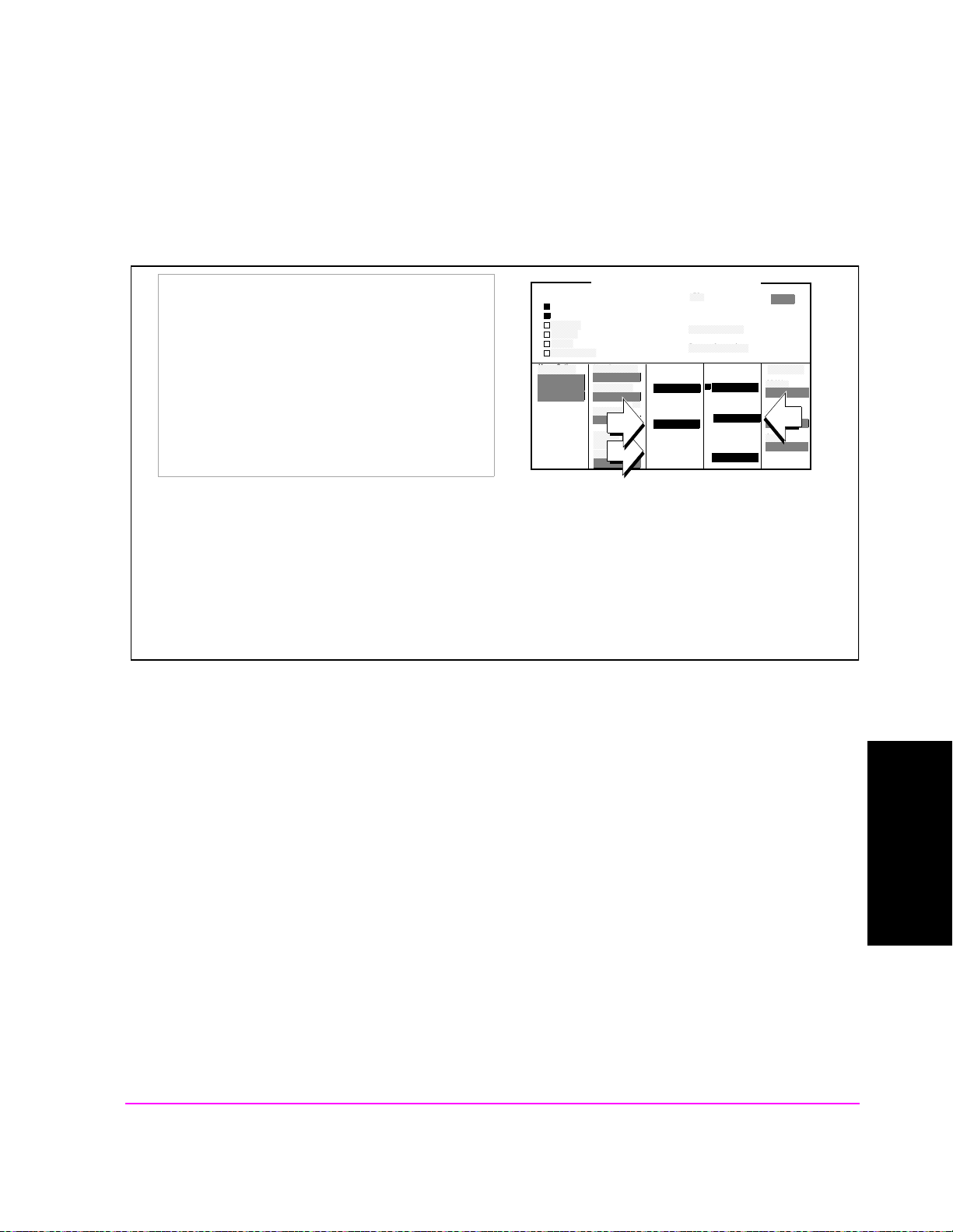
7. Change Traffic Data Rate to Half.
Chapter 3, Mobile Station CDMA Tests
FER (Frame Error Rate)
1. Set the Data Rate field to Half.
2. Set the Traffic field to
−18.6 dB (reducing
power by one-half).
Test Status
Connected
Svc Opt 2
Testing
Passed
Failed
Max Frames
Meas Cntl
Single/Cont
Arm
Disarm
CDMA CELLULAR MOBILE RECEIVER TEST
FER
Errors Counted
Frames Counted
Max Frames
On/Off
Confidence
FER Specs
Display
Interim
Results
Yes/No
95.00
3.00
%
%
Traffic
Data Mode
Svc Opt 2
Data Rate
Full
Eb/Nt
3.77
Sector A
Power
Traffic
-16.3
AWGN
-75.0
dBm/BW
-74.0
dbm/BW
dB
%
To Screen
CDMA
CALL CNTL
Analog
RX TEST
Cnfig
PRNT CNFG
Changing Data Rate to "Half" increas e d Eb/Nt by 3 dB. Here’s why: To transmit half-rate data, a CDMA base
station transmits each information bit two times. This doubles the energy per bit, E
(which is 3 dB), the Traffic channel was lowered by 3 dB.
E
b/Nt
. To offset this increase in
b
Whenever the data rate is lowered, the test standards will always specify a lower the Traffic channel level to
maintain E
levels that will adequately test the sensitivity of the mobile station.
b/Nt
63
Mobile Station CDMA Tests
Chapter 3

Chapter 3, Mobile Station CDMA Tests
FER (Frame Error Rate)
8. Arm another FER measurement.
1. Select the Arm field to begin another FER test.
Measurement Overview
During this test, FER is measured with the AWGN (Additive White Gaussian
Noise) generator turned on. The relative settings of AWGN, Sector Power, and
Traffic, along with Data Rate provide a value called E
signal-to-noise ratio in analog radio test.
Test standards require FER testing at various levels of E
using the Data Rate and Traffic fields. The value you enter in the FER Spec field
provides Pass/Fail criteria for the test, which will be more stringent at higher
values of E
Because the Test Set supports the Confidence Interval
FER, the number of frames tested will typically be far less than the number of
frames entered in the Max F rames field. T his speeds up F ER tests dramatically.
b/Nt
.
Test Status
Connected
Svc Opt 2
Testing
Passed
Failed
Max Frames
Meas Cntl
Single/Cont
Arm
Disarm
CDMA CELLULAR MOBILE RECEIVER TEST
FER
Errors Counted
Frames Counted
Max Frames
Confidence
FER Spec
Display
Interim
Results
Yes/No
10000
95.00
3.00
%
%
Traffic
Data Mode
Svc Opt 2
Data Rate
Full
Eb/Nt
3.77
, which is analogous to
b/Nt
b/Nt
1
procedure for testing
%
Sector A
Power
Traffic
-16.3
AWGN
-75.0
-74.0
dBm/BW
dbm/BW
dB
To Screen
CDMA
CALL CNTL
Analog
RX TEST
Cnfig
PRNT CNFG
, which are adjusted
This test is fully described in "Demodulation of Forward Traffic Channel in
Additive White Gaussian Noise," found in standards such as TIA/EIA/IS-98-A or
J-STD-018.
1. Refer to Appendix A in the appropriate test standard for a description of Confidence
Interval testing.
64

4
Mobile Station Analog Tests
65
Mobile Station Analog Tests
Chapter 4

Chapter 4, Mobile Station Analog Tests
List of Analog Tests
List of Analog Tests
• "Performing a CDMA to Analog Handoff" on page 67
• "Performing an Analog Call" on page 71
• "Transmitter Measurements (no audio connections required)" on page 75
• "Receiver Audio Distortion and Hum and Noise (requires audio connections)" on
page 78
• "Transmitter Audio Distortion and Hum and Noise (requires audio connections)"
on page 83
66

Performing a CDMA to Analog Handoff
The HP 8924E has the capability t o simulate both a CDMA cell site and an anal og
cell site. This makes it possible to perform a handoff from a CDMA traffic
channel to an analog voice channel. This type of handoff allows you to easily
change from CDMA testing to analog testing.
The following conditions are required for a successful handoff:
❒ You must know the mobile station’s system type (AMPS, NAMPS).
❒ A CDMA call must be connected.
❒ The mobile station must be programmed to allow analog operation.
For some of the following analog tests, you will need audio connections from the
mobile station’s microphone and earpiece to the Test Set’s AUDIO OUT and
AUDIO IN, respectively.
Chapter 4, Mobile Station Analog Tests
Performing a CDMA to Analog Handoff
1. Select an analog system for handoffs.
1. Select the CDMA CALL CONTROL screen.
2. Set the System Type field to your mobile
station’s analog system type.
Call Status
Transmitting
Registering
Page Sent
Access Probe
Connected
Softer Handoff
Hard Handoff
RF Channel
384
Register
RF Chan Std
MS AMPS
Handoff
Execute
System Type
AMPS
Channel
1
SAT
5970 Hz
Pwr Level
4
CDMA CALL CONTROL
MS FER Report
Avg Power
Traffic
Data Mode
Svc Opt 1
Data Type
Echo
Echo Delay
2 Seconds
Avg Power
Power Zero
----
MS ID
Phone Num
5099214001
MS Database
ESN
1234
Sector A
Power
-75.0
dBm/BW
%
dBm
To Screen
CDMA
CALL CNTL
Analog
RX TEST
Cnfig
PRNT CNFG
Mobile Station Analog Tests
67
Chapter 4
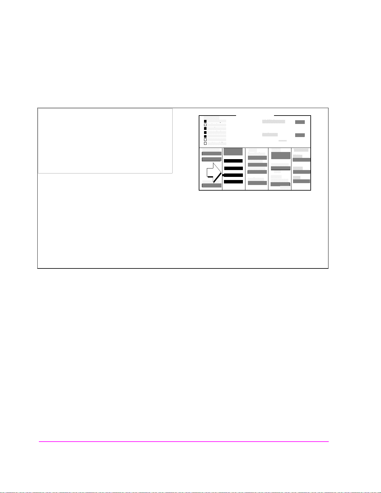
Chapter 4, Mobile Station Analog Tests
Performing a CDMA to Analog Handoff
2. Set up handoff parameters. (Optional)
Handoff
Execute
System Type
AMPS
Channel
1
SAT
5970 Hz
Pwr Level
4
CDMA CALL CONTROL
MS FER Report
Avg Power
Traffic
Data Mode
Svc Opt 1
Data Type
Echo
Echo Delay
2 Seconds
Avg Power
Power Zer o
----
MS ID
Phone Num
5099214001
MS Database
ESN
1234
Sector A
Power
-75.0
dBm/BW
%
dBm
To Screen
CDMA
CALL CNTL
Analog
RX TEST
Cnfig
PRNT CNFG
1. Set the Channel, SAT, DSAT, or Pwr Level
fields as needed to specify handoff parameters.
Call Status
Transmitting
Registering
Page Sent
Access Probe
Connected
Softer Handoff
Hard Handoff
RF Channel
384
Register
RF Chan Std
MS AMPS
These three fields provide the Test Set with information about how to set up th e simulated analog cell site for
the handoff to an analog voice channel. The three fields are:
• Channel: The analog voice channel that will be allocated for CDMA to analog handoffs.
• SAT: The supervisory audio tone th at the Test Set will transmit, and the mobile s tation will transpond.
• Pwr Level: The power level to be transmitted by the mobile station after the handoff is successful, referred
to as VMAC (voice mobile attenuation code).
68

3. Execute the CDMA to analog handoff.
Chapter 4, Mobile Station Analog Tests
Performing a CDMA to Analog Handoff
1. Select Execute.
The Access annunciator should light for a few
seconds, then the Connect annunciator will
light, indicating the handoff is successful.
Call Status
Transmitting
Registering
Page Sent
Access Probe
Connected
Softer Handoff
Hard Handoff
RF Channel
384
Register
RF Chan Std
MS AMPS
Display
Data/Meas
Active
Register
Page
Access
Connect
Active
Register
Page
Handoff
Release
Order
Chng PL 0
MS ID
Phone Num
5099214001
Handoff
Execute
System Type
AMPS
Channel
1
SAT
5970 Hz
Pwr Level
4
System Type
AMPS
Cntrl Chan
321
Amplitude
-50.0
SID
231
CDMA CALL CONTROL
Traffic
Data Mode
Svc Opt 1
Data Type
Echo
Echo Delay
2 Seconds
Avg Power
Power Zer o
CALL CONTROL
Voice Channel Assignment
Chan: 212
Pwr Lvl: 4
dBm
SAT: 5970
MS FER Report
Avg Power
MS ID
Phone Num
5099214001
MS Database
ESN
1234
Sector A
Power
212
4
5970Hz
-75.0
----
dBm/BW
%
dBm
To Screen
CDMA
CALL CNTL
Analog
RX TEST
Cnfig
PRNT CNFG
To Screen
CDMA
CALL CNTL
Analog
RX TEST
Cnfig
PRNT CNFG
When a CDMA to analog handoff is attempted, the Test Set reconfigures itself as an analog cell site, and
displays the CALL CONTROL screen. This is the screen that controls analog call processing.
69
Mobile Station Analog Tests
Chapter 4

Chapter 4, Mobile Station Analog Tests
Performing a CDMA to Analog Handoff
Problem Solving
❒ In some cases, background noise can inhibit supervisory audio tone (SAT) detection
during call setup. If the mobile station does not provide a way to mute the microphone,
set the Sat Tol field to Wide on the CALL CONFIGURE screen. Then, attempt the
handoff again.
Procedure Overview
The CDMA to Analog handoff is performed by selecting the Execute field on the
CDMA CALL CONTROL screen when a CDMA call is connected. The Test Set
reconfigures it self as a n analog cel l site a nd hands the mobile s tation of f to a vo ice
channel on the system type specified.
70

Performing an Analog Call
This procedure is optional. If you would like to skip this procedure and begin
testing now, turn to
on page 75
The same general conditions for performing a CDMA call also apply to
performing an analog call.
does not connect.
.
Chapter 4, Mobile Station Analog Tests
Performing an Analog Call
"Transmitter Measurements (no audio connections required)"
See "Problem Solving Checklist" in chapter 2 if the call
71
Mobile Station Analog Tests
Chapter 4

Chapter 4, Mobile Station Analog Tests
Performing an Analog Call
1. Enter the mobile station’s control channel number.
-50.0
321
dBm
231
CALL CONTROL
Voice Channel Assignment
Chan: 212
Pwr Lvl: 4
SAT: 5970
5970Hz
212
To Screen
CDMA
CALL CNTL
Analog
4
RX TEST
Cnfig
PRNT CNFG
1. Set the Cntrl Chan field to one of the control
channel numbers that the mobile station is
programmed to find service on.
Display
Data/Meas
Active
Register
Page
Access
Connect
Active
Register
Page
Handoff
Release
Order
Chng PL 0
MS ID
Phone Num
5099214001
System Type
AMPS
Cntrl Chan
Amplitude
SID
When attempting to acquire analog service, the mobile station receiver scans its “preferred system” control
channels when it is turned on, or when a call is released. By decoding the data on the control channel, the
mobile station can determine th e cell ula r system I.D. and determine if it is roaming.
In North American FM systems, System A control channels are 313-333, and System B control channels are
334-354.
2. End the current call (if the Connected annunciator is lit).
-50.0
321
dBm
231
CALL CONTROL
Voice Channel Assignment
Chan: 212
Pwr Lvl: 4
SAT: 5970
5970Hz
212
To Screen
CDMA
CALL CNTL
Analog
4
RX TEST
Cnfig
PRNT CNFG
1. Select Release.
The Active annunciator should now be lit.
Display
Data/Meas
Active
Register
Page
Access
Connect
Active
Register
Page
Handoff
Release
Order
Chng PL 0
MS ID
Phone Num
5099214001
System Type
AMPS
Cntrl Chan
Amplitude
SID
The mobile station receiver will scan its “preferred system” control channels when the call is released (or
power is turned on). It shou ld l ock to the T est Set’ s con trol cha nnel a nd conti nue to dis play that it ha s ser vice.
If the mobile station loses service, increase the Amplitude field setting to -30 dBM, and cycle power to the
mobile station. If this doesn’t work, refer to "Problem Solving Checklist" in chapter 2
72
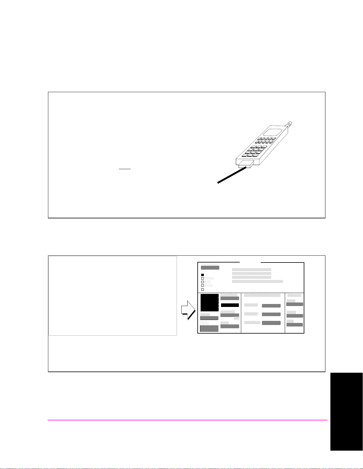
3. Dial 1234 on the mobile station’s handset, then press SEND.
You can use any sequence of numbers to perform this step.
1,2,3,4was chosen simply for convenience.
The Test Set’s Access annunciator will light, then the Connect
annunciator will light.
After a mobile station has successfully originated a call, you
will see the mobile station’s identification displayed on the
CALL CONTROL scree n (if Data
field.
Another way to retrieve the mobile station identification is by
selecting the Register field when the Active annunciator is lit.
is selected in the Display
Chapter 4, Mobile Station Analog Tests
Performing an Analog Call
4. End the current call.
1. Select Release.
The Active annunciator should now be lit.
Display
Data/Meas
Active
Register
Page
Access
Connect
Active
Register
Page
Handoff
Release
Order
Chng PL 0
MS ID
Phone Num
5099214001
System Type
AMPS
Cntrl Chan
321
Amplitude
-50.0
SID
231
CALL CONTROL
Voice Channel Assignment
Chan: 212
Pwr Lvl: 4
dBm
SAT: 5970
5970Hz
212
To Screen
CDMA
CALL CNTL
Analog
4
RX TEST
Cnfig
PRNT CNFG
Mobile Station Analog Tests
Chapter 4
73

Chapter 4, Mobile Station Analog Tests
Performing an Analog Call
5. Page the mobile station.
1. Select Page in the field shown.
The mobile station should ring.
2. Press SEND on the mobile station handset.
The Connect annunciator should now be lit.
Display
Data/Meas
Active
Register
Page
Access
Connect
Active
Register
Page
Handoff
Release
Order
Chng PL 0
MS ID
Phone Num
5099214001
System Type
AMPS
Cntrl Chan
321
Amplitude
-50.0
SID
231
CALL CONTROL
Voice Channel Assignment
Chan: 212
Pwr Lvl: 4
dBm
SAT: 5970
5970Hz
212
To Screen
CDMA
CALL CNTL
Analog
4
RX TEST
Cnfig
PRNT CNFG
74

Chapter 4, Mobile Station Analog Tests
Transmitter Measurements (no audio connections required)
Transmitter Measurements (no audio connections required)
1. Display analog measurements.
1. Set the Display field to Meas.
Display
Data/Meas
Active
Register
Page
Access
Connect
Active
Register
Page
Handoff
Release
Order
Chng PL 0
MS ID
Phone Num
5099214001
System Type
AMPS
Cntrl Chan
Amplitude
SID
TX Freq Error
-0.125
TX Power
0.0838
321
-50.0
dBm
231
CALL CONTR OL
kHz
FM Deviation
AF Freq
W
Voice Channel Assignment
Chan: 212
Pwr Lvl: 4
SAT: 5970
5970Hz
2.196
5.96943
212
4
kHz
kHz
To Screen
CDMA
CALL CNTL
Analog
RX TEST
Cnfig
PRNT CNFG
The measurements that are displayed on the CALL CONTROL screen indicate the mobile station’s RF power,
(TX Power) carrier frequency error (TX Freq Error), Supervisory Audio Tone (SAT) frequency (AF Freq),
and SAT level (FM Deviation).
75
Mobile Station Analog Tests
Chapter 4
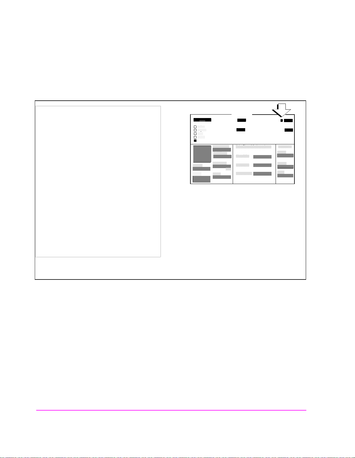
Chapter 4, Mobile Station Analog Tests
Transmitter Measurements (no audio connections required)
2. Set measurement limits for FM Deviation.
1. Position the cursor next to the FM Deviation
units field.
2. Press then release the SHIFT key, then press the
down-arrow key to select LO LIMIT.
3. Enter 1.8 kHz using the DATA keys and then
press the knob.
4. Press then release the SHIFT key, then press the
up arrow key to select HI LIMIT.
Display
Data/Meas
Active
Register
Page
Access
Connect
Active
Register
Page
Handoff
Release
Order
Chng PL 0
MS ID
Phone Num
5099214001
System Type
AMPS
Cntrl Chan
Amplitude
SID
TX Freq Error
-0.125
TX Power
0.0838
321
-50.0
dBm
231
CALL CONTR OL
kHz
FM Deviation
AF Freq
W
Voice Channel Assignment
Chan: 212
Pwr Lvl: 4
SAT: 5970
5970Hz
2.196
Lo Hi
5.96943
212
4
To Screen
CDMA
CALL CNTL
Analog
RX TEST
Cnfig
PRNT CNFG
5. Enter 2.2 kHz using the DATA keys and then
press the knob.
The Lo and Hi annunciators will appear below the
displayed value of FM Deviation.
The limit values given in this procedure are based
on an FM Deviation of approximately
2 kHz (peak+) deviation.
If the displayed value for FM Deviation exceeds either limit, the Test Set will beep and the corresponding
annunciator will become brighter and flash. Press the ME AS RESET key to reset limit detection.
kHz
kHz
76
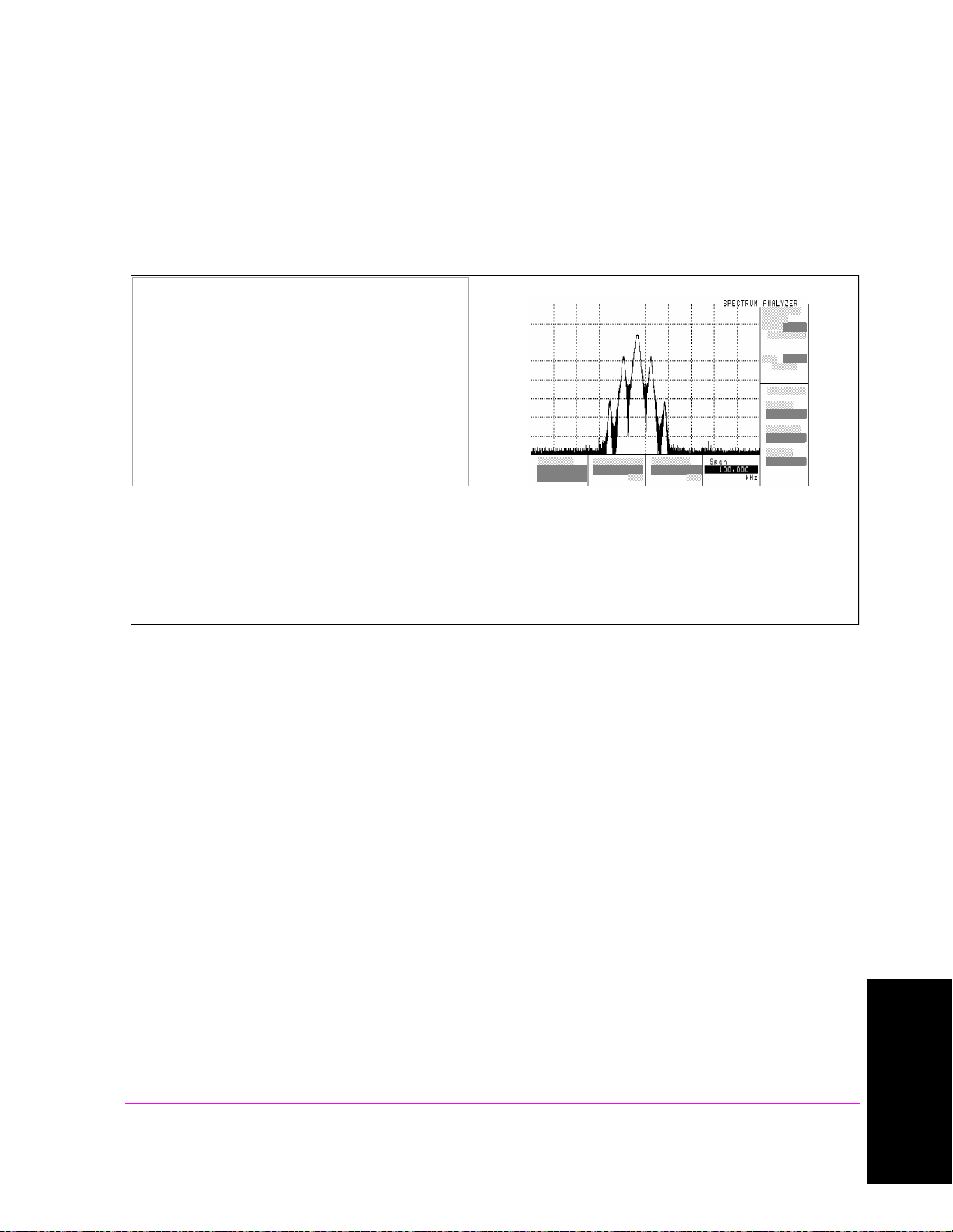
Chapter 4, Mobile Station Analog Tests
Transmitter Measurements (no audio connections required)
3. Access the Spectrum Analyzer (opt 012 only).
1. Press the SPEC ANL key.
2. Set the Span field to 100 kHz.
The Spectrum Analyzer is automatically tun e d to the mobile station transmitter frequency.
The resolution bandwidth of the Spectrum Analyzer is coupled to the frequency span setting. With Span set to
100 kHz, the resolution bandwidth is 1 kHz.
Mobile Station Analog Tests
77
Chapter 4
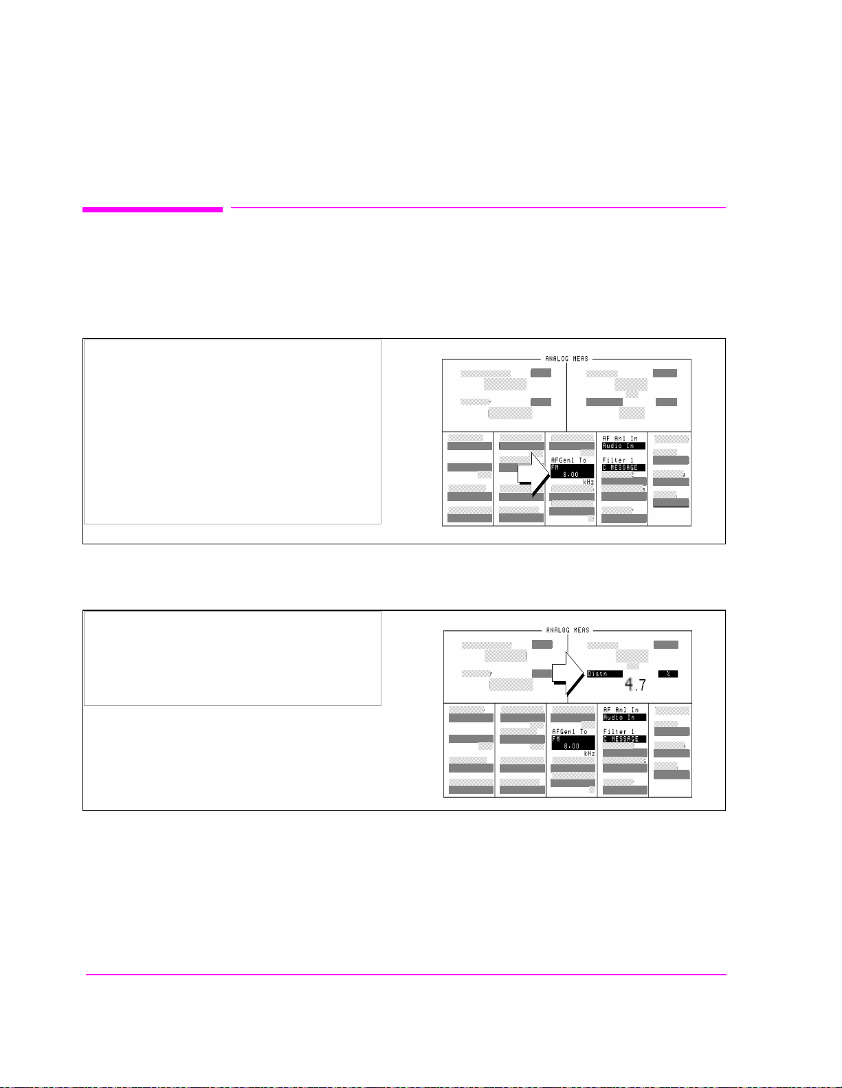
Chapter 4, Mobile Station Analog Tests
Receiver Audio Distortion and Hum and Noise (requires audio connections)
Receiver Audio Distortion and Hum and Noise (requires au dio
connections)
1. Set up the receiver distortion measurement.
1. Press the ANLG MEAS key.
2. Set the FM level field to 8 kHz.
3. Set the AF Anl In field to Audio In.
4. Set the Filter 1 field to C MESSAGE.
2. Make the receiver distortion measurement.
1. Select Distn in the field shown.
The value displayed should be less than 5%
78
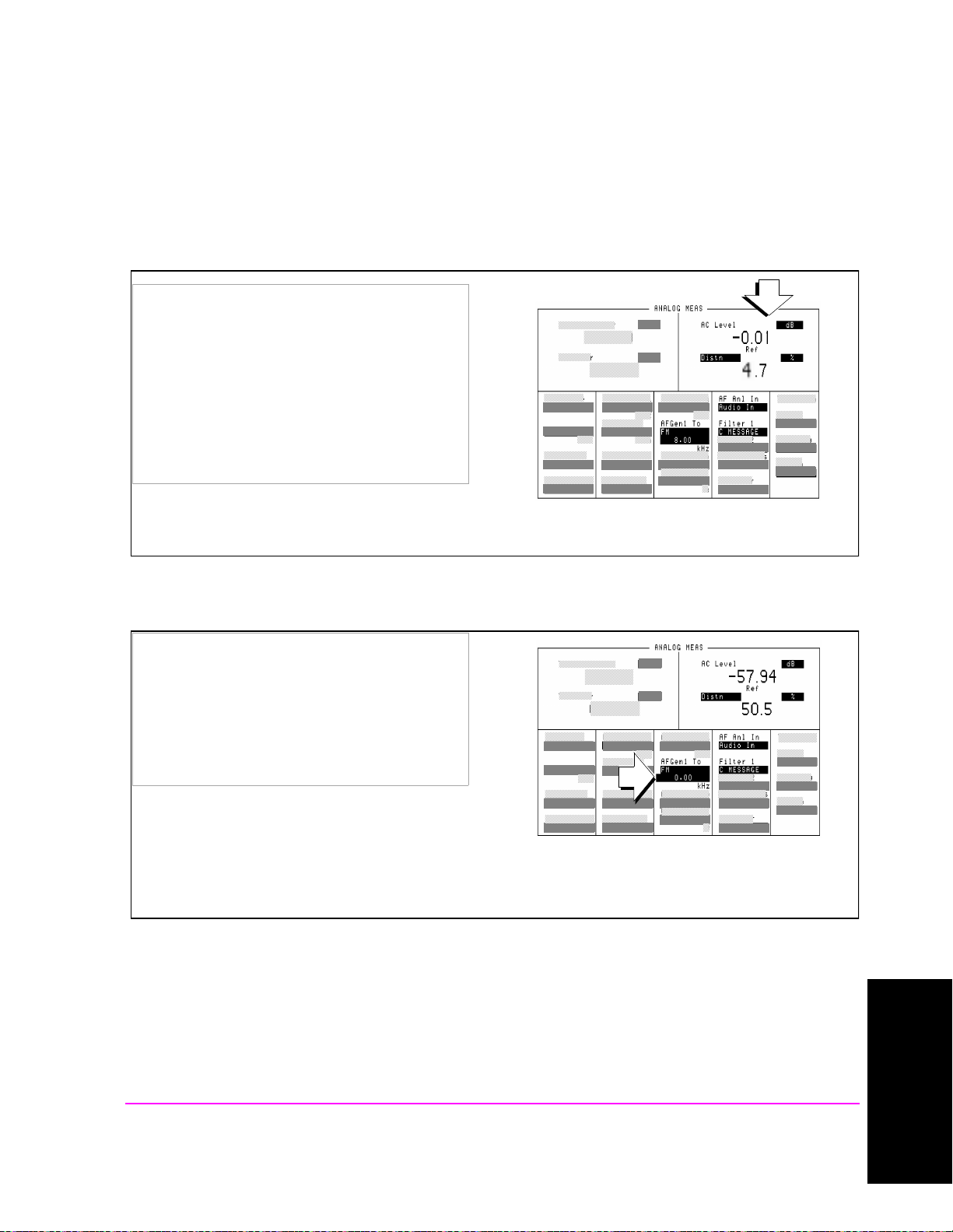
Receiver Audio Distortion and Hum and Noise (requires audio connections)
3. Set up the receiver hum and noise measurement.
1. Position the cursor in front of the AC Level
field.
2. Press then release the blue SHIFT key, then
press the INCR ÷10 key
3. Press the knob to set a 0 dB reference.
The AC Level field should display a value near
0dB.
Chapter 4, Mobile Station Analog Tests
4. Make the receiver hum and noise measurement.
1. Position the cursor in front of the audio
frequency generator field. Press the ON/OFF
key.
The AC Level field will display the FM hum and
noise level. It should be at least 32 dB lower
than the reference level.
Turning off the audio frequency generator allowed the Test Set to display the ratio of FM without modu lation
(residual FM) to FM with the test signal applied, using the AC level reference value.
Mobile Station Analog Tests
Chapter 4
79
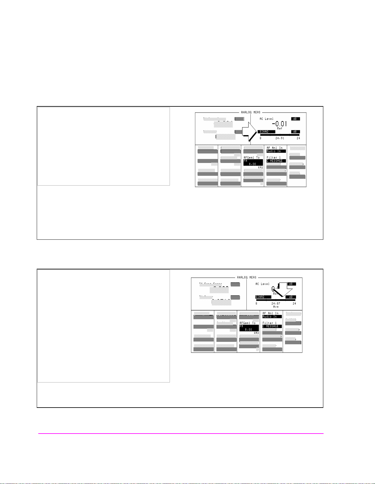
Chapter 4, Mobile Station Analog Tests
Receiver Audio Distortion and Hum and Noise (requires audio connections)
5. Set up the receiver RF sensitivity measurement.
1. Press the ON/OFF key again to turn the audio
frequency generator back on.
2. Select SINAD.
The display should change fr om di git al reado ut to
a meter format.
6. Turn on the averaging feature.
1. Position the cursor in front of the uni t s field fo r
the SINAD measurement.
2. Press then release the SHIFT key, then press the
INCR ×10 key to select AVG.
3. Using the DATA keys, enter 10 and press the
knob.
The Avg annunciator should be displayed below
the SINAD meter.
Averaging smooths out measurements that have rapid fluctuations, like the SINAD measurement.
80

Receiver Audio Distortion and Hum and Noise (requires audio connections)
7. Make the receiver RF sensitivity measurement.
1. Select the Amplitude field.
2. Enter −100 using the DATA keys and press the
knob.
3. Press the INCR SET key and enter 0.5 d B usin g
the DATA keys, then press the knob.
4. Press and release the SHIFT key, then the
RECALL (SAVE) key. Enter SINAD using the
letters in the Save: menu, then select Done (at
the top of the Save menu).
4. Slowly turn the knob counterclockwise to adjust
Amplitude until 12 dB SINAD is displayed on
the meter.
Chapter 4, Mobile Station Analog Tests
If four dashes appear in the TX Freq Error field,
the Amplitude was lowered t oo qui ck ly an d t he
call was dropped.
Re-establish the call using the CALL CONTROL
screen. Press the RECALL key and select
SINAD from the Recall: menu.
The Test Set should be ready to measure SINAD
again.
12 dB SINAD will be obtained at a very low signal level to the mobile station, probably below -110 dBm. For
this reason, it is important to tu rn the knob slowly while watching the SINAD meter for changes.
Mobile Station Analog Tests
Chapter 4
81

Chapter 4, Mobile Station Analog Tests
Receiver Audio Distortion and Hum and Noise (requires audio connections)
Measurement Overview
Receiver Audio Harmonic Distortion is measured with the Test Set providing an
FM signal to the mobile station, modulated by a test tone from the Test Set’s
audio frequency generator. (A SAT tone is also present on the RF signal). To
measure distortion, the audio signal from the mobile station’s earpiece (receiver
output) is cabled to the Test Set’s AUDIO IN connector. The Test Set’s audio
analyzer measures th e level of the audio output, then notches out the test to ne a nd
measures only the RMS harmonic content produced by the audio signal.
Distortion is then displayed as the percentage of mobile station receiver output
level that was due to the harmonic content.
Typically, Audio Harmonic Distortion should be less than 5%.
Receiver hum and noise uses essentially the same setup as distortion, except that
the modulation source is turned off, and residual FM is measured. The hum and
noise measurement is the ratio of AC leve l from the mobile station’s receiver
without modulation to AC level with modulation.
Typically transmitter Hum and Noise should be at least 32 dB below levels with
modulation on.
SINAD, a measure of receiver sensitivity, also uses essentially the same setup as
distortion, except the RF amplitude to the mobile station’s antenna input is
lowered until 12 dB SINAD is rea che d. SI NAD mea sur emen ts are the ratio of the
test signal plus noise and distortion components to just the noise and distortion.
82
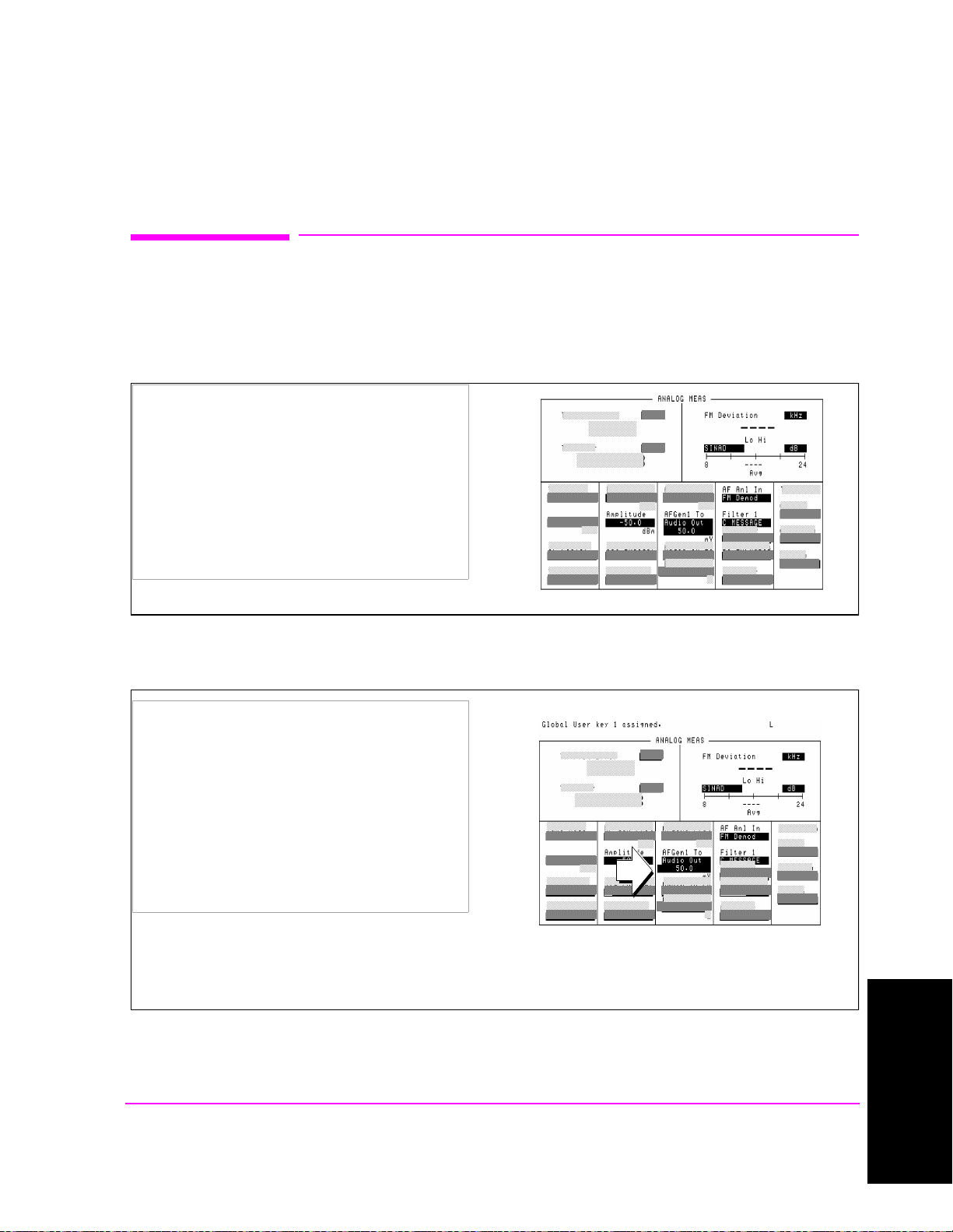
Chapter 4, Mobile Station Analog Tests
Transmitter Audio Distortion and Hum and Noise (requires audio connections)
Transmitter Audio Distortion and Hum and Noise (requires audio
connections)
1. Set up the transmitter distortion measurement.
1. Set the Amplitude field to −50.0 dBm.
2. Set the AFGen1 To field to Audio Out.
3. Set the AF Anl In field to FM Demod.
4. Set the Filter 1 field to C Message.
2. Define a USER key for adjusting audio level.
1. Position the cursor in front of the audio
generator level field as shown.
2. Press then release the blue SHIFT key, then
press K4 (ASS IGN).
3. Press then release the blue SHIFT key again,
then press K1 (K1’).
The message “Global User key 1 assigned” should
be displayed at the top of the screen.
The Audio Generator level field can now be called from any screen.
Mobile Station Analog Tests
Chapter 4
83
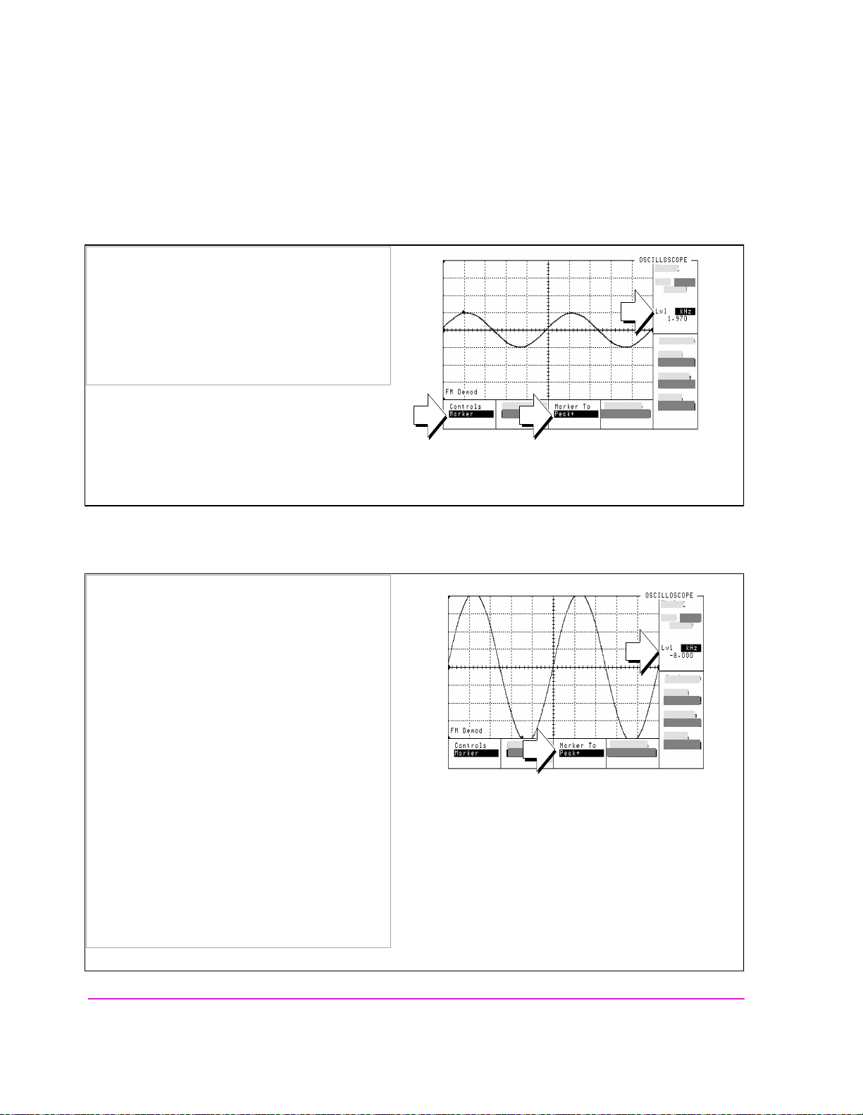
Chapter 4, Mobile Station Analog Tests
Transmitter Audio Distortion and Hum and Noise (requires audio connections)
3. Access the Test Set’s Oscilloscope.
1. Press the SCOPE key.
2. Set the Controls field to Marker.
3. Select the Marker To, Peak+ field.
Observe the amount of FM deviation in the Lvl
field as shown.
The Oscilloscope is automatically set to display the demodulated FM signal from the mobile station.
4. Adjust the peak frequency deviation.
1. Press then release the blue SHIFT key, then
press K1.
The AF Gen 1 Level field will appear at the top of
the display.
2. Press the knob and adjust the level until abo ut
8 kHz of deviation is observed in the Lvl field.
3. Press the knob again to de-select the AF
Generator field.
3. Select the Marker To, Peak- field.
The Peak- field should display approximately
−8 kHz of FM deviation in the Lvl field.
84
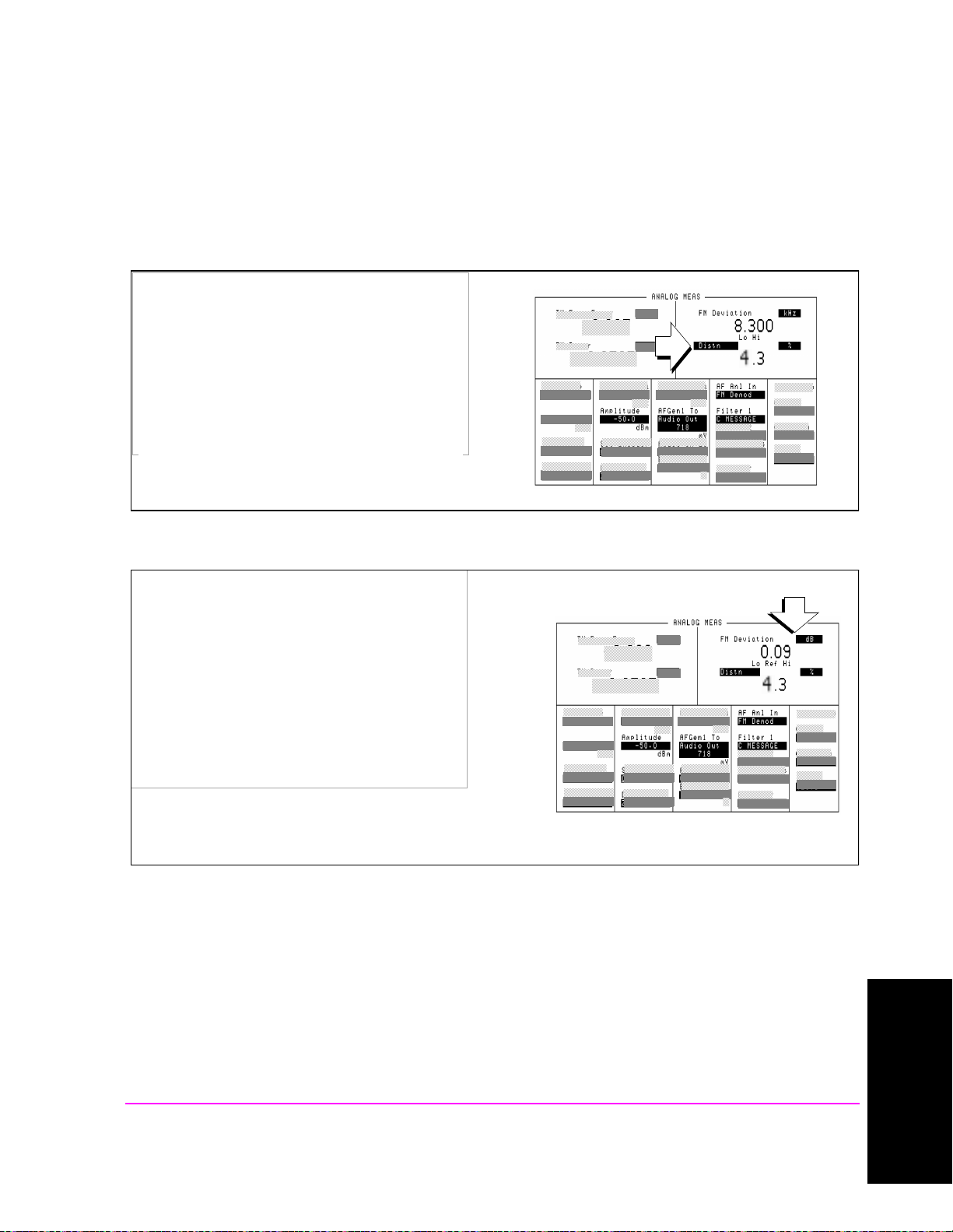
Transmitter Audio Distortion and Hum and Noise (requires audio connections)
5. Make the transmitter distortion measurement.
1. Press the PREV key to return to the ANALOG
MEAS screen.
The Hi limit annunciator should be flashing.
2. Select Distn.
Observe the value displayed next to the Distn
field. It should be less than 5%.
Chapter 4, Mobile Station Analog Tests
6. Set up the transmitter hum and noise measurement
1. Position the cursor next to the FM Deviation
field.
2. Press then release the blue SHIFT key, then
press the INCR ÷10 key.
3. Press the knob to set a 0 dB reference.
The new value displayed should be close to 0 dB.
The FM Deviation field is displayed whenever the AF Anl In field is set to FM Demod.
Mobile Station Analog Tests
85
Chapter 4
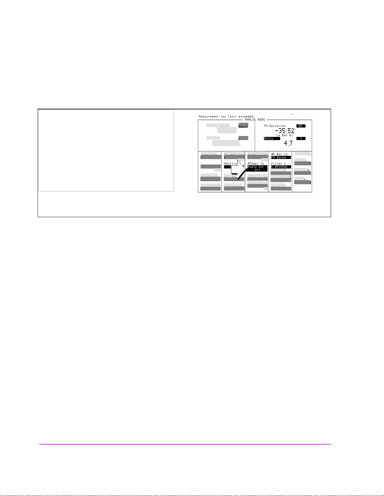
Chapter 4, Mobile Station Analog Tests
Transmitter Audio Distortion and Hum and Noise (requires audio connections)
7. Make the transmitter hum and noise measurement.
1. Position the cursor in front of the audio
frequency generator level field as sh own. Press
the ON/OFF key.
The Lo and Hi limit annunciators should be
flashing.
The FM Deviation field will display the FM hum
and noise level. It should be at least 32 dB
lower than the reference level.
Setting the 0 dB reference allowed the Test Set to display the ratio of FM without modulation (residual FM) to
FM with the test signal applied, in the FM Deviation field.
Measurement Overview
Transmitter D istortion (and Noise) is measured with a test tone adju sted to
frequency modulate the mobile station’s transmitter with a specified deviation.
The FM signal from the mobile station’s transmitter is demodulated by the Test
Set using a C-message weighted filter, and distortion and noise are measured.
Typically, distortion should be less than 5%.
Transmitter Hum and Noise is measured by modulating the mobile station’s
transmitter with a test tone adjusted to produce a specified amount of deviation.
With the signal from the mobile station’s transmitter demodulated by the Test Set
using a C-message weighted filter, the amount of deviation is recorded. To
determine the hum and noise, which is caused by residual FM, the modulation is
removed and the ratio of residual FM to FM with the test signal on is calculated.
Typically, FM Hum and Noise should be less than
−32 dB.
86

Short Message Service Tests
5
Chapter 5
Short Message Service Tests
The following SMS tests verify that the Mobile Station Under Test (Mobile
Station) is capable of receiving short messages.
Short messages can be sent:
• on the Paging/Access channels (phone has registered but is not on a traffic channel)
• on the Traffic channels (Service Option 6 or 14)
• on the Traffic channels (Service Option 1 or 32768)
All SMS procedures performed by the Test Set are mobile station terminated,
meaning that the Test Set is sending messages to the Mobile Station.
The short message feature for the Mobile Station must be activated to perform
these tests.
87

Chapter 5, Short Message Service Tests
List of CDMA SMS Tests
List of CDMA SMS Tests
"Sending Short Messages on the Paging/Access Channels" on page 89.
"Sending Short Messages on the Traffic Channels" on page 97.
88

Short Message Service Tests
Chapter 5, Short Message Service Tests
Sending Short Messages on the Paging/Access Channels
Sending Short Messages on the Paging/Access Channels
This procedure sends a short message to the Mobile Station on the Paging
channel. The Test Set verifie s tha t the Mobile Stat ion ac knowled ged re ceivi ng the
SMS message.
Chapter 5
89

Chapter 5, Short Message Service Tests
Sending Short Messages on the Paging/Access Channels
1. Register the Mobile Station.
If the Mobile Station is already registered, this step is not necessary.
See
"Setting up a Call" on page 43 if you are not familiar with how this procedure
is performed with the Test Set.
Registering the Mobile Station will ensure that it is monitoring the Test Set’s Paging channel.
90

Short Message Service Tests
Chapter 5, Short Message Service Tests
Sending Short Messages on the Paging/Access Channels
2. Optional: Clear (erase) old messages in the Mobile Station.
Access the message list and follow prompts on the
Mobile Station to erase current messages.
Chapter 5
erase.ds4
91
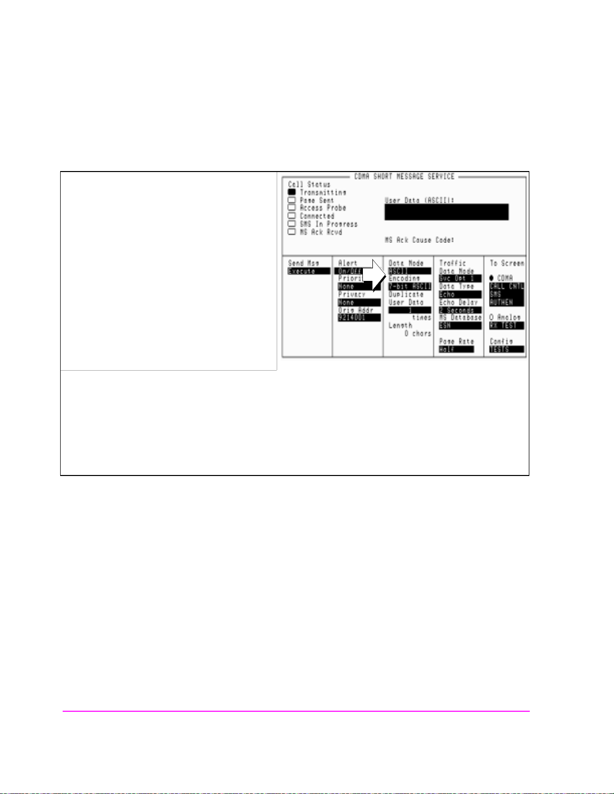
Chapter 5, Short Message Service Tests
Sending Short Messages on the Paging/Access Channels
3. Select the data format for the SMS message.
1. Select SMS from the To Screen, CDMA list to
display the CDMA SHORT MESSAGE
SERVICE screen.
2. Position the cursor in front of the Data Mode
field. Select the data format.
3. Position the cursor in front of the Encoding
field. Select an encoding type.
sms1.pcx
.The choice you make in the Data Mode field determines wh at type of characters you will enter in the User
Data field, ASCII or hexadecimal. If you select ASCII , the Test Set translates User Data according to the
ASCII code chart. If you select Hex, no translation is applied.
The Encoding field will determine if character data is encoded as either 7-bit or byte format.
92
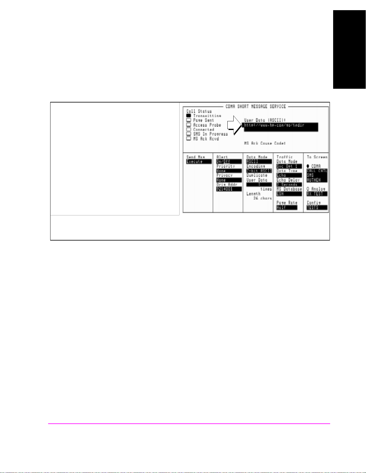
Short Message Service Tests
Sending Short Messages on the Paging/Access Channels
4. Enter a short message in the Test Set’s data field.
1. Position the cursor in front of the data field
shown.
2. Press the knob and enter a message. Select
Done when done.
Chapter 5, Short Message Service Tests
Chapter 5
sms3.pcx
93

Chapter 5, Short Message Service Tests
Sending Short Messages on the Paging/Access Channels
5. Set the Page Rate.
1. Set the Page Rate field to Full.
sms8.pcx+newfield.pcx
Setting the Page Rate field to Full provides more Paging Channel slots to send the Data Burst Message in.
94

Short Message Service Tests
6. Send the message.
1. Select the Send Msg Execute.
The SMS in Progress annunciator will light when
the message is sent, and remain lit until an
acknowledgment is received or SMS times out.
Chapter 5, Short Message Service Tests
Sending Short Messages on the Paging/Access Channels
Chapter 5
The MS Ack Rcvd will light when the Test Set
has received an an SMS Acknowledgment
message from the Mobile Station.
sms2.pcx+newfield.pcx
sms4.pcx+newfield.pcx
95

Chapter 5, Short Message Service Tests
Sending Short Messages on the Paging/Access Channels
Measurement Overview
1. "Register the Mobile Station." on page 90.
See "Setting up a Call" on page 43.
2. "Optional: Clear (erase) old messages in the Mobile Station." on page 91.
3. "Enter a short message in the Test Set’s data field." on page 93.
4. "Set the Page Rate." on page 94.
5. "Send the message." on page 95.
96

Short Message Service Tests
Sending Short Messages on the Traffic Channels
Sending Short Messages on the Traffic Channels
This procedure sends a short message to the Mobile Station on the Traffic
channels. The first message will be sent without setting up a call (Service Option
6 or 14), and the second message wil l be sent while the Mobile Stati on is on a cal l
(Service Option 1 or 32768).
Chapter 5, Short Message Service Tests
Chapter 5
97

Chapter 5, Short Message Service Tests
Sending Short Messages on the Traffic Channels
1. Register the Mobile Station.
If the Mobile Station is already registered, this step is not necessary.
See
"Setting up a Call" on page 43 if you are not familiar with how this procedure
is performed with the Test Set.
Registering the Mobile Station will ensure that it is monitoring the Test Set’s Paging channel.
98
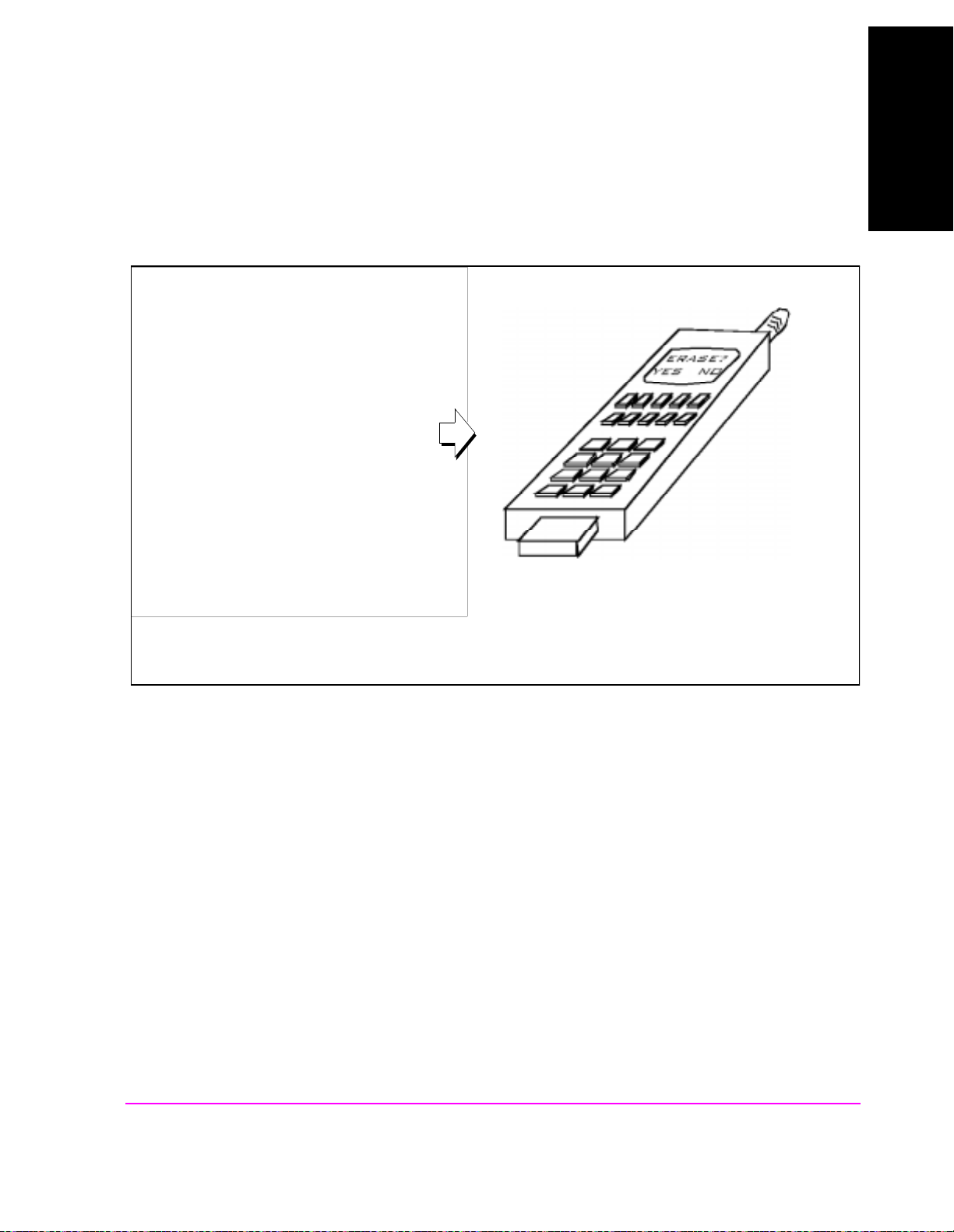
Short Message Service Tests
Chapter 5, Short Message Service Tests
Sending Short Messages on the Traffic Channels
2. Optional: Clear (erase) old messages in the Mobile Station.
Access the message list and follow prompts on the
Mobile Station to erase current messages.
Chapter 5
erase.ds4
99

Chapter 5, Short Message Service Tests
Sending Short Messages on the Traffic Channels
3. Enter a short message in the Test Set’s data field.
1. Select SMS from the To Screen, CDMA list.
2. Position the cursor in front of the data field
shown.
3. Press the knob and enter a message. Select
Done when done.
sms12.pcx
100
 Loading...