

Page 1

83236B PCS Interface
83217A CDMA Dual-Mode
Mobile Station Test Software
E8290A Point of Service Test (PoST) Software
30 MHz to 1000 MHz, 1700 MHz to 2000 MHz
The Agilent Technologies 8924C CDMA mobile
station test set provides the key set of measurements to verify the performance of dual-mode
CDMA mobile phones operating from 500 to 1000
MHz. With the Agilent Technologies 83236B PCS
Interface, the 8924C additionally offers CDMA
mobile testing from 1700 to 2000 MHz. Acting as a
calibrated, high performance CDMA base station,
the 8924C verifies not only the parametric characteristics of CDMA phones, but also the functional
aspects of phone performance.
The 8924C’s full AMPS, NAMPS, EAMPS, TACS,
NTACS, ETACS, and JTACS test capability saves
you space, cost, and training expenses by allowing
you to make both analog and CDMA digital measurements with the same instrument.
For complete call processing verification, the
8924C supports both mobile and base station initiated call connect and disconnect. Once a phone
call is established, verifying the overall functionality
of a CDMA mobile is simple using the 8924C’s
voice echo mode. For testing a variety of protocol
formats, the 8924C offers six user selectable protocol stacks: IS-95, IS-95A, TSB-74, J-STD-008, ARIB
T53, and KOREAN PCS. The 8924C also supports a
number of service options, including 9600 BPS and
14,400 BPS traffic channel configurations.
Agilent 8924C
CDMA Mobile Station Test Set
Data Sheet
Page 2

2
High Accuracy CDMA Source
for CDMA Receiver Test
Active cell site emulation in the 8924C is supplied
by Sector A. The Sector A source supports the following CDMA channels: pilot, sync, paging, traffic,
and orthogonal channel noise source (OCNS). In
addition, the 8924C has a second sector for testing
softer hand-offs. Sector B is a partial sector that
has a pilot channel, a traffic channel, and an OCNS
channel. An additive white Gaussian noise (AWGN)
Source is also included to provide the interference
generated by adjacent cells in a working CDMA
network. The 8924C measures receiver frame error
rate (FER) at all four data rates used in the CDMA
system: full, half, quarter, and one-eighth.
Confidence limit technology is used to reduce
receiver test time to an absolute minimum.
CDMA Transmitter Measurements
The 8924C provides an average power measurement based on new DSP technology. A DSP based
channel power measurement enables the 8924C to
achieve accurate low level CDMA power measurements. Access probe power measurements are also
available. The 8924C measures transmitted waveform quality by using the IS-98A/J-STD-018 recommended correlated power method, also known as
the rho (ρ) measurement. In addition, the rho
measurement reports the frequency error, modulation phase and amplitude error, and the carrier
feedthrough.
Hand-off Verification
To speed testing, the 8924C supports hard handoffs between RF channels. CDMA to analog handoffs from both cellular and PCS bands are also supported. With two configurable CDMA sectors, the
8924C can verify the ability of a CDMA mobile to
support softer hand-offs. Two 8924C test sets can
be synchronized for complete idle and soft handoff testing.
Authentication and Short
Message Service Support
The 8924C provides the necessary features for testing a CDMA mobile station’s ability to perform call
processing functions with authentication for Korea
and the United States. Also, the 8924C supports
mobile terminated SMS.
Automated Software
The new E8290A PoST (point of service test) software makes the 8924C an automated CDMA test
solution. The E8290A quickly provides accurate
phone performance and quality data at the point
of sale. This PC-based solution is very easy to use,
reduces churn, reduces NTF (no trouble found),
and improves customer care.
The 83217A CDMA dual-mode mobile station test
software can also be used to automate CDMA and
analog mobile phone measurements. The 83217A
solution does not require a PC. Rather, automatic
tests can be completely set up using the front panel
of the 8924C. Options are available to meet your
test needs for CDMA, AMPS, NAMPS, JTACS,
NTACS, U.S. PCS, and Korean PCS phones.
Specifications describe the instrument’s warranted performance and apply after a 30 minute warm-up. These
specifications are valid over the 8924C’s entire operating
environmental range unless otherwise noted. Specifications
are subject to change without notice.
Supplemental Characteristics (shown in italics) are
intended to provide additional information, useful in
applying the instrument by giving typical expected, but
non-warranted, performance.
Page 3

3
8924C ANALOG MODE SPECIFICATIONS
Call Processing Functionality
Standards: AMPS, NAMPS, TACS, JTACS,
and NTACS
Registration Support: Zone Registration
Call Control: BS call originate and disconnect,
MS call originate and disconnect
Authentication: Registration, paging, origination,
SSD update, and unique challenge
Orders: Power levels 0 through 7, maintenance,
and alert
Hand-off Support: Hand-off to new frequency,
between narrow channel and wide channel
Signal Generator
RF Frequency
Range:
Standard: 30 MHz to 1000 MHz
With the 83236B:
800 MHz to 960 MHz
1710 MHz to 1785 MHz
1805 MHz to 1910 MHz
1930 MHz to 1990 MHz
Usable from 1700 to 1999.999999 MHz
Accuracy and Stability: Same as reference oscillator
±0.015 Hz
Switching Speed: <150 ms to be within 100 Hz of
carrier frequency
Resolution: 1 Hz
Output
RF In/Out Connector
Level Range:
Standard: -127 dBm to -10.5 dBm into 50 Ω
With the 83236B: -130 dBm to -20 dBm into 50 Ω
Level Accuracy:
Standard: ±1.2 dB (Level ≥-127 dBm)
Typically ±1.0 dB for all levels
With the 83236B:
±1.8 dB, at 25° C ±10° C
±2.0 dB, at 0° C to 55° C
±1.0 dB typically
Reverse Power:
Standard: 3 W
With the 83236B: 10 W
SWR:
Standard: <1.5:1
With the 83236B: <1.2:1
Duplex Out/RF Out Only Connector
Level Range:
Standard: -127 dBm to +3.5 dBm into 50 Ω
With the 83236B: -130 dBm to -10 dBm into 50 Ω
Level Accuracy:
Standard: ±1.0 dB
With the 83236B:
±1.8 dB, at 25 °C ±10 °C
±2.0 dB, at 0 °C to 55 °C
±1.0 dB typically
Reverse Power: 200 mW maximum
SWR:
Standard: <2.0:1 (level <-7.5 dBm)
With the 83236B: <1.6:1
Resolution: 0.1 dB (setable in 0.01 dB increments)
Spectral Purity
All specifications are for ≤-2.5 dBm output level
at Duplex Out or ≤-16.5 dBm output level at RF
In/Out
Harmonics: <-30 dBc
Non-Harmonic Spurious: <-60 dBc (at >5 kHz offset
from carrier)
Residual FM (CCITT, rms):
Standard:
<7 Hz for 500 MHz <fc≤1000 MHz
<4 Hz for 250 MHz ≤fc≤500 MHz
<7 Hz for 30 MHz ≤fc<250 MHz
With the 83236B:
<7 Hz for 810 MHz ≤fc≤960 MHz
<10 Hz for 1710 MHz ≤fc≤1990 MHz
SSB Phase Noise:
Standard: <-116 dBc/Hz (for >20 kHz offsets at
a 1000 MHz carrier frequency)
With the 83236B: <-100 dBc/Hz at >20 kHz offsets
FM
Maximum FM Deviation (rates >25 Hz):
Standard:
100 kHz; 30 to <249 MHz
50 kHz; 249 to <501 MHz
100 kHz; 501 to 1000 MHz
With the 83236B:
100 kHz; 800 MHz to 960 MHz, 1710 MHz to
1785 MHz, 1805 MHz to 1910 MHz,
1930 MHz to 1990 MHz
FM Rate (1 kHz reference):
Internal: DC to 25 kHz (1 dB BW)
External:
AC Coupled: 20 Hz to 75 kHz (typical -3 dB BW)
DC Coupled: DC to 75 kHz (typical -3 dB BW)
FM Accuracy (1 kHz rate):
≤10 kHz deviation: ±3.5% of setting ±50 Hz
>10 kHz deviation ±3.5% of setting ±500 Hz
Page 4

4
FM Distortion (THD+Noise, 0.3 to 3 kHz BW):
<0.5 % at >4 kHz deviation and 1 kHz rate
Center Frequency Accuracy in DC FM Mode (external
source impedance <1 kΩ): ±500 Hz (after DCFM
zero), typically ±50 Hz
External Modulation Input Impedance: 600 Ω nominal
Resolution:
50 Hz for <10 kHz deviation
500 Hz for ≥10 kHz deviation
Audio Source (both internal sources)
Frequency
Range: dc to 25 kHz
Accuracy: 0.025 % of setting
Resolution: 0.1 Hz
Output Level
Range: 0.1 mV to 4 Vrms
Maximum Output Current: 20 mA peak
Output Impedance: <2.5 Ω (at 1 kHz)
Accuracy: ±2% of setting plus resolution
Residual Distortion (THD + Noise, level ≥200 mVrms):
<0.125 %; 20 Hz to 25 kHz in an 80 kHz BW
Resolution:
Level ≤0.01V: ±50 µV
Level ≤0.1V: ±0.5 mV
Level ≤1V: ±5 mV
Level <10V: ±50 mV
Offset in DC Coupled Mode: <50 mV
RF Analyzer
RF Frequency Measurement
Measurement Range:
Standard: 30 MHz to 1000 MHz
With the 83236B:
800 MHz to 960 MHz
1710 MHz to 1785 MHz
1805 MHz to 1910 MHz
1930 MHz to 1990 MHz
Usable from 1700 to 1999.999999 MHz
Level Range:
Standard:
RF In/Out: -10 dBm to +35 dBm (0.1 mW to 3 W)
ANT In: -36 dBm to +20 dBm
With the 83236B:
RF In/Out: -10 dBm to +40 dBm (0.1 mW to 10 W)
Accuracy: ±1 Hz plus timebase accuracy
Minimum Resolution: 1 Hz
RF Power Measurement
Note: To achieve the specified accuracy when
measuring power at the RF In/Out port, the internal signal generator level must be 40 dB below
the measured power or less than -20 dBm at the
Duplex output port.
Frequency Range:
Standard: 30 MHz to 1000 MHz
With the 83236B:
800 MHz to 960 MHz
1710 MHz to 1785 MHz
1805 MHz to 1910 MHz
1930 MHz to 1990 MHz
Input Connector: RF In/Out connector only
Measurement Range:
Standard: -10 dBm to +35 dBm (0.1 mW to 3 W)
With the 83236B: -13 dBm to +40 dBm (50 µW to 10 W)
Accuracy (after power meter zero):
Standard:
±5% of reading ±1 µ W from 15° C to 35° C
±10% of reading ±1 µ W from 0° C to 55° C
With the 83236B:
±5% of reading ±2.5 µ W at 23° C ±10° C
±10% of reading ±2.5 µ W
SWR:
Standard: <1.5:1
With the 83236B: <1.2:1
Resolution:
Standard:
Power <10W: 1 mW
Power <100 mW: 0.1 mW
Power <10 mW: 0.01 mW
With the 83236B: 0.01 dB or 10 µW
FM Measurement
Frequency Range:
Standard: 30 MHz to 1000 MHz
With the 83236B:
800 MHz to 960 MHz
1710 MHz to 1785 MHz
1805 MHz to 1910 MHz
1930 MHz to 1990 MHz
Deviation Range: 20 Hz to 75 kHz
Sensitivity: 2 µV (15 kHz IF BW, High Sensitivity
Mode, 0.3 to 3 kHz BW),1Typically <1 µV (12 dB
SINAD, fc≥30 MHz)
1. Possible degradation in the 1700 to 1999 MHz bandwidth.
Page 5

5
Accuracy (20 Hz to 25 kHz rates, deviation ≤25 kHz): ±4 %
of reading plus residual FM and noise contribution
Bandwidth (3 dB): 2 Hz to 70 kHz (DCFM measurements also available)
THD+Noise: <1% for ≥5 kHz Deviation and 1 kHz
rate in a 0.3 to 3 kHz BW
1
Input Level Range for Specified Accuracy:
Standard:
-28 to +35 dBm at RF In/Out (1.6 µW to 3 W)
-50 to +14 dBm at Ant In
With the 83236B: -36 dBm to +40 dBm
Residual FM and Noise (0.3 to 3 kHz, rms):
Standard: <7 Hz
With the 83236B: <10 Hz
Resolution:
Deviation <10 kHz: 1 Hz
Deviation ≥10 kHz: 10 Hz
Spectrum Analyzer
Frequency Range: (Center frequency coupled to RF
Analyzer setting)
Standard: 30 MHz to 1000 MHz
With the 83236B:
800 MHz to 960 MHz
1710 MHz to 1785 MHz
1805 MHz to 1910 MHz
1930 MHz to 1990 MHz
Frequency Span/Resolution Bandwidth (coupled)
Standard:
Span Bandwidth
<50 kHz 300 Hz
<200 kHz 1 kHz
<1.5 MHz 3 kHz
<18 MHz 30 kHz
≥18 MHz 300 kHz
Plus full span capability
With the 83236B:
Span Bandwidth
<50 kHz 300 Hz
<200 kHz 1 kHz
<1.5 MHz 3 kHz
Display: Log with 10 dB/division, 2 dB/division,
or 1 dB/division
Display Range: 80 dB
Reference Level Range: +50 to -50 dBm
Residual Responses: <-70 dBm (no input signal,
0 dB attenuation)
Image Rejection: >50 dB
Non-harmonic Spurious Responses: >70 dB (for input
signals ≤−30 dBm)
Level Accuracy: ±2.5 dB
Log Scale Linearity: ±2 dB (for input levels ≤−30 dBm
and/or 60 dB range)
Displayed Average Noise Level: <-114 dBm (≤50 kHz
spans)
Other Features: Peak hold, marker with frequency
and level readout, marker to peak, marker to
next peak, trace comparison A-B.
Tracking Generator
(Not available when used with the 83236B)
Frequency Range: 30 MHz to 1000 MHz
Frequency Offset: Frequency span endpoints ± fre-
quency offset cannot be <30 MHz or >1000 MHz
Output Level Range: Same as signal generator
Sweep Modes: Normal and Inverted
Adjacent Channel Power
Relative Measurements
Level Range:
RF In/Out: -10 dBm to +35 dBm
ANT In: -40 dBm to +20 dBm
Dynamic Range: Typical values for channel offsets
Offset Residual BW Dynamic Range
12.5 kHz 8.5 kHz -65 dBc
20 kHz 4 kHz -68 dBc
25 kHz 16 kHz -68 dBc
30 kHz 16 kHz -68 dBc
60 kHz 30 kHz -65 dBc
Relative Accuracy: ±2.0 dB
Absolute Measurements
Level: Results of absolute power in watts or dBm
are determined by adding the ACP ratio from the
Spectrum Analyzer to the carrier power measurement obtained from the input section RF power
detector.
Level Range:
RF In/Out: -10 dBm to +35 dBm
Antenna In: Not available
Dynamic Range: Typical values for channel offsets
Offset Residual BW Dynamic Range
12.5 kHz 8.5 kHz -65 dBc
20 kHz 14 kHz -68 dBc
25 kHz 16 kHz -68 dBc
30 kHz 16 kHz -68 dBc
60 kHz 30 kHz -65 dBc
Absolute Accuracy: Is the sum of the RF Power
Measurement Accuracy found in the RF Analyzer
section and the ACP Relative Accuracy of ±2.0 dB.
1. Possible degradation in the 1700 to 1999 MHz bandwidth.
Page 6

6
Audio Analyzer
Frequency Measurement
Measurement Range: 20 Hz to 400 kHz
Accuracy: ±0.02% plus resolution plus reference
oscillator accuracy
External Input: 20 mV to 30 Vrms
Resolution:
f <10 kHz: 0.01 Hz
f <100 kHz: 0.1 Hz
f ≥100 kHz: 1 Hz
AC Voltage Measurement
Measurement Range: 0 to 30 Vrms
Accuracy (20 Hz to 15 kHz, ≥1 mV): ±3% of reading
Residual THD+Noise (15 kHz BW):
With a load (≤600 Ω) connected to
“Audio In Hi”: 150 µV
Without load: 480 µV
3 dB Bandwidth: Typically 2 Hz to 100 kHz
Nominal Input Impedance: Switchable between 1 M Ω
in parallel with 95 pF or 600 Ω floating.
Resolution:
4 digits for inputs ≥100 mV
3 digits for inputs <100 mV
DC Voltage Measurement
Voltage Range: 100 mV to 42 V
Accuracy: ±1.0 % of reading plus DC Offset
DC Offset: ±45 mV
Resolution: 1 mV
Distortion Measurement
Fundamental Frequency Range: 300 Hz to 10 kHz ±5%
Input Level Range: 30 mV to 30 Vrms
Display Range: 0.1% to 100%
Accuracy: ±1 dB for frequencies from 300 to 1500
Hz, measured with the 15 kHz LPF (0.5 to 100%
distortion).
±1.5 dB for frequencies from 300 Hz to 10 kHz,
measured with the >99 kHz LPF (1.5 to 100%
distortion).
Residual THD + Noise: -60 dB or 150 µV, whichever is
greater for frequencies from 300 Hz to 1500 Hz
measured with the 15 kHz LPF.
-57 dB or 450 µ V, whichever is greater for frequencies from 300 Hz to 10 kHz measured with the >99
kHz LPF.
Resolution: 0.1% distortion
SINAD Measurement
Fundamental Frequency Range: 300 Hz to 10 kHz ±5%
Input Level Range: 30 mV to 30 Vrms
Display Range: 0 to 60 dB
Accuracy: ±1 dB for frequencies from 300 to 1500
Hz, measured with the 15 kHz LPF (0 to 46 dB
SINAD).
±1.5 dB for frequencies from 300 Hz to 10 kHz,
measured with the >99 kHz LPF (0 to 36 dB
SINAD).
Residual THD + Noise: -60 dB or 150 µV, whichever
is greater for frequencies from 300 Hz to 1500 Hz
measured with the 15 kHz LPF.
-57 dB or 450 µ V, whichever is greater for frequencies from 300 Hz to 10 kHz measured with the >99
kHz LPF.
Resolution: 0.01 dB
Audio Filters
High Pass Filters: <20 Hz, 50 Hz, and 300 Hz
Low Pass Filters: 300 Hz, 3 kHz, 15 kHz, >99 kHz
Other Filters: C-Message Weighting Filter, and 6 kHz
Bandpass Filter
Optional Filters: Option 011, CCITT Weighting Filter
replaces the C-Message filter (for TACS phones)
Compander: None
Variable Frequency Notch Filter
Frequency Tuning Range: 300 Hz to 10 kHz
Notch Depth: >60 dB
Notch Width: Typically ±5% of the notch center
frequency
Audio Detectors: RMS, Pk+, Pk-, Pk+hold, Pk-hold,
Pk±/2, Pk±/2 hold, Pk±max, Pk±max hold, rms
*SQRT2
Page 7

7
Oscilloscope
Frequency Range (-3 dB BW): 2 Hz to 50 kHz
Scale/Division: 10 mV to 10 V
Amplitude Accuracy (20 Hz to 10 kHz): ±1.5% of reading
±0.1 division
Time/Division: 10 µs to 100 ms
Trigger Delay: 20 µ s to 3.2 seconds
3 dB Bandwidth: Typically >100 kHz
Internal DC Offset: <=0.1 division (≥50 µV/division
sensitivity)
Signaling
Capability for Generating and Analyzing the Following
Formats: AMPS, EAMPS, NAMPS, TACS, JTACS,
NTACS, ETACS, NMT-450S, NMT-900S, LTR,
EDACS, MPT 1327.
Function Generator Waveforms: Sine, square, triangle,
ramp, dc, White Gaussian and White Uniform
noise.
Function Generator Frequency Range and Level: Same
as audio source
DC Current Meter
Measurement Range: 0 to 10A (Usable to 20A)
Accuracy: The greater of ±10% of reading after zero-
ing or 30 mA (levels >100 mA)
8924C CDMA MODE SPECIFICATIONS
Call Processing Functionality
User Settable Parameters
Protocol Stack: J-STD-008, KOR PCS, ARIB T-53,
IS-95, IS-95A, TSB-74
Channel Standards: MS AMPS, US PCS, Korean
PCS 0, Korean PCS 1, Japan CDMA, MS NAMPS
Upper/Middle/ Lower, MS TACS, MS ETACS, MS
NTACS, MS JTACS, and User Defined (PCS bands
require the 83236B PCS Interface).
Base Station Parameters: NID, SID, BASE_ID, Country
Code, Network Code, SRCH_WIN_A, SRCH_WIN_N,
SRCH_WIN_R, CDG Esc Mode on/off, Register SID,
Register NID, and Power-On Registration on/off.
Access Probe Parameters: NOM_PWR,
NOM_PWR_EXT, INIT_PWR, PWR_STEP, PAM_SZ,
NUM_STEP, MAX_REQ_SEQ, and MAX_RSP_SEQ.
Paging Channel Parameters: Paging Data Rate (full or
half rate), NUM_PAGES.
Threshold Parameters: T_ADD, T_DROP, T_COMP,
and T_TDROP.
Service Option Support:
Service Option 001 (Normal Voice)
Service Option 002 (9600 bps Data Loopback)
Service Option 003 (EVRC 9600 bps Voice)
Service Option 006 SMS for Rate Set 1 (9600 bps)
Service Option 014 SMS for Rate Set 2 (14,400 bps)
Service Option 009 (14.4 kbps Data Loopback)
Service Option 32768 ( 14.4 kbps Voice)
Call Control: BS call originate, BS call disconnect,
MS call originate, MS call disconnect.
Hand-off Support:
CDMA to CDMA Hard (RF Frequency)
CDMA Softer (between two sectors)
CDMA Soft (requires two units)
CDMA to Analog (intra band)
CDMA PCS to Analog cellular
CDMA to Analog Hand-off: Execute, System Type,
Channel, SAT, and Power Level.
Authentication: Registration, paging, origination,
SSD update, data burst, and unique challenge.
Short Message Service: Mobile terminated on paging
or traffic channel
Call Status Indicators: Transmitting (cell active),
Registering, Page Sent, Access Probe Received,
Connected, Softer Hand-off, Hard Hand-off, Service
Option 002/009.
SMS In Progress, MS Acknowledge Received. All
indicators are also available over GPIB.
Speech Encoding: None (No vocoder)
Speech Echo Mode: Three user selectable fixed
delays: 0 seconds, 2 seconds, and 5 seconds.
CDMA Data Source:
Pseudorandom data (CCITT 2
15
–1 pattern)
Voice Echo
1 kHz Tone
400 Hz Tone
Audio Chirp (3 second sweep from 5 Hz to 3.75 kHz)
Closed Loop Power Control:
Supports True Closed Loop Power Control
Open Loop (Alternating 0 and 1 power control bits)
Always Up
Always Down
Off (no puncturing, requires special mode in
mobile)
Closed Loop Change Modes:
Step n Up (up to 150 bits)
Step n Down (up to 150 bits)
Ramp of n Up followed by n Down power (max. 150)
Open Loop Power Control: Supported through varying
the level of CDMA Generator. CDMA analyzer autoranges to the ideal RF power level for the nominally
expected open loop response.
Page 8

8
Ideal Mobile Power Display: Reports the ideal open
loop power for the mobile’s transmitter based upon
the forward link power set on the 8924C, the current protocol mode, and the set values of
NOM_PWR, NOM_PWR_EXT (J-STD-008 mode
only), and INIT_PWR.
Mobile Station FER Reporting: User selectable number
of frames (from predefined list). Report by number
of frames or by user defined number of errors.
Adjacent Cell Mobile Reporting: Displays status, PN
offset, strength, and keep bit for all pilots found by
the CDMA mobile and reported via pilot strength
messages. Also displays the current user set PN
offsets and strengths of Sector A and Sector B to
aid in verifying mobile performance.
Neighbor List Support: Automatically generates a list
of seven neighbors based on the user entry of
Sector A PN offset, Sector B PN offset, and Pilot
Increment.
Mobile Station Identification: 10-digit phone number
(IS-95 mode only), MIN (IS-95 mode only with hex
entry), IMSI (MCC + MNC + MSIN), or AUTO (uses
power-on or user initiated registration to obtain
the mobile ID).
Registration: Supports mobile power-on registration,
timer-based registration (registration period parameter settable from 29 to 85, 12.18 to 199515 seconds), implicit, or user-initiated registration (modulates SID to force the mobile to perform a zone
based registration) via GPIB command or front
panel button.
IMSI Support: Class 0 only in TSB-74 and J-STD-008
protocols:
IMSI Mode: Class 0, Type 3 only
Auto Mode: The phone’s registration subclass is
used by the instrument to page the phone.
Mobile Database: Upon registration, the database
contains the following information:
IS-95 Mode: ESN, MIN1, MIN2, Phone Number,
Dual-Mode, Slot Class, Slot Index, Protocol
Revision, Power Class, Transmit Mode, and
Called Number.
IS-95A, TSB74 and ARIB T-53 Modes: ESN, MCC,
MNC, MSIN, Dual-mode, Slot Class, Slot Index,
Protocol Revision, Power Class, Transmit Mode,
and Called Number.
J-STD-008 and Korean PCS Modes: ESN, MCC,
MNC, MSIN, Slot Class, Slot Index, Protocol
Revision, Band Class, EIRP Class, Operation
Modes, and Called Number.
Retrievable Mobile Parameters:
IS-95/IS-95A Modes: MUX1_REV_(1 to 8, 11 to 14),
MUX1_FOR_(1 to 14), PAG_(1 to 7), ACC_(1 to
8), and LAYER2_RTC(1 to 5).
TSB-74/J-STD-008 Modes: In addition to the above
parameters, these parameters are available:
MUX2_REV_(1 to 25), and MUX2_FOR_(1 to 26).
Protocol Logging: Two rear panel serial ports allow
logging of paging/access channel messages and forward/reverse traffic channel messages. Requires
an external PC running terminal emulation software connected to the rear panel serial ports.
CDMA Signal Generator
CDMA Channels
Additive White Gaussian Noise
Sector A with Selectable PN Offset:
Pilot Channel at Walsh Code 0
Sync Channel at Walsh Code 32
Paging Channel at Walsh Code 1
Traffic Channel with selectable Walsh Code
OCNS Channel with selectable Walsh Code
Sector B with Selectable PN Offset:
Pilot Channel at Walsh Code 0
Traffic Channel with Selectable Walsh Code
OCNS Channel with Selectable Walsh Code
Frequency
Frequency Range:
Standard: 501 MHz to 1000 MHz
Usable from 30 MHz to 248.9 MHz
With the 83236B:
800 MHz to 960 MHz
1710 MHz to 1785 MHz
1805 MHz to 1910 MHz
1930 MHz to 1990 MHz
Usable from 1700 to 1999.999999 MHz
Frequency Resolution: 1 Hz
Frequency Accuracy: Same as reference oscillator
accuracy ±0.015 Hz
Amplitude
Composite Signal Output Level Range:
Standard:
RF In/Out: -109 dBm/1.23 MHz to -21.5 dBm/
1.23 MHz
Duplex Out: -109 dBm/1.23 MHz to -7.5 dBm/
1.23 MHz
With the 83236B:
RF In/Out: -109 dBm/1.23 MHz to -20.01 dBm/
1.23 MHz (-23 dBm/1.23 MHz max. if AWGN only)
RF Out Only: -109 dBm/1.23 MHz to -10.01 dBm/
1.23 MHz (-13 dBm/1.23 MHz max. if AWGN
only)
Page 9

9
Composite Signal Output Level Accuracy:
(Using the IS-98A sensitivity setup)
Standard:
AWGN Off: ±1.5 dB
±1.0 dB typically
AWGN On: ±2.0 dB
With the 83236B:
AWGN Off: ±2.1 dB, at 25 °C ±10 °C
±2.3 dB. at 0 °C to 55 °C
±1.3 dB typically
AWGN On:
±2.6 dB. at 25 °C ±10 °C
±2.8 dB. at 0 °C to 55 °C
Attenuator Hold:
Standard: -15 dB from attenuator setting when
hold is enabled.
With the 83236B: Up to -60 dB from attenuator setting when hold is enabled depending upon the
initial setting level. Holds mechanical attenuator
in the 83236B and uses the electronic attenuator
in the 8924C to provide low-transient amplitude
transitions.
Composite Signal Output Power: Equal to the sum of
the individually settable power levels for AWGN,
Sector A, and Sector B.
Maximum Individual Signal Dynamic Range: The maximum dynamic range of any CDMA channel (AWGN,
Sector A: Pilot, Sync, Paging, Traffic, or OCNS,
Sector B: Pilot, Traffic, or OCNS) is from 0 dB to
-30 dB relative to the total composite output power.
Paging and Traffic channels may have more or less
dynamic range depending on the data rate in use.
AWGN Bandwidth: Typically >1.8 MHz bandwidth.
Because the reported total composite power and
AWGN power is in terms of dBm in a 1.23 MHz
bandwidth, the actual broadband output power
as seen by a power meter on the front panel will
be higher than reported on the front panel.
Sector A OCNS Channel Relative Level Range:
Automatically calculated from other Sector A channel relative levels to provide the set Sector A power.
Sector B OCNS Channel Relative Level Range:
Automatically calculated from other Sector B
channel relative levels to provide the set Sector B
power.
Individual Channel Amplitude Resolution: 0.01 dB
Relative CDMA Channel Level Accuracy:
AWGN to Traffic Channel: <0.2 dB, ±5 °C from the last
temperature at which PCB_CAL was run for values
of Eb/Ntfrom 1 dB to 10 dB.
Between any Two CDMA Channels: <0.2, dB ±5 °C from
the last temperature at which PCB_CAL was run.
CDMA Modulation
Modulation Type: QPSK per TIA IS-95A/J-STD-008
Residual ρ: Better than 0.97, typically >0.98
Carrier Feedthrough: Better than -30 dBc, typically
better than -30 dBc
Adjacent Channel Spectral Purity: <-45 dBc at ±895
kHz offset from carrier frequency relative to the
total carrier power in a 1.23 MHz bandwidth.
Rate Set Support: Rate set 1 (9600 bps traffic -8 kbps
voice)
Rate set 2 (14.4 kbps traffic -13 kbps voice)
Data Rate Transmission Modes: IS-95A/J-STD-008
defined base station modes including full rate, half
rate, quarter rate, one-eighth rate data transmission, and variable rate with equally weighted, randomly spaced occurrences of each rate.
Data Generator Patterns:
Pseudorandom data (CCITT 215-1 pattern)
1 kHz tone
400 Hz tone
Audio Chirp (3 second sweep from 10 Hz to 3.75)
Tones and chirp conform to IS-96A (Service Option
1), IS-127 (Service Option 3), and CDG-27 (Service
Option 32768) vocoder standards
CDMA Analyzer
CDMA Average Power Measurement
Note: To achieve the specified accuracy when meas-
uring power at the RF In/Out port of the 8924C or
the 83236B, the internal signal generator level
must be 40dB below the measured power or less
than -20 dBm at the 8924C’s Duplex Output port
or the 83236B’s RF Out Only port.
Input Frequency Range:
Standard: 30 MHz to 1000 MHz
With the 83236B:
800 MHz to 960 MHz
1710 MHz to 1785 MHz
1805 MHz to 1910 MHz
1930 MHz to 1990 MHz
Usable from 1700 to 1999.999999 MHz
Input Connector:
Standard: RF In/Out connector on the 8924C
With the 83236B: RF In/Out connector on the
83236B
Measurement Bandwidth: Provides an accurate measure of the total power for all present signals within
±2 MHz of the specified operating frequency. If
other signals are present outside of this frequency
range, reduced measurement accuracy will result.
Page 10

10
Maximum Input Level:
Standard: +35 dBm (3 W continuous)
With the 83236B: +37 dBm (5 W continuous)
Measurement Range:
Standard: -10 dBm to +35 dBm.
Usable to -20 dBm with degraded accuracy
With the 83236B: -13 dBm to +37 dBm
Measurement Method: Reports the overall average
power for all active power control groups captured
Measurement Period: Measures over 1/2 of a CDMA
frame (eight power control groups) in full, half,
quarter, or one-eighth rate modes
Measurement Update Rate: Typically 1.5 readings
per second
Measurement Accuracy (after power meter zero):
Standard:
±5% ±1 µ W at 25 °C ±10 °C
±10% ±1 µ W from 0 °C to +55 °C
With the 83236B:
±5% ±2.5 µ W at 23 °C ±10 °C
±10% ±2.5 µ W from 0 °C to +55 °C
CDMA Tuned Channel Power and
Access Probe Power Measurements
Input Frequency Range:
Standard: 30 MHz to 1000 MHz
With the 83236B:
800 MHz to 960 MHz
1710 MHz to 1785 MHz
1805 MHz to 1910 MHz
1930 MHz to 1990 MHz
Usable from 1700 to 1999.999999 MHz
Input Connector:
Standard: RF In/Out connector on the 8924C
With the 83236B: RF In/Out connector on the
83236B
Measurement Bandwidth: Measures the total power
in a 1.23 MHz bandwidth centered on the active
reverse channel center frequency.
Maximum Input Level:
Standard: +35 dBm (3 W continuous)
With the 83236B: +37 dBm (5 W continuous)
Measurement Range:
Standard: -50 dBm to +30 dBm, usable to -60 dBm
Measurement Update Rate: Typically two readings
per second
Measurement Accuracy:
Relative Mode (Uncalibrated against average
power):
0 to -10 dB relative level: ±0.1 dB
-10 to -20 dB relative level: ±0.2 dB
-20 to -40 dB relative level: ±0.5 dB
Calibrated Mode (Calibrated against average
power):
Standard: ±1.0 dB at ±10 °C from the calibration temperature
With the 83236B Cellular bands (source level
<-35 dBm/1.23 MHz): ±1.0 dB at ±10 °C
from the calibration temperature
With the 83236B PCS bands (source level
<-35 dBm/1.23 MHz): ±1.6 dB at ±10 °C from
the calibration temperature
Temperature Drift: Typically 0.1 dB per 10 °C temperature change
Measurement Period: Measures power in a 1.23 MHz
bandwidth over 1/2 of a CDMA frame (eight power
control groups) in full, half, quarter, or one-eighth
rate modes.
Calibrate: Calibrates the channel power measurement over the entire operating frequency range of
the currently selected RF Channel Standard. This
calibration requires the user to connect the Duplex
Out Port to the RF In/Out port (or to connect the
RF Out Only Port to the RF In/Out Port when using
the 83236B) before initiating the calibration.
Alternate Channel Standard: Allows the selection of a
second channel standard to be calibrated when the
channel power calibration is performed. Also
allows calibrating the entire cell band, PCS band,
or all bands at one time. This allows switching
between to standards without having to recalibrate
after each RF Channel Standard change.
Uncalibrated Flag: Displays “Uncal” under the
Channel Power measurement whenever the unit
detects that the channel power calibration has not
been run for the currently set RF Channel
Standard.
Access Probe Power Measurement Triggering:
Measurement automatically triggers above -55 dBm
CDMA Modulation Measurement
Input Frequency Range:
Standard: 30 MHz to 1000 MHz
With the 83236B:
800 MHz to 960 MHz
1710 MHz to 1785 MHz
1805 MHz to 1910 MHz
1930 MHz to 1990 MHz
Usable from 1700 to 1999.999999 MHz
Page 11

11
Modulation Measurement Format: OQPSK per TIA
IS-95A/J-STD-008
ρ (rho) Measurement Input Level Range:
Standard: -20 dBm to +35 dBm
Usable to -25 dBm with degraded accuracy
With the 83236B: -25 dBm to +37 dBm
Usable to -28 dBm with degraded accuracy
Range of ρ Measurement for Specified Accuracy:
0.45 to 1.00
ρ Measurement Interval:
Traffic Channel ρ: 1.042 msec (5 Walsh symbols)
Test Mode ρ: 1.25 msec (6 Walsh symbols)
Measurement Update Rate: Typically 1.5 readings
per second
ρ Measurement Accuracy: ρ ±0.003
Frequency Error Measurement Range: ±1 kHz
Frequency Error Measurement Accuracy: ±30 Hz
Other Reported Parameters with ρ Measurement:
Transmit time error (τ, time offset), frequency
error, carrier feedthrough, amplitude error, and
phase error
CDMA Frame Error Rate Measurement
FER Measurement Method: Data loopback per Service
Option 002 or Service Option 009 supporting confidence limits as outlined in TIA/EIA-98-B.
Supported Data Rates for FER Measurement: Full, half,
quarter, or one-eighth rate
Confidence Limit Range: User definable from 80.0% to
99.9% and Off
Confidence Limit Statistical Model: Meets TIA/EIA-98-B
statistical model parameters
FER Reported Parameters: Measured FER, number of
errors, number of frames tested, and one of the
following: passed confidence limit, failed confidence limit, or max. frames (test indeterminate).
Conditions for Terminating FER Test (with confidence
limits on):
Max Frames: Maximum number of frames to test
completed, indicative of an indeterminate test
result.
Failed: Measured FER failed the specified FER
limit with specified confidence.
Passed: Measured FER passed the specified FER
limit with specified confidence.
FER Measurement Indicators: Testing, passed, failed,
and max. frames. All indicators are available over
GPIB.
One Button Min/Max Power Measurement
Measurement Method: Automatically sets the 8924C
to the nominal TIA/EIA-98-B test conditions for
the minimum power measurement and then maximum power measurement. Restores the 8924C to
the instrument state active before the measurement in initiated.
Measurement Output: Maximum TX power and minimum TX power measured
Measurement Rate: Approximately 7 seconds per
measurement
CDMA Reverse Channel Spectrum Display
Frequency Range: Fixed to the active CDMA reverse
channel setting. Not independently adjustable.
Frequency Span/Resolution Bandwidth (coupled,
maximum span of 5 MHz):
Span Bandwidth
<50 kHz 300 Hz
<200 kHz 1 kHz
<1.5 MHz 3 kHz
5 MHz 30 kHz
Display: Log with 10 dB/division
Display Range: 80 dB
Reference Level Range: +50 to -50 dBm
Residual Responses: <-70 dBm (no input signal, 0 dB
attenuation)
Image Rejection: >50 dB
Non-harmonic Spurious Responses: >70 dB (for input
signals ≤-30 dBm)
Level Accuracy: ±2.5 dB
Log Scale Linearity: ±2 dB (for input levels ≤-30 dBm
and/or 60 dB range)
Displayed Average Noise Level: <-114 dBm (≤50 kHz
spans)
Other Features: Peak hold, marker with frequency
and level readout, marker to peak, marker to
next peak, trace comparison A-B.
CDMA Triggers
Output Trigger Signals: Open loop power trigger on
AUX CONTROL connector (line toggles whenever
the output level of the 8924C’s CDMA source is
changed)
Page 12

12
8924C CDMA COMMON SPECIFICATIONS
Remote Programming
GPIB: Agilent Technologies implementation of IEEE
Standard 488.2
Remote Front Panel Lockout: Allows remote user to
disable the front panel display to improve GPIB
measurement speed.
Functions Implemented: SH1, AH1, T6, L4, SR1, RL1,
LE0, TE0, PP0, DC1, DT1, C4, C11, E2.
RS-232: 3-wire RJ-11 connector used for serial data
in and out (no hardware handshake capability; two
RS-232 ports available in standard mode, one RS232 port available with the 83236B).
Baud Rates: 300, 600, 1200, 2400, 4800, 9600, and
19200 selectable
Centronics Port: Industry standard parallel printer
port for hardcopies of test results or screen dumps.
Timebase Subsystem
(For proper operation, this reference must be
locked to either the 8924C’s high stability 10 MHz
timebase output on the rear panel or to an external, high quality reference.)
Locking Range: ±10 ppm
Input: Rear panel coaxial BNC
Accepted Input Frequencies: 19.6608 MHz, 15 MHz, 10
MHz, 9.8304 MHz, 5 MHz, 4.9152 MHz, 2.4576 MHz,
2 MHz, 1.2288 MHz, and 1 MHz.
Outputs (All on Rear Panel):
Coaxial BNC’s: 19.6608 MHz, 10 MHz, 1.2288 MHz
Frame Clock BNC Output (CDMA Mode Only): User
selectable output of one of the following clocks via
this BNC:
1.25 msec
20 msec frame clock
26.67 msec short sequence clock
80 msec clock
Every even second (PP2S)
TTL Sub Min. D Connector: Individual pins for
1.25 msec, 20 msec frame clock, 26.67 msec short
sequence clock, 80 msec clock, and every even second (PP2S).
Ovenized Reference
Aging Rate: <0.005 ppm pk-pk/day, <±0.1 ppm per
year (±85 Hz at 850 MHz in one year)
Warm-up: ±0.1 ppm in 5 minutes, ±0.01 ppm in 15
minutes
Temperature: <0.01 ppm
Supply Voltage: 2 x 10⁻⁹(±1%)
Rear Panel BNC Connectors:
Output Frequency: 10 MHz
Output Level: 0 dBm ±3 dB into 50 Ω
Store/Recall
Available RAM: Approximately 928 Kbytes of user
available RAM. When running the 83217A Dualmode CDMA Mobile Station Test Software, about
280 Kbytes of RAM is available for save/recall use.
Memory Card
Card Compatibility: Single industry standard
PCMCIA slot that accepts type I and type II
SRAM and ROM cards.
Storage Capability: Allows for the storage and
retrieval of IBASIC programs, IBASIC program
parameter and results data, input of new calibration data, and long-term storage of Store/Recall
information.
Firmware Upgrades: Accepts PCMCIA memory cards
to allow automatic loading of new firmware for the
Host CPU, Protocol CPU, DSP, and Channel Card
CPU’s without opening the 8924C (order 8924
CRT Option R58 for latest version; contact Agilent
Technologies if unit contains firmware revision
A.02.37 or less).
Page 13

13
General Specifications
Dimensions (HxWxD):
Standard: 177 H x 426 W x 629 D mm
(7 x 16.75 x 24.75 inches)
With the 83236B: 254 H x 426 W x 574 D mm
(12 x 16.75 x 24.75 inches) using the optional
bench-top cabinet
Weight:
Standard: 27 kg, 59 lbs
With the 83236B: 32.6 kg, 72 lbs
CRT Image Size: 7 x 10 cm
Operating Temperature: 0 °C to +55 °C
Storage Temperature: -55 °C to +75 °C
Power:
8924C: 100 V to 240 V, 50/60 Hz, nominally 400 VA
83236B: 90 V to 132 V, 198 V to 264 V, 47 to 63
Hz, 100 VA maximum
Calibration Interval: One year
EMI:
Standard: Conducted and Radiated interference
meets CISPR-11, IEC 801-2, IEC 801-3, and IEC
801-4.
With the 83236B: Conducted and Radiated
interference meets IEC 801-3.
Leakage: At RF Generator output levels <-40 dBm,
typical radiated leakage is <1 µV induced in a
resonant dipole antenna 25 mm (one inch) away
from any surface except the rear panel. Spurious
leakage levels are typically <5 µV in a resonant
dipole antenna 25 mm (1 inch) away from any
surface except the rear panel. Spurious leakage
levels at the rear panel are typically <5 µV in a
resonant dipole antenna at a distance of 250 mm
(ten inches).
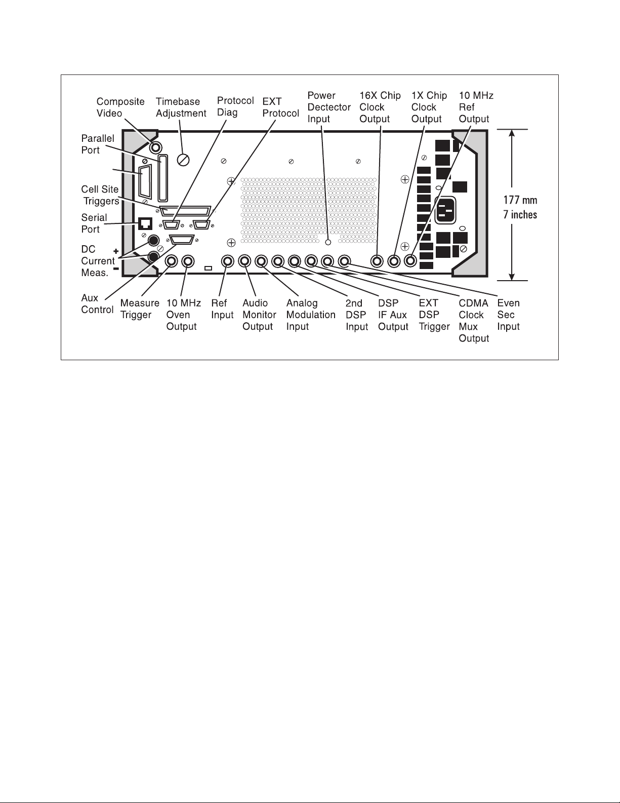
Front Panel
Page 14
14
Front Panel Inputs
RF Input/Output: Type N
Antenna Input: BNC
Microphone/Accessory: 8-pin DIN
Audio Input: Dual BNC’s
Rear Panel Inputs
Modulation Input (analog): BNC
Measurement Trigger [input for oscilloscope]: BNC
Reference Input: BNC
Second DSP Auxillary [Baseband] Input: Not
functional
Even Second Input: BNC
External DSP [Input]: BNC
Power Detector [input for 83236B]: SMA
DC Current Measure [input]: Dual banana jacks
Rear Panel Digital Ports
Aux. Control: 15-pin sub-min D [Open loop power
trigger output]
Parallel Printer Port: Centronics 25-pin sub-min D
Serial Port (RS-232): RJ-11
Ext. Protocol: Not functional
Protocol Diag: Not functional
GPIB Port: 24-pin GPIB
Front Panel Outputs
RF Input/Output: Type N
Duplex Output: BNC
Audio Output: BNC
Rear Panel Outputs
CRT Video Output: BNC
Audio Monitor Output: BNC
10 MHz Oven Output: BNC
10 MHz Reference Output: BNC
CDMA [Frame] Clock Multiplexer Output: BNC
16X Chip [19.6608 MHz Clock] Output: BNC
1X Chip [1.2288 MHz Clock] Output: BNC
DSP IF Aux [3.6864 MHz] Output: BNC
Cellsite/Triggers: 37-pin sub-min D [protocol
logging output]
Rear Panel
GPIB
( )
Page 15

15
Option 001
AMPS/NAMPS/CDMA
CDMA RX/TX Quick General Test
CDMA RX/TX Voice Quality
CDMA Call Processing Registration
CDMA Call Processing Origination
CDMA Call Processing Page
CDMA Call Processing Release
CDMA Call Processing Digital to Analog
Hand-off
CDMA Call Processing Talk Time
CDMA Call Processing Check
CDMA CP Softer Hand-off Add and Drop Check
CDMA RX Sensitivity and Dynamic Range
CDMA RX Traffic Channel FER with AWGN
CDMA RX Sensitivity Level Search
CDMA TX Modulation Quality
(includes frequency accuracy)
CDMA TX Open Loop Power Control Accuracy
CDMA TX Closed Loop Power Control Range
CDMA TX Maximum RF Output Power
CDMA TX Minimum Controlled Output Power
CDMA TX Spectrum Emissions
AMPS/NAMPS CP Call Processing
Registration
AMPS/NAMPS CP Call Processing Page
AMPS/NAMPS CP Call Processing Release
AMPS/NAMPS CP Call Processing Origination
AMPS/NAMPS Call Processing Hook Flash
AMPS/NAMPS CPA Flow Chart
(manual phone test)
AMPS/NAMPS TX Functional Test
(no audio connections)
AMPS/NAMPS TX Frequency Error
AMPS/NAMPS TX RF Output Power
AMPS/NAMPS TX Modulation
Deviation Limiting
AMPS/NAMPS TX Audio Frequency Response
AMPS/NAMPS TX Audio Distortion
AMPS/NAMPS TX Signaling Tone/DST
AMPS/NAMPS TX FM Hum and Noise
AMPS/NAMPS TX SAT/DSAT
AMPS/NAMPS TX RVC Data Deviation
AMPS/NAMPS TX Compressor Response
AMPS/NAMPS TX Current Drain
AMPS/NAMPS TX DTMF Frequency Error
AMPS/NAMPS TX Switch Channels
AMPS/NAMPS TX Quick General Test
AMPS/NAMPS RX Expandor Response
AMPS/NAMPS RX Audio Frequency
Response
AMPS/NAMPS RX Audio Distortion
AMPS/NAMPS RX Hum and Noise
AMPS/NAMPS RX Sensitivity (SINAD)
AMPS/NAMPS RX FVC Order Message
Error Rate
AMPS/NAMPS RX Quick General Test
NAMPS RX MRI Performance
Option 003
JTACS/NTACS/CDMA
CPA Registration
CPA Page
TXA Frequency Error
TXA Carrier Power
TXA Peak Frequency Deviation
TXA Audio Frequency Response
TXA Audio Distortion
TXA Signaling Tone / DST
TXA FM Hum and Noise
TXA SAT / DSAT
TXA RVC Data Deviation
TXA Compressor Response
TXA Current Drain
RXA Expandor
RXA Audio Frequency Response
RXA Audio Distortion
RXA Hum and Noise
RXA SINAD
RXA FVC Order Message Error Rate
CPA Release
CPA Origination
OTA No Audio Functional
TXA Quick General
RXA Quick General
CPA Flow Chart
TXA Switch Channels
CPA Hook Flash
TXA DTMF Frequency Error
CPD Registration
CPD Origination
CPD Page
TXD Waveform Quality and Freq. Acc.
TXD Open Loop Power Range
TXD Closed Loop Power Control
TXD Maximum RF Output Power
TXD Min. Controlled Output Power
RXD Traffic Channel FER
RXD Sensitivity and Dynamic Range
CPD Softer Hand-off
CPD CDMA Voice Quality
TXD Spectrum Emissions
CPD CDMA Release
CPD Digital to Analog Hand-off
CPD Talk Time
RXD Sensitivity Level Search
Option 004
CDMA/PCS/AMPS/NAMPS
CPA Registration
CPA Page
TXA Frequency Error
TXA RF Power Output
TXA Modulation Deviation Limiting
TXA Audio Frequency Response
TXA Audio Distortion
TXA Signaling Tone / DST
TXA FM Hum and Noise
TXA SAT / DSAT
TXA RVC Data Deviation
TXA Compressor Response
TXA Current Drain
RXA Expandor
RXA Audio Frequency Response
RXA Audio Distortion
RXA Hum and Noise
RXA SINAD
RXA FVC Order Message Error Rate
CPA Release
CPA Origination
OTA No Audio Functional
TXA Quick General
RXA Quick General
CPA Flow Chart
TXA Switch Channels
CPA Hook Flash
TXA DTMF Frequency Error
RXA MRI
CPD Registration
CPD Origination
CPD Page
TXD Waveform Quality and Freq. Acc.
TXD Open Loop Power Range
TXD Closed Loop Power Control
TXD Maximum RF Output Power
TXD Minimum Controlled Output Power
RXD Traffic Channel FER
RXD Sensitivity and Dynamic Range
CPD Softer Hand-off
RTD RX/TX CDMA Quick General
CPD CDMA Voice Quality
TXD Spectrum Emissions
CPD CDMA Release
CPD Digital to Analog Hand-off
CPD Talk Time
RXD Sensitivity Level Search
83217A CDMA Dual-Mode Mobile Station Test Software Test List
Page 16

CDMA Tests
CDMA Registration
CDMA Origination
CDMA Page
CDMA Base Station Release
CDMA Quick General
CDMA Waveform Quality and
Frequency Accuracy
CDMA Open Loop Power Range
CDMA Closed Loop Power Control
CDMA Maximum RF Output Power
CDMA Minimum RF Output Power
CDMA Traffic Channel FER with AWGN
CDMA Sensitivity and Dynamic Range
CDMA Softer Hand-off
CDMA Voice Quality
CDMA Spectrum Emissions
CDMA Talk Time
CDMA Sensitivity Level Search
CDMA Digital to Analog Hand-off
Analog Tests
Analog Registration
Analog Page
Analog Origination
Analog Base Station Release
Analog TX Quick General
Analog RX Quick General
Analog No Audio Functional
Analog TX Frequency Error
Analog Tests, continued
Analog TX RF Power Output
Analog TX Modulation Deviation Limiting
Analog TX Audio Frequency Response
Analog TX Audio Distortion
Analog Signaling Tone/DST
Analog TX FM Hum and Noise
Analog SAT/DSAT
Analog RVC Data Deviation
Analog Compressor Response
Analog Current Drain
Analog Expandor Response
Analog RX Audio Frequency Response
Analog RX Audio Distortion
Analog RX Hum and Noise
Analog SINAD
Analog FVC Order Message Error Rate
Analog No Audio Functional
Analog Switch Channels
Analog Hook Flash
Analog DTMF Frequency Error
Analog NAMPS MRI
Other Tests
Change Global Parameters
Change Channel For
Change Channel List
Access to a User DLL
Agilent Technologies’ Test and Measurement
Support, Services, and Assistance
Agilent Technologies aims to maximize
the value you receive, while minimizing
your risk and problems. We strive to
ensure that you get the test and measurement capabilities you paid for and obtain
the support you need. Our extensive support resources and services can help you
choose the right Agilent products for your
applications and apply them successfully.
Every instrument and system we sell has
a global warranty. Support is available
for at least five years beyond the production life of the product. Two concepts
underlie Agilent’s overall support policy:
“Our Promise” and “Your Advantage.”
Our Promise
“Our Promise” means your Agilent test
and measurement equipment will meet its
advertised performance and functionality.
When you are choosing new equipment,
we will help you with product information, including realistic performance specifications and practical recommendations
from experienced test engineers. When
you use Agilent equipment, we can verify
that it works properly, help with product
operation, and provide basic measurement
assistance for the use of specified capabilities, at no extra cost upon request. Many
self-help tools are available.
Your Advantage
“Your Advantage” means that Agilent
offers a wide range of additional expert
test and measurement services, which you
can purchase according to your unique
technical and business needs. Solve problems efficiently and gain a competitive edge
by contracting with us for calibration, extracost upgrades, out-of-warranty repairs, and
on-site education and training, as well
as design, system integration, project management, and other professional services.
Experienced Agilent engineers and technicians worldwide can help you maximize
your productivity, optimize the return on
investment of your Agilent instruments and
systems, and obtain dependable measurement accuracy for the life of those products.
Get assistance with all your
test and measurement needs at:
www.agilent.com/find/assist
Product specifications and descriptions in
this document subject to change without notice.
Copyright © 1997, 2000 Agilent Technologies
Printed in U.S.A. 4/00
5968-4094E
E8290A Point of Service Test (PoST) Software Test List
 Loading...