


Motorola AMPS/NAMPS Cell Site Test Software
HP 11807B Option 040 Software User’s Guide
for the HP 8921A
Software Version B.01.00 and above
HP Part No. 11807-90153
Printed in U. S. A.
May 1997
Rev A
1

Copyright © Hewlett-Packard Company 1995
RESTRICTED
RIGHTS LEGEN D
Use, duplication or disc losu re by the U.S. Gover nment is subj ect to restr ictio ns as
set forth in su bparagr aph ( c) (1) ( ii) of t he Right s in Techni cal Data a nd Computer
Software clause in DFARS 252.227-7013.
Hewlett-Packar dCompany
3000 Hanover Street
Palo Alto, CA 94304
U.S.A.
Rights for non-DOD U.S. Government Departm ents and Agencie s are as set forth
in FAR 52.227-19 (c) (1, 2)
2

Contents
1 Product Description
About the Test Software 24
About the Test System 25
Testable Cell Site Equipment 26
Using the Test Software 27
Firmware Differences 28
To Setup Printer Using HP 8921A FW Below Rev A.14.00 32
Table of Contents
Table of Contents
Getting Started 34
To Turn On and Set Up the Test Set: 35
To Select T est Software Procedure Location: 36
To Select T est Software Procedure Location: (Co ntinued) 37
To Load and Run Tes t Software: 38
To Load and Run Tes t Software: (Continued) 39
To Change the Order of Tests: 40
To Change the Order of Tests: (Continued) 41
To Select URDM or RDM Frequency/Level test: 42
To Select URDM or RDM frequency/level test: (Continued) 43
To run TEST_02 URDM or RDM Fr equency/Level: 44
To run TEST_02 URDM o r RDM Fr equency/Level: (Continued) 45
Learning To Use the Test Software 46
In this Manual 47
Manual Contents 48
Conventions Used 49
3

Contents
2 Equipment
Cell Site Equipment 52
Memory Ca rd s 53
Test Software Memory Cards 54
SRAM Cards 55
Memory Card Storage Space 56
HP 8921A Cell Site Test Set 57
Test Set Firmware 57
Test Set Op tio n 57
Other Software Tools 58
Peripheral Items 59
HP Supplied Peripheral Items 60
61
RF and Audio Switching Arrangements 61
RF and Audio Switches 61
Switch Control Input Buffer 62
RF Couplers 62
50-Ohm Terminations 62
Cables, A dapters, and Connecto rs 63
HP Supplie d Connector Kit 65
VSWR and Cable Fault Ancillary Equipment 65
High Accuracy Frequency Reference 65
Documentation 66
Vendor Information 67
4

Contents
Table of Contents
3 Setting Up
Equipment Connections 70
Receiver RF Connections 74
Transmitt er RF Connections 74
Audi o C on nect ions 7 5
Conne ction for
RS-232 Base Station Control 75
Serial Port Connections for Dat a C ollection 75
Printer Connection 76
Serial Port Location 76
Parallel Port Location 78
Disk Drive Connections 78
Radio Interface Connections 79
DC Power to the RF and Audio Swit ches 80
Determining Calibration Parameters 81
Transmitter Path Loss Calibration 81
Receiver Path Loss Calibration 85
Referen ce D istribution Module Level Correction Factor 88
Combiner to Test Set Path Loss Factor 90
Procedures 91
Saving a Procedure 92
Loading a Procedure 94
Deleting a Procedure 94
Securing a Procedure 95
Un-Securing a Procedure 96
Copying a Procedure 97
Entering Parameters, Pass/Fail Limits, and External Device
Configuration 99
Parameters 99
Pass/Fail Limits (Specifications) 101
External Device Configuration 102
Making Entries in a Test Set Configuration Screen 10 8
Serial Ports 108
5

Contents
Serial Port Configuration 109
HP-IB Port C on f ig ur ation 112
Data Collection 113
Collection to an SRAM Card or Disk 113
Collection to a PC 116
Retrieving Data from an SRA M Card 116
Retrie ving Data from a D isk 118
6

Contents
Table of Contents
4 Running Tests
What are Tests? 120
TESTS 120
TESTs 120
Tests 121
Order of TEST s 121
TESTS (Main Menu) Screen 122
Starting the Program 124
When the Program Starts Running 130
Entering the Order of TESTs 132
TEST Configuration Settings 134
Test Execution Conditi ons 135
If Unit-Under-Test Fails: 135
Test Pr oced ur e Run Mo de: 135
Output Results For: 136
Output Results To: 136
Output Heading: 136
HP-IB Control Annunciators 137
Pausing or Stopping a TEST 138
Continuing a TEST 139
Test Time Summary 140
Saving Test Results 141
7

Contents
5 TESTs - Reference
USER Keys 144
All Cal 144
Clr Scr 144
Continue 144
Del Chan 144
Delet Stp 144
Disp Data 144
Done 144
HDII Loc
LD Loc
NAMPS Loc 144
Insrt Stp 145
Key/Dekey 145
Laptop 145
LNA Offs 145
Next Wind 145
Next Chan 145
Next Ant 146
Page Up
Page Down 146
Prev Ant 146
Prev Chan 146
Print All 146
Prt Full 146
Re-test 146
Run 146
Run Test 147
Send ESC 147
Send FREE 147
Send TM 147
Send USE 147
Show Log 147
Skip Sens
Skip SAT
Next Ant
Skp N SSI 147
Sngl Step 148
8

Contents
Stop Test 148
Take It 148
Tns off
Tns quiet
Tns loud 148
To Chan 148
Yes,
No 148
Zoom 148
-60 dBm
-90 dBm
-100 dBm 148
Table of Contents
TEST_01 - Laptop Emulator 149
Sending Commands 149
Using the
PC/Modem mode 150
Messages 151
Baud Rate 151
Base Station Password 152
Base Station Report 152
Exiting TEST_01 152
TEST_02 - URDM or RDM Frequency/Level 153
Selecting the T est State 153
Calibration Factor 153
Questions Displayed 154
Frequency Error Refers To 154
Tests 154
Pass/Fail Limits 155
Param eters 155
TEST_03 - Voice Transceiver 156
Selecting the T est State 156
AMPS or NAMPS 156
Calibration Parameters 157
Questions Displayed 157
Frequen cy Error 157
Keying the Transmitter 157
Tests 158
9

Contents
Pass/Fail Limits 159
Param eters 161
TEST_04 - Signaling Transceiver MANUAL Mode 163
MANUAL Mode 163
HDII or LD Equipment 164
Calibration Parameters 164
Questions Displayed 164
Tests 167
Pass/Fail Limits 167
Param eters 168
TEST_05 - Scanning Receiver MANUAL Mode 169
MANUAL Mode 169
AMPS or NAMPS 169
Connections 169
Calibration Parameters 169
Questions Displayed 169
Tests 171
Pass/Fail Limits 171
Param eters 172
TEST_06 - Combiner Adjustment 173
Calibration Parameter 173
Running TEST_06 - Com biner Adjustment 174
Questions Displayed 174
Test 174
Pass/Fail Limits 174
Param eters 174
TEST_07 - Wideband Data on an Active Voice Channel 175
Test 176
Pass/Fail Limits 176
Param eters 176
TEST_08 - Manual Switch and Calibratio n Aid 177
Routines 177
Pass/Fail Limits 178
10

Contents
Table of Contents
Parameters 178
TEST_09 - Calculate Transmitter Power 179
Avai la bl e Entri es 179
Pass/Fail Limits 180
Param eters 180
TEST_10 - Voice Channel Manual Test Mode 181
Pass/Fail Limits 182
Param eters 183
TEST_11 - Test Menu 184
Pass/Fail Limits 185
Param eters 185
11

Contents
6 Parameter s - Refer en ce
Parameter Descriptions 189
GN alwa ys cal si g/ scan [0= n o 1=yes] 189
GN auto exit adj [0=no xx=times in spec] 189
GN perform adj [0=n o 1=fail 2 =always] 189
GN perform extended tests [0=no 1=yes] 189
GN site Average Voice Level (AVL) (dBm) 189
GN sit e ha s L N As [0=n o 1 = yes] 190
GN site [0=non-wireline 1=wireline] 190
GN test state of [0=INS_OPT 1=MANUAL] 190
GN type of site [0=omni 1=sec .skip ant] 190
GN verify all select ions [0=no 1=yes] 190
RDM lev e l co rrecti o n fa ctor (dB ) 190
RX level for scanner DSA T detector (dBm) 190
RX level for scanner SAT detector (dBm) 191
RX level for voice DSAT/ D ST detecto r (dBm) 191
RX level fo r voice SAT/ST detector (dBm ) 191
RX path loss to antenna 1 (dB) 191
RX path loss to antenna 2 (dB) 191
RX path loss to antenna 3 (dB) 191
RX path loss to antenna 4 (dB) 191
RX path loss to antenna 5 (dB) 191
RX path loss to antenna 6 (dB) 191
RX/TX audio f req response step [.01-2.7] 191
SC fewer li nearity channels [0=no 1=yes] 192
SC skip items in scan test [0=no 1=yes] 192
TX output power for l evel 0 (Watts) 192
TX output power for l evel 1 (Watts) 192
TX output power for l evel 2 (Watts) 192
TX output power for l evel 3 (Watts) 192
TX output power for l evel 4 (Watts) 192
TX output power for l evel 5 (Watts) 192
TX output power for l evel 6 (Watts) 192
TX output power for l evel 7 (Watts) 192
TX output power for si gnaling unit (Watts) 192
TX path loss to combiner for adjustment (dB) 193
TX path loss to harmonic filter 1 (dB) 193
12

Contents
Table of Contents
TX path loss to harmonic filter 2 (dB) 193
TX path loss to harmonic filter 3 (dB) 193
TX path loss to harmonic filter 4 (dB) 193
TX path loss to harmonic filter 5 (dB) 193
TX path loss to harmonic filter 6 (dB) 193
TX path loss to harmonic filter 7 (dB) 193
TX path loss to harmonic filter 8 (dB) 193
TX perform loopback test [0=no 1=yes] 194
TX steppi ng PA p w r lvls tested [0-127] 194
TX peak voice limit step 194
TX voice/signal pwr use [0=anz 1=pwrmtr] 194
ZZZZ test mode [0=normal 1=demo] 195
13

Contents
7 Pass/Fail Limits (Speci fi cations) - Reference
Pass/Fail Limit (Specification) Descriptions 199
RDM frequency error (Hz) 199
RDM output level (volts peak to peak) 199
RX audio distortion (percent) 199
RX audio output level (dBm) 199
RX audio res ponse dev from -6 dB/ oct R1 (dB) 199
RX audio res ponse dev from -6 dB/ oct R2 (dB) 199
RX expandor track erro r < 0 dB (dB) 199
RX expandor track erro r > 0 dB (dB) 200
RX hum and noise ( dB) 200
RX scan and si g calibrati on reading (dBm ) 200
RX scan sig li nearity error (dB) 200
RX sensitivity with LNA (dBm) 200
RX sensitivity without LN A (dBm ) 200
RX sensitivity without LN A narrow mode (dBm) 200
RX SINAD at sensitivity spec (dB) 200
TX audio dist ortion (p ercent ) 20 0
TX audio res ponse dev fr om 6 dB /oct (dB) 201
TX compre ssor track error <0 dB (dB ) 201
TX compre ssor track error >0 dB (dB ) 201
TX data deviation (kHz) 201
TX DSAT deviation (Hz) 201
TX FM hum and nois e (dB) 201
TX frequency error (ppm) 201
TX loopback level (dBm) 201
TX output power error at level 0 (percent) 201
TX output power error at level 1 (percent) 202
TX output power error at level 2 (percent) 202
TX output power error at level 3 (percent) 202
TX output power error at level 4 (percent) 202
TX output power error at level 5 (percent) 202
TX output power error at level 6 (percent) 202
TX output power error at level 7 (percent) 202
TX output power erro r for signa ling unit (percent) 202
TX SAT deviation (kHz) 202
TX SAT frequency error (Hz) 202
14

Contents
Table of Contents
TX test point JK output (dBm) 203
TX voice deviation (kHz) 203
TX voice deviation nar row mode (kH z) 203
TX voice limiting deviation (kHz) 203
TX voice limiting deviation narrow mode (kHz) 203
15

Contents
8 Problem Solving
Base Station Control Difficulties 207
Data-Collection Function Does Not Work 208
Exiting the Program 210
Equipment Control 212
Memory Space Problems 213
Printing Problems 214
Test Results are Unexpecte d 215
Test Set Doesn’t Power Up 216
Unstable SINAD Readings 217
16

Contents
Table of Contents
A Appendix: Using the HP 3488A Switch/Control Unit 219
17

Contents
B Appendix: Test Set Measurement Settings 223
224
TEST_02 - URDM or RDM Frequency/Level 224
TEST_03 - Voice Transceiver 225
TEST_04 - Signaling Transceiver MANUAL Mode 229
TEST_05 - Scanning Receiver MANUAL Mode 230
TEST_06 - Combiner Adjustment 230
TEST_07 - Wideband Data on Active Voice Channel 230
TEST_08 -Manual Switch and Calibration Aid 230
TEST_09 - Calculate Transmitter Power 231
TEST_10 - Voice Channel Manual Test Mode 231
18

Contents
and Printer 233
Table of Contents
C Appendix: Cable Wiring Diagrams for Data Collection to PC
19

Contents
Glossary 235
20

Contents
Table of Contents
Index 239
21

Contents
22

1
Product Description
Chapter 1
Product Description
23

Chapter 1, Product Description
About the Test Software
About the Test Software
The HP 11807B Option 040 Motorola AMPS/NAMPS Cell Site Test Software is
used with the HP 8921A Cell Site Test Set, and various ancil lary equipment, to
test the functionality of Motorola cellular telephone base stations. The Test
Software package, as shippe d, co ntains the following items:
• HP 11807B Option 040 Cell Sit e Tes t So ftware Card, part number HP 11807- 10012
• HP 11807B Option 040 Test Software User’s Guide, part number HP 11807-90153
• Software licensing agreement, part num ber 5180-1566
• 128-kilobyte Memory (SR AM) Card (part num ber HP 85702A) for st oring customiz ed
tes t pr o gram s and resu lts.
• Cable and adap tor for serial connection to the base station
• 6-Conductor RJ11 (m) — RJ11 (m) cable, part number 08921-61015
• RJ11 (f) — DB25 (m) adaptor, part number 08921-61016
The following features of the Test Softwa re simplify testing:
• The Test Software sends base station control comma nds automaticall y fr om th e Tes t
Set via the RS-232 interface . The Test Softwa re also displays responses from the base
station.
• The Test Software displays the location of an adjustment whenever adjustment is
required.
• The Test Software displays a large meter on the Test Set screen and provides variabl e
auditory feedback while adjustments are being made.
• The Test Software displays system interconnects on the Test Set screen whenever cable
connections mus t change.
• The Test Software displays results of test s and pas s/fail indicat ions on the Test Set
screen, and supplies the results and indications for printing or collecting in an HP
Palmtop comp u t er, a P C , a di s k driv e , or a memory (S R A M ) ca r d .
• The Test Softwar e co n trols switche s that se lect the external RF or audio signal paths.
• The Test Software allows you to cha nge the order of TESTs, pass/fail limits,
parameters, and extern al device configurations.
• The Test Software provi des that bas e stat ion control command s can be sel ecti vely sen t
as the tests proceed.
• The Test Software pr ovides t ha t RF pa th losse s ca n be det ermined and a ccommod ated.
24

About the Test System
Chapter 1, Product Description
About the Test Sy stem
When the Test Software is used with the HP 8921 A Test Set and the various other
equipment, the combined system is called the Test System. The following items
make up the Test System:
• HP 11807B Option 040 Motorola AMPS/NAMPS Cell Site Test Software.
• HP 8921A Cell Site Test Set.
• Accessories:
• HP 83202A Option 040 Base Station Accessory Kit.
or
• Other switch and in terconn ect arrangements.
In addition, it would be helpful to have available the RF Tools in the HP
11807A,E Option 100 System Support Tests software package. The Option 100
software package offers a range of tests that may be used as adjuncts to those in
the Test Software.
Note that the following thre e tests that were in previous versions of the Test
Software w ere rem o ved fo r this version (B.01.00):
• VSWR Swept Return Loss.
• VSWR Discret e Channel Return Loss.
• VS W R vs D ist an ce (cabl e f au l t)
Product Description
Chapter 1
These tests are now included the RF Tools section of Option 100 software
package.
This system performs tests that determine the quality of the RF and audio
performance of several types of Motorola AMPS and AMPS/NAMPS cellular
base stations. Most of the measuremen t methods and specific ations use d for these
tests are derived from Electronic Industri es Association st andards and procedures
recommended by Motorola.
25

Chapter 1, Product Description
Testable C el l Site Eq uipment
Testable Cell Site Equipment
The Test System allows you to test Motorola HDII, HDII/NAMPS, and LD Base
Stations. The firmware revision of the bas e station to be tested must be 4.3.2.1 or
higher.
Specific equipment that you can te st includes voice transceivers, scan receivers,
signaling transc eivers, combiners, power amplifiers, and universal refere nc e
distribution modul es. The Test Software includes major adjustment procedures.
26

Using the Test Software
Chapter 1, Product Description
Using the Test Software
IMPORTANT
CAUTION:
This Test Software can be used during routine cell site verification and after the
installation or repair of cell site equipment. Base stations can be tested while in
the In-Service Optimiz at ion Mode or in the Manual Mode. The Manual Mode
must be used for some of the TESTs. There are instances in which it may be
advantageous to choose one of these modes over the other.
Before you connect the Test Set to a base station, you should underst and the potential
results of your act ions. Dropped calls, accidental modification of base stati on calibration
data, and other undesirable effects can occur.
The next two sections will get you started learning to use the Test Software. The
first of the two, “Getting Started”, contains steps to follow if you have not run
Test Software on a Test Set. The second of the two, “Learning to Use the Test
Software”, describes steps that you should follow in continuing to learn to use the
Test Software.
Product Description
Chapter 1
27

Chapter 1, Product Description
Firmware D ifferences
Firmware Differences
Firmware revision A.14.00 in the HP 8921A,D Cell Site Test Set introduced
several enha ncements to the TESTS menus. Wit h th e enhance ments were cha nges
to the menu structure used in the TESTS (Main Menu) screen and its sub-screens.
This manual is written for instruments with firmware revision A.14.00 and
higher. To assist users with instruments with older firmware, this section
summarizes the change s and shows the corr espondenc e between revis ion A.14 .00
screens and those of the earlier versions.
28

Chapter 1, Product Description
Firmw are D if fer ences
NOTE: If you are unsure of the firmware revision of your unit, press and release the SHIFT key
then press the DUPLEX key. A configuration screen will be displayed and the firmware
revision is sho wn in the upper right of the screen. Contact Hewlett-Packard at
1-800-922-8920 for details on upgrading your instrument if desired.
Product Description
Chapter 1
29

Chapter 1, Product Description
Firmware D ifferences
Using the TESTS
Menu Comparison
NOTE: The information in * and ** are for use rs of Test Sets with firmware revisions below
A.14.00. Please dis regard this materia l if your Test Set has a firmware revi sion of A.14.00
or higher.
The next two figur es show the TESTS (Main Menu) sc reens for the latest TESTS
menu (figure 1 ) and the TESTS menu used in older firmware revisions
(figure 2 ). The illustrations are intended to help you find the corresponding
functions if you are working with older firmware revisions.
To use the comparison, follow these steps:
1. When you enc ounter a procedure or diagram referring to a TESTS (Main Menu) field
selection or name that d oes n ot appe ar on your T ESTS (Ma in Menu) (or ma y a ppear i n
a different location on the display), refer back to these figures.
2. Loo k for t he sel ection desc ript ion or na me in figure 1 and no te the corres ponding l etter .
3. Look for the same letter in figure 2 and note whic h field (or sub-menu) is used in the
older firmware to access the screen or field.
4. Once in the sub- menus, the old a nd new scree ns are very similar a nd you shoul d be able
to use the docu me ntation as-is.
G
F
A
B
C1
C2
C3
C4
C5
Figure 1 TESTS Main Menu for Firmware Revisions of A.14.00 and greater.
30
D
C6
E
C7

Chapter 1, Product Description
Firmw are D if fer ences
Product Description
B
A
D
E*
C**
*See "To Setup Printer Using HP
8921A FW Below Rev A.14.00" on
page 32
Chapter 1
G
F
C3
C1
C4
C2
C6
C5
C7
**Selecting Test Fu nctions
opens the Choices menu.
Figure 2 TESTS Main Menu for Firmware Revision Below A.14.00
31

Chapter 1, Product Description
Firmware D ifferences
To Setup Printer Using HP 8921A FW Below Rev A.14.00
1. Press the TESTS key.
2. Select Edit Cnfg from the Test Function field.
3. Po sition the cursor to the Inst# field and select it.
4. Rotate the knob until an empty Calling Name field appears, and select it.
5. Po sition the curs or to the Callin g Name field and select it.
6. Using the list of characters in the Choices menu , en t er th e w o r d PRI N TER .
Select Done when co mplete.
7. Po sition the cursor to the Addr (address) field and select it.
8. Using th e DATA keypa d, ente r 9 for serial printers, 15 for parallel printers, or 70X for
HP-IB prin ters, then pr ess ENTER.
9. Po sition the cursor to the Options field (directly under Calling Name) and select it.
10. Using the list of characters from the Choices menu, the following command s may be
entered. Separate the commands with commas (example; LN=60,START,END)
• LN equals the number of printed lines per page.
• START causes a form feed at the st art of each p r intout.
• END causes a fo rm feed at the end of each printout.
11. From the To Screen menu, select More.
12. From the Choices menu, select IO CONFIG.
13. For Serial Printers:
• Set the Serial Baud field and other serial communications fields listed under it to
correspond to your printer’s configurati on.
14. For HP-IB Printers:
• Position the cursor to the Mode field and select it.
•From the Choices menu, select Control.
• Position the cursor to the Print Adrs field and select it.
• Rotate the knob and select the HP-IB address of your printer.
• Position the cursor to the Print To field. Pressing the knob will toggle the
underlined selection. Selec t to underline HP-IB.
15. Press the TESTS key to return to the TESTS screen.
32

Chapter 1, Product Description
Firmw are D if fer ences
To print test results
1. Make sure that your printer is pr operly connected and configured as explained ea rlier
in this section.
2. Press the TESTS key.
Product Description
3. Po siti on t he curs or to the Output Results To: field (or the Output Destination field).
Pressing the knob will toggle the underlined selection. Select to unde rline Printer.
4. Po sition the cursor to the Ou tput Heading field and select it.
5. Using the list of characters in the Choices menu, enter a printout heading (optional).
Select Done when the heading is complete.
Chapter 1
33

Chapter 1, Product Description
Getting Started
Getting Started
If you have not run Test Software on a Test Set, follow the procedur e s shown in
the following 11 illustrations to get started.
To perform this procedure, you will use an HP 8921A Cell Site Test Set and the
HP 11807B Option 040 Test Software Card. If you wish to perfor m the steps with
a base station connected, you will r equire the RJ-11 cable and RJ-11/DB25
adaptor to connect the base sta tion RS- 232 connector to the Test Set.
The procedure will guide you in running “TEST_01 - Laptop Emulator”, then in
stopping TEST_01, and then in selecting and running another TEST.
Specifically, the procedure will guide you to:
• Turn-on and set up the Test Set.
• Insert a Test Software card.
• Load and run TEST_01 - Laptop Emulator.
• Stop TEST_01.
• Select and run another TEST.
If you wish to perform these steps with a base station connected, you must
connect the Test S et RJ-11 Seri al B por t to the TTYMP #8 CSC Network Addre ss
Connection. Do this before starting the steps. Se e "Connection for RS-232 Base
Station Control," in chapter 3, on page 75.
For a description of TEST_01, see "TEST_01 - Laptop Emulator" on page 149.
When you have complet ed these steps and feel that you understand the operation,
continue with the next secti on, “Learning to Use the Test Software”.
34
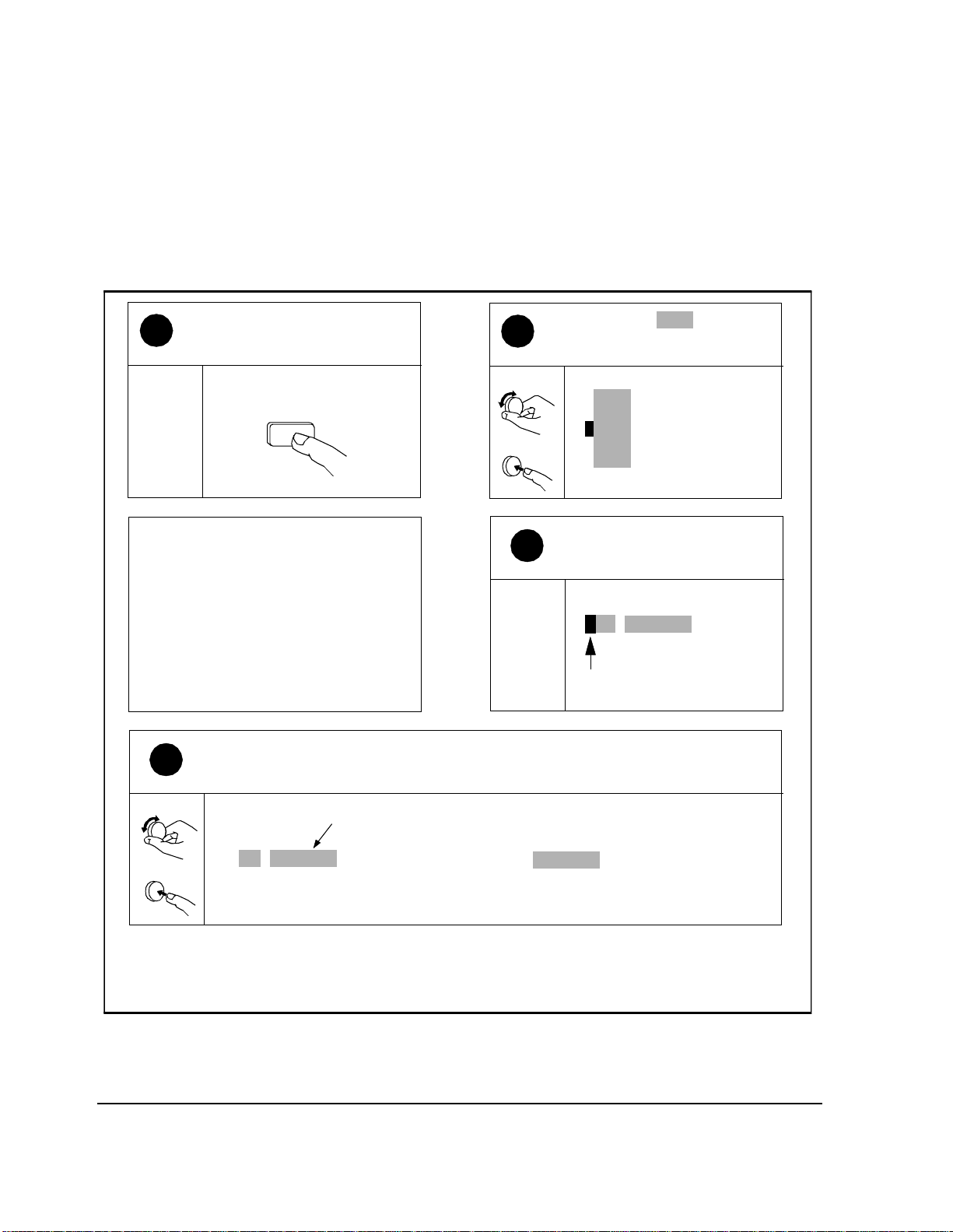
To Turn On and Set Up the Test Set:
Chapter 1, Product Description
Getting St ar ted
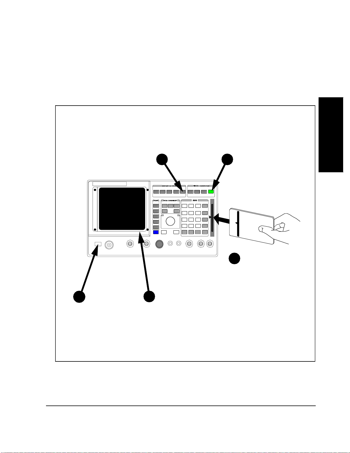
Do steps 1-5 in numbered order.
5
Press TESTS Press PRESET
CURSOR CONTROL
PUSH TO SELECT
4
(PRESET is a reset
command that can be used
at any time to start from the
beginning.)
Insert Card
3
HP 11807B Opt 040
Product Description
Chapter 1
Press POWER
1
Wait about 20 secon ds for
2
a display to appear, th en
go to step 3.
Turn page to list procedures on the memory card
35
Chapter 1, Product Description
Getting Started
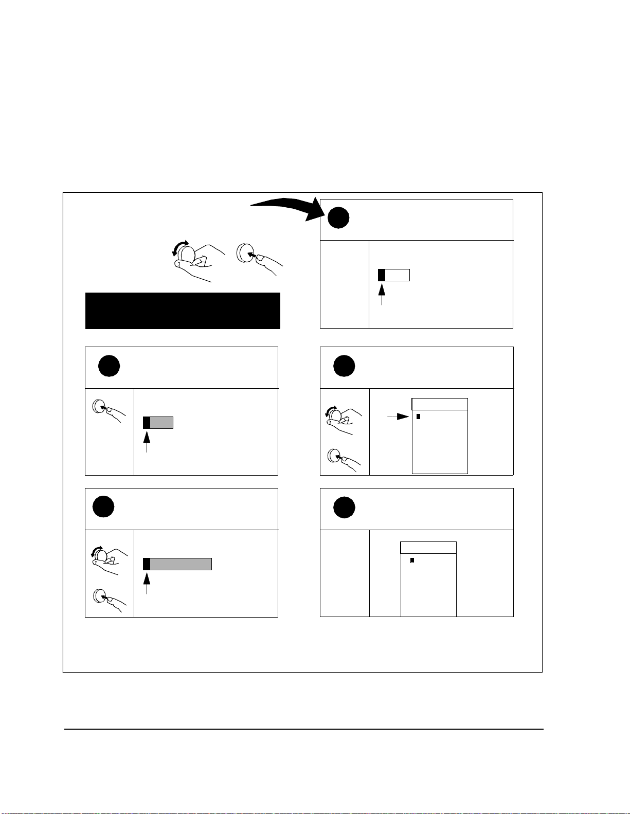
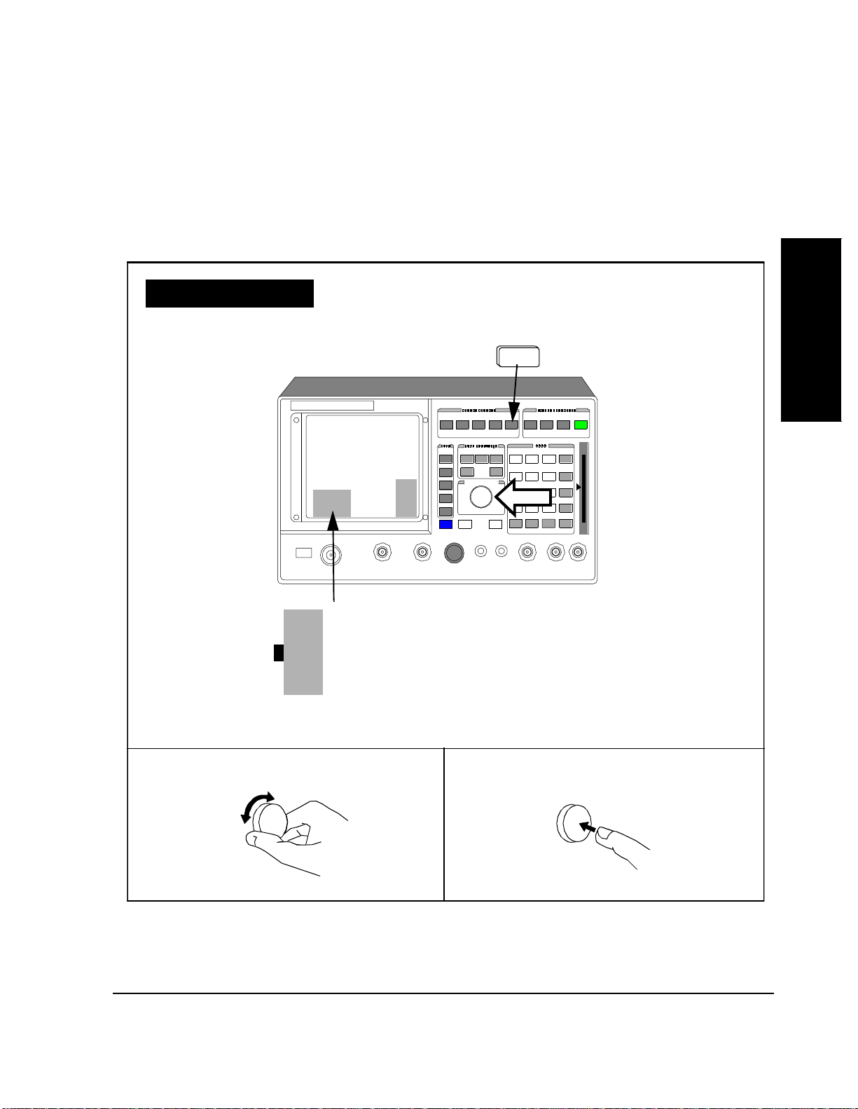
To Select Test Software Procedure Location:
Follow Numbered Steps
Use the cursor control
knob on the front panel
to position the cursor
and make selections.
Use figure on opposite page for
reference.
Press the knob to select
2
Select Procedure Location.
Select
Select Procedure Location:
Position cursor at
4
Select Procedure Filename: and
select it.
Position
Select Procedure Filename:
Position Select
Note; cursor is positioned at
1
Select Pr oc ed u re Locatio n.
Select Procedure Locati on:
If previo us entries
appear disregard them.
Position the cursor at Ca rd and
3
select it.
Position
Select
The Choices: menu s h ould
5
now appear as shown.
Choices:
Card
ROM
RAM
Disk
Choices:
MOT_CS
Select
Turn page to load software
36
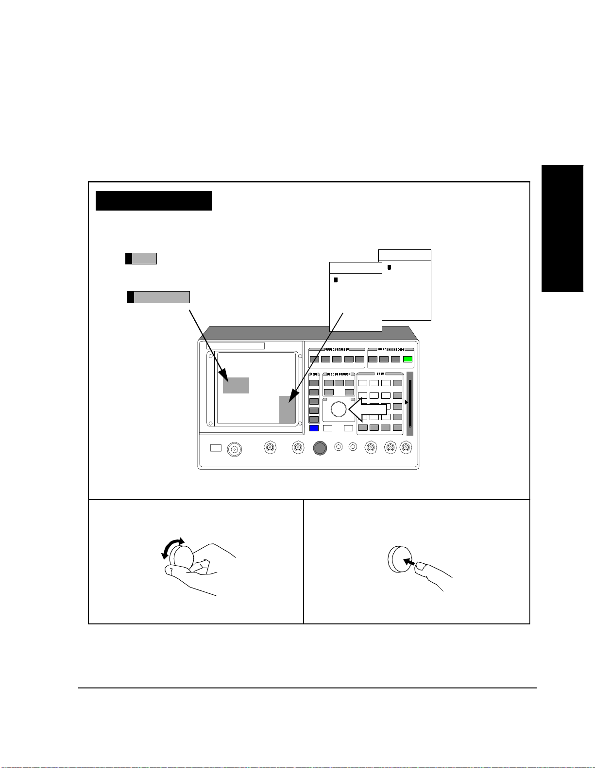
Reference Page
Select Procedure Location:
Select Procedure Filename:
Chapter 1, Product Description
Getting St ar ted
To Select Test Software Procedure Location: (Continued)
Choices:
MOT_CSChoices:
Card
ROM
RAM
Disk
Product Description
Chapter 1
CURSOR CONTROL
PUSH TO SELECT
Knob
Rotate knob to position cursor. Press knob to select a fiel d.
37
Chapter 1, Product Description
Getting Started
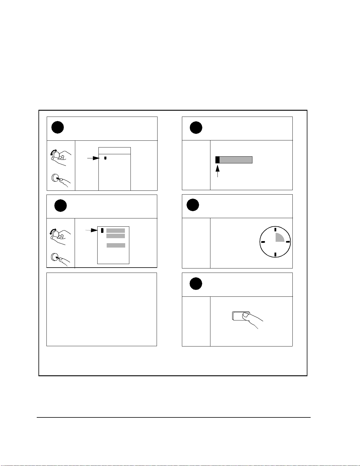
To Load and Run Test Software:
Position cursor at MOT_CS
1
and selec t it.
Position
Select
Position cursor at Run Test
3
and select it.
Position
Select
After MOT_CS is loaded, TEST_1 - Laptop Emulator
begins running.
If the base station is connected, you should see
characters on your display in the box label ed “Base
Station Re s ponse”. See"Serial Port Connections for
Data Collection" on page 75, and "TEST_01 - Laptop
Emulator" on page 149.
Choices:
1
2
4
MOT_CS
Run Test
Continue
Help
Note ; M O T _ C S is no w th e
2
selected proc ed ure filename.
Select Procedure Filenam e:
MOT_CS
The MOT_CS program is loading.
4
Loading program first
time: 2 min. 30 sec.
After first time : 20
sec.
Press <CANCEL> to stop the
5
program.
CANCEL
If the bas e stat ion i s not connec te d, or if y ou wan t to e xit
this TEST and run a new TEST, continue to step 5.
Turn page to select a new TEST
38

Chapter 1, Product Description
To Load and Run Test Software: (Continued)
Getting St ar ted
Product Description
Reference Page
Select Procedure Location:
Card
Select Procedure Filename :
MOT_CS
1
2
4
Run Test
Continue
Help
CURSOR CONTROL
PUSH TO SELECT
Chapter 1
Choices:
MOT_CS
Knob
CANCEL
Rotate knob to position cursor. Press knob to select a field.
39
Chapter 1, Product Description
Getting Started
To Change the Order of Tests:
Press TESTS to display the
1
TESTS (Main Menu) scre e n.
If you are in IBASIC, press SHIFT,
CANCEL before pressing TESTS.
TEST
The Order of Te sts sc reen i s now
present on your CRT.
Use the Order of Tests screen to edit the TEST seque nce, sele ct a new TEST, or delete a
4
TEST.
Position cursor at Seqn Order of
2
Tests and select it.
Position
Channel Information
Freq
Parm
Test Parameters
Order of Tests
Seqn
Pass Fail Limits
Select
3
Spec
Proc
Save/Delete Pr ocedure
Note; cursor is located in the
Step # field.
Example
TEST_02
1
URDM or RDM frequency
Position
Select
TEST_02
1
URDM or RDM frequ ency/level
Test shown is an example, actual test name may be different.
Yes/No
Turn page to select a TEST
40
To Change the Order of Tests: (Continued)
Chapter 1, Product Description
Getting St ar ted
Product Description
Reference Page
Freq
Parm
Seqn
Spec
Proc
Chapter 1
TESTS
CURSOR CONTROL
Knob
PUSH TO SELECT
Channel Information
Test Parameters
Order of Tests
Pass Fail Limits
Save/D e l et e P r oc ed u r e
Rotate knob to position cursor.
41
Press knob to select a fie ld.

Chapter 1, Product Description
Getting Started
To Select URDM or RDM Frequency/Level test:
Note; cursor is located in the
1
Step # field.
TEST shown is an example only,
actual test may be different.
1 TEST_01
Laptop Emulator
Position curs or at TEST_02 and
3
select it.
Position
Choices:
TEST_01
TEST_02
TEST_03
Select
TEST_04
TEST_05
TEST_06
TEST_07
Position cursor at TEST_01 an d
2
select it.
Position
TEST_01
1
Laptop Emulator
Select
Note; TEST_02 is now ent e r e d.
4
TEST_02
1
URDM or RDM frequency/level
TEST_02 URDM or RDM frequency/
level is now selecte d and ready to run.
To run TEST_02, turn page
42

Chapter 1, Product Description
Getting St ar ted
To Select URDM or RDM frequency/level test: (Continued)
Product Description
Reference Page
1
TEST 02
Choices:
CURSOR CONTROL
PUSH TO SELECT
TEST_01
TEST_02
TEST_03
TEST_04
TEST_05
Chapter 1
Knob
Rotate knob to position cursor.
43
Pres s knob to s elect a f ield.

Chapter 1, Product Description
Getting Started
To run TEST_02 URDM or RDM Frequency/Level:
Press TESTS to display the
1
TESTS (Main Menu) scre e n.
If you are in IBASIC, press SHIFT,
CANCEL before pressing TESTS.
TESTS
The TEST is loading.
3
Wait 20 seconds.
Press <Shift> <CANCEL> to
4
stop the program.
Position cursor at Run Test
2
and select it.
Position
Run Test
1
Continue
2
Help
Select
4
TEST_02 begins running.
If the Test Set is connected to the base
station, see TEST_02 - URDM or RDM
frequency/level in chapter 5.
If the Test Set is not connected, the
program will stop aut omat icall y when it is
unable to continue.
SHIFT
CANCEL
44

To run TEST_02 URDM or RDM Frequency/Level: (Continued)
Reference Page
Run Test
1
2
Continue
Chapter 1, Product Description
USER
Use User keys k1-k5 as
k1
an alternate method
for making selections.
k2
k3
Getting St ar ted
Product Description
Chapter 1
4
Rotate knob to position cursor.
Help
k4
k5
CURSOR CONTROL
PUSH T O SELE CT
TESTS
Knob
Pres s knob to s elect a f ield.
45

Chapter 1, Product Description
Learning To U se the Test Software
Learning To Use the Test Software
To learn to use the
Test Software:
1. Become famil iar with the steps in “Getting Started”
2. Become familiar with the following terms:
• Memory Card and SRAM Card - See "Memory Cards," in chapter 2, on page 53.
• TESTS (Main Menu) Screen - See See "What are Tests?," in chapter 4, on page
120 and see "TESTS (Main Menu) Screen," in chapter 4, on page 122.
• Procedures - See "Procedures," in chapter 3, on page 91.
• TEST_01 through TEST_11 - See chapte r 5, "TESTs - Ref er ence," on page 143.
• Order of Tests - See "Entering the Order of TESTs ," in chapter 4, on page 132 .
• Parameters - See chapter 6, "Parameters - Reference," on page 187.
• Pass/Fail Limits (Specifications) - See chapt er 7, "Pass/Fail Limi ts (Specificat ions)
- Reference," on pag e 197.
3. Bec ome familiar with the tests availa ble in the HP 11807A,E Option 100 System
Support Tests software pack age (commonly referred to as RF Tools).
4. If necessary, calibrate system components, and produce one or more Procedures with
your parameters. See "Dete rmini ng Ca libra tion P aramet ers," in chapte r 3, on p age 81
and See "Procedures," in chapter 3, on page 91.
5. Make the required connecti ons to the base station. See "Equipment Connect ions," in
chapter 3, on page 70.
6. Then, begin performing tests. See chapter 4, "Running Tests," on page 119.
7. If you need detailed information as you are running tests, see chapter 5, "TESTs -
Reference," on page 143, for descriptions of the TESTs.
46

In this Manual
Chapter 1, Product Description
In this Manual
This manual describes the setup and use of the Test Set when running the HP
11807B Option 040 Motorola AMPS/NAMPS Cell Site Test Software. Te st Set
features not descri bed in thi s manual are documented in the HP 8921A User’s
Guide (HP part number 08921-90022).
The chapters in this manual are arranged to help you to ref er to specific
information for the task that you are performing.
Product Description
Chapter 1
47

Chapter 1, Product Description
In this Manual
Manual Contents
Chapter 1 - -Product Description describe s the Test Softwa re and helps you to
get started with the Tes t Soft w are pack a g e.
Chapter 2 - Equipment describes the items that you either will require, or might
require, before you can begin testing. Some of the items might be installed
permanently at the cell site . Skip this chapter if you are certain that necessary
items are present and insta lle d correctly.
Chapter 3 - Setting Up desc ribes installing and connecti ng equipment,
determining calibration factors, and entering parameters, pass/fail limits, and
external device configur ation. The chapter also describes Procedures and data
collection. If tests have been performe d previously at the cell site, you might be
able to refer to figure 3 on page 71 to verify connections, and then skip the rest of
this chapter.
Chapter 4 - Running Tests de scribes selecting a TEST to put into a procedure,
and starting the program.
Chapter 5 - TESTs - Reference describes important aspects of each TEST
available in the Test Software.
Chapter 6 - Paramet ers - Ref erence des cribes a ll para meters av ailab le in the Te st
Software.
Chapter 7 - Pass/Fail Limits (Specifications) - Reference describes all pass/fail
limits available in the Test Software.
Chapter 8 - Problem Solving describes some of the problems that might be
encountered in using the Test Softwa re and Test Set.
Appendix A - Using the HP 3488A Switch/Control Unit describes vari ous
connection factors in use of the Switch/Control Unit.
Appendix B - Test Set Measurement Settings lists the more important Test Set
settings used in manual testing.
Appendix C - Cable Wiring Diagrams for Data Col lection to PC and Printer
includes information required to construct PC and printer interface cables.
The Glossary describes terms that are used in cell site and test descriptions.
48

Chapter 1, Product Description
In this Manual
Conventions Used
Special presentations of text in this manual reflect the appearance of the item
being referenced.
Examples of these special presentations are:
TESTS
A key on the Test Set.
Product Description
Chapter 1
Procedure
USER (Run Test)
0.00000
Characters dis played on the Test Set display.
A USER key in the k ey column next to the Te st Set dis-
play. Run Test appears on the display.
A field on the Test Set display in which entries may be
made.
Titles of documentation are printed in italics.
The term Test Set refers to the HP 8921A.
In the steps in this manual the following words are used to describe cursor and
entry actions:
• select means to rotate the cursor control knob to position the cursor in front of a field
(inverse video area), and then press the knob.
• enter means to use the numeric keypad and the ENTER key or measurement unit s
keys to make entrie s to fi elds. In some p rocedures, enter is used to descr ibe the action
of entering characters into a field.
49

Chapter 1, Product Description
In this Manual
50

2
Equipment
This chapter describes items that you might require before you begin testing.
Some items might become permanent test accessories, installed at the cell site.
Equipment
Chapter 2
51

Chapter 2, Equipment
Cell Site Equipment
Cell Site Equipme nt
A Motorola HDII, HDII/NAMPS, NAMPS-II, or LD Cellular Base Station is
required. Equipment to be tested must be located at an active cell site. All
firmware and downl oadabl e softwa re must be ins ta lled. The base st ation firmware
revision must be 4.3.2.1 or later. Also, a powered-up base station cont roller and
cell site controlle r are required.
52

Memory Cards
Chapter 2 , E quipment
Memory Cards
Memory cards are PC cards that are used for data storage. These cards are
approximately the same length and width as credit cards, but somewhat thicker,
and contain integrat ed cir cuit storage devices.
There are two overall type s of memory cards: Epson card and PCMCIA card. The
principal difference between the cards is the interface connector. The Epson card
is designed to meet Epson Corporation spe cifications. The PCMCIA card is
designed to meet Personal Compute r Memory Card Inter national Associati on
specifications. Both are called PC cards.
For each overall type, there are two sub-types: one-time programmable (OTP),
and static random-access memory (SRAM). Once programmed, OTP cards are
read-only devices. SRAM cards are random-access devi ces from which data may
be read and to which data may be written multiple times.
In the Test System, memory cards are used to store the following:
Equipment
Chapter 2
• HP 11807B Option 040 Test Softwa re co de
• An HP-supplied Procedure, containing:
• A default testing order
• Default parameter values
• Default pass/fail limits
• A Library file
• Procedures that you produce, and that are optim ized for your application
• Data collect ion files
An Epson OTP card serves as the local source medium for the Test Software.
When the OTP card is inserted into the slot on the Test Set front panel, the card
receives power from the Test Set, and the Test Set, upon operator command,
loads the Test Software int o the Test Set memory. Arrows printe d on the card and
Test Set front panel indicate the card direction and orientati on for insertion.
SRAM cards are available for use in storing application oriented Proc edu res and
other application inf ormation.
53

Chapter 2, Equipment
Memory Cards
Test Software Memory Cards
The HP 11807B Option 040 Motorola AMPS/NAMPS Cell Site Test Software is
ordinarily supplie d on an Epson OTP card (HP part number 11807- 10012).
However, the version that you receive might be supplied on an SRAM card.
Determin e the di ffer en ce b etw ee n the two types by looking for a write-protect
switch on the top edge of the car d. If there is a switch, the card is an SRAM card.
If not, it is an OTP card.
CAUTION If your Test Software is resident on an SRAM card, it is possible to delete it accidentally
from the card. To prevent the loss of your program, check the write protect switch on the
SRAM card an d ve rify tha t t he ca rd i s writ e p rote cted. Lea ve the swit ch se t t owar d th e ou tside of the card except while you are writing to it.
The Test Software OTP card may be removed after the program is loaded into the
Test Set memory. The program will remain in memory after a power-down/
power-up cy cle.
54
Chapter 2 , E quipment
Memory Cards
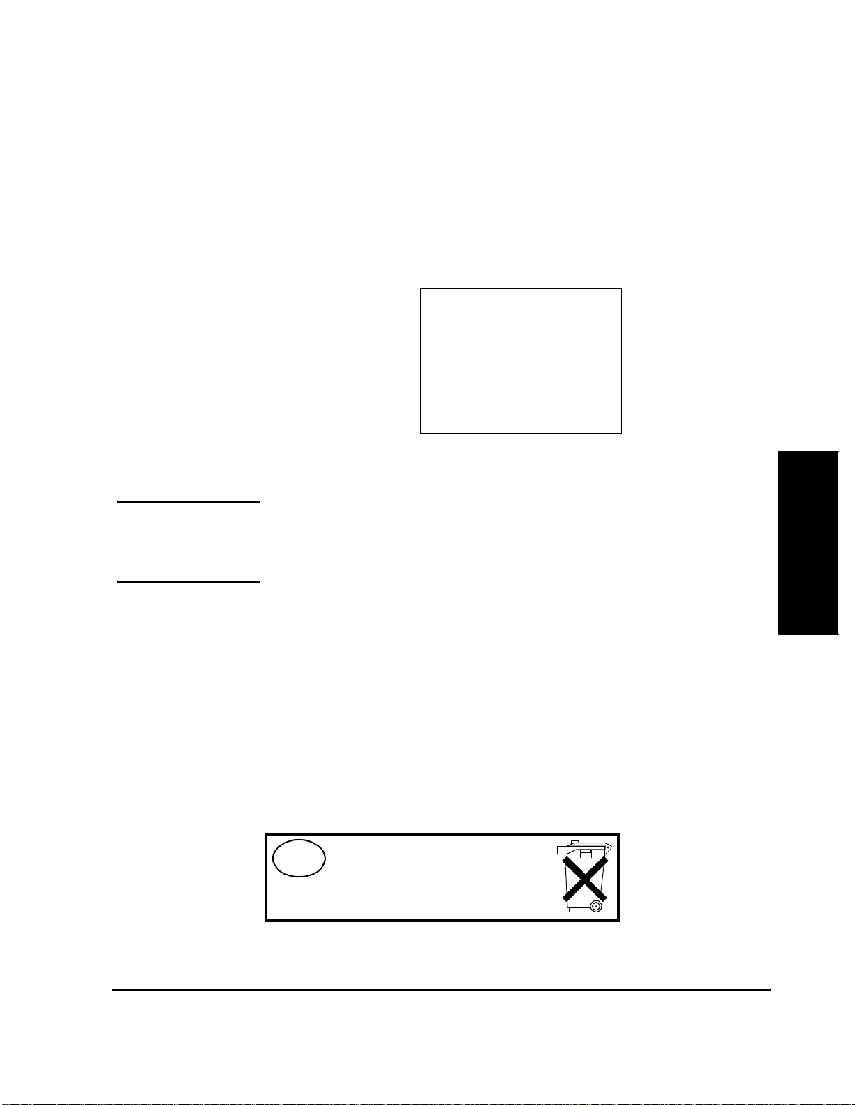
SRAM Cards An SRAM card may be used to store test res ults and Pro cedure s that you produc e.
The SRAM cards listed in table 1 may be used.
Table 1 SRAM Card Part Numbers
Capacity Part Number
32 kilobytes HP 85700A
128 kilobytes HP 85702A
256 kilobytes HP 85704A
512 kilobytes HP 85705A
The SRAM card must be initialized before its fir st use. See "Initiali zing an SRAM
Card," in chapter 3, on page 115.
NOTE: SRAM cards use a battery to retain data while the card is not inserted into a powered-up
Test Set. The lif e o f the b a t te r y dep ends on th e ca r d cap ac i ty an d th e av erage te mp erature
of its environment . S ee the next paragraph.
Each SRAM card uses a li thium batte ry (p art number CR 20 16 or HP par t number
1420-0383). Programs and data will be retaine d for more than one y ear if the card
is stored at 25 degrees Celsius. The card is powered by the Test Set while it is
inserted. When it be comes ne cessary to r eplace th e batt ery, do so while t he card is
inserted into a powered-up Test Set. To retain data and procedures, the battery
should be replaced annually. If you store SRAM cards in a warm environment,
replace the battery more often.
A procedure to replace the battery is described in the HP 8921A User’s Guide.
The write protec t switch on a S RAM card will write-protect the card when it is se t
toward the outside of the card.
NL
Batterij niet
weggooien, maar
inleveren als KCA.
Equipment
Chapter 2
55

Chapter 2, Equipment
Memory Cards
Memory Card Storage Space
Regarding storage space , the following characteristics apply:
• A record is 256 bytes.
• A procedure uses 12 to 16 records.
• A library typically uses 20 to 35 records.
• Only one library is permitted on a card.
• Overhead of approximately 11 kilobytes is required on each card.
Use the following formula to estimate the required storage space:
Storag e Space(in kiloby te s) = (Numbe r of Proced ur es × 4.1) + 17
For example, if you ar e testing ten c ell si tes a nd th e procedur e is di ffer ent for each
site, you will use ten procedures, and 58 kilobytes of memory. Thus, the 128kilobyte card is sufficient.
The storage s pace that you will require for data collection depends on the number
of test res ults to be saved. You will require approximately 4 kilobytes per page of
test results that you save. A page of test results is approximately 57 lines of CRT
or printer output. See "Data Collection" on page 113 for a discussion of memory
card storage space and file types.
In applications in which large quan tities of data will be collected, the sto rage
capacity of smaller SRAM cards is reached quickly. In such instances, data
collection using a PC or printer might be advis able.
56

Chapter 2 , E quipment
HP 8921A Cell Site Test Set
HP 8921A Cell Site Test Set
The HP 11807B Opt 040 Test Software r uns on the HP 8921A Cell Site Test Set.
In this manual, the term Test Set refers to the HP 8921A.
The HP 8921A Cell Site Test Set is an optimized collection of instrument
hardware and firmware, designed to test cellular base stations extensively. Most
of the required hardware and all of the fir mware to tes t cellular base stations has
been included in the standard instrument. Several options may be added,
depending on your applicati on.
Test Set Firmware The HP 8921A firmware revision number must be A.06.09 or later. At the time
this manual was revised, firmware revision A.16.00 was being shipped.
Identify the revision of the firmware by pressing the Test Set SHIFT, CONFIG
keys. The Test Software will display the revision number in the CONFIGURE
screen.
An internal switchable 600-ohm load is supported in firmware revisions A.06.11
and later. If this load is not installed in your instrument, you must place an
external load in line with the connection from the RCV LINE JK to the Test Set
AUDIO IN connector. See "Audio Connections," in chapter 3, on page 75.
Testing a base station with NAMPS capability requires r evision A.06 or later ( but
not including revision A.06.12).
After the Test Software has been loaded into Test Set memory, a pre-run
operation takes place after
much less time if the Test Set firmware revision is A.08.02 or later.
Run Test is pressed. The pre-run will be performed in
Test S et Option Depending on your appl ication, the Radio Interface Card, Option 020, to the Test
Set might be required.
This option is used to control RF and audio switches that route signals from the
base station t o HP 8921A con nectors. If th e appl icat ion will use another switchi ng
arrangement, this option is not required. See "RF and Audio Switches" on page
61.
Equipment
Chapter 2
57

Chapter 2, Equipment
Other Software Tools
Other Software Tools
As an adjunct to the tests included in the Test Soft ware, Hewlett-Packard offer s
the HP 11807A,E Option 100 System Support Tests software package. This
software pack a g e is contai n ed o n an O TP card an d includes a variety of tests to
enhance the testing efficiency of the Test System.
The RF Tools in this package include the following tests:
•Swept Gain
• Swept Insertion Loss
• Swept Ret u rn Loss
• AMPS Channel Retur n Loss.
• Cable Fault.
• ERP Calculator
• Replot Data Files
• Transfer Stored Data
• SA Self Calibration ON/OFF
• Catalo g M emory Card
• Create/Ed it Data Collection Labels
Of particular inter es t to users of the HP 1807B Option 040 Test Software in
maintaining cellula r telephone base stations are the Swept Inser tion Loss, Swept
Return Loss, AMPS Channel Return Loss, and Cable Fault tests.
In addition, the Option 100 package includes a Field Strength test that performs
field strength measurements, an Intermodulation Products test that calculates
intermodulation products, and a Scanner test that performs discrete and swept
frequency scanning on the system under test.
58

Peripheral Items
Chapter 2 , E quipment
Peripheral Items
This section describ es ite ms required t o inter connect the major component s of the
Test System. An HP-supplied solution is described in this section. Individual
switch and interconnect ite ms from other suppliers are also descri bed. See figure
3 on page 71, figure 4 on page 72, and chapter 3, "Setting Up," on page 69.
Equipment
Chapter 2
59

Chapter 2, Equipment
Peripheral Items
HP Supplied Peripheral Item s
Table 2 Motorola Cables/Adapters
A Base Station Accessory Kit is available from Hewlett-Packard
(HP 83202A Opt 040). The kit contains the following ite ms:
Description Purpose Q Part Number
Directional couplers See figure 4 on page 72 in HP
50-Ohm SMA(m)
termination
N(f) to N(f) Adapter For VSWR and cable
N(m) to N(m) Adapter For VSWR and cable
N(m) to BNC(f) Adapter To adapt HP 8921A
SMA(f) to N(m) Adapter Connects to HP 8921A RF
Phone jack to BNC(f)
Adapter
4 0955-0711
11807B #040 User’s Guide
Terminates coupler port 4 0960-0053
1 1250-0777
calibration
1 1250-0778
calibration
1 1250-0780
RF IN/OUT for
RDM/URD Measurements
1 1250-1250
IN/OUT
For measuring RDM and
URDM power
1 1250-1853
BNC(m) to SMA(f)
Adapter
BNC(m) to Banana(f )
Adapter
Banana( m) to BNC(f)
Adapter
SMA(m) to SMA(m) 20
ft. cable
BNC(m) to BN C( m) 15
ft. cable
Bantam 309 to BNC(m)
15 ft. cable
DB37 to DB37 10 ft.
ribbon cable
60
Connects to HP 8921A
DUPLEX OUT
Connects to HP 8921A
AUDIO IN HI/LO
Connect across HP 8921 A
AUDIO IN HI/LO
From couplers to switc h and to
HP 8921A RFIN/OUT
HP 8921A AUDIO OUT to
switch and HP 8921A
RF IN/OUT to phone jack
From transceiver to HP 8921A
and to switch
From HP 8921A to switch 1 08921 -61013
2 1250-2015
2 1250-2164
1 1251-2277
5 08921 -61006
1 08921 -61007
2 08921 -61008

Table 2 Motorola Cables/Adapters
Description Purpose Q Part Number
Chapter 2 , E quipment
Peripheral Items
RJ11(m) to RJ11(m) 6
wire25 ft. twisted cable
RJ11(f) to DB25(m)
Adapter
RJ11(m) to RJ11 (f) dual
port, 6 wire sp litter
DB9(f) to RJ11(m)
4-wire cable
DB25(m) to RJ11(m)
4-wire cable
Dual miniphone cab le From switch box to base
Switch Matrix Automates switching between
Connects to dual port splitte r
and to RJ(11)to DB(25)
Adapter
Connects to TTYMP #8 1 08921 -61016
Connects to HP 8921A rear
panel serial port
For data collection 1 08921 -61038
For data collection 1 08921 -61039
station (RCV & TEST jacks)
receive antennas and audio
paths
1 08921 -61015
1 08921 -61031
2 08921-61040
1 HP 83202A
K02
Equipment
Chapter 2
RF and Audio Switching Arrangements
RF and Audio Switches
The Test Software supports two method s for switc hing RF and audio paths. The
first uses the optional Te st Set Radio Interface Card and external switches. The
second uses an HP 3488A Switch/Control Unit with optional internal switches.
The main part of this manual describes the method tha t uses the Radio Interface
Card. Appendix A describes the method that uses the HP 3488A Switch/Control
Unit.
It is highly recommended that you select one of these two automatic switching
methods. Manually switching signal paths is cumbersome and can result in time
consuming troublesho oting.
A single-pole six-th row (SP6T) RF switch may be used to route one of the
receiver-c o upled ports to the Test Set DU PLEX OUT connector. It is preferable
that the swit ch have TTL control inputs. The HP 87 106A Opt 050 SP6T switch is
61

Chapter 2, Equipment
Peripheral Items
appropriate. The RLC Electronics Model S-1519A also has the necessary
characteristic s. This switch has SMA connectors. (A TTL buffer should be used
with this switch. See "Switch Control Input Buffer " on page 62.)
The Test Set Ra dio Inte rfac e Card has TTL and CMOS compatible outputs that
control switche s external to the Test Set. The switche s are acti vated aut omatica lly
by the Test Software.
CAUTION: Damage to the Test Set can result if the RF or audio switches generate transients that are
conducted into the Test Set via the Radio Interface connector. It might be necessary to install d iodes on the Ra dio I nte rface contr ol li nes to supp ress trans ients ca used by th e s witches. Refer to the switch manual for the proper inte rface to TTL or CM OS control lines.
An SPDT switch must be installed so that the Test Software can select eithe r the
transmitter TEST JK or the EQUIP RCV to be applied to the Tes t Set Audio In. A
miniature SPDT printed-circuit- board-mounted relay provides the necessary
characteristics.
You might wish to route the Test Set AUDIO OUT through the Switch Unit, and
then to the EQUIP XMT LINE JK. Cables from the Test Set to the Switch Unit
can then be the same length.
Swit c h Control Input Buffer
Depending on the loa ding of the switch control inputs, a buffer might be required
between the Radio Interfac e conne ctor and the Switch Unit.
If a buffer is required, a 7407 non-inverting TTL buffer may be used. The buffer
outputs must be pulled up to the 5-volt supply. This should be done using
1000-ohm resistors.
See "Radio Interface Connections," in chapter 3, on page 79 for connector
pinouts.
RF Couplers A directional couple r with low through-path loss is ordinarily installed in each of
the RX and TX transmissi on lines leading to antennas. The RLC Model M3020A
has the necessary characteristics. Refer to the Motorola cell site manual for
another recommended model.
50-Ohm Terminations
It might be ne cessary to place a termination on the RX RF coupler port leading to
the antenna to prevent received signals from affecting base station receiver tests.
62

Chapter 2 , E quipment
Peripheral Items
While testing the SIG unit, a high-power load must be placed on the RF coupler
output leading to the ant enna. It mu st be cap able of h andling at least 30 watts . The
load is required to prevent the SIG transmitter signal from being radiated to
mobile stations. A 150-watt loa d is available from Lucas Aerospace (part number
M1428).
Cables, Adapters, and Connectors
You might also require some of the following items:
RS-232 Base Station Control Cable
A DB-25 to RJ-11 cable may be assemble d. Alte rnatively, the adapte rs described
in the following paragraphs may be used with RJ-11 cables.
6-pin Modular-to-DB-25 Adapter
The following parts may be used:
• Hewlett-Packard part number 08921-61016
• Radio Shack part number 276-1405
RJ-11 Cable
You will require an RJ-11 cable (6-wire, HP part number 08921-61015) to
connect the adapter to the Test Set. If you use a differ ent RJ-11 cable, make
certain that it has six conductors.
Single-to-Dual RJ-11 Adapter
The other parts described ab ove will provide a single RJ-11 to DB-25 adapter. If
you add a single-RJ-11-to- dual-RJ-11 adapter, you will be able to connect
simultaneously the Serial B port to the base station and the Serial port to a serial
printer, PC, or other device .
Equipment
Chapter 2
An adapter is avail able from Black Bo x (part number FMO-1 1 or HP part numbe r
08921-61031). In addition to the dual-to-single adapter , you will require two
Modular-to-DB-25 adapte rs and two RJ-11 cables.
RF IN/OUT Cables
Connection from the RF IN/OUT connector to the coupled port of the TX coupler
may be made with a cable with SMA connectors on both ends, and a Type N(m)to-SMA(f) adapter (Pomona part number 4297, HP part number 1250-1250).
The connection to the 3-MHz RDM/URDM output may be made using adapters
and a coaxial cable with SMA connectors. Phono(m )-to- BNC(f) (Pomona part
number 5319, HP pa rt number 125 0-1 853) and B NC(m)-to-S MA(f) (Pomona pa rt
63

Chapter 2, Equipment
Peripheral Items
number 4289, HP part number 1250-2015) adapter s on the 3-MHz end, and an
SMA(f)-to-N(m) (Pomona part number 4297, HP part number 1250- 1250)
adapter on the RF IN/OUT end may be used.
Cable lengths should be as short as possible so that losses are minimized. Low
loss cable should be used. To improve accuracy, you might wish to have a set of
calibrated stand ard test cables.
DUPLEX OUT Cable
Connection from t he DUPLEX OUT to the common por t of the RF swi tch may be
made with a cable with SMA connectors on both ends. A BNC(m)-to-SMA(f)
adapter (Pomona part number 4289, HP part number 1250-2015) is required on
the Test Set.
Cable lengths should be as short as possible so that losses are minimized. Low
loss cable should be used. To improve accuracy, you might wish to have a set of
calibrated stand ard test cables.
RX Coupler-to-Switch Cables
Connection from the RX RF coupler to the RF switch ports may be made with
cables with SMA connectors on both ends.
Cable lengths should be as short as possible so that losses are minimized. Low
loss cable should be used. To improve accuracy, you might wish to have a set of
calibrated stand ard test cables.
Audio Cables
Bantam 309-to-BNC cables may be used f or audio inte rconnections . Three c ables
are required, unless the RF switch is used. In that case, two Bantam 309 to
Bantam 309 cables and two Bantam 309 to BNC cables are required.
Two BNC(m)-to-banana(f) adapters (Pomona part number 3430-0 black,
3430-2 red, HP part number 1250-126 3 gray), may be u sed to c onvert th e AUDIO
IN HI and LO connectors to banana type connectors. A banana(m)- to-BNC(f)
adapter (Pomona part number 1269, HP pa rt number 1251-2277) is also required.
RF Switch Control Cable
A cable is required between the Radio Interface Card and the RF and audio
switches. One end must have a 37-pin D-Submin connector (AMP Inc. part
number 747306-1). The ot her end will conne ct to the swi tches. Refer to the s witch
documentation for requi red co nnectors. A 50-foot ribbon cable with a DB-37
connector is available from Hewlett-Packard Company (HP part number 1252-
1682).
64

Chapter 2 , E quipment
Peripheral Items
HP-IB Cables
If an HP-IB printer or disk drive is part of the system, those units must be
connected to the Test Set using HP-IB cables. See the HP Direct Catalog
HP Supplied Connector Ki t
VSWR and Cable Fault Ancillary Equipment
If you are assembling your own switching and interconnect arrangement, you
might wish to ha ve the Connector Kit (HP part number 08920-61061). It contains
the RS-232 to RJ-11 adapter and Radio Interface, Mic/Acc, and DC power
connectors.
If you expect to perform the VSWR or cable f ault tests tha t are include d in the RF
Tools section of the HP 11807A,E Option 100 System Support Tests software
package, you will require additional items.
VSWR measurements require a return loss bridge and a 6-dB pad.
A return loss bridge with the necessa r y characteristics is available from Hewlett-
Packard Company (P/N HP 86205A) or Eagle (P/N RLB150N3B). See "Vendor
Information" on page 67.
A 6-dB pad with BNC connectors is available from Hewlett-Packard Company
(HP P/N 0955-0698). See "Vendor Information" on page 67.
For cable fault tests, a resistive power splitter is required. It is important to note
that some power splitt ers is olate the output s from each othe r, and may not be used
for VSWR tests using this Test Software. The HP 11850C Power Splitter (P/N HP
0955-0733) is a resistive type that does not isolate the outputs; it may be used
with the Test Software. See "Vendor Information" on page 67.
Equipment
Chapter 2
High Accuracy Frequency Reference
To verify the performance of the URDM and the frequency accur acy of NAMPS
signals, a highly accurate 10-MHz reference source is required. The Electronic
Research Co. Model 130 has the required chara ct eristics.
65

Chapter 2, Equipment
Documentation
Documentation
After you have learned to use the Test Software, you will be able to run the tests
without documentati on. Howe ver, if you wish to change Procedures or if you
expect to perform troubleshooting, you will require this manual. In addition, it
might be appropriate to have available the HP 8921A User’s Guide (HP part
number 08921-90022) if you are using the Test Set manually. Motorola base
station documentati on might be re quire d if you expect to perform troubleshooting
or module replacement . I t might also be helpful to have your own docu mentation
describing the particular procedures that you follow when performing testing.
66

Vendor Inform ation
AMP Inc.
PO Box 3608
Harrisburg, PA 17105
(800) 526-5142
Black Box Corporation
1000 Park Drive
Lawrence, PA 15055
(412) 746-5500 (800) 321-0746 FAX
Eagle
P. O. Box 4010
Sedona, AZ 86340
(602) 204-2597 FAX (602) 204-2568
Electronic Researc h Co.
7618 Wedd St.
Overland Park, KS 66204
(913) 631-6700
Chapter 2 , E quipment
Vendor Information
Equipment
Chapter 2
Hewlett-Packard Company. See the list of sales offices in chapter 1 of the HP
8921A User’s Guide.
ITT Pomona Electronics
P.O. Box 2767
Pomona, CA 91769
(714) 469-2900 (714) 629-3317 FAX
Lucas Aerospace Communicati ons and Elec tronics Inc.
P.O. Box 6001
Gaithersburg, MD 20884-6001
(800) 638-2048
RLC Electronics, Inc.
83 Radio Circle
Mt. Kisco, NY 10549
(914) 241-1334
67

Chapter 2, Equipment
Vendor Information
68

3
Setting Up
This chapter describes:
• Making connections to the equipment in the Test System.
• Measuring or determinin g cal ibration parameters.
• Making, loading, deleting, copying, and securing Procedures.
• Entering pass/f ail limits, parameters, and external device configuration.
• Setting up data collection.
69
Setting Up
Chapter 3

Chapter 3, Setting Up
Equipment Connections
Equipment Connections
CAUTION: The Test Set and othe r equipment in this Test Sys tem can be damaged by transient RF
power, continuous RF power, high voltage, electrostatic discharge from cables and other
sources, a nd trans ients cau sed by l ightni ng. Connec tions t o equipme nt, swi tch setti ngs, an d
power-on conditions must be chosen to reduce the risk of damage to the equipm ent.
Many arrangements of test equipment and base station equipment are possible . In
this manual, some of these possibilities are presented. Radio Interface control of
the RF and audio switches is described in this section. Refer to this section and
"Appendix: Using the HP 3488A Switch/Con trol Unit" on page 219 if you are
using an HP 3488A Switch/Control Unit.
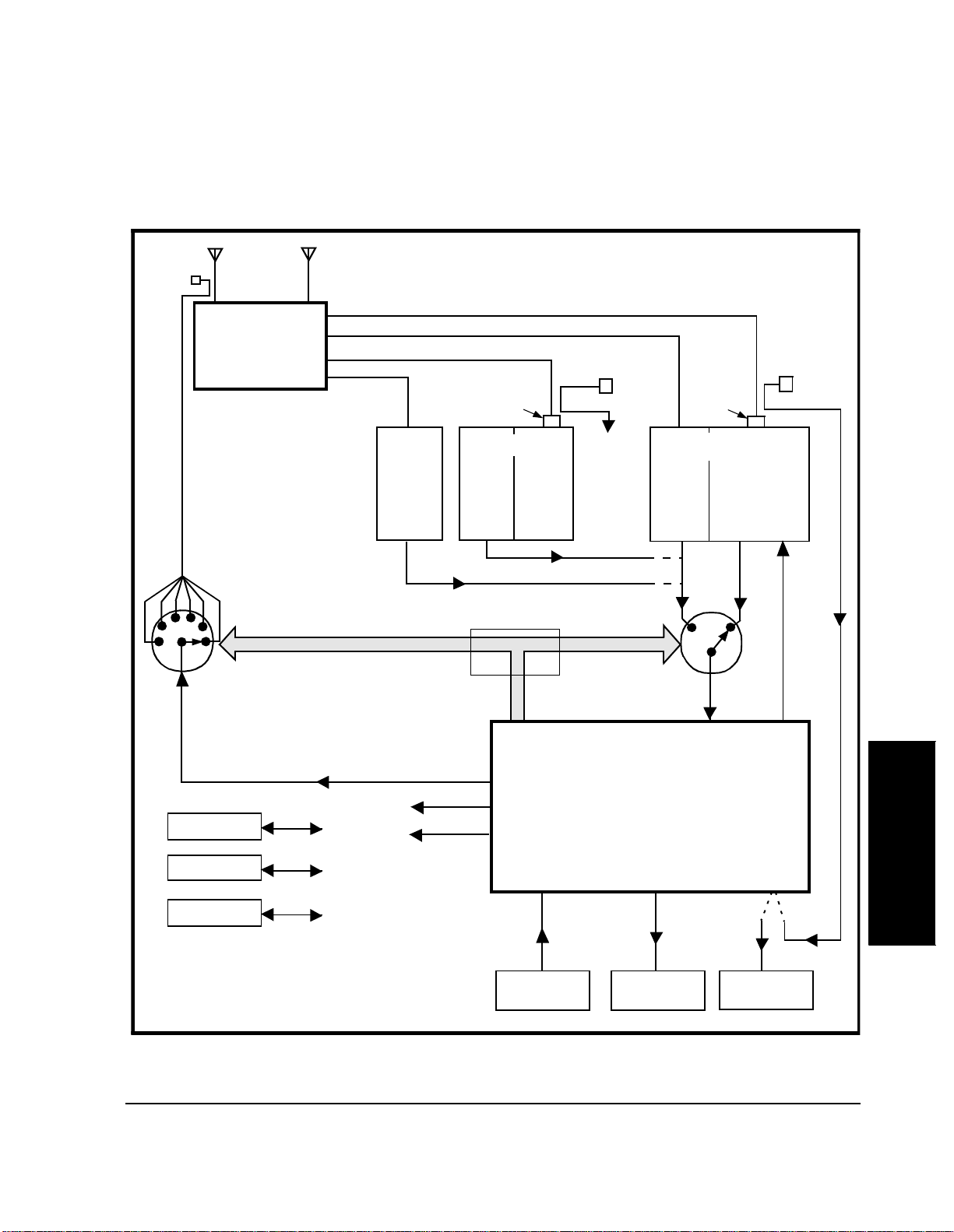
Figure 3 on page 71, is an overall Test System block diagram.
After you have set up your Test System, you will be calibr ating some system
components. Tests s hould be r un wit h the equip ment c onnecte d in the same wa y i t
was when it was calibrated.
70
Chapter 3, Setting Up
Equipment Connections
RF Coupler
(1 of possibly
several.)
RX
ANTENNA(S)
Base
Station
Hardware
RF Switch (1)
TX
TX/RX ANTENNA(S)
SCN(S)
RX
RCV
JK
Harmonic
Filter
SIG(S) To
RX
TX
RCV
JK
Optional Interface
RF Coupler
RF
IN/OUT
Audio S wi tc h (2)
Harmonic
Filter
VOC(S)
RX
RCV
JK
RF Coupler
TX
TESTJKXMT
JK
Radio
Interface
DUPLEX OUT
HP-IB
DISC
PRINTER
PC/TERMINAL
(1)
RF splitter can be used wit h li m ited test
capability. See chapter 3, Configura tion.
(2)
Audio switch not used/controlled if RF
splitte r is us e d in RF p at h .
HP-IB/RS-232
RS-232
RS-232 Serial
HPIB
10 MHz
Reference
Optional
10 MHz
Reference
Figure 3 Overall Test Sy stem Block Diagram
71
RS-232
Serial B
TTYMP #8
CSC Network
Address
Audio
In
HP 8921A
CSC
Audio
Out
RF
IN/OUT
3 MHz
RDM/URDM
Setting Up
Chapter 3
Chapter 3, Setting Up
Equipment Connections
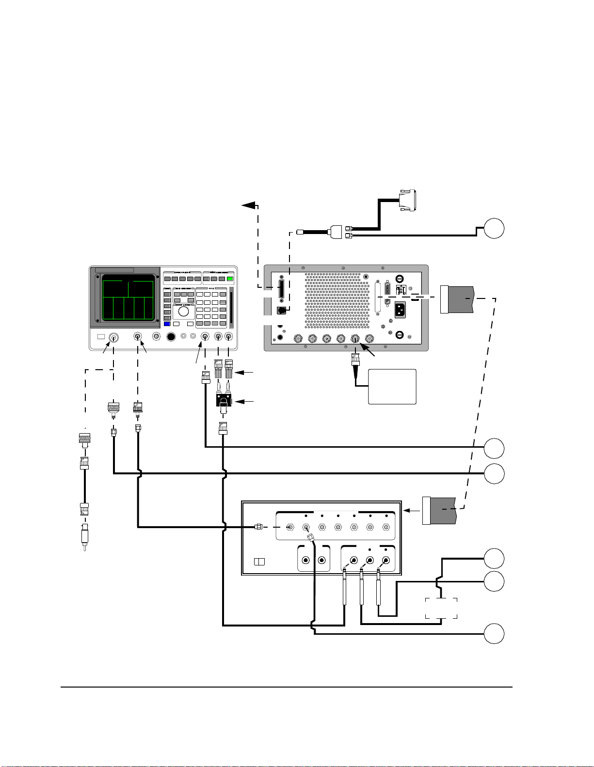
Cell Site to Test Equipment Interconnection
HP-IB (IEEE 488.2)
to Printer, HP 3488A,
or Data Collection PC
HP 8921A Cell Site Test Set
Part 1 of 2
08921-61031
RJ11(m) to RJ11(f)
Back
HP-IB
SERIAL PORT
Splitter
Cable
08921-61038 RJ11 to DB9(f), or
08921-61039 RJ11 to DB25(m)
SERIAL
(Port 9)
SERIAL B
(Port 10)
To Printer, Terminal, or
Data Collection PC RS232
Cable 08921-61015
(25ft) RJ11(m) to RJ11(m)
To RS232 TTYMP #8
CSC Network Address
08921-61013
Ribbon Cable
(10ft) DB37 to DB37
A
DUPLEX OUTRF IN/OUT
AUDIO OUT
Adapter
1250-1250
Adapter
Adapter
1250-0780
Cable (15ft)
08921-61007
Adapter
1250-1853
1250-2015
Cable 08921-61006
(20ft)
To PHONO jacks on
BSC back plane.
* An external 600-ohm load is
required if it is not internally
installed in your Test Set. See
Audio Connections in Chapter 2.
HI
LO
Adap ters 125 0-2164
(AUDIO IN HI & LO)
Adapter 1251-2277
Ground tab on AUDIO IN LO
side.
HP 83202A Opt. K02 Switch Matrix
Optional - Switch needed for Transceiver Tests
83202A OPTION K02 S WITCH MATRIX
H
POWER
OFF ON
Cable 08921-61008 (15ft)
BNC(m) to Mic.(m).
10 MHz REF INPUT
10 MHz Ref .
Cable 08921-61008 (15ft) BNC(m) to Mic.(m).
Cable 08921-61006 (20ft) SMA(m) to SMA(m)
RECEIVER ANTENNA SWITCH
ANT1 ANT2 ANT 3 A N T4 AN T 5 ANT6
DUPLEX OUT
(CS)
(TS)
(CS) (CS) (CS) (CS) (CS)
TX AUDIO
AUDIO SWITCH
AUDIO IN RCV JACK TES T JACK
(TS) (CS) (CS)
10 MHz Ref.
needed for URDM
tests of NAMPS
base station.
600-Ohm
Load*
B
C
D
E
F
Figure 4 Cell Site to Test Equipment Interconnections
72
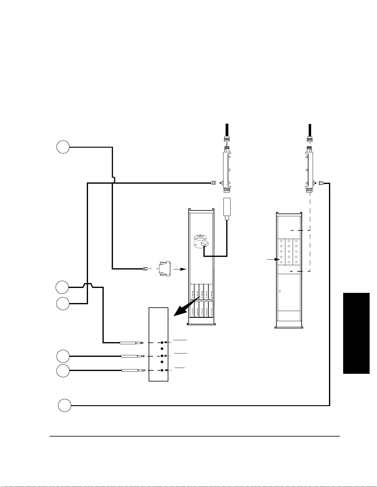
Equipment Connections
Cell Site to Test Equipment Interconnection
Part 2 of 2
Chapter 3, Setting Up
Cable 08921-61015
(25ft) RJ11(m) to RJ11(m)
A
Cable
08921-61006
(20ft)
B
(1 of possibly several in
TX Harmonic Filter
Base Station
Bay
Adapter
08921-61016
RJ11(f) to DB25(m)
To RS232 TTYMP #8
CSC Network Address
To TX Antenna(s)
RF Coupler
0955-0711
bay. See NOTE 1.)
See NOTE 1
(1 of possibly several
in rack. See NOTE 1.)
Site Filter
Rack
Filters
To RX Antenna(s)
RF Coupler
0955-0711
See NOTE 2
See NOTE 2
C
Cable 08921-61040
Cable
08921-61008
(15ft) BNC(m)
to Mic.(m)
VOC
SIG, VOC, SCN
D
Cable 08921-61040
E
Mic.(m) to Mic.(m)
Cable 08921-61006 (20ft) SMA(m) to SMA(m)
VOC
F
73
VOC,
SIG, or
SCN
EQUIP XMT LINE JK
EQUIP RCV LINE JK
TEST JK
NOTE 1: It is recommended that
each ant enna line in the bay and
rack have its own RF Coupler .
NOTE 2: Depending on the site
filter-rack used, RF couplers can
be inserted before or after filters.
Setting Up
Chapter 3

Chapter 3, Setting Up
Equipment Connections
Receiver RF Connections
An RF coupler must be installed between each of the recei ve antennas and base
station receiver inputs. See figure 4 on page 72 for a description of these
connections. RF cables connect each of the coupled ports to an RF N-way switch
or splitter. The switch will have two selected ports if the site is an omni site, and
six if it is a sectored site. The common port of the switch or splitter is connected
to the Test Set DUPLEX OUT connector. See "Radio Interface Connections" on
page 79 for details of the connection of the Radio In terface to the RF N-Way
switch.
CAUTION: The applica tion of RF p ower greater tha n 200 milliwatt s (mW) (or +23 dBm) can damage
the Test Set DUPLEX OUT port . Make certai n that signal s applied to t his port are less than
200 mW. If an RF power higher than 200 mW is applied, an overpower relay will trip.
Disconnect t he RF si gnal, or tur n it off, press MEAS RESET or tur n t he Tes t Set powe r of f
and then on to reset it, and then reconnect the RF signal, or turn it on again.
Signals that affect the equipment being measured can be picked up by the RX
antennas. To prevent this, terminate the RF coupler when performing tests of the
SIG unit and scan receivers.
In measurements on voice channel receivers, antennas ordinar ily may be left
connected to the RF couplers. Interference may be detected by turning up the
speaker volume of the Test Set. The interfering signal might be the result of a
problem in the frequency plan. If it is impo ssible to proceed with measurements,
terminate the RF coupler port leading to the antenna using a 50-ohm load.
Transmitter RF Connections
An RF coupler must be installed between each cell site transmit antenna and its
associated harmonic filter if you wish to perform any test in the In-Service
Optimization sta te. See fi gure 4 on pag e 72 for a desc ription o f these conne ctions .
A small amount of powe r is ava ilable at t he coup led port a nd is ap plied to the Te st
Set RF IN/OUT connector.
While testing the SIG unit, a high-power load must be placed on the RF coupler
output leading to the ant enna. It mu st be cap able of h andling at least 30 watts . The
load is necess ary to prevent the SIG unit transmitte r signal from being r ad iated to
mobile stations.
74

Chapter 3, Setting Up
Equipment Connections
Audio Connections An SPDT switch must be installed so that the Test Software can automatically
apply either the TEST JK of the tra nsmi tter or the EQUIP RCV of the receiver to
the Test Set AUDIO IN. See figure 4 on page 72 for a description of these
connections. A 600-ohm load must be connected across the EQUIP RCV, if your
Test Set does not have a built-in switcha ble 600-ohm floating load. This inte rn al
load is included in all Test Sets shipped after October 1992. Determine if it is
built-in by looking for its co ntrol field on the AF ANALYZER screen. The field
is labelled
the screen includes these three choices, the switchable load is inst alled.
The HP 11807B Option 040 Test Software selec ts a floati ng AUDIO IN LO if the
Test Set does not have an internal 600-ohm load.
See "Radio Interface Connections" on page 79 for details of the connection of the
Radio Interface to the audio path switch.
The transmitter EQUIP LINE JACK is connected to the Test Set AUDIO OUT
connector with a coaxial cabl e. You might wish to route this connection through
the switch box.
Audio In Lo and has three choice s: Gnd, Float, and 600 to HI. If
Connection fo r RS-232 Base Stat ion Co ntrol
CAUTION: RJ-11 cable and adapters might be wired in several ways . Verify the connect ions bet ween
Serial Port Connections for Data Collection
The HP 11807B Option 040 Test Software supports RS-232 control of the base
station via the TTYMP #8 CSC Network Address connection. Other connections
are not supported. The Test Set has a rear-pa nel RJ-11 connector for serial
communication. See figure 5 on page 76. It has two serial ports on it, Serial A
port and Serial B port. Serial B port is used for base station control and
messaging.
the Test Set RJ-11 conne ctor and the DB-25 base station connector.
The connections between the Test Set RJ-11 connector and the DB-25 TTYMP
#8 CSC Network Address connector are shown in figure 6 on page 77
The Test Software is capable of uploading test results to an external computer.
One way to accompl ish this is by runn ing a terminal pr ogr am on a laptop or other
computer and using terminal logging to save the information sent to the Test Set
Serial port. See figure 5, "Connector on Test Set Rear Panel," on page 76 and
figure 6, "Adapters for Base Station Control," on page 77.
Setting Up
Chapter 3
75

Chapter 3, Setting Up
Equipment Connections
Printer Connection A seri al printer may be connected to the Test Set Serial port. An HP-IB printer
may be connected to the Test Set rear-panel HP-IB connector.
See "Serial Port Configuration" on page 109 for informati on on how to set the
Test Set Serial port settings to match the printer settings. (See also"Appendix:
Cable Wiring Diagrams for Data Collection to PC and Printer" on page 233).
Serial Port Location
A serial pri nter may be atta ched to t he Ser ial por t. Use the following figur e for p in
information and the next figure for adapter information.
Connector on Test Set Rear Panel
Transmit B
6
5
4
3
2
1
Transmit A
Ground
No Connect
Receive A
Receive B
Figure 5 Connector on Test Set Rear Panel
76

HP 8921A Test Set
Serial Port
6
5
4
3
2
1
Chapter 3, Setting Up
Equipment Connections
Adaptors
For Base Station Control
RJ-11 (F) to DB-25 (M)
see Diagram A
RJ-11 Splitter
For PC or Printe r
RJ-11 (F) to DB-25 (M)
see Diagram B
Diagram A
RJ-11 (F)
1 2 3 4 5 6
Transmit BReceive B Gnd.
DB-25 (M)
Pin 2 Pin 3
Pin 1
Pin 14 Pin 25
Pin 20
Pin 7
Pin 8
Pin 13
Diagram B
RJ-11 (F)
1 2 3 4 5 6
Transmit AReceive A
Gnd.
DB-25 (M)
Pin 2
Pin 1
Pin 14 Pin 25
Pin 3
Pin 20
Pin 7
Pin 8
Pin 13
DB-9 (F) NOTE:
pins 1, 4, & 6 jumpered together, and
pins 7 & 8 jumpered together
For a PC
RJ-11 (F) to DB-9 (F)
see Diagram C
Diagram C
RJ-11 (F)
1 2 3 4 5 6
Gnd.
DB-9 (F)
Pin 3
Pin 5
Pin 9
Transmit AReceive A
Pin 2
Pin 1
Pin 6
Setting Up
Chapter 3
Figure 6 Adapters for Base Station Control
77

Chapter 3, Setting Up
Equipment Connections
Parallel Port Location
Pin 1
nStrobe
Data 1
Data 2
Data 3
Data 4
Data 5
Data 6
Data 7
Data 8
nAck
Busy
PError
Select
A parallel prin ter may be a ttached to t he paralle l por t. Use the f ollowing f ig ure for
pin information.
Pin 14
nAutoFD
NFault
nInit
nSelectn
Signal Ground
Pin 13
Pin 25
Figure 7 Test Set Parallel Port Connections
Disk Drive Connections
A disk drive may be attached to the rear-panel HP-IB connector. See "Data
Collection" on page 113.
78

Chapter 3, Setting Up
Equipment Connections
Radio Interface Connections
CAUTION: Damage to the Test Set can result if the RF or Audio switches generate transients that are
The following p ins on the Radio I nte rface connector are used to control switches:
1 - GND
19 - Parallel Data Out - D0 - Pos. 1 on the RF switch
20 - Parallel Data Out - D1 - Pos. 2 on the RF switch
21 - Parallel Data Out - D2 - Pos. 3 on the RF switch
22 - Parallel Data Out - D3 - Pos. 4 on the RF switch
23 - Parallel Data Out - D4 - Pos. 5 on the RF switch
24 - Parallel Data Out - D5 - Pos. 6 on the RF switch
25 - Parallel Data Out - D6 - DPDT audio relay
26 - Parallel Data Out - D7 - DPDT audio relay (opposite polarity as pin 25)
conducted int o the T es t Set via the Radio Interface connector. It might be necessary to
install di odes on the Radio Interface control lines to suppre ss transients caused by the
switches. Refer to the switch manual for the proper interface to TTL or CMOS control
lines.
There are Radio Interface connector pins that are used for other purposes not
listed above. If you plan to con nect to these line s, see “Conne ctor , Key, and Knob
Descriptions” in the Test Set User’s Guide .
A buffer might be required between the switch and the Radio Interface connector.
See "Switch Control Input Buffer," in chapter 2, on page 62.
The Radio Interface Card provides either a 5.1-volt or user selectable high state
logic output voltage.
79
Setting Up
Chapter 3

Chapter 3, Setting Up
Equipment Connections
The Parallel Data Out lines are open collector outputs with 3.16-kilohm internal
pull-up resistor s. The resistors are connected between the col lectors of the drive
transistors and a logic voltage that may supplied either intern ally or externally.
The internally suppli ed voltage is approximately 0.6 volt le ss than the externally
supplied voltage. The external voltage is applied to pin 9 of the Radio Interface
connector, and may be between 5.1 volts and 20 volts. The maximum loading on
the voltage is 145 ohms to ground. If no voltage is applie d, an internal 5.1-volt
source is used as the logic voltage. The characteristics of the paral lel lines are:
High state out put: 3. 16-kilohm pul l-up to the logi c voltage . See t he previou s paragraph.
Output si n k cu rrent (low state, output voltage ≤ 1.5 volts): 6 mA mini mum, 16 mA
typical
Series chokes: 4.6 µ H for RFI cont rol on all lines.
Clamp diodes for ESD protection: The applied voltage must not exceed the logic
voltage plus 0.6 v olt, or be less than − 0.6 volt.
DC Power to the RF and Audio Switches
DC power must be supplied t o the RF and audio switches from a separate source.
The Radio Interface Card cannot supply such power. Refer to the switch
documentation for power requirements.
80

Determining Calibration Paramete rs
Methods of measurement in this section determine RF losses and inaccuracies in
your Test System. You must record the result ing calibration factors and enter
those as parameters in the fields of the TESTS (Te st Parameters) screen. The Test
Software w ill then use thes e cal ibr at ion factors when the te s ts are run .
If you are using a switch to automatically change RF paths, you must make
entries into the TESTS (Externa l Devices) screen before you begin these
methods. Entries are required for the Test Software to control the switch in
“TEST_08 - Manual Switch and Calibration Aid”. See "Determining Calibration
Parameters" on page 81.
Chapter 3, Setting Up
Determining Calibration Parameters
Transmitter Path Loss Calibration
This procedure is used to obtain values for the parameter(s) TX path loss to
harmonic filter 1 (to) 8.
See "Conventions Used," in chapter 1, on page 49 for descriptions of the terms
select and enter. The terms are used in the ste ps in these procedures that make
entries to the Test Software .
When making a tra nsmitter power measurement with the Te st S et power meter or
spectrum analyzer, the following losses or inaccuraci es will be present in the
measured results:
a) Cable losses.
b) Directional couple r los s es .
c) Spectrum analyzer or pow er meter absolute accuracy.
d) Spectr u m analyz er or power meter flatness accuracy.
The following procedure use s an externa l, highly accurate, power meter to
determine a calibrat ion fac tor that will correct for the errors listed in a through c
above. A single factor for each TX path loss is obtaine d. No correction is
provided for changes in loss versus frequency. If the RF coupler coupling is low
enough to allow the use of the power meter in the Test Set, this calibration factor
will cover Test Set power meter errors. Otherwise, the spectrum analyzer error
will be covered.
Setting Up
Chapter 3
81
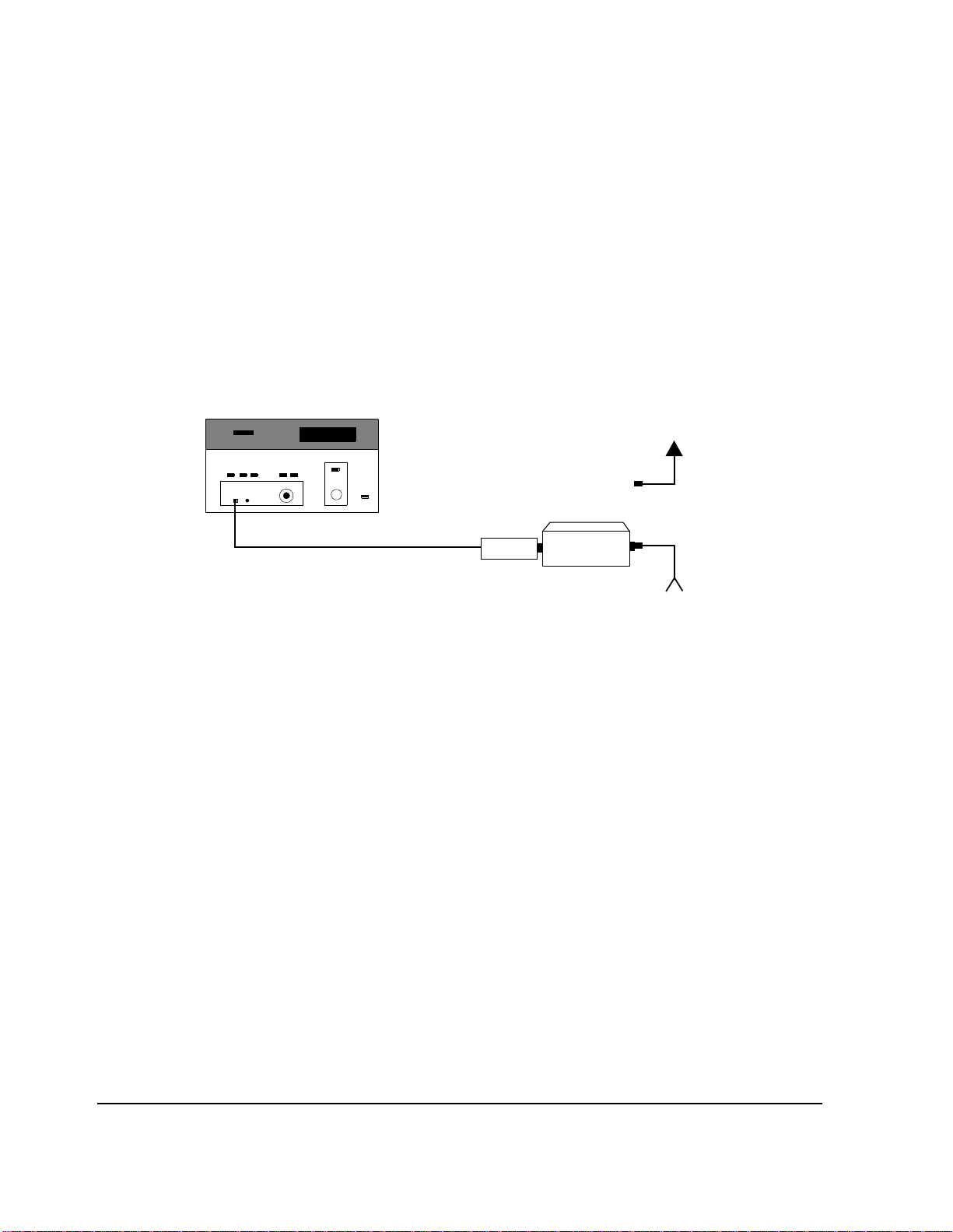
Chapter 3, Setting Up
Determining Calibration Parameters
To determine this
calibration factor:
1. See figure 8 . Zero the power meter a nd set the c alibrati on fa ctor i f nece ssary. Place a.
high-power atte nuator at the output of the TX harmonic fi lter. Connect a power meter
sensor to the output of t he attenuator. The attenuat or might not be require d if the power
meter and sens or range is correct fo r the power being measure d. Make cert ain that t here
are no extra cables in the setup. The atten uator sh ould have a 50-ohm input and output
impedance, with a VSWR less than 1.1:1. Record the value of the attenuation as
ATTVALUE in dB.
Power Met e r
To Antenna
Attenuator
Sensor
From Base Station TX
Harmonic Filter (N) Output
Figure 8 Transmitter Path Loss - POWERREF Measurement
2. Key a single transmitter, with no modulation, and measure the power on the power
meter. Record this reading as POWERREF in dBm.
3. De-key the transmitter.
82
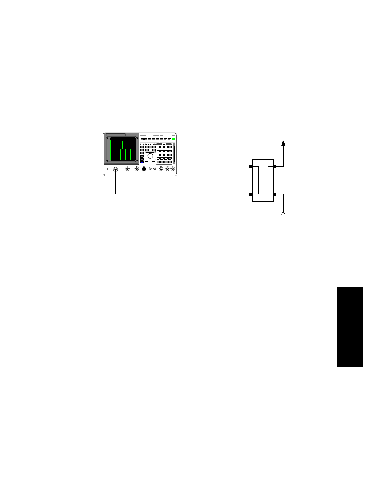
RF IN/OUT
Chapter 3, Setting Up
Determining Calibration Parameters
4. See figure 9 . Con nect t he T X harmon ic fil ter outp ut to the RF co upler input. Con nect
the Test Set RF IN/OUT, using a standard test cable, to the coupled port of the RF
coupler in the TX antenna line.
HP 8921A
To Antenna
Coupler
Standard TX Test Cable
Harmonic Filter (N) Output
Figure 9 Transmitter Path Loss - POWER8921 Measurement
5. Re-key the sam e transmitt er that was keyed in step 2.
6. If the param eter TX voice/si gnal pwr us e is set to 0, transmitter power will be measured
on the spectrum analyzer. If the parameter is set to 1, measure the transmitter power on
the Test Set power meter, record it as POWER8921, and proceed to step 7.
From Base Station
Setting Up
Chapter 3
83

Chapter 3, Setting Up
Determining Calibration Parameters
NOTE: The steps a through r list ed below, may be performed autom atically by runnin g “TEST_08
- Manual Switch and Calib ration Aid” and selecting Read the spec. analyzer TX
path calibration.
a. Press the PRESET key.
b. From the To Screen menu, select SPEC ANL. The SPECRUM ANALYZER
screen w il l app ear.
c. From the Controls menu, select Main. The Main menu will appear at the
bottom of the scr een.
d. Select Center Freq. Enter a value equal to the tran smitter frequency.
e. Select Span. Enter 50 kHz.
f. From the Controls menu, select Marker. The Marker menu will appear at the
bottom of the scr een
g. Under the first Marker To field, select Peak.
h. Under the second Marker To, select Ref Level.
i. From the Controls menu, select Auxiliary. The Auxiliary me nu will appear
at the bottom of the screen.
j. Under Sensitivity, select the lower field and choose 2 dB/div.
k. From the Controls menu, select Marker.
l. Under the first Marker To, select Peak.
m. Under the second Marker To, select Ref Level.
n. From the Controls menu, select Main. The Main menu will appear at the
bottom of the scr een.
o. Select Ref Level.
p. Under Ref Level, select the field and enter a value to increase the reference level
on the spectrum analyzer by 8 dB. Use the numeric keypad or the cursor control
knob. You may c hange t he resol uti on of the refere nce l evel a djus tment by pre ssing
the INCR ÷ 10 key or th e INCRx10 key.
q. Verify that the peak of the signal is close to the center of the spectrum ana lyzer
display.
r. From the Controls menu, select Marker. The Marker menu will appear at the
bottom of the scr een
s. Under the first Marker To field, select Peak.
t. Record the Marker Lvl (in the upper righ t corner of the scre en) as POWER8921
in dBm.
84

Chapter 3, Setting Up
Determining Calibration Parameters
7. De-key the tran smitter.
8. Calculate the cali bration parameter using the following formula:
Calibration parameter = POWERREF + ATTVALUE − POWER8921
9. Enter the value(s) of the calibration param eter(s) into the p arameter(s) TX path loss to
harmonic filter 1 (to) 8.
Receiver Path Loss Calibration
This procedure is used to obtain values for the parameter(s) RX path loss to
antenna 1 (to) 6.
When making a re ceiver sensitivity measurement wi th the Test Set, the following
losses or inaccuraci es will be present in the measured results:
a) Cable losses.
b) Directional couple r los s es .
c) Test Set output level ac curacy.
The following procedure will use an exte rnal, highly accurate power meter to
determine a calibrat ion fac tor that will correct for the errors a and b listed above.
A single factor for each RX antenna is obtained. No correction is provided for
changes in loss versus frequency.
Setting Up
Chapter 3
85
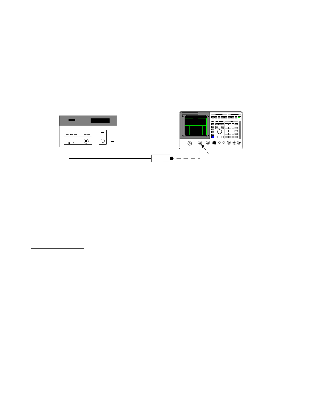
Chapter 3, Setting Up
Determining Calibration Parameters
To determine this
calibration factor:
Figure 10 Receiver Path Loss - POWERREF Measurement
NOTE: Steps a through f below may be performed automatically by running “TEST_08 -Manual
1. See figure 10. Zero the power meter and set the power meter calibration factor if
required. Connect the power meter sensor to the Test Set DUPLEX OUT.
Power Meter
Sensor
2. Set the Test Set to generate an unmodulated RF signal at an amplitud e su fficient to
measure the path and coupler loss with the power meter a nd power sensor being used.
Do this by performing the following steps.
Switch and Calibration Aid” and sel ecting Set the HP 8921A for RX path
calibration.
HP 8921A
DUPLEX OUT
a. Press PRESET.
b. From the To Screen menu, select RF GEN. The RF GENERATOR screen will
appear.
c. Under RF Gen Freq, select the field and enter 834.5 MHz.
d. Under AF Gen1 To, selec t the lower field and pre ss the Tes t Set ON/OFF key to
set it to O F F .
e. Under Output Port, se lect the field and press the cursor control knob to make
Dupl underlined. (This se lects the DUPLEX OUT port.)
f. Under Amplitude, select the field and enter the value as required by the couple r
loss and sensor sensitivity. You must not change this amplitude for the remainder
of this procedure.
3. Record the pow er meter reading as POW ERREF in dBm.
86
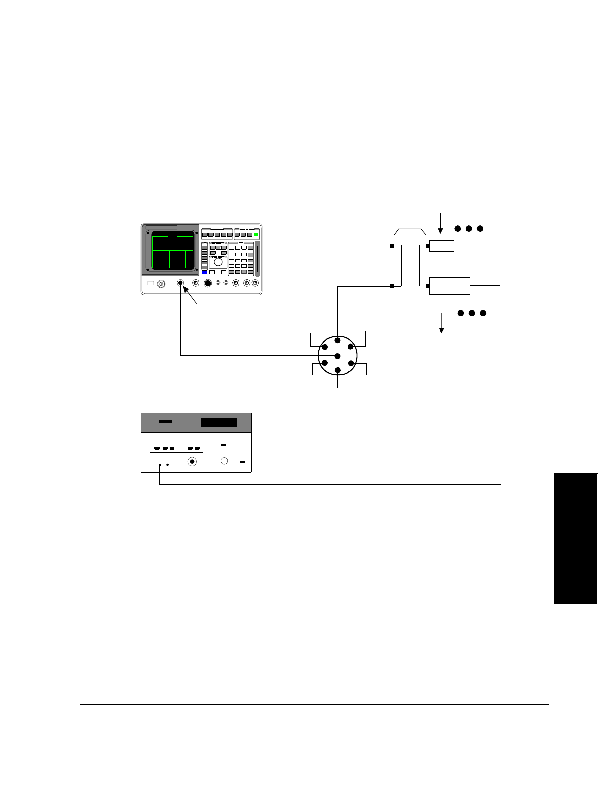
Chapter 3, Setting Up
Determining Calibration Parameters
4. See figure 11 . Conne ct the Test Set DUPLEX OUT to the common port of the RX
antenna switch. Terminate the RF coupler port leading to the antenna. Conne ct the
power meter sensor to the RF coupler port that normally attaches to the receiver input.
HP 8921A
DUPLEX OUT
Power Met e r
Coaxial Switch
From Antenna
Coupler 1
50 Ohm
Termination
Sensor
1
6
2
To Receive r
5
3
4
Figure 11 Receiver Path Loss - POWERRERCEIVER Measurement
5. Switch the coaxial swi tch to the desired position, either manually or by using
“TEST_08 - Manual Switch and Calibration Aid”. If you are using TEST_08, verify
that the switc h is properly configured, with the right ent r ies made to the TESTS
(External Devices) screen.
6. Record the po w er meter r eading as POWERRECEIVER in dBm.
7. Calculate the ca libration parameter usi ng the fo llowing formu la: Calibrat ion param eter
= POWERREF − POWERRECEIVER
8. Repeat steps 5 through 7 for the other antenna paths.
9. Enter the values resulting from these steps into the para mete r(s) RX path loss to
antenna 1 (to) 6.
87
Setting Up
Chapter 3
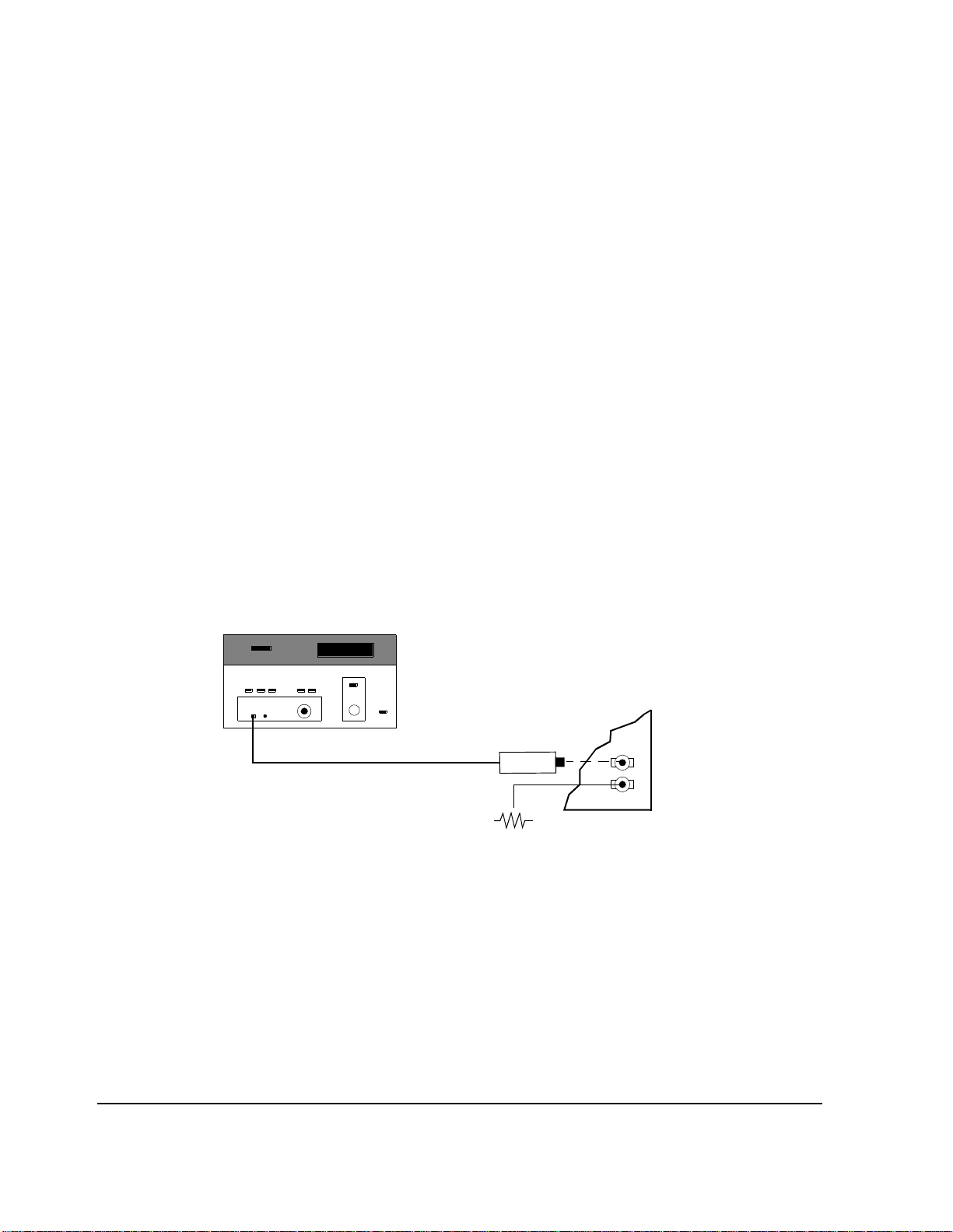
Chapter 3, Setting Up
Determining Calibration Parameters
Reference
Distribution
Module Level
Correction Factor
To determine this
calibration factor:
The method of measurement de scribed here may be used to obtain a value for the
parameter RDM level correction factor. The Te st Software will use th is cor recti on
factor to enhance the accuracy of 3-MHz leve l measurements using the Test Set
spectrum analyzer.
In the procedure, you will measure the level of the 3-MHz RDM/URDM signal
using a power meter. You will then measure it on the Test Set spectrum analyzer.
The spectrum analyz er will cente r the 3-MHz signal on th e displa y. Then you will
determin e the dif fere n ce b etw een the power meter reading and the spectrum
analyzer reading.
1. Zero the power meter if required.
2. Set the power meter calibration factor if requi red.
3. Remove the 50-ohm load that is on the URDM/RDM Phono #2 jack.
4. See figure 12 . Connect the power meter sensor to an ada p ter that is atta ched to the
URDM/RDM Phono #2 jack.
Power Meter
BSC Backplane
Sensor
50 Ohms
Figure 12 RDM Level Correction - POWERREF Measurement
5. Record the power meter reading in dBm as POWERREF.
6. Disconnect the power meter sensor.
88
3 MHz
Outputs

RF IN/OUT
Chapter 3, Setting Up
Determining Calibration Parameters
7. See figure 13. Conne ct a standard test cable between the 3 MHz Phono #2 jack, and
the Test Set RF IN/OUT connector.
HP 8921A
BSC Backplane
Standard Test Cable
(Used when measuring RDM level
and calibrat ion)
3 MHz
Outputs
50 Ohms
Figure 13 RDM Level Correction - POWER8921 Measurem ent
8. Perform the following steps:
NOTE: The steps a t hrough r, li sted below, may be performed automaticall y by running “ TEST_08
- Manual Switch and Calibration Aid” and selecting Read the spec. analyzer
RDM calibration.
a. Press PRESET.
b. From the To Screen menu, select SPEC ANL. The SPECRUM ANALYZER
screen w il l app ear.
c. From the Controls menu, select Main. The Main menu will appear at the
bottom of the scr een.
d. Select Center Freq. Enter 3 MHz.
e. Select Span. Enter 50 kHz.
f. From the Controls menu, select Marker. The Marker menu will appear at the
bottom of the scr een
Setting Up
Chapter 3
g. Under the first Marker To, sele ct Peak.
h. Under the second Marker To, select Ref Level.
89

Chapter 3, Setting Up
Determining Calibration Parameters
i. From the Controls menu, select Auxiliary. The Auxiliary me nu will appear
at the bottom of the screen.
j. Under Sensitivity, select the lower field and enter 2 dB/div.
k. From the Controls menu, select Marker
l. Under the first Marker To, select Peak.
m. Under the second Marker To, select Ref Level.
n. Select Ref Level.
o. Under Ref Level, select the field and enter a value to increase the reference level
on the spectrum analyzer by 8 dB. Use the numeric keypad or the cursor control
knob. You may c hange t he resol uti on of the refere nce l evel a djus tment by pre ssing
the INCR ÷ 10 key or th e INCRx10 key.
p. Verify that the peak of the signal is close to the center of the spectrum ana lyzer
display.
Combi n e r to T e st Set Path Loss Factor
q. Under the first Marker To, select Peak.
r. Record the Marker Lvl (in the upper righ t corner of the screen ) as POWER8921
in dBm.
9. Calculate t he ca librat ion para meter usi ng the f ollo wing formu la: Cali bration param eter
= POWERREF − POWER8921
10. Enter the value obtai ned int o the parame ter RDM leve l c orre ct io n facto r. Make c ertai n
to enter als o the sign of the value. The value o btained in step 9 is added to spectrum
analyzer readings ma de by the Test Software, thus im proving accuracy.
This calibration factor is used in “TEST_06 - Combiner Adjustment”. It is the
value entered into the parameter TX path loss to combiner for adjustment.
If you leave an RF coupler in the measurement path, you may obtain the value of
the parameter by copying it from the value of the parameter T X path loss to
harmonic filter (n), where “n” is the harmonic filter that you are using. You must
use the same measurement method, power meter or spectrum analyzer, for
calibration and tes ting.
If you do not use the RF coupler, the calibration factor must cover the loss in the
cable used between the harmonic filt er output and the Test Set RF IN/OUT
connector. You must measure the loss of this cable. One way to do this is to use
the method in "Receiver Path Loss Calibration" on page 85, replacing the RX
antenna switch, RF coupler, and cabl es with the cable that you are measuring.
Enter the loss value into the parameter TX path loss to combiner for adjustment.
90

Procedures
Chapter 3, Setting Up
Procedures
A Procedure is a collection of parameters, pass/ fail limits, and a test sequence, all
saved in a file that can be run to customize the Test Software to a specific
application. The application, for instance, might be a particular cell site or base
station. After you have create d a Procedure, store the file on an SRAM card or
disk.
This section describe s the use of such Proc edures to save and retrieve files.
You should identify any Procedur e that you wish to sa ve with a name that refers
to a particular application. In use, you select the Procedure for the application
after you connect the Test Set. It would pro babl y be appropriate to have a
Procedure, or perhaps a set of Proced ures, for each of the cell sites that you
maintain.
You are not requir ed to save a TEST se quenc e in a Proc edure. Each of t he TESTs ,
TEST_01 through T EST_11, i s a st and-alon e TEST. After you se lect a Proce dure,
you may select which of the TESTs that you wish to run.
When you save a Procedure, you save only parameters, pass/fail limits, and a test
sequence. The SRAM card or disk must a lso c ontain a Library f ile. A Library f ile
contains the names of all of the pa rameters, pass/fai l limits and TESTs that are in
the Test Software. Ordinarily, the Library that you use will be the Library tha t is
supplied with your Test Software . I t is named
MOT_CS. When you save your
Procedure, the Library will be saved automatically on the same SRAM card or
disk.
The Procedure supplied with your Test Softwa re will be the first procedure that
appears in the
Filename:
Choices: menu when you select the Select Procedure
field. It is named MOT_CS and will be displayed if your Test
Software O TP card is ins er te d.
Procedures do not conta in actua l program steps or code. Thes e software steps are
contained in a code file . The code f ile
MOT_CS is on the Test Software OTP card.
Setting Up
Chapter 3
91

Chapter 3, Setting Up
Procedures
Saving a Procedure After you have set up the Test Software for a particular application and thereby
created a Procedure, you may save the Proce dure to an SRAM card, the internal
RAM disk, or an external disk drive.
NOTE: The SRAM card or disk that you use must be initialized before its first use. See
"Initializi ng an SRAM Card" on page 115 or "Initializing a Disk" on page 114 in
"Data Collection" on page 113. If you are using a disk drive, you might be required
to enter the
Devices) scree n. I t will be us ed when the
on the TESTS (Main Menu) screen is
See "Conventions Used," in chapter 1, on page 49 for descriptions of the terms
select and enter.
External Disk Specification into the TESTS (External
Select Procedure Location: field
Disk.
92

Chapter 3, Setting Up
Procedures
To Save a
Procedure:
1. Press TESTS. The TESTS (Main Menu) screen will appear.
2. On the TESTS (Main Menu), scre en verif y tha t the Libra ry i s the o ne that was shipp ed
with your Test Software. Th e first or only ite m under Choices: should be MOT_CS.
If it is not, loa d the MOT_CS Procedure. See "Gett ing Started," in chapter 1, on page
34.
3. From the CUSTOMIZE TEST PROCEDURE: menu, select Proc Save/Delete
Procedure. The TESTS (Save/Delete Procedure) screen will appear.
4. Select Select Procedure Location:. The Choices: menu will appear in the
lower right-hand area of the screen.
5. From the Choices: menu, select the desi red l ocati on. If the c ard or di sk ha s not b een
used before, it must be initialized before a file can be saved. See
SRAM Card" on page 115
disk, see “Memory Car ds/Ma ss Storag e ” in the Test Set User’s Guide.
6. Select Enter Procedure Filename:. The Choices: men u w ill re ma i n in t h e
lower right-hand area of the screen.
7. Using the list of characters in the Choices: menu, enter a filename. The filename
must be nine characters or less.
8. When filename is complete, select Done from the menu.
9. If you sele cted Card, ins ert an i nitiali zed SRAM ca rd into t he sl ot on the T est Set f ront
panel.
in "Data Collect ion" on page 113. To init iali ze a RAM
"Initializ ing an
10. Verify that the card or other medium is not write-protected. See "Mem o r y Ca rd s , " in
chapter 2, on page 53.
11. Sel ect Enter Description for New Procedure:. The Choices: menu
will remain in th e lo w er righ t -h a nd area of th e scree n.
12. Using the list of characters in the Choices: menu, enter comments.
13. When the comments are complete, select Done from the menu.
14. Under Procedure Library:, select Current (Current underline d). The name of
the Library will be displayed on the TESTS (Main Men u) screen. If you wis h to check
this, press k5 (Main Menu).
15. Under Code Location:, select memory Card, RAM disk, or external Disk. When
a procedure is run, the TESTS subsyste m will check thi s location for a code file if it is
not resident in the Test Set battery-bac ked-up memory. This location will usually be
the Test Software OTP card.
16. Press k1 (Save Proc). A Procedure will be saved at the locati on that you selected.
93
Setting Up
Chapter 3

Chapter 3, Setting Up
Procedures
Loading a Procedure
To load a
Procedure:
Deleting a Procedure
To delete a
Procedure:
If you have saved a Procedure on some storage medium, you may retrie ve it and
load it into the Test Set battery -bac ked-up memory.
1. Press TESTS. The TESTS (Main Menu) screen will appear.
2. Select Select Procedure Location:. The Choices: menu will appear in the
lower right-hand area of the screen.
3. From the Choices: menu, select the location whe re the Procedur e is stored: memory
Card, RAM disk, or external Disk drive.
4. Select Select Procedure Filename:. The Choices: menu wil l r em a in in
the lower right-hand area of the screen.
5. From the Choices: menu, select the Procedure file that you wish to load.
6. Read the Description: field t o ensure that th e loaded Procedure file is the co rrect
one.
If there is a Proced ur e on an SRA M card , RAM disk, or external d isk drive t h at
you no longer need, you may delete it.
1. Press TESTS. The TESTS (Main Menu) screen will appear.
2. From the CUSTOMIZE TEST PROCEDURE: menu, select Proc Save/Delete
Procedure. The TESTS (Save/Delete Procedure) screen will appear.
3. Select Select Procedure Location:. The Choices: menu will appear in the
lower right-hand area of the screen.
4. From the Choices: menu, select the desired location.
5. Select Select Procedure Filename:. The Choices: menu w il l r em ain in
the lower right-hand area of the screen.
6. From the Choices: menu, select the name of the procedure that you wish to delete.
7. Press k2 (Del Proc).
8. Answer the prompt by pressing the SHIFT key and then the YES key if the entries are
correc t. The Procedure will be deleted.
94

Chapter 3, Setting Up
Procedures
Securing a Procedure
After you have set up your Test Software with a testing order, channel
information, test parameters, and pass/fail lim its, thereby creating a Procedure,
you may wish to secure it. This will prevent the vie wing and chan ging of those
functions. In this process, you may select the items that you wish to secure. The
IBASIC SECURE_IT program is provided in the Test Set firmware to do this .
You may secure the Procedure that is suppl ied with the Test Software. It is
shipped un-secured.
To secure a
Procedure:
NOTE: RAM refers to the RAM di sk me mory wit hin the tes t se t. Bef or e se lect ing RAM, y ou mus t
1. Press TESTS. The TESTS (Main Menu) screen will appear.
2. Select Select Procedure Location:. The Choices: menu will appear in the
lower right-hand area of the screen.
3. From the Choices: menu, select ROM.
4. Select Select Procedure Filename:. The Choices: menu wil l r em a in in
the lower right-hand area of the screen.
5. From the Choices: menu, select IB_UTIL (or SECURE_IT).
6. Press k1 (Run Test).
7. Select the location of the Procedure that you wish to secure: k1 (memory Card) or
k2 (RAM.)
initialize the RAM as a disk. See "Initializing an SRAM Card" on page 115.
8. Proceed with the on-line instructions. You may wis h to se cure only one of the items,
such as pass/fail limits.
9. When you are prompte d to enter t he pass number, enter any sequence of numerals
0 through 9 using the DATA keypad. Enter 9 digits or less.
95
Setting Up
Chapter 3

Chapter 3, Setting Up
Procedures
Un-Securing a Procedure
After you have secured a Procedure, you may un-sec ure it. In this process, you
may select the items that you wish to un-secure. The IBASIC SECURE_IT
program is provide d in the Test S et fir mware to do this. To u n-secure a proce dure,
you must know the
To un-sec ure a
Procedure:
NOTE: If the procedure includes any item that is secured, you will be prompte d for the pass
1. Press TESTS. The TESTS (Main Menu) screen will appear.
2. Select Select Procedure Location:. The Choices: menu will appear in the
lower right-hand area of the screen.
3. From the Choices: menu, select ROM.
4. Select Select Procedure Filename:. The Choices: menu wil l r em a in in
the lower right-hand area of the screen.
5. From the Choices: menu, select IB_UTIL (or SECURE_IT).
6. Press k1 (Run Test).
7. Select the location of the procedur e that you wish to un-s ecure: k1(memory Card) or
k2 (RAM.).
8. Enter the name of the procedure that you wis h to un-secure.
number.
pass number.
9. Proceed with the on-li ne instructio ns. Select the ite ms that you wish to un-secure.
10. When you are prompted, enter the pass number using the DATA keypad.
96

Chapter 3, Setting Up
Procedures
Copying a Procedure
If you wish to have more than one copy o f Procedure s t hat you u se often , you may
copy these at any time.
Using the COPY_PL ROM Program
The program COPY_PL in Test Set ROM copies Procedure and Library files onto
an SRAM card. It may also be used to initializ e an unini tialize d SRAM card. This
program does not copy executable program (code) files. The memory card used
must be of the SRAM (Static Random-Access Memory) type, not the OTP (One
Time Programmable) type.
1. Press TESTS. The TESTS (Main Menu) screen will appear.
2. Select Select Procedure Location:. The Choices: menu will appear in the
lower right-hand area of the screen.
3. From the Choices: menu, select ROM.
4. Select Select Procedure Filename:. The Choices: menu wil l r em a in in
the lower right-hand area of the screen.
5. Select IB_UTIL (or COPY_PL).
6. Press k1 (Run Test) to start the program.
7. Follow the displayed instructions.
97
Setting Up
Chapter 3

Chapter 3, Setting Up
Procedures
Copying Files Using IBASIC Commands
You may copy files from one storage device to another using I BASIC COPY
commands. For example, to copy a file from an inserted memory car d to the left
drive of an external dual-disk drive with HP-IB address 700, enter the following
command into the TESTS screen IBASIC command line:
COPY “MU_TEST:INTERNAL” TO “MYFILE:,700,0”
You may copy a file from another memory card to an SRAM card by loading the
program from the first memory card into the Test Set, inserting an initiali zed
SRAM card, and then using the IBASIC SAVE command. Enter the following:
SAVE “MY_TEST:INTERNAL”
You may list the names of the files stored in a memory card or disk catalog by
using the IBASIC CAT command. To display the file names on a memory card,
enter the following:
CAT “:INTERNAL” or CAT
If the storage medium is already defined to be the memory card, then
”:INTERNAL” is optional. If you are entering many characters into the IBASIC
command line, it would be more efficient to con nect a terminal to the Test Set.
See "Serial Port Configuration" on page 109. The same app lies if you ha ve many
files to list. File names displayed with the CAT IBASIC command scroll up past
the top of the Test Set screen and cannot be scrolled down.
Detailed descript ions of IBASIC commands are contained in HP Instrument
BASIC (HP part number E2083-90000).
98

Chapter 3, Setting Up
Entering Parameters, Pass/Fail Limits, and External Device Configuration
Entering Parameters, Pass/Fail Limits, and External Device
Configuration
Parameters, pass/fail limits, and external device configuration entries offer
flexibility in the way that you use the Test Softwa re. Default values for
parameters and pass/f ail limits are included in the Test Software. This section
describes the process for changing those values.
NOTE: The Channel Information test function is not used by the Test Software. Base station
frequencies are coded into the Test Software, or are determined by messages sent by the
base station to the Test Set. Entries in the fields in the TESTS (Channel Information) screen
will not affect the operation of the base station Tes t Software.
Parameters Parameters are values that you enter to optimize the Test Software for your use.
Many of the parameters are determined by examining your test needs. An
example of this is the parameter GN site has LNAs. Other p ara meters are
determined by performing measurements to calibrate items in your Test System .
An example of this is the parameter RX path loss to antenna 1.
See "Conventions Used," in chapter 1, on page 49 for descriptions of the terms
select and enter.
To edit a parameter
value:
1. Press TESTS. The TESTS (Main Menu) screen will appear.
2. From the CUSTOMIZE TEST PROCEDURE: menu, select Parm Test
Parameters. The TESTS (Test Parameters) screen will appear.
3. Select Parm#.
4. Select the desired parameter number.
5. Select Value.
6. Enter the desired value using the DATA keypad, then press ENTER.
•Use the ⇐ key to backspace.
• Press CANCEL to cancel entries and retain th e old value.
7. Press k5 (Main Menu) (or TESTS) to return to the TESTS (Main Menu) screen.
Setting Up
Chapter 3
99

Chapter 3, Setting Up
Entering Parameters, Pass/Fail Limits, and External Device Configuration
Default values are set into the Test Software. Some of these are derived from
standard methods of measurement and some are derived from Motorola
requirements. Load the MOT_CS Proce dur e and select the TESTS (Test
Parameters) screen to se e the defa ult values.
You should verify that paramete rs are set properly after you select the TESTs to
be placed in your se quence. Lists of the pa rameters u sed by e ach of the TESTs are
contained in See chapter 5, "TESTs - Reference" on page 143.
Some parameters are designed to provide flexibility in the way tests are run. For
example, the parameter GN auto exit adj allows you e nter the number of
measurements that must be withi n specifica tion bef ore the program automati call y
exits an adjustment procedure.
There are ten general parameters that affect the operation of many of the tests in
the Test Software. Those are list ed below:
GN alw a ys cal s i g /scan [0=n o 1 =y es]
GN auto exit adj [0=no xx=times in spec]
GN perform adj [0=no 1=on fail 2=always]
GN perform extended tests [0=no 1=ye s]
GN site [0=non-wireline 1=wireline]
GN site av er age voice level [A V L]
GN site has LNAs [0=no 1=yes]
GN test state of [0=INS-OPT 1=MANUAL]
GN type of site [0=omni 1=sec .skip ant]
GN verify all selections [0=no 1=yes]
Refer to the secti on " Determining Ca libra tion Paramet ers" on pa ge 81 for details
on how to obtain values for parameters that require a measurement.
Refer to chapter 6, "Parameters - Referen ce," on page 187 for a description of
each parameter.
Refer to chapter 5, "TESTs - Reference," on page 143 for lists of the parameters
that are used in each TEST.
Parameters remain in batte ry -backed-up memory until you select a Procedure to
run. If you wish to prevent the parameter s from being lost when a new Procedure
is selected, save the parameters in a Procedure. See "Saving a Procedure" on page
92.
100
 Loading...