

Page 1

HP 11807A,E Option 100 System Support Tests
User’s Guide for the HP 8920A, HP 8920B,
HP 8921A
Software Revision B.02.00 and above
Manual Part Number: 11807-90141
Manual Revision C
Printed in U.S.A.
August 1999
Page 2

Notice
Information contained in this document is subject to change without
notice.
All Rights Reserved. Reproduction, adaptation, or translation without
prior written permission is prohibited, except as allowed under the
copyright laws.
This material may be reproduced by or for the U.S. Government
pursuant to the Copyright License under the clause at DFARS
52.227-7013 (APR 1988).
© Copyright 1997 Hewlett-Packard Company
2
Page 3

Contents
Introduction
HP 11807A,E System Support Tests . . . . . . . . . . . . . . . . . . . . . . 8
Items Supplied in the Software Package . . . . . . . . . . . . . . . . . . . 9
Equipment Needed . . . . . . . . . . . . . . . . . . . . . . . . . . . . . . . . . . . . 9
Firmware Revision Requirements . . . . . . . . . . . . . . . . . . . . . . . 9
Hardware That Must be Installed in the Test Set . . . . . . . . . 10
Additional Services Available . . . . . . . . . . . . . . . . . . . . . . . . . . . 11
Loading and Running the Software
Testing Overview . . . . . . . . . . . . . . . . . . . . . . . . . . . . . . . . . . . . 15
Running Tests . . . . . . . . . . . . . . . . . . . . . . . . . . . . . . . . . . . . . . . 16
Loading the Software . . . . . . . . . . . . . . . . . . . . . . . . . . . . . . . . 17
Starting Up . . . . . . . . . . . . . . . . . . . . . . . . . . . . . . . . . . . . . . . . 18
Customizing Testing . . . . . . . . . . . . . . . . . . . . . . . . . . . . . . . . . . 20
Beginning Software Customization . . . . . . . . . . . . . . . . . . . . . 22
Changing the Order of Tests . . . . . . . . . . . . . . . . . . . . . . . . . . 23
How to Change the Order of Tests . . . . . . . . . . . . . . . . . . . . . 24
Changing the Test Parameters . . . . . . . . . . . . . . . . . . . . . . . . 26
How to Change the Test Environment and Conditions . . . . . 26
Saving a Test Procedure . . . . . . . . . . . . . . . . . . . . . . . . . . . . . 28
How to Save a Test Procedure . . . . . . . . . . . . . . . . . . . . . . . . . 29
Changing Test Execution Conditions . . . . . . . . . . . . . . . . . . . 32
How to Change Test Execution Conditions . . . . . . . . . . . . . . 33
Printing and Saving Test Results . . . . . . . . . . . . . . . . . . . . . . 33
RFTOOLS Library: Procedure, Test, and Parameter Descriptions
Procedures Pre-programmed in the RFTOOLS Library . . . . . . 37
Test Descriptions . . . . . . . . . . . . . . . . . . . . . . . . . . . . . . . . . . . . . 38
Swept Gain Test . . . . . . . . . . . . . . . . . . . . . . . . . . . . . . . . . . . . 38
Swept Insertion Loss Test . . . . . . . . . . . . . . . . . . . . . . . . . . . . 40
Swept Return Loss Test . . . . . . . . . . . . . . . . . . . . . . . . . . . . . . 42
AMPS Channel Return Loss Test . . . . . . . . . . . . . . . . . . . . . . 45
Cable Fault Test . . . . . . . . . . . . . . . . . . . . . . . . . . . . . . . . . . . . 47
ERP Calculator . . . . . . . . . . . . . . . . . . . . . . . . . . . . . . . . . . . . . 53
Replot Data Files . . . . . . . . . . . . . . . . . . . . . . . . . . . . . . . . . . . 54
Transfer Stored Data . . . . . . . . . . . . . . . . . . . . . . . . . . . . . . . . 56
SA Self Calibration ON/OFF . . . . . . . . . . . . . . . . . . . . . . . . . . 57
Catalog Memory Card . . . . . . . . . . . . . . . . . . . . . . . . . . . . . . . 58
Create/Edit Data Collection Labels . . . . . . . . . . . . . . . . . . . . . 59
RF Tools: Parameter Descriptions . . . . . . . . . . . . . . . . . . . . . . . 61
Parm_01 Sweep Start Frequency [.4 to 1000 MHz] . . . . . . . . 61
Parm_02 Sweep Stop Frequency [.4 to 1000 MHz] . . . . . . . . 61
Parm_03 Gain: plot scale [1, 5, 10] (dB/div) . . . . . . . . . . . . . . 61
Parm_04 Gain: maximum expected gain [−50 to 20] (dB) . . . 62
Table of Contents
3
Page 4

Contents
Parm_05 Gain: DUPLEX OUT level [−54 to +10] (dBm) . . . . 62
Parm_06 Inser. loss: maximum expected [−50 to 0] . . . . . . . .62
Parm_07 Inser. loss: DUPLEX OUT level [−54 to +10] . . . . . 62
Parm_08 Return loss: maximum expected [−50 to 0] . . . . . . .63
Parm_09 Return loss: DUPLEX OUT level [−54 to +10] . . . . 63
Parm_10 Discrete return loss: start chan [AMPS] . . . . . . . . .63
Parm_11 Discrete return loss: stop chan [AMPS] . . . . . . . . . . 63
Parm_12 Discrete return loss: channel step size . . . . . . . . . . 64
Parm_13 Discrete return loss: off freq [0 to 20] . . . . . . . . . . .64
Parm_14 Discrete return loss: band [0=FWD 1=REV] . . . . . . 64
Parm_15 Discrete return loss: DUPLEX OUT [−54 to +10] . . 64
Parm_16 Cable fault: cable length . . . . . . . . . . . . . . . . . . . . . . 64
Parm_17 Cable fault: length units [0=ft 1=m] . . . . . . . . . . . . 65
Parm_18 Cable fault: [0=RG 1=HELIAX 2=Custom] . . . . . . . 65
Parm_19 Cable type: [1>13 for Heliax, # for RG] . . . . . . . . . . 66
Parm_20 Cable fault: custom cable attenuation (dB/unit) . . . 66
Parm_21 Cable fault: custom cable prop. velocity (<1.0) . . . . 67
Parm_22 Use data collection labels [0=No 1=Yes] . . . . . . . . . 67
Parm_23 Show all data files [0=No 1=Yes] . . . . . . . . . . . . . . .68
FIELD_S Library: Procedure, Test, and Parameter Descriptions
Procedures Pre-programmed in the FIELD_S Library . . . . . . . 70
Setting Up Test Frequencies for the FIELD_S Library . . . . . 70
Test Descriptions . . . . . . . . . . . . . . . . . . . . . . . . . . . . . . . . . . . . .72
TEST_01 Measure Test Plan . . . . . . . . . . . . . . . . . . . . . . . . . .72
TEST_02 Print Stored Measured Data . . . . . . . . . . . . . . . . . . 73
Field Strength Test: Parameter Descriptions . . . . . . . . . . . . . .74
Parm_01 Antenna Gain . . . . . . . . . . . . . . . . . . . . . . . . . . . . . . 74
Parm_02 Number of times to average reading . . . . . . . . . . . .74
INTRMOD Library: Procedure, Test, and Parameter Descriptions
Procedures Pre-programmed in the INTRMOD Library . . . . . . 76
Test Descriptions . . . . . . . . . . . . . . . . . . . . . . . . . . . . . . . . . . . . .77
TEST_01 Calculate Intermods . . . . . . . . . . . . . . . . . . . . . . . . . 77
Setting Up Intermodulation Products Parameters . . . . . . . . . 77
SCANNER Library: Procedure, Test, and Parameter Descriptions
Procedures Pre-programmed in the SCANNER Library . . . . . . 80
Setting Up Discrete Scan Frequency Information . . . . . . . . . 80
Setting Up Swept Scan Frequency Information . . . . . . . . . . . 82
Test Descriptions . . . . . . . . . . . . . . . . . . . . . . . . . . . . . . . . . . . . .83
TEST_01 SCANNER . . . . . . . . . . . . . . . . . . . . . . . . . . . . . . . . . 83
Parameter Descriptions . . . . . . . . . . . . . . . . . . . . . . . . . . . . . . . . 84
Parm_01 Receiver dwell time (seconds) . . . . . . . . . . . . . . . . . . 84
Parm_02 Wide IF bandwidth [0=no 1=yes] . . . . . . . . . . . . . . . 84
4
Page 5

Contents
Save/Recall Register Utility (SAVRCL)
Catalog the Memory Card . . . . . . . . . . . . . . . . . . . . . . . . . . . . . . 87
Purge Files from the Memory Card . . . . . . . . . . . . . . . . . . . . . . 88
Saving Registers to a Memory Card . . . . . . . . . . . . . . . . . . . . . . 89
Restoring (Copying) Registers to the Test Set . . . . . . . . . . . . . . 91
Formatting a Memory Card . . . . . . . . . . . . . . . . . . . . . . . . . . . . 92
Reference (Alphabetical)
Conventions Used . . . . . . . . . . . . . . . . . . . . . . . . . . . . . . . . . . . . 95
Copying Files . . . . . . . . . . . . . . . . . . . . . . . . . . . . . . . . . . . . . . . . 96
Data Collection (Saving and Retrieving Test Results) . . . . . . . 97
Collection to a Memory Card . . . . . . . . . . . . . . . . . . . . . . . . . . 97
Retrieving Data from a Memory Card . . . . . . . . . . . . . . . . . 100
Collection to a PC . . . . . . . . . . . . . . . . . . . . . . . . . . . . . . . . . . 100
Configuration for Terminal or PC Operation . . . . . . . . . . . . 103
HP-IB Control Annunciators . . . . . . . . . . . . . . . . . . . . . . . . . . 109
Memory Cards . . . . . . . . . . . . . . . . . . . . . . . . . . . . . . . . . . . . . . 110
SRAM Memory Cards . . . . . . . . . . . . . . . . . . . . . . . . . . . . . . 111
Memory Card Storage Space . . . . . . . . . . . . . . . . . . . . . . . . . 112
Initializing an SRAM Memory Card . . . . . . . . . . . . . . . . . . . 113
Retrieving Data from a Memory Card . . . . . . . . . . . . . . . . . 114
Parameters . . . . . . . . . . . . . . . . . . . . . . . . . . . . . . . . . . . . . . . . 115
Pass/Fail Limits (specifications) . . . . . . . . . . . . . . . . . . . . . . . . 116
Pausing or Stopping a TEST . . . . . . . . . . . . . . . . . . . . . . . . . . 117
Printing . . . . . . . . . . . . . . . . . . . . . . . . . . . . . . . . . . . . . . . . . . . 118
Supported Printers . . . . . . . . . . . . . . . . . . . . . . . . . . . . . . . . . 118
Printer Connection . . . . . . . . . . . . . . . . . . . . . . . . . . . . . . . . . 119
Configuring the Test Set for Printing . . . . . . . . . . . . . . . . . . 120
To Setup a Printer . . . . . . . . . . . . . . . . . . . . . . . . . . . . . . . . . 121
Procedures . . . . . . . . . . . . . . . . . . . . . . . . . . . . . . . . . . . . . . . . . 125
Saving a Procedure . . . . . . . . . . . . . . . . . . . . . . . . . . . . . . . . . 126
Loading a Procedure . . . . . . . . . . . . . . . . . . . . . . . . . . . . . . . 128
Deleting a Procedure . . . . . . . . . . . . . . . . . . . . . . . . . . . . . . . 128
Securing a Procedure . . . . . . . . . . . . . . . . . . . . . . . . . . . . . . . 129
RAM . . . . . . . . . . . . . . . . . . . . . . . . . . . . . . . . . . . . . . . . . . . . . . 131
Initializing RAM Disks . . . . . . . . . . . . . . . . . . . . . . . . . . . . . 132
Saving Tests Results . . . . . . . . . . . . . . . . . . . . . . . . . . . . . . . . . 134
Test Execution Conditions . . . . . . . . . . . . . . . . . . . . . . . . . . . . 135
Output Results To: (Output Destination) . . . . . . . . . . . . . . . 135
Output Results For: (Output Results) . . . . . . . . . . . . . . . . . . 135
Output Heading . . . . . . . . . . . . . . . . . . . . . . . . . . . . . . . . . . . 136
If Unit-Under-Test Fails (If UUT Fails) . . . . . . . . . . . . . . . . 136
Test Procedure Run Mode (Run Mode) . . . . . . . . . . . . . . . . . 136
Table of Contents
5
Page 6

Contents
Autostart Test Procedure on Power-Up . . . . . . . . . . . . . . . . .136
USER Keys . . . . . . . . . . . . . . . . . . . . . . . . . . . . . . . . . . . . . . . . .137
Appendix A: RFTOOLS Program Tutorial 139
Running the RFTOOLS Tests . . . . . . . . . . . . . . . . . . . . . . . . . . 141
Customize the Parameters . . . . . . . . . . . . . . . . . . . . . . . . . . . 142
Running the Swept Return Loss Test . . . . . . . . . . . . . . . . . . . .148
Running the Replot Data Files Test . . . . . . . . . . . . . . . . . . . . . 156
Plotting Two Files . . . . . . . . . . . . . . . . . . . . . . . . . . . . . . . . . . . 158
Overview of the Cable Fault Test . . . . . . . . . . . . . . . . . . . . . . . 161
Selecting Cable Class: RG . . . . . . . . . . . . . . . . . . . . . . . . . . . 162
Running the Cable Fault Test . . . . . . . . . . . . . . . . . . . . . . . . . . 165
Glossary 175
6
Page 7

Introduction
Chapter 1
1 Introduction
S:\HP11807A\OPT100\MANUAL\intro.fm
7
Page 8

Introduction
HP 11807A,E System Support Tests
HP 11807A,E System Support Tests
The HP 11807A,E Option 100 System Support Tests software is stored
on a one-time programmable (OTP) memory card. The test set’s built-in
computer (operating with HP Instrument BASIC programming
language) allows you to run the following individual programs:
• “RFTOOLS Library: Procedure, Test, and Parameter Descriptions”
on page 35
—Swept Gain
— Swept Insertion Loss
—Swept Return Loss
— AMPS Channel Return Loss
— Cable Fault
— ERP Calculator
— Replot Data Files
— Transfer Stored Data
— SA Self Calibration ON/OFF
— Catalog Memory Card
— Create/Edit Data Collection Labels
• “FIELD_S Library: Procedure, Test, and Parameter Descriptions”
on page 69
— Performs Field Strength Measurements
• “INTRMOD Library: Procedure, Test, and Parameter Descriptions”
on page 75
— Calculates Intermodulation Products
• “SCANNER Library: Procedure, Test, and Parameter Descriptions”
on page 79
— Discrete Frequency Scanning
— Swept Frequency Scanning
• “Save/Recall Register Utility (SAVRCL)” on page 85
— Catalog Memory Card
— Purge Files From a Memory Card
— Copy Save/Recall Registers From a Test Set to a Memory Card
— Copy Save/Recall Registers from a Memory Card to a Test Set
— Format a Memory Card
8 Chapter 1
S:\HP11807A\OPT100\MANUAL\intro.fm
Page 9

Introduction
Items Supplied in the Software Package
Items Supplied in the Software Package
The HP 11807A,E Option 100 Software Package contains the following
items:
• HP 11807A,E Option 100 Software User’s Guide (HP part number
11807-90141)
• HP 11807A Option 100 Software Card (HP part number
11807-10100) or
• HP 11807E Option 100 Software Card (HP part number
118007-10032)
• HP software product license agreement
Equipment Needed
To run the Option 100 System Support Tests, the following hardware
must be configured in the test set or available externally:
Firmware Revision Requirements
All HP 8920B Test Sets can use this software package.
HP 8920A and HP 8921A Test Sets should have firmware revision
A.14.00 or higher to run this software. Although the software may run
successfully on earlier revisions, operation is slightly different and may
not be reliable.
Introduction
Chapter 1
The firmware revision number is displayed at the top of the screen
when the Test Set is turned on, and remains displayed until a button is
pressed or the knob is turned. You can also verify the revision by
pressing the
SHIFT, DUPLEX (CONFIG) keys to access the CONFIGURE
screen; the revision number is displayed in the upper-right corner of
that screen.
If your HP 8920A/21A Test Set has an earlier firmware revision (before
A.14.00), contact your local HP sales representative about getting a
firmware update.
Chapter 1 9
S:\HP11807A\OPT100\MANUAL\intro.fm
Page 10

Introduction
Equipment Needed
Hardware That Must be Installed in the Test Set
• Option 102, spectrum analyzer and tracking generator (for the gain,
swept insertion loss, swept return loss, discrete return loss, and
cable fault tests).
NOTE
The item listed above is available as an option for the HP 8920A,B. It is
standard in the HP 8921A
10 Chapter 1
S:\HP11807A\OPT100\MANUAL\intro.fm
Page 11

Table 1-1 External Hardware for the System Support Tests
Test Procedure Hardware Required Quantity Part Number
Introduction
Equipment Needed
Cable Fault (C_Fault) Resistive Power
Splitter1 GHz,
BNC(f), 3 dB
50 Ω Termination
connector type as
required
Swept Gain and Swept
Insertion Loss
6 dB Pad, BNC(f) to
BNC(m)
BNC(m) to BNC(m)
Cable, 1 ft
BNC (f) to BNC(f)
Adapter
Swept Return Loss and
SWR Bridge 1 Eagle
Discrete Return Loss
Frequency Scanning Antenna with BNC
connector
Field-Strength Measurement Intialized SRAM
Memory Card
1
Eagle HPS101
1
1None
2HP
0955-0698
2HP
08120-1838
2
1HP
1250-0780
RLB150N3B or
equivalent
1None
1(for
HP 11807A,E),
HP 85700A
Introduction
Chapter 1
NOTE
Antenna with BNC (m)
1None
connector
For PC to Serial Port Input DB9(f) to RJ11(m) cable 1 HP
08921-60038
1. Eagle, P.O. Box 4010, Sedona, AZ 86340, (Tel: 520-204-2597)
(Fax: 520-204-2568)
2. Alternate part to substitute for these two components in an N(m) to
BNC(m) cable, Eagle part number CCS050-BN-C2.0
A kit containing all components necessary for performing these tests is
available from Eagle using part number: BKH-8920.
Chapter 1 11
S:\HP11807A\OPT100\MANUAL\intro.fm
Page 12

Introduction
Additional Services Available
Additional Services Available
Consult the test set Reference Guide or call the HP 8920 Hotline
1-800-922-8920 (USA and Canada only) and give your software model
number if you encounter a problem.
12 Chapter 1
S:\HP11807A\OPT100\MANUAL\intro.fm
Page 13

2 Loading and Running the
Loading and Runni n g the
Chapter 2
Software
Software
S:\HP11807A\OPT100\MANUAL\softav14.fm 13
Page 14

Loading and Running the Software
The software can be run on the factory default settings or customized to
your individual needs and specific requirements. This chapter provides
detailed information on how to load, run, and customize the software.
The test set has two methods of accessing on-line help. In each of the
screens in the test environment,
about how to set up/use the current screen. Pressing
k4 (Help) accesses specific information
SHIFT, TX(HELP)
accesses the test set’s complete help file, with an alphabetical listing of
help topics.
14 Chapter 2
S:\HP11807A\OPT100\MANUAL\softav14.fm
Page 15

Loading and Running the Software
Testing Overview
Testing Overview
Pressing TESTS displays the TESTS (Main Menu) screen. To begin
testing, you must first select a procedure filename. From the Main Menu
you have the option to:
Begin running tests:
• The factory default settings are acceptable for your application or
• The software has already been customized and saved to a memory
card
Customize the software:
• Decide which tests you desire to run (Order of Tests)
— you may want to run all, some, or just one of the tests.
• Change the test environment and conditions (Test Parameters)
— decide output format.
— enter specific information about radio equipment and/or
environment.
• Save any or all of the above customized changes to a memory card
(Save/Delete Procedure)
Set Up Test Set:
• Print test results or certain screens.
• Decide when and where test results are displayed (Test Execution
Conditions/External Devices)
Loading and Runni n g the
Chapter 2
Software
Chapter 2 15
S:\HP11807A\OPT100\MANUAL\softav14.fm
Page 16

Loading and Running the Software
Running Tests
Running Tests
The HP 11807A,E Software can be run with its factory default settings,
or it may be customized to your specific needs (see “Customizing
Testing” on page 20).
When tests are run, they are executed in the order in which they were
entered into the Test Procedure.
• When displayed, pressing
(press
k2 (Continue) to continue the test).
CANCEL will pause the current test
16 Chapter 2
S:\HP11807A\OPT100\MANUAL\softav14.fm
Page 17

Loading and Running the Software
Running Tests
Loading the Software
Before you begin testing, you must load the software into the test set
memory. To load the software, you must first select the location to load
from (in this case, it will be Card) and a procedure filename. The
HP 11807A,E Option 100 card comes pre-programmed with five
procedures, and four different libraries. Each library is associated with
its own software program. The actual software program does not get
loaded into the test set memory until
take approximately two minutes for the software program to be loaded
at that time.
The software memory card can be removed after the program is loaded
into the test set memory. The program will remain in memory after a
power-down/power-up cycle, unless it is manually deleted or a new
program is loaded (for example, if you select a procedure in a different
library).
k1 (Run Test) is selected. It will
Loading and Runni n g the
Chapter 2
Software
Chapter 2 17
S:\HP11807A\OPT100\MANUAL\softav14.fm
Page 18

Loading and Running the Software
Running Tests
Starting Up
Press
POWER
Wait about 20 seconds
for a display to appear,
then go to st ep 3.
Insert the card
HP 11807A,E
18 Chapter 2
S:\HP11807A\OPT100\MANUAL\softav14.fm
Page 19

Loading and Running the Software
Running Tests
Loading and Runni n g the
Chapter 2
Software
Chapter 2 19
S:\HP11807A\OPT100\MANUAL\softav14.fm
Page 20

Loading and Running the Software
Customizing Testing
Customizing Testing
Because of the diversity of individual testing needs, the software has
been designed so that changes may be easily made from the test set’s
front panel. You may store these changes on a memory card so that you
may skip these steps in the future. See “Saving a Test Procedure” on
page 28.
Because your needs change, the software allows changes to its default
settings whenever you need to make them. For example, tests may be
inserted or deleted, and later after running the tests you can change the
test parameters.
Most testing customization is accomplished through the customization
screens. These customization screens are accessed from the main
TESTS (Main Menu) screen as shown in the following figure.
Customizing procedures is explained later in this chapter.
20 Chapter 2
S:\HP11807A\OPT100\MANUAL\softav14.fm
Page 21

Loading and Running the Software
Customizing Testing
What is
Not
Explained in This
Manual
Pass/Fail Limits, Channel Information, External Devices, Printer
Setup, and IBASIC will not be explained in this customizing section.
• The Pass/Fail Limits settings are not used with the HP 11807A,E
Option 100 Software.
• The Channel Information settings are used only in the FIELD_S and
SCANNER libraries, each requiring different information. See the
descriptions of these libraries in Chapter 4 , “FIELD_S Library:
Procedure, Test, and Parameter Descriptions,” on page 69 and
Chapter 5 , “INTRMOD Library: Procedure, Test, and Parameter
Descriptions,” on page 75.
• The External Devices settings are used when setting up functions
such as data collection. See“Data Collection (Saving and Retrieving
Test Results)” on page 97.
• The Printer Setup settings are used to print the test results. See
“Printing” on page 118.
• The IBASIC screen is used when writing your own programs and is
not explained in this manual. If you need to write your own IBASIC
programs you may acquire the following manuals:
— HP Instrument Basic User’s Handbook
HP part number E2083-90000.
Loading and Runni n g the
Chapter 2
Software
— HP Instrument Basic User’s Handbook (HP 8920B)
HP part number E2083-90005.
— HP 8920AProgramming Manual
HP part number 08920-90220.
— HP 8921A Programming Manual
HP part number 08921-90031
— HP 8920B Programming Manual
HP part number 08920-90222
Chapter 2 21
S:\HP11807A\OPT100\MANUAL\softav14.fm
Page 22

Loading and Running the Software
Customizing Testing
Beginning Software Customization
All software customization begins by accessing the TESTS (Main Menu)
screen first and then selecting the CUSTOMIZE TEST PROCEDURE field of
your choice. Press
TESTS (Main Menu) screen.
Figure 2-1 TESTS (Main Menu) Screen
TESTS on the front panel of the test set to access the
22 Chapter 2
S:\HP11807A\OPT100\MANUAL\softav14.fm
Page 23

Loading and Running the Software
Customizing Testing
Changing the Order of Tests
You can define the order of tests to include all, some, or just one of the
tests available. Each library has a different set of available tests. You
cannot combine tests from different libraries into one procedure. When
the first test is finished, the next will run. The test sequence will
remain in the test set’s battery backed-up memory until another test
sequence is loaded or set up. For information on saving a customized
test sequence, see “Saving a Test Procedure” on page 28.
NOTE
Libraries are not selected directly. When you select a procedure
filename, the associated library is automatically selected as well. The
Library field on the TESTS (Main Menu) screen displays the current
library. Note that each library has a separate set of tests and
parameters. You may not combine tests from separate libraries into one
procedure.
Defining the order of tests is accomplished by inserting or deleting tests
from the list of tests in the active library. See “Test Descriptions” in
Chapter 4 through chapter 6 describe the tests included in each
library in this software package.
The following procedure describes how to create a new test sequence.
The All Chans field is not used by this software package.
Loading and Runni n g the
Chapter 2
Software
Chapter 2 23
S:\HP11807A\OPT100\MANUAL\softav14.fm
Page 24

Loading and Running the Software
Customizing Testing
How to Change the Order of Tests
24 Chapter 2
S:\HP11807A\OPT100\MANUAL\softav14.fm
Page 25

Loading and Running the Software
Customizing Testing
Loading and Runni n g the
Chapter 2
Software
Chapter 2 25
S:\HP11807A\OPT100\MANUAL\softav14.fm
Page 26

Loading and Running the Software
Customizing Testing
Changing the Test Parameters
The software uses parameters to optimize the test environment and
conditions for your testing situation. Many of the test parameters are
determined by examining your test needs. Each library has a unique set
of parameters. Each procedure comes with default settings for test
parameters. Review the defaults for your particular needs.
NOTE
The HP 11807A,E Option 100 software comes preprogrammed with four
libraries: RFTOOLS, FIELD_S, INTRMOD, and SCANNER. The test,
parameter, and channel information tables are different for each of
these libraries. Each library accesses a separate software program, also
contained on the software card. Each library will be described in its own
chapter (chapters 3 through 6 )
For information on saving customized test parameters, see “Saving a
Test Procedure” on page 28.
The following describes how you can change test parameter values
through the Test Parameter screen to optimize your testing conditions.
How to Change the Test Environment and Conditions
26 Chapter 2
S:\HP11807A\OPT100\MANUAL\softav14.fm
Page 27

Loading and Running the Software
Customizing Testing
Loading and Runni n g the
Chapter 2
Software
Chapter 2 27
S:\HP11807A\OPT100\MANUAL\softav14.fm
Page 28

Loading and Running the Software
Customizing Testing
Saving a Test Procedure
A Test Procedure is a collection of test parameters and testing order
(and channel information for FIELD_S and SCANNER libraries), saved
in a file that customizes the test software to a specific application. You
may save the file to a memory card or disk.
When you save a procedure you will be saving test parameters and
testing order (and channel information in FIELD_S and SCANNER
programs), plus a library containing the names of all test parameters
and tests that are resident in the current library. The HP 11807A,E
Option 100 software contains four libraries: RFTOOLS, FIELD_S,
INTRMOD, and SCANNER. Each library file comes from the software
and cannot be modified by the user. The current library file will be
automatically saved on the card that is being used to store the new test
procedure.
The following example shows how to save a new procedure to a memory
card. For more information concerning procedures, see “Procedures” on
page 125.
28 Chapter 2
S:\HP11807A\OPT100\MANUAL\softav14.fm
Page 29

How to Save a Test Procedure
Loading and Running the Software
Customizing Testing
Loading and Runni n g the
8, Memory Cards.)
Chapter 2
Software
Chapter 2 29
S:\HP11807A\OPT100\MANUAL\softav14.fm
Page 30

Loading and Running the Software
Customizing Testing
30 Chapter 2
S:\HP11807A\OPT100\MANUAL\softav14.fm
Page 31

Loading and Running the Software
Customizing Testing
Loading and Runni n g the
Chapter 2
Software
Chapter 2 31
S:\HP11807A\OPT100\MANUAL\softav14.fm
Page 32

Loading and Running the Software
Customizing Testing
Changing Test Execution Conditions
Test Execution Conditions define where and when test output
occurs. You may decide to:
• Display output on CRT only, or display on CRT and print hardcopy.
(Output Results To)
NOTE
If printing test results is desired, after selecting Printer additional
steps are necessary to connect and configure the printer. See “Printing”
on page 118.
• Display (or print) only measurements that fail, or display (or print)
all measurements that pass or fail. (Output Results For)
• Enter a title for an output heading for the displayed or printed
results. (Output Heading)
• Stop testing when a measurement fails or continue through all of the
tests without stopping. Note: if Stop is selected and the program
pauses as a result of this, you will be given a choice to continue
testing or repeat the measurement. (If Unit-Under-Test Fails)
• Pause between each measurement, or run through entire test. Note:
if Single Step is selected and the program pauses as a result of
this, you will be given a choice to continue testing or repeat the
measurement. (Test Procedure Run Mode)
• Start the program automatically when the Test System is powered
on. (Autostart Test Procedure on Power-up)
Test Execution Conditions is accessed from the SETUP TEST SET:
list. To change a default setting, position the cursor to the desired field.
Pressing the knob (selecting) will toggle the underlined selection.
Test Execution Conditions settings are not retained after a
power-down/power-up cycle, and will return to their default settings.
32 Chapter 2
S:\HP11807A\OPT100\MANUAL\softav14.fm
Page 33

Loading and Running the Software
How to Change Test Execution Conditions
Customizing Testing
Loading and Runni n g the
Printing and Saving Test Results
Printing and saving test results are features of the software which
require additional equipment and configuration. See “Printing” on page
118 for detailed descriptions and instructions for these features.
Chapter 2
Software
Chapter 2 33
S:\HP11807A\OPT100\MANUAL\softav14.fm
Page 34

Loading and Running the Software
Customizing Testing
34 Chapter 2
S:\HP11807A\OPT100\MANUAL\softav14.fm
Page 35

3 RFTOOLS Library: Procedure,
Test, and Parameter Descriptions
RF TOOLS Libr ary
Chapter 3
S:\HP11807A\OPT100\MANUAL\rftools.fm 35
Page 36

RFTOOLS Library: Procedure, Test, and Pa rameter Desc riptions
The RFTOOLS library contains the following tests:
• Swept Gain (page 38)
• Swept Insertion Loss (page 40)
• Swept Return Loss (page 42)
• AMPS Channel Return Loss (page 45)
• Cable Fault (page 47)
• ERP Calculator (page 53)
• Replot Data Files (page 54)
• Transfer Stored Data (page 56)
• SA Self Calibration ON/OFF (page 57)
• Catalog Memory Card (page 58)
• Create/Edit Data Collection Labels (only appears if Parm_22 Use
data collection labels [0=No 1=Yes] is set to 1=Yes). See page 59.
36 Chapter 3
S:\HP11807A\OPT100\MANUAL\rftools.fm
Page 37

RFTOOLS Library: Procedure, Test, and Parameter Descriptions
Procedures Pre-programmed in the RFTOOLS Library
Procedures Pre-programmed in the RFTOOLS
Library
The RFTOOLS library comes pre-programmed with one procedure, also
named RFTOOLS.
• Tests Included in the RFTOOLS Procedure
— RFTOOLS Test Menu
The RFTOOLS Test Menu provides you with quick and easy access to a
menu from which you may select any of RFTOOLS tests to execute. The
tests are selected and run one at a time. For example, if you select
Swept Gain, the software will immediately begin to execute it. When
the selected test is completed and the results are displayed, you will be
given the choice to select an additional test. You may execute the same
test again, select a different test, or exit the program.
See the individual test descriptions for details on each test.
RF TOOLS Libr ary
Chapter 3
Chapter 3 37
S:\HP11807A\OPT100\MANUAL\rftools.fm
Page 38

RFTOOLS Library: Procedure, Test, and Pa rameter Desc riptions
Test Descriptions
Test Descriptions
Swept Gain Test
This test measures the gain of a device by sweeping it over the specified
frequency range. You will be prompted to enter the frequency range
over which the device is to be swept.
This test requires two 6-dB pads. The pads are put on the antenna and
duplex ports on the test set to improve the mismatch of the ports. A
reference level is obtained by connecting a short calibration cable
between the pads on the duplex and antenna ports. Next, the test
device is added between the calibration cable and one of the pads, and a
measurement is made of the additional gain from the reference level.
The trace of the device gain over the frequency range swept is
displayed. The maximum gain is also displayed on the screen.
Running the Swept Gain Test
CAUTION
NOTE
1. From the RFTOOLS Test Menu, select Swept Gain.
2. Enter your desired values for the start frequency, stop frequency,
plot scale in dB/div, maximum expected gain in dB, and duplex out
power level in dBm.
To avoid overdrive damage to your device under test, ensure that you
are setting an appropriately low duplex out power level.
The default values in this list can be changed by editing Parameters 1-5
in the Edit Parameter screen. See “RF Tools: Parameter Descriptions”
on page 61.
3. Press
4. Connect the cables as instructed, and press
k1 (Begin Test).
k2 (Continue).
5. If Parm_22 Use data collection labels [0=No 1=Yes] is set to 1=Yes,
the software will prompt you with the option to label the data from
this test. Press
instructions on the screen for selecting or creating a label. Press
k1 (Yes) if you want to label the data and follow the
k2
(No) if you do not want to label the data.
38 Chapter 3
S:\HP11807A\OPT100\MANUAL\rftools.fm
Page 39

RFTOOLS Library: Procedure, Test, and Parameter Descriptions
Test Descriptions
6. A screen plotting the results will be displayed. You have three
options:
CAUTION
• Continue testing: press
k2 (Continue). You will have the following
choices:
— Perform the test again: press
k1 (Repeat).
— Exit the test and return to the Select Test Menu: press k5
(Return).
• Save the plot on an SRAM card: press k4 (Save Plot) and enter a
filename when prompted.
• Print a hardcopy of the graph: press
k5 (Scr Dump).
— Make sure the printer is connected, and the test set is
configured appropriately. The test set must be in Control
mode if HP-IB is used.
—Press
— After the print is complete, press
SHIFT, PRINT.
k2 (Continue).
Damage may result if the power input to the ANT IN port
exceeds 200 mW. This can be avoided by overestimating the gain
of the test device. You may enter the over-estimated gain in the
Maximum expected gain in dB field on the Swept Gain
Information screen, or change the default value in Parm_04
Gain: maximum expected gain [−50 to 20] (dB).
Parameters Used
• Parm_01 Sweep Start Frequency [.4 to 1000 MHz]
• Parm_02 Sweep Stop Frequency [.4 to 1000 MHz]
• Parm_03 Gain: plot scale [1, 5, 10] (dB/div)
• Parm_04 Gain: maximum expected gain [−50 to 20] (dB)
• Parm_05 Gain: DUPLEX OUT level [−54 to +10] (dBm)
RF TOOLS Libr ary
Chapter 3
Chapter 3 39
S:\HP11807A\OPT100\MANUAL\rftools.fm
Page 40

RFTOOLS Library: Procedure, Test, and Pa rameter Desc riptions
Test Descriptions
Swept Insertion Loss Test
This test measures the loss of a cable or device by sweeping it over the
specified frequency range. You will be prompted to enter the frequency
range over which the cable is to be swept.
This test requires two 6-dB pads. The pads are put on the antenna and
duplex ports on the test set to improve the mismatch of the ports. A
reference level is obtained by connecting a short calibration cable
between the pads on the duplex and antenna ports. Next, the test cable
or device is added between the calibration cable and one of the pads,
and a measurement is made of the addition loss from the reference
level. The trace of the cable loss over the frequency range swept is
displayed. The average loss is also displayed on the screen.
Running the Insertion Loss Test
1. From the RFTOOLS Test Menu, select Insertion Loss.
2. Enter your desired values for the start frequency, stop frequency,
duplex out level in dBm, and maximum expected loss in dB.
CAUTION
NOTE
To avoid overdrive damage to your device under test, ensure that you
are setting an appropriately low duplex out power level.
The default values in this list can be changed by editing Parameters 1,
2, 6, and 7 in the Edit Parameter screen. See “RF Tools: Parameter
Descriptions” on page 61.
3. Press
4. Connect the cables as instructed, and press
k1 (Begin Tst).
k2 (Continue).
5. If Parm_22 Use data collection labels [0=No 1=Yes] is set to 1=Yes,
the software will prompt you with the option to label the data from
this test. Press
instructions on the screen for selecting or creating a label. Press
k1(Yes) if you want to label the data and follow the
k2
(No) if you do not want to label the data.
40 Chapter 3
S:\HP11807A\OPT100\MANUAL\rftools.fm
Page 41

RFTOOLS Library: Procedure, Test, and Parameter Descriptions
Test Descriptions
6. A screen plotting the results will be displayed. You have three
options:
a. Continue testing: press
k2 (Continue). You will have the choices
to:
i. Repeat the measurement or measure another device: press
(Repeat).
ii. Exit the test and return to the Select Test Menu: press
k5(Return).
b. Save the plot on an SRAM card: press
k4 (Save Plot) and enter a
filename when prompted.
c. Print a hardcopy of the graph: press
k5 (Scr Dump).
i. Make sure the printer is connected, and the test set is
configured appropriately. Test set must be in Control mode if
HP-IB is used.
ii. Press
iii. After the print is complete, press
SHIFT, PRINT.
k2 (Continue).
Parameters Used
• Parm_01 Sweep Start Frequency [.4 to 1000 MHz]
• Parm_02 Sweep Stop Frequency [.4 to 1000 MHz]
k1
• Parm_06 Inser. loss: maximum expected [−50 to 0]
• Parm_07 Inser. loss: DUPLEX OUT level [−54 to +10]
RF TOOLS Libr ary
Chapter 3
Chapter 3 41
S:\HP11807A\OPT100\MANUAL\rftools.fm
Page 42

RFTOOLS Library: Procedure, Test, and Pa rameter Desc riptions
Test Descriptions
Swept Return Loss Test
NOTE
The Test Signal Can Cause Interference (Setting Duplex Out
Power Level)
This test radiates a test signal when testing antennas or cables with
antennas attached to them. Verify that the level and frequency span
used for the test cannot result in interference to other nearby antennas.
When running the program, set the duplex out power level to a
minimum value for good measurement resolution. Set the frequency
range carefully.
If you are a cellular operator in an area with other receive antennas
nearby, you may want to use the AMPS Channel Return Loss test. This
test measures the return loss at a frequency offset from a selectable
range of AMPS channels. The offset (in kHz) from the AMPS channels
can be set.
This test measures the return loss of a cable or device in the swept
mode. A SWR bridge and a 6-dB pad are connected to the test set. The
pad is used to improve the mismatch between the SWR bridge and the
ANT IN port on the test set. You will be prompted at the start of the test
to enter the start and stop frequencies. A reference level is measured
with a short or open and the return loss is measured with the cable or
antenna-under-test. The trace showing return loss over the frequency
band selected is displayed on the screen. Measured values for best and
worst case return loss are printed at the top of the screen. VSWR can be
calculated from the return loss. The following Table 3-1 contains some
of the values from a calculation.
Table 3-1 Return Loss (0 to 20 dB) to VSWR
Return
Loss (dB)
VSWR
0 2 4 6 8 101214161820
infinity 8.7 4.4 3.0 2.3 1.92 1.67 1.50 1.38 1.29 1.22
Table 3-2 Return Loss (20 to 40 dB) to VSWR
Return
Loss (dB)
VSWR
20 22 24 26 28 30 32 34 36 38 40
1.22 1.17 1.13 1.11 1.08 1.07 1.05 1.04 1.03 1.03 1.02
42 Chapter 3
S:\HP11807A\OPT100\MANUAL\rftools.fm
Page 43

RFTOOLS Library: Procedure, Test, and Parameter Descriptions
Test Descriptions
The following formula can be used to determine the VSWR from the
return loss (=RL in dB):
RL–
--------- -
20
RL–
--------- -
20
–
VSWR
110+
-----------------------=
110
VSWR is sometimes stated as a ratio. For example: 1.2:1 or “one point
two to one” VSWR. The first number is given in the tables and formula.
The second number is always one.
Estimating Antenna Return Loss
If you are measuring the return loss of an antenna connected to the end
of a known good feed line, you can determine the approximate return
loss of the antenna by subtracting twice the line loss. For example, if
you measure a return loss of 24 dB and the line is known to have 2 dB
loss, the estimated return loss of the antenna is 20 dB. This estimate is
in error if the coaxial line and connectors do not have a return loss
somewhat greater than 24 dB.
NOTE
Running the Swept Return Loss Test
1. From the RFTOOLS Test Menu, select Swept Return Loss.
2. Enter your desired values for the start frequency, stop frequency,
duplex out level in dBm, and the maximum expected loss in dB.
The default values in this list can be changed by editing Parameters 1,
2, 8, and 9 in the Edit Parameter screen. See “RF Tools: Parameter
Descriptions” on page 61.
3. Press
4. Connect the cables as instructed, and press
k1 (Begin Tst).
k2 (Continue).
5. If Parm_22 Use data collection labels [0=No 1=Yes] is set to 1=Yes,
the software will prompt you with the option to label the data from
this test. Press k1 (Yes) if you want to label the data and follow the
instructions on the screen for selecting or creating a label. Press
k2
(No).
if you do not want to label the data.
RF TOOLS Libr ary
Chapter 3
Chapter 3 43
S:\HP11807A\OPT100\MANUAL\rftools.fm
Page 44

RFTOOLS Library: Procedure, Test, and Pa rameter Desc riptions
Test Descriptions
6. A screen plotting the results will be displayed. You have three
options:
• Continue testing: press
k2 (Continue). You will have the following
choices:
— Perform the test again: press
k1 (Repeat).
— Exit the test and return to the Select Test Menu: press
(Return).
• Save the plot on an SRAM card: press
k4 (Save Plot) and enter a
filename when prompted.
• Print a hardcopy of the graph: press
k5 (Scr Dump).
— Make sure the printer is connected, and the test set is
configured appropriately. Test set must be in Control mode if
HP-IB is used.
—Press
— After the print is complete, press
SHIFT, PRINT.
k2 (Continue).
Parameters Used
• Parm_01 Sweep Start Frequency [.4 to 1000 MHz]
• Parm_02 Sweep Stop Frequency [.4 to 1000 MHz]
k5
• Parm_08 Return loss: maximum expected [−50 to 0]
• Parm_09 Return loss: DUPLEX OUT level [−54 to +10]
44 Chapter 3
S:\HP11807A\OPT100\MANUAL\rftools.fm
Page 45

RFTOOLS Library: Procedure, Test, and Parameter Descriptions
Test Descriptions
AMPS Channel Return Loss Test
This test measures the return loss in a device for discrete cellular
AMPS channel frequencies. This test is performed at channels entered
by the user and offset by a frequency to make the measurement
between actual channels. A reference level is measured on the spectrum
analyzer with a short or open on the SWR bridge DUT port. The return
loss is then measured with the cable or antenna-under-test on the SWR
bridge DUT port.
This test should be used when there is a chance that a full frequency
sweep of the band to be tested may cause interference. In this test, the
chance of interference is greatly reduced by selecting an offset that sets
a CW test frequency between the assigned AMPS channels. For
example, selecting an offset of 15 kHz places the test signal between
adjacent AMPS channels and adjacent NAMPS channels.
See “Swept Return Loss Test” on page 42 description for a return loss
to VSWR conversion table and formula and a way to estimate the
return loss of an antenna connected to the end of a feed line.
CAUTION
NOTE
Running the AMPS Channel Return Loss Test
1. From the RFTOOLS Test Menu, select AMPS Channel Return Loss.
2. Enter your desired values for the start channel, stop channel, step
channel, offset frequency in MHz, band RX or TX, and duplex out
level in dBm.
To avoid overdrive damage to your device under test, ensure that you
are setting an appropriately low duplex out power level.
The default values in this list can be changed by editing Parameters
10-15 in the Edit Parameter screen. See “RF Tools: Parameter
Descriptions” on page 61.
3. Press
4. Connect the cables as instructed, and press
5. Measurement results will be displayed. Press
k1 (Begin Test).
k2 (Continue).
k1 (Repeat) if you
want to repeat the measurement or measure another device. Press
k5 (Return) if you want to exit this test.
RF TOOLS Libr ary
Chapter 3
Chapter 3 45
S:\HP11807A\OPT100\MANUAL\rftools.fm
Page 46

RFTOOLS Library: Procedure, Test, and Pa rameter Desc riptions
Test Descriptions
Parameters Used
• Parm_10 Discrete return loss: start chan [AMPS]
• Parm_11 Discrete return loss: stop chan [AMPS]
• Parm_12 Discrete return loss: channel step size
• Parm_13 Discrete return loss: off freq [0 to 20]
• Parm_14 Discrete return loss: band [0=FWD 1=REV]
• Parm_15 Discrete return loss: DUPLEX OUT [−54 to +10]
46 Chapter 3
S:\HP11807A\OPT100\MANUAL\rftools.fm
Page 47

Cable Fault Test
RFTOOLS Library: Procedure, Test, and Parameter Descriptions
Test Descriptions
NOTE
The Test Signal Can Cause Interference
When testing cables attached to antennas, test signals will be radiated.
Verify that the signal used for the test cannot result in interference to
another antenna. The software reduces the signal generator’s level
except when it is needed to actually perform the measurement.
This test operates over a wide frequency band. The test will always
operate with a center frequency of 505 MHz. The frequency span
however will be determined by the length of the cable measured. Longer
cables will use a narrower frequency span. The frequency span will
equal 990 MHz for cables less than 50 feet long and equal
approximately 99 MHz for cables 500 feet long. It is always safe to
assume that the frequency span is less than or equal to 990 MHz.
This test displays the return loss of a transmission line as a function of
the distance down the line. A frequency-swept signal from the DUPLEX
OUT port is applied through a resistive power divider to the
cable-under-test. Signals reflected from faults in the cable are combined
with the DUPLEX OUT signal in the power divider and applied to the
ANT IN port. The changing interference of the forward and reflected
signals, over the swept frequency band, contains information about the
distance to one or more faults. The software uses a Fast Fourier
Transform (FFT) to convert the frequency domain into the distance
domain. The distance displayed on the test set’s CRT is the physical
distance to the fault with correction for the velocity factor of the cable.
Cable Fault Performance
Measurements of the cable fault location can typically be made up to
500 feet on low-loss cables and 300 feet on higher-loss cables.
Resolution of the fault location is approximately 0.4 feet for cable
lengths up to 50 feet and then linearly increases to 4 feet for a 500 foot
cable.
RF TOOLS Libr ary
Chapter 3
Chapter 3 47
S:\HP11807A\OPT100\MANUAL\rftools.fm
Page 48

RFTOOLS Library: Procedure, Test, and Pa rameter Desc riptions
Test Descriptions
Selecting Cable Type
When this test is run, a screen will appear which will prompt you for
the following information:
• Cable length
• Cable length units
— Pressing the knob will toggle the selection between feet and
meters.
• Cable class
— Pressing the knob will provide for Heliax, RG, and custom
options.
• The next prompt varies depending on the selection for cable class:
— If Custom is selected, you will be prompted to enter the cable’s
velocity of propagation constant and attenuation per 100 feet (or
meters). The propagation velocity must be a value between 0 and
1.
NOTE
NOTE
— If RG is selected, you will be prompted to enter the cable type
with the example [RG 58/U = 58]. You must enter a value between
0 and 1000.
— If Heliax is selected, you will be prompted to enter the cable type.
A list will appear with choices of foam, air, and flex of varying
thickness. Push the knob to select the desired cable type.
• Select Begin Test when all the appropriate entries have been made.
• Connect the cables as instructed, and press
k2 (continue).
The default values in this list can be changed by editing Parameters
16-21 in the Edit Parameter screen. See “RF Tools: Parameter
Descriptions” on page 61.
Velocity Factors And Attenuation
Cables that use polyethylene dielectric typically have a propagation
velocity of 0.66, cables that use a teflon dielectric typically have a
propagation velocity of 0.70. If the cable attenuation is unknown, enter
0 dB per 100 feet (or meters). Entering 0 dB/100 will produce return
loss values lower than actual, but fault distance can be accurately
detected.
48 Chapter 3
S:\HP11807A\OPT100\MANUAL\rftools.fm
Page 49

RFTOOLS Library: Procedure, Test, and Parameter Descriptions
Test Descriptions
NOTE
Typical Cable Fault Return Loss Measurements
Return loss is a ratio of input power to reflected power. For example, if
100 Watts was applied to a cable and 10 Watts was returned, the return
loss is 10 dB (10 log (100/10)). In the same example, if 1 Watt was
returned, the return loss would be 20 dB (10 log (100/1)). Typical return
loss measurements for the cable loss test are listed below:
• Open-Circuit Cable = 0 dB
• Short-Circuit Cable = 0 dB
• 50-Ohm Terminated Cable = 20 to 30 dB
• Antenna = 10 to 20 dB
Return loss measurements below 25 dB should be considered excellent.
For best results, the cable output should be terminated in 50 ohms.
Entering Cable Length
The greatest accuracy is obtained when you enter a cable length
slightly greater than the actual cable length, considering length
uncertainty. If you are not sure of the cable length, enter a value 1.5
times the estimated length. Depending on the return loss of the
antenna or device at the end of the cable, you may see a high relative
mismatch displayed at the actual length of the cable.
NOTE
Parm_18 Cable fault: [0=RG 1=HELIAX 2=Custom] selects the cable
class. Parm_19 Cable type: [1>13 for Heliax, # for RG] sets the type of
cable to be measured. If the cable is ‘RG’, enter the RG type in parm_19
(for example: for type RG 58/U, enter 0=RG in parm_18, and ”58” in
parm_19). If the cable is Heliax, enter the number corresponding to the
list below in parm_19. If the cable is Custom, use parameters 20 and 21
to enter the cable attenuation and propagation velocity.
RF TOOLS Libr ary
Chapter 3
Chapter 3 49
S:\HP11807A\OPT100\MANUAL\rftools.fm
Page 50

RFTOOLS Library: Procedure, Test, and Pa rameter Desc riptions
Test Descriptions
HELIAX Cable Types
1. 3/8 foam
2. 1/2 foam
3. 7/8 foam
4. 1 1/4 foam
5. 1 5/8 foam
6. 1/2 air
7. 5/8 air
8. 7/8 air
9. 1 5/8 air
10.2 1/4 air
11.1/4 flex
12.3/8 flex
13.1/2 flex
50 Chapter 3
S:\HP11807A\OPT100\MANUAL\rftools.fm
Page 51

RFTOOLS Library: Procedure, Test, and Parameter Descriptions
Test Descriptions
Running the Cable Fault Test
1. From the RFTOOLS Test Menu, select Cable Fault.
2. Enter your desired values for the cable length, cable length units,
cable class, and cable type (see “Selecting Cable Type” on page 48).
NOTE
The default values in this list can be changed by editing parameters
16-21 in the Edit Parameter screen.
3. Press
k1 (Begin Tst).
4. Connect the cables as instructed, and press k2 (Continue).
5. If Parm_22 Use data collection labels [0=No 1=Yes] is set to 1=Yes,
the software will prompt you with the option to label the data from
this test. Press
instructions on the screen for selecting or creating a label. Press
k1 (Yes) if you want to label the data and follow the
k2
(No) if you do not want to label the data.
6. A screen plotting the results will be displayed. You have three
options:
a. Continue testing: press
k2 (Continue). You will have the choices
to:
i. Perform the test again: press
ii. Display the numerical data values: press
a. To return to the plot, press
ii. Exit the test and return to the Select Test Menu: press
k1 (Repeat).
k3 (Disp Data).
k3 (Plot Data).
k5
(Return).
b. Save the plot on an SRAM card: press
k4 (Save Plot) and enter a
filename when prompted.
RF TOOLS Libr ary
Chapter 3
c. Print a hardcopy of the graph: press
k5 (Scr Dump).
i. Make sure the printer is connected, and the test set is
configured appropriately. Test set must be in Control mode if
HP-IB is used.
ii. Press S
iii. After the print is complete, press
Chapter 3 51
S:\HP11807A\OPT100\MANUAL\rftools.fm
HIFT, PRINT.
k2 (Continue).
Page 52

RFTOOLS Library: Procedure, Test, and Pa rameter Desc riptions
Test Descriptions
Parameters Used
• Parm_16 Cable fault: cable length
• Parm_17 Cable fault: length units [0=ft 1=m]
• Parm_18 Cable fault: [0=RG 1=HELIAX 2=Custom]
• Parm_19 Cable type: [1>13 for Heliax, # for RG]
• Parm_20 Cable fault: custom cable attenuation (dB/unit)
• Parm_21 Cable fault: custom cable prop. velocity (<1.0)
Interpreting Cable Fault Location Results
Distance to the cable fault is accurately quantified when you select the
USER Disp data field. The return loss levels and distance at which the
faults occur are displayed. Numeric data for the six smallest return loss
values of data from the graph are listed. Values greater than 25 dB can
be ignored. The smallest return loss is most likely the location of a cable
fault. Other numeric data points, particularly if they are further down
the line from a point of high relative mismatch, can be ignored. Data
points on the fringe of a point of high relative mismatch are usually
attributable to the single fault.
52 Chapter 3
S:\HP11807A\OPT100\MANUAL\rftools.fm
Page 53

RFTOOLS Library: Procedure, Test, and Parameter Descriptions
Test Descriptions
ERP Calculator
This test automatically calculates ERP (effective radiated power), when
you enter the data for the following variables:
• Input Power
• Feed Cable Loss
• Antenna Gain
This test also allows you the option to enter the ERP and two other
variables to automatically calculate the third. (For example, you may
enter the values for ERP, Input Power, and Feed Cable Loss. The
software will calculate the Antenna Gain).
You may select from the following three options for the units of power
displayed:
•dBm
•Watts
•dBw
The software uses the following equation to make the calculations
described above:
ERP
= Input Power
dBW
− Feed Loss
dBW
+ Antenna GaindB
dB
Running the ERP Calculator Test
1. From the RFTOOLS Test Menu, select ERP Calculator.
2. Position the cursor to the Item to be calculated field and select
it.
a. Select the variable you wish the software to calculate. The choices
are ERP, Input power, Feed cable loss, and Antenna gain.
3. Position the cursor to the Units field and select the desired units:
a. A list will appear with the following choices: Watts, dBW and
dBm.
4. Enter the values for the three known variables.
5. The software will automatically calculate the unknown variable.
Parameters Used
RF TOOLS Libr ary
Chapter 3
• No parameters are used in this test.
Chapter 3 53
S:\HP11807A\OPT100\MANUAL\rftools.fm
Page 54

RFTOOLS Library: Procedure, Test, and Pa rameter Desc riptions
Test Descriptions
Replot Data Files
This test allows you to easily retrieve and display plots which were
previously stored on an SRAM card. One or two plots may be displayed
at one time.
No measurements are performed.
For information on how to store plot data on an SRAM card, see
descriptions of “Swept Gain Test” on page 38, “Swept Insertion Loss
Test” on page 40, “Swept Return Loss Test” on page 42, and “Cable
Fault Test” on page 47.
Displaying One Plot at a Time
1. From the RFTOOLS Test Menu, select Replot Data Files.
2. Insert the memory card containing the plot data files.
3. Files saved on the card will be listed below the double line. Select the
Select files to replot field.
4. Select the plot file(s) you wish to display (if you select more than one,
they will be displayed consecutively with a pause in between).
5. Press
k5 (Return).
6. Select the Replot files selected below field.
✓ A screen plotting the results will be displayed. You have three
options:
— Continue the procedure: press
k2 (Continue). If you selected
more than one plot, the next will be displayed. Otherwise, you
will have the following choices:
— Exit the test and return to the Select Test Menu: press
k5 (Exit Test).
— Select additional files to replot.
— Store the plot on an SRAM card: press
k4 (To Card) and enter
a filename when prompted.
— Print a hardcopy of the graph: press
k5 (Scr Dump).
— Make sure the printer is connected, and the test set is
configured appropriately. Test set must be in Control mode
if HP-IB is used.
—Press
— After the print is complete, press
SHIFT, PRINT.
k2 (Continue).
✓ If you would like to delete plot files from the card, select Purge
(Delete) Selected Files.
✓ Press
54 Chapter 3
k5 (Exit Test) to exit.
S:\HP11807A\OPT100\MANUAL\rftools.fm
Page 55

RFTOOLS Library: Procedure, Test, and Parameter Descriptions
Test Descriptions
Displaying Two Plots on One Screen at the Same Time
1. From the RFTOOLS Test Menu, select Replot Data Files.
2. Insert the memory card containing the plot data files.
3. Select the Plot two files on one screen field.
4. Select the Legend location field, and select the desired location for
the plot reference key. When the plots are displayed, the key covers
part of the graph. Choose the location that will least interfere with
viewing your plot. The selections toggle between top and bottom.
5. Select the Primary plot file name field. The list of files stored on
the memory card will appear. The files ending with _p (or .PLT for
HP11807E) represent plot files. The primary plot data determines
the scale for the graph.
6. Select your desired primary data file.
7. Select the Secondary plot file name field. The list of files stored
on the memory card will again appear.
8. Select your desired secondary data file.
9. Press
k1 (Plot). A screen plotting the results will be displayed. You
have three options:
• Move the legend: press
k4 (Legend) to refresh the screen, moving
the legend to the alternate location.
• Continue the procedure: press
k2 (Continue). You will have the
following choices:
— Return to the RFTOOLS Test Menu: press
— Select additional files to plot.
• Print a hardcopy of the graph: press
k5 (Scr Dump).
— Make sure the printer is connected, and the test set is
configured appropriately. Test set must be in Control mode if
HP-IB is used.
—Press
— After the print is complete, press
SHIFT, PRINT.
k2 (Continue).
Parameters Used
k5 (Return).
RF TOOLS Libr ary
Chapter 3
• No parameters are used in this test.
Chapter 3 55
S:\HP11807A\OPT100\MANUAL\rftools.fm
Page 56

RFTOOLS Library: Procedure, Test, and Pa rameter Desc riptions
Test Descriptions
Transfer Stored Data
This test may be used to easily transfer data collection (test results)
files from an SRAM card over the serial or HP-IB port. You do not need
to write an IBASIC program. No measurements are performed.
Transferring Stored Data
1. From the RFTOOLS Test Menu, select Transfer Stored Data.
2. Insert the memory card containing the test results.
3. Select the appropriate output port: a list will appear with the
selections serial port, parallel port and HP-IB, Addr 701.
4. Make sure the appropriate cables are connected, and serial or HP-IB
settings are correct on the I/O Configure screen (To Screen menu,
select More, IO CONFIG.
5. Files saved on the card will be listed below the double line. Select the
files you wish to transfer.
• Select the files you would like to transfer. An asterisk will appear
after the selected files.
•Press the Select/Deselect Files [*=Selected] field.
• Select Return to menu.
6. Select Transfer Selected Files.
7. Once the files are transferred, if you would like to delete the files
from the card, select Purge (Delete) Selected Files.
8. Press
k5 (Return) to return to the RFTOOLS Test Menu.
Parameters Used
• Parm_23 Show all data files [0=No 1=Yes]
56 Chapter 3
S:\HP11807A\OPT100\MANUAL\rftools.fm
Page 57

RFTOOLS Library: Procedure, Test, and Parameter Descriptions
Test Descriptions
SA Self Calibration ON/OFF
This test allows you to check the status of the test set’s spectrum
analyzer, and change the status if you desire.
The RFTOOLS program uses the test set’s internal spectrum analyzer
for making network analyzer measurements. The internal spectrum
analyzer performs an automatic self calibration every 5 minutes. This
automatic self calibration insures that the spectrum analyzer operates
within specified limits regardless of the operating temperature.
However, this self calibration can introduce instability in spectrum
analyzer output after the test set is operating at a constant
temperature (after approximately 30 minutes).
Each RFTOOLS test includes two parts; calibration and measurement.
If the spectrum analyzer performs a self calibration between the
calibration and measurement of the RFTOOLS test, the spectrum
analyzer automatic self calibration instability will increase RFTOOLS
test measurement error. To avoid this problem, you may use this test to
turn off the spectrum analyzer self calibration. This self calibration
should only be turned off after the unit has reached a constant
powered-on operating temperature (approximately 30 minutes after
power-on). By turning the self calibration off, the measurement
accuracy and stability of RFTOOLS tests will improve.
RF TOOLS Libr ary
Chapter 3
Chapter 3 57
S:\HP11807A\OPT100\MANUAL\rftools.fm
Page 58

RFTOOLS Library: Procedure, Test, and Pa rameter Desc riptions
Test Descriptions
Catalog Memory Card
This test lists all the files contained on the memory card. The memory
card that you wish to catalog must be inserted prior to selecting this
test.
LIF file types are denoted by the following prefixes and suffixes:
• c prefix denotes a program code file
• l prefix denotes a library file
• p prefix denotes a procedure file
• _d suffix denotes a data file
• _p suffix denotes a plot file
DOS file types are denoted by the following suffixes:
• .PGM suffix denotes a program code file
• .LIB suffix denotes a library file
• .PRC suffix denotes a procedure file
• .DAT suffix denotes a data file
• .PLT suffix denotes a plot file
Parameters Used
• No parameters are used in this test.
58 Chapter 3
S:\HP11807A\OPT100\MANUAL\rftools.fm
Page 59

RFTOOLS Library: Procedure, Test, and Parameter Descriptions
Test Descriptions
Create/Edit Data Collection Labels
This test will only appear on the RFTOOLS Test Menu, if Parm_22 Use
data collection labels [0=No 1=Yes] is set to 1=Yes. If this parameter is
set to 1=Yes , before performing the measurement the software will
prompt: Would you like to label the data from this test?. If
you press
choices:
• Return to testing without labeling data (in case you pressed Yes by
mistake).
• Enter label manually, and select label from a list.
This test allows you to create and edit files containing up to 50 labels to
be stored on an SRAM card. These labels can be used later for labeling
test output, in conjunction with the data collection function. Data
collection allows you to store all the test data in a file which is named at
the beginning of the test procedure. Data collection labels allow you to
label each individual measurement. Data collection label files are
stored under the filename uLAB_#, where # can be any value between 1
and 999.
k1 (Yes), the software will prompt you with the following
When test results are stored to a data collection file, (sent to a PC or
printer) it may be convenient to separate the data by labeling each
measurement. For example, you may want to test the insertion loss of
several test cables without repeating the calibration step in between
measurements. The first five tests on the RFTOOLS Test Menu permit
repetitive testing after initial calibrations are performed.
There are two ways to create data collection labels: using this test to
create and store the labels, or waiting until you have a measurement
that you would like to label and creating it then. For either method, you
must set parm_22 Use data collection labels [0=No 1=Yes] to 1=Yes. If
you would like to use the same label(s) several times, it would be useful
to run this test to create the labels and store them in a file which can be
retrieved when desired. If it is not likely that you will use the same
label several times, but you would still like to label the test output, you
may do so when prompted.
Labels can be entered using the characters in the Choices menu, or by
using a terminal emulator program. See “Collection to a PC” on page
100 for information on setting up a terminal emulation program.
RF TOOLS Libr ary
Chapter 3
Chapter 3 59
S:\HP11807A\OPT100\MANUAL\rftools.fm
Page 60

RFTOOLS Library: Procedure, Test, and Pa rameter Desc riptions
Test Descriptions
Creating/Editing Data Collection Labels
1. From the RFTOOLS Test Menu, select Create/Edit Data Collection
Labels.
2. A screen will appear with the following choices:
• Return to the previous menu
— This selection will return you to the RFTOOLS Test Menu.
• Select label filename
— This field is used to create or retrieve the data collection label
filename. Label files are stored as uLAB_#, where # is the
number entered in this field.
• Store labels to file
— This selection will store the label file to the inserted smart
card, under the current filename (see field above).
• Purge label file
— This selection will delete the current label file from the smart
card.
• Edit labels shown below
— This selection will allow access (for editing) to the labels that
appear below the double line.
• Below the double line, fields labeled L1-L50 appear.
— Scroll the cursor to these fields to enter your desired labels. Up
to fifty labels can be stored for each location. Use k2 (Page Up)
and k4 (Page Down) to quickly scroll through this list if
necessary. (This list is accessed by selecting the Edit labels
shown below field, described above).
—Press
k5 (Return) to return to the menu above the double line.
3. Select the Edit labels shown below field.
4. Enter your desired labels.
5. Press
k5 (Return).
6. Select the Select label file name field. Remember that this
number will be used to retrieve the file when desired.
7. Select the Store labels to file field. You will be prompted with
“Do you want to store data collection labels to uLAB_#?” Select
k1(Yes) if you would like to continue.
8. Press
k5 (Return).
Parameters Used
• Parm_22 Use data collection labels [0=No 1=Yes]
60 Chapter 3
S:\HP11807A\OPT100\MANUAL\rftools.fm
Page 61

RFTOOLS Library: Procedure, Test, and Parameter Descriptions
RF Tools: Parameter Descriptions
RF Tools: Parameter Descriptions
Parameters are used to define the conditions under which a test will
run. You may edit the parameters to change the default values, to meet
your specific testing needs and conditions. Parameters may be used in
one or more tests.
For information on editing parameters, see “Customizing Testing” on
page 20.
Parm_01 Sweep Start Frequency [.4 to 1000 MHz]
Enter the starting frequency for swept tests (tests 1 through 3). If the
start frequency is less than 2 MHz, the frequency span (Parm_02 and
Parm_01) must be less than 10 MHz.
This entry will appear as the default on the sweep information menu
each time a swept test begins to run. You have the option to use the
menu to change this value for the current test.
Parm_02 Sweep Stop Frequency [.4 to 1000 MHz]
Enter the stopping frequency for swept tests (tests 1 through 3). The
stop frequency must be greater than the start frequency (entered in
parm_01).
This entry will appear as the default on the sweep information menu
each time a swept test begins to run. You have the option to use the
menu to change this value for the current test.
Parm_03 Gain: plot scale [1, 5, 10] (dB/div)
Enter the desired plot scale for the Swept Gain test. This entry will
appear as the default on the swept gain information menu each time
the swept gain test begins to run. You have the option to use the menu
to change this value for the current test.
RF TOOLS Libr ary
Chapter 3
Chapter 3 61
S:\HP11807A\OPT100\MANUAL\rftools.fm
Page 62

RFTOOLS Library: Procedure, Test, and Pa rameter Desc riptions
RF Tools: Parameter Descriptions
Parm_04 Gain: maximum expected gain [−50 to 20]
(dB)
Enter the maximum expected gain for the Swept Gain test. This
parameter sets the expected worst case power for the ANT IN port. It is
very important to overestimate the expected gain to avoid damage to
the ANT IN port.
This parameter is also used to set the plot resolution (top value of the
plot).
This entry will appear as the default on the swept gain information
menu each time the swept gain test begins to run. You have the option
to use the menu to change this value for the current test.
Parm_05 Gain: DUPLEX OUT level [−54 to +10] (dBm)
Enter the desired DUPLEX OUT level for the Swept Gain test. If you
are testing a power sensitive device, be sure to enter an appropriately
low level to avoid damage.
This entry will appear as the default on the swept gain information
menu each time the swept gain test begins to run. You have the option
to use the menu to change this value for the current test.
Parm_06 Inser. loss: maximum expected [−50 to 0]
Enter the maximum expected loss for the Swept Insertion Loss test.
This parameter is used to set the plot resolution (the bottom limit of the
plot).
This entry will appear as the default on the swept insertion loss
information menu each time the swept insertion loss test begins to run.
You have the option to use the menu to change this value for the current
test.
Parm_07 Inser. loss: DUPLEX OUT level [−54 to +10]
Enter the desired DUPLEX OUT level for the Swept Insertion Loss
test. If you are testing a power sensitive device, be sure to enter an
appropriately low level to avoid damage.
This entry will appear as the default on the swept insertion loss
information menu each time the swept insertion loss test begins to run.
You have the option to use the menu to change this value for the current
test.
62 Chapter 3
S:\HP11807A\OPT100\MANUAL\rftools.fm
Page 63

RFTOOLS Library: Procedure, Test, and Parameter Descriptions
RF Tools: Parameter Descriptions
Parm_08 Return loss: maximum expected [−50 to 0]
Enter the maximum expected loss for the Swept Return Loss test. This
parameter is used to set the plot resolution (the bottom limit of the
plot).
This entry will appear as the default on the swept return loss
information menu each time the swept return loss test begins to run.
You have the option to use the menu to change this value for the current
test.
Parm_09 Return loss: DUPLEX OUT level [−54 to +10]
Enter the desired DUPLEX OUT level for the Swept Return Loss test.
If you are testing a power sensitive device, be sure to enter an
appropriately low level to avoid damage.
This entry will appear as the default on the swept return loss
information menu each time the swept return loss test begins to run.
You have the option to use the menu to change this value for the current
test.
Parm_10 Discrete return loss: start chan [AMPS]
Enter the desired AMPS channel on which to begin testing for the
AMPS Channel Return Loss test. The appropriate channel ranges are
1 to 799 and 991 to 1023.
This entry will appear as the default on the AMPS channel return loss
information menu each time the AMPS channel return loss test begins
to run. You have the option to use the menu to change this value for the
current test.
Parm_11 Discrete return loss: stop chan [AMPS]
Enter the desired AMPS channel on which to stop testing for the AMPS
Channel Return Loss test. The appropriate channel ranges are
1 to 799 and 991 to 1023.
This entry will appear as the default on the AMPS channel return loss
information menu each time the AMPS channel return loss test begins
to run. You have the option to use the menu to change this value for the
current test.
RF TOOLS Libr ary
Chapter 3
Chapter 3 63
S:\HP11807A\OPT100\MANUAL\rftools.fm
Page 64

RFTOOLS Library: Procedure, Test, and Pa rameter Desc riptions
RF Tools: Parameter Descriptions
Parm_12 Discrete return loss: channel step size
Enter the desired step size for the AMPS Channel Return Loss test.
The test will begin on the channel entered in parm_10, and will
increment by the value entered in this parameter until the stop channel
number (parm_11) is reached.
This entry will appear as the default on the AMPS channel return loss
information menu each time the AMPS channel return loss test begins
to run. You have the option to use the menu to change this value for the
current test.
Parm_13 Discrete return loss: off freq [0 to 20]
Enter the desired offset frequency for the AMPS Channel Return Loss
test.
This entry will appear as the default on the AMPS channel return loss
information menu each time the AMPS channel return loss test begins
to run. You have the option to use the menu to change this value for the
current test.
Parm_14 Discrete return loss: band [0=FWD 1=REV]
Enter the desired transmit band for the AMPS Channel Return Loss
test. Selecting 0=FWD selects the forward channel, and selecting
1=REV selects the reverse channel.
Parm_15 Discrete return loss: DUPLEX OUT [−54 to
+10]
Enter the desired DUPLEX OUT level for the AMPS Channel Return
Loss test. If you are testing a power sensitive device, be sure to enter an
appropriately low level to avoid damage.
This entry will appear as the default on the AMPS channel return loss
information menu each time the AMPS channel return loss test begins
to run. You have the option to use the menu to change this value for the
current test.
Parm_16 Cable fault: cable length
Enter the length of the cable under test for the Cable Fault test. (Units
are selected in parm_17 Cable fault: length units. The greatest accuracy
is obtained when you enter a cable length slightly greater than the
actual cable length. If you are not sure of the cable length, enter a value
1.5 times the estimated length.
This entry will appear as the default on the cable fault information
menu each time the cable fault test begins to run. You have the option
to use the menu to change this value for the current test.
64 Chapter 3
S:\HP11807A\OPT100\MANUAL\rftools.fm
Page 65

RFTOOLS Library: Procedure, Test, and Parameter Descriptions
RF Tools: Parameter Descriptions
Parm_17 Cable fault: length units [0=ft 1=m]
Enter the desired units for the cable length for the Cable Fault test.
The parameter is used together with parm_16 Cable fault: length which
sets the actual value for the length.
This entry will appear as the default on the cable fault information
menu each time the cable fault test begins to run. You have the option
to use the menu to change this value for the current test.
Parm_18 Cable fault: [0=RG 1=HELIAX 2=Custom]
Enter the desired class for the cable used in the Cable Fault test. If
0=RG or 1=HELIAX is selected, you must enter the cable type in
parm_19 Cable type. If 2=Custom is selected, you must enter the cable
attenuation in parm_20, and the cable propagation velocity in parm_21.
This entry will appear as the default on the cable fault information
menu each time the cable fault test begins to run. You have the option
to use the menu to change this value for the current test.
RF TOOLS Libr ary
Chapter 3
Chapter 3 65
S:\HP11807A\OPT100\MANUAL\rftools.fm
Page 66

RFTOOLS Library: Procedure, Test, and Pa rameter Desc riptions
RF Tools: Parameter Descriptions
Parm_19 Cable type: [1>13 for Heliax, # for RG]
If parm_18 Cable fault: [0=RG 1=HELIAX 2=Custom] is set to 0=RG,
enter the appropriate type number (for example: for type RG 58/U,
enter 0=RG in parm_18, and ”58” in parm_19).
If parm_18 is set to 1=HELIAX, enter the number corresponding to the
list below.
HELIAX Cable Types
1. 3/8 foam
2. 1/2 foam
3. 7/8 foam
4. 1 1/4 foam
5. 1 5/8 foam
6. 1/2 air
7. 5/8 air
8. 7/8 air
9. 1 5/8 air
10.2 1/4 air
11.1/4 flex
12.3/8 flex
13.1/2 flex
This entry will appear as the default on the cable fault information
menu each time the cable fault test begins to run. You have the option
to use the menu to change this value for the current test.
Parm_20 Cable fault: custom cable attenuation (dB/unit)
If parm_18 Cable fault: [0=RG 1=HELIAX 2=Custom] is set to
2=Custom, enter the cable’s attenuation per 100 feet (or meters). If the
cable attenuation is unknown, enter 0 dB per 100 feet (or meters). This
will produce return loss values lower than actual, but fault distance can
be accurately detected.
This entry will appear as the default on the cable fault information
menu each time the cable fault test begins to run (if parm_18 is set to
2=Custom). You have the option to use the menu to change this value for
the current test.
66 Chapter 3
S:\HP11807A\OPT100\MANUAL\rftools.fm
Page 67

RFTOOLS Library: Procedure, Test, and Parameter Descriptions
RF Tools: Parameter Descriptions
Parm_21 Cable fault: custom cable prop. velocity (<1.0)
If parm_18 Cable fault: [0=RG 1=HELIAX 2=Custom]
is set to 2=Custom, enter the cable’s propagation velocity. This must be
a value which is less than one. Typically, cables that use polyethylene
dielectric have a propagation velocity of 0.66, and cables that use a
teflon dielectric typically have a propagation velocity of 0.70.
This entry will appear as the default on the cable fault information
menu each time the cable fault test begins to run (if parm_18 is set to
2=Custom). You have the option to use the menu to change this value for
the current test.
Parm_22 Use data collection labels [0=No 1=Yes]
This parameter performs two functions:
• Determines whether the Create/Edit Data Collection Labels
test will appear on the RFTOOLS Test Menu.
• Allows the user to label individual test results.
If this parameter is set to 1=Yes, before performing the measurement
the software will prompt: Would you like to label the data from
this test?. If you press
k1 (Yes), the software will prompt you with
the following choices:
• Return to testing without labeling data
— in case you pressed Yes by mistake
• Enter label manually
— You may enter a label for this measurement only (the label will
not be stored for future use)
• Select label from a list
— You may retrieve a file containing labels that you previously
created and stored from the Create/Edit Data Collection
Labels test.
If this parameter is set to 0=No, you will not be prompted with a choice
to label the data, and the Create/Edit Data Collection Labels test
will not appear on the RFTOOLS Test Menu.
RF TOOLS Libr ary
Chapter 3
Chapter 3 67
S:\HP11807A\OPT100\MANUAL\rftools.fm
Page 68

RFTOOLS Library: Procedure, Test, and Pa rameter Desc riptions
RF Tools: Parameter Descriptions
Parm_23 Show all data files [0=No 1=Yes]
This parameter determines which files appear when cataloging a
memory card (running the Transfer stored data test). If this parameter
is set to 0=No, only data files will be listed. If this parameter is set to
1=Yes, all the files contained on the memory card will be listed,
including all data, procedure, library and program files.
68 Chapter 3
S:\HP11807A\OPT100\MANUAL\rftools.fm
Page 69

4 FIELD_S Library: Procedure,
Test, and Parameter Descriptions
The FIELD_S library contains the following tests:
• TEST_01 Measure Test Plan
• TEST_02 Print Stored Measured Data
FIELD _S Li br ary
Chapter 4
69
Page 70

FIELD_S Library: Procedure, Test, and Parameter Descriptions
Procedures Pre-programmed in the FIELD_S Library
Procedures Pre-programmed in the FIELD_S
Library
The FIELD_S library comes pre-programmed with one procedure, also
named FIELD_S.
• Tests Included in the FIELD_S Procedure
— TEST_01 Measure test plan
— TEST_02 Print stored measured data
The Field-Strength Measurement procedure measures field strength for
a specific user-defined “measurement plan.” A measurement plan
contains up to 22 frequencies that can be measured at up to 22 different
locations, or on the test set in minimum, peak, and average power for
each frequency at the given location.
Setting Up Test Frequencies for the FIELD_S Library
1. Press TESTS.
2. Select Card in the Select Procedure Location: (or Location:)
field.
3. Select the procedure FIELD_S.
4. Select FreqChannel Information from the CUSTOMIZE TEST
PROCEDURE list (or Edit Freq from the Test Function field).
5. Select the inverse-video box in the Chan# column. Turn the knob
until the desired frequency (or position in the column) you want is
displayed in an inverse-video box, then push the knob to clear the
cursor from the Chan# field.
6. Select the upper inverse-video field in Col A Freq (right column) or
Col B Freq (left column), depending upon which frequency you
want to change. Key in the desired frequency in MHz.
The program can measure up to 22 frequencies. Enter frequencies in
the left, right, or both columns. However, when the program is
running, frequencies are measured sequentially from left to right,
top to bottom.
70 Chapter 4
S:\HP11807A\OPT100\MANUAL\fields.fm
Page 71

FIELD_S Library: Procedure, Test, and Parameter Descriptions
Procedures Pre-programmed in the FIELD_S Library
Setting Up Measurement Locations
7. Select the lower inverse-video field in Col A Freq (left column) or
Col B Freq (right column) and enter a descriptive “location label”
for each measurement location (of up to 12 letters or numbers).
Location labels are displayed when the program is run to identify
the site or Measure location. The program can store up to 22
different measurement locations. Enter locations in the left, right, or
both columns when the program is running. Measurement locations
are chosen in sequence from left to right, top to bottom.
The frequencies and measurement locations you enter are
independent data. For each measurement location you specify, the
program will step through all of the frequencies entered and store the
field strength level data.
8. Press k5 (Main Menu) (or TESTS) when you are done.
NOTE
NOTE
The test frequency and location settings you created should be saved
into a procedure if desired. Refer to Chapter 2 , “Loading and Running
the Software,” on page 13. If you do not save the settings into a
procedure, the information will reset to the defaults when you select a
new procedure.
If you have firmware below revision A.14.00, the Test? and Prime?
fields are not used by the FIELD_S library. The software ignores any
entries in these fields. Firmware above revision A.14.00 does not
display these fields.
Chapter 4 71
S:\HP11807A\OPT100\MANUAL\fields.fm
FI ELD_S Lib rary
Chapter 4
Page 72

FIELD_S Library: Procedure, Test, and Parameter Descriptions
Test Descriptions
Test Descriptions
Tests are a series of measurements and one or more tests make up a
procedure (see Chapter 2 , “Loading and Running the Software,” on
page 13). While you may change the tests that make up a procedure,
you may not change the measurements the test will perform. Generally,
the order in which the tests are run is not important.
TEST_01 Measure Test Plan
This test measures the field strength for each frequency and location
that you specify. The software reports measurements for the peak
value, minimum value, and average value. At the end of each
measurement, the user has the option to store data onto an SRAM
memory card under any file name you choose.
Running the Measure Test Plan
1. Connect an antenna to the test set’s ANT IN connector.
2. Test frequencies in the Channel Information (or Edit Freq) screen
must be correctly set for the FIELD_S program before you proceed.
3. Run TEST_01 Measure Test Plan.
4. A listing of the locations in the frequency table will be displayed. Use
the knob to select the location to measure.
5. Take the test set to the measurement site and select
k1 (Measure)
field to start the measurement. Measurements are made for the
location selected.
6. When the measurement is done, insert an initialized SRAM memory
card into the test set, and select
k2 (Save).
7. Push the knob and enter a file name (maximum of 9 characters in
length) for saving the measurement results.
8. After saving the test results, you will have three options:
• Repeat the measurement, press
• Select a new location to measure, press
• Quit the test, press
k5 (Quit).
k1 (Measure).
k3 (Sel Loc).
Parameters Used
• Parm_01 Antenna Gain (dB)
• Parm_02 Number of times to average reading
72 Chapter 4
S:\HP11807A\OPT100\MANUAL\fields.fm
Page 73

FIELD_S Library: Procedure, Test, and Parameter Descriptions
Test Descriptions
TEST_02 Print Stored Measured Data
This test allows you to print the measured results from TEST_01
Measure Test Plan. The measured results may be sent to a printer or to
the test set’s display. For information on how to set up a printer, see
Chapter 8 , “Reference (Alphabetical),” on page 93.
Printing the Stored Data
1. When the measurement routine is done (and you’ve pressed
k5 (Quit)), TEST_02 starts and you are prompted to “Select the
file to print”. The test set displays all of the available files from
the currently inserted memory card.
Rotate the knob to point the arrow to the file you want. Then press
the knob to select it.
If the Test Output Location field on Test Execution Conditions
screen is set to CRT, the measurement data will be displayed on the
test set’s CRT. If the field is set to Printer, the measurement data
will be sent to both the CRT and a properly configured external
printer.
2. You are prompted to select
k2 (Continue) to display (or print) all of
the measurement data.
3. When all of the measurement data is displayed (or printed) you are
prompted to “View another file?”. Select Yes or No.
4. Press the
TESTS key when you are finished.
Parameters Used
• There are no parameters used in this test.
FI ELD_S Lib rary
Chapter 4
Chapter 4 73
S:\HP11807A\OPT100\MANUAL\fields.fm
Page 74

FIELD_S Library: Procedure, Test, and Parameter Descriptions
Field Strength Test: Parameter Descriptions
Field Strength Test: Parameter Descriptions
Parameters are used to define the conditions under which a test will
run. You may edit the parameters to change the default values, to meet
your specific testing needs and conditions. Parameters may be used in
one or more tests.
For information on editing parameters, see “Customizing Testing” on
page 20.
Parm_01 Antenna Gain
Enter the gain of the antenna used to perform TEST_01 Measure Test
Plan.
Parm_02 Number of times to average reading
Enter the number of data points to be used to compute the average field
strength value in TEST_01 Measure Test Plan.
74 Chapter 4
S:\HP11807A\OPT100\MANUAL\fields.fm
Page 75

INTRMOD Li bra ry
Chapter 5
5 INTRMOD Library: Procedure,
Test, and Parameter Descriptions
The INTRMOD library contains the following tests:
• TEST_01 Calculate Intermods
S:\HP11807A\OPT100\MANUAL\intrmod.fm
75
Page 76

INTRMOD Library: Procedure, Test, and Parameter Descriptions
Procedures Pre-programmed in the INTRMOD Library
Procedures Pre-programmed in the INTRMOD
Library
The INTRMOD library comes pre-programmed with one procedure, also
named INTRMOD.
• Tests Included in the INTRMOD Procedure
— TEST_01 Calculate Intermods
76 Chapter 5
S:\HP11807A\OPT100\MANUAL\intrmod.fm
Page 77

INTRMOD Library: Procedure, Test, and Parameter Descriptions
Test Descriptions
Test Descriptions
TEST_01 Calculate Intermods
Intermodulation Products Theory of Operation
Intermodulation products are calculated beginning with the first three
transmit frequencies (f
2nd order product frequencies = f
3rd order product frequencies (2 TX Freqs)= f
3rd order product frequencies(3 TX Freqs)= f
5th order product frequencies = 2f
, f2, and f3) given by the following formulas:
1
± f
1
2
± 2f
, 2f
±f
1
2
− f
, f2+f
1
2
± 3f
1
2
, 3f
1+f2
± 2f
1
1
2
− f
, f3+f
3
,
2
3−f1
INTRMOD Li bra ry
Chapter 5
Then, f
Then, f
Then, f
is checked against f3, f4…f20
1
is checked against f3, f4…f20
2
is checked against f4, f5…f20
3
This process continues on through the remaining transmit frequencies.
As the INTRMOD program is calculating, the program can check all
intermodulation products to see if they exactly match the specified
receive frequency or the upper and lower adjacent channels. If a match
is found, it is displayed as 2nd, 3rd, or 5th order products.
Setting Up Intermodulation Products Parameters
1. Press TESTS.
2. Select Card in the Select Procedure Location: (or Location:)
field.
3. Select the test procedure INTRMOD.
4. Set parm_1 to the exact frequency, in MHz, that you are concerned
intermodulation frequencies are affecting. (Most likely it will be a
receive (RX) frequency.)
5. Select ParmTest Parameters from the Customize Test Procedure
list (or Edit Parm from the Test Function field).
6. Set parm_2 through parm_21 to the transmitter frequencies in MHz
that could be causing intermodulation products. (If you are setting
less than 20 transmit frequencies, always start with parm_2, any
test parameters left empty should always be set to “0”.)
7. Set parm_ 22 to the channel spacing, in MHz, which is the adjacent
channel spacing for your receiver system.
Chapter 5 77
S:\HP11807A\OPT100\MANUAL\intrmod.fm
Page 78

INTRMOD Library: Procedure, Test, and Parameter Descriptions
Test Descriptions
8. Set parm_23 to “0” if you want to see the intermodulation products
that fall exactly on the receive frequency or the adjacent channels.
Set parm_23 to “1” if you want to see all calculated intermodulation
products regardless if they fall on the receive frequency or not. The
default setting for parm_23 is “1=Yes”.
k5 (Main Menu) (or TESTS) when you are done.
NOTE
9. Press
The parameter settings you created should be saved into a procedure if
desired. Refer to Chapter 2 , “Loading and Running the Software,” on
page 13. If you do not save the settings into a procedure, the
information will reset to the defaults when you select a new procedure.
Running the Intermodulation Products Program
1. Select
k1 (Run Test) to start the program. A display similar to figure
3-1 is displayed on the test set when parm_23 is set to “1=Yes”. In
this case, all intermodulation products are displayed.
Figure 5-1 Sample Display of Intermodulation Products
2. Select
k2 (Continue) to display more intermodulation products. As
each intermodulation calculation takes place, the test set displays on
the top of the screen, the percentage of the measurement that is
completed. Also, any TX frequencies and intermodulation frequencies
within the channel spacing are printed out.
3. When the message Intermodulation calculation complete is
displayed, press the
78 Chapter 5
TESTS key to exit the program.
S:\HP11807A\OPT100\MANUAL\intrmod.fm
Page 79

SC ANNE R Lib ra ry
Chapter 6
6 SCANNER Library: Procedure,
Test, and Parameter Descriptions
The SCANNER library contains the following tests:
• TEST_01 SCANNER
S:\HP11807A\OPT100\MANUAL\scanner.fm
79
Page 80

SCANNER Library: Procedure, Test, and Parameter Descriptions
Procedures Pre-programmed in the SCANNER Library
Procedures Pre-programmed in the SCANNER
Library
The SCANNER library comes pre-programmed with two procedures:
•SCAN_DIS
•SCAN_SWP
SCAN_SWP runs a swept scan using values the user entered for start
frequency, stop frequency and step frequency. SCAN_DIS runs a
discrete scan of preprogrammed channels. To run these tests properly,
the user should customize the Channel Information (Edit Freq) and
Parameter table (Edit Parm) to enter the information specific to the
test site. Remember to save the customized values to a new test
procedure before changing the entry to the Select Procedure
Filename: field. When the Select Procedure Filename: field is
selected, the channel information and parameter values reset to the
original default values if the new procedure was not saved. See Chapter
2 , “Loading and Running the Software,” on page 13 for information on
how to save a test procedure.
Setting Up Discrete Scan Frequency Information
1. Press the TESTS key.
2. Select Card in the Select Procedure Location: (or Location)
field.
3. Select the test procedure SCAN_DIS.
4. Select FreqChannel Information from the CUSTOMIZE TEST
PROCEDURE list (or Edit Freq from the Test Function field).
5. Select the inverse-video box in the Chan# column. Turn the knob
until the desired frequency (or position in the column) you want is
highlighted in an inverse-video box, then push the knob to clear the
cursor from the Chan# field.
80 Chapter 6
S:\HP11807A\OPT100\MANUAL\scanner.fm
Page 81

SCANNER Library: Procedure, Test, and Parameter Descriptions
Procedures Pre-programmed in the SCANNER Library
6. Select the inverse-video field in the Col A Freq (left column) or Col
B Freq (right column), depending upon which frequency you want to
change. Key in the desired frequency in MHz.
Up to 100 frequencies can be entered into the program for scanning.
Col A Freq is for frequencies 1A through 50A, and Col B Freq is
for frequencies 1B through 50B.
The program uses the TestA? (or Test?) and TestB? (or Prime?)
fields to determine if the frequencies listed in the right and left
frequency columns are scanned. TestA? (or Test?) corresponds to
the frequency in Col A Freq (left column), and TestB? (or Prime?)
corresponds to the frequency in Col B Freq (right column).
Selecting Yes in TestA? or TestB? causes the respective frequency
in the same row to be scanned, and selecting No causes the
respective frequency in the same row to be skipped.
The program scans frequencies sequentially from left to right, top to
bottom. Frequencies set to 0.000 MHz are skipped. When a Col A
Freq or Col B Freq is set to −1, the software stops scanning at that
point and starts over at the beginning of the scan sequence.
7. Select the inverse-video field below the frequency you set in the
previous step and enter a “label” to identify the frequency to be
scanned.
The label field can also be used to select AM or FM demodulation.
For example, If the label begins with “AM:”, the AM demodulator
will be used. If no label is entered, or if the label does not begin with
AM: or FM:, the default demodulation will be FM except in the
aircraft band and AM broadcast band.
Labels are optional, they are displayed with the received frequency
when a channel is monitored by the frequency-scanning program.
SC ANNE R Lib ra ry
Chapter 6
NOTE
8. Press
k5 (Main Menu) (or TESTS) when you are done.
The parameter and channel information (frequency) settings you
created should be saved into a procedure if desired. Refer to chapter 2 .
If you do not save the settings into a procedure, the information will
reset to the defaults when you select a new procedure.
Chapter 6 81
S:\HP11807A\OPT100\MANUAL\scanner.fm
Page 82

SCANNER Library: Procedure, Test, and Parameter Descriptions
Procedures Pre-programmed in the SCANNER Library
Setting Up Swept Scan Frequency Information
•Press the TESTS key.
• Select Card in the Select Procedure Location: (or Location:)
field.
• Select the test procedure SCAN_SWP.
• Select FreqChannel Information from the CUSTOMIZE TEST
PROCEDURE list (or Edit Freq from the Test Function field).
• Select the inverse-video box in the Chan# column. Turn the knob
until Chan# 1 is highlighted in an inverse-video box, then push the
knob to clear the cursor from the Chan# field.
• Select the inverse-video field in the Col A Freq (left column). Key in
the desired Start Frequency.
• Select the inverse-video field in the Col B Freq (right column). Key
in the desired Stop Frequency.
• Select the inverse-video box in the Chan# column. Turn the knob
until Chan# 2 is highlighted in an inverse-video box, then push the
knob to clear the cursor from the Chan# field.
NOTE
• Select the inverse-video field in the Col A Freq (left column). Key in
the desired Step Frequency.
• Select the inverse-video field in the Col B Freq (right column). Key
in the desired demodulation; FM: or AM:. (If no label is entered, or if
the label does not begin with AM: or FM:, the default demodulation
will be FM except in the aircraft band and AM broadcast band.)
•Press k5 (Main Menu) (or TESTS) when you are done.
The parameter and channel information (frequency) settings you
created should be saved into a procedure if desired. Refer to chapter 2 .
If you do not save the settings into a procedure, the information will
reset to the defaults when you select a new procedure.
82 Chapter 6
S:\HP11807A\OPT100\MANUAL\scanner.fm
Page 83

SCANNER Library: Procedure, Test, and Parameter Descriptions
Test Descriptions
Test Descriptions
TEST_01 SCANNER
This test is used to scan either discrete or swept frequencies, depending
on the values entered in the channel information table.
SC ANNE R Lib ra ry
Running the Scanner
1. Connect an antenna to the test set’s ANT IN connector.
2. Test frequencies and parameters must be correctly set for the
program before you proceed. (See the previous sections).
3. Run TEST_01 SCANNER.
4. Adjust the VOLUME and SQUELCH controls on the test set to the
desired levels for monitoring.
5. While the program is scanning for a signal, you can choose to stop
the scanning (select Stop Scan) or you can step through the
frequencies one at a time (select Sngl Step).
6. When the program is monitoring a signal, you can, in addition to
stopping and stepping through the frequencies, choose to remove the
monitored signal (select Remove It) and then continue scanning
(select Cont Scan).
Measurements cannot be made to the monitored signal while the
frequency-scanning program is running.
7. Press the
CANCEL key when you want to exit the program.
Chapter 6
Parameters Used
• Parm_01 Receiver dwell time (seconds)
• Parm_02 Wide IF bandwidth [0=no 1=yes]
Chapter 6 83
S:\HP11807A\OPT100\MANUAL\scanner.fm
Page 84

SCANNER Library: Procedure, Test, and Parameter Descriptions
Parameter Descriptions
Parameter Descriptions
Parameters are used to define the conditions under which a test will
run. You may edit the parameters to change the default values, to meet
your specific testing needs and conditions. Parameters may be used in
one or more tests.
For information on editing parameters, see “Customizing Testing” on
page 20.
Parm_01 Receiver dwell time (seconds)
Enter how long, in seconds, the test set will dwell at a received
frequency once the signal disappears.
Parm_02 Wide IF bandwidth [0=no 1=yes]
Enter 0=no for selecting the narrow IF bandwidth (15 kHz in the
HP 8920A,B; 30 kHz in the HP 8921A) or, 1=yes for selecting the wide
IF bandwidth of 230 kHz.
The wide IF bandwidth should be selected when scanning
transmissions with bandwidths greater than 25 kHz (for example, those
in the FM broadcast band).
84 Chapter 6
S:\HP11807A\OPT100\MANUAL\scanner.fm
Page 85

Save/Rec all REgister Utility
Chapter 7
7 Save/Recall Register Utility
(SAVRCL)
The SAVRCL procedure allows you to save instrument settings in
save/recall registers for future use. This allows you to retrieve entire
instrument setups instead of having to re-enter the individual settings.
85
Page 86

Save/Recall Register Utility (SAVRCL)
This utility is used to manipulate those save/recall registers.
Common uses of this utility include copying save/recall registers from
one test set to another and backing up registers before a firmware
upgrade on a test set (firmware upgrades erase all registers from the
test set’s memory).
This program provides the following operations:
• Catalog a memory card to see what files are on it (page 87).
• Purge files from the card (page 88).
• Copy the save/recall registers in the test set to a memory card (page
89).
• Copy save/recall registers from a memory card to a test set (page
91).
• Format a memory card (page 92).
CAUTION
Save/Recall registers save all test set settings that have been changed
from the factory power-on defaults. This includes any settings that are
used to access optional hardware features, such as a cellular adapter or
optional audio filters.
If all of your test sets are equipped with the same hardware options and
the same firmware revision, you can usually copy registers from one
test set to another without problems.
However, if the hardware options and firmware revisions do not match,
copying registers may cause the instrument to attempt to access
hardware settings that are not available and will freeze test set
operation (also called a “firmware assert”). In this case, its power must
be cycled to clear the problem.
This procedure does not use any parameters, specifications, or other
customizable settings.
86 Chapter 7
S:\HP11807A\OPT100\MANUAL\SAVRCL.fm
Page 87

Save/Recall Register Utility (SAVRCL)
Catalog the Memory Card
Catalog the Memory Card
This function displays a list of any save/recall registers that have been
saved on the inserted memory card.
CAUTION
Only save/recall registers are listed. Other files, such as procedure files,
may exist on the memory card that are not displayed when this function
is used.
Use the following procedure to display a list of all save/recall registers
on a memory card:
1. Load and run the SAVRCL procedure (see page 18).
2. Insert the memory card containing the save/recall registers.
3. Press the
k1 key, or position the cursor in front of the choice labeled
“k1: Catalog memory Card” and then press the knob.
4. Press
k1 (Proceed) to return to the previous menu.
Save/Rec all REgister Utility
Chapter 7
Chapter 7 87
S:\HP11807A\OPT100\MANUAL\SAVRCL.fm
Page 88
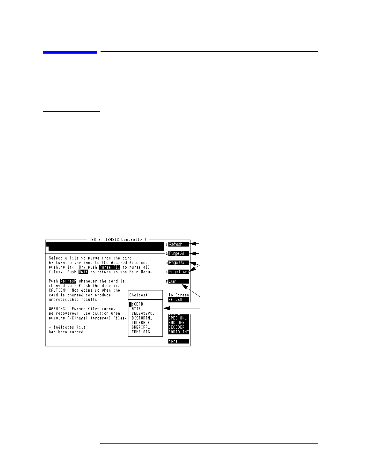
Save/Recall Register Utility (SAVRCL)
Purge Files from the Memory Card
Purge Files from the Memory Card
This function purges (deletes) any type of file from a memory card. You
can remove a single file or all files from the memory card. This
operation is helpful when you want to free up memory space by deleting
unnecessary files.
CAUTION
This function removes any type of file, including any procedure files you
may have saved. Procedure files can be identified by the lower-case “p”
preceding the file for the HP 8920A, 21A, or followed by “.prc” for the
HP 8920B.
Use the following procedure to purge files from a memory card:
1. Load and run the SAVRCL procedure (see page 18).
2. Insert the memory card containing the file(s) you want to purge.
3. Press the
k2 key, or position the cursor in front of the choice labeled
“k2: Purge Files from Memory Card” and then press the knob.
The screen shown in Figure 7-1 is displayed.
Figure 7-1 Purging Files From a Memory Card
Refresh the list of files.
Save all registers to the memory card.
Use the Page Up and Page Down
functions, or turn the knob, to view
all registers on the memory card
when there are more than seven.
Return to the previous screen.
This is the list of all save/recall
registers found on the inserted
memory card. A maximum of
seven files are shown at a time.
4. Use the knob to position the cursor in front of the file you want to
purge, then press the knob to purge the file. You can also press
k2 (Purge All) to delete all files on the card.
An asterisk (*) appears next to files that have been deleted. To view
the current contents, press
5. Press
88 Chapter 7
k5 (Quit) when you are finished purging files.
k1 (Refresh).
S:\HP11807A\OPT100\MANUAL\SAVRCL.fm
Page 89

Save/Recall Register Utility (SAVRCL)
Saving Registers to a Memory Card
Saving Registers to a Memory Card
Saving save/recall registers to a formatted memory card provides a way
to copy registers to other test sets. (See page 92 for information on
formatting the card.) It also allows you to restore the registers in a test
set that has had a firmware upgrade or has had its memory assembly
replaced. It may also be helpful when you need to run a program that
uses most of the test set’s RAM memory, requiring you to remove the
save/recall registers that occupy memory space in the test set.
Saving a register to a memory card does not remove the original
register from the test set it is copied from.
CAUTION
The test lets you save registers with names of up to nine characters in
length. However, memory card file names can only be seven characters
long. When copying registers with names of more than seven characters
to a memory card, the test set shortens the name to seven characters by
cutting off the last characters. When saving registers in the test set, you
should try to use names of seven characters or less.
Also, any register names that were saved in the test set using lower
case letters (through programs) will be copied to the memory card using
all upper case letters.
Although the test set lets you save registers using the underscore
character (_), do not save registers using the underscore for the first
character (such as _cell23). The SAVRCL program creates its own
unique file for each saved register using the underscore at the start of
the name to identify instrument settings. Creating your own files using
the underscore at the start could prevent the register from being
successfully copied.
Use the following procedure to save registers to a memory card:
1. Load and run the SAVRCL procedure (see page 18).
2. Insert a formatted SRAM memory card into the test set.
Save/Rec all REgister Utility
Chapter 7
3. Press the
k3 key, or position the cursor in front of the choice labeled
“k3: Save Registers to Memory Card” and then press the knob.
The screen shown in Figure 7-2 on page 90 is displayed.
Chapter 7 89
S:\HP11807A\OPT100\MANUAL\SAVRCL.fm
Page 90

Save/Recall Register Utility (SAVRCL)
Saving Registers to a Memory Card
Figure 7-2 Saving Registers to a Memory Card
Refresh the list of files.
Save all registers to the memory card.
Use the Page Up and Page Down
functions, or turn the knob, to view
all registers on the memory card
when there are more than seven.
Return to the previous screen.
This is the list of all save/recall
registers found on the inserted
memory card. A maximum of
seven files are shown at a time.
4. Use the knob to position the cursor in front of the register you want
to save, then press the knob to save it. You can also select
k2 (Save All) to save all registers in the test set to the card.
5. Press
k5 (Quit) to return to the previous menu.
90 Chapter 7
S:\HP11807A\OPT100\MANUAL\SAVRCL.fm
Page 91

Save/Recall Register Utility (SAVRCL)
Restoring (Copying) Registers to the Test Set
Restoring (Copying) Registers to the Test Set
This function copies save/recall registers from a memory card into the
RAM of a test set. This lets you copy registers saved from one test set to
another test set, or restore registers on a test set where the registers
had been purged (such as after a firmware upgrade).
The original register on the memory card is not affected.
Use the following procedure to copy registers from a memory card into a
test set:
1. Load and run the SAVRCL procedure (see page 18).
2. Insert the memory card containing the save/recall registers into the
test set.
3. Press the
k4 key, or position the cursor in front of the choice labeled
“k4: Restore Registers to Test Set” and then press the knob.
The screen shown in Figure 7-3 is displayed.
Figure 7-3 Copying Registers From a Memory Card to the Test Set
Refresh the list of files.
Save all registers to the test set.
Use the Page Up and Page Down
functions, or turn the knob, to view
additional registers on the memory
card.
Return to the previous screen.
This is the list of all save/recall
registers found on the inserted
memory card. A maximum of
seven files are shown at a time.
Save/Rec all REgister Utility
Chapter 7
Chapter 7 91
S:\HP11807A\OPT100\MANUAL\SAVRCL.fm
Page 92

Save/Recall Register Utility (SAVRCL)
Formatting a Memory Card
Formatting a Memory Card
A memory card must be formatted before data can be stored on it; much
like a personal computer’s hard or floppy disk. See “Memory Cards” on
page 110.
CAUTION
Formatting the memory card erases any data stored on the card.
Use the following procedure to format a memory card:
1. Load and run the SAVRCL procedure (see page 18).
2. Verify that the write protect switch on the memory card you want to
format is not set to “SAFE” or “WP”.
3. Insert the memory card into the test set.
4. Select “--> Format Memory Card” and then press the knob. The
screen shown in Figure 7-4 is displayed.
Figure 7-4 Formatting a Memory Card
Format the memory card.
Return to the previous screen.
5. Press
k1 (Proceed) to format the memory card. Do not interrupt the
test set while the prompt “FORMATTING” is displayed.
6. Press
92 Chapter 7
k1 (Proceed) to return to the previous menu.
S:\HP11807A\OPT100\MANUAL\SAVRCL.fm
Page 93

8 Reference (Alphabetical)
Re fer en ce (Alph ab etical )
Chapter 8
S:\HP11807A\OPT100\MANUAL\referenc.fm
93
Page 94

Reference (Alphabetical)
This chapter provides detailed descriptions of the features and
functions of the HP 11807A,E software. Topics are arranged
alphabetically on the pages indicated in the following list:
• “Conventions Used” on page 95
• “Copying Files” on page 96
• “Data Collection (Saving and Retrieving Test Results)” on page 97
• “HP-IB Control Annunciators” on page 109
• “Memory Cards” on page 110
• “Parameters” on page 115
• “Pass/Fail Limits (specifications)” on page 116
• “Pausing or Stopping a TEST” on page 117
• “Printing” on page 118
• “Procedures” on page 125
• “RAM” on page 131
• “Saving Tests Results” on page 134
• “Test Execution Conditions” on page 135
• “USER Keys” on page 137
94 Chapter 8
S:\HP11807A\OPT100\MANUAL\referenc.fm
Page 95

Reference (Alphabetical)
Conventions Used
Conventions Used
Special presentations of text in this manual reflect the appearance of
the item being referred to.
Examples of these special presentations are:
TESTS
A key on the test set.
Procedure:
Characters displayed on the CRT display.
k1 (Run Test)
A USER key, in the key column next to the CRT. Run Test is displayed
on the CRT.
0.000000
A field on the CRT where entries can be made.
Titles of documentation are printed in italics.
The term “test set” refers to the HP 8920A,B,D, 8921A,D.
In the steps in this manual the following words are used to describe
cursor and entry actions:
• select refers to pressing the knob after positioning the cursor in
front of the appropriate field (inverse video area).
• choose means to position the cursor in front of an item in the
Choices: or To Screen menu in the lower right corner of the CRT
display, and then press the knob.
• enter means to use the numeric keypad, and the ENTER key or
measurement units keys to make entries to fields. In some
procedures, enter is used to describe the action of entering characters
into a field.
Re fer en ce (Alph ab etical )
Chapter 8
Chapter 8 95
S:\HP11807A\OPT100\MANUAL\referenc.fm
Page 96

Reference (Alphabetical)
Copying Files
Copying Files
You can copy a file from a memory card to an SRAM memory card by
loading the program from the memory card into the test set, inserting
an initialized SRAM memory card, and then using the IBASIC SAVE
command. Enter the following:
SAVE “MY_TEST:INTERNAL”
You can list the names of the files stored in a memory card catalog by
using the IBASIC CAT command. To display a list of file names on a
memory card, enter the following:
CAT “:INTERNAL” or CAT
The mass storage powers-up to memory card as a default. If you did not
change this setting, then ”:INTERNAL” is optional. If you are entering
many characters into the IBASIC command line, you may want to
connect a terminal to the test set. See “Serial Connection” on page 119.
You will also want to use a terminal if you have many files to list
because file names displayed with the CAT IBASIC command scroll past
the top of the test set’s CRT display and cannot be scrolled down.
IBASIC is used when writing your own programs, and is not explained
in this manual. See “What is Not Explained in This Manual” on page 21
for a listing of programming manuals.
See also: “Data Collection (Saving and Retrieving Test Results)” on
page 97, “Memory Cards” on page 110 and “Formatting a Memory
Card” on page 92.
96 Chapter 8
S:\HP11807A\OPT100\MANUAL\referenc.fm
Page 97

Reference (Alphabetical)
Data Collection (Saving and Retrieving Test Results)
Data Collection (Saving and Retrieving Test
Results)
The software has the capability to save test results to an SRAM
memory card or to a PC.
NOTE
To configure
External Devices
entries:
The HP 11807A,E Option 100 software uses this function only with the
RFTOOLS library.
Collection to a Memory Card
You will have to make entries into the External Devices (Edit Config)
screen to describe the type of data collection you are using.
1. Press the
2. Select External Devices from the SET UP TEST SET list (or Edit
Cnfg from the Test Function field).
3. Position the cursor to the Calling Name field and select it.
4. Select DATA COLLECTION from the Choices menu to enter it into the
Calling Name next to Inst# 1. The entry will look like:
1 DATA COLLECTION
5. Position cursor to the Addr field and select it.
6. Using the DATA keypad, enter a number into Addr, depending on
the type of storage media you will be using (press ENTER when
complete):
If you are using a memory card, enter 1 into the Addr:
TESTS key.
Re fer en ce (Alph ab etical )
Chapter 8
1 DATA COLLECTION 1
Calling names can be entered in any order.
The test software supports data storage on Logical Interchange Format
(LIF) and Disk Operating System (DOS) disk formats. Storage can be to
any of the following file types:
• ASCII files under LIF
• BDAT files under LIF
• HP-UX files under LIF
• DOS files under DOS
Chapter 8 97
S:\HP11807A\OPT100\MANUAL\referenc.fm
Page 98

Reference (Alphabetical)
Data Collection (Saving and Retrieving Test Results)
You will be specifying the file type with the entry you make into the
Options field immediately below DATA COLLECTION. If no file type is
entered, and the disk format is LIF, the software will select an HP-UX
file type. If no file type is entered, and the disk format is DOS, the
software will select a DOS file type. For example, if you are using a
DOS file and you are not using an extension on the file name, the entry
on this screen will look like:
1 DATA COLLECTION 1
If you are using an ASCII, BDAT or HP-UX file, you can specify the
number of records allocated to the file. The DOS file is automatically
updated as data is stored, so record allocation is not required. If you are
using HP-UX files, you will have to enter REC= to establish a usable
number of records. REC=20480 sets the size to be the same as the
default number of 256 byte records used for ASCII files (80 x 256). You
can enter the REC= after the file type. For example, to use an ASCII file
with 200 records of 256 bytes each, you will enter ASCII REC=200 into
the Options field.
NOTE
For some software revisions, REC= and ASCII REC= will appear in the
Choices menu. In this case, you may select REC= or ASCII REC=, enter
the number of records using the DATA keypad, then select Done,
instead of typing in each character individually.
The display will appear as follows:
1 DATA C 1
ASCII REC=200
The default number of records, used when no REC= entry is made, is 80.
Items in the Options field can be separated by a comma or a space.
98 Chapter 8
S:\HP11807A\OPT100\MANUAL\referenc.fm
Page 99

Reference (Alphabetical)
Data Collection (Saving and Retrieving Test Results)
See “Initializing an SRAM Memory Card” on page 113 if using a new
memory card. The file types under LIF can be used by the test set’s
IBASIC controller and some HP workstations.
Table 8-1 Data Collection (Saving/Retrieving Tests) Configuration Summary
Inst# Calling Name
Model Addr Description
Options
1 DATA Collection don’t care 1 To memory card
Options:
1
File types of
ASCII,
or BDAT,
or (EXT),
2
don’t care LIF format
DOS file type
Number of
Records
or blank,
REC=xxxxx,
(number of
records)
1 DATA Collection don’t care 9 Serial to external
computer (laptop)
1. These options apply to memory card data collection. They do not
apply when collecting data with Addr=9
2. A DOS file name extension. For example, the file name may be
CELL1.EXT.
Re fer en ce (Alph ab etical )
Chapter 8
Chapter 8 99
S:\HP11807A\OPT100\MANUAL\referenc.fm
Page 100

Reference (Alphabetical)
Data Collection (Saving and Retrieving Test Results)
Retrieving Data from a Memory Card
To retrieve the test results after they have been saved on an SRAM
memory card, see the “Transfer Stored Data” on page 56.
Collection to a PC
Test results can be output through the serial port. A variety of devices
can receive the data. An HP Palmtop computer, PC, laptop, or terminal
can be used. A terminal emulator can log the test results to a file.
Examples of terminal emulator programs are HP AdvanceLink and
ProComm, a product of DataStorm Technologies, Inc.
For example: Configuring an IBM-Compatible PC with HP
AdvanceLink for DOS
1. Load and run HP AdvanceLink on your PC.
2. Use the following tables to set the Global Configuration, Terminal
Configuration, and Remote Configuration settings.
Table 8-2 Global Configuration Settings
FIELD SETTING
Keyboard USASCII
Personality HP
Language English
Terminal Mode Alphanumeric
Remote to enter PC’s serial port #
Printer I/F None
Memory Size 32K
Plotter I/F None
HP Mode Yes
Video Type
Select your display type
Forms Path Enter path if used
Screen Size
Enter the size
100 Chapter 8
S:\HP11807A\OPT100\MANUAL\referenc.fm
 Loading...