

Page 1

Agilent Technologies 8920A/B RF Communication Test Set
Agilent Technologies 8921A Cell Site Test Set
Assembly Level Repair
Firmware Version
8920A A.14.07 and above
8920B B.01.07 and above
8921A A.14.07 and above
POWER
OFF ON
MAX POWER 60 W
!
CONTINUOUS
SCREEN CONTROL
DATA FUNCTIONS
USER DATA
REF SET
k1’
INCR
k1
: 10
k2’
LO LIMIT HI LIMIT
k2
k3’
CURSOR CONTROL
k3
ASSIGN
k4
RELEASE
k5
SHIFT
CANCEL
!
ANT IN
MAX POWER 200 mW
DUPLEX OUTRF IN/OUT
Agilent Part No. 08920-90168
Printed in U. S. A.
May 2000
Rev. F
CONFIGHELPMSSG HOLD PRINT
DUPLEXTXRX PREV TESTS
METER
AVG
INCR
INCR X10
SET
PUSH TO SELECT
INSTRUMENT STATE
ADRS
SAVE
LOCAL
RECALL
789
456
123
+
ON/OFF
0
YES
Ω
NO
%
ppm
dBµV
W
AUDIO OUTSQUELCHVOLUMEMIC/ACC
MAX
!
12 v Pk
MEAS
PRESET
RESET
ENTER
dB
GHz
dBm
%
MHz
V
s
kHz
_
mV
ms
Hz
µV
MEMORY
CARD
AUDIO IN
LOHI
MAX
!
42 v Pk
1
Page 2

Copyright © 2000 Agilent Technologies
Notice Information contained in this document is subject to change without notice.
All Rights Reserved. Reproducti on, adaptation, or translati on without prior written
permission is prohibited, except as allowed under the copyright laws.
This material may be reproduced by or for the U.S. Government pursuant to the
Copyright License under the clause at DFARS 52.227-7013 (APR 1988).
Agilent Technologies
Learning Products Department
24001 E. Mission
Liberty Lake, WA 99019-9599
U.S.A.
2
S:\agilent\8920\ALR\MANUAL\front.fb
Page 3

Safety Summary The following general safety precautions must be observed during all phases of
operation of this instrument. Failure to comply with these precautions or with
specific warnings elsewhere in this manual violates safety standards of design,
manufacture, and intended use of the instrument. Agilent Technologies Inc.
assumes no liability for the custome r’s failure to comply with thes e requireme nts.
GENERAL
This product is a Safety Class 1 instrument (provided with a protective earth
terminal). The protectiv e features of this product may be impaired if it is used in a
manner not specified in the operat ion instru ctions.
All Light Emitting Diodes (L EDs) used in this product are Class 1 LEDs as per IEC
60825-1.
This product has been designed and tested in accordance with IEC Publication
1010, "Safety Requirements for Electronic Measuring Apparatus," and has been
supplied in a s afe c ondi tion. This instruction documentation cont ai ns information
and warnings which must be followed by the user to ensure safe operation and to
maintain the product in a safe condition.
ENVIRONMENTAL CONDITIONS
This instrument is intended for indoor use in an installation category II, pollution
degree 2 environment. It i s designed to opera te at a maximum relati ve humidity of
95% and at altitudes of up to 2000 meters. Re fer to the s pecificati ons tables f or the
ac mains voltage requirements and ambient operating temperature range.
V entilation Requirements: When installing the product in a cabinet, the convection
into and out of the product must not be restricted. The ambient temperature
(outside the cabin et) must be les s than t he maximum oper atin g temper atu re of t he
product by 4° C for every 100 watts dissipated in the cabinet. If the total power
dissipated in th e cabi net is great er th an 8 00 watts , then force d con vecti on must b e
used.
BEFORE APPLYING POWER
Verify that the product is set to match the available line voltage, the correct fuse is
installed, and all safety precautions are taken . Note the instrument's external
markings described under Safety Symbols.
3
Page 4

GROUND THE INSTRUMENT
T o mi nimize s hock hazard , the inst rument chas sis and c over must be connec ted to
an electrical protective earth ground. The instrument must be connected to the ac
power mains through a grounded power cable, with the ground wire firmly
connected to an electrical ground (safety ground) at the power outlet. Any
interruption of the protective (grounding) conductor or disconnection of the
protective earth terminal will caus e a potential shock haza rd that could result in
personal injury.
FUSES
Only fuses with the required rate d current, voltage, and specified type (normal
blow , time de lay, etc.) should be use d. Do not use re paired fus es or short -circuit ed
fuse holders. To do so could cause a shock or fire hazard.
DO NOT OPERATE IN AN EXPLOSIVE ATMOSPHERE
Do not operate the instrument in the presence of flammable gases or fumes.
DO NOT REMOVE THE INSTRUMENT COVER
Operating personnel mus t not remove in strument cover s. Component repl acement
and internal adjustments must be made only by qualified service personnel.
Instruments that appear damaged or defective should be made inoperative and
secured against unintended operation until they can be repaired by qualified
service personnel.
WARNING: The WARNING sign denotes a hazard. I t calls at tention to a procedure, practice, o r
the like, which, if not correctly performed or adhered to, could result in personal
injury. Do not proceed beyond a WARNING sign until the in dicated conditions are
fully understood and met.
CAUTION: The CAUTION sign denotes a hazard. It calls attention to an operating procedure, or the
like, which, if not correctly performed or adhered to, could result in damage to or
destruction of part or all of the product. Do not proceed beyond a CAUTION sign until the
indicated conditions are fully understood and met.
4
S:\agilent\8920\ALR\MANUAL\front.fb
Page 5

Safety Symbols
Caution, refer to accompanying documents
Warning, risk of electric shock
Earth (ground) terminal
Alternating current
Frame or chassis terminal
Standby (suppl y). Units with this symbol ar e not completel y disconnect ed from ac
mains when this switch is off.
T o completely disconnect the unit from ac mains, either disconnec t the power cord,
or have a qualified electrician install an external switch.
Product Markings CE - the CE mark is a registered trademark of the European Community. A CE
mark accompanied by a year indicated the year the design was proven.
CSA - the CSA mark is a re gistered trademark of the Canadian Standards
Association.
CERTIFICATION Agilent Tech nol ogi es certifies that this product met it s publ is hed sp ec if ic ations at
the time of shipment fr om the fac tory . Agilent Technologies further cer tifies that it s
calibration measurements are traceable to the United States National Institute of
Standards and Technology, to the extent allowed by the Institute’s calibration
facility, and to the calibration facilities of other International Standards
Organization members
5
Page 6

Agilent Technologies 08920 RF Communications Test Set
Duration of
Warranty: 1 year
1. Agilent Technologies warrants Agilent Technologies hardware, accessories and
supplies against defects in materials and workmanship for the period specified above.
If Agilent Technologies receives notice of such defects during the warranty period,
Agilent Technologies will, at its option, either repair or replace products which prove
to be defective. Replacement products may be either new or like-new.
2 Agilent Technologies warrants that Agilent Technologies software will not fail to exe-
cute its programming instructions, for the period specified above, due to defects in material and workmanship when properly installed and used. If Agilent Technologies
receives notice of such defects during the warranty period, Agilent Technologies will
replace software media which does not execute its programming instructions due to
such defects.
3. Agilent Technologies does not warrant that the operation of Agilent Technologies
products will be uninterrupted or error free. If Agilent Technologies is unable, within
a reasonable time, to repair or replace any product to a condition as warranted,
customer will be entitled to a refund of the purchase price upon prompt return of the
product.
4 Agilent Technologies products may contain remanufactured par ts equivalent to new in
performance or may have been subject to incidental use.
5. The warranty period begins on the date of delivery or on the date of installation if
installed by Agilent Technologies. If customer schedules or delays Agilent
Technologies installation more than 30 days after delivery, warranty begins on the 31st
day from delivery.
6 Warranty does not apply to defects resulting from (a) improper or in adequate mainte-
nance or calibration, (b) software, interfacing, parts or supplies not supplied by Agilent
Technologies, (c) unauthorized modification or misuse, (d) operation outside of the
published environmental specifications for the product, or (e) improper site preparation
or maintenance.
7 TO THE EXTENT ALLOWED BY LOCAL LAW, THE ABOVE WARRANTIES
ARE EXCLUSIVE AND NO OTHER WARRANTYOR CONDITION, WHETHER
WRITTEN OR ORAL IS EXPRESSED OR IMPLIED AND AGILENT TECHNOLOGIES SPECIFICALLY DISCLAIMS ANY IMPLIED WARRANTIES OR CONDITIONS OR MERCHANTABILITY, SATISFACTORY QUALITY, AND FITNESS
FOR A PARTICULAR PURPOSE.
6
S:\agilent\8920\ALR\MANUAL\front.fb
Page 7

8. Agilent Technologies will be liable for damage to tangible property per incident up to
the greater of $300,000 or the actual amount paid for the product that is the subject of
the claim, and for damages for bodily injury or death, to the extent that all such damages are determined by a court of competent jurisdiction to have been directly caused
by a defective Agilent Technologies product.
9. TO THE EXTENT ALLOWED BY LOCAL LAW, THE REMEDIES IN THIS
WARRANTY STATEMENT ARE CUSTOMER’S SOLE AND EXCLUSIVE
REMEDIES. EXCEPT AS INDICATED ABOVE, IN NO EVENT WILL AGILENT
TECHNOLOGIES OR ITS SUPPLIERS BE LIABLE FOR LOSS OF DATA OR FOR
DIRECT, SPECIAL, INCIDENTAL, CONSEQUENTIAL (INCLUDING LOST
PROFIT OR DATA), OR OTHER DAMAGE, WHETHER BASED IN CONTRACT,
TORT, OR OTHERWISE.
FOR CONSUMER TRANSACTIONS IN AUSTRALIA AND NEW ZEALAND:
THE WARRANTY TERMS CONTAINED IN THIS STATEMENT, EXCEPT TO
THE EXTENT LAWFULLY PERMITTED, DO NOT EXCLUDE RESTRICT OR
MODIFY AND ARE IN ADDITION TO THE MANDATORY STATUTORY
RIGHTS APPLICABLE TO THE SALE OF THIS PRODUCT TO YOU.
ASSISTANCE Product maintenance agreements and other customer assistance agreements are
available for Agilent Technologies products. For any assistance, contact your
nearest Agilent Technologies Sales and Service Office.
7
Page 8

DECLARA TION OF CONFORMITY
according to ISO/IEC Guide 22 and EN 45014
Manufacturer’s Name:
Agilent Technologies
Manufacturer’s Address:
24001 E. Mission Avenue
Liberty Lake, Washington 99019-9599
USA
declares that the product
Product Name:
Model Number:
Product Options:
CDMA Mobile Station Test Set
Agilent Technologies 8920
This declaration covers all options of the above
product.
conforms to the following Product specifications:
Safety: IEC 1010-1:1990+A1+A2/EN 6101 0-1:1 993
EMC: CISPR 11:1990 / EN 55011:1991 Group 1, Class A
EN 500 8 2 - 1 : 199 2
IEC 801-2:1991 - 4 kV CD, 8 kV AD
IEC 801-3:1984 - 3V/m
IEC 801-4:1988 - 0.5 kV Sig. Lines, 1 kV Power Lines
Supplementary Information:
This is a class A product. In a domestic environment this product may cause radio interference in
which case the user may be required to take adequate measures.
This product herewith complies with the requirements of the Low Voltage Directive
73/23/EEC and the EMC Directive 89/336/EEC and carries the CD-marking accordingly
Spokane, Washington USA November 20, 1995 Vince Roland/Quality Manager
8
S:\agilent\8920\ALR\MANUAL\front.fb
.
Page 9

9
Page 10

Table 1 Regional Sales Offices
United States of America:
Agilent Technologies
Test and Measurement Call Center
P.O. Box 4026
Englewood, CO 80155-4026
(tel) 1 800 452 4844
Japan:
Agilent T echnologies Japan Ltd.
Measurement Assistance Center
9-1 Takakura-Cho, Hachioji-Shi,
Tokyo 192-8510, Japan
(tel) (81) 456-56-7832
(fax) (81) 426-56-7840
Asia Pacific:
Agilent Technologies
24/F, Cityplaza One,
111 Kings Road,
Taikoo Shing, Hong Kong
Canada:
Agilent Technologies Canada Inc.
5150 Spectrum Way
Mississauga, Ontario
L4W 5G1
(tel) 1 877 894 4414
Latin America:
Agilent Technologies
Latin America Region
Headquarters
5200 Blue Lagoon Drive,
Suite #950
Miami, Florida 33126
U.S. A.
(tel) (305) 267 4245
(fax) (305) 267 4286
Europe:
Agilent Technologies
European Marketing Organization
P.O. Box 999
1180 AZ Amstelveen
The Netherlands
(tel) (3120) 547 9999
Australia/New Zealand:
Agilent Technologies
Australia Pty Ltd.
347 Burwood Highway
Forest Hill, Victoria 3131
Australia
(tel) 1 800 629 485
(fax) (61 3) 9272 0749
New Zealand
(tel) 0 800 738 378
(fax) (64 4) 802 6881
(tel) (852) 3197 7777
(fax) (852) 2506 9233
10
S:\agilent\8920\ALR\MANUAL\front.fb
Page 11

Service and
Support
Table 2
Any adjustment, maintenance, or repair of this product must be performed by
qualified personnel. Contact your customer engineer through your local Agilent
Technologies Service Center. Y ou can find a list of local service representatives on
the Web at:
http://www.agilent-tech.com/services/English/index.html
If you do not have access to the Internet, one of these cent ers can direct y ou to your
nearest representative:
United States Test and Measurement Call Center
(To ll free in US)
Europe
Canada
Japan Measurement Assistance Center
Latin America
Australia/New Zealand
Asia-Pacific
(800) 452-4844
(31 20) 547 9 900
(905) 206-4725
(81) 426 56 7832
|(81) 426 56 7840 (FAX)
(305) 267 4288 (FAX)
1 800 629 485 (Australia)
0800 738 378 (New Zealand)
(852) 2599 7777
(852) 2506 9285 (FAX)
11
Page 12

Manufacturer’s Declaration
This statement is pr ovided t o comply wi th the req uiremen ts of the Ger man Sound
Emission Directive, from 18 January 1991.
This product has a sound pressure emission (at the operator position) < 70 dB(A).
• Sound Pressure Lp < 70 dB(A).
• At Operator Position.
• Normal Operation.
• According to ISO 7779:1988/EN 27779:1991 (Type Test).
Herstellerbescheinigung
Diese Information steht im Zusammenhang mit den Anforderungen der
Maschinenlärminformationsverordnung vom 18 Januar 1991.
• Schalldruckpegel Lp < 70 dB(A).
• Am Arbeitsplatz.
• Normaler Betrieb.
• Nach ISO 7779:1988/EN 27779:1991 (Typprüfung).
12
S:\agilent\8920\ALR\MANUAL\front.fb
Page 13

Power Cables
Power Cables
Plug Type
Used in the following locations
Peru
Plug Type
Used in the following locations
Switzerland
Plug Descriptions
male/female
Straight/Straight 8120-0698 90 inches, black
Plug Descriptions
male/female
Straight/Straight
Straight/90°
Part #
(cable & plug)
Part #
(cable & p lug)
8120-2104
8120-2296
Cable Descriptions
Cable Descriptions
79 inches, gray
79 inches, gray
13
Page 14

Power Cables
Power Cables
Plug Type
Used in the following locations
Afghanistan, Albania, Algeria, Angola, Armenia,Austria, Azerbaijan, Azores
Bangladesh, Belgium, Benin, Bolivia,Boznia-Herzegovina, Bulgaria, Burkina Faso, Burma, Burundi,Bye lar us
Cameroon, Canary Islands, Central AfricanRepublic, Chad, Chile, Comoros, Congo, Croatia, Czech
Republic,Czechoslovakia
Denmark, Djibouti
East Germany, Egypt, Estonia, Ethiopia
Finland, France, French Guiana, French IndianOcean Areas
Gabon, Gaza Strip, Georgia, Germany, Gozo, Greece
Hungary
Iceland, Indonesia, Iran, Iraq, Israel, Italy,Ivory Coast
Jordan
Kazakhstan, Korea, Kyrgystan
Latvia, Lebanon, Libya, Lithuania, Luxembourg
Macedonia, Madeira Islands, Malagasy Republic,Mali, Malta, Mauritania, Miquelon, Moldova, Mongolia,
Morocco,Mozambique
Nepal, Netherlands, Netherlands Antilles, Niger,Norway
Oman
Pakistan, Pa ra guay , Po l a nd, Portugal
Rep. South Africa, Romania, Russia, Rwanda
Saudi Arabia (220V), Senegal, Slovak Republic,Slovenia, Somalia, Spain, Spanish Africa, Sri Lanka, St.
Pierre Islands
Sweden, Syria
Tajikistan, Thailand, Togo, Tunisia, Turkey,Turkmenistan
USSR, Ukraine, Uzbekistan
Western Africa, Western Sahara
Yugoslavia
Zaire
Plug Descriptions
male/female
Straight/Straight
Straight/90°
Part #
(cable & plug)
8120-1689
8120-1692
Cable Descriptions
79 inches, mint gray
79 inches, mint gray
14
S:\agilent\8920\ALR\MANUAL\front.fb
Page 15

Power Cables
Plug Type
Used in the following locations
Peru
Plug Type
Used in the following locations
Switzerland
Plug Descriptions
male/female
Straight/Straight 8120-0698 90 inches, black
Plug Descriptions
male/female
Straight/Straight
Straight/90°
Part #
(cable & plug)
Part #
(cable & p lug)
8120-2104
8120-2296
Cable Descriptions
Cable Descriptions
79 inches, gray
79 inches, gray
15
Page 16

Power Cables
125V
Plug Type
Plug Descriptions
male/female
Straight/Straight
Straight/90°
Straight/Straight
Part #
(cable & plug)
8120-1378
8120-1521
8120-1751
Used in the following locations
American Samoa
Bahamas, Barbados, Belize, Bermuda, Brazil,
Caicos, Cambodia, Canada, Cayman Islands,Columbia, Costa Rica, Cuba
Dominican Republic
Ecuador, El Salvador
French West Indies
Guam, Guatemala, Guyana
Haiti, Honduras
Jamaica
Korea
Laos, Leeward and Windward Is., Liberia
Mexico, Midway Islands
Nicaragua
Other Pacific Islands
Panama, Philippines, Puerto Rico
Saudi Arabia (115V,127V), Suriname
Taiwan, Tobago, Trinidad, Trust Territories ofPacific Islands
Turks Island
United States
Venezuela, Vietnam, Virgin Islands of the US
Wake Island
Cable Descriptions
90 inches, jade gray
90 inches, jade gray
90 inches, jade gray
16
S:\agilent\8920\ALR\MANUAL\front.fb
Page 17

Power Cables
JIS C 8303, 100 V
Plug Type
Used in the following locations
Japan
Plug Type
Used in the following locations
Denmark
Greenland
Plug Descriptions
male/female
Straight/Straight
Straight/90°
Plug
Descriptions
male/female
90°/Straight
90°/90°
Straight/Straight
Part #
(cable & plug)
8120-4753
8120-4754
Part #
(cable & plug)
8120-2956
8120-2957
8120-3997
Cable Descriptions
90 inches, dark gray
90 inches, dark gray
Cable Descriptions
79 inches, gray
79 inches, gray
79 inches, gray
17
Page 18

Power Cables
Plug Type
Plug Descriptions
male/female
Straig ht /Straight
Straight/90°
Used in the following locations
Botswana
India
Lesotho
Malawi
South-West Africa (Namibia), Swaziland
Zambia, Zimbabwe
Plug Type
Plug Descriptions
male/female
Straight/Straight
Straight/Straight
Straight/90°
Straight/90°
Part #
(cable & plug)
8120-4211
8120-4600
Part #
(cable & plug)
8120-1860
8120-1575
8120-2191
8120-4379
Cable Descriptions
79 inches, mint gray
79 inches, mint gray
Cable Descriptions
60 inches, jade gray
30 inches, jade gray
60 inches, jade gray
15.5 inches, jade gray
Used in the following locations
System Cabinets
18
S:\agilent\8920\ALR\MANUAL\front.fb
Page 19

Power Cables
Plug
Plug Type (Male)
Used in the following locations
Bahrain, British Indian Ocean Terr., Brunei
Canton, Cyprus
Enderbury Island, Equatorial Guinea
Falkland Islands, French Pacific Islands
Gambia, Ghana, Gibraltar, Guinea
Hong Kong
Ireland
Kenya, Kuwait
Macao, Malaysia, Mauritius
Nigeria
Qatar
Seychelles, Sierra Leone, Singapore, SouthernAsia, Southern Pacific Islands, St. Helena, Sudan
Tanzania
Uganda, United Arab Emirates, United Kingdom
Yeman (Aden & Sana)
Descriptions
male/female
90°/Straight
90°/90°
Part # (cable&
plug)
8120-1351
8120-1703
Cable Descriptions
90 inches, mint gray
90 inches, mint gray
Plug Type
Used in the following locations
Argentina, Australia
China (People’s Republic)
New Zealand
Papua New Guinea
Uruguay
Western Samoa
19
Plug Descriptions
male/female
Straight/Straight
Straight/90°
Part #
(cable & p lug)
8120-1369
8120-0696
Cable Descriptions
79 inches, gray
80 inches, gray
Page 20

Power Cables
This instrument was constructed in as ESD (electro-static discharge) protected environment. This is
because most of the semi-conductor devices used in this instrument are susceptible to damage by
static discharge.
ATTENTION
Static Sensitive
Devices
Depending on the magnitude of the charge, device substrates can punctured or destroyed by contact
or mere proximity of a static charge. The result can caused degradation of device performance, ea rl y
failure, or immediate destruction.
These charges are generated in numerous ways such as simple contact, separation of materials, and
normal motions of persons working with static sensitive devices.
When handling or servicing equip ment containin g static sen sitive devices, adequate pr ecauti ons must
be taken to prevent device damage or destruction.
Only those who are thoroughly familiar with industry accepted techniques for handling static
sensitive devices should attempt to service circuitry with these devices.
In all instances, measures must be taken to prevent static charge build-up on work surfaces and
persons handling the devices.
20
S:\agilent\8920\ALR\MANUAL\front.fb
Page 21

Contents
1. Introduction
Conventions Used 34
Test Set Description 36
Troubleshooting 38
Repair Process 39
Calibration 40
Service Tools, Equipment and Documentation 41
Self-Support Information 42
Support Contacts 43
Hardware and Firmware Enhancements 44
2. Troubleshooting
Four Basic Steps In Troubleshooting the Test Set 47
More About Step 2 - Run the Self-Test Diagnostic 53
More About Step 3 - Run the Functional Diagnostics 55
3. Repair
Introduction 68
Downloading Calibration Data 69
Troubleshooting Aids for Assemblies 70
Disassembly and Replacement Procedures 74
A23 RF Input Assembly 77
A1 Front Panel (includes keyboard) 79
A11 Receiver Mixer 81
A10 Power Supply Regulator 83
A9 Power Supply 85
A25 Motherboard 87
Fan 89
High-Power Attenuator 91
A20 Display (CRT) 93
A7 Controller 94
A8 Memory Assembly 95
4. P reventative Maintenance
Hardware Maintenance 98
Firmware and Memory Assembly Maintenance 102
5. Calibration
Introduction 104
Performance Tests 116
RF Gen AM Distortion
Performance Test 1 121
21
Page 22

Contents
RF Gen AM Accuracy
Performance Test 2 123
RF Gen AM Flatness
Performance Test 3 125
RF Gen FM Distortion
Performance Test 4 127
RF Gen FM Accuracy
Performance Test 5 129
RF Gen FM Flatness
Performance Test 6 131
RF Gen Residual FM
Performance Test 7 133
RF Gen Duplex Output High Level Accuracy
Performance Test 8 136
RF Gen Duplex Output Low Level Accuracy
Performance Test 9 138
RF Gen RF IN/OUT Level Accuracy
Performance Test 10 141
RF Gen Harmonics Spectral Purity
Performance Test 11 143
RF Gen Spurious Spectral Purity
Performance Test 12 145
AF Gen AC Level Accuracy
Performance Test 13 147
AF Gen DC Level Accuracy
Performance Test 14 149
AF Gen Residual Distortion
Performance Test 15 151
AF Gen Frequency Accuracy
Performance Test 16 153
AF Analyzer AC Voltage Accuracy
Performance Test 17 155
AF Analyzer Residual Noise
Performance Test 18 157
AF Analyzer Distortion and SINAD Accuracy
Performance Test 19 159
AF Analyzer DC Level Accuracy
Performance Test 20 161
AF Analyzer Frequency Accuracy to 100 kHz
Performance Test 21 163
AF Analyzer Frequency Accuracy at 400 kHz
Performance Test 22 165
22
Page 23

Contents
Oscilloscope
Performance Test 23 167
RF Analyzer Level Accuracy
Performance Test 24 169
RF Analyzer AM Accuracy
Performance Test 25 174
RF Analyzer AM Distortion
Performance Test 26 177
RF Analyzer Residual AM
Performance Test 27 181
RF Analyzer FM Accuracy
Performance Test 28 183
RF Analyzer FM Distortion
Performance Test 29 186
RF Analyzer FM Bandwidth
Performance Test 30 190
RF Analyzer Residual FM
Performance Test 31 194
RF Analyzer SSB Demodulation
Performance Test 32 196
Spectrum Analyzer Image Rejection
Performance Test 33 201
6. Performance Test Records
8920A Performance Test Record 206
8920A
RF Gen AM Distortion
Performance Test 1 207
8920A
RF Gen AM Accuracy
Performance Test 2 209
8920A
RF Gen AM Flatness
Performance Test 3 211
8920A
RF Gen FM Distortion
Performance Test 4 212
8920A
RF Gen FM Accuracy
Performance Test 5 214
8920A
RF Gen FM Flatness
23
Page 24

Contents
Performance Test 6 216
8920A
RF Gen Residual FM
Performance Test 7 217
8920A
RF Gen Duplex Output High Level Accuracy
Performance Test 8 219
8920A
RF Gen Duplex Output Low Level Accuracy
Performance Test 9 221
8920A
RF Gen RF IN/OUT Level Accuracy
Performance Test 10 227
8920A
RF Gen Harmonics Spectral Purity
Performance Test 11 230
8920A
RF Gen Spurious Spectral Purity
Performance Test 12 234
8920A
AF Gen AC Level Accuracy
Performance Test 13 236
8920A
AF Gen DC Level Accuracy
Performance Test 14 238
8920A
AF Gen Residual Distortion
Performance Test 15 239
8920A
AF Gen Frequency Accuracy
Performance Test 16 241
8920A
AF Analyzer AC Voltage Accuracy
Performance Test 17 242
8920A
AF Analyzer Residual Noise
Performance Test 18 243
8920A
AF Analyzer Distortion and SINAD Accuracy
Performance Test 19 244
8920A
AF Analyzer DC Level Accuracy
24
Page 25

Contents
Performance Test 20 245
8920A
AF Analyzer Frequency Accuracy to 100 kHz
Performance Test 21 246
8920A
AF Analyzer Frequency Accuracy at 400 kHz
Performance Test 22 247
8920A
Oscilloscope
Performance Test 23 248
8920A
RF Analyzer Level Accuracy
Performance Test 24 249
8920A
RF Analyzer AM Accuracy
Performance Test 25 250
8920A
RF Analyzer AM Distortion
Performance Test 26 252
8920A
RF Analyzer Residual AM
Performance Test 27 253
8920A
RF Analyzer FM Accuracy
Performance Test 28 254
8920A
RF Analyzer FM Distortion
Performance Test 29 255
8920A
RF Analyzer FM Bandwidth
Performance Test 30 256
8920A
RF Analyzer Residual FM
Performance Test 31 257
8920A
RF Analyzer SSB Demodulation
Performance Test 32 258
8920A
Spectrum Analyzer Image Rejection
Performance Test 33 259
8920B Performance Test Record 261
8920B
25
Page 26

Contents
RF Gen AM Distortion
Performance Test 1 262
8920B
RF Gen AM Accuracy
Performance Test 2 264
8920B
RF Gen AM Flatness
Performance Test 3 266
8920B
RF Gen FM Distortion
Performance Test 4 267
8920B
RF Gen FM Accuracy
Performance Test 5 269
8920B
RF Gen FM Flatness
Performance Test 6 271
8920B
RF Gen Residual FM
Performance Test 7 272
8920B
RF Gen Duplex Output High Level Accuracy
Performance Test 8 274
8920B
RF Gen Duplex Output Low Level Accuracy
Performance Test 9 276
8920B
RF Gen RF IN/OUT Level Accuracy
Performance Test 10 281
8920B
RF Gen Harmonics Spectral Purity
Performance Test 11 283
8920B
RF Gen Spurious Spectral Purity
Performance Test 12 286
8920B
AF Gen AC Level Accuracy
Performance Test 13 288
8920B
AF Gen DC Level Accuracy
Performance Test 14 290
8920B
26
Page 27

Contents
AF Gen Residual Distortion
Performance Test 15 291
8920B
AF Gen Frequency Accuracy
Performance Test 16 293
8920B
AF Analyzer AC Voltage Accuracy
Performance Test 17 294
8920B
AF Analyzer Residual Noise
Performance Test 18 295
8920B
AF Analyzer Distortion and SINAD Accuracy
Performance Test 19 296
8920B
AF Analyzer DC Level Accuracy
Performance Test 20 297
8920B
AF Analyzer Frequency Accuracy to 100 kHz
Performance Test 21 298
8920B
AF Analyzer Frequency Accuracy at 400 kHz
Performance Test 22 299
8920B
Oscilloscope
Performance Test 23 300
8920B
RF Analyzer Level Accuracy
Performance Test 24 301
8920B
RF Analyzer AM Accuracy
Performance Test 25 302
8920B
RF Analyzer AM Distortion
Performance Test 26 304
8920B
RF Analyzer Residual AM
Performance Test 27 305
8920B
RF Analyzer FM Accuracy
Performance Test 28 306
8920B
27
Page 28

Contents
RF Analyzer FM Distortion
Performance Test 29 307
8920B
RF Analyzer FM Bandwidth
Performance Test 30 308
8920B
RF Analyzer Residual FM
Performance Test 31 309
8920B
RF Analyzer SSB Demodulation
Performance Test 32 310
8920B
Spectrum Analyzer Image Rejection
Performance Test 33 311
8921A Performance Test Record 312
8921A
RF Gen FM Distortion
Performance Test 4 313
8921A
RF Gen FM Accuracy
Performance Test 5 315
8921A
RF Gen FM Flatness
Performance Test 6 317
8921A
RF Gen Residual FM
Performance Test 7 318
8921A
RF Gen Duplex Output High Level Accuracy
Performance Test 8 320
8921A
RF Gen Duplex Output Low Level Accuracy
Performance Test 9 322
8921A
RF Gen RF IN/OUT Level Accuracy
Performance Test 10 328
8921A
RF Gen Harmonics Spectral Purity
Performance Test 11 331
8921A
RF Gen Spurious Spectral Purity
Performance Test 12 335
28
Page 29

Contents
8921A
AF Gen AC Level Accuracy
Performance Test 13 337
8921A
AF Gen DC Level Accuracy
Performance Test 14 339
8921A
AF Gen Residual Distortion
Performance Test 15 340
8921A
AF Gen Frequency Accuracy
Performance Test 16 342
8921A
AF Analyzer AC Voltage Accuracy
Performance Test 17 343
8921A
AF Analyzer Residual Noise
Performance Test 18 344
8921A
AF Analyzer Distortion and SINAD Accuracy
Performance Test 19 345
8921A
AF Analyzer DC Level Accuracy
Performance Test 20 346
8921A
AF Analyzer Frequency Accuracy to 100 kHz
Performance Test 21 347
8921A
AF Analyzer Frequency Accuracy at 400 kHz
Performance Test 22 348
8921A
Oscilloscope
Performance Test 23 349
8921A
RF Analyzer Level Accuracy
Performance Test 24 350
8921A
RF Analyzer FM Accuracy
Performance Test 28 351
8921A
RF Analyzer FM Distortion
Performance Test 29 352
29
Page 30

Contents
8921A
RF Analyzer FM Bandwidth
Performance Test 30 353
8921A
RF Analyzer Residual FM
Performance Test 31 354
8921A
RF Analyzer SSB Demodulation
Performance Test 32 355
8921A
Spectrum Analyzer Image Rejection
Performance Test 33 356
7. Specifications
8920A 361
Signal Generator Specifications 362
Audio Source Specifications 367
RF Analyzer Specifications 368
AF Analyzer Specifications 372
Oscilloscope Specifications 375
Spectrum Analyzer Specifications (Option 102) 376
Signaling (Option 004) 379
DC Current Meter (Option 103) 380
Remote Programming (Option 103) 381
Reference Oscillator Specifications 382
Save/Recall Registers 383
General Specifications 384
8920B 385
8920B Specifications 386
8921A 427
Signal Generator Specifications 428
Audio Source Specifications 431
RF Analyzer Specifications 432
AF Analyzer Specifications 434
Oscilloscope Specifications 436
Spectrum Analyzer Specifications 437
Signaling 440
DC Current Meter 441
Remote Programming 442
Save/Recall Registers 443
General Specifications 444
30
Page 31

Contents
8. Service Screen
Introduction 446
9. Block Diagrams
Introduction 452
10. Replaceable Parts
Introduction 522
Self-Support Program 523
8920A Replaceable Parts List 525
8920B Replaceable Parts List 546
8921A Replaceable Parts List 567
11. Diagnostics Descriptions
Description Of Self-Test Diagnostic 588
Description Of Audio Diagnostics (AF_DIAGS) 596
Description Of RF Diagnostics (RF_DIAGS) 631
Description Of Miscellaneous Diagnostics (MS_DIAGS) 654
31
Page 32

Contents
32
Page 33

1
Introduction
This manual tells how to service the Agilent Technologies 8920A and 8920B RF
Communications Test Sets and the 8921A Cell Site Test Set.
33
S:\agilent\8920\ALR\MANUAL\intro.fb
Page 34

Chapter 1, Introduction
Conventions Used
Conventions Used
Throughout this manual the 8920A, 8920B and 8921A will be referred to as the
T est Set u nle ss ref erence t o a spe cifi c model number i s requi red. Al so, thr oughout
this manual a Test Set with a Digital Cellular Adapter (such as an
83204A, 83205A or 83206A) attached to it will be ref er re d to as t he Test System.
34
S:\agilent\8920\ALR\MANUAL\intro.fb
Page 35

Manual Contents
Chapter 1, Introduction
Conventions Used
This manual includes:
Procedures
• Troubleshooting
• Repair
• Preventative Maintenance
• Calibration
• Performance Tests
Reference
• Specifications
• Service Screen
• Block Diagrams
• Replaceable Parts
• Diagnostic s De scriptions
• Error Messages
The Repair section inc lu des cal ibration downloading and disassembly procedure s.
Calibration includes periodic calibration and performance tests. The Block
Diagram section includes block diagrams, theory of operation, I/O signal
descriptions, and power supply voltage distribution information.
35
S:\agilent\8920\ALR\MANUAL\intro.fb
Page 36

Chapter 1, Introduction
Test Set Description
Test Set Description
The Test Set integrates twenty-two complete instruments in one box. It is designed
to meet the communication t est nee ds of bot h servi ce and man ufa cturi ng, of fe ring
the functionality needed to test analog and digital (when used with a Cellular
Adapter) communications systems such as land mobile radios and dual-mode
cellular phones. Some of the instruments in the Test Set (some may be optional)
include:
• Synthesized AM and FM signal generator
• AM and FM Modulation analyzer
• Duplex offset ge nerator
• SSB demodulator
• RF power meter
• Audio and RF frequency counter and RF frequency error meter
• AC and DC voltmeter
• Distortion, SINAD, and signal-to-noise- rat i o meters
• Two variable audio sources
• Oscilloscope
• Spectrum analyzer and tracking generator (optional in some Test Sets)
• Signaling encoder and decoder (optional in some Test Sets)
• DC current meter (optional in so me Test Sets)
36
The Test Set contains approximately twenty-five replaceable assemblies. Most
assemblies are plug-in printed-circuit boards. Several of the internal instruments
are implemented all or in part by digital techniques.
All instrument functions are internally controlled by a microprocessor, which also
interfaces with external inputs. The Test Set can be part of an externallycontrolled system or the Test Set itself can function as the controller for a system.
IBASIC is built into the Test Set.
When a Cellular Adapter is attached to the top of the Test Set to form a Test
System, the Test Set acts as an RF source and analyzer for the Cellular Adapter
which modulates and demodulates the signal according to the format of the
cellular system it simulates. The d i agnostics for testing the Cellular Adapter (th e
top box) reside in the Test Set (the bottom box, the host controller); therefore, the
Test Set must have firmware compatible with the Cellular Adapter.
S:\agilent\8920\ALR\MANUAL\intro.fb
Page 37

Chapter 1, Introduction
Test Set Description
Digital Cellular Adapter
Digital Control Assemblies
s1
,+,V
Measurement
Control I/O
Knob and Keystrokes
T est Set
Controller
DUPLEX
TX TEST
Displays
Controls
RX TEST
Screens
Sig Gen Synthesizer
Receiver
Mod Distribution
Audio Analyzer 1
Figure 1 Test Set Description
37
S:\agilent\8920\ALR\MANUAL\intro.fb
RF Assemblies AF Assemblies
Measurements
Page 38

Chapter 1, Introduction
Troubleshooting
Troubleshooting
You can repair the Test Set yourself or send it to your local Agilent Technologies
sales and service of fi ce. Before starting a repair, you should become familiar with
basic Test Set (or Test System) operation. Refer to the applicable User’s Guide.
The troubleshooting documented in this manual is centered around built-in
diagnostics. Because the diagnostic results may be ambiguous, further
interpretation and testing may be required. There are three categories of
diagnostics built into the Test Set:
• Power-up self-test diagnostics to test contr oller functioning
• Internal RF (Radio Frequency) and AF (Audio Frequency) circuits diagnostics
• Diagnostics for the Cellular Adapter (i f appro priate)
Troubleshooting hints in this manual include:
• Instructions on how to begin troubleshooting (see chapter 2, "Troubleshooting")
• Block diagrams and theory of operation (see chapter 9, "Block Diagrams")
• Detailed information about the built-in diagnostics (see chapter 11, "Diagnostics
Descriptions")
• Error message explanations (see "General Information About Error Messages" on
page 660)
Instructions for troubleshooting Cellular Adapters are found in the Cellular
Adapter’s Assembly Level Repair manual.
38
S:\agilent\8920\ALR\MANUAL\intro.fb
Page 39

Repair Process
Chapter 1, Introduction
Repair Process
Repairing the Test Set consists of:
• Identifying the faulty instrument in the case of a Test System, (see chapter 2,
"Troubleshooting" )
• Identifying the faulty assembly if the fault is in the Test Set, (see chapter 2,
"Troubleshooting")
• Ordering a replacement assembly (see chapter 10, "Replaceable Parts")
• Replacing the faulty assembly (see chapter 3, "Repair")
• Downloading calibration data (see chapter 3, "Repair")
• Perfor ming periodic calibration (see chapter 5, "Calibration")
• Verifying Test Set performance (see chapter 5, "Calibration")
39
S:\agilent\8920\ALR\MANUAL\intro.fb
Page 40

Chapter 1, Introduction
Calibration
Calibration
The Test Set periodicall y requires some maintenance to assure that it me ets its
published specifications. Periodic calibration consists of running several built-in
calibration programs. An external frequency standard and dc voltmeter are
required. There are no screwdriver-type adjustments in the Test Set.
Run the Performance Tests at least once every two years. Run the Periodic
Calibration procedures at least every two years (
see chapter 5, "Calibration").
Cellular Adapters may also require periodic calibration. See the Cellular
Adapter’s Assembly Level Repair manual for details.
Several assemblies, when replaced, require running specific periodic calibration
procedures to create calibration factors for that assembly. In other cases, the
calibration data will be included with the replacement assembly on a memory
card. Instructions that come with the replacement assembly explain how to
download the calibr ation data. ( This is not cons idered part of periodic cali bration. )
NOTE: When troubleshooting the Test Set, it is sometimes desirable to swap a known-good assembly
(from another Test Set) for a suspected-faulty assembly. If the swapped assembly requires
calibration data, most assemblies will operate well enough with the original assembly’s
calibration data to troubleshoot and run the diagnostics. However, do not expect the Test Set
to meet its specifications and note that some assemblies may appear to fail becaus e of incorrect
calibration data. For more details see "Step 4 - Verify Test Set Functioning," in chapter 2,
on page 52.
40
S:\agilent\8920\ALR\MANUAL\intro.fb
Page 41

Service Tools, Equipment and Documentation
Service Tools, Equipment and Documentation
Chapter 1, Introduction
41
S:\agilent\8920\ALR\MANUAL\intro.fb
Page 42

Chapter 1, Introduction
Service Tools, Equipment and Documentation
Tools
One or more of the foll owin g to ols may be required to acce ss a nd r emove various
internal as semblies wi thin the Test Set.
• TX-10 Torx screwdriver
• TX-15 Torx screwdriver
• Flat blade screwdriver
• 4-mm allen wrench
• 7-mm socket wrench
• 1/16-inch allen wrench
• 3/16-inch socket wrench
• 5/16-inch open -end wrenc h
42
S:\agilent\8920\ALR\MANUAL\intro.fb
Page 43

Equipment
Chapter 1, Introduction
Service Tools, Equipment and Documentation
One or more of the following pieces of test equipment may be required to service
various internal assemblies within the Test Set.
• Frequency Standard or Electronic Counter (see chapter 5, "Calibration")
• DC Voltmeter (see chapter 5, "Calibration")
• RF Assembly Extender Board: P/N 08920-60137 (see chapter 5, "Calibration")
43
S:\agilent\8920\ALR\MANUAL\intro.fb
Page 44

Chapter 1, Introduction
Service Tools, Equipment and Documentation
Documentation
This manual is part of a set consisting of the following manuals:
• User’s Guide
• Programmer’s Guide
• IBASIC Reference
• Assembly Level Repair
44
S:\agilent\8920\ALR\MANUAL\intro.fb
Page 45

Self-Support Information
For U.S. customers that wish to repair their own Test Sets, a special toll-fre e
number (1 800 827 3848) is available for hardware troubleshooting assistance.
This is a special service specifically designed for customers that repair their own
Test Sets. For a Test Set under warranty, there is no charge for troubleshooting
assistance, and repair parts covered under warranty will be sent directly to the
customer. If the Test Set is out of warranty, there will be a charge for parts.
The documentation suppli ed wi th yo ur t est set is an excellent source of reference,
applications, and service information. Please use these manuals if you are
experiencing technical problems.
If you have used the manuals and still have application questions, contact your
local Agilent Technologies Sales Representative.
Chapter 1, Introduction
Self-Support Information
Repair assistance is available from the factory by phone and e-mail. Parts
information is also avai lable from A gilent Technologies.
When calling for repair assistance, please have the following information ready:
• Instrument model number (892nX).
• Instrument Serial Number (tag located on the rear panel).
• Installed options - if any (tag located on the rear panel).
• Instrument firmware revision (displayed at the top of the screen when the Test Set is
powered up, and is also displayed on the CONFIGURE screen).
45
S:\agilent\8920\ALR\MANUAL\intro.fb
Page 46

Chapter 1, Introduction
Support Contacts
Support Contacts
Troubleshooting and application assistance is available for the Test Set from the
factory by phone and e-mail. Internal Agilent Technologies users can contact the
factory through Desk. Parts information is also available from Agilent
Technologies.
• Telephone
1 800 827 3848 (RF Comms Service Assistance, U.S. only)
1 509 921 3848 (RF Comms Service Assistance, International)
1 800 922 8920 (RF Comms Applications Assistance, U.S. only)
1 800 227 8164 (Direct Parts Ordering, U.S. only)
1 800 403 0801 (Agilent Instrument Support Center, U.S. only)
1 916 783 0804 (Service Parts Identification, U.S. & Intl.)
• Electronic mail (Internet): spokane_service@agilent.com
46
S:\agilent\8920\ALR\MANUAL\intro.fb
Page 47

Hardware and Firmware Enhancements
The hardware and firmwar e of thes e Test Sets are being enha nce d on a cont inuous
basis. Some hardware for these products can be upgraded by ordering specific
retrofit kits (r efer to t he speci fic User’s Guide for your Test Set). The firmware for
these T e st Sets ha s gone throu gh several revisio ns to improve performanc e and fix
problems. It is recommended that the firmware be upgraded to the latest revision
whenever a Test Set is repaired or a performance problem is found. This is
important if an assembly-level repair is performed because exchange assemblies,
which may be of a later revision than the one being replaced, may require a later
revision of the firmwar e to function correctly.
Chapter 1, Introduction
Hardware and Firmware Enhancements
47
S:\agilent\8920\ALR\MANUAL\intro.fb
Page 48

Chapter 1, Introduction
Hardware and Firmware Enhancements
48
S:\agilent\8920\ALR\MANUAL\intro.fb
Page 49

2
Troubleshooting
This chapter tells how to troubleshoot the Test Set to isolate a problem to the
defective assembly.
45
S:\agilent\8920\ALR\MANUAL\trouble.fb
Page 50

Chapter 2, Troubleshooting
The troubleshooting is centered around the built-in diagnostics. Because the builtin diagnost ics may be unable to pin point the assembly causing the failure, this
manual contains supplementary information in the form of detailed diagnostics
descriptions (
suggestions for further manual troubleshooting.
The Test Set may be part of a Test System, that is, it may have a Cellular Adapter
attached to it. You should disable the Cellular Adapter before troubleshooting the
Test Set. If you suspect that the Cellular Adapter is faulty, it is recommended that
you still verify the operation of the Test Set and then troubleshoot the Cellular
Adapter using its own documentation.
see chapter 11, "Diagnostics Descriptions") procedures, and
46
S:\agilent\8920\ALR\MANUAL\trouble.fb
Page 51

Four Basic Steps In Troubleshooting the Test Set
Four Basic Steps In Troubleshooting the Test Set
The following steps are rec ommende d as an ef fi cient way to troub leshoo t th e Test
Set. It is advisable to document the outcome of each of these steps before
contacting Agilent Technologies for service assistance. The four steps are
summarized as follows:
Step 1 - Disable the Cellular Adapter
T o troubleshoot the Test Set (bottom box), it is essential to isolate it from any Cellular
Adapter (top box) that may be attached.
Step 2 - Run the Self-Test Diagnostic
On power-up, the Test Set runs a Self-Test Diagnostic. Most of the Test Set’s digital
control functions are tested. The outco me o f th e test ap pears o n the C RT (if operating)
and on four LEDs under the top cover.
Chapter 2, Troubleshooting
Step 3 - Run the Functional D i agnostics
Running the Functional Diagnostics is a quick and convenient way to accu mulate a lot
of information about the operation of the Test Set.
Step 4 - Verify Test Set Functionality
Suggestions of things to try include: running the Performance Tests, running certain
periodic calibration procedures, emulating the application where the Test Set fails,
swapping assemblies, etc.
The four steps are illustrated in figure 2, "The Four Steps of Troubleshooting the
Test Set," on page 48
. Instructions for performing these steps are given in this
chapter. Explanation of the results is cross-referenced to other chapters in this
manual.
47
Page 52

Chapter 2, Troubleshooting
Four Basic Steps In Troubleshooting the Test Set
Test Set comes in
for repair.
Step 1
Step 2
Step 3
Is a
Cellular Adapter
attached?
No
Run the Self-Test
Diagnostic with cover on.
Do all
self tests
pass?
Yes
Run the Functional
Diagnostics.
Do all
Functional
Diagnostics
pass?
Yes
No
Rerun the SelfT e st Diagnostic
with the cover off.
No
Disable the
Cellular Adapter.
Is the
failure clear
cut?
Is the
failure clear
cut?
No
Yes
Yes
Replace the
faulty assembly.
Replace the faulty
assembly.
Yes
Step 4
Figure 2 The Four Steps of Troubleshooting the Test Set
48
1.Run the performance tests
(chap 4).
2.Run the periodic calibration
(chap 4).
3.If an instrument fault is suspected,
run the AF and RF functional diagnostics in a loop.
No
1.Read the block diagram theory (chap 7)
and the diagnostic descriptions (chap 9)
that pertain.
2.Test inputs and outputs of suspected
assemblies (chap 2 and 7).
3.If possible, swap suspected assem blies
with known good ones (chap 2).
S:\agilent\8920\ALR\MANUAL\trouble.fb
Page 53

Step 1 - Disable the Cellular Adapter.
If the Test Set has a Cellular Adapter attached, disable it as follows:
• Disconnect all of the rear-panel cables that connect the Test Set to the Cellular Adapter.
• Unplug the Cellular Adapter’s power cord.
• On the Test Set’s rear panel, connect a coaxial cable between the IQ RF IN and CW RF
OUT connectors.
Step 2 - Run the Self-Test Diagnostic.
If the Test Set has no Cellu lar Adapter or if the Cellular Adap ter has been
disabled, begin troubleshooting the Test Set by following these steps:
• Initiate the Self-Test Diagnostic by turning the Test Set on.
• After power-up, the top line of the Test Set’s display should show: (1) the copyright
date, (2) Agilent Technologies, and (3) the firmware revision code.
Chapter 2, Troubleshooting
Four Basic Steps In Troubleshooting the Test Set
• After power-up, the second line of the Test Set’s display should show: “
tests passed
• The Test Set should power-up to the RX TEST screen. (RX TEST is the default screen;
however, the Test Set can be altered to power-up to some other screen.)
.”
All self
If the Test Set powers up with the message “All self tests passed.”: Run
the Functional Diagnostics as described in step 3 below. Also
Step 3 - Run th e Functional Diagnostics" on page 55
If the Test Set powers up with an error condit ion:
the Self-Test Diagnostic" on page 53
, later in this chapter.
, later in this chapter.
see "More About Step 2 - Run
see "More About
49
Page 54

Chapter 2, Troubleshooting
Four Basic Steps In Troubleshooting the Test Set
Step 3 - Run the Functional Diagnostics.
The Functional Diagnost ics make a series of interna l measurement s which test the
integrity of many of the c ircuits within the Test Set. There are three Func tional
Diagnostics. The fi rst t wo (Audi o an d RF Diagnos tics ) can b e run co ntinuo usly i n
a loop after an initial setup. This is useful for trapping intermittent fa ilures. The
third diagnostic (Miscellaneous Diagnostics) requires a different setup for each
test.
The Functional Diagnostics should be able to pinpoint faults in the audio and RF
circuits to the faulty assembly. When a measurement is out of limits, the
diagnostics post a message on the screen that suggests which assembly to replace
and what the certainty is of that suggestion (low, medium, or high). Before
ordering replacement parts (especially when the probability is medium or low) or
if you have difficulty in understanding or running the Functional Diagnostics,
"More About Step 3 - Run the Functional Diagnostics" on page 55
chapter. For a cro ss reference betwee n Functional Diagnost ic and assembly tested
see chapter 3, "Repair".
see
, later in this
NOTE: The measurement limits of the Functional Diagnos tic tests are valid o nly at room temperature;
that is, 20 to 25°C or 65 to 75°F.
To run the Functional Diagnostics.
• Press the PRESET key.
• Press the TESTS key.
• Set the
• Set the
• Set
Select Procedure Location: field to ROM.
Select Procedure Filename: field to:
•
AFDIAGS2 or AF_DIAGS (to run the Audio Diagnostics),
•
RFDIAGS2 or RF_DIAGS (to run the RF Diagnostics), or
•
MSDIAGS2 or MS_DIAGS (to run the Miscellaneous Diagnostics).
SET UP TEST SET: field to Exec, then press the cursor control knob.
50
S:\agilent\8920\ALR\MANUAL\trouble.fb
Page 55

Four Basic Steps In Troubleshooting the Test Set
• Set Output Results To:
•
Crt to send the measurement information to the display only.
•
Printer to send the measurement information to both the display and to a printer.
(The Test Set and the printer must both be configured correctly.)
• Set test execution conditions:
• On
If Unit-Under-Test-Fails: (this can be altered as the test runs)
•
Continue to keep running when a failure occurs.
•
Stop to pause when a failure occurs.
• On
Test Procedure Run Mode (this can be altered as the test runs)
•
Continuous to run the tests continuously.
•
Single Step to pause after each measurement.
Chapter 2, Troubleshooting
• Select the
• Choose the test or tests you want to run by selecting
then choosing
RF Tests
• Follow the instructions on the scr een.
• As the tests run, you can alter test execution conditions by selecting:
•
•
•
•
If all Functional Diagnostics pass:
Run Test field.
Up or Down to move the pointer
Select. (It is recommended to select All Audio Tests and All
when running the Audio and RF Diagnostics for the first time.)
Loop to rerun the test continuously.
Pause to pause the running of the tests.
Stp Fail, that is, stop-on-failure to pause the tests when a failure is detected.
Sgl Step, that is, single-step to pause the test after each measurement.
Verify the Test Set’s functioning as described in step 4.
If any Functional Diag nostic fails: see "Step 3 - Run the Functional Diagnostics."
on page 50
.
51
Page 56

Chapter 2, Troubleshooting
Four Basic Steps In Troubleshooting the Test Set
Step 4 - Verify Test Set Functioning
Suggestions:
1. Run all or a selected group of the Performance Tests. See chapter 5, "Calibration"
2. Run selected Periodic Calibration procedures. See chapter 5, "Calibration".
3. If the problem occurs on a few specific screen or screen combinations, check table 3,
"The Relationship Between Screens and Hardware" on page 61.
4. Swap suspected assemblies with known-good ones. See "Swapping Known-Good
Assemblies" on page 63 .
52
S:\agilent\8920\ALR\MANUAL\trouble.fb
Page 57

More About Step 2 - Run the Self-Test Diagnostic
More About Step 2 - Run the Self-Test Diagnostic
If the Test Set powers up with the message:
”All self tests passed.”, it is still possible to have the following digital
problems:
• Intermittent failure in any digital assembly.
• A22 CRT Drive failure.
• Input or output failure on any I/O port of the A21 assembly (optio nal on some Test
Sets).
• Key failure (other than stuck keys) on the A1 Keyboard.
If all Self-Test Diagnostic passes and the fr ont-panel keys and kn ob work, you ca n
assume that the digital control as semblies wo rk.
Chapter 2, Troubleshooting
If the Test Set powers up with the message:
”One or more self-tests failed. Error code:<hexadecimal
error code>”
"Diagnostics Des criptions "
: See "Description Of Self-Test Diagnostic" in chapter 11,
Diagnostic.
If the error code is 1000 and a Cellular Adapter is present and enabled, the
Cellular Adapter may be at fault. Disable the Cell ular Adapte r and run the S elfTest Diagnostic again.
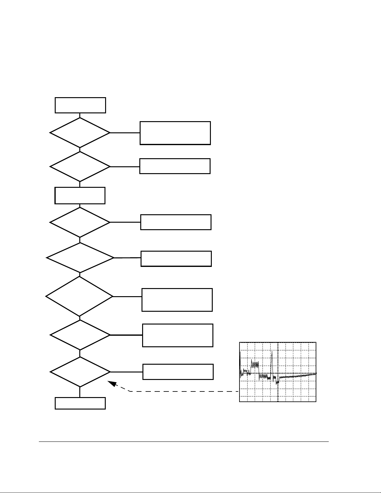
If the Test Set fails to power-up at all:
• If there is no image on the CRT, troubleshoot using figure 3, "Troubleshooting the
CRT Flowch art," on page 54.
• If there is no image on the CRT or the Test Set appears to be locked up, the Test Set
may be set to power-up to a custom procedur e (rather than th e default RX Tes t screen)
and that procedure may have errors. (This is the Autostart feature which is initiated by
setting
Autostart to On from the TESTS screen.) Correct this fault by turning the
power off, then hold down t he MEAS R ESET and Hz keys while switching t h e po we r
back on. Note that this will erase all programs and Save Settings information in RAM.
• If the Test Set does not power-up prop erly but there seems to be signs of life, there is
likely a digital control problem with one of the digital assemblies. It may be possible to
run the Self-Test Diagnostic and read the test results through the diagnostic LEDs on
the A7 Controller assembly. See "Description Of Self-Test Diagnostic" in chapter
11, "Diagnostics Descriptions" for details.
for further details on tr oubleshoo ting with the Sel f-T es t
53
Page 58
Chapter 2, Troubleshooting
More About Step 2 - Run the Self-Test Diagnostic
Power up with
cover on.
Fan runs?
Yes
Beeps?
Yes
Power up again
LEDs light?
Yes
LEDS
indicate good
power?
Yes
Power up again.
Is intensity normal
then fades out?
No
No
No
No
Check power line circuits. (Fan runs from
unregulate d 12 V.)
Check power supplies.
Controller or memory bad.
Run the self-test
diagnostics.
Yes
Press [SHIFT] [CONFIG]
[7] [ENTER].
No
At power down
does the display
flash?
No
Faulty interconnect cable
or bad high voltage powe r
supply or CRT.
Yes
Check rear-panel
CRT VIDEO OUTPUT
Video OK?
No
Faulty CRT drive.
Yes
Faulty CRT
Figure 3 Troubleshooting the CRT Flowchart
54
500 mV/div
500 µs/div
S:\agilent\8920\ALR\MANUAL\trouble.fb
Page 59

More About Step 3 - Run the Functional Diagnostics
More About Step 3 - Run the Functional Diagnostics
Memory Requirements
If the Test Set does not have 512 KBytes or more of extended RAM (optional in
some Test Sets), there is a chance that the memory required to load and run the
diagnostic program will overflow m emory. This is particula rly true of the RF
Diagnostics. If t here i s a memory o verfl ow, the error message
overflow
MSSG to review the messages.)
The Functional Diagnostics reside in the Test Set’s firmware (that is, they are
stored in ROM). When a Functional Diagnostic is selected, the program is first
loaded into t he Test Set’s RAM and then it is run. The loading and running of the
program both use RAM. This RAM is also shar ed with t he Save Set tings register s
and a few other Test Set settings.
will appear possibly followed by other error messages. (Press SHIFT
Chapter 2, Troubleshooting
ERROR 2 Memory
To run the diagnostics program when there is insufficient mem ory, RAM must
first be clea red. This will also clear the Save Settings registers, and the register
data cannot be stored elsewhere. The Test Set will also lose its TX Power Zero
setting which can easily be reacquired.
To clear RAM:
• Select the CONFIGURE screen by pressing SHIFT CONFIG.
• Move the cursor to SERVICE in the lower-right corner of the screen and press the knob.
• Move the cursor to Clear all RAM and restart at the bottom of the screen and press the
knob.
• Press the YES key.
• Re-run the diagnos tics program.
USER Keys
USER keys provide the easiest method when making test selections. The default
assignments for the USER keys on the TESTS screen match the positions of the
selection fields in the upper-right corner of the screen. The key number precedes
the field. However, key assignments are easily altered by the ASSIGN key.
If the USER keys do not match the selec tion fiel ds, either reassi gn the keys or use
the knob to place the cursor in front of the desired field and press the knob.
55
Page 60

Chapter 2, Troubleshooting
More About Step 3 - Run the Functional Diagnostics
Frequently Encountered Error Messages
Error mess ages that appear on the second lin e of the Test Set’s display frequently
occur while the Functional Diagnostics are running. The most complete and
general list of error mess ages is in the Error Messages chapter of the Test Set’s
User’s Guide and in the Test Set’s Programmer’s Guide. Some messages relating
specifically to t roubleshooting can be fo und in the Err or Messages chapter of this
manual. Some of the messages you can expect to occur while running the
Functional Diagnostics are as follows:
Functional Diagnosti cs measur ements co mmonly gen erate t he message
latch write occurred. Cycle power when done servicing.”
”Direct
The
message appears the first time the diagnostic program directly addresses a latch.
The message should be ignore d until you wish t o make a nor mal (not a diagnos tic)
measurement with the Test Set. To clear this message the Test Set should be
turned off and back on again.
The message
printer has been selected as the output destination on the
”Printer does not respond.” usually indicates tha t an GPI B
TESTS screen and that
the printer doesn’t respond. Check that the printer is on and correctly cabled and
addressed. (After a few seconds when the message times out, the output
destination is changed to CRT by the program.)
The message
selected as the o utput d est inat ion on t he
”Needs I/O to print.” indicates that a printer has been
TESTS screen but that th ere is no I/O p ort
installed in the Test Set. (After the message times out, the output destination is
changed to CRT by the program.)
Some error messages you might encounter when running the Functional
Diagnostics are the following:
”ERROR 173 IN XXXX Active/system controller req’d” (where
”XXXX” represents a line number) usually indicates that a printer has been
selected as the output destination on the TESTS screen and that the controller
Mode on the I/O CONFIGURE screen is set to Talk&Lstn instead of Control .
Change the setting and run the diagnostic again.
56
S:\agilent\8920\ALR\MANUAL\trouble.fb
Page 61

Timeouts
Chapter 2, Troubleshooting
More About Step 3 - Run the Functional Diagnostics
Certain failures may cause a frequency or voltage reading to timeout, that is, the
time required for t h e measurement will be un rea sonably long. If a ti meout o ccurs,
measurement execution will stop and an error message will be displayed.
• If frequency or voltage readings have been successfully made before the timeout, the
assembly currently being tested or a multiplexer on the A19 Measurement Assembly
may be at fault.
• If most measurements fail, the A15 Reference Assembly may be faulty in supplying
clock signals to the A19 Measurement Assembly.
• Re-run the test to see if the timeout is in termittent.
57
Page 62

Chapter 2, Troubleshooting
More About Step 3 - Run the Functional Diagnostics
The Three Functional Diagnostics
The Functional Diagnostics are contained in three independent program files.
Before ordering a replacement assembly based on the diagnostics, you should
read the descriptions of the diagnostic tests.
Descriptions"
Audio Diagnostics (AF_DIAGS or AFDIAGS2)
This program tests the audio functions of the following assemblies:
• A2 Audio Analyzer 2
• A3 Audio Analyzer 1
• A4 Modulation Distribution
• A6 Signalling Source/Analyzer (AF Generators 1 and 2 only)
• A19 Measurement (only a few selected inputs)
also see chapter 9, "Block Diagrams".
See chapter 11, "Diagnostics
After initial cabling, all tests can be run in a loop without further intervention.
This makes it easier to catch intermittent failures. The measurement limits of
these tests are valid only when operated at nominal room temperature.
When a test fails, a diagnosis is given in three parts:
• A diagnostic code.
• The name of the assembly or assemblies most likely to have failed.
• A rating (high or low) of the confidence of the diagnosis.
Before ordering an assembly based on the diagnosis, you should read the
description of the diagnostic test and details of the diagnosis based on the
diagnostic code.
"Block Diagrams"
See chapter 11, "Diagnostics Descriptions". Also see chapter 9,
.
58
S:\agilent\8920\ALR\MANUAL\trouble.fb
Page 63

Chapter 2, Troubleshooting
More About Step 3 - Run the Functional Diagnostics
RF Diagnostics (RF_DIAGS or RFDIAGS2)
This program tests the RF functions of the foll owing assem blies:
• A11 Receiver Mixer
• A13 Output
• A14 Signal Generator Synthesizer
• A15 Reference
• A16 Receiver
• A17 Receiver Synthesizer
• A18 Spectrum Analyzer (optional in some Test Sets)
• A23 Input
Some test selections require in itial ca bling befor e running th e RF Diagnost ics; but
all tests can be run in a loop without further intervention. This makes it easier to
catch intermittent failures. The measurement limits of these tests are valid only
when operated at room temperature.
When a test fails, a diagnosis is given in two parts:
• The name of the assembly or assemblies most likely to have failed.
• A rating (high, medium, or low) of the confidence of the diagnosis.
The diagnosis given by the RF Diagnostics should be verified by other means
before ordering and replacing parts. This particularly applies to the Spectrum
Analyzer, Receiver, and Receiver Mixer assemblies. Some suggestions for doing
this are as follows:
• Become familiar with the block diagram and theory of operation of the assemblies in
see chapter 9, "Block Diagrams".
• Read the description of the diagnostic test in see chapter 11, "Diagnostics
Descriptions".
• Follow the suggestion s in Further Isolating RF Failures in this chapter.
59
Page 64

Chapter 2, Troubleshooting
More About Step 3 - Run the Functional Diagnostics
Miscellaneous Diagnostics (MS_DIAGS or MSDIAGS2)
This program verifies the followin g:
• The ability of the A15 Reference to detect the presence of an external reference
connected to the rear-panel 10 MHz REF INPUT co nnecto r and wh ether it can lock to
that signal.
• The integrity of the front-panel RF IN/OUT, DUPLEX OUT and ANT IN connectors.
• The Self-Test Diagnostics, and power supply voltages. The Self-Test Diagnostic is
described in detail see "Description Of Self-Test Diagnostic" in chapter 11,
"Diagnostics Descriptions.".
Note that the Miscellaneous Diagnostics cannot be run in a loop.
Before ordering a replacement assembly based on the diagnostics, you should
read the description of the diagnostic test.
Descriptions"
. Also see chapter 9, "Block Diagrams".
See chapter 11, "Diagnostics
60
S:\agilent\8920\ALR\MANUAL\trouble.fb
Page 65

More About Step 3 - Run the Functional Diagnostics
More About Step 4 - Verify Test Set Functioning
Relating Test Set Functions To Hardware
Chapter 2, Troubleshooting
Table 3
relates the simplified block diagram to the Test Set’s control and display
screens:
Table 3 The Relationship Between Screens and Hardware
Hardware Block
Screen
RX TEST X X X X
TX TEST X X X X
DUPLEX TEST X X X X X
RF GENERATOR X X
RF ANALYZER X X
AF ANALYZER X X
OSCILLOSCOPE X X
SPECTRUM
ANALYZER
ENCODER X X
AF
Analyzer
AF
Generator
RF
Analyzer
XXX
RF
Generator
Spectrum
Analyzer
Digital
DECODER X X
RADIO
INTERFACE
CONFIGURE X
61
X
Page 66
Chapter 2, Troubleshooting
More About Step 3 - Run the Functional Diagnostics
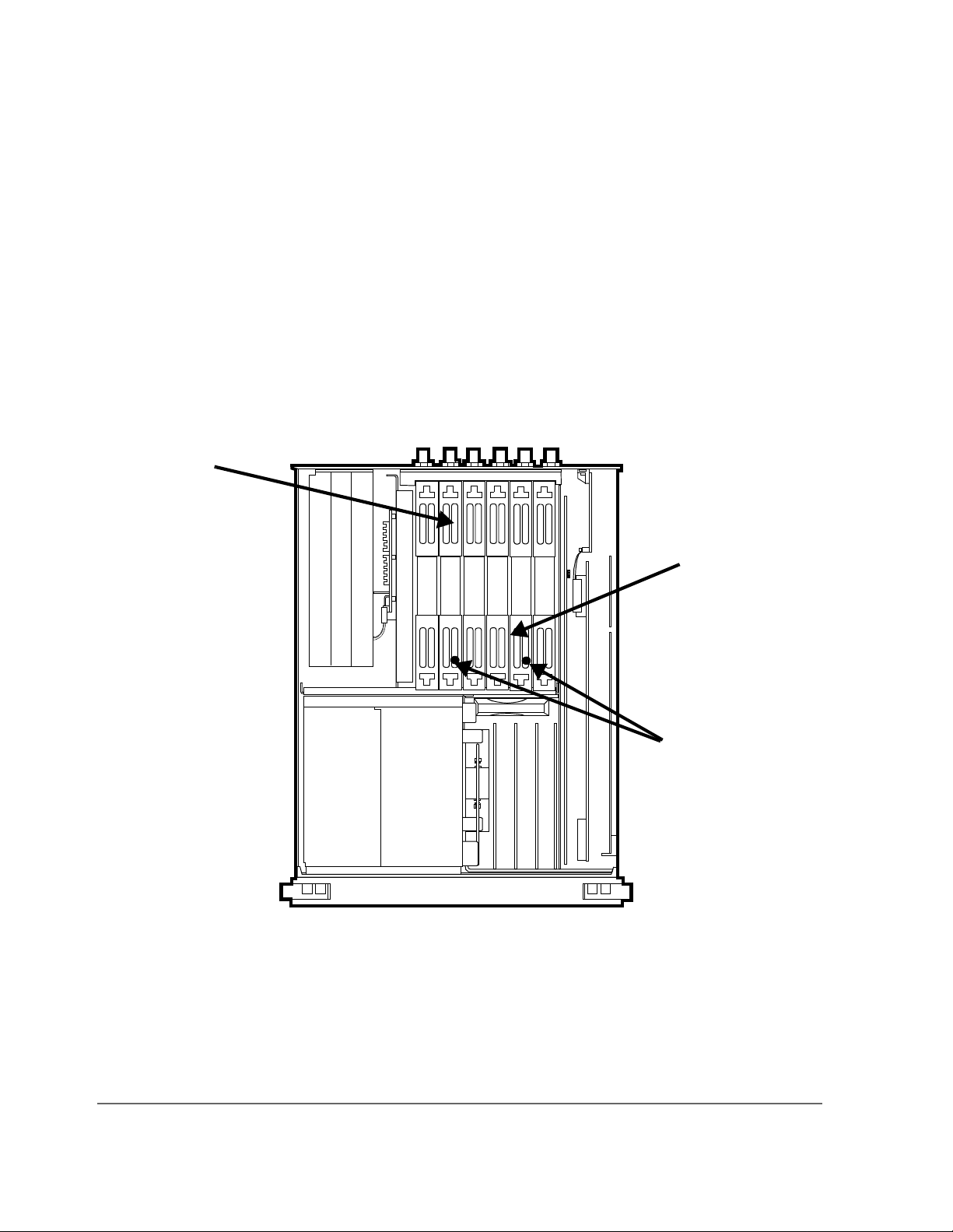
Out-of-Lock (OOL) Detectors
Two out-of-lock LEDs, one located on the A14 Signal Generator Synthesizer and
the other on the A17 Receiver Synthesizer are found within the Test Set. The
LEDs light when the phase-lock loops are not locked and therefore not
functioning properly. The location of the LED annunciators is shown in
"Location of the Out-of-Lock Annunciators," on page 62
figure 4,
.
A14 Signal
Generator
Synthesizer
A17 Receiver
Synthesizer
OOL
(Out-of-Lock)
LEDs
Figure 4 Location of the Out-of-Lock Annunciators
62
S:\agilent\8920\ALR\MANUAL\trouble.fb
Page 67

Chapter 2, Troubleshooting
More About Step 3 - Run the Functional Diagnostics
Swapping Known-Good Assemblies
Swapping a known-good assembly for a suspected faulty assembly must be
performed with good judgement. Mos t swapped a ssembli es, which us e calibr ation
data, will operate well e nough with the original assembly’s calibrati on data to
troubleshoot and to run the diagnostics. Do not expect the Test Set to meet its
specifications. Some assemblies may appear to fail bec ause of incorrect
calibration data. It is also important to keep track of which assemb lies are in th e
Test Set. If calibration data is lost, the assembly will have to b e sent back to the
factory.
Calibration data is generally stored in a socketed EEPROM on the A7 Controller.
If the Controller is replaced or swapped, the original EEPROM must be in the Test
Set’s Controller. Should the EEPROM lose its data, the entire instrume nt will
require a factory recalibration.
The assemblies that require down-loaded calibration data from a memory card
are:
• A11 Receiver Mixer
• A13 Output
• A14 Signal Generator Synthesizer
• A15 Reference
• A16 Receiver
• A17 Receiver Synthesizer
• A18 Spectrum Analyzer (optional assembly in some Test Sets)
• A19 Measurement
• A21 GPIB/RS-232/Cur rent Sense (optional assembly in some Test Sets)
• A23 Input Section
• A24 High Power Attenuator
Of these assemblies th e A23 Input Secti on is the lea st likel y to simul ate a working
assembly without its own calibration data.
The A18 Spectrum Analyzer may also pose difficulties. The Spectrum Analyzer
can be checked by measuring the Tracking Generator ported to the DUPLEX
OUT and connected to the ANT IN. Make th e che ck with the ce nter f requen cy set
to 501 MHz and a span of 1 GHz.
63
Page 68

Chapter 2, Troubleshooting
More About Step 3 - Run the Functional Diagnostics
Some assemblies require that a periodic calibration procedure be run. These are:
• A2 Audio Analyzer 2 (variable-frequency notch filter null if present)
• A3 Audio Analyzer 1 (DC offset)
• A4 Modulation Distribution (DC offset, external amplif ier gain )
• A15 Reference (time base frequency)
• A19 Measurement (voltage references)
For general troubleshooting, these assemblies can generally be swapped without
an immediate need of recalibration.
Further Isolating RF Failures
Isolating failures in the RF assemblies of the Test Set is generally more difficult
than for the rest of the instrument. One problem is that the RF Diagnostics
sometimes use the built-in RF analyzer to test the built-in RF source, and vice
versa. This is necessary to make the diagnostics self-contained, that is, they run
without external equipment.
Before using the helps in this section, run the RF Diagnostics in their entirety. (
"Step 3 - Run the Functional Diagnostics." on page 50
, earlier in this chapter.) It
will also be helpful to become familiar with:
• the RF source and analyzer block diagrams and theory of operation in chapter 9,
"Block Diagrams".
• the description of the RF and Miscellaneous Diagnostic tests in chapter 11,
"Diagnostics Descriptions".
Some general-purpose, RF test equipment will be needed:
• RF signal generator
• RF modulation analyzer or spectrum analyzer.
Isolating Input and Output Failures
If all RF diagnostic tests pass, there could still be a problem with the input and
output paths (including reverse-power and overpower protection). Run the
Miscellaneous Diagnostics test titled RF Input Output Test. A failure indicates
that the Input Section or front-panel connection is faulty.
See
64
S:\agilent\8920\ALR\MANUAL\trouble.fb
Page 69

Chapter 2, Troubleshooting
More About Step 3 - Run the Functional Diagnostics
Isolating the RF Analyzer
The RF Analyzer includes the following assemblies. (Refer to block diagrams 3
and 4 in
• A23 Input Section
• A11 Receiver First Mixer
• A16 Receiver
• A17 Receiver Synthesizer
• A18 Spectrum Analyzer (optional on some Test Sets)
chapter 9, "Block Diagrams".)
To isolate the RF Analyzer:
• On the Test Set:
• Press PRESET.
• Press TX.
• Set
Tune Mode to Manual. .
• Set
Tune Freq to 100 MHz.
• Set
Input Port to Ant.
• On the external RF signal generator:
• Set the frequency to 100 MHz CW.
• Set the amplitude to 0 dBm.
• Connect the output to the Test Set’s ANT IN connector.
• Set the RF signal generator frequency to 100, 500, and 900 MHz. For each frequency,
the TX TEST display on the Test Set should read as follows:
• TX POWER should read approximately 0.001 Ω for each frequency.
• TX FREQUENCY should read 100, 500, and 900 MHz respectively.
• If the Test Set has a Spectrum Analyzer, temporarily select SPEC ANL and note the
level and frequency of the signal’s fundamental component. (Press TX to return to
the TX TEST screen.)
Refer to block diagram BD4 in chapter 9, "Block Diagrams". The downconversion frequencies for the three input frequencies are shown in the following
table.
65
Page 70
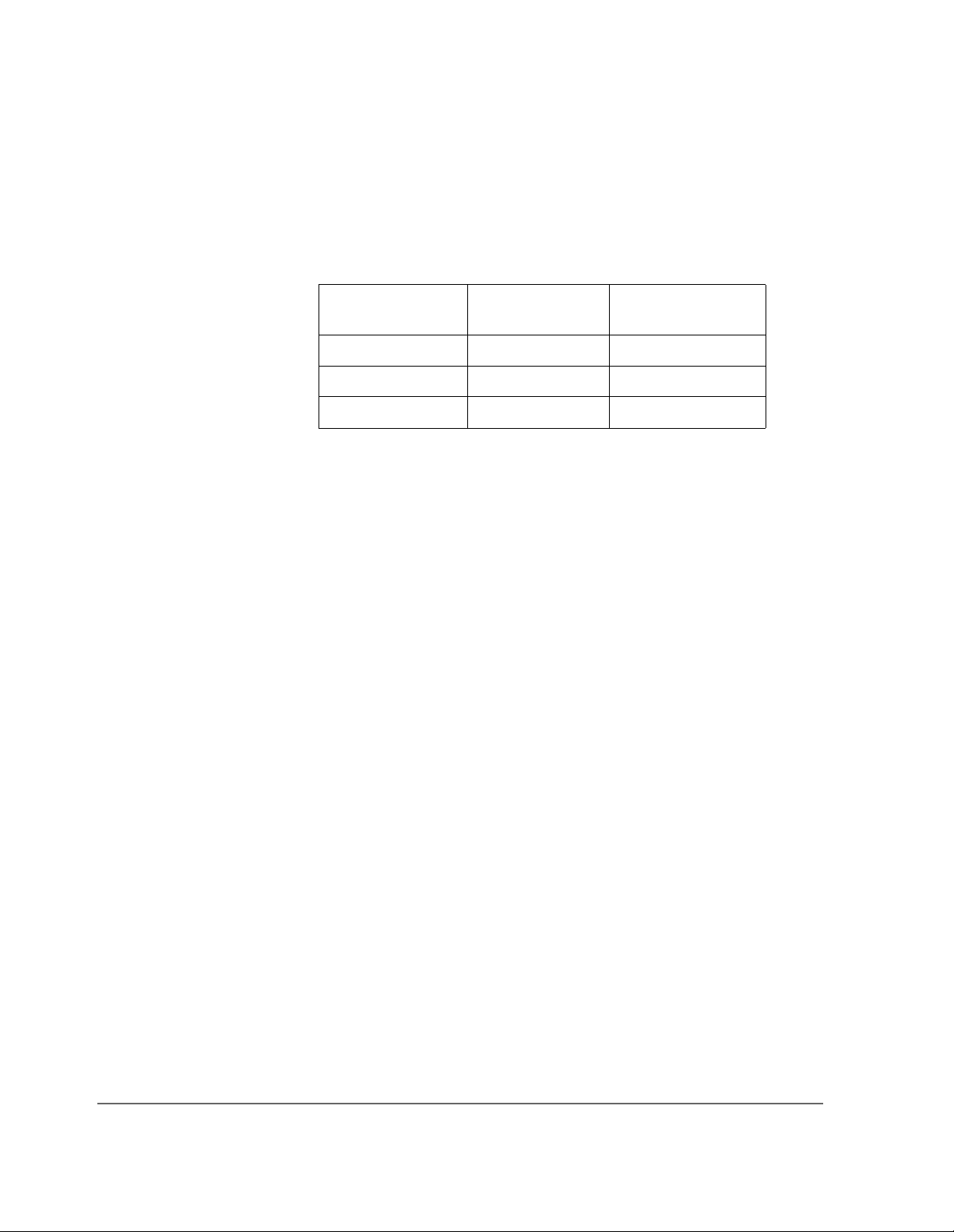
Chapter 2, Troubleshooting
More About Step 3 - Run the Functional Diagnostics
Table 4 The Relationship Between Screens and Hardware
Input Frequency
(MHz)
First LO Frequency
(MHz)
IF From First Mixer
(MHz)
100 714.3 614.3
500 614.3 114.3
900 785.7 114.3
Isolating the RF Source
The RF Source includes the following assemblies. Refer to block diagrams BD3
and BD4 in
• A15 Reference
• A14 Signal Generator Synthesizer
• A13 Output Section
• A23 Input Section
chapter 9, "Block Diagrams".
To isolate the RF Source:
• On the Test Set:
• Press PRESET.
• Press RX.
66
• Set
• Set
• Set
RF Gen Freq Mode to 600 MHz.
Amplitude to 0 dBm.
Output Port to Dupl.
• On the external RF modulation analyzer or spectrum analyzer:
• Set the tuning for a 600 MHz 0 dBm input signal.
• Connect the input to the Test Set’s DUPLEX OUT co nnecto r .
• Set the Test Set’s generator frequency to 600 , 3 00, and 150 MHz. For each frequ ency,
the external RF analyzer should read as follows:
• Power should read approximately 0.001 Ω for each frequency.
• Frequency should read 600, 300, and 150 MHz respectively.
S:\agilent\8920\ALR\MANUAL\trouble.fb
Page 71

3
Repair
67
S:\agilent\8920\ALR\MANUAL\repair.fb
Page 72

Chapter 3, Repair
Introduction
Introduction
Repair of a Test Set (or Test System) is straightforward. It involves
troubleshooting a problem to an assembly by running diagnostics and then
replacing the defective assembly. This section contains tools required, hints, and
drawings to help you perform these tasks effectively. Detailed step-b y-step
procedures are not given. A procedure for downloading calibration data is also
included in this section.
CAUTION: Perform the following procedures only at a static-safe work station. The printed circuit
assemblies in this instrument are sensitive to STATIC ELECTRICITY DAMAGE. Wear an
anti-static wrist strap that is connected to earth ground.
Recommended Torque
• Screws: Tighten until just snu g. Do not to strip threads.
• RF connectors
• Nuts holding semi-rigid coax to moth erboard: 6.0 lb-in. (68 N-cm)
SMA: 9.0 lb-in. (102 N-cm)
SMC: 6.0 lb-in. (68 N-cm)
68
S:\agilent\8920\ALR\MANUAL\repair.fb
Page 73

Downloading Calibration Data
Most assemblies in the Test Set require calibration data. To insure that the Test Set
remains calibrated after an assembly is replaced, new calibration data must be
downloaded. Depending on t he vintage and mode l number of the Test Set this may
be done with either an ‘Epson-style’ memory card (early 8920As and 8921As) or
a PCMCIA memory card (8920Bs). Newer Test Sets can, when powered-up,
automatically download calibration data directly from assemblies with on-board
calibration data.
Instructions for downloading calibration data are listed below. They are also
included with a replacement assem bly.
• Switch the Test Set’s power off. Remove the original assembly.
• Install the replacement assembly. Switch the Test Set’s power on.
• Insert the memory card (Epson-style or PCMCIA) into the Test Set.
• Press the TESTS key.
• Set the
• Set the
• Press the k1 (Run Test) key.
• Follow the instructions on the scr een.
Select Procedure Location: field to Card.
Select Procedure Filename: field to: DNLDCAL.
Chapter 3, Repair
Downloading Calibration Data
69
Page 74

Chapter 3, Repair
Troubleshooting Aids for Assemblies
Troubleshooting Aids for Assemblies
Refer to following table to determine out which Diagnostic Tests, Performance
Tests, and Periodic Self Calibration adjustments apply to an assembly you have
replaced.
Table 5 Relating Assemblies To Troubleshooting Aids
Troubleshooting with
Diagnostics (Chap 2)
Ref.
Des.
Assembly
Name
PowerUp Self
Tests
ROM
a
Performance Tests
(Chap 4)
Periodic
Self Cal
Cal Data
Needed After
Replacement ?
A1 Keyboard X MS_DIAGS:
(Self Test)
A2 Audio
Analyzer 2
AF_DIAGS:
(Audio
Analyzer 2)
A3 Audio
Analyzer 1
AF_DIAGS:
(Audio
Analyzer 1
Internal Paths)
A4 Modulation
Distribution
AF_DIAGS:
(Mod
Distribution
Internal Paths)
A5 Serial I/O X MS_DIAGS:
(Self Test)
A6 Signaling
Source
Analyzer
X AF_DIAGS:
(Audio
Frequency
Generators 1
and 2)
AF
Analyzer (AC Voltage
Accuracy)
AF Generator: (AC
Level
Accuracy)
Variable
Frequency
Notch Filter
Audio
Analyzer
Offset
AF Gen
Gain EXT
Mod Path
Gain
NO
YES, E
NO
NO
NO
NO
b
70
S:\agilent\8920\ALR\MANUAL\repair.fb
Page 75

Troubleshooting Aids for Assemblies
Table 5 Relating Assemblies To Troubleshooting Aids (Continued)
Troubleshooting with
Diagnostics (Chap 2)
Ref.
Des.
Assembly
Name
PowerUp Self
Tests
ROM
a
Performance Tests
(Chap 4)
Periodic
Self Cal
Chapter 3, Repair
Cal Data
Needed After
Replacement ?
A7 Controller X MS_DIAGS:
(Self Test)
A8 Memory X MS_DIAGS:
(Self Test)
A9 Power Supply MS_DIAGS:
(Self Test)
A10 Power Supply
Regulator
A11 Receiver
Mixer
A12 Radio Inter-
face (Opt.
MS_DIAGS:
(Self Test)
RF_DIAGS:
(Receiver)
MS_ DIAGS:
(Self Test)
020)
A13 Output RF_DIAGS:
(Output)
A14 Sig Gen
Synthesizer
RF_DIAGS:
(Signal
Generator
Synthesizer)
AF
Generat o r: (AM
Accuracy)
RF Generator:
(Harmonic and
Spurious Spe c t ra l
Purity)
NO
NO
NO
NO
YES, E
NO
YES, E
YES, E
b
, P
b
, OB
b
,OB
c
c
c
A15 Reference RF_DIAGS:
(Reference)
A16 Receiver RF_DIAGS:
(Receiver)
71
RF
Generator|
(Residual FM)
RF Analyzer: (AM
Accuracy
and FM Accuracy)
Timebase
Reference
YES, E
YES, E
b
, OB
b
, OB
c
c
Page 76

Chapter 3, Repair
Troubleshooting Aids for Assemblies
Table 5 Relating Assemblies To Troubleshooting Aids (Continued)
Troubleshooting with
Diagnostics (Chap 2)
Ref.
Des.
Assembly
Name
A17 Receiver
Synthesizer
PowerUp Self
Tests
ROM
a
RF_DIAGS:
(Receiver
Performance Tests
(Chap 4)
RF Analyzer:
(Residual FM)
Synthesizer)
A18 Spectrum
Analyzer
(Opt. 102)
RF_DIAGS:
(Spectrum
Analyzer)
Spectrum
Analyzer
Periodic
Self Cal
Cal Data
Needed After
Replacement ?
b
YES, E
YES, E
, OB
b
, P
c
c
A19 Measure-
d
ment
X MS_DIAGS:
(Self Test)
A20 CR T Drive X MS_DIAGS:
Oscilloscope Voltmeter-
Reference
YES, E
NO
b
, P
(Self Test)
A21 GPIB/RS-
232/Current
X MS_DIAGS:
(Self Test)
YES, E
b
, P
Sense (Opt.
103)
A22 CRT NO
A23 Input Section RF_DIAGS:
(Input)
A24 High Power
Attenuator
MS_DIAGS:
(RF Input/
RF Generator (Level
Accuracy)
YES, E
YES, E
b
, P
b
, P
Output)
A25 Motherboard NO
A26
Terminator
e
NO
a. Besides checking the assemblies marked X, the power-up self test checks the serial data lines which the
controller uses to send control signals to and receive status signals from the RF and AF assemblies.
b. 8920A and 8921A: E=Epson-style smart card.
c. 8920B: P=PCMCIA-style smart card, OB=EEPROM on board.
d. Measurement board checked indirectly by all diagnostics.
c
c
c
c
72
S:\agilent\8920\ALR\MANUAL\repair.fb
Page 77

Chapter 3, Repair
Troubleshooting Aids for Assemblies
e. A26 is a 50Ω termination assembly that plugs into the A18 Spectrum Analyzer position in a test set that
does not have a Spectrum Analyzer.
73
Page 78
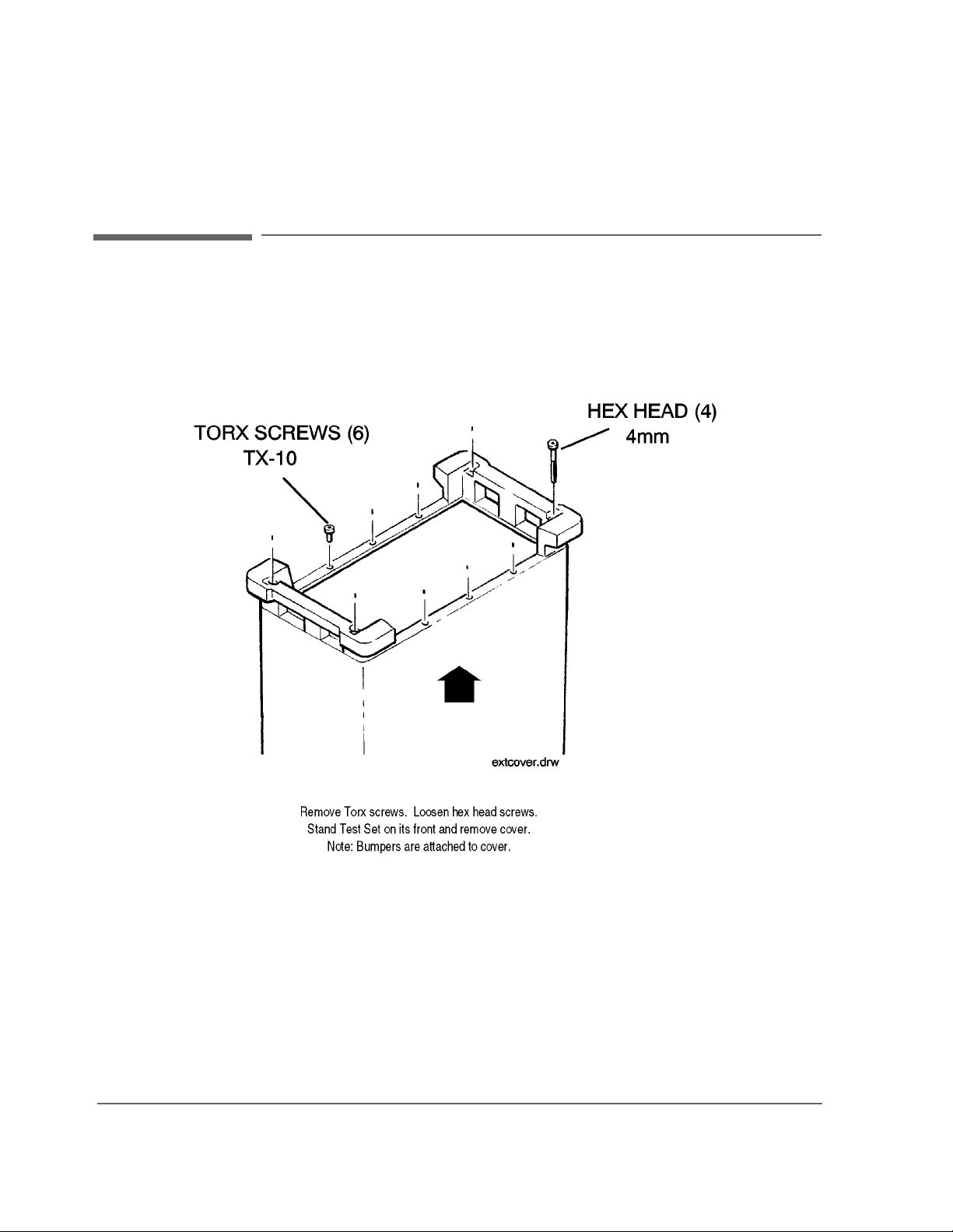
Chapter 3, Repair
Disassembly and Replacement Procedures
Disassembly and Replacement Procedures
Ordering Replacement Parts: See chapter 10, "Replaceable Parts".
Figure 5 Removing External Cover
74
S:\agilent\8920\ALR\MANUAL\repair.fb
Page 79
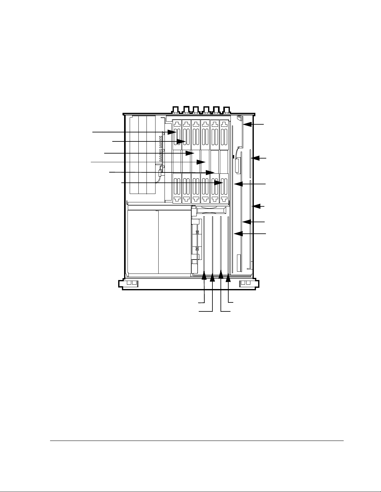
A13 Output
A14 Sig Gen Synth
Chapter 3, Repair
Disassembly and Replacement Procedures
A21 GPIB/RS-232
Centronics, Current Sense
A15 REF Synth
A16 RCVR
A17 RCVR Synth
A18 Spectrum Analyzer
A2 Audio Analyzer 2
A3 Audio Analyzer 1
A20 CRT Drive
A19 Measurement
A8 Memory
A7 Controller
A6 Signal Source Analyzer
A5 Serial I/O Controller
A4 Modulation Distribution
Figure 6 AF, Digital, and Most RF Assemblies
75
Page 80

Chapter 3, Repair
Disassembly and Replacement Procedures
GPIB
Figure 7 Internal Covers
Ordering Replacement Parts: see chapter 10, "Replaceable Parts".
76
S:\agilent\8920\ALR\MANUAL\repair.fb
Page 81

A23 RF Input Assembly
Chapter 3, Repair
A23 RF Input Assembly
Figure 8 A23 RF Input Assembly
77
Page 82

Chapter 3, Repair
A23 RF Input Assembly
Tools Required
TX-15 Torx head screwdriver
15/64 inch open end wrench
5/8 inch square drive socket
Ribbon Cable
(not shown)
Semi-Rigid Cables
(15/64” SMC Connector)
(2) TX-15 Screws
Semi-Rigid Cable
(15/64” SMC Connector)
(1) TX-15 Screw
Reassemble spacer so notched
corner fits keyboard.
(2) 5/8” Nuts
Ordering Replacement Parts: see chapter 10, "Replaceable Parts".
Calibration Data: The Test Set requires new cal data when the Input section is
replaced. A cal data memory card com es with the replacement assembly.
78
S:\agilent\8920\ALR\MANUAL\repair.fb
Page 83

A1 Front Panel (includes keyboard)
Hints: The A1 Keyboard a sse mbly is held to the fro nt panel by TX-10 screws an d
the cursor control knob. Use a 1/16-inch allen wrench to remove the knob.
Ordering Replacement Parts:
Chapter 3, Repair
A1 Front Panel (includes keyboard)
see chapter 10, "Replaceable Parts".
79
Page 84

Chapter 3, Repair
A1 Front Panel (includes keyboard)
TOOLS REQUIRED
TX-15 Torx head screwdriver
TX-10 Torx head screwdriver
1/16 inch allen wrench
5/16 inch open end wrench
5/8 inch nut driver
Ribbon Connector
(Behind front panel.)
(2) TX-15
Screws on each side.
i-Rigid Cable on back
F IN/OUT Connector
6” SMA Connector)
Microphone Connector
(under instrument)
Figure 9 Front Panel
(1) TX-10 Screw
Spacing Plates
(fit behind front panel.)
(5) 5/8” BNC Nut
Squelch and Volume Knobs
(4) 1/16” Allen screws
(2) 5/16” nuts
80
S:\agilent\8920\ALR\MANUAL\repair.fb
Page 85

A11 Receiver Mixer
Chapter 3, Repair
A11 Receiver Mixer
A11
Figure 10 A11 Receiver Mixer
Hints: To identify specific RF assemblies see figure 6, "AF, Digital, and Most RF
Assemblies," on page 75
Ordering Replacement Parts:
Calibration Data: The Test Set requires new cal data when the Receiver Mixer
assembly is replaced. A cal data memory card comes with the replacement
assembly.
Remove RF assemblies.
.
see chapter 10, "Replaceable Parts".
81
Page 86

Chapter 3, Repair
A11 Receiver Mixer
Disconnect (3) RF cables and the red wire that connects to the Regulator assembly.
(RF cables are accessed from the bottom of the Test Set.)
Tools Required
• 15/64 inch open and wrench (for RF cable connectors)
• TX-10 Torx head screwdriver
Attachment Method #1:
Pull to Release Plastic Rivet
82
Attachment Method #2:
Unscrew to Release 3mm Torx
S:\agilent\8920\ALR\MANUAL\repair.fb
Page 87

A10 Power Supply Regulator
Chapter 3, Repair
A10 Power Supply Regulator
Figure 11 A10 Power Supply Regulator
Hints: To identify specific RF assemblies see figure 6, "AF, Digital, and Most RF
Assemblies," on page 75
Ordering Replacement Parts:
Tools Required
• TX-10 Torx head screwdriver
Remove RF assemblies.
.
see chapter 10, "Replaceable Parts".
83
Page 88

Chapter 3, Repair
A10 Power Supply Regulator
A10 Power Supply
Regulator
(5) TX-10 Screws
(Short)
Power Supply
Red Wire
Molex Connector
Remove RF Assemblies
CRT
84
S:\agilent\8920\ALR\MANUAL\repair.fb
Page 89

A9 Power Supply
Chapter 3, Repair
A9 Power Supply
Figure 12 A9 Power Supply
Use the following sequence to remove the Power Supply:
1. Remove the Input assembly (see figure 8, "A23 RF Input Assembly," on page 77).
2. Pull the POWER switch shaft forward from the power supply, then pull it out back
toward the rear of the Test Set.
3. Remove the screws and molex connector.
4. Slide the power supply out from the bottom of the Test Set.
Ordering Replacement Parts: see chapter 10, "Replaceable Parts".
85
Page 90
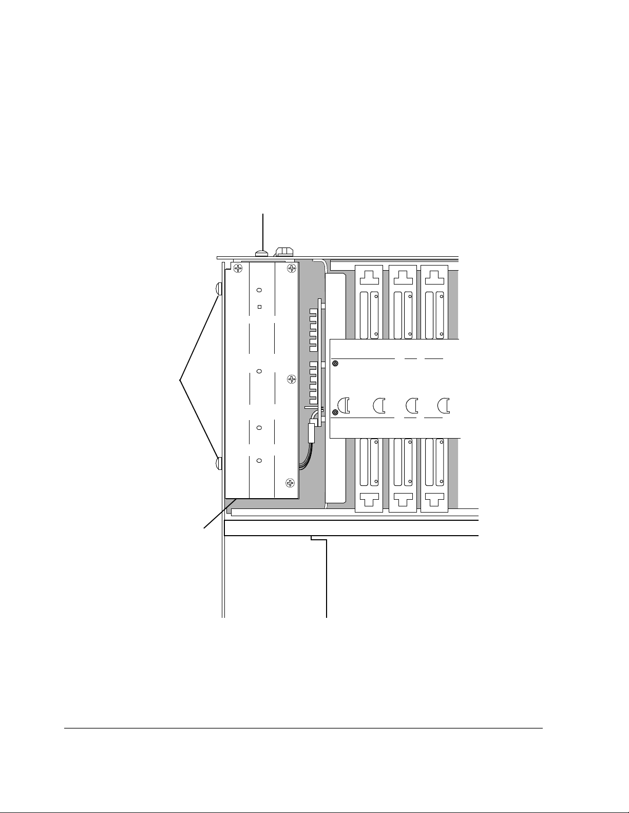
Chapter 3, Repair
A9 Power Supply
(2) TX-15 Screws
(4) TX-15 Screws
Molex Connector
(Not shown)
Figure 13 (upper left corner of test set)
86
S:\agilent\8920\ALR\MANUAL\repair.fb
Page 91

A25 Motherboard
Chapter 3, Repair
A25 Motherboard
(27) TX-10 Screws
Screws in shaded
area are longer.
(6) 5/8” BNC Nuts
(3) RF Connectors
(1) 5/16” RF conn. nut, and
(1) 15/16” SMC conn. nut (on each end,
Remove speaker
(3) TX-10 Screws
Speaker Connector
not shown), on each cable.
Center Connector
Figure 14 A25 Motherboard
87
Page 92

Chapter 3, Repair
A25 Motherboard
Use the following sequence to remove the motherboard:
1. Remove all RF, AF, and digital assemblies that plug in to the mo therb oard (see figure
6, "AF, Digital, and Most RF Assemblies," on page 75).
2. Remove the RF cables on the bottom of th e mo therbo ard. To d o th is, uns crew the n uts
and pull the cable straight out (you may have to pull hard). Be careful not to bend the
center conductor.
3. Remove the screws.
4. Remove the front panel (see figure 9, "Front Panel," on page 80).
5. Remove the rear-panel BNC nuts.
6. Lift the motherboard slightly away from the chassis and unplug the cables from the top
of the motherboard.
Ordering Replacement Parts: see chapter 10, "Replaceable Parts".
88
S:\agilent\8920\ALR\MANUAL\repair.fb
Page 93
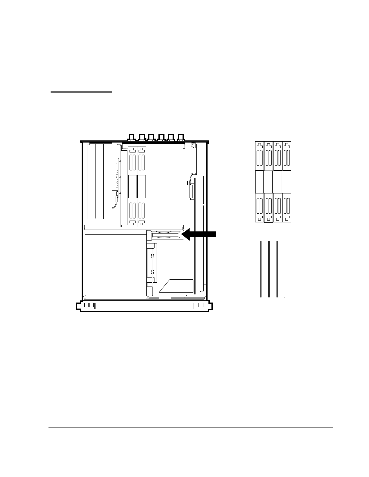
Fan
Chapter 3, Repair
Fan
Remove RF assemblies.
Figure 15 Fan
Remove AF assemblies.
Hints: To remove AF and RF Assemblies see figure 6, "AF , Digital, and Most RF
Assemblies," on page 75
Ordering Replacement Parts:
.
see chapter 10, "Replaceable Parts".
89
Page 94

Chapter 3, Repair
Fan
Disconnect fan cable
from motherboard.
Pull (4) Fasteners
Rotate fan in the
direction of
arrow.
Remove AF
assemblies.
Figure 16 (close-up view of fan)
90
S:\agilent\8920\ALR\MANUAL\repair.fb
Page 95
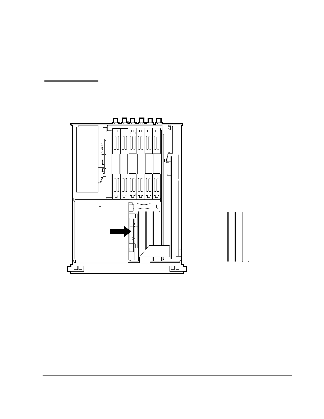
High-Power Attenuator
Chapter 3, Repair
High-Power Attenuator
Figure 17 High-Pow er Attenuator
Hints: To remove AF assemblies see figure 6, "AF, Digital, and Most RF
Assemblies," on page 75
Ordering Replacement Parts:
Calibration Data: The Test Set requires new cal data when the High-Power
Attenuator assembly is replaced. A cal data memory card comes with the
replacement assembly.
Remove AF assemblies.
.
see chapter 10, "Replaceable Parts".
91
Page 96

Chapter 3, Repair
High-Power Attenuator
(2) TX-15 Screws
(2) 5/16” SMA Connecto rs
Figure 18 (close-up view of attenuator assembly)
Push top of attenuated firmly away
from CRT.
92
S:\agilent\8920\ALR\MANUAL\repair.fb
Page 97

A20 Display (CRT)
(2) Mounting Brackets
Under CRT
(TX-15 screws)
CRT Shielding
Chapter 3, Repair
A20 Display (CRT)
CRT Cable Connector
and Socket
(2) TX-15 Screws
Display (CRT)
Figure 19 A20 Display (CRT)
Use the following sequence to remove the Display (CRT):
1. Remove the Input assembly (see figure 6, "AF, Digital, and Most RF Assemblies,"
on page 75).
2. Remove the front panel (see figure 9, "Front Panel," on page 80).
3. Remove the RF assemblies that plug into the motherboard (see figure 6, "AF, Digital,
and Most RF Assemblies," on page 75).
4. Unplug the cable.
5. Remove the bottom and side screws fr om the display.
6. Slide the display to the front.
Ordering Replacement Parts: see chapter 10, "Replaceable Parts"
93
Page 98

Chapter 3, Repair
A7 Controller
A7 Controller
Hints: To identify and access Controller assembly see figure 6, "AF, Digital, and
Most RF Assemblies," on page 75
.
Ordering Replacement Parts:
see chapter 10, "Replaceable Parts".
Table 6 Controller Switch Settings
Test Set Switch 1 Switch 2 Switch 3 Switch 4
8920A C losed Not Used Not Used Not Used
8920B Closed Open Open Not Used
8921A C losed Not Used Not Used Not Used
Switch 1: W rit e Cali bration E EPROM (Open= Disabl ed, Clos ed=Enabl ed) Swi tch
2: Smart Card (Open=PCMCIA, Closed=Epson) Switch 3: Run from Flash/OTP
(Open=Flash, Closed=OTP) Switch 4: Not Used
Open
S4 S3 S2 S1
OPEN
Boot ROM
U65 (8920B Only)
Front of Test Set
Closed
Locating Notch
Figure 20 A7 Controller
94
Cal Data EEPROM
U13 (8920A/8921A)
U20 (8920B)
S:\agilent\8920\ALR\MANUAL\repair.fb
Page 99

A8 Memory Assembly
0(025<$66(0%/<
Chapter 3, Repair
A8 Memory Assembly
8162/'(5&217$&76
21%$&.6,'(2)$66<
Figure 21 A8 Memory Assembly
Use the following procedure to remove the batteries on the Memory assembly:
1. Remove the external cover (see figure 5, "Removing External Cover," on page 74).
2. Remove the internal covers (see figure 7, "Internal Covers," on page 76).
3. Remove the A8 Memory assembly that plugs into the motherboard (see figure 6 on
page 75 for assembly removal and figure 7 on page 76 for location of side-mounte d
screws).
4. Place the assembly component-side down on a static-free surface. Unsolder, remove
and properly dispose batttery (some memory assemblies may contain two batteries).
Replace battery BT1 with part number 1420-0338.
5. Reinstall Memory assembly, internal and external covers.
Ordering Replacement Parts: see chapter 10, "Replaceable Parts"
%7
95
Page 100

Chapter 3, Repair
A8 Memory Assembly
96
S:\agilent\8920\ALR\MANUAL\repair.fb
 Loading...