


$JLOHQW7HFKQRORJLHV,QF
(0LVVLRQ
/LEHUW\/DNH:$
-XQH
ZZZDJLOHQWFRP
Dear Customer,
As of November 1, 1999, four of Hewlett-Packard’s businesses, test and measurement,
semiconductor products, health care solutions, and chemical analysis became a new company,
Agilent Technologies. Now, many of your Hewlett-Packard products and services are in the care of
Agilent Technologies.
At Agilent Technologies, we are working diligently to make this transition as smooth as possible for
you. However, as a result of this transition, the products and related documentation contained in this
shipment may be labeled with either the Hewlett-Packard name and logo, the Agilent Technologies
name and logo, or a combination of both. Information in this package may refer to Hewlett-Packard
(HP), but applies to your Agilent Technologies product. Hewlett-Packard and Agilent branded
products with the same model number are interchangeable.
Whatever logo you see, the information, products, and services come from the same reliable source.
If you have questions about Agilent Technologies products and services, please visit our website at
http://www.agilent.com.
6LQFHUHO\
5HEUDQGLQJ7HDP

HP
8901B
MODULATION
Service
SERIAL
This
manual provides complete information for in-
2314A
struments
to
2914A
For
numbers, refer
THIS
This
Government pursuant
der the clause at DFARS
with
serial-number prefixes:
and all
additional important information about serial
MANUAL"
material may be reproduced by
MAJOR
rev.
to
"INSTRUMENTS
in Section
Fourth Edition
ANALYZER
Manual
NUMBERS
changes that
12NOV92
1.
to
the Copyright License
52.227-7013
occur
COVERED
or
for the
(APR
to
your
1988).
instrument.
BY
US.
un-
Copyright@ H EWLETT-PACKARD COMPANY 1 987
EAST 24001 MISSION AVENUE, TAF C-34, SPOKANE, WASHINGTON, U.S.A. 99220
Service Manual (Volume 1, 2,
Other Documents Available:
Operation and Calibration Manual HP Part 08901-901
Basic Operation and Application Guide 08901-901
Microfiche Operation and Calibration Manual HP Part 08901-901 15
Microfiche Service Manual
3)
HP Part 08901-901 14
13
17
HP
Part 08901-901 16 Printed in USA. : April 1995
Pia
HEWLETT
PACKARD

1
Regulatory Information
(Updated
March
1999)
1
Regulatory Information (Updated March 1999)
Safety Considerations
GENERAL
This product and related documentation must be reviewed for familiarization
markings and instructions before operation.
This product
"Safety Requirements for Electronic Measuring Apparatus," and
safe condition. This instruction documentation contains information and warnings which
must be followed by the user to ensure safe operation and to maintain the product
condition.
SAFETY
A uninterruptible safety earth ground
product input wiring terminals, power cord, or supplied power cord set.
SAFETY
A
Indicates instrument damage can occur if indicated operating limits are exceeded.
A
Indicates hazardous voltages.
Indicates earth (ground) terminal
4
-
WARNING
has
been designed and tested in accordance with
EARTH
GROUND
SYMBOLS
A
WARNING
IEC
Publication
has
been supplied
must
be provided from the main power source to the
note denotes a hazard. It calls attention to a procedure,
with
practice, or the like, which, if not correctly performed or adhered to,
could result in personal injury.
sign until the indicated conditions are
Do
not proceed beyond a
fully
understood and met.
WARNING
safety
1010,
in
in
a
a
safe
CAUTION
A CAUTION note denotes a hazard.
procedure, practice, or the like, which, if not correctly performed or adhered
to, could result in damage to or destruction of part or
not proceed beyond
understood and met.
an
CAUTION note
It
calls attention to
until
the indicated conditions
an
operation
all
of the product.
are
Do
fully
2
Chapter
1

Safety Considerations for this Instrument
Regulatory
Information
(Updated
March
1999)
WARNING
This product is a Safety Class I instrument (provided with a
protective earthing ground incorporated in the power cord). The
a
mains plug shall only be inserted in
protective earth contact.
conductor inside
or
Any
outside
interruption
of
the product is likely to make the
product dangerous. Intentional interruption
Whenever
it
is
likely that the protection has been impaired, the
socket outlet provided with
of
the protective
is
prohibited.
instrument must be made inoperative and be secured against any
unintended operat ion.
If
this instrument
is
to be energized via an auto transformer
(for
voltage reduction), make sure the common terminal is connected to
the earth terminal of the power source.
If
this product
is
not used
as
specified, the protection provided by
the equipment could be impaired. This product must be used in a
normal condition (in which
No
operator serviceable parts in this product. Refer servicing
all
means for protection are intact) only.
to
qualified personnel. To prevent electrical shock, do not remove
covers.
Servicing instructions are for use by qualified personnel only.
To
avoid electrical shock, do not perform any servicing unless you are
qualified to do
so.
a
The opening of covers or removal of parts
dangerous voltages. Disconnect the product from
is
likely to expose
all
voltage sources
while it is being opened.
The power cord is connected to internal capacitors that
live for
5
seconds after disconnecting the plug from its power supply.
my
remain
For Continued protection against fire hazard, replace the line fuse(s)
only with
example, normal blow
250
V
fuse(s) or the same current rating and type (for
or
time delay). Do not use repaired fuses
or
short circuited fuseholders.
Always use the three-prong ac power cord supplied with this
product. Failure to ensure adequate earth grounding by not using
this cord may cause product damage.
This product
Pollution Degree
INDOOR
USE
is
designed
2
ONLY.
per
for
ZEC
use in Installation Category
1010
and
ZEC
664
respectively. FOR
I1
and
This product has autoranging line voltage input, be sure the supply
voltage
is
within the specified range.
Chapter
1
3

Regulatory Information (Updated March
To
prevent electrical shock, disconnect instrument
before cleaning. Use a dry cloth or one slightly dampened with water
to
clean the external case parts.
Ventilation Requirements: When installing the product in a cabinet,
the convection into and out of the product must not be restricted.
The ambient temperature (outside the cabinet) must be less than the
maximum operating temperature of the product by
watts dissipated in the cabinet.
cabinet is greater than
used.
1999)
from
Do
not attempt
If
the total power dissipated in the
800
watts, then forced convection must be
to
clean internally.
4"
C
for
mains (line)
every
100
Product
CE - the CE mark
Markings
is
a
registered trademark
of
the European Community. A CE mark
accompanied by a year indicated the year the design was proven.
CSA - the
CSA
mark
is
a registered trademark
of
the Canadian Standards Association.
4
Chapter
1

Model
8901B
Service
SAFETY CONSIDERATIONS
GENERAL
This product and related documentation must be reviewed for familiarization with safety markings and
instructions before operation.
This product is a Safety Class I instrument (provided
with a protective earth terminal).
BEFORE APPLYING
Verify that the product is set to match the available
line voltage and the correct fuse is installed.
POWER
SAFETY EARTH GROUND
An uninterruptible safety earth ground must be provided from the main power source to the product input
or
wiring terminals, power cord,
set.
supplied power cord
SAFETY SYMBOLS
Instruction manual symbol: the product will
A
is
manual (refer to Table of Contents).
be marked with this symbol when it
necessary for the user
Indicates hazardous voltages.
to
refer to the instruction
I
WARNING
Any interruption of the protective (ground-
ing) conductor (inside
or
ment)
terminal will cause a potential shock hazard
that
ing one conductor of a two conductor outlet
is not sufficient protection).
Whenever it
been impaired, the instrument must be made
inoperative and be secured against any unin-
tended operation.
If this instrument
autotransformer (for voltage reduction) make
sure the common terminal is connected to the
earth terminal of the power source.
Servicing instructions are for use by servicetrained personnel only.
electric shock,
unless qualified to do
disconnecting the protective earth
could result
is
likely that the protection has
do
or
outside the instru-
in
personal injury. (Ground-
is
to be energized via an
To
avoid dangerous
not perform any servicing
so.
Indicates earth (ground) terminal.
The WARNING sign denotes a
hazard. It calls attention to a
or
procedure, practice,
or
performed
Do
jury.
the indicated conditions are fully understood and met.
operating procedure, practice,
correctly performed
to
age
or
not proceed beyond a CAUTION sign until the indicated conditions are fully understood and met.
adhered to, could result in personal in-
not proceed beyond a WARNING sign until
destruction of part
the like, which,
The CAUTION sign denotes a haz-
It
ard.
or
calls attention to an
or
adhered to, could result in dam-
or
all of the product.
if
not correctly
the like, which,
if
not
Do
Adjustments described
formed with power supplied to the instrument
while protective covers are removed. Energy
available at many points may,
sult
in
personal injury.
Capacitors inside the instrument may still be
charged even if the instrument has been disconnected from its source of supply.
For
continued protection against fire hazard,
replace the line fuse(s) only with
of the same current rating and type (for exam-
ple, normal blow, time delay, etc.).
repaired fuses
fuseholders.
in
the manual are per-
if
contacted, re-
250V
Do
or
short circuited
fuse(s)
not use

ATTENTION
Static Sensitive
Devices
This instrument was constructed
protected environment. This
devices used
discharge.
Depending on the magnitude of
punctured
The results can cause degradation of device performance, early failure,
or
immediate destruction.
These charges are generated
separation of materials, and normal motions of persons working with
static sensitive devices.
When handling
devices, adequate precautions
or
destruction.
Only those who are thoroughly familiar with industry accepted
techniques for handling static sensitive devices should attempt to
service circuitry with these devices.
In
all instances, measures
build-up on work surfaces and persons handling the devices.
in
this instrument are susceptible to damage
or
destroyed
by
contact
or
servicing equipment containing static sensitive
in
an ESD (electro-static discharge)
is
because most of the semi-conductor
by
the
charge, device substrates can be
or
mere proximity of a static charge.
in
numerous ways such
must
be taken to prevent device damage
must
be taken to prevent static charge
as
simple contact,
static

Model 8901B
Volume 1 Table of Contents
VOLUME
Introduction
Reference Designators and Abbreviations
Replaceable
OrderingParts
Replaceable
Mechanical and Chassis
Recommended Spares List
Introduction
Firmware Change
Introduction
How
This
Safety Considerations
Before Applying Power
Safety
Service
Service Accessory Kit
Heat-Staking
Assembly Locations
Parts
Other Service Documents
Recommended Test Equipment
General Troubleshooting
Operator Errors
Operation Out
Catastrophic Failures
Schematic Symbology and Schematic Diagram Notes
Special Functions
General
Direct Control Special Functions (Prefix
Service Special Functions (Prefm
To
This
Parts
Section
List
...........................................
..............................................
................................................
Parts
List Updating
Part
(Manual
Locations and Reference Designations
............................................
to
This
Section
Summary
to
This
Section
Section is Organized
..............................................
....................................................
Tools
and Aids
Tool
and Cable Locations
..............................................
of
Specifcation
................................................
....................................................
...........................................
(23l4A
..........................................
.........................................
..........................................
.............................................
...........................................
.............................................
............................................
........................................
.........................................
............................................
...........................................
1
TABLE
SECTION 6
REPLACEABLE PARTS
....................................
Updates)
SECTION
INSTRUMENT CHANGES
to
2644A)
and
......................................
40-99)
.................................
SECTION
SERVICE
Accessories
0)
.....................
................................
OF
CONTENTS
..............................
....................
7
8
............................
............................
:
.........
6-1
6-1
6-1
6-1
6-2
6-2
6-2
7-1
7-1
8A-1
8A-1
8A-2
8A-2
8A-2
8A-3
8A-3
8A-4
8A-4
8A-5
8A-5
8A-5
8A-5
8A-5
8A-5
8A-6
8A-10
.8 B-1
8B-1
.8
B-1
.8 B-5
rev.08JUL91
~
Volume 1 Table
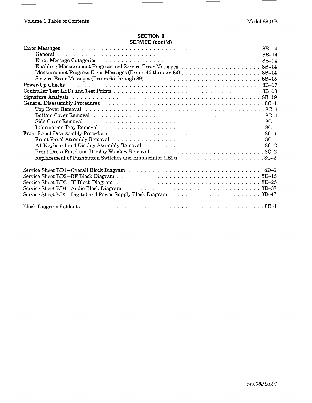
Error Messages
General
Error Message Catagories
Enabling Measurement Progress
Measurement Progress Error Messages (Errors
Service Error Messages (Errors
Power-Up Checks
Controller Test LEDs and Test Points
Signature Analysis
General Disassembly Procedures
Top Cover Removal
Bottom Cover Removal
Side Cover Removal
Wormation Tray Removal
Front Panel Disassembly Procedure
Front-Panel Assembly Removal
A1 Keyboard and Display Assembly Removal
Front
Replacement
of
Contents
.................................................
...................................................
........................................
and
65
through 89)
................................................
.....................................
...............................................
.......................................
............................................
..........................................
............................................
........................................
......................................
.....................................
Dress Panel and Display Window Removal
of
Pushbutton Switches and Annunciator LEDs
SECTION
SERVICE
Service Error Messages
40
8
(cont’d)
through 64)
.............................
.............................
...........................
Model 8901B
....................
....................
....................
8B-14
8B-14
8B-14
8B-14
8B-14
8B-15
8B-17
8B-18
8B-19
.8
C-1
.8
C-1
.8
C-1
.8
C-1
.8
C-1
.8
C-1
.8
C-1
.8
C-2
.8
C-2
.8
C-2
Service Sheet BD1-Overall Block Diagram
Service Sheet BD2-RF Block Diagram
Service Sheet BD3-IF Block Diagram
Service Sheet BD4-Audio Block Diagram
Service Sheet BD5-Digital
Block Diagram Foldouts
and
Power Supply Block Diagram
............................................
....................................
....................................
.................................
..................................
.......................
8D-1
8D-15
8D-25
8D-37
8D-47
.8
E.l
rev.08JUL91

Model
8901B
Replaceable
Parts
Section
6
REPLACEABLE PARTS
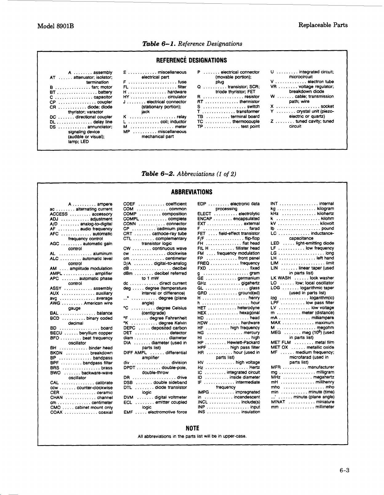
6-1.
INTRODUCTION TO THIS SECTION
This section contains information
6-2
Table
parts in the instrument. Table
manufacturer’s code numbers listed in Table
drawings
6-2.
REFERENCE DESIGNATIONS AND ABBREVIATIONS USED IN THIS MANUAL
Table
designations found in Table
designation for each part in the instrument.
particular resistor
Table
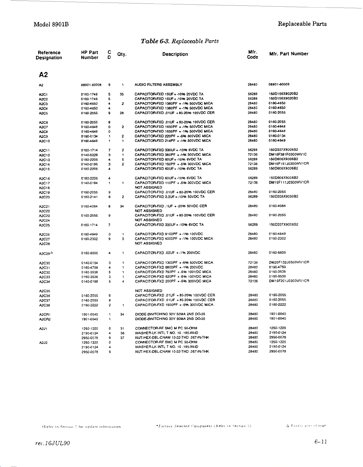
6-3.
REPLACEABLE PARTS LIST
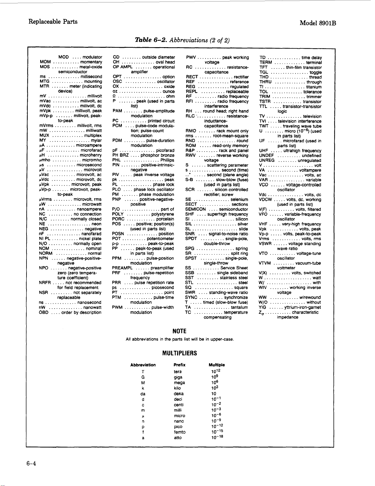
lists abbreviations that are used in the Replaceable Parts List. Table
to
aid in identifying and ordering chassis mounted parts and mechanical parts.
6-1
lists the reference designation letters for electrical parts in the instrument. The letter
6-1
R1
on assembly A17.
6-2
lists abbreviations used in the parts list and on schematics.
for
ordering parts. Table
6-4
contains the names and addresses that correspond
6-3.
Also included in this section are photographs and
are coupled with numeric designations to provide a unique reference
For
example A17R1 is the reference designation
6-1
lists reference designations, and
6-3
lists all replaceable
to
the
of
a
Table
6-3
is
a list of replaceable parts and is organized
a.
Electrical assemblies and their components with reference designations in alphanumeric order.
b. Chassis-Mounted parts with reference designations in alphanumeric order.
c. Mechanical parts with reference designations in alphanumeric order.
For your convenience, the Replaceable Parts List
6
removed from Section
Ordering
Parts.
instrument Serial Numbers.
Attached to the rear of the instrument
are the instrument serial-number prefix. The last five digits (serial-number suffix) are unique to each
instrument. When parts in the instrument are changed, the serial-number prefix of the instrument may
also
change. This means that sometimes a part will be listed more than once in the the replaceable
parts list along with a serial-number prefix
prefix on the serial plate of your instrument and order the part listed under the corresponding prefix
in the table. If no serial prefix information is listed, the part is compatible
numbers.
It is possible that some assemblies in your instrument have been updated
(through service
serial-number prefixes later than that shown on your instrument serialnumber tag. Be sure to note the board number
or
replaced when ordering parts
and collated into Section 8 with
is
a serial-number plate. The first four digits and the letter
or
range of serial-number prefixes. Find the serial-number
NOTE
or
retrofitting) to reflect changes made to instruments with
for
as
follows:
is
paginated so that each assembly listing can be
its
corresponding service information.
in
instruments of all serial
of
the assembly being repaired
your instrument.
6-
1

Replaceable Parts Model 8901B
How
to
Order
To order a part in the Replaceable Parts
List,
call
or
write the nearest Hewlett-Packard Sales Office.
Have the following information ready to speed the ordering process:
1.
The Hewlett-Packard part number with the check digit. (The check digit will ensure accurate and
timely processing of your order.)
2.
The quantity required.
3. An approved purchase order number. (Sometimes required.)
NOTE
Within
Mountain View California.
the
USA,
it
is
better to order directly from the HP Parts Center
Ask
your nearest HP ofice for information and
in
forms for the “Direct Order System”.
Replaceable Parts List Updating (Manual Updates)
A
“MANUAL UPDATES” packet is shipped with the manual, when necessary, to provide the most
current information available at the time of shipment. These packets consist of replacement and
addition pages which should be incorporated into the manual
Hewlett-Packard offers a Documentation Update Service that will provide you with further updates
If
as they become available.
you operate
recommend that you join this service immediately
or
service instruments of different serial prefixes, we strongly
to
ensure that you manual
information, refer to the Documentation Update Service reply card included in this manal,
Technical Writing Department (509) 922-4001,
to
bring
it
up
to
is
date.
kept current.
For
or
more
call:
6-4.
6-5.
or
write:
Hewlett-Packard Company
Technical Writing Department
-
24001 E. Mission
TAF C-34
Spokane, WA 99220
MECHANICAL AND CHASSIS PART LOCATIONS AND REFERENCE DESIGNATIONS
Most mechanical parts are identified in Figures 6-1 to 6-9. These figures are located at the end of
this section. Major mechanical parts have reference designations that begin with the letters MP. To
find the part number and description of a mechanical part, find the part in one of the photographs
or
drawings, and then look up the reference designation in Table 6-3. Mechanical hardware, such as
For
screws, are listed under the part which they attach.
to the rear panel are listed under
B1.
example, the screws that attach the fan (Bl)
RECOMMENDED SPARES LIST
Stocking spare parts for an instrument is often done
occurs. Hewlett-Packard has prepared a “Recommended Spares” list for this instrument. The contents
list
of the
are based on failure reports and repair data. Quantities given are for one year of parts
support. You can request a complimentary copy of the “Recommended Spares” list from your nearest
Hewlett-Packard office.
When stocking parts to support more than one instrument
instruments,
adding together stocking quantities
it
may be more economical to work from one consolidated list rather than simply
from
the individual instrument lists. Hewlett-Packard will prepare
consolidated “Recommended Spares” lists for any number
nearest Hewlett-Packard office for details.
to
ensure quick return to service after a malfunction
or
to
support a variety
or
combination of instruments. Contact your
of
Hewlett-Packard
6-2
Model
8901B
Replaceable
Parts
A
AT
B ............... fan: motor
BT
................ capacitor
C
CP
CR
DC
DL
DS
ac
ACCESS
ADJ ............ adjustment
A/D ........ analog-to-digital
AF
AFC ............. automatic
AGC
AM
AMPL
APC
ASSY
AUX
avg
AWG
BAL
BCD
BD ................. board
BECU
BFO
BH ............ binder head
BKDN
BP
BPF
BRS
BWO ....... backware-wave
CAl
ccw
CER
CHAN
cm
CMO
COAX
........ assembly
...... attenuator; isolator;
.................
................
............
.......
...............
............
........
.........
.........
....
.............
.......
............ assembly
..............
...............
......... American wire
...............
termination
battery
coupler
thyristor: varactor
signaling device
(audible or visual);
lamp; LED
A
frequency control
control
control
control
gauge
diode; diode
directional coupler
delay line
annunciator:
..........
alternating current
.........
amplitude modulation
ampere
accessory
audio frequency
automatic gain
amplifier
automatic phase
auxiliary
average
balance
.......... binary coded
decimal
......
beryllium copper
.........
..............
.........
..............
....... counter-clockwise
.............. ceramic
..............
.....
beat frequency
oscillator
..........
oscillator
breakdown
bandpass
bandpass filter
...........
.............
centimeter
cabinet mount only
..............
brass
calibrate
channel
coaxial
Table
6-1.
Reference Designations
REFERENCE
E
............
....................
F
FL
...................
H
................ hardware
HY
...............
J
........
K
...................
L
.............
M
..................
..........
MP
miscellaneous
electrical part
electrical connector
(stationary portion):
jack
mechanical part
Table
circulator
relay
coil; inductor
meter
miscellaneous
6-2.
Abbreviations
fuse
filter
ABBREVIATIONS
CP
..........
.......
CRT
CTL
.........
........
CW
cw
..............
dB
.................
dBm
........
OF ........ degree Fahrenheit
OK
...........
DEPC
DET
..............
diam
..............
DIA
....... diameter (used in
DlFF AMPL ...... differential
.......
DSB
DTL
........
.......
DVM
ECL
........
.....
EMF
'cadmium plate
cathode-ray tube
complementary
transistor logic
continuous wave
clockwise
decibel
decibel referred
angle)
..... deposited carbon
degree Kelvin
detector
diameter
parts list)
amplifier
double-throw
double sideband
diode transistor
logic
digital voltmeter
emitter coupled
logic
electromotive force
DESIGNATIONS
P
.......
electrical connector
(movable portion);
Plug
Q
..........
R
.................
RT
.............. thermistor
S
.................. switch
T
..............
TB
..........
TC
...........
TP
...............
EDP
.........
ELECT
ENCAP ........ encapsulated
EXT
...............
................... farad
F
FET
....
FH
...............
FIL H
FM
....
FP
.............
g
...................
GE
.............
GHz
HEX
.............
HD
..................
HDW
HF
..........
HG
...............
HI
...................
HP
......... Hewlett-Packard
HPF
.........
HR
...........
HV ............ high voltage
Hz
..................
IC
.........
ID .......... inside diameter
IF
.............
in
............
INCL
INP
..................
INS
.............. insulation
transistor; SCR;
triode thyristor; FET
transformer
terminal board
thermocouple
(1
of
2)
electronic data
processing
..........
field-effect transistor
..........
frequency modulation
fillister head
.............
........
............. hardware
.............
high frequency
high pass filter
hour (used in
parts list)
integrated circuit
intermediate
incandescent
resistor
test point
electrolyhc
external
flat head
front panel
gram
germanium
gigahertz
hour
hexagonal
head
mercury
high
Hertz
include(s)
input
U
.........
.............
V
VR
........ voltage regulator;
W
.......
X
..................
Y
........ crystal
2
........
INT
................
kg
................
kHz
k
..................
LC
.............
LED
LF
...........
LIM
LIN
LK WASH ck washer
LO
LOG
log
LPF
LV
.............
m
..........
mA
.............
MET OX
MF
MFR
mg
...............
MHz
mH
mho
min
..........
MlNAT
mm
integrated circuit;
microcircuit
breakdown diode
path; wire
electric or quartz)
circuit
.............. kilohertz
capacitance
.....
..................
.......
in
......
.......
(used in parts list)
............
..........
......
..........
...
....
.................
...........
...........
.............. millimeter
electron tube
cable; transmission
socket
unit
(piezo-
tuned cavity; tuned
internal
kilogram
kilohm
.
. kilovolt
...
pound
inductance-
light-emitting diode
low frequency
linear taper (used
I
oscillator
logarithmic taper
logarithm(ic)
low pass filter
low
voltage
meter (distance)
milliampere
......
metallic oxide
medium frequency:
microfarad (used in
parts list)
manufacturer
milligram
megahertz
.
millihenry
minute (time)
minute (plane angle)
miniature
limit
mho
NOTE
All abbreviations in the parts list will be in upper-case.
6-3
Replaceable
Parts
Model
8901B
MOD
....
modulator
...........
MOS
semiconductor
.............
ms
MTG
.............
.......
MTR
mV
mVac
mVdc
mVpk
mVp-p
MUX
MY
pA
pF .............. microfarad
pH
pmho
ps
pV
pVac
pVdc
pVpk
pVpp ....... microvolt, peak-
NC
N/C
N/O
NOM
NORM
NPN ...... negative-positive-
NPO
NRFR ..... not recommended
NSR
ns
nW
OB0
device)
................
........... millivolt. ac
...........
.........
.......
to-peak
.............
.................
............ microampere
.............
............
............
............... microvolt
..........
..........
........
..........
........
..........
..............
.............
negative
.......
zero (zero tempera-
ture coefficient)
for field replacement
.........
replaceable
......
....
....
metal-oxide
millisecond
mounting
meter (indicating
millivolt
millivolt, dc
millivolt, peak
millivolt, peak-
.
.
millivolt, rms
multiplex
mylar
microhenry
micromho
microsecond
microvolt, ac
microvolt, dc
microvolt, peak
no connection
normally closed
normally open
nominal
normal
negative-positive
not separately
..
nanosecond
nanowatt
....
order by description
lbble
OD .. outside diameter
OH
..............
OP AMPL
amplifier
OPT
................
OSC
.............
ox
.........
list)
PAM
........
modulation
PC
...........
PCM
....
pulse-code modulation; pulse-count
modulation
PDM
.........
modulation
pF
...............
negative
PIV
.....
peak inverse voltage
...................
pk peak
PL
............. phase lock
PLO
....
phase lock oscillator
POLY .......... polystyrene
PORC
............ porcelain
used in parts list)
p-p
...........
PP
......
peak-to-peak (used
PREAMPL
frequency
PRR
....
ps ...
PT
PTM
PWM
pulse repetition rate
..................
............
modulation
...........
modulation
6-2.
.......
......
oval head
operational
pulse-amplitude
printed circuit
pulseduration
peak-to-peak
preamplifier
...
picosecond
pulse-time
pulse-width
Abbreviations
option
oscillator
picofarad
point
(2
of
2)
PWV
..........
..........
RECT..
RH
...
round head; right hand
.............
RLC
capacitance
RMO
.......
....... root-mean-square
rms
RND
................
ROM
.....
RBP
.........
RW
....... reverse working
S
...I
S-B
SCR
SE
SECT
SEMICON
SHF
SI
SIL..
SL
SNR
SPDT
SPG
SS
SSB
SQ
SWR
SYNC
T
TA
TC
voltage
......
.....
........
(used
.......
rectifier; screw
...............
.............
....
..................
................
...................
....
..........
double-throw
................
...........
........
..........
....
..........
..... timed (slow-blow fuse)
...............
............
compensating
peak working
voltage
capacitance
............
interference
inductance-
scattering parameter
second (plane angle)
superhigh frequency
signal-to-noise ratio
resistance-
resistance-
rack mount only
read-only memory
rack and panel
slow-blow (fuse)
in parts list)
silicon controlled
selenium
sections
.... semiconductor
single-pole,
Service Sheet
single sideband
standingwave ratio
synchronize
tantalum
temperature
rectifier
round
silicon
silver
slide
spring
TD
..............
TERM
.............
TFT
......
TGL
................ toggle
TI
.................
TOL
.............
TSTR
......
TV
TVI
TWT
logic
...............
....
television interference
.....
U
........
in parts list)
...
UHF
UNDEF .......... undefined
U
VA
Vac
VAR
VCO
V(F)
VFO
VHF
Vpk
Vpp
Vrms
VTO
VNM
V(X)
w
W/
WW
W/O
YIG
2,
parts list)
.....
N KEG
........
.............
...............
.............. .variable
......
oscillator
(used
...........
......
oscillator
.....
very-high frequency
............
.....
............
...........
oscillator
.........
voltmeter
.........
....................
...................
voltage
............
...............
......
...........
impedance
time delay
thin-film transistor
traveling wave
micro (used
microfarad (used in
ultrahigh frequency
voltage-controlled
variable-frequency
volts, peak-to-peak
yltrium-iron-garnet
terminal
titanium
tolerance
television
tube
unregulated
voltarnpere
volts, ac
in
parts list)
volts, filtered
volts, peak
volts, rms
voltage-tune
vacuum-tube
volts, switched
characteristic
wan
with
wirewound
without
6-4
NOTE
All
abbreviations in the parts list will be in upper-case.
MULTIPLIERS
Abbreviation
T
G
M
k
da
d
C
m
P
n
P
f
a
Prefix
tera
gigs
mega
kilo
deka
deci
centi
milli
micro
nano
pic0
femto
atto
Multiple
10'2
1
09
106
103
10
10-1
10-2
10-3
10-6
10-9
10-12
lo+
10-18

Model
8901B
Replaceable
Parts
Reference
HP
Part
Designation Number D
A1
A1
AlCl
A1 C2
A1
C3
Ala
A1C5
A1C6
A1C7
A10
A1C9
AlClO
AlCll
A1C12
AlC13
AlC14
AlCl5
AlC16
AlC17
AlC18
AlC19
AlCRl
AlCFt?
AlCR3
A1CR4
AlDSl
A1 DS2
AlDS3
AIDS4
A1
OS5
AlDS6
AIDS7
AlDS8
AIDS9
AlDSlO
AlDSll
AIDS12
AlDS13
AlDSl4
AlDSl5
AIDS16
AIDS17
AIDS18
AIDS19
A1 OS20
AlDS2l
AlDS22
A1 OS23
08901.60143
01804228 6
0160.2291
01604576 5
01600576
01604576 5
01604576 5
01600576 5
01604576
01600576
01600576 5
01600576
01600576
0160-0576
01604576
01604576
01600576
01600576 5
01600576
01604576
1901.1098
1901-1098
1901.1098
1901-1098
1990-0759
12004423
19904759
12004423
1990-1273
1990-1273
1990.1273 1
1990-1273
1990-1273
1990-1273
1990-1273 1
1990-1273
1990-1273
1990-1273
1990-1273
1990-1273
1990-1273 1
1990-1273
1990-1273
1990-1273 1
19904759
12004423
1990-0759
12000423
1990-1273
1990-1273
5
6
8
6
8
1
1
1
1
1
6
8
6
8
1
1
5
5
5
5
5
5
5
5
5
1
1
1
1
1
1
1
1
1
1
1
C
0
5
5
Table
Q~,,.
1
KEYBOARD
5
CAPACITORFXD
1
CAPACITORFXD .18UF +-1OW 8OVDC
44
CAPACITOR-FXD .lUF
CAPACITOR-FXD .1UF
CAPACITORFXD
CAPACITORFXD .1UF
CAPACITOR-FXD
CAPACITORFXD .1UF
CAPAClTOAFXD .lUF
CAPACITORFXD
CAPACITORFXD
CAPACITORFXD .lUF
CAPACITOR-FXD .IUF
CAPACITOR-FXD .lUF
CAPACITOR-FXD .lUF
CAPACITORfXD .lUF
CAPACITOR-FXD .lUF
CAPACITOR-FXD .lUF
CAPACITOR-FXD .lUF
71
DIODESWITCHING lN415O 50V 200MA 4NS
DlODESWlTCHlNG 1N4150 50V 200MA 4NS
DIODESWITCHING 1N4150 5OV 2OOMA 4NS
DIODESWITCHING 1N4150 MV MOMA
1
LED-UGM BAR MODULE LUM-INT-3MCD
4
SOCKET-IC 16CONT DIP DIPSLOR
LEDUGM BAR MODULE LUM-INT-3MCD
SOCKET-IC 1sCONT DIP DIPSLDR
28
LED-LAMP-RED LUM-INT
LED-LAMP-RED LUM-INT-8.6MCD BVR-5V
LED-LAMPRED LUM-INT - 8.6MCD BVR - 5V
LED-LAMP-RED LUM-INT -8.6MCD BVR- 5V
LED-LAMP-RED LUM-INTI 8.6MCD BVR- 5V
LEDLAMP-RED LUM-INT
LED-LAMP-RED LUM-INT - 8.6MCD BVR - 5V
LED-LAMP-RED LUM-INT-8.6MCD BVR - 5V
LEDLAMP-RED LUM-INT-8.6MCD BVR-5V
LED-IAMP-RED
LED4AMP-RED LUMWT-8.6MCD BVR-5V
LED-LAMPRED LUM-INT-8.6MCD BVR- 5V
LED-IAMP-RED LUM-INT - 8.6MCD BVR I 5V
LED-LAMP-RED LUM-INT-8.6MCD BVR-5V
LED-LAMP-RED LUM-INT
LED-IAMPAED LUM-INT-8.6MCD BVR-5V
LED-UGHl BAR MODULE LUM-INT
SOCKET-IC
NOT
ASSIGNED
LED-LlGHl BAR MODULE LUM-INT
SOCKET-IC 16CONT
LED-IAMP-RED LUM-IM- 8.8MCD BVR- 5V
LED-LAMP-RED LUMJNT
63.
Description
AM)
MSPLAY ASSEMBLY
PW+
.l
UF
.lW
.lW
.lW
LUM-INT
1
6CONT
DIP DIPSLDR
DIP
Replaceable
-10% 1SvM: TA
+a%
+-a%
+
-20%
+-209b
+-20%
+-2oW
+-Ow
+-a%
+-2Oab
+-20%
+-a%
+-MW
+-20%
+-2Oab
+-20%
+-M%
+.20%
-
8.6MCD BVR - 5V
-
8.6MCD BVR I 5V
-
8.6MCD BVR I 5V
-
8.6MCD BVR - 5V
DIPSLDR
-
8.6MCD
POLYE
SOVDC CER
SOVDC CER
SOVDC
CER
WVDC CER
SOVDC CER
MVDC CER
50VDC
CER
MVDC CER
5OVDC CER
SOVDC CER
50VDC CER
WVDC
CER
50VDC CER
50VX CER
50VDC
CER
5OVDC CER
SOVOC CER
4NS
I
3MCD
-
3MCD
BVR
-
Parts
5V
Code
28480
56289
28480
28480
28480
28480
28480
28480
28480
28480
28480
28480
2wo
28480
28480
28480
28480
28480
28480
28480
9N171
9N171
9N171
9N171
28480
28480
28480
28480
01542
01542
01542
01542
01542
01542
01542
01542
01542
01542
01542
01542
01542
01542
01542
01542
28480
28480
28480
28A80
01542
01542
Mfr. Part Number
08901-60143
1 SOD226X9015B2
0160-2291
01604576
01 604576
01600576
01600576
01600576
01604576
01600576
01600576
01 604576
01600576
01604576
01600576
01604576
01604576
01
600576
01600576
01604576
1N4150
1N4150
1N4150
1N4150
HLMP-2620
12004423
HCMP-2620
12004423
OLMP-1613
OLMP-1613
OLMP-1613
OLMP.1613
QLMP-1613
OLMP-1613
OLMP-1613
OCMP-1613
OLMP.1613
OLMP-1613
OLMP.16 13
OLMP-1613
OLMP-1613
OLMP.1613
OLMP-1613
OLMP-1613
HLMP-2620
12004423
HLMP-2620
12000423
QLMP-16 13
OLMP-1613

Replaceable
Parts
Model
8901B
Reference
Designation
AlDS24
A1 OS25
A1 DS26
A1 DS27
1
OS28
A
At DS29
AIDS30
2305A
TO
2914A
AlDS3li
AlDS32t
AlDS331
AlDS3Qt
AlDS3St
AIDS361
AlDS3d
492OA
Ah'D
AlDS3Jt
A
1
AlDS33i
AJDS~Q~
A IDS351
AlDS3Gt
AJDS37i
AlDS38
A1
AlDS40
AlDSll
2305A TO2914A
ABOVE
DS32t
DS39
AIDMI
AJDS43t
AIDS445
AlDS45t
2920A Ah'DABOVE
AIDM2i
AID93t
AJDS44i
AlliS45t
AIDS6
AlJl
A1J2
HP
Part
Number
1990-1273
1990-1273
1990-1 273
1990-1273
1990-1273
1990-1273
19900699
1
200490
19904670
19904670
19904670
10904670
19904670
1~04678
10900950
19904487
19904487
19904487
19904487
19904487
19904835
1990-1273
1990-1273
1990-1273
1990.1 273
1990-1273
19900950
19904950
19904950
19904678
1990.1273
1990-1273
1990-1273
19904835
19900699
12004901
1251-51 69
12004507
Table
C
Qty.
D
LED-LAMP-RED LUM-INT-8.6MCD
LED-LAMP-RED LUM-INT-8.6MCD
LED-LAMP-RED LUM-INT-8.6MCD
LEDCAMP-RED LUM-IW - 8.6MCD
LEDCAMP-FED LUU-INT- 8.6MCD
1
3
7
1
3
7
6
9
LEDIAMP-RED LUM-INT - 8.6MCD
2
LED-LIGHT
2
SOCKETSTRP
5
LEDCAMP.YLW LUM-INT- lMCD IF-MMA-MAX
LEDCAMP-YLW LUM-INT- lMCD IF-MMAMAX
LED-LAMP-YLW LUM-INT- 1MCD IF-MMA-MAX
LEDLAMP-YLW LUM-INT- lMCD IF-20MAUAX
LED-LAMP-YLW LUM-INT
2
LEDCAMPGRN
5
LED-LAMP-RED LUM-INT- 1MCD IF- 13MA-MAX
5
LEDLAMP-YLW LUM-INT- lMCD
LED-LAMP.YLW LUM4NT- lMCD IF- ZOMAUAX
LED-LAMP.YLW LUM-INT- 1MCD IF
LED-LAMP-YLW LUM-INTI lMCD IF- =MA-MAX
LEDCAMP-YLW LUM-INT- 1MCD IF-MMA-MAX
2
LED-LAMPGRN LLJM.INT
5
LED-LAMP-RED LUM-INT-8.6MCD
LED-LAMP-RED LUM-INT - 8.6MCD
LED-LAMP-RED LUM-INT - 8.6MCD
LED4AMP-RED LUM-INT - 8.6MCD
LED-LAMP-RED LUM-INT - 8.6MCD
LED-LAMP-RED LUM-INT- lMCD IF- 13MA-MAX
LED-LAMP-RED LUM-INT- lMCD IF- 13MA-MAX
LED-LAMP-RED LUM-INT- 1MCD
LED-LAMPGRN LUM-INT
LED-LAMPAED LUM-INT-8.6MCD
LED-LAMP-RED LUM-INT - 8.6MCD
LED-LAMP-RED LUM4NT I 8.6MCD
LED-LAMPGRN LUM-INT - 6MCD
LEDLIGHT
SOCKET-STRP
5
CONNECTOR &PIN
2
SOCKET-IC
63.
Replaceable
Description
BAR
MODULE LUM-INT - 7MCD
8CoNT
W-WRAP
-
1
MCD
LUM-INT
-
8OOUCD
-
6MCD IF I 30MA-MAX
-
8OOUCD IF
BAR
MODULE
8CONT
1
6CONT
LUM-INT
W.WRAP
M
POST TYPE
DIPSLDR
BVR- 5V
BVR-5V
BVR- 5V
BVR - 5V
BVR
BVR - 5V
IF
-
=MA-MAX
IF
-
IF
-
20MAMAX
-
2OMAMAX
BVR-5V
BVR - 5V
BVR - 5V
BVR - 5V
BVR I 5V
IF-
13MA - MAX
-
BVR- 5V
BVR- 5V
BVR-
IF
-
30MA - MAX
-
7MCD
Parts
-
5V
JOMA-MA
3OMA-MAX
5V
Mfr.
We
01542
01542
01542
01542
01542
01502
28480
28480
28480
28480
28480
28480
28480
28480
28480
28480
28480
28480
28480
28480
28480
01542
28480
28480
28480
28480
28480
28480
28480
28480
01542
01542
01542
28480
28480
28480
28480
28480
Mfr.
OLMP-1613
OLMP.1613
OLMP-1613
OLMP-1613
OLMP-1613
WP-1613
1
LM1-2350
12004901
19904670
19904670
19904670
19904670
19900670
19904678
19904950
19904487
19904487
19904487
19904487
19904487
HLMP.1523
OLMP-1613
1990-1 273
1990.1
1990.1273
1990.1 273
19904950
19909950
19904950
19904678
QLMP-1613
OLMP.1613
OLMP.1613
HLMP-1523
1LM 1.2350
12004901
125 1-51 69
12004507
Part
273
Number

Model
8901B
Replaceable
Parts
Reference
Designation
AlMPl
AIMP2
AlMP3
A1 MP4
AlMP5
AlMP6
AlMP7
AlMP8
AlMPS
AlMPlO
AlMPll
AlMPl2
AIMPl3
AIMP14
AlMPlS
AlMP16
AlMPl7
AlMP18
AlMPlS
AlMF70
AlMPZl
AlMPP
A1 UP23
AlMP24
AlMP25
A1
MP26
AlMP27
AlMP28
AlMP29
AlMP30
AlMP31
AlMP32
A1 MP33
AlMP34
AlMP35
AlMP36
A1 MP37
AlMP38
AlMP39
AlMP40
AlMP41
A1 MP42
AlMP43
AlMP44
AlMP45
AlMP46
A1 R1
A1R2
AlR3
AIR4
A1R5
HP Part
Number
50410252
50114943
50414252
50414319
50414484
50414351
50414252
50414252
50414319
50414386
5041.0508
50414286
50414286
50414451
504
14252
5041.0252
50414319
5041-0386
50414835
50414832
5041
4829
50414838
504 10252
504
10252
50414319
50414386
50410836
50410833
50410830
50414839
504
10252
50410252
50414319
50410386
50410837
50414834
5041
4831
504
1-1
672
504
10252
504
10252
504
1031
0
50410386
504
1-2753
1
-2750
504
5041.2751
504
1.2752
18100279
18100207
07570199
07570123
07570461
Table
Qty.
D
7 12
31
7
75
71
71
7
7
7
85
61
72
7
81
7
7
7
8
21
91
41
51
7
7
7
8
31
01
71
61
7
7
7
8
41
1
81
71
7
7
81
8
71
41
51
61
51
91
3
31
24
KEY CAP
KEY CAP HALF LOCAL
KEY CAP
KEY CAP+lALF GRAYUT
KEY CAP
KAY CAP OUARTER
KEY CAP WARTER GY-LlT
KEY CAP QUARTER GY-LIT
KEY CAPMLF GRAY-LIT
KEY CAP FULL BK-LIT
KEY CAPMLF GR
KEY CAP LT PIPE
K€Y
CAP LT PIPE
KEY CAP LT PBLUE
KEY CAP QUARTER GY-LIT
KEY CAP QUARTER GY-LIT
K& CAP-HALF GRAY-LIT
KEY CAP FULL
KEY CAPlFULL 7 LT GY
KEY CAPffUU 4 LT GY
KEY CAPlFULL 1 LT GY
KEY CAPlFULL
KEY CAP WARTER GY-LIT
KEY CAP OUARTER GY-LIT
KEY CAPMLF GRAY-LIT
KEY CAP FULL BK-LIT
KEY CAP/FULL
K€Y CAPlFULL
KEY CAPlFULL
KEY CAPlFULL GY DOT
KEY CAP WARTER GY-LIT
KEY CAP OUARTER GY-LIT
KEY CAP-HALF GRAY-LIT
KEY CAP FULL BK-LIT
KEY CAPlFULL
1
KN CAPlFULL 6 LT GY
KEY CAPlFULL
KN CAPlFULL CLEAR
KEY CAP OUARTER GY-LIT
KEY CAP OUARTER GY-LIT
KEY CAP HALF GY
KFf CAP FULL BK-LIT
KEY CAP-FULL
KEY CAP-FULL KHZ UP
KEY CAP-FULL KHZ DN
KEY CAP-FULL SF'CL
NElWORK-RES 10SlP4.7K
NETWORK-RES 8SIP22.OK
AESISTOR21.5K 1% .12W FTC-0+.100
16
RESlSTOR34.8K
RESlSTOR68.1K 1% .125WFTC-0+-100
63.
Description
WARTER
WARTER
MU
YELLW
BK-LIT
0
LT GY
8
LT GY
5
LT GY
2
LT GY
9
LT GY
3
LT GY
MHZ
lab
Replaceable Parts
GY-LIT
GY-LIT
LED
OHM
X
9
OHM
X
7
.12W FTC-0+-100
Mfr.
Code
28480
28480
28480
28480
28480
28400
28480
28480
28480
28480
28480
28480
28480
28480
28480
28480
28480
28480
28480
28480
28480
28480
28480
28480
28480
28480
28480
28480
28480
28480
2ed80
28480
28480
28480
28480
28480
28480
28480
26480
28480
28480
28480
28480
28480
28480
28480
01121
01121
24546
28480
24546
Mfr.
Part Number
504
10252
50414943
504
14252
50410319
50414484
50410351
50414252
504
14252
50410319
50414386
504
10508
50410286
50414286
50414451
504
10252
504
1
4252
50410319
50410386
50410835
50410832
50410829
50410838
504
10252
504 1 0252
50410319
50410386
50414836
504
14833
50410830
50410839
50414252
504
14252
50410319
50414386
50414837
50410834
50414831
1.1
672
504
504 1 0252
504
10252
50410310
50414386
504
1-2753
5041-2750
5041-2751
504
1.2752
210P.472
208A223
Cd-1/8-T0-2152-F
07574123
a-
118.T0-68
12-F

Replaceable
Parts
Model
8901B
Reference
Designation
A1
R6
A1 A7
A1
R8
A1
R9
AlRlO
AlRll
AlR12
AlR13
AlA14
AIR15
AlR16
AlR17
AlR16
AIR19
A1
Fw)
AlFal
A1
Rp
AlF123
A1W4
A1
Fa5
AlR26
A1 P27
AIR28
R29
A1
A1
R30
AlR31
AlR32
AlR33
A1
R34
AlSl
A1S2
A1S3
AIS4
A1S5
A1S6
A1S7
AIS
A1S9
AIS10
AlSll
A1S12
AlS13
AlS14
AlS15
A1S16
AlS17
AIS18
AlS19
AlS20
HP
Part
Number
07574199
06980082
06984453
07574461
07574461
07574447
18104402
18104402
18104402
18100402
18
104402
18104402
18 10.0402
18104402
18104402
18104402
18 104370
18'104370
18104370
18 lOQ370
18 100370
18 104370
06983138
06983438
18100370
5060-9436
5060-9436
5060-9436
5060-9436
5060-9436
5060-9436
5060-9436
50608436
5060-9436
5060-9436
50604436
50608436
50
60-9436
5060-9436
5060-9436
5060.9436
5060-9436
5060.9436
5060-9436
5060-9436
Table
Qty.
D
3
7 23
21
2
2
45
6 10
6
6
6
6
6
6
6
6
6
77
7
7
7
7
7
3
3
7
7
7
7
7
7
RESISTOR 21.M 1% .12W F TC-O+-IOO
RESISTOR464 1% .12W FTC-O+-rOO
RESISTOR 19% 1% .12W FTC-O+-rOO
RESISTOR 68.1K 1%
RESlSTOR68.1K 1% .12!5WFTC-0+-100
RESISTOR 16.S 1% .12W FTC-0+-100
NRWORKRES 16-DlP330.0
NOWORKAES 16-DIP330.0
NETWORK-RES 16-DIP330.0
N€IWOW-RES 16-DIP330.0
NRWOFK-RES lMIP330.0
NETWORKRES 16-DIP330.0
NETWORK-RES 16-DIP330.0
NETWOW-RES 16DIP330.0
N€IWOWRES 16-DIp330.0
NEIwoFp(.RES
NETWORK-RES
NRWW.RES
N!3WORK-RES
NRWOW-RES 6SIP220.0
NETWORK-RES 8SIP220.0
NElWWRES 8SIP220.0
10
RESISTOR 147 1% .12W FTC-O+-100
NOT ASSIGNED
NOT ASSIGNED
NOT
NOT ASSIGNED
RESISTOR 147 1% .12W FTC-0+-100
NETWORK-RES
PUSHBUTTON WITCH P.C. MOUNT
46
PUSHBUlTON SWITCH P.C. MOUNT
PUSHBUTTON SWITCH P.C. MOUNT
PUSHBUlTON SWITCH P.C. MOUNT
PUSHBUlTON MCH P.C. MOUNT
PUSHBUlTON SWITCH P.C. MOUNT
PUSHBUTON SWITCH P.C. MOUNT
PUSHBUITON SWITCH P.C. MOUNT
PUSHBUTTON WITCH P.C. MOUNT
PUSHBUlTON SWITCH P.C. MOUNT
PUSHBUTON SWITCH P.C. MOUNT
PUSHBUTON SWITCH P.C. MOUNT
PUSHBUTTON SWITCH P.C. MOUNT
PUSHBUITON SWITCH P.C. MOUNT
PUSHBUITON WITCH P.C. MOUNT
PUSHBUTON SWITCH P.C.
PUSHBUTON SWITCH P.C.
PUSHBUlTON MCH P.C. MOUNT
PUSHBUTON SWITCH P.C. MOUNT
PUSHBUTTON SWITCH P.C. MOUNT
ASSIGNED
63.
Replaceable
Description
.12sw
16-DlP330.0
8SIp2M.O
8SIP220.0
8SIP220.0
8SIP220.0
OHM
OHM X 7
OHM
OHM
OHM
OHM
OHM
F
TC-O+-loO
OHM
X
OHM
X
OHM X 6
OHM
X
OHM X 8
OHM
X
OHM
X
OHM
X
OHM X 8
OHM
X
X
7
X
7
X
7
X
7
X
7
X
7
MOUNT
MOUNT
8
8
8
8
8
8
8
Parts
Mfr.
Code
24546
24546
24546
24546
24546
24546
01121
01121
01121
01121
01121
01121
01121
01121
01121
01 121
01121
01121
01121
01121
01121
01121
24546
24546
01121
28480
28480
28480
28480
28480
28480
28480
28480
28480
28480
28480
28480
28480
28480
28480
28480
28480
2wo
28480
28480
Mfr. Part
C4-1/8-TO-2152-F
00-llB.TOd640-F
C4-ll8-TO-1963-F
CO-118-TO-68 12-F
c4-ll8-TO6812-F
00-118-TO-1622-F
3168331
3168331
3168331
3168331
3168331
3168331
3168331
3168331
3168331
3168331
208A22l
20BA22l
208Anl
208A22l
208A221
2Q8A22l
Cb-118-TO-147R.F
Cd-1/8-TO-147R-F
200Apl
50604436
50604436
50608436
5060-9436
50608436
5060-9436
5060-9436
5060-9436
5060.9436
50604436
5060-9436
5060-9436
50608436
5060-9436
5060-9436
5060-9436
5060-9436
50608436
50604436
960-9136
Number

Model
8901B
Replaceable
Parts
Reference
Designation
AlS21
A1
Sp
AlS23
AlS24
A1
525
A1
S26
A1 S27
AS28
A1529
AIS24
AlS31
AIS32
S34
A1
A1
535
AIS36
A1 S37
A1
s3s
AlS39
AtS40
AlS41
A1 S42
AlS43
AlSM
AS45
AlS46
AITPl
AlTP2
AlTP3
AlTP4
AlTPS
AlUl
A1
U2
A1
U3
AlUP
A1U5
A1U6
A1U7
A1W
A1
W
AlUlO
HP
Part
Number
50604436
50604436
50604436
50604436
50609436
50604436
50604436
50604436
50604436
50604436
50604436
50604436
50604436
50604436
50604436
50604436
50604436
50604436
50804436
50604436
50604436
50604436
50608436
50604436
50604436
12514600
1251 4600
12514600
12514600
12514600
1820-1729
1820-2075
19900574
12000803
19900574
12000803
19900574
12004803
19904574
12000803
19904574
12000803
19904574
12004803
19904574
12004803
19904574
12004803
Table
C
Qty.
D
PUSHBUTTON SWITCH P.C. MOUNT
PUSHEUTTCW SWITCH P.C.
PUSHBUTTON SNITCH P.C.
PUSHBUTTON SNITCH P.C.
PUSHBUTTCW SWlTCH P.C.
7
7
7
7
7
7
7
7
7
7
7
7
7
7
7
0
0
0
0
0
3
4
3
8
3
8
3
8
3
8
3
8
3
8
3
B
3
8
PUSHBUTTON SWlTCH P.C. MOUNT
PUSHBUTTON SwrrCH P.C.
WSHEUTTON
PUSHBUTTON SWITCH P.C.
PUSHBUTTON SNITCH P.C.
PUSHBUTTON SNITCH P.C. MOUNT
PUSHBUTTON SNITCH P.C. MOUNT
PUSHBUTTON SNITCH P.C. MOUNT
PUSHBUTTON SWrrCH P.C.
PUSHBUTTON SWITCH P.C. MOUNT
WSHBUTTCW
PUSHBUTTON SNITCH P.C. MOUNT
PUSHBUTTON SWITCH P.C. MOUNT
PUSHBUTTON SWITCH P.C.
PUSHBLJTTON SWlTCH P.C. MOUNT
PUSHBUTTON SWlTCH P.C. MOUNT
PUSHEmON
PUSHBUTTON SWITCH P.C. MOUNT
PUSHBUTTON SWITCH P.C. MOUNT
PUSliBmON SWITCH P.C. MOUNT
CONNECTORSGL CONT PIN 1.14-MM-BSCSZ
101
CONNECTORSOL CONT PIN 1.14-MM-BSCSZ
CCWNECTORSGL CONT PIN 1.14-MM-BSCSZ
CONNECTORSGL CONT PIN 1.14-MM-BSCSZ
CONNECTORSGL CONT PIN 1.14-MM-BSCSZ
19 tC LCH TTL
5
IC TRANSCEIVER lTL LS BUS OCTL
10 DISPLAY-NUMSEG 1CHAR .43-H
10 SOCKET-IC 14CONT DIP DIP-SLDR
DISPLAYNUMSEG
SGCKET-IC
DISPLAY-NUMSEG
SOCKET-IC 14CONT DIP
DISPLAY-NUMSEG lCHAR
SOCKET-IC 14Cm DIP DIPSLDR
DISPLAY-NUMSEG 1CHAR .43-H
SOCKET-IC
DISPLAY-NUM-SEG lCHAR ,4344
SOCKET-IC l4CONT DIP DIPSLOR
DISPLAY-NUMSEG lCHAR .43.H
SOCKEF-IC
DISPLAYNUM-SEG ICHAR .43-H
SOCKR-IC
63.
Description
SNITCH P.C. MOUNT
SNITCH P.C. MOUNT
SWITCH
LS
COM CLEAR 6-BIT
14CONT
i4CONf DIP DIPSLDR
14Cw
l4CoKl
Replaceable
MWNT
MOUNT
MOUNT
MouNl
MOUNT
MOUNT
MOUNT
MOUNT
MOUNT
P.C. MOUNT
1CHAAR
A3.H
OIP DIPSLDR
1
CHAR
.43-H
DIPSWR
.43-H
DIP DIPSWR
DIP DIP-SLDR
Parts
So
SO
SO
SQ
SQ
Mfr.
Code
28480
28480
28480
28480
2Me.o
28480
28480
28480
28480
28480
28480
28480
28480
28480
28480
28480
28480
28480
28480
28480
28480
28480
28480
28460
28480
28480
28480
28480
28480
28480
01295
28460
28480
28480
28480
28480
28480
28480
28480
28480
28480
28480
28480
28480
28480
28480
28480
28480
Mfr.
Part
60604436
5060-9436
50604436
50604436
50604436
50604436
50604436
60604436
60604436
50604436
50604436
60604436
50608436
6060-9436
50604436
50604436
5060-9436
50608436
506043436
50604436
50604436
50608436
5060-9436
5060-9436
5060-9436
1251
4
600
12514600
12514600
1251 4600
12510600
SN74LS259N
1820-2075
5082-7651
12004803
5082-7651
12004803
5082-7651
1MOD803
5082-7651
12004803
5082-7651
12004803
5082.7651
12004803
5082-7651
12004803
we2.7651
lM04803
Number

~
Replaceable
Reference
Designation
AlUll
AlU12
AlU13
AlU14
AlUl5
AlU16
AlU17
AlUl8
AlU19
A1
U20
AlU21
A1W
AlU23
A1 U24
AlU25
AlU26
A1W7
AlU28
U29
A1
A1
U30
AlU31
AlU32
AlU33
AlU34
A1U35
AlU36
AlU37
AlU38
U39
A1
AlU0
AlU41
AlWl
A1W2
A1W3
A1W4
A1W5
Parts
HP Part
Number
19904574
12004803
19900574
12004803
182604 12
1820-1
144
1820-2075
1820-1729
1820.2075
1820-2075
1820-1427
1820-1 198
1820-1198
1820-1729
1820-1729
1820-1 729
1820-1729
1820-1 729
1820-1729
1
729
18201820-1 729
1820.1729
1820-1729
1820-1729
1820-1729
1820.1 729
1820- 1 729
1820-1216
1820-1216
1820-1216
1820.1729
1820-1 729
1820-2075
8
1
500447
03624227
81590005
8
1594005
81594005
8159.0005
C
D
3
8
3
8
4
3
4
4
8
0
0
3
3
3
3
3
3
3
3
3
3
3
3
3
3
3
3
3
3
3
4
6
1
0
0
0
0
Model
Table
Qty.
DISPIAY-NUMSEG ICWR .43-H
SOCKET-IC
DISPIAY-NUMSEG lCWR .4W
1
6
SOCKET-IC
2
IC COMPARATOR PRCN DUAL 8DlPP
2
IC
QATE
tC TRANSCENER TTL LS BUS
IC LCH TTL LS
IC
TRANSCEIVER
IC TRANSCEIVER lTL
1
IC DCDR
10
IC GATE TTL LS NAND WAD 24NP
IC GATE lTL LS NAND
IC LCH TTL LS
IC
LCH
LCH
tc
IC LCH lTL LS COM CLEAR 8-BK
IC LCH lTL LS COM CLEAR
IC LCH TTL LS COM CLEAR &BIT
IC LCH TTL LS COM CLEAR
IC LCH lTL LS
IC LCH TTL LS COM CLEAR
IC LCH TlL LS COM CLEAR &BIT
IC LCH lTL LS COM CLEAR 8-BIT
IC LCH
IC LCH 7TL LS COM CLEAR &BIT
IC LCH TTL LS COM CLEAR &BIT
15
IC DCDR TTL LS 3-TW-LINE 3-INP
IC DCDR lTL LS 3-TW-LINE 51NP
IC DCDR TTL LS 3-TW-LINE 3-INP
IC LCH TTL LS COM CLEAR
IC LCH TTL LS COM CLEAR &BIT
IC TRANSCEIVER TTL LS BUS
1
WIRE 24AWG BK
1
CMJNECTORSGL CONl
RESISTOR-ZERO
RESISTOR-ZERO
RESISTOR-ZERO
RESISTOR-ZERO
63.
Replaceable Parts
Description
14CM
DIP DIPSLDR
14CM
DIP
DIPSLDR
lTL
LS
NOR
WAD 24NP
COM
CLEAR 8-BIT
ITL
LS
m
m
LS
ITL
LS
lTL
LS COM CLEAR 881T
LS
LS 2-TWNE DUAL 2-INP
WAD
COM
CLEAR
COM
CLEAR
COM
CLEAR
COM
CLEAR 8-81s
300V
PVC 7x32 8OC
SKT
OHMS
22 AWG LEAD DIA
OHMS
22 AWG LEAD DIA
OHMS
22 AWG LEAD RIA
OHMS
22 AWG LEAD DIA
OCn
BUS
ocn
BUS OCTL
24NP
&BIT
8-BIT
8arr
&BIT
88tT
8-BIT
8-BIT
OCTL
1.14-MM-BSCSZ
PKQ
Mfr.
Code
28480
28480
28480
28480
27014
01295
28480
01295
28480
28480
01295
01295
01295
01295
01295
01295
01295
01295
01295
01295
01295
01295
01295
01295
01295
01295
01295
01295
01295
01295
01295
01295
28480
28480
28480
28480
28480
28480
28480
Mfr.
Part Number
5082.7651
12004803
5082-7651
12004803
LM393N
SN74LS02N
1820-2075
SN74LS259N
1820.2075
1820-2075
SN74LSl56N
SN74LSQ3N
SN74LS03N
SN74LS259N
SN74LS259N
SN74LS259 N
SN74LS259N
SN74LS259N
SN74LS259N
SN74LS259 N
SN74LS259N
SN74LS259N
SN74LS259N
SN74LS259N
SN74LS259N
SN74LS259N
SN74LS259N
SN74LS138N
SN74LS138N
SN74LS138 N
SN74LS259N
SN74LS259N
1820-2075
81504447
03624227
81590005
81594005
81
594005
81594005
8901B
Model
8901B
Replaceable
Parts
Reference
Designation
A2
A2
A2c
1
Ax2
Ax3
A2a
Ax5
Ax6
Ax7
A2a
A2c9
Ax10
Ax1 1
Ax12
A2C13
A2C14
A2C15
Ax16
A2C17
A2C18
A2c19
Ax20
A2c21
A2CZ
A2C23
A2C24
A2C25
A2C26
A2C27
A2C28
A2C29$
A2C30
-3
1
A2C32
A2c33
A2C34
A2c35
Ax36
A2c37
Ax38
A2CR1
A2CR2
A2J
1
A2J2
HP
Part
Number
08901-60008 6 1
0180-1746
0180-1746
01604650
01604650
0160.2055
0160-2055
01604648
01604648
01600134
01604649
0180-1714
01404229
0180-2206 4
01400196
0180-22Q6 4
0180-2206
01400194
0160-2055
0180-2141 6 2
01604084
01602055 9
0180-1714
01604849
0160-2302
0160-6606
01400154 3 1
01604759
016C-3538
01603536
01400198 5
0160-2055
0160-2055 9
01602222
19010040
19014)MO 1
1250-1220
21904124
29500078 9 37
1250-7220
21900124
29500078 9
C
Qty. Description
D
5
35
5
4
4
9
28
9
0
0
1 2
1 1
7 2
3
3
4
1 1
9
8
34
7
3
9
4
4
5
3
9
2 1
1
0
4
0
4
Table
AUDIO
CAPACITORFXD
CAPACITORFXD 15UF+ -10% 2oVDC TA
CAPACITORFXD 138OPF +.l% 50OVDC MICA
2
CAPACITOR-FXD 138OPF +-I% SOOVDC MICA
CAPACITOR-FXD .OlUF
CAPACITORFXD .OIUF
CAPACITOR-FXD 1650PF +-1%
2
CAPACITORFXD 1 650PF
CAPACITORFXD 2MPF
CAPACITOAFXD 214PF
CAPACITORFXD 330UF+-10% GVDC TA
CAPACITORFXD 38OPF
1
CAPACITOR-FXD 60UF
5
CAPACITOR-FXD 1SOPF
2
CAPACITORFXD WUF+-10% 6VDC TA
CAPACITOR-FXO 60UF+-1096 GVDC TA
CAPACITOR-FXD 1 lOPF
NOT ASSIGNED
CAPACITOR-FXD .OIUF
CAPACITOR-FXD 3.3UF+ -10% 50VDC TA
CAPACITORFXD .lUF + -20% SOVDC CER
NOT ASSIGNED
CAPACITORFXD .OIUF +80-20% 100VDC CER
NOT ASSIGNED
CAPACITOR-FXD 330UF+ -10% GVDC TA
CAPACITOR-FXD 91OOPF
1
CAPACITORFXD 4000PF
3
NOT
CAPACITOR-FXD .02UF + -1 % 20OVDC
1
CAPACITOR-FXD 13OOPF
CAPACITORFXD 68OOPF
1
CAPACITOR-FXD 750PF
1
CAPACITOR-FXD 620PF
1
CAPACITOR-FXD 200PF
4
NOT
CAPACITOR-FXD .01UF
CAPACITOR-FXD .01UF +EO-20% lOOVDC CER
CAPACITOR-FXD 1 5OOPF
DIOOESWITCHING 3OV SOMA
34
DIODESWITCHING 30V SOMA 2NS
CONNECTOR-RF SMC M PC
31
WASHERLK
36
NUT-HEX-DBLCHAM 10-32-THO .067-IN-THK
CONNECTOR-RF SMC
WASHERU
NUT-HEXDBLCHAM 1032.TH0 .067-IN.Ttb(
nLTERS
ASSIGNED
ASSIGNED
63.
Replaceable Parts
ASSEMBLY
15W+
-10%
+80-20%
+
80.20%
+
-1 96 SOOVDC MICA
+
-5%
+
-1%
+-1%
+
-1096 6VDC TA
+
5%
+
5%
+80-20%
+
-1%
+-1%
+
5%
+
-1% POOVDC
+&ab
+5%
+-5%
+
80.20% lOOVDC CER
+
INTL T NO.
INTL
10 .19S-IN-ID
M
PC
T NO. 10 ,195-lN-ID
20VDC TA
lOOVDC CER
lOOVDC
SOOVDC
3oOVDC MICA
SOOVDC
300VDC MICA
3OOVDC MICA
3OOVDC MICA
100VDC CER
lOOVDC
IOOVDC MICA
SOOVDC MICA
10OVDC MICA
lOOVDC MICA
300VDC MICA
-5%
300VDC MICA
ZNS
0035
Do35
50-OnM
50-OnM
MICA
MICA
CER
Mfr. Mfr.
Code
28080
56289
56289
28480
28480
28480
28480
28480
28480
28480
28480
56289
72136
56289
72136
56289
56289
72136
28480
56289
28480
28480
56289
28480
28480
28480
72136
28480
28480
28480
72136
28480
2weo
28480
28480
28480
28480
28480
28480
28480
28480
28480
0890160008
1
SOD1 56XOOMB2
1 SOD1 56x902082
01604650
01604650
0160-2055
0160-2055
01606648
01604648
01604134
01604649
150D337X9006S2
DM1 5F381 F0300W1 C
lSO0606X9006B2
DM15F151
lSOD606X9006B2
150D606X9006B2
DM15Fi 11 J0300WVlCR
01 60.2055
1500335x9
0
1604084
0160-2055
150D337X9006S2
0
1604849
0
160-2302
01 60.6606
DM20F132J0500WlCR
01604759
0
1603538
0
1603536
DMl5F20
0
160.2055
01602055
0
160.2222
190 14040
19014c40
1250.1220
2 1900 124
29500078
1250.1220
21904 124
29500078
Par!
Number
JO3OOWV
OM
1
J0300W1 Cfl
1 CR
82

Replaceable
Parts
Model
890
1B
Reference
Designation
A2Ll
A2U
A2L3
A2L4
A2LS
A2L6
A2L7
A2LB
A2L9
A2LlO
A2L11
A2L12
A2L13
A2L14
A2MPl
A2MP2
A2MP3
A2MP4
A2MP5
A2MP6
MMP7
A201
A202
A203
A204
A205
A206
AM7
2314A
TO
AZRI
A2R2
2446A ANDABOVE
JURI
A2R2
A2m
A2R4
A2R5
A2R6
A2R7
A2R8
A2R9
A2R10
A2R1
A2R12
2442A
1
HP Part
Number
91404137
9
1400 137
91404293
91404293
9100-1653
s1404291
9100-1645
91404292
91404280
660
9100-1
9
1404281
9100-1654
9100-1651
648
9100-1
0890140022
23604113
0890
100014
0890140015
0890140050
0890140051
0890140052
0890140053
18540475
18544071
18530007
18540477
18540071
18530012
18544013
07574442
07570442
07574290
07574290
06994140
06994 139
06984556
21003052
06994140
06994144
06994145
06984451
0698-7219
0698-7244
Table
C
D
4
INDUCTOR RFCH-MLD 1MH
INDUCTOR WCH-MLD
INDUCTOR RFCKMLD 906UH 29b .2DX.45LG
2
INDUCTOR
INDUCTOR RFCH-MLD SlOUH
1
INDUCTOR
INDUCTOR
INDUCTOR
INDUCTOR 13MH 2% 25DX.7LG
INDUCTOR
INDUCTOR 16MH 2% 25DX.7LG
INDUCTOR
INDUCTOR
INDUCTOR
COMR
1
8
2
8
7
SCRRN-MACH
31
1
ENCL SHLD DlMR
COVER ENCL SHLD
SPACER
SPACER 12
SPACER
SPACER
4
TRANSISTORDUAL NPN PO
TRANSISTOR NPN
32
TRANSISTOR PNP 2M251
21
14
TRANSISTOR NPN 2N2W
TRANSISTOR NPN
TRANSISTOR PNP 2N2S04A
3
1
TRANSISTOR NPN 2N2218A
74 RESISTOR 10K 1% .125W FTC-0+-100
RESISTOR 10K 1% .125W FTC-0+-100
RESISTOR 6.19K
RESISTOR 6.19K 1% .12W FTC-0+.100
RESISTOR 524 .l% .lW F TCRESlSTOR6M,.l%.lW FTC-O+-15
RESISTOR 1.62K .1% .12W F TC
RESISTOR-TRMR 50 10% C
RESISTOR 524 .l% .1W
RESISTOR 1OK .01 % .1W F TC
RESISTOR 1.1174K.O1% .1W FTC-O+-5
RESISTOR 133K1% .125WFTC-O+-100
RESISTOR 196 1%
RESISTOR 2.15K 1%
63.
Description
WCH-MLD
RFCH-MW
WCKMLD
RFCH-MLD
RFCH-MLD
RFCH-MLD
RFCH-MLD
RFCH-MLD
AUD flLTER
642
11
13
X4
1%
Replaceable
1MH
906UH 2% .2DX.45LG
824UH 2% 2DX.45LG
390UH
375UH 2% 2DX.45LG
2MH
1.1MH
750UH
560W
251N-LG PMD-POD
SI
PD
SI
PD
.12W
.05W
.OW
5%
2DX.45LG
5%
-2DX.45LG
5%
5%
2DX.45LQ
5%
.23DX.S7LG
5%
.23DX.57LG
5%
.2DX.45LG
5%
2DX.45LG
-
75OW
-
WOW
FT-
SI
Tal 8 PD
SI
Tal 8 PO
-
300MW
n
SI
TO39 PD
SI
TO5 PO-
F TC
-
0
+
-15
-
SIDE-ADJ
F
TC
-
0
+
-15
-
0
+
FTC-0+-100
F TC
-
0
Parts
.2DX.45LG
MOMHZ
-
360MW
-
-
200MHZ
-
8OOW
0
+
-100
0
+-lo
17-TRN
-5
+
-100
0-
60
0-
60
500MW
60OMW
Mfr.
Code
28480
28480
28480
28480
28480
28480
28480
28480
28480
28480
28480
28480
28480
28480
28480
00000
28480
28480
28480
28480
28480
28480
28480
28480
04713
04713
28480
01295
04713 2N2210A
24546
24546
24546
24546
28480
28480
28480
02111
28480
28480
28480
24546
24546
24546
Mfr. Part Number Qty.
91400137
9
1404 137
91404293
81404293
9100-1653
91404291
9100-1645
91404292
91404280
9100-1660
91404281
9100-1654
8100-1651
9100-1648
0890140022
ORDER
08901 4001
0890 1400 15
0890140050
0890140051
0890140052
0890 140053
18540475
18540071
2N3251
2N2222A
18544071
2N2S04A
C4.118-TO-1002-F
C4-118.TO-1002-F
C4-118-TO6191 -F
C4.1/8-T0619
06994140
06994139
06984556
43PK)O
06994140
06994144
06994145
C4.118-TO-i333-F
C3.1/8-T0196R-F
C3-118-TO-2151-F
BY
DESCRIPTION
4
1
-F

Model
8901B
Replaceable
Parts
Reference
Designation
A2R13
A2R14
A2R15
A2R16
A2Rl7
MR18
A2R19
A2m
A2RZl
A2R22
A2R23
A2m4
A2R25
A2W6
A2R27
A2R28
A2R29
A2WO
A2W1
A2W2
A2m
A2R34
A2R35
A2W6
A2R37
A2W
A2W9
A2R40
A2R4l
A2R42
A2R43
A2RM
A2WS
A2R46
A2R47
A2R48
A2R50
A2R51
A2RT1
A2m2
A2RT3
A2TPi
A2TP2
A2TP3
A2TP4
HP
Part
Number
0698-7244
0698-7244
0698-7244
06984457
0698-7260
om8aa
0698.2451
06984414
06994176
06983044
07574280
06984475
06984430
07574280
06384556
06994161
06994143
07574394
180
07574
07574280
06984475
06994144
06994145
07574400
21004552
06994159
06984475
06983434
21004552
06994160
06983136
06983243
0698#14
07574280
07574399
08374027
0839401
1
08374027
1251 4600
1251 4600
12514600
1251 0600
C
D
0
0
1
5
9
3
1
8
9
3
4
8
8
1
3
5
6
2
6
0
0
0
0
Qty.
2
17
1
5
1
91
3
10
1
2
18
1
3
3
1
2
1
4
2
Table
63.
Replaceable Parts
Description
RESlSTOR2.15K 1%
RESlSTOR2.15K
RESISTOR 2.15K 1%
RESISTOR 316% 1% .125W F TC
RESISTOR 10K
NOT ASSIGNED
RESlSTOR8.25 196 .12W FTC-0+-100
RESlSTOR133K 1% .12WFTC-O+-100
NOT ASSIGNED
RESISTORlK.lab.1W FTC-O+S
RESlSTOR415.1% .lW FTC-O+-15
RESlSTOR3161%.125WFTC-O+-100
NOT ASSIGNED
RESISTOR 1K 196 .12W FTC-O+-lOO
RESISTOR 1.799K.196 .lW FTC-O+S
RESlSTOR21.5 1% .12W FTC-O+-100
RESISTOR
RESISTOR 1.6%
RESlSTOR580.19b .lW FTC-O+-15
RESlSTOR825.1% .lW FTC-O+-lC
RESISTOR 51.1 1 % .12W F TC
RESISTOR 31.6 1% .125W F TCRESISTOR 1K 146.125W FTC-0+-100
RESISTOR 1.799K .1%.1W FTC-O+S
RESlSTORlOK.Ol%.lW FTC-O+-5
RESlSTOR1.1174K.0196 .1WFTC-O+-5
RESlSTOR90.9 1% .12WFTC-O+-100
RESISTOR-TRMR
RESISTOR860 .l% .lWFTC-O+-15
RESISTOR 1.799K .l% .’IW FTC-O+-5
RESlSTOR34.8 1% .125WFTC-0+-100
RESISTOR.TRMR
RESISTOR940 .1% .lW FTC-O+-IS
RESISTOR 17.8K 1% .12W FTC-0+-100
RESISTOR178K 1% ,125WFTC-O+-100
RESlSTORlK.l% .lWFTC-0+-5
RESISTOR 1K 1% .125W F TCRESlSTOR82.5 1% .12W FTC-0+-100
THERMISTOR DISC
THERMISTOR DISC 1OO-OHM TC
THERMISTOR DISC
CONNECTORSGL
CONNECTORSGL CONT PIN 1.14-MM.BSCSZ
CONNECTORSGL CONT PIN 1.14-MM-BSCSZ
CONNECTORSGL
.OW
FTC-0+-100
lab
.OW
FTC-0+-100
.OW
F TC
-
0
+
-100
1%
.OW
lK1%.12WFTC-O+-lOO
,146
50
10% C SIDE-ADJ I-TRN
50
10%
30aM
30WM
CONT
CONT
-0+
FTC-O+-loo
.12W FTC-O+-IO
-
0
+
-100
O+
-100
C SIDE-ADJ 1-TRN
O+
-100
TC - 3.9%/C-DEG
-
3.8WC-DEG
TC I 3.9%/C-DEG
PIN 1.14-MM.BSCSZ
PIN
I.IO-MM.BSCSZ
-100
SO
SO
SO
sa
Mlr.
Code
24546
24546
24546
2WO
24546
28480
24546
28480
28480
24546
24546
28480
03888
24546
28480
28480
28480
24546
28480
24546
28480
28480
28480
24546
28480
28480
28480
24546
28480
28480
24546
24546
28480
24546
24546
28480
28480
28480
28480
28480
28480
28480
Mfr.
Part
Number
C3-1 18-TO-2151 -F
M-1/8-TO-2151#
C3-118-TO-2151-F
06983457
C3-118.TO-1002-F
06984823
C4-118-TO-1333-F
06984414
06994176
C4-118-TO316R-F
C4-116-TO-100l-F
06984475
PMES5-118-TO-21
C4-118-TO-100
06984556
06994161
06994143
c4-118-TO-51 Rl-F
075741
c4-118-TO-1001-F
06984476
06994144
06994145
C4-1 W-TO-9OR9#
21 004552
06994159
06984475
c4-lI8-TO34R3-F
21004552
06994160
c4-118-TO-1782-F
0%-118-TO-1783-F
0698-6414
c4.118-TO-1001 -F
c4-1W-T042R5-F
08374027
0839401
08374027
12514600
12514600
1251
1251 4600
1#
80
1
-0600
W

Replaceable
Parts
Model
8901B
Reference HP Part
Designation Number D
2314A
TO
u2
2422A
AND
ZU
2422A
AND
ABOVE
MOVE
18260582
18264582
18260606
182640606
182-13 2
18264582
182640606
18260109
0890120096
08901-20095
NU1
A4
2426A
MU1
A2U2
A2uJ
2314A
A2U4
2426A
A2u4
MU5
A2W1
Azw2
C
5
3
Table
63.
Qty. Description
6
7 IC SWITCH ANLG QUAD 16-DIPC
6
5
6
5
8
7
IC WITCH ANLG
ANALOG SWlTCH 4 SPST IGCERDIP
ANALOG SWlTCH 4 SPST IGCERDIP
5.
IC
OP
AMP LCMBIASKIMPD TO99 PKG
IC
SWITCH ANLG OUAD 16-DIPC
ANALOG SWlTCH 4 SPST 1GCERDIP
1 ICOPAMPWBTO99 PKG
1 CABLE
1
CABLE SEMI RlGlD FM
SEMI
QUAD
RIGID AM
Replaceable
PKG
1
WIPC PKG
PKG
Parts
’lr.
Code
27014 LF13201D
27014 LFlJMlD
17856 DCL?OlBK
17856 WlBK
34371 HA2-2605-5
27014 LF13201D
17856
34371 HA2-262580593
28480 08901-20096
28480 08901-x)095
Mfr.
Part Number
WolM

Model
8901B
Replaceable
Parts
Reference
Designation
HP Part
Number
A3
A3
A3c1
A3c2
Ax3
2314A
TO
AND
To
AND
A
2606.4
ABOVE
26LlbA
ABOVE
A3C4
2614A
A3C4
A3c5 01604613
2314.4
A3C6
2614A
A3CG
a7
A&
A3c9
A3C10
A3C11
A3c12
AX13
A3C14
Ax15
A3C16
A3C17
A3C18
Ax19
A3c20
A3c21
AX22
AX23
A3C24
r3c25
A3C26
AX27
AX28
AX29
0890160009 7
01804058
01804058
oieoasd
016003e58 2 2 CAPACTTCIRCXD .039UF
01605340
0160-3058 2 CAPACITORFXD .03SUF t -2% 2OOVDC
0160-5340
01604613
0160-2055
0160-2055 9 CAPACITOR-FXD .O1UF +80-20%
01603879
01603879
01603879 7
01603879
01603879 7
0160-2055 9 CAPAClTOR.FXD .OlUF
01603879
0160-2055 9 CAPACTrOR.FXD .OlUF
01603879 7 CAPACITOR-FXD .OlUF +-20% lOOVDC CER
01603879
01603879 7 CAPACITOR.FXD .01UF +-20% lOOVDC CER
01603879 7 CAPACITORFXD
01603879 7 CAPACITOR.FXD .OlUF
01603879 7 CAPAClTOR.FXD .OIUF +-20% lOOVDC CER
0160-6606 4 CAPACITOR-FXD .02UF
01604317
01400213
01603879
01603879
01603879
01603879 7 CAPACITOR-FXD .OlUF
01603879 7 CAPACITOR-FXD .OlUF
01603879 7 CAPACITOR-FXD
01400213
C
Qty.
D
1
AUDIO DE-EMPHASIS AND MPLJT ASSEMBLY
0
9
a
8
1
B
1
9
g
7 90 CAPACITOR-FXD .OlUF
7 CAPACITWFXD .OlUF
7
7
7 CAPACITOR-FXD .OlUF +-20% lOOVDC CER
0
5 2 CAPACITORFXD 2000PF +-1% 3OOVDC MICA
7 CAPACITORFXD .OlUF +-20% 1OOVDC CER
7 CAPACITOR-FXD .01UF
7 CAPACITOR-FXD .OlUF + -20% lOOVDC CER
5
CAPACITOR.FXD 50UF+7510% 25VDCAL
CAPACITOR-FXD 5OUF+ 75-101 25VDC AL
a
CAPACITOR-FXD
CAPACITORFXD .03UF + -146
2
CAPACITORFXD
CAPACITORFXD .03UF +-1% 2OOVDC
CAPACTTOR-FXD .1 UF + -1 % 50MC POLYSTY
CAPACITOR-FXD .OIUF
CAPACITOR-FXD
CAPAGITOFbFXD OlUF
CAPACITORFXD .OlUF
CAPACITOR-FXD .OlUF +-2O% lOOVDC CER
BBUF+-IO%
.lW
+-1%
t
+-20%
+-a%
AIUF
t
t
+-2o%
+80-20%
+-2%
80.20%
-20%
-20%
t80-20%
.OlUF
+
-20%
+-2O%
+
-1
%
1
CAPACITOR-FXD 12OOPF +-1% lOOVDC MICA
+
-20%
+-2O%
+-2o%
.OlUF
CAPACITOR-FXD 2oOOPF
+-20%
+
-1%
IOVDCTA
2OOVDC
200%
MVDC
POLYSTY
1OOVDC CER
100VDC
lOOVDC CER
lOOVDC CER
IOOVDC
1OOVDC
1OOVDC CER
lOOVDC CER
lOOVDC CER
lOOVDC CER
lOOVDC CER
2OOVDC
lOOVDC CER
lOOVDC CER
lOOVDC CER
lOOVDC
3OOVDC MICA
CER
CER
CER
CER
Mfr*
Code
28480
56289
56289
28480
28480
28480
28480
28480
28400
28480
28480
28480
28480
28480
28480
28480
28480
28480
28480
28480
28480
28480
28480
28480
28480
28480
28480
28480
72136
28480
28480
28480
28480
28480
28480
72136
Mfr. Part Number
0890140009
3ODWMj025CC2
30D5060025CC2
0180-2929
01 60-3858
01605340
01604613
01603858
0160-5340
01 60461
3
01 60-2055
0160-2055
01603879
01 603879
01603879
01604879
01603879
0160-2055
01 603879
01 60-2055
01603879
01603879
01603879
01603879
01 603879
01 603879
0160.6606
01 604317
DM
i9F202FO300WVi
01604879
01 60.3879
01603879
01 603879
01603879
01603879
DMl9F202F0300WV
1
CR
CR
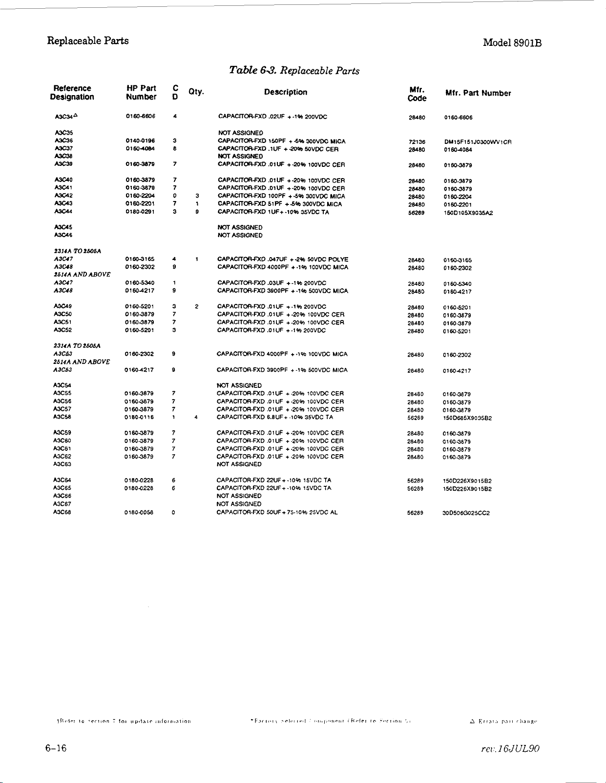
~
Replaceable
Reference
Designation
m34*
A3c35
A3C36
A3c37
mC3.3
A3Cs
KC40
-1
KC42
A3c43
A3c44
A3c45
-6
PJlJA
TO
AND
TO
LbObA
ABOVE
Z6ObA
A3U7
A3U8
Zb14A
A3W7
A3U8
-9
A3cso
Ax51
-52
2314A
A3C63
4b14A AKDABOVE
A3C63
AX54
Ax55
A3C56
Ax57
m5a
Ax59
AX60
A3C61
Ax62
A3C63
A3CW
Ax65
AX66
AX67
A3C68
Parts
HP Part
Number
0160-6606
01404196
01604084
0160-3879
01603879
01603879
0160-Po4
0160-2201
0180.0291
01603165
01602302
0160.5340
01 60-4217
0160-5201
01603879
01603879
0
160-520
0160-2302
01604217
0
1603879
0160-3879
01 603879
01804116
0160-3879
01603879
01 603879
01603879
01800228
01804228
01804058
Model
Table
C
Qty.
D
4
3
8
7
7
7
0
7
3
4
9
1
9
3
7
7
3
1
9
9
7
7
7
1
7
7
7
7
6
6
0
CAPACITORFXD .02UF + -1% 20oVDC
NOT ASSIGNED
CAPACITORFXD 1SOPF
CAPACmORFXD .1 UF
NOT
CAPACITORFXD
CAPACITOR-FXD .01W
CAPACITW-FXD .01W
3
CAPACITOR-FXD 100PF
1
CAPACITORFXD 5iPF
CAPACITORFXD lUF+ -10% 35VDC TA
9
NOT ASSIGNED
NOT ASSIGNED
1
CAPACITORFXD .047UF
CAPACITOR-FXD 4000PF
CAPACITOR-FXD .03UF +-1%2OOVDC
CAPACITOR-FXD 3SOOPF + -1% WOVDC MICA
2 CAPACITORFXD .OlUF +-1% 2OOVDC
CAPACITOR-FXD .OIUF
CAPACITOR-FXD
CAPACITOR-FXD
CAPAClTORFXD 4000PF + .l%
CAPACITOR-FXD 3900PF
NOT
ASSIGNED
CAPACITOR-FXD .OlUF +-2O% IOOVDC CER
CAPACITOR-FXD .OlUF +.20% 100VDC CER
CAPACITOR-FXD .OlUF
4
CAPACITOR-FXD 6.8UF+ -10% 35VDC TA
CAPACITOR-FXD .OlUF +-20% 100VDC CER
CAPACITOR-FXD .OlUF +-20% 1OOVDC CER
CAPACITOR-FXD .OIUF
CAPACITOR-FXD .OlUF
NOT ASSIGNED
CAPACITOR-FXD ZUF+ .lo% 15VDC TA
CAPACITOR-FXD 22UF+ -10% 15VDC ?A
NOT ASSIGNED
NOT ASSIGNED
CAPACITOR-FXD MUF+ 75.10% 25VDC AL
ASSWEO
6.3.
Replaceable Parts
Description
+
-5%
3OOVDC MICA
+
-20%
SOVDC
.01W
+-a% lOOVDC CER
+-a%
lOOVDC CEA
+
-20% IOOVDC CER
+
5%
3OOVDC MICA
+5%
300VDC MICA
+-2%
WVDC POLYE
+
-1% 100VDC MICA
+-XI%
.O
1
UF + -20% 1 OOVDC CER
.O
1
UF
lOOVDC CER
+
-1
%
200VDC
lOOVDC
+
-1% MOVDC MICA
+
-20% 1OOVDC CER
+-2o%
1OOVDC CER
+
-20% lOOVDC CER
CER
MICA
Mfr.
Code
28480
72136
28480
28480
28480
28480
28480
28480
56289
28460
28080
28480
28080
28480
28480
28480
28080
28480
28480
28480
28480
28480
56289
28480
28480
28480
28080
56289
56289
56289
Mtr.
Part
Number
0160-6606
DM15F151J0300WViCR
01604084
01603879
01 60-3879
01603879
01
60-Po4
0160-2201
lXID105X9035A2
01603165
01 60-2302
0160s340
01604217
0
160520
1
0160-3879
01603879
0 1 60-520
1
0160-2302
01604217
0160-3879
01 603879
0160-3879
1500685X903582
0160-3879
01603879
01604879
0160-3879
15OD226X90 1582
150D226X901582
300506G025CC2
8901B

Model
8901B
Replaceable
Parts
Reference
Designation
AX69
A3C70
A3C71
A3C72
A3C73
a74
-75
A3C76
A3Cn
A3CR1
A3CR2
A3Cw
A3CW
A3CR5
A3CR6
A3CR7
AXRB
A3Cm
A3L1
A3L2
A3w
MMPl
A301
2314A
TO
TO
2W5A
ABOVE
2505A
ABOVE
A3R1
2614A AND
A3RI
A3R2
A3R3
2314A
A3R4
2614A AND
A3R4
A3R5
A3R6
A3R7
A3R8
A3R9
A3R10
A3R11
A3R12
A3R13
A3R14
HPPart
Number D
01804058
01604134
01804116 1
0160-2055
0160-2055
01803879 7
01800197
01804187
1001o040 1
18014040 1
1901-1098 1
18014040
19010040
19014040 1
18014040
1901-1098 1
81404137 1
9100-1633
91404137 1
0890140021
23604113 2
1854-0477
0698-7353
0698-6942
06985091
07570349
0688-6343 5
06988191
07570280
06984085
06983159
06983161
07570441
07574441
07574438 3 40
07574441
C
Q~~.
0
1
8
8
8
8
1
1
1
0
7 1
7
9
0
8
5
5
3
0
5
9
8
8
8
Table
63.
Replaceable
Description
CAPACITOR-FXD SOUF+ 75.10% 2NDC AL
CAPACITORFXD POPF
NOT ASSIQNED
CAPACITORFXD 6.8UF+ -10% SVDC TA
CAPACKORFXD .OIUF
CAPACITCS-FXD
CAPACTTORFXD .01UF
53
CAPACITOR-R(D
CAPACITOA-FXD 2.2UF+-10%
DlODESWlTCHlffi 30V SOMA 2NS
DIODEMCHING
DlODESWlTCHlNG 1N4150 SOV 200MA 4NS
DlODESWlTCHlffi
DlODESWlTCHlNG
DlODESWlTCHlNG 3OV
DIODEMCHING 3OV SOMA
NOT ASSIGNED
DlOOESWlTCHlNG 1N41SO MV 200MA 4NS
INDUCTOR RFCH-MU) 1MH 596.2DX.45LG
1
INDUCTOR RFCH-MLD
INDUCTOR RFEH-MLD 1MH 596.2DX.45LG
COVER AUD DE-EMP
SCREWUACH
TRANSISTOR NPN 2NZ22A
1
RESlSTOR19K
RESlSTOR25K.II .125WFTC-0+-50
1
RESlSTOR45K 1%.125W FTC-0+-IO0
1
RESlSTOR22.6K 1%
2
RESlSTOA9K.1% .12W FTC-0+-25
RESISTOR
RESISTOR 1K 1%
NOT ASSIGNED
RESlSTOR2.61K 1% .125W FTC-O+-100
16
RESISTOR26.1K 1% .125WFTC-O+-1OO
3
RESISTOR 38.3K 1% ,125W FTC-O+
4
NOT
10
ASSIGNED
RESlSTOR8.25K lab .125W FTC-O+-IOO
RESISTOA8.25K 1% .125W FTC-O+-100
RESlSTOR5.11Kl% ,125WFTC-0+-100
RESlSTOR8.25K 1% .125WFTC-0+-100
.OlUF
2.2UF+
3OV
3OV SOMA
3OV
68UH
632
.25-IN-LG PAN-HD-PO2
1%
.125W FTC-0+-100
,125W
12.W
.1%.125W F TC
.12W
+
-5%
WVDC MICA
+M)-2096
lOOVDC CER
+80-209b
100VDC CER
+-20%
lOOVDC CER
-10% 2OVDC TA
20VDC
-MA 2NS
SOMA 2NS
SOMA
WS
0035
2NS
0035
Do35
2NS
0035
2NS
w35
5%
,166DX.385LG
SI
Tal 8 PD
FTC-0+-100
-
0
FTC-0+-100
TA
+
-100
.25
Parts
0-
60
0-
60
-
SOOMW
Mfr.
Code
56289
28480
56289
28480
28480
28480
56289
56289
28480
28480
8N171
28480
28480
28480
28480
9N171
28480
28480
28480
28480
00000
04713
19701
24546
24546
24546
28480
24546
24546
24546
24546
24546
24546
24546
24546
24546
Mfr.
Part Number
30D5060025CC2
01604134
153D685X9035B2
0160-2055
0
160-2055
01603879
lSOM25X9020A2
1SOM25X9020A2
1801.0040
18014040
lN4lSO
18014040
19014040
18014040
19014040
1N41M
91404137
8100.1633
81404137
0890140021
BY
ORDER
2WZA
MF4C1 /B.T0-1902+
C4-118-25024
Cd-118-T04502-F
C4-
06984243
0%-1
C4.118.TO-1001-F
Cd-118.70-2611-F
02-1/8-TO-2612-F
cd-ll8-TO-3832-F
Cd-118-108251 -F
Cd-118.TO-8251-F
Cd-lI8-10-5111-F
C4-118-TO8251-F
DESCRIPTION
ll8-TO-2262-F
&TO 1252-F

Replaceable
Parts
Model
8901B
Reference
Designation
A3R15
MR16
A3R17
A3R18
A3R19
MRM
MR21
A3Fm
A3R23
A3R24
A3W5
A3W6
MR27
A3R28
f314A
TO
A3R49
2606A
AND
ABOVE
TO
2505A
Ah'DABOVE
A3R29
2614A
A3R29
A3R30
A3R31
A3R32
A3m
ME.4
A3m5
P314A
A3R36
2614A
A3R36
A3R37
A3R38
A3R39
A3R40
A3R4 1
A3R42
A3R43
A3Pdd
A3R45
A3R46
A3R47
A3R48
A3R50
HP Part
Number
07570612
07574465
0757-0038
07570612
07574438
0683-2265
07570279
07574438
07574442
0698-7236
21003273
06983156
06988046 9
0698-6942
0698-7266
06984191
0698-7643
06994069
06984642
06984731
0698-6614
0~98-8307
0698-7643
0698-8731
0698-7251
0698-7224
06983157
06984731
06984731
06984731
06984731
06984731
0757-1094
0698-3159
06984731
Table
C
Qty.
D
NOT ASSIGNED
RESISTOR 1OK 196 .125WFTC-O+-100
29
RESISTOR lOOK 1% .125W FTC-0+-100
RESlSTCXIS.llKleb.l25WFTC-O+.1OO
RESISTOR
3
1
0
3
9
7
1
2
0
9 12
3
5
RESlSTOR5.11K 1%
RESISTOR
3
RESlSTOR3.16K 1% .12W FTC-0+-100
19
RESISTOR 5.11K 1% .125W FTC-0+-100
NOT ASSIGNED
RESISTOR (OK 1% .12W FTC-0+-100
RESISTOR 1K 196 .OSWFTC-0+-100
21
RESISTOR-TRMR2K 10% C SIDE-ADJ 1-TRN
2
7
RESISTOR 14.X 1% .125W FTC-0+-100
1 RESISTOR 16K .I% .125WFTC-O+-25
RESISTOR 2%
RESISTOR 14.7K 1%
RESISTOR 12.5K.1%.125WFTC-0+-25
RESISTOR 6.25K .l% .125W F TC
RESlSTOR,2.15M 1% .125W FTC-0+-100
RESlSTOR56.2K .1%.12NvFTC=O+-25
RESlSTOR4.8K .1% .IW FTC-O+-15
1 RESlSTOR7.W .1% .125W FTC-O+-25
RESISTOR7.bK .25% .125W FTC-O+-50
RESISTOR 6.25K .1% .125W FTC-0+-25
RESlSTOR4.8K.lW .1W FTC-O+-15
RESlSTOR4.22K 1%
3
RESISTOR316 1% .05WFTC-0+-100
10 2
RESISTOR 19.6K 1% ,125WFTC-0+-100
NOT
RESlSTOR4.8K.l% .lW FTC-O+-15
RESISTOR4.8K ,146 .lW FTC-O+-15
RESlSTOA4.8K ,146 .1W FTC-O+-15
RESISTOR4.8K.19b .lW FTC-O+-15
RESISTOR4.BK
RESISTOR 1.47K
RESlSTOR26.1K 1% .125W FTC-O+-lOO
RESISTOR4.8K .1% .lW FTC=O+-15
TOK
22M
ASSIGNEO
63.
Description
1%
.125W FTC-0+-100
59b.25W FC TC
.l%
.125W F TC
.1% .IW FTC-O+.15
1%
Replaceable
.125W
FTC-0+-100
-
BOO/+
-0
+
-50
.OW
FTC-0+-100
-
O+
-25
.OW
FTC-0+-100
,125WFTC-O+-100
Parts
1x)O
Mfr. Mfr. Part Number
Code
2454
6
24546 01-118-TO-1003-F
24546 0%-118.TO-5111-F
24546 C4-118-TO-1002-F
24546 01-118.TO.51ll-F
01121 CB2265
24546 C4.118-TO3161 -F
24546 C4-118-T0-5111-F
24546 C4.118-TO-1002-F
24546 C3.118-TO-1001 -F
28480 21003273
24546 C4-118-TO.1472-F
19701 MF4C1/8-T9-1602-B
24546 01.118.2502-F
24546 C3-118-TO-1472-F
i
970
19701 MFdC1/8-T9.6251-B
28480 0699-0069
28480 06988642
28480 06984731
28480 0698-6614
24546 01.1/8.T07401-F
1970
28480 06984731
24546 C3-118-TO4221-F
24546 C3-118.T0316R-F
24546 0%.1/8-TO-l962.F
28480 oma873i
28480 06984731
28480 06984731
28480 06984731
2.9480 06984731
24546 0%-1/8.T0-1471.F
24%
28480 06984731
0%-118-TO-1 002.F
1
MF4C 118.T9.1252-8
1
MMC 1/8-T9.625 1-8
6 cS-l/&-T0-26 12-F

Model
8901B
Replaceable
Parts
Table
Reference
Designation
A3R51
A
A3R52
A3R53
A3R54
A3R5SA 0698-6414 1 RESISTOR 1K .1%.1W FTC-O+J
A3R56
A3R57
A3W
A3R59
A3R60
A3R61
A3R62
A3R63
A3R&
A3R65
NTPi
A3TP2
A3TP3
A3TP4
A3TP5
A3U1
A3U2
A3U3
A3uS
A3u5
A3U6
A3U7
A3U8
A3U9
mulo
A3U11 18264783 9 IC OP AMP LW-NOISE 8-DIPC F'KG
2314A
TO
2426A
A3U12
A3G13
A3U14
A3V15
AN16
A3U
1
A3Ul8
A3U 19
A3U20
2422A
Alr'DAHOVE
7
A3U12
A31113
A3U14
A31115
HP
Part
Number
0698-6414 1 RESISTOR IK .1% .lW FTC-O+S
07574280
0757-1094 9 RESISTOR l.47K
06983644
07570280
07574439
07574401
07570001
0757-0442
0757-0442
07574280
07570280
0698-7272 1
12514600
12514600
12514600
12514600
12514600
18264413
18260413
1826-0413
18260753
18264371
18264059
18264783
18264783
18264753
18264783
18264582
18264582
18264582
18264582
18264606
18260606
18264606
18260606
1820-1 195
1820-1418 7 1
1820-1195
1820-1195
1820-1216
C
Q~~.
D
3
1
3
4
0
0
9
9 RESISTOR 10K 1% .125WFTC-O+-100
3
3
0
0
0
0
0
2
2 IC W AMP LW-BIAS-H-IMP0 TO.99 PKG
2 IC OP AMP LW-BIAS-H-IMP0 TO-99 PKG
3
1 6 IC
2 10 IC W AMP GP TO-99 PKG
9
9 IC OP AMP LW-NOISE 8-DIP-C PKG
3
9 IC
7 11 IC FF lTL LS D-TYPE POS-EDGE-TRIG COM
7 IC FF lTL
7 IC FF TTL LS 0-TYPE POS-EDGE-TRIG COM
3
RESISTOR
RESISTOR316 1% .12W FTC-O+-100
RESISTOR 1K 196 .12W FTC-O+-100
7 RESISTOR 6.81K 1% .12W FTC-O+-lOO
NOT ASSIQNED
49 RESISTOR 100 1% .12W FTC-O+-lOO
RESISTOR 100 1%
RESISTOR 1OK 1% .12W FTC-Oc-100
RESISTOR 1K
RESISTOR 1K 196 .125WFTC-O+-1OO
1
RESlSTOR31.W 1% .OWFTC-O+-lOO
CONNECTORSGL CONT PIN 1.14-MM-BSCSZ
CONNECTORSGL
CONNECTORSGL CONT PIN 1.14-MM-BSCSZ
CONNECTORSGL CONT PIN 1.14.MM-BSC-SZ
CONNECTORSGL COW PIN 1.14MM.BSC-SZ
IC OP AMP LW-BIAS-H-IMP0 TO-99 PKG
4
IC OP AMP LW.BIAS-H-IMPD WAD 14-DIPC
OP
6
IC OP AMP LW-NOISE 8-DIPC PKG
IC
OP
OP
IC SWITCH ANLG OUAD 16-DIPC PKG
IC SWITCH ANLG OUAD 1 6-DIPC PKG
IC SWITCH ANLG OUAD 16-DIP-C PKG
IC SWITCH ANLG OUAD 16.DIPC PKG
ANALOG SWITCH 4 SPST 16CERDIP
ANALOG SWITCH 4 SPST 1GCERDIP
ANALOG
ANALOG SWITCH 4 SPST 1 6CERDlP
IC DCDR TTL LS BCD.TO-DEC 4-TO-IO-LINE
IC DCDR TTL LS 3-TW-LINE 3-INP
63.
Replaceable
Description
1K 1%.125WFTC-O+-1OO
1%
.125WFTC-0+-100
.12W
FTC-O+-IOO
1%
.12W FTC-0+-100
COIST
PIN 1.14UM-BSCSZ
AMP LW-BlAS-H.IMPD TO-99
AMP LW-BIAS-H-IMP0 OUAD 14-DIP4
AMP LW-NOISE 8-DIPC PKG
SWlTCH
4
SPST 16CERDIP
LS
D-TYPE POS-EDGE-TRIG COM
PKG
Parts
SO
SO
SO
SO
SO
Mfr.
Code
28480
24546
24546
24546
28480
24546
24546
24546
24546
24546
24546
24546
24546
24546
28480
20480
28480
28480
28480
34371
34371
34371
047 13
27014
01295
52063
52063
04713
52063
52063
27014
27014
27014
27014
17856
17856
17856
17856
01295
01295
01295
01295
01295
Mfr.
Part
Number
06986414
C4.1/8-T0-1001C
C4-118-TO-1471-F
Cd-118-TO316RF
06986414
C4-118-TO-1001-F
C4-118-TO-6811-F
00.118-TO-101-F
C4-118-TO-101-F
C4-118-TO-1002-F
C4-118-TO-1002-F
C4-118-TO-1 001 -F
C4-118-TO-100
C3-118-TO3162-F
12510600
12510600
1251
12514600
12514600
HA2-2605.5
HA2-2605-5
HA2-2605-5
MCWOMBL
LF256H
LM;?OlAL
XR5534ACN
XR5534ACN
MC340MBL
XR5534ACN
XRS534ACN
LFI 320
LFI 3201
LFi3201 D
LF13201
D(YO1BK
DG20
E20
0020
SN74LS175N
SIJ74LS42N
SN14LS175N
SN74LS175N
SN74LS138N
0600
1
1
BK
1
EK
1
BK
1-F
D
D
D
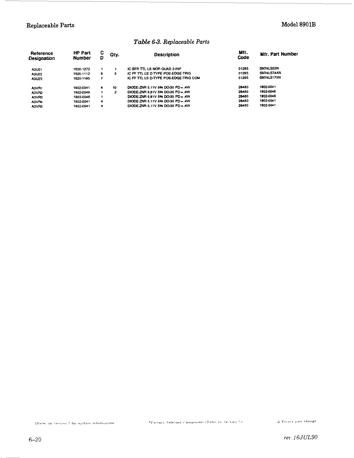
Replaceable
Parts
Model
8901B
Reference
Designation
MU21
Mu22
Mu23
A3VRI
MVR?
A3VFU
A3VR4
A3VM
HPPart
Number
1820-1272 1
1820-1112
1820-1195 7
1902-0041
19020048
1902-0048
1s024041 4
19024041
C
Q~~.
D
1
8
5
4
10
1
2
1
4
Table
63.
Description
IC
BFR
lTL
LS
ill.
lTL
NOR
LS
D-TYPE
LS
D-TYPE
6.8 1
5.11V5%
5.1
1V
V
5%
546
5%
IC
FF
IC
FF
DIODE-ZNR 5.11V 546
DIODE-DJR
DIODE-ZNR 6.81V
DIODE-ZNR
DIOOEZNR
Replaceable Parts
QUAD 2-INP
PQS-EDGE-TRIG
POSEDGE-TRIG
DO35
DO35
DO35
DO35
Do35
PD-
.4W
PD
-
.4W
PD-
.4W
PD-.4W
PD
-
.4W
COM
Mfr.
Code
01295
01295
01295
28480
28480
28480
2e.480
28480
Mfr.
Part
SN74LS33N
SN74LS74AN
SN14LS175N
lS020041
19020048
10024048
19020041
19024041
Number

Model
8901B
Replaceable
Parts
Reference
Designation
A4
A4
A4c1
A4C2
A4c3
A4c4
A4c5
A4C6
PAC7
MC8
A4c9
AAClO
A4Cll
A4c12
A4C13
A4C14
A4clS
AAC16
A4C17
A4C 18
A4c19
A4m
AAc21
AACZ
PAC23
A4C24
A4C25
AAC26
AAC27
A4C28
A4c29
AAC30
AAC3
1
AAC32
A4c33
AACM
A4c35
A4C36
A4C37
A4C38
MC39
A400
A40
1
A402
A4a3
A4w
A405
HP
Part
Number
08901-M)184 9 1
01604084
0180-1746
01804197
01804197
01804197
0160492 2 3
01604084
01604084
01604084
01604492 2
01804197
01604197
01604084
01604084
01604806
01804197
01804197
01604832
01804197
01604832
01804094
01804197
01804094
0180-1746
01804094
0180-1746
0160-5699
0160-5699
01604162
01604153
01604805
01604808 4
0160-5191
01604799 2
0180-1746
01804197
01604801 7
01603501 2
01804197 6
0160d812
01604791
01604795
0160-5719
C
Qty. Description
D
8
5
8
8
8
8
8
8
8
8
8
8
2
8
8
4
8
4
4
8
4
5
4
5
3 3
3
5
4
1
3
5
8
0
4
8
8
Table
FM
DEMODUUTOR ASSEMBLY
CAPACITORFXD .lUF
CAPACITOR-FXD 15UF+-lOW 20VDC TA
CAPACITOR-FXD 2.2UF+-lO% 20VDC TA
CAPACITOR-FXD 2.2UF+-10% 2UVDC TA
CAPACITORFXD 2.2UF+ -10% 20VDC TA
CAPACITOR-FXD 18PF
CAPACITORFXD
CAPACITOR4XD
CAPACITOR-FXD .lUF
CAPACITORFXD 18PF
CAPACITOR-FXD 2.2UF+-10%
CAPACITOR-FXD 2.2UF+-10% 2OVDC TA
CAPACITORFXD .lUF +-2O% SOVDC CER
CAPACITOR-FXD
1
CAPACITOR.FXD 39PF
CAPACITOR-FXD 2.2UF+ -1096 20VDC TA
CAPACITOR-FXD 2.2UF+ .lo% 20VDC TA
32
CAPACITOR-FXD .OlUF +-lo% lOOVDC CER
CAPACITOR-FXD 2.2UF+ -10% 2OVDC TA
CAPACITORFXD .01UF +-IO% lOOVDC CER
7
CAPACITOR-FXD lOOUF+ 75.10% 25VDC AL
CAPACITOR-FXD 2.2UF+ -10% 2OVDC TA
CAPACITOR-FXD lOOUF+ 75.10% 25VDC AL
CAPACITOR-FXD 15UF+ -10% 20VDC TA
CAPAClTORfXD 100UF+75-10% 25- AL
CAPACITOR-FXD 15UF+-lO% ZUVDC TA
CAPACITOR-FXD 20PF
CAPACITOR-FXD 20PF
CAPACITOR-FXD .022UF
1
3
CAPACITOR-FXD lOOOPF +-lo% 200VDC POLYE
2
CAPACITOR-FXD 47PF
CAPACITOR-FXD 470PF
1
CAPACITOR-FXD 240PF
1
NOT ASSIGNED
CAPACITOR-FXD 2.2PF
1
CAPACITOR.FXD 15UF
CAPACITOR-FXD 2.2UF+ -10% POVDC TA
CAPACITOR-FXD lOOPF
3
5
CAPACITORFXD 4UF
NOT ASSIGNED
CAPACITOR-FXD 2.2UF+ -10% 2OVDC TA
CAPACITOR-FXD ZOPF
5
1
CAPACITOR-FXD lOPF
CAPACITOR-FXD 4.7PF
2
CAPACITOR-FXD 620PF
1
63.
Replaceable Parts
+-20%
+
4%
.1
UF
+
-20%
.1
UF
+
-20%
+-2O%
+
5%
.1
UF
+
-20%
+
-5%
+
6%
+
-58 1OOVDC CER
+
-10%
+
-5%
+
5%
+
-5% lOOVDC CER
+
-.25PF 1OOVDC CER
+
-1
0%
+-5%
+
-1096
+5%
+
-5%
+
.SPF 1OOVDC CER
+
-5%
MVDC
CER
2UOVDC CER
MVDC CER
MVDC CER
MVDC CER
2OOMc
MVDC
50VDC CER
1 OOVDC CER
lOOVDC CER
2OOVDC POLYE
IOOVDC CER
1OOVM: CER
2GVDC TA
lOOVDC CER
MVDC MFTPOLYC
1OOVDC CER
IOOVDC CER
IOOVDC CER
CER
TA
0
+
-30
0
+
30
0
+
30
0 + 30
0
+
30
0
+
30
0
+
30
Code
28480
28480
56289
56289
56289
56289
28480
28480
28480
28480
28480
58289
56289
2ed80
28480
28480
56289
56289
28480
56289
28480
56289
56289
56289
56289
56289
56289
28480
28480
28480
28480
28480
28480
28480
28480
56289
56289
28480
28480
56289
28480
28480
28480
28480
Mfr. Part Number
08901
-60184
01604084
lMD156X902082
lMD225X9020A2
lMD225X9020A2
15OD22sx9020A2
01604492
0160dO84
01604084
0
1604084
01604492
lMD225X902OA2
150D225X9020A2
01604084
01604084
01604806
150DZ5X9020A2
150DZSX9020A2
01604832
1MD225X9020A2
01604832
3001
07Ga25DD2
150DZSX9020A2
30D107G025DD2
lMD156X9020B2
30D107G025DD2
lMD156X902082
01
60-5699
0
160-5699
01 604162
01604153
01604805
01604808
01 60-5691
01604799
150D156X9020B2
150D225X9020A2
01
604801
01603501
150DZ5X9020A2
01604812
01 604791
01604795
0160-5719

~
-
Replaceable
Reference
Designat ion
A4-6
A4-7
Ma8
MC49
A4cso
A4c51
A4CR1
A4CR2
A4CR3
A4CR4
A4CR5
A4CR6
MCR7
MCR8
MCR9
A4CRIO
A4CR11
A4CR12
A4CR13
A4CR14
A4CR15
AoCRl6
A4DSl
MDS2
A4Jl
A4L1
A4u
A4L3
PAL4
A4MPI
Parts
HP Part
Number
01604832
01 604822
0
1804 197
01 EO4832
01 604819
01604819
1901 -1 098
1901-1098
1901-1096
1901-1098
098
1901 -1
0890 1-80037
0890140037
0890
1-80037
08soia0037
19014518
19014518
19014518
19014518
1901-1098
1901.1098
1901.1098
19904325
19904325
1250.1m
21904124
29504078
220
1250-1
21
904
124
29500078
1 250.1
220
2 1904 124
29504078
91404098
9
1404096
91 00-2272
9100-2272
0890140020
2190~008
23604113
18544210
18544071
18534020
18534020
18544071
C
D
4
2
8
4
7
7
1
1
1
1
1
3
3
3
3
8
8
8
8
1
1
1
2
2
0
4
9
0
4
9
0
4
9
3
3
5
5
6
3
2
6
7
4
4
7
Table
Qty.
CAPACITORFXD .OIUF +-lo% lOOVDC CER
6
CAPACITOR-FXD lOOOPF
CAPACITOR.FXD 2.2UF+ ->OW MVDC TA
CAPACITOR.D(D .01UF +-lo% 100VDC CER
2
CAPACITOR-FXD 22OOPF + -5% lOOVDC CER
CAPACITOR-FXD POOPF
DIODESWITCHING 1N4150 5OV 200MA 4NS
DIODESWITCHING 1N4150 SOV MOMA 4NS
DIODESWITCHING 1N41SO 5OV
DIODESWITCHWG 1N4150 SOV MOMA 4NS
DIODESWITCHING 1N4150 5OV 200MA 4NS
4
MATCH DIODE
MATCH DIODE
MATCH
MATCH DIODE
28
DIODESM
DIODESM SIG SCHOTKY
DIODE-SM
DIODESM SIG SCHOlTKY
DIODESWITCHING 1N4150 50V XOMA 4NS
DIODEWITCHING lh44150 5OV 2OOMA 4NS
DIODE-SWITCHING IN4150 5OV 200MA 4NS
2
LED-LAMP LUM-INT- 8OOUCD IF-SOMA-MAX
LED-LAMP LUMNT
CONNECTOR-RF SMC M PC
WASHERLK IML T NO. 10 .195.IN-ID
NUT-HEX-DBLCHAM 1032-THD .067.1N-THK
CONNECTORAF SMC
WASHERLK INTL T NO. 10 .195.IN-ID
NUT.HEX-DBLCIiAM 10-32.THD ,067.lN-THK
CONNECTOR-RF SMC M PC
WASHER-LK IML T NO. 10 .195.IN-ID
NUT-HEX-DBLCMM 1032-THD ,067-IN-THK
2
INDUCTOR RFCH-MLD 2.2UH 10%
INDUCTOR RFCH-MLD 2.2UH 10%
2
INDUCTOR RFCH-ULD 47UH 10% ,105DX.26LG
INDUCTOR RFCH-MLD 47UH 10% ,105DX.26LG
1
COVER
WASHER-U( EXTT
12
SCREW-MACH 632 .25-lN-LG PAN-HD-POZI
4
TRANSISTOR NPN 2112222
TRANSISTOR NPN
TRANSISTOR PNP
23
TWNSISTOR PNP
TRANSISTOR NPN
DIODE
SIG
SIG
FM
D MOD
63.
Description
SET
SET
SET
SET
SCHO''
SCHOlXY
-
NO.
SI
SI
SI
SI
Replaceable Parts
+
-5%
100VDC CER
+
4%
100VDC CER
MOMA
4NS
BOOUCD
IF
-
SOMA-MAX
SOOHM
M
PC 50-OHM
50-0HM
6
,141-IN-ID
SI
TO18 PD
-
PD
c
3OOMW
PD
I
300hNil
PD
-
300MW
PO - 300MW
Ff
FT
FT
Ff
=
I
-
-
5OOMW
200MHZ
lSOMH7.
150MHZ
POOMHZ
Mfr.
Code
28480
28480
56289
2mo
28480
28480
9N171
9N171
9N171
9N171
ON171
28480
28480
28480
28480
28480
26480
28480
28480
9N171
9N171
9N171
28460
28480
28480
28480
28460
28480
28480
28460
28480
28480
28480
28480
28480
28480
28480
28480
284eo
00000
04713
28480
28460
28480
28480
Model
Mfr.
Part Number
01604832
0
1604622
150D225X9020A2
01604832
01604819
0
16048 19
lN4150
lN4150
1N4150
1N4150
1N4150
0890 1-80037
08901-80037
0890180037
0890
160037
19014518
19014518
19014518
190 145 18
1N4150
1w150
1N4150
50824403
50824403
1250-1220
21904124
29504Q78
220
1250-1
21904124
29504078
1250.1 220
2 1904 124
29504078
91404098
91404098
9100-2272
91002272
06901-00020
2190-0008
ORDER BY DESCRIPTION
2N2222
18544071
18534020
18534020
18544071
8901B

Model
8901B
Replaceable
Parts
Reference
Designation
A4024
A4025
A4026
Ma27
A4028
A4029
A4030
A4031
A4032
A4033
A4a34
A4035
A4R1
A'l
R2
A4R3
A4R4
MR5
A4R6
A4R7
A4R8
A4R9
A4R10
AdR11
A4R12
A4R13
A4R14
A4R15
A4R16
HP Part
Number
1853-0007
18530020
18550020
18540071
18530020
18584032
1853-0007
18534007
0
1854421
18544210
18544071
18534007
18544475
18584032
18544071
18554020
18554049
18544637
12004 173
18544071
18534007
18540637
lZQ0-0173
18544071
18544637
120041 73
1205436 1
18540071
18580032
18544071
18534020
18544637
12004173
12054361
18544071
18550020
0757440 1
06983430
06983155
07574279
07570279
0757-1094
07570280
55
0898-31
07570280
07574280
07574280
06983155
06984082
06984082
06983 1 55
06983155
C
D
8
7
7
6
6
7
7
5
8
7
8
1
1
5
7
7
1
5
7
1
5
3
7
8
7
4
1
5
3
7
8
0
5
1
0
0
9
3
1
3
3
3
Table
Qty.
TRANSISTOR PNP 2N3251
TRANSISTOR PNP
TRANSISTOR PNP
TRANSISTOR NPN
TRANSISTOR PNP
5
TRANSISTOR ARRAY 14-PIN PLSTC DIP
TRANSISTOR
TRANSISTOR PNP 2N325i
TRANSISTOR NPN
TRANSISTOR NPN 2Nm2
TRANSISTOR NPN
TRANSISTOR PNP 2N3251
TRANSISTOR-DUAL NPN PD
TRANSISTOR ARRAY l4PlN PLSTC DIP
TRANSISTOR NPN
4
TRANSISTOR
TRANSISTORJFET DUAL NCHAN D-MODE
2
19
6
TRANSISTOR NPN 2N2219A
INSULATOR-XSTR DAPGL
TRANSISTOR NPN
TRANSISTOR PNP 2N3251
TRANSISTOR NPN 2N2219A
INSULATOR-XSTR DAPGL
TRANSISTOR NPN
TRANSISTOR NPN 2N2219A
INSULATOR-XSTR DAPGL
2
HEAT
TRANSISTOR NPN
TRANSISTOR ARRAY 14.PIN PLSTC DIP
TRANSISTOR NPN
TRANSISTOR PNP
TRANSISTOR NPN 2N2219A
INSULATOR-XSTR DAPGL
HEAT
TRANSISTOR NPN
TRANSISTOR J-FET NCHAN D-MODE TO18
RESISTOR 100 1% .125W FTC-O+-100
RESlSTOR21.5 1%
RESISTOR4.64K 1% .12W FTC-0+-100
22
RESlSTOR3.16K 1% .125W
RESlSTOR3.16K 1% .12WFTC=O+.100
RESISTOR l.47K 1% .12W
RESISTOR 1K 1% .12W FTC-0+-100
RESISTOR4,MK 1%.12WFTC-O+-100
RESISTOR 1K 1% .125W FTC-0+.100
RESISTOR
RESISTOR lK1% .125WFTC-0+.100
RESISTOR 4.'64K 1% ,129'4. F TC
RESlSTOR4br 1% .125W FTC-0+-100
RESISTOR464 1% .125W FTC-O+.lOO
RESISTOR4.64K 1% .125W FTC-0+-100
RESISTOR4.64K lob .12W FTC-0+-100
63.
Description
SI
SI
SI
SI
PNP
2W251
2-
SI
SI
J-FET
NCHAN D-MODE TO18
SI
SI
SINK
SGL T05frW9CS
SI
SI
SI
SINK
SGL TO-5ffW9CS
SI
.12W
1K 1% .125W FTC-0+-100
Replaceable
SI
TO18 PD
PD-
300MW
PD-300MW
PD-
WOW
PD-
3wMW
SI
SI
SI
SI
PD
-
WOW
SI
-
PD
-
3OOMW
SI
PD
-
3OOMW
SI
SI
PD
-
300MW
SI
PD- 300MW
PD - 300MW
PD-
300MW
SI
PD
-
300MW
FTC-0+-100
F
F
-36OMW
Ff-
lSOMHZ
Ff-
150MHZ
FT
-
2C€MHZ
FT-
1WMHZ
TO18 PO-36OMW
TO18 PD-3wMW
TO18 PD
-
Tat8 PD-
FT
-
ZQOMHZ
TO18 PD-360MW
750MW
FT
-
200MHZ
TO5 PD
FT-
MOMHZ
TO-18 PD-
TO5 PD - 8OOMW
FT
-
2OOMHZ
TO5 PD
FT-
200MHZ
FT
I
200MHZ
FT-
150UHZ
TO5 PD
FT
-
20OMHZ
TC-O+-lOO
TC-O+-lOO
-
0
+
-100
Parts
50OMW
50OMW
SI
SI
-
8OOMW
360MW
-
8OOMW
-8OOMw
SI
Mfr.
Code
04713
28480
28480
28480
2wao
3L585
04713
04713
04713
04713
28480
04713
28480
3L585
28480
28480
28480
01295
28480
28480
04713
01295
28480
28480
01295
28480
13103
28480
3L585
28480
28480
01295
28480
13103
28480
28480
6
24%
03888
24546
24546
24546
24546
24546
24546
24546
24546
24546
24546
24546
24546
24546
24546
Mfr.
Part
Number
2N3251
18534020
18534020
18544071
18530020
CA3146E
2N3251
2N3251
2N2222
2m22
18544071
2N3251
18544475
CA3146E
18540071
18550020
18550049
2N2219A
12000 173
18544071
2N3251
2N2219A
12004173
18540071
2N2219A
120001 73
222%
18540071
CA3 14 6E
18540071
18530020
2N2219A
120001 73
222%
18540071
18550020
Cd-i/8-To-iO 1 -F
PMES5-118.TO-21 R5.F
Cd-1/8-T0464
C4-1/8-T0-3 161 -F
Co-1/8'10-3
Cd-l/&TO-1471-F
CII.118.TO.100 1 -F
Cd-ll8.TOd641-F
C4-1/8.TO-1001-F
Cd-118.TO-I
Dz-1/8.TO-1001-F
Cd-ll8.TO464 I-F
C4-118-TO4640-F
C4-1/8-T04640-F
c4-118-TO464
C4-1/8-TOd% 1-F
1 6 1
00
1
1
I-F
-F
-F
-F

Replaceable
Parts
Model
8901B
Reference
Designation
MR17
A4R18
A4Rl9
MR20
A4R21
MR22
A4Rn
Am24
AAW5
MW6
MW?
MW8
A4m
A4R30
MR31
MR32
A4m
MR34
MR35
MR36
&Fa7
A4m
AIR39
A4R40
A4Wl
A4R42
A4W3
A4W
A4R45
MW6
MW7
AIR48
A4R49
MR50
A4R51
A4R52
A4R53
A4W
MR55
AIR56
A4R57
A4R58
A4R59
A4R60
A4R61
A4R62
A4R63
A4RW
MR65
AIR66
HP
Part
Number
07574280
07574279
07574280
07574280
07570280
06383155
06983155
06984082
06983155
06383155
07570280
07574279
07574280
07570280
07574280
069831
55
06983155
06983155
07574280
06983155
07574199
06984084
0757-0465
07570465
07574280
06984082
07574442
06383160
07574401
07570403
06988833
21003273
06983904
07574442
07574442
06983441
07574442
06983430
0698330
06983441
06984084
07574400
07574199
0698-3041
07574346
06983441
06983441
06983430
Table
C
Qty.
0
3
0
3
3
3
1
1
7
1
1
3
0
3
3
3
1
1
1
3
1
3
9
6
6
3
7
9
8
0
2
2
1
8
9
9
8
9
5
5
8
9
9
3
8
2
8
B
5
RESISTOR 1K 1% .125WFTC-0+-100
RESlSTOR3.16Kl% .125WFTC-0+-100
RESISTOR
RESlSTORlK 1% .125WFTC-O+-1OO
RESISTOR 1K
RESlSTOR4.W
RESlSTOR4.64K
RESISTOR464 1% .125WFTC-0+-100
RESlSTOR4.64K
RESlSTOR4.64K 1%.125WFTC-0+-100
RESlSTORlK1%.125WFTC-O+-100
RESISTOR
RESlSTORlK 1% .125WFTC-0+-100
RESISTOR 1K
RESlSTORlK1%.125WFTC-0+-100
RESlSTOR4.MK 1% .125WFTC-O+-100
RESlSTOR4.W 1% .125W FTC-0+-100
RESlSTOR4.64K 1% .12W FTC-0+-100
RESISTOR IK 196.125WFTC-0+-700
RESlSTOR4.64K 1% .12W FTC-0+-100
RESISTOR 21.5K 1% .12W F TC-O+-IOO
21
RESlSTOR2.15K 1% .125W FTC-0+-100
RESISTOR 1OOK 1% .125W FTC-O+-100
RESISTOR 1OOK 1% .125W FTC-O+-100
RESISTOR 1K 1% .12W F TC-O+-100
RESISTOR464 1% .125W FTC-0+-100
NOT ASSIGNED
NOT ASSIGNED
RESISTOR 10K 1% .125W F TC
7
RESlSTOR31.W 1% .12W FTC-O+-rOO
RESISTOR100 1%.125WFTC=O+-100
RESISTOR 121
5
RESISTOR 1OK .1%.125W FTC-O+-10
1
RESISTOR-TRMR 2K 10% C SIDEADJ 1.TRN
RESlSTORl4.7K.l% .1W FTC-O+-10
1
RESISTOR 1OK
RESISTOR 10K 1% .125WFTC-O+.lOO
RESISTOR 215 1% .125W F TC
13
RESISTOR 1OK 1% .12W FTC-0+-100
RESlSTOR21.5 1% .125W FTC-0+-100
RESlSTOA21.5 1%
RESISTOR
RESlSTOR2.15K 1% .125W FTC=O+.IOO
REStSTOR90.9 1% .125WFTC-0+-100
RESlSTOR21.5KlQb .lZWFTC-O+-lOO
RESlSTOA2151%.125WFTC-O+-100
RESISTOR10 1% .125WFTC-O+-100
16
RESISTOR 215 1% .125W F TC-0+-100
RESlSTOR2151%.125WFTC-O+-100
RESlSTOR21.51% .125WFTC-0+-100
63.
Replaceable
Depcription
1K
1%
.125WFTC-0+-100
1%
.125W FTC-O+-IOO
1%
.12W FTC-0+-100
1%
.125W FTC-0+-100
1%
.125W FTC-O+-IOO
3.1%
1% .125W F TC-
1
%
.125W F TC - 0 + -100
1%
.125WFTC-0+-100
1% ,125W
.125W
215
1% ,125W F TC-
0
+
-
0
+
-100
FTC-O+.lOO
I
0
+
-100
FTC=O+-100
0 + .lOO
Parts
-100
Mff.
Code
24546
24546
24546
24546
24546
24546
24546
24546
24546
24546
24546
24546
24546
24546
24546
24546
24546
24546
24546
24546
24546
24546
24546
24546
24546
24546
24546
24546
24546
24546
28480
28480
28480
24546
24546
24546
24546
03888
03888
24546
24546
24546
24546
24546
24546
24546
24546
03888
Mfr.
Part
Number
C4-118.TO-1001 .F
W-1
18.T03161 .F
C4-118.TO-1001+
C4-1/8-T0-100
C4-118-TO-1001 -F
C4-1
C4-118-TO4641-F
C4-l18.TO464O.F
C4-118.TO464
cO.1/8.T04641 .F
C4-1/8.TO-lOOl-F
C4-1/8.T03161$
00-118.TO-1001
c4-l18.TO-100 1 -F
C4-1/8-TO-1001+
C4-118-TO4641 .F
C4-ll8-TO4641 -F
C4-118-TO464
C4-118-TO-1001 -F
C4-118-TO464
C4.118-TO-2152-F
C4.118-TO-2151-F
C4-118-TO-1003-F
02-118.TO-1003-F
C4-1/8-TO-100 1 -F
a-118.TO-1002-F
C4.
C4-118.TO.101-F
C4.118-TO-121R-F
0698am
21 003273
06984904
C4-l/e.TO-1002-F
C4-118-TO.1002.F
C4.1I8-TO-215R-F
C4-1/8-TO-1 002-F
PME55-118.TO-21 RS-F
PME
C4.lI8-TO-215R-F
0%-118-TO-21 51 -F
C4.118.TO.90R9-F
C4-lI8.TO-2152-F
c4.118-TO-215R-F
C4-lI8.TO-1ORO-F
C4-118.TO-215R-F
CZ-
PME55-1R-TO21 R5-F
1
I8.TO464 1 f
1
1
1
118 -TO3 1 62-F
55-
1
/&TO -2 1 R5-F
1
I8 .TO2 1 5R-F
.F
-F
f
-F
-F

Model
8901B
Replaceable
Parts
Reference
Designation
MR67
A4R68
A4R69
MA70
A4R71
A4R72
A4R73
MR74
MR75
MR76
MR?7
MR78
MR78
MR80
MRBl
MRB2
MR83
A4Re.4
MR85
MR86
A4RB7
A4R88
A4RB9
WR90
PdR9
1
A4R92
AAR93
A4R94
A4w5
A4R96
A4R97
A4R98
A4R99
A4RlOO
0
1
PdRl
A4R102
A4R103
PdR104
PdR105
A4R106
A4TP1
MTP2
A4TP3
A4TPb
A6TP5
MTPG
ILQVRi
HP Part
Number
07574442
07574346
06984731
07574280
06984731
06983155
07574280
06984084
06986821
07574260
06984082
06984084
07574280
0698a432
0698-32
06983160
06984084
07574442
2100-3352
0698a54
06984083
07574465
07574279
07574260
06984082
07570279
06984549
07574260
06984731
07570280
06903438
07574395
06994139
06983155
0698-8827
07574280
06983160
0757-0442
06983155
06983446
1251
4600
12514600
1251 4600
12514600
1251 4600
12510600
19024680
Table
Qty.
D
9
2
9
3
9
1
3
9
82
3
7
9
3
75
7
8
9
9
72
35
8
6
0
3
7
0
73
3
9
3
3
12
7
1
4
3
6
9
1
37
0
0
0
0
0
0
79
RESISTOR 10K 1% ,125W FTC-0+-100
RESISTOR 10 1% ,125W FTC-0+-100
RESlSTOR4.8K .1% .lW FTC-O+-15
RESISTOR
RESlSTOR4.8K .l% .lW FTC-0+-15
RESlSTOR4.64K
RESISTOR 1K 1% .12WFTC-O+-100
RESlSTOR2.15K 1% .12W FTC-0+-100
RESlSTOR5.62 1% .125W FTC-0+-100
RESISTOR
RESlSTORb64 1% .125W FTC-0+-100
RESISTOR 2.15K 1% .12W
RESISTOR
RESlSTOR26.1 1% .125W FTC-0+-100
RESlSTOR26.1 1% .12W FTC-O+-100
RESlSTOR31.6K 1%.125W FTC-0+-100
RESlSTOR2.15K 1% .12W FTC-0+-100
RESlSTORlOK 1% .125WFTC-O+-100
RESISTOR-TRMR IK 10% C SIDE-ADJ 1-TRN
RESlSTOR215K 1% .125WFTC-0+-100
RESlSTOR1.96K
15
RESISTOR lOOK 146 .12W FTC-0+-100
RESlSTOR3,16Kl% .125WFTC-0+-100
RESlSTORIKlM .125WFTC-0+-100
RESISTOR464 1% .125W FTC-0+-100
RESlSTOR3.16K 1% ,125W FTC-0+-100
RESlSTOR2.1KSW .lW FTC-O+-5
RESlSTORlK
RESlSTOR4.8K ,146 .lW FTC-O+.15
RESlSTORlKlW .125WFTC-O+-100
RESISTOR 147 1% .125W FTC-0+.100
RESlSTOR56.2 1% .125WFTC-O+-100
RESISTOR660 .l% .1W FTC-O+-lB
RESlSTOR4,MK 1% ,125W FTC-0+-100
RESlSTORlM 1%.125WFTCIO+-T0O
12
RESISTOR 1K 1% ,125W FTC-O+-100
RESISTOR31.6K 1% ,125W FTC-0+-100
RESISTOR 10K 1% .125W FTC-0+-100
RESlSTORb.MK l%.125W FTC-0+.100
RESISTOR383 1% .125W FTC-0+-100
CONNECTORSGL CONT PIN 1.14-MM-BSC.SZ
CONNECTOR-SGL CONT PIN 1.14-MM-BSCSZ
CONNECTOR-SGL COM PIN 1.14-MM-BSC-SZ
CONNECTOR-SGL CONT PIN 1.14-MM-BSCSZ
CONNECTOR.SGL CONT PIN 1 .?4-MM-BSC-SZ
CONNECTOR-SGL CONT PIN 1.14-MM-BSCSZ
DIODE-ZNR
63.
Replaceable
Description
1K 1%.125WFTC-0+-100
1%
.12W FTC-0+-100
1K 1%.125WFTC-0+-100
F
1K 1% .12W FTC-0+-100
1%
1%
.125WFTC-0+-100
1
N927
6.2V
TC-O+ -100
,125W FTC-0+.100
546
007
PD
-
.4W
Parts
SO
SQ
SO
SO
SO
SO
Mfr.
Code
24546
24546
28480
24546
28480
24U6
24546
24546
28480
24546
24546
24546
24546
02888
03888
24546
24546
24546
28480
24546
24546
24546
24546
24546
24546
24546
28460
24546
28480
24546
24546
24546
28480
24546
28480
24546
24546
24546
24546
24546
26480
28480
28480
28480
28480
28480
24046
Mfr.
Part
Number
C4-118-TO-1002-F
C4-118-TO-1ORO-F
06988731
0%-1/8-TO-I 001 -F
06984731
Cp-lm-TO464 1 -F
C4-118-TO-1001 -F
W-118-TO-2151 -F
06984821
C4-118-TO-1001-F
C4-118-T04MO-F
C4-118-TO-2151-F
C4-118-TO-I 001 -F
PME55-118-TO-26R1-F
PME55-1/8-T0.26Rl -F
01-118-TO31 62-F
C4-118-TO-2151-F
C4-118-TO-1002-F
21003352
C4-118-TO-2153s
CX-118-TO1961 -F
C4-118-TO.1003-F
C4-ll8.TO3161 -F
C4-ll8-TO-1001-F
C4.118-T04640-F
C4.118-TO3161-F
06968549
c4-118-TO-1001 -F
06988731
C4-116-TO-1001-F
c4-1
18-TO-147R-F
c4-118-TO-56R2-F
06994 139
a-iW-TOaM1-F
06988827
C4-118-TO.lOO1-F
C4.118-TO-3162-F
C4.118-TO-1002-F
C4.118-TO4641
c4.118.TO-383R-F
12514600
12514600
12514600
12514600
12514600
12514600
1
N827
-F

Model
8901B
Replaceable
Parts
Reference
Designation
HP Part
Number
A5
2314A
TO
A5C28
ASC30
A5C32
A5C33
AX34
AX35
TO
AND
-26
2644A
2636A
MOVE
0180.2929
01 80-1 746
0180-1746
0180-1746
01603879
01603879
0180-1746
01804197
01800094
01804374
01604387
01804374
01604576
0
180-1 704
0
1804374
01603879
01804374
01 6035O1
01604970
01604576
603878
0
160-3501
01 604576
01604576
01600576
0
180-2929
01604807
01 60497
01604576
01 604576
0
1804
197
01604805
A6 08902-60005
2660A
A6 08902-601
4635A
A6 08901 -60284
AX1
A5C2
ASC3
A542
AX5
AX6
A5c7
AX8
A5C9
A5C10
ASCll
A5c12
ASC13
A5C14
ASCl5
A506
A5C17
AX18
AX19
AX20
2314A TO2627A
A6CZI 01
A6C22 01603402
A5C23
AIC24 01603501
AX25 01603402
2G35A AXDABOVE
AX21
ASC26
A5C27
A5C29
A5C31
C
Oty.
D
41
11
0
1
01
7
5
8
4
36
43
3
5
51
3
7
3
2
31
5
6
51
23
2
2
2
5
5
5
8
34
61
5
5
8
1
Table
63.
Replaceable Parts
Description
VOLTMETER ASSEMBLY
VOLTMmR ASSEMBLY
VOLTMETER ASSEMBLY
CAPACITOR-FXD 68UF+-lO% lOVDC TA
CAPACITOR-FXD lSUF+ -10%
CAPACITOR-FXD 15UF+
CAPACITOR-FXD 15UF+ -10%
CAPACITORFXD .OlUF
CAPACITOR-FXD .OIUF
CAPAClTORFXD lSUF+-lOW
CAPACITOR-FXD 2.2UF+-lO% 2OVDC TA
CAPACITOR-FXD 1OOUF+ 7510% 25VDC AL
CAPACITORFXD
CAPACITOR-FXD 47PF
CAPACITORFXD lOUF+ -10% 20VDC TA
CAPACITOR-FXD .IUF +-20% SOVDC CER
CAPACITORFXD 47UF+ -10% 6VDC TA
CAPACITOR-FXD lOUF+-10% ZOVDC TA
CAPACITORFXD .OlUF + -20%
CAPACITOR-FXD lOUF+ -10% 20VDC TA
CAPACITOR-FXD 4UF
CAPACITOR-FXD .47UF
CAPACITOR-FXD .1UF
CAPACITOR-FXD 100OPF +-2O% lOOVDC CER
CAPACITOR-FXD 1UF
CAPACITOR-FXD 4UF
CAPACITORFXD 4UF
CAPACITOR-FXD 1UF
NOT ASSIGNED
CAPACITOR-FXD .IUF +30% 50VDC CER
CAPACITOR-FXD .lUF
CAPACITOR-FXD .IUF
CAPACITORFXD 68UF+ .lo% lOVDC TA
CAPACITOR-FXD 33PF
CAPACITOR-FXD .lUF +-I% lOOVDC POLYSTY
CAPACITORFXD .lUF
CAPACITOR-FXD .1UF
CAPACITOR-FXD 2.2UF+.10% ZOVDC TA
CAPACITOR-FXD 47PF
lOUF+
MVDC
-10%
+-a%
+
-20%
-10% POVDC TA
+
-5%
+
-10% SOVDC MET-POLYC
+
-10% 8OVDC POLYE
+
-20% SOVDC CER
+-5%
+.lo%
+.lo%
+-5%
+
-209% SOVDC CER
+
-20% BOVDC CER
+
-5%
+
-20% 5OVDC CER
+
-20% SOVDC CER
+
-5%
TA
20VDC TA
MVDC
TA
lOOVDC CER
lOOVDC CER
POVDC
TA
2OOVDC CER
lOOVDC CER
BOVDC MET-POCYC
SOVDC MET-POLYC
SOVDC MET-POLYC
SOVDC MET-POLYC
lOOVDC CER
1
OOVDC
0 + 30
CER
O+
0 + 30
30
'lr.
Code
28480 08902-60005
28480 08902.60101
28480 08901-60284
28480
56289 1 SOD1 56X90x)B2
56289 lMD156X90MB2
56289 150D156X902082
28460 01604879
28480 0160.3879
56289 1 SOD1 56x902062
56289 150D225X90MA2
56289 30Dl07G025DD2
56289 150D106X9020B2
28480 01604387
56289 150D106X9020B2
28480 01 604576
56289 lSOD476X9006B2
56289 150D106X90MB2
28480 01603879
56289 150D106X9020B2
28480 01603501
28480 01604970
28480 01604576
28480
28480 01603402
28480
28480 01603501
28480
28480 C1604576
28480 01606576
28480
28480 0180.2929
28480
28480 01604397
28480
28480 01604576
56289 150D225X9020A2
28480 01604805
Mfr.
Part Number
0180-2929
0160-3878
0160-3501
o
1603402
01
604576
01604eo7
01604576

Replaceable
Parts
Model
8901B
Reference HP Part
C
Designation Number D
19014040
1901.1098
1901-1098
1901.1098 1 DlOOESWlTCHlNG 1N4150
19010518
19010040 1 DIODESWITCHING 3OV 50MA 2NS
19014040
19014518
19014040 1 DIODESWITCHING 30V SOMA 2NS
19010040 1 DlOOEsWrrCHlNG WV SOMA 2NS
1901-1098
19014040
le014040
19010880
1901-1098
ASCRI
6
A5Ll 91404210
MMPl
As01
A5Q2
A5Q3
A504
A505
A506
A507
A5R1
A5R2
A5R3
2314A
TO
2443A
ASR4
2449A
AND
A6R4
A5R5
A5R6
A5R7
A5R8
A5R9
A5R10
A5R11
A5R12
ASR13
A5R14
ABOVE
1901-1098 1 DIODESWITCHING 1W150
089oi4ooi9
21904008
23604113
18544810
18534020
18546477
18534020 4
18550014
18534020
18544810 2 TRANSISTOR NPN
18104126
21004358
06988~ 7
06990074 9 2 RESISTOR 14.7M 1% .125W FTC-O+-IM
06994073
07574288
06984549 7 RESlSTOR2.1K
07574280
06986731 9
07574442
07576416
07574401
07570442
06983154
06983132
8
8
1 DlODESWlTCHlNG 1N4150 5OV 200MA 4NS
1 DIODESWITCHING 3OV SOMA 2NS
1
7
3
3
2 SCRRN-MACH 6-32 .25-IN-LG PAN-HD-POZI
2 7 TRANSISTOR NPN
4
7 TRANSISTOR NPN 2N2222A
4
4
1 1
3
8
1
3
9
7 RESISTOR511 1% .12W FTC-0+-100
0
9 RESISTOR 1OK 1% .125W FTC-0+-100
0
4
Table
Q~~.
1
1
1
1
1 DlODESWlTCHlNG 1N4150 5OV
1
DIODESWITCHING 3OV SOMA 2NS
DIODESWITCHING 1N4150 SOV 200MA
DIODESWITCHING 1N4150 50V 2OOMA 4NS
DIODESU
DIODESWITCHING 3OV SOMA 2NS
DIODESM
DIODESWITCHING 30V SOMA 2NS
9
DIODEGEN PRP 125MA
8
INDUCTOR RFCMLD lOOUH
1
COVERVOLTMTR
WASHER-LK EXTT
TRANSISTOR PNP
TRANSISTOR PNP
2 TRANSISTOR J-FET 21'14393 NCliAN D-MODE
TRANSISTOR PNP
NEIWORK-RES 14-DIP1O.OK
2 RESISTOR-TRMR 1M 2096 C SIDE-ADJ 1-TRN
RESlSTOR2.1K.5% .lW FTC-O+-5
RESISTOR TOM 196 .125W FTC-O+-150
3
RESlSTOR9.09K 1% .125W FTC-0+-100
RESlSTORlK 1%.125WFTC-0+-100
RESISTOR 4.8K .l% .lW F TC
RESISTOR
RESISTOR
12 RESlSTOR4.22K 1%.125WFTC-0+-100
RESISTOR261 1% .125W FTC-O+-lOO
11
63.
Replaceable
Description
SIG
SCHOTTKY
SIG
SCHOlTKY
.5%
1OK
lab .125W FTC-O+-100
100
1% .125W FTC-0+-100
5OV
Do35
50V
NO.
6.141-IN-ID
SI
PD-
625MW
SI
PD-300MW
SI
PD-
300MW
SI
PD
-
3OOMW
SI
PO 625MW
.lW FTC-O+-B
SI
OHM
Parts
Do35
4NS
200MA 4NS
Do35
Do35
Do35
Do35
Do35
Do35
2OOMA
4NS
200MA 4NS
5%
,166DX.385LG
FT-2OOMHZ
FT-
ISOMHZ
TO18 PD - 500MW
FT-
ISOMHZ
FI
-
1
SOMHZ
FI
-
20OMHZ
X
13
-
O+
-15
Mfr.
Code
28480
9N171
9N171
9N171
28480
28480
28480
28480
28480
28480
9N171
28480
28480
28480
9N171
9N171
28480
28480
28480
00000
28480
28480
04713
28480
04713
28480
28480
1
la6
28480
28480
28480
28480
19701
28480
24546
28480
24546
24546
24546
24546
22546
24546
Mfr.
Part
Number
190 14040
1W150
1N4150
11'14150
19014518
19014040
1901 4040
19014518
19014040
190 14040
11'14150
190 14040
19014040
190 14880
11'14150
1N4150
91404210
0890140019
21904008
ORDER
BY
DESCRIPTION
18544810
18534020
2N2222A
18534020
21'14393
18534020
18544810
760-l-RlOK
21 003358
06986549
06994074
06994073
MFdC118.TO-909
06984549
c4.il8.To-1001-F
06988731
c4-1/8-To-1002-F
Cd.ilB.TO-5i IR-F
Cd-i18.To-io
Cd-118-TO.1002-F
c4-118-TO4221 -F
c4.118-TO-2610-F
1
-F
1
-F

Model
8901B
Replaceable
Parts
Reference
Designation
4314A
TU
2443A
A5R15
2449A AND
AbR15
ASR16
ASR17
ASRl8
ASRl9
ASm
A5Wl
AS42
Asfm
MR24
ASR25
A5R26
ASR27
ASR28
ASP23
A5R30
A5R31
A5R32
A5W3
A5R34
A5W5
A5R36
~5~7
A5R38
2314A
A5R39
2449A
A b R39
A5R40
ASPA1
ASPA2
ASR13
2314A
A5R44
A5R45
A6R4G
A6R47
AbR48
AM49
ASRM
2635A AND
A6R44-R50
MOVE
TO
2443A
AND ABOVE
TO
262iA
ABOVE
HP
Part
Number
06990074
0699.0073
0757441 6
0698.0083
21003358
07570461
06983150
07574346
06994222
21003351
0757-1094
07574442
07574439
0757-0402
075704 16
07574458
06983430
07574280
07570416
0698-6286
0757-0402
07574465
07570279
075744s
21003353
06983457
06983454
0757-0401
06988827
07570280
0757-0416
07574420
069831 52
0698-6360
06980084
0698-6360
06990847
06990847
Table
Qty.
D
9
8
7
8
3
2
67
2
e1
61
9
9
4
9
7
78
5
3
7
51
9
6
0
7
81
6
3
39
87
63
9
6
43
4
RESISTOR 14.7M 1%.125WFTC-0+-150
RESISTOR
FIEslSTOR511 1% .125WFTC-0+-100
RESISTOR 1.96X 1%.12!WFTC-0+-100
RESISTOR-TRMR
RESISTOR
RESlSTOR2.37K
RESISTOR 10 lW.125W FTC-0+-100
RESISTOR
RESISTOR-WR
RESISTOA 1.47K 1% .125WFTC-0+-100
RESISTOR 10K 1% .125W FTC-0+-100
RESlSTOR6.81KlW .125WFTC-0+-100
RESISTOR
RESISTOR511 1% .125W FTC-O+-lOO
RESISTOR 51.1K 1% .12W FTC-0+-100
RESlSTOR21.5 1% .125W FTC-O+-lOO
RESlSTORlK 1%.125WFTC-O+-100
RESISTORS11 1% .125W FTC-O+-lOO
RESISTOR
RESISTOR 1OK 1% .125W FTC-O+-100
RESISTOR lOOK 1% .125W FTC-0+-100
RESlSTOR3.16K 1% .125WFTC-0+-100
RESlSTOR51.1K1%.125WFTC-O+-lOO
RESISTORTRMR 20K 10% C SIDE-ADJ 1-TRN
RESlSTOR316K 1% .12W FTC-0+-100
RESlSTOR215K 1% .125W FTC-0+-100
RESISTOR
RESISTOR 1M 1% ,125W FTt-0+-100
RESlSTORlK 1%.125WFTC-0+-100
RESISTOR511 1% .125WFTC-O+-lOO
RESISTOR750 1% .125WFTC-O+-100
RESlSTOR3.48K 1% .125W FTC-0+-100
RESISTOR lOK.l%.125W FTC-O+-25
RESlSTOR2.15K 1% .125W FTC-O+-100
RESISTOR
RESISTOR 1.96K ,146 .12W FTC-O+-50
RESISTOR 1.96K.l% .125W FTC-O+-50
NOT ASSIGNED
63.
Replaceable Parts
Description
(OM 196.125w FTC-O+-lSO
1
M
20%
68.1K 1% .125W F TC
lO.M.l% .lW FTC-O+-lS
1OK
1%
lOOM
100 1% .125W FTC-0+-100
10K .l% .12W F TC-O+ -25
C SIDEADJ 1 -TRN
-0
1%
.125WFTC-0+-100
500
10% C
.125W FTC-0+-100
10% .2W FCTC--900/+ 1200
+-IO0
SIDE-ADJ
1-TRN
Mfr*
Code
28480 06994074
28480 06990073
24546 C4.1/8-TOSl IR-F
24546 C4-118-TO1961-F
28480 21003358
24546 a-118-TO4812-F
24546 C4-118-TO-2371s
24546 C4-118-TO-1 OW-F
28480 0699.0222
28480 21003351
24546 C4-118-TO-l471-F
24546 C4-1/8-TO-lO02-F
24546 C4-118-TO48ll-F
24546 C4-1R-TO-1002-F
24546 CX-lI8-TOSllRC
24546 C4-118-TO-5112s
03888
24546 C4.118-TO-1001-F
24546 C4-118-TO51lR-F
01121 CB1071
24546 12-118-TO-1002-F
24546 C4-118-TO-1003-F
24546 C4-1/88-T03161-F
24546 C4.118-TO-5112-F
28480 21003353
28480 06983457
24546 C4-1182153-F
24546 C4-118-TO-10 1-F
28480 06988827
24546 C4-118-TO-1001-F
24546 C4-118-TO-511 R-F
2454
24546 01-118-TO3481-F
28480 0698-6360
24546 C4,1/8-T0-215
28480 0698-6360
28480 06990847
28480 06990847
Mfr. Part Number
PME55-118-TO-21-F
01.1
6
/8-T0-75
1
-F
1
-F

Replaceable
Parts
Model
8901B
Reference
Designation
AS51
A5R52
A5R53
A5W
A5R55
A5R56
A5R57
A5W
As!+%
Am60
A5R61
A5R62
MR63
A5RM
A5R65
A5R66
A5R67
A5RM
A5R69
A5R70
A5R71
A5R72
A5R73
A5R74
ASR75
A5R76
A5R77
A5R78
A5R79
A5Fl80
A5R81
A5TP1
A5TP2
A5TP3
A5TP4
A5TP5
A5TP6
A5TP7
A5TP8
A5Ul
HP
Part
Number
07574442
069&6631
07574442
06983156
0698-6362
08994847
07574467
07574463
069831 57
06983157
06983157
07574467
06983243
06984827
075744X
0757441
075744 16
06983443
06983441
07574419
07574405
07570419
21003103
06994239
07574280
07570280
07570280
0757441
07574465
07570346
07574280
12514600
4600
1251
12514600
125 14600
12514600
12514600
12514600
1251
4600
18264471
Qty.
D
9
41
9
2
81
4
8
43
3
3
3
8
8
4
3
6
7
7
05
8
07
44
0
61
81
3
3
3
7
6
6
2
3
22
Table
63.
Replaceable
Description
RESISTOR 10K 1% .125W FTC-0+-100
RESISTORZSK .l% .125W FTC-O+-25
RESISTOR 10K 1% .12W FTC-0+-100
RESISTOR14.7K 1% .125WFTC-0+-100
RESlSTORlK.l% .lZSWFTC-O+-25
RESISTOR 1.9M .1% .125W F TC-
3’
RESISTOR
RESlSTOR82.5K 196.125W FTC-0+-100
RESlSTOR19.6K1% .125WFTC-O+-lOO
RESISTOR 19.M 1% ,125W FTC-O+-100
RESISTOR 19.M 1% .125W FTC-0+-100
RESISTOR 121K 1% .125W FTC-0+-100
RESISTOR 178K 1% .12W FTC-O+-100
RESISTOR 1M 1% .125W FTC-0+-100
RESISTOR750 1% .125W FTC-O+-lOO
RESISTOR511 196.125W FTC-0+-100
RESISTOR511 1% .125W FTC-0+-100
RESISTOR287 1% .125W FTC-O+-lOO
RESISTOR215 1% .125WFTC-0+-100
RESISTOR 681 1% .12W FTC-0+-100
RESISTCR 162 1% .125W FTC-O+-lOO
RESISTOR681 1%.125WFTC-O+-100
RESISTOR-TRMR 10K 10% C SIDEADJ 17-TRN
RESlSTOR59K.I%.lWFTC-O+-15
RESISTOR 1K 1 ob
RESlSTORlK 1% .125WFTC-0+-100
RESlSTORlK 1%.12WFTC-0+-100
RESISTOR511 1% .125W FTC-0+-100
RESlSTORlOOK 1% .125W FTC=O+-100
RESISTOR10 1% .125WFTC-0+-100
RESISTOR 1K 1% .125W FTC-0+-100
CONNECTORSGL CONl PIN 1.14-MM-ESCSZ
CONNECTORSGL CONT PIN 1.14-MM-ESCSZ
CONNECTORSGL CONT PIN 1.14MM-BSC-SZ
CONNECTOR-SGL COW PIN 1.14-MM-ESCSZ
CONNECTOR-SGL CONl PIN 1.14-MM-BSCSZ
CONNECTOR-SGL CONl PIN 1.14-MM-BSCSZ
CONNECTORSGL COIJT PIN 1.14-MM.BSCSZ
CONNECTOR-SGL COW PIN 1.14-MM-BSC-SZ
IC OP AMP LW-DRIFT TC-99 PKG
121K 1% .125W FTC-0+-100
.12W F TC
-
0
+
0+40
-100
Parts
SQ
SO
SQ
SO
SO
SO
SO
SO
Mfr.
Code
24546
26480
24546
24546
28480
28480
24546
24546
24546
24546
24546
24546
24546
28480
24546
24546
24546
24546
24546
24546
24546
24546
02111
28480
24546
24546
24546
24546
24546
24546
24546
28480
28480
28480
2W80
28480
28480
28480
28480
28480
Mfr.
Part Number
C4-1/8-T0-1002-F
06986631
C4-1/8-T0-1002-F
(2-118-TO-1472-F
06986362
06994847
Cd-118-TO-1213-F
C4-lW.TO-3252-F
C4-1/8-TO-i 962.F
W1/8-TO-1962-F
U-l/8-T0-1962-F
C4-1/88-T0-1213-F
C4-118-TO-1783-F
omaa827
C4-118-TO.751 -F
C4-118-TO411
C4-1/8-TO-5llR-F
c0-1
(2-118-TO.215R-F
C4-1/8-T0481 R-F
C4.118-TO-162R-F
Cd.118-TO-681R-F
43P
06994239
C4-118-TO-1001-F
C4-1 I8-TO-1 001
C4-118-TO-1001-F
c4-118-TO-511 R-F
c4.118-TO-1003-F
CO-118-TO-10RO-F
C4-118-To-iOoi
12514600
1251
1251
1251
1251
12514600
12514600
12514600
18264471
R-F
18-TO-287R-F
103
4600
4600
4600
4600
-F
-F

Model
8901B
Replaceable
Parts
Reference
Designation
2314A
TO
W2
W2
2627A
AND
AND
TO
2627A
ABOVE
ABOVE
A6U2
2636A
A6U2
t314A TO2627A
A6U7
2636A
MU7
Mu8
A5U9
A5U10
A5U11
A5U12
A5Ul3
A5U14
A5U15
A5U16
AsU17
MU18
A5W1
2314A
A6
2635A AND ABOVE
A5
A5VR1
A5VR2
A5VR3
A5VR4
HP Part
Number
18260969
18264371
18260088
18264098
1826.0059
18264783
18260371
18264180
1826.0605
18264605
18264605
1820.1195
1820.121
1820-141
1820-1198
18260371
1820-1216
8
1590005
19020946
19025082
19023024
19020680
Table
C
Qty.
D
1
3 RMSIDC IO-METAL BPLR
NOT ASSIGNED
IC
OP
AMP LW-BIAS-H-IMPD TO99 PKG
IC
3
9
2
3
1
1
13
6
COMPARATOR PRCN TO99 PKG
IC
COMPARATOR PRCN TO49 PKG
IC
OP
AMP GP TO99 FXG
IC
OP
AMP LWWSE 8OlPC PKG
NOT ASSIGNED
IC
OP
AMP
IC
TIMER TTL MONO/ASTBL
IC
MULTIPLXR 8CH4N-ANLG l6DlPC PKG
IC MULTIPLXR 8CH4LAKANLG 16-DIPC PKG
IC MULTIPLXR 8CW-ANLG 16DIPC PKG
IC
FF
1
7TL LS D-TYPE POS-EDGE-TRIG COM
IC GATE 7TL LS EXCL-OR QUAD 2-INP
IC
LCH
7TL LS 0-TYPE 4-BIT
IC GATE TTL LS NAND QUAD 2dNP
IC OP AMP LCW.BIAS-KIMPD TO99 PKG
IC DCDR TTL LS 3-TW-LINE 3-INP
NOT ASSIGNED
NOT ASSIGNED
RESISTOR ZERO
DIODE-ZNR 3.3V 596 DC45 PD
DIODEZNR 4.64V 5% Do45 PDDIODE-ZNR 2.87V 5% Do7 PD
DIODE-ZNR
63.
Replaceable Parts
Description
LW-BIASH-IMPD TO49
OHMS
22 AWG LEAD DIA 284
-
.4W
.4W
-
1
N827 6.2V 5% DO7 PD-
.4W
PKG
TC - -.03946
TC - -.0796
.4W
Mfr*
Code
28480 18260969
27014
27014 LM2llH
27014 LM211H
01295 LM2OlAL
52063 XR5534ACN
27014 LF256H
01295 NE555P
17856 OGMBBK
17856 DOM8BK
17856
01295 SN74LS175N
01295 SN74LS86N
01295
01235
27014 LF256H
01295 SN74LS138N
80815 04005
28480 19024946
28480 19024082
28480 19023024
24046 lN827
Mfr. Part Number
LF256H
DG508BK
SN74LS75N
SN74LS03N

Model
8901B
Replaceable
Parts
Reference
Designation Number D
HP Part
C
A6
A6
A6C1
A6C2
A6C3
A6Gt
A6C5
A6C6
A6C7
A6C8
A6C9
A6C10
A6C11
A6C12
A6C13
A6C14
A6C15
A6C16
A6C17
A6C18
A6C 19
A6C20
A6C21
A6C22
A6C23
A6C24
A6C25
A6C26
A6C27
A6C28
A6C29
A6C30
AM331
A6C32
A6C33
A6C34
A6C35
A6C36
A6C37
A6C38
A6C39
Am0
A6C4
1
A-2
A-3'
08901-60186
01804058
01804058
01604636 6 1
0160-2660 2
01604635
01604795
01604807
01214105 4 2
01604833
01804197
01604832
01604835 7
01604812
01604832
01604822
01604822 2
01604835 7
01604833
07604833
01604812
01804197
0180-1746
01604832
01604807
01604835 7
01603501 2
01804197
018C4197
01804228 6
0160-5528
0180.1746
01804197
01603539 6
0180.1746
01604807
01604334
4
1
0
0
5
8
3
5
8
4
0
4
2
5
5
0
8
5
3
8
8
7
5
8
5
3
Table
Qty.
1
AM
DEMODULATOR ASSEMBLY
CAPACITOR-FXD 5oUF + 7510% 25VDC AL
CAPACITORCXD SOUF+ 7510% 25VDC AL
CAPACITORFXD 255PF
CAPACITWWXD 20PF
1
1
CAPACITOR-FXD 212PF
CAPACITORCXD 4.7PF + -SPF lOOVDC CER
CAPACITORCXD 33PF
CAPACITORV TRMRCER 935PF MOV PC-MTG
7
CAPACITOR-FXD .022UF
NOT ASSIGNED
CAPACIT'ORCXD 2.2UF+ -10% 20VDC TA
NOT ASSIGNED
NOT ASSIGNED
CAPACITORFXD .OlUF +-lo% 100VDC CER
8
CAPACITOR-FXD
CAPACITOR.FXD ZOPF
CAPACITOR-FXD .OlUF +-lo% 100VDC CER
CAPACITOR-FXD 100OPF
CAPACITOR-FXD 100OPF
CAPACITOR-FXD .lUF +-lo% 50VDC CER
CAPACITOR-FXD .022UF +-lo% lOOVDC CER
CAPACITOR-FXD .022UF
CAPACITOR-FXD 220PF
CAPACITOR-FXD 2.2UF+ -10% 20VDC TA
CAPACITOR-FXD 15UF+-lO% 2OVDC TA
CAPACITOR-FXD .01UF
NOT ASSIGNED
NOT ASSIGNED
CAPACITOR-FXD
CAPACITOR-FXD .lUF + .lo% 50VDC CER
CAPACITOR.FXD 4UF +.lo% 50VDC METPOLYC
CAPACITOR-FXD 2.2UF+ -10% 2OVDC TA
NOT ASSIGNED
CAPACITOR-FXD 2.2UF+ -10% 2OVDC TA
NOT ASSIGNED
CAPACITOR-FXD 22UF+ -10% l5VDC TA
CAPACITOR-FXD .22UF
1
CAPACITOR.FXD 15UF+ -10% 2OVDC TA
CAPACITORFXD 2.2UF+ -10% 2OVDC TA
CAPACITOR-FXD 820PF
1
CAPACITOR.FXD lSUF+-lO% 2OVDC TA
CAPACITOR-FXD 33PF
1
1
CAPACITOR-FXD 290PF
63.
Replaceable
Description
+
-1% 100VDC MICA
+
-2% SOOVDC CER
+-1%
+5%
+-lo%
.
1
UF
+
-1
OW SOVDC CER
+
-5%
+-5%
+.5%
+
+
5%
+-lo%
33PF
+
6%
+
-596
+
-5%
+
-5%
+
-1
Parts
lOOVDC MICA
lOOVDC CER
lOOVDC CER
lOOVDC CER
lOOVDC CER
lOOVDC CER
-10% lOOVDC CER
1
OOVDC CER
lOOVDC CER
lOOVDC CER
1OOVDC
lOOVDC MICA
lOOVDC CER
46
3OOVDC MICA
0 + 30
O+
0
0
'''*
Code
28480
56289
56289
28480
28480
28480
28480
30
+
30
+
30
28480
52763
28480
56289
28480
28480
2U80
28480
28480
28480
28480
28480
28480
28480
56289
56289
28480
28480
28480
28480
56289
56289
56289
28480
56289
56289
28480
56289
28480
28480
Mfr. Part Number
08901
601
86
30DS06G025CC2
30DM60025CC2
01604636
0160-2660
01604635
01604795
01604807
304324 9flSPF N6M
01 604833
lMD225X9020A2
01604832
01 604835
01 6048 12
01604832
01604822
01 604822
01 604835
01604833
01604833
01604812
lMD225X9020A2
150D156X902082
01 604832
01604807
01604835
01603501
150D225X9020A2
150D225X9020A2
150D226X901582
0
160.5528
1
SOD1 56x902082
150D225X9020A2
01 603539
150D156X902082
01604807
01 604334

Replaceable
Parts
Model
8901B
Reference
Designation
AMiM
Am5
A6C46
Am7
Am8
A-9
A6CM
2314A
TO
1
AND
A6C54
A6C55
A6C56
A6C57
A6C58
A6C59
A6CW
A6C61
A6C62
A6C63
A6CM
A6C65
A6C66
A6C67
AS68
A6C69
A6C70
A6CRlCW
A6CR5
A6CR6
A6CR7
A6CR8
A6CR9
A6CRIO
1
A6CRI
A6CR12
A6CR13
A6CR14
A6CR15
A6CRl6
A6CR17
A6CR18
A6CR19
2334A
ABOVE
A6C6
PNOA
A6C6l.
A6C52
A6C53
HP Part
Number
0180-1746
0180-1746
01604835
0180-2929
01604822
01604340 1 1
01604678
0180.2613
0180-1746
01604833
01604535
01604835 7
01604833
01604825
01604825
01604610
01804197
0180-1746
01604812
01604801 7
01804376
01604822
0160-5714
01604789
0180-1746
01604509
1901.1098
1901-1098
1901-1098
1901.1098
19010539
19014539
19014518 8
19015518
0890140024
0890140024
19014518
1901-1098
1901.1098
C
Q~~.
D
5
5
7
8
2
6
7
5
5
4
5
5
5
8
8
5
0
5
2
3
0
5
2
1
1
1
1
3
3
8
8
8
8
1
1
Table
63.
Replaceable Parts
Description
CAPACITOA-FXD 15UF+ -10%
CAPACITOR-FXD lSUF+ -10% 2OVDC TA
CAPACITORCXD .1UF +-lo% MVDC CER
CAPACITORFXD 68UF+ -10% lOVDC TA
NOT ASSIGNED
NOT
ASSIGNED
CAPACITOR-FXD 100OPF
CAPACITORRtD WOPF
CAF'ACITORFXD 5WPF +-1% lOOVDC MICA
CAPACITORCXD 390UF+-lOW 6VDC TA
1
CAPACITOR-FXD 15UF + -1
CAPACITOR-FXD .OZZUF +-lo% 100VDC CER
CAPACITORFXD 1UF +-lo% 5OVDC CER
1
CAPACITOR-FXD .lUF
CAPACITOR-FXD ,022UF +-lo% 100VDC CER
CAPACITOR-FXD 560PF
2
CAPACITOR.FXD 560PF
1
CAPACITOR-FXD 33OPF
CAPACITOFLFXD 2.2UF+
CAPACITOR-FXD 15UF+
CAPACITOR-FXD 220PF
CAPACITOR-FXD 100PF
CAPACITOR-FXO .47UF+
2
CAPACITOR-FXD lOOOPF
CAPACITOR-FXD .MIUF +-lo% lOOVDC CER
1
CAPACITOR.FXD 15PF
1
CAPACITOR-FXD 15UF + -10% 20VDC TA
CAPACITOR-FXD .033UF
1
NOT ASSlGrJED
DIODESWITCHING
DIODESWITCHING IN4150 5OV MOMA
DIODESWITCHING
DIODE-SWITCHING
DIODESM
3
DIODE-SM
NOT ASSIGNED
NOT ASSIGNED
DIODESM
DIODESM SIG SCHOTrKY
DET
2
DET DIODES-MATCH
DIODESM SIG SCHOTTKY
DIODESWITCHING
DIODESWITCHING
SIG
SIG
SIG SCHO~Y
DIODESMATCH
+
+
IN41
1
N41M
1N41M
SCHOTTKY
SCHOTTKY
1N41SO
1
N4
1
+5%
+
-1%
0%
-10% SOVDC CER
+
-5%
+
-5%
+-5%
-10%
-10%
+
-5%
+-5%
-10%
+5%
-5%
+
-5%
SO
M
2ovDc
TA
lOOVDC CER
3oOVDC
MICA
2OVDC TA
lOOVDC CER
IOOVDC CER
10OVDC CER
ZOVDC TA
2OVDC TA
lOOVDC CER
lOOVDC CER
35VDC TA
lOOVDC CER
1
OOVOC CER
50VDC
5OV 20OMA 4NS
SOV MOMA 4NS
5OV 200MA
SOV ZOOMA
5OV SOMA
4NS
4NS
4NS
4NS
0 + 30
Mfr.
Code
56289 15OD156X90MB2
56289 15OD156X9020B2
28480
28480
28480 01604822
28480 0160.5340
28480 01604678
56289 150D397X9006R2DJB
56289 lMD156X902082
28480 01604833
28480 01604535
28480 01 604835
28480 01 604833
28480 01604825
28480 01604825
28480 01604810
56289 150D225X9020AZ
56289 15001 56x902062
28480 01604812
28480 01604801
56289 150D474X903yV
28480 01604822
28480 0160-5714
28480 01 604789
56289 150D156X90M82
28480 01604509
9N171 1N4150
9N171 1N4150
9N171 1N4150
9N171 1N4150
28480 19014539
28480 19014539
28480 1901.0518
28480 19014518
28480 0890140024
28480 0890140024
28480
9N171
9N171 lN4150
Part Number
01 604835
0180-2929
19014518
lWlM

Model
8901B
Replaceable
Parts
Reference
Designation
A6CRXI
A6CR21
AM1
AhJ2
A6J3
A6L1
A6L2
A6L3
A6L4
A6L5
A6L6
A6L7
A6L8'
A6L9
A6LlO
A6MPl
A~QI
A602
A603
A604
A605
2314A
TO
A~QI
A6012
A6Q15
2428A
0
1
AB86
2432A AND ABOVE
AGW
A607
A608
A609
A601
~6~13
~6~14
A601 6
HP Part
Number
19014518
1901 0539
1250-1220
21900124
29500078
1250-1220
21900124
29500078
1250-1po
21900124
29500078
1250-1Po
21900124
29500078
9 140021
0
91404210
91400271
91400272
91404273
9100-1652
91404274
9100-1 666
91400131
0890100109
21900008
23600113
18530007
18580010
18530007
18544404
18550420
18550265
18550421
18544404
18540404
1853.0281
18530007
1854021
5
18530007
18544637
18544404
18544404
Table
Qty.
D
8
3
0
4
9
0
4
9
0
4
9
0
4
9
1
1
41
51
61
31
71
91
54
21
3
2
7
21
7
0
25
3
31
0
0
9 13
7
1
7
1
0
0
DlOOESM
DIODESM SI0 SCHolTKY
CONNECTORRF
WASHERLK
NUTHEXDBLCHAM 10-32-THD ,067-IN-TM
CONNECTOR-RF SMC
WASHERLK INTLT
NUTHMDBLCHAM 1032.THD ,067-IN-TM
CONNECTOR-RF SMC M PC
WASHERW INTL T
NUTHEXDBLCHAM 10-32-TnD ,067-IN-THK
MNNECTORRF
WASHERLK
W-HMDBLCHAM 1032-THD ,067-IN-TM
INDUCTOR RFCHULD 100UH
INDUCTOR
INDUCTOR RFCH-MID 13.3UH 2%
INDUCTOR RFCH-MLD 32UH
INDUCTOR RFCH-MLD 47.6UH 2%
NOT ASSIGNED
INDUCTOR RFCH-MLD 820UH 5% .2DX.45LG
INDUCTOR RFCKMLD 80UH 2% ,166DX.385l.G
INDUCTOR RFCHMLO 3.6MH
INDUCTOR RFCH-MLO 1OMH 5% .25DX.?5LG
COVER AM DEMOD
WASHER-U(
SCRRN-MACH 6-32.25-IN-LG PAN-HD-POZI
TRANSISTOR PNP 2N3251
TRANSISTOR ARRAY 14-PIN PLSTC DIP
NOT ASSIGNED
TRANSISTOR PNP 2N3251
13
TRANSISTOR NPN
TRANSISTOR
TRANSISTOR J.FET NCHAN D-MODE TO.18
TRANSISTOR J.FET 2N5114 PCHAN D-MODE
TRANSISTOR NPN
TRANSISTOR NPN
TRANSISTOR PNP 2N2907A
TRANSISTOR PNP 2N3251
1
TRANSISTOR NPN
TRANSISTOR PNP 2N3251
TRANSISTOR NPN 2N2219A
TRANSISTOR NPN
TRANSISTOR NPN SI TO18 PD
63.
Replaceable Parts
Description
SIG
SCHOll"
SMC M PC
INnT
NO.
10.1951KID
M
PC
NO.
10 .1951N-ID
NO.
10
,1954N-ID
SMC M PC
INTL
T
NO.
10.1951N-ID
RFCH-MLD
UCT
lOOUH
T
NO.
6 .141-IN-I0
SI
SI
SI
TO18 PD-
J-FET
2N4391 NCHAN D-MODE
SI
TO18 PD - 360MW
SI
TO1
8
SI
SI
PD
I
350MW
SI
SI
TO18 PD- 360MW
50-OHM
50UHM
50-OHM
50WM
5%
.166DX.385LG
5%
,166DX.385LG
2%
,166DX.385LG
5%
ZDX.57LG
TO18 PD-
TO78
PD
SI
TO-18 PD- 360MW
TO18 PD- 360MW
SI
360MW
PD
-
3M)W
360MW
I
3601W
TO18 PD-400MW
FT - 3OOMH.Z
TO5 PD
I
800MW
-
360MW
Mfr.
Code
28480
28680 19014539
28480 1250-1220
28480 21900124
28480 29500078
28480 1250-1220
28480 21900124
28480 29500078
28480 1250-1220
28480 21904124
28480 29500078
28480 1250-1220
28480 21900124
28480 29500078
28480 91400210
28480 91400210
28480 91404271
28480 91404272
28480 91400273
28480 9100-1652
28480
28480 9100.1666
28480 91400131
28480 0890100109
28480 21900008
00000
04713 2N3251
04713 MPQ2906
04713 2N3251
28480 18544404
01295
SI
17856 2N5114
28480 18540404
28480 18540404
04713 2N2907A
04713 2N3251
04713 2N3904
04713 2N3251
01295 2N2219A
28480 18540404
28480
Mfr. Part Number
19010518
91400274
ORDER
BY
DESCRlPTlON
2N4391
18544404

Replaceable
Parts
Model
8901B
Table
Reference HP Part
Designation Number
A601 7
A6018
A6019
A6WO
A6Q1
A6022028 NOT ASSIGNED
A6Q29
A6030
Am1
A6R1
A6R2
A6R3
A6R4
A6RS
A6R6
A6R7
A6R8
A6R9
A6RlO
A6Rl 1
A6R12
A6R13
A6R14
A6R15
Am16
A6R17
A6R18
A6R19
AGE3
A6R21
A6P22
A6R23
A6R24
A6R25
A6R26
A6R27
A6R28
A6R29
A6R30
A6R31
A6R32
A6R33
A6R34
A6R35
A6R36
A6R37
A6R38
A6R39
A6WO
1855-0082 2 1 TRANSISTOR
18530281 9 TRANSISTOR PNP 2N2907A SI TO18 PO
18540477 7 TRANSISTOR NPN 2N2222A
1853.0007 7
18540404
18540471 7 TRANSISTOR NPN 2-
18540404
18530281 9 TRANSISTOR PNP 2N2907A
0757-1108
06983157
06983406
06983447
07570401
07574280
07570280
0757W1
07570442 9 RESISTOR 10K 1% .125WFTC-0+-100
0757-0280
06983160
07570458 7 RESISTORS1.1K 1%.125WFTC-0+-100
07570458 7 RESISTOR 5l.lK 1% .125W FTC-O+-lOO
07570442
07570438
07570438
0698W5
07570441
07570442 9 RESISTOR 10K1% .125WFTC-0+-100
06983150
07570465
07570465
0698-5 2 RESISTOR
07570438
07570465 6 RESISTOR lOOK 1% .12sW FTC-O+-100
07574458
07570458
06983444
06983157
06983157
0757-0416 7
06963154
07570338
07570401
07570442
07570438
07570443
C
Q~~.
D
0
0
6
3
3
4
0
3
3
8
3
8
9
3
3
2
8
6
6
6
3
7
7
1
3
3
0
2
0
9
3
0
TRANSISTOR PNP 2N3251
TRANSISTOR NPN
TRANSISTOR NPN
1 RESISTOR300 1% .125WFTC-0+-100
RESISTOR 19.W 1% .12W FTC-O+-100
RESISTOR383 1% .125WFTC-0+-100
6
RESISTOR 422 1 % .12W F TC
RESISTOR 100
RESISTOR 1K 1% .12WFTC-O+-100
.RESISTOR 1K
RESISTOR8.25K 1% .125" FTC-O+-1OO
RESISTOR 1K 1%.125WFTC-0+-100
NOT ASSIGNED
NOT ASSIGNED
RESlSTOR31.6K 1% .125WFTC-0+-100
RESISTOR 10K 1% ,125" FTC-0+-100
RESlSTOR5.11K 1% .125WFTC-0+.100
RESlSTOR5.11K 1%.125WFTC=O+-100
8
RESISTOR348 1% .125WFTC-0+.100
RESISTOR 8.25K 1% .125" FTC-0+-100
RESlSTOR2.37K 1% .123V FTC-O+-100
RESISTOR lOOK 1% ,125" FTC-0c.100
RESISTOR lOOK 1% .12WFTC-O+-100
RESISTOR 5.11K 1% ,125" FTC-O+-100
RESISTOR 51.1K 1% .12W FTC-0+.100
RESISTOR 51.1K 1% ,125W FTC-O+-100
RESISTOR316
RESISTOR 19.6K 1% .12W FTC-0+-100
RESISTOR 19.M 1% ,125W FTC=0+-100
RESISTOR511 1%.125W FTC-O+-100
RESISTOR4.2Z 1% ,125" FTC-0+-100
4
RESISTOR 1K 1% .25W FTC-0+-100
RESISTOR 100 196.125W FTC-O+-lOO
RESISTOR
RESlSTOR5.llK 1% .12W FTC-O+-100
3
RESISTOR 11K 146 .12W FTC-0+-100
NOT ASSIGNED
63.
Replaceable Parts
Description
J-FET
PCHAN 0-MODE
SI
SI
TO18 PD-3WMW
SI
TO18 PO
1%
.125W FTC-0+-100
1%
.125W FTC-0+-100
248
1% .12W F TC-
1%
.125W FTC-0+-100
10K
1% .125WFTC-0+-100
SI
SI
TO1 8 PO - 36OMW
SI
SI
-4OOMW
TO18 PO- 50OMW
TO18 PO-
-
TO18 PO
-
3WMW
0
+
-100
O+
-100
SOOW
-4OOMW
IAfr*
Code
28480 18550082
04713 2N2907A
04713 2F12222A
04713 2N3251
28480 18540404
04713 2N2222A
28480 18540404
04713 2N2907A
24546 C4-118-T0301-F
24546 C4-118-TO-1962-F
24546 C4-118-T03B3R-F
24546 C4-1/8-TOd22R-F
24546 C4-118-TO-101-F
24546 C4.118.TO-1001 -F
24546 C4-118-TO.1001-F
24546 C4-118.T08251-F
24546 C4-118-TO-1002-F
24546 C4-118-TO-1001 -F
24546 C4-118-TO3162-F
24546 C4-118-TO-5112-F
24546 C4-118-TO61 12-F
24546 C4-118-TO-10024
24546 C4-118-TO-5111 .F
24546 a-118-TO-5111-F
24546
24546 C4-118-T0-8251-F
24546 C4-118-TO-1002-F
24546 C4-118-TO-2371-F
24546 C4-118-TO-1003-F
24546 C4-118.TO-1003-F
24546 C4-118-T0348R-F
24546 C4-118-TO.5111-F
24546 C4.118-TO-1003-F
24546 C4-118-TO-5112-F
24546 C4.118-TO-5112-F
24546 (2.118-T0316R-F
24416 C4-118-TO-1962.F
24546 C4-118-TO-1962-F
24546 C4-118-TO.St 1R-F
24546 C4-118-TO4221 .F
24546 C5-114-TO1001-F
24546 C4.118-TO-101-F
24416 Gl-118-TO-1 002-F
24546 C4-118.TO-5111-F
24546 C4.118-10-1 102-F
Mfr.
C4-
1 /&TO
Part
-8
Number
R-F

Model
8901B
Replaceable
Parts
Reference
Designation
A6R41
A6R42
A6R43
A6R44
A6R45
A6R46
A6R47
A6R48
A6R49
A6R50
A6R51
A6R52
A6R53
A6R54
Am5
A6R56
A6R57
A6R58
A6R59
A6R60
A6R61
A6R62
A6R63
A6R64
A6R65
A6R66
A6R67
A6R68
A6R69
A6R70
A6R71
A6R72
A6R73
A6874
A6R75
A6R76
A6R77
A6R78
A6R79
A6R8O
A6R8
1
A6R82
A6R83-R86
A6R87
A6R88
A6R89
A6R90
A6R91
HP Part
Number
06983444
07574338
07570042
07570416 7
07574401
06984152
06984488
07570438
06984472
06983150
07574401
07574438
06983432
06994148
07574200
07574416
06983152
07574401
21003207
06988955
06984082
07574419
06994149
06983447
07574246
06994096
06984454
06984454
06994096
0698454
075764M
07574443
06994148
06984082
06984626
069ewo
07574442
06994143
07570401
07574447
07570442
Table
Qty.
D
RESISTOR316 1% .125W FTC-O+-1OO
RESISTORIK 1%.2!WFTC-O+-100
NOT ASSIGNED
RESISTOR ?OK 1% .125W FTC-O+-lOO
NOT ASSIGNED
RESISTOR 511 1% .125W F TC-0+-100
NOT ASSIGNED
0
8
51
3
71
6
0
3
7
82
75
7
8
0
12
e1
7
0
91
4
2
52
53
5
5
5
14
0
8
7
31
77
NOT ASSIGNED
RESISTOR 100 1% .125W FTC-O+-lOO
RESlSTOR3.48K 1% .12W FTC-O+-lOO
RESiSTOR26.X 1% .125W FTC-O+-IOO
RESlSTOR5.11K 1% .12W FTC-O+-lOO
NOT ASSIGNED
RESlSTOR7.68K 1%,125WFTC-O+-100
RESlSTOR2.37K 1% .12W FTC-O+-100
RESISTOR100 1% ,125W FTC-O+-lOO
RESlSTOR5,llK 1% .12W FTC-0+-100
RESlSTOR26.1 1% ,125W FTC-O+.ioO
NOT ASSIGNED
RESlSTOR31.6K .I% .lW FTC-O+-15
RESlSTOR5.62K 1% .125W FTC-O+-100
RESISTOR511 1%.125WFTC-0+-100
RESlSTOR3.48K 1% .125W FTC-O+-100
RESISTOR100 1%
RESISTOR-TRMR 5K 10% C SIDEADJ 1-TRN
RESlSTOR13.W .1%.1W FTC-O+-lO
RESISTOR464 1% .125W FTC-0+-100
RESISTOR
RESlSTOR28.7K .l% .lW FTC-O+-lS
RESISTOR 422 1% .125W F TC
RESISTOR 10
RESISTOR 12K.1% .lW FTC-O+-lO
RESISTOR523 1% .125WFTC-0+-100
RESISTOR523 1% .125W FTC-O+-lOO
RESlSTOR12K.l%.lW FTC-0+-10
RESlSTOR5231% .125WFTC-0+-100
RESlSTOR12.lK 1% .72W FTC-O+-100
RESISTOR 1lK 1% .12W FTC-O+-100
RESISTOR31.6K .1% .lW FTC-O+-15
RESISTOR464 1% .125W FTC-O+-100
RESISTOR 1.4M 1%
RESISTOR 196 1% .12W FTC-0+.100
NOT ASSIGNED
RESISTOR 10K 1% .125W FTC-0+-100
RESlSTOR825.1%.lWFTC-0+-15
RESISTOR100 1%.125WFTC-0+-100
RESISTOR 16.2% 1% .125W FlC-O+-IOO
RESISTOR 10K 1% .125W FTC-0+.100
63.
Replaceable
'
Description
.125W
FTC-O+-IOO
€81
1% .125W FTC-0+-100
1%
.125W FTC-0+-100
.25W
FTC-O+-100
-
0+-100
Parts
Mfr.
Code
24546
24546
24546
24546
24546
24%
24546
24546
24546
24546
24546
24546
03888
28480
24546
24546
24546
24546
28480
28480
24546
24546
28480
24546
24546
28480
24546
24546
28480
24546
24546
24546
28480
24546
24546
24546
24546 02.118-TO-1002-F
28480 06994143
24546 C4-118-TO-1014
24546 C4.118-TO-1622-F
24546 C4.118-TO-1002-F
Mfr.
C4-118-TO316R-F
CS114-TOlOOl
C4-118-TO.1002-F
C4-118-TO-10 1C
6
C4-118-TO348 1 -F
a-118.TO-2672-F
C4-118-TO5111.F
C4-118-TO-768lC
C4-118-TO-2371
C4-i18.TO-10 1
C4-118-TO-5111-F
PME55-118.TO-26Rl
06994148
Cb.116-TO-5621 -F
C4-118-TO-51lR-F
C4-1l8-TO3dB 1 -F
C4-1 I8.TO-10 1 -F
21003207
06986955
C4-1I8-TO464O-F
C4-118-TO48 IR-F
06994 149
C4-118-T0422R-F
02-ll8.TO-IORO-F
06994096
02-118-T0.523R-F
C4.118-TO-5233-F
06994096
02-1 I8-TO-523R.F
02-i18.TO-1212.F
02-118.TO-1102-F
06994148
02-1 18-TO464O-F
C5.114~T01471~F
02.118.TO-196R-F
Part
Number
C
-F
-F
-F

~
Replaceable
Reference
Designation
A6R92
A6-3
A6R94
A6FC95
A-6
A6R97
A6R98
A6R99
A6R100
A6R101
A6R102
A6R103
A6R104
A6R105
A6R106
A6R107
A6R108
A6RlO9
A6R110
A6R111
A6R112
A6R113
A6R114
A6R115
A6R116
A6R117
A6R118
A6R119
A6R120
A6R121
A6R122
A6R123
A6R124
A6R125
A6R126
A6R127
A6R128
A6R129
A6TPl
A6TP2
A6U1
A6U2
A6U3
A6U4
A6U5
A6U6
A6U7
A6U8
A6U9
A6U10
A6VRl
A6VR2
A6VR3
A6VW
Parts
HP Part
Number
06980082
0698-3440
07570338
07574394
06904979
06983153
0757WO
07570401
0698-3132
0757-1094
06983432
069831 52
ama54
07574199
07574199
07570199
06984825
075704 16
0698.8827
0683.2265
07574280
0757-2
07570438
06983152
07574465
07570317
07574442
07570438
06883440
0683-2265
06903440
07574401
0698-3450
12510600
0600
1251
18260035
18260043
1826-0035
18260716
18264606
18260102
18260026
1820-1411
1820-121 6
1820-1197
19020072
19020680
1902-3059
C
D
7
7
2
0
7
9
7
0
4
9
7
8
3
3
3
3
2
7
4
1
3
9
3
8
6
7
9
3
7
1
7
0
3
0
0
4
4
4
8
5
6
3
0
3
9
1
7
0
Table
Qty.
RESISTOR464 1%.125WFTC-0+-100
RESISTOR 196 1% .125WFTC-O+-IOO
RESISTOR 1K 1% .2W FTC-O+-lM)
RESlSTOR61.1
1
RESISTOR l1.H 1% .12W FTC-O+-IW
7
RESlSTOR3.83K 1% .125WFTC-0+-100
6
RESlSTOR7.%
RESISTOR 100 1% .125W FTC-O+-100
RESISTOR
RESISTOR 1.4K
RESlSTOR26.1
RESISTOR 3.48K 1%.125WFTC-O+-100
RESISTOR
RESlSTOR21.SK 1% .12WFTC-O+-100
NOT ASSIGNED
RESlSTOR2l.W
RESlSTOR21.W 1%.125WFTC-O+-100
1
RESISTOR 681K 1% .12W FTC-0+-100
RESISTOR511 1% .125WFTC-0+-100
NOT ASSIGNED
RESISTOR 1M 1% .125W F TC-O+-100
RESISTOR
RESISTOR 1K 1% .125W FTC-O+-lOO
RESISTOR 10K 1% .125WFTC-0+-100
NOT ASSIGNED
RESlSTOR5.11K 1% .125WFTC-0+-100
RESISTOR 3.48K 1% .125W FTC-O+.lOO
RESISTOR lOOK 1% .125W FTC-0+-100
2
RESISTOR 1.3% 1% .12WFTC-0+-100
RESISTOR 10K 1% .125W FTC-O+-100
RESISTOR 5.1 1K 1% .125W F TC
NOT ASSIGNED
RESISTOR 196 1% .125W FTC-0+-100
RESISTOR 22M
RESISTOR 196 1% .12W FTC-0+-100
NOT ASSIGNED
RESISTOR 100
RESlSTOR215K 1%.125WFTC-0+-100
CONNECTORSGL CONT PIN 1.14-MM-BSCSZ
CONNECTORSGL CONT PIN 1.14-MM-BSCSZ
2
IC
4
7
4
5
OP
IC OP AMP GP T099 PKG
OP
IC
IC
1
OP
IC
SIMTCH
1
IC OP AMP LOA'-BIAS-KIMPD TO-99
IC COMPARATOR PRCN TO-99 FKG
1
IC LCH TTL LS D-TYPE 4-BIT
IC
DCDR TfL LS 3-TW-LINE 3JNP
IC GATE lTL
NOT ASSIGNED
1
DIODE.ZNR 7.6N 2%
DIODE-ZNR 1N027 6.2V
DIODE-ZNR 3.83V
63.
Replaceable
Description
1%
.12W FTC-O+-lOO
1%
.12W FTC-O+-lOO
261 1% .12W FTC-O+-lOO
1%
.12W FTC-0+-100
1%
.125W FTC-0+-IO0
21%
1% .125W F TC - 0+-100
1%
.12WFTC-O+-100
22M
5%
25W
5%
.2W
196
.125W
AMP LOA'-DRIFT TO-99 PKG
AMP LW-DRIFT TO99 PKG
AMP LOA'-NOISE DUAL 8-DIPC
ANLG WAD 1 BDlPC PKG
LS
NAND WAD 2-INP
D035
5%
5%
W35
FC TC
-
-9001
-
0
+
FC TC-
400/+
FTC-O+-100
PD- .4W
DO.7 PD - .4W
PD
-
.4W
+
-100
PKG
PKG
Parts
1200
1200
SO
SO
Mfr.
Code
24546
24546
24546
24546
28480
24546
24546
24546
24546
24546
03888
24546
24546
24546
24546
24546
28480
24546
28480
01121
24546
24546
24546
24546
24546
24546
24546
24546
24546
01121
24546
24546
24506
28480
28480
27014
3L585
27014
18324
17856
270
14
01295
01295
01295
01295
2W80
24046
2weo
Model
Mfr. Part Number
C4-118-TO46001
C4-118-TO-196RF
CS114-TOlOOl
C4-lb-TO41 R1
06984979
C4-118-TO38311
C4-118-70-7501
00-1b-TO-1011
C4-118-TO-2610-F
C4-118-TO-14711
PME55-118-TO-26Rlf
C4-118-TO44811
00-118-TO-21 53F
C4-118-TO-21521
C4-118-TO-2152-F
C4-118-TO-2152-F
06984825
C4-1l8-TO-511R-F
0698.8827
CB2265
C4.118-TO-1001-F
C4-118-TO-1002-F
0%-118-To-51 11-F
C4-118-TO4481 -F
C4-118-TO-1003-F
C4-ll8-TO-1331-F
C4-1/8~T0-1002$
G4-118-TO-5111-F
C4-118-TO-196R-F
CB2265
C4.118.TO-196R.F
C4.118-TO-1OI-F
C4.
118-70-21
12510600
12514600
LH308AH
CA307T
LM308AH
NE5532AFE
DG20
LM3 12H
LM311L
SN74LS75N
SN74LS138N
SN74LSOON
19024072
1N827
19024059
-F
-F
-F
53-F
1
BK
8901B

Model
8901B
Replaceable
Parts
Table
Reference
Designation
AI
0
2314A
TO
3122A
2616A
TO
3116A
AND
ABOVE
AI0
2617A
A10
AI0 0890160311 4 1 PMR SUPPLY REGULATORS ASSEMBLY
AlOCl
A10C2
A10C3
AlOC4
A10C5
A10C6
A10C7
A10C8
A10C9
AlOClO
AlOCll
A10C12
A10C13
A10C14
AlOClS
A10C16
A10C17
A10C18
A10C19
A10C20
AlOCRl
AlOCR?
AlOCF3
AlOCR4
AlOCR5
AlOCR6 19014028
AlOCR7 1901-1098
AlOCRB 1901-1098
AlOCR9
AlOCRlO
AlOCRll
AlOCRl2 1901.1098
AlOCR13
AlOCRl4
AlOCRl5
AlOCRlG 19014028
HPPa
Number
0890160141
0890160269
01804229
01604831
01604831
01
WsO98
01800374
0180-1746
0180-1748
01604832 4 CAPACITORFXD .OlUF
0180-1794
0180-0116
01604812
01804116
01604822 2 CAPACITORFXD lOOOPF +5% lOOVDC CER
01604830
01604830 2 CAPACITORFXD 22oOPF
0180-2141 6 CAPACITORFXD 3.3UF+ -10% 5OVDC TA
01605098 6 CAPACITORFXD .22UF
01804229 7’ CAPACITORFXD 33UF+-10% 1OVDC TA
01604098
01604229 7 CAPACITORFXD 33UF
1901-1098
1901-1098 1 DIODESWITCHING 1N4150 50V 200MA 4NS
1901-1098 1 DIODESWITCHING 1N415O 5OVMOMA 4NS
1901-1098 1 DIODESWITCHING lN415O 5OV
19014028
1901-1098 1 DIODESWITCHING 1N4150 5OV 200MA 4NS
19010028
1901-1098
19014028
1901-1098
19010028
C
~ty.
D
8
1 PMR SUPPLY REGULATORS ASSEMBLY
1
1
PCMlER
7 6 CAPACITORFXD33UF+-10% lOvDcTA
3
2
3 CAPACITOFWXD 4700PF + -10% 1OOVDC CER
6
3
5
5
3
1
0
1
2 2 CAPACITORFXD 22OOPF +-lo% 1OOVDC CER
6
1
5
5 DIODE-FWR RECT 400V 75OMA DO-29
1
1
5
1
1 DIODESWTTCHING 1N4150 5OV 200MA 4NS
5
1
5
5
CAPACITORFXD47OOPF
4 CAPACITORFXD 22UF +-lo%
CAPACITORFXD lOUF+-lO%
CAPACITORFXD 15UF+-10% 2ovDcTA
CAPACITORFXD 15UF+-lO% 20VDC TA
1
CAPACITORFXD 22UF+-lO% 35VDCTA
CAPACITORFXD 6.8UF+-lO%
CAPAGITORFXD 22OPF
CAPACITORFXD 6.8UF+-lO%
CAPACITORFXD .PUF
DIODESWITCHING 1N415O 5OV 200MA 4NS
7 DIODE-FWR
DIODESWITCHING 1N415O 50V 200MA 4NS
DIODESWITCHING 1N4150 5OV 200MA
DIODE-FWR
DlODESWlTCHlNG 1N4150 5OV 200MA 4NS
DIODEPWR
DIODESWITCHINQ 1N4150 50V 200MA
DIODE-PWR RECT 400’4 75OMA
DIODE-FWR RECT 400V 750MA DO-29
63.
Replaceable
Description
SUPPLY REGULATORS ASSEMBLY
+-lo%
lOOVDC CER
5OMc
2ovDc
TA
+-lo%
lOOVDC CER
35wc
TA
+5#
lOOVDC CER
35vDC
TA
’+
-10% 1OOVDC CER
+-lo%
5OVDC CER
+-lo%
5OVDC
+
-1
0% 1 OVDC TA
RECT
400V 75OMA
RECT 400V 75OMA
RECT
400V 750MA
20OMI
W29
Do29
W29
W29
Parts
CER
CER
4NS
4NS
4NS
Mtr-
Code
28480
28480
28480
56289
28480
28480
16299
56289
56289
56289
28480
56289
56289
28480
56289
28480
28480
28480
56289
16299
56289
16299
56289
9N171
9N171
9N171
9N171
28480
28480
9N171
9N171
9N171
28480
9N171
9N171
28480
9N171
28460
28480
Mtr.
Part
Number
08901-60141
0890160269
08901-60311
15OD336X901082
01604031
01604831
CAC05X7R224J050A
15OD106X9020B2
15OD156X9020B2
1
SOD1
56x902082
01604032
150D226X9035FQ
15OD685X9035B2
01 604812
150D685X9035B2
01
604822
01604830
01604830
150D335X9050B2
CACOSX7R2241050A
150D336X9010B2
CACOSX7Fm41050A
150D336X901 OB2
1N415O
1N415O
1N4150
1N4150
19010028
19010028
1N4150
1N415O
1N415O
19014028
1N4150
1N4150
19014028
1N415O
19010028
190 10028
tRefer
rev.
to
Section 7 for update information.
01
JUL91
*Factory
Selected Component (Refer
to
Section
5).
A
Errata part change.
6-39

~
Replaceable
Reference
Designation
AlODSl
AlODS2
AlODS3
AlODS4
AlODSS
AlOFf
A10F2
A10F3
A10F4
AlOJl
AlOMPl
AlOMP2
A1001
A1002
A1003
A1004
A1005
A1006
A1007
A1008
A1009
A10010
A1001
1
A10012
Parts
HP Part
Number
19900485
1990.0485
19900085
19900085
19900085
21104083
21 100643
21 104036
21104643
21 100083
21 100643
21100083
21104643
1251-5635
50010178
21900007
a604191
50010178
21904007
23604191
18844005
03404875
21904004
22004141
18544798
21900004
0890 1401 37
22000141
1853628
1
18844273
03400681
21 904004
22004141
18544477
18844273
03404681
21900004
22004141
18844273
03404681
21 904004
22004141
18840073
12004173
18544474
18580008
18584008
18534414
03404681
21
904004
22004141
C
D
5
5
5
5
5
6
4
9
4
6
4
6
4
1
2
2
6
2
2
6
0
9
9
8
5
9
6
8
9
4
5
e
8
7
4
5
9
8
4
5
9
8
2
5
4
8
8
0
5
9
8
Table
Qty.
5
LED-LAMP LUM-INT-8OOUCD IF- 30MAdAAX
LED-LAMP LLJM.INT
LED-LAMP LUM-INT
LED-LAMP LUM-IM
WMP LUM-INT- BOOUCD
3
FUSE 2.5A 250V NTD 1.25X.25 UL
4
f
USEHOLDERCLIP
1
FUSE 8A 125V NTD 1.25X.25 UL
FUSEHOLDERCUP TYPE 15A 250
FUSE 2.5A 250V NTD i.25X.25 UL
FUSEHOLDERCLIP TYPE 15A 250
FUSE 2.5A 250V NTD 1.25X.25 UL
FUSEtiCtDERCLIP TYPE 15A 250
1
CONNECTOR 12PIN M POST TYPE
BRACKETANGLE
2
3
WASHER-LK INTL T NO. 6 .141-IN-ID
3
SCREW-MACH
BRACKET-ANGLE
WASHER-LK
SCREW-MACH
1
THYRISTORSCR
1
INSULATOR-XSTR THRMCNDCT
WASHER-LK INTL T NO.
11
SCREW-MACH 640 ,312-IN-LG PAN-HD-POZI
11
1
TRANSISTOR NPN
WASHER-LK INTL T NO.
HEAT SINK, PC
1
SCREWXACH 460 ,312-lN-LG PAN-HD-PO21
TRANSISTOR PNP 2N2907A
THYRISTORSCR 2N4101
3
4
INSUIATOR.XSTR THRMCNDCT
WASHER-LK
SCREW-MACH 440 ,312-IN-LG PAN-HD-PO21
TRANSISTOR NPN 2N2222A
THYRISTORSCR 2N4101 TO-66
INSUMTOR-XSTR THRMCNDCT GRA
WASHERLK INTL T NO. 4 .115-IN-ID
SCREW-MACH
THYRISTORSCR 2W 10 1 TO-66
1NSUUTOR.XSTR THRMCNDCT
WASHER-LK INTL T NO. 4 ,115-IN-ID
SCRWJ-MACH 440 312.IN-LG PAN-HD-PO21
1
THYRISTORSCR TO5
INSULATOR-XSTR DAPGL
TRANSISTOR NPN
3
TRANSISTOR ARRAY 14-PIN PLSTC DIP
2
TRANSISTOR ARRAY 14-PIN PLSTC DIP
1
TRANSISTOR PNP 2N6423
INSULATOR-XSTR THRMCNDCT
WASHER-LK
SCREW-MACH
63.
Replaceable
Description
-
8OOUCD
-
8OOUCD IF
-
BOOUCD
TYPE
632
,188-IN.LG PAN-HD-POZI
INTL
T NO. 6.141-IN-ID
6-32
.188-IN-LG PAN+iO-POZI
VRRM
SI
DARL PD - 1W
INTL T NO
440
312-IN-LG PAN-HD-PO21
SI
PO-3lOMW
IML
T
NO. 4 .115-IN-ID
440
312-IN-LG PALJ-HD-PO21
1
-
50
4
,115-IN-ID
4
,115-IN4D
T0.66
4
.115-IN-ID
VRRM
SI
5A 250
SI
SI
IF-
&F-
IF-
-
TO46 PD-35W
Parts
30MA-MAX
I
%MA-MAX
=MA-MAX
IOMA-MAX
v
V
V
V
TO1 8 PD - 400MW
GRA
TO-18 PD
I
5OOlAV
GRA
100
FT-
lOOMHZ
GRA
Mfr.
Code
28480
28480
28480
28480
28480
28480
28480
75915
28480
28480
28480
28480
28480
28480
28480
28480
00000
28480
28480
OOODD
04713
28480
28480
28480
04713
28480
28480
28480
04713
3L585
28480
28480
28480
04713
3L585
28480
28480
28480
3L585
28480
28480
28480
28480
28480
04713
04713
04713
04713
28480
28480
28480
Model
Mfr. Part Number
50824984
50824984
50824984
50824984
50824984
21104€I83
21104643
312008
21 100643
21 104083
21100643
21100083
21100643
1251-5635
5001 0178
21904007
BY
ORDER
50010178
21900007
ORDER
MCR649P-2
03404875
21900004
22004141
MPS-US
21900004
0890100137
22000141
2N2907A
2N4101
03400681
21904004
22000141
2N2222A
2N4101
03404681
22004141 21900004
2~4i01
03404681
21900004
2200414
18844073
12004173
2N5551
MHO6001
MHQGOOl
2N6423
03400681
21904004
22004
DESCRIPTION
BY
DESCRIPTION
1
14
1
8901B

Model
8901B
Replaceable
Parts
Reference
Designation
A10013
A10014
AlORl
AlOFn
A10R3
A10R4
A10R5
A10R6
A10R7
ORB
A1
A10R9
AlORlO
AlORll
A10R12
A10R13
A10R14
A10R15
A10R16
A10R17
AlORie
A10Ri9
A10W
A10R21
A10R22
A10R23
A10R24
A10R25
A10W6
AlOR27
AlOR28
A10R29
A10R30
A10R31
A10R32
A10R53
A10R34
A10R35
A10R36
A10R37
A10R38
A10R39
A10R40
A10R41
A10R42
AlOWJ
AlOW
AlOR45
A10R46
HP
Part
Number
18544474
18544474
07574438
06980085
08113290
08113293
06983132
06983 132
07574289
07574280
07574289
07574416
075744420
06984085
07574420
06984085
075744
07574280
07574430
075744
07574280
06984085
06984084
06984084
069840W
21003350
0757.1094
07574346
06983030
07570401
07574401
075741346
07574442
06983624
07574438
06983601
07574401
07574444
07574438
06984084
07576442
07570442
06983cM
06983136
07574M2
07574402
06984084
07574274
1
16
Table
C
Qty.
D
4
4
3
0
7
0
4
4
2
3
2
7
3
0
3
0
6
7
3
3
7
3
0
9
9
9
5
9
2
5
0
0
2
9
9
3
2
0
1
3
9
9
9
1
8
9
1
9
5
TRANSISTOR NPN
TRANSISTOR NPN
RESlSTOR5.11K
FIEStSTOR2.61K
1
RESISTOR .1
RESISTOR
2
RESISTOR261 1% .12W FTC-O+-lOO
RESISTOR261 1% .125WFTC-O+-100
9
RESISTOR 13.3K 1% .12W FTC-0+.100
RESlSTORlK 1%.125WFTC-0+-100
RESISTOR 13.W 1% .12W FTC-O+-IOO
RESISTOR 51 1 1
RESISTOR750 1%.125WFTC-0+-100
RESlSTOR2.61K 1% ,125" FTC-0+-100
RESlST,OR 750 1
RESlSTOR2.61K 1% .125W FTC-O+-lOO
RESISTOR511
RESISTOR IK 1% .125W FTC-O+-rOo
RESlSTOR5.11K 1%.125WFTC-0+.100
RESISTOR511 1% .125WFTC-0+.100
RESISTOR IK 1%.125WFTC-0+-100
RESlSTOR2.61K 1% .125W FTC-O+-lOO
RESlSTOR2.15K 1% ,125W FTC-0+-100
RESISTOR 2.1% 1% ,125W FTC-0+-100
RESlSTOR2.lSX 1% ,125W FTC-O+.100
2
RESISTOR-TRMR 200
RESlSTOR1.47Kl%.125WFTC~O+-~OO
RESISTOR 10 1% .125W FTC-0+.100
RESISTOR21.5 1%.12!WFTC-O+-~00
RESISTOR 100 1% .125WFTC-O+-100
RESISTOR
RESISTOR 10 1% .125W FTC-O+-lOO
RESISTORIOK 1% .125WFTC-O+.100
1
RESISTOR 150
RESlSTOR5.11K 1% .125WFTC=O+.100
1
RESISTOR 10 5%
RESISTOR 100 1%.125WFTC-0+.100
RESISTOR 12.1K 1% .125W FTC-0+.100
RESlSTOR5.11K 1% .125W FTC-0+-100
RESISTOR 2.15K 1% .125W
RESISTOR 10K 1% .125WFTC-O+.1OO
RESlSTORlOKl%.125WFTC=O+-100
RESISTOR316
RESISTOR 17.8K 1% .125W FTC-O+-lOO
RESlSTOR10K1%.125WFTC-0+-~00
8
RESISTOR
RESlSTOR2.15K 1%.125WFTC-0+-100
RESISTOR 1.21K lab ,125W FTC-0+-100
5
63.
Replaceable Parts
Description
SI
PD - 310MW
SI
PO-31OMW
1%
.125WFTC-O+-100
1%
.12W FTC-O+-IOO
5%
2W
PW
.18
5%
7N
WvTC-O+-800
W
.125W F TC - 0
%
,125W F TC
1%
,125WFTC-O+-100
10%
100
1%.125WFTC-O+-100
5%
2W
MO
2w
MO
1%
.12W FTC-0+.100
110 1% .125W FTC-0+-100
FT
FT-
TC
-
O+
-800
+
-100
-
0
+
-100
C SIDE-ADJ 1-TRN
TC
-
0
+
-200
TC
I
0
+
-200
F
TC
-
0
+
-
1
OOMHZ
100Mm
-100
Mfr.
Code
04713
04713
24546
24546
28480
28480
24546
2454
19701
24546
1970
24546
24546
24546
24546
24546
24546
24546
24546
24546
24546
24546
24546
24546
24546
28480
24546
24546
03888
24546
24546
24546
24546
28480
24546
27167
24546
24546
24546
24546
24546
24%6
24546
24546
24546
24546
24546
24546
Mfr. Part Number
2N5551
2N5551
C4-118-TO-51 11-F
C4-1
08113290
081 13293
C4.118-TO-2610-F
6
C4-118-TO-2610-F
MF4C118-TO-1332f
C4-118-TO-100
1
MF4C 118-TO-1 332-F
C4-1t8-TO-51lR-F
C4-118-TO-751
C4.118-TO-261 l-F
C4-118-TO-75
a-118-TO.2611-F
C4-118-TO-511R-F
C4-1/8-TO-1001 -F
C4-118-TO.5111-F
C4.118-TO-511 R-F
a-118-TO-1001 -F
C4.118-TO.2611-F
a-118-TO.2151
C4.1
I8-TO-2151 -F
G(.1/8-T0.2151 -F
21003350
C4.1/8-T0.1471 -F
C4-118-TO-10RO.F
PME55.118-TO-21 R5-F
C4-i/8-TO.ioi.F
C4.118.TO.10
01-118-T0.1ORO.F
C4.118-TO-1002-F
06983624
01-118-TO.51 11-F
FP42-2-T00.1
c4-118-TO.101.F
C4.1
18-TO- 121 2-F
c4-118-TO-5111.F
C4.118-TO-2151 -F
C4-118-TO-1002-F
02.118-TO-1002-F
a-118-TO316R-F
C4-118-TO-1 702-F
C4-118.TO.1002-F
C4-118-TO-111-F
C4-118-TO-2151 -F
C4.118-T0121l.F
18-10-2611 -F
1
f
1
-F
1
-F
OR0
-F
-F
J

-
Replaceable
Reference
Desfgnation
A10U47
A10W
A10R99
2314A
TQ26IQA
NOR60
2622.4
AND
To
251
AND
TO
261QA
AND
ABOVE
7.4
ABOVE
ABOVE
AIORW
AlOR51
2314.4
AIOR62
263IA
AIOR62
A10R53
2314.4
AIOW
2622.4
AIOR64
A10R55
A10R56
A10R57
AlOR58
A10Fl59
AlOR60
A10R61
A10R62
AlOTPl
A1 OTP2
AlOTP3
A1 OTP4
A1 OTP5
AlOTP6
AlOTP7
AlOUl
A10U2
AlOVRl
AlOVR?
AlOVW
AlOVR4
AlOVRS
Parts
HP Part
Number
06980084
08113293
EllW180
06983154
06985805
07570416
07574289
06983156
0757-
06983154
0698.5805
07574442
07574289
06984084
07570280
06983160
07570274
07574401
07574401
12514600
12510600
1251 0600
12510600
12510600
1251 4600
12510600
1820-5543
18X-5543
19024680
19024968
1902321
19023214
19024960
Model
Table
C
Qty.
D
9
0
0
0
5
7
2
2
1
0
5
9
2
9
3
8
5
0
0
0
0
0
0
0
0
0
7
7
7
4
9
4
9
6
RESlSTOR2.15K 1%.125WFTC-0+-100
RESlSTOR.18
1
RlBBONAES
RESlSTOFI4PK 1%.125WFTC-0+-100
RESISTOR511 1% .12W FTC-O+-100
RESISTOR511 1% .125WFTC-O+-100
RESETOR
RESISTOFI
RESISTOR 12.1K 1% .12W FTC-O+-IOO
RESlSTOR4.22K
RESlSTOR4K 1%.125WFTC-O+-lOO
RESJSTOR 10K 1%.125W FTC-0+.100
RESISTOR 13.3K 1% .125W FTC-O+-lOO
RESlSTOR2.1SK 1%.125WFTC-O+-100
RESISTOR 1K 1%.125WFTC-0+-100
RESlSTOR31.6K 1%.125WFTC-0+-100
RESISTOR 1.21K1%.125WFTC-0+-100
RESISTOR
RESISTOR100 1% .12W FTC-O+-lOO
CONNECTORSGL CONT PIN 1.14-MM-BSCSZ
CONNECTOR-SGL CONT PIN 1.14-MM-BSCSZ
CONNECTORSGL CONT PIN 1.14-MM-BSCSZ
CONNECTOR-SGL CONT PIN 1.14-MM-BSCSZ
CONNECTORSGL CONT PIN 1.14-MM-BSCSZ
CONNECTOR-SGL CONT
CONNECTOR-SGL CONT PIN 1.14-MM.BSC.SZ
1
IC
OP
1
IC
OP
DIODE-ZNR IN827 6.2V
1
DIODE-ZNR 27V
DIODEZNR 16.2V 246
2
DIODEZNR 16.2V
2
DIODE-ZNR 12V
63.
Replaceable Parts
Description
5%2w
PWTC-O+dOO
.157ZmM/FT
13.X 1% .12W FTC-0+-100
14.K
100
1% .125WFTC-0+-100
AMP LW-BIAS-H-IMPD DUAL 8-DIPC
AMP LON-BIASKIMPD DUAL 8-DIPC
5%
5%
.0253X.0625
1% .125W FTC-0+-100
1W
.125W FTC-0+-100
PIN
1.14-MM-BSCSZ
5%
Do7
PD
I
PD - .4W
PD - .4W
.4W
-
-
MM5
PD- .4W TC
DO35
2%
0035
00-35 PO- .4W TC
+
+
SO
SO
SO
SO
SO
SO
SQ
,09546
.077%
Mfr.
Code
24546
28480
28480
24546
28480
24546
19701
24546
24546
24546
24546
19701
24546
24546
24546
2454 6
24546
24546
28480
28480
28480
28480
28480
28480
28480
28480
28480
24046
28480
28480
28480
28480
Mfr. Part Number
C4-118-TO-215 1 -F
08113293
80
81 1001
C4-118-TO4T21
0698.5805
C4-118-TOJ1lR-F
MF4C118-TO-12324
C4-118-TO-1472.F
Cb-118-TO-1212-F
02-118.TO4221
C4-118-TO-1002-F
MF4C 1le.TO-1332-F
C4-118-TO-2151 -F
C4-118.TO.1001-F
a-118-TO3162-F
'3-118-TCL1211-F
~.i/8.TO-iOi-F
C4-1/8-TO-101-F
12510600
1251 4600
1251 0600
1251 4600
12510600
12514600
12514600
1820.5543
1820-5543
1
N827
i902096e
1902321
4
19023214
19020960
8901B
-F
-F

Model
8901B
Replaceable
Parts
Reference
Designation
AlOVR6*
AlOVR7
AlOVR8
AlOVR9
AlOVRlO
AlOVRll
AlOVR12
HP
Part
Number
19023182
1902-3333
19020952
19020952
19023301
19020943
19020943
C
Qty.
D
DIODE-ZNR 12.1V5%
1
DIODE-ZNR 46.4V
2 DIOOE-ZNR5.6V5W
DIODE-ZNR 5.6V
1
DIODE-ZNR 34.W
3
DIODE-ZNR 2.4V
DIODE-ZNR 2.4V
Table
63.
Replaceable
Description
DO35
5%
Do35
Do35
5%
Do35
DO35
DO35
Do35
PD-.4WTC-+.046%
PD - .4W TC
PD - .4W TC
PD - .4W TC
5%
5%
5%
PD-.4WTC-
PD - .4W
PD - AW
Parts
+.On%
-
+
.046%
-
-.037%
-
2037%
Mfr.
Code
28480
28480
28480
28480
28480
28480
28480
Mtr. Part Number
190231 82
19023333
19020952
19024952
1
1902330
19020943
19020943
?Refer
reu.01
to Section 7 for
JUL91
update information.
'Factory
Selected
Component (Refer to Section
5)
A
Errata part change.
6-4
3

Model
8901B
Replaceable
Parts
Reference
Designation
A1
1
2314A
TO
2636A
All
All
2636A
AND
All
All
AllC1
AllC2
AllC3
A11C4
AllC5
A1 1C6
A11C7
AllC8
A1 1C9
AllClO
AllCll
AllC12
AllC13
A11C14
AllC15
AllC16
AllC17
AllC18
AllC19
A1 1C20
AllC21
AllC22
AllC23
A1 1C24
AllC25
A1 1C26
A1 1C27
AllC28
AllC29
AllC30
A1 lCRl
AllCR2
AllCR3
A11CR4
A11CR5
ABOVE
HP Part
Number D
08901-60093 9 1
08901-60018
08902-60107 7 1
08902-60106
0160-2055 9
01804229 7
0160-2055 9
0160-2055 9
0160.2055 9
0160-2055 9
01804197
01804197
01804197
0160-2055 9
0160-2055 9
0160.2055 9
0160-2055 9
01214105 4
01604161 4 2
0160-2055 9
01600572
0160-2055 9
0160-2055 9
01603874 2 1
0160-2055 9
01804197
0160-2055 9
01604570 9
01604879 7
01404198
01603875
01404198
01604939 4
0160-2055 9
19014179 7 18
19014179 7
19014535 9
19014535 9
19014535 9
C
Qty.
8
6
8
8
8
1
10
8
5
3
5
Table
63.
Replaceable Parts
Description
COUNTER ASSEMBLY (EXCEPT
1
COUNTER ASSEMBLY (OPTION 002 ONLY)
COUNIER ASSEMBLY (EXCEPT
1
COUNTER ASSEMBLY (OPTION 002 ONLY)
CAPACITORFXD .OlUF +60-20% 1OOVDC CER
CAPACITORFXD 33UF+ -10% 10MC TA
CAPACITOMD .OlUF +80-20% 1OOVDC
CAPACITORFXD .OlUF +EO-20% 1OOVDC CER
CAPACITORFXD .01 UF
CAPACITORFXD .OlUF +EO-20% 1OOVDC CER
CAPACITORFXD 2.2UF+ -10% 2OVDC TA
CAPACITORFXD 2.2UF+ -10% 2OVDC TA
CAPACITOR-FXD 22UF+
CAPACITOR-FXD .OlUF
CAPACITOR-FXD .OlUF
CAPACITORFXD .OlUF
CAPACITOR-FXD .OlUF
CAPACITOR-V TRMRCER 935PF 200V PCMTG
CAPACITOR-FXD .OlUF +-lo% 2OOVDC POLYE
CAPACITOR-FXD .01 UF + 80-2096 1 OOVDC CER
CAPACITOR-FXD 22OOPF +-20% lMVDC CER
CAPACITORFXD .OlUF
CAPACITORFXD .OlUF
CAPACITOR-FXD lOPF +-.5PF 2OOVDC CER
CAPACITORIXD .OlUF
CAPACITORFXD 2.2UF+ -10% MVDC TA
CAPACITORJXD .01 UF
3
CAPACITOR-FXD POPF +-20% 100VDC CER
CAPACITOR-FXD .OlUF +-20% lOOVDC CER
CAPACITOR-FXD 200PF
CAPACITORFXD 22PF
4
CAPACITOR-FXD 200PF
CAPACITOR-FXD 430PF
1
CAPACITOR-FXD .OlUF +80-20% lOOVDC CER
DIODESWITCHING 15V SOMA 750PS Do7
DIODESWITCHING 15V SOMA 750PS Do7
9
DIODESM
DIODESM
DIODESM
SIG
SIG
SIG
+
+80-20%
+80-2O%
+80-20%
+8O-M%
+EO-20%
+8O-Z%l%
+80-20%
+
+
SCHOTIW
SCHOTWV
SCHOlTKY
8020%
-10%
80-20% 100VDC CER
+
5%
5%
+-5%
+
-5%
OPTION
OPTION
1OOVDC CER
2OVDC TA
1OOVDC CER
lOOVDC CER
lOOVDC
1OOVDC CER
IOOVDC CER
100VDC CER
100VDC CER
300MC MICA
2OOVDC CER
300VDC
MICA
300VDC MICA
002)
002)
CER
CER
Mfr*
Code
28480
28480
28480
28460
28480
56289
28480
28480
28480
28480
56289
56289
56289
28480
28480
28480
28480
52763
28480
28480
28480
28480
28480
28480
26480
56289
28480
20932
28480
0
+
-30
72136
28480
72136
28480
28480
28480
28480
28480
28480
28480
Mfr. Part Number
08901-60093
08901-60018
0890 1-601 07
08901-60106
0160-2055
150D336X901 OB2
0180.2055
0160-2055
01 60.2055
0160.2055
150D225X9020A2
150D225X9020A2
150D225X9020A2
0160-2055
01 60-2055
0160-2055
0
1 60-2055
304324 9/35PF N650
01604161
0
160-2055
01600572
0160-2055
0
160-2055
01603874
0160.2055
150D225X9020A2
01 60-2055
5024EMlOORD221
0
1
60-3879
DM 15F201 J0300Wv1
01603875
DMISF201 J0300Wvi
01604939
0160-2055
19014179
190
14
179
19014535
1901 4535
1
4535
190
M
CR
CR
tRefer
reu.
01FEB92
to
Section
7
for
update information.
*Factory Selected Component
(Refer
IO
Section
5).
A
Errata part change
6-45

Replaceable
Parts
Model
8901B
Reference
Designation
A1
1CR6
AllDSl
AllJl
A11J2
AllJ3
A1 1J4
A1
1
J5
A1 156
AllLl
112
A1
AllMPl
1
U?i
A1
AllQl
A1102
A1103
10:
A1
All05
AllR1
AllR2
A1 lR3
AllFU
AllR5
AllR6
A1 lR7
AllW
ATlP.9
AllRlO
A1
lR11
AllRl2
AllR13
AllR14
AllR15
HP
Part
Number
19010535
19900647
1250-1220
21900124
2950.0078
12500-1220
2190.01 24
20500078
1250.1220
2190.0124
2950.0078
1250.122c
21904122
29504078
1250-1m
21904 124
29504078
1250-1220
21904124
29504078
9100-2228
0890100033
23604113
0890
1.00063
18530540
1853.0540
185M020
1853.0020
18544071
0757.0442
0757042
06984812
06984816
0757.0366
07574416
0757-2
07574463
07570416
07574465
07574394
1810.0x14
07574397
07574280
06983445
Table
C
Qty.
0
9
1
0
4
9
0
4
9
0
4
9
0
4
9
0
4
9
0
4
9
5
1
2
7
3
3
4
4
7
9
9
7
1
2
7
9
4
7
6
0
6
3
3
2
DIODESM SIG
1
LEDUUPLMJNT-12UCD 1F-X)UAUAX
CONNECTORRF
WASHERU
NUTJ+EXDEL-M
CONNECTOARF
WASHEM
NUTHEXDELCHAM
CONNECTORRF SMC
WASHER-LK
NUTHEX.DELCHAM 1042.TD .0674FCT%
CONNECTWI-W SMC
WASHER-LK
NWHD(-DELCHAM 109.W .0674KM
CONNECTOR-RF SMC M PC
WASHER-LK
NUTHEX-DBLCK4M 1032-THD .0674N-T%
CONNECTORRF SMC
WASHEFUK IML T
NCTTHEXDBLCHAM 1032.THO ,067-IN.THK
NOT ASSIGNED
1
INDUCTOA
1
COVER COUNTER
SCREW-MACH 642.2511KG PANHD-PO21
1
LABEL I D
2
TRANSISTOR
TRANSISTOR
TRANSISTOR PNP
TRANSISTOR PNP
TRANSISTOR NPN
RESISTOR 10K 1%.125WFTC-0+.100
RESISTOR 10K 1%.125VIFTC-O+-100
1
RESISTOR1 1ob.l2WFTC-O+-100
1
RESlSTOR2.15 lob .12WJFTC-0+.100
RESlSTOR 10 10b.12SWFTC-0+.100
RESISTOR 511
RESISTOR 10K lob ,129'; F TC-5+-100
RESISTOR82.5K 1%
RESISTOR511 1%.125WFTC-O+-tOO
RESISTW lOOK lob .12W FTC-O+.lOO
RESISTOR
1
NRWOFIKAES 8SIPl.OK
15
RESISTOR 63.1
RESISTOR 1K 1% .125WFTC-0+-100
RESISTOR348 1%
63.
Replaceable
Description
SCHOTTKY
SMC
U
INTL
INTL
INTL
INTI. T No.
lML
RFCH-MLD
(EXCEPT OPT. 002)
PNP
PNP
51.1
PC
T
NO.
10 .1SS-IKIO
1032.M .0674N.T%
SMC
M
PC
T
NO.
10.195-IKID
1032-THO
M
PC
T
NO.
io
U
PC
10.19YN-ID
T
NO.
io
.i9S-IN-ID
M
PC
NO.
10
.i9SN.ID
IMNH 10% .1050X.26LG
SI
TO42 PO
SI
10-92 PD-625MW
SI
PO-33OWv'J
SI
PO - 30CMW
SI
PO
I
XIJW
1%
.12!3'4 FTC-
,125t'J
lob
.12W F
OnU
1%
.12W
F TC-04
.125W
F TC-0+.100
50OtiU
50€lHM
.O674N-M
SOMM
.t9CIKID
SOHM
50OHM
SOOHM
-
625MW
FT-
1501IHZ
FT
-
150MHZ
FT
-
MOMHZ
OI-~OC
FTC-0+-100
TC
-
0
+
-100
X
7
.IO0
Parts
Mfr.
Code
28480
-0
2W80
2wo
28480
28480
28480
28480
20480
28480
28480
28480
28480
28480
28480
28480
28480
28480
28480
28480
28480
28480
00000
28480
04713
04713
28480
28480
2848G
24Y6
24546
28480
28480
2C%6
245C6
24546
24546
24546
245C6
24546
01121
24546
24546
24546
Mfr.
Part
19014535
50824s
1250-1220
21900124
20500078
1250-1220
21808124
2950.007@
1250-1220
2
190
4
1
24
29504078
1250.1220
2
1 904 1 24
29504078
1250.1m
219C.0125
aso4cx
1250.1,z20
219241
2C
295045T8
9
100-226
0890140333
ORDER BY
Ot9C1-03063
18534540
18534540
185343X
1653.0023
18Y-0071
o(.lI8-TO-lOO2.F
Ca-l;8.TJ-lCCZ.F
069848:2
069E-ES16
Ce.1
Ce-l:B.TO
Ce-ile.T:.iOC2.F
CL.118.TC.8252-F
Cd.l/6.T5.5
C4.118.TO-1OC3.F
a.
20EA102
CD-118.TObBR:
CL.118.TO.1001
CI.lII).T0348R.F
i8-TC.1
5:
118.TO-51
DESCRIPTIOfI
OP2.F
1R.F
1
1
R.F
Ai
Number
.F
I
.F
6-3
tRcfcr
6
10
Seclron
7
lor
updrtc
information
-Factory
Seiettcd
Ccrnponcni
(Rcfcr
IO
Srcrion
5)
A
Erraia
reu.
par:
1
.?NO
rh~n~c
1'9-3

Model
8901B
Replaceable
Parts
Reference HP Part
Designation
AllR16
AllR17
AllR18
AllR19
AllR20
AllR21
AllR22
A1 1R23
A1 1R24
A1 1R25
A1 1R26
A1 1W7
A1 lR28
AllR29
Allf330
AllR31
A1 1W2
A1 1R33
AllR34
AllR35
A1 1R36
A1 1-7
AllR38
AllR39
A1 lTP1
AllTP2
A1 lTP3
A1
1TP4
AllTPS
A1 1TP6
A1 1TP7
A1
1U1
AllU2
AllU3
AllU4
AllU5
AllU6
AllU7
A1 1U8
A1 1U9
AllUlO
AllU11
AllU12
A1 1U13
AllU14
A1 lUl5
AllU16
AllU17
AllU18
AllU19
A1 1U20
AllU21
Allyl 04104423
Number
07574280
07570280
07574280
06983153
07570438
07574416 7 RESISTOR511 1% .12WFTC-0+-100
07574416
07574398
07570280
07574397
07574438
06984429
06984445
06983445
07570424
0757-1000
07574438
06983432
07574401
07574401
0757-0280 3
18104206
07570465
07570280
12510600
12514600
12510600
12510600
12514600
12514600
12514600
18204817
18200803
1820-1425
1820-1416 5
1820-1 193 5
18200693
1820.1217
1820-1251
1820-1193
1820-1251
1820-1193
1820-1199
1820-141
1820-1
198
12000638
1820-1198
12000638
18204693
1820-1240
1820-1197
1820.1193
1820.1197
18200723
Table
C
Q~~.
D
3
3
3
e
3
.7
4
3
3
3
2 4
2 RESISTOR
2
7
7
3
7
0
0
8
6
3
0
0
0
0
0
0
0
8
2 1 IC GATE ECL OR-NOR TPL
6
8
4
6
5 IC CNTR TTL LS BIN ASYNCHRO
6 IC CNTR TTL
5
14
1
0
0
72
0
7
8
31
9
5
9 IC GATE TTL LS NAND WAD 2-INP
5
2
RESISTOR
RESlSTORlK 1%.125WFTC-O+-100
RESISTOR 1K 1% .12W FTC-O+-rOO
RESlSTOR3.83K
RESlSToR5.11K
RESISTOR511 1% .125W FTC-0+-100
3
RESlSTOR751W.125WFTC-0+-100
RESlSTOR1K1%.125WFTC-0+~100
RESISTOR
RESISTOR 5.1 tK
RESISTOR
RESISTOR348
2
RESISTOR 1.1K 1% .12WFfC-0+-100
1
RESlSToR51.1 1% .5WFTC-0+-100
RESlSTOR5.11K 1% .12W FTC-O+-100
RESlSTOR26.1 1% .125WFTC-0+-100
RESISTOR 100
RESISTOR 100
RESlSTORlKl'46.125WFTC-0+-100
7
NETWORK-RES 8SIPlO.OK
RESISTOR 100K 1%.125W FTC-0+-100
RESlSTORlK1%.125WFTC-O+-100
CONNECTORSGL CONT PIN 1.14MM-BSCSZ SO
CONNECTORSGL CONT PIN 1.14-MM-BSCSZ
CONNECTORSGL CONT PIN 1.14-MM-BSCSZ
CONNECTORSGL CONT PIN 1.14-MM-BSCSZ
CONNECTORSGL CONT PIN 1.14MM-BSCSZ
CONNECTORSGL CONT PIN 1.14-MM-BSCSZ
CONNECTORSGL
4
IC
FF
1
IC SCHMllT-TRIG TTL LS NAND QUAD 24NP
2
IC SCHMITT-TRIG m LS INV
4
IC CNTR TTL LS BIN ASYNCHRO
2
IC FF 7TL S D-TYPE POS-EDGE-TRIG
1
IC MUXWDATASEL llL LS 8-TO.l-LINE
2
IC
CNTR
IC CNTR lTL LS BIN ASYNCHRO
IC
INV
IC LCH TTL
IC
GATE TTL LS NAND QUAD 24NP
SOCKET-IC l4CONT DIP DIPSLDR
IC GATE TTL LS NAND WAD 24NP
SOCKET-IC
IC FF
IC
DCDR
IC GATE TTL LS WIND
IC CNTR TTL LS
2
IC RCVR
1
CRYSTALQUARTZ 10.000
(EXCEPT OPT.
63.
Description
1K 1%.12WFTC-O+-100
1% .12W FTC-O+-lOO
1%
68.1 1% .12W F TC-O+-IOO
1%
18.6 1% .12WFTC-O+-100
348
1% .12W F TC
1% .12W FTC-O+-IOO
1%
1%
ECL
0-MIS
DUAL
TTL LS DECD ASYNCHRO
LS
DECD ASYWHRO
lTL LS
HEX
LS
D-TYPE +BIT
14CW
TTL
S
D-TYPE POSEDGE.TRIG
TTL S 3.T08-LINE 3-INP
BIN
TTL
LINE RCVR DUAL 2-INP
002)
Replaceable Parts
.12W FTC-O+-lOO
.125W F TC
.125WFTC-0+-100
.12W F TC - 0+-100
CONT
1-INP
DIP DIPSLDR
WAD
ASYNCHRO
-
0
+
-100
-
O+
-100
OHM
X 7
PIN 1.14-MM-BSCSZ
HEX
1-INP
2-INP
MHZ
SO
SO
SO
SO
SO
SO
Mfr.
Code
24546
24546
24546
24546
24546
24546
24546
24546
24546
24546
24546
03888
24546
24546
24546
28480
24546
03888
24546
24546
24546
01 121
24546
24546
28480
28480
28480
28480
28480
28480
20480
04713
04713
01295.
01295
01295
01295
01295
01295
01295
01295
01295
01295
01295
01295
28480
01295
28480
01295
01295
01295
01295
01295
01295
28480
Mfr. Pan
a-118-101001-F
C4-118-TO-1001+
C4-118-TO-1001 -F
C4-1 18-TO-3831
cd-118-TO.511l-F
U-118-TO4llR-F
DL-118-TOJ11R-F
C4-118-TO-75Ro-F
C4-118=IO-lDOl-F
C4-118-T068Rl-F
cd-1 /E-TO4 1 1 1 -F
PME55118-TO-19RW
cd-lI8-TO3uIRF
C4-118-TO448RF
C4-1/8-TO-i
0757.1
C4-118-TO411 I-F
PME55-118-TO-26R1
C4-118-TO-101-F
cd-118-TO-I 01 -F
C0.i l8-TO.iOoi
208A103
C0
-1
C4-i18-To.looi
12510600
12510600
12514600
12514600
12514600
12510600
12514600
MCi0131
MC10105P
SN74LS132N
SN74LS14N
SN74LS197N
SN74S74N
SN74LS 151 N
SN74LS196N
SN74LS197N
SN74LS196N
SN74LSl97N
SN74LS04N
SN74LS75N
SN74LSO3N
12000638
SN74LS03N
12004638
SN74S74N
SN74S138N
SN74LSOON
SN74LS197N
SN74LSOON
sr~75
04
10-0423
000
18-TO-1
P
i
O~AN
Number
-F
101-f
-F
00-
.F
-F

Model
8901B
Replaceable
Parts
Reference
Designation
A13
A13
AlXl
A13C2
A1X3
A13C4
AlX5
A1X6
A1X7
A13C8
A1
3C9
AlX10
A13Cll
A13C12
A13C13
A13Cl4
A13C15
A13C16
A13C17
A13C18
2314A
TO
A13C19
A13CZO
2627A
2635A TOP718A
A13C19
A13C20
A13C21P
A13C22
A1 3CR1
Al3CR2
A13CR3
A13CR4
A13CR5
A13CR6
Al3CR7
A13DS1
A13DS2
A13DS3
A13DS4
HPPart C
Number
D
08901-60244
1
197
534
2
0
4
7
7
8
7
8
3
4
4
8
4
8
4
4
4
8
1
3
1
1
6
3
1
1
6
6
1
1
5
5
5
5
08901-60244
0180-211
0
1 60 4832
01604835
01604835
01804197
01604835
01804197
01804100
01 604832
01604832
01800197
01604832
01800197
01604832
0
1604832
01 604832
01
804
01 80429
01604805
01 604805
0180.5098
190141 59
1901.1098
1901 .lo98
19014376
190 14376
190 1-1098
190 1.1098
19904534
19904534
19900524
4
1990
Table
otY.
-
SERIAL
1 CONTROUER ASSEMBLY
CAPACITOR-FXD 33UF+ -10% 35VDC TA
3
CAPACITMD .OIUF +-lo% lOOVDC
CAPACITOR-FXD .1 UF + -1
CAPACITOR-FXD .lUF +-lo%
CAPACITOR-FXD 2.2UF+-lO% 2OVDC TA
CAPACITOA-FXD
CAPACITOR-FXD 2.2UF+ -10% 2OVDC TA
CAPACITORFXD 4.7UF+ -10% 35VDC TA
2
CAPACITOR-FXD .OlUF
CAPACITORFXD .OlUF +-lo% lOOVDC CER
CAPACKOR-FXO 2.2UF+ -1OM
CAPACITORFXD .OlUF +-lo% 100VDC CER
CAPACITOR-FXD 2.2UF+ -10%
CAPACITOR+XD .OlUF +-lo% lOOVCC CER
CAPACITOR-FXD .OlUF +-lo% 100VDC CER
CAPACITCR-FXD .01UF
CAPACITORFXD 2.2UF+ -1046 2OVDC TA
CAPAClTORFXD 1UF+ -10% 35VDC TA
CAPACITORFXD 47PF
3
CAPACKOR-FXD 47PF
NOT ASSIGNED
NOT ASSIGNED
CAPACITORFXD .ZUF+ -1046 50VDC TA
NOT ASSIGNED
DIODE-PWR RECT
1
DIODESWITCHING 1N4150 50V 2OOMA 4NS
DIODESWITCHING 1N4150 50V 200MA 4NS
DIODEGEN PRP 35V
DIODEGEN
DIODESWITCHING 1N4150 50V 200MA 4NS
DIODESWITCHING 1N4150 50V 200MA 4NS
LED-LAMP
4
LED-LAMP LUM-INT
LED-LAMP LUM-INT- 2.2MCD IF- 2OMA-MAX
LED-LAMP
63.
Description
PREFIX
.1
PRP 35V 50MA
LUM-INT-
LUM-INT - 2.2MCD IF - 2OMA-MAX
Replaceable
2314A
0%
5OVDC CER
50%
UF + -10%
400V
WVM;
+-lo1
lOOVDC CER
2OVDC
20%
+-lo%
lOOVDC CER
+
-5%
1
OOVOC CER
+
5%%
lOOVDC CER
750MA DO41
50MA
DO45
w35
2.2MCD IF- 20MA-MAX
-
2.2MCD
IF
-
20MA.MAX
Parts
CER
CER
CER
TA
TA
TO
0
+
0
2718A
30
+
30
Mfr*
Code
28480
56289
28480
28480
28480
56289
28480
56289
56289
28480
28480
56289
28480
56289
28480
28480
28480
56289
56289
28480
28480
28480 0180-5098
28480 19014159
9N171 1N4150
9N171 1N4150
28480 19014376
28480 19014376
9N171 1N4150
9N171 1N4150
28480 50824555
28480 50824555
28480 50824555
28480 50824555
Mfr.
0890160244
150D336X9035SA
0
1604832
0
1604835
01604835
lSOD225X902OA2
01604835
1500225X902OA2
1 5OD475X903582
01 604832
01604832
15ODZ25X9020A2
0
1604832
lKID225X9020A2
01604832
01
604832
0
1604832
150D225X9020A2
150Dl05X9035A2
01604805
01604805
Part Number

Replaceable
Parts
Model
8901B
Table
Reference
Designation Number D
A13
2314A
TO
303
3R1
TO
TO
TO
2627A
2718A
2&4A
2718A
A13LI 91404238
2635A
A13Ll NOT ASSIGNED
Al3MPl
A13MP2
~13~1
AlJQZ
A1
A1
A13Fi2
A13R3
Al3R4
A13&
A13R6
A13R7
A13R8
A13R9
A13R10
2314A
A13R11 06983454
2550A
A13RlI 07574458 7 RESISTOR 5.1 1K 1
A13R12
A13R13
A13R14
A13R15
A13R16
A13R17
A13R18
A13R19
A13R20
A13R2l
A13R22
A13R23
A13R24
A 13R25
A13R26
A13R27
A13R28
A13R29
Al3R30
A13R31
HP
Part
08901-60244
40404749
14804073
40404751
14804073
18534393
18580032
18530459
07570280
07574280
18100206
18104206
18100206
06983156
07570279
07574401
07575442 9 RESlSTORlOK 1% .12WFTC~0+-100
07570419
2100-2522 1 1 RESISTOR-TRMR ;OK 10% C SIDE-ADJ 1-TRtJ
0698-6624
06984827 4 RESlSTORlM 1%.12NVFTC=O+-IOD
0696-6624
0698-6624
07574442
0698-6360
0698-6348
07574442 9 RESlSTOR10K 1% .125W FTC=O+-lOO
07574459
07575441
07574439
06983162
06983161 9 RESISTOR38.3K 1% .12W
0757447
075744.42
07574418
18100229
07574442
C
Oty.
-
SERIAL
3
1 INDUCTOR RFCH-MLD 82UH
4
2 EXTR-PC
6
4
8
6 PIN-ROLL .062-IN-DIA .25-IN-LG BECU
4
8
3
3
3
8
8
8
2
0
0
0
3
5
5
5
9 RESISTOR 10K 1% .12W FTC-0+-100
6
0
8
8
4
0
A
9
9 3 RESISTOR619 1% .125WFTC-O+-1OO
5
9
PIN-ROLL .0624N-DIA .25-INLG BECU
1 EXTR-PC
1 TRANSISTOR PNP
TRANSISTOR ARRAY 14-PIN PLSTC DIP
8
TRANSISTOR PNP
RESISTOR 1K 1%.125W FTC-0+-100
RESISTOR 1K 1% .12W FTC-0+-100
NETWORKAES 8SIPlO.OK
NETWORK-RES 8SIPlO.OK
NETWWRES 8SIPlO.OK
RESISTOR 14.7K 1% .125W FTC-0+-100
RESlSTOR3.16K 1% .12NVFTC-O+-100
RESlSTORlOO lPb.125WFTC-O+-100
RESISTOR681 1% .125WFTC-0+.100
RESISTOR215K 1% .125W FTC-0+-100
3
RESISTOR 2K .1
RESISTOR
RESISTOR 2K .l% .125W F TC
RESISTOR tOK ,196 .125W FTC-O+-25
1 RESlSTOR3K .1% .125W FTC-O+.25
2
RESISTOR 56.2K 1% .12W F TC
RESlSTOR8.25K 1% .125W FTC-0+-100
RESISTOR 6.81K 196 .12W F TC
2 RESlSTOR464K 1% .125W FTC-0+-100
RESISTOR 16.2K 1% .12W FTC-O+-100
RESISTOR 10K 1% .125W FTC-O+-IOO
1 NETWORK-RES 8SIP330.0
RESlSTORlOK 1% .12W FTC-O+-100
NOT ASSIGNED
PREFIX
BO
BRN POLYC .062-BD-WNS
BD
ORN
2K
.1
63.
Replaceable
Description
2314A
5%
POLYC .062-BD-THKNS
SI
Tal8 PO
SI
PO
-
625MW
-
OHM
OHM
OHM
%
.125W F TC
PL,
125W F TC
%
.125W F TC
-
L
-
f
TC-0+-100
OHM
.166DX.W5LG
500MW
FI
-
2OOMU
X
7
X 7
X
7
=
0
+
-100
0
+
.25
0 + -25
O+
-25
-
0
+
-100
-
0
+
-100
X
7
Parts
TO
2718A
Mfr-
Code
28480 91404238
28480 40404749
28480 14804073
28480
28480
28480 18534393
3L585
28480 18534459
24546
24506 C4-1/B-TO-100 1 -F
01121 208A103
01121 208A103
01121 208A103
24546 C4-1/8-TO-l472-F
24546 C4-118-TO3161-F
24546 C4-118-TO-101-F
24546 C4-1/8-TO-1002-F
24546 D1.118.TO-681R-F
24546 c4-118'10-2153-F
24546 O1-1/8.?O-5111-F
30983 ET50X103
28480 0698-6624
28480 06988827
28480 0698-6624
28480 0696-6624
24546 C4.118-TO-1002-F
28480 0698-6360
28480 0698-6348
24546 02-1/8-TO-1002-F
24546 C4-118-TO-5622-F
24546 Oi-118-TO4251.F
24546
24546 C4.1/8-TO4€42-F
24546 a-118.T0-3832-F
24546 C4-118.TO-1622.F
24546 C4-1/8.?0-1002.F
24546 Gl.1/8-T0-619R-F
01121 208A331
24546 C4.118.TO.1002.F
Mfr.
Part
Number
40400751
14804073
CA3146E
CI-118-TO-l OO
C4-1/8.TO-6811-F
If

Model
8901B
Replaceable
Parts
Reference
Designation
A13
Al3TPl
A13TP2
A13TP3
A1 3TP4
A13TP5
A13TP6
A13TP7
A1 3TP8
A13TP9
A13TPlO
A13TPl1
A13TP12
A1 3TP
1
3
A 13TP14
A13TP15
A13Ul
A13U2
A13U3
2314A
TO
718A
2333A
TO
2428A
TO
2650.4
ONLY
TO
2G42A
TO
2702A
Oh'L
Y
A13U4
2334A
A13U4
2432A
A13U4
2551A
A13U4
2608A
A13U4
2M4A
A13U4
2
A13U4
A13U5
A13U6
Table
HP Part
Number
C
D
Q~~.
08901-60244 - SERIAL
600
600
0
0
0
0
0
0
0
0
0
0
0
0
0
0
0
7
9
1
9
6
0
7
9
5
0
8
5
2
4
CONNECTORSOL
CONNECTORSGL
CONNECTORSGL
CONNECTORSGL
CONNECTORSOL
CONNECTORSGL
CONNECTORSOL
CONNECTORSOL
CONNECTORSGL
CONNECTORSGL
CONNECTORSOL
CONNECTORSOL
CONNECTORSGL
CONNECTORSGL
CONNECTORSGL
1
IC CMOS 16384 (16K) STAT
1
SOCKET-IC
TTL
IC INV
1
IC COMPARATOR GP QUAD 14-01P-C PKG
1
ROM
13
1
ROM
13
1
ROM
13
1
ROM
13
1
ROM
C3
1
ROM
Ki
1
ROM
13
SOCKET-IC 28-CONT DIP-SLDR
3
1
DCDR
IC
1
IC 78L12A
12514600
1251
0600
12514600
1251 0600
12510600
12510600
0
1251
12510600
12510600
0600
1251
1251
0600
1251
0600
12514600
4
1251
12514600
1818.1968
12004565
1820-1199
18264759
0890240064
0890240068
0890240073
0890 140083
0890140089
0890140092
0890240 107
12004553
1820-1 281
18264275
6.3.
Replaceable
Description
PREFIX
24CONT DIP-SLDR
LS
HEX
lTL
LS 2-TO4.LINE DUAL 24NP
V
RGLTR TO92
2314A
COW PIN
COM
PIN
COM
PIN 1.14.MM-BSESZ
COW
PIN 1.14MM-BSCSZ
corn
PIN
COM
PIN 1.14-MMBSCSZ
corn
PIN
cow
PIN
COM
PIN
CONT
PIN
CM
PIN
COW
PIN
COW PIN
COW
PIN
corn
PIN
RAM
1-INP
Parts
TO
~.I~-MM-BSCSZ
I.I~UM-BSCSZ
I.I~-MMBSCSZ
I.I~MM-BSCSZ
I.I~MMBSCSZ
I.IIMM-BSCSZ
I.~~MMBSCSZ
I.~O-MM-BSCSZ
I.~~-MM.BSCSZ
~.~~MM-BSCSZ
~.IIMM-BSCSZ
I.I~MM-BSCSZ
250-NS
3-S
sa
sa
SO
SO
sa
SQ
sa
sa
sa
sa
sa
sa
sa
sa
sa
2718A
Mfr*
Code
28480 12510600
28480 12510600
28480 12510600
28480 12514600
28480 12514600
28480 12510600
28480 12514600
28480 12510600
28480 12514600
28480 12514600
28480 12514600
28480 12510600
28480 12514600
28480 12510600
28480 12510600
28480
28480 12004565
01295 SN74LSO4N
04713 LM339J
28480 0890140064
28480 0890140068
28480 0890140073
24840 0890140083
24840 0890140089
24840 0890140092
28480 0890140107
28480
01295 SN74LS139N
04713 MC78L12ACP
Mfr.
Part Number
1818-1968
12004553

Replaceable
Parts
Model
8901B
Reference
Designation
A13
2314A
TO2333A
A13U7
To
718A
2428A
7'0
2WA
ONLY
To264244
M2702.4
ONLY
TO
2333A
TO
4428A
TO
PWA
ONLY
TO
2642A
M
2
iO4A
ONL
Y
2334A
A13U7
2432A
A13U7
26KIA
A13U7
tBo(u
AXW7
ZWA
A13U7
47I8A
A13U7
A13UB
A13M
2314A
A13U10
2-A
A13UIO
2432A
A13U10
2661A
A13UI0
2608.4
A13UIO
2644A
AI3UIO
2
A13UIO
A13U11
A13U12
A13U13
A13U14
A13U15
Al3VRl
A13W1
A13W2
HP
Part
Number
C
D
08901-60244
0890180063
08soi80067
0890180072
0890180082
089018oM18
0890180091
0890180108
12000553
$820-2027
12000552 4 2
18200-1928
12004552
0890180062
0890180066
0890180071
0890180081 7
0890180087
0890180090
0890180105
12000553
1820-1216
1820-1917
1820-1287
19020777
81590005
81590005
5 1 RoMX2
e
6
8
4
9
7
5
6 1 ICSTATIC MEMORY INTERFACE
4
4
4
8
5
3
8
6 1 ROMXl
5
3
1
8
3
0
0
Table
Qty.
-
SERIAL
i
RWX~
1 RWX2
1 -12
1
mu2
1
RoMX2
1
WR2
SOCKET-IC
SOCKET-IC 40CONT DIPSLDR
1
IC-F8-MPU
SOCKET-IC
1
ROMW
1
ROMbl
1
ROMXl
1
ROMX1
1
ROM#1
1
ROMXl
SOCKET-IC
IC DCDR 'ITL LS 3.T08-LINE 3-INP
1
IC
1
IC
NOT
NOT
1
DIODE-ZNR 1N825 6.2V
8
RESISTORZERO
RESISTOR-ZERO
BFR
'TTL
BFR
'TTL
ASSIGNED
ASSIGNED
PREFIX
28CoNT
CLK
dOCONf
28CONT DIP-SLDR
LS
LS
63.
Replaceable Parts
Description
2314A
DIPSLDR
FREQ-2 MHZ
DIPSLDR
LINE DRVR OCTL
NAND QUAD 2-INP
5%
D0.7 PO I .4W
OHMS
22
AWG LEAD DIA
OHMS
22
AWG LEAD DIA
TO
2718A
Mfr.
Code
28480 0890160063
28480 0890140067
28480 0890180072
28480 0890180082
28480 0890180088
28480 0890180091
28480 0890160106
28480 12004553
28480 1820-2027
28480 12004552
28480 1820-1928
28480 12004552
28480 0890140062
28480 0890180066
28480 0890180071
28480 0890140081
28480 0890160087
28480 0890140090
28480 0890140105
28480 12000553
01295 SN74LS138N
01295 SN74LS240N
01295 SN74LS37N
04713 1N825
28480 81594005
28480 81594005
Mfr.
Part
Number

Model
8901B
Replaceable
Parts
Table
Reference HPPart
Designation Number D
A13 08901-60196
A13 0890160196
Al3BTl
A13C1
A13C2
AlX3
A1
3c4
A13C5
A1 X6
A130
A1303
3C9
A1
A13C10
AlXll
A13C12
A13C13
A13C14
A13C15
AlX18
A13C17A 01804100
AlXl8
A13Cl9
A13C20
A13C21
A13C22
Al3CRl
A13CR2
A13CR3
A13CFi4
A1 3CR5
A13CR6
Al3CR7
Al3DSl
A13DS2
A13DS3
A13DS4
A13L1 NOT ASSIGNED
A13MPl
A13MP2
A1301
A13QZ
A1303
14204322
08901.00195
01800116
01604832
01604835
01800197
01604835 7 CAPACKORFXD .lUF +-lo% SOVDC CER
01800197
01604832
01604832
01604832 4 CAPACITOR-FXD .OlUF +-lo% 1OOVDC CER
01800187
01604832
01604832
01604832 4 CAPACITOR-FXD .OlUF +-lo% lOOVDC CER
01804291
01804197
01604818
19014159
1901.1098
1901.1098
19014880
19010880
1901-1098
1901-1098
1990-1110 5 4 LED-LAMP LUM-INT- 1.51MCD IF-2OMA-MAX
1990-1110 5
1990.1110
1990.1110 5
40400749
148041 16
40400751
14804116
18534393
18584032
18534459
C
Qty'
-
SERIAL
4
1 WNTROLERASSEMBLY
2
6
1 1
4 CAPACITORFXD .OlUF +-lo% lOOVDC CER
7 CAPACITOR-FXD .lUF
8
8
4
4
8
1
4
3
3
8
2
3
1
1
7
7
1
1
5
4 2 UCTR-PC BD BRN POLYC .O62-BD-TH<NS
8
8
8
4
8
3
BAlTERY
1
CAPACITOR-FXD 22UF+ -10% 20VDC TA
CAPACITOR-FXD .OlUF +-lo% lOOVDC CER
CAPACITOR-FXD .OlUF
CAPACITOR-FXD .01 UF + -10% rOOVDC CER
CAPACITOR-FXD 4.7UF+ -1096 35VDC TA
CAPACITOR-FXD 1UF+-lO% 35VDC TA
1
1
4
1
1
8
2.8V .2AHR
BATTERY INSULATOR
CAPACITOR-FXD 6.8UF +-lo% SVDC TA
NOT
ASSIGNED
CAPACKOR-FXD 2.2UF+-lO% 20VDC TA
NOT ASSIGNED
NOT ASSIGNED
CAPACITOR-FXD 2.2UF+-lO% ZOVDC TA
CAPACITOR-FXD .OlUF +-lo% 1OOVDC
NOT ASSIGNED
NOT ASSIGNED
CAPACITOR-FXD 2.2UF+-lO% 20VDC TA
CAPACITOR-FXD 15OPF
DIODE-RNR RECT 400V 750MA
DIODESWITCHING 1N4150
DIODESWITCHING 1N415o
DIODEGEN PRP 125MA
DIODEGEN PRP 125MA Do35
DIOOE-SWITCHING 1N4150 50V 200MA 4NS
DIODE-SWITCHING 1N4150 5oV 200MA 4NS
LED-LAMP LUM-INT- 1.5MCD IF-ZOMA-MAX
LED-CAMP LUM-lNl
LED-LAMP LUM-INT
PINAOLL .062-IN-DIA ,254N-LG
EXTR-PC BD ORN POLYC .062-BD-TH(NS
PIN-ROLL ,062JN-DIA .25.IN-LG STL
TRANSISTOR PNP
TRANSISTOR ARRAY 14-PIN PLSTC DIP
TRANSISTOR PNP
63.
Replaceable
Description
PREFIX
Un
+-lo%
+-lo%
Do35
-
1
SMCD
I
1
SMCD IF - 2OMA-MAX
SI
TO18 PO-SOOW
SI
PD- 625MW FT-20OMHZ
2804A
PIN
50VDC CER
iOOVDC CER
+-5%
IOOVDC CER
-1
50V
200MA 4NS
MV
200MA 4NS
IF
-
STL
Parts
AND
CER
20MA-MAX
ABOVE
Mfr- Mfr. Part Number
Code
28480 08901-60196
28480
28480 0890140195
56289 1500685X903582
28480 01604832
28480 01604835
56289 150D225X9020A2
28480 01604835
56289 1500225X9020A2
28480 01604832
28480 01604832
28480 01604832
56289 150D225X9020A2
28480 01604832
28480 01604832
28480 01 604832
28480 01804100
56289 1500105X9035A2
56289 lMD225X9020A2
28480 01604818
28480 19010159
9N171 1N4150
9N171 1N4150
28480 19014880
28480 19014880
9N171 1N4150
9N171 1N4150
28480 1990-1110
2.9480
28480 1990-1110
28480 1990~1110
28480 4040.0749
28480 14804116
28480 4040.0751
28480 148041 16
28480 18534393
3L585 CA3146E
28480 18534459
14200322
1901.1110

Replaceable
Parts
Model
8901B
Reference
Designation
AI
3
A13R1
A13R2
A13Fl3
A13FU
A13R5
A13R6
A13R7
A13R8
A13R9
A13R10
A13R11A 06983454
A13R12
A13R13
A13R14
A13R15
A13R16
A13R17
A13R18
A13R19
A13R20
A13R21
A13R22
A13R23
A13R24
A13R25
A13R26
A13R27
A13R28
A13R29
A13R30
A13R31
A1 3TPi
6
A13U1
A13U2
A13U3
A13U4
A13U5
A13U6
A13U7
A13U8
A13U9
A13U10
A13Ull
HP Part
Number
08901-60196
07574280
07574280
06983156 2
07574279
07570401
07570042 9 RESISTOR 10K 1% .125W FTC-O+-100
07574419
2100-2522
0698-6624
06988827
06984624 5 RESISTORZK ,146 .125WFTC-0+-25
0698-6624
07570402
0698-6360
0698-6348
07574442
07570059
07574441
07570439
06983162
06983161 9
0757G447
0757-2 9
07574418
18100229
07574442 9 RESlSTORlOK
18104286
1251 6730 7
IW64001
12004541
1820-1199
18260759 9
18264275
1820-2027
12004654
1820-1928
12004654
1820-1216
Table
C
o,y.
D
-
SERIAL
3
3
0
0
0
3
1
5
4
5
9 RESISTOR 10K 1% .12W f TC-0+-100
6
0
9 RESISTOR 10K 1% ,125W FTC-0+-100
8
8
4
0
4 RESISTOR 16.2K 1% .125W FTC-0+-100
9
5
4
2
1
1
4
6
7
4
7
3
RESISTORlK 1%.125WFTC-0+.100
RESlSTORlK 1%.12WFTC-0+-100
NOT ASSIGNED
NOT ASSIGNED
NOT
RESlSTOR14.7K1W.125WFTC-O+-100
RESlSTOR3.16K 1% .125WFTC-O+-1OO
RESISTOR 100 1% .12W FTC-O+-lOO
RESISTOR681 1% ,125WFTC-O+-100
RESlSTOR215K 1% .125WFTC-O+-100
1
RESISTOR-TRMR 10K 10% C SIDE-ADJ 1-TRN
3
RESlSTORX.l% .125WFTC-0+-25
RESlSTORlM 1%.125WFTC-0+-100
RESlSTOR2K.l% .125WFTC-0+-25
RESISTOR 10K .1%.12W F TC
1
RESISTOR3K.196.125W FTC-0+-25
2
RESlSTOR56.2K 1% .125WFTC-O+-100
RESISTOR8.25K 1%.125WFTC-0+-100
RESlSTOR6.81K 1% .12WFTC-0+-100
3
RESlSTOR46.4K?% .125WFTC-O+-100
RESlSTOR38.3)(1%.125WFTC-0+-100
RESISTOR 10K 1% .125W FTC-0+-100
3
RESISTOR619 1% .125WFTC-O+-100
1
NETWORK-RES 8-SIP330.0 OHM
1
NETWORK-RES 16-DIP 10.0%
1
CONNECTOR 15-PIN M POST TYPE
1
IC
CMOS
1
SOCKET-IC
IC
INV
1
IC
COMPARATOR GP QUAD 14-DIPC PKG
NOT ASSIGNED
NOT ASSIGNED
1
IC 78L12A V RGLTR T092
NOT ASSIGNED
1 IC-STATIC
2 SOCKET-IC 40COM DIPSLDR
1
\C-F8MPu, CLK FREQ- 2
2 SOCKET-IC 40CONT DIPSLDR
NOT ASSlGNED
IC DCDR TTL
63.
Replaceable
Description
PREFIX 2804A
ASSIGNED
1%
.12WFTC-0+-100
16384 (16K) STAT
24CONT DIPSLDR
TTL LS
H€X
1
-INP
MEMORY
INTERFACE
LS
3-TW-LINE 3-INP
PAM
MHZ
I
O+
X
OHM
250-NS
7
X
-25
15
Parts
AND
3-5
ABOVE
Mfr*
Code
24546 C4-118-TO-1001-F
24546 C4-118-TO-100
24546
24546
24546
24546
24546
24546
30983
28480
28480
28480
28480
24546
28480
28480
24546
24546
24546
24546
24546
24546
24546
24546
24546
01 121
24546
01121
2ad80
28480
28480
01295
04713
28480
28480
28480
28480
01295
Mfr. Part
C4-118-TO-1472-F
C4-118-TO3161 -F
C4-118-TO-101-F
c4-118-TO-1002-F
0-118-TO-681R-F
Oe118-TO-2153-F
ETSOX
0698-6624
06984827
06984624
0698-6624
C4-118.TO-1002-F
OW86360
0698-6348
C4-ll8-TO-1002-F
C4-118-TO-5622-F
C4-118-TO-BZSl -F
C4-118-104811-F
C4-118-TO4642-F
02-1
C4-1!8-T0-1622-F
C4-1I8.TO-1002-F
Cd-118-TO-619R-F
2U8A331
Cd.1/8-TO-1002-F
316A103
1251.5730
IW64001
12004541
SN74LSWN
LM339J
MC78L12ACP 04713
1820.2027
12000654
1820.1928
12004654
SK14LS139N
Number
1
103
18-703832-F
-F

Model
890lB
Replaceable
Parts
Reference
Designation
A13
A13U12
A13U13
2314A
TO
3W2
TO
To
ONLY
AND
3CQU
3026A
31WA
ABOVE
Al3UIIA
3006A
A13U14
3028A
A13U14
3104A
A13U14
SIlSA
A13U14
A13U15
A13VR1
AlW1
A1
HPPm
c
Number D
Table
~ty.
63.
Replaceable
Description
Parts
08901-60196 - SERIAL PREFIX 2804A AND ABOVE
1820-1917
1820-1287
08901801 11
08901601 1
08901801 17
08901401 21
0890180128
1200-0567
1820-1205
19020777
81594005
81594005
E
3
9
3
0
0
1
1
IC
BFR
m
LS
UNE
DRVR
8
1
IC
BFR
Tn
LS
NAND
4
1
ROM
#1
9
1
ROM
#I
0
1
ROM
61
8
1
ROM
#1
1
ROM
#I
1
1
SOCKET-IC
1
IC
1
DIODE-ZNR
11
FESISTCXLZERO
RESISTORZERO OHMS
GAE
28CONT
m
LS
1
N825 6.2V
NAND
QUAD
DIP DIPSLDR
DUAL
5%
oms
22
22
OCTL
24NP
.WNP
Do7
AWQ
AWQ
PD
-
.4W
LEAD
DIA
LEAD DIA
Mfr.
Code
01295
01295
28480
28480
28480
28480
28480
28480
01295
04713
28480
28480
Mfr. Part Number
SN74LS240N
SN74LS37N
0890140111
08901 401 16
08901801 17
0890180121
08901 40128
12004567
1820-1205
1 N825
8159-0005
8
159-0005
tRcfer
rev.01
lo
Section
JUL91
7
lor
update information
*Factory
Selected
Component
(Refer
to Section
5).
A
Errata part change.
6-55

Model
8901B
Replaceable
Parts
Reference
Designation Number
A1
4
23MA To2b14A
A14
261bA
AND
A14
A14C1
A14C2
Ala
A14C4
A14C5
A14C6
A14C7
A14CB
Al4C9
Al4ClO
A14Cl1
A14C12
A14C13
A14C14
A14C15
A14C16
Al4C17
A14C18
Al4CRl 19010518
A141
A14MPl
A14MP2
A14R1
A14m
A14R3
A14m
251bA
A14R5
3019A
Al4R5
ABOVE
TO
3005A
AND ABOVE
HPPart
08901-60223 7
0890160265
01804229 7 CAPACITORFXD 33UF+-lOob lOVDC TA
01800197
01604832 4 CAPACTTORFXD .OlUF +-lo%
01604832
01604832
01604832
01604832
01604832
01604832
01604832
01604832
01604833
01604832
01604832 4 CAPACITORFXD .01UF
01604832
01604832
01604814 2 CAPACITORFXD 150PF
01604833
1251.5649 7
12514460
40404749
14800073
40400752
14804073
06983438
06983444
18104206
18100206 8 NETWORK-RES 8-SIPlO.OK
07570280
06980084 9 RESISTOR2.15K 1% .125WFTC-O+-100
Table
C
oty.
D
1
REMOTE INTERFACE ASSEMBLY
0
1
REMOTE INTERFACE ASSEMBLY
8
4
4
4
4
4
4
4
4
5
4
4
4
5
8
8
4
6
9
6
3
1
8
3
CAPACITORFXD 2.2UF+-lO%
CAPACITMD
CAPACITMD .01UF +-lo%
CAPACITORFXD .OlUF
CAPACITORFXD .O?UF
CAPACITORFXD
CAPACITORFXD .OlUF
CAPACITORFXD .01W +-lo% lOOVDC CER
CAPACITORFXD .OlUF
CAPACITOR-FXD
CAPACITOR-FXD .OlUF
CAPACITORFXD .OlUF +-lo%
CAPACITOR-FXD .OIUF +-lo% 100VDC CER
CAPACITORiXD .022UF + -1Opb ?OOVDC CER
DIOOESM
CONNECTOR 20-PIN M POST TYPE
1
2 CLIPCABLE PLUG RTNG-DUAL INUNE 16 CONT
WRPC
PIN-ROLL ,062-lN-DIA .25-IN-LG BECU
1
EXTR-PC BD YEL POLYC .OSP.BD-THKNS
PIN-ROLL ,062-IN-DIA .25-INIG BECU
RESISTOR 147 1% .12W FTC-0+-100
RESISTOR 31 6 1
NETWORKRES
RESISTOR IK 1% ,125W FTC-0+-100
63.
Replaceable
Description
.01W
+-lo%
+-lo%
+-lo%
.OlW
+-lo%
+-lo%
+-lo%
.022UF
+-lo% lOOVDC CER
+-lo%
+-lo%
++%
SIG
SCHOllKY
BD
BRN POLYC .062-BD-THKNS
ob
.12W F TC - 0 + -100
8-SIPIO.OK
OHM
OHM
Parts
2OVDC
TA
lOOVDC
CER
IWVDC CER
lOOVDC
CER
lOOVDC
CER
100VDC CER
lOOVDC
CER
lWVDC CER
lOOVDC CER
100VDC CER
100VDC CER
lOOvDc
CER
10OVDC CER
X
7
X
7
Mfr-
Code
28080
28480
56289
56289
28480
28080
28480
28480
28480
28480
28480
28480
28480
28480
28480
28480
28480
28480
28480
28480
28480
28480
28480
28480
28480
28480
28480
24546
245d6
01121
01121
24546
28480
Mtr.
Part
Number
08901-60223
0890
140268
1
150D336X90
150D225X902OA2
01604832
01604832
01 604832
01604832
01 604832
01604832
01604832
0
1
604832
01604832
01 604833
01604832
01 604832
01604832
01 604832
01604814
01604833
19014518
1251 -5649
1251 4460
40400749
14800073
40404752
14800073
Cd.i18-TO-i47R-F
tX.1
208A103
208A103
Cd-118.TO.1001-F
06984084
OB2
18-TO31 6R-F

Replaceable
Parts
Model
8901B
Reference
Designation
A14R6
A14R7
A14R8
A14R9
2314A
TO
AllRlO
2616A
A14RlO
Al4Sl
Al4TPl
A14TP2
A14TP3
Al4TP4
A14TP5
Al4TP6
A14TP7
Al4TP8
Al4TP9
A14U1
A14U2
A14U3
A14U4
A14U5
A14U6
A14U7
2314A
A14U8
2515A
A14U8
A14U9
Al4UlO
A14Ull
A14U12
Al4U13
A14U14
Al4U15
A14U16
A14U17
A14U18
Al4U19
AlCUZO
A14U21
A14U22
A14VR1 19023182
2614A
AND
TO
2614A
AND
ABOVE
ABOVE
HP
Number
07570616
18100136
06980083
0698-7224
07570442 9
3101-1973 7
12000685 2
12510600
12510600
12510600
12510600
12510600
12510600
12510600
12510600
12510600
1820-1689 4
1820-1198
1820-1112
1820-1416
1820-1689 4
1820-1198
1820-1905 7
18200706 4
1820.2740
1820-1198
1820-1198
1820-1216
18200621 2
1820.2100
12000654 7
1820-1112
18x)-1112
08901-80004 4
18200054
1820-1199
1820.1200
1820-1200
Part
Table
C
(
2ty.
D
7
3
8
3
0
0
0
0
0
0
0
0
0
0
8
5
0
0
0
0
3
8
8
8
5
1
5
5
0
RESISTOR 51
7
NFIwo(+(-RES
RESISTOR 1.96K
FESlSTOR316l%.OW FTC-0+-100
NOT
FESlSTORlOK 1% .12WFTC-O+-100
1
SWlTCHsL 7-1A DIPSLIDEASSY .lA
1
S0CKET-C l4-CONT DIP DIPSLDR
CONNECTORSGL
CONNECTORSGL
CONNECTORSOL CONT PIN 1.14-MM-0SCSZ
CONNECTORSGL CONT PIN 1.14-MM-BSCSZ
CONNECTORSGL
CONNECTORSGL
CONNECTORSOL
CONNECTORSGL CONT PIN 1.14MM-BSCSZ
CONNECTORSOL
IC SERXMTWRCVR TTL QUAD
2 28480 1820-1689
IC GATE TTL LS NAND OUAD 2-INP
IC FF TTL LS 0-PIPE POS-EDGE-TRIG
IC SCHMTTT-TRIG
IC SER-XMTWRCVR TTL QUAD
IC GATE TTL LS NAND QUAD 21NP
IC GATE TTL LS
IC COMPTR
IC COMPTR lTL
IC GATE TTL LS NAN0 OUAD 2-INP
IC GATE TTL LS NAND OUAD 24NP
IC DCOR lTL LS 3-TW.LINE 34NP
BFR
IC
IC MICPROCACCESS NMOS DUAL 8-BIT
SOCKET-IC 40CONl DIP DIPSLDR
NOT ASSIGNED
IC FF TTL LS 0-TYPE POS-EDGE-TRIG
IC FF TTL
PROM PROGRAMMED
NOT ASSIGNED
IC GATE TTL NAND OUAD 2-INP
IC INV TTL LS HEX 11NP
IC INV TTL LS HEX
3
IC
INV
DIODE-ZNR 12.1V
1
63.
Replaceable
Description
1
1%
.12W
lOSlP MULTI-VALUE
1%
.125W FTC-O+-TOO
ASSIGNED
m
CONT
CONl
CONT
CONT
CONT
TTL
LS
NOR
DUAL 51NP
TTL
MAGTD 581T
LS
MAGTD 2-INP 8-OIT
TTL NAND QUAD 21NP
LS
0-TYPE POS-EDGE-TRIG
TTL LS
HEX
5%
0035
Parts
F
TC
-
0
+
-1
00
50-
PIN
I.I~~BSCSZ
PIN 1.14MM-BSCSZ
PIN
1.14-MMSSCSZ
PIN
~.I~MM-BSCSZ
PIN
I.~~.MM-BSCSZ
PIN
I.I~MM-BSCSZ
INV
HEX I-INP
PD-.4W
sa
So
So
SO
So
sa
sa
SO
sa
Mfr-
Code
24546 00-1/8-T0511RF
28480 18100136
24546 U1/8-TCL1961-F
24546 C3-1/8-TW16R-F
24546 00-118-TO.1002-F
28480 3101-1973
28480 12000685
28480 12510600
28480 12510600
28480 12510600
28480 12510600
28480 12510600
28480 12510600
28480 12510600
28480 12510600
28480 12510600
01295 SN74LS03N
01295 SN74LS74AN
01295 SN74LS14N
28480 1820.1689
01285 SN74LS03N
07263 74LS260PC
07263 9324PC
01295 SN74LS688N
01295 SN74LS03N
01295 SN74LS03N
01295 SN74LS138N
01295 SN7438N
07263 3861EPC
28480 12004654
01295 SN74LS74AN
01295 SN74LS74AN
28480 0890160004
01295 SN7400N
01295 SN74LSOON
01235
01295 SN74LS05N
28480 19023182
Mfr.
Part Number
SN74LSOSN

Model
8901B
Replaceable
Parts
Reference Qty.
Designation Number
AI
5
2314A
TO
2414A
A16
24224
TO
302M
A16
306OA AND ABOVE
A16
2314A
TO
2414A
Al6ATI
AIMR
AI6AT3
24224 AND ABOVE
Al6ATl
A16AT2
AMAT3
2314A
TO
2631A
A16Cl
2644AANDABOVE
Al6CI
2314A TO
302M
A16C2
3060A
and
AI6C2
2314A TO 2631A
A16C3
ZWAANDABOVE
A16C3
A1501 0180-2929
2314A TO 2631A
A16C6
A16C6
2644AANDABOVE
A16C6
AI6C6
A15C7
A15C6
ah
0690160183
0690160258
0890140313 6 1
0699-1269
0699-1288 9
0699-1269
01603879 7
01604832 4
0160-6722
01604106
01604576
01604835 7
01604576
01603876
01604635 7
01604622 2
01604197
01604197
D
6
6
0
0
0
5
5
6
5
6
6
6
Table
63.
Replaceable
Description
1
RF
INPUT CmOL ASSEMBLY
1
RF
INPUT CONTFOL ASSEMBLY
RF
INPUT CONIROL ASSEMBLY
NOT ASSIGNED
NOT ASSIGNED
NOT
ASSIGNED
RESISTORFIXED
RESISTOFWXED
RESISTORFIXED A'ITENUATION:
CAPACITORFXD .01UF
CAPACITORFXD .OlUF +-lo% 1OOVDC CER
2
CAPACITORFXD .1UF
2
CAPACITORFXD
CAPACITORFXD .1UF
CAPACITORFXD .1UF +-lo% WVDC CER
CAPACITORFXD MUF+-iO% 1OVDC TA
CAPACITORFXD .1UF +-20% SOVDC CER
CAPACITORFXD lOOOPF +-20% 100VDC CER
CAPACITORFXD .1UF +-lo%
CAPACITORFXD lOOOPF
CAPACITOR-FXD 2.2UF+-lO% 20VDC TA
CAPACITOR-FXD 2.2UF+-10% 2OVDC TA
ATENUATION: MDB
A'ITENUATION 10DB
+a%
+-XI%
.1
UF
+
-20%
+
-20%
+5%
20DB
lOOVDC CER
50VDC
CER
WKIC
CER
WVDC
CER
WVDC
CER
lOOVDC CER
Parts
Mfr.
Code
28480 0690160183
28460
28460 0890140313
28480
28480
28460
28460
28460
28480
28480
28480
28460
28460
26460
28460
26460
26460
56289
56269
Mfr.
Part
08901-60256
0699-1289
0699-1268
0699-1269
01603879
01 604632
OlW-6222
01604106
01604576
01604635
0160-2929
01604576
603876
01
01604635
01604622
1500225X9020A2
150D225X9020A2
Number
tRefer
rev.01
to Section
JUL91
7
lor
update information
'Factory Selected Component (Refer
to
Section
5)
A
Errata part change.
6-59

Replaceable
Parts
Model
8901B
Reference
Designation
2314A
TO
TO
TO
2631A
2414A
2631A
A16C9
A16CIO
A16CIl
2644A ANDABOVE
A16C9
A16CIO
A16Cll
AlX12 01604502
2314A
A16C13
2422A AND ABOVE
A16C13
A15C14 01604768
2314A TO2631A
A16C16
A16C16
A16C17
A16CI8
A16CIQ
Al6C2O
2644A AND ABOVE
A16C16
A16ClG
A16C17
A16ClS
A16C19
A16C2O
AlSC21
A1 5C22
2314A
A16C23
A16C24
2644A AND ABOVE
A15C23
A15C24
HP
Number
01603879
01603878
01603878
01604832
01604822 2 CAPACITORD(0 lOOOPF
01604822 2 CAPACITORFXD 1OOOPF
01 604768
01604062
0
1 603879
01603878
01603878
01603879
01603878
01
603879
01 604832
01604822
01 604822
01604832
01604822
01604832
01804058
01800197
01603878
01603879
01604822 2 CAPACITOR-FXD lOOOPF
01604832
Part
Table
C
Qty.
D
7
6
6
4
5
5
2
5
0
8
6
7
4
CAPACITOR-FXD .OIUF
CAPACITORFXD 100OPF
CAPACITORFXD 100OPF
CAPACITOR-FXD .OlJF
1
CAPACITORFXD 390PF
2 CAPACITOR-FXD 470PF
CAPACITORFXD 470PF +-lo% SOVDC CER
CAPACITORFXD 470PF
CAPACITOR.FXD .OIUF
CAPACTTOR-FXD lOOOPF
CAPACITOR.FXD 100OPF
CAPACITORCXD .OlUF
CAPACITOR-FXD lOOOPF + -20% lOOVDC CER
CAPACITOR-FXD .01UF
CAPACITOR-FXD .OIUF +-lo% 1OOVDC CER
CAPACITOR-FXD 100OPF
CAPACITOR-FXD lOOOPF
CAPACITOR-FXD .OIUF
CAPACITOR-FXD lOOOPF
CAPACITORFXD .01UF +-lo% 100VDC CER
CAPACITOR-FXD 50UF+7E-10% 25VDC AL
CAPACITORCXD 2.2UF+-lO% 20VK TA
CAPACITOR-FXD lOOOPF + -20% lOOVDC CER
CAPACJTOR-FXD .OlUF +-2O% 1OOVDC CER
CAPACITOR-FXD .OlUF +-IO% lOOVDC CER
63.
Replaceable Parts
Description
+-2U%
100VDC CER
+-a%
1OOVDC CER
+-2O%
lOOVDC CER
+-2O%
1OOVCC CER
+
-5%
1 OOVDC CER
+A%
100VDC CER
+5%
lOOVDC CER
+
5%
100VDC CER
5%
100VDC CER
+-2OW
lOOVDC CER
+-Ma
lOOVDC CER
+-2o%
lOOVDC CER
+
-20% 100VDC CER
+
-x)%
100VDC CER
+-5%
100VDC CER
+5%
lOOVDC CER
+-lo%
lOOVDC CER
+-5%
lOOVDC CER
+-5%
1OOVK CER
Mfr.
Code
28480
28480
28480
28480
28480
28480
28480
28480
28480
28480
28480
28480
28480
28480
28480
28480
28480
28480
28480
28480
28480
28480
56289
56289
28480
28480
28480
28480
Mfr. Part Number
01603879
01603878
01 603878
01604832
01604822
01 604822
01604502
01804768
01604062
01604768
01603879
01 603878
01 603878
01603879
01803878
01603879
01604832
01 604822
01 604822
01604832
01 604822
01604832
300506G025CC2
1
500225X9020A2
01 603878
01
603879
01604822
01604832

Model
8901B
Replaceable
Parts
Reference
Designation
A1 5C25
2314A
TO
TO
and
AND
TO
TO
263L4
3028A
ah
ABOVE
2631A
3028A
A16C28
2644AANDABOVE
A16C28
A15C27
2314A
AI6C28
3Q#A
AI6C28
2314A TO2414A
A16C29
242W
AI6C29
A15CR1
AlSCR2
Al5CR3
A15CR4
A15CFS
A15CR6
A15CR7
A15CR8
Ala1
A1U2
2314A
AI6KI
2644A
A16K1
3060A AND ABOVE
AI6KI
A15UZ
ASK3
A15K4
A15K5
A15L1
A15U
A15L3
A15L4
HP
Part
Number
0160-92
01803877
01604801
018O-Po5
01606222
604106
01
01604616
1901 451
1901451
19014050
1901.0518
190 1451
1250-1425
21904124
29500078
1250-1425
21904124
299504078
0490.1185
0490-1452
0490-1745
0490-1 158
0490-1 158
0490-1158
0490-1 158
9100-2257
9100-2261
91404142
9
100-2258
Table
C
Qty.
D
2
0
7
2
8
8
8
8
3
8
3
7
i
CAPACITOR-FXD 18PF
CAPACIT-D 10OPF
CAPACITORFXD 1oOPF
CAPACITOFWXD .33UF+-IO% 35VDC TA
CAPACITORCXD
CAPACITOND
NOT ASSIGNED
CAPACITORFXD 56OPF
DIODESM
NOT
DlODESM
DIODESWITCHINQ 8OV 200MA 2NS
NOT
NOT ASSIGNED
DIODESM SIG SCHOTTKY
DlODESM
CONNECTORRF SMC M SGL-HOLE-RR
WASHERLK IML
NUT-HEX-DBLCHAM 1032-THD .067-IN-THK
CONNECTORRF SMC
WASHERLK INTLT NO. 10.195-IN-ID
NUT-HEX-DBLCHAM 1032-THD .067-IN-THK
RELAY-FEED 1A NOMA 100VDC SVDC-COIL
REMY-REED 1A 500MA 100VDC 5VDCCOlL
RELAY-REED 1A 5OOMA lOOVDC 5VDCCOIL
RELAY 2C 5VDCCOIL 1A 28VDC
RELAY 2C 5VDCCOlL 1A 28VDC
RELAY 2C SVDCCOlL 1A 28VDC
RELAY 2C 5VDCCOIL 1A 28VDC
INDUCTOR
INDUCTOR RFCH-MLD 2.7UH 10% .105DX.26LG
INDUCTOR RFCH-MLD 2.2UH 10% .105DX.26LG
INDUCTOR RFCH-MLD 1.2UH
SIG
ASSIGNED
SIG
ASSIGNED
SIQ
RFCH-MLD
63.
Replaceable
Description
+-5%
+-2O%
+-5%
.1
UF
+
-20%
.1
UF + -20%
+
-5%
SCHOlTKY
SCHOTTKY
SCHOTIW
T
No.
10 .lSMN-ID
M
SGL-HOLE-RR
820NH
2UOVDC CER
2OOVDC CER
1OOVDC CER
50VDC
CER
50WC
CER
200VDC CER
DW5
SOOHM
50-OHM
10%
.105DX.26LG
10%
,105DX.26LG
Parts
O+m
Mfr.
Code
28480 0160492
28480 01603877
28480 01604801
56289 150D334X9035A2
28480 0160-6222
28480 01604106
28480 01604616
28480 19014518
28480 19014518
28480 19014050
28480 19014518
28480 19014518
28480 1250-1425
28480 21904124
28480 29504078
28480 1250-1425
28480 21904124
28480 29504078
28480 0490-1 185
28480 0490-1452
28480 0490-1745
28480 0490-1
28480 0490-1 158
28480 0490-1
28480 0490-1
28480 9100-2257
28480 9100-2261
28480 91404142
28480 9100-2258
Mfr.
Part
158
158
158
Number
tRefer
rev.01
to
Section
JUL91
7
for
update information
'Factory Selected Component (Refer to Section
5)
A
Errata part change.
6-61

-
Replaceable
Reference
Designation
Al5MP1
A15MP2
A15MF3
A15MP4
A15MP5
A15MP6
2314A
TOPlllA
A16MP7
A16MP8
2422AAh'DABOVE
Al6MP7
A16MP8
A15MP9
A1501
A1502
Al503-QS
A15CX
~1507
A1 5QB
A1509
A15Q10
A15011
A1 5R1
A15R2
A15R3
5R4
A1
A15R5
A15R6
A15R7
A15R8
5Fi9
A1
2314A
TO
A15R14
AND
2414A
ABOVE
AISRIO
2422A
AI6RlO
Al5Rll
A15R12
A15R13
Parts
HP
Part
Number
0890140032
23604113
50014176
50010176
0890140054
03630158
03630158
03630205
03630205
30500023
18530281
18534281
18534281
18534281
1
1853428
1853002a
18536020
18544071
0698-7209
0757.0421
0698-7195
0698-7195
07574 199
0698-7209
0757.0421
07574199
0698-7207
0699-1213
0698.7209
07570421
07574 199
07574394
C
D
0
2
0
0
6
9
0
7
7
7
9
9
9
9
9
4
4
7
4
4
7
7
3
4
4
3
2
0
4
4
3
0
Table
Qty.
1
COVER FR INPUT
SCREW-MACH 6-32.25-IN-LG PAN-HD-POD
14
GROUND STRAP
GROUND
1
SUPPORTSHfELD
1
RFI
2
1
14
10
4
1
STRlP-FINGERS BECU
RFI
STFUPflNGERS BECU
NOT ASSIGNED
NOT ASSIGNED
CONNECTOR
CONNECTOR FINGER
WASHERFL NM
TRANSISTOR PNP 2N2907A
TRANSISTOR PNP 2N2907A
NOT ASSIGNED
TRANSISTOR PNP 2N2907A
TRANSISTOR ?NP 2N2907A
TWNSISTOR PNP 2N2907A
TRANSISTOA PNP
TRANSISTOR PNP
TRANSISTOR NPN
RESISTOR 75 1%
RESISTOR825 1% .12W FTC-0+-100
RESISTOR 19.6 1%
RESISTOR 19.6 1%
RESlSTOR21.SK
NOT ASSIGNED
RESISTOR 75 1%
RESISTOR825 1% .12W FTC-0+-100
RESlSTOR21.5K 1% .12W FTC-0+-100
RESISTOR 61.9 1%
RESlSTOR61.59 1% .1W FTC-O+.X)O
RESISTOR 75 1%
RESISTOR825 1% .12WFTC-0+-100
RESISTOR 21.W 1% .12N F TC-O+ -100
RESISTORSl.1 1% .125WFTC-0+-100
63.
Description
STRAP
FlNGER
N0.6
SI
SI
SI
.OW
.OW
.ON
1%
.OW
.OW
.ON
Replaceable Parts
ZlNC
PLATED
ZINC
PLATED
NM .la-IN-ID
SI
TO18 PD-400W
SI
TO18 PD -4OOW
SI
TO1 8 PD
-
Ff
FT-
-100
-1
00
-1
00
-
1 SOMHZ
150MHZ
4OOMW
SI
TO18 PD-4OOMW
SI
TO18 PD -4OOW
PD
300MW
PD-300MW
PD-NOW FT-200MH2
F TC
-
0
+
FTC-0+-100
FTC-O+-lOO
.12W FTC-0+-100
F TC
-
0
+
FTC-0+-100
F TC
-
0
+
Mfr-
Code
28480 0890140032
00000
28480
28480 50014176
28480 0890140054
28480
28480
28480
28480
28480
04713 2N2907A
04713 2N2907A
04713
04713
047 13
28480
28480
28480
24546
24546
24546
24546
24546
24546
24546
24546
24546
28480
24546
24546
24546
24546
Mfr. Part Number
ORDER
BY
50014176
03W158
03634159
03634205
03634205
30504023
2N2907A
2N2907A
2N2907A
18536020
18534020
18544071
C3-118-TO75RO-F
C4-1/8-TO425R-F
C31 IS-TO1 9R6-F
C3-118-TO19R6-F
01-1
/8-T0-2152-F
C3- 1/8-T075RO-F
C4-1/8-T0825R-F
01-118-TO-2 152-F
C3-118-TQ61 R9-F
0699-1213
C3.1/8.TO75RO-F
01-118-TO425R-F
W
.
1
/a-T0.2 1 52-F
01-1/8-T061 R1 -F
Model
DESCRIPTION
8901B

Model
8901B
Replaceable
Parts
Reterence
Designation
2314A TO2414A
A16RI5
2422A AND ABOVE
AI6R16
A15R16
A15R17
A15R18
2314A TO2414A
A16RIQ
A16R20
AI6R21
2422A
AND
SR23
5R25
5R26
TO
5W8
5R33
ABOVE
2414A
A16RI9
A16R20
A16R21
A15W
A1
A15R24
A1
A1
2314A
A16R27
2422A AND ABOVE
AI6R27
A1
2314A T02414A
A16R29
A16R.30
f422A AND ABOVE
A16R29
A16R30
A15R31
A15R32
A1
A15W
A15R35
A15R36
A1 5R37
HP Part
Number
06990136
07574394
07574199
06994136
06994132
06990133
0698-7209
07574421
06994071
07570199
06994071
06990137
07574401
06990135
06990134
0698.7209
07574421
06984443
0698-721 2
07574199
06984827
06984452
C
D
4
0
3
4
0
1
4
4
6
3
6
5
0
3
2
4
4
0
9
3
4
1
Qty.
Table
63.
Replaceable
Description
RESISTOR 122 1% .25W FTC-0+.100
NOT ASSIGNED
RESlSTOR51.1 1%.12!WFTC-0+-100
RESlSTOR21.5K 1% .12W FTC-O+.lOO
NOT ASSIGNED
RESISTOR 122 1% .25W FTC-O+-100
RESISTOR248 1% .25W F TC-0+-100
RESlSTOR61.1 1% .25W FTC-O+-lOO
NOT ASSIGNED
NOT ASSIGNED
NOT ASSIGNED
RESISTOR75 1%
RESISTOR825 1% .125W FTC-O+-lOO
RESlSTOR4.MM 1% .12W FTC-O+-100
RESlSTOR21.5K 1% .125W FTC-0+.100
RESlSTOR4.WM 1% .125W FTC-O+-100
RESlSTOR96.3 1%
NOT ASSIGNED
RESISTOR 100 1% .12W FTC-0+-100
RESISTOR 71.2
RESlSTOR96.3 1% .2WFTC-O+-100
NOT
ASSIGNEO
NOT ASSIGNED
RESISTOR 75
RESlSTOR8251Pb .12WFTC-0+-100
RESISTOR287
RESISTOR 100 1%
RESlSTOR21.5K 1%.125WFTC=O+-100
RESISTOR 1M 1% .12W FTC-0+-100
RESISTOR 147K 1% .125W FTC-O+.lOO
.ON
FTC-O+-100
.5W
FTC-O+-lOO
1
%
.25W F TC
1
%
.OW
F TC
1%
.125WFTC-O+-100
.OW
FTC-0+-100
-
-
0
0
+
-100
+
-1
00
Parts
lAfr*
Code
28480 06990136
24546 C4-118-TO-51Rl-F
24546
28480 06990136
28480 06990132
28480 06994133
24546 Ull8-TC).75ROF
24546 C4-118-TO425R-F
28480 06990071
24546 C4-1/8-T0-2152-F
28480 06990071
28480 06990137
24546 C4-118.TO-101-F
28480 06990135
28480 06994134
24546 C3.118.TO75RO.F
24546 01-ll8.TO825R-F
24546 C4-1/8-TO-287R-F
24546 C3-118-T0100R.F
24546 01.118-TO-2152-F
28480 06984827
24546 01-1/8-T0-1473-F
Mfr.
(2-1
Part
18-TO.2152f
Number

Replaceable
Parts
Model
8901B
Reference
Designation
2314A T02414A
,4161138
2422A AND ABOVE
A161138
A15R39
2314.4 TO2414A
A16R4O
AND
5R43
5R55
5R58
51360
TO
ABOVE
2414A
2422A
A16R40
A15R41
A15R42
A1
A15W
2314A
AI6R46
2422A Ah'D ABOVE
A16R46
A15R46
A15R47'
AlSR48
A15R49
A15RSO
A15R51
A15R52
A15R53
A15W
A1
A15RS6
A15R57
A1
A1 5-9
A1
A15R61
2314A TO2531A
A16R62
2644A ANDABOVE
Al6RGP
Table
HP Part
Number
06994133
06983266
069901 32
06994071
21003054
06984083
06980084
06994133
0698-7242
06983442
0698-7209
06984082
06980082
06984082
069840~
075744
1
6
06983654
06984082
07574465
07570279
07574428
07574442
06983460
07570442
0698-7212 9 RESISTOR 100 1%
Qty.
D
1
51
0
6
61
8
9
1
51
94
7
3
7
6
0
12
9
11
9
RESlSTOR6l.l 1% .25w FTC-O+-lOO
NOT ASSIGNED
RESlSTOR237K 1% .125WFTC-0+-100
RESISTOR 248 1 % .25W F TC
NOT ASSIGNED
RESlSTOR4.64M 1% .125w FTC-O+-lOO
RESISTOR-TRMR 50K 10% C SIDE-ADJ 17-TRN
RESISTOR 1.96K 1% .125w FTC-O+-IOO
RESlSTOR2.15K 1% .125w FTC-O+-100
RESISTOR 61.1 1%
NOT ASSIGNED
RESISTOR 1.78K 1%
RESISTOR237 1% .125wFTC-O+-100
RESISTOR75 1%
RESISTOR464 1% .125w FTC-0+-100
RESISTOR464 1% .125w FTC-0+-100
RESISTOR464 1% .125WFTC-O+-100
RESISTOR 464 1% .125W F TC
RESISTOR511 1% .125w FTC-0+-100
RESlSTOR215K 1% .125W FTC-0+-100
RESISTOR464 1% .12W FTC-0+-100
RESISTOR lOOK 1% .125W FTC-O+-100
RESlSTOR3.16K 1% .125w FTC-O+-100
RESISTOR 1.62K 1% .125w FTC-0+-100
RESISTOR 10K 1% .125WFTC-O+-100
RESlSTOR422K 1% .125W FTC-O+-100
RESlSTORlOK 1% .125WFTC-O+-1OO
NOT ASSIGNED
63.
Replaceable
Description
25w
FTC-0+-100
.OW
FTC-0+-100
.OW
FTC-O+-rOO
.OW
FTC-0+-100
-
-
0
+
O+
-100
-100
Parts
Mfr*
Code
28480 06994133
24546 c4-1/8-T0-2373-F
28480 06994132
28480 06990071
02111
24546 C4-118-101961-F
24546 c4-1/8-TO-2 1
28480 06994133
24546 C3-1/8-TO-178 1 -F
24546 C4-1/8-TO-237R-F
24546 C3-1/8-T075RO-F
24546 c4-1/8.TO4€4O-F
24546 c4-1/8-TO464O-F
24546 c4-1/8-T04640-F
24546 c4-1/8.T0464O-F
24546 c4-1/8-TOSl lR.F
24546 c4-1/8.TO-2152-F
24546 c4-1/8-T04640-F
24546 c4-1/8-T0-1003-F
24546 c4-1/8-T03161-F
24546 C4-1/8-TO-1621-F
24546 c4-1/8-TO.1002.F
28480 06983460
24546 c4-1/8-T0-1002+
24 546 C3- 1 &TO
Mfr. Part Number
apso3
5
1 .F
1
00
R-F

-
Model
8901B
Reference
Designation
Al5TPl 12514WO
A15U1
A15U2
A15W
2314A
TO
AlSWI
2614AANDABOVE
A16W1
2631A
HP
Number
18266013
18260098
18264181
81504819 4
Part
C
Q~~.
D
0
8
3
8
3
2
Table
63.
Replaceable
Description
CONNECTORSGL CONT
ICOPAMPLOYVNOlSET099R(G
IC COMPARATOR PRCN TCM9 PUG
IC COMPARATOR GP DUAL Tal00 PKG
NOT
ASSIGNED
WRE
P
AWG
1x22
PIN
105C
1.14-MMSSCSZ
Parts
sa
Replaceable
Mfr-
Code
28480
06665 SSS741U
27014 LM211H
27014 LM318H
28480
Mfr.
Part Number
1251.0600
81504818
Parts

Model
8901B
Replaceable
Parts
Reference
Designation
A16
A1
6
A16C1
A16C2
A16C3
Ala
A16C5
A16C6
A16C7
A1
6C8
A16C9
A16C10
Al6El
A16E2
Ala1
Ala2
A16J3
A16L1
A16MP1
~i
6Qi
A1602
A1603
A1604
~16~5
A1
606
A16R1
A16R2
A16R3
6R4
A1
A16R5
A16R6
A1 6R7
A16R8
A16R9
A16R10
A1
6R11
A16R12
A16R13
A16R14
A16R15
A16R16
A16R17
Al6Rl8
A16R19
Al6R20
HP
Part
Number
0890
1-60250
01604535
01 604835
01604801
01604535
01604835
01604535
01604801
01604535
01 604535
01804094
91706847
91704847
1250.1425
21904124
29504078
1250-1425
21
900
124
29504078
1250-1425
21904124
29504078
91404137
0890100149
18546637
18534281
18544378
18544637
18534281
18544378
0698-3444
07574418
06983431
07574421
07574402
06984084
06983401
07574394
069831 56
0757-0444
07574418
0698-3431
0757-1094
06983431
06984084
06984082
06983443
0698-3431
07574394
06983131
Table
Qty. Description
D
08901-60250
6.3.
-
SERIAL
OPTION
0
1
BWFEWAMPUFIER ASSEMBLY
4
12
7
7
4
7
4
7
4
4
4
3
3
7
4
9
7
4
9
7
4
9
1
0
1
9
7
1
9
7
1
9
6
4
1
9
0
0
2
1
9
6
9
6
9
7
0
6
0
6
CAPACITOR-FXD 1UF +-lo% WVDC CER
20
CAPACITOR-FXD .lUF
CAPACITOR-FXD 100PF +-5% lOOVDC CER
2
CAPACITOR-FXD 1UF +-lo%
CAPACITOR-FXD .lUF +-lo% WVDC CER
CAPACITOR-FXD 1 UF
CAPACITOR-FXD lOOPF
CAPACITOR-FXD 1W +-lo% WVDC CER
CAPACITORFXD
1
CAPACITORFXD lOOUF+ 75.10% 25VDC AL
2
CORE SHIELDING BEAD
CORE SHIELDING BEAD
7
CONNECTOR-RF SMC M SGL-HOLE-RR
WASHER-LK INTL T
7
NUT-HEX-DBLCHAM 1032-THD ,067-IN-TW
7
CONNECTOR-RF SMC
WASHER-LK INTLT
NUT-HEX-DBLCHAM 1032-THD ,067-IN-TW
CONNECTOR-RF SMC
WASHER-LK INTL T
NUT-HEX-DBLCHAM 10-32.THD .067-IN-THK
4
INDUCTOR RFCH-MLD 1MH 5% .2DX.45LG
1
BOARD COVER, BUFFEWAMP
TRANSISTOR NPN 2N2219A
2
TRANSISTOR PNP 2N2907A
2
TRANSISTOR NPN 2N5109
2
TRANSISTOR NPN 2N2219A
TRANSISTOR PNP2N2907A
TRANSISTOR NPN 2N5109
1
RESISTOR316 1%.125WFTC-0+-100
RESISTOR 619 1% .12W FTC-0+-100
2
5
RESlSTOR23.7 1% .125W FTC-0+-100
1
RESISTOR825 196.125W FTC-0+-100
RESISTOR
RESlSTOR2.15K 1% .125W FTC-0+-100
16
1
RESISTOR215 1%
4
RESlSTOR51.1 1% .125W FTC-O+-100
RESISTOR 14.7K1%
1
RESISTOR 12.1K 1W .125W FTC-0+-100
2
RESISTOR619 1%.125WFTC-0+-100
RESlSTOR23.7 1% .12W FTC-0+-100
RESISTOR 1.47K 1% .12W FTC-0+-100
7
RESlSTOR23.7 1% .125WFTC-O+-100
RESlSTOR2.15K1%.125WFTC-0+-100
RESISTOR4M 1% .125WFTC-O+-1OO
5
RESISTOR287 1% .125WFTC-O+-lOO
9
RESISTOR23.7 1% .12W FTC-0+-100
RESlSTOR51.1 1% .125W FTC-0+-100
RESlSTOR23.7 1% .125WFTC-0+-100
1UF
110
1% .125W FTC-O+-lOO
.5W
Replaceable
PREFIX 2314A
030
+-lo%
WVDC CER
WVDC
+
-10%
WVDC CER
+-5%
lOOVDC CER
+-lo% WVDC CER
NO.
10 .1951N-ID
M
SGL-HOLE-RR
NO.
10 .1951N-ID
M
SGLHOLE-RR
NO.
10 .195-IN-ID
SI
TO5 PD
SI
TO18 PD
SI
To39 PD-8OOMW
SI
T05 PD-
SI
TO18 PD-400MW
SI
To39 PD
FTC-O+-IOO
.125W
FTC-O+-lOO
Parts
ONLY
CER
50-OHM
50-OHM
W-OHM
Q-
-
8OOMW
-4OOMW
8OOMW
-
8OOMW
60
Code
TO
2wo
28480
28480
28480
28480
28480
28480
28480
28480
28480
56289
021 14
02114
28480
28480
28480
28480
28480
28480
28480
28480
28480
28480
28480
01295
04713
3L585
01295
04713
3L585
24546
24546
03888
24546
24546
24546
28480
24546
24546
24546
24546
03888
24546
03888
24546
24546
24546
03888
24546
03888
Mfr-
2636A
Mfr.
Part Number
0890 1 a250
01
604x35
01 604835
01 604801
01604535
01604835
01604535
01604801
01604535
01604535
30D1070025DD2
56-590-65/38
56-590-65/38
1250-1425
1
904
1
24
2
29504078
1250-1425
219041 24
29504078
1250-1425
21904124
29504078
91404 137
0890140149
2N2219A
2N2907A
2N5109
2N2219A
2N2907A
2N5109
Cd-1/8.T0.316R-F
CS.1/8.T0-6 19R-F
PMES-118-T0.23R7-F
02-118-TO425R.F
C4-118.TO-ii
02-118-TO-21 51 -F
06983401
C4-1/8-TO-51 R1.F
C4-118-TO-1472-F
C4.1/8-TO-1212-F
CS-1 I8-TObl SA-F
PME55-1 /8-TO-23R7-F
02-118-TO-1471
PME55-1 BTO-23R7-F
CS-118-TO-2151-F
CS-118-TO4MO-F
C4.118-TO-287R-F
PME55-1/8-T0.23R7-F
CS-118-TO-51 R1 -F
PME55-118-TO-23R7.F
I+
F

~
Model
8901B
Reference
Designation
A17
A17
A17C1
A17C2
A17C3
A17Cd
A17CS
A17C6
A17C7
A17C8
A17C9
A17C10
A17C11
A17C12
A17C13
A17C14
A17C15
A17C16
A17C17
A17C18
A17C19
A17C20
A17C21
A17C22
A1 7C23
A1 7C24
A1 7C25
A1 7C26
A17C27
2314A
TO
7C28
I
iC28
TO
2332A
2636A
AI
2333A
A
A17CRl
A17CR2
A17CFi3
A17CFU
A17CR5
A17CR6
A17DSl
A17J1
A17J2
HP
Part
Number D
C
08901-60145
08901-60145
01603879
01604084
01603873
01603879
01603879
01 603879
01 603879
01804197
01603879
01603879
01604084
01604084
01604497
01604652
01604M7
01604084
01604646
01604084
01604387
01604W1
01604084
01604651
01604081
01800376
01604387
01604084
0890140064
01 60-91
1901.1098
1901.1098
190 1.1 098
1901.1098
1901-1098
190 14518
19904524
1250.1220
21904124
29504078
1250-1220
21904124
29500078
2
7
8
1
7
7
7
7
8
7
7
8
8
7
6
9
8
8
8
4
3
8
5
8
5
4
8
8
3
1
1
1
1
1
8
3
0
4
9
0
4
9
Table
otY.
-
SERIAL PREFIX
INPUT
1
4
1
1
1
1
1
1
1
1
MIXER ASSEMBLY
CAPACITOR-FXD .01 UF + -20%
CAPACITORFXD .1UF +-20%
CAPACITOR-FXD 4.7PF
CAPACITOR-FXD .OIUF
CAPACITOR-FXD .01UF
CAPACITOR-FXD .OIUF
CAPACITOR-FXD .OIUF
CAPACITOR-FXD 2.2UF+ -10% 20VDC TA
CAPACITORFXD .OlUF
CAPACITOR-FXD .OlUF +-20% lOOVDC CER
CAPACITOR-FXD .lUF
CAPACITOR.FXD .1 UF
CAPACITOR-FXD 82PF
CAPACITOR-FXD 960PF
CAPACITOR-FXD 154PF
CAPACITORFXD .lUF
CAPACITOR-FXD 444PF +-1% 500VDC MICA
CAPACITOR-FXD .lUF
CAPACITOR-FXD 47PF
CAPACITOR-FXD 3520PF + -1 % COVDC
CAPACITOR-FXD .IUF
CAPACITOR-FXD 817PF +-1% 500VDC MICA
CAPACITOR-FXD .lUF
CAPACITOR-FXD .47UF+ -1095 35VDC TA
CAPACITOR-FXD 47PF
CAPACITOR-FXD .1UF
STRAP/CAPACITOR
NOT ASSIGNED
CAPACITOR-FXD 240PF
DIODESWITCHING lN4150 50V 200MA 4NS
DIODESWITCHING 1N4150 5OV 200MA 4NS
DIODESWITCHING 1N4150 5OV 200MA 4NS
DIODE-SVITCHING IN4150 SOV 200MA 4NS
DIODESWITCHING 1N4150 50V 200MA 4NS
DIODESM SIG SCHOTKY
LED-LAMP LUM-INT
CONNECTOR-RF SMC M PC 50OHM
WASHER-LK
NLJT-HEX-DBLCHAM
CONNECTOR-RF SMC
WASHERLK INTL T NO. 10 ,195lN-ID
NLJT-HEX.DELCHAM 1C-32-THD ,067-IN-THK
INTL
63.
Replaceable
Description
2314A
lOOVDC CER
50VDC
+
.SPF 2OOVDC CER
+-a%
lOOVDC CER
+-20%
+-2O%
+.20%
lOOVDC CER
+-20%
lOOVDC CER
+-M%
5OVDC CER
+
-20%
SOVDC CER
+
-5%
ZOOVDC CER
+-1%
MOVDC MICA
+
-1% 5OOVDC MICA
+-2046
SOVDC CER
+-2046
50VDC CER
+
-5%
ZOOVDC CER
+-2096
SOVDC
+
-2046 SOVDC CER
+
546
200VDC CER
+-2OW
SOVDC CER
+-5%
1OOVDC CER
L
1 MCD IF - X)MA-MAX BVR
T NO. 10 .1951N-ID
1032-THD .067-IN-TM(
M
PC
SOOHM
Parts
TO
CER
lOOVDC
CER
100VDC CER
CER
0
+
30
0
+
30
0 + 30
-
2636A
5V
Mfr.
Code
28480
28480
28480
28480
28480
28480
28480
28480
56289
28480
28480
28480
28480
28480
00853
28480
28480
28480
28480
28480
28480
28480
00853
28480
56289
28480
28480
28480
28480
9N171
9N171
9N171
9N171
9N171
9N171
28480
28480
28480
28480
28480
28480
28480
Replaceable
Mfr.
Part Number
08901 -60145
01603879
01604084
0
1 603873
01603879
01603879
01603879
01603879
150D225X9020A2
01603879
0
1 603879
01 604084
01604084
01 60497
RDM19F961 F5C
01604647
01604084
01604646
01 604084
01 604387
01604641
01 604084
RDMl9F(817)F5C
0
1604084
150D474X9035A2
01 634387
01604084
0890100064
01 606491
1N4150
1N4150
1N4150
1N4150
1N4150
1N41500
50824550
1250.1 220
2 1 9 04 1
24
29504078
1250.1 220
21904124
29500078
Parts

Model
8901B
Reference
Designation
A17
A17J3
A17L1
A1 7U
A17L3
A17L4
A17L5
A17L6
A17L7
2314A
TO
TO
7L8
TO
TO
TO
7MP6
2348A
2636A
2348A
26XA
2413A
A1 7L8
2406A
AI
A17L9
A17L10
2314A
A17Lll
2406A
A17Lll
A17L12
A17L13
A17L14
A17MP1
A17MP2
A17MP3
A17MP4
2314A
AI
Al7MPG
2414A TO2636A
Al7MP5
AI7MPG
A1701
A1 7Qz
A1703
A1704
A1705
HP
Part
Number
C
D
Table
Qty.
63.
Replaceable
Description
08901-60145 - SERIAL PREFIX 2314A
1250-1220
21900124
29500078
9 100-3922
9 1003922
91003922
9 1003922
9 100.1 64
1
9 100-1 621
91400131
08soiao002
91400840
91404 13
1
9100-1 626
o89oiaoooi
91400841
91400303
91404131
91001621
0890140030
23604
1
13
21900008
50014176
500
14
176
03630159
0866200040
0866240038
18530281
18530281
18530281
18540632
18530020
0
4
9
4
4
4
4
0
6
5
2
3
5
1
1
4
3
5
6
8
2
3
0
0
0
0
6
9
9
9
6
4
CONMCTOA-RF
WASHEW
NUTHMDBLCHAM 1032-THD .067-IN-Tl-X
21
INDUCTOR-FIXED 120-1300
INDUCTOR.FIXED 120-1300
INDUCTOR-FIXED 120-1340
INDUCTORFIXED 120-1300
1
INDUCTOR RFCH-MLD 240UH
1
INDUCTOR
INDUCTOR RFCMLD lOMH
1
INDUCR
1
INDUCR VARIABLE
INDUCTOR RFCHMLD lOMH
1
INDUCTOR RFCH-MLD 36UH 5% .166DX.385LG
1
INDUCR VARIABLE
1
INDUCR VARIABLE
INDUCTOR RFCH.MLD 89.3UH 2%
1
INDUCTOR RFCH-MLD lOMH
1
INDUCTOR RFCHMLD 18UH 10% .166DX.385LG
1
COVER
SCREW-MACH 632.25-IN-LG PAN-HD-PO21
WASHER-LK
GROUND STRAP
GROUND STRAP
RFI STRIP-FINGERS EECU ZINC PLATED
SHIELD COMP SMALL
3
SHIELD
3
NOT ASSIGNED
NOT ASSIGNED
TRANSISTOR PNP 2N2907A SI TO18 PD
TRANSISTOR
TRANSISTOR PNP 2N2907A
1
TRANSISTOR NPN
TRANSISTOR PNP
IML T
RFCHMU)
VARIABLE
MIXER
EX
CICT
SM
PNP
SYC
M
PC
NO.
10 .195-IN-ID
HZ
HZ
HZ
HZ
18UH 10% ,166DX.385LG
T
NO.
6
,141-IN-ID
2N2907A
SI
PO = 180MW
SI
PD
=
300MW
500nM
5%
,166DX.385LG
5%
.25DX.75LG
5%
.25DX.75LG
5%
.25DX.75LG
SI
TO18 PD-400MW
SI
TO18 PD
FT
I
FT
I
Parts
TO
-4OOMW
-
400MW
4GW
150MHZ
2636A
Mfr.
Code
28480 1250-1220
28480 21904124
25480 29500078
28480 91003922
28480 91004922
28480 91003922
28480 91003922
28480
28480 9100-1621
28480
28480
28480 91400840
28480 91400131
28480 9100-1626
28480 0890180001
28480 91404841
28480 91404303
28480 91404131
28480 9100-1621
28480 0890140030
00000
28480 21904008
28480 50014176
28480 50010176
28480 03634159
28480 0866200040
28480 0866200038
04713 2N2907A
04713 2N2907A
04713 2N2907A
25403 EFR.91
28480 18530020
Mfr.
Part Number
9100-1641
91404131
08soiao002
ORDER BY DESCRLPTION

~
Model
8901B
Reference
Designation
A17
A17Q6
A1707
A17-
A17R1
A17R2
~17~13
A17PA
A17RS
A17R6
A17R7
Al’IRB
~17~9
A17R10
A17R11
A17R12
A17R13
A17R14
A17R15
A17R16
A17R17
A17R18
A17R19
A17F120
A17FQl
A17W2
A17P23
A17R24
A17F12.5
A17F126
A17R27
AllP28
A17R29
~17~130
A17R31
~17~132
~17~133
A17W
A17R35
~17~136
~17~137
A17R38
~17~139
A17R40
A17-1
A17R42
AlTTl
A17U1
A17UZ
HP Part
Number
C
D
Table
oty.
63.
Replaceable Parts
Description
08901-60145 - SERIAL PREFIX 2314A
18544720
1853.0020
18544071
07574442
07574200
07574346
06sea82i
07574260
06980087
06984085
06990135
06990 135
0698.7204
0698.7220
0698-7204
07574467
06983157
07574280
06994392
07574439
07570441
0698-7204
07574799
06984085
0698-7205
0698.7205
0698-7216
06984154
07570438
06987205
07574276
07574276
07574401
07574401
07574346
07574403
07574A65
07570401
0757440
1
07574465
07574403
07570401
07574403
07570465
07574401
0890 180031
0890 1-67001
03404850
1251 -1 556
162644 12
1
3
4
7
9
7
2
8
3
2
0
3
3
9
9
9
8
3
3
A
4
8
9
9
0
0
0
3
0
3
0
9
9
0
0
2
2
6
0
0
6
2
0
2
6
0
7
3
0
7
1
TRANSISTOR
TRAlusISTOR
TRANSISTOR
RESISTOR 1OK 1% .1W FTC-O+-lW
RESlSTOR5.BiK 1% .125WFTC-0+-100
RESISTOR10 1%.125WFTC-O+-100
RESlSTOR5.62 1% .125W FTC-O+-100
RESISTOR 1K 1% .12W FTC-O+-lOO
1
RESISTOR316 1% .2W FTC-0+-100
RESISTOR 2.61K 1
RESlSTOR71.21%
RESlSTOR71.2 1% .25W FTC-0+-100
RESISTOR 46.4 196
3
2
RESISTOR215 1%
RESISTOR 46.4 1
RESlSTORl2lK1%.125WFTC-0+-100
RESISTOR 19.6K 1% .125W FTC-0+-100
RESlSTORlK 1% .125WFTC-0+-100
1
RESlSTOR34.8 1% .125W FTC-O+-lOO
RESlSTOR6.8lK 1% .12W FTC-O+-lOO
RESISTOR
RESlSTOR46.4 1%
1
RESISTOR 121 196
RESlSTOR2.61K1%.125WFTC-O+-100
7
RESISTOR51.1 1% .OWFTC-0+-100
RESlSTOR51.1 1% .05WFTC-0+-100
RESISTOR 147
2
RESlSTORA.22K 196 .125WFTC-0+-100
RESlSTOR5.11K 1% .125WFTC-0+-100
RESlSTOR51.1 1% .05WFTC-0+-100
3
RESISTOR 1.78K 1% .125W FTC-0+-100
RESISTOR 1.78K lab .125W FTC-0+-100
RESISTOR100 1% .12W FTC-0+-100
RESISTOR 100 1% .125W FTC-0+-100
RESISTOR 10 1% .125W FTC-0+-100
RESISTOR 121 1% .12W FTC-0+-100
RESISTOR lOOK
RESISTOR 100
RESlSTORlM)196.125WFTC-O+-100
RESlSTORlOOK 1% .125W FTC-0+-100
RESISTOR 121 1% .12W FTC-0+-100
RESISTOR100
RESISTOR 121 1W .12W FTC-0+-100
RESlSTORlOOKl%.125WFTC-O+-100
RESISTOR 100 1% .12W FTC-0+-100
1
TRANSFORMER ENCP
1
MIXER
2
INSULATOR-XSTR TE
24
CONNECTORSOL CW
IC COMPARATOR PRCN DUAL 8-DIP-P PKG
825K
CIRCUIT
NPN
SI
PO
PNP
SI
PO
NPN
SI
PD
%
.12W F TC
.2W
.OW
.OW
%
.OW
1% .12W F TC
.OW
.5W
FTC-0+-100
lab
.OW
1%
.12W F TC
lab
.125W FTC-0+-100
lab
.12WFTC-0+-100
-
SOOW
FT
-
3M)W
FI-
-
3OOMW
FT
-
0
FTC-0+-100
F TC
FTC-O+-100
F TC
FTC-O+-lOO
FTC-O+-100
SKT
+
-
0
+
-1
-
0
+
-100
-
0
+
-0+
.0184N-BSC-SZ
-
I
-1
00
-100
-100
TO
4GHZ
ISOMHZ
200MHZ
00
2636A
Mfr.
Code
28480
28480
28480
24546
24546
24546
28480
24546
24546
24546
28480
28480
24546
24546
24546
24546
24546
24546
28480
24546
24546
24546
2W80
24546
24546
24546
24546
24546
24546
24546
24546
24546
24546
24546
24546
24546
24546
24546
24546
24546
24546
24546
24546
24546
24546
28480
28480
28460
28480
27014
Replaceable
Mfr. Part Number
10544720
1853.0020
18544071
C4-118-TO-? 002-F
C4-118.TO5621 -F
a-118-TO-1ORO.F
06988821
C4-118-TO-1001-F
C5-114-T03160-F
C4-118-TO-261
06990135
06994 135
C3-118-TO46R4-F
C3-118-TO215R.F
C3-1/8-TO46~-F
C4-118-TO-1213-F
C4-118-TO-1962-F
C4-i/8.TO-iOoi.F
06994392
0%-118-To-681 I-F
01-118-TO8251
C3-1 18-T-
0
7
5 7 4
C4-118-TO-261
C3-118-TO51
C3-118-TO51
01-118-70-511i .F
C3-118
C4-ll8-TO-1781 -F
C4-1/8.T0.1781-F
C4-118-TO-10
C4-118-TO-101-F
C4-118-TO.IOR0-F
C4-118.TO-12
01-118.TO-1003-F
C4-118-TO-10
C4.1/8-TO-10 1 -F
C4-118.TO-1003-F
C4-1/8-TO-121 R-F
C4-118-TO.101 -F
Cd.118 .TO-
C4-1/8-TO-lOO3-F
C4-1/8-T0-10
0890 180031
0890167001
03404850
1251
LM393N
-1
7 9 9
-t05
556
6RA-F
1 R 1
1 2 1
If
IC
Ri
1f
1
R-F
1
-F
R-F
1
-F
f
f
-F
Parts

Replaceable
Parts
Model
8901B
Reference
Designation
A17
A17
Al7C1
A1 7C2
A17W
Al7C4
A17C5
A17C6
A17C7
A17C8
A1 7C9
A17C10
A17Cll
A17C12
A17C13
A17C14
A17C15
A17C16
A17C17
A17C18
Al7C19
A17C20
A17C21
A17C22
A17C23
A17C24
A1 7C25
A17C26
A17C27
A17C28
A17C29
A17C30
A17C31
A17C32
A17C33
A17C34
A17C35
A17C36
A17CR14
A17CR2”
A17CR3
A17CR4
A17CR5
A17CRS
A17CR7
HPPart
Number
C
D
08902-60104
0890260104
01 603879
01603879
01 603873
01603879
01603879
0
1 603879
01 603879
01800197
01 603879
01 603879
0 1 604535
01 604835
01604al2
01604652
01604647
01 60-2929
01604646
01 604835
0
1604814
01604M1
01
604835
01604651
01604576
01 604535
0
160480
01604576
08901 40064
01604512
01604535
01 604535
0
1604835
01 604822
01 804197
01
604835
01 60451
01 604535
19014179
4
1901
1901.1098
1901-1098
1901 -1098
19014518
19014518
41
78
7
11
7
7
7
7
82
7
7
45
75
01
61
91
81
81
7
21
31
7
51
52
4
1
71
5
81
72
4
4
7
21
8
7
7
2
4
7
179
7
1
1
1
82
8
Table
~t~.
-
SERIAL
INPUT MIXER ASSEMBLY
CAPACITORFXD .OlUF
CAPACITOR-FXD .OIUF
CAPACITOR-FXD 4.7PF + -SPF 2OOVDC CER
CAPACITOR-FXD .OIUF
CAPACITORFXD .OIUF
CAPACITOR-FXD .OlUF
CAPACITORFXD .OlUF
CAPACITOR-FXD 22UF+-lO% 20VDC TA
CAPACITOR-FXD .OIUF
CAPACITORFXD .OlUF
CAPACrrORFXD 1UF +-lo% SOVDC CER
CAPACITOR-FXD .IUF +-lo% SOVDC CER
CAPACITOR-FXD 22OPF
CAPACITOR-FXD 960PF
CAPACITOR-FXD 154PF
CAPACITOR-FXD WUF+ -10% lOVDC
CAPACITOR-FXD 444PF + .1% BOOVDC MICA
CAPACITOR-FXD .lUF +-lo% SOVDC CER
CAPACITOR-FXD 1SOPF
CAPACITOR-FXD 3520PF
CAPACITOR-FXD .lUF +-lo% SOVDC CER
CAPACITORTXD 817PF
CAPACITOR-FXD .1UF
CAPACITOR-FXD IUF
CAPACITOR-FXD lOOPF
CAPACITORFXD .IUF
STRAPlCAPAClTOR
CAPACITOR-FXD 120PF
CAPACITOFbFXD 1UF +-lo% 5OVDC
CAPACITOR-D(D 1UF
CAPACITORFXD .IUF +-lo% SOVDC CER
CAPACITOR-FXD 100OPF
CAPACITOR-FXD 2.2UF+ -10% 2OVDC TA
CAPACITOR-FXD .lUF +-lo% 50VDC CER
CAPACITOR-FXD 120PF +-5% 2OOVDC CER
CAPACITOR-FXD IUF +-lo% 5OVDC CER
DIOOESWtTCHING 15V SOMA 75OPS
DIODESWITCHING 15V SOMA ?SOPS W7
DIODESWITCHING lNdlSOSOV200MA
DlODESWlTCHlNG lN4150 SOV 200MA 4NS
DIODESWITCHING 1N4150 5OV 200MA
DIODESM SI0 SCHOTTKY
DIODE-SM
PREFIX
SIG
63.
Replaceable
Description
+-20%
+-20%
+-20%
+-20%
+-2O%
+-XI%
+.20%
+-2O%
+
+
+-lot,
+
+
+
+-20%
+
-10% SOVDC CER
+-5%
+-20%
+-5%
+-lo%
SCHOTTKY
Parts
2642A AND
100VDC CER
100VDC CER
1OOVDC CER
1OOVDc CER
lOOVDC CER
100VDC CER
IOOVDC CER
100VDC CER
-5%
1OOVDC CER
-1
%
500VDC MICA
SOOVDC MICA
TA
5%
1OOVOC CER
-1
%
SOVDC
.1%
SOOVDC MICA
50VDC CER
lOOVDC CER
50VDC CER
2OOVDC CER
CER
SOVDC CER
+-5%
lOOVDC CER
DO7
4NS
4NS
Code
ABOVE
Mfr-
28480
28480
28480
28480
28480
28480
28480
28480
56289
28480
28480
28480
28480
28480
00853
28480
28480
28480
28480
28480
28480
28480
00853
28480
28480
28480
28480
28480
28480
28480
28480
28480
28480
56289
28480
28480
28480
28480
28480
9N171
9N171
9N171
28480
28480
Mfr.
Part
Number
08902601
04
01603879
01603879
603873
01
01603879
01603879
01603879
01603879
15oD225x9020A2
01603879
01603879
01604535
01604835
016048 12
RDMl9F961
01604647
01802929
01604M6
01604835
01 6048
01604641
01604835
RDM 19F@ 17)F5C
01604576
01604535
01604801
01 604576
0890100064
01604512
01604535
01604535
01 604835
01604822
150D225X9020A2
01604835
01
01 604535
1901
19014179
1N4150
1N41SO
1N4150
1901 4518
190 1451
14
604512
41
79
F5C
8

Model
8901B
Replaceable
Parts
Reference
Designation
A17
A17CRB
Al7CR9
Al7DS1
A17E1
A17J1
A17JZ
A17J3
A17J4
A17L1
A17U
A1 7L3
A17L4
A17LS
A17L6
A17L7
A17LE
A17LlO
A17Ll 1
A17L12
A17L14
A17MP1
A17MPZ
A1 7MP3
A1701
A17U2
A1703
A1704
A1705
A1706
A1707
A1708
A1709
A17010
A17071
A17012
A17013
A17R1
A17W
A17R3
A17W
A17R5
HP
Part
Number
C
D
08902-60104
13
176
1
1
3
3
7
0
4
9
0
4
9
7
4
4
4
4
5
7
0
3
1
4
1
3
5
3
2
0
0
9
9
0
2
4
2
4
9
9
9
0
8
1
9
9
7
0
8
8
1901-1098
1
90
1.1 098
10904524
91 704847
1250-1425
220
1250-1
21 9041 24
295000078
1250-1220
21904124
29504078
1250-1425
91 00.3922
91 003922
9 1003922
91003922
91034%
91
0033
9100.1
625
914~4ec3
9100-1626
9 1404P6
91604333
9143445:
oego2a?z
23634113
5001
4
03634 15.9
1853czei
re534314
1
e54.ozor
res
1032
18535022
1a5c.103;
18534020
185342al
msxe1
1894314
1854-0610
i858400e
1853-028
0757W2
07574200
0698 31%
06988821
06988821
Table
Oty.
-
SERIAL
DlODESWlTCHlNG lN4150
DIODESWlTCHINO IN4150 50VMOMA 4NS
LEDUMP LUM-INT
1
1
CORESHIELDING BEAD
CO"ECTOR.RF SMC
2
CONNECTOR-RF SMC M PC
2
WASHERLK
2
NUT-HEX-DBLCHAM 1032-THD ,0674N-TM
2
CONNECTOR-RF SMC
WASHERU INTL T
NUTTHEX-DBLCHAM 1032-THD .0674N.TM
CONtJECTOR-RF SMC M SGLHOCE-RR 500HM
4
INDUCTOR-FIXED 120.1300
INDUCTOR-FIXED 120-1300
INDUCTOR.FIXED 120.1300
It4DUCTOR-FIXED 123.:39C
1
INDUCTOR
1
INDUCTOR RFCH-MLD 22UH 5% ,166DX.385LG
1
ItIDUCTOR RFCH-MLD 33UH 5% ,166DX.385LG
1
COIL.VAR 18UH.56.2UH
1
INDUCTOR RFCH-MLD 36UH
1
COIL-VAR
INDUCTOR RFCH-MLD 89.3UH
2
1
INDUCTOR RFCH-MLD 18UH 51 ,166DX.385LG
1
COVER-MIXER
1
SCR€W.MACH
GROUND STRAP
2
1
RFI
STRIP.FINGERS
4
TRANSISTOR
TRANSISTOR
2
TRACSISTOR NPrJ
1
TRANSISTOR NPN
1
TRANSISTOR PNP
2
TRANSISTOR NPN
TFV\NSISTDR PNP
TRANSISTOR
TRANSISTOR PNP 2N2907A
TRANSISTOR PN? 2N2905A
TRANSISTOR NPN
1
TRANSISTOR ARRAY 14-PtN PLSTC DIP
1
TRANSISTOR PNP 2N2907A
1
RESISTOR 10K
RESISTOR5.62M 1% 12M'FTC-O+.lOO
1
RESlSTOR422K
5
RESISTOR
3
RESISTOR
63.
Replaceable
Description
PREFIX
-
1MCD IF-MMA-MAX BVR- 5V
M
INTL
T
No.
10
M
No.
10 .lSYN-ID
240UH
21
165DX 385LF
0-
6
lUH.19 1UH
5
62
5
62
0-29
6-32
.25-IN-LG PAN.HD-POZI
BECU
Pw 2~23~7~
PNP 2N2905A
Si
TO
SI
PD = 2.M
SI
PD
-
SI
PD-2.W
SI
PD
PNP
2~29~~
SI
TO46
lpt
,125W
7%
12NdFTC-Or.100
1
Qb
.12M F TC
1% .125W F TC-
2642A
SOV
MOMA
SGL+KXE-RR
500nM
.lBS-IN-lD
PC
SOOHM
HZ
HZ
HZ
HZ
20
PC-tJTG
5%
.166DX 385LG
PCMTG
2%
ziw
PLATED
SI
TOT?
SI
70-39
18
PD
-
360MW
300MW
FT
-
300W
FI
SI
~aie
SI
TO18 PD
SI
TO39
FT
-
8OOMHZ
SI
T0-18 PD-400MW
FTC-O.c.100
I
0
+
O+
Parts
AND
ABOVE
INS
50OHM
0-
65
~~-400~
PD
-
600uLV
-
150MH.Z
-
150MHZ
PD-~OOW
-4OCMW
PD
-
600W
-100
-700
Mfr.
Code
ON171
ON171
28480
02114
28480
28480
28480
28480
28480
28480
28480
28480
28480
28480
2a-w
284eo
28480
2848i
za4eo
28480
28483
28480
me0
28480
28480
ooooc
28480
28480
04713
M713
28480
04713
28480
04713
28480
04713
04713
04713
28480
04713
04713
24516
24546
24546
284880
28480
Mfr.
Part
Number
lN6150
1WlM
5082d550
56590-65/38 PARYLENE
1250-1425
1250.1 220
219041 24
29504078
1250.1220
21904124
29500078
1250-1425
91003922
91003922
9100-3922
9103.392i
9lOOU3
1
0033
7
3
9
9100.1625
9140084C
9100.1626
1
9140484
91400353
9140M5r.
089024052G
ORDER
BY
50014176
03634159
2I42907A
2N2935A
1854cCX
MRF58
18534020
1854-1032
18534020
2N2907A
2N2907A
2N2905A
18544610
MHO6001
2N29C7A
Cd.118
C4-116.10-5621 .F
~4.1ie.~0422:
06986821
06988821
3ESCRIPTIOII
TO-1002-F
.F
I
reb.
06NOV92
I
-1
,

Replaceable
Parts
Model
8901B
Reference
Designation
A17
A17R6
A17R7
A17W
A17R9
A17R10
A17R11
AllR12
A17R13
A17R14
A17R15
A17R16
A17R17
Al7R18
A17R19
A17R20
A17FVi
A17R22
A1 7R23
A 17Fi24
A17R25
A17R26
A17R27
A17R28
A17m
A17R30
A17R31
A17R32
A17R33
A17RY
A17R35
A17R36
A17R37
A17R38
A17R39
A17-C
A17Rn1
A17RU2
A17FM3
A17W
A 17W5
A17R46
A17FU7
A17R48
A17-9
A17R50
A17T1
A17U1
tip
Part
Number
C
D
08902-60104
06980087
06980085
06990135
06994135
0698.7204
0698-7220
0698-7204
07574421
06983154
07570022
06990392
07570639
0757-0441
0698-7204
07574799
069840E5
0696.7205
069P.7205
OBFF-722C
Oi9BJlS
07570274
0698-7205
07570278
07574294
0698Wl
08983431
07574418
069e-3
0698-3
06983154
07574294
0757-0394
07570180
07574394
075744 18
0698-3
07574401
07574401
075744 18
06984C37
06984821
06984037
06983439
07574422
06985154
08901 -30031
08901-67001
0340-1098
1251 -1 556
2
0
3
3
9
9
9
4
0
5
4
4
8
9
9
0
0
0
2
0
5
0
9
9
8
6
9
0
0
0
9
0
2
0
9
0
0
0
9
0
8
0
3
5
0
7
3
0
7
Table
Q~,,.
-
SERIAL
1
RESISTOR316 1%
RESlSTOR2.61K 1%.12W FTC-O+-IOO
2
RESlSTOR71.2 1% .25w FTC-O+.lOO
2
RESISTOR 71.2 1%
RESlSTOR46.4
3
1
RESISTOR215 1% .05WFTC-0+-100
RESlSTOR46.4
1
RESISTOR825 1% .12WFTC-O+-lOO
RESlSTOR4.22)( 1%.125WFTC-0+-100
RESISTOR909 1% .125WFTC-O+-100
2
1
RESlSTOR3rI.8 1%.125W FTC-O+.100
1
RESISTOR 6.81K 1% .125W FTC-0+-100
1
RESlSTOR8.25K1%.125WFTC-O+.100
RESlSTOR46.4
1
RESISTOR 121 lob
RESlSTOR2.6lK 1%.12W FTC-O+-100
3
RESlSTOA51.1 1%.05WFTC-0+-100
RESISTOR51.1 1%.ONVFTC-O+-100
1
RESISTOR 287
RESISTOR 4.22K 1% .12W F TC
1
RESISTOR 1.21K 1% .125W FTC-0+-100
RESISTOR51 1 1%.05WFTC=O+.TOO
1
RESISTOR
RESISTOR 17.8
2
1
RESISTOR215 1%.125WFTC-0+-100
1
RESlSTORZ3.7 1% .125W FTC-0+-100
RESISTOR619 1W .125WFTC-O+-IOD
3
3
RESISTORZP7 1% .125WFTC-O+.1OO
RESISTOR287 1% .125WFTC-O+-100
RESlSTOR4.22K 1%
RESISTOR 17 8 1% 125W FTC-0+-100
RESISTOR51 11%.125WFTC-O+-100
2
1
RESISTOR 31.6 1% l2W
RESISTOR51 11%.125WFTC-0+-100
RESISTOR619 1% 125WFTC-0+.100
RESISTORZ~~
RESISTOR 100 16 .12W FTC-O+-lOO
2
RESISTOR 100 1% .12NJFTC-O+-100
RESISTOR619 1% .125V.’FTC-0+-100
RESISTOR
2
RESISTOR562
RESlSTOA46.4
1
RESISTOR 147 1% .12W F TC-O+-100
RESISTOR 909 1% .12W F TC
RESlSTOA4.22K 1% .125W FTC-0+-100
1
XFMR
1
MIXER ClRCUlT
1
INSULATOR.XSTR TFE
CONNECTORSGL CON?
12
63.
Description
PREFIX 2642A
25w
1%
1%
1%
.W
1
%
.OW
1.78K 1% .125W FTC-0+-100
1%
1%
.125w~~c-o+-ioo
46
4
1% .125W F TC-
1%.125WFTC-O+.lOO
1%
TORDl4.OTRN
Replaceable
FTC-O+-IOO
.25W
F TC-
O+
.OW
.OW
.OW
FTC-0+.100
TF TC
.12!” FTC-O+-100
.125W
.125W FTC-O+.lOO
-100
FTC-O+-100
FTC-O+-lOO
FTC-0+-100
-
0
+
-100
-0
+
FTC-0+-100
F
TC-0+-100
O+
-
O+
-100
SKT
.0184tI8SCSZ
.lo0
-100
Parts
AND
ABOVE
Mfr.
Code
24546
24546
28480
28480
24546
24546
24546
24546
24546
24546
28080
24546
24546
24546
28480
24546
24546
24546
24546
24546
245d6
24546
24546
19701
24546
oxee
24546
24545
24546
24546
19701
24546
28480
24546
24546
24546
24546
24546
24546
24546
284
8
0
24546
2496
24546
24546
28480
28480
28480
28480
Mfr.
Part
Number
CS-114.T03160-F
a-(/&TO-261 1-F
06990135
06990135
C3-118.TO46R4-F
C3-118-TO21
C3
C4-118-TO425RF
U-118-TO1221
a-118.10009R-F
06890392
CI-118.T06811.F
C*-lB-T08251 -F
C3-1 18-TW6Ra.F
07574799
C4-ll8-TO-2611-F
C3-1/8.T051 R1C
C3-1/8-T051Rl -F
C3-1/8-T0287R-F
C4-1/8-T0422l-F
C4-118.TO121 i-F
C3-
C4-1/8-TO.i7e
MF4Cll8.TO.17R9.F
C4-118.T0.215R-F
PME55.118.TO.23R7-F
C4.118-T0419R-F
C4-118-TO.287R-F
0.118-T0.267R-F
C4.118-T04221-F
MFACl/B.TC-l7RP.F
C4-118-TO.51Rl -F
07574180
C4.118-TO.51 R1 .F
C4-1/8.T02 19R-F
C4-118-TC.287R-F
U.li8-TC.101-F
a-
C4.1/8-TO-619R.F
C4.118.TOd6Rc-F
0698-9821
Co~118-TO46Rr~F
C4-118-TO-147R.F
U.118-TO409R-F
C4.118-T04221-F
0890140031
0890 1-6700
0340.1098
1251 -1556
118
.To4 6R4-F
118
.TO5
iie-To.
1
io
1
5R-F
.F
R
1
1
.F
i
-F
-F
2)
rev.
06NO
V92

Model
8901B
Replaceable
Parts
Reference
Designation Number D
A1
8
A18 08901-60004 2
Al8Cl
A18C2
A18C3
A18C4
A18C5
A18C6
A18C7
Al8CB
A18C9
A18ClO
A18ClI
Al8Cl2
A18C13A 0160-6623
Al8C14
A18Cl5
A18C16
A18C17
A18C18
Al8C19
A18C20
A18C21
Al8CRl
A18CR2
A18CR3
A18CPd
A18CR5
A18CR6
Al8CR7
2314A
TO
Ah'D
2441A
ABOVE
AISEI
2443A
AIBEl
A18JI
AlW2
A18L1
A18U
Al8MPl
HP
Part
01800094
01800094
01603459 9
0180-2620
0180.2619
01600156 7
0160-2257
01400198
0180-2620
01 60-2242
0180-2620
0180-2620 6 CAPACITORFXD 2.2UF+-10%
01 60-2266
0160.2199 2 10
01602205
0180-1746
0160.2242 6 CAPACITOR-FXD 2.4PF + -.25PF SOOVDC CER
01804197
0180.2620 6 CAPACITOR-FXD 2.2UF+-lO%
01 60-2265
1901-1098
1901-1098
1901.1098
19014880 7 DIODEGEN PRP 125MA
19014880 7 DIODEOEN PRP 125MA
19014518
19014518 8 DIODESM SI0
91704029 3 CORE SHIELDING BEAD
1250-1205
1250.1205
9100.1628
91400237
0890140029
21904124
29504078
Table
C
Oty.
1
IF AMPUflER ASSEMBLY
4
4
6
3
3
5
6
6
6
5
4
1
5
8
3
1
1
1
8
1
1
3
2
5
4
9 NLJTHEXDBLCHAM 1032-THO ,067-1N-M
CAPACITORFXD 100UF+7510% 25vDc AL
CAPACITORFXD 100UF+7510%
45
CAPACITORFXD .02UF
14 CAPACITORFXD 2.2UF+-10% 50VDC TA
7 CAPACITOR-FXD PUF+-lO% ISVDCTA
t
CAPACITORFXDSOOPF +-10%200VDC
1 CAPACITORFXD lOPF
CAPACITOR-FXD 20OPF
CAPACITORFXD 2.2UF+-10%
2
CAPACITOR-FXD 2.4PF + -25PF
CAPACITOR-FXD 2.2UF+-10%
CAPACITOR-FXD
1 CAPACITOR-FXD 24PF
CAPACITORFXD 3OPF
1
CAPACITOR-FXD 120PF
CAPACITORFXD 15UF+-lO%
CAPACITORFXD 2.2UF+-lO%
1
CAPACITORFXD 22PF
DIODE-SWITCHING 1N4150 50V MOMA 4NS
DlODESWrrCHlNG 1N4150 50V 200MA 4NS
DIODESWRCHING IN4150 5OV 200MA 4NS
DIODE-SM SIG SCHO'tTKY
NOT ASSlGNED
6 CONNECTOR-RF
CONNECTOR-RF SMC
1
INDUCTOR RFCKMLD 43UH
1
INDUCTOR
1 COVER
WASHER-LK
RFCH-MLD
IF
AMPLIFIER
INTL
6.3.
Replaceable
Description
+-20%
+5%
+
596
.I
UF
+
-20%
+
-5%
+5%
+-5%
+
-5%
Do35
Do35
SCHOTW
SMC
M
SGL-HOLE-RR
M
SGLHOCE-RR
200UH
T
NO.
10 ,195.IN-ID
25-
lOOvDc
SOOVDC
CER
300-
MICA
50-
TA
50OvDc
50-
TA
50VDC
TA
50VDC
CER
50OVDC
CER
3OOVDC
MICA
3oOVDC MICA
MVDC
TA
2OVDC
TA
SOVDC
TA
500MC CER
50WM
MCHM
5%
,166DX.385LG
5%
,166DX.385LG
CER
Parts
AL
POLYE
0+60
CER
0
+
-30
0 + 30
Mfr.
Code
28480 0890160004
56289 30D107@l25DM
56289 30D1070025DM
2wo
25088 D2R20SlB50K
25088 MXSlBlSK
28480 01604156
28480 0160-2257
72136 DM1 SF201 JO3OowY1 CR
25088 MFWSleSOK
28480 0160-2242
25088 MR?GSlBMK
25088
28480
28480
28480 0160-2199
28480 0160-2205
56289 150D156X902082
28480 0160-2242
56289 150D22SX9020A2
25088 MR2GSIBK)K
28480
9N171 1N4150
9N171 1N4150
9N171 lN4150
28480
28480 19014880
28480
28480
28480
28480 1250-1205
28480 1250-1205
28480
28480 91400237
28480 0890100029
28480
28480 29504078
Mfr.
Part
01603459
D2FIXSlB50K
0160-6623
0160-2266
0160-2265
19010880
19010518
19010518
91704029
9100-1628
21900124
Number

Replaceable
Parts
Model
8901B
Reference
Designation
A1801
A1802
A1803
A1804
A1805
A1806
A1807
A18R1
Al8R2
Al8R3
A18M
A18RS
A18R6
A18R7
Al8R8
A18R9
Al8RlO
A18Rll
A18R12
A18R13
AleR14
A18R15
A18R16
A18R17
A18R18
A18R19
Al8FW
A18R21
A18R22
A18R23
A18R24
AlBR25
A18R26
A18R27
A18R28
A18R29
A18R30
A18R31
A18R32
Al8R33
Table
HP
Part
Number D
18546071 7 TRANSISTOR NPN
18544071
18534018
18544477
18530007
18534007
18544610
06983429
06983429
07574438 3 RESlSTOR5.1lK 1% .125W FTC-O+-lOO
06983155
07574278 9 RESISTOR 1.78K 1%.125WFTC-O+-100
06983153
0698-3034 9 RESlSTOR34.8 1% .125WFTC-O+-1OO
07574418
07574416
07574416
06983438 3 RESISTOR 147 1% .12W FTC-O+-IOO
07574438
06980083
07574338 2 RESISTOR 1K 1% .25W FTC-O+-100
06983429 2 RESlSTOR19.6 1% .125WFTC-O+.100
06983446
06984446
06983445 2 RESISTOR348 1% .12W FTC-0+-100
21004552 3 RESISTOR-TRMR
06983150 6 RESlSTOR2.37K 1% .125W FTC-O+-100
06984444 1 RESISTOR316 1%.125WFTC-0+-100
06963440 7 RESISTOR 196 1% .125W FTC-0+-IO0
21003350 5 RESISTOR.TRMR
06983446
07574402 1 RESISTOR 110 1% .125W FTC-0+.100
07574395 1 RESISTOR 56.2 1% .125W FTC-O+-lOO
07574402 1
06983151 7 6 RESlSTOR2.87K 196.12.W FTC-0+-100
06983447 4 RESISTOR422 1% .125W FTC-O+-lOO
07574401
07574422 5 RESISTOR 909
0698.3431
07574401
C
Q~~.
7
0
7
7
7
0
2 RESISTOR 19.6 1% .12W FTC-0+-100
2 RESlSTOR19.6 1% .125WFTC-0+-100
1 RESlSTOR4.64Kl% .125W FTC-O+-100
9 RESlSToR3.83K 1% .125W FTC-0+-100
9
7
7
3
8
3
3
3
0
6
0
TRANSISTOR
1
TRANSISTOR PNP SI T072 PO-MOW
TRANSISTOR NPN 2N2222A
TRANSISTOR
TRANSISTOR PNP 2N3251 SI TO1 8 PD
5
TRANSISTOR NPN
RESISTOR 619 1% .12W FTC-0+-100
RESISTOR511 1% .12W FTC-O+-100
RESISTOR511 1% .125WFTC-0+-100
RESISTOR 5.1 1K 1% .125W F TC
RESISTOR 1.9% 1% .125W FTC-O+-100
RESISTOR383 1% .12W FTC-0+-100
RESISTOR
RESiSToR383 1% .12W FTC-O+-?OO
RESISTOR 110 1% .12W FTC-O+-100
RESISTOR 100 1% .125W FTC-O+-lOO
4
RESlSTOR23.7 1% ,125W FTC-O+-100
RESISTOR 100 1% .125W FTC-0+-100
63.
Replaceable
Description
SI
PO
NPN
SI
PD
PNP 2N3251
SI
TOd6
383
1% .125W F TC-
50
10% C SIDE-AOJ 1-TRN
MO
10% C SIDE-ADJ 1-TRN
1
%
.125W F TC - 0 + -100
-
3OOMW
-3OOhW
SI
TO18 PD-
SI
TO18 PO-
FT-BOOMHZ
I
O+
FT
FT
0
-
-
+
-100
-100
Parts
MOMHZ
MOMHZ
n-
lGHZ
5OOMW
360MW
-
360W
Mfr.
Code
28480
28480
28480
04713
04713
04713
28480
03888
03888
24546
24546
24546
24546
24546
24546
24546
24546
24546
24546
24546
24546
03888
24546
24546
24546
28480
24546
24546
24546
28480
24546
24546
24546
24546
24546
24546
24%
24546
03888
24546
Mfr.
1854-0071
1854407
18530018
2#?22%
2N3251
2N3251
18540610
PME55118-TO-19RSF
PME55118-TO-l9R6-F
0%-118-TO-5111-F
c4-118-TO464
c4-118-TO-1781-F
c4-118-TO3831
C4-118-TO34R8-F
C4-118-TO-6i9RF
c4-118-TO-511R-F
a-118-TO-511R-F
a-118-TO-147R-F
c4-118-TOSI 11-F
C4-118-TO-1961 -F
C5-114-TO100
PME55-118-TO-19R6-F
01-118-TO383RIF
01-118.T0383R-F
C4-1
21004552
C4-118-TO-237
01-118-TO316R-F
C4-118-T0.196R-F
21003350
C4-118-TO-383R-F
C4-118-TO-I 11-F
01.1
01-118-TO-111-F
01.118-TO-2871 -F
Gl-lI8-T0422R-F
01.1
6
C4-118-TO-909R.F
PME55.118-T0.23R7-F
01-118-TO.10
Part Number
1
1
-F
-F
1
-F
I8-TO348R-F
1
-F
18-TO-56R2-F
18-To-1
0
1
.F
1
-F

Model
8901B
Replaceable
Parts
Reference
Designation
A19
2314A
TO
TO
TO
TO
2619A
2806A
2622A
2806A
A19
262211
A19
A19C1
A19C2
A19C3
A19Cd
A19C5
A19C6
A19C7
A19C8
A19C9
Al9ClO
A19Cll
A19C12
A19C13
A19C14
A19C15
A19C16
2314A
A19CI7
2622A
A19C17
A19Cl8
A19C19
A19C20
A19C21
A19C22
A 1 9C23
A1 9624
A19C25
A 19C26
A19C27
A19C28
A19C29
A19C30
A19C31
A1 9C32
HP Part
Number D
C
Table
Qty.
63.
Replaceable
Description
Parts
Code
08901-60024, 08901-60274 - SERIAL PREFIX 2314A
08901-60024
08901-60274
01604570
01 603870
0
1605878
01603878
01 60-3878
01 60-3878
0160-3878
60-38
01
0160-3878
0180.0197
01604878
01804197
01
603878
01603879
01603878
01604572
01603878
01 604576
01 60.379
01604572
604572
01
0
1604084
01 604084
01 604084
0
1604084
01603879
0
1604084
01 60-3879
01
604572
01604690
0
160-3879
01604572
0160-3e77
6
1
LO
DIVIDER ASSEMBLY
1
8
9
6
6
6
6
6
6
6
78
6
8
6
8
6
7
6
1
6
5
7
1
1
8
8
8
e
7
e
7
1
4
7
1
5
LO
DIVIDER ASSEMBLY
CAPACITORFXD 220PF
CAPACITOR-FXD 100OPF
CAPACITORFXD lOOOPF
CAPACITOR-FXD 100OPF
CAPACITORFXD 100OPF
CAPACITOR-FXD lOOOPF
CAPACITOR-FXD 100OPF
CAPACITOR-FXD 100OPF
CAPACITOR-FXD lOOOPF
CAPACITORCXD 2.2UF+
CAPACITOR-FXD 100OPF
CAPACITOR-FXD 2.2UF+
CAPACITOR-R(D lOOOPF
CAPACITOR-FXD
CAPACITOR-FXD 100OPF
CAPACITOR-FXD 2200PF
CAPACITOR-FXD 100OPF + -20% lOOVDC CER 2
CAPACITOR.FXD .lUF
CAPACITOR.FXD .OlUF
CAPACITOR-FXD 2200PF + -20% lOOVDC CER
CAPACITOR-FXD 2200PF
CAPACITOR-FXD .lUF
CAPACITOR-FXD .lUF
CAPACITOR-FXD .lUF
CAPACITOR-FXD .lUF
CAPACITOR-FXD .01UF
CAPACITOR-FXD .lUF
CAPACITOR-FXD .OIUF
CAPACITOR-FXD 2200PF
CAPACITOR-FXD 1PF +-SPF IOOVDC CER
2
CAPACITGRFXD .OlUF
CAPACITOR.FX0 2200PF
CAPACITOR-FXD 1 OOPF
+
+
+-2O%
+
+-a%
+-2O%
+-2O%
+-20%
+-a%
.lo%
+-20%
.lo%
+-20%
.OIUF
+-20%
+.a%
+
+
.20% 5OVDC CER
+-20%
+
+.20%
+
-20%
+20%
+-20%
+-20%
+
-20%
+
20%
c
+-a96
+
+
-20%
-20%
-20%
2OVDC TA
POVDC TA
-20%
-20%
50VDC CER
WVDC CER
5OVDC CER
50VDC CER
MVDC CER
20%
.20%
-20%
lOOVDC CER
1OOVDC CER
lOOVDC CER
1OOVDC CER
100VDC CER
1OOVDC CER
100VDC CER
1OOVDC CER
lOOVOC CER
1OOVDC CER
1OOVDC CER
lOOVDC CER
100VDC CER
IOOVDC CER
lOOVDC CER
1OOVDC CER
lOOVDC CER
lOOVOC CER
IOOVDC CER
100VDC CER
lOOVDC CER
2OOVDC CER
28480
28480
20932
28480
28480
28480
28480
28480
28480
28480
28480
56289
28480
56289
28480
28480
28480
28480
8430
28480
28480
28480
28480
28480
28480
28480
28480
28480
28480
28480
28480
284%
28480
28480
28480
Mfr-
TO
0
Mfr. Part Number
2806A
08901-60024
08901-60274
5024EM100RD221
0
160-3878
01603878
01 603878
01 603878
01603878
01603878
01603878
0160-3878
150D225X9020A2
01603878
150D225X9020A2
01 603878
01604879
01603878
01600572
160-3876
0160.0576
0
1603879
01604572
01604572
01604084
oi6040a4
01604084
0160.4084
0160-3879
01604084
0160-3879
01604572
604690
01
01 603879
01500572
0
1603877
M

Replaceable
Parts
Model
8901B
Reference
Designation
A1
9
A19C33
A19C34
A19C35
A19C36
A19C37
2314A
TO
24CWA
A19C52
A19C67
A19C64
A19C69
A19C70
2348A
TO
2806A
TO2619A
70
TO
2ao(i~
A19C38
A19C38
A19C39
A19CbO
A19Cbl
A19012
A19013'
A19014
Alga5
A19016
A19017
A19018
A19019
A19C5O
A19C51
A19C53
A19C54
A19C55
A19C56
A19C57
A19C58
A19C59
A19C60
A19C61
A19C62
A19C63
f314A
A 19CF4-C
2~22~
A 19C(%
A19C65
A19C66
HP
Part
Number
C
D
Table
Q~,,.
63.
08901-60024, 08901-60274
01603877
0160-3379
0160.3877
01603877
01600571
01603878
01604389
01600572
0
1
60 0572
01600572
0
1600572
01604491
0160-3568
016OdO84
01 60.3568
01603878
0160-3878
01 600690
o
i
60.3878
0160.3878
01604084
01604084
0160-3878
01
604084
0
1600571
o
160-38 78
0160dO84
01600571
01 60-0576
01600576
0
180.1 746
01603877
0160-3978
01604935
0160.3878
01604835
0
160-3878
0160.3878
0160-3878
5
7
5
5
0
6
6
1
1
1
1
1
1
8
1
6
6
4
6
6
8
8
6
8
0
6
8
0
5
5
5
5
6
7
6
7
6
6
6
CAPACITOR-MD lOOPF + -20% 2OOVDC CER
CAPACITOR-FXD .OlUF
CAPACITORFXD lOOPF
CAPACITOR-FXD 100PF
CAPACITOR-FXD 470PF
CAPACITOR-FXD 100OPF +-2O% lOOVDC CER
CAPACITOR-FXD 100PF
CAPACITOR-FXD 22OOPF
CAPACITOR-FXD 22OOPF
CAPACITOR-FXD 22OOPF
CAPACITOR-FXD 22UOPF +-20% lOOVDC CER
1
CAPACITOR.FXD 8.2PF + -5% 2OOVDC CER
2
CAPACITOR-FXD 2.7PF
CAPACITOR-FXD .1 UF
CAPACITORFXD 2.7PF
CAPACITOR-FXD 100OPF
CAPACITOR.FXD 100OPF
CAPACITOR-FXD 1PF +-.5PF 1OOVDC CER
CAPACITOR-FXD lOOOPF
CAPACITOR-FXD 1OOOPF
CAPACITOR-FXD .1UF
CAPACITOR-FXD .lUF
CAPACITOR-FXD lOOOPF + .20% lOOVDC CER
CAPACITOR-FXD .lUF +-20% 50VDC CER
CAPACITOR-FXD 470PF
CAPACITOR-FXD 100OPF
CAPACITORFXD .lUF +-2O% 5OVDC CER
CAPACITOR-FXD 470PF + .20h 1OOVDC CER
CAPACITOR-FXD .1UF +.20% 5OVDC CER
CAPACITOR-FXD .lUF
CAPACITOR-FXD 15UF+.lO% 2OVDC TA
CAPACITOR-FXD 100PF
NOT ASSIGNED
CAPACITOR.FXD lOOOPF + -20% 1OOVDC CER
CAPACITOR.FXD .lUF +-IO% 50VDC CER
CAPACITOR-FXD lOOOPF
CAPACTIOR-FXD IUF +-lo% 50VDC CER
CAPACITOR-FXD 100OPF
CAPACITOR-FXD 1OOOPF
CAPACITOR-FXD lOOOPF
Replaceable
Description
-
SERIAL
+
-2Opb
+
-20% 2OOVDC CER
+
-20%
+
-20% 1OOVDC CER
+
-5PF 2OOVDC CER
+
-20%
+-a%
+
-20%
+
-5%
+
-20% 50VDC CER
+
-5%
+-2O%
+
-20% lOOVDC CER
+
-209C 100VDC CER
+
.M%
+-20%
+
20%
+
-20% 1OOVDC CER
+
.20% 1OOVDC CER
+-20%
+
-20% 2OOVDC CER
+
-2OVo 1OOVDC CER
+
.20% lOOVDC CER
+
.20% lOOVDC CER
+
.209'o
Parts
PREFIX
1OOVDC CER
ZOOVDC CER
100VDC CER
100VDC CER
1OOVDC CER
200VDC CER
200VDC CER
lOOVDC CER
lOOVDC CER
5OVDC CER
50VDC CER
50VDC CER
lOOVDC CER
Code
2314A
28480
28480
28480
28480
28480
28480
28480
28480
28460
2~80
28480
20480
51 642
28480
51
26480
28460
28480
28480
28480
28480
28480
26480
28480
26480
2W80
28580
264e,o
28480
28480
56289
28480
28480 0160.3~8
28480
28480 0160-3878
28480 01604835
28480 0160-3878
28480 oi60.387a
28400 0160-387@
Mfr-
TO
652
Mfr.
Part
2806A
01 603877
01603879
01 603877
01 603877
1
01 60057
01603e78
01604389
01600572
0
1606 572
01600572
0
1600572
01 604491
100.100-NPO-279J
oi6040a4
100-109.NPO.279J
0160.3878
0160-387a
01604690
01 60-3e.7e
01 6C-3678
01 6040ea
01604034
01603876
0
160d044
01600571
0160.3878
0
1604084
0160-0571
01600576
01 600576
15CD156X9C2082
0160.3877
01
604e15
Number

Model
8901B
Replaceable
Parts
Reference
Designation
A19
Al9CRI
2314A
T02411A
AlBCRS
Al9CR3
Al9CRI
AI9CR6
2413A
TDOBD(;A
A19CRZ
AlBCR3
AISCR4
AIOCR6
A1 9CR6
A19CR7
A19CR8
A19CR9
Al9CRIO
A19E1
A19E2
A19J1
A19J2
A19J3
A19L1
Al9U
A19L3
A19L4
A19L5
A19L6
A19L7
A19L8
A19L9
A19L10
A19L11
A19L12
A19L13
A19L14
A19L15
Table
HP
Part
Number D
C
Oty.
08901-60024, 08901-60274
19014033 2
01220072
01220072
01224072
01224072
01220161
01220161
01220161
01224161
1901.0033 2
1901-1097
1901-1097
19014639
19014033 2 DIODEGEN PRP l8OV 20OMA D07
91704029
91704029
1250.1220
21904124
29504078 9 NLIT4lEX-DBLCHAM 1032-THD ,067-IN-THK
1250-1220
21934124
29504078 9 NLIT-HEX.DBLCHAM 1032.THD .067-IN-THK
1250-1220
21904124
29504078 9 NUT-HEX-OBLCHAM 1032-THD ,067-IN.THK
9100-3922
9100-3922
91003922
91004922
91354068 6 2 INDUCTOR RFCHMLD 33NH 6% ,102DX.26LG
91350073
91354068 6 INDUCTOR RFCH-MLD 33NH 646 ,102DX.26LG
91354073
91003922
91003922
9100-3922
91404210
91354073
8
DODEOENPRPl8OV2M)MAD07 28480 19014033
6
4
6 DIODE-WC 2.2PF
6 DIODE-WC 2.2PF 5% C3C25MlN
6 DIODE-WC 2.2PF
4
4
4
4
0
0
4
3
3
0
4
0
4
0
4
4
4
4
4
3
3
4
4
4
1
3
DIODE-WC 2.2PF
DIODE.WC 2.15PF
DIODE-WC 2.15PF 7% BVRDIODE-WC 2.15PF 7% BVR- 30
.
DIODE-WC 2.15PF 7% BVR- 30
DIODEGEN PRP 180V 200MA Do7
2
DIODE-PIN
DIODE-PIN
1
DIODE-PIN
5 CORESHIELDING BEAD
CORESHIELDING
CONNECTOR-RF SMC M PC
WASHER-LK
CONNECTOR-RF SMC M PC MQHM
WASHERU INTL T NO. 10 .195-IN-ID
CONNECTOR-RF SMC M PC 50-OHM
WASHER-LK INTL T NO. 10 .1954N-ID
INDUCTOR-FIXED 120-1300 HZ
1NDUCTOR.FIXED 120.1300 H.?
1NDUCTOR-FIXED 120-1300
INDUCTOR-FIXED 120-1300 HZ
3
INDUCTOR RFCH-MLD SlNH 646 ,102DX.26LG
INDUCTOR RFCH-MLD 5lNH 6% 102DX.26LG
PART OF ETCHED CIRCUIT BOARD
INDUCTOR.FIXED 120.1300
INDUCTOR-FIXED 120-1300
INDUCTOR-FIXED 120-1300 HZ
INDUCTOR RFCH-MLD lOOUH
lNDUCTOR RFCH.MLD 51NH 6h ,102DX.26LG
PART
63.
Replaceable
Description
-
SERIAL
5%
C3/C25-MIN-4.5
5%
C3C25MIN
5%
CYC25MIN -4.5
7%
BVR-30
BEAD
INTL
T NO. 10 .195-IN-ID
OF
ETCHED CIRCUIT BOARD
30
50-OHM
I-L?
I-L?
W
5%
-4.5
-4.5
,166DX.385LG
Parts
PREFIX
Code
2314A
25088
25088 885058
28480 1901-1097
28480 7901-1097
28480 508230eo
28480 19014033
28480 91704029
28480 9170-0029
28480 1250.1220
28480 21904124
28480 29500078
28480 1250-1220
28480 21904124
28480
28480 1250.1220
28480 21904124
28480 29M4078
28480
28480 91003922
28480 91003922
28480
28480 91354068
28480 91354073
28480 9135406e
28480 91356073
284~30 91003922
28480 9100.3922
28480 9100-3922
28480 91404210
28480 91354073
IAfr-
04713
04713
04713 mosB
04713
25088 eemB
25088
28480 19014033
Mfr. Part Number
TO
2806A
eeiose
eeiose
eeiose
BBSO~B
BBSOSB
29504078
91003922
9100-3922

Replaceable
Parts
Model
8901B
Reference HPPart
Designation Number
A1
9
L314A T02619A
AlOMPl
2314A TO
P806A
AlSMPl
AlSMP2
Al9MP3
Al9MP4
A19MP5
A1901
AlQQ2
A1903
A1904
A19R1
A19W
A19W
A19R4
A19R5
A19R6
A19R7
A19R8
A19R9
A19R10
A19R11
A19R12
A19R13
A19R14
A19R15
2314A TO2619A
A19R16
A19R17
2622A
TO
AIQR16
~i~i17
A19R18
A19R19
Al9R20
P314A
A19R2I
24WA TO2619A
A19R21
26.22A
A19X21
28OGA
TO
maA
TO
2dWA
08901-60024, 08901-60274 - SERIAL PREFIX 2314A
08901
40028
23604113
0890140166
23604113
23604113
50014176
50014176
0866240041
0866240039
18544477 7 TRANSISTOR NPN
18530020
18530020
18584032
0698-7236 7 RESISTOR 1K 1%
0698-727
0698-7227 6 RESISTOR422 1%.0W FTC-0+.100
0698-7227
0698-7227
0698-7232
0698-7232
0698-7232
0698-7232
0698-3437
07574402
07574422
07574422
07574422
07574422
0698-7209
0698-7238 9 1 RESISTOR 1.21K 1%
07570280
06983151 7 RESISTOR 2.87K 1% .125W F TC-O+-100
06983132
0698-7201
07570280
0698-7205
0698-7214 1 RESISTOR 121 1%
0698-7205
Table
C
~t,,,
D
41
2
1
2
2
0
0
1 1
71
4
4
8
6
6
6
3
3
3
3
2 1 RESlSTORl331% .12WFTC-O+-100
1
5
5
5
5
4
3
4
6 1 RESlSTOR34.8 1% .O-SWFTC-O+-lOO
3
0
0
COVER
SCREWMACH 632 25-IN-LG PAN-HD-POZI
COVER LO DIVDER
SCREWMACH 632.251N-LO PAN-HDPOZI
SCREW-MACH 642.25-IN-LO PAN-HDPOZI
GROUND STRAP
GROUND STRAP
SHIELD
SHIELD
TRANSISTOR PNP
TRANSISTOR PNP
TRANSISTOR ARRAY 14-PIN PLSTC DIP
4
RESISTOR 422 1%
RESISTOR
RESISTOR
4
RESISTOR 681 1%
RESISTOR681 l%.OW FTC-O+-IOO
RESISTOR681 1%
RESISTOR681 1%.05W FTC-0+-100
RESISTOR 110 1% .125W FTC-O+-100
RESISTOR909 1% ,125w FTC-O+-lOO
RESISTOR 909 1% .12W FTC-0+-100
RESISTOR909 1% .125W FTC=0+-100
RESISTOR909 1% .12W FTC-O+-100
RESISTOR75 1%
RESISTOR 1K 1%.12WFTC-0+-100
RESISTOR261 1%.125W FTC-0+-100
RESISTOR 1K 1% ,125W FTC-0+-100
RESISTOR 51.1 1%
RESlSTOR51.1 1%
6-3.
Description
LO
DlVDR
COMPONENT
CKT
LGE
Mm22A
SI
SI
.OW
422
1%,05W F TC
422
1%
.OW
Replaceable
LGE
SI
TO-18 PO-
PO
-
3OOMW
PO
FTC-O+-100
.OW
.OW
.OW
.OW
FTC-0+-100
.OW
.OW
.OW
.OW
FT
-
300MW
FT
F TC
I
O+
-100
I
0
+
-100
F TC
-
0
+
-100
FTC-0+-100
FTC-0+-100
F TC
-
0
+
F TC-0+-100
FTC-0+.100
FTC-0+-100
I
150MHZ
-
150MHZ
-100
Parts
MOMW
Mfr.
Code
28480
28480
28480
28480
00000
28480
28480
28480
28480
04713
28480
28480 18530020
3L585
24546 C3-118-TO-1001-F
24546 C3-118-T0422R-F
24546 C3-118-T0422R-F
24546 C3-118-T0422R-F
24546 C3-118-T0422R-F
24546 C3-118-TO-681 RF
24546 C3-118-TO-681R-F
24546 C3-1I8.TO-681R-F
24546 C3-118-TO-681R-F
24546 C4.118-TO-133R-F
24546 01.118-T0.1 11-F
24546 C4-118-TO-909R-F
24546 01-118-TO-909R-F
24546 C4-1/8.TO-909R-F
24546 C4-118-TO-909R-F
24546 C3-118-TO-75RO-F
24546 C3-118-TO-121l.F
24546 C3-118-TO1001 -F
24546 01.118-TO-2871-F
24546 C4-118.TO-2610.F
24546
24546 CQ.1/8-TO-1001-F
24546 C3-118-TO-51Rl-F
24 546 C3-1/8-TO-12
24546 C3-118-TO51RI-F
Mfr.
TO
2806A
0890
140028
ORDER BY DESCRIPTION
08901401
ORDER BY DESCRIPTION
ORDER BY DESCRIPTION
50014176
50014 176
0866240041
0866240039
2N2222A
78534020
CA3146E
C3- 118 -TO-% R8-F
Part Number
66
1
R-F

Model
8901B
Replaceable
Parts
Reference
Designation
A1
9
A19F22
A19RZ3
A19R24
A19FZ5
A19R26
2413A
TO
19R33
TO
TO
TO
2348A
2806n
2G19A
0&XA
A19R27
24OGA TO2619A
A19R27
2622A
A19R27
A19R28
A19R29
A19R30
A19R31
A19R32
2314A
A
A19R.4
2622A
AIYR33
A I9R.B
A19R35
A19R36
A19R37
A19R38
A19R39
A19R40
A19R41
A19R42
A19R43
A19W
A19R45
A19R46
A19R47
A19R18
A19R49
HP Part
Number
Table
C
Qty. Description
D
63.
Replaceable Parts
Code
08901-60024, 08901-60274 - SERIAL PREFIX 2314A
07574440
07574289
07574442
06983158
18100203
0698-7209
0698-7205
06983132
8
1 04203
1
18104203
0698-7205
0698-7260
0698-7260
0698.7209
0698-7209
07574420
07574420
0698-7195
07574276
0698-7236
06983151
07570276
0698.7229
21
00-24 13
07574416
075744 16
07574397
07570397
0698-7229
075704 16
07574346
0757- 16
7
2
9
4
5
4
0
4
5
5
0
7
7
4
4
3
3
7
7
7
7
7
8
9
7
7
3
3
8
7
2
7
RESlSTOR7.W 1% .12W FTC-0+-100
RESISTOR 13.W 1W.12.W FTC-0+-100
RESISTOR 10K 1%.12WFTC-0+-100
6
RESlSTOR23.7K 1% .125W FTC-0+-100
3
NE'WOW-RES
RESISTOR 75 1
RESISTOR51.1
RESISTOR261 1% .12W FTC-0+-IO0
NETWOW-RES
NETWORK-RES
RESlSTOR51.1 1%
RESISTOR 10K 1% .05W FTC-O+-100
RESISTOR 10K 1% .05W FTC-0+.100
RESISTOR 75 1%
RESISTOR75 1% .05W FTC=O+-lOO
RESISTOR750 1% 125W FTC-0+-100
RESISTOR750 1% .12W FTC-0+.100
RESISTOR
RESlSTOR61.9 14b .125W FTC-O+-lOO
RESISTOR 1K 1%
RESlSTOR2.87K 1% .12W FTC-0+-100
RESISTOR 61.9 1% .12W
5
RESISTOR511 1%
RESISTOR-TRMR
1
RESISTOR511 1% .125W FTC-O+-100
RESISTOR511 1% .12WFTC-O+-1OO
RESISTOR68 11%.125WFTC-C+-IOC
RESISTOR68.1 1% .125W FTC-O+-IO0
RESISTOR511 1% .OWFTC-O+-100
RESISTOR511 1%.12W FTC-O+-100
RESISTOR10 1%.125WFTC-0+.100
RESISTOR511 1% .125W FTC=0+.100
8SIP470.0
%
.OW
.%
.0WFTC-O+-100
8SIP470.0
8SIP470.0
.OW
.OW
19.6 1%
.OW
.OW
.OW
200
F TC
F TC
10% C
OHM
X
-
0
+
-100
OHM
X
OHM
X
FTC-0+-100
I
0
+
-1
FTC-O+-100
F TC-0+.100
F
TC
-
O+
FTC-O+-lOO
SIDE-AOJ
7
7
7
00
-100
1-TRN
Mfr*
TO
24546
1970 1
24546
24546
01121
24546
24546
24546
01121
01121
24546
24546
24546
24546
24546
24546
24546
24546
24546
24546
24546
24546
24546
30983
24546
24546
24546
24546
24546
24546
24546
24546
Mfr. Part Number
2806A
00-118-TO.7501
hf4c1
C4-1/8-T0.1002-F
C4-118-TO-2372-F
208A471
C3-1/8.T075RO-F
C3-1/8-T051 R1 .F
C4-1/8-T0261 R-F
208A471
208A471
C3118-TO51 R1-F
C3.1/8-T0-1002-F
C3-1/8-TO-1002-F
C3118-TO75Ro-F
C3-1/8.T075RO-F
C4-118-TO751 .F
C4-1/8-T0751 R-F
C3.118-T019R6-F
00-118-TO-61 92-F
C3.1/8-TO-1001-F
00-1/8-TO-2871 -F
C4-1/8-T0-6192-F
C3-118-T0511R-F
E150X201
C4-118-TO.511R-F
C4-1/8-T0-5 1 1
00-1/8-TO-68Rl .F
00-118-TO-68R1-F
C3-118-TO51 IR-F
00-118-TO.51 1R-F
CI-1/8-TO-IORO.F
C4-1/8.TO-51IR-F
-F
/8-TO-l332-F
RF

Replaceable
Parts
Model
8901B
Reference
Designation
A19
A19R50
A19R51
A19R52
A19R53
A19W
A19R55
A19R56
A19R57
A19R58
A19R59
A19R60
A19R61
A19R62
2314A
TO
9R(i3*
TO
TO
TO
2622A
ZBOGA
.?&SA
2bWiA
AI
2622A
AIOR63.
A19R64
A19R65
A19R66
A19R67
A19R68
A19R69
A19R70
A19R71
A19R72'
A19R73
A19R74'
A19R75
A19R76
A19R77
A19R78
A19R79
A19R80
A19R81
A19R82
A19Re3
A19R84
Al9R85
2314A
A19R86
Y4MA
AlYRLlfi
HP
Part
Number
D
C
Table
Q~~.
63.
Description
08901-60024, 08901-60274
075746 16
07574397
07574397
07574397
07574416
07574416
075744 16
06983132
06983132
06983132
07574442
07574422
06983158
07574276
07574398
075744 16
07574465
07574397
07574397
06983047
07574397
0698.00e3
07574422
07574422
0757441
0698.3438
069ea3e
0698.323e
07574726
06983041
ome.344
06983.4
07574416
075744 16
07574397
0698.7209
0698-7205
7
3
3
3
7
7
7
4
4
1
9
5
4
7
4
7
6
3
3
4
3
8
5
5
6
7
3
3
3
2
8
1
8
1
8
7
7
3
4
0
RESISTOR511 1%
RESISTOR
RESlSTOR68.1 1% .12W FTC-0+-100
RESlSTOA68.1 1% .125WFTC-O+-100
RESISTOR dl1 1% .12W FTC-0+.100
RESISTOR511 1% .125W FTC-0+-100
RESISTOR 51
RESISTOR261 1% .125W FTC-O+-100
RESISTOR261
RESISTOR261 1% .125WFTC-0+-100
RESISTOR 10K 1% .125WFTC-0+-100
RESISTOR909 1% .12W FTC-O+-100
AESlSTOR23.7K 1% .125WFTC-O+.100
3
RESlSTOR61.9 1% ,125W FTC-0+-100
3
RESISTOR 75 1 % ,1252 F TC
RESISTOR511 1% .125WFTC-0+-100
NOT ASSIGNED
RESISTOR 1OOK 1% ,125W FTC-0+-100
RESlSTOR68.1 1% 125WFTC-O+.100
RESISTOR 68.1 1% .12W F TC
RESISTOR422 1% .125W FTC-O+-lOO
RESISTOR6e.l 1% .125W FTC-0+-100
RESISTOR 1.96K 1% .12W FTC-O+-100
10 RESISTOR909 1% .125W FTC-O+.100
NOT ASSIGNED
RESISTOR909 1% .125W FTC-0+-100
RESISTOR511 1% 125W FTC-O+-100
RESISTOR 147 1% .125WFTC=O+-100
RESISTOR 147 1% .125W FTC-0+-100
RESISTOR 147 1% .125W FTC=O+-100
1
RESISTOR511 1% .25W FTC-0+-100
RESISTOR 215 1% .125W F TC
RESISTOR215 1% .125W FTC-O+.100
RESISTOR215
RESISTOR511 1% .125W FTC-0+-100
RESISTOR511 1% .125W FTC-0+-100
RESISTOR
RESISTOR 75 1%
RESISTOR51 1
68.1 1 % .12W F TC
1
1
1%
19'0
68.1
1% ,125W FTC=O+-100
%
Replaceable
-
SERIAL
.12W
FTC-0+-100
%
.12W
F TC
.12W
FTC-O+-lOO
I
125WFTC=O+.lOO
.ON
F TC
-
0
.05W
FTC-O+-lOO
I
-
0
+
=
-
0
+
0
O+
-100
0
+
+
-100
Parts
PREFIX
+
-1
00
-100
-100
-1OC
Code
2314A
24546 C4-1/8-T0-6192-F
24546 01-1/8-TO-75R.F
24546 C4-1/8-TO-511R-F
24546 02-1/8.TO-l003-F
24546 (;d-1/8.TO-MIR1-F
24546 C4-1/8.TO-68Rl-F
24546 02-ll8.TOdZR-F
24546 C4.118.TO-68R1-F
24546 C4-1/8-T01961-F
24546 C4.118-TO-909R-F
24546 C4-118.TO-909R-F
24546 C4-1/8-TO-51 IR-F
24546 Cb-i/~.TO-147R.F
24546 C4-1/8-TO-147R-F
24546 C4-1/8-TO-lC7R.F
24546 C5-1/4-T0511R.F
24546 Ci.1/8-TO-215R.F
24546 Cd-1/8-TO-2
24546 C4-1/8-TO.215R-F
24546 C4-1/8.TO-511R-F
24546
24546
24546 C3.118-TO-75RO-F
24546 C3-1/8-TO-51R1.F
Mfr. Mfr. Part Number
TO
2806A
24546 C4-~18-TO-51lR-F
24546 (2.1 18-TOaR 14
24546 C4-1/8-TO-68Rl-F
24546 02-1/6.T0-€4R14
24546 C4-1/8-T0-51lR-F
24546 C4-1/8-TO-SllR-F
24546 OP-1/8-TO-51lR-F
24546 --1/8-T0-26 10-F
24546 C4-118-TO-2610-F
24546 02-l/8-TO-2610-F
24546 00-1/8-TO-1002-F
24546 C4-118-TO-909R-F
24546 C4-1/8.T023724
1
5R-F
C4.1/8-TO-511R.F
C4.1IB.TO-68R1-F

Model
8901B
Replaceable
Parts
Reference
Designation
A19
2314A
TO
261QA
A19R8i
2622A
TO
TO
I
/.RI
TO
2mA
2Gl9A
I6
48WA
A19R87
A19RB8
A19RB9
A19R90
A19R91
Al9-2
A19R93
Al9R94
A19W5
A 19-6
A19R97
A19R98
A19R99
A19R100
A19R101
A19R102
A19R103
A19R104
A19R105
A19R106
A19R107
A19Rl08
A19R109
A19R110
2314A
A19Rl
2622A
~19R111
A19R112
A19R113
A19R114
A19R115
A19R116
Al9TPl
A19TP2
HP
Part
Number D
C
Table
uty.
63.
Replaceable
Description
08901-60024, 08901-60274 - SERIAL
0698-7209
0698-7205
0698-7236
07574280
0698-7236
0698-7247
06983151
0698-7247
0698-7208
0698-7229
07574397
07570416
0698-7229
06983439
07574397
07574397
06983439
06983 132
07574442
07574442
0698-7209
07570397
0698-7209
0698-7229
0698-7236
06983132
0698-7205
06983132
06983132
069831 32
06983132
1251 4600
4600
1251
4
4
3
4
4
9
9
4
3
4
8
7
4
0
4
4
4
4
0
0
RESISTOR 75 1%
0
7
3
7
0
7
0
3
8
3
7
8
3
RESlSTOR51.1 1%
RESISTOR 1K 1%
RESISTOR 1K 1%.12WFTC-0+-100
RESISTOR
2
RESISTOR 2.8X 1%
RESlSTOR2.8X 1% .12WFTC-0+-100
RESISTOR 2.87K
1
RESlSTOR68.1 1% .OWFTC-O+-100
RESISTOR511 1%
RESISTOR 68.1 1% .12W FTC-0+-100
RESISTOR 51
RESISTORS11 1%
RESISTOR 178 1% .12W F TC-O+ .IO0
2
RESISTOR68.1 1% ,125WFTC-O+-100
RESlSTOR68.1 1% .125WFTC-O+-100
RESISTOR 178 1% .12W FTC-O+-100
RESISTOR261 1% .12WFTC-O+-100
RESISTOR 10K 1% .12W FTC-O+-lUO
RESISTOR 10K 1% .12W FTC-O+-IOO
RESISTOR 75
RESISTOR68.1 1% .12W FTC-O+-lOO
RESISTOR75 146
RESISTOR511 1% .OWFTC-O+-100
RESISTOR 1K 1% .05W FTC-O+.100
NOT ASSIGNED
RESISTOR261 1% .125W FTC-0+-100
RESlSTOR51.1 1% .15W FTC-O+-100
RESISTOR261 1% .12W FTC-0+-100
RESISTOR261 1% .12WFTC=O+-lOO
RESISTOR 261 1% .12W F TC
RESISTOF4 261 1% .12W F TC-
CONNECTORSGL CONT PIN 1.14-MM.BSCSZ
CONNECTOR-SGL CONT PIN 1.14-MM.8SC-SZ
1%
196
1
1
%
1
+t
.OW
F
.OW
.OW
FTC-O+-lOO
.OW
FTC-O+.lOO
.OW
1
%
.OW
.OW
FTC-O+-100
.12W F TC
.OW
FTC-O+-100
.OW
F TC
.OW
FTC-0+.100
TC - 0+-100
FTC-O+-100
F TC - 0 + -100
F TC
I
0
+
-
O+
-100
-
0
+
-100
-
0
+
-100
O+
-100
Parts
PREFIX
-100
SO
SO
Code
2314A
24546
24546
24546
24546
24546
24546
24546
24546
24546
24546
24546
24546
24546
24546
24546
24546
24546
24546
24546
24546
24546
24546
24546
24546
24546
24546
24546
24546
24546
24546
24546
28480
28480
TO
Mfr.
Part
2806A
C3-118.TO75Ro-F
C3-1/8-T051Rl -F
CSi/8-TO-ioOi-F
W.118.TO-iOOi
C3-118-TO-1001-F
C3-118-10-2871 -F
C4-1/8-T0-2871-F
C3- 118-TO-28 7 1 -F
C3.1/8-TG68R1-F
CS1/8-TO-511R-F
Cs.l/8-TO-b8RI -F
C4.1/8-TO-51lR-F
C51/8-T051lR-F
C4-118-TO-178R-F
C4-118-TO-68R1-F
C4-1/8-TO-6sRi -F
C4-1/8-TO-178R.F
C4-118-TO-2610-F
C4-ll8-TO-1002-F
0%-118.TO-1002.F
C3-1/8-T075ROf
00-1/8.TO.68Ri -F
C51/8.T075RO.F
C3-1/8-T0511R-F
C3.1/8-T0-1001
0%-1/8~0-261 R-F
C3-118-TO 5lR1-F
C4-118-TO261
C4-1/8.T0.261 R.F
C4-1/8-T0261 R-F
C4-ll8-10261 R-F
12510600
1251 0600
Number
.F
-F
R-F

Replaceable
Parts
Model
8901B
Reference
Designation
A19
A19U1
A19U2
A19U3
A19U4
A19U5
A19U6
2314A TO2619A
A19U7
AJBUB
2622A
TO
A19U7
A19U8
A19U9
A19U10
A19Ull
A19U12
A19U13
A19Ul4
A19U15
A19U16
A19U17
A19U18
A19U19
A19U20
Al9VRl
A19VR2
A 19VR3
Al9VR4
A19W1
A19W2
A19W3
A19W4
2806A
HPPart
Number D
C
Table
oty.
64'.
Description
08901-60024, 08901-60274
4
1820.1225
18264372
182640 13
08901-67002
03400850
1251-1556
18260372
182048
17
1820-1940
1820-1940
18203485
18203485
18204796
18264372
18264372
18200e 17
1820-1400
iezo-1400
18204828
18204802
ie200817
18204828
18206802
1820- 1052
19024943
19024049
19024049
19020049
81594005
81594005
1
IC
FF
ECL
6
2
8
4
0
7
2
8
0
0
2
2
2
2
2
8
7
7
1
1
8
1
1
5
5
2
2
2
0
0
0
IC MlSC 8DIP-P
IC
1
FREQUENCY
INSULATOR-XSTR WE
CONNECTORSOL CoNl
IC MlSC 8DIP-P
IC
IC CNTR ECL BIN SYNCHRO PCS-EDGE-TRIG
2
IC CNTR ECL BIN SYNCHRO POS-EDGE-TRIG
IC PRESCR ECL
IC PRESCR ECL
1
IC GATE ECL
IC MISC 8-D1P.P PKG
IC
IC
IC GATE ECL AND OUAD 24NP
2
IC GATE ECL AND OUAD 2-INP
IC
2
IC GATE ECL NOR WAD 2-INP
2
IC
IC
IC GATE ECL NOR WAD 24NP
tC XLTR ECL ECL-TOTTL WAD 24NP
1
DIODE-ZNR 2.4V
3
DIODE-ZNR 6.19V 5%
DIODEZNR 6.19V
DIODE-ZNR 6.19V
RESISTOR-ZERO
RESISTOR-ZERO
NOT ASSIGNED
RESISTOR-ZERO
DMIS
OP
AMP LOWNOISE TO49 PKG
DUBLER
JT
ECL
DWS
NOA
MlSC
&DIP-P PKG
FF
ECL
D-M/S
DCDR
ECL BIN 3-108-LINE 34NP
FF
ECL
D-MIS
DCDR
ECL BIN 3-TW.LINE SINP
Replaceable
-
SERIAL
DUAL
PKC,
SKT
.018-IN.BSCSZ
PKG
DUAL
OUAD 24NP
DUAL
DUAL
5%
DO-35 PO - .OW TC = -.037%
D035
5%
5%
OHMS
OHMS
OHMS
PD- .4W
Do35
PD-
D035 PD- .4W
.4W
22 AWG LEAD DIA
Z2
AWG LEAD DIA
22 AWG LEAD DIA
Parts
PREFIX
2314A
'lr-
Code
TO
04713
28480
08665
28480
28480
28480
28480
04713
28480
28680
04713
04713
04713
28480
28480
04713
04713
04713
04713
04713
04713
04713
04713
M713
28480
28480
28480
28480
28480
28480
28480
Mfr.
Part
2806A
MC 10231 P
18260372
sss74
1
u
0890147002
03400850
1251-1556
18264372
MClOl31P
1820-1 940
1820-1940
MC1209OL
MC12090L
MCl662L
18264372
18264372
MClOl3lP
MClOlO4P
MC10104P
MC?0162P
MC10102P
MC1 01 31P
MC10162P
MC10102P
MClO 125L
19024943
19024049
19020049
19024049
81594005
81594005
8
1594005
Number

Model
8901B
Replaceable
Parts
Reference
Designation
A19
A19
A19C1
A19C2
A19C3
A19U
A19C5
A19C6
A19C7
A19C8
A19C9
A19C10
Al9Cll
A19C12
A19C13
A19C14
A19C15
Al9C16
A19C17
A19C18
A19C19
A19C20
A19C21
A19C22
A19C23
A19C24
A19C25
A19C26
A19C27
A19C28
A19C29
A19C30
A19C31
A19C32
A19C33
A19C34
A19C35
A19C35
A19C37
A19C38
A19C39
A19C40
A19-1
A19C42
A19C43'
HP Part
Number D
C
08902-60126
08902-60126
01600570
0160.3878
01603878
01603878
0160-3878
01603878
0
1603878
0
1603878
01603878
01 800 197
01604822
01804 197
01604822
01 654832
0160-3878
01604830
0
1604822
01 604832
01604835
01 604835
o
i604e35
604835
01
0
1604832
0
1604835
01604832
0
1604690
01 604832
0
1604572
0
1603877
0160-3877
0
160-3879
0160-3877
0160-3877
01604571
01604389
0
1604830
01
604830
01604830
01604572
01604491
8
2
8
2
4
2
2
4
7
7
7
7
4
7
4
4
4
5
5
7
5
5
0
6
2
2
2
0
9
6
6
6
6
6
6
6
6
6
1
1
1
Table
Qty.
-
SERIAL
1
LO
DIVIDER ASSEMBLY
CAPACITOR-FXD 220PF
CAPACITOR-FXD 100OPF
CAPACITOR-FXD 100OPF +-20% lOOVDC CER
CAPACITOR-FXD 100OPF
CAPACITOR-FXD 100OPF +-20% lOOVDC CER
CAPACITOR-FXD lOOOPF
CAPACITOR-FXD lOOOPF
CAPACITOR-FXD lOOOPF
CAPACITOR-FXD lOOOPF +-20% lOOVDC CER
CAPACITOR-FXD 2.2UF+
CAPACITOR-FXD lOOOPF
CAPACITORFXD 2.2UF
CAPACITOR-FXD lOOOPF +-20% lOOVDC CER
CAPACITOR-FXD .OIUF +-20% tOOVDC CER
CAPACITOR-FXD lOOOPF +-20% lOOVDC CER
CAPACITOR-FXD 22OOPF
CAPACITOR-FXD lOOOPF +-5% 1OOVDC CER
CAPACITOR-FXD .OlUF
NOT ASSIGNED
NOT ASSIGNED
CAPACITOR-FXD .1UF +-20% MVDC CER
CAPACITOR-FXD .1UF +-20% 5OVDC CER
CAPACITOR-FXD .iUF +-20% MVDC CER
CAPACITOR-FXD .IUF +-20% SOVDC CER
CAPACITOR-FXD .OlUF
CAPACITOR.FXD .1UF
CAPACITOR-FXD .OlUF +-20% lOOVDC CER
NOT ASSIGNED
CAPACITOR-FXD 1PF +-.5PF 1OOVDC CER
2
CAPACITOR-FXD .OlUF
CAPACITOR-FXD 2200PF + -20% lOOVDC CER
CAPACITOR-FXD 100PF +-20% 2OOVDC CER
CAPACITOR.FXD lOOPF
CAPACITOR-FXD .OIUF
CAPACITOR-FXD 100PF
CAPACITOR-FXD 100PF
CAPACITOR-FXD 470PF
7
CAPACITOR.FXD 100PF
CAPACITOR-FXD 2200PF +.lo% lOOVDC CER
CAPACITOR-FXD 2200PF
CAPACITOR-FXD 22OOPF + -20% lOOVDC CER
CAPACITOR-FXD 2200PF
CAPACITOR-FXD 8.2PF
1
63.
Replaceable
Description
PREFIX
+-20%
Parts
2909A AND ABOVE
+
-20%
lOOVDC CER
+
-20% iOOVDC CER
+-20%
lOOVDC CER
+GO%
lOOVDC CER
+-2O%
lOOVDC CER
+-a%
1OOVDC CER
-10%
2OVDC
TA
+-a%
lOOVDC CER
+
-10% 2oVDC TA
+
-20%
lOOVDC CER
+
-20%
100VDC CER
+
-20% 100VDC CER
MVDC CER
+-20%
IOOVDC CER
+
-20%
2OOVDC CER
+
-20% lOOVDC CER
+
-20%
2OOVDC CER
+
-20%
2OOVDC CER
+
.20% 1OOVDC CER
+
-5PF 2OOVDC CER
+
-20% lOOVDC CER
+
-20%
lOOVDC CER
+
-5%
2OOVDC CER
Mfr-
Code
28480 08902-60126
20932 5024EM 100RD221
28480 01603878
28480 01603878
28480 01603878
28480 01603878
28480
28480 01603878
28480 01603878
28480 01603878
56289 lMD225X9020A2
28480 01604822
56289 lMD225X9020A2
28480
28480 01604832
28480 01603878
28480 oi604e30
28480
28480 01604832
28480
28480 01604835
28480 01604835
28480 01604835
28480 01604832
28480 oi604e35
28480 01604832
28480 01 604690
28480 01604832
28480
28480 01603877
28480 01603877
28480
28480 01603877
28480 01603877
28480 01604571
28480 01604389
28480 01604830
28480
28480 01 604830
28480 01604572
28480 01604491
Mfr.
Part Number
01603878
01604822
0
1604822
01604835
01604572
01603e79
01604830
M

Replaceable
Parts
Model
8901B
Reference
Designation
AI9
A19W
A19-5
A19-6
A19-7
A19-8
A19C49
A19CS
A19C51
A19C52
A19C53
A19C54
A19C55
A19C56
A19C57
A19C58
A19C59
A19C60
A19C61
A19C62
A19C63
Al9C64
A19C65
A19C66
A19C67
A19C68
A19C69
A19C70
A19CRl
A19CR2
A19CR3
A19CR4
A19CR5
A19CR6
A1 9CR7
Al9CR8
A19CR9
Al9CR10
A19E1
A19E2
A19J1
A19J2
A19J3
HP Part
Number
C
D
Table
ot,,.
63.
Replaceable Parts
Description
08902-60126 - SERIAL PREFIX 2909A
0
160-3568
01604084
0160-3568
01 604822
0
1 604822
01604690
01604822
01604822
01604835
01604084
01604822
01604835
0160-0571
01604822
01
W4084
01604571
01604835
01604835
0180-1746
0
1603877
01603878
01600576
01604576
1901 4033
012241
61
012241 61
012241 61
01220 161
1901 -0033
190 1-1 097
1901-1097
19014639
190 14033
91704029
91 704029
1250-1425
21900124
29504078
1250-1425
2 1900 124
29500078
1250-1425
21904124
29500078
1
8
1
2
2
4
2
2
7
8
2
7
0
2
8
0
7
7
5
5
6
5
5
2
4
4
4
4
2
0
0
4
2
3
3
7
4
9
7
4
9
7
4
9
CAPACITORTXD 2.7PF
CAPACITOR-FXD .lUF
CAPACITOR-FXD 2.7PF
CAPAClTORfXD lOOOPF
CAPACITOR-FXD fOOOPF
CAPACITOR-FXD tPF + -.5PF lOOVDC CER
CAPACITOR-FXD 100OPF
CAPACITOR-FXD 100OPF
CAPACITOR-FXD .lUF
CAPACITOR-FXD .1UF
CAPACITOR-FXD 100OPF + -20% 1 WVDC CER
CAPACITORFXD .1UF +-20% SOVDC CER
CAPACITOR-FXD 470PF
CAPACITOR-FXD 100OPF
CAPACITOR.FXD .lUF
CAPACITOR-FXD 470PF
CAPACITOR-FXD .lUF +-20% SOVDC
CAPACITOR-FXD .lUF
CAPACITOR-FXD 15UF+ -10%
CAPACITOR-FXD lOOPF
CAPACITOR-FXD tOOOPF +-20% lOOVDC CER
CAPACITOR-FXD .lUF +-IO% 1OOVDC CEA
NOT ASSIGNED
CAPACITOR-FXD .1 UF
NOT ASSIGNED
NOT ASSIGNED
NOT ASSIGNED
DIODEGEN PRP 18OV 2OOMA 00.7
DIODE.WC 2.2PR 7% BVR
DIODE-WC 2.2PR
DIODE-WC 2.2PR 7% BVR
DIODE-WC 2.2PR 7% BVR
DIODEGEN PRP 180V 200MA 007
DIODE-PIN
DIODE-PIN
DIODE-PIN
DIODEGEN PRP l8OV 200MA DO7
CORESHIELDING BEAD
CORESHIELDING BEAD
CONNECTOR-RF SMC M PC 504HM
WASHER-LX INTL
NUT-HEX-DBLCHAM 1032-THO ,067.lN.THK
CONNECTOR-RF SMC
WASHER-LK lNlL T NO 10 ,195-IN.ID
NUT-HEX-DBLCWIM 10-32-THO .067-IN-THK
CONNECTOR-RF SMC M PC 50-OHM
WASHER-LX lNlL
NUT.HEX-DBCGHAM 10-32-THD 0674N.THK
+
-5%
200VDC CER
+-20%
50VDC CER
+
-5%
MOVDC CER
+
.20% lOOVDC CER
+
-20%
+
-20% 1OOVDC CER
+-2O%
+
-20%
SOVDC CER
+-20%
5OVDC CER
+
-20% 1 OOVDC CER
+
20%
+
-20% SOVDC CER
+
-20%
+
-20%
50VDC CER
2OVDC
+
20%
+
-20%
=
7%
T
T
30V
BVR I 30V
-
30V
-
30V
NO 10 ,195-IN.ID
M
PC
50WM
NO 10 1954N.ID
lOOVDC CER
lOOVDC CER
100VDC CER
1OOVDC CER
CER
TA
2OOVDC CER
SOVDC
CER
AND
ABOVE
Mfr.
Code
51642
28480
51642
28480
28480
28480
28480
28480
28480
28480
28480
28480
28480
28480
28480
28480
28480
28480
56289
2weo
28480
28480
28480
28480
28480
28480
28480
28480
284eo
28480
28480
28480
28480
28480
z84eo
28480
28480
28480
28480
28480
28480
28480
28480
28480
Mfr.
Part Number
100.100-NP0.279J
01604084
100.1 00-NPO.279J
01 604822
01604822
01&2-0690
01 604822
01604822
01604835
01604084
01604822
01604835
01604571
01604822
01
604084
01 604571
01604e35
0 1 604835
15001 56x902082
01
603877
01 60-3878
01600576
01604576
190 14033
01224161
0122416i
01224161
01 224 161
19014033
1901-1097
1901-1097
5082.3080
19010033
9
170-0029
91704029
1250-1425
21 9041 24
29504078
1250-1425
21904124
29500078
1250-1425
21904124
2950007a

Model
8901B
Replaceable
Parts
Reference
Designation
A1
9
AlSLl
AIS&
A19L3
A19L4
Al9L5
A19L6
Al9L7
A19L8
A1919
AlSLlO
AlSLll
AISL12
A19L13
A19L14
AlSLlS
AlSMPl
A19MP2
A19MP3
A19MP4
AlSMP5
AlSQ1
A1902
A1903
A1904
A19R1
A19R2
A19R3
A19W
A19R5
A19R6
A19R7
A19R8
Al9R9
A19R10
A19R11
A19R12
A19R13
A19R14
A19R15
A19R16
A19R17
A19R18
A19R19
A19R20
Al9FQl
A19R22
A19R23
A19R24
A19R25
Table
HPPart
Number
08902-60126
91003922
91003922
91003922
91003922
91354068
91354073
9135009
91350073
91003922
91003922
91003922
91404210 1 INDUCTOR RFCKMLD 1OOUH
91354073
0890100166
23604113
50014176
50014176
0866200041 1 1 SHIELD COMPONENT LGE
0866240039
18540477 7 TRANSISTOR NPN 2N2222A
18530020
18534020
18580032
0698.7236
0698-7227
0698-7227
0898-7227 6 RESISTOR422 1%
0698-7227
0698-7232
0698.7232 3
0698.7232
0698-7232
06983437 2 1 RESISTOR 133 1% .125W FTC-O+-100
07574402
07574422 5 RESISTOR909
07574422
07574422
07574422
07574280 3 RESISTOR IK lob
06983151
06983132
0698.7201
07574280
0698-7205
075744AO
07574289
07570462
06983158
C
oty.
D
-
SERIAL
4
4
4
4
6
3
6
3
4
4
4
3
1 1 COVER LO DIVIDER
2 SCREW-MACH 632 .25-IN-LG PAN-HD-PO21
0
0
7 1 SHIELD CKT LGE
4
4
8
7 RESISTOR 1K
6
6 RESISTOR422 1%
6 RESISTOR422 1%
3
3
3
1
5
5
5
7 RESlSTOR2.87K 1% .125W FTC-O+-100
4
6 1 RESlSTORW.8
3 RESISTOR 1K lob.125WFTC-O+-100
0
7 RESlSTOR7.5K
2
9 RESISTOR 1OK 1%.125W FTC-O+.iOO
4
INDUCTOR-FIXED 120-1300
INDUCTOR-FIXED 120-1300
INDUCTOR-FIXED 120-1300
INDUCTOR-FIXED 120-1300
2 INDUCTOR RFCHMLD 33NH
3
INDUCTOR RFCH-MLD 51NH
INDUCTOR RFCWLD 33NH 696.102DX.26LG
lNDUCTOR RFCH-MLD 51NH
PART
INDUCTOR-FIXED 120-1300
INDUCTORCIXED 120-1300
INDUCTOR-FIXED 120-1300
INDUCTOR RFCKMLD SlNH
PART
GROUND STRAP
GROUND STRAP
TRANSISTOR PNP
TRANSISTOR PNP
TRANSISTOR ARRAY >&PIN PLSTC DIP
9 RESISTOR 422 1% .05W F TC
RESISTOR681
RESISTOR 681 1
RESISTOR 681 1%
RESISTOR 681 1% .OSW F TC-O+-100
RESISTOR 110 1% .125W FTCsO+.100
RESISTOR909 1% .12W FTC-0+-100
RESISTOR909 1% .125WFTC-0+.100
RESISTOR 909 1 % .12%' F TC
RESISTOR261 1% .12NVFTC-0+-100
RESlSTOR51.1 lW.OWFTC-0+-100
RESISTOR 13.3K 1%
RESISTOR 23.7K 1%
63.
Replaceable
Description
PREFIX
OF
ETCHED CIRCUIT BOARD
OF
ETCHED CIRCUIT BOARD
SI
PD
-
SI
PO - 300MW
1%
.OW
FTC-0+.100
.OW
FTC-0+-100
.OW
F TC-O+-100
.OW
FTC-0+-100
1%
.OWFTC-0+.100
%
.OW
F TC
.OW
F TC
1%
,125W FTC-O+-100
.W
.125W F TC-O+ -100
1%
.05W
FTC-0+.100
1%
.12W FTC-0+-100
.liW
.125W
2909A
W
W
W
HZ
6%
6%
6%
W
HZ
HZ
5%
6%
SI
TO18 PD
300MW
-
-
-
-
FTC-O+.>OO
F TC-O+ -100
.1020X.26LG
.102DX.26LG
,102DX.26LG
,166DX.385LG
.\02DX.26LG
FI
=
150MHZ
FT
-
150MH.Z
0
+
-100
0
+
-1
00
O+
.IO0
0
+
-100
Parts
AND
*
5OOW
ABOVE
Mfr.
Code
28480
28480
28480
28480
28480
28480
28480
28480
28480
28480
28480
28480
28480
28480
00000
28480
28480
28480
28480
04713
28480
28480
3L585
24546
24546
24546
24546
24546
24546
2454 6
24546
24546
24546
24546
24546
24546
24546
24546
28480
24546
24546
24566
24546
24546
24546
19701
24546
24546
Mfr. Part
91003922
91003922
91003922
91003922
91354068
9
1354073
9
135'4068
91354073
91003922
91003922
9
1003922
91404210
91354073
08901 40 166
ORDER BY DESCRIPTION
500
500
0866240041
0866240039
2N2222A
18534020
18534020
CA3146E
C3-1/8-T0-100 1 -F
C3-118-T0422R-F
C3-118-T0422R-F
C3-1/8-T0422R.F
C3-1/8.T0422R.F
C3-lI8.TO.GElR.F
C3-118.T0681R.F
C3)-1/8-TO681 R-F
C3-118-TO681 R.F
02-118-TO.133R-F
Cd-i/&TO-ii 1-F
Cd.l/8-70.909R-F
c4-1 I8-TO-909R-F
cd-1/8.TO-909R-F
C4.1/8.70.909R-F
07574280
0698-3151
C4-118.TO-2610-F
C3.1 I8.TWR8.F
C4.1/8-TO-i00i-F
C3.118.51 .lR-F
C4.1/8-T0.750
MF4Ci18-TO.1332.F
C4.11e.-TO-i002+
GI.
Number
141 76
101 76
1
118-TO.2372.F
-F
i
r
1,
I
,
,
,I
.
I,
<,,"1
647

Replaceable
Parts
Model
8901B
Reference
Designation
A19
A19R26
A19R27
A19R28
A19W
A19R30
A19R31
A19R32
A19R33
A19RM
A1 9R35
A19R36
A19R37
A19R38
A19R39
A19RIO
A19R41
A19RQ2
A19R43
A19W
A19R45
A19R46
A19R47
A19RZ8
Al9R49
A19RK)
A19R51
A19R52
A19R53
A19R54
A19R55
A19R56
A19R57
A19R58
A19R59
A19R60
A19R61
A19R62
A19R63'
A19R64
A19R65
A19R66
A19R67
A19R68
A19R69
A19R70
A19R71
HP
Part
Number
C
D
Table
Qty.
63.
Replaceable
Description
08902-60126 - SERIAL PREFIX 2909A
18104203
06984132
18 104203
18104203
07574394
0698-7260
0698-7260
069831 32
07574420
0698-7195
07570276
07574394
07574394
07574276
075744 1
21 00-24 13
07574416
075744 16
07574397
07574397
07574416
0757-1 6
07574346
07574416
0757441 6
07574397
07574397
07574397
075744 16
07574416
075744 16
069831 32
06983132
06983132
07574442
07574422
069831
07574398
07574416
07574465
07574397
07574397
06983447
07574397
069840e3
53
4
5
5
0
7
7
4
3
72
7
0
0
7
6
7
91
7
7
3
3
7
7
2
7
7
3
3
3
7
7
7
4
4
4
9
5
4
58
43
7
6
3
3
4
3
8
N€IWW-RES
RESISTOR261 1%.125W
NEIWORK-RES
NEIWOFX-RES
RESISTOR 51.1 1%.125W
RESISTOR 10K
RESISTOR 10K
RESISTOR261 1% .12W
RESISTOR750 1% .12W FTC-0+-100
RESISTOR 19.6 1%
RESISTOR 61.9 1% .125W FTC-0+-100
RESlSTORSl.1 1% .125W FTC+O+-100
RESlSTOR51.1 1% .125W FTC-0+-100
RESISTOR 61.9 1% ,125W F TC
RESISTOR 51 1 1%.125W F TC-
RESISTOR.TRMR 200 1096 C SIDE-ADJ 1-TRN
RESISTOR511 1% .12W FTC-0+-100
RESISTOR511 1% .12W FTC-0+-100
RESISTOR 68.1 1
RESISTOR 68.1 1% .125W FTC-0+-100
RESISTOR 51 1 lab .12W F TC-O+ -100
RESISTOR511 1% .125W FTC-O+-lOO
RESISTOR 10 1%
RESISTOR511 1%.12W FTC-0+-100
RESISTOR511 1% ,125WFTC-0+-100
RESlSTOR68.1 1% .125W FTC-0+-100
RESISTOR 68.1 1% ,125W F TC
RESISTOR68.1 1% .12W FTC-O+-lOO
RESISTOR511 1%.12W FTC-0+-100
RESISTOR511 lab .125W FTC-O+-100
RESISTORS11 1% ,125W FTC-0+-100
RESISTOR261 1W.12W FTC-0+-100
RESISTOR261 1%,125WFTC=O+-lOO
RESISTOR251 196 .125W FTC-0+-100
RESISTOR 10K 1% .12W FTC-O+-100
RESISTOR909 1% .125W FTC-O+-lOO
RESlSTOR23.7K 1Cb .125W FTC-O+.lCO
RESISTOR75 1% ,125W FTC-C+-100
RESISTOR511 1% 125W FTC-O+-lOO
NOT ASSIGNED
RESISTOR lOOK 1% 125W FTC-0+-100
RESISTOR681 1%.125WFTC-0+-100
RESISTOR68 11%.125WFTC-0+-100
RESISTOR422 1% 125W FTC-0+.100
RESISTOR68 1 1% .125W F TC-O+-100
RESISTOR
8SIP470.0
8SIP470.0
8SIP470.0
1%
1%
195K 1% 12sW FTC-O+-100
.OW
.OW
.OW
%
,125W F TC
.125W
OHM
X
7
F
TC-0+-100
OHM X 7
OHM X 7
F
TC - 0 + -100
FTC-0+-100
FTC-0+-100
F
TC-O+-100
F
TC-0+-100
-
0 + -100
O+
-100
-
0
+
FTC-0+-100
-0+
-1
-100
Parts
AND
00
ABOVE
Code
01121
24546
01121
01121
24546
24546
24546
24546
24546
24546
24546
24546
24546
24546
24546
30983
24546
24546
24546
24546
24546
24546
24546
24546
24546
24546
24546
24546
24546
24546
24546
24546
24546
24546
24546
24546
24546
24546
24546
24546
24546
24546
24546
24546
54546
Mfr. Part Number
208M71
cb-118-T02610-F
208A471
208A471
C4-1/8-T051 R1 -F
C3-118-TO.1002-F
C3-118-TO-1002-F
C4.1/8.T0261O-F
C3-118.T0.751 -F
C3-1/8-T019R6-F
cb-118-TO-6192-F
C4.1/8-T051 R1 -F
07574394
C4-118-TO-6192-F
07574416
ET50X201
C4-118-TO-511R.F
Cn-1
/&TO-5
'I
1
C4-118-TO-68Rl -F
C4-118-TO-6BRl -F
124-118.T0511R-F
a-118.TO.51lR-F
07574346
Cd.118.TO-51 1R.F
c4-ll8.TO-51lR-F
c4-118.TO-6BRl-F
c4-lI8-TO-68Rl -F
c4-118-TO-6PR1-F
c4-118-TO-511R.F
c4.118.TO51 IR-F
c4.118-TO-511R-F
0-118-TO-2610-F
c4-118-TO-2610-F
C4-118-TO~261O~F
c4-118-TO-1002.F
Gl.118.TO.909R-F
C4-118.TO-2372-F
cb-118-TO.75RO-F
c4.118-TO.51lR.F
C4.118.TO-1003-F
02.118-TO-68Rl
C4.118-TO.68Rl -F
c4-1 /8.T0422R-F
c4-1/8-TO-@3R1-F
C4.118.TO-1961-F
R-F
F

Model
8901B
Replaceable
Parts
Reference
Designation
A1
9
A19R72'
A19R73
A19R74-
A19R75
A196776
A19R77
A19R78
A19R79
A19Ft80
A19R81
A19R82
A19R83
A19R84
A19R85
A19R86
A19R87
Al9R88
A19R89
A19R90
A19R91
A19R92
A19R93
A19R94
A19R95
A19Fi96
A19R97
A19R98
A19R99
A1 9R 100
A19R101
A19R102
A19R103
A19R104
A19R105
A19R106
A19Rl07
1
08
A 19R
A19R109
A19Rl10
AlORlll
A19R112
A19R113
A19R114
A19R115
A19R116
HP
Part
Number
C
D
08902-60126
07570422
07570422
07570416
06983458
06983438
06983438
07574726
0698344
0698-3441
06984441
07574416
07574416
07574397
07574394
07574394
0698.7236
07574280
0698-7236
0698-7247
0698-3151
0698-7247
0698-7208
0698-7229
07574397
0757- 16
0698-7229
0698.3439
07574397
07574397
06983439
0698.3132
07574442
07574442
0698-7209
07574397
0698-7209
0698.7229
0698-7236
069831 32
0698.7205
069841 32
0698-3132
0698-31 32
0698-3132
5
5
7
3
3
3
2
1
8
8
8
7
7
3
0
0
7
3
7
0
7
0
3
8
3
7
8
4
3
3
4
4
9
9
4
3
4
8
7
4
0
4
4
4
4
Qty.
-
SERIAL
Table
63.
Replaceable Parts
Description
PREFIX
RESISTOR909
NOT ASSIGNED
RESISTOR909 l%.l2WFTC-O+-100
RESISTOR511 1% .125WFTC-O+-1OO
RESISTOR 147 1% .12W FTC-O+-lOO
RESISTOR 147 1% .12W FTC-O+-100
RESISTOR 147 l%.l2WFTC-0+-100
RESISTOR 51 1 1% .25W F TC
RESISTOR215 1% .12WFTC-O+-lOO
RESISTOR215 1% .12W FTC-0+-100
RESISTOR215 1% .125WFTC-0+-100
RESISTOR511 1% .125W FTC-0+-100
RESISTOR 51 1 1% .12W F TC-
RESlSTOR68.1 1% .12W FTC-0+.100
RESlSTOR51.1 1% .12WFTC-0+-100
RESlSTOR51.1 19% .12W FTC-O+-100
RESISTOR 1K 1%
RESISTOR 1K 1% .12W FTC-O+.100
RESISTOR 1K 1%
RESISTOR 2.87K 1%
RESlSTOR2.87K 1% .125WF TC-0+-100
RESISTOR 2.87K 1%
RESISTOR68.1 1% .05W FTC-O+-100
RESISTOR511 1% .05W FTC-O+.100
RESlSTOR68.1 1% .12WFTC-0+.100
RESISTOR 51 1 1% .12W F TCRESISTOR511 1% .0WFTC-O+-100
RESISTOR 178
RESlSTOR68.1 1%.12WFTC-0+-100
RESISTOR 68.1 1% .12W FTC-0+-100
RESISTOR 178 1% .12W FTC-O+.lOO
RESISTOR 261 1
RESISTOR 10K 1% .12WFTC-O+-100
RESISTOR 10K 1% .12W FTC-O+-100
RESISTOR 75 1%
RESlSTORt8.1 1% .125WFTC-O+-100
RESISTOR75 1%
RESISTOR511 1% 0WFTC-O+-100
RESlSTORlK 1%.05WFTC-O+.100
RESISTOR 261 1%
RESISTOR51.1 1% OWFTC-0+-100
RESISTOR261 1% .12W FTC-O+-100
RESISTOR261 1%.12WFTC-O+-100
RESISTOR
RESISTOR261 1% ,126W FTC-O+-100
261
1%
1%
%
1%
2909A
.12W FTC-0+-100
-
0
+
-100
0
+
.OW
F TC
-
0
+
.IO0
.OW
F TC
-
0
+
.OW
.OW
.125WFTC-0+.100
.125W F TC
.05W
.05W
.12W
.125W F TC
-100
F TC
E
0
+
F TC
-
0
+
O+
-
0 + -100
F TC
ii
O+
-100
FTC=O+.lOO
FTC=O+ -100
-
0
+
-100
-100
-100
.IO0
-100
AND
ABOVE
Mfr.
Code
24546
24546
24546
24546
24546
24546
24546
24546
24546
24546
24546
24546
24546
24546
24546
24546
24546
24546
24546
24546
24546
24546
24546
24546
24546
24546
24546
24546
24546
2454
24546
24546
24546
24546
24546
24546
24546
24546
28480
24546
24546
24546
24546
24546
Mfr. Part Number
C4-118-T0.909R-F
Cd-118-TO.909R-F
GI-118-TO41 IR-F
C4-118.TO-147R-F
Cd-118-TO-147R-F
Cd.118-TO-147R-F
C5-114-TO51 IR-F
C4-118-TO-215R-F
Cd-1/8-TO-215R-F
C4.118-70-21 5R-F
GI-118-TO-51 1R-F
C4.118-TO-51 1R-F
C4.1/8-TO-68R1-F
GI-118-TcL51 Ri
Cd-ll8-TO51 R1-F
C3-118-To-io0
C4-118-TO-1001 .F
C3.1/8-T0.1001 -F
C3-118-TO.2871 -F
C4.118-TO2871 -F
C3-118-T0;2871 -F
C3-118-TO-68R 1 -F
C3-118-TO-51lR-F
C4.1/8.T0.68Rl -F
Cd.118-TO.511 R-F
C3-1/8-T0511R.i
0.118.TO.178R-F
Cc-118-TO-6RRl -F
C4-118-TO-68Rl -F
0.118-TO-1 78R.i
6
C4.lP-TO.2610-F
C4-1/8-TO-1002-F
0.118-TO.1002-F
C3-1 18-TC-75RO-F
0-1/8-TO-68R1 -F
C3-1 16-TO-75RO-F
C3.1/8-TO-511R-F
C3.118-TO-1001 -F
06983 1 32
C3-118.T051Rl-F
0.1/8.T02610-F
C4-1 18-TO261 0-F
Cd.118-TO-2610-F
0-118.TO.2610-F
-F
1
-F

Replaceable
Parts
Model
8901B
Reference
Designation
A1
9
A19TP1
A19TP2
Al9U1
A19U2
A19U3
A19W
A19U5
A19U6
A19U7
A19U8
A19U9
A19U10
1
Ai9Ui
A19U12
A19U13
A'9U14
A19Ui5
A19U16
A19U17
A19U18
A19U19
A19U20
A20
u2
1
A19VRI
A19VR2
A19VR3
Al9VFU
A19Wl
A19W2
A19W3
Al9Wd
HP
Part
Number
0
C
08902-60126
1251
4600
12514600
1820-1225
18264372
182640 13
08901-67002
0340.1098
1251-1556
18264372
18204817
1820.1940
18M-1940
18204796
18264372
18264372
18204817
1820-1400
1820-1400
18204828
182048C2
182048 17
18204828
18204802
1820-1052
1820-1 225
19024943
19024049
19024049
19020049
81594005
81594005
8
1 594005
0
0
4
2
8
4
0
7
2
8
0
0
2
2
2
8
7
7
1
1
8
1
1
5
4
5
2
2
2
0
0
0
Table
Q~~.
-
SERIAL
CONNECTORSGL CON? PIN 1.lA-MM-BSCSZ SQ
CONNECTORSGL CON? PIN 1.14-MM-BSCSZ
1
IC FF ECL
6
IC MlSC 8-DIP-P PKG
2
1
2
1
2
2
2
1
3
OP
IC
FREOUENCY DUBLER
INSUIATOR.XSTR TFE
CONNECTORSGL COM
IC MlSC 8-DIP-P PKG
IC FF ECL D.M/S DUAL
IC CMR ECL BIN SYNCHRO POS-EDGE-TRIG
IC
CMR ECL BIN SYNCHRO POS-EDGE-TRIG
IC GATE ECL
IC MlSC 8-DIP-P PKG
IC MISC 8-DIP-P PKG
IC FF ECL D-M/S DUAL
IC GATE ECL AND QUAD 2-INP
IC GATE ECL AND QUAD
IC DCDR ECL BIN 3-TO-8-LINE 3-INP
IC
GATE ECL
IC FF ECL
IC DCDR ECL
IC GATE ECL
IC XLTR ECL ECL.TO.TCL QUAD 2-INP
IC
FF
DIODE-ZNR
DIODE-ZNR 6.i9V 5% DO35 PO
DIODE-ZNR
DIODE-ZNR 6.19V
RESISTOR-ZERO
RESISTOR-ZERO
NOT ASSIGNED
RESISTORZERO
69.
PREFIX
0-M/S
AMP LW-NOISE T099 PKG
NOR
NOR
0-MIS
BIN
NOR
ECL
D.M/S
2.4V
6
19V
Replaceable Parts
Description
2909A
DUAL
SKT
,0184N.BSCSZ
QUAD 2-INP
24NP
QUAD 2-INP
DUAL
3-10.8-LINE 3-INP
QUAD 2-INP
DUAL
5%
DO45 PO - .4W TC - ..037%
I
54b
DO35 PO I .4W
5%
0035 PD = AW
OHMS
OHMS
OHMS
.AW
22 AWG LEAD DIA
22
AWG
LEAD DIA
22 AWG LEAD DIA
AND
SO
Code
ABOVE
28480
28480
28480
04713
04713
04713
04713
04713
04713
04713
04713
04713
04713
28480
28480
28480
28480
28480
28480
28480
Mfr.
28480
28480
04713
28480
06665
28480
28480
04713
28480
28480
04713
28480
Mfr. Part Number
1251
4600
1251
4600
MC1023iP
18264372
CJ
sss74 1
0890 1.67002
0340-1098
1251-1556
18260372
1
P
MC 10 13
1820-1940
1820-1940
MC1662L
18264372
18264372
MClO13iP
MC 10 104P
MC10104P
MCl 01 62P
MC10102P
MClO13iP
MClO 162P
MC10102P
MC10125L
MClO216P
19024943
1902-0049
1902-0049
19024049
81594005
81594005
81590005

Model
8901B
Replaceable
Parts
Reference
Designation
A20
A2O
mc1
mc2
mc3
A2Oc4
A2oc5
A2OC6
MC7
A2Oc8
A2OC9
A2oc10
mc11
mc12
A2OC13
A20C14
A2oc15
mCl6
A2oc
1
7
A2OC18
mc19
A2oc20
mc21
mc22
A20C23
mCR1
mCR2
A2OCFl3
AMCFU
A20CR5
A20CR6
A20CR7
mCR8
mCR9
A20CR10
A2OCR11
A2OCRl2
AMCR13
A20CR14
A20CRi5
A20CR16
A20CR17
A20CR18
mCR19
A2ocR20
A2ocR21
A20cR22
A2ocR23
A20CR?4
A20CF25
HP Part
Number
C
D
Table
otY.
63.
Replaceable Parts
Description
08901-60185 - SERIAL PREFIX 2315A
0890160185
01603878
01603878
01804374
01603878
0
180-2853
0
1804490
0160.2204
01603879
0
160-2204
01603879
01603879
0160-2199
0180.2620
01604153
01603879
01603879
01604161
01 80-2853
01 603879
01603879
01603879
01603878
01603878
19016040
190 14040
1
.lo98
190
1901-1098
190 14040
19014040
19014040
19014040
4040
1901
190 14040
190
1
4040
190 14040
1901
4040
1901
0040
190
14040
1901
4040
1901451
19014518
19014518
19010040
1901 4040
4040
1901
19014040
19016518
190 14040
0
6
6
3
6
7
4
0
7
0
7
7
2
6
4
7
7
4
7
7
7
7
6
6
1
1
1
1
1
1
1
1
1
1-
1
1
1
1
1
1
8
8
8
8
1
1
1
1
8
1
LO
CONTROL ASSEMBLY
CAPACITOR-FXD 100OPF
CAPACITOR-FXD lOOOPF
CAPACITOR-FXD 10UF
CAPACITWFXD lOOOPF
CAPACITORFXD 10UF+-20% 100VDC TA
CAPACITOR-FXD WUF+ -10% 6VDC TA
CAPACITOR-FXD IOOPF
CAPACITOR-FXD .OlUF
CAPACITORD(D lOOPF
CAPACITOR-FXD .OlUF
CAPACITOR-FXD .01 UF
CAPACITOR-FXD 3OPF
CAPACITOR-FXD 2.2UF+ -10%
CAPACITOR-FXD lOOOPF +-lo% 2OOVDC POLYE
CAPACITOR.FXD .OIUF
CAPACITORFXD .OlUF +-2O% lOOVDC
CAPACITOR-FXD .OlUF
CAPACITOR-FXD lOUF+
CAPACITOR-FXD .01UF
CAPACITOR-FXD .OlUF
CAPACITOR-FXD .OlUF
CAPACITOR-FXD 100OPF +-20% lOOVDC CER
CAPACITOFbFXD lOOOPF
DIODESWITCHING
DlODESWlTCHlNG 30V SOMA 2NS
DIODESWITCHING
DIODESWITCHING 1N4150 SOV 200MA 4NS
DIODE-WITCHING 30V
DIODESWITCHING 30V SOMA 2NS
DIODESWITCHING 30V SOMA 2NS
DIODE-WITCHING
DIODESWITCHING 3OV SOMA 2NS DO35
DIODEWTCHING 30V SOMA 2NS
DIODE-SNITCHING 30V SOMA 2NS
DIODE-SWITCHING 30V SOMA 2NS D035
DIODE-SNITCHING 30V
DIODE~SWITCHING 30V 50MA 2NS
DIODESWITCHING 30V SOMA 2NS
DIODESWITCHING 30V
DIODE-SM SI0 SCHOlTKY
DlODESM SI0 SCHOTTKY
DIODESM
DIODESWITCHING 30V SOMA 2NS Do35
DIODE-WITCHING 30V SOMA 2NS
DIODESWITCHING 30V SOMA 2NS
DIODESWITCHING
DIODESM SIG SCHOTTKY
DIODE-SWITCHING 30V SOMA 2NS
SIG
SCHOTTKY
+.20%
+-M%
+
-10% 20VDC TA
+
-2QW
+5%
+-20%
+5%
+-20%
+
-20%
+
5%
300VDC MICA
+a%
+-IO%
-a%
+
-20%
+-20%
+
-20%
+-20%
30V
SOMA 2NS
1N41SO
SOV 200MA 4NS
SOMA
2NS
30V
SOMA 2NS
SOMA
2NS DO35
SOMA
2NS
3OV
SOMA 2NS DO-35
100VDC
100VDC CER
lOOVDC CER
30OVDC MICA
1OOVDC CER
3OOVDC
lOOVDC CER
lOOVDC CER
SOVDC
TA
1OOVDC CER
MOVDC POLYE
lOOVDC TA
lOOVDC CER
lOOVDC CER
lOOVDC CER
lOOVDC CER
Do35
DO35
DO35
Do35
-5
Do35
W35
Do35
DM5
Do35
DO35
W35
W35
M35
TO
CER
MICA
CER
2622A
Mfr*
Code
28480
28480
28480
56289
28480
56289
so201
28480
28480
28480
28480
28480
28480
2M88
28480
28480
28480
28480
56289
28480
28480
28480
28480
28480
28480
28480
9N171
QN171
28480
28480
28680
28480
28480
28480
28480
28480
28480
28480
28480
28480
28480
28480
28480
28480
28480
28480
28480
28480
28480
Mfr.
Part Number
0890160185
01603878
01 603878
15ODl06X9020B2
01603878
lOBD106XOlOOC2
TDC686KOOWLF
0160-2204
01 603879
01 60-2204
01603879
01603879
01 60-2199
D2FGC&lBSOK
604
153
01
0
1
6038
79
01603879
01604161
109D106XO 100C2
01603879
603879
01
01603879
01
603878
01603878
190
1
4040
19010040
1N41SO
1N4150
19014040
190 14040
19010040
1
4040
190
1901
0040
19014040
1901 0040
4040
1901
1901
4040
190 14040
4040
1901
1901
4040
1901 0518
190 1451
8
1901 451
8
19010040
19014040
19014040
1901 4040
19010518
4040
1901

Replaceable
Parts
Model
8901B
Reference
Designation
A20
A2OCR26
mcR27
A20E1
AZOMPl
ma1
A2002
A2003
A2004
ma5
ma6
moa7
A2OoB
A2009
A2oa10
A2oa1 1
Azoai2
ma13
~20~14
eoa1
5
Azoai
6
ma1
7
A20018
Moa1
9
A20020
A20021
A20022
A20023
A20024
A20026
A20027
A20028
A20R1
MOR2
MOR3
mPd
A20R5
A20R6
A20R7
MOR8
MOR9
A20R10
A20Ri
1
Table
HP Part C
Number D
oty.
08901-60185 - SERIAL
1901 451
8
1901 451
8
91700847
08901 401 04
236041 13
(854.0477
18534034
1man
18534034
18544247
7
2004 173
18544477
18534034
18544023
18540023
18554273
18554273
18544023
18550420
18544404
18544404
18544404
1855.0420
18530020
18544022
12004173
18534020
18544022
12004173
18534012
12004173
18Ce.4316
18544022
12004 173
18544022
12004173
18540404
21 003274
0698-7275
0698-7243
07574280
06987260
0698-7258
0698-7270
0698-7236
2
0698-721
0757-0465
0698-7260
E
8
3
7
2
7
0
7
0
9
5
7
0
9
9
3
3
9
2
0
0
0
2
4
8
5
4
8
5
4
5
1
8
5
8
5
0
2
4
6
3
7
3
9
7
9
6
7
DIODESM
DlODESM
CORE SHIELDING BEAD
1
COVER LO COW
SCREW-MACH 6.32.254N.LG PAN-HDPOD
TRANSISTOR NPN 2N2222A
8
TRANSISTOR PNP
TRANSISTOR NPN 2TRANSISTOR PNP
TRANSISTOR NPN
8
INSUUTORXSTR DAPGL
TRANSISTOR NPN 2N2222.4
TRANSISTOR PNP
4
TRANSISTOR NPN
TRANSISTOR NPN
2
TRANSISTOR J-FET PCI-" 0-MODE TB92 SI
TRANSISTOR J.FET PCHAN 0-MODE TO92
TRANSISTOR NPN
TRANSISTOR J-FET 2N4391 NCHAN 0-MODE
TRANSISTOR NPN
TRANSISTOR NPN
TRANSISTOR NPN
NOT ASSIGNED
TRANSISTOR J-FET 2N4391 NCHAN 0-MODE
TRANSISTOR PNP
4
TRANSISTOR NPN
INSULATOR.XSTR DAPGL
TRANSISTOR PNP
TRANSISTOR NPN
INSULATOR-XSTR DAPGL
TRANSISTOR PNP 2N2904A
INSULATOR-XSTR OAPGL
1
TRANSISTOR-DUAL PNP PO - 500MW
TRANSISTOR NPN
INSULATOR-XSTR DAPGL
TRANSISTOR NPN
INSULATORXSTR OAPGL
TRANSISTOR NPN
RESISTOR-TRMR 10K 10% C
2
2
RESISTOR 42.2K 1%
RESISTOR 1.96K 1%
2
RESISTOR 1K 1% .125W FTC-O+-100
RESISTOR 10K l%.OSWFTC-0+-100
RESISTOR 8.25K 1% .05W F TC
2
7
RESlSTOR26.1K 1% .05W FTC-O+-100
RESISTOR IK 1% .05W FTC-O+-lOO
RESISTOR 100 1% .05W FTC-0+.100
RESISTOR lOOK 146 .125W FTC-0+-100
RESlSTORlOK1%.05WFTC-O+-100
63.
Replaceable Parts
Description
PREFIX
SIG
SCHOllXY
SIG
SCliCSlTKY
BD
SI
TO18 PO-
SI
TO18 PO
SI
TO39 PO
SI
TOlE
SI
TO18 PO
SI
TO18 PO I 360MW
SI
TO18 PO-
SI
TO18 PO-
SI
TO18 PO- 360MW
SI
TO-18 PO - 360MW
SI
PO
SI
TO39 PO - 700MW
SI
PO-3OOMW
SI
1039 PO - 700MW
SI
TC-39 PD - 700MW
SI
TO49 PO - 700MW
SI
TO18 PO
.OSW
.05W
2315A
SI
TO18 PO
360MW
SI
TO-18 PO-SOOW
-
360MW
-
1W
SI
TO-18 PO-SOOMW
PO-360MW
-
360MW
360MW
360MW
-
300MW
Ff-
FT-
SI
TC-39 PO - 600MW
I
360MW
SIDE-ADJ
F TC
-
0
FTC-0+-100
-
0
+
+
Ff
-
150MHZ
15OMHZ
1.TRrI
-100
.lo0
TO
-
SOOMW
8OOMHZ
SI
2622A
E;
28480
28480
28480
28480
00000
04713
28480
04713
28480
28480
28480
04713
28480
28480
28480
28480
28480
28480
01295
28480
28480
28480
01295
28480
07263
28480
28480
07263
28480
01295
28480
28480
07263
28480
07263
28480
28480
28480
24546
24546
24546
24546
24546
24546
24546
24546
24546
24546
Mfr.
Part Number
190 1451
8
1801 451
8
81704847
0890140104
BY
1
18
-TO- 1002.F
DESCRIPTION
1
-F
-F
1
-F
ORDER
2Nm2A
18530034
2-
18534034
18544247
12004173
2Nm2A
18534034
re544023
18544023
18554273
18554273
18540023
2N439
1854.0404
185.40404
1854.0404
2N4391
18530020
S17843
12004173
18534020
s
17843
12004173
2N2904A
12004173
18534316
S17843
12004 173
S17843
120041 73
18540404
21003274
C3-118-TO4222-F
C3-118-TO-1961 -F
cd-1 I8-TO-100
C3-1/8-TO-1002-F
C3-ll8.TO8251
C3-118.TO-2612-F
C3-118-TO-100
C3-1/8-TO1 OOR-F
Co~118-TO-1003~F
C3- 1

Model
8901B
Replaceable
Parts
Reference
Designation
A20
AiOR12
MOR13
MOR14
AMRl5
MOR16
AX)Rl?
AX)RIB
2314A
TO
TO
2348A
2622A
A2ORIB
A20R20
A20R2I
A20R22
APOR23
A20R24
A20R25
AZOR2(2(;
2406A
IZOR19
APOH2O
A2OR2f
A20H22
A20R23
AZOR24
AZOR25
A20R26
MOR27
MOR2P
MOR29
A20R30
MOR31
MOR32
MOR33
MOR34
MOR35
MOR36
A20R37
A23338
MOR39
MOR40
A2oR41
MOR42
MOR43
MOR44
mR45
MOR46
HP Par!
Number
C
D
08901-60185
0698-7280
0698-7260
0698-7279
0698.7260
069a-7236
0698-7236
0698-7267
0698-7259
0698-7251
0698-7240
0698-7220
07574470
om.s-72e2
069e.7274
0698-7279
0698-7271
0698-7263
0698-7255
069e.7246
06983260
06983266
0698-7286
0698-7261
owe-7253
0698-7216
0698-7251
0698.7259
069e-7284
0698-7236
0698-7236
069e-7236
0698-7236
0698-ne8
0698-7236
0698-7284
0698-7243
069e.7260
0698.7260
07574279
0698-7260
0698-7288
0698.7275
4
3
9
3
3
0
0
9
9
7
4
7
4
7
7
8
7
7
7
4
6
3
8
0
5
8
8
3
6
5
7
7
7
7
9
7
5
6
7
0
7
9
Oty.
-
SERIAL
1
1
3
1
2
1
1
1
3
5
3
Table
63.
Replaceable
Description
PREFIX
RESlSTORlOK 1%.05WFTC-O+-100
RESISTOR 1OK 1% .OWFTC-0+~100
RESISTOR61.9K 1% .OWFTC-O+-lOO
RESISTOR 1OK 1%
NOT ASSIGNED
RESISTOR 1K I%.OSN FTC-O+-100
RESISTOR IK 1%
RESISTOR 19.6K
RESISTOR 9.09K 1%
RESlSTOR4.2X 1%
RESlSTOR1.47K 1%.OWFTC-O+-100
RESISTOR215
RESISTOR 162K 1% .12W FTC-O+-100
RESISTOR
RESISTOR 38.3K 1
RESISTOR61.9K 1% .05WFTC-0+-100
RESISTOR
RESISTOR 13.3K 1%
RESlSTOR6.19Kl%.O5WFTC-O+-lOO
RESlSTOR2,61KA%
RESlSTOR454K 1% ,125W FTC-0+-100
RESlSTOR237K 1% ,125W FTC-O+-100
RESISTOR 121K 1%
RESISTORllK 1%.0WFTC-O+-1OO
RESlSTOR5.1lK 1%
RESISTOR 147 196
RESISTOR 4.22K 1%
RESISTOR 9.09K 1
RESISTOR lOOK 1%
RESISTOR 1K 1%
RESISTOR 1K 1%
RESISTOR 1K 1%
RESISTOR 1K 1%
RESISTOR 147K 1%
RESISTOR 1K 1%.05W FTC=O+-100
RESISTOR TOOK 1%
RESISTOR 1.96K 1%
RESISTOR 10K 1%
RESISTOR 10K 1%
RESlSTOR3.16K 1% .125WFTC-0+-100
RESISTOR 10K 1%
RESISTOR 147K 1%
RESISTOA42.X 1%
1%
82%
28.7K
.OW
FTC-O+-100
.OW
FTC-O+-100
1%
.OW
.OW
.OW
.OW
FTC-0+-100
1%
.OW
%
.OW
1%
.OW
.OW
.OW
.05W
FTC-0+.100
.OW
.05W
F JC-O+-lOO
.OW
W
.OW
.OW
FTC-0+-100
.OW
FTC-O+-100
.OW
FTC-0+.100
.OW
F TC-O+.lOO
.OW
FTC-0+-100
.ow
FTC-O+-~O~
.OW
FTC-0+-100
.OW
.OM
FTC-01-100
.OW
FTC-0+-100
.OW
FTC-O+-100
.OW
FTC-0+-100
.OW
2315A
FTC-0+.100
F TC - 0
+
-1
-
0
-
0
-
0
-
0
+
+
+
+
-1
-100
-100
-1
00
00
00
FTC-0+-100
F TC-O+-100
F TC
F TC
FTC-O+-100
FTC-O+-lOO
FTC-0+-100
F TC
F TC
FTC-O+.lOO
FTC-0+-100
Parts
TO
2622A
Mfr.
Code
24546
24546
24546
24546
24546
24546
24546
24546
24546
24546
24546
24546
24546
24546
24546
24546
24546
24546
24546
24546
24546
24546
24546
24546
24546
24546
24546
2454
24546
24-6
24546
24546
24546
24546
24546
24546
24546
24546
24546
24546
24546
24546
6
Mfr.
Part
Number
C3-118.TO-1002-F
C3-118.TO-1002-F
C3.118-TO-6192-F
C3-118-TO-1002-F
C3-118-To-iOoi -F
C3-118-TO-1001-F
C3-118-TO-1962-F
C3.118-TO-909
C3-118-TO4221 -F
C3-118-To-1471-F
C3-1 18-TO21 5R-F
W-I/B-T0-1623-F
C3-118-T04252-F
C3-118-T03832-F
C3-lI8-706192-F
C3-118.TO2872.F
C3-1 /&TO-1332-F
C3-1
C3.118-TO2611 .F
01.118-T-643-F
c4.ll8-TO-2373-F
C3.118-TO1213-F
C3-118-TO.1102-F
C3-118-TO.51ll.F
C3.118-T0.147R-F
C3-118.T04221-F
C3- 118.TO-909
C3.1 I8.TO.1003-F
C3-118-TO-1001-F
C3-118-TO-100
C3-il8-TO-100
C3.1l8-TO-i 001 -F
c3-118-TO-i473-F
C8118-TO.1001-F
C3-118-T0.1003-F
C3-1/8-TO-1961 .F
C3-118.TO-1002-F
c3.116.TO-1002-F
C4-118-TO3161 -F
C3-i18-TO-iO02-F
C3-118-TO-1473-F
C3-ll8504222-F
/&t06
1 9 1
1
1
1
1
-F
-F
-F
-F
-F

Replaceable
Parts
Model
8901B
Reference
Designation
A20
mR47
MOR48
mR49
A20R50
mR51
AMR52
A2Ow
MOR54
A20R5.5
AZOR56
mR57
A20R58
AZOR59
MR60
MOR61
A20R62
A20R63
A20R64
mR65
MOR66
A20R67
A20R68
AMR69
A20R70
A20R71
MOR72
A20R73
A20R74
MOR75
MOR76
A20R77
MOR78
MOR79
MOR80
A20R8
1
A2oR82
MOR83
MOR84
MOR85
mTP1
A20TP2
A20TP3
mTP4
mu1
A20u2
mu3
mua
mu5
Table
HP
Part
Number D
C
Qty. Description
08901-60185 - SERIAL
07574460
0698-7260
0698-7253
07570290
0698.7260
0698.7258
0698-7253
0698-7236
07570462
07570199
0698.7236
0698.7259
0698-7236
06984744
0698-7284
07574401
06990381
06990381
07570401
06994118
06983444
0698-7260
0698.7236
0698.7257
0698-7260
07570158
0698.7236
0698-7260
ome-721
0698-7260
0698.7236
0698-7286
07570280
07570279
0698.7288
069e.7262
06990069
0600
1251
12510600
125 10600
1251
0600
18260043
1820-1 547
1820-1198
1826021 7
18260557
13
7
8
52
7
3
8
7
31
3
7
4
7
41
5
0
12
1
0
21
1
7
7
21
7
41
7
7
B
51
7
7
71
3
0
9
91
2
0
0
0
0
4
31
0
41
51
RESlSTOR61.9K 1%.12SWFTC-O+.tOO
RESISTOR 1OK 1%
RESlSTOR5.llK 1% .OSWFTC-0+-100
RESlSTOR6.19K 1% .12SWFTC-0+-100
RESISTOR 10K 1%
RESISTOR 8.25K
RESISTOR 5.1 1K 1%
NOT ASSIGNED
NOT ASSIGNED
RESISTOR 1K 1% .OWFTC-O+-rOO
RESISTOR 7% 1% .12W F TCRESISTOR 21.N
RESISTOR 1K 1%
RESlSTOR9.09K 1%
RESISTOR 1K 1%
RESlSTOR2K ,050. .1W FTC-O+-15
RESISTOR lOOK 1%
RESISTOR 100 lab .12W FTC-O+-lOO
RESlSTOR40K .1% .1W FTC=O+.15
RESlSTOR40K.1%.1W FTC-O+-15
RESISTOR 100 1% .12W FTC-0+-100
RESISTOR 20K .I% .1 W F TC
RESISTOR316 lab .12W FTC-0+-100
RESISTOR 10K 1
RESISTORIK l%.OWFTC-0+.100
RESISTOR7.5K 1%
RESISTORIOK 1% .05WFTC-O+-100
RESISTOR 619 1% .SW FTC-O+-rOO
RESISTOR 1K 1% .05W FTC-O+-100
RESISTOR 1 OK 1
RESISTOR 178 1% .05W FTC-0+-100
RESISTOR 10K lab
RESISTOR 1K 1%
RESISTOR 121K 1%
RESISTOR 1K 1%.12WFTC-O+-100
RESISTOR 3.16K 1% .12W F TC
RESISTOR 147K 1% .05W FTC-O+-lOO
RESISTOR 12.1K
RESlSTOR2.15M 1% .12SW FTC=O+-100
CONNECTOR-SOL CONT PIN 1.14-MM-BSCSZ SO
CONNECTOR-SGL CONT PIN 1.14-MM-BSC-SZ SQ
CONNECTORSGL CONf PIN 1.14-MM-BSCSZ SO
CONNECTORSGL CONT PIN 1.14-MM-BSCSZ SO
IC OP AMP GP TO-99 PKG
IC MULTIPLXR 8CHAN-ANLG 16-DIPC PKG
IC GATE lTL LS NAND QUAD 2-INP
IC
OP
AMP GP DUAL TO-99 PKG
W
AMP GP QUAD 14-DIPC PKG
IC
63.
Replaceable
PREFIX
.OW
.OW
1
%
.OW
.OW
1%
.12W F TC
.OW
FTC-0+-100
.OW
.OW
FTC-O+-100
.OW
%
.OW
.OW
VO
.OSW
.OW
.OW
FTC=O+.100
.OW
1%
.OW
2315A
FTC-0+-100
FTC-0+-100
F TC
-
0
+
.lo0
F TC
-
O+
-100
O+
-100
-
0
+
FTC-O+-100
FTC-O+-100
-
0
+
-5
F TC
-
0
+
-100
FTC-O+-100
F
TC
-
0
+
-1
00
FTC-O+-100
F TC
P
O+
-100
-
0
+
FTC-0+.100
Parts
TO
-100
-100
2622A
Code
Mfr-
24546
24546
24548
19701
24546
24546
24546
24546
24546
24546
24546
24546
24546
28480
24546
24546
28480
28480
24546
28480
24546
24546
24546
24546
24546
28480
24546
24546
24546
24546
24546
24546
24546
24546
24546
24546
28480
28480
28480
28480
28480
3L585
047 13
01295
07933
27014
Mfr. Part Number
C4-118.TO-6192-F
C3-118-TO-1002.F
C3-118.TO-5111-F
MF4Cll8-TO-619 1 -F
C3-1 /&TO-1 002-F
C3.118.TO8251 -F
C3-118-TO-5111-F
C3-1/8.TO-l00 1 -F
(2.1 18.70.7502-F
0%-118-TO-2152-F
C3.1/8-TO.lO01-F
C3-118.TO-909 1 -F
W-1/8.TO-1001 -F
06988744
C3-118-TO-1003.F
C4.118-TO.10
06994381
0699038 1
0%-118-TO-1 01
06990118
C4.118.TO-316R-F
C3-i18-TO-1002-F
C3-118-TO-1
C3.118.TO-7501 -F
C3.118-TO-1002-F
07570158
C3.118.TO.i
C3-i18.TO-1002-F
C3.il8.TO-i78R-F
C3.118 .TO- 1002-F
C3.118.TO-1001.F
C3-118-To-? 2 13-F
02.118.TO.1
0%.
C3-i18-TO-1473-F
C3.118.TO-1212.F
06994069
125
1251 0600
12514600
12510600
CA307T
MC140518CL
SN74LS03N
RC4558T
LM348J
1
-F
f
00
1 -F
00
I
00
1 -F
118 .TO 3 1 6 1 -F
10600
-F

Model
8901B
Replaceable
Parts
Reference
Designation
A20
MU6
mu7
mu8
Ax)us
A20u10
AZoUll
mu12
MU13
mu14
MU15
MU16
A20U17
MU18
mu19
A20u20
A2Ou21
A20W
A2OU23
MvR1
A2ovFn
MVR3
A2ovFx
NOVR5
Table
HP
Part
Number
08901-60185
1820-1200
1820-1411
1820.1199
1820-1216
18260188
1820-1216
1826.0188
19900643
19900643
1820-1195
1820-1411
1820-1411
1820-1411
1820-1411
1820-1411
lax-1411
1820-1411
1820-1197 9 IC GATE lTL LS
19024041
19020064
19024064
19024064
19020064
C
Q~~.
0
-
SERIAL
5
0
1 IC
3
8
3
8
7 2 OPTO-ISOUTOR LED-PCNDCT IF-40MA-MAX
7 OPTO-ISOUTOR LED-PCNDCT
7 IC
0
0
0
0
0
o
0
4
1
1
1
1
ICINV~LS~
IC
LCH TTL LS D-TYPE 481T
INV
IC DCDR TTL
2 IC CONV 8-&DIA 16DIPC PKG
IC DCDR TTL LS 3-TOB-LlNE WNP
IC CONV 8-B-DIA 16-DIPC PKG
ff
IC LCH VL LS 0-TYPE
IC
LCH TTL LS 0-TYPE 4-BIT
IC LCH TfL LS D-TYPE
IC LCH TTL LS 0-TYPE 4-BIT
IC LCH TTL LS 0-TYPE
IC LCH TlL LS 0-TYPE 4.BIT
IC LCH TTL LS &TYPE
DIODE-ZNR 5.1 1V 546
4
DIODEZNR 7.5V
DIODEZNR 7.5V 5% DO35 PODIODE-ZNR 7.5V
DIODE-ZNR 7.5V 546 DO35 PO
6-3.
Replaceable Parts
Description
PREFIX
TTL LS
HEX
LS
3-TOB-LINE WNP
lTL
LS D-NPE POS-EDGE.TRIG COM
NAND
1-INP
5%
DO35 PD
596
D0-35 PD-
2315A
4-8K
&BIT
&BIT
4-BIT
WAD
W35
IF
24NP
PD
-
-
-4OMA-MAX
-
.4W
.4W
TC
-
.4W
TC
-
.4W
TC
-
.4W
TC
.I
TO
+
.05%
+
,0546
+
,0546
+
.05%
2622A
Code
01295 SN74LSO5N
01295 SN74LS75N
01295 SN74LSO4N
01295 SN74LS138N
04713 MC1408LB
01295 SN74LS138N
04713 MCl408Ld
03911 CLM6500
03911 CLM6500
01295 SN74LS175N
01295 SN74LS75N
01295 SN74LS75N
01295 SN74LS75N
01295 SN74LS75N
01295 SN74LS75N
01295 SN74LS75N
01295 SN74LS75N
01295 SN74LSOON
28480 19024041
28480 19024064
28400 19024064
28480 19024064
28480 14024064
Mfr. Part
Number

Replaceable
Parts
Model
8901B
Table
Reference
Designation
HP
Part
Number
C
D
Qty.
A20 08901-60262 - SERIAL
A20
AmCl
A20c2
mc3
ma
mcs
A2OC6
mc7
A2OC8
mc9
A20ClO
mc11
A2oc12
A2oC13
A2OCl4
A2oc15
A20C16
A2oC17
mc1a
A2oc
1 9
mc20
mc21
MOC22
A20C23
MC24
A20CR1
A2QCR2
MOCFU
A2OCR4
A2OCR5
A20CR6
A2OCR7 1901-1098 1 DIODESWITCHING lN4150
A2ocm
A20CR9 1901-1098
A2OCRlO 19014518 8
A2OCRi 1
A20CR12 1901-1098 1 DIODE-SWITCHING 1N4150 5OV 200MA 4NS
A2OCR13
A20CR14
MOCR15
mCR16
A20CR17
MOCRl8 19014518 8 DIODESM
A20CR19
AMCFW
0890l-W262
01604835
01604835
0180-1746
01604835
0180-1746
01804269
01604801 7 2 CAPACITOR-FXD 100PF +-596 lOOVDC CER
01604832
01604801
01604832
01604832
0160407
01800197 8 1
01604814 2 1
01604832
01604832
01604161 4 1 CAPACITOR-FXD .OlUF +-lOab2OOVDC POLYE
01603324
01604832 4 CAPACITOR-FXD .OlUF +.lo% lOOVDC CER
0180-1997 8 1 CAPACITOR-FXD 20UF+50-10% lMVDC AL
01604832
01604822 2 2 CAPACITOR-FXD lOOOPF
01604822
01604832
1901.1085 6 2 DIODE-SM
1901-1085
1901.1098 1 DIODE-SWITCHING 1N4150 5OV 200MA 4NS
1901-1098 1 DIODESWITCHING 1N4150 5OV 200MA
1901-1098 1 DIODE-SWITCHING 1N4150 5OV 200MA 4NS
19014518
1901.1098 1 DIODE-SWITCHING 1N4150 5OV 200MA 4NS
1901.1098 1 DIODESWITCHING 1 N4150 50V 200MA 4NS
1901-1098 1 DIODE-SWITCHING 1W150 5OV 200MA 4NS
1901-1098
19014518 8 DIODE-SM
19014518 8 DIODESM
1901-1098 1 DIODE-SWITCHING 1N4150 MV 200MA 4NS
4
1
LOCCNTROLASSEMBLY
7
3
7 CAPACITORFXD .lUF
5
7 CAPACITORCXD .1UF
5
5
4
7
A
4
3
4
4
7
4
2 CAPACITOR-FXD IOOOPF
4
6
1
8
1
CAPACITORFXD
2
CAPACITOFLFXD lSUF+-lO% MVDC TA
CAPACITOR-FXD lSUF+-10% MVDC TA
1 CAPACITOR-FXD lUF+M-10% 1SOVDC AL
8 CAPACITOR-FXD .OlUF
CAPACITORFXD lOOPF
CAPACITORFXD .OIUF
CAPACITORFXD .OlUF +-lo96 lOOVDC CER
1 CAPACITOR-FXD 33PF
CAPACITOR-FXD 2.2UF+-10%
CAPACITOR-FXD 15OPF
CAPACITOR-FXD .OlUF + -10% 1OOVDC CER
CAPACITOR-FXD .OlUF + -10% lOOVDC CER
1 CAPACITORFXD 1UF
CAPACITOR-FXD .OIUF + -10% lOOVDC CER
CAPACITOR-FXD .OlUF + -10% lOOVDC CER
DIODE-SM
NOT ASSIGNED
NOT ASSIGNED
DIODE-WITCHING 1N4150 SOV 200MA 4NS
6
DIODESM
DIODE-SM
DIODESWITCHING 1
63.
Replaceable
Description
PREFIX
.1UF
+-?OW
+
-10%
+-lo%
+-lo%
+5%
+-lo%
+-5%
+-5%
+-5%
+5%
+-5%
SI0
SCHOTTKY
SIG
SCHOTTKY
SIG
SCHOTMY
SIG
SCHOTTKY
N4
SIG
SLG
SIG
150 SOV 200MA 4NS
SCHOTTKY
SCHOlTKY
SCHOTTKY
2627A
5OVDC CER
SOVDC CER
SOVDC CER
100VDC CER
lOOVDC CEA
lOOMc
1OOVDC CER
MVDC
TA
lOOVDC CER
lOOVDC MET-PMYC
1OOVDC CER
lOOVDC CER
50V
200MA 4NS
Parts
AND
CER
0+30
4NS
ABOVE
M'r.
Code
28480 08901-60262
28480 01604835
28480 01604835
56289 lSODl56X902OB2
28480 01604835
56289 150Dl56X902QB2
56289 30D105G150BA2
28480 01604801
28480 01604832
28480 01604801
28480 01 604832
28480 01604832
28480 01604807
56289 15OD225X9020A2
26480 01604814
28480 01604832
28480 01604832
28480 01604161
28480 01603324
28480 01604832
28480 0180.1997
28480 01604832
28480 01604822
28480 01604822
28480 01604832
28480 1901.1085
28480 1901-1085
9N171 1N4150
9N171 1N4150
9N171 1N4150
9N171 lN4150
9N171 1N4150
28480 19014518
28480 19014518
9N171 1N4150
9N171 1WlSO
9N171 1N4150
9N171 1N4150
9N171 1N4150
28480 19014518
28480 19014518
26480 19014518
9N171 1N4150
Mfr.
Part
Number

Model
8901B
Replaceable
Parts
Reference
Designation
A20
2635A
TO
A2OCR21
2NA AND ABOVE
A20CR21
A2ocR22
A2ocm
A20CR24
A20CR25
A2ODSl
MODS2
A20DS3
A2ODS-4
rnL1
A2OU
A20L3
A2OMPl
A2001
A2002
A2003
A2004
A2005
A2006
A2007
A2008
A2009
A2001
A2001 1
A20012
A20013
A20014
A20015
A20016
A2001 7
A2001
A20019
A20020
A20021
A20022
A20023
A20024
A20025
A20026
A20027
A20028
2718A
0
8
HP Part
Number D
C
Table
Q~,,.
63.
Replaceable Parts
Description
08901-60262 - SERIAL PREFIX 2627A AND ABOVE
NOT ASSIGNED
19014518
1901 -1098
8
1901451
1901-1098
19904717
1990471 7
91003922
91003922
91003922
0890140104
23604113
18544477
18534034
18544477
18530034
18540378
18544477
18534034
18534594
18554292
18554292
18554423
18540813
18534462
18544477
18534594
18544474
1e544474
18544813
18534462
18534594
18Y4813
18544474
18544477
7
8
1
8
1
6
6
4
4
4
7
2
7
0
7
0
7
7
0
7
6
6
5
5
8
7
7
4
4
5
8
7
5
4
7
DIODESM SI0 SCHOTKY
DIODESWITCHING 1N4150 50V 200MA 4NS
NOT ASSIGNED
DIODESM
DIODESWITCHING lN4150
NOT ASSIGNED
NOT ASSIGNED
LED-LAMP LlJM.INT
2
LED-LAMP LUM-INT-
3
INDUCTOA-FIXED 120-1300
INDUCTOR-FIXED 120-1300
INDUCTOR-FIXED 120-1300
1
CVR
SCREW-MACH 632 .25-IN-LG PAN-HD.POZI
2
5
TRANSISTOR NPN 2N2222A
3
TRANSISTOR PNP
TRANSISTOR NPN 2N2222A
TRANSISTOR PNP
1
TRANSISTOR NPN 2N5109
TRANSISTOR NPN 2N2222A
TRANSISTOR PNP
TRANSISTORDUAL PNP 2N3808
3
2
TRANSISTOR J.FET 2N5432 NCHAN 0-MODE
TRANSISTOR J-FET 2N5432 NCHAN 0-MODE
1
TRANSISTOR
TRANSISTOR NPN 2N3501S
3
TRANSISTOR PNP 2N3635
2
NOT ASSIGNED
NOT ASSIGNED
TRANSISTOR NPN 2N2222A
NOT ASSIGNED
NOT ASSIGEND
TRANSISTOR-DUAL PNP 2N3808 T0.78
TRANSISTOR NPN
3
TRANSISTOR NPN
TRANSISTOR NPN 2N3501S
3
TRANSISTOR PNP 2N3635
2
TRANSISTOR.DUAL PNP 2N3808 TO78
NOT ASSIGNED
3
TRANSISTOR NPN 2N3501S
TRANSISTOR NPN
TRANSISTOR NPN 2N2222A
SIG SCHOTWY
LO
CONT
-
BOOUCD
8OOUCD
BO
SI
TO18 PO - 360MW
SI
TO18 PO - 360MW
SI
Tal8 PO I 360MW
MOSFEl
NCHAN EMODE
SI
PO-
SI
PO-3lOMW
SI
PO-310W
5OV
HZ
nZ
HZ
SI
SI
310MW
SI
2UOMA 4NS
IF - 3OMA-MAX
IF-30MA-MAX
SI
T018 PO-
SI
TO18 PD-
T039 PO
SI
TO18 PO - 500MW
SI
T039 PO- 1W
TW9 PO - 1W
SI
TO18 PO - 5OOMW
SI
TO-39 PO I 1W
T039 PO - 1W
SI
TW9 PO- 1W
SI
TO18
T078
Ff-
Ff-
Ff
PD-
I
8OOMW
lOOMHZ
lOOMHZ
-
lOOMHZ
5OOMw
5OOMW
500W
Mfr* Mfr. Part Number
Code
28480 19014518
9N171 1N4150
28480 19014518
9N171 lN4150
28480 HLMP.1501
28480 HLMP-1501
28480 91003922
28480 9100-3922
28480 91003922
28480 0890140104
00000
04713 2N2222A
28480 18534034
04713 2N2222A
28480 18~34034
3L585 2N5109
04713 2N2222A
28480 185340%
28480 18534594
17856 2N5432
17856 2~5432
17856 VNlOKM
28480 18540P13
28480
04713 2N2222A
28480 ie53.0594
04713 2N5551
04713 2N55.51
28480 18544813
28480 18534462
28480 18534594
28480 18544813
04713 2N5551
04
ORDER
18534462
7 13 2rQ222A
BY
DESCRIPTION
 Loading...