


Service Guide
Agilent Technologies
8719ET/20ET/22ET
8719ES/20ES/22ES
Network Analyzers
Part Number 08720- 90397
Printed in USA
June 2002
Supersedes February 2001
© Copyright 1999 − 2002 Agilent Technologies, Inc.

Notice
The information contained in this document is subject to change without notice.
Agilent Technologies makes no warranty of any kind with regard to this material,
including but not limited to, the implied warranties of merchantability and fitness for a
particular purpose. Agilent Technologies shall not be liable for errors contained herein or
for incidental or consequent ial damages in connect ion with the furnishing , performance, or
use of this material.
Warranty Information
THE MATERIAL CONTAINED IN THIS DOCUMENT IS PROVIDED "AS IS," AND IS
SUBJECT TO BEING CHANGED, WITHOUT NOTICE, IN FUTURE EDITIONS.
FURTHER, TO THE MAXIMUM EXTENT PERMITTED BY APPLICABLE LAW,
AGILENT DISCLAIMS ALL WARRANTIES, EITHER EXPRESS OR IMPLIED WITH
REGARD TO THIS MANUAL AND ANY INFORMATION CONTAINED HEREIN,
INCLUDING BUT NOT LIMITED TO THE IMPLIED WARRANTIES OF
MERCHANTABILITY AND FITNESS FOR A PARTICULAR PURPOSE. AGILENT
SHALL NOT BE LIABLE FOR ERRORS OR FOR INCIDENTAL OR CONSEQUENTIAL
DAMAGES IN CONNECTION WITH THE FURNISHING, USE, OR PERFORMANCE
OF THIS DOCUMENT OR ANY INFORMATION CONTAINED HEREIN. SHOULD
AGILENT AND THE USER HAVE A SEPARATE WRITTEN AGREEMENT WITH
WARRANTY TERMS COVERING THE MATERIAL IN THIS DOCUMENT THAT
CONFLICT WITH THESE TERMS, THE WARRANTY TERMS IN THE SEPARATE
AGREEMENT WILL CONTROL.
Certification
Agilent Technologies Company certifies that this product met its published specifications
at the time of shipment from the factory. Agilent Technologies further certifies that its
calibration measurements are traceable to the United States National Institute of
Standards and Technology, to the extent allowed by the Institute’s calibration facility, and
to the calibration facilities of other International Standards Organization members.
Regulatory Inf ormation
The regulatory information is located in Chapter 15 , “Safety and Regulatory Inf ormation.”
ii

Assistance
Front-Panel Key
SOFTKEY
Product maintenance agre ements and other customer as sista nce a greement s are available
for Agilent Technologies products. For any assistance, contact your nearest Agilent
Technologies sales or service office. See Table 15-1 on pa ge 15-3 for the nearest office.
Safety Note s
The following safety notes are used throughout this manual. Familiarize your self with
each of the notes and its meaning before operating this instrument. All pertinent safety
notes for using this product are located in Chapter 15 , “Safety and Regulatory
Information.”
WARNING Warning denotes a hazard. It calls attention to a procedure w hich, if
not correctly performed or adhered to, could result in injury or loss
of life. Do not proceed beyond a warning note until the indicated
conditions are fully under stood and met.
CAUTION Caution denotes a hazard. It calls attention to a procedure that, if not
correctly performed or adhered to , would result in damage to or destructi on of
the instrument. Do not proceed beyond a caution sign until the indicated
conditions are fully understood and met.
How to Use This Guide
This guide uses the following conventions:
This represents a key physically located on the
instrument.
This represents a “softkey,” a key whose label is
determined by the instrument’s firmware.
Screen Text This represents text displayed on the instrument’s screen.
iii

Documentation Map
The Installation an d Quick Start Guide pr ovides procedures for
installing, configuring, and verifying the operation of the analyzer. It
also will help you familiarize yourself with the basic operation of the
analyzer.
The User’s Guide shows how to make measurements, explains
commonly-used features, and tells you how to get the most
perform ance from yo u r an alyzer.
The Reference Guide provides refe ren ce informat ion, such as
specifications, menu maps, and key definitions.
The Programm er’s Guide provides general GPIB programming
informat ion, a comm and reference, and example prog rams. The
Programmer’s Guide contains a CD-ROM with example programs.
The CD-ROM provides the Installa tio n and Qu ick Start Guide, the
User’s Guid e, the Referen ce Guide, and the Progra mmer’ s Gu ide in
PDF format for vie wing or prin t ing from a PC.
The Service Guide pr ovides information on calibrating,
troubleshooting, and servicing your analyzer . The Serv ic e Gu ide i s not
part of a standard shipment and is available only as Option 0BW, or
by ordering part number 08720-90397. A CD-ROM with the Service
Guide in PDF format is included for viewing or printing from a PC.
iv

Contents
1. Service Equipment and Analyzer Options
Information in This Chapter . . . . . . . . . . . . . . . . . . . . . . . . . . . . . . . . . . . . . . . . . . . . . . . . . . .1-2
Service Test Equipment. . . . . . . . . . . . . . . . . . . . . . . . . . . . . . . . . . . . . . . . . . . . . . . . . . . . . . .1-3
Principles of Microwave Connector Care . . . . . . . . . . . . . . . . . . . . . . . . . . . . . . . . . . . . . . . . .1-6
Analyzer Options . . . . . . . . . . . . . . . . . . . . . . . . . . . . . . . . . . . . . . . . . . . . . . . . . . . . . . . . . . . .1-7
Option 1D5, High Stability Frequ ency Refe ren ce . . . . . . . . . . . . . . . . . . . . . . . . . . . . . . . .1-7
Option 004, Step Attenuator (ET Models). . . . . . . . . . . . . . . . . . . . . . . . . . . . . . . . . . . . . . .1-7
Option 007, Mechanical Transfer Switch (ES Models) . . . . . . . . . . . . . . . . . . . . . . . . . . . .1-7
Option 010, Time Domain. . . . . . . . . . . . . . . . . . . . . . . . . . . . . . . . . . . . . . . . . . . . . . . . . . . .1-7
Option 012, Direct Access Receiver Configuration (ES Models) . . . . . . . . . . . . . . . . . . . . .1-7
Option 085, High Power System (ES Models). . . . . . . . . . . . . . . . . . . . . . . . . . . . . . . . . . . .1-8
Option 089, Frequency Offset Mode (ES Models) . . . . . . . . . . . . . . . . . . . . . . . . . . . . . . . . .1-8
Option 400, Four-Sampler Test Set (ES Models). . . . . . . . . . . . . . . . . . . . . . . . . . . . . . . . . .1-8
Option 1CP, Rack Mount Flange Kit With Handles . . . . . . . . . . . . . . . . . . . . . . . . . . . . . . .1-8
Option 1CM, Rack Mount Flange Kit Without Handles . . . . . . . . . . . . . . . . . . . . . . . . . . .1-8
Service and Support Options . . . . . . . . . . . . . . . . . . . . . . . . . . . . . . . . . . . . . . . . . . . . . . . . . .1-9
Option W01 . . . . . . . . . . . . . . . . . . . . . . . . . . . . . . . . . . . . . . . . . . . . . . . . . . . . . . . . . . . . . . .1- 9
Option W31 . . . . . . . . . . . . . . . . . . . . . . . . . . . . . . . . . . . . . . . . . . . . . . . . . . . . . . . . . . . . . . .1- 9
Option W50 . . . . . . . . . . . . . . . . . . . . . . . . . . . . . . . . . . . . . . . . . . . . . . . . . . . . . . . . . . . . . . .1- 9
Option W51 . . . . . . . . . . . . . . . . . . . . . . . . . . . . . . . . . . . . . . . . . . . . . . . . . . . . . . . . . . . . . . .1- 9
Option W32 . . . . . . . . . . . . . . . . . . . . . . . . . . . . . . . . . . . . . . . . . . . . . . . . . . . . . . . . . . . . . . .1- 9
Option W52 . . . . . . . . . . . . . . . . . . . . . . . . . . . . . . . . . . . . . . . . . . . . . . . . . . . . . . . . . . . . . . .1- 9
Option W34 . . . . . . . . . . . . . . . . . . . . . . . . . . . . . . . . . . . . . . . . . . . . . . . . . . . . . . . . . . . . . . .1- 9
Option W54 . . . . . . . . . . . . . . . . . . . . . . . . . . . . . . . . . . . . . . . . . . . . . . . . . . . . . . . . . . . . . .1-10
2. System Verification and Performance Tests
Sections in This Chapter . . . . . . . . . . . . . . . . . . . . . . . . . . . . . . . . . . . . . . . . . . . . . . . . . . . . . .2-2
How to Test the Performance of Your Analyzer . . . . . . . . . . . . . . . . . . . . . . . . . . . . . . . . . . . .2-3
ANSI/NCSL Z540–1–1994 Verification . . . . . . . . . . . . . . . . . . . . . . . . . . . . . . . . . . . . . . . . .2-3
Non-ANSI/NCSL Z540–1–1994 Verification . . . . . . . . . . . . . . . . . . . . . . . . . . . . . . . . . . . . .2-3
Instrument Verification Cycle . . . . . . . . . . . . . . . . . . . . . . . . . . . . . . . . . . . . . . . . . . . . . . . .2-4
Preliminary Tests . . . . . . . . . . . . . . . . . . . . . . . . . . . . . . . . . . . . . . . . . . . . . . . . . . . . . . . . . . .2- 6
Required Equipment and Tools . . . . . . . . . . . . . . . . . . . . . . . . . . . . . . . . . . . . . . . . . . . . . . .2-6
Check the Temperature and Humidity . . . . . . . . . . . . . . . . . . . . . . . . . . . . . . . . . . . . . . . . .2-6
Clean and Gauge All Connectors . . . . . . . . . . . . . . . . . . . . . . . . . . . . . . . . . . . . . . . . . . . . .2-7
Perform the Internal Test . . . . . . . . . . . . . . . . . . . . . . . . . . . . . . . . . . . . . . . . . . . . . . . . . . .2-7
Procedure to Perform Operator’s Check. . . . . . . . . . . . . . . . . . . . . . . . . . . . . . . . . . . . . . . . .2-8
Check the Test Port Cables . . . . . . . . . . . . . . . . . . . . . . . . . . . . . . . . . . . . . . . . . . . . . . . . . .2-9
System Verification . . . . . . . . . . . . . . . . . . . . . . . . . . . . . . . . . . . . . . . . . . . . . . . . . . . . . . . . .2-15
General Information. . . . . . . . . . . . . . . . . . . . . . . . . . . . . . . . . . . . . . . . . . . . . . . . . . . . . . .2-16
Equipment Initialization . . . . . . . . . . . . . . . . . . . . . . . . . . . . . . . . . . . . . . . . . . . . . . . . . . .2-20
Measurement Calibration . . . . . . . . . . . . . . . . . . . . . . . . . . . . . . . . . . . . . . . . . . . . . . . . . .2-22
Verification Device Measurements . . . . . . . . . . . . . . . . . . . . . . . . . . . . . . . . . . . . . . . . . . .2-25
Performing the Verification Tests. . . . . . . . . . . . . . . . . . . . . . . . . . . . . . . . . . . . . . . . . . . . .2-26
If the System Fails the Verification Test . . . . . . . . . . . . . . . . . . . . . . . . . . . . . . . . . . . . . .2-30
Interpreting the Verification Results . . . . . . . . . . . . . . . . . . . . . . . . . . . . . . . . . . . . . . . . .2-31
Performance Tests . . . . . . . . . . . . . . . . . . . . . . . . . . . . . . . . . . . . . . . . . . . . . . . . . . . . . . . . . .2-33
Frequency Accuracy Performance Test . . . . . . . . . . . . . . . . . . . . . . . . . . . . . . . . . . . . . . . .2-34
Level Accuracy Performance Test . . . . . . . . . . . . . . . . . . . . . . . . . . . . . . . . . . . . . . . . . . . .2-36
Contents-v

Contents
Source Linearity Performance Test . . . . . . . . . . . . . . . . . . . . . . . . . . . . . . . . . . . . . . . . . .2-38
Dynamic Range Performance Test . . . . . . . . . . . . . . . . . . . . . . . . . . . . . . . . . . . . . . . . . . . 2-42
Performance Test Record . . . . . . . . . . . . . . . . . . . . . . . . . . . . . . . . . . . . . . . . . . . . . . . . . . . .2-46
3. Adjustments and Correction Constants
Information on This Chapter . . . . . . . . . . . . . . . . . . . . . . . . . . . . . . . . . . . . . . . . . . . . . . . . . . 3-2
A7 Switch Positions . . . . . . . . . . . . . . . . . . . . . . . . . . . . . . . . . . . . . . . . . . . . . . . . . . . . . . . . . 3-4
Sour ce Pretune Correcti on Con st a nts (Test 43) . . . . . . . . . . . . . . . . . . . . . . . . . . . . . . . . . . . 3-6
Analog Bus Correction Constants (Test 44) . . . . . . . . . . . . . . . . . . . . . . . . . . . . . . . . . . . . . .3-8
IF Step Correction Constants (Test 47) . . . . . . . . . . . . . . . . . . . . . . . . . . . . . . . . . . . . . . . . . . 3-9
ADC Offset Correction Constants (Test 48) . . . . . . . . . . . . . . . . . . . . . . . . . . . . . . . . . . . . . 3-10
Serial Number Correction Constants (Test 49) . . . . . . . . . . . . . . . . . . . . . . . . . . . . . . . . . . . 3-11
Protected Option Numbers Correction Constants (Test 50) . . . . . . . . . . . . . . . . . . . . . . . . . 3-13
Unprotected Hardware Option Correction Constants . . . . . . . . . . . . . . . . . . . . . . . . . . . . . 3-15
Output Power Adjustments . . . . . . . . . . . . . . . . . . . . . . . . . . . . . . . . . . . . . . . . . . . . . . . . . . 3-17
Preparing the Instrument . . . . . . . . . . . . . . . . . . . . . . . . . . . . . . . . . . . . . . . . . . . . . . . . . .3-17
Setting the Main Power DAC to Preset Values. . . . . . . . . . . . . . . . . . . . . . . . . . . . . . . . . . 3-18
Setting the Potentiometers to the Minimum Levels. . . . . . . . . . . . . . . . . . . . . . . . . . . . .3-19
Adjusting the Mid Band Power . . . . . . . . . . . . . . . . . . . . . . . . . . . . . . . . . . . . . . . . . . . . . . 3-20
Adjusting the Low Band Power . . . . . . . . . . . . . . . . . . . . . . . . . . . . . . . . . . . . . . . . . . . . . 3-21
Adjusting the High Ban d Power (8722ET/ES) . . . . . . . . . . . . . . . . . . . . . . . . . . . . . . . . . .3-21
Fine Tuning the Flatness . . . . . . . . . . . . . . . . . . . . . . . . . . . . . . . . . . . . . . . . . . . . . . . . . .3-22
Power Linearity Adjustment . . . . . . . . . . . . . . . . . . . . . . . . . . . . . . . . . . . . . . . . . . . . . . . . .3-24
Preparatory Steps . . . . . . . . . . . . . . . . . . . . . . . . . . . . . . . . . . . . . . . . . . . . . . . . . . . . . . . . 3 - 2 4
Blanking Adjustment (Test 54) . . . . . . . . . . . . . . . . . . . . . . . . . . . . . . . . . . . . . . . . . . . . . . .3-30
Preparing the Instrument . . . . . . . . . . . . . . . . . . . . . . . . . . . . . . . . . . . . . . . . . . . . . . . . . .3-30
Initialize EEPROMs (Test 53) . . . . . . . . . . . . . . . . . . . . . . . . . . . . . . . . . . . . . . . . . . . . . . . .3-32
EEPROM Backup Disk Procedure . . . . . . . . . . . . . . . . . . . . . . . . . . . . . . . . . . . . . . . . . . . . . 3-33
Correction Constants Retrieval Procedure . . . . . . . . . . . . . . . . . . . . . . . . . . . . . . . . . . . . . . 3-35
Loading Firmware . . . . . . . . . . . . . . . . . . . . . . . . . . . . . . . . . . . . . . . . . . . . . . . . . . . . . . . . . 3-36
Loading Firmware into an Existing CPU . . . . . . . . . . . . . . . . . . . . . . . . . . . . . . . . . . . . . 3-36
In Case of Difficulty . . . . . . . . . . . . . . . . . . . . . . . . . . . . . . . . . . . . . . . . . . . . . . . . . . . . . . 3-36
Loading Firmware into a New CPU . . . . . . . . . . . . . . . . . . . . . . . . . . . . . . . . . . . . . . . . . .3-37
Reference Assembly VCO Tune Adjustment . . . . . . . . . . . . . . . . . . . . . . . . . . . . . . . . . . . . .3-39
Frequency Accuracy Adjustment . . . . . . . . . . . . . . . . . . . . . . . . . . . . . . . . . . . . . . . . . . . . . .3-41
In Case of Difficulty . . . . . . . . . . . . . . . . . . . . . . . . . . . . . . . . . . . . . . . . . . . . . . . . . . . . . . 3-43
API Spur Avoidance and 100 kHz FM Sideband Adjustment . . . . . . . . . . . . . . . . . . . . . . . 3-44
FM Sideband Adjustment (100 kHz Spurs) . . . . . . . . . . . . . . . . . . . . . . . . . . . . . . . . . . . . 3-44
API Adjust . . . . . . . . . . . . . . . . . . . . . . . . . . . . . . . . . . . . . . . . . . . . . . . . . . . . . . . . . . . . . . 3-46
Raw Offset Correction Constants. . . . . . . . . . . . . . . . . . . . . . . . . . . . . . . . . . . . . . . . . . . . . .3-48
Raw Offset for the R Channel (ET/ES Models). . . . . . . . . . . . . . . . . . . . . . . . . . . . . . . . . . 3-49
Raw Offset for the A and B Channels (ES Models) . . . . . . . . . . . . . . . . . . . . . . . . . . . . . . 3-51
Raw Offsets for the A and B Channels (ET Models) . . . . . . . . . . . . . . . . . . . . . . . . . . . . . 3-54
Sampler Calibration Correction Constants (Test 51) . . . . . . . . . . . . . . . . . . . . . . . . . . . . . . 3-58
4. Start Troubleshooting Here
Information on This Chapter . . . . . . . . . . . . . . . . . . . . . . . . . . . . . . . . . . . . . . . . . . . . . . . . . . 4-2
Assembly Replacement Sequence . . . . . . . . . . . . . . . . . . . . . . . . . . . . . . . . . . . . . . . . . . . . . . 4-3
Contents-vi

Contents
Having Your Analyzer Serviced . . . . . . . . . . . . . . . . . . . . . . . . . . . . . . . . . . . . . . . . . . . . . . . .4-4
Step 1. Initial Observations . . . . . . . . . . . . . . . . . . . . . . . . . . . . . . . . . . . . . . . . . . . . . . . . . . .4-5
Initiate the Analyzer Self-Test . . . . . . . . . . . . . . . . . . . . . . . . . . . . . . . . . . . . . . . . . . . . . . .4-5
Step 2. Operator’s Check . . . . . . . . . . . . . . . . . . . . . . . . . . . . . . . . . . . . . . . . . . . . . . . . . . . . . .4-7
Description . . . . . . . . . . . . . . . . . . . . . . . . . . . . . . . . . . . . . . . . . . . . . . . . . . . . . . . . . . . . . . .4-7
Procedure to Perform Operator’s Check. . . . . . . . . . . . . . . . . . . . . . . . . . . . . . . . . . . . . . . . .4-8
In Case of Difficulty . . . . . . . . . . . . . . . . . . . . . . . . . . . . . . . . . . . . . . . . . . . . . . . . . . . . . . . .4-9
Step 3. GPIB Systems Check . . . . . . . . . . . . . . . . . . . . . . . . . . . . . . . . . . . . . . . . . . . . . . . . .4-10
If Using a Plotter or Printer . . . . . . . . . . . . . . . . . . . . . . . . . . . . . . . . . . . . . . . . . . . . . . . .4-11
If Using an External Disk Drive . . . . . . . . . . . . . . . . . . . . . . . . . . . . . . . . . . . . . . . . . . . . .4-11
Troubleshooting Systems with Multiple Peripherals . . . . . . . . . . . . . . . . . . . . . . . . . . . . .4-12
Troubleshooting Systems with Controllers . . . . . . . . . . . . . . . . . . . . . . . . . . . . . . . . . . . .4-12
Step 4. Faulty Group Isolation . . . . . . . . . . . . . . . . . . . . . . . . . . . . . . . . . . . . . . . . . . . . . . . .4-13
Power Supply Check. . . . . . . . . . . . . . . . . . . . . . . . . . . . . . . . . . . . . . . . . . . . . . . . . . . . . . . . .4-14
Check the Rear Panel LEDs . . . . . . . . . . . . . . . . . . . . . . . . . . . . . . . . . . . . . . . . . . . . . . . .4-14
Check the Post Regulator (A8) LEDs . . . . . . . . . . . . . . . . . . . . . . . . . . . . . . . . . . . . . . . . .4-14
Digital Control Check. . . . . . . . . . . . . . . . . . . . . . . . . . . . . . . . . . . . . . . . . . . . . . . . . . . . . . . .4-1 5
Observe the Power Up Sequence . . . . . . . . . . . . . . . . . . . . . . . . . . . . . . . . . . . . . . . . . . . . .4-15
Verify Internal Tes ts Passed . . . . . . . . . . . . . . . . . . . . . . . . . . . . . . . . . . . . . . . . . . . . . . . .4-16
Source Check . . . . . . . . . . . . . . . . . . . . . . . . . . . . . . . . . . . . . . . . . . . . . . . . . . . . . . . . . . . . . .4-17
Phase Lock Error Messages . . . . . . . . . . . . . . . . . . . . . . . . . . . . . . . . . . . . . . . . . . . . . . . . .4-17
Check Source Output Power . . . . . . . . . . . . . . . . . . . . . . . . . . . . . . . . . . . . . . . . . . . . . . . .4-18
No Oscilloscope or Power Meter? Try the AB US . . . . . . . . . . . . . . . . . . . . . . . . . . . . . . . .4-20
Receiver Check . . . . . . . . . . . . . . . . . . . . . . . . . . . . . . . . . . . . . . . . . . . . . . . . . . . . . . . . . . . . .4-21
Checking the R Channel Output (ET and ES Models) . . . . . . . . . . . . . . . . . . . . . . . . . . . .4-22
Checking the A Channel Output (ES Models). . . . . . . . . . . . . . . . . . . . . . . . . . . . . . . . . . .4-23
Checking the B Channel Output (ET and ES Models) . . . . . . . . . . . . . . . . . . . . . . . . . . . .4-24
Switch Repeatab ility Ch ec k (ES Mod els) . . . . . . . . . . . . . . . . . . . . . . . . . . . . . . . . . . . . . . . .4-25
Accessories Check. . . . . . . . . . . . . . . . . . . . . . . . . . . . . . . . . . . . . . . . . . . . . . . . . . . . . . . . . . .4-26
Overall Instrument Block Diagrams. . . . . . . . . . . . . . . . . . . . . . . . . . . . . . . . . . . . . . . . . . . .4-27
8719ES and 8720ES Standard, Option 007, 012, 085 , 089, 1D5 . . . . . . . . . . . . . . . . . . . .4-27
8719ES and 8720ES Option 400, 012, 085, 1D5 . . . . . . . . . . . . . . . . . . . . . . . . . . . . . . . . .4-28
8722ES Standard, Option 007, 012, 085, 089, 1D5 . . . . . . . . . . . . . . . . . . . . . . . . . . . . . . .4-29
8722ES Option 400, 012, 089, 1D5 . . . . . . . . . . . . . . . . . . . . . . . . . . . . . . . . . . . . . . . . . . . .4-30
8719ET and 8720ET Standard, Option 004 . . . . . . . . . . . . . . . . . . . . . . . . . . . . . . . . . . . .4-31
8722ET Standard, Option 004 . . . . . . . . . . . . . . . . . . . . . . . . . . . . . . . . . . . . . . . . . . . . . . .4-32
5. Power Supply Troubleshooting
Information on This Chapter. . . . . . . . . . . . . . . . . . . . . . . . . . . . . . . . . . . . . . . . . . . . . . . . . . .5-2
Power Supply Troubleshooting Flowchart . . . . . . . . . . . . . . . . . . . . . . . . . . . . . . . . . . . . . . . .5-3
Assembly Replacement Sequence . . . . . . . . . . . . . . . . . . . . . . . . . . . . . . . . . . . . . . . . . . . . . . .5-4
Simplified Block Diagram of Power Supply Group . . . . . . . . . . . . . . . . . . . . . . . . . . . . . . . . .5-5
Start Here . . . . . . . . . . . . . . . . . . . . . . . . . . . . . . . . . . . . . . . . . . . . . . . . . . . . . . . . . . . . . . . . .5- 6
Check the Green LED and Red LED on the Preregulator (A15) . . . . . . . . . . . . . . . . . . . . .5-6
Check the Green LEDs on the Post Regulator (A8) . . . . . . . . . . . . . . . . . . . . . . . . . . . . . . .5-6
Measure the Post Regulator (A8) Voltages . . . . . . . . . . . . . . . . . . . . . . . . . . . . . . . . . . . . . .5-7
If the Green LED of the Preregulator (A15) Is Off or Blinking . . . . . . . . . . . . . . . . . . . . . . .5-8
Check the Line Voltage, Selector Switch, and Fuse . . . . . . . . . . . . . . . . . . . . . . . . . . . . . . .5-8
If the Red LED of the Preregulator (A15) Is On . . . . . . . . . . . . . . . . . . . . . . . . . . . . . . . . . . .5-9
Contents-vii

Contents
Check the Post Regulator (A8) . . . . . . . . . . . . . . . . . . . . . . . . . . . . . . . . . . . . . . . . . . . . . . . 5-9
Verify the Preregulator (A15) . . . . . . . . . . . . . . . . . . . . . . . . . . . . . . . . . . . . . . . . . . . . . . . 5-10
Check for a Faulty Assembly . . . . . . . . . . . . . . . . . . . . . . . . . . . . . . . . . . . . . . . . . . . . . . . 5-11
Check the Operating Temperature . . . . . . . . . . . . . . . . . . . . . . . . . . . . . . . . . . . . . . . . . . .5-12
Inspect the Motherboard . . . . . . . . . . . . . . . . . . . . . . . . . . . . . . . . . . . . . . . . . . . . . . . . . . .5-12
If the Green LEDs of the Post Regulator (A8) Are Not All ON . . . . . . . . . . . . . . . . . . . . . .5-13
Maintain A15W1 Cable Connection . . . . . . . . . . . . . . . . . . . . . . . . . . . . . . . . . . . . . . . . . . 5-13
Check the Post Regulator (A8) Fuses and Voltages . . . . . . . . . . . . . . . . . . . . . . . . . . . . . .5-13
Remove the Assemblies . . . . . . . . . . . . . . . . . . . . . . . . . . . . . . . . . . . . . . . . . . . . . . . . . . . . 5-14
Briefly Disable the Shutdown Circuitry . . . . . . . . . . . . . . . . . . . . . . . . . . . . . . . . . . . . . . 5-15
Inspect the Motherboard . . . . . . . . . . . . . . . . . . . . . . . . . . . . . . . . . . . . . . . . . . . . . . . . . . .5-16
Error Messages . . . . . . . . . . . . . . . . . . . . . . . . . . . . . . . . . . . . . . . . . . . . . . . . . . . . . . . . . . . . 5- 1 7
Check the Fuses and Isolate A8 . . . . . . . . . . . . . . . . . . . . . . . . . . . . . . . . . . . . . . . . . . . . .5-17
Fan Troubleshooting . . . . . . . . . . . . . . . . . . . . . . . . . . . . . . . . . . . . . . . . . . . . . . . . . . . . . . . .5- 1 8
Fan Speeds . . . . . . . . . . . . . . . . . . . . . . . . . . . . . . . . . . . . . . . . . . . . . . . . . . . . . . . . . . . . . . 5-18
Check the Fan Voltages . . . . . . . . . . . . . . . . . . . . . . . . . . . . . . . . . . . . . . . . . . . . . . . . . . . . 5-18
Short A8TP3 to Ground . . . . . . . . . . . . . . . . . . . . . . . . . . . . . . . . . . . . . . . . . . . . . . . . . . .5-18
Intermittent Problems . . . . . . . . . . . . . . . . . . . . . . . . . . . . . . . . . . . . . . . . . . . . . . . . . . . . . . 5-19
Power Supply Block Diagram. . . . . . . . . . . . . . . . . . . . . . . . . . . . . . . . . . . . . . . . . . . . . . . . . 5-21
6. Digital Control Troubleshooting
Information on This Chapter . . . . . . . . . . . . . . . . . . . . . . . . . . . . . . . . . . . . . . . . . . . . . . . . . . 6-2
Assembly Replacement Sequence . . . . . . . . . . . . . . . . . . . . . . . . . . . . . . . . . . . . . . . . . . . . . . 6-3
CPU Board (A7) Troubleshooting . . . . . . . . . . . . . . . . . . . . . . . . . . . . . . . . . . . . . . . . . . . . . .6-4
A7 Switch Positions . . . . . . . . . . . . . . . . . . . . . . . . . . . . . . . . . . . . . . . . . . . . . . . . . . . . . . . . 6- 4
Checking the CPU (A7) Red LED Patterns . . . . . . . . . . . . . . . . . . . . . . . . . . . . . . . . . . . . . 6-5
Display Troubleshooting (A18,A19) . . . . . . . . . . . . . . . . . . . . . . . . . . . . . . . . . . . . . . . . . . . . . 6-7
Evaluating Your Display . . . . . . . . . . . . . . . . . . . . . . . . . . . . . . . . . . . . . . . . . . . . . . . . . . . . 6-7
Red, Green, or Blue Pixels Specifications . . . . . . . . . . . . . . . . . . . . . . . . . . . . . . . . . . . . . . 6-7
Dark Pixels Specifications . . . . . . . . . . . . . . . . . . . . . . . . . . . . . . . . . . . . . . . . . . . . . . . . . .6-8
Newtons Rings . . . . . . . . . . . . . . . . . . . . . . . . . . . . . . . . . . . . . . . . . . . . . . . . . . . . . . . . . . . . 6-8
Troubleshooting the GSP (A19) and the Display (A18) . . . . . . . . . . . . . . . . . . . . . . . . . . . . . 6-9
Measure the Supply Voltages Applied to the GSP (A19) . . . . . . . . . . . . . . . . . . . . . . . . . . . 6-9
Run Display Test 55 . . . . . . . . . . . . . . . . . . . . . . . . . . . . . . . . . . . . . . . . . . . . . . . . . . . . . .6-10
Inspect Ribbon Cable Repeat Display Test 55 . . . . . . . . . . . . . . . . . . . . . . . . . . . . . . . . . .6-10
Perform Walking One Pattern . . . . . . . . . . . . . . . . . . . . . . . . . . . . . . . . . . . . . . . . . . . . . .6-10
Run Display Tests 59-61 . . . . . . . . . . . . . . . . . . . . . . . . . . . . . . . . . . . . . . . . . . . . . . . . . . . 6-12
Front Panel Troubleshooting (A1/A2) . . . . . . . . . . . . . . . . . . . . . . . . . . . . . . . . . . . . . . . . . . . 6-13
Check Front Panel LEDs After Preset . . . . . . . . . . . . . . . . . . . . . . . . . . . . . . . . . . . . . . . .6-13
Identify the Stuck Key . . . . . . . . . . . . . . . . . . . . . . . . . . . . . . . . . . . . . . . . . . . . . . . . . . . .6-14
Inspect Cables . . . . . . . . . . . . . . . . . . . . . . . . . . . . . . . . . . . . . . . . . . . . . . . . . . . . . . . . . . . 6-16
Test Using a Controller . . . . . . . . . . . . . . . . . . . . . . . . . . . . . . . . . . . . . . . . . . . . . . . . . . . .6-16
Run the Internal Diagnostic Tests . . . . . . . . . . . . . . . . . . . . . . . . . . . . . . . . . . . . . . . . . . . . . 6-17
If the Fault Is Intermittent . . . . . . . . . . . . . . . . . . . . . . . . . . . . . . . . . . . . . . . . . . . . . . . . . .6-19
Repeat Test Function . . . . . . . . . . . . . . . . . . . . . . . . . . . . . . . . . . . . . . . . . . . . . . . . . . . . .6-19
GPIB Fa ilures . . . . . . . . . . . . . . . . . . . . . . . . . . . . . . . . . . . . . . . . . . . . . . . . . . . . . . . . . . . . . 6-19
Digital Control Block Diagram. . . . . . . . . . . . . . . . . . . . . . . . . . . . . . . . . . . . . . . . . . . . . . . . 6-21
Contents-viii

Contents
7. Source Troubleshooting
Information on This Chapter. . . . . . . . . . . . . . . . . . . . . . . . . . . . . . . . . . . . . . . . . . . . . . . . . . .7-2
Source Troubleshooting Flowchart . . . . . . . . . . . . . . . . . . . . . . . . . . . . . . . . . . . . . . . . . . . . . .7-3
Assembly Replacement Sequence . . . . . . . . . . . . . . . . . . . . . . . . . . . . . . . . . . . . . . . . . . . . . . .7-4
Start Troubleshooting Here. . . . . . . . . . . . . . . . . . . . . . . . . . . . . . . . . . . . . . . . . . . . . . . . . . . .7 -5
Power Not within Specifications . . . . . . . . . . . . . . . . . . . . . . . . . . . . . . . . . . . . . . . . . . . . . .7-6
Phase Lock Error Message Displayed . . . . . . . . . . . . . . . . . . . . . . . . . . . . . . . . . . . . . . . . . .7-6
Broadband Phase Lock Problems . . . . . . . . . . . . . . . . . . . . . . . . . . . . . . . . . . . . . . . . . . . . . . .7-8
Swap IF Output Cables to Check R Sampler Assembly (A64) . . . . . . . . . . . . . . . . . . . . . . .7-9
Check Open Loop Power. . . . . . . . . . . . . . . . . . . . . . . . . . . . . . . . . . . . . . . . . . . . . . . . . . . .7-11
Check Reference Board (A12). . . . . . . . . . . . . . . . . . . . . . . . . . . . . . . . . . . . . . . . . . . . . . . .7-13
Check Fractional-N Digital (A14) with ABUS . . . . . . . . . . . . . . . . . . . . . . . . . . . . . . . . . .7-14
Check the Fractional-N Analog (A13) and Fractional-N Digital (A14) with a Spectrum
Analyzer. . . . . . . . . . . . . . . . . . . . . . . . . . . . . . . . . . . . . . . . . . . . . . . . . . . . . . . . . . . . . . . . .7-15
Check the VCO (A14) Ran ge with Oscilloscope . . . . . . . . . . . . . . . . . . . . . . . . . . . . . . . . .7-16
Substituting Tuning Voltages to Check the VCO . . . . . . . . . . . . . . . . . . . . . . . . . . . . . . . .7-16
Divide-by-N (A14) Circuit Check . . . . . . . . . . . . . . . . . . . . . . . . . . . . . . . . . . . . . . . . . . . . .7-17
A14-to-A13 Digital Control Signals Check . . . . . . . . . . . . . . . . . . . . . . . . . . . . . . . . . . . . .7-17
Pulse Generator (A52) Check with Oscilloscope . . . . . . . . . . . . . . . . . . . . . . . . . . . . . . . .7-19
Pulse Generator (A52) Check with Spectrum Analyzer . . . . . . . . . . . . . . . . . . . . . . . . . . .7-20
Band-Related Problems . . . . . . . . . . . . . . . . . . . . . . . . . . . . . . . . . . . . . . . . . . . . . . . . . . . . .7-22
Broadband Power Problems . . . . . . . . . . . . . . . . . . . . . . . . . . . . . . . . . . . . . . . . . . . . . . . . . . .7-26
ALC/Signal Separation Check . . . . . . . . . . . . . . . . . . . . . . . . . . . . . . . . . . . . . . . . . . . . . . .7-26
Step Attenuator (A69) Check . . . . . . . . . . . . . . . . . . . . . . . . . . . . . . . . . . . . . . . . . . . . . . .7-27
8. Receiver Troubleshooting
Information on This Chapter. . . . . . . . . . . . . . . . . . . . . . . . . . . . . . . . . . . . . . . . . . . . . . . . . . .8-2
Assembly Replacement Sequence . . . . . . . . . . . . . . . . . . . . . . . . . . . . . . . . . . . . . . . . . . . . . . .8-2
All Signal Paths Look Abnormal . . . . . . . . . . . . . . . . . . . . . . . . . . . . . . . . . . . . . . . . . . . . . . .8-3
2nd LO Check . . . . . . . . . . . . . . . . . . . . . . . . . . . . . . . . . . . . . . . . . . . . . . . . . . . . . . . . . . . . .8-3
4 MHz Check . . . . . . . . . . . . . . . . . . . . . . . . . . . . . . . . . . . . . . . . . . . . . . . . . . . . . . . . . . . . .8-3
At Least One Signal Path Looks Normal . . . . . . . . . . . . . . . . . . . . . . . . . . . . . . . . . . . . . . . . .8-4
Directional Coupler Check . . . . . . . . . . . . . . . . . . . . . . . . . . . . . . . . . . . . . . . . . . . . . . . . . . .8-7
A and B Sampler Check by Substitution. . . . . . . . . . . . . . . . . . . . . . . . . . . . . . . . . . . . . . . .8-8
Sampler Voltage Check . . . . . . . . . . . . . . . . . . . . . . . . . . . . . . . . . . . . . . . . . . . . . . . . . . . . .8-9
2nd Converter Check . . . . . . . . . . . . . . . . . . . . . . . . . . . . . . . . . . . . . . . . . . . . . . . . . . . . . . .8-9
9. Accessories Troubleshooting
Information on This Chapter. . . . . . . . . . . . . . . . . . . . . . . . . . . . . . . . . . . . . . . . . . . . . . . . . . .9-2
Inspect and Gauge Connectors . . . . . . . . . . . . . . . . . . . . . . . . . . . . . . . . . . . . . . . . . . . . . . . . .9-3
Inspect the Error Terms . . . . . . . . . . . . . . . . . . . . . . . . . . . . . . . . . . . . . . . . . . . . . . . . . . . . . .9-4
Isolate the Fault in the RF Path . . . . . . . . . . . . . . . . . . . . . . . . . . . . . . . . . . . . . . . . . . . . . .9-5
Verify the RF Cable . . . . . . . . . . . . . . . . . . . . . . . . . . . . . . . . . . . . . . . . . . . . . . . . . . . . . . . .9-6
Verify Shorts and Opens by Substitution . . . . . . . . . . . . . . . . . . . . . . . . . . . . . . . . . . . . . . .9-7
10. Service Key Menus and Error Messages
Information on This Chapter. . . . . . . . . . . . . . . . . . . . . . . . . . . . . . . . . . . . . . . . . . . . . . . . . .10-2
Error Messages . . . . . . . . . . . . . . . . . . . . . . . . . . . . . . . . . . . . . . . . . . . . . . . . . . . . . . . . . . . .10-3
Contents-ix

Contents
Service Menus - Internal Diagnostics . . . . . . . . . . . . . . . . . . . . . . . . . . . . . . . . . . . . . . . . . .10-3
Tests Menu . . . . . . . . . . . . . . . . . . . . . . . . . . . . . . . . . . . . . . . . . . . . . . . . . . . . . . . . . . . . . . 10- 5
Test Options Menu . . . . . . . . . . . . . . . . . . . . . . . . . . . . . . . . . . . . . . . . . . . . . . . . . . . . . . . 10-6
Self Diagnose Softkey . . . . . . . . . . . . . . . . . . . . . . . . . . . . . . . . . . . . . . . . . . . . . . . . . . . . . 10-8
Test Descriptions . . . . . . . . . . . . . . . . . . . . . . . . . . . . . . . . . . . . . . . . . . . . . . . . . . . . . . . . . 10-8
Service Menu - Service Features . . . . . . . . . . . . . . . . . . . . . . . . . . . . . . . . . . . . . . . . . . . . .10-15
Service Modes Menu . . . . . . . . . . . . . . . . . . . . . . . . . . . . . . . . . . . . . . . . . . . . . . . . . . . . .10-17
Service Modes More Menu . . . . . . . . . . . . . . . . . . . . . . . . . . . . . . . . . . . . . . . . . . . . . . . . 10-19
Analog Bus on OFF . . . . . . . . . . . . . . . . . . . . . . . . . . . . . . . . . . . . . . . . . . . . . . . . . . . . . . . . 10-20
Description of the Analog Bus (ANAB). . . . . . . . . . . . . . . . . . . . . . . . . . . . . . . . . . . . . . . 10-20
The Main ADC . . . . . . . . . . . . . . . . . . . . . . . . . . . . . . . . . . . . . . . . . . . . . . . . . . . . . . . . . .10-20
The Frequency Counter . . . . . . . . . . . . . . . . . . . . . . . . . . . . . . . . . . . . . . . . . . . . . . . . . . 10-20
Analog In Menu . . . . . . . . . . . . . . . . . . . . . . . . . . . . . . . . . . . . . . . . . . . . . . . . . . . . . . . . . 10-21
Analog Bus Nodes . . . . . . . . . . . . . . . . . . . . . . . . . . . . . . . . . . . . . . . . . . . . . . . . . . . . . . .10-22
PEEK/POKE Menu . . . . . . . . . . . . . . . . . . . . . . . . . . . . . . . . . . . . . . . . . . . . . . . . . . . . . . . . 10-29
Firmware Revision Softkey . . . . . . . . . . . . . . . . . . . . . . . . . . . . . . . . . . . . . . . . . . . . . . . . .10-30
GPIB Service Mnemonic Definitions . . . . . . . . . . . . . . . . . . . . . . . . . . . . . . . . . . . . . . . . . .10-31
Invoking Tests Remotely . . . . . . . . . . . . . . . . . . . . . . . . . . . . . . . . . . . . . . . . . . . . . . . . . .10-31
Analog Bus Codes . . . . . . . . . . . . . . . . . . . . . . . . . . . . . . . . . . . . . . . . . . . . . . . . . . . . . . .10-32
Service Related Error Messages in Alphabetical Order . . . . . . . . . . . . . . . . . . . . . . . . . . . 10-33
11. Error Terms
Information on This Chapter . . . . . . . . . . . . . . . . . . . . . . . . . . . . . . . . . . . . . . . . . . . . . . . . . 11-2
Error Terms Can Also Serve a Diagnostic Purpose . . . . . . . . . . . . . . . . . . . . . . . . . . . . . . .11-3
Measurement Calibration Procedure . . . . . . . . . . . . . . . . . . . . . . . . . . . . . . . . . . . . . . . . . .11-4
Error Term Inspection . . . . . . . . . . . . . . . . . . . . . . . . . . . . . . . . . . . . . . . . . . . . . . . . . . . . . . 11-5
If Error Terms Seem Worse than Typical Values . . . . . . . . . . . . . . . . . . . . . . . . . . . . . . . 11-7
Uncorrected Performance . . . . . . . . . . . . . . . . . . . . . . . . . . . . . . . . . . . . . . . . . . . . . . . . . .11-8
Error Term Descriptions . . . . . . . . . . . . . . . . . . . . . . . . . . . . . . . . . . . . . . . . . . . . . . . . . . .11-10
Directivity (EDF and EDR) . . . . . . . . . . . . . . . . . . . . . . . . . . . . . . . . . . . . . . . . . . . . . . . .11-11
Source Match (ESF and ESR) . . . . . . . . . . . . . . . . . . . . . . . . . . . . . . . . . . . . . . . . . . . . . . 11-12
Reflection Tracking (ERF and ERR) . . . . . . . . . . . . . . . . . . . . . . . . . . . . . . . . . . . . . . . . 11-13
Isolation (Crosstalk, EXF and EXR) . . . . . . . . . . . . . . . . . . . . . . . . . . . . . . . . . . . . . . . .11-14
Load Match (ELF and ELR) . . . . . . . . . . . . . . . . . . . . . . . . . . . . . . . . . . . . . . . . . . . . . . .11-15
Transmission Tracking (ETF and ETR) . . . . . . . . . . . . . . . . . . . . . . . . . . . . . . . . . . . . . . 11-16
12. Theory of Operation
Information on This Chapter . . . . . . . . . . . . . . . . . . . . . . . . . . . . . . . . . . . . . . . . . . . . . . . . . 12-2
System Operation . . . . . . . . . . . . . . . . . . . . . . . . . . . . . . . . . . . . . . . . . . . . . . . . . . . . . . . . . . 1 2 - 3
Functional Groups of the Analyzer . . . . . . . . . . . . . . . . . . . . . . . . . . . . . . . . . . . . . . . . . . . .12-5
Power Supply Theory . . . . . . . . . . . . . . . . . . . . . . . . . . . . . . . . . . . . . . . . . . . . . . . . . . . . . . . 12-6
A15 Preregulator . . . . . . . . . . . . . . . . . . . . . . . . . . . . . . . . . . . . . . . . . . . . . . . . . . . . . . . . . 12-6
A8 Post Regulator . . . . . . . . . . . . . . . . . . . . . . . . . . . . . . . . . . . . . . . . . . . . . . . . . . . . . . . .12-7
Voltage Indications: the Green LEDs . . . . . . . . . . . . . . . . . . . . . . . . . . . . . . . . . . . . . . . . . 12-8
Digital Control Theory . . . . . . . . . . . . . . . . . . . . . . . . . . . . . . . . . . . . . . . . . . . . . . . . . . . . . .12-9
A1 Front Panel . . . . . . . . . . . . . . . . . . . . . . . . . . . . . . . . . . . . . . . . . . . . . . . . . . . . . . . . . . . 12- 9
A2 Front Panel Processor . . . . . . . . . . . . . . . . . . . . . . . . . . . . . . . . . . . . . . . . . . . . . . . . . . 12-9
A7 CPU/A10 Digital IF . . . . . . . . . . . . . . . . . . . . . . . . . . . . . . . . . . . . . . . . . . . . . . . . . . . . 12-9
Contents-x

Contents
A18 Display . . . . . . . . . . . . . . . . . . . . . . . . . . . . . . . . . . . . . . . . . . . . . . . . . . . . . . . . . . . . 12-1 0
A19 Graphics System Processor (GSP) . . . . . . . . . . . . . . . . . . . . . . . . . . . . . . . . . . . . . . .12-11
A20 Inverter . . . . . . . . . . . . . . . . . . . . . . . . . . . . . . . . . . . . . . . . . . . . . . . . . . . . . . . . . . . .12-11
A16 Rear Panel . . . . . . . . . . . . . . . . . . . . . . . . . . . . . . . . . . . . . . . . . . . . . . . . . . . . . . . . . .1 2-11
Source Group Theory . . . . . . . . . . . . . . . . . . . . . . . . . . . . . . . . . . . . . . . . . . . . . . . . . . . . . .12-13
Source Pretune . . . . . . . . . . . . . . . . . . . . . . . . . . . . . . . . . . . . . . . . . . . . . . . . . . . . . . . . . .12-14
A14/A13 Fractional-N Synthesizer . . . . . . . . . . . . . . . . . . . . . . . . . . . . . . . . . . . . . . . . . .12-14
A52 Pulse Ge n erato r: the Ha rmoni c Comb . . . . . . . . . . . . . . . . . . . . . . . . . . . . . . . . . . .12 -14
A64 R Sampler: Down-Converting the Signals . . . . . . . . . . . . . . . . . . . . . . . . . . . . . . . .12-14
A11 Phase Lock: Comparing Phase and Frequency . . . . . . . . . . . . . . . . . . . . . . . . . . . . .12-15
Tuning the YIG Oscillator . . . . . . . . . . . . . . . . . . . . . . . . . . . . . . . . . . . . . . . . . . . . . . . . .12-15
Phase Locked Sweep . . . . . . . . . . . . . . . . . . . . . . . . . . . . . . . . . . . . . . . . . . . . . . . . . . . . .12-15
A12 Reference: The Crystal Reference Frequencies . . . . . . . . . . . . . . . . . . . . . . . . . . . .12-16
Source Block: The YIG Osc illator Signals . . . . . . . . . . . . . . . . . . . . . . . . . . . . . . . . . . . .1 2- 16
ALC: Automatic Leveling Control . . . . . . . . . . . . . . . . . . . . . . . . . . . . . . . . . . . . . . . . . . .12-18
Signal Separation: ES Models Only . . . . . . . . . . . . . . . . . . . . . . . . . . . . . . . . . . . . . . . . . . .12-19
A58 M/A/D/S Modulator, Amplifier, Detector, Splitter . . . . . . . . . . . . . . . . . . . . . . . . . . .12-19
A58 M/A/D an d A74 Sw i t ch Split t e r ( O p t i o n 400 On l y) . . . . . . . . . . . . . . . . . . . . . . . . . .1 2 - 2 0
A69 Step Attenuator . . . . . . . . . . . . . . . . . . . . . . . . . . . . . . . . . . . . . . . . . . . . . . . . . . . . .12-20
A74 Transfer Switch . . . . . . . . . . . . . . . . . . . . . . . . . . . . . . . . . . . . . . . . . . . . . . . . . . . . .12-21
A56 Lower Front Panel Assembly . . . . . . . . . . . . . . . . . . . . . . . . . . . . . . . . . . . . . . . . . . .12-21
A60 and A61 DC Bias Tees . . . . . . . . . . . . . . . . . . . . . . . . . . . . . . . . . . . . . . . . . . . . . . . .12-21
A62 and A63 Directional Couplers . . . . . . . . . . . . . . . . . . . . . . . . . . . . . . . . . . . . . . . . . .12-21
Signal Separation: ET Models Only . . . . . . . . . . . . . . . . . . . . . . . . . . . . . . . . . . . . . . . . . . .1 2-22
A58 M/A/D/S Modulator, Amplifier, Detector, Splitter . . . . . . . . . . . . . . . . . . . . . . . . . . .12-22
A69 St e p Atte nu ator ( A l l E T O p t ion 00 4 Models). . . . . . . . . . . . . . . . . . . . . . . . . . . . . . .12- 2 3
A23 DC Block (8719ET Option 004 and 8720ET Option 004 Only). . . . . . . . . . . . . . . . .12-23
A62 Directional Couplers . . . . . . . . . . . . . . . . . . . . . . . . . . . . . . . . . . . . . . . . . . . . . . . . . .12-23
Receiver Theory . . . . . . . . . . . . . . . . . . . . . . . . . . . . . . . . . . . . . . . . . . . . . . . . . . . . . . . . . . .1 2 - 2 4
Samplers and Second Converters . . . . . . . . . . . . . . . . . . . . . . . . . . . . . . . . . . . . . . . . . . .12-24
A10 Digital IF . . . . . . . . . . . . . . . . . . . . . . . . . . . . . . . . . . . . . . . . . . . . . . . . . . . . . . . . . . .1 2 - 2 5
13. Replaceable Parts
Information on This Chapter. . . . . . . . . . . . . . . . . . . . . . . . . . . . . . . . . . . . . . . . . . . . . . . . . .13-2
Assembly Replacement Sequence . . . . . . . . . . . . . . . . . . . . . . . . . . . . . . . . . . . . . . . . . . . . . .13-3
Rebuilt-Exchange Assemblies . . . . . . . . . . . . . . . . . . . . . . . . . . . . . . . . . . . . . . . . . . . . . . . . .13-4
Ordering Information . . . . . . . . . . . . . . . . . . . . . . . . . . . . . . . . . . . . . . . . . . . . . . . . . . . . . . .13-4
Replaceable Part Listings . . . . . . . . . . . . . . . . . . . . . . . . . . . . . . . . . . . . . . . . . . . . . . . . . . . .13-6
Top Assemblies . . . . . . . . . . . . . . . . . . . . . . . . . . . . . . . . . . . . . . . . . . . . . . . . . . . . . . . . . . .13-8
Bottom Assemblies and Cables . . . . . . . . . . . . . . . . . . . . . . . . . . . . . . . . . . . . . . . . . . . . .13-12
Front RF Assemblies. . . . . . . . . . . . . . . . . . . . . . . . . . . . . . . . . . . . . . . . . . . . . . . . . . . . . .13-64
Top Cables . . . . . . . . . . . . . . . . . . . . . . . . . . . . . . . . . . . . . . . . . . . . . . . . . . . . . . . . . . . . . .13 - 6 6
Rear Cables, All Models . . . . . . . . . . . . . . . . . . . . . . . . . . . . . . . . . . . . . . . . . . . . . . . . . . .13-69
Front Cables, All Models . . . . . . . . . . . . . . . . . . . . . . . . . . . . . . . . . . . . . . . . . . . . . . . . . .13-70
Front Panel Assembly, Inside . . . . . . . . . . . . . . . . . . . . . . . . . . . . . . . . . . . . . . . . . . . . . .13-72
Rear Panel Assembly . . . . . . . . . . . . . . . . . . . . . . . . . . . . . . . . . . . . . . . . . . . . . . . . . . . . .13-74
Rear Panel Assembly, Option 1D5 . . . . . . . . . . . . . . . . . . . . . . . . . . . . . . . . . . . . . . . . . . .13-76
Hardware, Top . . . . . . . . . . . . . . . . . . . . . . . . . . . . . . . . . . . . . . . . . . . . . . . . . . . . . . . . . . 1 3-78
Hardware, Bottom . . . . . . . . . . . . . . . . . . . . . . . . . . . . . . . . . . . . . . . . . . . . . . . . . . . . . . .13-80
Contents-xi

Contents
Hardware, Front . . . . . . . . . . . . . . . . . . . . . . . . . . . . . . . . . . . . . . . . . . . . . . . . . . . . . . . . 13-82
Hardware, Preregulator . . . . . . . . . . . . . . . . . . . . . . . . . . . . . . . . . . . . . . . . . . . . . . . . . .13-83
Chassis Parts, Outside . . . . . . . . . . . . . . . . . . . . . . . . . . . . . . . . . . . . . . . . . . . . . . . . . . .13-84
Chassis Parts, Inside . . . . . . . . . . . . . . . . . . . . . . . . . . . . . . . . . . . . . . . . . . . . . . . . . . . . . 13-86
Miscellaneous Part Numbers. . . . . . . . . . . . . . . . . . . . . . . . . . . . . . . . . . . . . . . . . . . . . . .13-87
14. Assembly Replacement and Post-Repair Procedures
Information on This Chapter . . . . . . . . . . . . . . . . . . . . . . . . . . . . . . . . . . . . . . . . . . . . . . . . . 14-2
Assembly Replacement Sequence . . . . . . . . . . . . . . . . . . . . . . . . . . . . . . . . . . . . . . . . . . . . .14-3
Procedures in This Chapter . . . . . . . . . . . . . . . . . . . . . . . . . . . . . . . . . . . . . . . . . . . . . . . . 14-4
Replacing the Line Fuse . . . . . . . . . . . . . . . . . . . . . . . . . . . . . . . . . . . . . . . . . . . . . . . . . . . . . 14-5
Removing the Covers . . . . . . . . . . . . . . . . . . . . . . . . . . . . . . . . . . . . . . . . . . . . . . . . . . . . . . . 14-6
Removing the top cover . . . . . . . . . . . . . . . . . . . . . . . . . . . . . . . . . . . . . . . . . . . . . . . . . . . .14-6
Removing the side covers . . . . . . . . . . . . . . . . . . . . . . . . . . . . . . . . . . . . . . . . . . . . . . . . . .14-6
Removing the bottom cover . . . . . . . . . . . . . . . . . . . . . . . . . . . . . . . . . . . . . . . . . . . . . . . . . 14-6
Removing the Front Panel Assembly . . . . . . . . . . . . . . . . . . . . . . . . . . . . . . . . . . . . . . . . . .14-8
Removing the Front Panel Interface and Keypad Assemblies . . . . . . . . . . . . . . . . . . . . . .14-10
Removing the Display Lamp and Assembly . . . . . . . . . . . . . . . . . . . . . . . . . . . . . . . . . . . . 14-12
Removing the Rear Panel Assembly . . . . . . . . . . . . . . . . . . . . . . . . . . . . . . . . . . . . . . . . . .14-14
Removing the Rear Panel Interface Board Assembly . . . . . . . . . . . . . . . . . . . . . . . . . . . . .14-16
Removing the Source Assemblies . . . . . . . . . . . . . . . . . . . . . . . . . . . . . . . . . . . . . . . . . . . . 14-18
Removing the A7 CPU Board Assembly . . . . . . . . . . . . . . . . . . . . . . . . . . . . . . . . . . . . . . . 14-20
Removing the A7BT1 Battery . . . . . . . . . . . . . . . . . . . . . . . . . . . . . . . . . . . . . . . . . . . . . . .14-22
Removing the A15 Preregulator Assembly . . . . . . . . . . . . . . . . . . . . . . . . . . . . . . . . . . . . . 14-24
Removing the A19 Graphics Processor Assembly . . . . . . . . . . . . . . . . . . . . . . . . . . . . . . . . 14-26
Removing the A3 Disk Drive Assembly . . . . . . . . . . . . . . . . . . . . . . . . . . . . . . . . . . . . . . . . 14-28
Removing the A62, A63 Test Port Couplers and LED Board Assemblies . . . . . . . . . . . . . 14-30
Removing the A26 High Stability Frequency Reference (Option 1D5) Assembly . . . . . . 14-32
Removing the B1 Fan Assembly . . . . . . . . . . . . . . . . . . . . . . . . . . . . . . . . . . . . . . . . . . . . .14-34
Post-Repair Procedures . . . . . . . . . . . . . . . . . . . . . . . . . . . . . . . . . . . . . . . . . . . . . . . . . . . .14-35
15. Safety and Regulatory Information
General Information . . . . . . . . . . . . . . . . . . . . . . . . . . . . . . . . . . . . . . . . . . . . . . . . . . . . . . . . 15-2
Maintenance. . . . . . . . . . . . . . . . . . . . . . . . . . . . . . . . . . . . . . . . . . . . . . . . . . . . . . . . . . . . . 15-2
Assistance . . . . . . . . . . . . . . . . . . . . . . . . . . . . . . . . . . . . . . . . . . . . . . . . . . . . . . . . . . . . . . 15-3
Shipment for Service . . . . . . . . . . . . . . . . . . . . . . . . . . . . . . . . . . . . . . . . . . . . . . . . . . . . . . 15-3
Safety Symbols . . . . . . . . . . . . . . . . . . . . . . . . . . . . . . . . . . . . . . . . . . . . . . . . . . . . . . . . . . . . 15-4
Instrument Markings . . . . . . . . . . . . . . . . . . . . . . . . . . . . . . . . . . . . . . . . . . . . . . . . . . . . . . . 15-5
Lithium Battery Disposal . . . . . . . . . . . . . . . . . . . . . . . . . . . . . . . . . . . . . . . . . . . . . . . . . . 15-5
Safety Considerations . . . . . . . . . . . . . . . . . . . . . . . . . . . . . . . . . . . . . . . . . . . . . . . . . . . . . . .15-6
Safety Earth Ground . . . . . . . . . . . . . . . . . . . . . . . . . . . . . . . . . . . . . . . . . . . . . . . . . . . . . . 15-6
Before Applying Power . . . . . . . . . . . . . . . . . . . . . . . . . . . . . . . . . . . . . . . . . . . . . . . . . . . .15-6
Servicing . . . . . . . . . . . . . . . . . . . . . . . . . . . . . . . . . . . . . . . . . . . . . . . . . . . . . . . . . . . . . . . 15-7
General . . . . . . . . . . . . . . . . . . . . . . . . . . . . . . . . . . . . . . . . . . . . . . . . . . . . . . . . . . . . . . . . . 15-8
Compliance with German FTZ Emissions Requirements . . . . . . . . . . . . . . . . . . . . . . . . .15-9
Compliance with German Noise Requirements . . . . . . . . . . . . . . . . . . . . . . . . . . . . . . . . . 15-9
Contents-xii

1 Service Equipment and Analyzer
Options
1-1

Service Equipment and Analyzer Options 8719ET/20ET/22ET
Information in This Chapter 8719ES/20ES/22ES
RF Network Analyzers
Information in This Chapter
This chapter contains information on the required equipment used to test and repair the
network analyzer. A list of analyzer options and service support options is included at the
end of the chapter.
Sections in This Chapter
• Service Test Equipment on page 1-3
• Principles of Microwave Connector Care on page 1-6
• Analyzer Options on page 1-7
• Service and Support Options on page 1-9
1-2 Service Guide

8719ET/20ET/22ET Service Equipment and Analyzer Options
8719ES/20ES/22ES Service Test Equipment
RF Network Analyzers
Service Test Equipment
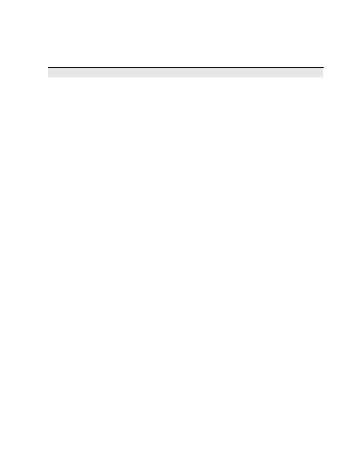
Required Equipment
Frequency Counte r Freq: 0.050 to 20 GHz
Accuracy:3ppm max
Frequency Counte r Freq: 0.050 to 26.5 GHz
Accuracy:3ppm max
Spectrum Analyzer Max Freq: 1.8 GHz RBW: 300 Hz 8591E A,T
Power Meter Accura cy : ±0.02 dB 436A, 437B, 438A
Power Sensor Freq: 0.050 to 20.05 GHz
Range: –30 to +20 dBm
Power Sensor Freq: 0.050 to 40 G Hz
Range: –30 to +20 dBm
Digital Voltmeter Resolution: 10 mV Any T
Oscilloscope Bandwidth: 100 MHz Any T
Printer Raster graphics capability Any P
Critical Specifications Recommended Model or
HP/Agilent Part Number
Test Instruments
5350B, 53150A P,A,T
5351B, 53151A P,A,T
E4418A (EPM-441A)
E4419A (EPM-442A)
8485A P,A,T
8487A P,A,T
Use
P,A,T
Calibration and Verification Kits
2.4 mm Calibration Kit No substitute 85056A P,A,T
2.4 mm Verification Kit No substitute 85057B P
3.5 mm Calibration Kit No substitute 85052B P,A,T
3.5 mm Verification Kit
7 mm Calibration Kit No substitute 85050B P,T
7 mm Ve rification Kit
Type-N Calibration Kit No substitut e 85054B P,T
Type-N Verification Kit
1
2
3
No substitute 85053B P
No substitute 85051B P
No substitute 85055A P
P - Performance Tests A - Adjustments T - Troubleshooting
1. Verification can only be done up to 26.5 GHz on the Agilent 8722ET/ES while using the 3.5
mm Verification Kit.
2. Verification can only be done up to 18 GHz, while using the 7mm Verification Kit.
3. Verification can only be done up to 18 GHz, while using the Type-N Verification Kit.
Service Guide 1-3

Service Equipment and Analyzer Options 8719ET/20ET/22ET
Service Test Equipment 8719E S/20ES/22ES
RF Network Analyzers
Required Equipment Critical Specificat ions Recommended Model or
HP/Agilent Part Number
Adapt ers and Loads
RF Load 3.5 mm(f), 50 ohm 00902-60004
(Part of 85052B)
RF Load 2.4 mm(f), 50 ohm 00901-60004
(Part of 85056A)
RF Short 3.5 mm (f) 85052-60007
(Part of 85052B)
RF Short 2.4mm (f) 85056-60021
(Part of 85056A)
RF Open 3.5 mm(f) 85052-60009
(Part of 85052B)
RF Open 2.4 mm(f) 85056-60023
(Part of 85056A)
RF Adapter 3.5 mm(f) to 3.5 mm(f) 85052-60012
(Part of 85052B)
RF Adapter 2.4 mm(f) to 2.4 mm(f) 85056-60006
(Part of 85056A)
RF Power Splitter 3.5 mm 11667B T
RF Power Splitter 2.4 mm 11667C T
Use
P
P
P
P
A
A
P,A
P,A
RF Fixed Attenuator 3.5 mm 8493C Opt. 010 A
RF Fixed Attenuator 2.4 mm 8490D Opt. 010 A
RF Adapter 2.4 mm (f) to Type-N (f) 11903B A
RF Adapter 3.5 mm (f) to Type-N (f) 1250-1745 (2 total) A
Cables
RF Cable BNC 50 ohm, 24 inch 8120-2582 A
RF Cable Type-N ( m) connectors, 50W,
24-inch
RF Cable Set 3.5 mm connectors 85131F P,A,T
RF Cable Set 7 mm connectors to 3.5 mm 85132F P
RF Cable Set 2.4 mm connectors 85133F P,A,T
Exten si o n Ca b l es SMB (f ) to BNC (m) (4 ft . le n g t h) 8120–5048 T
Extension Cables SMB (m) to SMB (f) 8120–5040 A,T
Coax Cable BNC (m) to BNC (m), 50W 10503A A
GPIB Cables 1 meter length 10833A A
P - Performance Tests A - Adjustments T - Troubleshooting
11500C (2 total) P,A
1-4 Service Guide
8719ET/20ET/22ET Service Equipment and Analyzer Options
8719ES/20ES/22ES Service Test Equipment
RF Network Analyzers
Required Equipment Critical Specifications Recommended Model or
HP/AgilentPart Number
Tools and Static Safety Par ts
Non-Metallic Adjust Tool 8830-0024 A
Tool Kit No substitute 08722-60018 P,A,T
Anti-Static Wrist Strap 9300-1367 A,T
Anti-Static Wrist Strap Cord 9300-0980 A,T
Static Control Table Ma t and
Earth Ground Wire
Floppy Disk one 3.5-inch formatted 1.44 MB N/A A
P - Performance Tests A - Adjustments T - Troubleshooting
9300-0797 A,T
Use
Service Guide 1-5
Service Equipment and Analyzer Options 8719ET/20ET/22ET
Principles of Microwave Connector Care 8719ES/20ES/22ES
RF Network Analyzers
Principles of Microwave Connector Care
Proper connector care and connection technique are critical for accurate and repeatable
measurements.
Refer to the calibration kit documentation for connector care infor mati on. Prior to making
connections to the network analyzer, carefully review the information about inspecting,
cleaning, and gauging connectors.
Practicing good connector care and connection technique extends the life of these devices.
In addition, you obtain the most accurate measurements.
For additional connector care instruction, contact your nearest Agilent Technologies sales
or service office about course numbers HP/Agilent 85050A+24A and HP/Agilent
85050A+24D.
See the following table for quick reference tips about connector care.
Table 1-1 Connector Care Quick Reference
Handling and Stor age
Do Keep connectors clean Do Not Touch mating-plane surfaces
Extend sleeve or connector nut Set connectors contact- end down
Use plastic end -c a ps du r i ng sto rag e
Visual Inspecti on
Do Inspect all connectors carefully Do Not Use a damaged connector - ever
Look for metal particles, scratches, and dents
Connector Cleaning
Do Try compressed air first Do Not Use any abrasi ve s
Use isopropyl alcohol Get liquid into plastic support beads
Clean connect or threads
Gauging Conne c tors
Do Clean and zero the gauge bef ore use Do Not Use an out-o f-spe c connec tor
Use the correct gauge type
Use correct end of calibration block
Gauge all connectors before first use
Making Connec tions
Do Align conne ct ors carefull y Do Not Apply bending force to connection
Make preliminary connection lightly Over tighten preliminary connection
Turn only the connec tor nut Twist or screw any connection
Use a torque wrench for final connect Tighten past torque wrench “break” point
1-6 Service Guide

8719ET/20ET/22ET Service Equipment and Analyzer Options
8719ES/20ES/22ES Analyzer Options
RF Network Analyzers
Analyzer Options
Option 1D5, High Stability Frequency Reference
Option 1D5 offers ±0.05 ppm temperature stability from 0 to 55 °C (referenced to 25 °C).
Option 004, Step Attenuator (ET Models)
This option adds a 55 dB step attenuator into the RF output path.
Option 007, Mechanical Transfer Switch (ES Models)
This option replaces the solid state transfer switch with a mechanical transfer switch,
providing the analyzer with greater power handling capability. Because the mechanical
transfer switch has less loss than the solid state transfer switch, the output power of an
Option 007 analyzer is 5 dB higher.
Option 010, Time Domain
This option allows the analyzer to display the time domain response of a network by
computing the inverse Fourier transform of the frequency domain response. The analyzer
shows the response of a test device as a function of time or distance. Displaying the
reflection coefficient of a network versus time determines the magnitude and location of
each discontinuity. Displaying the transmission coefficient of a network versus time
determines the characteristics of individual transmiss ion paths . Ti me domain operation
retains all accuracy inherent with the active error correction.
Option 012, Direct Access Receiver Configuration (ES Models)
This option provides front panel access to the A and B samplers. This allows direct access
to the sampler inputs for improved sensitivity in applicat ions s uc h as antenna tests, or for
the insertion of attenuators between the couplers and samplers. Direct access to the
B (A) sampler provides increased dynamic range in the forward (reverse) direction.
Service Guide 1-7

Service Equipment and Analyzer Options 8719ET/20ET/22ET
Analyzer Options 8719ES/20ES/22ES
RF Network Analyzers
Option 085, High Power System (ES Models)
This option is designed to permit the measurement of high power devices. With an
external power amplifier, this config ur ation will al low up to 20 Watts (+43 dBm) of output
at the test ports. The maximum test port input power is 1 Watt (+30 dBm) CW, but
jumpers on the front panel allow the insertion of high power attenuators or isolators. This
allows test device output levels up to the power limits of the inserted components.
Additionally, there is an external reference input that allows the external amplifier’s
frequency response and drift to be ratioed out, and there are internally controlled step
attenuators between the couplers and samplers to prevent overload. A network analyzer
with this option can be configured to operate as a normal instrument (with slightly
degraded output power level and accuracy) or as an instrument capable of making single
connection multiple measurements. Bias tees are not part of the signal separation
circuitry of the Option 085. Because of high output power, Option 085 is only available
with a mechanical transfer switch similar to Option 007. Option 085 also includes direct
access to the receiver (Option 012).
Option 089, Frequency Offset Mode (ES Models)
This option adds the ability to offset the source and receiver frequencies for frequency
translation measurements . This provides the analyzer with mixer measurement capabil ity.
It also provides a graphical setup that allows easy configuration of your frequency
translation measurement.
Option 400, Four-Sampler Test Set (ES Models)
This option reconfigures the analyzer’s test set to ratio out the characteristics of the test
port transfer switch, and to include a second reference channel that allows full accuracy
with a TRL measurement calibration.
NOTE The 8722ES option 400 is optimized to operate with a tes t port cable length of
one meter. It may be necessary to set up the 8722ES Option 400 in the step
sweep mode if you are operating the analyzer with test port cables or
fixturing with an electronic length greater than one meter.
Option 1CP, Rack Mount Flange Kit With Handles
Option 1CP is a rack mount kit containing a pair of flanges, with handles, and the
necessary hardware to mount the analyzer in an equipment rack wit h 482.6 mm
(19 inches) horizontal spacing.
Option 1CM, Rack Mount Flange Kit Without Handles
Option 1CM is a rack mount kit containing a pair of flanges, without handles, and the
necessary hardware to mount the analyzer in an equipment rack wit h 482.6 mm
(19 inches) horizontal spacing.
1-8 Service Guide

8719ET/20ET/22ET Service Equipment and Analyzer Options
8719ES/20ES/22ES Service and Support Options
RF Network Analyzers
Service and Support Options
The anal yz e r’s stan dard warranty is a three-year re tu rn to A gilent servic e war ranty.
The following service and support options are available at the time you purchase an
Agilent 8 719ET/ES, Agilent 8720ET/ES, or an Agilent 8722ET/ES network analyzer.
Option W01
This option converts the standard three-year return to Agilent Technologies service
warranty t o a one-year on-site service warranty. This option may not be available in all
areas.
Option W31
This option converts the standard three-year return to Agilent Technologies service
warranty t o a three-year on-site service warranty. This option may not be available in all
areas.
Option W50
This option adds two years to the standard three-year return to Agilent Technologies
warranty for a total of a five-year return to Agilent Technologies service warranty.
Option W51
This option converts the standard three-year return to Agilent Technologies service
warranty t o a fiv e-y ear on-site se rvice warrant y. This opt i on may not be available in all
areas.
Option W32
This option provides yearly return to Ag ilent Technologies for a commercial calibration for
a period of three years. The calibration provided is traceable to national standards.
Option W52
This option provides yearly return to Ag ilent Technologies for a commercial calibration for
a period of five years. The calibration provided is traceable to national standards.
Option W34
This option provides yearly return to Agilent Technologies for a Standards Compliant
Calibration for a period of three years. This type of calibration meets the ANSI/NCSL
Z540–1–1994 standard.
Service Guide 1-9

Service Equipment and Analyzer Options 8719ET/20ET/22ET
Service and Support Options 8719ES/20ES/22ES
RF Network Analyzers
Option W54
This option provides yearly return to Agilent Technologies for a Standards Compliant
Calibration for a period of five years. This type of calibration meets the ANSI/NCSL
Z540–1–1 994 standard.
NOTE If the previous servi ce and support optio ns were not purchas ed along with the
analyzer, there are many other repair and calibration options available from
Agilent Technologies’ support organization. These options cover a range of
on-site services and agreements with varying response times as well as
return to Agilent Technologies agreements and per-incident pricing. Contact
the nearest Agilent Technologies sales or service office for details. Refer to
Chapter 15 , “Safety and Regulatory Information.”
1-10 Service Guide

2 System Verification and
Performance Tests
2-1

System Verification and Per formance Tests 8719ET/20ET/22ET
Sections in This Chapter 8719ES/20ES/22ES
RF Network Analyzers
Sections in This Chapter
This chapter consists of five sections.
How to Test the Performance of Your Analyzer
• ANSI/NCSL Z540–1–1994 Verification‚ on page 2-3
• Non-AN S I/ NC SL Z540–1–1994 Verification‚ on page 2-3
• Instrum ent Verification C ycl e, on page 2-4
• ANSI/NCSL Z540–1–1994 Test Path Verification Flowchart, on page 2-4
• Non–ANSI/NCSL Z540–1–1994 Test Path Verification Flowchart, on page 2-5
Preliminary Tests
• Check the Temperature and Humidity, on page 2-6
• Clean and Gauge All Connectors, on page 2-7
• Perform the Internal Test, on page 2-7
• Procedure to Perform Operator’s Check, on page 2-8
• Check the Test Port Cables, on page 2-9
System Verification
• Equipment Initialization, on page 2-20
• Measurement Calibration, on page 2-22
• Verification Device Measurements, on page 2-25
• Interpreting the Verification Results, on page 2-31
Performance Tests
• Frequency Accuracy Performance Test, on page 2-34
• Level Accuracy Performance Test, on page 2-36
• Source Linearity Performance Test, on page 2-38
• Dynamic Range Performance Test, on page 2-42
Performance Test Records
• Performance Test Record, on page 2-46
2-2 Service Guide

8719ET/20ET/22ET System Ver ificati on and Performance T ests
8719ES/20ES/22ES How to Test the Performance of Your Analyzer
RF Network Analyzers
How to Test the Performance of Your Analyzer
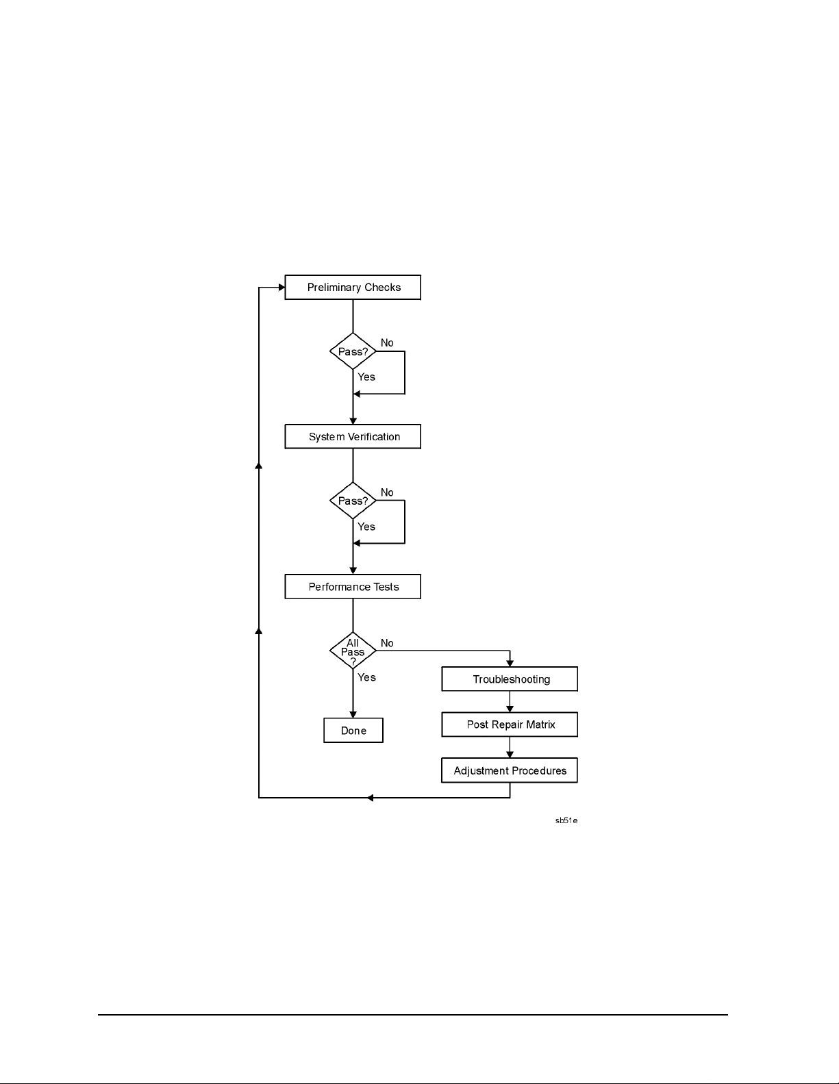
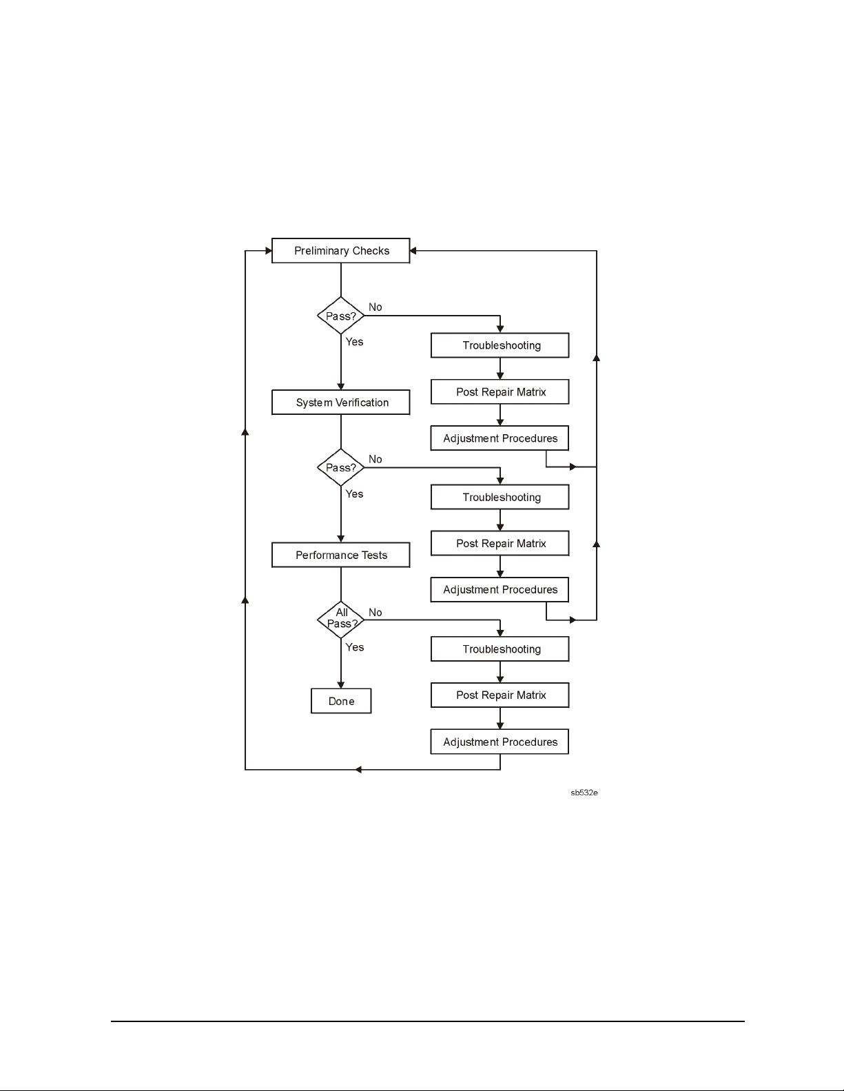
There are two different way s to verif y the perfor mance of your a nalyzer. One method meets
ANSI/NCSL Z540–1–1994 standards, and the other method does not. To determine which
type of verification you wish to perform, refer to the follo wing descr ipti ons and flow charts.
ANSI/NCSL Z540–1–1994 Verification
This type of veri f icat ion co nsis ts of c onduc ting the preliminary checks , system verifica tion,
and the performance tests w ithout stoppi ng to troubleshoot . Exceptions will only be made
in case of catastrophic fa ilure or ca ble connector damage . In order to obtain da ta of how the
analyzer was performing at the time of verification, these tests must be done even if you
are aware that the analyzer will not pass. Obtaining th e data ( s ystem veri fi c ation p r int out
and performance test record) at this point is necessary so that you will understand that
your measurements may not have been accurate. You must wait until after the
ANSI/NCSL Z540–1–1994 verification is complete before troubleshooting and repairing
any problems. After troubleshooting , co nsult Table 14-1 o n page 14-35 to find the
necessary adjustment procedures. Then repeat the system verification and performance
tests, generating a new set of data.
Non-ANSI/NCSL Z540–1–1994 Verification
This type of veri f icat ion co nsis ts of c onduc ting the preliminary checks , system verifica tion,
and perfor mance tests, but stoppin g at any point if the analyzer fails a test. You will
troubleshoot and repair the first problem encountered without continuing to other tests.
After troubleshooting, consult Table 1 4-1 on page 1 4-35 to find the necessary adjustment
procedures. Then repeat the system verification and performance tests. As the analyzer
passes the system verification and all the tests, you will print out the system verification
results and fill in the performance test record.
Service Guide 2-3
System Verification and Per formance Tests 8719ET/20ET/22ET
How to Test the Perf or mance of Your Analyzer 8719ES/20ES/22ES
RF Network Analyzers
Instrument Verification Cycle
The performance of the network analyzer should be verified at least once per year. The
following flowcharts illustrate the test path for both types of verifications.
Figure 2-1 ANSI/NCSL Z540–1–1994 Test Path Verification Flowchart
2-4 Service Guide
8719ET/20ET/22ET System Ver ificati on and Performance T ests
8719ES/20ES/22ES How to Test the Performance of Your Analyzer
RF Network Analyzers
Figure 2-2 Non–ANSI/NCSL Z540–1–1994 Test Path Verification Flowchart
Service Guide 2-5

System Verification and Per formance Tests 8719ET/20ET/22ET
Preliminary Tests 8719ES/20ES/22ES
RF Network Analyzers
Preliminary Te sts
CAUTION Use an antistatic work surface and wrist strap to lessen the chance of
electrostatic discharge.
Required Equipment and Tools
Equipment Description 8719/20 8722
Calibration Kit 85052B 85056A
RF Cable Set 85131F 85133F
Verification Kit 85053B 85057B
Check the Temperature and Humidity
1. Measure the temperature and humidity of the environment and record the values in
Table 2-14, “Performance Test Record for All Models,” on page 2-46. The performance is
specified at an ambient temperature of +23 ±3 °C. Therefore, the environmental
temperature must remain in the range of +20 °C to +26 °C. Once the measurement
calibration has been done, the ambient temperature must be held to range of ± 1 °C.
2. Open the calibration and verifica tio n kits a nd pla ce all the d evi c es on top of the foam so
they will reach room temperatur e. The temperature of the devices is important because
device dimensions and therefore the electrical chara ct eri stic s ch ange with temperature .
3. Switch on the power to the analyzer.
NOTE To achieve the maximum system stability, allow the analyzer to warm up for
at least 30 minutes.
2-6 Service Guide

8719ET/20ET/22ET System Ver ificati on and Performance T ests
PRESET : FACT ORY
SERVICE MENU
TESTS
INTERNAL TESTS
EXECUTE TEST
8719ES/20ES/22ES Preliminary Tests
RF Network Analyzers
Clean and Gauge All Connectors
CAUTION To prevent damage to the calibration kit and verification kit devices always
replace or repair any damaged connectors before proceeding with these tests.
NOTE Always use adapters when verifying a system with SMA connectors.
1. Visually inspect all the connectors f or any burr s, gold flakes, or places where the gold is
worn.
2. Clean all the connectors with alcohol and foam-ti pped sw a bs. Dry the connectors with a
dry foam-tipped swab.
3. Visually inspect the calibration block and the end of the connector gauge before any
measurements are made.
4. Gauge all devices, cables, and test port connectors . Ref er to the calibrat ion kit manuals
for the correct use of gauges.
Perform the Internal Test
This quick, automated internal test may save time by indicating an instrument fault
before doing the performance tests. The tests performed are described in
Chapter 10 , “Service Key Menus and Error Messages.”
NOTE To achieve the maximum system stability, allow the analyzer to warm up for
at least 30 minutes.
To run the analyzer internal test, press the following:
Preset
System
A PASS message will appear on the display if the instrument passes this test.
Preset
Service Guide 2-7

System Verification and Per formance Tests 8719ET/20ET/22ET
PRESET : FACT ORY
SERVICE MENU
TESTS
EXTERNAL TESTS
EXECUTE TEST
CONTI NUE
CONTI NUE
PRESET : FACT ORY
SERVICE MENU
TESTS
EXECUTE TEST
CONTI NUE
CONTI NUE
PRESET : FACT ORY
SERVICE MENU
TESTS
EXECUTE TEST
CONTI NUE
Preliminary Tests 8719ES/20ES/22ES
RF Network Analyzers
Procedure to Perform Operator’s Check
PORT 1 or REFLECTION port Check
1. Connect a short to PORT 1 (REFLECTION port on ET models).
2. Press the following:
Preset
System
Preset
• If the message PRESS[CONTI NUE] appears on the display during the test, that
particular attenuator setting check has failed. Press to check the
other attenuator settings .
• If the message FAIL appears on the analyzer display, the analyzer has failed the
PORT 1 operation check. Refer to the flow charts on page 2-4 and page 2-5.
• If the message DONE appears on the analyzer display, the analyzer has passed the
PORT 1 operation check.
PORT 2 Check (E S Mode ls)
3. Connect the short to PORT 2.
4. Press the following:
Preset
System
22 x1
Preset
• If the message PRESS[CONTI NUE] appears on the display during the test, that
particular attenuator setting check has failed. Press to check the
other attenuator settings .
• If the message FAIL appears on the analyzer display, the analyzer has failed the
PORT 2 operation check. Refer to the flow charts on page 2-4 and page 2-5.
• If the message DONE appears on the analyzer display, the analyzer has passed the
PORT 2 operation check.
Transmission Port Check (ET Models)
5. Connect an RF cable from the REFLECTION port to the TRANSMISSION port.
6. Press the following:
Preset
System
22 x1
2-8 Service Guide
Preset
 Loading...