


Reference Guide
Agilent Technologies
8719ET/20ET/22ET
8719ES/20ES/22ES
Network Analyzers
Part Number 08720- 90393
Printed in USA
June 2002
Supersedes February 2001
© Copy right 1999–2002
Agilent Technologies, Inc.

Notice
The information contained in this document is subject to change without notice.
Agilent Technologies makes no warranty of any kind with regard to this material,
including but not limited to, the implied warra nties of merchantability and fitness for a
particular purpose. Agilent Technologies shall not be l iable for errors contained herein or
for incidental or consequent ial damages in connect ion with the furnishing , performance, or
use of this material.
Certification
Agilent Technologies certifies that thi s produc t m et i ts p ub lis hed speci fi c ations a t the time
of shipment from the factory. Agilent Technologies further certifies that its calibration
measurements are traceable to the United States National Institute of Standards and
Technology, to the extent allowed by the Institute’s calibration facility, and to the
calibration faci lities of other International Standa rds Organization members.
Regulatory and Warranty Information
The regulatory and wa rranty information is located in the user’s guide.
Assistan ce
Product maintenance agreements and other customer assistance agreements are availa ble
for Agilent Technologies products. For any assistance, contact your nearest Agilent
Technologies sales or service office. See the user’s guide for the nearest office.
Safety Notes
The following safety notes are used throughout this manual. Familiarize yourself w ith
each of the notes and its meaning befor e operating this instrument. All perti nent safety
notes for using this product are located in the user’s guide.
WARNING Warning denotes a hazard. It calls attention to a procedure which, if
not correctly performed or adhered to, could result in injury or loss
of life. Do not proceed beyond a warning note until the indicated
conditions are fully understood and m et.
CAUTION Caution denotes a hazard. It calls attenti on to a procedure that, if not
correctly performed or adhered to , would result i n damage to or destruction of
the instrument. Do not p roceed beyond a caution sign until the indicated
conditions are ful ly understood and met.
ii

How to Use This Guide
Front-Pa nel Key
SOFTKEY
This guide uses the following conventions:
This represents a key physically located on the
instrument.
This represents a “softkey,” a key whose label is
determined by the instrument’s firm ware.
Screen Text This represents text displayed on the instrument’s screen.
iii

Documentation Map
The Installation an d Quick Start Guide pr ovides procedures for
installing, c onfiguring, and verifying the operation of the analyzer. It
also will help you fa m iliarize yourself with the basic operation of the
analyzer.
The User’s Guide shows how to make measurements, explains
commonly-used features, and tells you how to get the most
perform ance from yo u r an alyzer.
The Reference Guide provides refe ren ce informat ion, such as
specifications, menu maps, and key definitions.
The Programm er’s Guide provides general GPIB programming
informat ion, a comm and reference, and example prog rams. The
Programmer’s Guide contains a CD-ROM with example programs.
iv
The CD-ROM provides the Installa tio n and Qu ick Start Guide, the
User’s Guid e, the Referen ce Guide, and the Progra mmer’s Guid e in
PDF format for vie wing or prin t ing from a PC.
The Service Guide pr ovides information on calibrating,
troubleshooting, and servicing your analyzer . The Serv ic e Gu ide i s not
part of a standard shipm ent and is available only as Option 0BW, or
by ordering part number 08720-90397. A CD-ROM with the Service
Guide in PDF format is included for viewing or printing from a PC.

Contents
1. 8719/20/22ES Specif ications and Characteristics
Definitions . . . . . . . . . . . . . . . . . . . . . . . . . . . . . . . . . . . . . . . . . . . . . . . . . . . . . . . . . . . . . . . . .1-2
Specifications for Instruments with Multiple Options . . . . . . . . . . . . . . . . . . . . . . . . . . . . .1-2
Corrected System Performance (8719/20ES) . . . . . . . . . . . . . . . . . . . . . . . . . . . . . . . . . . . . . . 1-3
Corrected System Performance (8722ES). . . . . . . . . . . . . . . . . . . . . . . . . . . . . . . . . . . . . . . .1-14
Instrument Specifications . . . . . . . . . . . . . . . . . . . . . . . . . . . . . . . . . . . . . . . . . . . . . . . . . . . .1-24
Uncorrected Port Performance. . . . . . . . . . . . . . . . . . . . . . . . . . . . . . . . . . . . . . . . . . . . . . .1-24
Test Port Outpu t . . . . . . . . . . . . . . . . . . . . . . . . . . . . . . . . . . . . . . . . . . . . . . . . . . . . . . . . . .1-26
Test Port Input . . . . . . . . . . . . . . . . . . . . . . . . . . . . . . . . . . . . . . . . . . . . . . . . . . . . . . . . . . .1-33
General Information . . . . . . . . . . . . . . . . . . . . . . . . . . . . . . . . . . . . . . . . . . . . . . . . . . . . . . .1-40
Speed Parameters . . . . . . . . . . . . . . . . . . . . . . . . . . . . . . . . . . . . . . . . . . . . . . . . . . . . . . . 1-46
Power Meter Calibration Accuracy. . . . . . . . . . . . . . . . . . . . . . . . . . . . . . . . . . . . . . . . . .1-49
2. 8719/20/22ET Specifications and Characteristics
Definitions . . . . . . . . . . . . . . . . . . . . . . . . . . . . . . . . . . . . . . . . . . . . . . . . . . . . . . . . . . . . . . . . .2-2
Corrected System Performance (8719/20ET) . . . . . . . . . . . . . . . . . . . . . . . . . . . . . . . . . . . . . .2-3
Corrected System Performance (8722ET). . . . . . . . . . . . . . . . . . . . . . . . . . . . . . . . . . . . . . . . .2-7
Instrument Specifications . . . . . . . . . . . . . . . . . . . . . . . . . . . . . . . . . . . . . . . . . . . . . . . . . . . .2-10
Uncorrected Port Performance. . . . . . . . . . . . . . . . . . . . . . . . . . . . . . . . . . . . . . . . . . . . . . .2-10
Test Port Outpu t . . . . . . . . . . . . . . . . . . . . . . . . . . . . . . . . . . . . . . . . . . . . . . . . . . . . . . . . . .2-12
Test Port Input . . . . . . . . . . . . . . . . . . . . . . . . . . . . . . . . . . . . . . . . . . . . . . . . . . . . . . . . . . .2-18
General Information . . . . . . . . . . . . . . . . . . . . . . . . . . . . . . . . . . . . . . . . . . . . . . . . . . . . . . .2-28
Speed Parameters . . . . . . . . . . . . . . . . . . . . . . . . . . . . . . . . . . . . . . . . . . . . . . . . . . . . . . . 2-34
3. Front/Rear Panel
Front Panel Features . . . . . . . . . . . . . . . . . . . . . . . . . . . . . . . . . . . . . . . . . . . . . . . . . . . . . . . .3-2
Analyzer Display . . . . . . . . . . . . . . . . . . . . . . . . . . . . . . . . . . . . . . . . . . . . . . . . . . . . . . . . . . . .3-5
Rear Pa nel Features and Connectors . . . . . . . . . . . . . . . . . . . . . . . . . . . . . . . . . . . . . . . . . . . .3-9
4. Menu Maps
Menu Maps. . . . . . . . . . . . . . . . . . . . . . . . . . . . . . . . . . . . . . . . . . . . . . . . . . . . . . . . . . . . . . . . .4-2
5. Hardkey/Softkey Refere nce
Key Reference. . . . . . . . . . . . . . . . . . . . . . . . . . . . . . . . . . . . . . . . . . . . . . . . . . . . . . . . . . . . . . .5-2
Where to Look for More Information . . . . . . . . . . . . . . . . . . . . . . . . . . . . . . . . . . . . . . . . . . . .5-3
Guide Terms and Conventions . . . . . . . . . . . . . . . . . . . . . . . . . . . . . . . . . . . . . . . . . . . . . . . . .5-3
Analyzer Fun ctions . . . . . . . . . . . . . . . . . . . . . . . . . . . . . . . . . . . . . . . . . . . . . . . . . . . . . . . . . .5-4
6. Error Mes sages
Error Messages . . . . . . . . . . . . . . . . . . . . . . . . . . . . . . . . . . . . . . . . . . . . . . . . . . . . . . . . . . . . . .6-2
Error Messages in Alph abetical Order . . . . . . . . . . . . . . . . . . . . . . . . . . . . . . . . . . . . . . . . . . .6-3
Error Messages in Numerical Order. . . . . . . . . . . . . . . . . . . . . . . . . . . . . . . . . . . . . . . . . . . .6-26
7. Options and Accessories
Using This Ch apter . . . . . . . . . . . . . . . . . . . . . . . . . . . . . . . . . . . . . . . . . . . . . . . . . . . . . . . . . .7-2
Analyzer Opt ions Available . . . . . . . . . . . . . . . . . . . . . . . . . . . . . . . . . . . . . . . . . . . . . . . . . . .7-3
Option 1D5, High Stability Frequ ency Refe ren ce . . . . . . . . . . . . . . . . . . . . . . . . . . . . . . . .7-3
v

Contents
Option 004, Source Attenuat or (ET On ly) . . . . . . . . . . . . . . . . . . . . . . . . . . . . . . . . . . . . . .7-3
Option 007, Mechanical Tran sfer Sw itch (ES Only) . . . . . . . . . . . . . . . . . . . . . . . . . . . . . . 7-3
Option 010, Time Domain . . . . . . . . . . . . . . . . . . . . . . . . . . . . . . . . . . . . . . . . . . . . . . . . . . . 7-3
Option 012, Direct Access Receiver Configur ation (ES Onl y) . . . . . . . . . . . . . . . . . . . . . . . 7-3
Option 085, High Power System (ES Only) . . . . . . . . . . . . . . . . . . . . . . . . . . . . . . . . . . . . . 7-3
Option 089, Frequency Offset Mode (ES Only). . . . . . . . . . . . . . . . . . . . . . . . . . . . . . . . . . . 7-4
Option 400, Four-Sampler Test Set (ES Only) . . . . . . . . . . . . . . . . . . . . . . . . . . . . . . . . . . . 7-4
Option 1CM, Rack Mount Flange Ki t Without Handl es . . . . . . . . . . . . . . . . . . . . . . . . . . . 7-4
Option 1CP, Rack Mount Flange Kit With Handles . . . . . . . . . . . . . . . . . . . . . . . . . . . . . . 7-4
Service an d Support Options . . . . . . . . . . . . . . . . . . . . . . . . . . . . . . . . . . . . . . . . . . . . . . . . 7-4
Accessories Available . . . . . . . . . . . . . . . . . . . . . . . . . . . . . . . . . . . . . . . . . . . . . . . . . . . . . . . . 7-5
Measurement Accessories . . . . . . . . . . . . . . . . . . . . . . . . . . . . . . . . . . . . . . . . . . . . . . . . . . .7-5
Test-Port Cables: 3.5-mm . . . . . . . . . . . . . . . . . . . . . . . . . . . . . . . . . . . . . . . . . . . . . . . . .7-5
Test-Port Cables: 7mm . . . . . . . . . . . . . . . . . . . . . . . . . . . . . . . . . . . . . . . . . . . . . . . . . . . 7-6
Calibration Kits . . . . . . . . . . . . . . . . . . . . . . . . . . . . . . . . . . . . . . . . . . . . . . . . . . . . . . . . . 7-6
RF electronic calibration (ECal) modules and PC software . . . . . . . . . . . . . . . . . . . . . . . 7-8
Verification Kit . . . . . . . . . . . . . . . . . . . . . . . . . . . . . . . . . . . . . . . . . . . . . . . . . . . . . . . . . 7-1 0
Adapters . . . . . . . . . . . . . . . . . . . . . . . . . . . . . . . . . . . . . . . . . . . . . . . . . . . . . . . . . . . . . . 7-1 1
Tes t Configuration Accessories . . . . . . . . . . . . . . . . . . . . . . . . . . . . . . . . . . . . . . . . . . . . . .7-12
Power Meters . . . . . . . . . . . . . . . . . . . . . . . . . . . . . . . . . . . . . . . . . . . . . . . . . . . . . . . . . .7-12
Power Sensors. . . . . . . . . . . . . . . . . . . . . . . . . . . . . . . . . . . . . . . . . . . . . . . . . . . . . . . . . .7-12
Couplers . . . . . . . . . . . . . . . . . . . . . . . . . . . . . . . . . . . . . . . . . . . . . . . . . . . . . . . . . . . . . . 7-12
Keyboard Template . . . . . . . . . . . . . . . . . . . . . . . . . . . . . . . . . . . . . . . . . . . . . . . . . . . . . . .7-13
8. Preset State and Memory Allocation
Preset State . . . . . . . . . . . . . . . . . . . . . . . . . . . . . . . . . . . . . . . . . . . . . . . . . . . . . . . . . . . . . . . . 8-2
Memory Allocation. . . . . . . . . . . . . . . . . . . . . . . . . . . . . . . . . . . . . . . . . . . . . . . . . . . . . . . . . . 8 - 1 3
Types of Memory and Data Storage . . . . . . . . . . . . . . . . . . . . . . . . . . . . . . . . . . . . . . . . . . 8-13
Volatile Memory . . . . . . . . . . . . . . . . . . . . . . . . . . . . . . . . . . . . . . . . . . . . . . . . . . . . . . . .8-13
Non-Volatile Memory . . . . . . . . . . . . . . . . . . . . . . . . . . . . . . . . . . . . . . . . . . . . . . . . . . . . 8-13
Determining Memory Requirements. . . . . . . . . . . . . . . . . . . . . . . . . . . . . . . . . . . . . . . . . .8-15
Storing Data to Disk . . . . . . . . . . . . . . . . . . . . . . . . . . . . . . . . . . . . . . . . . . . . . . . . . . . . . .8-17
Conserving Memory . . . . . . . . . . . . . . . . . . . . . . . . . . . . . . . . . . . . . . . . . . . . . . . . . . . . . . 8-19
Using Saved Calibration Sets . . . . . . . . . . . . . . . . . . . . . . . . . . . . . . . . . . . . . . . . . . . . . . .8-19
Clearing Memory . . . . . . . . . . . . . . . . . . . . . . . . . . . . . . . . . . . . . . . . . . . . . . . . . . . . . . . . .8-20
9. Understanding the CITIfile Data Format
Using This Chapter . . . . . . . . . . . . . . . . . . . . . . . . . . . . . . . . . . . . . . . . . . . . . . . . . . . . . . . . . . 9-2
The CITIfile Data Format. . . . . . . . . . . . . . . . . . . . . . . . . . . . . . . . . . . . . . . . . . . . . . . . . . . . .9-3
Description and Overview . . . . . . . . . . . . . . . . . . . . . . . . . . . . . . . . . . . . . . . . . . . . . . . . . . .9-3
Data Formats . . . . . . . . . . . . . . . . . . . . . . . . . . . . . . . . . . . . . . . . . . . . . . . . . . . . . . . . . . . 9-3
File and Operating System Formats . . . . . . . . . . . . . . . . . . . . . . . . . . . . . . . . . . . . . . . . . 9-3
Definition of CITIfile Terms . . . . . . . . . . . . . . . . . . . . . . . . . . . . . . . . . . . . . . . . . . . . . . . . . 9-3
A CITIfile Package . . . . . . . . . . . . . . . . . . . . . . . . . . . . . . . . . . . . . . . . . . . . . . . . . . . . . . .9-4
The CITIfile Header . . . . . . . . . . . . . . . . . . . . . . . . . . . . . . . . . . . . . . . . . . . . . . . . . . . . . . 9-4
An Array of Data . . . . . . . . . . . . . . . . . . . . . . . . . . . . . . . . . . . . . . . . . . . . . . . . . . . . . . . . .9-4
CITIfile K eyword . . . . . . . . . . . . . . . . . . . . . . . . . . . . . . . . . . . . . . . . . . . . . . . . . . . . . . . .9-5
CITIfile Ex amples . . . . . . . . . . . . . . . . . . . . . . . . . . . . . . . . . . . . . . . . . . . . . . . . . . . . . . . . . 9-5
vi

Contents
Example 2, An 8510 Display Memory File. . . . . . . . . . . . . . . . . . . . . . . . . . . . . . . . . . . . .9-5
Example 3, 8510 Data file. . . . . . . . . . . . . . . . . . . . . . . . . . . . . . . . . . . . . . . . . . . . . . . . . .9-5
Example 4, 8510 3-Term Frequency List Cal Set File. . . . . . . . . . . . . . . . . . . . . . . . . . . .9-6
CITIfile K eywords . . . . . . . . . . . . . . . . . . . . . . . . . . . . . . . . . . . . . . . . . . . . . . . . . . . . . . . . . . .9-8
Useful Calc ulations . . . . . . . . . . . . . . . . . . . . . . . . . . . . . . . . . . . . . . . . . . . . . . . . . . . . . . . . .9-11
Computing Frequency Points . . . . . . . . . . . . . . . . . . . . . . . . . . . . . . . . . . . . . . . . . . . . . . . .9-11
Expressing CITIfile Data in Other Data Formats. . . . . . . . . . . . . . . . . . . . . . . . . . . . . . . .9-12
Example Data . . . . . . . . . . . . . . . . . . . . . . . . . . . . . . . . . . . . . . . . . . . . . . . . . . . . . . . . . .9-13
10. Determining System Measurement Uncertainties
Introduction . . . . . . . . . . . . . . . . . . . . . . . . . . . . . . . . . . . . . . . . . . . . . . . . . . . . . . . . . . . . . . .10- 2
Sources of Measurement Errors . . . . . . . . . . . . . . . . . . . . . . . . . . . . . . . . . . . . . . . . . . . . . . .10-3
Sources of Systematic Errors . . . . . . . . . . . . . . . . . . . . . . . . . . . . . . . . . . . . . . . . . . . . . . . .10-3
Sources of Random Errors . . . . . . . . . . . . . . . . . . . . . . . . . . . . . . . . . . . . . . . . . . . . . . . . . .10-4
Det ermining Exp ected Syste m Perform a nce . . . . . . . . . . . . . . . . . . . . . . . . . . . . . . . . . . . . .10 -5
Determini ng Cable Stability Terms (C
Measurement Uncertainty Equations. . . . . . . . . . . . . . . . . . . . . . . . . . . . . . . . . . . . . . . . . . .10-8
Forward Reflection Uncertainty . . . . . . . . . . . . . . . . . . . . . . . . . . . . . . . . . . . . . . . . . . . . . .10-8
Forward Transmission Uncertainty. . . . . . . . . . . . . . . . . . . . . . . . . . . . . . . . . . . . . . . . . . .10-9
Reverse Reflection Uncertainty . . . . . . . . . . . . . . . . . . . . . . . . . . . . . . . . . . . . . . . . . . . . .10-10
Reverse Transmission Uncertainty . . . . . . . . . . . . . . . . . . . . . . . . . . . . . . . . . . . . . . . . . .10-11
, CR2, C
R1
TM1
, C
TM2
, C
TP1
, C
). . . . . . . . . . . . . . .10-6
TP2
vii

Contents
viii

1 8719/20/22ES
Specifications and Characteristics
1-1

8719/20/22ES Specifications and Character istics
Definitions
Definitions
All specifications and characteristics apply over a 23 °C ±3 °C range (unless otherwise
stated) and 1/2 hour after the instrument has been turned on.
Specification (spec.): Warranted performance. Specifications include gua rdbands to
account for the expected statistical performance distribution, measurement uncertainties,
and changes in performance due to environmental conditions.
Characte ristic (char.): A performance parameter that the prod uct is expected to meet
before it leaves the factory, but that is not verified in the field and is not covered by the
product warranty. A characteristic includes the sa m e guardbands as a specification.
Typical (typ.): Expected performance of an average unit which does not include
guardbands. It is not covered by the product wa rranty.
Nominal (nom.): A general, descriptive term that d oes not imply a level of performance. It
is not covered by the product warranty.
Calibration : The process of measuring know n standards from a calibration kit to
characterize a netw ork analyzer’s systematic (repeatable) errors.
Corrected (residual) Performance: Indicates performance after error correction
(calibration). It is determined by the quality of ca libration standards and how well
“known” they are, plus system repeatability, stability, and noise.
Uncorrec ted (raw) Performance: Indicates instrument performance without error
correction. The unc orrected performance affects the stability of a calib ration.
Standard: When referring to the analyzer, this includes all options unless noted otherwise.
Specifications for Instruments with Multiple Options
For instruments with any or all of the following options, standard instrument
specifications apply:
• Option 400
• Option 089
• Option 012 (except where noted)
For instruments with Option 089 and Option 007, Option 007 specifications apply.
For instruments with Option 089 and Option 085, Option 085 measurement uncertainties
apply, Option 089 R input specifications apply, and all other standard instrument
specifications apply .
For preconfigured analyzers, standard instrument specifications apply, except for
frequency stability ; Option 1D5 specifications apply.
1-2

8719/20/22ES Specifications and Characteristics
Corrected System Performance (8719/20ES)
Corrected System Performance (8719/20ES)
The specifications in this sec tion apply for meas urements made using 10 Hz IF bandwidth,
no averaging, and at an environmental temperature of 23 ±3 °C, with less than 1 °C
deviation from the calibration temperature. Assumes that an isolation calibration was
performed with an averaging factor of 8.
Table 1-1 System Dynamic Range, All Device Connector Types
8719/20ES, All Cal Kits, All Cables, 10 Hz IF BW
Description Specificati on Supplemental
Information
System Transmissio n Dynamic Range
8719/20ES (Standard)
50 MHz to 840 MHz 77 dB
840 MHz to 8 GHz 100 dB
8 GHz to 20 GHz 100 dB
8719/20ES (Option 007)
50 MHz to 840 MHz 82 dB
840 MHz to 20 GHz 105 dB
8719/20ES (Option 012 wi th te st set byp as se d)
50 MHz to 500 MHz 115 dB, typ.
500 MHz to 2 GHz 115 dB, typ.
2 GHz to 8 GHz 115 dB, typ.
8 GHz to 13.5 GHz 113 dB, typ.
13.5 GHz to 20 GHz 113 dB, typ.
a
a
b
a. The Syste m Tran sm ission Dynamic Ran ge is calc ulated as the difference
between the receiver noise floor and the lesser of either: the source maximum
output or the receiv er maximu m inpu t. The receiver noise floor is speci f i ed as 3
standard deviations above the mean of the linear magnitude noise floor trace
over the specified frequency band.
b. The System Transmission Dyn amic Range is calculated as th e diffe renc e
between the receiver noise floor and the lesser of either: the source maximum
output or the receiver maximum input. The rece i ver nois e floo r is specif i ed as
the me a n of the linear magnitude noise floor trace over the specified frequency
band.
1-3

8719/20/22ES Specifications and Character istics
Corrected System Performance (8719/20ES)
Table 1-2 System D ynamic Range, All Device Connector Types
8722ES, All Cal Kits, All Cables, 10 Hz IF BW
Description Specification Supplemental
Information
System Transmission Dynamic Range
8722ES (Standard)
50 MHz to 840 MHz 67 dB
840 MHz to 8 GHz 93 dB
8 GHz to 20 GHz 91 dB
20 GHz to 40 GHz
8722ES (Option 007)
50 MHz to 840 MHz 72 dB
840 MHz to 8 GHz 98 dB
8 GHz to 20 GHz 96 dB
20 GHz to 40 GHz
8722ES (Option 012 with test set bypassed)
50 MHz to 500 MHz 115 dB, typ.
50 Hz to 8 GHz 115 dB, typ.
8 GHz to 20 GHz 113 dB, typ.
20 GHz to 40 GHz 108 dB, typ.
a
b
80 dB
a
b
85 dB
c
a. The System Transmis sion Dynamic Range is ca lculated as the difference
between the receiver noise floor and the les ser of eithe r: the source maximum
output or the receiver maxi mum input . Th e rec ei ve r no ise fl oor is s peci fi ed as 3
standard deviations above the mean of the linear magnitude noise floor trace
over the specified frequency band.
b. 3 dB less for Option 085 or Optio n 012 .
c. The System Tra nsmission Dynamic Range is calculated as the di fference
between the receiver noise floor and the les ser of eithe r: the source maximum
output or the receiver maximum input. The receiver noise floor is specified as
the mean of th e linear magnitude noise floor trace over the specified frequency
band.
1-4

8719/20/22ES Specifications and Characteristics
Corrected System Performance (8719/20ES)
Table 1-3 3.5-mm Device Connector T ype
Network Analyzer: 8719ES/20ES, Standard
Calibration Kit: 85052D (3.5-mm, 50 Ω)
Cables: 85131F
Calibration: Full 2-Port
IF BW = 10 H z, Avg off, Temp = 23 ± 3 °C with < 1 °C deviation from cal temp, Isol cal with avg = 8
Description Specification
50 to 500 MHz 0.5 to 2 GHz 2 to 8 GHz 8 to 20 GHz
Directivity (dB) 42 42 38 36
Source Match (dB) 37 37 31 28
Load Match (dB) 42 42 38 36
Refl. Tracking
Magnitude (dB) ±(0.006 + .02/°C) ±(0.006 + .03/°C) ±(0.006 + .03/°C) ±(0.009 + .04/°C)
Phase (deg) ±(0.040 + 0.1/°C) ±(0.040 + 0.1/°C) ±(0.040 + 0.3/°C) ±(0.059 + 0.5/°C)
Trans. Tracking
Magnitude (dB) ±(0.028 + .02/°C) ±(0.03 + .03/°C) ±(0.096 + .03/°C) ±(0.158 + .04/°C)
Phase (deg) ±(0.185 + 0.1/°C) ±(0.198 + 0.1/°C) ±(0.634 + 0.3/°C) ±(1.04 + 0.5/°C)
Transmis sion Uncertainty ( Specification)
Reflection Un ce rtainty (Specifi cat ion)
1-5

8719/20/22ES Specifications and Character istics
Corrected System Performance (8719/20ES)
Tab le 1-4 3.5-mm D evice Con nec tor Typ e
Network Analyzer: 8719ES/20ES, Standard
Calibration Kit: 85052B (3.5-mm, 50 Ω)
Cables: 85131F
Calibration: Full 2-Port
IF BW = 10 Hz, Avg off, Temp = 23 ± 3 °C with < 1 °C deviation from cal temp, Isol cal with avg = 8
Description Specification
50 to 500 MHz 0.5 to 2 GHz 2 to 8 GHz 8 to 20 GHz
Directivity (dB) 48 48 44 44
Source Match (dB) 40 40 33 31
Load Match (dB) 48 48 44 44
Refl. Tracking
Magnitude (dB) ±(0.006 + .02/°C) ±(0.006 + .03/°C) ±(0.006 + .03/°C) ±(0.008 + .04/°C)
Phase (deg) ±(0.040 + 0.1/°C) ±(0.040 + 0.1/°C) ±(0.040 + 0.3/°C) ±(0.053 + 0.5/°C)
Trans. Tracking
Magnitude (dB) ±(0.017 + .02/°C) ±(0.018 + .03/°C) ±(0.066 + .03/°C) ±(0.099 + .04/°C)
Phase (deg) ±(0.112 + 0.1/°C) ±(0.119 + 0.1/°C) ±(0.436 + 0.3/°C) ±(0.653 + 0.5/°C)
Transmission Uncertainty (Specification)
Reflection Uncertainty ( Specification)
1-6

8719/20/22ES Specifications and Characteristics
Corrected System Performance (8719/20ES)
Tab le 1-5 3.5-mm Device Connector Type
Network Analyzer: 8719ES/20ES, Option 400
Calibration Kit: 85052C (3.5-mm, 50 Ω)
Cables: 85131F
Calibration: T RL
IF BW = 10 Hz, Avg off, Temp = 23 ± 3 °C with < 1 °C deviation from cal temp, Isol cal with avg = 8
Description Specification
50 to 500 MHz 0.5 to 2 GHz 2 to 8 GHz 8 to 20 GHz
Directivity (dB) 48 48 50 50
Source Match (dB) 40 40 50 50
Load Match (dB) 48 48 50 50
Refl. Tracking
Magnitude (dB) ±(0.006 + .02/°C) ±(0.006 + .03/°C) ±(0.005 + .03/°C) ±(0.005 + .04/°C)
Phase (deg) ±(0.040 + 0.1/°C) ±(0.040 + 0.1/°C) ±(0. 033 + 0.3/°C) ±(0.033 + 0.5/°C)
Trans. Tracking
Magnitude (dB) ±(0.013 + .02/°C) ±(0.017 + .03/°C) ±(0.016 + .03/°C) ±(0.019 + .04/°C)
Phase (deg) ±(0.086 + 0.1/°C) ±(0.112 + 0.1/°C) ±(0. 107 + 0.3/°C) ±(0.125 + 0.5/°C)
Transmis sion Uncertainty ( Specification)
Reflection Un ce rtainty (Specifi cat ion)
1-7

8719/20/22ES Specifications and Character istics
Corrected System Performance (8719/20ES)
Tab le 1-6 3.5-mm D evice Con nec tor Typ e
Network Analyzer: 8719ES/20ES, Op tion 007
Calibration Kit: 85052B (3.5-mm with Sliding Loads, 50 Ω)
Cables: 85132F
Calibration: Full 2-Port
IF BW = 10 Hz, Avg off, Temp = 23 ± 3 °C with < 1 °C deviation from cal temp, Isol cal with avg = 8
Description Specification
0.05 to 0.5 GHz 0.5 to 2 GHz 2 t0 8GHz 8 to 20 GHz
Directivity (dB) 48 48 44 44
Source Match (dB) 40 39 32 30
Load Match (dB) 48 45 38 37
Refl. Tracking
Magnitude (dB) ±(0.006 + .02/°C) ±(0.010 + .03/°C) ±(0.030 + .03/°C) ±(0.031 + .04/°C)
Phase (deg) ±(0.040 + 0.1/°C) ±(0.0 66 + 0.1/°C) ±(0. 198 + 0.3/°C) ±(0.205 + 0.5/°C)
Trans. Tracking
Magnitude (dB) ±(0.011 + .02/°C) ±(0.016 + .03/°C) ±(0.066 + .03/°C) ±(0.108 + .04/°C)
Phase (deg) ±(0.073 + 0.1/°C) ±(0.1 06 + 0.1/°C) ±(0. 436 + 0.3/°C) ±(0.713 + 0.5/°C)
Transmission Uncertainty (Specification)
Reflection Uncertainty ( Specification)
1-8

8719/20/22ES Specifications and Characteristics
Corrected System Performance (8719/20ES)
Tab le 1-7 3.5-mm Device Connector Type
Network Analyzer: 8719ES/20ES, Option 007
Calibration Kit: 85052D (3.5-mm 50 Ω)
Cables: 85132F
Calibration: Full 2-Port
IF BW = 10 Hz, Avg off, Temp = 23 ± 3 °C with < 1 °C deviation from cal temp, Isol cal with avg = 8
Description Specification
0.05 to 0.5 GHz 0.5 to 2 GHz 2 t0 8GHz 8 to 20 GHz
Directivity (dB) 42 42 38 36
Source Match (dB) 37 37 30 28
Load Match (dB) 42 41 36 34
Refl. Tracking
Magnitude (dB) ±(0.006 + .02/°C) ±(0.010 + .03/°C) ±(0.030 + .03/°C) ±(0.031 + .04/°C)
Phase (deg) ±(0.038 + 0.1/°C) ±(0.069 + 0.1/°C) ±(0.200 + 0.3/°C) ±(0.205 + 0.5/°C)
Trans. Tracking
Magnitude (dB) ±(0.018 + .02/°C) ±(0.019 + .03/°C) ±(0.080 + .03/°C) ±(0.141 + .04/°C)
Phase (deg) ±(0.118 + 0.1/°C) ±(0.123 + 0.1/°C) ±(0.531 + 0.3/°C) ±(0.928 + 0.5/°C)
Transmis sion Uncertainty ( Specification)
Reflection Un ce rtainty (Specifi cat ion)
1-9

8719/20/22ES Specifications and Character istics
Corrected System Performance (8719/20ES)
Table 1-8 7-mm Device Connector Type
Network Analyzer: 8719ES/20ES, Standard
Calibration Kit: 85050B (7-mm, 50 Ω)
Cables: 85132F
Calibration: Full 2-Port
IF BW = 10 Hz, Avg off, Temp = 23 ± 3 °C with < 1 °C deviation from cal temp, Isol cal with avg = 8
Description Specification
50 to 500 MHz 0.5 to 2 GHz 2 to 8 GHz 8 to 18 GHz
Directivity (dB) 52 52 52 52
Source Match (dB) 48 48 44 41
Load Match (dB) 51 51 51 51
Refl. Tracking
Magnitude (dB) ±(0.006 + .02/°C) ±(0.006 + .03/°C) ±(0.017 + .03/°C) ±(0.047 + .04/°C)
Phase (deg) ±(0.040 + 0.1/°C) ±(0.0 40 + 0.1/°C) ±(0.112 + 0.3/°C) ±(0.310 + 0.5/°C)
Trans. Tracking
Magnitude (dB) ±(0.01 + .02/°C) ±(0.011 + .03/°C) ±(0.022 + .03/°C) ±(0.034 + .04/°C)
Phase (deg) ±(0.066 + 0.1/°C) ±(0.0 73 + 0.1/°C) ±(0.145 + 0.3/°C) ±(0.224 + 0.5/°C)
Transmission Uncertainty (Specification)
Reflection Uncertainty ( Specification)
1-10

8719/20/22ES Specifications and Characteristics
Corrected System Performance (8719/20ES)
Tab le 1-9 7-mm Device Connector Type
Network Analyzer: 8719ES/20ES, Option 400
Calibration Kit: 85050C (7-mm, 50 Ω)
Cables: 85132F
Calibration: T RL
IF BW = 10 Hz, Avg off, Temp = 23 ± 3 °C with < 1 °C deviation from cal temp, Isol cal with avg = 8
Description Specification
50 to 500 MHz 0.5 to 2 GHz 2 to 8 GHz 8 to 18 GHz
Directivity (dB) 52 52 60 60
Source Match (dB) 48 48 57 57
Load Match (dB) 51 51 57 57
Refl. Tracking
Magnitude (dB) ±(0.006 + .02/°C) ±(0.006 + .03/°C) ±(0.005 + .03/°C) ±(0.005 + .04/°C)
Phase (deg) ±(0.040 + 0.1/°C) ±(0.040 + 0.1/°C) ±(0. 033 + 0.3/°C) ±(0.33 + 0.5/°C)
Trans. Tracking
Magnitude (dB) ±(0.008 + .02/°C) ±(0.009 + .03/°C) ±(0.008 + .03/°C) ±(0.009 + .04/°C)
Phase (deg) ±(0.053 + 0.1/°C) ±(0.059 + 0.1/°C) ±(0. 055 + 0.3/°C) ±(0.059 + 0.5/°C)
Transmis sion Uncertainty ( Specification)
Reflection Un ce rtainty (Specifi cat ion)
1-11

8719/20/22ES Specifications and Character istics
Corrected System Performance (8719/20ES)
Table 1-10 Type-N Device Connector Type
Network Analyzer: 8719ES/20ES, Standard
Calibration Kit: 85054D (Type-N, 50 Ω)
Cables: 85132F
Calibration: Full 2-Port
IF BW = 10 Hz, Avg off, Temp = 23 ± 3 °C with < 1 °C deviation from cal temp, Isol cal with avg = 8
Description Specification
50 to 500 MHz 0.5 to 2 GHz 2 to 8 GHz 8 to 18 GHz
Directivity (dB) 40 40 36 34
Source Match (dB) 38 38 33 29
Load Match (dB) 40 40 36 34
Refl. Tracking
Magnitude (dB) ±(0.006 + .02/°C) ±(0.006 + .03/°C) ±(0.009 + .03/°C) ±(0.027 + .04/°C)
Phase (deg) ±(0.040 + 0.1°C) ±(0.040 + 0.1/°C) ±(0.059 + .30/°C) ±(0.178 + 0.5/°C)
Trans. Tracking
Magnitude (dB) ±(0.031 + .02/°C) ±(0.033 + .03/°C) ±(0.094 + .03/°C) ±(0.168 + .04/°C)
Phase ±(0.205 + 0.1/°C) ±(0.218 + 0.1/°C) ±(0.620 + 0.3/°C) ±(1.109 + 0.5/°C)
Transmission Uncertainty (Specification)
Reflection Uncertainty ( Specification)
1-12

8719/20/22ES Specifications and Characteristics
Corrected System Performance (8719/20ES)
Table 1-11 Type-N Device Connector Type
Network Analyzer: 8719ES/20ES, Standard
Calibration Kit: 85054B (Type-N, 50 Ω)
Cables: 85132F
Calibration: Full 2-Port
IF BW = 10 Hz, Avg off, Temp = 23 ± 3 °C with < 1 °C deviation from cal temp, Isol cal with avg = 8
Description Specification
50 to 500 MHz 0.5 to 2 GHz 2 to 8 GHz 8 to 18 GHz
Directivity (dB) 48 48 42 42
Source Match (dB) 45 45 36 32
Load Match (dB) 48 48 42 42
Refl. Tracking
Magnitude (dB) ±(0.005 + .02/°C) ±(0.005 + .03/°C) ±(0.006 + .03/°C) ±(0.015 + .04/°C)
Phase (deg) ±(0.033 + 0.1/°C) ±(0.033 + 0.1/°C) ±(0.040 + .30/°C) ±(0.99 + 0.50/°C)
Trans. Tracking
Magnitude (dB) ±(0.014 + .02/°C) ±(0.015 + .03/°C) ±(0.055 + .03/°C) ±(0.093 + .04/°C)
Phase(deg) ±(0.092 + 0.1/°C) ±(0.099 + 0.1/°C) ±(0.363 + .30/°C) ±(0.614 + .50/°C)
Transmis sion Uncertainty ( Specification)
Reflection Un ce rtainty (Specifi cat ion)
1-13

8719/20/22ES Specifications and Character istics
Corrected System Performance (8722ES)
Corrected System Performance (8722ES)
The specifications in thi s section appl y for measurements made using 10 Hz IF bandwidth,
no averaging, and at an environmental temperature of 23 ±3 °C, with less than 1 °C
deviation from the c alibration temperature. Assumes that an isolation calibration was
performed with an aver aging factor of 8.
1-14

8719/20/22ES Specifications and Characteristics
Corrected System Performance (8722ES)
Table 1-12 2.4-mm Device Connector Type
Network Analyzer: 8722ES, Standard
Calibration Kit: 85056A (2.4-mm, 50 Ω)
Cables: 85133F
Calibration: Full 2-Port
IF BW = 10 Hz, Avg off, Temp = 23 ± 3 °C with < 1 °C deviation from cal temp, Isol cal with avg = 8
Description Specification
0.05 to 2 GHz 2 to 8 GHz 8 to 20 GHz 20 to 40 GHz
Directivity (dB) 42 42 42 38
Source Match (dB) 41 38 38 33
Load Match (dB) 42 42 42 38
Refl. Tracking
Magnitude (dB) ±(0.005 + .03/°C) ±(0.010 + .03/°C) ±(0.010 + .04/°C) ±(0.021 + .06/°C)
Phase (deg) ±(0.033 + 0.1/°C) ±(0.066 + 0.3/°C) ±(0. 066 + 0.5/°C) ±(0.139 + 1.0/°C)
Trans. Tracking
Magnitude (dB) ±(0.020 + .03/°C) ±(0.038 + .03/°C) ±(0.048 + .04/°C) ±(0.110 + .06/°C)
Phase (deg) ±(0.132 + 0.1/°C) ±(0.251 + 0.3/°C) ±(0. 317 + 0.5/°C) ±(0.736 + 1.0/°C)
Transmis sion Uncertainty ( Specification)
Reflection Un ce rtainty (Specifi cat ion)
1-15

8719/20/22ES Specifications and Character istics
Corrected System Performance (8722ES)
Table 1-13 2.4-mm Device Connector Type
Network Analyzer: 8722ES, Standard
Calibration Kit: 85056D (2.4-mm, 50 Ω)
Cables: 85133F
Calibration: Full 2-Port
IF BW = 10 Hz, Avg off, Temp = 23 ± 3 °C with < 1 °C deviation from cal temp, Isol cal with avg = 8
Description Specification
0.05 to 2 GHz 2 to 8 GHz 8 to 20 GHz 20 to 40 GHz
Directivity (dB) 42 42 34 26
Source Match (dB) 40 40 30 23
Load Match (dB) 42 42 34 26
Refl. Tracking
Magnitude (dB) ±(0.006 + .03/°C) ±(0.029 + .03/°C) ±(0.029 + .04/°C) ±(0.080 + .06/°C)
Phase (deg) ±(0.040 + 0.1/°C) ±(0.191 + 0.3/°C) ±(0.191 + 0.5/°C) ±(0.528 + 1.0/°C)
Trans. Tracking
Magnitude (dB) ±(0.022 + .03/°C) ±(0.034 + .03/°C) ±(0.116 + .04/°C) ±(0.372 + .06/°C)
Phase (deg) ±(0.145 + 0.1/°C) ±(0.224 + 0.3/°C) ±(0.766 + 0.5/°C) ±(2.455 + 1.0/°C)
Transmission Uncertainty (Specification)
Reflection Uncertainty ( Specification)
1-16

8719/20/22ES Specifications and Characteristics
Corrected System Performance (8722ES)
Table 1-14 3.5-mm Device Connector Type
Network Analyzer: 8722ES, Standard
Calibration Kit: 85052D (3.5-mm, 50 Ω)
Cables: 85131F
Calibration: Full 2-Port
IF BW = 10 Hz, Avg off, Temp = 23 ± 3 °C with < 1 °C deviation from cal temp, Isol cal with avg = 8
Description Specification
0.05 to 2 GHz 2 to 8 GHz 8 to 20 GHz 20 to 26.5 GHz
Directivity (dB) 42 38 36 30
Source Match (dB) 37 31 28 25
Load Match (dB) 42 38 36 30
Refl. Tracking
Magnitude (dB) ±(0.006 + .03/°C) ±(0.006 + .03/°C) ±(0.009 + .04/°C) ±(0.012 + .06/°C)
Phase (deg) ±(0.040 + 0.1/°C) ±(0.040 + 0.30/°C) ±(0.059 + 0.5/°C) ±(0.079 + 1.0/°C)
Trans. Tracking
Magnitude (dB) ±(0.026 + .03/°C) ±(0.071 + .03/°C) ±(0.121 + .04/°C) ±(0.266 + .06/°C)
Phase(deg) ±(0.172 + 0.1/°C) ±(0.469 + 0.3 /°C) ±(0.792 + 0.5 /°C) ±(1.782 + 1.0/°C)
Transmis sion Uncertainty ( Specification)
Reflection Un ce rtainty (Specifi cat ion)
1-17

8719/20/22ES Specifications and Character istics
Corrected System Performance (8722ES)
Table 1-15 3.5-mm Device Connector Type
Network Analyzer: 8722ES, Standard
Calibration Kit: 85052B (3.5-mm, 50 Ω)
Cables: 85131F
Calibration: Full 2-Port
IF BW = 10 Hz, Avg off, Temp = 23 ± 3 °C with < 1 °C deviation from cal temp, Isol cal with avg = 8
Description Specification
0.05 to 2 GHz 2 to 8 GHz 8 to 20 GHz 20 to 26.5 GHz
Directivity (dB) 48 44 44 44
Source Match (dB) 40 33 31 31
Load Match (dB) 48 44 44 44
Refl. Tracking
Magnitude (dB) ±(0.006 + .03/°C) ±(0.006 + .03/°C) ±(0.008 + .04/°C) ±(0.008 + .06/°C)
Phase (deg) ±(0.040 + 0.1/°C) ±(0.0 40 + 0.3/°C) ±(0.053 + 0.5/°C) ±(0.053 + 1.0/°C)
Trans. Tracking
Magnitude (dB) ±(0.017 + .03/°C) ±(0.049 + .03/°C) ±(0.077 + .04/°C) ±(0.102 + .06/°C)
Phase (deg) ±(0.112 + 0.1/°C) ±(0.3 23 + 0.3/°C) ±(0.508 + 0.5/°C) ±(0.673 + 1.0/°C)
Transmission Uncertainty (Specification)
Reflection Uncertainty ( Specification)
1-18

8719/20/22ES Specifications and Characteristics
Corrected System Performance (8722ES)
Table 1-16 3.5-mm Device Connector Type
Network Analyzer: 8722ES, O ption 400
Calibration Kit: 85052C (3.5-mm, 50 Ω)
Cables: 85131F
Calibration: TRL
IF BW = 10 Hz, Avg off, Temp = 23 ± 3 °C with < 1 °C deviation from cal temp, Isol cal with avg = 8
Description Specification
0.05 to 2 GHz 2 to 8 GHz 8 to 20 GHz 20 to 26.5 GHz
Directivity (dB) 48 50 50 50
Source Match (dB) 40 50 50 50
Load Match (dB) 48 50 50 50
Refl. Tracking
Magnitude (dB) ±(0.006 + .03/°C) ±(0.005 + .03/°C) ±(0.005 + .04/°C) ±(0.005 + .06/°C)
Phase (deg) ±(0.040 + 0.1/°C) ±(0.033 + 0.3/°C) ±(0. 033 + 0.5/°C) ±(0.033 + 1.0/°C)
Trans. Tracking
Magnitude (dB) ±(0.017 + .03/°C) ±(0.013 + .03/°C) ±(0.016 + .04/°C) ±(0.023 + .06/°C)
Phase(deg) ±(0.112 + 0.1/°C) ±(0.086 + 0.3/°C) ±(0.106 + 0.5/°C) ±(0.152 + 1.0/°C)
Transmis sion Uncertainty ( Specification)
Reflection Un ce rtainty (Specifi cat ion)
1-19

8719/20/22ES Specifications and Character istics
Corrected System Performance (8722ES)
Table 1-17 Type-N Device Connector Type
Network Analyzer: 8722ES, Standard
Calibration Kit: 85054D (Type-N, 50 Ω)
Cables: 85132F
Calibration: Full 2-Port
IF BW = 10 Hz, Avg off, Temp = 23 ± 3 °C with < 1 °C deviation from cal temp, Isol cal with avg = 8
Description Specification
0.05 to 2 GHz 2 to 8 GHz 8 to 18 GHz
Directivity (dB) 40 36 34
Source Match (dB) 38 33 29
Load Match (dB) 40 36 34
Refl. Tracking
Magnitude (dB) ±(0.006 + .03/°C) ±(0.009 + .03/°C) ±(0.027 + .04/°C)
Phase (deg) ±(0.040 + 0.1/°C) ±(0.059 + 0.3/°C) ±(0.178 + 0.5/°C)
Trans. Tracking
Magnitude (dB) ±(0.026 + .03/°C) ±(0.070 + .03/°C) ±(0.128 + .04/°C)
Phase(deg) ±(0.172 + 0.1/°C) ±(0.462 + 0.3/°C) ±(0.845 + 0.5/°C)
Transmission Uncertainty (Specification)
Reflection Uncertainty ( Specification)
1-20

8719/20/22ES Specifications and Characteristics
Corrected System Performance (8722ES)
Table 1-18 2.4-mm Device Connector Type
Network Analyzer: 8722ES, O ption 007
Calibration Kit: 85056A (2.4-mm with sliding loads, 50 Ω)
Cables: 85133F
Calibration: Full 2-Port
IF BW = 10 Hz, Avg off, Temp = 23 ± 3 °C with < 1 °C deviation from cal temp, Isol cal with avg = 8
Description Specification
0.05 to 2 GHz 2 to 8 GHz 8 to 20 GHz 20 to 40 GHz
Directivity (dB) 42 42 42 38
Source Match (dB) 40 35 34 31
Load Match (dB) 41 38 37 35
Refl. Tracking
Magnitude (dB) ±(0.011 + .03/°C) ±(0.037 + .03/°C) ±(0.039 + .04/°C) ±(0.047 + .06/°C)
Phase (deg) ±(0.007 + 0.1/°C) ±(0.007 + 0.3/°C) ±(0.035 + 0.5/°C) ±(0.140 + 1.0/°C)
Trans. Tracking
Magnitude (dB) ±(0.021 + .03/°C) ±(0.054 + .03/°C) ±(0.085 + .04/°C) ±(0.149 + .06/°C)
Phase (deg) ±(0.139 + 0.1/°C) ±(0.042 + 0.3/°C) ±(0.561 + 0.5/°C) ±(0.983 + 1.0/°C)
Transmis sion Uncertainty ( Specification)
Reflection Un ce rtainty (Specifi cat ion)
1-21

8719/20/22ES Specifications and Character istics
Corrected System Performance (8722ES)
Table 1-19 2.4-mm Device Connector Type
Network Analyzer: 8722ES, Option 007
Calibration Kit: 85056D (2.4-mm 50 Ω)
Cables: 85133F
Calibration: Full 2-Port
IF BW = 10 Hz, Avg off, Temp = 23 ± 3 °C with < 1 °C deviation from cal temp, Isol cal with avg = 8
Description Specification
0.05 to 2 GHz 2 to 8 GHz 8 to 20 GHz 20 to 40 GHz
Directivity (dB) 42 42 34 26
Source Match (dB) 39 35 29 23
Load Match (dB) 41 38 33 26
Refl. Tracking
Magnitude (dB) ±(0.011 + .03/°C) ±(0.046 + .03/°C) ±(0.048 + .04/°C) ±(0.090 + .06/°C)
Phase (deg) ±(0.074 + 0.1/°C) ±(0.3 03 + 0.3/°C) ±(0. 314 + 0.5/°C) ±(0.593 + 1.0/°C)
Trans. Tracking
Magnitude (dB) ±(0.021 + .03/°C) ±(0.054 + .03/°C) ±(0.130 + .04/°C) ±(0.367 + .06/°C)
Phase (deg) ±(0.147 + 0.1/°C) ±(0.3 51 + 0.3/°C) ±(0. 860 + 0.5/°C) ±(2.420 + 1.0/°C)
Transmission Uncertainty (Specification)
Reflection Uncertainty ( Specification)
1-22

8719/20/22ES Specifications and Characteristics
Corrected System Performance (8722ES)
Table 1-20 Type-N Device Connector Type
Network Analyzer: 8722ES, Standard
Calibration Kit: 85054B (Type-N, 50 Ω)
Cables: 85132F
Calibration: Full 2-Port
IF BW = 10 Hz, Avg off, Temp = 23 ± 3 °C with < 1 °C deviation from cal temp, Isol cal with avg = 8
Description Specification
0.05 to 2 GHz 2 to 8 GHz 8 to 18 GHz
Directivity (dB) 48 42 42
Source Match (dB) 46 36 33
Load Match (dB) 48 42 42
Refl. Tracking
Magnitude (dB) ±(0.005 + .03/°C) ±(0.006 + .03/°C) ±(0.015 + .04/°C)
Phase (deg) ±(0.033 + 0.1/°C) ±(0.040 + 0.3/°C) ±(0.099 + 0.5/°C)
Trans. Tracking
Magnitude (dB) ±(0.013 + .03/°C) ±(0.041 + .03/°C) ±(0.071 + .04/°C)
Phase (deg) ±(0.086 + 0.1/°C) ±(0.271 + 0.3/°C) ±(0.469 + 0.5/°C)
Transmis sion Uncertainty ( Specification)
Reflection Un ce rtainty (Specifi cat ion)
1-23

8719/20/22ES Specifications and Character istics
Instrument Specifications
Instrument Specifications
Uncorrected Port Performance
Table 1-21 3.5-mm Device Connector Type
8719ES/20ES (3.5-mm, 50 Ω)
Description
Characteristic
50 to 500 MHz 0.5 to 2 GHz 2 to 8 GHz 8 to 20 GHz
Directivity
a
Source Matc h
a
24 27 21 16
Standard (dB) 12 12 10 8
Option 400 (dB) 20 20 11 10
Option 007 (dB) 16 20 14 11
Option 085 (dB) 16 18 14 8
Load Match
a
Standard (dB) 22 20 12 10
Option 400 (dB) 20 17 12 10
Option 007 (dB) 26 24 15 12
Option 085 (dB) 26 24 15 10
Reflection Tracking
b
(dB)
±3 ±3 ±3 ±3
Transmission
Tracking
b
(dB)
±3 ±3 ±3 ±3
Tracking Stability
(Rat io Measu r ement)
Magnitude (dB) 0.02/°C, typ. 0.03/°C, typ. 0.03/°C, typ. 0.04/°C, typ.
Phase (dB) 0.1/°C, typ. 0.1/°C, typ. 0.3/°C, typ. 0.50/°C, ty p .
Crosstalk
c
(dB)
75
d
95 91 86
a. Does not include t he effect of the cable set on the test ports.
b. Excludes rolloff below 500 MHz, which is typically −18 dB at 100 MHz, and −25 dB at
50 MHz.
c. Measurement conditions: Normalized to a thru, measured with two shorts, 10 Hz IF
bandwidth, av eraging factor of 8, al ternate mode, source power set to the lesser of the
maximum power out or the maximum receiver power.
d. Limited by noise floor.
1-24

8719/20/22ES Specifications and Characteristics
Table 1-22 2.4-mm Device Conn ector Type
8722ES (2.4-mm, 50 Ω)
Description Characteristic
Instrument Specifications
Directivity
a
Source Match
50 to
500 MHz
23 23 21 16 15
a
0.5 to
2 GHz
2 to
8 GHz
8 to
20 GHz
20 to
40 GHz
Standard/
Option 400 (dB) 17 17 12 11 7
Option 007 or
Option 085 (dB) 17 17 15 11 8
Load Ma t ch
Standard/
a
18 18 15 12 10
Option 400 (dB)
Option 007 or
21 21 17 13 10
Option 085 (dB)
Reflection Tracking
b
±3 ±3 ±3 ±3 ±6
(dB)
Transmission
Tracking
b
±3 ±3 ±3 ±3 ±6
Tracking Stability
(Ratio Measurement)
Magnitude (dB) 0.02/°C, typ. 0.03/°C, typ. 0.03/ °C, ty p . .04 dB/°C, typ. .06 dB/°C, typ.
Phase (dB) 0.1/°C, typ. 0.1/°C, typ. 0.3/°C, typ. 0.5 °/°C, typ. 1.0 °/°C, typ.
Crosstalk
c
60
d
85 85 82 72
a. Does not include t he effect of the cable set on the test ports.
b. Excludes rolloff below 500 MHz, which is typically −18 dB at 100 MHz, and −25 dB at
50 MHz.
c. Measurement conditions: Normalized to a thru, measure d with tw o sh orts, 10 Hz IF
bandwidth, averagin g factor of 8, alternate mode, sour ce power set to the less er of the
maximum power ou t or the maximum receiver power.
d. Limited by noise floor.
1-25

8719/20/22ES Specifications and Character istics
Instrument Specifications
Test Port Output
Table 1-23 Test Port Output
8719ES/20ES/22ES Test Port Output
Description Specification Supplemental Information
Frequency
Range
8719ES 0.05 to 13.51 GHz
8720ES 0.05 to 20.05 GHz
8722ES 0.05 to 40.05 GHz
Resolution 1 Hz
Stability
Standard
Option 1D5
CW Accuracy
±10 ppm at 23° ±3 °C
Output Power
Level Accuracy
a
8719ES/20ES
Standard ±2 dB at 0 dBm
Option 007 ±2 dB at +5 dBm
8722ES
Standard ±3 dB a t −10 dBm
Option 007 ±3 dB a t −5 dBm
±7.5 ppm, 0° to 55°C, typ.
±3 ppm/year, typ.
±0.05 ppm, 0° to 55°C, typ.
±0.5 ppm/year, typ.
a. Absolu te power accuracy at a given power level . Include s absolu te accura cy an d rela tive
flatness across frequency.
1-26

8719/20/22ES Specifications and Characteristics
Instrument Specifications
Table 1-24 Test Port Output
8719ES/20ES/22ES Test Port Output
Description Specification Supplemental Information
Output Power
Maximum Leveled Power
8719/20ES (Standard) +5 dBm, char.
8719ES/20ES (Option 007) +10 dBm, char.
8722ES (Standard)
0.05 to 20 GHz −5 dBm, char.
20 to 40 GHz −10 dBm, char.
8722ES (Option 007)
0.05 to 20 GHz 0 dBm, char.
20 to 40 GHz −5 dBm, char.
Power Range
b
8719/20ES (Standard) −70 to +5 dBm
8719/20ES (Option 007) −65 to +10 d B m
8722ES
(Standard, Options 085, 400)
0.05 to 13.5 GHz −75 to −5 dBm
13.5 to 20 GHz −75 to −5 dBm
20 to 40 GHz −75 to −10 d Bm
8722ES (Option 007)
0.05 to 20 GHz −70 to 0 dBm
20 to 40 GHz −70 to −5 dB m
Power Sweep Range
8719/20ES 20 dB 30 dB, typ.
8722ES
0.05 to 20 GHz 15 dB 25 dB, typ.
20 to 40 GHz 10 dB 20 dB, typ.
a
a. At any given frequency, the achievable power while remaining leveled. Applies to CW
mode only.
b. Power to which the source can be set and phase lock is assured.
1-27
8719/20/22ES Specifications and Character istics
Instrument Specifications
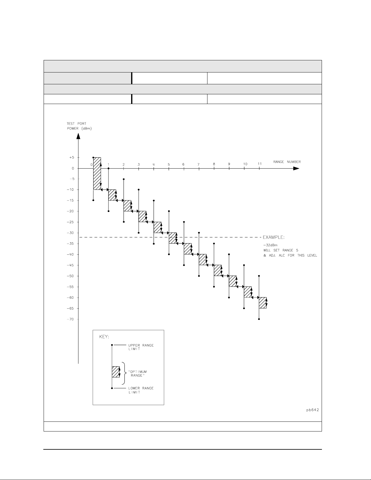
Table 1-25 Test Port Output
8719ES/20ES Test Port Output
Description Specification Supplemental Information
Output Power
Power Resolution 0.01 dB
Attenuato r Swi tch Points:
Note: For Option 400, the switch point betw een Range 0 and Rang e 1 is 0 dBm.
1-28

8719/20/22ES Specifications and Characteristics
Instrument Specifications
Table 1-26 Test Port Output
8722ES Test Port Output
Descriptio n Specification Supplemental Information
Output Power
Power Resolution 0.01 dB
Attenuator Switch Points:
Note: For Option 400, the switch point between Range 0 and Rang e 1 is −10 dBm.
1-29

8719/20/22ES Specifications and Character istics
Instrument Specifications
Table 1-27 Test Port Output
8719ES/20ES Test Port Output
Description Specification Supplemental Information
Linearity
a
−5 dB from reference ±0.35 dB
+5 d B from r efer ence ±0.35 dB
−10 dB from referenc e ±0.6 dB
+10 dB from reference ±1.0 dB
Impedance
Standard 50 Ω, nomin a l
Attenuator Accuracy
b
0 dB reference; at 50 MHz
5 dB ±0.6 dB, char.
10 dB ±0.9 dB, char.
15 dB ±1.25 dB, char.
20 dB ±1.5dB, char.
25 dB ±2.0 dB, char.
30 dB ±2.5 dB, char.
35 dB ±2.8 dB, char.
40 dB ±3.0 dB, char.
45 dB ±3.1 dB, char.
50 dB ±3.2 dB, char.
55 dB ±3.2 dB, char.
Test Reference Powers:
Standard 8719/20ES: −5 dBm
8719/20ES Option 007: 0 dBm
a. Chan ge in so ur ce o utput power for a given change in source p owe r se tting at any given
frequency.
b. The accura cy, relative to the 0 dB setting, of each setting of an attenuator, at a given
frequency.
1-30

8719/20/22ES Specifications and Characteristics
Instrument Specifications
Table 1-28 Test Port Output
8722ES Test Port Output
Descriptio n Specification Supplemental Information
Linearity
a
−5 dB from reference
50 MHz to 20 GHz ±0.35 dB
20 GHz to 40 GHz ±0.6 dB
+5 dB from reference
50 MHz to 20 GHz ±0.35 dB
−10 dB from reference ±0.6 dB
Impedance
Standard 50 Ω, nominal
Attenuator Accura cy
b
0 dB reference; at 50 MHz
5 dB ±0 .5 dB, char.
10 dB ±0.5 dB, char.
15 dB ±0.6 dB, char.
20 dB ±0.6 dB, char.
25 dB ±0.7 dB, char.
30 dB ±0.7 dB, char.
35 dB ±1.0 dB, char.
40 dB ±1.0 dB, char.
45 dB ±1.2 dB, char.
50 dB ±1.2 dB, char.
55 dB ±1.6 dB, char.
Test Reference Powers:
Standard 8722ES: −10 dBm
8722ES Option 007: −5 dBm
a. Change in source output power for a given change in source power setting at any given
frequency.
b. The ac cur ac y, relative to the 0 dB setting, of each setting of an attenu ato r, at a give n
frequency.
1-31

8719/20/22ES Specifications and Character istics
Instrument Specifications
Table 1-29 Test Port Output
8719ES/20ES/22ES Test Port Output
Description Specification Supplemental Information
Signal Purity
2nd Harmonic 0.05 GHz to one half the maximum
source frequency
at the maximum output level < −15 dBc, typ.
Non-harmonic Spurious
Mixer Related
at 100 kHz offset < −40 dBc, typ.
at 200 kHz offset < −45 dBc, typ.
at > 200 kHz offset < −65 dBc, typ.
Phase Noise
60 kHz from carrier
at 2 GHz
60 kHz from carrier
at 20 GHz
< −55 dBc, typ.
< −35 dBc, typ.
1-32

8719/20/22ES Specifications and Characteristics
Instrument Specifications
Test Port Input
Table 1-30 Test Port Input
8719ES/20ES/22ES Test Port Input
Description Specification Supplemental Information
Frequency Range
8719ES 0 .05 to 13.51 GH z
8720ES 0 .05 to 20.05 GH z
8722ES 0 .05 to 40.05 GH z
Frequency Response (A, B, R)
Channel R
0.05 to 20.05 GHz ±1.5 dB, char.
20.05 to 32 GHz ±2.5 dB, char.
32 to 40 GHz +2.5 dB to −6 dB, char .
Channels A and B
50 to 500 MHz +2.5 dB to −28 dB, char.
0.5 to 20 GHz ±2.5 dB, char.
20 to 32 GHz ±3 dB, char.
32 to 40 GHz +3 dB to −6 dB, char.
Impedance
Standard 50 Ω, nominal .
Return Loss
Standa rd See uncorrected load match
chart.
Maximum Input Level
Standard +10 dBm
Compression See dynam ic accuracy chart.
Damage Level
Standard +30 dBm or > 40 Vdc, typ.
Option 012
test port +30 dBm or > 40 Vdc, typ.
direct sa m p l e r access +26 dBm o r > 0 Vdc, typ.
a
a. Maximum level at which no test port overload messages ar e seen.
1-33

8719/20/22ES Specifications and Character istics
Instrument Specifications
Table 1-31 Test Port Input
8719ES/20ES/22ES Test Port Input
Description Specification Supplemental Information
0.1 dB Compression (Option 012), direct receiver input
0.05 to 0.5 GHz −5 dBm, typ.
0.5 to 2 GHz −5 dBm, typ.
2 to 8 GHz −5 dBm, typ.
8 to 20 GHz −5 dBm, typ.
20 to 40 GHz −5 dBm, typ.
Average Noise Floor (Option 012) - 10 Hz IF BWa, direct receiver input
0.05 to 0.5 GHz −12 0 dBm, typ.
0.5 to 2 GHz −120 dBm, typ.
2 to 8 GHz −120 dBm, typ.
8 to 20 GHz −118 dBm, typ.
20 to 40 GHz −113 dBm, typ.
Frequency Offset Operation (Option 089)
Frequency Range 50 MHz to maximum frequency
Reference (R) Input Level
Maximum
8719ES/20ES −7 dBm, typ.
8722ES −12 dBm, typ.
Minimum
8719ES/20ES/22ES −34 dBm, typ.
LO Spectral Puri ty and
Accuracy
Maximum Spurious Input < −25 dBc, typ.
Residual FM < 20 kHz, typ.
Frequency Accu ra c y ±16 MHz, typ.
b
a. The receiver noise floor is specified as the mean of the linear magnitude noise floor trace
over the speci fied frequency band.
b. The RF source characteristics in this mode are dependent on the stability of the ex ternal
LO source. The RF source tracks the LO to mai ntain a stable IF signal at the R channel
receiv e r in p u t .
1-34

8719/20/22ES Specifications and Characteristics
Instrument Specifications
Table 1-32 Test Port Input
8719/20/22ES Test Port Input
Description Supplemen tal Information
System Bandwidths
3000 Hz 10 Hz
Trace Noise
Magnitude
0.05 GHz to 13.5 GHz < 0.03 dB rms, typ. < 0.003 dB rms, typ.
13.5 GHz to 20 GHz < 0.04 dB rms, typ. < 0.004 dB rms, typ.
20 GHz to 40 GHz < 0.15 dB rms, typ. < 0.015 dB rms, typ.
Phase
0.05 GHz to 13.5 GHz < 0.3° rms, typ. < 0.03° rms, typ .
13.5 GHz to 20 GHz < 0.4° rms, typ. < 0.04° rms, typ.
20 GHz to 40 GHz < 1.5° rms, typ. < 0.15° rms, typ.
a
a. Trace noise is defined for a transmission measurement in CW mode, using a
“through” cable having 0 dB loss, with the sou rce set to the lesser of the
maximum source output or to the maximum receiver input, and no
averaging. Trace noise is defined as the variation of a high level trace due to
noise.
Table 1-33 Test Port Input
8719/20/22ES Test Port Input
Description Specification Supplemental
Information
Reference Level
Magnitude
Range ±500 dB
Resolution 0.001 dB
Phase
Range ±500°
Resolution 0.01°
1-35

8719/20/22ES Specifications and Character istics
Instrument Specifications
Table 1-34 Test Port Input
8719/20ES Test Port Input
Dynamic Accuracy (Characteristic)
For input por ts 1 an d 2, accuracy of the t e st p o rt input pow e r re ad i ng relativ e to the re f e re nce
input power level.
• Inputs: testport 1 and 2
• For test port powers > −50 dBm and < 0 dBm, magn itude dynamic accuracy is
0.02 dB + 0.0015 dB/dB from the reference power, p has e dynamic accuracy is
0.132 deg + 0.0066 deg/dB from the reference power. For test port powers > −80 dBm and
< −50 dB m, m agn itude dyna m ic range is .02 dB + .003 dB/ dB from the referen ce pow er.
• For test port powers up to maximum source power.
1-36

Table 1-34 Test Port Input
8719/20ES Test Port Input
8719/20/22ES Specifications and Characteristics
Instrument Specifications
1-37

8719/20/22ES Specifications and Character istics
Instrument Specifications
Table 1-35 Test Port Input
8722ES Test Port Input
Dynamic Accuracy (Characteristic)
For input por ts 1 an d 2, accuracy of the t e st p o rt input pow e r re ad i ng relativ e to the re f e re nce
input power level.
• Inputs: testport 1 and 2
• For test port powers > −50 dBm and < 0 dBm, magn itude dynamic accuracy is
0.020 dB + 0.0015 dB/dB from the reference power, phase dynamic accuracy is
0.132 deg + 0.0066 deg/dB from the reference power. For test port powers > −80 dBm and
> −50 dB m, m agn itude dyna m ic range is .02 dB + .003 dB/ dB from the referen ce pow er.
• For test port powers up to 0 dBm.
1-38

Table 1-35 Test Port Input
8722ES Test Port Input
8719/20/22ES Specifications and Characteristics
Instrument Specifications
1-39

8719/20/22ES Specifications and Character istics
Instrument Specifications
General Information
Table 1-36 General Information
8719/20/22ES General Infor matio n
Descripti o n Specification Supplemental Information
Display Range
Magnitude ±200 dB (at 20 dB/div), max
Phase ±180°, max
Polar 10 pico units, min
1000 units, max
Display Resolution
Magnitude 0.001 dB/div, min
Phase 0.01°/div, min
Reference Value Range
Magnitude ±500 dB, max
Phase ±360 °, max
Reference Level Resolution
Magnitude 0.001 dB, min
Phase
Marker Resolution
Magnitude 0.001 dB, min
Phase
Polar 0.01 mUnit, min; 0.01, min
0.01
0.01
°, min
°, min
1-40

8719/20/22ES Specifications and Characteristics
Instrument Specifications
Table 1-37 General Information
8719/20/22ES General Informatio n
Description Spec ification Supplemental Informa tion
Group Delay
Aperture (selecta ble) (frequency span)/(n umber of
Maximum Aperture 20% of frequency span with smoothing ena bled
Range 1/2 × (1/minimum aperture)
Maximum Delay Limited to measuring no more
Accuracy See graph. C ha r.
The following graph shows gr o up delay accurac y with 3.5-mm full 2-port calibration and a 10 Hz
IF bandwidth. Inse rtion loss is assumed to be < 2 dB and electrical lengt h to be ten me ters.
a
points −1)
than 180° of phase change
within the minimum
aperture.)
In general, the following formula can be used to determine the accura cy, in se conds, of specific
group delay measurement:
b
±Relative Phase Accuracy
(deg)/[360 × Aperture (Hz)]
Depending on the aperture and device length, the phase accuracy used is either phase dynamic
accuracy specific atio n or wo r st cas e transmission uncertain ty p has e spec ificat io n.
a. Gro up de lay is comp uted by me asur ing the ph ase chan ge within a specified frequency
step (determined by the frequency span and the number of points per sweep .
b. Relative phase accuracy is an unspecified parameter . For very narrow apertures with
short devices under test, RF systematic error terms can be assumed constant. As
aperture and/or device elec trical length increase RF systematic errors become
increasingly important, eventually relative phase accuracy is the same as absolute phase
accuracy.
1-41

8719/20/22ES Specifications and Character istics
Instrument Specifications
Table 1-38 General Information
8719/20/22ES General Infor matio n
Description Supplemental Information
System Bandwidths
IF bandwidth sett ings 6000 Hz, nom.
3700 Hz, nom.
3000 Hz, nom.
1000 Hz nom.
300 Hz, nom.
100 Hz, nom.
30 Hz, nom.
10 Hz, nom.
Rear Panel
External Aux iliar y Input
Connector F ema l e BNC
Range ±10 V, typ.
External Trig ger Triggers on a positive or negative TTL transition or conta ct
closure to gr ound.
Damag e Le ve l < −0.2 V; > +5.2 V, typ.
Limi t Test Ou tp ut Fe m ale BNC.
Damag e Le ve l < −0.2 V; > +5.2 V, typ.
Test Sequence Output Outputs a TTL signal which can b e set to a TTL high pulse
(default) or low pulse at end of sweep; or a fixed TTL high or
low. If limit tes t is on, the end of sweep pulse occurs after the
limit test is valid. This is useful when used in conjunction with
test se quencing.
Test Set Inter connect 25-pin-D-sub (DB-25) female; use for external special test sets
(K36, K39, etc.)
Measure Restart Floating closure to restart measurement.
External AM Input ±1 volt in to a 5 kΩ resistor, 1 kHz maximum, resulti n g in
approximately 2 dB/volt amplitude modulation.
High Stability Frequency
Reference Output (10 MHz)
(Option 1D5)
Frequency 10.0000 MHz, char.
Frequency St ability
(0 °C to 55 °C)
Daily aging rate (after 30 days)
Year ly agin g rat e ±0.5 ppm/year, char.
Ouput ≥0 dBm, char.
Output Impedance 50 Ω, nom.
±0.05 ppm, char.
9
< 3 x 10
−
/day, char.
1-42

8719/20/22ES Specifications and Characteristics
Instrument Specifications
Table 1-39 General Information
8719/20/22ES General Informatio n
Description Speci fication Supplemental Information
Rear Panel
Te st Port B ias Input
Maximum voltage ±40 Vdc
Maximum curren t ±500 mA
External Reference In
Input Frequency 1, 2, 5, and 10 MHz ±200 Hz at 10 MHz
Input Power −1 0 dBm to +20 dBm, typ.
Input Impedance 50 Ω, nom.
VGA Video Output 15-pin mini D-Sub; female. Drives
VGA compatible monitors.
GPIB Type-57, 24-pin; Microribbon
female
Parallel Port 25-pin D-Sub (DB- 25); fem ale ;
may be used as printer port or
general purpose I.O . por t
RS232 9-pin D-Sub (DB-9); male
Mini-DIN Keyboard/Barcod e Reader 6-pin mini DIN (PS/2); female
Line Power A third-wire gr ou nd is requ ire d.
Frequency 47 Hz to 66 Hz
Volt age at 115 V setting 90 V to 132 V 115 V, nom .
Voltage at 220 V setting 198 V to 265 V 230 V, nom.
VA Maximum 350 VA max
Front Pane l
RF Connectors
8719/20 3.5 -mm prec isio n
8722 2.4-mm precision
1-43

8719/20/22ES Specifications and Character istics
Instrument Specifications
Table 1-40 General Information
8719/20/22ES General Infor matio n
Description Specif ication
Front Panel
Display Pixel I ntegrity
Red, Green, or Blue Pixels Red, green, or blue “stu ck on” pixel s may
appear against a black background. In a
properly wor kin g disp lay, the following will
not occur:
• complete rows or c olumns of stuck pixels
• more than 5 stuck pixels (not to exceed a
maximum of 2 red or blue, and 3 green)
• 2 or more co nsecutive stuc k p i xe ls
• stuck pixels less than 6.5 mm apart
Dark Pixels Dark “stuck on” pixels may appear against a
white background. In a properly workin g
display, the f ol low ing will no t o ccur :
• more than 12 stuck pixels (not to exceed a
maximum of 7 red, green, or blue)
• more than one occurrence of 2
consecutive stuck pixels
• stuck pixels less than 6.5 mm apart
1-44

8719/20/22ES Specifications and Characteristics
Instrument Specifications
Table 1-41 General Information
8719/20/22ES General Informatio n
Descriptio n Specificatio n Supplemental Information
Gener a l Environmenta l
RFI/EMI Susc ept ibility Defined by CISPR Pub. 11 and
FCC Class B standards.
ESD Minimize usin g stat ic-safe
work procedures and an
antistatic bench mat
(part number 9300-0797).
Dust Minimize for optimum
reliability.
Operating Environment
Temperature 0 °C to +55 °C Instrument powers up, phase
locks, and displays no error
messages within this
temperat ure range.
Error-corrected temperature
range
Humidity 5% to 95% at +40 °C
(non-condensing)
Altitude 0 to 4.5 km (15,000 ft)
Storage Conditions
Temperature −40 ×°C to +70 °C
Humidity 0% to 95% RH at +65 °C
(non-condensing)
Altitude 0 to 15.24 km (50,000 ft)
Cabinet Dimensions
Height x Width x Depth 222 x 425 x 457 mm, nom.
Weight
Shipping 41 kg (90 lb), nom.
Net 27 kg (60 lb), nom.
Internal Memory - Data Retention Time with 3 V, 1.2 Ah Battery
70 °C 250 days (0.68 year), typ.
40 °C 1244 days (3.4 years), typ.
25 °C 10 years, typ.
see system specifications
(8.75 x 16.75 x 18 in, nom.)
Cabi ne t dime nsions exclude
front and rear protrusions .
a
a. Analyzer power is switched off.
1-45

8719/20/22ES Specifications and Character istics
Instrument Specifications
Speed Parameters
Table 1-42 8719/20/22ES Measurement and Data Transfer Speed Performance
Typical Time for Completion (ms)
Number of Points
Description
51 201 401 1601
Swept Stepped Swept Stepped Swept Stepped Sw ept Stepped
Typical Time for Completion (in ms), Center 1 GHz, Span 10 MHz, IFBW=6000
Uncorrected 27 134 65 492 116 970 419 3836
a
1-port and Enh. Resp. cal
2-port cal
b
27 134 65 492 116 970 419 3836
80 492 158 1034 259 2010 866 7885
Typical Time for Completion (in ms), Start 50 MHz, Stop 13.5 GHz, IFBW=6000
Uncorrected 484 597 553 1014 614 1490 926 4336
a
1-port and Enh. Resp. cal
2-port cal
b
484 597 553 1014 614 1490 926 4336
996 1222 1133 2069 1259 305 7 1876 8892
Typical Time for Completion (in ms), Start 50 MHz, Stop 20 GHz, IFBW=6000
Uncorrected 449 581 538 1017 598 1490 900 4335
a
1-port and Enh. Resp. cal
2-port cal
b
449 581 538 1017 598 1490 900 4335
930 1192 1106 2172 1227 305 3 1826 8892
Typical Time for Completion (in ms), Start 50 MHz, Stop 40 GHz, IFBW=6000
Uncorrected 570 731 651 1162 707 1690 961 4519
a
1-port and Enh. Resp. cal
2-port cal
Time Domain
b
c
(increase over uncorrected sweep time), Gating in Frequency Domain
570 731 651 1162 707 1690 961 4519
1168 1162 1333 2367 1444 3439 1949 9269
Transform 134287380
Gating 15 41 81 350
GPIB Da ta Transfe r
d
:
Binary (Internal) 11 15 20 54
IEEE floating point format
32 bit 11 18 26 78
64 bit 13 24 40 134
ASCII 33 105 203 781
a. S11 1-port calibration, with a 6 kHz IF bandwidth. Includes system retrace time, but does
not include bandswitch time. Time domain gating is assume d off.
b. S21 measu rem ent wi th full 2-po rt calibra tio n, usin g a 6 kHz IF bandwidt h. Includes
system retrace tim e and RF swit chin g tim e, but does not include bandswitch time. Time
domain gating is assumed off.
c. Option 010 only, gating off.
d. Measured with HP Omnibook 7100 Pentium Pro computer.
1-46

8719/20/22ES Specifications and Characteristics
Instrument Specifications
Table 1-43 8719/20/22ES Recall and Sweep Speed Performance
Total Time,
Typical (secs)
Raw
Operations Channel Points
Error Correction
ON
Recall and Sweep Single Chan. 201 On 0.654 0.546 0.497 0.394
Recall and Sweep Single Chan. 201 Off 0.605 0.496 0.448 0.344
Sweep only (no Recall) Single Chan. 201 N/A 0.158 0.152 N/A N/A
Recall and Sweep Single Chan. 1601 On 1.738 1.602 0.873 0.741
Recall and Sweep Single Chan. 1601 Off 1.358 1.225 0.492 0.363
Sweep only (no Recall) Single Chan. 1601 N/A 0.866 0.861 N/A N/A
Recall and Sweep Dual Chan. 201 On 0.803 0.640 0.604 0.448
Recall and Sweep Dual Chan. 201 Off 0.754 0.591 0.555 0.399
Sweep only (no Recall) Dual Cha n. 201 N/A 0.199 0.193 N/ A N/A
Recall and Sweep Dual Chan. 1601 On 2.630 2.460 1.438 1.277
Recall and Sweep Dual Chan. 1601 Off 2.252 2.083 1.060 0.899
Sweep only (no Recall) Dual Cha n. 1601 N/A 1.192 1.184 N/ A N/A
Error Correction
OFF
Recall and Sweep Single Chan. 201 On 0.523 0.421 0.458 0.360
Recall and Sweep Single Chan. 201 Off 0.511 0.409 0.445 0.348
Sweep only (no Recall) Single Chan. 201 N/A 0.065 0 .06 1 N/A N/A
Recall and Sweep Single Chan. 1601 On 0.955 0.860 0.537 0.446
Recall and Sweep Single Chan. 1601 Off 0.862 0.767 0.443 0.352
Sweep only (no Recall) Single Chan. 1601 N/A 0.419 0 .41 5 N/A N/A
Recall and Sweep Dual Chan. 201 On 0.568 0.445 0.502 0.384
Recall and Sweep Dual Chan. 201 Off 0.543 0.420 0.477 0.359
Sweep only (no Recall) Dual Chan. 201 N/A 0.066 0.061 N/A N/A
Recall and Sweep Dual Chan. 1601 On 1.082 0.970 0.662 0.555
Recall and Sweep Dual Chan. 1601 Off 0.891 0.778 0.471 0.364
Sweep only (no Recall) Dual Chan. 1601 N/A 0.420 0.414 N/A N/A
Instrument State: CF = 1 GHz, Span = 2 MHz, IF BW = 6 kHz. GPIB commands sent for timing are
Recall;OPC?;SING; or, for sweep only, OPC?;SING;.
Offset
Blank
Off
Blank
On
Recall-Only
Time, Typical
(secs)
Blank
Off
Blank
On
1-47

8719/20/22ES Specifications and Character istics
Instrument Specifications
Table 1-44 Sweep Time vs. IF Bandwidth
IF Bandwidt h
Typical Sweep Time (seconds)
6000 0.066
3700 0.091
3000 0.116
1000 0.243
300 0.700
100 2.018
30 7.058
10 21.475
a. Preset condition, CF = 1 GHz, Span = 100 MHz; includes retrace time, 201 points.
Table 1-45 Sweep Time vs. Number of Points
Number of Points
51 0.034
101 0.053
201 0.091
401 0.167
801 0.318
1601 0.621
Typical Sweep Time (secon ds) a
a
a. Preset condition, CF = 1 GHz, S pan = 100 MHz, Correction off; includes retrace time,
3700 points. Measurement speed can be im prove d by se lecti ng th e wi des t IF
bandwidth setting of 6000 Hz.
1-48

8719/20/22ES Specifications and Characteristics
Instrument Specifications
Power Meter Calibration Accuracy
Table 1-46 Power Meter Calibration Sweep Speed and Accuracy
Power De sired at
Tes t P ort
+5 dBm
−15 dBm
−30 dBm
a. Sweep speed applies to every sweep in continuous correction mode, and to the first
sweep in sample-and-sweep mode. Subsequent sweeps in sample-and-sweep mode
will be much faster .
b. The accuracy values were derived by combining the accuracy of the power meter and
linearity of the analyz er’ s inter nal so ur ce, as well as the m ism at ch un cert ainty
associated with the power sensor.
Number of
Readings
1
2
3
1
2
3
1
2
3
Sweep Time
Setting (s econds)
33
64
95
48
92
123
194
360
447
Characteristic
a
Accuracy (dB)
±0.7
±0.2
±0.1
±0.7
±0.2
±0.1
±0.7
±0.2
±0.1
b
1-49

8719/20/22ES Specifications and Character istics
Instrument Specifications
1-50

2 8719/20/22ET
Specifications and Characteristics
2-1

8719/20/22ET Specifications and Characteristics
Definitions
Definitions
All specifications and characteristics apply over a 23 °C ±3 °C range (unless otherwise
stated) and 1/2 hour after the instrument has been turned on.
Specification (spec.): Warranted performance. Specifications include gua rdbands to
account for the expected statistical performance distribution, measurement uncertainties,
and changes in performance due to environmental conditions.
Characte ristic (char.): A performance parameter that the prod uct is expected to meet
before it leaves the factory, but that is not verified in the field and is not covered by the
product warranty. A characteristic includes the sa m e guardbands as a specification.
Typical (typ.): Expected performance of an average unit which does not include
guardbands. It is not covered by the product wa rranty.
Nominal (nom.): A general, descriptive term that d oes not imply a level of performance. It
is not covered by the product warranty.
Calibration : The process of measuring know n standards from a calibration kit to
characterize a netw ork analyzer’s systematic (repeatable) errors.
Corrected (residual) Performance: Indicates performance after error correction
(calibration). It is determined by the quality of ca libration standards and how well
“known” they are, plus system repeatability, stability, and noise.
Uncorrec ted (raw) Performance: Indicates instrument performance without error
correction. The unc orrected performance affects the stability of a calib ration.
Standard: When referring to the analyzer, this includes all options unless noted otherwise.
2-2

8719/20/22ET Specifications and Characteristics
Corrected System Performance (8719/20ET)
Corrected System Performance (8719/20ET)
The specifications in this sec tion apply for meas urements made using 10 Hz IF bandwidth,
no averaging, and at an environmental temperature of 23 ±3 °C, with less than 1 °C
deviation from the calibration temperature. Assumes that an isolation calibration was
performed with an averaging factor of 8.
Table 2-1 System Dynamic Range, All Device Connector Types
8719/20ET, All Options, All Cal Kits, All Cables, 10 Hz IF BW
Description Specification Supplemental
Information
System Transmissio n Dynamic Range
50 MHz to 840 MHz 102 dB
840 MHz to 8 GHz 104 dB
8 GHz to 20 GHz 104 dB
a
a. The System Transmission Dynamic Range is calculated as the difference
between the receiver noise floor and the lesser of either: the source maximum
output or the receiver maximum input. Th e rece iver noise floor is speci f i ed as
3 standard deviation s above the mean of t he linear mag nitude noise fl oor t race
over the specified frequency band.
Table 2-2 System Dynamic Range, All Device Connector Types
8722ET, All Options, All Cal Kits, All Cables, 10 Hz IF BW
Description Specification Supplemental
Information
System Transmissio n Dynamic Range
50 MHz to 840 MHz 98 dB
840 MHz to 8 GHz 102 dB
8 GHz to 20 GHz 100 dB
20 GHz to 40 GHz 89 dB
a. The System Transmission Dynamic Range is calculated as the difference
between the receiver noise floor and the lesser of either: the source maximum
output or the receiver maximum input. Th e rece iver noise floor is speci f i ed as
3 standard deviation s above the mean of t he linear mag nitude noise fl oor t race
over the specified frequency band.
a
2-3

8719/20/22ET Specifications and Characteristics
Corrected System Performance (8719/20ET)
Table 2-3 3.5-mm (50 Ω) Device Connector Type
Network Analyzer: 8719/20ET Standard or Option 004 Attenuator
Calibration Kit: 85052B (3.5-mm, 50 Ω) Cal Kit
Cables: 85131E
Calibration: One-Port, Response, or Enhanced Response
IF BW = 10 Hz, Avg = off, T emp = 23 ± 3°C with < 1°C deviation from cal tem p, Isol cal with avg = 8
Specifica tion
Description
Reflection Measurements
Directivity (dB) 48 48 44 44
Source Match (dB) 40 40 33 31
Load Match (dB)
One-Port Cal 22 22 22 17
Tracking
Magnitude (dB) ±( 0.006 + .02/° C) ±(0.006 + .03/° C) ±(0.006 + .03/° C) ±(0.008 + .04/° C)
Phase (deg) ±(0.040 + .1/°C) ±(0.040 + .1/°C) ±(0.040 + .3/°C) ±(0.053 + 0.5/°C)
Transmission Measurements
Source Ma tch (dB)
Enhanced
Response Cal
Response Only Cal 16 20 14 11
Load Match (dB) 22 22 22 17
Tracking
Enhanced
Response Cal
Magnitude (dB) ±(0.014 + .02/° C) ±(0.012 + .03/° C) ±(0.027 + .03/° C) ±(0.050 + .04/° C)
Phase (deg ) ±(0.092 + .1/°C) ±(0.079 + .1/°C) ±(0.178 + .3/°C) ±(0.33 + 0.5/°C)
Response Only Cal
Magnitude (dB) ±(0.109 + .02/° C) ±(0.069 + .03/° C) ±(0.137 + .03/° C) ±(0.339 + .04/° C)
Phase (deg ) ±(0.719 + .1/°C) ±(0.455 + .1/°C) ±(0.904 + .3/°C) ±(2.237 + 0.5/°C)
Uncertainty graphs are on the following page.
50 to 500 MHz 0.5 to 2 GHz 2 to 8 GHz 8 to 20 GHz
a
b
40 40 33 31
a. One-port or enhanced response calibra tion.
b. Enhanced response or response only calibrat ion.
2-4

8719/20/22ET Specifications and Characteristics
Corrected System Performance (8719/20ET)
Transmissiona Uncertainty: Enhanced Response Calibration (Specification)
Transmission Uncer t ainty: Response Calibration (Specification)
Reflection Uncertainty: One-Port Calibration (Specification)
a. O ptio n 004 ma y deg rade tran sm ission source match as much as 2 dB, resulting in up to
0.05 dB additional uncer tainty in transmission uncer tain ty.
2-5

8719/20/22ET Specifications and Characteristics
Corrected System Performance (8719/20ET)
This page is intent ionally left blan k.
2-6

8719/20/22ET Specifications and Characteristics
Corrected System Performance (8722ET)
Corrected System Performance (8722ET)
The specifications in this sec tion apply for meas urements made using 10 Hz IF bandwidth,
no averaging, and at an environmental temperature of 23 ±3 °C, with less than 1 °C
deviation from the calibration temperature. Assumes that an isolation calibration was
performed with an averaging factor of 8.
2-7

8719/20/22ET Specifications and Characteristics
Corrected System Performance (8722ET)
Table 2-4 2.4-mm (50 Ω) Device Connector Type
Network Analyzer: 8722ET Standard or Option 004 Attenuator
Calibration Kit: 85056A (2.4-mm, 50 Ω)
Cables: 85133E
Calibration: One-Port, Response, or Enhanced Response
IF BW = 10 Hz, Avg = off, T emp = 23 ± 3°C with < 1°C deviation from cal tem p, Isol cal with avg = 8
Specification
Description
Reflection Measurements
Directivity (dB) 42 42 42 3 8
Source Match (dB) 41 38 38 33
Load Match (dB)
One-Port Cal 22 20 20 15
Tracking
Magnitude (dB) ±(0. 005 + .03/°C) ±(0.010 + .03/°C) ±(0.010 + .04/°C) ±(0.021 + .06/ °C)
Phase (deg) ±(0.033 + .1/°C) ±(0.066 + .3/°C) ±(0.066 + .5/°C) ±(0.139 + 1.0/°C)
Transmission Measurements
Source Ma tch (dB)
Enhanced
Response Cal
Response Only
Cal
Load Match (dB) 22 20 20 15
Tracking
Enhanced
Response Cal
Magnitude (dB) ±(0.018 + .03/°C) ±(0.026 + .03/ °C) ±(0.031 + .04/°C) ±(0.069 + .06/°C)
Phase (deg ) ±(0. 119 + .1/°C) ±(0.172 + .3/°C) ±(0. 205 + .5/°C) ±(0.455 + 1.0/°C)
Response Only
Cal
Magnitude (dB) ±(0.109 + .03/°C) ±(0.172 + .03/°C) ±(0.241 + .04/°C) ±(0.475 + .06/°C)
Phase (deg ) ±(0.719 + .0 1/°C) ±(1.135 + .3/°C) ±(1.59 + .5/°C) ±(3.135 + 1.0/°C)
Uncertainty graphs are on the following page.
0.05 to 2 GHz 2 to 8 GHz 8 to 20 GHz 20 to 40 GHz
a
b
41 38 38 33
16 14 11 10
a. One-port or enhanced response calibra tion.
b. Enhanced response or response only calibrat ion.
2-8

8719/20/22ET Specifications and Characteristics
Corrected System Performance (8722ET)
Transmissiona Uncertainty: Enhanced Response Calibration (Specification)
Transmission Uncer t ainty: Response Calibration (Specification)
Reflection Uncertainty: One-Port Calibration (Specification)
a. O ptio n 004 ma y deg rade tran sm ission source match as much as 2 dB, resulting in up to
0.05 dB additional uncer tainty in transmission uncer tain ty.
2-9

8719/20/22ET Specifications and Characteristics
Instrument Specifications
Instrument Specifications
Uncorrected Port Performance
Table 2-5 3.5-mm (50 Ω) Device Connector Type
8719/20ET (3.5-mm, 50 Ω)
Specification
Description
Directivity
Source Matc h
Load Match
a
(dB)
a
a
(dB)
(dB)
Reflection
Tracking
Transmission
b
(dB)
a
Tracking ( dB )
Tracking Stability
(Rat io Measu r ement)
Magnitude (dB) 0.02/°C, typ. 0.03/°C, typ. 0.03/°C, typ. 0.04/°C, typ.
Phase (deg) 0.1/°C, typ. 0.1/°C, typ. 0.3/°C, typ. 0.5/°C, typ.
Crosstalk
c
(dB)
50 to 500 MHz 0.5 to 2 GHz 2 to 8 GHz 8 to 20 GHz
24 27 21 16
16 20 14 11
22 22 22 17
± 3 ± 3 ± 3 ± 3
± 3 ± 3 ± 3 ± 3
101 101 101 93
a. Does not include effects of cable on test ports.
b. Does not incl ude rollo ff below 500 MH z whi ch is typic ally −18 dB at 100 MHz, and
−25 dB at 50 MHz.
c. Measurement conditions: Normalized to a thru, measured with two shorts, 10 Hz IF
bandwidth, av eraging factor of 8, al ternate mode, source power set to the lesser of the
maximum power out or the maximum receiver power.
2-10

8719/20/22ET Specifications and Characteristics
Instrument Specifications
Table 2-6 2.4-mm (50 Ω) Device Connector Type
8722ET (2.4-mm, 50 Ω)
Specification
Description
a
Directivity
(dB)
Source Match
50 to 500 MHz
a
23 23 21 16 15
16 20 14 11 10
(dB)
Load Match
a
22 20 20 20 15
(dB)
Reflection
b
± 3 ± 3 ± 3 ± 3 ± 4
Tracking (dB)
Transmission
a
± 3 ± 3 ± 3 ± 3 ± 3
Tracking (dB)
Tracking
Stability (Ratio
Measurement)
Magnitude
0.02/°C, typ. 0.03/°C, typ. 0.03/°C, typ. 0.04/°C, typ. 0.06/°C, typ.
(dB)
Phase (deg) 0.1/°C, typ. 0.1/°C, typ. 0.3/°C, typ. 0.5/°C, ty p. 1.0/°C, typ.
Crosstalk
c
(dB)
95 95 95 88 82
0.5 to 2 GHz 2 to 8 GHz 8 to 20 GHz 20 to 40 GHz
a. Does not include effects of cable on test ports.
b. Does not include rolloff below 500 MHz which is typically −18 dB at 100 MHz, and −25 dB at
50 MHz.
c. Measurement conditions: Normalized to a thru, measured with two shorts, 10 Hz IF
bandwidth, averaging factor of 8, alternate mode, source power set to the lesser of the
maximum power out or the maximum receiver power.
2-11

8719/20/22ET Specifications and Characteristics
Instrument Specifications
Test Port Output
Table 2-7 Test Port Output
8719ET/20ET/22ET Test Port Output
Description Specification Supplemental Information
Frequency
Range
8719ET 0.05 to 13.51 GHz
8720ET 0.05 to 20.05 GHz
8722ET 0.05 to 40.05 GHz
Resolution 1 Hz
Stability
Standard
Option 1D5
CW Accuracy ± 10 ppm at 23 °C± 3 °C
±7.5 ppm, 0° to 55 °C, t y p.
±3 ppm/year, typ.
±0.05 ppm, 0° to 55°C, typ.
±0.5 ppm/year, typ.
2-12

8719/20/22ET Specifications and Characteristics
Instrument Specifications
Table 2-8 Test Port Output
8719ET/20ET/22ET Test Port Output
Description Specification Supplemental Information
Output Power
Level Accuracy
8719ET/20ET ± 2 dB at 5 dBm
8722ET ± 3 dB at −5 dBm
Maximum Leveled Power
8719/20ET +10 dBm, char.
8722ET
0.05 to 20 GHz 0 dBm, char.
20 to 40 GHz −5 dBm, char.
Power Range
8719/20ET (Standard) −10 to +10 dBm −18 to +12 dBm, typ.
8719/20ET (Option 004) −65 to +10 dBm
8722ET (Standard)
0.05 to 20 GHz −15 to 0 dBm −23 to +2 dBm, typ.
20 to 40 GHz −15 to −5 dB m −23 to −3 dBm , typ.
8722ET (Option 004)
0.05 to 20 GHz −70 to 0 dBm
20 to 40 GHz −70 to−5 dBm
Power Sweep Range
8719/20ET 20 dB 30 dB, typ.
8722ET
0.05 to 20 GHz 15 dB 25 dB, typ.
20 to 40 GHz 10 dB 20 dB, typ.
a
b
c
a. Absolute power accuracy at a given power level. Includes absolute accuracy and relative
flatness across frequency.
b. At any given frequency, the achievable power while remaining leveled. Applies to CW
mode only.
c. Power to which the source can be set and phase lock is assured.
2-13

8719/20/22ET Specifications and Characteristics
Instrument Specifications
Table 2-9 Test Port Output
8719ES/20ET Test Port Output
Description Specification Supplemental Information
Output Power (Option 004 Only)
Power Resolution 0.01 dB
Attenuato r Swi tch Points:
2-14

8719/20/22ET Specifications and Characteristics
Instrument Specifications
Table 2-10 Test Port Output
8722ET Test Port Output
Descriptio n Specification Supplemental Information
Output Power (Option 004 Only)
Power Resolution 0.01 dB
Attenuator Switch Points:
2-15

8719/20/22ET Specifications and Characteristics
Instrument Specifications
Table 2-11 Test Port Output
8719ET/20ET Test Port Output
Description Specification Supplemental Information
Output Power
Linearity
a
−5 dB from reference ± 0.35 dB
+5 dB from reference ± 0.35 dB
−10 dB from reference
± 0.6 dB
+10 dB from reference ± 1.0 dB
Impedance
Standard 50 Ω, nominal
Attenuator Accuracyb (Option 004 Only)
0 dB reference; at 50 MHz
5 dB ±0.6 dB, char.
10 dB ±0.9 dB, char.
15 dB ±1.25 dB, char.
20 dB ±1.5 dB, char.
25 dB ±2.0 dB, char.
30 dB ±2.5 dB, char.
35 dB ±2.8 dB, char.
40 dB ±3.0 dB, char.
45 dB ±3.1 dB, char.
50 dB ±3.2 dB, char.
55 dB ±3.2 dB, char.
Tes t Re fe rence Po wer: 0 dBm
a. Chan ge in so ur ce ou tput power for a given chan ge in source power se ttin g at any
given frequency.
b. The accurac y, relativ e to the 0 dB setti ng, of each setting of an atten uator , at a
given frequency.
2-16

8719/20/22ET Specifications and Characteristics
Instrument Specifications
Table 2-12 Test Port Output
8722ET Test Port Output
Description Specification Supplemental Information
Output Power
Linearity
a
−5 dB from r eference
50 MHz to 20 GHz ± 0. 35 dB
20 GHz to 40 GHz ± 0.6 dB
+5 dB from reference
50 MHz to 20 GHz
−10 dB from reference
± 0.35 dB
± 0.6 dB
Impedance
Standard 50 Ω, nominal
Attenuator Accuracyb (Option 004 Only)
0 dB reference; at 50 MHz
5 dB ±0.5 dB, char.
10 dB ±0.5 dB, char.
15 dB ±0.6 dB, char.
20 dB ±0.6 dB, char.
25 dB ±0.7 dB, char.
30 dB ±0.7 dB, char.
35 dB ±1.0 dB, char.
40 dB ±1.0 dB, char.
45 dB ±1.2 dB, char.
50 dB ±1.2 dB, char.
55 dB ±1.6 dB, char.
Test Reference Powe r: −5 dBm
a. Change in source output power for a given change in source power setting at any
given frequ en cy .
b. The accuracy, relative to the 0 dB setting, of each setting of an attenuator, at a
given frequ en cy .
2-17

8719/20/22ET Specifications and Characteristics
Instrument Specifications
Test Port Input
Table 2-13 Test Port Input
8719ET/20ET/22ET Test Port Input
Description Specification Supplemental Information
Frequency Range
8719ET 0.05 to 13.51 GH z
8720ET 0.05 to 20.05 GH z
8722ET 0.05 to 40.05 GH z
Frequency Response (B, R)
Channel R
0.05 to 20.05 GHz ± 1.5 dB, char.
20.05 to 32 GHz ± 2.5 dB, char.
32 to 40 GHz +2.5 dB to −6 dB, char.
Channel B
0.05 to 20.05GHz ± 2.5 dB, char.
20 to 32 GHz ± 3.0 dB, char.
32 to 40 GHz +3.0 dB to −6 dB, char.
Impedance
Standard 50 Ω, nomin a l .
Return Loss
Standard See unco rrected load match chart.
Maximum Input Level
Standard +5 dBm, Transmission Po rt
Damage Level
Standard +27 dBm or > 0 Vdc, typ.
Compress ion See dynam ic accuracy chart.
a
+10 dBm, Reflection Port
a. Maxim um leve l at which no test port overload m essages are seen.
2-18

Table 2-14 Test Port Input
8719/20/22ET Test Port Input
8719/20/22ET Specifications and Characteristics
Instrument Specifications
Description
Suppl emental Info rmation
System Bandwidths
3000 Hz 10 Hz
Trace Noise
a
Magnitude
0.05 GHz to 13.5 GHz < 0.03 dB rms, typ. < 0.003 dB rms, typ.
13.5 GHz to 20 GHz < 0.04 dB rms, typ. < 0.004 dB rms, typ.
20 GHz to 40 GHz < 0.15 dB rms, typ. < 0.015 d B rms, typ.
Phase
0.05 GHz to 13.5 GHz < 0.3° rms, typ. < 0. 03° rms, typ.
13.5 GHz to 20 GHz < 0.4° rms, typ. < 0.04° rms, typ.
20 GHz to 40 GHz < 1.5° rms, typ. < 0.15° rms, typ.
a. Trace noise is defined for a transmission measurement in CW mode, using a
“through” cable havin g 0 dB loss, and a short for a reflection meas ur em ent,
with the sour ce se t to the lesse r o f the ma x im um so ur ce outp ut or the
maximum receiver input, and no averaging. Trace noise is defined as the
variation of a high lev e l trace due to noise.
Table 2-15 Test Port Input
8719/20/22ET Test Port Input
Description Specification Supplemental
Information
Reference Level
Magnitude
Range ± 500 dB
Resolution 0.001 dB
Phase
Range ± 500°
Resolution 0.01°
2-19

8719/20/22ET Specifications and Characteristics
Instrument Specifications
Table 2-16 Test Port Input
8719/20ET Test Port Input (Transmission)
Dynamic Accuracy (Characteristic)
For transmi ssio n accuracy o f th e te st port inp ut p o w e r re ad i ng relati ve to the reference inpu t
power level.
• Inputs: transmission port
• For test port powers up to 0 dBm.
2-20

Table 2-16 Test Port Input
8719/20ET Test Port Input (Transmission)
8719/20/22ET Specifications and Characteristics
Instrument Specifications
2-21

8719/20/22ET Specifications and Characteristics
Instrument Specifications
Table 2-17 Test Port Input
8719/20ET Test Port Input (Reflection)
Dynamic Accuracy (Characteristic)
For reflection accuracy of the test port input power reading relative to t he reference input power
level.
•Inputs: reflection port
• For test port powers up to 0 dBm.
2-22

Table 2-17 Test Port Input
8719/20ET Test Port Input (Reflection)
8719/20/22ET Specifications and Characteristics
Instrument Specifications
2-23

8719/20/22ET Specifications and Characteristics
Instrument Specifications
Table 2-18 Test Port Input
8722ET Test Port Input (Transmission)
Dynamic Accuracy (Characteristic)
For transmi ssio n accuracy o f th e te st port inp ut p o w e r re ad i ng relati ve to the reference inpu t
power level.
• Inputs: transmission port
• For test port powers up to 0 dBm.
2-24

Table 2-18 Test Port Input
8722ET Test Port Input (Transmission)
8719/20/22ET Specifications and Characteristics
Instrument Specifications
2-25

8719/20/22ET Specifications and Characteristics
Instrument Specifications
Table 2-19 Test Port Input
8722ET Test Port Input (Reflection)
Dynamic Accuracy (Characteristic)
For reflection accuracy of the test port input power reading relative to t he reference input power
level.
•Inputs: reflection port
• For test port powers up to 0 dBm.
2-26

Table 2-19 Test Port Input
8722ET Test Port Input (Reflection)
8719/20/22ET Specifications and Characteristics
Instrument Specifications
2-27

8719/20/22ET Specifications and Characteristics
Instrument Specifications
General Information
Table 2-20 General Information
8719/20/22ET General Information
Description Specification Supplemental Information
Display Range
Magnitude ± 200 dB (at 20 dB/div), max
Phase ± 180°, max
Polar 10 pico units, min
1000 units, max
Display Resolution
Magnitude 0.001 dB/div, min
Phase 0.1°/div, min
Reference Level Range
Magnitude ± 500 dB, max
Phase ± 360 °, max
Reference Level Resolution
Magnitude 0.001 dB, min
Phase 0.01°, min
Marker Resolution
Magnitude 0.001 dB, min
Phase 0.01°, min
Polar 0.01 mUnit, min; 0.01, min
2-28

8719/20/22ET Specifications and Characteristics
Instrument Specifications
Table 2-21 General Information
8719/20/22ET General Information
Description Spec ification Supplemental Informa tion
Group Delay
Aperture (selecta ble) (frequency span)/(n umber of
Maximum Aperture 20% of frequency span
Range 1/2 × (1/minimum aperture)
Maximum Delay Limited to measuring no more
Accuracy See graph. C ha r.
The following graph shows gr o up delay accurac y with 3.5-mm full 2-p ort ca libr atio n and a 10 Hz
IF bandwidth. Inse rtion loss is assumed to be < 2 dB and electrical lengt h to be ten me ters.
a
points − 1)
than 180° of phase change
within the minimum
aperture.)
In general, the following formula can be used to determine the accura cy, in se conds, of specific
group delay measurement:
b
±Relative Phase Accuracy
(deg)/[360 × Aperture (Hz)]
Depending on the aperture and device length, the phase accuracy used is either phase dynamic
accuracy specific atio n or wo r st cas e transmission uncertain ty p has e spec ificat io n.
a. Gro up de lay is comp uted by me asur ing the ph ase chan ge within a specified frequency
step (determined by the frequency span and the number of points per sweep).
b. Relative phase accuracy is an unspecified parameter . For very narrow apertures with
short devices under test RF systematic error terms can be assumed constant. As aperture
and/or device electrical length increase RF systematic error s become increasingly
important, eventu ally relative phase accuracy is the sam e as absolu te phase accura cy.
2-29

8719/20/22ET Specifications and Characteristics
Instrument Specifications
Table 2-22 General Information
8719/20/22ET General Information
Description Supplemental Information
System Bandwidths
IF bandwidth sett ings 6000 Hz, nom.
3700 Hz, nom.
3000 Hz, nom.
1000 Hz nom.
300 Hz, nom.
100 Hz, nom.
30 Hz, nom.
10 Hz, nom.
Rear Panel
External Aux iliar y Input
Connector F ema l e BNC
Range 10 V, typ.
External Trig ger Triggers on a positive or negative TTL transition or conta ct
closure to gr ound.
Damag e Le ve l < −0.2 V; > +5.2 V, typ.
Limi t Test Ou tp ut Fe m ale BNC.
Damag e Le ve l < −0.2 V; > +5.2 V, typ.
Test Sequence Output Outputs a TTL signal which can b e set to a TTL high pulse
(default) or low pulse at end of sweep; or a fixed TTL high or
low. If limit tes t is on, the end of sweep pulse occurs after the
limit test is valid. This is useful when used in conjunction with
test se quencing.
Test Set Inter connect 25-pin-D-sub (DB-25) female; use for external special test sets
(K36, K39, etc.)
Measure Restart Floating closure to restart measurement.
External AM Input ± 1 volt into a 5 kΩ resistor, 1 kHz maximum , resulting in
approximately 2 dB/volt amplitude modulation.
High Stability Frequency
Reference Output (10 MHz)
(Option 1D5)
Frequency 10.0000 MHz, char.
Frequency St ability
(0 °C to 55 °C)
Daily aging rate (after 30 days)
Year ly agin g rat e ±0.5 ppm/year, char.
Output ≥ 0 dBm, char.
Output Impedance 50 Ω, nom.
±0.05 ppm, char.
9
< 3 x 10
−
/day, char.
2-30

8719/20/22ET Specifications and Characteristics
Instrument Specifications
Table 2-23 General Information
8719/20/22ET General Information
Description Speci fication Supplemental Information
Rear Panel
External Reference In
Input Frequency 1, 2, 5, and 10 MHz ± 200 Hz at 10 MHz
Input Power −1 0 dBm to +20 dBm, typ.
Input Impedance 50 Ω, nom.
VGA Video Output 15-pin mini D-Sub; female. Drives
VGA compatible monitors.
GPIB Type-57, 24-pin; Microribbon
female
Parallel Port 25-pin D-Sub (DB- 25); fem ale ;
may be used as printer port or
general purpose I.O . por t
RS232 9-pin D-Sub (DB-9); male
Mini-DIN Keyboard/Barcod e Reader 6-pin mini DIN (PS/2); female
Line Power A third-wire gr ou nd is requ ire d.
Frequency 47 Hz to 66 Hz
Volt age at 115 V setting 90 V to 132 V 115 V, nom .
Voltage at 220 V setting 198 V to 265 VAC 230 V, nom.
VA Maximum 350 VA max
Front Pane l
RF Connectors
8719/20 3.5 -mm prec isio n
8722 2.4-mm precision
2-31

8719/20/22ET Specifications and Characteristics
Instrument Specifications
Table 2-24 General Information
8719/20/22ET General Information
Description Specification
Front Panel
Display Pixel I ntegrity
Red, Green, or Blue Pixels Red, green , or blue "stuck on" pixels may
appear against a black background. In a
properly wor kin g disp lay, the following will
not occur:
• complete rows or c olumns of stuck pixels
• more than 5 stuck pixels (not to exceed a
maximum of 2 red or blue, and 3 green)
• 2 or more co nsecutive stuc k p i xe ls
• stuck pixels less than 6.5 mm apart
Dark Pixels Dark "stuck on" pixels may appear against a
white background. In a properly workin g
display, the f ol low ing will no t o ccur :
• more than 12 stuck pixels (not to exceed a
maximum of 7 red, green, or blue)
• more than one occurrence of 2
consecutive stuck pixels
• stuck pixels less than 6.5 mm apart
2-32

8719/20/22ET Specifications and Characteristics
Instrument Specifications
Table 2-25 General Information
8719/20/22ET General Information
Descriptio n Specificatio n Supplemental Information
Gener a l Environmenta l
RFI/EMI Susc ept ibility Defined by CISPR Pub. 11 and
FCC Class B standards.
ETD Minimize using static-sa fe
work procedures and an
antistatic bench mat
(part number 9300-0797).
Dust Minimize for optimum
reliability.
Operating Environment
Temperature 0° C to +55° C Instrument powers up, phase
locks, and displays no error
messages within this
temperat ure range.
Error-corrected temperature
range
Humidity 5% to 95% at +40 °C
(non-condensing)
Altitude 0 to 4.5 km (15,000 ft)
Storage Conditions
Temperature −40 °C to +70 °C
Humidity 0% to 95% RH at +65 °C
(non-condensing)
Altitude 0 to 15.24 km (50,000 ft)
Cabinet Dimensions
Height x Width x Depth 222 x 425 x 457 mm, nom.
Weight
Shipping 41kg (90 lb), nom.
Net 27 kg (60 lb), nom.
Internal Memory - Data Retention Time with 3 V, 1.2 Ah Battery
70° C 250 days (0.68 year), char.
40° C 1244 days (3.4 years), char.
25° C 10 years, char.
see system specifications
(8.75 x 16.75 x 18 in, nom.)
Cabi ne t dime nsions exclude
front and rear protrusions .
a
a. Analyzer power is switched off.
2-33

8719/20/22ET Specifications and Characteristics
Instrument Specifications
Speed Parameters
Table 2-26 8719/20/22ET Measurement and Data Transfer Speed Performance
Typical Time for Completion (ms)
Number of Points
Description
51 201 401 1601
Swept Stepped Swept Stepped Swept Stepped Sw ept Stepped
Typical Time for Completion (in ms), Center 1 GHz, Span 10 MHz, IFBW=6000
Uncorrected 27 134 65 492 116 970 419 3836
a
1-port and Enh. Resp. cal
2-port cal
b
27 134 65 492 116 970 419 3836
80 492 158 1034 259 2010 866 7885
Typical Time for Completion (in ms), Start 50 MHz, Stop 13.5 GHz, IFBW=6000
Uncorrected 484 597 553 101 4 614 1490 92 6 4336
a
1-port and Enh. Resp. cal
2-port cal
b
484 597 553 101 4 614 1490 926 4336
996 1222 1133 2069 1259 305 7 1876 8892
Typical Time for Completion (in ms), Start 50 MHz, Stop 20 GHz, IFBW=6000
Uncorrected 449 581 538 101 7 598 1490 90 0 4335
a
1-port and Enh. Resp. cal
2-port cal
b
449 581 538 101 7 598 1490 900 4335
930 1192 1106 2172 1227 305 3 1826 8892
Typical Time for Completion (in ms), Start 50 MHz, Stop 40 GHz, IFBW=6000
Uncorrected 570 731 651 116 2 707 1690 96 1 4519
a
1-port and Enh. Resp. cal
2-port cal
Time Domain
b
c
(increase over uncorrected sweep time), Gating in Frequency Domain
570 731 651 116 2 707 1690 961 4519
1168 1162 1333 2367 1444 3439 1949 9269
Transform 134287380
Gating 15 41 81 350
GPIB Da ta Transfe r
d
:
Binary (Internal) 11 15 20 54
IEEE floating point format
32 bit 11 18 26 78
64 bit 13 24 40 134
ASCII 33 105 203 781
a. S11 1-port calibra tio n, with a 6 kHz IF bandw idth. Includes system retrace time, but does
not include bandswitch time. Time domain gating is assume d off.
b. S21 measu rem ent wi th full 2-po rt calibra tio n, usin g a 6 kHz IF bandwidt h. Includes
system retrace tim e and RF swit chin g tim e, but does not include bandswitch time. Time
domain gating is assumed off.
c. Option 010 only, gating off.
d. Measured with HP Omnibook 7100 Pentium computer.
2-34

8719/20/22ET Specifications and Characteristics
Instrument Specifications
Table 2-27 8719/20/22ET Recall a nd Sweep Speed Performanc e
Total Time,
Typical (secs)
Raw
Operations Channel Points
Error Correction
ON
Recall and Sweep Single Chan. 201 On 0.654 0.546 0.497 0.394
Recall and Sweep Single Chan. 201 Off 0.605 0.496 0.448 0.344
Sweep only (no Recall) Single Chan. 201 N/A 0.158 0.152 N/A N/A
Recall and Sweep Single Chan. 1601 On 1.738 1.602 0.873 0.741
Recall and Sweep Single Chan. 1601 Off 1.358 1.225 0.492 0.363
Sweep only (no Recall) Single Chan. 1601 N/A 0.866 0.861 N/A N/A
Recall and Sweep Dual Chan. 201 On 0.803 0.640 0.604 0.448
Recall and Sweep Dual Chan. 201 Off 0.754 0.591 0.555 0.399
Sweep only (no Recall) Dual Cha n. 201 N/A 0.199 0.193 N/ A N/A
Recall and Sweep Dual Chan. 1601 On 2.630 2.460 1.438 1.277
Recall and Sweep Dual Chan. 1601 Off 2.252 2.083 1.060 0.899
Sweep only (no Recall) Dual Cha n. 1601 N/A 1.192 1.184 N/ A N/A
Error Correction
OFF
Recall and Sweep Single Chan. 201 On 0.523 0.421 0.458 0.360
Recall and Sweep Single Chan. 201 Off 0.511 0.409 0.445 0.348
Sweep only (no Recall) Single Chan. 201 N /A 0.065 0.061 N/A N/A
Recall and Sweep Single Chan. 1601 On 0.955 0.860 0.537 0.446
Recall and Sweep Single Chan. 1601 Off 0.862 0.767 0.443 0.352
Sweep only (no Recall) Single Chan. 1601 N/A 0.419 0 .41 5 N/A N/A
Recall and Sweep Dual Chan. 201 On 0.568 0.445 0.502 0.384
Recall and Sweep Dual Chan. 201 Off 0.543 0.420 0.477 0.359
Sweep only (no Recall) Dual Chan. 201 N/A 0.066 0.061 N/A N/A
Recall and Sweep Dual Chan. 1601 On 1.082 0.970 0.662 0.555
Recall and Sweep Dual Chan. 1601 Off 0.891 0.778 0.471 0.364
Sweep only (no Recall) Dual Chan. 1601 N/A 0.420 0.414 N/A N/A
Instrument State: CF = 1 GHz, Span = 2 MHz, IF BW = 6 kHz. GPIB commands sent for timing are
Recall;OPC?;SING; or, for sweep only, OPC?;SING;.
Offset
Blank
Off
Blank
On
Recall-Only
Time, Typical
(secs)
Blank
Off
Blank
On
2-35

8719/20/22ET Specifications and Characteristics
Instrument Specifications
Table 2-28 Sweep Time vs. IF Bandwidth
IF Bandwidt h
Typical Sweep Time (seconds)
6000 0.066
3700 0.091
3000 0.116
1000 0.243
300 0.700
100 2.018
30 7.058
10 21.475
a. Preset condition, CF = 1 GHz, Span = 100 MHz; includes retrace time, 201 points.
Table 2-29 Sweep Time vs. Number of Points
Number of Points
51 0.034
101 0.053
201 0.091
401 0.167
801 0.318
1601 0.621
Typical Sweep Time (secon ds) a
a
a. Preset condition, CF = 1 GHz, S pan = 100 MHz, Correction off; includes retrace time,
3700 points. Measurement speed can be im prove d by se lecti ng th e wi des t IF
bandwidth setting of 6000 Hz.
2-36

8719/20/22ET Specifications and Characteristics
Instrument Specifications
Power Meter Calibration Accuracy
Table 2-30 Power Meter Calibration Sweep S peed and Accuracy
Power Desired at
Tes t P ort
+5 dBm 1
−15 dBm 1
−30 dBm 1
Number of
Readings
2
3
2
3
2
3
Sweep Time
Setting (seconds)
33
64
95
48
92
123
194
360
447
Characteristic
a
Accuracy (dB)
±0.7
±0.2
±0.1
±0.7
±0.2
±0.1
±0.7
±0.2
±0.1
a. Sweep speed applies to every sweep in continuous correction mode, and to the first
sweep in sample-and-sweep mode. Subsequent sweeps in sample-an d-sweep mode
will be much faster .
b. The accuracy values were derived by combining the accuracy of the power meter and
linearity of the analyz er’ s inter nal so ur ce, as well as the m ism atc h un cert ainty
associated with the power sensor.
b
2-37

8719/20/22ET Specifications and Characteristics
Instrument Specifications
2-38

3 Front/Rear Panel
3-1

Front/Rear Panel
Front Panel Features
Front Panel Features
CAUTION Do not mistake the line switch for the disk eject button. See the following
illustrations. If the line switch is mistak enly pushed, the instrument will be
turned off, losing all settings and data that have not been saved.
Figure 3-1 8719/20/22ES Front Panel
3-2

Figure 3-2 8719/20/22E T Front Panel
Front/Rear Panel
Front Panel Features
The location of the following front panel features and key function blocks is show n in
Figure 3-1 and Figure 3-2. These features are described in more de tail later in this cha pter,
and in Chap ter 5 , “Hardkey/Softkey Reference.”
1. LINE switch. This switch control s ac power to the analyzer. 1 is on, 0 is
off.
2. Display. This shows the measurement data traces, measurement
annotation, and softkey labels. The display is divided into specific
information areas, illustra t e d in Fi gu re 3-3.
3. Disk drive. This 3.5 inch floppy-disk drive allows you to store and recall
instrument states and measurement results for l ater analysis.
4. Disk eject button.
5. Softkeys. These keys provide access to menus that are shown on the
display.
6. STIMULUS function block. The keys in this block allow you to control
the analyzer source's frequency, power, and other stimulus functions.
7. RESPONSE function block. The keys in this block a llow you to control
the measurement and display functions of the active display channel.
8. ACTIVE CHANNEL keys. The analyzer has two independent primary
channels and two auxiliary channels. These keys allow you to select the
active channel. Any function you enter applies to the selected channel.
3-3

Front/Rear Panel
Front Panel Features
9. The ENTRY block. This block includes the knob, the step
keys, the number pad, and the backspace key. These allow you to enter
numerical data and control the markers.
You can use the numeric keypad to select digits, decimal points, and a
minus sign for numerical entries. You must also select a units terminator
to complete value inputs.
The backspace key has two independent functi ons : i t modifi es entr ies, and
it turns off the softkey menu so that marker information can be moved off
of the grids and into the softkey menu area. For more details, refer to the
“Making Measurements” chapter in the user’s guide.
10. INSTRUMENT STATE function block. These keys allow you to c ontrol
channel-independent system functions such as the following:
• copying, save/recall, and GPIB controller mode
• limit testing
• tuned receiver mode
• frequency offset mode (Option 089)
• test sequence function
• time domain transform (Option 010)
GPIB STATUS indica tors are also included in this block.
11. key. This key returns the ins trument to either a known factory
Preset
preset state, or a user preset state that can be defined. Refer to Chapter 8 ,
“Preset State and Memory Allocation” for a com plete listing of the
instrument preset condition.
12. (ES) R CHANNEL connectors. These connectors allow you to apply an input
signal to the analyzer's R channel, for frequency offset mode.
13. (ES) PORT 1 and PORT 2. These ports output a signal from the source and
receive input signals f rom a device under test. PORT 1 allows y ou to
measure S
and S11. PORT 2 allows you to m easure S21 and S22.
12
13. (ET) REFLECTION and TRANSMISSION ports. The REFLECTION port
outputs a signal from the source and allows you to make reflection
measurements. The TRANSMISSION port receives input signals from a
device under test and a llows you to make transmission measurements.
3-4
 Loading...