


User’s Guide Supplement
Firmware Revisions 7.60 and Above
for the
HP 8719D/20D/22D,
HP 8753E, and HP 8753E Option 011
HP Part Number: 08753-90445
Printed in USA
December 1999
Supersedes October 1998
© Copyright 1998, 1999 Hewlett-Packard Company

How to Use This Guide
SOFTKEY
This guide uses the following conventions:
Front Panel Key
This represents a key physically located on the
instrument.
This represents a “softkey”, a key whose label is
determined by the instrument firmware.
ii

Contents
Introduction . . . . . . . . . . . . . . . . . . . . . . . . . . . . . . . . . . . . . . . . . . . . . . . . . . . . . . . . . . . . . . . . . 1
Four-Parameter Display Overview . . . . . . . . . . . . . . . . . . . . . . . . . . . . . . . . . . . . . . . . . . . . . . . 2
Four-Parameter Display and Calibration . . . . . . . . . . . . . . . . . . . . . . . . . . . . . . . . . . . . . . . . 3
Enabling and Activating the Auxiliary Channels. . . . . . . . . . . . . . . . . . . . . . . . . . . . . . . . . . 3
Quick Four-Parameter Display Setup. . . . . . . . . . . . . . . . . . . . . . . . . . . . . . . . . . . . . . . . . . . . . 4
Measurement Examples . . . . . . . . . . . . . . . . . . . . . . . . . . . . . . . . . . . . . . . . . . . . . . . . . . . . . . . 5
Displaying All Four S-Parameters of a Two-Port Device . . . . . . . . . . . . . . . . . . . . . . . . . . . . 5
Activate the Auxiliary Channels . . . . . . . . . . . . . . . . . . . . . . . . . . . . . . . . . . . . . . . . . . . . . 8
Uncouple the Display Markers. . . . . . . . . . . . . . . . . . . . . . . . . . . . . . . . . . . . . . . . . . . . . . . 8
Characterizing a Duplexer . . . . . . . . . . . . . . . . . . . . . . . . . . . . . . . . . . . . . . . . . . . . . . . . . . . .9
Configuring Four-Parameter Display . . . . . . . . . . . . . . . . . . . . . . . . . . . . . . . . . . . . . . . . . . . . 12
Adjusting the Position of Displayed Channels . . . . . . . . . . . . . . . . . . . . . . . . . . . . . . . . . . . 12
Adjusting the Display Colors . . . . . . . . . . . . . . . . . . . . . . . . . . . . . . . . . . . . . . . . . . . . . . . . . 12
Interaction between Display Softkeys . . . . . . . . . . . . . . . . . . . . . . . . . . . . . . . . . . . . . . . . . . 13
Enhanced Response Calibration . . . . . . . . . . . . . . . . . . . . . . . . . . . . . . . . . . . . . . . . . . . . . . . . 14
Enhanced Frequency Response Error Correction . . . . . . . . . . . . . . . . . . . . . . . . . . . . . . . . 14
Editing Enhanced Response Calibration Cal Kit Definitions. . . . . . . . . . . . . . . . . . . . . . . . 18
Markers. . . . . . . . . . . . . . . . . . . . . . . . . . . . . . . . . . . . . . . . . . . . . . . . . . . . . . . . . . . . . . . . . . . . 20
Rules Governing the Interaction between the Backspace Key, Markers, and the
Softkey Menu. . . . . . . . . . . . . . . . . . . . . . . . . . . . . . . . . . . . . . . . . . . . . . . . . . . . . . . . . . . . . . 20
To Search for a Specific Amplitude . . . . . . . . . . . . . . . . . . . . . . . . . . . . . . . . . . . . . . . . . . . . 22
Searching for the Maximum Amplitude . . . . . . . . . . . . . . . . . . . . . . . . . . . . . . . . . . . . . . 22
Searching for the Minimum Amplitude . . . . . . . . . . . . . . . . . . . . . . . . . . . . . . . . . . . . . . 22
Searching for a Target Amplitude . . . . . . . . . . . . . . . . . . . . . . . . . . . . . . . . . . . . . . . . . . . 23
Searching for a Bandwidth . . . . . . . . . . . . . . . . . . . . . . . . . . . . . . . . . . . . . . . . . . . . . . . . 24
Tracking the Amplitude that You Are Searching . . . . . . . . . . . . . . . . . . . . . . . . . . . . . . . 24
Additions and Changes to the Network Analyzer User Interface. . . . . . . . . . . . . . . . . . . . . . 25
New Remote Commands. . . . . . . . . . . . . . . . . . . . . . . . . . . . . . . . . . . . . . . . . . . . . . . . . . . . . 25
Softkey and Hardkey Functions. . . . . . . . . . . . . . . . . . . . . . . . . . . . . . . . . . . . . . . . . . . . . . . 27
Display Colors . . . . . . . . . . . . . . . . . . . . . . . . . . . . . . . . . . . . . . . . . . . . . . . . . . . . . . . . . . . . . 29
Changes to Menu Maps. . . . . . . . . . . . . . . . . . . . . . . . . . . . . . . . . . . . . . . . . . . . . . . . . . . . 29
Changes to the Display . . . . . . . . . . . . . . . . . . . . . . . . . . . . . . . . . . . . . . . . . . . . . . . . . . . . 29
Display Menu Map . . . . . . . . . . . . . . . . . . . . . . . . . . . . . . . . . . . . . . . . . . . . . . . . . . . . . . . . . 30
Status Reporting Structure . . . . . . . . . . . . . . . . . . . . . . . . . . . . . . . . . . . . . . . . . . . . . . . . . . 31
New Error Messages. . . . . . . . . . . . . . . . . . . . . . . . . . . . . . . . . . . . . . . . . . . . . . . . . . . . . . . .32
Preset Conditions . . . . . . . . . . . . . . . . . . . . . . . . . . . . . . . . . . . . . . . . . . . . . . . . . . . . . . . . . . . . 33
Saving Measurement Data to Disk . . . . . . . . . . . . . . . . . . . . . . . . . . . . . . . . . . . . . . . . . . . . . . 34
Data Files (Binary or ASCII) . . . . . . . . . . . . . . . . . . . . . . . . . . . . . . . . . . . . . . . . . . . . . . . . . 34
New Binary Instrument State File . . . . . . . . . . . . . . . . . . . . . . . . . . . . . . . . . . . . . . . . . . . . 34
Miscellaneous . . . . . . . . . . . . . . . . . . . . . . . . . . . . . . . . . . . . . . . . . . . . . . . . . . . . . . . . . . . . . . . 35
Power Ranges . . . . . . . . . . . . . . . . . . . . . . . . . . . . . . . . . . . . . . . . . . . . . . . . . . . . . . . . . . . . . 35
HPGL Graphics (Noise Figure Meter HP 8970B Only) . . . . . . . . . . . . . . . . . . . . . . . . . . . . 35
Sampler Cal. . . . . . . . . . . . . . . . . . . . . . . . . . . . . . . . . . . . . . . . . . . . . . . . . . . . . . . . . . . . . . . 35
New Power Meter Support . . . . . . . . . . . . . . . . . . . . . . . . . . . . . . . . . . . . . . . . . . . . . . . . . . . 35
IDN?. . . . . . . . . . . . . . . . . . . . . . . . . . . . . . . . . . . . . . . . . . . . . . . . . . . . . . . . . . . . . . . . . . . . . 35
Rear Panel Service Test . . . . . . . . . . . . . . . . . . . . . . . . . . . . . . . . . . . . . . . . . . . . . . . . . . . . .36
One Path, Two Port Calibration Type Remote Commands . . . . . . . . . . . . . . . . . . . . . . . . . 36
Calibration Kit 7-16 . . . . . . . . . . . . . . . . . . . . . . . . . . . . . . . . . . . . . . . . . . . . . . . . . . . . . . . . 36
Hewlett-Packard Sales and Service Offices . . . . . . . . . . . . . . . . . . . . . . . . . . . . . . . . . . . . . . . 37
iii

Introduction
Introduction
This document is intended for those who installed firmware upgrade 7.60 and above into
their network analyzer. This upgrade gives your analyzer four-parameter display
capability enabling you to measure and display all four S-parameters of a two-port device
simultaneously. It also makes it easier to characterize duplexers using the HP 8753D
Option K36 duplexer test adapter or similar adapter.
This supplement describes the new features of this firmware upgrade and how to use
them. It is assumed that you have a basic knowledge of the analyzer. Where appropriate,
this supplement refers to the analyzer’s user’s guide when it will enhance your
understanding of the features in this upgrade.
1

Four-Parameter Display Overview
Four-Parameter Display Overview
The four-parameter display firmware upgrade adds two channels to your analyzer. These
new channels, 3 and 4, make it possible to measure and display all four S-parameters of a
device simultaneously.
Although independent of the other channels in most respects, channels 3 and 4 are
permanently coupled to channels 1 and 2, respectively, by stimulus. That is, if channel 1 is
set for a center frequency of 200 MHz and a span of 50 MHz, channel 3 will have the same
stimulus values. This is a reciprocal relationship in that changes made to channel 3’s
stimulus immediately apply to channel 1. The coupling between channels are:
Channel 1= Channel 3 (by stimulus)
Channel 2 = Channel 4 (by stimulus)
Channels 1 and 2 are referred to as the primary channels and channels 3 and 4 are
referred to as the auxiliary channels. Once channel 3 or 4 is made active, it can be
configured independently of its primary channel in these variables:
• Measurement
• Format
• Scale/Div
• Reference position
• Reference value
• Electrical delay
• Phase offset
• Memory trace storage
• Markers
• Limit lines
• Trace colors
2

Four-Parameter Display Overview
AUXCHAN on OFF
ON
DUAL|QUAD SETUP
AUXCHAN on OFF
ON
Four-Parameter Display and Calibration
For the measurement examples used in this supplement, a full two-port calibration
covering the entire frequency range ofthe analyzer was used. Interpolated error correction
was then turned on to narrow the calibration to the range of the device under test (DUT).
NOTE With firmware revision 7.60 and above, a full two-port calibration is not
required to utilize the four parameter display functions. The following
examples resulting from a full two-port calibration are to be used as a
guideline.
The calibration may be recalled from a previously saved instrument state or performed
before enabling an auxiliary channel. If recalled, you may need to modify some of the
parameters from the recalled instrument state in order to test your particular device. The
recalled calibration must cover the range of the device to be tested.
Enabling and Activating the Auxiliary Channels
The primary channel hardkeys, and , now activate auxiliary channels 3
Chan 1 Chan 2
and 4, as well as primary channels 1 and 2. Before an auxiliary channel can be made
active, it must be enabled by setting to in the Display menu.
Enabled and active are defined as:
Enabled: A channel must be enabled before it can be made active. Both primary channels
are always enabled. The auxiliary channels must be enabled via the Display menu before
they can be made active by the primary channel hardkeys or .
Chan 1 Chan 2
Active: When made active, a channel can be configured for measurement type, format,
limit lines, etc.
Auxiliary channel 3 or 4 is enabled by pressing or
Chan 1 Chan 2 Display
to .
Once the auxiliary channels are enabled, a hardkey will alternately make a primary
channel or its auxiliary channel active. The amber LED adjacent to the or
Chan 2
hardkey indicates which channel is active: when the LED is constantly lit, the
Chan 1
primary channel is active; when it is flashing, the auxiliary channel is active. Pressing a
channel hardkey toggles between a primary channel and its auxiliary channel.
3
Quick Four-Parameter Display Setup
4 PARAM DISPLAYS
DUAL|QUAD SETUP
4 PARAM DISPLAYS
MEAS S11
AUXCHAN on OFF
SETUP A
4-PARAM DISPLAYS
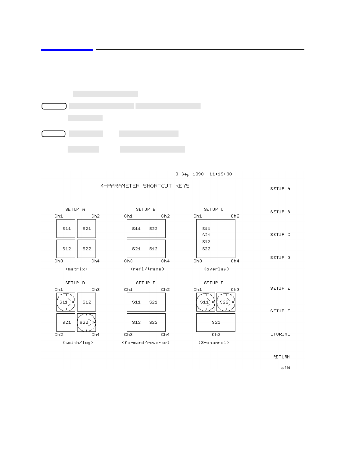
Quick Four-Parameter Display Setup
To quickly set up a four-parameter display, you can use the 4-PARAMETER SHORTCUT KEYS
menu to set up a choice of common configurations.
To use the menu to quickly set up a four-parameter display, press:
Display
Pressing brings up a screen which color-codes each channel to the keys which
TUTORIAL
affect it. For example, in Setup A, channel 1 is shown in yellow as well as the keys
Chan 1
, ,and . Pressing all ofthe keys listed below Setup
A in order from top to bottom achieves the same results (four-parameter display) as
pressing in the menu.
Figure 1 4 Parameter Displays Menu
4

Measurement Examples
LOGMAG
DUAL|QUAD SETUP
DUAL CHAN on OFF
ON
AUX CHAN on OFF
ON
SPLIT DISP
4X
Measurement Examples
Displaying All Four S-Parameters of a Two-Port Device
This measurement example demonstrates how to display all four S-parameters of a
two-port device. (If you are using an HP 8753E Option 011, you must have an S-parameter
test set connected to your analyzer.) In this example, the device to be tested is a bandpass
filter with a center frequency of 134 MHz.
NOTE The measurement examples in this supplement use a two-port calibration
covering the entire range of the analyzer, then narrowed to the range of the
DUT using interpolated error correction.
1. Press .
Preset
2. Connect the DUT to the analyzer.
3. Set the format type for the DUT. This example uses format.
4. If channel 1 is not active, make it active by pressing .
5. Press . Set to ,
Display
Chan 1
to , and to .
The display will appear as shown in Figure 2, “Three-Channel Display,” on page 6.
Channel 1 is in the upper left-hand quadrant of the display, channel 2 is in the upper
right-hand quadrant, and channel 3 is in the lower half of the display.
Notice that the default S-parameters are: S
channel 3. These can be changed by making a channel active, then pressing and
for channel 1; S21 for channel 2; and S12 for
11
Meas
selecting a different S-parameter for the channel.
5

Measurement Examples
Figure 2 Three-Channel Display
6
Measurement Examples
AUX CHAN on OFF
ON
6. Press and set to .
Chan 2
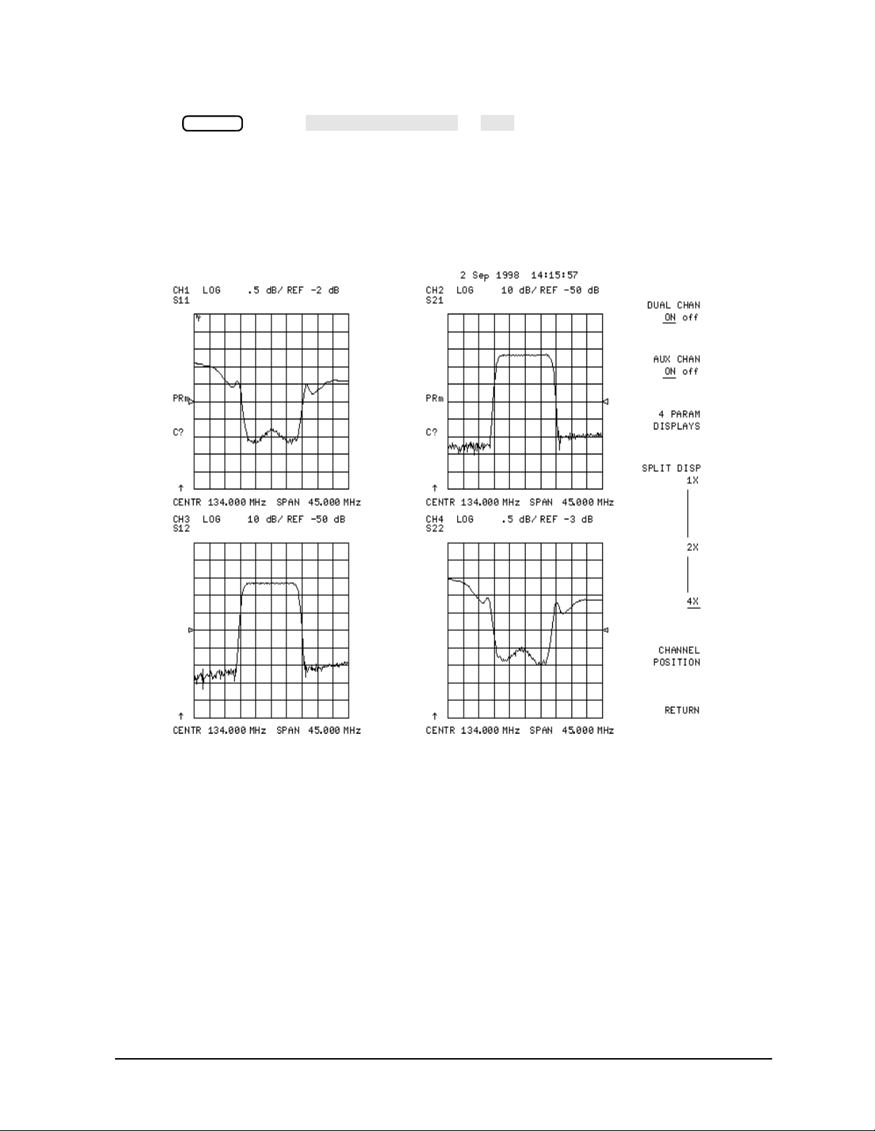
This enables channel 4, and the screen now displays four separate graticules as shown
in Figure 3. Channel 1 is in the upper left-hand quadrant of the display, channel 2 is in
the upper-right, channel 3 is in the lower-left, and channel 4 is in the lower-right.
Figure 3 Four-Channel Display
7

Measurement Examples
MARKER 1
MARKER 2
MARKER MODE MENU
MARKERS COUPLED UNCOUPLED
UNCOUPLED
Activate the Auxiliary Channels
7. Press .
The amber LED adjacent to the hardkey flashes. This indicates that channel 4
Chan 2
Chan 2
is now active and can be configured.
8. Press and .
Marker
Markers 1 and 2 appear on all four channel traces and can be moved using the front
panel control knob.
9. Press .
The LED is constantly lit, indicating channel 1 is active. Press again and
Chan 1
Chan 1
notice that the LED flashes, indicating that channel 3 is active.
10.Rotate the front panel control knob.
Notice that marker 2 moves in all four channels.
Uncouple the Display Markers
11.Press .
Marker Fctn
Set to .
12.Rotate the front panel control knob.
Notice that marker 2 moves only on channel 3. If you activate another channel and
rotate the control knob, the marker will move only in that channel.
8

Measurement Examples
COUPLED CH on OFF
OFF
TTL I/O
TTL OUT
TESTSET I/O FWD
TESTSET I/O REV
CALIBRATE MENU
FULL 2-PORT
TTL I/O
TTL OUT
TESTSET I/O FWD
TESTSET I/O REV
CALIBRATE MENU
FULL 2-PORT
Characterizing a Duplexer
This measurement example demonstrates how to characterize a 3-port device, in this case
a duplexer, using four-parameter displaymode.(If you are using an HP 8753E Option 011,
you must have an S-parameter test set connected to your analyzer.) You must use a test
adapter to route the signals from the analyzer (a two-port instrument) to the duplexer (a
three-port device). This example procedure is performed using an 8753E and one of the
following test adapters:
❏ HP 8753D Option K36 duplexer test adapter
❏ HP 8753D Option K39 3-port test adapter
1. Press .
Preset
2. Connect the test adapter to the analyzer according to the instructions for your
particular model. Connect any test fixture or cables to the duplexer test adapter.
3. Set up channel 1 for the Tx-Ant stimulus parameters (start/stop frequency, power level,
IF bandwidth).
4. Uncouple the primary channels from each other:
Press , then set to .
Menu
5. Set up control of the test adapter so that channel 1 is Tx:
Press
7 x1
Seq
.
7 x1
6. Perform a full 2-port calibration on channel 1 (refer to the user’s guide if necessary).
Press .
Cal
NOTE Make sure you connect the standards to the Tx port of the test adapter (or a
cable attachedto it) for the FORWARD calibration, and tothe Ant port for the
REVERSE calibration.
7. Press .
Chan 2
8. Set up channel 2 for the Ant port-to-Rx port stimulus parameters.
9. Set up control of the test adapter so that channel 2 is Rx:
Press
6 x1
10.Perform a full 2-port calibration on channel 2 (refer to the user’s guide if necessary).
Press .
NOTE Make sure you connect the standards to the Rx port of the test adapter (or a
Seq
6 x1
.
Cal
cable attachedto it) for the FORWARD calibration, and tothe Ant port for the
REVERSE calibration.
9

Measurement Examples
DUAL|QUAD SETUP
DUAL CHAN on OFF
ON
AUX CHAN on OFF
ON
AUX CHAN on OFF
ON
SAVE STATE
CONFIGURE MENU
TESTSET SW CONTINUOUS
CONFIGURE MENU
TESTSET SW CONTINUOUS
11.Connect the DUT to the test adapter.
12.To set up a 2-graticule, 4-parameter display with Tx-Ant measurements on the top
graticule and Ant Rx measurements on the bottom graticule, perform the following:
• Press , then set to .
Display
• to
• Press .
Chan 1
• to
13.Save this state in the analyzer by pressing .
Save/Recall
14.The display will be similar to Figure 4.
Normally, a 2-port calibration requires a forward and reverse sweep to complete before
the displayed trace updates. For faster tuning, it is possible to set the number of sweeps
for the active display (S11 and S21 for channel 1) to update more often than the unused
parameters. In this example we chose 8 updates of the forward parameters to 1 update
of the reverse channel 1, and 8 updates of the reverse to 1 update of the forward in
channel 2 (where the active parameters are S
Press .
Press .
Chan 1 System
Chan 2 System
and S12).
22
8 x1
8 x1
10
 Loading...