

REFLECTION
TRANSMISSION
Agilent 8712B and 8714B
RF Economy Vector
Network Analyzers
Data Sheet
8712B, 300kHz to 1.3 GHz
8714B, 300kHz to 3.0 GHz

Specifications
Measurement ports
8712B 8714B
50 and 75 ohm
Directivity 40 dB 40 dB
Source match 20 dB 20 dB
(reflection)
Source match 14 dB typical
1
23 dB typical at < 1.3 GHz,
(transmission) 20 dB typical at >1.3 GHz
Load match 18 dB typical 20 dB typical at <1.3 GHz,
18 dB typical at >1.3 GHz
Reflection Tracking 0 +0.4 dB typical 0 +0.2 dB typical
This table shows the residual Agilent Technologies 8712B and 8714B
system specifications. These characteristics apply at an environmental
temperature of 25° ±5° C, with less than 1° C deviation from the calibration temperature. Directivity and source match specifications apply
Source
Frequency
Range 300 kHz to 1.3 GHz (8712B)
300 kHz to 3.0 GHz (8714B)
Resolution 1 Hz
Stability +5 ppm 0˚ C to 55˚ C (typical)
Accuracy 1) +5 ppm at 25˚ C +5˚ C
2) <1 Hz at 10% change in line voltage
Harmonics <-20 dBc, <1MHz
<-30 dBc, >1MHz for 8712B
<-30 dBc for 8714B
Output Power
Resolution 0.01 dB
Level accuracy +1.0 dB
+1.5 dB Option 1EC
1
+2.0 dB Option 1E1
+3.0 dB Option 1EC1amd 1E1
Maximum and Minimum Power
8712 B 8714B
≤1.0 GHz >1.0GHz
Options minimum maximum minimum maximum minimum maximum
power power power power power power
No options 0 dBm 16 0 13 -5 10
1E1 -60 15 -60 12 -60 9
1EC
1
-3 13 -3 10 -8 7
1DA/DB -2 14 -2 11 -9 6
1E1 and 1EC
1
-60 12 -60 9 -60 6
1E1 and 1DA -60 13 -60 10 -60 5
1EC1and 1DB -5 11 -5 8 -12 3
1EC1, 1E1 and 1DB -60 10 -60 7 -60 2
1. All power specifications with Option 1EC (75 ohms) are typical above 2.0 GHz.
2
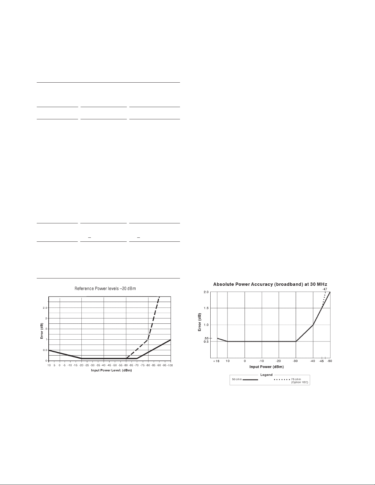
3
Receiver
Frequency range 8712B 8714B
Narrowband 300 kHz 300 kHz
to 1.3 GHz to 3.0 GHz
Broadband 0.10 to 1.3 GHz 0.10 to 3.0 GHz
Dynamic range
2
Narrowband >100 dB, ≥5 MHz
50 ohm (+10 to -90 dBm) >100 dB
>60 dB <5 MHz (+10 to -90 dBm)
(+10 to -50 dBm)
Narrowband >97 dB, >5 MHz >97 dB
75 ohm (+10 to -87 dBm) (+10 to -87 dBm)
>57 dB, <5 MHz
(+10 to -47 dBm)
Broadband
50 ohm >66 dB <66 dB
(+16 to -50 dBm) (+16 to -50 dBm)
75 ohm >63 dB >63 dB
(+16 to -47 dBm) (+16 to -47 dBm)
Damage level +23 dBm, +23 dBm,
+25 VDC +25 VDC
Maximum input
Narrowband +10 dBm +10 dBm
(0.5 dB compression)
Broadband +16 dBm +16 dBm
(0.55 dB compression)
2. Receiver dynamic range is calculated as the difference between maximum receiver input level and receiver’s noise floor. System dynamic range applies to transmission measurements only, since reflection measurements are limited by directivity. Noise floor is specified as the mean trace noise at specified CW frequencies. A signal at this level
would have a signal to noise ratio of 3 dB. Noise floor is measured with test ports terminated in loads, response and isolation calibration, 15 Hz IF bandwidth, 10 dB source
power and no averaging.

4
AM Delay (Option 1DA/1DB)
This option adds amplitude modulation group
delay capability, which allows measurements of
group delay through frequency-translation devices
such as tuners or mixers. Using two external scalar
detectors (86200B or 86201B) and a power splitter
(all included) this option measures group delay in
any device that does not have limiting circuits, saturated amplifiers, or automatic gain control.
Aperture 55.56 kHz
Resolution 1 ns /division
Accuracy
3
±4 ns
Delay range 30 µsec, (9000 m)
Amplitude range –10 to +13 dBm (typical)
Power Delay
0 to 10 dB ±10 ns
10 to 20 dB ±20 ns
AM Delay Dynamic Accuracy (typical)
4
Group Delay
Group delay is computed by measuring the phase
change within a specified frequency step (determined by the frequency span, and the number of
points). This is also known as d(phi)/d(omega).
Aperture
Maximum aperture: 20% of frequency span
Minimum aperture: (frequency span) /
(number of points –1)
Range
The maximum delay is limited to measuring no
more than 180° of phase change within the minimum aperture. Range = 1 / (2 x minimum aperture)
Accuracy
The following graph shows group delay accuracy at
1.3 GHz with type-N transmission calibration and
15 Hz IF bandwidth. Insertion loss is assumed to
be <2 dB and electrical length to be ten meters.
3. Specified at 0 dBm, 16 averages, well-matched device, normalized.
4. Normalized at +10 dBm.
Group Delay
Group Delay Accuracy
Frequency = 1.3 GHz Electrical Length = 10 meters
100
10
1
.1
Uncertainty - nsec
.01
.01
.01
.1
1
Aperture - MHz
10 100

5
Source Signal Purity
Nonharmonic spurious Agilent 8712B Agilent 8714B
≥50 kHz from carrier <–20 dBc, <1 MHz <–30 dBc
<–30 dBc, ≥1 MHz
<50 kHz from carrier <–25 dB <–25 dBc
Phase noise –70 dBc/Hz –67 dBc/Hz
(at 10 kHz offset)
Residual AM <–50 dBc <–50 dBc
(in 100 kHz bandwidth)
Residual FM <1.5 kHz <1.5 kHz
30 Hz to 15 kHz peak peak
Display Characteristics
Amplitude
Display resolution 0.01 dB/division
Marker reference level range: ±500 dB
resolution: 0.01 dB
Phase
Range ±180°
Display resolution 0.1°/division
Marker resolution 0.01°
Reference level range ±360°
resolution 0.01°
Polar scale range 1m to 20/division
Typical measurement uncertainty for 8714B at 1.3 GHz
Transmission magnitude uncertainty
Transmission phase uncertainty
Reflection magnitude uncertainty
Reflection phase uncertainty
These graphs show the measurement uncertainty for the 8714B. The assumptions made to generate these curves were: for transmission
uncertainty, S
1
1
= S22= 0.0; and for the reflection uncertainty, S21 =S12 = 0.0. Reflection tracking = 0.3 dB, transmission tracking =
0.2704 dB (computed from match terms), and trace noise = 0.250 dB. Power = 0 dBm for reflection measurements, and –20 dBm for
transmission measurements.
Supplemental Data

6
Measurement
Number of display channels
Two display channels are available.
Measurements
• Narrowband: reflection (A/R), transmission
(B/R), A, B, R
• Broadband: X, Y, Y/X, X/Y, Y/R*, power (B*, R*),
conversion loss (B*/R*)
Formats
• Rectilinear: log or linear magnitude, phase,
group delay, SWR, real and imaginary, and dBv,
dBmv and dBuv (75 ohm only)
• Smith chart
• Polar
Data markers
Each display channel has eight markers. Markers
are coupled between channels. Any one of eight
markers can be the reference marker for delta
marker operation. Annotation for up to four markers
can be displayed at one time.
Marker functions
Markers can be used for various functions: marker
search, mkr to max, mkr to min, mkr Æ target, mkr
bandwidth and notch. Also with user-defined target
values, mkr Æ center, mkr Æ reference, mkr Æ
electrical delay are available. The tracking function
enables continuous update of marker search values
on each sweep. For testing cable TV broadband
amplifiers, the slope and flatness functions enable
rapid tuning. Marker statistics enable measurement of the mean, peak-to-peak and standard deviation of the data between two markers.
Storage
Internal memory
400 Kbytes of nonvolatile storage is available to
store up to 100 instrument states via the
save/recall menu. Instrument states can include all
control settings, active limit lines, memory trace
data, active calibration coefficients, and custom
display titles.
Disk drives
Data, instrument states (including calibration
data), and IBASIC programs can also be stored on
disk, using the built-in disk drive or an external
disk drive with command subset CS/80. Data can
be stored to disk in MS-DOS (R) format or Agilent’s
standard LIF format. Data can be stored in binary,
PCX, HP-GL or ASCII formats.
Data Hardcopy
Data plotting
Hard copy plots are automatically produced with
HP-GL compatible digital plotters such as the
Agilent 7475A and compatible graphics printers
such as the HP DeskJet or LaserJet (in single color
or multi-color format). The analyzer provides
Centronics, RS-232C, and GPIB interfaces.
Data listings
Printouts of instrument data are directly produced
with a printer such as the HP DeskJet 540 or 560C
or PaintJet 3630A (color).
CRT formats
Single-channel, dual-channel overlay (both traces
on one graticule) or dual-channel split (each trace
on separate graticules).
Trace functions
Display current measurement data, memory data
or current measurement with memory data simultaneously. Vector division of current linear measurement values and memory data.
Display annotations
Start/stop, center/span, or CW frequency,
scale/division, reference level, marker data, soft
key functions, warning and caution messages,
titles, clock and pass/fail indication.
Limit lines
Create test limit lines that appear on the display
for pass/fail testing. Limits may be any combination of lines or discrete points. Limit test TTL output available for external control or indication.
Limit lines are only available in rectilinear formats.
Remote Programming
Interface
GPIB interface operates to IEEE 488.2 and SCPI
standard interface commands.
Pass control
Allows the analyzer to request control of the GPIB
(when an active controller is present) output to a
plotter or printer.
System controller
Lets the analyzer become the controller on the
GPIB bus to directly control a plotter or a printer.
Data transfer formats
• Binary (internal 48-bit f loating point complex
format)
• ASCII
• 32- or 64-bit IEEE 754 floating point format
• Mass memory transfer commands allow file
transfer between external controller and analyzer.
Characteristics

7
Determining Optional Sweep Speed and
Dynamic Range
Dynamic range, sweep time and IF Bandwidth are
interdependent quantities. Reducing sweep time
usually results in a decrease in dynamic range. A
compromise must be made depending upon the
application. The following charts will help in making these tradeoffs. All data determined from preset conditions, except as noted.
Agilent 8714B dynamic range vs IF BW (typical)
IF bandwidth Narrowband dynamic range
Wide (6500 Hz) 70 dB typical
Medium (3700 Hz) 90 dB typical
Narrow (250 Hz) 105 dB typical
Fine (15 Hz) 110 dB typical
Measurement sweep times (msec)
8712B 8714B
fwd cycle fwd cycle
Medium IF BW 132 159 182 223
Wide IF BW 64 72 118 159
CF = 177 MHz, 51 59 68 87
Span = 200 MHz
Determining Automated Test Configuration
The following charts are provided to assist in
deciding upon system configurations when
automating test systems. Typical tradeoffs are
between transferring data to an external computer
or utilizing the built-in IBASIC capabilities.
Speed of common IBASIC operations (in microseconds)
Platform
Operation 871X 80486DX
IBASIC 33 MHz
int16 ADD 182 35
int16 SUB 200 36
int16 MUL 219 39
int16 DIV 860 124
float64 ADD 366 94
float64 SUB 346 93
float64 MUL 384 92
float64 DIV 502 95
Trace transfer time (in milliseconds)
Number of points
Format 51 201 401 1601
Corrected (Int, 16) 26 31 39 85
Corrected (Real, 64) 32 65 97 330
Corrected (ASCII) 105 364 713 3000
Formatted (Real, 64) 38 59 98 335
Formatted (ASCII) 60 199 390 1510
Entering 8711 data into a BASIC workstation (735/125)
Number of points
Format 51 201 401 1601
Corrected (Real, 64) 32 65 97 330
Formatted (Real, 64) 38 59 98 335
Entering data from IBASIC
Number of points
Format 51 201 401 1601
Corrected (Int, 16) 28 30 38 102
Corrected (Real, 32) 38 100 182 675
Corrected (Real, 64) 36 90 161 593
Corrected (ASCII) 130 470 923 3600
Formatted (Real, 64) 28 60 102 354
Formatted (ASCII) 75 254 492 1900
Entering 8711 data into a PC (HP Vectra VL2 4/66)
8712B/8713B block diagram
Characteristics
Y
Input B
Input B*
X
Input R
Input R*
Input A
External Detectors
X
Reference
Reflected
RF Out
RF
Source
Y
Incident
Under Test
Trnsmitted
RF In
Device
AUX Input
REAR PANEL
To Processor and Display
CRT
FRONT PANEL
= Narrowband Detector
= Broadband Detector

8
Measurement Calibration
Calibration significantly reduces measurement
uncertainty due to errors caused by system directivity, source match, reflection tracking and
crosstalk. These analyzers reduce systematic errors
with a built-in calibration so that measurements
can be made on many devices without performing
a user calibration. For greater accuracy, especially
for special test setups, the analyzers offer one-port
reflection calibration to remove reflection errors, a
response calibration to remove transmission tracking error and a response and isolation calibration
to remove transmission tracking and crosstalk
errors.
The interpolated mode recalculates the error coefficients when the test frequencies or the number of
points are changed. The resulting frequency span
must be equal to or less than the user calibration
frequency span. System performance is not specified for measurements with interpolated error correction applied.
Calibrations Available
Transmission measurements
Normalization
Simultaneous magnitude and phase correction of
frequency response errors for transmission measurements. Requires a through connection. Used for
both narrowband and broadband measurements.
Does not support interpolation.
Response
Simultaneous magnitude and phase correction of
frequency response errors for transmission measurements. Requires a through connection.
Response and isolation
Compensates for frequency response and crosstalk
errors. Requires a load termination on reflection
and transmission ports and a through connection.
Reflection measurements
One-port calibration
Calibrates reflection port to correct directivity,
tracking and source match errors. Requires an
open, short, and load.
Calibration Kits
Data for several standard calibration kits are
stored in the instrument for use by calibration routines. They include:
• 3.5 mm (choose 85033C or 85033D)
• type-F 75 ohm (choose 85039A)
• type-N 50 ohm (choose 85032B/E)
• type-N 75 ohm (choose 85036B/E)
In addition you can also describe the standards
(for example, open-circuit capacitance coefficients,
offset short length, or fixed loads) of a userdefined kit.
The following calibration kits available from
Agilent contain precision standards in many different connector types. For further information, consult the RF Economy Network Analyzer
Configuration Guide, literature number 59629928E.
85032B/E 50 ohm type-N calibration kit
Contains precision 50 ohm type-N standards used
to calibrate the analyzer to measure devices with
50 ohm type-N connectors. E versions do not contain adaptors or female standards.
85036B/E 75 ohm type-N calibration kit
Contains precision 75 ohm type-N standards to calibrate the analyzer to measure devices with 75
ohm type-N connectors. E versions do not contain
adaptors or female standards.
85039A type-F calibration kit
Contains 75 ohm type-F standards to calibrate the
analyzer to measure devices with type-F connectors.
85033D Option 001 3.5 mm calibration kit
Contains precision 3.5 mm standards to calibrate
the analyzer to measure devices with 3.5 mm or
SMA connectors.
Calibration

9
Standard Options
75 ohms (Option 1EC)
Provides 75 ohm system impedance.
AM delay (Option 1DA/1DB)
This option adds amplitude modulation group
delay capability, which allows measurements of
group delay through frequency-translation devices
such as tuners or mixers. Using two external scalar
detectors (86200B or 86201B) and a power splitter
(all included) this option measures group delay in
any device that does not have limiting circuits, saturated amplifiers, or automatic gain control.
Option 1DA is for a 50 ohm 8712B or 8714B.
Option 1DB is for a 75 ohm 8712B or 8714B.
IBASIC (Option 1C2)
This option adds a resident BASIC system controller, facilitating automated measurements and
control of other devices. Using keystroke recording
for the simplest applications, or an optional keyboard to write complex control and calculation
programs, IBASIC improves productivity by customizing your measurements.
Step attenuator (Option 1E1)
This option adds a built-in 60 dB step attenuator,
extending the source output power low-end range
to –60 dBm.
Fault location and structural return loss software (Option
100)
For fully characterizing cable performance, this
software package provides both fault location and
structural return loss. Structural return loss is a
special case of return loss measurements. Physical
damage of cable, by handling or manufacturing
process, causes reflections. Structural return loss
occurs when these periodic reflections sum at halfwavelength spacing and reflect the input signal.
Special Options
Switching test sets (Special Option K02)
Switching test sets enhance productivity by allowing multiple measurements with a single connection to the device under test. They are available in
several configurations. Please call the factory for
more information.
Options

Front panel connectors
Connector type type-N female
Impedance 50 ohms (standard)
75 ohms (Option 1EC)
Probe power +15V 200 mA
-12.6V 250 mA
Rear panel connectors
External reference 10 MHz, > –5 dBm,
50 ohm BNC
Auxiliary input
The auxiliary input measures the DC level at each
sweep point. If the slew rate on this input exceeds
700 mV/msec, increased measurement errors will
result.
Calibrated range ±10V
Accuracy ±(3 % of reading +20 mV)
Damage level >15 Vdc
External trigger
Triggers on a negative TTL transition or contact
closure to ground.
Limit test output
Provides an open collector TTL high signal. The
output is pulled low when the limit test fails.
User TTL input/output
Provides a bi-directional open collector TTL signal
that can be accessed by IBASIC.
Video output
Provides an RS-343A compatible multisync video
signal. Pixel rate is 33.3 MHz, vertical rate is 60 Hz,
and horizontal rate is 24.1 kHz. Output is not compatible with EGA or VGA monitors.
GPIB
Allows communications with compatible devices
including external controllers, printers, plotters,
disk drives, and power meters.
X and Y external detector inputs
Provides for two external detector inputs. See
Agilent 86200B and 86201B Data Sheet, literature
number 5962-9931E.
Parallel port
This 25-pin female connector is used with parallel
(or Centronics interface) peripherals such as printers and plotters. It can also be used as a generalpurpose I/O port, with control provided by IBASIC.
RS-232C
This 9-pin male connector is used with serial
peripherals such as printers and plotters.
DIN keyboard
This connector is used for adding an IBM PC-AT
compatible keyboard for titles, remote front-panel
operation, and for IBASIC programming (Option
1C2).
Liner
47 to 60 Hz
115V nominal (90V to 132V) or 230V nominal
(198V to 264V) 230 VA max. A three-wire ground is
required.
Environmental Characteristics
General conditions
RFI and EMI susceptibility defined by CISPR
Publication 11.
ESD (electrostatic discharge) should be minimized
by the use of static-safe work procedures and an
antistatic bench mat (such as a 92175T).
The sealed flexible rubber keypad protects key contacts from dust, but the environment should be as
dust-free as possible for optimal reliability.
Operating environment
Temperature 0° to 55° C
Humidity 5% to 95% at 40° C
(noncondensing)
Altitude 0 to 4,500 meters (15,000 feet)
Storage conditions
Temperature –40° C to +70° C
Humidity 0 to 90% relative at +65° C
(noncondensing)
Altitude 0 to 15,240 meters (50,000 feet)
Cabinet dimensions
The following dimensions exclude front and rear
panel protrusion:
179 mm H x 425 mm W x 514 mm D
(7.0 in x 16.75 in x 20.25 in)
Weight
Net 20.5 kg
Shipping 30 kg
10
General Characteristics

11
This document describes the system performance of
the 8712B and 8714B 50 ohm and 75 ohm (Option
1EC) network analyzers, and provides two kinds of
information:
Specifications describe the instrument’s warranted
performance over the temperature range of 25° ±5°C,
unless otherwise stated.
Supplemental characteristics are typical but nonwarranted performance parameters. These are
denoted as “typical,” “nominal” or “approximate.”
Test hardware includes the following:
Network analyzer: 8712B or 8714B
Calibration kit: 85032E (50 ohm)
85036E (75 ohm)
Test port cable: part number 8120-6469 (50 ohm)
part number 8120-6468 (75 ohm)

Agilent Technologies’ Test and Measurement
Support, Services, and Assistance
Agilent Technologies aims to maximize the value you receive,
while minimizing your risk and problems. We strive to ensure
that you get the test and measurement capabilities you paid
for and obtain the support you need. Our extensive support
resources and services can help you choose the right Agilent
products for your applications and apply them successfully.
Every instrument and system we sell has a global warranty.
Support is available for at least five years beyond the production life of the product. Two concepts underlie Agilent’s
overall support policy: “Our Promise” and “Your Advantage.”
Our Promise
“Our Promise” means your Agilent test and measurement equipment will meet its advertised performance and functionality.
When you are choosing new equipment, we will help you with
product information, including realistic performance specifications and practical recommendations from experienced test
engineers. When you use Agilent equipment, we can verify that
it works properly, help with product operation, and provide
basic measurement assistance for the use of specified capabilities, at no extra cost upon request. Many self-help tools are
available.
Your Advantage
“Your Advantage” means that Agilent offers a wide range of
additional expert test and measurement services, which you
can purchase according to your unique technical and business
needs. Solve problems efficiently and gain a competitive edge
by contracting with us for calibration, extra-cost upgrades, outof-warranty repairs, and on-site education and training, as well
as design, system integration, project management, and other
professional services. Experienced Agilent engineers and technicians worldwide can help you maximize your productivity,
optimize the return on investment of your Agilent instruments
and systems, and obtain dependable measurement accuracy
for the life of those products.
By internet, phone, or fax, get assistance with all your
test and measurement needs.
Online Assistance
www.agilent.com/find/assist
Phone or Fax
United States:
(tel) 1 800 452 4844
Canada:
(tel) 1 877 894 4414
(fax) (905) 206 4120
Europe:
(tel) (31 20) 547 2323
(fax) (31 20) 547 2390
Japan:
(tel) (81) 426 56 7832
(fax) (81) 426 56 7840
Latin America:
(tel) (305) 267 4245
(fax) (305) 267 4286
Australia:
(tel) 1 800 629 485
(fax) (61 3) 9272 0749
New Zealand:
(tel) 0 800 738 378
(fax) (64 4) 495 8950
Asia Pacific:
(tel) (852) 3197 7777
(fax) (852) 2506 9284
Product specifications and descriptions in this
document subject to change without notice.
Copyright © 1995, 2000 Agilent Technologies
Printed in U.S.A. 6/00
5964-0112E
 Loading...