


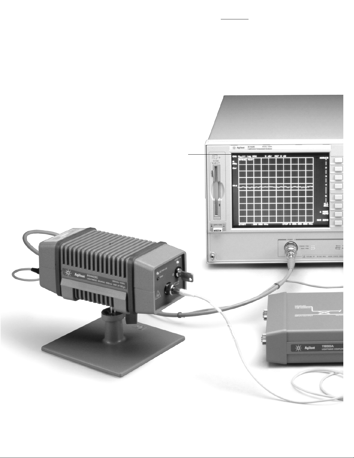
Agilent 8702E
Lightwave Component Analyzer
850 nm, 1300 nm, 1550 nm
300 kHz to 3 or 6 GHz
Product Overview
Accurate modulation frequency response measurements
of lightwave components
2
Measurement versatility by design
Lightwave coupler
For measuring
optical return loss
and locating discontinuities.
Agilent 11890A,
single-mode (9/125 um)
Lightwave source
A stable, calibrated laser source with
high modulation bandwidth and large dynamic range.
Agilent 83402C, 1300 nm, single-mode (9/125 µm), 300 kHz to 6 GHz, DFB
Agilent 83403C, 1550 nm, single-mode (9/125 µm), 300 kHz to 6 GHz, DFB
Guided measurements
Fast, easy measurements
without intensive training.

3
Electrical, optical, and electro-optical calibrations
Accurate, repeatable measurements of all the components of a fiber
optic system.
System
Provides access to limit testing, swept harmonic measurements
(option 8702E-002), time domain analysis, and other special functions.
Copy
Send measurement results to plotter or printer over the GPIB, parallel,
or serial interface.
Save/Recall
Save and recall test sequences, measured data, calibration data, and
instrument states internally or with the built-in disk drive.
Sequencing
Internally configure and automate measurements with test
sequencing, an enhanced form of keystroke recording.
Versatile configuration
Integrated S-parameter test set provides complete forward and
reverse measurements in 50 ohms or 75 ohms (with option
8702E-075). For flexibility in test set configuration, you can delete the
built-in test set (with option 8702E-011) and select your own test set
(compatible with Agilent 85046A and 85047A.)
Lightwave receiver
Calibrated, high modulation
bandwidth, photodiode receiver.
Agilent 83410C, 1300 and 1550 nm, SMF and MMF, 300 kHz to 3 GHz, amplified
Agilent 83411C, 1300 and 1550 nm, SMF, 300 kHz to 6 GHz
Agilent 83411D, 1300 and 1550 nm, SMF, 300 kHz to 6 GHz, amplified
Agilent 83412B, 850 nm, SMF and MMF, 300 kHz to 3 GHz, amplified
Internal synthesized
RF source
Provides accurate
modulation frequencies,
sweeping 300 kHz
to 3 GHz and optionally
6 GHz (option 8702E-006).

4
Measurements across the system
Modern lightwave transmission systems require accurate and repeatable characterization of their electrooptical, optical, and electrical components to guarantee high-speed performance. The Agilent 8702E lightwave component analyzer improves the design and specification of these lightwave components.
It operates by analyzing a swept frequency signal modulating a 1300 or 1550 nm optical carrier.
With the capabilities of the Agilent 8702E you can:
■
Characterize component bandwidths with modulation frequencies to 3 GHz (6 GHz optionally).
■
Isolate laser and photodiode response with calibrated transmitter and receiver measurements.
■
Accurately measure electrical return loss of photodiodes, lasers, connectors, and other lightwave components.
■
Measure the swept frequency response of modulation second and third harmonics.
■
Locate reflections and view step response with distance/time domain measurements.
System Operation
The 8702E consists of an RF
source that provides a known
swept, synthesized modulation
signal, and a receiver that
measures the magnitude and
phase of the returned RF signal.
To measure a lightwave device,
the RF source of the 8702E
provides a modulation signal to an
external lightwave source, which
provides a modulated light signal
to the optical device. An external
lightwave receiver module demodulates the lightwave signal after it
passes through the optical device
under test. The demodulated RF
signal is passed to the receiver of
the 8702E where the magnitude
and phase response of the signal
is measured. With this system,
the transfer function of the test
device is determined as a function
of modulation frequency.
Often the limiting elements in a
fiber optic transmission system
are the electro-optical components (e.g. lasers, APDs, PIN
photodiodes, and, modulators)
which convert the electrical
information to optical or vice
versa. With the 8702E, calibrated
measurements of modulation
bandwidth, responsivity, and
modulation range of an individual transducer are possible.
Electro-optical components
Electrical components
Optical components
Optical components such as fiber,
connectors, splitters, couplers,
and lenses make up much of a
fiber optic network. The 8702E
measures the modulation bandwidth, insertion loss, length and
optical return loss of these
components. Reflections can be
located and the step response of
a component viewed with the
time domain feature.
Linear electrical components
such as amplifiers, filters, and
transmission lines are used in
fiber optic systems. They also
require characterization to ensure
optimal performance. Typically
the bandwidth, insertion loss/
gain, insertion phase, impedance,
match and group delay are
required measurements.
Demodulated
Result
Modulated
Light
RF
In
Optical
Device
RF
Out

5
123456
–1
–0.8
–0.6
–0.4
–0.2
0
0.2
0.4
0.6
0.8
1
Frequency (GHz)
Normalized Calibration Data (dBe)
NIST
Agilent Production System
300 kHz
0123456
–3
–2
–1
0
1
GHz
dB
Response Cal
Response & Match Cal
The Agilent 83400 family of lightwave sources and
receivers offer wide bandwidth, stability, and
dynamic range. Each receives an individual, NIST
traceable calibration which significantly improves
measurement accuracy of your electro-optical
devices. The density of calibration data points has
been increased at low modulation frequencies.
The 8702E combines the convenience of calibrated
lightwave measurements with all the RF measurement capability of the Agilent 8753ES RF network
analyzer. Following are a few of the new capabilities
and improvements.
■
Integrated RF test set provides complete forward
and reverse S-parameter measurements with a
single connection.
■
Built-in disk drive with LIF/DOS formats allows
convenient storage of instrument states, data, and
test sequences.
■
Serial and parallel interfaces for support of a wide
selection of printers and plotters.
■
Faster operation 67% faster CPU clock rate provides
faster error correction, time domain calculations,
and data transfers.
■
Real time clock for convenient time-stamping of
data printouts and files.
■
Improved electrical performance from 3 to 6 GHz
Wider output power range (–85 to +10 dBm
standard) and dynamic range (110 dB to 3 GHz
and 105 dB to 6 GHz.)
■
More non-volatile memory
Internal storage of calibration data, as well
as a maximum of 32 instruments states.
■
Test sequencing 8702E stores keystrokes for
automation without external computer control.
■
Harmonic measurement capability
Characterize your amplified opto-electric
component’s swept 2nd and 3rd harmonic
response absolutely, or in dBc (dB below carrier.)
Lightwave sources and receivers for improved measurement accuracy
A response calibration allows the 8702E to remove
the response of the test system, including the electrical cables, optical fiber, the lightwave source and
receiver, and the analyzer itself for the highest
measurement accuracy. The new response/match
calibration improves measurement accuracy for O/E
and E/O devices with non-ideal electrical match.
New lightwave response/match calibration
New RF features provide more performance and value

6
Electro-optical
component measurements
E/O modulation bandwidth
Responsivity (∆Po/∆I)
O/E demodulation bandwidth
O/E transducer responsivity at several different
levels of optical attenuation
Characterize modulation
transfer functions
In any lightwave
system, it is difficult to measure
the modulation
response of a
laser independently from a
photodiode, and
vice versa. Unlike any other
system, the 8702E can independently measure the modulation
transfer function of electrooptical transducers. Modulation
bandwidth, flatness, and phase
linearity can also be determined.
Lasers, LED’s, modulators, and
photodiodes can be measured,
and an absolute value assigned
to the responsivity.
Responsivity measurements
Signal energy enters a lightwave
system through a laser and exits
through the photodiode. To determine signal noise and system loss
budgets, it is important to know
how much signal energy a laser
or photodiode transmits. The
8702E measures this when it
measures modulation transfer
function of E/O and O/E devices.
This quantity is called responsivity, and is measured in a 50
ohm electrical environment.
Responsivity is the ratio of optical
modulation power to electrical
current for an E/O transducer
(laser, LED), and the inverse for
an O/E transducer (photodiode).
Dynamic range
By adding a variable attenuator,
the 8702E can
be used to
measure the
dynamic range
of an O/E trans-
ducer (photodiode). The 8702E can measure the
linearity and noise of a receiver
over as much as a 100 dB range.
In this example, an Agilent 8347A
RF amplifier was used to boost
the electrical signal from the lightwave receiver, extending the
dynamic range of the system.
RF
E/O
Out
RF
In
O/E
Intensity
P
o
∆P
∆I
o
Current I
RF
In
Agilent 8156A
Optical
Attenuator

7
Electrical component measurements
Electrical measurements
The 8702E will
measure the
transfer function
and impedance of
electrical devices
with unparalleled
accuracy.
Typical transfer
function measurements include
the loss, gain, linearity, flatness,
phase, group delay, and length of
the test device.
Impedance measurements show
match, return loss, reflection
coefficient, SWR, and
complex impedance.
High accuracy
The accuracy of these measurements comes from the high
performance hardware and from
built-in electrical measurement
calibrations.
The synthesized RF source and
high dynamic range receiver allow
the 8702E to easily measure a
wide variety of demanding
devices. The measurement calibration further improves the
accuracy by calculating systematic errors and removing them
from the measurement data.
System measurements
As well as measuring electrical
devices, the 8702E can measure
the bandwidth, insertion loss,
delay and linearity of a complete
fiber optic transmission system.
A system level measurement can
then be related back to measurements of the individual components
to allow location and improvement of the weakest elements.
Gain and group delay of a linear amplifier
Electrical
Device

Optical measurements
An 8702E
equipped with
a lightwave
source and
receiver has the
ability to characterize optical
components
as a function of modulation
frequency. Typical measurements
include bandwidth, loss, and
optical return loss.
Optical reflections
In high-speed systems, reflections
from components reduce transmitted power, cause errors in
detection, and can interfere with
the operation of a laser. The
8702E can be configured to
measure optical reflections using
an Agilent 11890 series lightwave
coupler. The 8702E’s high
dynamic range allows detection
of very small reflections.
Distance-time domain
The 8702E can calculate the step
or impulse response of
a device from its frequency
response using the inverse
Fourier transform.
Applying the time domain transform to an optical return loss
measurement allows high resolution location of reflections with
effectively no dead zone. The
8702E can resolve multiple
responses as close as 6 cm apart
(3 cm for the 6 GHz system).
The 8702E can also locate
a single response to better
than one millimeter.
8
Optical component measurements
Optical return loss of a PIN photo diode
Time domain reflection response through a distribution
panel, showing a failed splice
Optical reflection block diagram
RF
In
RF
Out
Test
Device
Lightwave
Coupler
RF
In
Optical
Device
RF
Out

Guided measurements
The 8702E will easily guide the
user through basic modulation
bandwidth and match measurements with figures and instructions on the CRT. Test setup
is simplified and made easier
to perform.
GPIB hardcopy, disc access
The 8702E can be computer
controlled over GPIB. Its serial
and parallel ports support
printers and plotters for measurement hardcopy. Data, calibrations, and instrument states can
be saved to and read from
internal memory, or the built-in
LIF/DOS disk drive.
Automate repetitive tasks
without a computer
In test sequencing mode, you
make the measurement once and
the 8702E stores the keystrokes.
Complex measurements can be
stored in a sequence and later
recalled rapidly and consistently
with the touch of a button.
Let the 8702E determine if
measurement results are within
user-defined limits. You can
choose any combination of
single-point, horizontal or sloping
line limits from the front panel.
Pass/fail is indicated on the
display, audibly, over GPIB
or from a BNC rear panel
TTL output.
User-defined frequency testing
Speed up your testing by
measuring your device at only
selected frequencies. You can
specify up to 30 arbitrary CW
frequencies or frequency sweep
segments at which to test your
device.
Change frequencies
and remain calibrated
Perform a broadband calibration
with up to 1601 points and then
adjust your frequency span or
number of measurement points
for the particular device under
test. The 8702E will use interpolation to recalculate the error terms
for the new parameters. Use this
feature to avoid recalibrating
between testing different devices.
9
All supported
by an extensive feature set
Example of “list frequency” output
Test sequence flowchart
Start
Set Stimulus
& Test Limits
Connect
Device
Measure
Parameters
Passed
Test Limits
Plot Data
& Limits
N
Tune
?
Y
Device
Y
Next
Device
Stop

10
Agilent 8702 product family
Agilent 8702E option 8702E-011 lightwave component analyzer
8702E-006 and Agilent 85047A test set extend
Agilent 8702E option 8702E-011 to 6 GHz.
Agilent 85047A S-parameter test set
Adds 6 GHz capability to Agilent 8702E
options 8702E-006 and 8702E-011.
or
Agilent 85046A S-parameter test set
For use with Agilent 8702E
option 8702E-011.
Agilent 83402C lightwave source
1,2
1300 nm, SMF (9/125 µm),
300 kHz to 6 GHz
or
Agilent 83403C lightwave source
1,2
1550 nm, SMF (9/125 µm),
300 kHz to 6 GHz
Agilent 8702E lightwave component analyzer
With integrated 50Ω test set
Option 8702E-006 extends operation to 6 GHz.
Agilent 11889A RF interface kit
Includes power splitter, 3 type-N
to SMA adapters, a 20 dB pad,
male and female SMA barrels,
3 SMA elbows, and a custom cable.
For use with the Agilent 8702E option 8702E-011.
Not required for use with
Agilent 85046A or 85047A.
Agilent 83410C lightwave receiver
1300 and 1550 nm, 300 kHz to 3 GHz
or
Agilent 83411C lightwave receiver
1300 and 1550 nm, 300 kHz to 6 GHz
or
Agilent 83411D lightwave receiver
1300 and 1550 nm, 300 kHz to 6 GHz
or
Agilent 83412B lightwave receiver
850 nm, 300 kHz to 3 GHz
1,2
1,2
1,2
1,2
Agilent 11890A
1
single-mode (9/125 µm)
lightwave coupler
1
These products have four optical connector types available. The connector option selects the type of interface adapter supplied:
81000 AI Diamond HMS 10
Option 012 FC/PC
81000 SI DIN 47256
81000 VI ST
2
A calibration disc that can be directly read by the Agilent 8702E is provided with these products. Calibration data can also be entered without a disc.

11
Options and accessories
Agilent 8702E Lightwave
component analyzer
■ 8702E-002 Add harmonic
measurement capability
■ 8702E-006 6 GHz frequency
extension
■ 8702E-011 delete test set
■ 8702E-075 75 ohm impedance
■ 8702E-110 deletes time domain
capability
■ 8702E-1D5 high stability
frequency reference
Agilent 11890A lightwave coupler
A 3 port directional coupler with
nominal coupling of 3 dB, and
34 dB nominal directivity.
Agilent 8156A optical attenuator
0 to 60 dB attenuator with
high repeatability, linearity,
and return loss.
Agilent 85046A and
85047A S-parameter test sets
The S-parameter test sets can be
used with the option 8702E-011
and provide the capability to
measure impedance and transmission characteristics (including
S-parameters) of 2 port devices in
either direction with a single
connection. The test set is
controlled from the 8702E and
includes a step attenuator. The
85047A contains 6 GHz components and is used with the Agilent
8702E options 8702E-006 and
8702E-011. The test port connectors are precision 7 mm, and the
Agilent 11857D 7 mm test port
return cables are recommended.
Agilent 11889A RF interface kit
Contains the RF accessories
needed to operate the 8702E
option 8702E-011 when a test set
is not used. Contains a power
splitter, a 20 dB pad, SMA accessories, and adapters.
Agilent 85033D 3.5 mm
calibration kit
Contains a set of precision 50 ohm
3.5 mm standards to calibrate the
8702E and 50 ohm test sets for the
measurement of devices with
precision 3.5 mm and SMA
connectors. Precision 7 mm to 3.5
mm adapters are included.
Agilent 85032B 50 ohm type-N
calibration kit
Contains precision 50 ohm type-N
standards used to calibrate the
8702E and 50 ohm test sets for
measurement of devices with 50
ohm type-N connectors. Precision
7 mm to Type-N adapters are
included.
Agilent 85031B 7 mm
calibration kit
Contains precision 7 mm standards to calibrate the 8702E
and 50 ohm test sets for measurement of devices with precision
7 mm connectors.
Agilent 85036B 75 ohm type-N
calibration kit
Contains a set of precision
75 ohm type-N standards to calibrate the 8702E and 75 ohm test
sets for measurement of devices
with 75 ohm type-N connectors.
Precision 75 ohm type-N adapters
are included.
Agilent 85039B-00F
calibration kit
Contains a set of 75 ohm type-F
standards to calibrate the 8702E
and 75 ohm test sets for the
measurement of devices with
75 ohm type-F connectors.
Agilent 85024A high impedance
probe
A low capacitance probe (<0.7 pF)
for making high frequency incircuit measurements.
Agilent 8347A RF amplifier
A 100 kHz to 3 GHz, +20 dBm
leveled amplifier that can be used
to extend the dynamic range of
the 8702E.
Agilent 11899A probe power
Supply
A DC power supply that can be
used to power the lightwave
source and receiver when they are
used in stand-alone applications.

Agilent 8703 Lightwave Component Analyzer
For applications with modulation frequency range
between 130 MHz and 20 GHz.
By internet, phone, or fax, get assistance with all
your test & measurement needs.
Online assistance:
www.agilent.com/comms/lightwave
Phone or Fax
United States:
(tel) 1 800 452 4844
Canada:
(tel) 1 877 894 4414
(fax) (905) 282 6495
China:
(tel) 800-810-0189
(fax) 1-0800-650-0121
Europe:
(tel) (31 20) 547 2323
(fax) (31 20) 547 2390
Japan:
(tel) (81) 426 56 7832
(fax) (81) 426 56 7840
Korea:
(tel) (82-2) 2004-5004
(fax)(82-2) 2004-5115
Latin America:
(tel) (305) 269 7500
(fax) (305) 269 7599
Taiwan:
(tel) 080-004-7866
(fax) (886-2) 2545-6723
Other Asia Pacific Countries:
(tel) (65) 375-8100
(fax) (65) 836-0252
Email: tm_asia@agilent.com
Product specifications and descriptions in this document subject to
change without notice.
© 2000, 2001, 2002 Agilent Technologies, Inc.
Printed in USA May 24, 2002
5988-1845EN
Agilent Family of Lightwave Component Analyzers
Agilent 8703 with built-in lightwave source and receiver
www.agilent.com/find/emailupdates
Get the latest information on the
products and applications you select.
Agilent 86030A
45 MHz to 50 GHz
Agilent 8703
130 MHz to 20 GHz
Agilent 8702
300 kHz to 6 GHz
5
Hz
300
kHz45MHz
130
200
MHz
MHz
6
GHz
20
GHz50GHz
100
GHz
 Loading...