

Page 1

Operating and Service Manual
Agilent Technologies
85133E/F/H
NMD-2.4 mm -f- to 2.4 mm
Flexible
Test Port Return Cables
Agilent Part Number: 85133-90017
Printed in USA
Print Date: February 2008
Edition 5
Supersedes: October 2007
© Copyright 1990, 2006 - 2008 Agilent Technologies, Inc. All rights reserved.
Page 2

Documentation Warranty
THE MATERIAL CONTAINED IN THIS DOCUMENT IS PROVIDED "AS IS," AND IS
SUBJECT TO BEING CHANGED, WITHOUT NOTICE, IN FUTURE EDITIONS.
FURTHER, TO THE MAXIMUM EXTENT PERMITTED BY APPLICABLE LAW,
AGILENT DISCLAIMS ALL WARRANTIES, EITHER EXPRESS OR IMPLIED WITH
REGARD TO THIS MANUAL AND ANY INFORMATION CONTAINED HEREIN,
INCLUDING BUT NOT LIMITED TO THE IMPLIED WARRANTIES OF
MERCHANTABILITY AND FITNESS FOR A PARTICULAR PURPOSE. AGILENT
SHALL NOT BE LIABLE FOR ERRORS OR FOR INCIDENTAL OR CONSEQUENTIAL
DAMAGES IN CONNECTION WITH THE FURNISHING, USE, OR PERFORMANCE
OF THIS DOCUMENT OR ANY INFORMATION CONTAINED HEREIN. SHOULD
AGILENT AND THE USER HAVE A SEPARA TE WRITTEN AGREEMENT WITH
WARRANTY TERMS COVERING THE MATERIAL IN THIS DOCUMENT THAT
CONFLICT WITH THESE TERMS, THE WARRANTY TERMS IN THE SEPARATE
AGREEMENT WILL CONTROL.
DFARS/Restricted Rights Notice
If software is for use in the performance of a U.S. Government prime contract or
subcontract, Software is delivered and licensed as “Commercial computer software” as
defined in DFAR 252.227-7014 (June 1995), or as a “commercial item” as defined in FAR
2.101(a) or as “Restricted computer software” as defined in FAR 52.227-19 (June 1987) or
any equivalent agency regulation or contract clause. Use, duplication or disclosure of
Software is subject to Agilent Technologies’ standard commercial license terms, and
non-DOD Departments and Agencies of the U.S. Government will receive no greater than
Restricted Rights as defined in FAR 52.227-19(c)(1-2) (June 1987). U.S. Government users
will receive no greater than Limited Rights as defined in FAR 52.227-14 (June 1987) or
DFAR 252.227-7015 (b)(2) (November 1995), as applicable in any technical data.
ii 85133E/F/H
Page 3

CAUTION
The cable center conductor is fragile and will be seriously damaged if the
cable is stretched, bent too tightly, or bent too oft en. Cables break when the
bend radius is too small—less than 2.5” (6 cm) for 1.85 mm cables, and less
than 4” (10 cm) for 2.4 mm cables.
Use the following guidelines with cables:
• Never coil the cable too tightly.
• Never allow the cable to hang down from an instrument test port, or a
storage fixture, or while holding it.
• Never bend the cable an excessive number of times.
85133E/F/H iii
Page 4

Printing Copies of Documentation from the Web
To print copies of documentation from the Web, download the PDF file from the Agilent
web site:
•Go to http://www.agilent.com.
• Enter the document’s part number (located on the title page) in the Search box.
• Click Search.
• Click on the hyperlink for the document.
• Click the printer icon located in the tool bar.
iv 85133E/F/H
Page 5

1. General Information
The Cable Sets . . . . . . . . . . . . . . . . . . . . . . . . . . . . . . . . . . . . . . . . . . . . . . . . . . . . . . . . . . . . . . . . . . . . . .1-2
85133E . . . . . . . . . . . . . . . . . . . . . . . . . . . . . . . . . . . . . . . . . . . . . . . . . . . . . . . . . . . . . . . . . . . . . . . . . .1-2
85133F . . . . . . . . . . . . . . . . . . . . . . . . . . . . . . . . . . . . . . . . . . . . . . . . . . . . . . . . . . . . . . . . . . . . . . . . . .1-2
85133H . . . . . . . . . . . . . . . . . . . . . . . . . . . . . . . . . . . . . . . . . . . . . . . . . . . . . . . . . . . . . . . . . . . . . . . . . . 1-2
Connector Designators . . . . . . . . . . . . . . . . . . . . . . . . . . . . . . . . . . . . . . . . . . . . . . . . . . . . . . . . . . . . . .1-2
Clarifying the Terminology of a Connector Interface . . . . . . . . . . . . . . . . . . . . . . . . . . . . . . . . . . . . . .1-3
Incoming Inspection. . . . . . . . . . . . . . . . . . . . . . . . . . . . . . . . . . . . . . . . . . . . . . . . . . . . . . . . . . . . . . . . . .1-3
Preventive Maintenance . . . . . . . . . . . . . . . . . . . . . . . . . . . . . . . . . . . . . . . . . . . . . . . . . . . . . . . . . . . . . . 1-4
Replaceable Parts. . . . . . . . . . . . . . . . . . . . . . . . . . . . . . . . . . . . . . . . . . . . . . . . . . . . . . . . . . . . . . . . . . . . 1-4
2. Specifications
Environmental Requirements . . . . . . . . . . . . . . . . . . . . . . . . . . . . . . . . . . . . . . . . . . . . . . . . . . . . . . . . . 2-2
Electrical Specifications. . . . . . . . . . . . . . . . . . . . . . . . . . . . . . . . . . . . . . . . . . . . . . . . . . . . . . . . . . . . . . . 2-2
Supplemental Characteristics. . . . . . . . . . . . . . . . . . . . . . . . . . . . . . . . . . . . . . . . . . . . . . . . . . . . . . . . . . 2-3
Center Conductor Pin Depth . . . . . . . . . . . . . . . . . . . . . . . . . . . . . . . . . . . . . . . . . . . . . . . . . . . . . . . . .2-3
3. Use, Maintenance, and Care of the Cables
Electrostatic Discharge . . . . . . . . . . . . . . . . . . . . . . . . . . . . . . . . . . . . . . . . . . . . . . . . . . . . . . . . . . . . . . .3-2
Visual Inspection . . . . . . . . . . . . . . . . . . . . . . . . . . . . . . . . . . . . . . . . . . . . . . . . . . . . . . . . . . . . . . . . . . . .3-3
Look for Obvious Defects and Damage First. . . . . . . . . . . . . . . . . . . . . . . . . . . . . . . . . . . . . . . . . . . . .3-3
Inspect the Mating Plane Surfaces . . . . . . . . . . . . . . . . . . . . . . . . . . . . . . . . . . . . . . . . . . . . . . . . . . . .3-3
Precision Slotless Connectors (2.4 mm) . . . . . . . . . . . . . . . . . . . . . . . . . . . . . . . . . . . . . . . . . . . . . . . . . .3-4
Cleaning Connectors . . . . . . . . . . . . . . . . . . . . . . . . . . . . . . . . . . . . . . . . . . . . . . . . . . . . . . . . . . . . . . . . . 3-5
Gaging Connectors. . . . . . . . . . . . . . . . . . . . . . . . . . . . . . . . . . . . . . . . . . . . . . . . . . . . . . . . . . . . . . . . . . . 3-7
Connector Gage Accuracy. . . . . . . . . . . . . . . . . . . . . . . . . . . . . . . . . . . . . . . . . . . . . . . . . . . . . . . . . . . .3-7
When to Gage Connectors . . . . . . . . . . . . . . . . . . . . . . . . . . . . . . . . . . . . . . . . . . . . . . . . . . . . . . . . . . .3-7
Gaging Procedures . . . . . . . . . . . . . . . . . . . . . . . . . . . . . . . . . . . . . . . . . . . . . . . . . . . . . . . . . . . . . . . . .3-8
Making Connections . . . . . . . . . . . . . . . . . . . . . . . . . . . . . . . . . . . . . . . . . . . . . . . . . . . . . . . . . . . . . . . . 3-10
How to Make a Connection. . . . . . . . . . . . . . . . . . . . . . . . . . . . . . . . . . . . . . . . . . . . . . . . . . . . . . . . . . 3-10
How to Separate a Connection. . . . . . . . . . . . . . . . . . . . . . . . . . . . . . . . . . . . . . . . . . . . . . . . . . . . . . .3-12
Handling and Storage . . . . . . . . . . . . . . . . . . . . . . . . . . . . . . . . . . . . . . . . . . . . . . . . . . . . . . . . . . . . . . . 3-12
Avoiding Cable Movement . . . . . . . . . . . . . . . . . . . . . . . . . . . . . . . . . . . . . . . . . . . . . . . . . . . . . . . . . .3-13
Contents
4. Replaceable Par ts
Ordering Replaceable Parts. . . . . . . . . . . . . . . . . . . . . . . . . . . . . . . . . . . . . . . . . . . . . . . . . . . . . . . . . . . . 4-2
Ordering One Cable in a Cable Set . . . . . . . . . . . . . . . . . . . . . . . . . . . . . . . . . . . . . . . . . . . . . . . . . . . .4-2
Returning a Cable or Cable Set to Agilent . . . . . . . . . . . . . . . . . . . . . . . . . . . . . . . . . . . . . . . . . . . . . . .4-3
Contacting Agilent . . . . . . . . . . . . . . . . . . . . . . . . . . . . . . . . . . . . . . . . . . . . . . . . . . . . . . . . . . . . . . . . . 4-3
Information About Network Analyzers. . . . . . . . . . . . . . . . . . . . . . . . . . . . . . . . . . . . . . . . . . . . . . . . . 4-3
A. Connector Care Quick Reference
Principles of Microwave Connector Care . . . . . . . . . . . . . . . . . . . . . . . . . . . . . . . . . . . . . . . . . . . . . . . . .A-2
85133E/F/H
1
Page 6

Contents
2
85133E/F/H
Page 7

1 General Information
85133E/F/H 1-1
Page 8
General Information
The Cable Sets
The Cable Sets
The Agilent 85133E/F/H flexible cable sets are designed for use with Agilent network
analyzers that have male NMD-2.4 mm test ports.
85133E
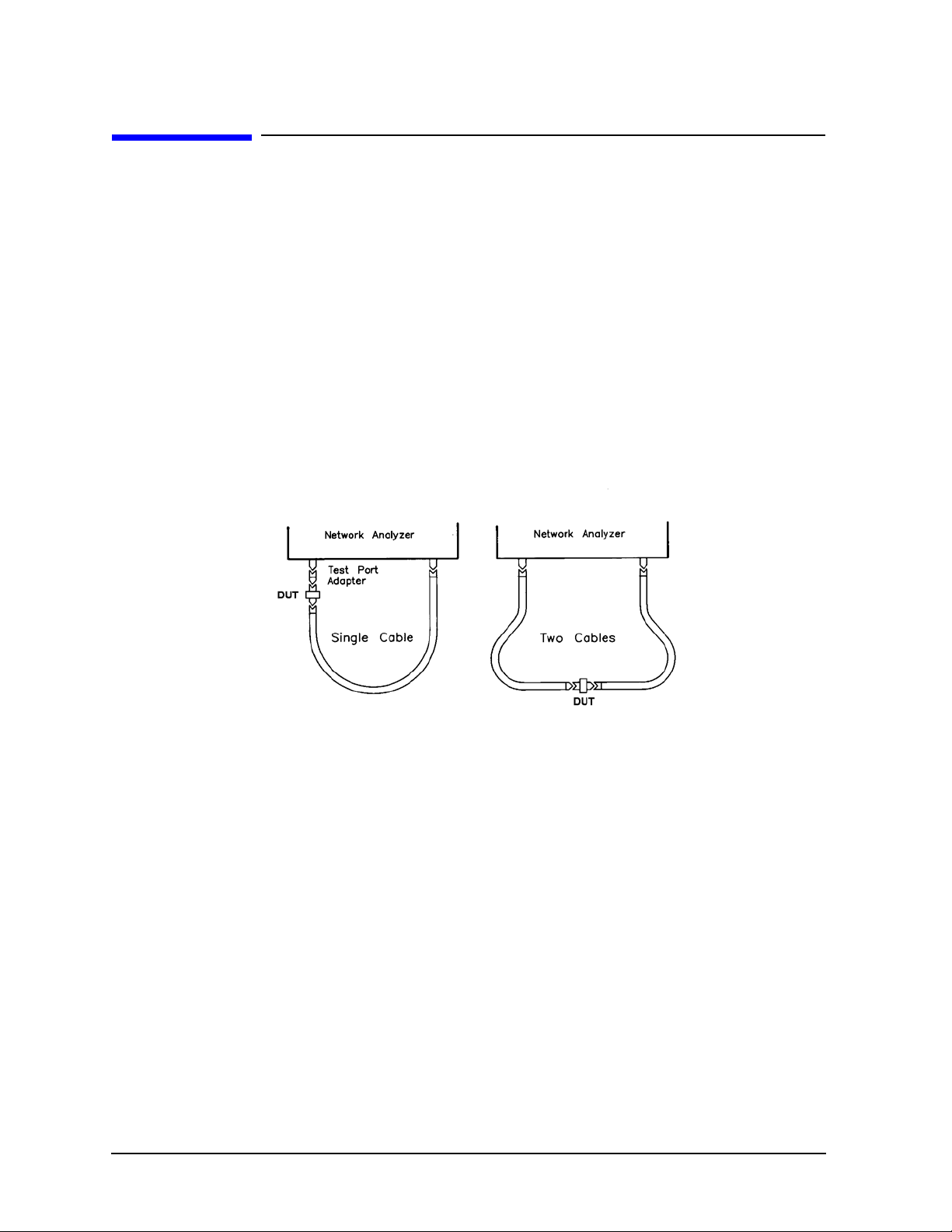
The 85133E set contains a single cable. Use it when a DUT is connected, with the
appropriate adapter, directly to the test set test port. See Figure 1-1.
85133F
The 85133F set contains two cables. Each is shorter than the 85133E cabl e. Use the
85133F cables when a DUT is connected between cable ends. See Figure 1-1.
Figure 1-1 Cable Configurations
85133H
The 85133H set contains a single cable – the -f- to -m- cable from the 85133F cable set. It is
shorter than the 85133E single cable. See Figure 1-1.
Connector Designators
NMD Connectors
NMD denotes a connector that has larger than standard coupling threads for greater
stability. NMD connectors are used on test cables, test ports, test port adapters, and test
port cables.
Female slotted NMD test port connectors are used on the test set end of adapters and
cables, and cannot be connected to standard male connectors.
Male NMD connectors are used on tes t sets (as test p orts), and on the DUT end of adapters
and cables. Male connectors have both the larger threads (for use with test port adapters)
and standard threads (for direct coupling to a DUT).
1-2 85133E/F/H
Page 9

General Information
Incoming Inspection
PSC Connectors
PSC denotes a precision slotless connector. Precision slotless connectors are metrology
grade connectors that have better electrical performance, better repeatability, and are
more durable than slotted connectors.
Clarifying the Terminology of a Connector Interface
In this document and in the prompts of the PNA calibration wizard, the gender of cable
connectors and adapters is referred to in terms of the center conductor. For example, a
connector or device designated as 1.85 mm –f– has a 1.85 mm female center conductor.
8510-series , 872 x , a nd 87 5x ON LY: In contrast, during a measurement calibration, the
network analyzer softkey menus label a 1.85 mm calibration device with reference to the
sex of the analyzer’s test port connector—not the calibration device connector. For
example, the label SHORT(F) refers to the short that is to be connected to the fem a le test
port. This will be a male short from the calibration kit.
Table 1-1 Clarifying the Sex of Connectors: Examples
Terminology Meaning
Short
–f–
Short (f) Male short (male center conductor) to be connected to female port
A connector gage is referred to in terms of the connector that it measures. For instance, a
male connector gage has a female connector on the gage so that it can measure male
devices.
Female short (female center conductor)
Incoming Inspection
Verify that the shipment is complete by referring to Table 4-1 on page 4-4.
If the case or any device appears damaged, or i f the shipment is incompl ete, not ify Agilent.
See “Contacting Agilent” on page 4-3. Agilent will arrange for repair or replacement of
incomplete or damaged shipments without waiting for a settlement from the
transportation company.
When you send the cable set to Agilent, include the following information:
• your company name and address
• the name of a technical contact person within your company, and the person’s complete
phone number
• the model number and serial number of the cable set
85133E/F/H 1-3
Page 10

General Information
Preventive Maintenance
• the part number and serial number of the device
• the type of ser v i ce re q u i red
•a detailed description of the problem
Preventive Maintenance
The best techniques for maintaining the integrity of the cables include:
• routine visual inspection
• cleaning
• proper gaging
• proper connection techniques
• proper storage
All of the above are described in Chapter 3. Failure to detect and remove dirt or metallic
particles on a mating plane surface can degrade repeatability and accuracy and can
damage any connector mated to it. Improper connections, resulting from center conductor
values being out of limits (see Table 2 on page 2-4), or from bad connections, can also
damage cable connectors.
Replaceable Parts
See Table 4-1 on page 4-4 for a complete list of cable set contents and their associated part
numbers (you can order a single cable rather than the entire cable set), and for
recommended items not included with the cable set. Refer to “Contacting Agilent” on
page 4-3 for information about communicating with Agilent.
1-4 85133E/F/H
Page 11

2 Specifications
85133E/F/H 2-1
Page 12

Specifications
Environmental Requirements
Environmental Requirements
Table 2-1 Environmental Requirements
Parameter Limits
Operating temperature +20 °C to +26 °C (+68 °F to +79 °F)
Storage temperature −40 °C to +75 °C (−40 °F to +167 °F)
Altitude
Operation < 4,500 meters (≈15,000 feet)
Storage < 4,500 mete rs (≈15,000 feet)
Relative humidity Always non-condensing
Operation Up to 80% at 30°C
Storage Up to 95% at 40°C
Electrical Specifications
Table 2-2 Electrical Specifications
Cable SWR Return Loss
(dB)
85133E ≤1.44 ≥15 ≤0.1 + 0.57√f
85133F ≤0.1 + 0.38√f
85133H
a. f = frequency in GHz.
Insertion
Loss (dB)
+ 0.02f
+ 0.017f
Frequency Range
a
(GHz)
DC to 50
2-2 85133E/F/H
Page 13
Specifications
Supplemental Characteristics
Supplemental Characteristics
T able 2-3 lists supp lementa l perfor mance char acte ristic s. These are not specifi cati ons, but
are intended to provide additional information useful to your application. Supplemental
characteristics are typical (but not warranted) performance parameters.
Table 2-3 Supplemental Characteristics (1 of 3)
Cable Cable Length Approximate
Electrical Length
cm in m ft cm in
85133E 97.2 38.25 1.125 3.690 <0.15 dB Change
85133F 62.9 24.75 0.7376 2.418 <0.08 dB Change
85133H
a. (f) = frequency in GHz.
b. With a 90°, 2.5-inch bend radius.
c. After three 90°, 2.5-inch bend radius/straighten cycles.
Magnitude and
Phase Stability
With a 90°
a,b
Bend
<0.17° (f) + 0.5°
<0.08° (f) + 0.5°
Random Use
Magnitude and
Phase Stability
<0.07 dB Change
<0.09° (f) + 0.5°
<0.04 dB Change
<0.04° (f) + 0.5°
Table 2-3 Supplemental Characteristics (2 of 3)
Cable Set N umber
of Cables
85133E 1 NMD-2.4 mm -f- Slotted PSC-2.4 mm -f- Slotless
Test Set End Connector Typ e DUT End Connector Type
Minimum
Recommended
a,c
Bend Radius
6.352 2.5
85133F 2 NMD-2.4 mm -f- Slotted NMD-2.4 mm -m- and
PSC-2.4 mm -f- Slotless
85133H 1 NMD-2.4 mm -f- Slotted NMD-2.4 mm -m-
Center Conductor Pin Depth
Center conductor pin depth is the distance the center conductor mating plane differs from
being flush with the outer conductor mating plane. See Figure 2-1 The pin depth of a
center conductor can be in one of two states: either protruding or recessed.
Protrusion is the condition in which the center conductor extends beyond the outer
conductor mating plane. This c ondition will indi cate a pos itive value on the c onnector gage.
Recession is the condition in which the center conductor is set back from the outer
conductor mating plane. This condition will indi cate a negative value on the connector
gage.
85133E/F/H 2-3
Page 14

Specifications
Supplemental Characteristics
Figure 2-1 Connector Center-Conductor Pin Depth
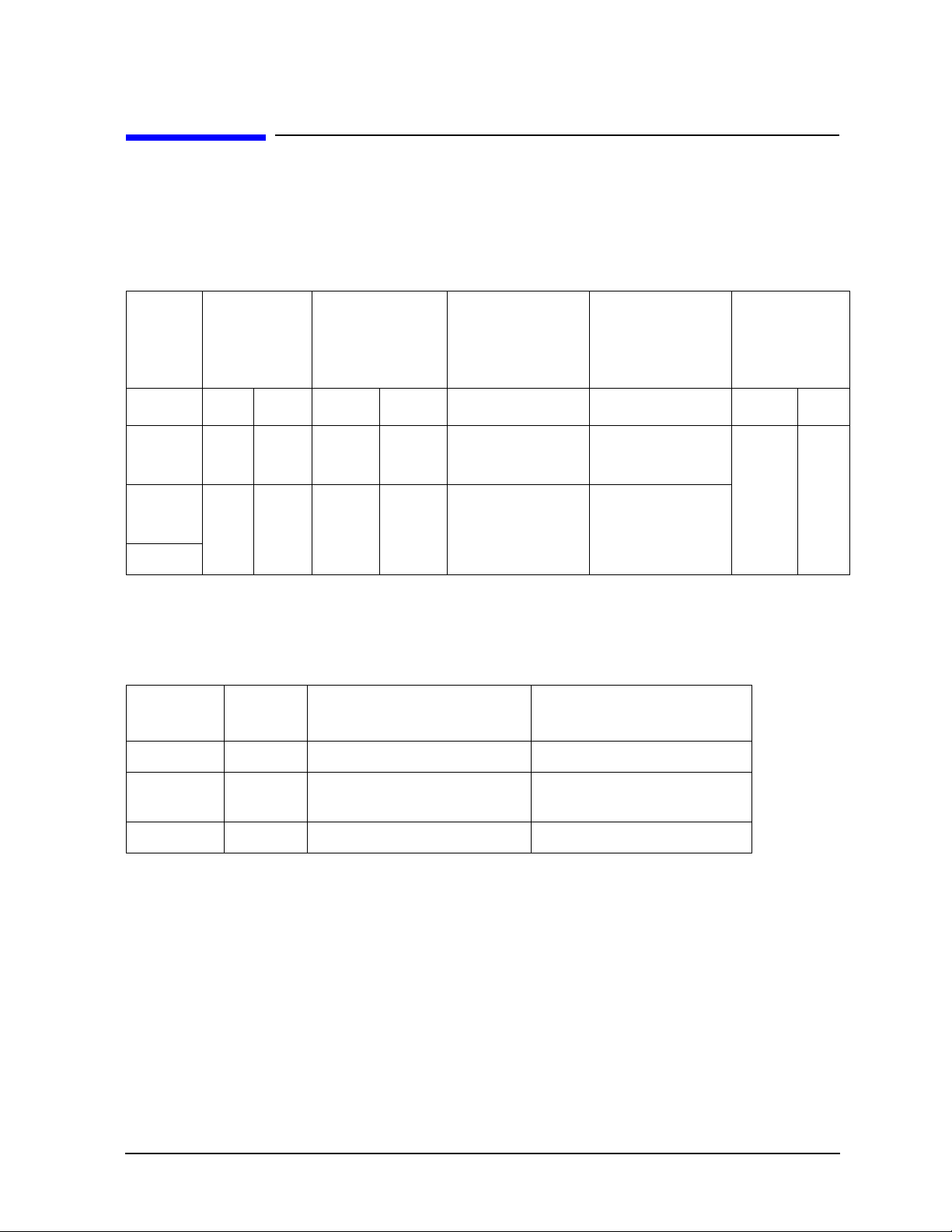
Table 2-3 Supplemental Characteristics (3 of 3)
Center-Conductor Pin Depth
Precision
Allowable Recession
a
Connector
mm in mm in
NMD-2.4 mm -f- -0.000 to -0.056 -0.0000 to -0.0022 0.0000 0.0000
NMD-2.4 mm -m- -0.0025 to -0.0254 -0.0001 to -0.001
PSC-2.4 mm -f- -0.0025 to -0.0254 -0.0001 to -0.001
a. Center conductor shoulder behind outer conductor mating plane.
Allowable Protrusion
2-4 85133E/F/H
Page 15

3 Use, Maintenance, and Care of the
Cables
85133E/F/H 3-1
Page 16

Use, Maintenance, and Care of the Cables
Electrostatic Discharge
Electrostatic Discharge
Protection against ESD (electrostatic discharge) is essential while connecting, inspecting,
or cleaning connectors attached to a static -sensitive circuit (such as those found in test
sets).
Static electricity can build up on your body and can easily damage sensitive internal
circuit elements when discharged. Static disc harges too small to be felt can cause
permanent damage. Devices such as calibration components and devices under test
(DUTs), can also carry an ele ct rostatic charge. To pre v e n t da mage to the test se t,
componen ts, and device s:
• always wear a grounded wrist strap having a 1 MΩ resistor in series with it when
handling components and devices or when making connections to the test set.
• always use a grounded, conductive table mat while making connections.
• always wear a heel strap when working in an area with a conductive floor. If you are
uncertain about the conductivity of your floor, wear a heel strap.
• always ground yourself before you clean, inspect, or make a connection to a
static-sensitive device or t est p ort. You ca n, for example , grasp t he ground ed oute r s hell
of the test port or cable connector briefly.
• always ground the center conductor of a test cable before making a connection to the
analyzer test port or other static-sensitive device. This can be done as follows:
1. Connect a short (from your calibration kit) to one end of the cable to short the cent er
conducto r to th e ou ter conduct o r.
2. While wearing a grounded wrist strap, grasp the outer shell of the cable connector.
3. Connect the other end of the cable to the test port.
4. Remove the short from the cable.
Refer to Chapter 4 for part numbers and instructions for ordering ESD protection devices.
Figure 3-1. ESD Protection Setup
3-2 85133E/F/H
Page 17

Use, Maintenance, and Care of the Cables
Visual Inspection
Visual Inspection
Visual inspection and, if necessary, cleaning should be done every time a connection is
made. Metal particles fro m the connector th reads may fall onto the mating plane surf ace of
the connect o r w h e n it is di sconnected. One connect i on ma de with a dirty or damaged
connector can damage both connectors beyond re pair.
Magnification is helpful when inspecting connectors, but it is not required and may
actually be misleading. Defects and damage that cannot be seen without magnification
generally have no effect on electrical or mechanical performance. Magnification is of great
use in analyzing the nature and cause of the damage and in cleaning connectors, but it is
not required for inspect ion. Use t he follo wing guidel ines when evaluating t he integrity of a
connector.
Look for Obvious Defects and Damage First
Examine the connector first for obvious defects and damage: badly worn plating on the
connector interface, deformed threads, or bent, broken, or misaligned center conductors.
Connector nuts should move smoothly and be free of burrs, loose metal particles, and
rough spots.
What Causes Connector Wear?
Connector wear is caused by connecting and disconnecting the cable . The more use a
connector gets, the faster it wears and degrades. The wear is greatly accelerated when
connectors are not kept clean, or are connected incorrectly.
Connector wear eventually degrades performance of the cable. Replace cables with worn
connectors.
The test port connectors on the network analyzer test se t may have many connections each
day, and are therefore also subject t o wear. It is recommended that an adapter be used a s a
test port saver to minimize the wear on the test s e t’s test port connectors.
Inspect the Mating Plane Surfaces
Flat contact between the connectors at all points on their mating pl ane surfaces is required
for a good connection. Look especially for deep scratches or dents, and for dirt and metal
particles on the connector mating plane surfaces. Also look for signs of damage due to
excessive or uneven wear or misalignment.
Light burnishing of the mating plane surfaces is normal, and is evident as light scratches
or shallow circular marks distributed more or less uniformly over the mating plane
surface. Other small defects and cosmetic imperfections are also normal. None of these
affect electrical or mechanical per formance.
If a connector shows deep scratches or dents, particles clinging to the mating plane
surfaces, or uneven wear, clean and inspect it again. Cables with damaged connectors
should be repaired or discarded. Determine the cause of damage before connecting a new,
undamaged connector in the same configuration.
85133E/F/H 3-3
Page 18

Use, Maintenance, and Care of the Cables
Precision Slotless Connectors (2.4 mm)
Precision Slotless Connectors (2.4 mm)
The female 2.4 mm connectors in the cable sets are metrology-grade, precision slotless
connectors (PSC). Precision slot less connectors are used to improve accuracy. A
characteristic of metrology-grade connectors is directly traceability to national
measurement standards through the ir we ll-def ined mechanic al d imensions . With PSCs on
test ports and standards, the accuracy achieved when measuring at 50 dB return loss
levels is comparable to using conventional slotted connectors measuring devices having
only 30 dB return loss. This represents an accuracy improvement of about 10 times.
Conventional female center conducto rs are slott ed and, whe n mated, are fl ared by the male
pin. Because physical dimensions determine connector impeda nce, this change in physical
dimension affects electrical performance, making it very difficult to perform precision
measurements with conventional slotted connectors .
The precision slotless connector was developed to eliminate this problem. The PSC has a
center conductor with a solid cylindrical shell, the outside diameter of which does not
change when mated. Instead, the center conductor has an internal con tact that flexes to
accept the male pin.
3-4 85133E/F/H
Page 19

Use, Maintenance, and Care of the Cables
Cleaning Connectors
Cleaning Connectors
Clean connectors are essential for ensuring the integrity of RF and microwave coaxial
connections.
1. Use Compressed Air or Nitrogen
WARNING
Use compressed air (or nitrogen) to loosen particles on the connector mating plane
surfaces.
You can use any source of clean, dry, low-pressure compressed air or nitrogen that has
an effective oil-vapor filter and liquid cond ensation trap placed just before the outlet
hose.
Ground the hose nozzle to prevent electrostatic discharge, and set the air pressure to
less than 414 kPa (60 psi) to control the velocity of the air stream. High-velocity
streams of compressed air can caus e electrostatic effects when di rected into a connecto r.
These electrostatic effects can damage the device. Refer to “Electrostatic Discharge”
earlier in this chapter for additional information.
2. Clean the Connector Threads
WARNING
Use isopropyl alcohol with adequate ventilation and avoid contact with eyes,
skin, and clothing. It causes skin irritation, may cause eye damage, and is
harmful if swallowed or inhaled. It may be harmful if absor bed through the s kin.
Wash thoroughly after handling.
Always use protective eyewear when using compressed air or
nitrogen.
Keep isopropyl alcohol away from heat, sparks, and flame. Store in a
tightly closed container . It is extremely flammable. In case of fire, use
alcohol foam, dry chemical, or carbon dioxide; water may be
ineffective.
In case of spill, soak up with sand or earth. Flush spill area with water.
Dispose of isopropyl alcohol in accordance with all applicable federal,
state, and local environmental regulations.
Use a lint-free swab or cleaning cloth moistened with isopropyl alcohol to remove any
dirt or stubborn contaminants on a connector that cannot be removed with compressed
air or nitrogen. Refer to T able 4 -1 on page 4-4 for part numbers for isopropyl alcohol and
cleaning swabs.
a. Apply a small amount of isopropyl alcohol to a lint-free cleaning swab.
b. Clean the connector threads.
c. Let the alcohol evaporate, then blow the threads dry with a gentle stream of clean,
low-pressure compresse d air or nitroge n . A lways comple te l y dr y a co n n e ctor before
85133E/F/H 3-5
Page 20

Use, Maintenance, and Care of the Cables
Cleaning Connectors
you reassemble or use it.
3. Clean the Mating Plane Surfaces
a. Apply a small amount of isopropyl alcohol to a lint-free cleaning swab.
b. Clean the center and outer conductor mating plane surfaces. Refer to Figure 2-1 on
page 2-4. When cleaning a female connector, avoid snagging the swab on the center
conductor contact fingers by using short strokes.
c. Let the alcohol evaporate, t hen bl ow the co nnect or dry wit h a gentle stream o f clean,
low-pressure compresse d air or nitroge n . A lways comple te l y dr y a co n n e ctor before
you reassemble or use it.
4. Reinspect
Inspect the connector again to make sure that no particles or resi due are present.
3-6 85133E/F/H
Page 21

Use, Maintenance, and Care of the Cables
Gaging Connectors
Gaging Connectors
The gages available from Agilent Technologies are intended for preventive maintenance
and troubleshooting purposes only. (See T able 4-1 on page 4-4 for part number
information.) They are effective in detecting excessive center conductor protrusion or
recession, and conductor damage on test cables and other accessories, DUTs, and
calibration kit devices. Do not use the gages for precise pin depth measurements.
Connector Gage Accuracy
The connector gages are only capable of performing coarse measurements. They do not
provide the degree of accuracy necessary to pr ecisely measure the pin depth of the cable
connectors. This is partially due to the repeatabil ity uncertain ties that are assoc iated with
the measurement. Only the factory—through special gaging processes and electrical
testing— can accurately verify the mechanical characteris tics of the cable connectors.
With prope r technique, however , the gages are us eful in detecting gross pin depth errors on
cable connectors. To achieve maximum accuracy, random errors must be re duced by taking
the average of at least three measurements having different gage orientations on the
connector. Even the resultant average can be in error by as much as ± 0.0001 inch due to
systematic (biasing) errors usually resulting from worn gages and gage masters. The
information in Table 2-3 on page 2-4 assumes new gages and gage masters. As your gages
undergo more use, their systematic errors can become more significant in the accuracy of
the measurement.
NOTE
When measuring pin depth, the measured value (resultant average of three
or more measurements) contains measurement uncertainty and is not
necessarily the true value. Always compare the measured value with the
observed pin depth limits (which account for measurement uncertainties) in
Table 2 on page 2-4 to evaluate the condition of cable connectors.
When to Gage Connectors
Gage a connector at the following times:
• Prior to using a cable fo r the firs t time: record the pin dep th measureme nt so that i t can
be compared with future read ings. (It will s erve as a good t roubleshooting too l when you
suspect damage may have occurred to the cable connector.)
• If either visual inspection or electrical performance suggests that the connector
interface may be out of typical range (due to wear or damage, for example).
• If a cable is used by someone else or on another system or piece of equipment.
• Initially after every 100 connections, and after that as often as experience indicates.
85133E/F/H 3-7
Page 22

Use, Maintenance, and Care of the Cables
Gaging Connectors
Gaging Procedures
Gaging 2.4 mm Connectors
NOTE
Always hold a connector gage by the gage barrel, below the dial indicator.
This gives the best stability, and improves measurement accuracy. (Cradling
the gage in your hand or holding it by the dial applies stress to the gage
plunger mechanism through the dial indicator housing.)
1. Select th e p r oper gage for yo u r connector. Refer to Table 4-1 on page 4-4 for gage part
numbers.
2. Inspect and clean the gage, gage master, and device to be gaged. Refer to “Visual
Inspection” and “Cleaning Connectors” earlier in this chapter.
3. Zero the connector gage (refer to Figure 3-2):
a. While holding the gage by the barrel, and witho ut turning the gage or the device,
connect the gage to the gage master by interconnecting the male and female
connectors. Connect the nut finger tight. Do not overtighten.
b. Using an open-end wrench to keep the device body from rotating, use the torq ue
wrench recommended for use to tighten the connecting nut to the specified torque.
Refer to “Final Connection Using a Torque Wre nch” on page 3-10 for additional
information.
c. As you watch the gage pointer, gently tap the barrel of the gage to settle the reading.
The gage pointer should line up exactly with the zero mark on the gage. If not, adjust
the zero set knob until the gage pointer lines up exactly with the zero mark.
d. Remove the gage master.
4. Gage the device connector (refer to Figure 3-2):
a. While holding the gage by the barrel, and witho ut turning the gage or the device,
connect the gage to the device by interconnecting the male and female connectors.
Connect the nut finger-tight. Do not overtighten.
b. Using an open-end wrench to keep the device body from rotating, use the torq ue
wrench included in the kit to tighten the connecting nut to the specified torque.
Refer to “Final Connection Using a Torque Wre nch” on page 3-10 for additional
information.
c. Gently tap the barrel of the gage with your finger to settle the gage reading.
d. Read the gage indicator dial. Read only the black ± signs; not the red ± signs.
For maximum accuracy, measure the connector a minimum of three times and take
an average of the readings. After each measurement, rotate the gage a quarter-turn
to reduce measurement variations that result from the gage or t he connector face no t
being exactly perpendicular to the center axis.
e. Compare the average reading with the observed pin depth limits in Table 2-3 on page
2-4.
3-8 85133E/F/H
Page 23
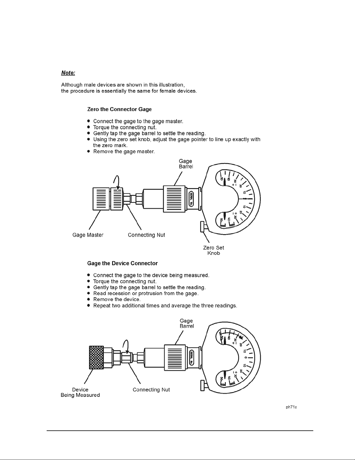
Figure 3-2 Gaging 2.4 mm Connectors
Use, Maintenance, and Care of the Cables
Gaging Connectors
85133E/F/H 3-9
Page 24

Use, Maintenance, and Care of the Cables
Making Connections
Making Connections
Good connections require a skilled operat or. The most common cause of meas ure men t erro r
is bad connections. The following procedures illustrate how to make good connections.
How to Make a Connection
Preliminary Connection
1. Ground yourself and all devices. Wear a grounded wrist strap and work on a grounded,
conductive table mat. Refer to “Electrostatic Discharge” on page 3-2 for ESD
precautions.
2. Visually ins pect the connectors. Refer to “Visual Inspectio n” on page 3-3.
3. If necessary, clean the connectors. Refer to “Cleaning Connectors” on page 3-5.
4. Use a connector gage to verify that all center conductors are within the observed pin
depth values in Table 2-3 on page 2-4. Refer to “Gaging Connectors” on page 3-7.
5. Carefully align the connectors. The male connector center pin must slip concentrically
into the contact finger of the female connector.
6. Push the connectors straight together and tight en the connector nut finger-tight.
CAUTION
Do not twist or screw the connectors together. As the center conductors mate, there is
usually a slight resistance.
7. The preliminary connection is tight enough when the mating plane surfaces make
uniform, light contact. Do not overtighten this connection.
A connection in which the outer conductors make gentle contact at all points on both
mating surfaces is sufficient. Very light finger pressure is enough to accomplis h this.
8. Make sure the connectors are properly supported. Relieve any side pressure on the
connection from long or heavy devices or cables.
Final Connection Using a Torque Wrench
Use a torque wrench to make a final connection. Table 3-1 provides information about the
torque wrench recommended for use with the calibration kit. Refer to Table 4-1 on page 4-4
for replacement part number and ordering information.
Table 3-1 Torque Wrench Information
Do not turn the device body. Only turn the connector nut. Damage to the
center conductor can oc c u r i f th e device body is twisted.
Connector Type Torque Setting Torque Tolerance
2.4 mm 90 N-cm (8 in-lb) ±9.0 N-cm (±0.8 in-lb)
3-10 85133E/F/H
Page 25

Use, Maintenance, and Care of the Cables
Making Connections
Using a torque wrench guarantees that t he co nnection is not too tight, preventi ng pos sible
connector damage. It also guarantees that all connections are equa lly tight each time.
Prevent the rotation of anything other than the connector nut that you are tightening. It
may be possible to do this by hand if one of the connectors is fixed (as on a test port).
However, it is recommended that you use an open-end wrench to keep the body of the
device from turning.
1. Position both wrenches within 90 degrees of each other before applying force. See
Figure 3-3. Wrenches opposing each other (greater than 90 degrees apart) will cause a
lifting action which can misalign and stress the connections of the devices involved.
This is especially true when several devices are connected together.
Figure 3-3 Wrench Positions
2. Hold the torque wrench lightly, at the end of the handle only (beyond the groove). See
Figure 3-4.
Figure 3-4 Using the Torque Wrench
3. Apply downward force perpendicular to the wrench handle. This applies torque to the
connection through the wrench.
Do not hold the wrench so tightly that you push the handle straight down along its
length rather than pivoting it, otherwise you apply an unknown amount of torque.
85133E/F/H 3-11
Page 26

Use, Maintenance, and Care of the Cables
Handling and Storage
4. Tighten the connection just to the torque wrench break point. The wrench handle gives
way at its internal pivot point. See Figure 3-4. Do not tighten the connection further.
CAUTION
You don’t have to fully break the handle of the torque wrench to reach the
specified torque; doing so can cause the handle to kick back and loosen the
connection. Any give at all in the handle is sufficient torque.
How to Separate a Connection
To avoid lateral (bending) force on the connec tor mating pla ne surfaces, always support the
devices and connections.
CAUTION
1. Use an open-end wrench to prevent the device body from turning.
2. Use the torque wrench to loosen the connecting nut.
3. Complete the separation by hand, turning only the connect ing nut.
4. Pull the connectors straight apart without twisting, rocking, or bending either of the
connectors.
Do not turn the device body. Only turn the connector nut. Damage to the
center conductor can oc c u r i f th e device body is twisted.
Handling and Storage
• Install the protective end caps and s tore the ca bles in the fo am-lined storage ca se when
not in use.
• Never store cables loose in a box, desk, or bench drawer. This is the most common cause
of cable connector damage during storage.
• Store cables in the same shape the y have when you use them; d o not eith er straighte n a
cable or flex it more tightly. Even flexible cables last longer if you flex them as little as
possible.
• Keep cable connectors clean.
• Do not touch connector mating plane surfaces. Natural skin oils and microscopic
particles of dirt are easily transferred to a connector interface and are very difficult to
remove.
• Do not set cable connectors contact-end down on a hard surface. The plating and the
mating plane surfaces can be damaged if the interface comes in contact with any hard
surface.
3-12 85133E/F/H
Page 27

Use, Maintenance, and Care of the Cables
Handling and Storage
Avoiding Cable Movement
When you use cables to m ake a precise calibration, you may have to fixture the cables to
prevent excessive movement after the calibration. In some cases, unless you res trict cable
movement, you may not be able to perform a verification after the calibration, especially if
you use a precision calibration kit.
NOTE
After you perform a calibration, move the cables as little as possible. Every
time you bend a cable, the phase changes slightly.
85133E/F/H 3-13
Page 28

Use, Maintenance, and Care of the Cables
Handling and Storage
3-14 85133E/F/H
Page 29

4 Replaceable Parts
85133E/F/H 4-1
Page 30

Replaceable Parts
Ordering Replaceable Parts
Ordering Replaceable Parts
Table 4-1 on page 4-4 lists the replacement part numbers for items included in the
85133E/F/H cable sets.
To order a listed part, note the description, the part number, and the quantity desired.
Telephone or send your order to Agilent Technologies (see “Contacting Agilent” on
page 4-3).
Ordering One Cable in a Cable Set
If you need only one of the cables in a cable set and don’t want to order an entire set, use
the appropriate single cable part number listed in Table 4-1 on page 4-4. When you order
using a single cable part number, you do not get a pair of cables; be sure you order the
correct cable part number(s).
4-2 85133E/F/H
Page 31

Replaceable Parts
Returning a Cable or Cable Set to Agilent
Returning a Cable or Cable Set to Agilent
If your cable set requires service, contact Agilent Technologies (see below). Include the
following information:
• your company name and address
• a technical contact person within your company, and the person's complete phone
number
• the model number and serial number of the cable set
• the part number and serial number of each device
• the type of ser v i ce re q u i red
•a detailed description of the problem and how the device was being used when the
problem occurred (such as calibration or measurement)
Contacting Agilent
Assistance with test and measurement needs and information on finding a local Agilent
office are available on the Web at:
http://www.agilent.com/find/assist
If you do not have access to the Internet, please contact your Agilent field engineer.
NOTE
In any correspondence or telephone conversation, ref er to the Agilent product
by its model number and full serial number. With this information, the
Agilent representative can determine whether your product is still within its
warranty period.
Information About Network Analyzers
This document contains limited information about network analyzer system operation. For
complete information, refer to the instrument documentation.
85133E/F/H 4-3
Page 32

Replaceable Parts
Returning a Cable or Cable Set to Agilent
Table 4-1 Replaceable Parts
Descriptiona
Cables
85133E Single Cable:
NMD-2.4 mm –f– to PSC-2.4 mm –f– 1 85133-60015
85133F Cables:
NMD-2.4 mm –f– to NMD-2.4 mm –m– 1 85133-60017
NMD-2.4 mm –f– to PSC-2.4 mm –f– 1 85133-60016
85133H Single Cable:
NMD-2.4 mm –f– to NMD-2.4 mm –m– 1 85133-60017
Miscellaneous
Operating and Service Manual 1 85133-90017
Protective End Caps
STR 0.812-ID black as
STR 0.234-ID red 1401-0202
Items NOT Included in a Cable Set:
Qty Agilent Part Number
1401-0214
necessary
ESD Protective Devices
Grounding wrist strap 1 9300-1367
5 ft grounding cord for wrist strap 1 9300-0980
2 ft by 4 ft conductive table mat with 15 ft grounding
wire
ESD heel strap 1 9300-1308
Connector Cleaning Supplies
Isopropyl alcohol 30 ml 8500-5344
Foam tipped cleaning swabs 100 9301-1243
Wrenches
20 mm (8 in–lb) torque wrench 1 8710-1764
5/16 in., 90 N–cm (8 in–lb) torque wrench 1 8710-1765
7 mm open-end wrench 1 8710-1761
Miscellaneous
2.4 mm female gage set 1 85056-60017
2.4 mm male gage set 1 85056-60018
1 9300-0797
10x Magnifying Glass 1 1000-1114
4-4 85133E/F/H
Page 33

Table 4-1 Replaceable Parts
Replaceable Parts
Returning a Cable or Cable Set to Agilent
Descriptiona
Qty Agilent Part Number
2.4 mm 50 Ω fixed termination -m- 1 00901-60001
2.4 mm 50 Ω fixed termination -f- 1 00901-60002
2.4 mm offset short -m- 1 85056-60001
2.4 mm offset short -f- 1 85056-60002
2.4 mm airline (5.0 cm) 1 85057-60001
a. Refer to “Clarifying the Terminology of a Connector Interface” on page 1-3.
85133E/F/H 4-5
Page 34

Replaceable Parts
Returning a Cable or Cable Set to Agilent
4-6 85133E/F/H
Page 35

A Connector Care Quick Reference
85133E/F/H A-1
Page 36

Connector Care Quick Reference
Principles of Microwave Connector Care
Principles of Microwave Connector Care
Proper connector care and connection techniques are critical for accurate, repeatable
measurements and for extending the life of your devices.
Prior to making connections to the network analyzer, carefully review the connector care
information provided with your product.
See the following table for quick reference tips about connector care.
A-2 85133E/F/H
Page 37
Connector Care Quick Reference
Principles of Microwave Connector Care
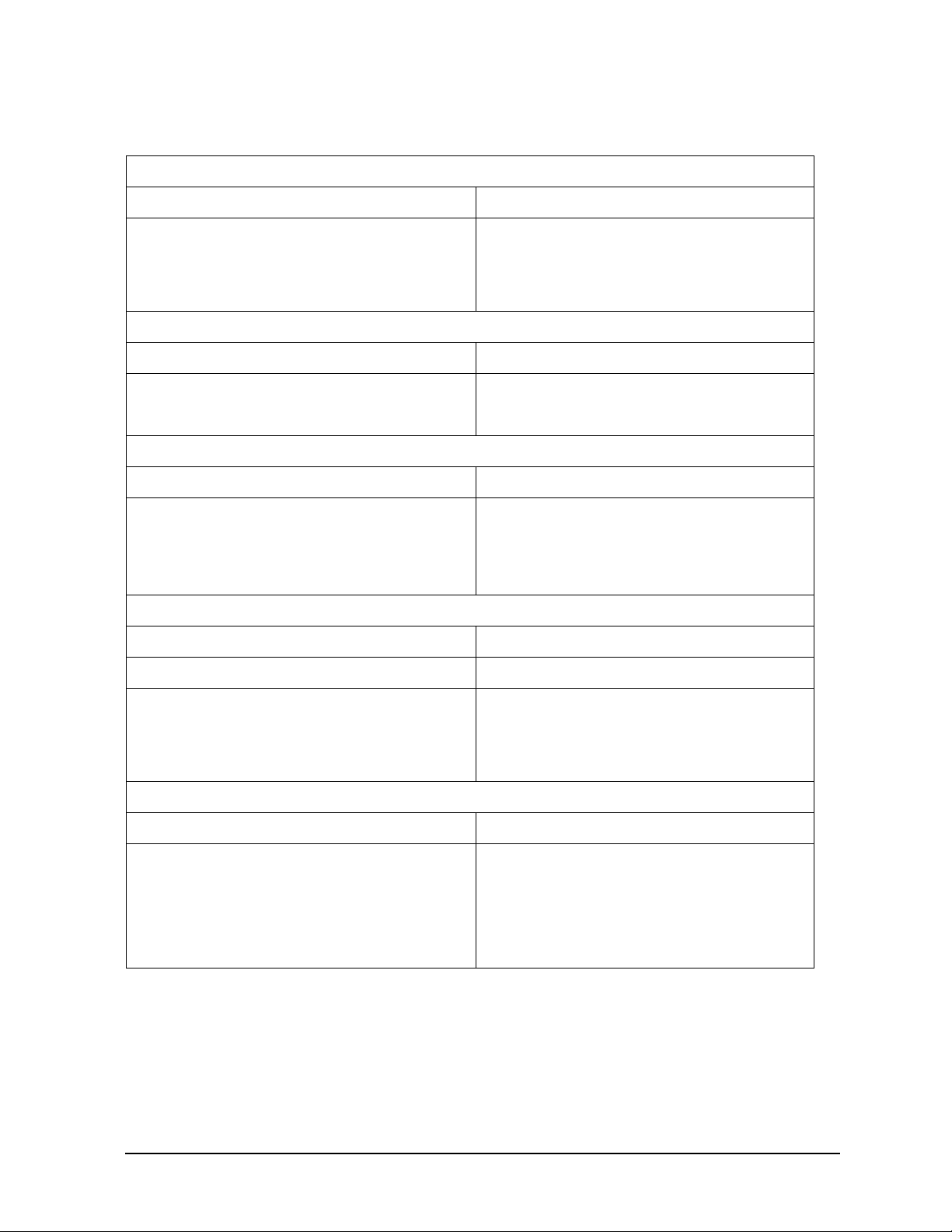
Table A-1 Connector Care Quick Reference
Handling and Storage
Do Do Not
Keep connectors clean Touch mating-plane surfaces
Extend sleeve or connector nut Set connectors contact — end down
Use plastic end-caps during storage
Visual Inspection
Do Do Not
Inspect all connectors carefully Use a damaged connector — ever
Look for metal particles, scratches, and dents
Connector Cleaning
Do Do Not
Tr y compressed air first Use any abrasives
Use isopropyl alcohol
a
Get liquid into plastic support beads
Clean connector threads
Gaging Connectors
Do Do Not
Clean and zero the gage before use Use an out-of-spec connector
Use the correct gage type
Use correct end of calibration block
Gage all connectors before first use
Making Connections
Do Do Not
Align connectors carefully Apply bending force to connection
Make preliminary connection lightly Over tighten preliminary connection
Turn only the connector nut Twist or screw any connection
Use a torque wrench for final connect Tighten past torque wrench “break” point
a. Use isopropyl alcohol in a well-ventilated area, allowing adequate time for moist
alcohol to evaporate and fumes to disperse prior to energizing equipment.
85133E/F/H A-3
Page 38

Connector Care Quick Reference
Principles of Microwave Connector Care
A-4 85133E/F/H
Page 39

Index
A
adapters, part numbers
Agilent,contacting, 4-3
alcohol, isopropyl, as cleaning solvent, 3-5
altitude, 2-2
avoiding cable movement, 3-13
C
cable
, 2-3
length
maintenance, 1-4
movement, 3-13
part numbers, 4-4
cable set
overview
return to Agilent, 4-3
center conductor pin depth, 2-3
characteristics
supplemental
cleaning connectors, 3-5
cleaning supplies
ordering, 4-4
part numbers, 4-4
communicating with Agilent, 4-3
compressed air or nitrogen, 3-5
conductor
mating plane
connections, 3-2, 3-10
ESD protection, 3-10
final, 3-10
preliminary, 3-10
separating, 3-12
using torque wrench, 3-10
connector
care, A-2
cleaning, 3-5
cleaning supplies, 4-4
damage, 3-3
gage
accuracy
handling, 3-8
when to do, 3-7
zeroing, 3-8
gaging, 3-8
life, 3-3
mating plane, 3-6
NMD type, 1-2
PSC type, 1-3
quick reference, A-3
sex, 1-3
slotless, 3-4
threads, 3-5
type
DUT end
test set end, 2-3
visual inspection, 3-3
wear, 3-3
connector terminology, 1-3
contacting Agilent, 4-3
, 1-2
, 2-3
, 2-3
, 3-7
, 2-3
, 4-4
D
damage
to connectors
to shipment, 1-3
defective connectors, 3-3
description of cable sets, 1-2
device
conductor
mating plane
connecting, 3-10
disconnecting, 3-12
handling, 3-12
part numbers, 4-4
return to Agilent, 4-3
storage, 3-12
visual inspecti on, 3-3
dimensions
device
outer conductor
disconnections, 3-12
documentation warranty, -ii
E
electrical length
electrical specifications, 2-2
electrostatic discharge, 3-2
supplies
part numbers
environmental requirements, 2-2
equipment
supplied, 4-2, 4-4
ESD, 3-2
precautions, 3-2, 3-5
supplies
part numbers
F
frequency range
specifications
G
gage
connector
handling
master, 4-4
zeroing, 3-8
gage master
part numbers
gaging
connectors
when to do, 3-7
gender, connector, 1-3
H
handling
humidity, 2-2
, 3-3
, 2-3
, 2-3
, 2-3
, 4-4
, 4-4
, 2-2
, 3-8
, 4-4
, 3-8
, 3-12
85133E/F/H
Index-1
Page 40

Index
I
incoming inspection
insertion loss
specificatons
inspection
damage
defects, 3-3
incoming, 1-3
mating plane, 3-3
visual, 3-3
isopropyl alcohol, as cleaning solvent, 3-5
L
length
cable
electrical, 2-3
M
magnitude
maintenance, 3-2
preventive, 1-4
making connections, 3-10
ESD protection, 3-10
precautions, 3-10
manual
part number, 4-4
mating plane
conductor, 2-3
connector, 3-6
inspection, 3-3
surfaces, 3-6
movement of cables, 3-13
N
nitrogen
NMD connectors, 1-2
O
open-end wrench
part number, 4-4
ordering parts, 4-2
P
parts
numbers
ordering, 4-2
replaceable, 4-2
required but not supplied, 4-4
phase stability, 2-3
pin depth, 2-3
definition of, 2-3
protrusion, 2-3
recession, 2-3
preventive maintenance, 1-4
protrusion
pin depth, 2-3
PSC connectors, 1-3
, 3-3
, 2-3
, 2-3
, 3-5
, 4-2
, 1-3
, 2-2
, 3-12
Q
quick reference, connector care
R
reaching Agilent
recession
pin depth
regulations
environmental
replaceable parts, 4-2
requirements
environmental, 2-2
return loss
specifications, 2-2
return, set or cable, 4-3
S
separating connections
set
overview
return to Agilent, 4-3
sex, connector, 1-3
shipment
damage
verifying complete, 1-3
specifications, 2-2
altitude, 2-2
electrical, 2-2
environmental, 2-2
frequency, 2-2
frequency range, 2-2
humidity, 2-2
insertion loss, 2-2
return loss, 2-2
temperature, 2-2
torque wrench, 3-10
stability, phase, 2-3
static discharge, 3-2
storage, 3-12
altitude, 2-2
humidity, 2-2
temperature, 2-2
supplemental characteristics, 2-3
T
temperature
operating range
threads
connector
torque wrench
part number
specifications, 3-10
V
visual inspection, 3-3
W
warranty, documentation, -ii
wrench
, 1-3
, 4-3
, 2-3
, 3-6
, 3-12
, 1-2
, 2-2
, 3-5
, 4-4
, A-3
Index-2
85133E/F/H
Page 41

Index
open-end
part numbers, 4-4
proper positioning of, 3-11
torque, 3-10, 3-11, 4-4
precautions for use of, 3-11
proper use of, 3-11
Z
zeroing
connector gage
, 3-11, 3-12, 4-4
, 3-8
85133E/F/H
Index-3
 Loading...