

Page 1

Operating and Service Manual
Agilent Technologies
85130F
NMD 2.4 mm to 3.5 mm
Adapter Kit
Part Number 85130-90030
Printed in USA
May 1988
© Copyright 1988 Agilent Technologies
Page 2

WARRANTY
This Hewlett-Packard instrument product is warranted against defects in material and workmanship
for a period of one year from date of delivery. During the warranty period, Hewlett-Packard Company
will, at its option, either repair or replace products which prove to be defective.
For warranty service or repair, this product must be returned to a service facility designated by HP.
Buyer shall prepay shipping charges to HP and HP shall pay shipping charges to return the product to
Buyer. However, Buyer shall pay all shipping charges, duties, and taxes for products returned to HP
from another country.
HP warrants that its software and firmware designated by HP for use with an instrument will execute
its programming instructions when properly installed on that instrument. HP does not warrant that the
operation of the instrument, or software, or firmware will be uninterrupted or error free.
LIMITATION OF WARRANTY
The foregoing warranty shall not apply to defects resulting from improper handling by Buyer,
Buyer-
supplied software or interfacing, unauthorized modification or misuse, or operation outside of the
environmental specifications for the product.
NO OTHER WARRANTY IS EXPRESSED OR IMPLIED, HP SPECIFICALLY DISCLAIMS THE
IMPLIED WARRANTIES OR MERCHANTABILITY AND FITNESS FOR A PARTICULAR PURPOSE.
EXCLUSIVE REMEDIES
THE REMEDIES PROVIDED HEREIN ARE BUYER’S SOLE AND EXCLUSIVE REMEDIES, HP SHALL
NOT BE LIABLE FOR ANY DIRECT, INDIRECT, SPECIAL, INCIDENTAL, OR CONSEQUENTIAL
DAMAGES, WHETHER BASED ON CONTRACT, TORT, OR ANY OTHER LEGAL THEORY.
ASSISTANCE
Product maintenance agreements and other customer assistance agreements are available for Hewlett-
Packard Products.
For any assistance, contact your nearest Hewlett-Packard Sales and Service
provided at the back of this manual.
Office.
Addresses are
,
Page 3

Notice
Hewlett-Packard to Agilent Technologies Transition
This documentation supports a product that previously shipped under the HewlettPackard company brand name. The brand name has now been changed to Agilent
Technologies. The two products are functionally identical, only our name has changed. The
document still includes references to Hewlett-Packard products, some of which have been
transitioned to Agilent Technologies.
Printed in USA March 2000
Page 4

Page 5

HP 85130F Adapter Kit
To obtain optimum performance from this adapter kit, observe these simple precautions:
l
Make connections carefully to avoid misalignment and connector damage, which will result in
inaccurate measurements.
l
Keep the connectors free of dirt and any particles.
l
When you clean the connectors, try compressed air first. Do not use abrasives. With a clean foam
swab, apply
l
For more information, refer to the Microwave Connector Care manual.
The HP 85130F adapter kit consists of two NMD-2.4 mm to 3.5 mm adapters and a spanner wrench.
The test set end of the adapters has a NMD-2.4 mm connector while the Device Under Test (DUT) end
has a precision connector. The NMD-2.4 mm to NMD-3.5 mm (m) adapter is used when a male test
port is required. The NMD-3.5 mm to PSC-3.5
female test port is required.
only
Freon TF as a solvent.
(9
(precision slotless connector) adapter is used when a
The HP 85130F kit contains the following:
Description
Test port adapters
NMD-2.4 mm to NMD-3.5 mm (m)
NMD-2.4 mm to PSC-3.5 (f)
Storage box, foam lined
d
.
4
.
HP 85130F
Operating and Service Manual
Spanner wrench
Quantity
Replacement
Part Number
85130-60010
85130-60011
85130-60013
85130-90030
08513-20014
NMD-2.4 mm to 3.5 mm Adapter Kit
1
Page 6

SPECIFICATIONS
Hewlett-Packard guarantees that
No
center conductor shoulder (male pin end of female center pin) protrusion is allowable
NMD-2.4 mm
Female
--Gp+
OUTER
CONDUCTOR
CENTER
CONDUCTOR
/
I I
I I
I
OUTER CONDUCTOR
MATING
‘I”-
PIANE
your adapters will equal or exceed the following specifications:
Table 1. HP
CENTER CONDUCTOR PROTRUSION
CENTER CONDUCTOR RECESSION
OUTER
CONDUCTOR
8513OF
Specifications
on any connector.
PSC-3.5
Female
+ypp
II
L
OUTER CONDUCTOR
MATING
I
PLANE
NMD-3.5 mm
Male
+
11
I
!,
OUTER CONDUCTOR
MATING PLANE
I
OUTER
CONDUCTOR
CENTER
CONDUCTOR
MP = male contact pin shoulder recession behind the outer conductor mating plane.
FP
=recession
Connector
of the end of female center pin behind the outer conductor mating plane.
Allowable Recession
mm in
NMD-2.4 mm female +O.OOO to
PSC-3.5 female
+ 0.00254 to + 0.0127 +0.0001
+0.056
NMD-3.5 mm male + 0.00254 to + 0.0127
ELECTRICAL
Adapter Frequency Range
NMD-2.4 mm to PSC-3.5 female
and
NMD-2.4 mm to NMD-3.5 mm male
DC to 8
8Ghzto18GHz
18
GHz
GHz
to 26.5
+o.ooo to
to
+0.0001
to
Return Loss
232 dB
228 dB
~26 dB
+0.0022
+0.0005
+0.0005
2
NMD-2.4
mm to 3.5 mm Adapter Kit
HP 85130F
Page 7

Using an HP 8510 Network Analyzer perform the following test on your adapters as soon as you
receive them, and periodically repeat the test to determine if their performance meets the electrical
specifications stated above or if they need to be replaced. An initial period of one year between
performance tests is recommended.
Required Equipment
HP
851OB
Network Analyzer
with time domain option and
HP 8516A S-parameter Test Set
HP 834Xx Synthesized Sweeper
NOTE:
tion on instrument compatibility.
3.5
3.5 mm
Refer to the HP 8516A Operating and Service Manual for informa-
mm loads
(part of the HP 850528 calibration kit)
male . . . . . . . . . . . . . . . . . . . . . . . . . . . . . . . . . . . . . . . ...85052-60010
female . . . . . . . . . . . . . . . . . . . . . . . . . . . . . . . . . . . . . . .
5OQ
airline, 7.5 cm
(part of the HP 850538 verification kit)
TEST SET
. . . . . . . . . . . . . . . . . . . HP 8510 Option 010
B.04.OX
. . . . . . . . . . . . . . . . . . . . . . . . .
firmware or higher
PORT
ONE
I
m-
I
AIRLINE
HP Model/Part Number
.85052-60010
.85053-60005
50
LOAD
OHtl
4
,
I
Figure 1.
Return
adapter, then attaching the adapter to port one of the test set (see Figure 7).
The effects of an imperfect load may be gated out using the HP 8510 time domain option as follows:
1.
2.
3.
4.
HP
85l30F
loss is measured by connecting a 50.ohm fixed load termination through a 7.5 cm airline to the
Press
[PRESET].
Under STIMULUS, press
Under STIMULUS, press [STOP]
Perform a 2.4 mm one port sliding load
set, as described in the HP 8510 Operating and Programming manual. Save the calibration. Set up
as shown in Figure 1.
The HP 8510 will be set to a predetermined state.
[START]
[2]
1
.
mm
ADFlPTER
Return Loss Set-up
[4] [5] [M/p].
[6] [.] [5]
[G/n]. This sets the stop frequency to 26.5
Sll
calibration with 32 averaging at port one of your test
\ I 7
e-
This sets the start frequency to 45 MHz.
NMD-2.4 mm to 3.5 mm Adapter Kit
, I ,
--
GHz.
3
Page 8

5.
With correction turned on, under MENUS, press
and frequency functions to the softkeys. Select
mode.
[DOMAIN].
[TIME BANDPASS].
This brings up a set of time domain
This puts you in time domain
Under STIMULUS, press
6.
- .05
nanoseconds.
Under STIMULUS, press
7.
Under RESPONSE, press
8.
9.
Under the softkey functions, press
you to press
[STOP]
[START]
!,
[STOP]
[AUTO].
softkey.
[-I [.]
[0]
[l]
[G/n].
[5] [G/n].
This sets the stop time of the sweep to 1 nanosecond.
This sets the start time of the sweep to
This brings the trace on screen.
[SPECIFY GATE].
A new menu should appear that will allow
10. Using the RPG, adjust the stop gate to the center of the airline (see Figure 2).
11. Under the softkey functions press
[GATE ON].
The HP 8510 will now compute the gate coeffi-
cients to gate out everything but the adapter.
12.
Press the
that will allow
13.
Under MENUS, press
[MAXIMUM]
[PRIOR MENU]
you
to press the
[MARKER].
softkeys.
button just to the right of the softkeys and a new menu should appear
[FREQUENCY]
This brings up a set of functions to the softkeys. Select
softkey.
[MORE]
14. You can now read the return loss value from the screen marker value, and record the results on
the Performance Test Record provided.
StoD
Gate
*11
REF -5.0 mUnits
4.007
mUni ts/
LINEAR
.
/
Adapter End
of
Airline
Start
Gate
C
A
\
START -50.0
STOP
ps
1.0 ns
Figure 2. Location of Gates and Airline
Load End
of Airline
4 NMD-2.4 mm to 3.5 mm Adapter Kit
HP 85130F
Page 9
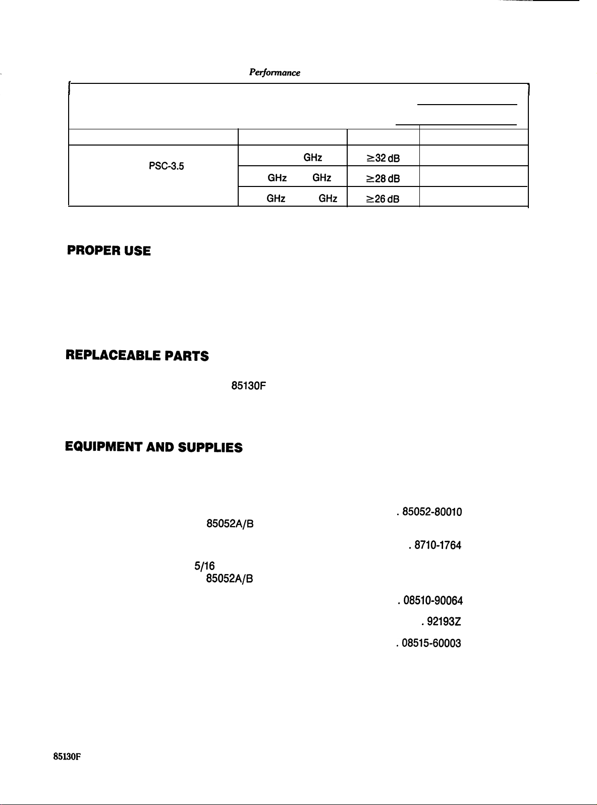
Pedomance
Test Record
I
ELECTRICAL SPECIFICATIONS
Adapter
NMD-2.4 mm to
and
NMD-2.4 mm to NMD-3.5 mm male
WC-35
female
Frequency Range
DC to 8 GHr
8
GHz
to 18
GHz
18
GHz
to 26.5
GHz
Tested by:
Date:
Return Loss
232 dB
228 dB
226 dB
Measured
1
Attach the adapters to the test ports and tighten them finger tight. Use the spanner wrench to hold the
test set end of the adapter and torque the test set connector with a 20 mm torque wrench set to 96 N-cm
(8 in-lb). Attach a non-rotating clamp to each test port.
There no replaceable parts in the HP
in whole.
8513OF
adapter kit. A worn or damaged adapter must be replaced
.
The following equipment and supplies are required for the maintenance and use of, but are not supplied
with, your HP 85130F adapter kit.
3.5 mm gage kit
(part of the HP
Torque wrench, 20 mm, 96 N-cm (8 in-lb) . . . . . . . . . . . . . . . .
Torque wrench,
. . . . . . . . . . . . . . . . . . . . . . . . . . . . . . . . . . .85052-80010
85052A/B
calibration kits)
.8710-1764
5/16
inch, 96 N-cm (8 in-lb) . . . . . . . . . . . . . . . 8710-1765
(part of the HP 85052A/B calibration kits)
Microwave Connector Care Manual
Connector cleaning kit
Non-rotating Clamp
. . . . . . . . . . . . . . . . . . . . . . . . . . . . . . . . .
. . . . . . . . . . . . . . . . . . . . . . . . . . . . . . . .08515-60003
. . . . . . . . . . . . . . . . . . .08510-90064
.92193Z
(two included with the HP 8516A test set)
HP
85l30F
NMD-2.4 mm to 3.5 mm Adapter Kit
5
 Loading...