

Page 1

Agilent Technologies 8511B
Frequency Converter Test Set
Operating and Service
Manual
Agilent Part Number: 08511-90073
Printed in USA November 2001
Supersedes Nove mber 1999
Page 2

Notice
The information containe d in this doc ument is subject to change without
notice.
Agilent Technologies makes no warranty of any kind with regard to this
material, including, but not limited to, the implied warranties of
merchantability and fitness fo r a particular purpose. Agilent shall not be
liable for error s cont ained herein or for incidenta l or consequential damages
in connection with the furni shing, performance, or use of this material.
Agilent assumes no re sponsibility for the us e or r eliability of its software on
equipment that is not furnished by Agilent.
This document contains proprietary information which is protected by
copyright. All rights are reserved. No part of this document may be
photocopied, reproduced, or translated to another langu age without prior
written consent of Agilent Technologies.
Hewlett-Packard to Agilent Technologies Transition
This documentation supports a product that previously shipped under the
Hewlett-Packard company brand name. The brand name has now been
changed to Agilent Te chnologies. The two products are functionally
identical, only our name has change d. The document still inc ludes references
to Hewlett-Packard products, some of which have been transitioned to
Agilent Technologies.
Restricted Rights Legend
Use, duplication, or disclosure by the U.S. Government is subject to
restrictions as set forth in subparagraph (c)(1)(ii) of the Rights in Technical
Data and Computer Software cla use at DFARS 252.227-7013 for DOD
agencies, and subparagr aphs (c)(1) and (c)(2) of the Commercial Computer
Software Restri cted Rights clause at FAR 52.227-19 for other agencies.
© Copyright Agilent Te chnologies, Inc. 1999, 2001
ii Agilent 8511B Test Set Operating and Service Manual
Page 3

What You’ll Find in This Manual…
Chapter 1 • General Information
Chapter 2 • Specifications
Chapter 3 • Installation
Chapter 4 • Operations
Chapter 5 • Performance Tests
Chapter 6 • Test Set Troubleshooting
Chapter 7 • Replacement Procedures
Chapter 8 • Replaceable Parts
Agilent 8511B Test Set Operating and Service Manual iii
Page 4

Warranty
Certification Agilent Technologies certifies that this product met its published
specifi cations at the time of shipment from the factory. Agilent further
certifi es that its calibration measurements are traceable to the United St ates
National Insti tute of Standards and Technology (NIST, formerly NBS), to the
extent allowed by the Institute’s calibration facility, and to the calibration
facilities of other I nternational Standards Organization members.
Warranty This Agilent system product is wa rranted against defects in materi als and
workmanship for a period corresponding to the individual warranty periods
of its component products. Instruments are warranted for a period of one
year. During the warranty peri od, Agilent will, at its option, either repair or
replace products that prove to be defective.
W arr anty se rvice for products in sta lled b y Agilent and certain other products
designated by Agile nt will be performed at Buyer’s facility at no charge
within Agilent servic e travel areas. Outside Agilent service travel areas,
warranty service will be per formed at Buyer’ s f acility only upon Agilent’s
prior agreement and Buyer shall pay Agilent’s round trip travel expense s. In
all other areas, products must be returned to a service facility designated by
Agilent.
For products returne d to Agilent for warranty serv ice, Bu y er sha ll pr epay
shipping charge s to Agilent and Agilent shall pay shipping char ges to return
the product to Buyer. However , Buyer shall pay all shippi ng charges, duties,
and taxes for products r eturned to Agilent from another country.
Agilent warr ants that its software and firmware designated by Agilent for
use with an instrument will e xecute its programming instructions when
properly install ed on that instrument. Agilent does not warrant tha t the
operation of the instrument, or software, or firmware will be uninterrupt ed or
error free.
LIMITATION OF WARRANTY. The foregoing warranty shall not apply
to defects resulti ng from improp er or inadequate maintenance by Buyer,
Buyer-supplied software or interfacing, unauthorized modification or
misuse, operation outside of the environmenta l spe cifications fo r the
product, or improper site prepa ration or maintenance.
NO OTHER WARRANTY IS EXPRESSED OR IMPLIED. AGILENT
SPECIFICALLY DISCLAIMS THE IMPLIED WARRANTIES OR
MERCHANTABILITY AND FITNESS FOR A PARTICULAR PURPOSE.
iv Agilent 8511B Test Set Operating and Service Manual
Page 5

EXCLUSIVE REMEDIES. THE REMEDIES PROVIDED HEREIN ARE
BUYER’S SOLE AND EXCLUSIVE REMEDIES. AGILENT SHALL
NOT BE LIABLE FOR ANY DIRECT, INDIRECT, SPECIAL,
INCIDENTAL, OR CONSEQUENTIAL DAMAGES, WHETHER BASED
ON CONTRACT, TORT, OR ANY OTHER LEGAL THEORY.
Assistance Product maintenance agre emen ts and other customer assistance agreements
are available for Agilent products.
For assistance , c al l your local Agilent Sales and Service Office (refer to
“Service and Support” on page vi).
Agilent 8511B Test Set Operating and Service Manual v
Page 6

Service and Support
Any adjustment, maintenance, or repair of this product must be performed
by qualif ied personnel. Contact your customer engine er through your local
Agilent Service Center. By internet, phone, or fax, get assistance with all
your test and measurement needs.
Online assistance: www.agilent.com/find/assist
United S t ates
(tel) 1 800 452 4844
New Zealand
(tel) 0 800 738 378
(fax) (+64) 4 495 8950
Malays ia
(tel) 1 800 828 848
(fax) 1 800 801 664
Taiwan
(tel) 0800-047-866
(fax) (886) 2 25456723
Latin America
(tel) (305) 269 7500
(fax) (305) 269 7599
Japan
(tel) (+81) 426 56 7832
(fax) (+ 81) 426 56 7840
Philippines
(tel) (632) 8426802
(tel) (
PLDT subscriber on ly):
1 800 16510170
(fax) (632) 8426809
(fax) (
PLDT subscriber o nly):
1 800 16510288
People’s Republic of China
(tel) (preferred): 800-810-0189
(tel) (alternate): 10800-650-0021
(fax) 10800-650-0121
vi Agilent 8511B Test Set Operating and Service Manual
Page 7

Safety and Regulato ry Informat ion
Review this product and related documentation to familiarize yourself with
safety markings and instr uct ions before you operate the instrument. This
product has been designed and teste d in acc ordance with international
standards.
WARNING The WARNING notice denotes a hazard. It calls attention to a proce dure,
practice, or the like, that, if not correctl y performed or adhered to, could result
in personal injury. Do not proceed beyond a WARNING notice until the
indicated conditions are fu lly understood and met.
CAUTION The CAUTION notic e denotes a hazard. It calls attention to an operating
procedure, practice, or the like, which, if not correctly performed or adhered
to, could result in damage to the product or loss of important data. Do not
proceed beyond a CAUTION notice until the indicat ed conditions are fully
understood and met.
Instrument Markings
When you see this symbol on your instrument, you should refer to the instrument’s
!
1SM1-A This text indicates that the instrument is an Industrial Scientific and Medical Group 1
instruction manual for important information.
This symbol indicates hazardous voltages.
The laser radiation symbol is marked on products that have a laser output.
This symbol indicates that the instrument requires alternating current (ac) input.
The CE mark is a registered trademark of the European Community. If it is
accompanied by a year, it indicates the year the design was proven.
The CSA mark is a registered trademark of the Canadian Standards Association.
Class A product (CISPER 11, Clause 4).
This symbol indicates that the power line switch is ON.
This symbol indicates that the power line switch is OFF or in STANDBY position.
Agilent 8511B Test Set Operating and Service Manual vii
Page 8

Safety Earth Ground
This is a Safety Class I product (provided with a protective earthing
terminal). An uninterruptible safety earth ground must be provided from the
main power source to the product input wiring terminals, power cord, or
supplied powe r cord set. Whenever it is likely that the protection has been
impaired, the product must be made inoperative and secured against any
unintended operation.
Before Applying Power Verify that the product is configured to match the available main power
source as described in the input power configura tion instructions in this
manual. If this product is to be powered by autotransformer, make sure the
common terminal is c onnecte d to the neutr al ( grounded) side of t he ac powe r
supply .
viii Agilent 8511B Test Set Operating and Service Manual
Page 9

DECLARATION OF CONFORMITY
According to ISO/IEC Guide 22 and CEN/CENELEC EN 45014
Manufacturer’s Name: Agilent Technologies, Inc.
Manufacturer’s Address: 1400 Fountaingrove Parkway
Santa Rosa, CA 95403-1799
USA
Declares that the products
Product Name: Frequency Converter
Model Number: 8511A, 8511B
Product Options: This declaration covers all options of the above
products.
Conform to the following product specifications:
Standard Limit
EMC: CISPR 11:1990 / EN 55011-1991 Group 1, Class A
IEC 801-2:1984/EN 50082-1:1992 4 kV CD, 8 kV AD
IEC 801-3:1984/EN 50082-1:1992 3 V/m, 80 - 1000 MHz
IEC 801-4:1988/EN 50082-1:1992 0.5 kV sig., 1 kV power
Safety: IEC 61010-1:1990 + A1:1992 + A2:1995 / EN 61010-1:1993 +A2:1995
CAN/CSA-C22.2 No. 1010.1-92
Supplementary Information:
The products herewith comply with the requirements of the Low Voltage Directive
73/23/EEC and the EMC Directive 89/336/EEC and carry the CE-marking accordingly.
Santa Rosa, CA, USA 2 September 2000
Greg Pfeiffer/Quality Engineering Manager
For further information, please contact your local Agilent Technologies sales office, agent or distributor.
Agilent 8511B Test Set Operating and Service Manual ix
Page 10

Ty peface Conventions
Italics • Use d to emphas ize important information:
Use this software only with the Agilent xxxxxX system.
• Used for the title of a publication:
Refer to the Agilent xxxxxX System-Level User’s Guide.
• Used to indicate a varia ble:
LOAD BIN filename.
Type
Instrument Display • Used to show on-screen prompts and messages that you will see on the
display of an instrument:
The Agilent xxxxxX will display the message CAL1 SAVED.
[Keycap] • Used for labeled ke ys on the front panel of an instrument or on a
computer keyboa rd:
[Return].
Press
{Softkey} • Used for simulate d keys that appear on an instrument display:
{Prior Menu}.
Press
User Entry • Used to indicate text that you will enter using the comput er ke yboard;
text shown in this typeface must be typed exactly as printed:
LOAD PARMFILE
Type
• Used for examples of programming code:
#endif // ifndef NO_CLASS
Path Name
Computer Display • Used to show messages, prompts, and window labels that appear on a
• Used for a subdirectory name or file path:
Edit the file
computer monitor:
Edit Parameters window will appear on the screen.
The
usr/loc al /b in/sampl e.txt
• Used for menus, lists, dialog boxes, and button boxes on a computer
monitor from which you make selecti ons using the mouse or keyboard:
Double-click
EXIT to quit the program.
x Agilent 8511B Test Set Operating and Service Manual
Page 11

Contents
Notice . . . . . . . . . . . . . . . . . . . . . . . . . . . . . . . . . . . . . . . . . . . . . . . . . . . . . ii
What You’ll Find in This Manual… . . . . . . . . . . . . . . . . . . . . . . . . . . . . . . iii
Warranty . . . . . . . . . . . . . . . . . . . . . . . . . . . . . . . . . . . . . . . . . . . . . . . . . . . iv
Certification . . . . . . . . . . . . . . . . . . . . . . . . . . . . . . . . . . . . . . . . . . . . . iv
Warranty . . . . . . . . . . . . . . . . . . . . . . . . . . . . . . . . . . . . . . . . . . . . . . . . iv
Assistance . . . . . . . . . . . . . . . . . . . . . . . . . . . . . . . . . . . . . . . . . . . . . . . v
Service and Support . . . . . . . . . . . . . . . . . . . . . . . . . . . . . . . . . . . . . . . . . . vi
Safety and Regulatory Information . . . . . . . . . . . . . . . . . . . . . . . . . . . . . . vii
Safety Earth Ground . . . . . . . . . . . . . . . . . . . . . . . . . . . . . . . . . . . . . . viii
Before Applying Po wer . . . . . . . . . . . . . . . . . . . . . . . . . . . . . . . . . . . viii
Typeface Conventions . . . . . . . . . . . . . . . . . . . . . . . . . . . . . . . . . . . . . . . . x
1. General Information
Introduction . . . . . . . . . . . . . . . . . . . . . . . . . . . . . . . . . . . . . . . . . . . . 1-1
Fi gure 1-1. 8511B Test Set with Acces sorie s Supplied . . . . . . . . . . . 1-2
Verifying the Agilent 8511B . . . . . . . . . . . . . . . . . . . . . . . . . . . . . . . . . . 1-3
Measurement Accuracy . . . . . . . . . . . . . . . . . . . . . . . . . . . . . . . . . . . . . . 1-4
Instrument Compatibility . . . . . . . . . . . . . . . . . . . . . . . . . . . . . . . . . . . . . 1-5
Description and Characte ristics of the Instrument . . . . . . . . . . . . . . . . . . 1-6
Fi gure 1-2. Measureme nt Setup . . . . . . . . . . . . . . . . . . . . . . . . . . . . . 1-7
Software and Hardware Requirements . . . . . . . . . . . . . . . . . . . . . . . . . . . 1-8
Computer Requirements . . . . . . . . . . . . . . . . . . . . . . . . . . . . . . . . . . . 1-8
Options . . . . . . . . . . . . . . . . . . . . . . . . . . . . . . . . . . . . . . . . . . . . . . . . . . . 1-9
Option 001 . . . . . . . . . . . . . . . . . . . . . . . . . . . . . . . . . . . . . . . . . . . . . 1-9
Option 908 . . . . . . . . . . . . . . . . . . . . . . . . . . . . . . . . . . . . . . . . . . . . . 1-9
Option 910 . . . . . . . . . . . . . . . . . . . . . . . . . . . . . . . . . . . . . . . . . . . . . 1-9
Option 913 . . . . . . . . . . . . . . . . . . . . . . . . . . . . . . . . . . . . . . . . . . . . . 1-9
Service and Support Products . . . . . . . . . . . . . . . . . . . . . . . . . . . . . . . . . 1-10
Option W30 . . . . . . . . . . . . . . . . . . . . . . . . . . . . . . . . . . . . . . . . . . . 1-10
Option W31 . . . . . . . . . . . . . . . . . . . . . . . . . . . . . . . . . . . . . . . . . . . 1-10
Option 1BN . . . . . . . . . . . . . . . . . . . . . . . . . . . . . . . . . . . . . . . . . . . 1-10
Option 1BP . . . . . . . . . . . . . . . . . . . . . . . . . . . . . . . . . . . . . . . . . . . . 1-10
Accessories . . . . . . . . . . . . . . . . . . . . . . . . . . . . . . . . . . . . . . . . . . . . . . . 1-11
Accessories Suppli ed . . . . . . . . . . . . . . . . . . . . . . . . . . . . . . . . . . . . 1-11
Accessories Available . . . . . . . . . . . . . . . . . . . . . . . . . . . . . . . . . . . . 1-11
Calibration and Verification Kits . . . . . . . . . . . . . . . . . . . . . . . . . . . 1-11
Operating and Safety Precautions . . . . . . . . . . . . . . . . . . . . . . . . . . . . . . 1-12
Electrostati c Discharge Information . . . . . . . . . . . . . . . . . . . . . . . . . 1-12
Fi gure 1-3. Example of a Static-Safe Work Station . . . . . . . . . . . . . 1-12
Reduci n g ESD Damage . . . . . . . . . . . . . . . . . . . . . . . . . . . . . . . . . . 1-13
Table 1-1. Static -Safe Accessories . . . . . . . . . . . . . . . . . . . . . . . . . . 1-13
Agilent 8511B Test Set Operating and Service Manual Contents-1
Page 12

Operating Po wer Level . . . . . . . . . . . . . . . . . . . . . . . . . . . . . . . . . . 1-13
Table 1-2. Maximum Operating Power Level . . . . . . . . . . . . . . . . 1-13
Service . . . . . . . . . . . . . . . . . . . . . . . . . . . . . . . . . . . . . . . . . . . . . . . 1-14
Specifica tions . . . . . . . . . . . . . . . . . . . . . . . . . . . . . . . . . . . . . . . . . 1-14
Characteristics . . . . . . . . . . . . . . . . . . . . . . . . . . . . . . . . . . . . . . . . . 1-14
Recommended Equipment . . . . . . . . . . . . . . . . . . . . . . . . . . . . . . . 1-14
Miscellaneous . . . . . . . . . . . . . . . . . . . . . . . . . . . . . . . . . . . . . . . . . . . . 1-15
Adjustments . . . . . . . . . . . . . . . . . . . . . . . . . . . . . . . . . . . . . . . . . . 1-15
2. Specifications
Specifications and Characteristics . . . . . . . . . . . . . . . . . . . . . . . . . . . . . . 2-1
Introduction . . . . . . . . . . . . . . . . . . . . . . . . . . . . . . . . . . . . . . . . . . . . 2-1
Table 2-1. 8510/8511B Specifications . . . . . . . . . . . . . . . . . . . . . . . 2-1
Table 2-2. 8510/8511B Characteristics . . . . . . . . . . . . . . . . . . . . . . 2-2
Dynamic Accuracy . . . . . . . . . . . . . . . . . . . . . . . . . . . . . . . . . . . . . . 2-3
Figure 2-1. Worst Case Dynamic Accuracy (Magnitude) . . . . . . . . 2-3
Figure 2-2. Worst Case Dynamic Accuracy (Phase) . . . . . . . . . . . . 2-3
Table 2-3. 8510/8511B Characteristi cs (co ntinued) . . . . . . . . . . . . 2-4
Specificatio n Assumptions . . . . . . . . . . . . . . . . . . . . . . . . . . . . . . . . . . . 2-5
Recommended Test Equipment . . . . . . . . . . . . . . . . . . . . . . . . . . . . . . . . 2-6
Table 2-4. Recommended Test Equipment . . . . . . . . . . . . . . . . . . . . 2-6
3. Installation
Introduction . . . . . . . . . . . . . . . . . . . . . . . . . . . . . . . . . . . . . . . . . . . . 3-1
Initial Inspection . . . . . . . . . . . . . . . . . . . . . . . . . . . . . . . . . . . . . . . . 3-1
Table 3-1. Contents of the 8511B Shipping Container . . . . . . . . . . 3-1
Environmental Conside rations . . . . . . . . . . . . . . . . . . . . . . . . . . . . . . . . 3-2
Operation and Storage . . . . . . . . . . . . . . . . . . . . . . . . . . . . . . . . . . . . 3-2
Preparation for Use . . . . . . . . . . . . . . . . . . . . . . . . . . . . . . . . . . . . . . 3-2
Installing the Test Set in a System Rack . . . . . . . . . . . . . . . . . . . . . . . . . 3-3
Fi gure 3-1. Attaching Rack-Mounting Hardware . . . . . . . . . . . . . . 3-4
Installing the Test Set on a Bench . . . . . . . . . . . . . . . . . . . . . . . . . . . . . . 3-5
Connecting the Test Set . . . . . . . . . . . . . . . . . . . . . . . . . . . . . . . . . . . . . . 3-6
Mating Connectors . . . . . . . . . . . . . . . . . . . . . . . . . . . . . . . . . . . . . . 3-6
Power and Control Connecti ons . . . . . . . . . . . . . . . . . . . . . . . . . . . . 3-6
Signal Path Connections . . . . . . . . . . . . . . . . . . . . . . . . . . . . . . . . . . 3-6
Connecting the Test Set . . . . . . . . . . . . . . . . . . . . . . . . . . . . . . . . . . . . . . 3-7
Fi gure 3-2. Connecting the Test Set in a System Configuration . . . . 3-7
Packaging . . . . . . . . . . . . . . . . . . . . . . . . . . . . . . . . . . . . . . . . . . . . . . . . . 3-8
4. Operation
Introduction . . . . . . . . . . . . . . . . . . . . . . . . . . . . . . . . . . . . . . . . . . . . 4-1
Front Panel Feature s . . . . . . . . . . . . . . . . . . . . . . . . . . . . . . . . . . . . . 4-1
Fi gure 4-1. Front Panel Features of the Test Set . . . . . . . . . . . . . . . 4-1
Rear Panel Features . . . . . . . . . . . . . . . . . . . . . . . . . . . . . . . . . . . . . . 4-2
Figure 4-2. Rear Panel Features of the Test Set . . . . . . . . . . . . . . . . 4-2
Operator’s Check . . . . . . . . . . . . . . . . . . . . . . . . . . . . . . . . . . . . . . . . . . . 4-3
Table 4-1. Necessary Equipment . . . . . . . . . . . . . . . . . . . . . . . . . . . 4-3
Contents-2 Agilent 8511B Test Set Operating and Service Manual
Page 13

Procedure . . . . . . . . . . . . . . . . . . . . . . . . . . . . . . . . . . . . . . . . . . . . . . 4-3
a1 and b1 Test . . . . . . . . . . . . . . . . . . . . . . . . . . . . . . . . . . . . . . . . . . . 4-4
Fi gure 4-3. Hardware Configuration for Operator’s Check . . . . . . . 4-4
Fi gure 4-4. Typical Operator’s Check CRT Trace . . . . . . . . . . . . . . 4-5
a2 and b2 Test . . . . . . . . . . . . . . . . . . . . . . . . . . . . . . . . . . . . . . . . . . . 4-5
Controlling Multiple Test Sets . . . . . . . . . . . . . . . . . . . . . . . . . . . . . . . . . 4-6
Fi gure 4-5. RF and IF Switching with Two Test Sets . . . . . . . . . . . . 4-7
Table 4-2. Agilent 33311C Coaxial Switch Positions with Two Test Sets
4-7
Installation . . . . . . . . . . . . . . . . . . . . . . . . . . . . . . . . . . . . . . . . . . . . . . . . 4-8
Operation . . . . . . . . . . . . . . . . . . . . . . . . . . . . . . . . . . . . . . . . . . . . . . . . . 4-9
Initializat ion at Power-Up . . . . . . . . . . . . . . . . . . . . . . . . . . . . . . . . . 4-9
Selecting a Test Set . . . . . . . . . . . . . . . . . . . . . . . . . . . . . . . . . . . . . . . 4-9
Test Set Address . . . . . . . . . . . . . . . . . . . . . . . . . . . . . . . . . . . . . . . . 4-10
RF Switch Driver Commands . . . . . . . . . . . . . . . . . . . . . . . . . . . . . 4-10
Fi gure 4-6. RF and IF Switching with Four T est Sets . . . . . . . . . . . 4-11
Table 4-3. Agilent 33311C Coaxial Switc h Positions with Four T est Sets
4-11
Measurement Calibration . . . . . . . . . . . . . . . . . . . . . . . . . . . . . . . . . 4-12
Operational Checks . . . . . . . . . . . . . . . . . . . . . . . . . . . . . . . . . . . . . 4-12
Performance Verification . . . . . . . . . . . . . . . . . . . . . . . . . . . . . . . . . 4-12
5. Performance Tests
Port Return Loss . . . . . . . . . . . . . . . . . . . . . . . . . . . . . . . . . . . . . . . . . . . . 5-2
T est Procedure (optiona l) . . . . . . . . . . . . . . . . . . . . . . . . . . . . . . . . . . 5-2
6. Test Set Troubleshooting
Introduction . . . . . . . . . . . . . . . . . . . . . . . . . . . . . . . . . . . . . . . . . . . . 6-1
Theory of Operation . . . . . . . . . . . . . . . . . . . . . . . . . . . . . . . . . . . . . . 6-1
Fi gure 6-1. Simplified RF Block Diagram . . . . . . . . . . . . . . . . . . . . . 6-2
Equipment Needed but Not Suppl ied . . . . . . . . . . . . . . . . . . . . . . . . . 6-3
Table 6-1. Needed Equipment . . . . . . . . . . . . . . . . . . . . . . . . . . . . . . 6-3
Troubleshooting Sequence . . . . . . . . . . . . . . . . . . . . . . . . . . . . . . . . . . . . 6-4
Fi gure 6-2. Troubleshooting Flowchart . . . . . . . . . . . . . . . . . . . . . . 6-4
Troubleshooting Procedur es . . . . . . . . . . . . . . . . . . . . . . . . . . . . . . . . . . . 6-5
Procedure 1 . . . . . . . . . . . . . . . . . . . . . . . . . . . . . . . . . . . . . . . . . . . . . . . . 6-5
A15 Regulator . . . . . . . . . . . . . . . . . . . . . . . . . . . . . . . . . . . . . . . . . . 6-5
Fi gure 6-3. Power Supply Fuses and Test Points . . . . . . . . . . . . . . . 6-5
A15 Primary Regulator Boar d Assembly . . . . . . . . . . . . . . . . . . . . . . 6-6
Table 6-2. Power Supply Voltages . . . . . . . . . . . . . . . . . . . . . . . . . . . 6-6
GPIB Address Switch . . . . . . . . . . . . . . . . . . . . . . . . . . . . . . . . . . . . . 6-6
Fi gure 6-4. Instrument GPIB Switch Setting . . . . . . . . . . . . . . . . . . . 6-6
Fuses . . . . . . . . . . . . . . . . . . . . . . . . . . . . . . . . . . . . . . . . . . . . . . . . . . 6-6
Procedure 2 . . . . . . . . . . . . . . . . . . . . . . . . . . . . . . . . . . . . . . . . . . . . . . . . 6-7
Self-Test Indicators . . . . . . . . . . . . . . . . . . . . . . . . . . . . . . . . . . . . . . . 6-7
Figure 6-5. Location of Self-Test Indicators . . . . . . . . . . . . . . . . . . . 6-8
Table 6-3. Self-Test Failure Indications . . . . . . . . . . . . . . . . . . . . . . . 6-9
If the Self-Test Fails to Run . . . . . . . . . . . . . . . . . . . . . . . . . . . . . . . . 6-9
Agilent 8511B Test Set Operating and Service Manual Contents-3
Page 14

Procedure 3 . . . . . . . . . . . . . . . . . . . . . . . . . . . . . . . . . . . . . . . . . . . . . . 6-10
Agilent 85102 IF
Amplifier Test . . . . . . . . . . . . . . . . . . . . . . . . . . . . . . . . . . . . . . 6-10
Figure 6-6. Service Adapter Connections . . . . . . . . . . . . . . . . . . . 6-10
Fi gure 6-7. Agilent 8511B RF Block Diagram . . . . . . . . . . . . . . . . 6-11
Fi gure 6-8. Agilent 8511B Control Block Diagram . . . . . . . . . . . . 6-13
Fi gure 6-9. Agilent 8511B Motherboard Wiring List (1 of 2) . . . . 6 -1 5
Fi gure 6-10. Agilent 8511B Motherboard Wiring List (2 of 2) . . . 6-17
7. Replacement Procedures
Introduction . . . . . . . . . . . . . . . . . . . . . . . . . . . . . . . . . . . . . . . . . . . . 7-1
Equipment Needed But Not Supplied . . . . . . . . . . . . . . . . . . . . . . . . 7-1
Table 7-1. Equipment Needed to Replace Test Set Major Assemblies . .
7-1
Fi gure 7-1. Assembly Location Diagram . . . . . . . . . . . . . . . . . . . . . 7-2
Preliminary Precautions . . . . . . . . . . . . . . . . . . . . . . . . . . . . . . . . . . 7-3
(1) Replacing the Frequency Converter . . . . . . . . . . . . . . . . . . . . . . 7-4
(2) Replacing the Regulator Board Assembly . . . . . . . . . . . . . . . . . 7-4
(3) Replacing the Filter Capacitors . . . . . . . . . . . . . . . . . . . . . . . . . . 7-4
(4) Repairing a
2.4 mm RF Connector . . . . . . . . . . . . . . . . . . . . . . . . . . . . . . . . 7-6
Fi gure 7-2. Exploded Diagr am of a 2.4 mm Connector . . . . . . . . . . 7-6
(5) Replacing the
B1 Fan . . . . . . . . . . . . . . . . . . . . . . . . . . . . . . . . . . . . . . . . . . . . . 7-7
(6) T1 Power Transformer . . . . . . . . . . . . . . . . . . . . . . . . . . . . . . . . . 7-8
Fi gure 7-3. Wire Connections to the Line Module FL1 . . . . . . . . . . 7-8
8. Replaceable Parts
Introduction . . . . . . . . . . . . . . . . . . . . . . . . . . . . . . . . . . . . . . . . . . . . 8-1
Replaceable Par ts List . . . . . . . . . . . . . . . . . . . . . . . . . . . . . . . . . . . . 8-1
Reference D esignations . . . . . . . . . . . . . . . . . . . . . . . . . . . . . . . . . . . 8-1
Ordering Information . . . . . . . . . . . . . . . . . . . . . . . . . . . . . . . . . . . . 8-1
Exchange Assemblies Available . . . . . . . . . . . . . . . . . . . . . . . . . . . . 8-2
Fi gure 8-1. Low Cost Rebuilt-Ex change Procedure . . . . . . . . . . . . . 8-3
Fi gure 8-2. Major Assemblies . . . . . . . . . . . . . . . . . . . . . . . . . . . . . 8-4
Fi gure 8-3. Semi-Rigid Cables . . . . . . . . . . . . . . . . . . . . . . . . . . . . . 8-5
Fi gure 8-4. Flexible RF Cables . . . . . . . . . . . . . . . . . . . . . . . . . . . . 8-6
Fi gure 8-5. Detailed Views of Rear Panel Misc ellaneous Parts . . . 8-7
Fi gure 8-6. Miscellaneous Mothe rboard Parts . . . . . . . . . . . . . . . . 8-8
Replaceable Par ts Lists . . . . . . . . . . . . . . . . . . . . . . . . . . . . . . . . . . . 8-9
Table 8-1. Agilent 8511B Replaceable Parts . . . . . . . . . . . . . . . . . . 8-9
Fi gure 8-7. Parts Unique to Option 001 . . . . . . . . . . . . . . . . . . . . 8-12
Table 8-2. Replaceable Parts for Agilent 8511B Option 001 . . . . . 8-13
Contents-4 Agilent 8511B Test Set Operating and Service Manual
Page 15

1 General Information
Introduction This manual for the Agilent 8511B frequency converter test set is used in
conjunction with the Agile nt 8510 network analyzer manual set. Th ese
manuals provide the inform ation needed to properly configure your system
and make measurements.
NOTE The 8511B manual may be inserted into the 8510 test sets and accessories
binder that was provided with your 8510 manual set.
The 8511B Operating portion consists of:
• General Information
• Specifications
• Installation
• Operation
• Performance Tests
The 8511B Service portion consists of:
• Troubleshooting
• Replacement procedure s
• Replaceable parts
First. Read the chapters titled “General Information” and “Installation.”
These chapters include information on site preparation, unpacking and
inspecting your instr ument for damage, safety considerations, and
configuring your test set to the 8510.
Second. Read the chapters of the Agi lent 85056 Calibr ation Kit Manual, that
pertain to the care, cleaning, gaging, and connection of precision 2.4 mm
devices. This information wil l help you make good connec tions and care for
your precision devices, and to maintain the performance of your test set and
network analyzer system.
Third. Read the chapter titled “Operation.” This chapter will acquaint you
with the front and rear panel features of your test set. Also included is
information on control ling mu ltiple test sets, using the anti-rotation clamps,
and connecting devices to the test set.
Agilent 8511B Test Set Operating and Service Manual 1-1
Page 16

General Information
Figure 1-1 8511B Test Set with Accessories Supplied
1-2 Agilent 8511B Test Set Operating and Service Manual
Page 17

General Information
Verifying the Agilent 8511B
Verifyi ng the A gil ent 8511B
The Agilent 8511B has been designed to operate specifically with the 8510
network analyzer.
• To install the instrument, turn to Chapter 3, “Installation”.
• To verify that the instrument meets its published specifications, use the
Agilent 8511A,B and Antenna Measurement System Performance
Verification Software (part number 08511-60024).
• To troubleshoot the test se t, refer to the troubleshooting information in
the Agilent 8510 On-Site Service Manual. This will determine if the test
set is at fault. Then refer to Chapter 6, “Test Set Troubleshooting” for
more information.
Agilent 8511B Test Set Operating and Service Manual 1-3
Page 18

General Information
Measurement Accuracy
Measurement Accuracy
Any precision measure ment is no bet ter than the calibration of the netw ork
analyzer. As a ge neral rule , the sh orter t he time between a c alibr ation and the
measurement of a devi ce unde r test (DUT), the more precise the
measurement will be, within the limitations of your system. For this r eason,
Agilent recom mends that for prec ision measurements you recalibrate your
system every few hours, or at a minimum, reverify your system calibration.
The frequency of your requ ir ed calibration will depend on the temperature
stability of the location of the network analyzer.
1-4 Agilent 8511B Test Set Operating and Service Manual
Page 19

General Information
Instrument Co m p a tibilit y
Instrument Compatibility
The Agilent 8511B is compatible with all 8510 network analyzers. Agilent
836XX-series sources must ha ve a frequency range that extends to 50 GHz
to take full advantage of the frequency range of the 8511B. If your network
analyzer and/or source do not fulfill the required conditions, it will be
necessary to upgrade your syste m. Plea se consult your Agilent
representative for more information.
Agilent 8511B Test Set Operating and Service Manual 1-5
Page 20

General Information
Description and Characteristics of the Instrument
Description and Characteristics of the
Instrument
The 8511B four channel frequenc y converter test set is designed to operate
with all 8510 netw ork analyzers. The test set provides a con ve nient means of
customizing a test configuration for a variety of applications within the
frequency range of 45 MHz to 50 GHz. In addition to conf igurations for
measuring reflection and transmission parameters of one-port or two-port
devices, you can build configurations to characterize antenna parameters,
radar cross section s and freque ncy translation de vices. Figure 1-2 on
page 1-7 shows one possible measurement set-u p.
1-6 Agilent 8511B Test Set Operating and Service Manual
Page 21

General Information
Description and Characteristics of the Instrument
Figure 1-2 Measurement Setup
Agilent 8511B Test Set Operating and Service Manual 1-7
Page 22

General Information
Software and Hardware Requirements
Software and Hardware Requirements
Computer Requirements
The computer requirements to suc cessfully install and operate the
performa nc e verification software are as follows:
• 100% IBM-PC compatible computer.
• Pentium 133 or better.
• Windows 95
, Windows 98 or Windows NT 4.0 installed.
• GPIB interface card and cable, or Agilent GPIB card and cable.
• HP BASIC for Windows, ver sion 6.32 or later installed.
• A CD-ROM drive.
• Agilent 8511A/B and Antenna Measurement System Performance
Verification Software.
• Internet Explorer
4.0 or higher or Netscape 4.0 or higher.
1-8 Agilent 8511B Test Set Operating and Service Manual
Page 23

General Information
Options
Options
Option 001 Option 001 adds IF switching capability to allow up to four test sets to be
connected to the 8510 at the same time. The test set in use is selected from
the 8510 network analyzer. The 20 MHz IF signal is transmitted from the
standard test set thro ugh the option 001 test set(s) to the 8510.
IF switching is performed aut omatic ally by the option 001 test set(s),
without reconnections. For more inf ormation, refer to “Co ntrolling Multiple
Test Sets” on page 4-6.
Option 908 Option 908 supplies the parts requir ed to rack mount the test set with
handles remove d. Refer to Chapter 3, “Installation ” for additional
information.
Option 910 Option 910 provides a duplicate manual at the time of purchase.
Option 913 Option 913 supplies the parts requir ed to rack mount the test set with
handles attached. Refer to Chapter 3, “Installation” for additional
information.
Agilent 8511B Test Set Operating and Service Manual 1-9
Page 24

General Information
Service and Support Products
Service and Support Products
A vari ety of s ervic e and support pr oducts are a v a ilable. These produc ts c ove r
repair , calibration, and ve ri fication. Consult your local Agilent customer
engineer for details.
The instrument include s a one year on-site service warranty. In the event of
failure, Agilent will provide service for the system. Note that system
installation is not included.
Option W30 Option W30 supplies a three year customer return repair covera ge , whic h
adds to the product warranty to provide a total of three years of customer
return to Agilent repair service.
Option W31 Option W31 supplies a three year on-site repair coverage , whic h adds to the
product warranty to provide a total of three years of next day on-site repa ir
service.
Option 1BN Option 1BN adds a MIL-STD 45662A Certificate of Calibration to the
instrument. This option must be ordered when the instrument is ordered.
Option 1BP Option 1BP adds a MIL-STD 45662A Certificate of Calibration and the
corresponding cali bration data to the instrument. This opti on must be
ordered when the instrument is or dere d.
1-10 Agilent 8511B Test Set Operating and Service Manual
Page 25

General Information
Accessories
Accessories
Accessories Supplied The accessories supplie d with the test set, including par t numbers, are listed
in the “Installation” and “Replaceable Parts” chapters of this manual.
Accessories Available
NOTE Additional 8510 syste m access ory inf ormation is locat ed in the 8510 manua l
set.
Calibration and Verification Kits
Agilent offers several calib ration and verification kits suitabl e for use with
2.4 mm interfaces, they are listed below.
Agilent 85056A 2.4 mm Calibration Kit
Contains:
❍ open and short circuits
❍ fixed and sliding loads (2)
❍ 2.4 mm to 2.4 mm adapters
❍ 2.4 mm connector tools and gauges.
Agilent 85057B 2.4 mm Verification Kit
Contains:
❍ precision airline
❍ mismatched airline
❍ 20 and 40 dB attenuators
❍ NIST (National Institute of Standards and Technology) traceable
data and uncertainties.
Agilent 8511B Test Set Operating and Service Manual 1-11
Page 26

General Information
Operating and Safety Precautions
Operating and Safety Precautions
Electrostatic Discharge Information
Electrostati c discha rge (ESD) ca n damage or destr oy e lect ronic compone nts.
All work on electronic assemblies should be performed at a static-safe work
station. Figure 1-3 sho ws an exa mple of a stati c-safe w ork sta tion using ESD
protection. When used properly, this provides a signifi cant level of ESD
protection.
To ensure user safety, the static-safe accessories must provide at least 1 M
of isolation fr om ground. Refer to Ta ble 1-1 on page 1-13 for information on
ordering static- safe accessories.
WARNING These techniques for a static-safe work stat ion should not be used when
working on circuitry with a voltage potential greater than 500 volts.
Ω
Figure 1-3 Example of a Static-Safe Work Station
1-12 Agilent 8511B Test Set Operating and Service Manual
Page 27

General Information
Operating and Safety Precautions
Reducing ESD Damage
The followin g suggestions may help reduce the ESD damage that occurs
during testing and servicing operations.
• Before connecting any coaxial cable to an instrument connector for the
first t ime each day, momentarily gr ound the center and oute r conductors
of the cable.
• Personnel should be gr ounded with a resistor -isolated wrist-strap before
touching the center pin of an y connec tor and before removing any
assembly from the unit.
• Be sure that all instruments are properly earth-grounded to pre vent a
buildup of static charge.
Table 1-1 lists static-safe acc essories that can be obtaine d from Agilent using
the part numbers shown.
Table 1-1 Static-Safe Accessories
Part Number Description
9300-0797 Set includes: 3M static control mat 0.6 m X 1.2 m (2 ft X 4 ft) and 4.6 cm
(15 ft) ground wire. (The wrist-strap and wrist-strap cord are not
included. They must be ordered separately.)
9300-0980 Wrist-strap cord 1.5 m (5 ft).
9300-0910 Wrist-strap, color b lack , stainl ess steel, without cord, has four adjustable
links and a 7 mm post-type connection.
9300-1169 ESD heel-strap (reusable 6 to 12 months).
Operating Power Level Do not exceed the front panel operating level power input as noted:
Table 1-2 Maximum Operating Powe r Level
Maximum Operating Power Level Test Port
+13 dBm a
, a2, b1, b
1
2
• Do not ex ceed +15 dBm source RF input level into the test set and under
no circumstances e ver apply a dc level to the source RF input of the test
set.
• Do not torque anything to the test port connector with greater than
90 N-cm (8 in.-lb.) of torque. The wrench supplied with your accessory
kit is calibrated to 90 N-cm (8 in.-lb.).
• Do not torque anything to the source RF input on the back of your test
set, with greater than 90 N-cm. (8 in.-lb.) of torque.
Agilent 8511B Test Set Operating and Service Manual 1-13
Page 28

General Information
Operating and Safety Precautions
Service The voltages in this test set warra nt normal caution for operator safety.
Nevertheless, service should be performed only by qualified personnel.
Service strate gy, troubleshooting procedures, replaceable parts and similar
information for the 8511B test se t is in this manua l or the 8510 On-Site
Service Manual.
Specifications The specifi cations of the test set with an 8510 network analyzer are listed in
Chapter 2, “Specifications”.
Characteristics The performance parameter s listed in Chapter 2, “Specifications” as
characteristic s are typical or nominal, but are non- warranted characteristics
of the 8510/8511B system.
Recommended Equipment
Additional equipment and acces sories required for use with the test set are
listed in tables in Chapte r 2, “Specific ations”. The tables note which items
are required to verify the performance of the test set, and which are required
to operate it. Othe r equipm ent m ay be subst itut ed if its spe cif ic ations meet or
exceed the specifications listed in the critical specific ations column.
1-14 Agilent 8511B Test Set Operating and Service Manual
Page 29

General Information
Miscellaneous
Miscellaneous
Adjustments The Agilent 8511B had no adjustm ent s. Sp ecifically, no attempt should be
made to adjust the samplers.
Agilent 8511B Test Set Operating and Service Manual 1-15
Page 30

General Information
Miscellaneous
1-16 Agilent 8511B Test Set Operating and Service Manual
Page 31

Specifications
2 Specifications
Specifications and Characteristics
Introduction Specifications and characteristics differ as defined in the Table 2- 1 and
T able 2-2 on page 2-2. Both are based on certain operatin g conditions. Those
conditions are def ined in “Specification Assumptions” on page 2-5.
Specifications describe the warranted performance of the instru m ent . To
verify the specifications follow the Agi le nt 8511A/B and Antenna
Measure ment System P erformance Verification Software assembly
documentation. Characteristics provide information useful in applying the
instrument by giving typical but non-warranted performance parameters.
Table 2-1 8510/8511B Specifications
Parameter 0.045 to 8 GHz 8 to 20 GHz 20 to 40 GHz 40 to 50 GHz
Frequency Response Tracking
Magnitude (ripple)
Phase (ripple)
Magnitude slope
Crosstalk
High Level Noise
Low Level Noise
Conversion Gain
Compression (0.1 dB point)
Input Port
1. Deviation from a least-squares-straight-line fit, excluding noise and slope. Ratio measurement of any two ports.
2. Slope of least-squares-straight-line fit over full frequency range.
3. Uncorrected port to port crosstalk with averaging factor of 1024.
4. Trace noise, sweep to sweep variation.
5. Low level noise measured with 50 ohm load at port, and calculated as the mean value of a 101 point trace with IF averaging set at one. Low level noise varies
6. See figures on page 2-3.
7. Do not exceed −5 dBm input to sampler for proper phase lock operation.
8. Tested with sampler in non-conducting state. When diodes are turned on by the LO pulse, they present a short circuit across the sampler input port.
3
Magnitude (ratio)
Phase (ratio)
8
Impedance Match
(return loss) (all 4 ports)
with averaging factory: 10 log (average factor).
This may affect the measured data.
1
2
4
5
6
7
±1.5 dB
±75 degrees
±0.055 dB/GHz
–85 dB –85 dB –75 dB –70 dB
0.006 dB rms
0.08 degrees rms
–100 dBm –102 dBm –102 dBm –102 dBm
1 dB to –4 dB 1 dB to –4 dB –3 dB to –13 dB –5 dB to –15 dB
–10 dBm –10 dBm –15 dBm –20 dBm
≥
17 dB ≥15 dB ≥9 dB ≥7 dB
±1.5 dB
±75 degrees
±0.055 dB/GHz
0.009 dB rms
0.145 degrees rms
±1.5 dB
±75 degrees
±0.055 dB/GHz
0.040 dB rms
0.245 degrees rms
±1.5 dB
±75 degrees
±0.055 dB/GHz
0.060 dB rms
0.400 degrees rms
Agilent 8511B Test Set Operating and Service Manual 2-1
Page 32

Specifications
Table 2-2 8510/8511B Characteristics
1
Parameter 0.045 to 8 GHz 8 to 20 GHz 20 to 40 GHz 40 to 50 GHz
Dynamic Range
2
all inputs
Accuracy Enhanced Crosstalk
–115 dB
3
110 dB
(–10 to –120 dBm)
112 dB
(–10 to –122 dBm)
107 dB
(–15 to –122 dBm)
102 dB
(–20 to –122 dBm)
–115 dB –113 dB –110 dB –10 5 dB
Typical Drift (typical) Magnitude 0.001 X V °C, linear
Phase (0.01 + 0.01 f (GHz) X V °C, degrees
Input Ports
Connector type: precision 2.4 mm female
Impedance: 50 ohms nominal
Damage level: +13 dBm (20 mW) CWRF input
4
Port input power for phase lock: Frequency Minimum Maximum
0.045 to 8 GHz –41 dBm –5 dBm
8 to 20 GHz –39 dBm –5 dBm
20 to 26.5 GHz –32 dBm –5 dBm
40 to 50 GHz –30 dBm –5 dBm
1. The performance parameters listed are characteristic of the 8511B. They are typical or nominal figures and are not field verifiable.
2. Determined by 0.1 dB compression level and system low level peak noise. Low level peak noise measured with 50 ohm load at port and 1024
averaging factor. Noise floor varies with averaging factor. (10 log averaging factor.) Low lev el noise is calculated from low level noise +10.4 dB.
3. Effective crosstalk with isolation, calibration, excludes noise.
4. Do not exceed –5 dBm input to the sampler for the proper phase lock operation.
2-2 Agilent 8511B Test Set Operating and Service Manual
Page 33

Specifications
Dynamic Accuracy Figure 2-1 and Figure 2-2 illustrate a worst case magnitude and phase
uncertainty due to IF residuals and detector inaccuracies. This data excludes
uncertainty due to noise, frequency response, directivity, port matches and
connector repeatability.
Figure 2-1 Worst Case Dynamic Accuracy (Magnitude)
Figure 2-2 Worst Case Dynamic Accuracy (Phase)
*
* Phase detector accuracy is better than 0.02 degrees, useful for measurements where only phase changes.
Agilent 8511B Test Set Operating and Service Manual 2-3
Page 34

Specifications
Table 2-3 8510/8511B Characteristics (continued)
Source of System Dynamic Accuracy Errors:
The factors affecting dynamic accuracy listed below are primarily a function of the IF detector. However, compression is primarily a function of the
sampler/mixer circuitry. In order to measure these values, some of the system cables must be disconnected to gain access to the individual
instrumen ts.
IF Amplifier Gain Accuracy IF Amplifier Power Range (dBm)
–10 to –34 0
–34 to –46 ±0.005
–46 to –58 ±0.010
–58 to –70 ±0.015
≤ 70 ±0.025
Detector Circularity Error: ±0.003 dB peak
IF Residuals: –140 dBm
IF Linearity: ±0.003 dB
Incremental Phase Accuracy (Phase versus Phase) at Measurement Reference:
±0.001 degrees/degree, not to exceed 0.02 degrees peak.
Operating Temperat ure: 0 °C to 55 °C
Power: 110, 120, 220 or 240 ±10% Vac; 47 to 66 Hz line frequency
Dimensions: 460 mm x 133 mm x 609 mm (18.1 x 5.25 x 24 inches)
Weight: 13 kg (29 lb) net; 17 kg (38 lb) shipping
1. Measured at the IF input to the 8510, not at the test set test ports.
1
1
Maximum Gain Error (dB)
2-4 Agilent 8511B Test Set Operating and Service Manual
Page 35

Specifications
Specification Assumptions
Specification Assumptions
The specif ications of the Agile nt 8511B require that the f ollowing operating
conditions are met:
• All system instruments ha ve reached stable operating temperature.
• RF source: Agilent 83651A. When used with another recommended
source, the pe rform an c e specifications ma y differ from those for the
8510/8511/83651A conf iguration. The performance te st software will
display and print the limits f or the chosen configuration.
• Performance verification tempera ture: 23 ±3 °C.
• RF source power le vels as follo ws:
Test
Compression, Crosstalk
Conversion Gain, Tracking, High Level Noise
Power at Input Level (dBm)
0.045 to 20 GHz 20 to 40 GHz 40 to 50 GHz
–10
–15
–15
–20
–20
–25
Agilent 8511B Test Set Operating and Service Manual 2-5
Page 36

Specifications
Recommended Test Equipment
Recommended Test Equipment
Table 2-4 lists the test equipment that is required when trouble shooting,
operating, and performance testing the 8511B
Table 2-4 Recommended T es t Equipment
Item Critical Specifications
Network analyzer no substitute 8510A,B,C O,P,T
Multimeter range: 0 to 50 V 3456A T
Oscilloscope 50 MHz bandwidth 1740A T
Semi-rigid cables T,P
Power splitter 45 MHz to 50 GHz 11667C P,T
Power meter 436A, 437A, 438A P
Power sensor no substitute 8487A P
2.4 mm coax cables (2) no substitute 08511-20031 P,T
2.4 mm (f) to 2.4 mm (m) adapter no substitute 1250-2186 P
20 dB fixed attenuator no substitute 33340D Option 020
RF cable 2.4 (m) semi-rigid 2-in long 08511-20031A P, T
6 dB fixed attenuator (2) no substitute 33340D Option 006 P
2.4 mm 50 ohm load (m) no substitute 85148A P
2.4 mm 50 ohm load (f) no substitute 85138B P
Recommended Agilent Model
(or Part Number)
2
P
Use
1
1. O = Operation; P = Performance test; T = Troubleshooting
2. Supplied in the 8511B Service Kit (part number 08511-60016)
2-6 Agilent 8511B Test Set Operating and Service Manual
Page 37

Installation
3 Installation
Introduction This section explains how to instal l the test se t. The topics covered include
initial inspection, envir onmental considerations, positioning and connecting
the test set for use, and packaging the instrument. Refe r to the “Installation”
chapter of the 8510 manual for more complete system connection and
turn-on instruct ions.
Initial Inspecti o n Inspect the shipping containe r (including cushioning material) and its
contents for completeness and da mage. If the shippi ng container is da maged
or defective, keep the shipping materials and notif y both the carr ier and the
nearest Agilent office. The Agilent office will arrange for repair or
replacement of the test set withou t waiting f or sett lement of the claim. If any
of the following a ccessories are not received with the test set, notify your
nearest Agilent office and the missing parts will be sent to you.
CAUTION Assemblies in the test set are very sensitive to damage by static electricity.
They may or may not continue to function if subjected to an electrostatic
discharge (ESD). Their reliability will however, be impaired.
Always use an anti- st atic wr ist strap whe n ca librating or v e rifying t he test set
or using the test set to measure devices. Never touch the test port center
conductors. For more information on ESD, refer to “Electrostati c Discharge
Information” on page 1-12 of this manual.
Table 3-1 Contents of the 8511B Shipping Container
Item Part Number
Power Cord 8120-1348
Test set cable assembly 08510-60102
GPIB cable 8120-3445
Performance test software (CD-ROM) assembly 08511-60024
Agilent 8511B Operating and Service Manual 08511-90073
Agilent 8511B Test Set Operating and Service Manual 3-1
Page 38

Installation
Environmental Considerations
Environmental Considerations
Operation and Storage To perform within specifications, the test sets should be operated in
temperatures between 0 °C and +55 °C with relative humidity less than 95%
(at 40 °C dry bulb temperature, maximum). They may be operated at
altitudes up to 4,500 meters (15,000 feet).
The 8511B may be stored in temperatures from
relative humidity up to 90% at +65° C (maximum dry b ulb temperature) and
at altitudes up to 15,240 meters (50,000 feet).
Preparation for Use Positioning the Test Set
T ypic ally t he 8511B i s placed und er the 8510 n etwor k anal yzer or the sourc e
whether it is rack- mounted or used on a bench. To install the flanges to rack
mount the instrument (with or without handles) in a standard 19 inch rack
refer to “Installing the Test Set in a System Rack” on page 3-3.
−40 °C to +75 °C, with
3-2 Agilent 8511B Test Set Operating and Service Manual
Page 39

Installation
Installing the Test Set in a System Rack
Installing the Test Set in a System Rack
The recommended system rack is the Agilent 85043C. I nstructions for
rack-mounting the 8511B test set in a system configuration with the
8510 are provided in the “Installation” chapter of the Agilent 8510 On-Site
Service Manual and in the Agilent 85043C System Rack Manual (part
number 85043-90022).
To install the flanges to rack mount the instr um ent (with or without handles)
in a standard 19 inch rack, refer to Figure 3-1 on page 3-4.
Agilent 8511B Test Set Operating and Service Manual 3-3
Page 40

Installation
Installing the Test Set in a System Rack
Figure 3-1 Attaching Rack-Mounting Hardware
3-4 Agilent 8511B Test Set Operating and Service Manual
Page 41

Installation
Installing the Test Set on a Bench
Installing the Test Set on a Bench
When installing the test set for use on a bench, place it on a grounded
anti-static work surface to lessen the chan c e of ESD damage. The antist at ic
surface should extend far enough in front of the test set to provide effective
protection for the test ports and cable ends. Refer to “Operating and Safety
Precautions” on page 1-12. A grounding receptacle is provided on the test
set as an alternate grounding point for your anti-static wrist -s trap.
Agilent 8511B Test Set Operating and Service Manual 3-5
Page 42

Installation
Connecting the Test Set
Connecting the Test Set
Mating Connectors INPUT PORTS a
and mate with precision 2.4 mm male connectors.
The TEST SET INTERCONNECT connecto r is a series D subminiature
female connector with 7 RF cavities. It mates with the corresponding male
connector.
The 8510 SYSTEM BUS connector is a female GPIB type connector and
mates with the corresponding male connectors of the GPIB cables.
Power and Control Connections
The followin g connections, with the exception of line power , are illustrated
in Figure 3-2 on page 3-7. That figure also sho ws the connections required
for the RF source.
1. Connect the line cord between an electr ical outle t and the line module to
supply power to the fre quency converter.
2. Connect the test set IF interconnect cable from the J11 TEST SET
INTERCONNECT connector on the rear panel of the 8511B to the J1
TEST SET INTERCONNECT connector on the rear panel of the
Agilent 85102 IF detector.
3. Connect the system bus cable from the 8511B J12 8510 SYSTEM BUS
connector to the 8510 INTERCONNECT connector of the 85101
display/proce ssor. The test set IF interconnect cable and the system bus
cable transmit contr ol signals between the test set and the network
analyzer.
, bl, b2 and a2 are precision 2.4 mm female connectors
l
Signal Path Connections
The IF signals from the test set are transmitted to the 85102 1F detector by
the supplied t est set IF interc onnect cable. Longer IF interconnect cables are
ava ilable.
RF signals are typically transm itted from the source to the DUT (device
under test) or signal sepa ration devices by 3.5 mm flexible or semi-rigid
cables.
3-6 Agilent 8511B Test Set Operating and Service Manual
Page 43

Connecting the Test Set
Installation
Connecting the Test Set
Figure 3-2 Connecting the Test Set in a System Configuration
Agilent 8511B Test Set Operating and Service Manual 3-7
Page 44

Installation
Packaging
Packaging
If reshipping is required, the test set should be repackaged in the original
factory package . Cont ainers and materials identical to those used by the
factory are a vailable through Agile nt offic es.
If original packaging material is not avai l abl e:
1. Wrap the test set in heavy paper or anti-static plastic.
2. Use sufficient shock absorbing material on all sides of the test set to
provide a thick, firm cushion and prev ent movement.
3. Seal the shipping container securely and mark it FRAGILE.
4. If shipping to an Agilent office or service center, complete and attach a
service tag (provided in the 8510 manual set).
In any correspondenc e with Agilent, refer to the test set by full model and
serial number.
3-8 Agilent 8511B Test Set Operating and Service Manual
Page 45

4 Operation
Introduction This chapter illustrates the fea tures an d functions of the f ront and rear panels
of the Agilent 8511B (see Figure 4-1 and Figure 4-2 on page 4-2. This
chapter also descri bes the multiple test set option (Option 001). It explains
the setup and use of one or more test sets in a system.
Front Panel Features
Figure 4-1 Front Panel Features of the Test Set
1. Line Switch. This switch turns the test set on and off. When the side of
the switch labeled 0 is depressed, the test set is off; 1 is on.
2. Line LED. This LED goes on and off with the test set line swit ch.
3. A cti ve LED. This LED lights about two seconds after power is turned
on following a succ essful conclusion of self-test. If the test set is used
with other test sets (Option 001) and is not addr essed by the 8510, this
light remains off .
4. Input Ports b
the samplers withi n the i nstr ument. P ort a
phaselock . Th ese ports are precision 2.4 mm connectors and all
connections must be torqued to no more than 90 N-cm (8 in-lb).
, a1, a2, and b2. These input ports tr ansmit RF energy to
1
Agilent 8511B Test Set Operating and Service Manual 4-1
or a2 must be used for sys tem
1
Page 46

Rear Panel Features
Figure 4-2 Rear Panel Features of the Test Set
Operation
1. Line Module. This assembly houses the line cord connector, line fuse
and line vol tage selector. Pull out the right side of the line module cover
to replace or change the fuse, or to change the voltage selection. The
voltage selector drum must be removed to rotate it to a different voltage
setting. Recommended fuse values are printed on the rear panel.
2. J10 Test Set Interconnect. This connector is used only in test sets with
Option 001. It allows connecting another test set to the Option 001 test
set. Up to four test sets can be serially connected to the analyzer. The
8510 system automatically selects the IF output fro m the chosen test set
for processing and dis play . Ref er to “Controlling Multiple Test Sets” on
page 4-6 for more information.
3. J 1 1 Test Set Interconnect. This connector transmits the IF signal from
the test set to the Agilent 85102 IF detector. It also transmits control
signals bidirect ionally.
4. 8510 System Bus Address Switch . This five-pole binary-weighted
switch sets the system bus address of the test set. The binary weight of
each pole is indicated on the rear panel, as well as the on and off
positions. Decimal 20 ( of f- of f-on-off-on, from lef t to rig ht) is the defa ult
setting (see Figure 6-4 on page 6-6).
5. J12 8510 System Bus Connector. This connector is used for GPIB
communications with the Agilent 85101 display/processor.
4-2 Agilent 8511B Test Set Operating and Service Manual
Page 47

Operator’s Check
The purpose of this check is to confirm that the Agilent 8511B functions
properly as part of an 8510 system.
Table 4-1 Necessary Equipment
Description Agilent Model or Part Number
Network analyzer system 8510,B,C
Semi-rigid cables (2) 085 11-20025
Power splitter 1167C
1. Supplied with the 8511B service kit (part number 08511-60016).
08511-20031
1
Operation
Operator’s Check
1
1
NOTE This procedur e must be perfor med with a properly configured and
operational 8510 syst em.
Procedure Plug in and turn on the frequency conver ter. The line LED should light
immediately and the active LED should light in about two seconds. Those
indications mean that the inst rument has passed its self-test. In case of
difficulty, refer to Chapter 6, “Test Set Troubl esh ooting” or contact your
local Agilent Service office.
Turn on the source, then the test set and then the Agilent 8510.
On the Agilent 85102:
1. Press
[RECALL], [MORE], [FACTORY PRESET] to preset the
8510C, or
[PRESET] for the 8510B.
Agilent 8360 series systems:
• Press STIMULUS, [MENU], [STEP] and then use the entry keys to set the
sweep time to 200 ms. In narrow band systems, the power level in the
frequency ba nd gener ated shoul d matc h the le v el sho wn in Figure 4-4 on
page 4-5 for a given frequency.
2. Reduce the source power by pressing STIMULUS,
[MENU], [POWER SOURCE 1], [-10], [x1].
[MENU], POWE R,
NOTE All of the observed traces should decrease from −15 ±5 dB at 45 MHz to
−35 ±5 dB at 50.0 GHz. Refer to F igure 4-4 on page 4-5.
Agilent 8511B Test Set Operating and Service Manual 4-3
Page 48

Operation
Operator’s Check
a1 and b1 Test 3. Loosely connect the RF source cable to the power splitter as shown in
Figure 4-3 below. Connect the other end of the RF source cable to the
output of th e sour ce. R otate the semi -rigid c ables to the r equir ed pos ition
for connection to ports a
and b1. Tighten all connections.
1
Figure 4-3 Hardware Configuration for Operator’s Check
4-4 Agilent 8511B Test Set Operating and Service Manual
Page 49

4. Press PARAMETER, [MENU], [User 1 a1] to observe the a1 power level
trace.
Figure 4-4 Typical Operator’s Check CRT Trace
Operation
Operator’s Check
5. Press
[User 4 b1] to observe the b1 power level trace.
a2 and b2 Test 1. Reconnect the semi-rigid cables (as in step 3 of “a1 and b1 Test”) to
ports a2 and b2. Disregard the running error message
FOUND”.
2. Press [User 3 a2], [REDEFINE PARAMETER], [PHASE LOCK], [a2], [REDEFINE DONE] to
observe the a2 powe r level trace.
3. Press
[User 2 b2], [REDEFINE PARAMETER], [PHASE LOCK], [a2], [REDEFINE DONE] to
see the b2 trace.
4. If any of the traces are not wit hin the limits noted above, check all of the
connections and repeat the above procedure. If symptoms pers ist, refer
to the “Service and Equipment Overview” chapter in the Agilent 8510C
On-Site Service Manual.
“Caution: NO IF
Agilent 8511B Test Set Operating and Service Manual 4-5
Page 50

Operation
Controlling Multiple Test Sets
Controlling Multiple Test Sets
Option 001 for the Agilent 851X-serie s test sets will allo w an 8510 to
alternately control up to four test sets. While a measurement is proceeding
on test set number 1 (equipped with Option 001), a test de vice can be
connected to test set number 2, which does not need to be equipped with
Option 001. When the measurement on test set number 1 is complete, the
8510 can control test set number 2.
In a standard test set, the 20 MHz IF and control signals are applied directly
to the J11 TEST SET INTERCONNECT, which connects to the 8510.
Option 001 adds a set of IF switches, control switches, and the J10 TEST
SET INTERCONNECT connector. Thi s allows the se lection of 20 MHz t est
set IF signals. As shown in Figure 4-5 on page 4-7 test set number 1 can
apply its IF to the 8510, or it can swit ch to pass th e IF from test set number 2
through the J10 TEST SET INTERCONNECT to the 8510.
4-6 Agilent 8511B Test Set Operating and Service Manual
Page 51

Operation
Controlling Multiple Test Sets
Figure 4-5 RF and IF Switching with Two Test Sets
Table 4-2 Agilent 33311C Coaxial Switch Positions with Two Test Sets
New ADDRESS of Test Set Test Set Selected 33311C Coaxial Switch Port Selected
20 1 Port 1
21 2 Port 2
Agilent 8511B Test Set Operating and Service Manual 4-7
Page 52

Operation
Installation
Installation
Set each test set rear panel address switch to the address listed in Table 4-2
on page 4-7 if using a two test set configuration, and Table 4-3 on page 4-11
if configuring more than two test sets. Us the supplied test set interconnect
cable to connect test set number 2, J11, to test set number 1, J10. You may
continue this test set “daisy ch ain” to include up to four test sets if the total
length of all test set interconnect cab les does not exc eed 13 meters ( about 40
feet). The last test set in the chain does not require Option 001.
If the RF coaxial switch(s) is not inc or porated into the system, then the RF
input to the test set must be manually swit ched to the active test set.
4-8 Agilent 8511B Test Set Operating and Service Manual
Page 53

Operation
Operation
Operation
Initialization at Power-Up
Upon power -up, the IF switches must be conf igured so that only one syste m
test set is active. The following procedure shows how to make one test set
active:
1. Check the active lights of all system test sets.
2. Check the analyzer’s expected test set address by pressing
[TEST SET]. The displ ay should matc h the address of the desire d test set. If
not, change the address on the analyzer.
3. If u n sele ct ed test se ts are ac tive (a ctive light on), deactivate the test set
by temporarily add ressing it. Then return to the desired address.
Selecting a Tes t Set Test Set IF Switching
The active test set is selected by the built-in capability of the analyz er to
generate an addresse d command to the test set. Each time the 8510
of TEST SET]
previou sly addressed test set IF to external and the newly addressed test set
IF to internal. The test set front pa nel ACTIVE indicator shows the test set
status. When the test set is active, the IF signals from the test set are applied
directly to the J11 TEST SET INTERCONNECT. When the test set is
inacti ve, the IF signals appearing at J10 are passed thr ough to J11 and on to
the next test set or the analyzer.
function is cha nged (see [LOCAL] menu), the analyz er switches the
[LOCAL],
[ADDRESS
Agilent 8511B Test Set Operating and Service Manual 4-9
Page 54

Operation
Operation
Tes t Se t Ad dress The address of the active test set can be changed manually from the analyzer
front panel by selecting the
address of the test set and pressing
control using the analyzer’s GPIB
a particular test set is set by the address switches on the test sets rear panel
(see Figure 6-4 on page 6-6).
[ADDRESS of TEST SET] func tion, then entering the
[x1], or it can be changed under program
ADDRESS command. The GPIB address of
RF Switch Driver Commands
A related feature of the analyz er is tha t when the 8510 [ADDRESS of TEST SET]
function is changed, a code sequenc e is automatically issued ov e r the 8510
system bus to the device at the
[ADDRESS of RF SWITCH]. In the recommended
configura tion, this device is an Agilent 11713A attenuator/switch driver
which in turn controls one or more coaxia l switches. As sho wn in Figure 4-5
on page 4-7 and Figure 4-6 on page 4-11, these switches are used to select
which of the test s ets receiv es t he RF output of the network ana lyzer source.
The exact command issued depends upon the new value of the
TEST SET]
function, also shown in Figure 4-5 on page 4-7 and Figure 4-6 on
[ADDRESS of
page 4-11.
4-10 Agilent 8511B Test Set Operating and Service Manual
Page 55

Operation
Operation
Figure 4-6 RF and IF Switching with Four Test Sets
Table 4-3 Agilent 33311C Coaxial Switch Positions with F our Test Sets
33311C Coaxial Switch Port Selected
New ADDRESS of Test Set Test Set Selected
20 1 Port 1 P ort 1
21 2 Port 1 P ort 2
22 3 Port 2 P ort 1
23 4 Port 2 P ort 2
Switch #1 Switch #2
Agilent 8511B Test Set Operating and Service Manual 4-11
Page 56

Operation
Operation
Measurement Calibration
NOTE Since the cal set limi ted instrument state does not include the number of the
After selecting the active test set, pe rform the system calibration procedur e
as usual. When you select a different test set, make sure that you recall the
cal set that applies to that test set.
activ e test set, a cal set which does not apply to the current test set can be
turned on without any 8510 caution messages appearing. This will cause
errors in the dis played data be cause i ncorre ct er ror coeffici ents ar e applie d t o
the measured data.
It may be conve nient to store a hardware state file and an instrument state
file for each combina tion of test set and cal set. You may also store your
hardware state f ile on a disk for future use. To change the configuration,
simply recall the appropriate hardware state f ile, which sets the address of
test set and issues the RF switch command, and then the appropriate
instrument state f ile which recalls the cal set.
Operational Checks To check operation of a multiple test set configuration:
1. Connect a devi ce with a known response at test set number 1.
Perf ormance Verification
2. Press 8510
3. Enter the address of test set number 1 (this would be 20).
4. Press
5. Press
for later comparison.
6. Press 8510
number 2.
7. Switch back to test set number 1.
8. O b serve any differen ce in the res ponse between the stored trace and the
result after switching back and forth between the test sets. Repeat for
each of the test sets. Any difference in the data believed due to the
Option 001 IF switch or RF switching must be investigated. Refer to
Chapter 6, “Te st Set Troubleshooting” for more information.
Standard system perfor mance ve rification pr ocedures are used to verify the
operation of the option 001 test set as test set number 1. To verify the
performa nc e of a test set other than an 8511 in the chain, select it as the
active test set and procee d as usu al. Refer to the Agilent 8510 On-Site
Service Manual for the performan ce ver ification p roced u re .
[LOCAL], {TEST SET]}, “ADDRESS of TEST SET” is displayed.
[x1]. The test set number 1 measurement should appear.
[DISPLAY], {DATA and MEMORIES}, {DATA →},{MEMORY 1} to store the trace
[LOCAL], {TEST SET]}, “ADDRESS of TEST SET” to sel e ct test set
4-12 Agilent 8511B Test Set Operating and Service Manual
Page 57

5 Pe rformance Tests
The Agilent 8511B ships with the Agilent 8511A/B and Antenna
Measurem ent Sy ste m Per fo rm an ce Verification So ftw are as sem b ly (p art
number 08511-60024). This assembly includes performance verification
software with on-line help and an installation and getting starte d manual
(part number 5962-0493).
Follow the Agilent 8511A/B and Antenna Mea sur ement Syste m Performance
Verification Software assembly documentation to install the software and to
verify the performance of your test set.
Agilent 8511A Test Set Operating and Service Manual 5-1
Page 58

Performance Tests
Port Return Loss
Port Return Loss
Test Procedure (optional)
NOTE An Agilent 8517B test set is required to perform this test.
1. Disconnect the 8511B from the GPIB, the test set IF interconnect and
the RF source signal. Lea ve it connected to the line power.
2. Place the 8517B test set on top of the 8511B. Connect the
8517B test set in the system by connecting the GPIB, the test set IF
interconnect, the RF source power, and the line power to it.
3. Turn on the 8511B and treat it like a device under test. You will use the
8517B test set to make S11 measurements of each port on the
8511B.
4. Perform the calibration at the end of the cable and take care to avoid
overly sharp cable bends (defined in the cable manual). Then measure
the return loss of each port on the 8511B.
5-2 Agilent 8511A Test Set Operating and Service Manual
Page 59

6 Test Set Troubleshooting
Introduction The troubleshooting strategy f or the Agilent 8511B frequency conver ter test
set is a systematic sequence of proc edures. This troubl eshootin g infor mation
is used after system-level troubleshooting has pin-pointed the test set as the
problem instrument. Use the troubleshooting flowchart Figure 6-2 on
page 6-4 to identify the faulty assembly. The troubleshooting flowcha rt is
keyed to numbered, individual troubleshooting procedures. As you progress
through the flowchart, perform the numbered procedure associated with each
block. Block diagrams are provided at the end of this chapter to assist in
understanding the oper at ion of the test set.
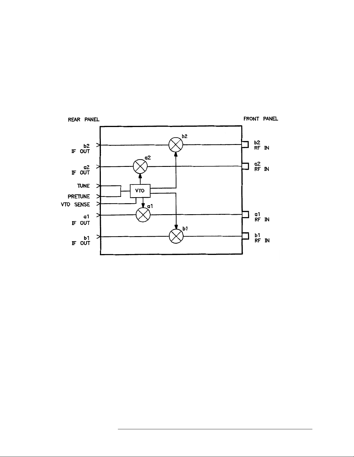
Theory of Operation The RF section of an 8511B frequency converter te st set consists of a
voltage-tun ed osci llator (VT O), a four -wa y po wer spli tte r and fou r samplers .
The frequency converter operates within the frequency range of 45 MHz to
50 GHz. Two reference (a1 and a2), and two test (b1 a nd b2) cha nnels a ccept
RF input by way of the front panel bulkhead connectors.
The VTO/dri ver produces a harmonic that is 20 MHz away from the RF
source frequenc y. The samplers use either the fundamental or a harmonic of
the LO with the reference and test RF signals to develop a 20 MHz IF. The
IF signals are th en routed to the Agilent 85102 by way of the rear panel
connector on the test set.
The LO, generated by the VTO/driver, is phase locked to the source. The
phase lock loop includes the following:
• A3 VTO summing amplifier board
• A14 VTO/driver
• A12 a1 reference sampler assembly
• A13 a2 reference sampl er as sembly and the 8510 network analyzer
A microprocessor on the A4 GPIB board controls the samplers, which may
be switched either on or of f , de pending on the parameter being measured.
The default condition is for all four samplers to be on. This insures that the
test set will be usable in the event of a failure of the A4 GPIB board or a
failure in the communica tion between the test set and the 8510
display/proce ssor.
The 85102 IF detector controls the VTO/dr iver via the VTO summing
amplifie r board. A control voltage is input to the VT O to tune to the corr ect
LO frequency.
Agilent 8511B Test Set Operating and Service Manual 6-1
Page 60
Test Set Troubleshooting
The VTO summing amplifi er board has an output called LENDRA (Low =
END of RAnge) that is sent to the Agilent 85102 IF detector ove r the test set
interconnect cable . This indicates to the Agilent 85101 displa y processor
whether or not the VTO is outside of its nor mal ope rating frequency range.
Should the VTO exceed its normal operating range, the network analyzer
will respond by displ aying the running error message,
message will not be seen in the 8510C. It has been replac ed by
FAILED.
VTO OVER-RANGE. This
PRETUNE
Figure 6-1 Simplified RF Block Diagram
Electrostati c discha rge (ESD) ca n damage or destr oy e lect ronic compone nts.
All work on electronic assemblies should be performed at a static-safe
workstation . Ref er to “Oper ating and Safety Precautions” on page 1-12 for
more information on preventing ESD.
The assemblies handled in this pr ocedur e are very sensitive to damage by
static electr icity. They may or may not contin ue to func tion i f subjec ted to a n
electrostatic dischar ge. In any case, an elect rostatic dischar ge will impair the
reliability of these assemblies. Always perform the steps in order .
6-2 Agilent 8511B Test Set Operating and Service Manual
Page 61

Equipment Needed but Not Supplie d
Table 6-1 Needed Equipment
Test Set Troubleshooting
Equipment Agilent Part Number
1 point Posidriv screwdriver 8710-0899
2 point Posidriv screwdriver 8710-0900
Service adapter 85105-60210
5/16 in torque wrench 8710-1655
Oscilloscope 1740A
Agilent 8511B Test Set Operating and Service Manual 6-3
Page 62

Test Set Troubleshooting
Troubleshooting Sequence
Troubleshooting Sequence
Use this flowcha rt and the following procedu res to det ermine the faulty
assembly.
Figure 6-2 Troubleshooting Flowchart
6-4 Agilent 8511B Test Set Operating and Service Manual
Page 63

A15 Regulator
Test Set Troubleshooting
Troubleshooting Procedures
Troubleshooting Procedures
Procedure 1
Figure 6-3 Power Supply Fuses and Test Points
Agilent 8511B Test Set Operating and Service Manual 6-5
Page 64

Test Set Troubleshooting
Troubleshooting Procedures
A15 Primary
Regulator Board
Use a digital voltmeter to check the voltages and an oscilloscope to check
the ripple in Table 6-2.
Assembly
Table 6-2 Power Supply Voltages
Nominal Voltage Test Point Voltage Range Maximum Ripple
+5.05 Vdc A15TP1 +4.75 to +5.25 2 mV
−5.20 Vdc A15PT2 −4.90 to −5.50 2 mV
+14.85 Vdc A15TP3 +14.10 to +15.60 2 mV
−14.85 Vdc A15TP6 −14.10 to −15.60 2 mV
GPIB Address Switch GPIB Address Switch
Set the switch as indi cated in F igure 6-4 (the dark side of the f ig ure indicate s
where the switch is depressed) . The GPIB address switch is on the
instrument rea r panel. It is ea sy to access but need not be cha nge d unless the
error message
Decimal twenty, binary 00101 (off, off, on, off, on) is the default setting.
SYSTEM BUS ADDRESS ERROR is displayed on the 8510 screen.
Figure 6-4 Instrument GPIB Switch Setti ng
Fuses The locations of the fuses used in the test set are illustrated in Figure 6-3 on
page 6-5. The values of these fuses and their part numbers may be found in
Chapter 8, “Replaceable Parts”.
6-6 Agilent 8511B Test Set Operating and Service Manual
Page 65

Test Set Troubleshooting
Troubleshooting Procedures
Replacement of the Line Module Fuse
1. Pry open line module cover door.
2. Pull out fuse carrier.
3. Insert fuse of proper rating.
4. Place carrier back into line module.
Selection of Operating Voltage
1. Pry open line module cover door.
2. Remove the CAM from the line module.
3. Rotate the cam to the desired voltage. (When the line module cover is
closed, the selected voltage will be visible through a small window.)
4. Insert the cam back into the line module.
5. Close the line module cover door.
Procedure 2
Self-Test Indicators If the ACTIVE LED on the front panel of the instrument fails to light within
five seconds of power on or lights immedi ately, the instrument has not
passed its self-te st. To determine what part of the self-te st has failed, note
which LEDs on the A4 board are lit, see Figure 6-5.
Agilent 8511B Test Set Operating and Service Manual 6-7
Page 66

Test Set Troubleshooting
Troubleshooting Procedures
Figure 6-5 Location of Self-Test Indicators
6-8 Agilent 8511B Test Set Operating and Service Manual
Page 67

Test Set Troubleshooting
Troubleshooting Procedures
Table 6-3 Self-Test Failure Indications
A4 GPIB LEDs
Self-Test Indication
PWON ON ON ON ON 0 to 0.5 seconds
Start ROM Test OFF ON ON ON on briefly
Pass ROM Test OFF OFF ON ON 0.5 to 2.0 seconds
Start RAM Test OFF O FF OFF ON
Pass RAM Test OFF OF F OFF OFF after 2 seconds
LSN TLK SRQ REM
Time (after tur n -o n)
If the Se lf-Test F a ils to Run
If the porti on of memory which contains the self-test progra mming is faulty,
the self-test will not r un properly. The following c onditions indicate that the
GPIB board is most probably faulty.
• all LEDs flash briefly and go off
• all LEDs flash briefly and stay on
• ACTIVE LED goes on too soon
• ACTIVE LED does not go on
Agilent 8511B Test Set Operating and Service Manual 6-9
Page 68

Agilent 85102 IF Amplifier Tes t
Test Set Troubleshooting
Troubleshooting Procedures
Procedure 3
Figure 6-6 Service Adapter Connections
Using the Service Adapter
The service adapter (part number 85102-60210) substitutes for a test set, by
connecting the 20 MHz IF signal from the Agilent 85102 back into the
amplifie r of the Agilent 85102. This is done to determine if a fault is in the
test set or the 85102.
1. Connect the service adapter as shown in Figure 6-6.
2. Press
[RECALL], {MORE}, {FACTORY PRESET}, [MARKER], STIMULUS, [MENU],
[STEP], PARAMETER, [MENU]. Examine each user parameter by pressing
the corresponding softkey to observe the unratioed power level of the
user1 through user4 channe ls. The trace s should be flat lin es, quite cl ose
to each other, as indicated by the marker value (typically about
28 ±5 dB).
−
Service Adapter Conclusions
If all the channels look good. The 85102 is working properly. The problem
is most probably with the source or the test set.
If one or more channels look bad. The problem is most probably with the
85102. Refer to the Agilent 8510 On-Site Service Manual fo r informati on on
troubleshooting the 85102.
6-10 Agilent 8511B Test Set Operating and Service Manual
Page 69

Page 70

Page 71

Table 6-10 Test Sets Interconnect Table (1 of 2)
Mnemonic Description
Active
AB0
AB1
AB2
AB3
AB4
A1S11
A1S10
A1S21
A1S20
A1S31
A1S30
A1S41
A1S40
A1S11
A1S10
Active LED Indicator
Address Bus Bit 0
Address Bus Bit 1
Address Bus Bit 2
Address Bus Bit 3
Address Bus Bit 4
Attenuator 1 Section 1 In
Attenuator 1 Section 1 Out
Attenuator 1 Section 2 In
Attenuator 1 Section 2 Out
Attenuator 1 Section 3 In
Attenuator 1 Section 3 Out
Attenuator 1 Section 4 In
Attenuator 1 Section 4 Out
Attenuator 2 Section 1 In
Attenuator 2 Section 1 Out
Signal Enters
Motherboard
(Connector/Pin)
XA4-3
XA4-29
XA4-8
XA4-30
XA4-9
XA4-31
XA5-4
XA5-26
XA5-24
XA5-3
XA5-23
XA5-2
XA5-25
XA5-1
XA5-44
XA5-22
Signal Enters
(Assembly)
Signal Exits
Motherboard
(Connector)
→
A1 Front
Panel
J1 XA2 XA3 XA4 XA5 J2 J4 J5 J6 J3 XA15 J8 J9 J7
A2 IF
Multiplexer
A3 VTO
Summing
Amp
A4 GPIB
A5
Attenuator/
Switch
A10
Sampler
A11
Sampler
A12
Sampler
A13
Sampler
A14 VTO/
Driver
A15
Regulator
A16 Step
Attenuator 1
A17 Step
Attenuator 2
→
4
29
8
30
9
31
29
8
30
29
8
30
2
13
9
3
5
11
10
4
2
13
A20 Rear
Panel
A2S21
A2S20
A2S31
A2S30
A2S41
A2S40
BNMINT
BSRQ
DB0
DB1
DB2
DB3
DB4
DB5
DB6
DB7
GND
LAP1
LAP2
LATDRVP
Attenuator 2 Section 2 In
Attenuator 2 Section 2 Out
Attenuator 2 Section 3 In
Attenuator 2 Section 3 Out
Attenuator 2 Section 4 In
Attenuator 2 Section 4 Out
Buffered Non-Maskable Interrupt
Buffered Service Request
Data Bus Bit 0
Data Bus Bit 1
Data Bus Bit 2
Data Bus Bit 3
Data Bus Bit 4
Data Bus Bit 5
Data Bus Bit 6
Data Bus Bit 7
Chassis Ground
Low = Port 1 Attenuator Present
Low = Port 2 Attenuator Present
Low = Attenuator Switch/Driver
Present
XA5-18
XA5-42
XA5-40
XA5-20
XA5-19
XA5-41
XA4-28
XA4-2
XA4-15
XA4-37
XA4-16
XA4-38
XA4-17
XA4-39
XA4-18
XA4-40
XA15-18-23, 40-44
J8-1
J9-1
XA5-43
4
28
Motherboard Pin Numbers
39
3, 5 11, 12, 33, 34 11, 12, 33, 34
28
15
37
16
38
17
39
18
40
15
37
16
38
17
18
40
19
41
44
9
3
5
11
10
4
28
2
15
37
16
38
11, 12, 33, 34 11, 12, 33, 342122223, 4 1414
Page 72

Table 6-11 Test Sets Interconnect Table (2 of 2)
Mnemonic Description
LBIOS
LBUFWR
LENDRA
LOPTP
LPRTHLD
LP2ACT
LSWDRVP
LTEMP
PWON
P1ACT
P1BIASIN
P1BIASOUT
P2BIASIN
P2BIASOUT
SWEPTBIAS
SBA1
Low = Buffered !/O Strobe
Low = buffered Write
Low = End of Range
Low = Option Present
Low = Preturn Hold
Low = Port 2 Active
Low = Sweep Driver Present
Low = Over Temperature
Power On
Port 1 Active
Port 1 Bias Voltage In
Port 1 Bias Voltage Out
Port 2 Bias Voltage In
Port 2 Bias Voltage Out
Swept Bias
A1 Sampler On/Off
Signal Ente r s
Motherboard
(Connector/Pin)
XA4-5
XA4-27
XA3-43
XA2-20
J11-17
XA4-4
XA3-21
XA3-7
XA4-6
XA4-26
J8 (Rear Panel)
Port 1 (Front Panel)
J6 (Rear Panel)
Port 2 (Front Panel)
XA3-24
XA3-4
Signal Enters
(Assembly)
Signal Exits
Motherboard
(Connector)
A1 Front
Panel
→
J1 XA2 XA3 XA4 XA5 J2 J4 J5 J6 J3 XA15 J8 J9 J7
A2 IF
Multiplexer
A3 VTO
Summing
Amp
A4 GPIB
A5
Attenuator/
Switch
A10
Sampler
A11
Sampler
A12
Sampler
A13
Sampler
A14 VTO/
Driver
A15
Regulator
A16 Step
Attenuator 1
→
5
20
6
77
66 6 1
19, 20
17, 18
15, 16
13, 14
5
27
5
43
7
1151
A17 Step
Attenuator 2
A20 Rear
Panel
2
3
SBA2
SBB1
SBB2
TEMP2
VSET
+5VA
+5VCAP
-5VCAP
+15VCAP
-15VCAP
+5VREG
-5VREG
+15VREG
-15VREG
A2 Sampler On/Off
B1 Sampler On/Off
B2 Sampler On/Off
Analog Temperature Sensor
VTO Set Volt age
+5 Volts to Attenuators
+5 Volts Unregulated to Input Filter Capacitor
−5 Volts Unregulated to Input Filter Capacitor
+15 Volts Unregulated to Input Filter Capacitor
−15 Volts Unregulated to Input Filter Capacitor
+ 5 Volts Regulated Supply
−15 Volts Regulated Supply
+15 Volts Regulated Supply
−15 Volts Regulated Supply
XA3-26
XA3-3
XA3-25
XA3-1
XA3-2
XA15-17, 39
XA15-45
XA15-8, 9, 30, 31
XA15-12, 13, 34, 35
XA15-16, 17, 38, 39
XA15-2, 3, 24, 25
XA15-6, 7, 28, 29
XA15-10, 11, 32, 33
XA15-14, 15, 36, 37
Motherboard Pin Numbers
5
1
13, 14
1, 2 14, 36 14, 36 14, 36 9, 10
7, 8
7, 8 10, 32
13, 35
10, 32
13, 35
10, 32
13, 35
10, 32
13, 35
4
3
4
3
4
3
4
3
11, 12
5, 6
66
26, 27
8, 9, 30, 31
12, 13, 34
16, 17, 38, 39
Page 73

Replacement Procedures
7 Replacement Procedures
Introduction This chapter consists of the following replacement procedures:
(1) Frequen cy converter
(2) Regulator bo ard as s embl y
(3) Filter capacitors
(4) 2.4 mm RF connectors
(5) B1 fan
(6) T1 power transformer
Equipment Needed But Not Supplied
Table 7-1 lists all the equipment needed to replace the assemblies
documented in the follo wing procedures. Use Figure 7-1 on page 7-2 to
locate the assemblies in the Agilent 8511B test set.
Table 7-1 Equipment Needed to Replace Test Set Major Assemblies
Tools Used For Agilent Part Number
2 point pozidriv screwdriver all components 8710-0900
1 point pozidriv screwdriver all components 8710-0899
5/16-inch torque wrench, 90 N-cm (8 in-lb) all components 8710-1765
2.4 mm gauge kit port connectors 85056A calibration kit
Anti-static mat all components 9300-0797
Wrist strap all components 9300-0910
Clip lead C1 - C4 capacitors any supplier
Wire cutters B1 fan any supplier
T-10 TORX screwdriver all components 8710-1623
T-15 Torts screwdriver all components 8710-1622
9/16-inch nut driver connector repair 8720-0008
1/2-inch torque wrench, 280 N-cm (25 in-lb) connector repair 8710-1581
100 ohm 20 watt resistor C1 - C4 capacitor removal 0819-0019
5/16 open-end wrench fan replacement any supplier
1/2-inch open-end wrench RF input connector any supplier
Agilent 8511B Test Set Operating and Service Manual 7-1
Page 74

Replacement Procedures
Figure 7-1 Assembly Location Diagram
7-2 Agilent 8511B Test Set Operating and Service Manual
Page 75

Replacement Procedures
Preliminary Precautions
CAUTION ESD can damage or destroy electronic components. They may or may not
continue to function if subje cted to an electrostatic discharge. Their
reliability will, however, be impair ed. All work on electronic assemblies
should be performed at a static- sa fe workstation. Refer to “Operating and
Safety Precautions” on page 1-12 for more information.
1. To prevent electrostat ic damage, ground the work area and yourself.
2. Turn the 8511B test set off.
3. Disconnect the power cord.
4. Remove the top and side covers, trim strips and the handles.
5. Torque the 2.4 mm connections to 90 N-cm (8 in-lb).
6. Exercise caution when handling semi-rigid coax cabl es. The y are easily
bent.
7. To install a part, reverse the appropriate procedure.
Agilent 8511B Test Set Operating and Service Manual 7-3
Page 76

Replacement Procedures
NOTE To install a new pa rt in the following procedures, reverse the steps.
(1) Replacing the Frequency Converter
WARNING Turn the test set OFF and disconnect the powe r cord form the mains.
Electrocution can result if power is not removed from the test set prior to this
procedure
The frequency converter consists of a voltage-tu ned oscillator (VTO)
assembly and four samplers.
1. Remove the semi-rigid cable attached to each of the four samplers.
2. Remove the two in-line attenuators from the sample rs .
(2) Replacing the Regulator Board Assembly
3. Remove the six flexible cables from the frequency converter by gently
pulling on the gold connector.
4. Remove the four frequency converter mounting plate screws and the
bracket screw that fastens the frequency converter to the chassis.
5. Unplug the ribbon cable near the front panel.
6. Unplug the four harnessed (multi-colored) wire and socket assemblies.
7. Lift the frequency converter out of the test set.
8. Remove the frequency converter bracket by removing the two pozidriv
screws.
1. Unplug the transformer socket from the regulator board.
2. Remove the three mounting screws from the top edge of the re gula tor
board.
3. Remove the regulator board. (You may have to partial ly back out one of
the transformer mounting sc rews for clearance.)
(3) Replacing the Filter Capacitors
1. Set the test set upright and pull the metal and plastic cover off the
capacitors.
2. Turn the test set over and remove the bottom cover.
3. T o di schar ge the cap acitors atta ch one en d of an insu la ted clip l ead t o the
chassis of the instrument a nd the other end of the clip lead to a 100
watt resistor. Use the resistor to discharge each capacit or terminal (large
pozidri v scre w on the botto m side of t he tes t set). Ea ch capac itor ha s two
7-4 Agilent 8511B Test Set Operating and Service Manual
Ω 20
Page 77

Replacement Procedures
terminals. Discharge all capacitor terminals. It takes approximately six
seconds to discharge each capacitor.
4. T o r emove a capa citor, remov e the cor resp onding pair of screws and pull
the capacitor out of the test se t.
Agilent 8511B Test Set Operating and Service Manual 7-5
Page 78

Replacement Procedures
(4) Repairing a
2.4 mm RF Connector
Figure 7-2 Exploded Diagram of a 2.4 mm Connector
Refer to Figure 7-2 and the following text to repair a 2.4 mm connector.
Refer to the “Repla cea b le Parts” sect ion of this manual for replacement part
numbers.
Disassembly
1. Remove any attached cables from the connector to be replac ed.
2. From inside the test set, use a 9/16-inch nut driver to loosen the nut and
remove the connec tor.
Assembly
3. Assemble the bulkhead connector, lock washer and nut.
4. Using the 9/16-inch nut-driver, tighten the nut to 506 N-cm (45 in-lb).
5. Attach the assembly to the bulkhead connector. Torque to 281 N-cm
(25 in-lb).
6. Clean the mating surfaces with alcohol and lint-free swabs.
7. Check the pin depth of the gold nose connector. The pin depth
specification is 0.0000 to +0.0030 inch.
8. Reconnect the cables disconnected in step 1.
7-6 Agilent 8511B Test Set Operating and Service Manual
Page 79

Replacement Procedures
(5) Replacing the B1 Fan
WARNING Turn the test set OFF and disconnect the po wer cord from the mains.
Electrocution can result if power is not removed from the test set prior to this
procedure.
To replace the fan (B1), you must remove the transformer (T1) so that the
ends of the fan wires can be unsoldered from the line module FL1. See
Figure 8-5 on page 8-7 for a detailed view of the fan and trans fo rm er
hardware.
1. Turn the test set on its right side.
2. Unplug the transformer connector at J2 on the A15 regulator board.
3. U s ing a large pozidriv screwdriver, remove the four screws and washers
that hold the transfor mer onto the rear panel.
4. Using a large pozidriv screwdriver, remov e the screw that holds the
transformer angle brac ket to the main deck. The transformer wires
soldered to the line module are short, so do not pull the transformer out
too far.
5. Carefully remove the transformer from the test set and put it on the
bench close to the test set.
6. Strip the heat shrink tubing off of the two fan wires and unsolde r the
wires from the line module. Cut any cabl e ties holding the fan wires to
nearby cables.
7. Using a small pozidriv screwdriver, remove the screw and lockwasher
that secure the green/ye llow fan ground wire to the top of the rear panel
frame.
8. Using a small pozidriv screwdrive r, remove the four scre ws that hold t he
fan to the rear panel and remove the fan.
Agilent 8511B Test Set Operating and Service Manual 7-7
Page 80

Replacement Procedures
(6) T1 Power Tr ansformer
WARNING Turn the test set OFF and disconnect the powe r cord from the mains.
Electrocution can result if power is not removed from the test set prior to this
procedure.
1. Turn the test set on its right side.
2. Unplug the transformer connector at J2 on the A15 regulator board.
3. Using a large pozidriv screwdriver, remove the four screws and washers
that hold the transfor mer onto the rear panel.
4. Using a large pozidriv screwdriver, remov e the screw that holds the
transformer angle brac ket to the main deck. The transformer wires
soldered to the line module are short, so do not pull the transformer out
too far.
5. Carefully remove the transformer from the test set and put it on the
bench close to the test set.
6. Strip the heat shrink tubing of f the transformer wire s soldered to the line
module, and unsolder the wires.
7. Unsolder the transformer ground wire connected to the chassis sid e rai l.
8. Remove the transformer.
When you replace the transf or mer, refer to Figure 7-3 for the location of the
wires connected to the line module .
Figure 7-3 Wire Connections to the Line Module FL1
7-8 Agilent 8511B Test Set Operating and Service Manual
Page 81

Replaceable Parts
8 Replaceable Parts
Introduction This chapter contains information f or orde ring part s. The “Replaceable Parts
List” section describes how to order assemblies which are available on an
exchange basis.
Replaceable Parts List Each part is liste d both in the fi gur es and the table s by reference designators.
Quantity refers to the tota l number of the part in the instrument. The
description is a brief written description of the part and may be used for
ordering purposes.
Reference Designations
• A = assembly
• B = fan
• C = capacitor
• W = cable, wire
• T = transformer
Ordering Information To order a listed part, quot e the Agile nt part number, quantity required, and
send the order to the nearest Agilent office.
To order a part that is not listed, include the instrument model number,
complete serial number, descripti on and func tion of the part, and quantity
required. Send the order to the neare st Agilent off ice.
Agilent 8511B Test Set Operating and Service Manual 8-1
Page 82

Replaceable Parts
Exchange Assemblie s Available
The assemblies below are replaceable on a rebuilt exchange basis at a cost
saving. They are not fie ld-repairable. Defective assemblies must be returned
for credit to realize the cost savings. Thus, assemblies required for spare
parts stock should be ordered by the new assembly part number which is
included in the replaceable parts list of this section. See the parts list
for the orderable part numbers, and Figur e 8-1 on page 8-3 for the
Rebuilt-Exchange flow-chart.
• A2 = IF multiplexer board ass embly (option 001 only)
• A3 = VTO summing amplifier boa rd assembly
• A4 = GPIB board assembly
• A10, A11, A12, A13 plus A14 = sampler assembly
(inputs bl, b2, a1, a2 and A14 VTO driver)
• A15 = regulator board asse mbly
8-2 Agilent 8511B Test Set Operating and Service Manual
Page 83

Replaceable Parts
Figure 8-1 Low Cost Rebuilt-Exchange Procedure
Agilent 8511B Test Set Operating and Service Manual 8-3
Page 84

Replaceable Parts
Figure 8-2 Major Assemblies
8-4 Agilent 8511B Test Set Operating and Service Manual
Page 85

Replaceable Parts
Figure 8-3 Semi-Rigid Cables
Agilent 8511B Test Set Operating and Service Manual 8-5
Page 86

Replaceable Parts
Figure 8-4 Flexible RF Cables
8-6 Agilent 8511B Test Set Operating and Service Manual
Page 87

Replaceable Parts
Figure 8-5 Detailed Views of Rear Pan el Miscellaneous Parts
Agilent 8511B Test Set Operating and Service Manual 8-7
Page 88

Replaceable Parts
Figure 8-6 Miscellaneous Motherboard Parts
8-8 Agilent 8511B Test Set Operating and Service Manual
Page 89

Replaceable Parts Lists
Table 8-1 Agilent 8511B Replaceable Parts
Reference Designation Agilent Part Number Qty Description
Major Assemblies:
A1 08511-60011 1 Assembly, front panel
A3 08517-60002 1 VTO summing amplifier board assembly
A3 08517-69002 1 VTO summing amplifier board assembly (rebuilt)
A4 1 GPIB board assembly
A4 1 GPIB board assembly (rebuilt)
A10, A11, A12, A13, A14 5086-7501 1 Sampler assembly + VTO driver
A10, A11, A12, A13, A14 5086-6501 1 Sampler assembly + VTO driver (rebuilt)
Replaceable Parts
A15 08513-60007 1 Regulator board assembly
A19 08513-60001 1 Motherboard assembly
A20 1 GPIB interface board assembly
A20 1 GPIB interface board assembly (rebuilt)
T1 9100-4616 1 Transformer power
Cable Assemblies:
W13 08513-60133 1 Cable assembly A3J1 to A14J1
W14 08513-60134 1 Cable assembly A3J2 to J11A7
W16 08513-60136 1 Cable assembly A3J5 to J11A5
W18 08513-60138 1 Cable assembly A3J7 to J11A6
W20 08513-60140 1 Cable assembly A3J4 to J14J2
W24 08513-60144 1 Cable assembly A12J3 to J11A1
W25 08513-60145 1 Cable assembly A13J3 to J11A4
W26 08513-60146 1 Cable assembly A10J3 to J11A2
W27 08513-60147 1 Cable assembly A11J3 to J11A3
W29 1 Cable assembly line switch
W30 1 Cable assembly J10 to J11
W31 08511-20021 1 Cable assembly A10 to front panel
W32 08511-20024 1 Cable assembly A11 to front panel
W33 08511-20022 1 Cable assembly A12 to front panel
W34 08511-20023 1 Cable assembly A13 to front panel
Agilent 8511B Test Set Operating and Service Manual 8-9
Page 90

Replaceable Parts
Table 8-1 Agilent 8511B Replaceable Parts ( Contin ued)
Reference Designation Agilent Part Number Qty Description
W42 1 Cable assembly A4 to A20
W43 1 Cable assembly A1 to A19
08510-60102 1 Test set cable assembly
08511-60021 1 Cable SMA/SMB 150C
08511-60022 1 Cable SMA/SMB 150C
8120-1348 1 Cable 03 C 03 F 03 M (power cord)
8120-3445 1 Cable 24 C 24 F 24 F (GPIB)
Fuses:
2110-0043 2 1.5 A fuse (rear panel and regulator board)
2110-0001 1 1 A fuse (regulator board)
2110-0002 1 1.5 A fuse (regulator board)
Miscellaneous Parts:
C1, C2, C3, C4 0180-2671 4 Capacitor 0.012F 30 Vdc AL (motherboard)
U19 08517-80005 1 EPROM
08511-90073 1 Agilent 8511B Operating and Service Manual
08510-90360 1 Quick Reference Connector Care Card
08511-60024 1 Agilent 8511A/B and Antenna Measurement System Performance Verification
Software Assembly
08512-20005 1 RFI gasket
08513-00001 1 Deck
08513-00005 1 Mounting bracket LH
08513-00006 1 Mounting bracket RH
08513-00015 1 Plate, support cap
08513-00017 1 Bracket CONV assembly
08513-00018 1 Insulator brace
08513-00037 1 Bracket enclosure
08513-00040 1 Cover (test set top)
08513-00041 1 Cover (side PERF)
08513-20013 1 Brace (deck)
08513-20015 1 Mounting bar
08513-60156 1 ENC assembly doubler
08513-65002 1 INTMD board assembly
08517-60005 1 Rear panel assembly
8-10 Agilent 8511B Test Set Operating and Service Manual
Page 91

Table 8-1 Agilent 8511B Replaceable Parts ( Contin ued)
Reference Designation Agilent Part Number Qty Description
0955-0207 1 Attenuator 5 dB 2 W SMA
1250-1251 1 Adapter F SMA to F SMA
1252-4694 1 CAP PROT 50 pin F
1252-4695 1 CAP PROT 50 pin M
1252-5007 1 CAP PROT 24 pin F
1400-0054 1 CLP CA .07 D .37 W
1400-0650 2 CLP CA .25 D .75 W
1400-0757 1 CLP CA .25 D 1.0 W
1400-1209 1 CLP CA .69 D 1.0 W
1401-0050 3 CAP PROT .125 ID
1401-0245 5 CAO CIBD .240 ID
Replaceable Parts
5021-5804 1 Frame FM rear
5021-5837 4 Corner strut
5021-8403 1 FR front 132.6 H
5040-6988 1 Front frame cover
5041-8801 4 Foot FM .5 M
5041-8821 2 Rear panel standoff
5062-3747 1 Cover (bottom)
5062-3757 1 Cover (side)5062-3989
5062-3989 1 Front handle kit
5062-7243 4 Connector assembly (bulkhead)
5962-0476 1 Certificate of Calibration
85120-00041 2 Cover (blank)
Agilent 8511B Test Set Operating and Service Manual 8-11
Page 92

Replaceable Parts
Figure 8-7 Parts Unique to Option 001
8-12 Agilent 8511B Test Set Operating and Service Manual
Page 93

Table 8-2 Replaceable Parts for Agilent 8511B Option 001
Reference Designation Agilent Part Number Qty Description
08510-60106 1 Cable assembly IF test
08510-60102 1 Test set cable assembly
A2 08513-60004 1 IF multiplexer board assembly (new)
A2 08513-69004 1 IF multiplexer board assembly (rebuilt)
W1 08513-60121 1 Cable assembly A12J3 to A2J1
W2 08513-60122 1 Cable assembly A13J3 to A2J7
W3 08513-60123 1 Cable assembly A10J3 to A2J4
W4 08513-60124 1 Cable assembly A11J3 to A2J10
W5 08513-60125 1 Cable SMB/MSC 635W
W6 08513-60126 1 Cable SMB/MSC 533W
W7 08513-60127 1 Cable SMB.MSC 737W
Replaceable Parts
W8 08513-60128 1 Cable assembly A2J11-J11A3
W9 08513-60129 1 Cable SMB/MSC 711W
W10 08513-60130 1 Cable SMB/MSC 456W
W11 08513-60131 1 Cable SMB/MSC 762W
W12 08513-60132 1 Cable SMB/MSC 457W
W15 08513-60135 1 Cable SMB/MSC 610W
W17 08513-60137 1 Cable SMB/MSC 4836W
W19 08513-60139 1 Cable SMB/MSC 457W
Agilent 8511B Test Set Operating and Service Manual 8-13
 Loading...